Fortinet Version 3 0 Users Manual FortiBridge Administration Guide
Version 3.0 to the manual a15670b6-54e8-4c0a-9d8e-810d1b8ccfcf
2015-02-09
: Fortinet Fortinet-Version-3-0-Users-Manual-551695 fortinet-version-3-0-users-manual-551695 fortinet pdf
Open the PDF directly: View PDF ![]() .
.
Page Count: 88
- Contents
- Introduction
- FortiBridge operating principles
- Setting up FortiBridge units
- Configuration and operating procedures
- Using the CLI
- config CLI commands
- execute CLI commands
- Index

www.fortinet.com
FortiBridge
Version 3.0
Administration Guide

FortiBridge Administration Guide
Version 3.0
9 November 2006
09-30000-0163-20061109
© Copyright 2006 Fortinet, Inc. All rights reserved. No part of this publication including text, examples,
diagrams or illustrations may be reproduced, transmitted, or translated in any form or by any means,
electronic, mechanical, manual, optical or otherwise, for any purpose, without prior written permission of
Fortinet, Inc.
Trademarks
ABACAS, APSecure, FortiASIC, FortiBIOS, FortiBridge, FortiClient, FortiGate, FortiGuard, FortiGuard-
Antispam, FortiGuard-Antivirus, FortiGuard-Intrusion, FortiGuard-Web, FortiLog, FortiManager, Fortinet,
FortiOS, FortiPartner, FortiProtect, FortiReporter, FortiResponse, FortiShield, FortiVoIP, and FortiWiFi are
trademarks of Fortinet, Inc. in the United States and/or other countries. The names of actual companies
and products mentioned herein may be the trademarks of their respective owners.
Regulatory compliance
FCC Class A Part 15 CSA/CUS
!Caution: If you install a battery that is not the correct type, it could
explode. Dispose of used batteries according to local regulations.

Contents
FortiBridge Version 3.0 Administration Guide
09-30000-0163-20061109 3
Contents
Introduction ........................................................................................ 7
About FortiBridge.............................................................................................. 7
About this document......................................................................................... 7
Fortinet documentation..................................................................................... 8
Fortinet tools and documentation CD............................................................ 8
Fortinet Knowledge Center ........................................................................... 8
Comments on Fortinet technical documentation........................................... 8
Customer service and technical support ........................................................ 8
FortiBridge operating principles ...................................................... 9
Example FortiBridge application...................................................................... 9
Connecting the FortiBridge unit................................................................... 10
Normal mode operation .................................................................................. 11
How the FortiBridge unit monitors the FortiGate unit .................................. 11
Probes and FortiGate firewall policies......................................................... 12
Enabling probes to detect FortiGate hardware failure................................. 13
Enabling probes to detect FortiGate software failure .................................. 13
Probe interval and probe threshold ............................................................. 13
Bypass mode operation.................................................................................. 14
FortiBridge power failure................................................................................ 14
Example FortiGate HA cluster FortiBridge application................................ 15
Connecting the FortiBridge-1000 (copper gigabit ethernet) ........................ 15
Connecting the FortiBridge-1000F (fiber gigabit ethernet).......................... 16
Example configuration with other FortiGate interfaces............................... 16
Setting up FortiBridge units............................................................ 19
FortiBridge unit basic information................................................................. 19
FortiBridge-1000 Package contents............................................................ 19
FortiBridge-1000F Package contents.......................................................... 20
Mounting instructions .................................................................................. 20
Technical specifications .............................................................................. 21
LED indicators............................................................................................. 21
Connectors.................................................................................................. 22
Factory default configuration....................................................................... 22
Connecting and turning on the FortiBridge unit .......................................... 23
Connecting and turning on the FortiBridge-1000 unit ................................. 23
Connecting and turning on the FortiBridge-1000F unit ............................... 24
Connecting to the command line interface (CLI).......................................... 25
Connecting to the FortiBridge console ........................................................ 25
Connecting to the FortiBridge CLI using Telnet .......................................... 26

FortiBridge Version 3.0 Administration Guide
409-30000-0163-20061109
Contents
Completing the basic FortiBridge configuration.......................................... 26
Adding an administrator password.............................................................. 27
Changing the management IP address ...................................................... 27
Changing DNS server IP addresses ........................................................... 28
Adding static routes .................................................................................... 28
Allowing management access to the EXT 1 interface................................. 29
Changing the system time and date ........................................................... 29
Adding administrator accounts.................................................................... 29
Resetting to the factory default configuration.............................................. 30
Installing FortiBridge unit firmware............................................................... 30
Upgrading to a new firmware version ......................................................... 31
Reverting to a previous firmware version.................................................... 32
Installing firmware from a system reboot .................................................... 33
Configuration and operating procedures...................................... 35
Example network settings .............................................................................. 35
Configuring FortiBridge probes..................................................................... 36
Probe settings ............................................................................................. 37
Enabling probes .......................................................................................... 38
Verifying that probes are functioning .......................................................... 39
Tuning the failure threshold and probe interval........................................... 40
Configuring FortiBridge alerts ....................................................................... 40
FortiBridge alert email................................................................................. 41
FortiBridge syslog ....................................................................................... 41
FortiBridge SNMP ....................................................................................... 42
Recovering from a FortiGate failure .............................................................. 43
Manually switching between FortiBridge operating modes........................ 44
Backing up and restoring the FortiBridge configuration ............................ 44
Using the CLI.................................................................................... 47
CLI basics......................................................................................................... 47
Connecting to the FortiBridge CLI using SSH or Telnet.............................. 47
Setting administrative access for SSH or Telnet......................................... 47
Connecting to the FortiBridge CLI using SSH............................................. 48
config CLI commands ..................................................................... 51
alertemail setting............................................................................................. 52
log syslogd setting.......................................................................................... 54
probe probe_list {ping | http | ftp | pop3 | smtp | imap}............................... 55
probe setting.................................................................................................... 56
system accprofile ............................................................................................ 57
system admin................................................................................................... 59

Contents
FortiBridge Version 3.0 Administration Guide
09-30000-0163-20061109 5
system console................................................................................................ 61
system dns....................................................................................................... 62
get system status ............................................................................................ 63
system fail_close............................................................................................. 64
system global................................................................................................... 66
system interface {internal | external}............................................................. 68
system manageip............................................................................................. 69
system route .................................................................................................... 70
system snmp community................................................................................ 71
config hosts ................................................................................................. 71
execute CLI commands................................................................... 73
backup .............................................................................................................. 74
date ................................................................................................................... 75
factoryreset ...................................................................................................... 76
ping ................................................................................................................... 77
reboot................................................................................................................ 78
restore............................................................................................................... 79
switch-mode..................................................................................................... 80
time ................................................................................................................... 81
Index.................................................................................................. 83

FortiBridge Version 3.0 Administration Guide
609-30000-0163-20061109
Contents
Introduction About FortiBridge
FortiBridge Version 3.0 Administration Guide
09-30000-0163-20061109 7
Introduction
This chapter introduces you to the FortiBridge-1000 and FortiBridge-1000F
products that provide fail open protection for FortiGate Antivirus Firewalls
operating in transparent mode. Fail open protection keeps network traffic flowing
in the event of a FortiGate unit failure. This chapter contains the following topics:
•About FortiBridge
•About this document
•Fortinet documentation
•Customer service and technical support
About FortiBridge
The FortiBridge products are a solution for enterprise organizations to provide fail
open protection for FortiGate units deployed inline in transparent mode. The
FortiBridge products use multiple probe protocols to detect failures in the
FortiGate unit. FortiBridge zero power fail open technology means that the
FortiBridge unit also fails open if a power failure occurs.
Figure 1: FortiBridge unit
A FortiBridge unit functions as a pass-through device when a FortiGate unit or
FortiGate HA cluster operating in transparent mode fails or loses power. The
FortiBridge unit bypasses the FortiGate unit to make sure that the network can
continue processing traffic. The FortiBridge unit is not a firewall or antivirus
device. FortiGate services are not applied when the FortiBridge unit bypasses
traffic.
About this document
This document describes how to install, configure and maintain the
FortiBridge-1000 and the FortiBridge-1000F products.
This document contains the following chapters:
•FortiBridge operating principles contains general information about how
FortiBridge units work.
•Setting up FortiBridge units contains hardware reference and general
installation procedures for FortiBridge units.
•Configuration and operating procedures contains procedures for connecting
and configuring FortiBridge units.
PWR
INT 1
INT 2 NORMAL
EXT 2
EXT 1 BYPASS MODE MODE FACTORY RESET
FortiGate
Esc Enter

FortiBridge Version 3.0 Administration Guide
809-30000-0163-20061109
Fortinet documentation Introduction
•Using the CLI describes how to use the FortiBridge CLI.
•config CLI commands is the FortiBridge config CLI command reference.
•execute CLI commands is the FortiBridge execute CLI command reference.
Fortinet documentation
The most up-to-date publications and previous releases of Fortinet product
documentation are available from the Fortinet Technical Documentation web site
at http://docs.forticare.com.
The following FortiBridge product documentation is available:
• FortiBridge QuickStart Guides
Provide basic information about connecting and installing a FortiBridge unit.
• FortiBridge Administration Guide
Describes how to install, configure, and manage a FortiBridge unit.
Fortinet tools and documentation CD
All Fortinet documentation is available from the Fortinet Tools and Documentation
CD shipped with your Fortinet product. The documents on this CD are current for
your product at shipping time. For the latest versions of all Fortinet documentation
see the Fortinet Technical Documentation web site at http://docs.forticare.com.
Fortinet Knowledge Center
Additional Fortinet technical documentation is available from the Fortinet
Knowledge Center. The knowledge center contains troubleshooting and how-to
articles, FAQs, technical notes, and more. Visit the Fortinet Knowledge Center at
http://kc.forticare.com.
Comments on Fortinet technical documentation
Please send information about any errors or omissions in this document, or any
Fortinet technical documentation, to techdoc@fortinet.com.
Customer service and technical support
Fortinet Technical Support provides services designed to make sure that your
Fortinet systems install quickly, configure easily, and operate reliably in your
network.
Please visit the Fortinet Technical Support web site at http://support.fortinet.com
to learn about the technical support services that Fortinet provides.

FortiBridge operating principles Example FortiBridge application
FortiBridge Version 3.0 Administration Guide
09-30000-0163-20061109 9
FortiBridge operating principles
This chapter describes a typical transparent mode FortiGate network and how to
add a FortiBridge unit to this network to provide fail open protection. This chapter
also contains detailed information about how FortiBridge units operate and
concludes with descriptions of adding a FortiBridge unit to an HA cluster and
connecting a FortiBridge unit other FortiGate interfaces.
This chapter contains the following sections:
•Example FortiBridge application
•Normal mode operation
•Bypass mode operation
•FortiBridge power failure
•Example FortiGate HA cluster FortiBridge application
•Example configuration with other FortiGate interfaces
Example FortiBridge application
A typical application of a FortiGate unit operating in transparent mode is to insert
the FortiGate unit into an internal network, between the network and the router
that connects the network to the Internet. In this configuration, the FortiGate unit
can provide security services for all traffic passing between the internal network
and the internet. These security services can include:
• applying firewall policies and IPS attack prevention to all traffic,
• applying virus scanning to HTTP, FTP, POP3, SMTP, and IMAP traffic,
• applying web filtering to HTTP traffic,
• applying Spam filtering to POP3, SMTP, and IMAP traffic.
The internal network is connected to the FortiGate unit internal interface. The
router is connected to the FortiGate unit external interface. The FortiGate unit can
be added to the network without changing the configuration of the network (except
to add the FortiGate management IP address).
Figure 2: Example transparent mode network
To allow users on the internal network to connect to resources on the Internet, add
Internal -> External firewall policies to the FortiGate unit. Add protection profiles
to the firewall policies to apply security services such as virus scanning, web
filtering, spam filtering and IPS to the traffic that passes through the FortiGate unit.
Router
Internal External
(Transparent mode)
Internal network
Internet
FortiBridge Version 3.0 Administration Guide
10 09-30000-0163-20061109
Example FortiBridge application FortiBridge operating principles
The FortiGate unit acts as an extra layer of protection for your internal network.
While it is operating, the FortiGate unit protects the internal network from threats
originating on the Internet. All users on the internal network connect through the
FortiGate unit to the Internet. This also means that if a failure or other interruption
caused the FortiGate unit to stop functioning, users on the internal network would
not be able to connect to the Internet.
You can install a FortiBridge unit to maintain internet connectivity for the internal
network if the FortiGate unit stops functioning. The FortiBridge unit provides fail
open protection for your network by bypassing the FortiGate unit if a failure
occurs.
Connecting the FortiBridge unit
Operating in normal mode, the FortiBridge unit functions like a layer-2 bridge,
passing all traffic to the FortiGate unit. The FortiGate unit processes the traffic,
which then passes through the FortiBridge unit again and then to its final
destination.
In most cases, you do not have to make changes to the FortiGate unit
configuration or to the network to add a FortiBridge unit. The only network
requirement for FortiBridge is the availability of a single management IP address
for the FortiBridge unit. The FortiBridge management IP address is required in
addition to the FortiGate management IP address.
The connection procedure is different depending on whether the FortiBridge unit
uses copper gigabit ethernet network connections or fiber gigabit ethernet network
connections. This section includes the following connection procedures:
•Connecting the FortiBridge-1000 (copper gigabit ethernet)
•Connecting the FortiBridge-1000F (fiber gigabit ethernet)
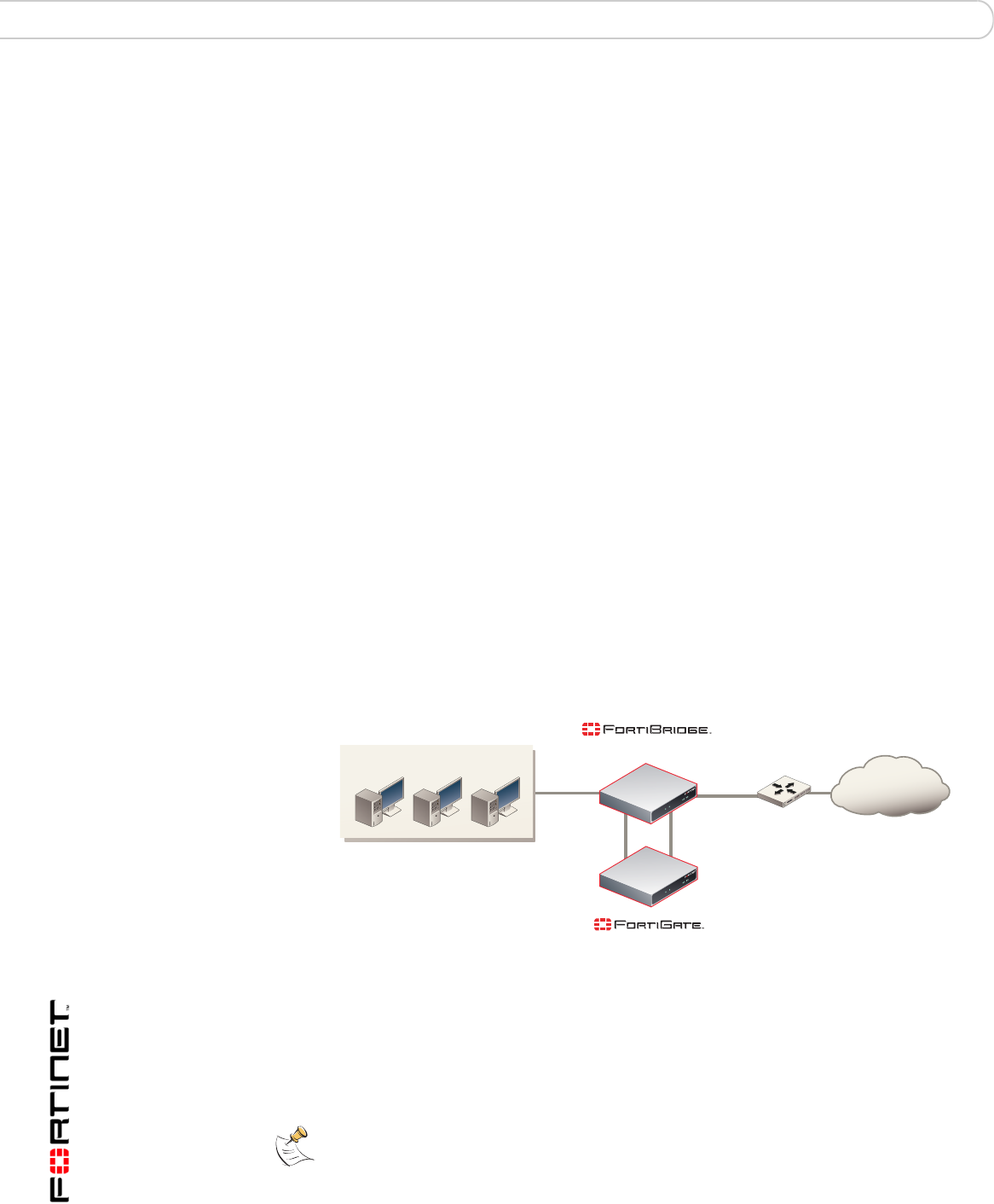
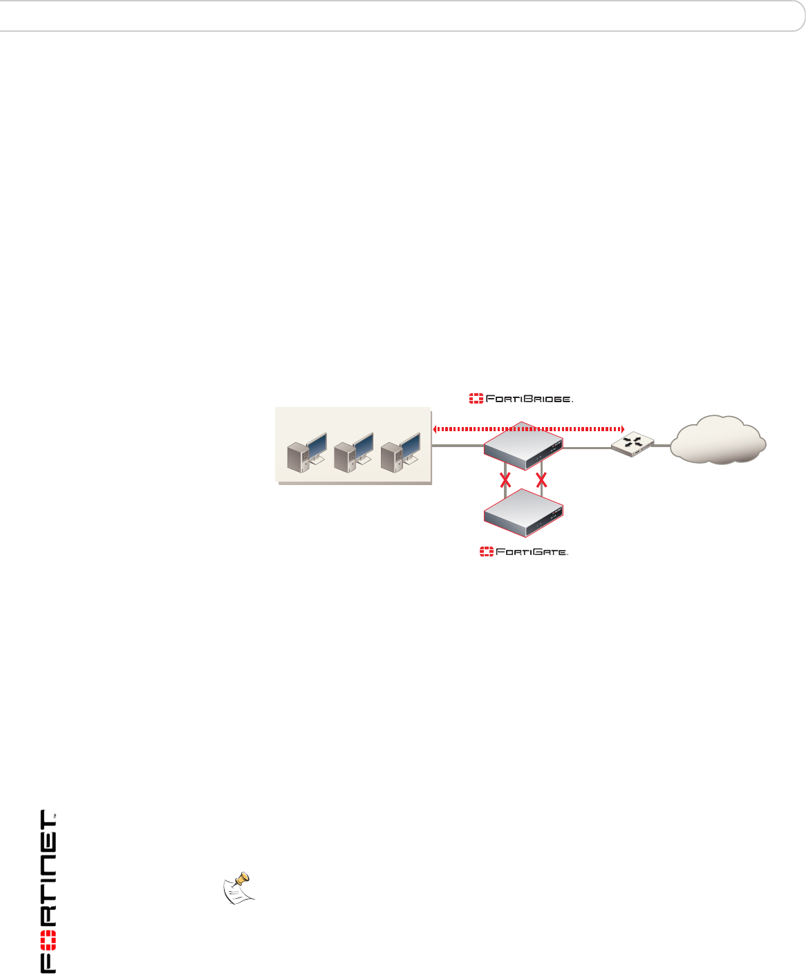
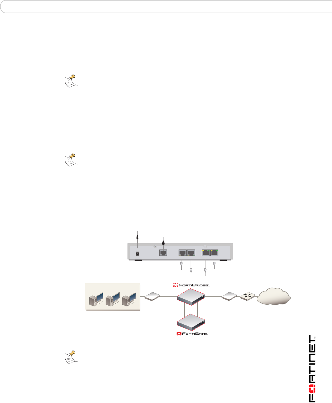
Figure 3: FortiBridge unit providing fail open protection
Connecting the FortiBridge-1000 (copper gigabit ethernet)
The FortiBridge-1000 unit contains 4 auto-sensing 10/100/1000 Ethernet
interfaces that connect to the internal and external networks and to the FortiGate
interfaces that were connected to these networks. Use the following steps to
connect a FortiBridge-1000 unit to the network as shown in Figure 3.
Router
INT 1
INT 2
EXT 1
EXT 2
Internal External
Internal network
Internet
(Transparent mode)
(Normal mode)
Note: Normally, you would use straight-through ethernet cables to connect the
FortiBridge-1000 unit to the FortiGate unit and to your networks. However, for some
connections you may need a crossover ethernet cable (for example, for compatibility with
network devices that do not support Auto MDI/MDIX).
FortiBridge operating principles Normal mode operation
FortiBridge Version 3.0 Administration Guide
09-30000-0163-20061109 11
1Connect the FortiBridge-1000 INT 2 interface to the FortiGate internal interface.
2Connect the FortiGate external interface to the FortiBridge-1000 EXT 2 interface.
3Connect the internal network to the FortiBridge-1000 INT 1 interface.
4Connect the FortiBridge-1000 EXT 1 interface to the router.
Connecting the FortiBridge-1000F (fiber gigabit ethernet)
The FortiBridge-1000F unit contains 4 multimode fiber optic gigabit interfaces that
connect to the internal and external networks and to the FortiGate interfaces that
were connected to these networks. Use the following steps to connect a
FortiBridge-1000F unit to the network as shown in Figure 3.
1Connect the FortiBridge-1000F INT 2 interface to the FortiGate internal interface.
2Connect the FortiGate external interface to the FortiBridge-1000F EXT 2
interface.
3Connect the internal network to the FortiBridge-1000F INT 1 interface.
4Connect the FortiBridge-1000F EXT 1 interface to the router.
Normal mode operation
If the FortiGate unit is operating normally, the FortiBridge unit operates in Normal
mode. Traffic from the internal network enters the FortiBridge INT 1 interface then
exits the INT 2 interface to the FortiGate unit. The traffic from the FortiBridge
INT 2 interface enters the FortiGate internal interface. Firewall policies and
protection profiles are applied to the traffic by the FortiGate unit. Accepted traffic
then exits the FortiGate External interface and enters the FortiBridge EXT 2
interface. The traffic then exits the FortiBridge EXT 1 interface and goes to the
external network. Traffic from the external network reverses this sequence.
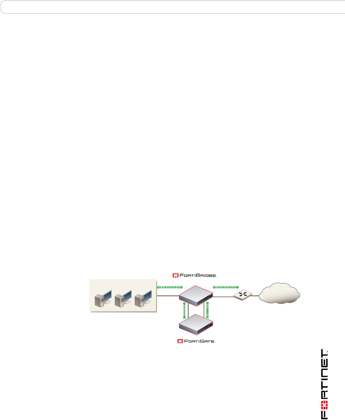
Figure 4: Normal mode traffic flow
How the FortiBridge unit monitors the FortiGate unit
To monitor the FortiGate unit for failure, you must enable probes on the
FortiBridge unit. When you enable a probe, the FortiBridge unit sends packets
from the FortiBridge INT 2 interface, through the FortiGate unit to the FortiBridge
EXT 2 interface. If the EXT 2 interface receives the probe packets, the FortiGate
unit is operating normally. If the EXT 2 interface does not receive probe packets
the FortiBridge unit assumes that the FortiGate unit has failed.
Router
INT 1
INT 2
EXT 1
EXT 2
Internal External
Internal network
Internet
(Transparent mode)
(Normal mode)
FortiBridge Version 3.0 Administration Guide
12 09-30000-0163-20061109
Normal mode operation FortiBridge operating principles
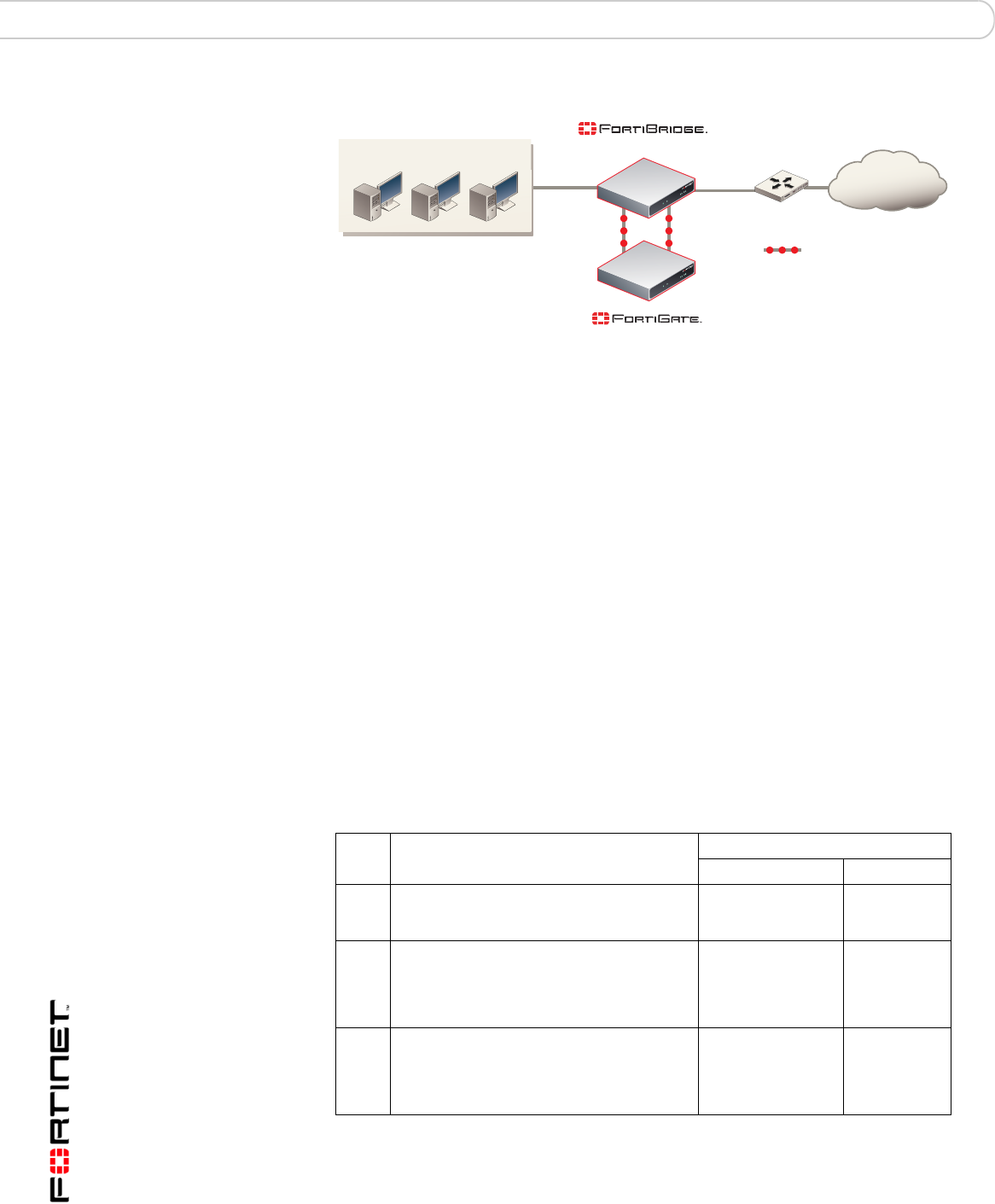
Figure 5: FortiBridge unit operating in normal mode sending probe packets
You can enable ICMP (ping), HTTP, FTP, POP3, SMTP, and IMAP probes to test
connectivity through the FortiGate unit for each of these protocols. The
FortiBridge unit simultaneously tests connectivity through the FortiGate unit for
each probe that is enabled.
The first probe that registers a failure causes the FortiBridge unit to stop sending
all probe packets. The FortiBridge unit responds to the failure according to the
action on failure that you configure. The action on failure can include fail open,
send alert email, send a syslog message, and send an SNMP trap. You can
enable any combination of these actions on failure. Fail open switches the
FortiBridge unit to bypass mode. Other actions on failure alert system
administrators that the FortiBridge has determined that a failure occurred.
Probes and FortiGate firewall policies
Probe packets are accepted and passed through the FortiGate unit by firewall
policies added to the FortiGate unit. When enabling probes, you must make sure
that the firewall policies added to the FortiGate unit can accept probe packets. For
example, if your FortiGate unit does not accept FTP packets, you should not
enable the FTP probe. Table 1 describes FortiGate firewall policy requirements for
each FortiBridge probe.
Router
INT 1
INT 2
EXT 1
EXT 2
Internal External
Probe packets
Internal network
Internet
(Transparent mode)
(Normal mode)
Table 1: FortiBridge probes and FortiGate firewall policy requirements
Probe Description
FortiGate Firewall policy
Direction Service
Ping ICMP packets are sent from the INT 2
interface to the EXT 2 interface. The EXT 2
interface responds to the ping.
Internal -> External ICMP or ANY
HTTP HTTP requests are sent from an HTTP
client at the INT 2 interface to a web server
at the EXT 2 interface. The web server
sends a response from the EXT 2 interface
to the INT 2 interface.
Internal -> External HTTP or ANY
FTP FTP requests are sent from an FTP client at
the INT 2 interface to an FTP server at the
EXT 2 interface. The FTP server sends a
response from the EXT 2 interface to the
INT 2 interface.
Internal -> External FTP or ANY

FortiBridge operating principles Normal mode operation
FortiBridge Version 3.0 Administration Guide
09-30000-0163-20061109 13
Enabling probes to detect FortiGate hardware failure
A FortiGate unit can stop processing network traffic because of a hardware failure
such as the failure of a hardware component, a loss of power, or a loss of
connectivity if a network cable is unplugged.
If a hardware failure occurs, the FortiGate unit stops processing all traffic. You can
enable any FortiBridge probe for the FortiBridge unit to detect a FortiGate
hardware failure.
Enabling probes to detect FortiGate software failure
A FortiGate unit can also stop processing network traffic because of a software
failure. For example, a firmware issue could cause a specific software process to
crash. Also, network traffic could increase to a point where the FortiGate unit
cannot process all traffic. As a result, the FortiGate unit could stop processing
some or all traffic without a hardware failure occurring.
To detect a FortiGate software failure, you can enable probes for FortiGate
services that you want to provide fail open protection for. For example, if it is a
high priority for your network to provide SMTP email services, you should enable
the SMTP probe. If the SMTP probe detects a failure of SMTP traffic through the
FortiGate unit, the FortiBridge unit switches to bypass mode to maintain SMTP
traffic flow.
If you do not consider FTP traffic a high priority, you can leave the FTP probe
disabled. In this configuration, if only FTP traffic fails, the FortiBridge does not
switch to bypass mode.
Probe interval and probe threshold
For each probe, you set a probe interval and a probe threshold. The probe interval
defines how often to test the connection. The probe threshold defines how many
consecutive failed probes can occur before the FortiBridge considers the
connection to have failed.
POP3 POP3 packets are sent from a POP3 client
at the INT 2 interface to a POP3 server at
the EXT 2 interface. The POP3 server
sends a response from the EXT 2 interface
to the INT 2 interface.
Internal -> External POP3 or ANY
SMTP SMTP packets are sent from an SMTP
server at the INT 2 interface to an SMTP
server at the EXT 2 interface. The SMTP
server sends a response from the EXT 2
interface to the INT 2 interface.
Internal -> External SMTP or ANY
IMAP IMAP packets are sent from an IMAP client
at the INT 2 interface to an IMAP server at
the EXT 2 interface. The IMAP server sends
a response from the EXT 2 interface to the
INT 2 interface.
Internal -> External IMAP or ANY
Table 1: FortiBridge probes and FortiGate firewall policy requirements (Continued)
Probe Description
FortiGate Firewall policy
Direction Service
FortiBridge Version 3.0 Administration Guide
14 09-30000-0163-20061109
Bypass mode operation FortiBridge operating principles
Bypass mode operation
When the FortiBridge unit operates in bypass mode, the FortiBridge INT 1 and
EXT 1 interfaces are directly connected. All traffic between the internal and
external network segments flows, whether or not the FortiGate unit is operating
normally.
Because the INT 1 and EXT 1 interfaces are directly connected, you cannot use
Telnet or SSH to connect to the FortiBridge CLI. Instead you must use a console
connection.
The FortiBridge unit remains in bypass mode even if the FortiGate unit recovers.
To restore the FortiGate unit, you must manually switch the FortiBridge unit back
to normal mode. You can switch the FortiBridge unit to normal mode by pressing
the mode switch on the FortiBridge front panel or by using a console connection to
the CLI and entering the command execute switch-mode. You can also use
the mode switch and the execute switch-mode command to manually switch
the FortiBridge unit from normal mode to bypass mode.
Figure 6: FortiBridge unit operating in bypass mode
When the FortiBridge unit is operating in bypass mode you can still connect to the
FortiBridge CLI and manage the FortiBridge unit (for example to switch the
FortiBridge unit to normal mode). When the FortiBridge unit operates in bypass
mode, you cannot connect to the FortiGate interfaces that are connected to the
FortiBridge unit.
FortiBridge power failure
If a power failure occurs and the FortiBridge unit loses power, zero power fail open
technology causes FortiBridge unit to fail open. The FortiBridge unit bypasses the
FortiGate unit and all traffic passes between the FortiBridge INT 1 and EXT 1
interfaces. If power is restored to the FortiBridge unit, it starts up in bypass mode
and then switches to normal mode when its start up sequence is complete,
reconnecting the FortiGate unit to the network.
Router
INT 1
INT 2
EXT 1
EXT 2
Internal External
Internal network
Internet
(Transparent mode)
(Bypass mode)
Note: The FortiBridge-1000F contains a battery to keep the fibers lit in fail open mode. If
the FortiBridge-1000F unit loses power, the battery will power the fail open condition for
approximately three hours. When power is restored, the battery requires approximately
three hours to recharge if completely drained. The FortiBridge-1000 unit does not use a
battery and can maintain a fail open condition indefinitely.
FortiBridge operating principles Example FortiGate HA cluster FortiBridge application
FortiBridge Version 3.0 Administration Guide
09-30000-0163-20061109 15
Example FortiGate HA cluster FortiBridge application
A FortiBridge unit can provide fail open protection for a FortiGate HA cluster
operating in transparent mode in much the same way as for a standalone
FortiGate unit. To provide fail open protection for an HA cluster, connect the
FortiBridge unit to the switches that connect the internal and external interfaces of
the cluster. Use the following steps to connect a FortiBridge unit to the HA cluster,
as shown in Figure 7:
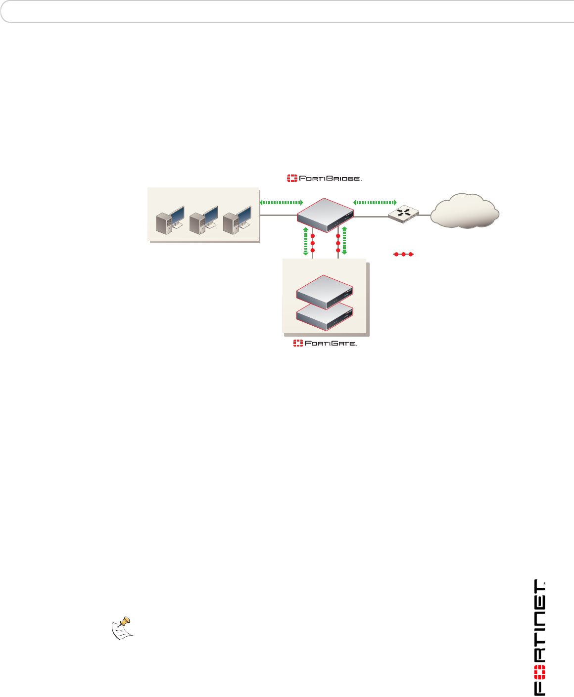
Figure 7: FortiBridge unit providing fail open protection for a FortiGate HA cluster
The network configuration and FortiBridge configuration are the same for a cluster
and for a standalone FortiGate unit. In normal mode, packets pass through the
FortiBridge unit and through the FortiGate HA cluster and back through the
FortiBridge unit. For the cluster to process this traffic, you must add
Internal -> External firewall policies to the cluster configuration. If a failure occurs
and the cluster no longer processes traffic, the FortiBridge unit switches to bypass
mode, bypassing the cluster.
The connection procedure is different depending on whether the FortiBridge unit
uses copper gigabit ethernet network connections or fiber gigabit ethernet
network connections. This section includes the following connection procedures:
•Connecting the FortiBridge-1000 (copper gigabit ethernet)
•Connecting the FortiBridge-1000F (fiber gigabit ethernet)
Connecting the FortiBridge-1000 (copper gigabit ethernet)
The FortiBridge-1000 unit contains 4 auto-sensing 10/100/1000 Ethernet
interfaces that connect to the internal and external networks and to the cluster
interfaces that were connected to these networks. Use the following steps to
connect a FortiBridge-1000 unit to the network as shown in Figure 7.
Router
INT 1
INT 2
EXT 1
EXT 2
Internal External
Internal network
Internet
(Transparent mode)
(Normal mode)
HA cluster
Probe packets
Note: Normally, you would use straight-through ethernet cables to connect the
FortiBridge-1000 unit to the FortiGate unit and to your networks. However, for some
connections you may need a crossover ethernet cable (for example, for compatibility with
network devices that do not support Auto MDI/MDIX).
FortiBridge Version 3.0 Administration Guide
16 09-30000-0163-20061109
Example configuration with other FortiGate interfaces FortiBridge operating principles
1Connect the FortiBridge-1000 INT 2 interface to the switch connected to the HA
cluster internal interface.
2Connect the switch connected to the HA cluster external interface to the
FortiBridge-1000 EXT 2 interface.
3Connect the internal network to the FortiBridge-1000 INT 1 interface.
4Connect the FortiBridge-1000 EXT 1 interface to the router.
Connecting the FortiBridge-1000F (fiber gigabit ethernet)
The FortiBridge-1000F unit contains 4 multimode fiber optic gigabit interfaces that
connect to the internal and external networks and to the FortiGate cluster
interfaces that were connected to these networks. Use the following steps to
connect a FortiBridge-1000F unit to the network as shown in Figure 3.
1Connect the FortiBridge-1000F INT 2 interface to the switch connected to the HA
cluster internal interface.
2Connect the switch connected to the HA cluster external interface to the
FortiBridge-1000F EXT 2 interface.
3Connect the internal network to the FortiBridge-1000F INT 1 interface.
4Connect the FortiBridge-1000F EXT 1 interface to the router.
Example configuration with other FortiGate interfaces
All of the examples in this chapter describe using the FortiBridge unit to provide
fail open protection for traffic passing between the FortiGate unit internal and
external interfaces. You can actually use a FortiBridge unit to provide fail open
protection for any two FortiGate unit interfaces. No limitation is implied by naming
the FortiBridge interfaces INT and EXT. These names are used to simplify
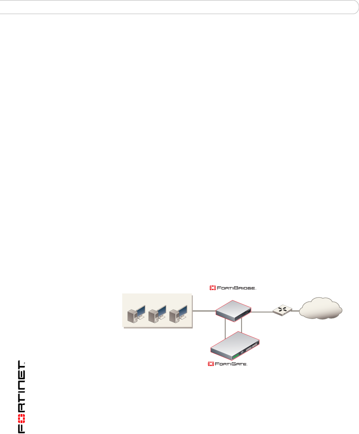
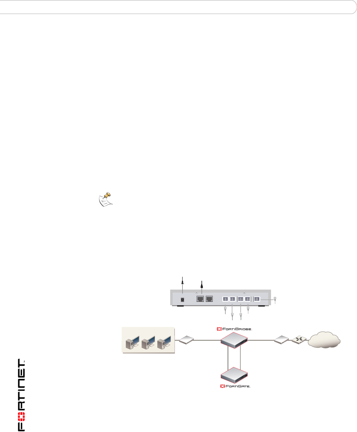
installation procedures. Figure 8 shows a FortiBridge-1000 unit providing fail open
protection for network traffic between ports 5 and 6 of a FortiGate-500A unit.
Figure 8: FortiBridge unit providing fail open protection for a single FortiGate unit
To connect a FortiBridge-1000 unit to the network shown in Figure 8:
1Connect the FortiBridge-1000 INT 2 interface to the FortiGate-500A port 5
interface.
2Connect the FortiGate-500A port 6 interface to the FortiBridge-1000 EXT 2
interface.
Router
INT 1
INT 2
EXT 1
EXT 2
Port 5 Port 6
Internal network
Internet
(Trans
p
arent mode)
(Normal mode)
-500A

FortiBridge operating principles Example configuration with other FortiGate interfaces
FortiBridge Version 3.0 Administration Guide
09-30000-0163-20061109 17
3Connect the internal network to the FortiBridge-1000 INT 1 interface.
4Connect the FortiBridge-1000 EXT 1 interface to the router.
You must add port 5 -> port 6 firewall policies to the FortiGate-500A unit
configuration.

FortiBridge Version 3.0 Administration Guide
18 09-30000-0163-20061109
Example configuration with other FortiGate interfaces FortiBridge operating principles

Setting up FortiBridge units FortiBridge unit basic information
FortiBridge Version 3.0 Administration Guide
09-30000-0163-20061109 19
Setting up FortiBridge units
This chapter contains the information you need to unpack, connect, and configure
your FortiBridge unit:
•FortiBridge unit basic information
•Connecting and turning on the FortiBridge unit
•Connecting to the command line interface (CLI)
•Completing the basic FortiBridge configuration
•Resetting to the factory default configuration
•Installing FortiBridge unit firmware
When you complete the procedures in this chapter, the FortiBridge unit will be
operating and connected to your network and to your FortiGate unit. See
“Configuration and operating procedures” on page 35 to configure the FortiBridge
unit to monitor the status of the FortiGate unit and to fail open if the FortiBridge
unit detects that the FortiGate unit has failed.
FortiBridge unit basic information
This section describes the following basic information about the FortiBridge units:
•FortiBridge-1000 Package contents
•Mounting instructions
•Technical specifications
•LED indicators
•Connectors
•Factory default configuration
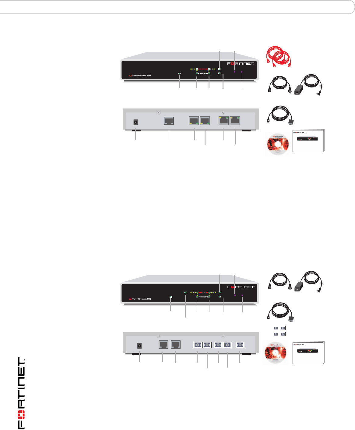
FortiBridge-1000 Package contents
The FortiBridge-1000 package contains the following items:
• the FortiBridge-1000 unit
• two orange crossover Ethernet cables (Fortinet part number CC300248)
• one RJ-45 to DB-9 serial cable (Fortinet part number CC300302)
• FortiBridge-1000 QuickStart Guide
• CD containing the Fortinet user documentation
• one AC adapter
FortiBridge Version 3.0 Administration Guide
20 09-30000-0163-20061109
FortiBridge unit basic information Setting up FortiBridge units
Figure 9: FortiBridge-1000 package contents
FortiBridge-1000F Package contents
The FortiBridge-1000F package contains the following items:
• the FortiBridge-1000F unit
• one RJ-45 to DB-9 serial cable (Fortinet part number CC300302)
• four 1000Base-SX SFP Transceivers
• FortiBridge QuickStart Guide
• CD containing the Fortinet user documentation
• one AC adapter
Figure 10: FortiBridge-1000F package contents
Mounting instructions
Install the FortiBridge unit on any stable surface. Make sure that the unit has at
least 1.5 in. (3.75 cm) of clearance on each side to allow for adequate air flow and
cooling.
PWR STATUS
PWR
INT 1
INT 2 NORMAL
EXT 2
EXT 1 BYPASS MODE MODE FACTORY RESET
FortiGate
Esc Enter
INT 2
EXT 2
DC+5V
PWR CONSOLE
TO FORTIGATE
INT 1EXT 1
Power
Change
Mode
Factory
Reset
Bypass
Mode
Normal
Mode
INT 1
INT 2
EXT 1
EXT 2
2 Orange Crossover
Ethernet Cables
USER MANUAL
FortiBridge-1000
QuickStart Guide
Copyright 2005 Fortinet Incorporated. All rights reserved.
Trademarks
Products mentioned in this document are trademarks.
Power Cable Power Supply
RJ-45 to
DB-9 Serial Cable
Power
FortiGate unit
connections Network
connections
Console
Connection
Front
Back
EXT 2
INT 2
EXT 1
INT 1
PWR
INT 1
INT 2 NORMAL
EXT 2
EXT 1 BYPASS MODE MODE FACTORY RESET
FortiGate
EscEnter
Documentation
Management
Management
Factory
Reset
Normal
Mode
INT 1
INT 2
EXT 1
EXT 2
EXT 2INT 2
DC+5V
PWR CONSOLE MODEM
TO FORTIGATE
EXT 1 MANAGEMENT
INT 1
PWR
INT 1
INT 2
MANAGEMENT
NORMAL
EXT 2
EXT 1 BYPASS MODE MODE
FFortiGate
Esc Enter
FACTORY RESET
Power
Change
Mode
Bypass
Mode
FortiBridge-1000
QuickStart Guide
Copyright 2005 Fortinet Incorporated. All rights reserved.
Trademarks
Products mentioned in this document are trademarks.
Power Cable Power Supply
RJ-45 to
DB-9 Serial Cable
Power
FortiGate unit
connections
Network
connections
Console
Front
Back
INT 2
EXT 2
Modem INT 1
EXT 1
PWR
INT 1
INT 2 NORMAL
EXT 2
EXT 1 BYPASS MODE MODE FACTORY RESET
FortiGate
EscEnter
Documentation
4 1000Base-SX
SFP Transceivers

Setting up FortiBridge units FortiBridge unit basic information
FortiBridge Version 3.0 Administration Guide
09-30000-0163-20061109 21
Technical specifications
LED indicators
Table 2: FortiBridge-1000 and 1000F technical specifications
Dimensions 8.63 x 6.13 x 1.38 in. (21.9 x 15.6 x 3.5 cm)
Weight 1.5 lb. (0.68 kg)
Power
Requirements DC input voltage: 5 V
DC input current: 5 A
Environmental
specifications Operating temperature: 32 to 104°F (0 to 40°C)
Storage temperature: -13 to 158°F (-25 to 70°C)
Humidity: 5 to 95% non-condensing
Table 3: FortiBridge-1000 LED indicators
LED State Description
PWR Green The FortiBridge unit is powered on.
Off The FortiBridge unit is powered off.
INT 1
INT 2
EXT 1
EXT 2
Green The correct cable is in use and the connected equipment
has power.
Flashing Green Network activity at this interface.
Off No link established or the interface has been turned off.
INT 1
INT 2
EXT 1
EXT 2
(back)
Green The correct cable is in use, and the connected equipment
has power.
Flashing amber Network activity at this interface.
Off No link established.
Table 4: FortiBridge-1000F LED indicators
LED State Description
PWR Green The FortiBridge unit is powered on.
Off The FortiBridge unit is powered off.
INT 1,
INT 2,
EXT 1, and
EXT 2
Green The correct optical fiber patch cable is connected to the
gigabit fiber interface.
Flashing Network activity at the gigabit fiber interface.

FortiBridge Version 3.0 Administration Guide
22 09-30000-0163-20061109
FortiBridge unit basic information Setting up FortiBridge units
Connectors
Factory default configuration
Table 5: FortiBridge-1000 connectors
Connector Type Speed Protocol Description
INT 1 RJ-45 10/100/1000
Base-T
Ethernet Copper gigabit ethernet connection to the internal
network.
EXT 1 RJ-45 10/100/1000
Base-T
Ethernet Copper gigabit ethernet connection to the
external network.
INT 2 RJ-45 10/100/1000
Base-T
Ethernet Copper gigabit ethernet connection to the
FortiGate unit internal interface.
EXT 2 RJ-45 10/100/1000
Base-T
Ethernet Copper gigabit ethernet connection to the
FortiGate unit external interface.
CONSOLE RJ-45 9600 bps RS-232
serial
Optional connection to the management
computer.
Provides access to the command line interface
(CLI).
Table 6: FortiBridge-1000F connectors
Connector Type Speed Protocol Description
INT 1, INT 2,
EXT 1,
EXT 2, and
management
LC SFP 1000Base-SX Ethernet Multimode fiber optic connections
to gigabit optical networks. The
FortiBridge-1000F is shipped with
4 1000Base-SX Small Formfactor
Pluggable (SFP) transceivers that
you must insert into the INT 1, INT
2, EXT 1, and EXT 2 sockets on
the back panel. The management
connection is optional.
CONSOLE RJ-45 9600 bps RS-232
serial Console connection to the
command line interface (CLI).
Table 7: FortiBridge-1000 and 1000F unit factory default network configuration
Administrator account admin
Password (none)
Management IP/Netmask 192.168.1.99/255.255.255.0
Management Access Telnet, SSH and ping access to the INT 1
interface. No management access to the EXT 1
interface.
Routes (none)
Primary DNS 65.39.139.53
Secondary DNS 65.39.139.63
Setting up FortiBridge units Connecting and turning on the FortiBridge unit
FortiBridge Version 3.0 Administration Guide
09-30000-0163-20061109 23
Connecting and turning on the FortiBridge unit
In most cases, you can connect the FortiBridge unit without making any
configuration changes to your network or your FortiGate unit. All that is required is
to move and reconnect network cables.
Right out of the box you can connect, power on, and configure the FortiBridge unit
without interrupting network traffic (except for the interruption required to move
and re-connect network cables). When connected and powered on, the
FortiBridge unit operates in Normal mode. Probes are not configured. The
FortiBridge unit does not provide fail open protection until probes are configured.
Connecting and turning on the FortiBridge-1000 unit
The FortiBridge-1000 unit contains 4 auto-sensing 10/100/1000 Ethernet
interfaces that connect to the internal and external networks and to the FortiGate
interfaces that were connected to these networks. Use the following steps to
connect a FortiBridge-1000 unit to the network as shown in Figure 11.
Figure 11: Connecting the FortiBridge-1000 unit
Note: The default FortiBridge management IP address is 192.168.1.99. If this IP address
conflicts with an IP address on your network, you can use the procedure “Changing the
management IP address” on page 27 to change this IP address.
Note: This procedure describes how to connect a FortiBridge-1000 unit to provide fail open
protection for network traffic passing between FortiGate unit internal and external
interfaces. If the FortiBridge-1000 unit provides fail open protection for traffic between
different FortiGate interfaces, you can use the same procedure but substitute FortiGate
interface names as required.
Router
INT 1
INT 2
EXT 1
EXT 2
Internal External
(Trans
p
arent mode)
Internal network
Internet
Switch Switch
INT 2
EXT 2
DC+5V
PWR CONSOLE
TO FORTIGATE
INT 1EXT 1
Ethernet connection to FortiGate Internal interface
Power cable connects to power supply
Ethernet connection to FortiGate External interface
Ethernet connection to External network
Ethernet connection to Internal network
Optional RJ-45 serial cable connects to management computer
Note: Normally, you would use straight-through ethernet cables to connect the
FortiBridge-1000 unit to the FortiGate unit and to your networks. However, for some
connections you may need a crossover ethernet cable (for example, for compatibility with
network devices that do not support Auto MDI/MDIX).
FortiBridge Version 3.0 Administration Guide
24 09-30000-0163-20061109
Connecting and turning on the FortiBridge unit Setting up FortiBridge units
To connect and turn on the FortiBridge-1000 unit
1Connect the FortiBridge-1000 INT 2 interface to the FortiGate unit internal
interface.
2Connect the FortiBridge-1000 EXT 2 interface to the FortiGate unit external
interface.
3Connect the FortiBridge-1000 INT 1 interface to the internal network.
4Connect the FortiBridge-1000 EXT 1 interface to the external network.
5Turn on the FortiGate unit and any network equipment that was turned off.
6Connect the AC adapter to the power connection at the back of the
FortiBridge-1000 unit and to a power outlet.
The FortiBridge-1000 unit starts. The PWR and Bypass Mode LEDs turn on. After
a short time, the FortiBridge unit switches to Normal mode. The Bypass LED goes
out and the Normal LED turns on.
If the FortiGate unit and connected network components are turned on the
FortiBridge-1000 INT 1, INT 2, EXT 1, and EXT 2 LEDs are also on.
Connecting and turning on the FortiBridge-1000F unit
The FortiBridge-1000F unit contains 4 multimode fiber optic gigabit interfaces that
connect to the internal and external networks and to the FortiGate interfaces that
were connected to these networks. Use the following steps to connect a
FortiBridge-1000F unit to the network as shown in Figure 12.
Figure 12: Connecting the FortiBridge-1000F unit
To connect and turn on the FortiBridge-1000F unit
1Connect the FortiBridge-1000F INT 2 interface to the FortiGate internal interface.
2Connect the FortiGate external interface to the FortiBridge-1000F EXT 2 interface.
Note: This procedure describes how to connect a FortiBridge-1000F unit to provide fail
open protection for network traffic passing between FortiGate unit internal and external
interfaces. If the FortiBridge-1000F unit provides fail open protection for traffic between
different FortiGate interfaces, you can use the same procedure but substitute FortiGate
interface names as required.
EXT 2INT 2
DC+5V
PWR CONSOLE MODEM
TO FORTIGATE
EXT 1 MANAGEMENT
INT 1
Router
INT 1
INT 2
EXT 1
EXT 2
Internal
Gigabit
Fiber
Gigabit
Fiber
Gigabit
Fiber
Gigabit
Fiber
External
(Transparent mode)
Internal network
Internet
Switch Switch
Gigabit Fiber connection to FortiGate External interface
Power cable connects to power supply
Gigabit Fiber connection to FortiGate Internal interface
Gigabit Fiber connection to Internal network
Gigabit Fiber connection to External network
Optional Gigabit Fiber connection
for out of band management
Optional RJ-45 serial cable connects to management computer

Setting up FortiBridge units Connecting to the command line interface (CLI)
FortiBridge Version 3.0 Administration Guide
09-30000-0163-20061109 25
3Connect the internal network to the FortiBridge-1000F INT 1 interface.
4Connect the FortiBridge-1000F EXT 1 interface to the router.
Connecting to the command line interface (CLI)
You configure and manage the FortiBridge unit from the FortiBridge command line
interface (CLI). You can use a direct console connection, SSH, or Telnet to
connect to the FortiBridge CLI. This section describes how to connect directly to
the FortiBridge console and how to connect to the FortiBridge CLI across an
ethernet network using Telnet. See also “Connecting to the FortiBridge CLI using
Telnet” on page 26 for more information about connecting to the FortiBridge CLI.
Connecting to the FortiBridge console
You require:
• A computer with an available communications port,
• An RJ-45 to DB-9 serial cable,
• Terminal emulation software such as HyperTerminal for Windows.
To connect to the FortiBridge console for the first time
1Connect the FortiBridge console port to the available communications port on
your computer.
2Make sure the FortiBridge unit is powered on.
3Start HyperTerminal, enter a name for the connection, and select OK.
4Configure HyperTerminal to connect directly to the communications port on the
computer to which you have connected the FortiBridge console port.
5Select OK.
6Select the following port settings and select OK.
7Press the escape key (Esc) to connect to the FortiBridge CLI.
A prompt similar to the following appears (shown for the FortiBridge-1000):
FortiBridge-1000 login:
8Type a valid administrator name and press Enter.
The default administrator account is admin.
Note: The following procedure describes how to connect to the FortiBridge CLI using
Windows HyperTerminal software. You can use any terminal emulation software.
Bits per second 9600
Data bits 8
Parity None
Stop bits 1
Flow control None

FortiBridge Version 3.0 Administration Guide
26 09-30000-0163-20061109
Completing the basic FortiBridge configuration Setting up FortiBridge units
9Type the password for this administrator and press Enter.
The default admin account does not require a password. For improved security,
you should add a password for this account as soon as possible. Use the
procedure “Adding an administrator password” on page 27 to add a password.
The following prompt appears:
Welcome !
FortiBridge-1000 #
You have connected to the FortiBridge CLI, and you can enter CLI commands.
Connecting to the FortiBridge CLI using Telnet
By default, you can use a Telnet client running on a management computer to
connect to the FortiBridge CLI. The management computer must be connected to
the same network as the FortiBridge INT 1 interface.
The default FortiBridge management IP address is 192.168.1.99. Your
management PC should be configured to connect to this IP address. Alternatively,
you can connect to the FortiBridge console and use the procedure “Changing the
management IP address” on page 27 to change the management IP address.
To connect to the CLI using Telnet
1On the management computer, Telnet to the IP address 192.168.1.99.
If you have changed the management IP address, Telnet to this address instead.
2Type a valid administrator name and press Enter.
The default administrator account is admin.
3Type the password for this administrator and press Enter.
The default admin account does not require a password. For improved security,
you should add a password for this account as soon as possible. Use the
procedure “Adding an administrator password” on page 27 to add a password.
The following prompt appears:
Welcome !
FortiBridge-1000 #
You have connected to the FortiBridge CLI, and you can enter CLI commands.
Completing the basic FortiBridge configuration
Now that you have connected the FortiBridge unit to your network and connected
to the FortiBridge CLI, use the following procedures to complete the basic
configuration of the FortiBridge unit.
Note: A maximum of 5 Telnet connections to the FortiBridge unit can be open at the same
time.

Setting up FortiBridge units Completing the basic FortiBridge configuration
FortiBridge Version 3.0 Administration Guide
09-30000-0163-20061109 27
•Adding an administrator password
•Changing the management IP address
•Changing DNS server IP addresses
•Adding static routes
•Allowing management access to the EXT 1 interface
•Changing the system time and date
•Adding administrator accounts
Adding an administrator password
Add an administrator password to the default admin administrator account to
prevent unauthorized users from connecting to and managing the FortiBridge unit.
To add an administrator password
1Log in to the CLI.
2Change the admin administrator password. Enter:
config system admin
edit admin
set password <psswrd>
end
For example:
config system admin
edit admin
set password passWORD
end
Changing the management IP address
Change the FortiBridge unit management IP address so that you can connect to
the FortiBridge CLI from your network (instead of being required to use a direct
console connection). The management IP should be a valid IP address for your
network.
To change the management IP address
1Log in to the CLI.
2Change management IP address. Enter:
config system manageip
set ip <address_ipv4mask>
end
For example:
config system manageip
set ip 192.168.20.23/24
end
Note: Not all of the following procedures are required to complete the basic FortiBridge unit
configuration. Choose the procedures that apply to your installation.

FortiBridge Version 3.0 Administration Guide
28 09-30000-0163-20061109
Completing the basic FortiBridge configuration Setting up FortiBridge units
Changing DNS server IP addresses
Change the FortiBridge DNS server IP addresses to the IP addresses of your
DNS servers. The correct DNS server configuration is required for alert email.
To change DNS server IP addresses
1Log in to the CLI.
2Change the primary and secondary DNS server IP addresses. Enter:
config system dns
set primary <address_ipv4>
set secondary <address_ipv4>
end
For example:
config system dns
set primary 192.168.30.23
set secondary 192.168.30.24
end
Adding static routes
Add static routes if you need to route packets from the FortiBridge unit through a
router to another network. For example, if alert email sends email messages from
the internal network to an email server on the Internet, you should add a route to
the Internet.
To add static routes
1Log in to the CLI.
2Add the default route. Enter:
config system route
edit <sequence_integer>
set gateway <gateway-address_ipv4>
end
For example:
config system route
edit 1
set gateway 192.168.20.1
end
3If required for your network configuration, add a static route. Enter:
config system route
edit <sequence_integer>
set gateway <gateway-address_ipv4>
set dst <destination-address_ipv4mask>
end
For example:
config system route
edit 2
set gateway 192.168.20.3
set dst 192.168.22.0 255.255.255.0
end

Setting up FortiBridge units Completing the basic FortiBridge configuration
FortiBridge Version 3.0 Administration Guide
09-30000-0163-20061109 29
Allowing management access to the EXT 1 interface
By default no management access is configured for the EXT 1 interface. Use the
following procedure to add management access to this interface if required.
To allow management access to the EXT 1 interface
1Log in to the CLI.
2Allow Telnet and ping management access to the EXT 1 interface. Enter:
config system interface external
set allowaccess telnet ping
end
Changing the system time and date
Use the following procedure to change the system time and date.
To change the system time and date
1Log in to the CLI.
2Change the system time. Enter:
execute time <hh:mm:ss>
For example:
execute time 12:24:34
3Change the system date. Enter:
execute date <mm/dd/yyyy>
For example:
execute date 04/26/2005
4Change the FortiBridge system time zone. Enter:
config system global
set timezone <timezone_integer>
end
Enter the number corresponding to your time zone. Type ? to list time zones and
their numbers. Choose the time zone from the list and enter the correct number.
For example, to set the time zone to Central time (time zone number 8), enter:
config system global
set timezone 8
end
For information about configuring other global settings, see “system global” on
page 66.
Adding administrator accounts
The factory default FortiBridge configuration includes the admin administrator
account. Use this procedure to add more administrator accounts.
To add administrator accounts
1Log in to the CLI.
2Add an administrator. Enter:

FortiBridge Version 3.0 Administration Guide
30 09-30000-0163-20061109
Resetting to the factory default configuration Setting up FortiBridge units
config system admin
edit <admin_name_str>
set password <password>
set accprofile prof_admin
end
For example:
config system admin
edit new_admin
set password p8ssw0rd
set accprofile prof_admin
end
For more information about configuring administrators see “system admin” on
page 59.
Resetting to the factory default configuration
Use the following procedure to reset the FortiBridge unit to the factory default
configuration. You might want to rest the FortiBridge to the factory default
condition if the FortiBridge unit is not functioning as expected and you would like
to re-start the configuration process. Resetting to the factory default configuration
resets all configuration changes that you have made, including the management
IP address. See “Factory default configuration” on page 22.
To reset to factory default configuration from the FortiBridge front panel
1Press and release the Factory reset button.
Use a pen or other pointed object to press the button.
After a few seconds the FortiBridge unit restarts; reset to the factory default
configuration. You can now re-configure the FortiBridge unit.
To reset to factory defaults from the FortiBridge CLI
1Log into the CLI.
2Enter the following command:
execute factoryreset
3Type y and press Enter.
After a few seconds the FortiBridge unit restarts; reset to the factory default
configuration. You can now re-configure the FortiBridge unit.
Installing FortiBridge unit firmware
Select a procedure from Table 8 to install FortiBridge unit firmware.
Before beginning any of the procedures in this section, you must have the
FortiBridge firmware image file that you are going to install on the FortiBridge unit.
During these procedures you are required to enter the name of the firmware
image file.

Setting up FortiBridge units Installing FortiBridge unit firmware
FortiBridge Version 3.0 Administration Guide
09-30000-0163-20061109 31
Upgrading to a new firmware version
You cannot use this procedure to re-install the current firmware or to revert to an
older version of the firmware. If you need to re-install the current firmware or
revert to an older firmware version, see “Reverting to a previous firmware version”
on page 32.
The following procedure requires a TFTP server that you can connect to from the
FortiBridge unit.
To upgrade to a new firmware version
1Make sure that the TFTP server is running.
2Copy the new firmware image file to the root directory of your TFTP server.
3Log into the CLI as an administrator with sysshutdowngrp access.
Normally this would be the admin administrator. But you can use access profiles
to control administrative access. See “system accprofile” on page 57 for more
information.
4Make sure the FortiBridge unit can connect to the TFTP server.
You can use the following command to ping the computer running the TFTP
server. For example, if the TFTP server IP address is 192.168.1.168:
execute ping 192.168.1.168
5Enter the following command to copy the firmware image from the TFTP server to
the FortiBridge unit:
execute restore image <name_str> <tftp_ip>
Where <name_str> is the name of the firmware image file on the TFTP server
and <tftp_ip> is the IP address of the TFTP server. For example, if the
firmware image file name is FBG_1000-v10-build010-FORTINET.out and
the IP address of the TFTP server is 192.168.1.23, enter:
execute restore image FBG_1000-v10-build010-FORTINET.out
192.168.1.168
The FortiBridge unit uploads the firmware image file, upgrades to the new
firmware version, and restarts. This process takes a few minutes.
6Reconnect to the CLI.
7To confirm that the new firmware image has been loaded, enter:
get system status
Table 8: Firmware upgrade procedures
Procedure Description
Upgrading to a new
firmware version Upgrade to a new FortiBridge firmware version or to a more
recent build of the same firmware version.
Reverting to a
previous firmware
version
Revert to a previous firmware version. This procedure reverts
the FortiBridge unit to its factory default configuration.
Installing firmware
from a system reboot Install a new firmware version or revert to a previous firmware
version. To use this procedure you must connect to the CLI
using the FortiBridge console port. This procedure reverts the
FortiBridge unit to its factory default configuration.

FortiBridge Version 3.0 Administration Guide
32 09-30000-0163-20061109
Installing FortiBridge unit firmware Setting up FortiBridge units
Reverting to a previous firmware version
This procedure reverts the FortiBridge unit to a previous firmware version and
rests the unit to its factory default configuration.
Before using this procedure you can backup the FortiBridge unit configuration
using the command execute backup config.
To use the following procedure you must have a TFTP server that you can
connect to from the FortiBridge unit.
To revert to a previous firmware version
1Make sure that the TFTP server is running.
2Copy the new firmware image file to the root directory of the TFTP server.
3Log into the CLI as an administrator with sysshutdowngrp access.
Normally this would be the admin administrator. But you can use access profiles
to control administrative access. See “system accprofile” on page 57 for more
information.
4Make sure the FortiBridge unit can connect to the TFTP server.
You can use the following command to ping the computer running the TFTP
server. For example, if the TFTP server's IP address is 192.168.1.168:
execute ping 192.168.1.168
5Enter the following command to copy the firmware image from the TFTP server to
the FortiBridge unit:
execute restore image <name_str> <tftp_ip>
Where <name_str> is the name of the firmware image file on the TFTP server
and <tftp_ip> is the IP address of the TFTP server. For example, if the
firmware image file name is FBG_1000-v10-build010-FORTINET.out and
the IP address of the TFTP server is 192.168.1.23, enter:
execute restore image FBG_1000-v10-build010-FORTINET.out
192.168.1.168
The FortiBridge unit uploads the firmware image file. Once the file has been
uploaded a message similar to the following is displayed:
Get image from tftp server OK.
This operation will downgrade the current firmware version!
Do you want to continue? (y/n)
6Type Y.
The FortiBridge unit reverts to the old firmware version, resets the configuration to
factory defaults, and restarts. This process takes a few minutes.
7Reconnect to the CLI.
8To confirm that the older version of the firmware image has been loaded, enter:
get system status

Setting up FortiBridge units Installing FortiBridge unit firmware
FortiBridge Version 3.0 Administration Guide
09-30000-0163-20061109 33
Installing firmware from a system reboot
This procedure installs a specified firmware image and resets the FortiBridge unit
to default settings. You can use this procedure to upgrade to a new firmware
version, revert to an older firmware version, or to re-install the current firmware.
To use this procedure you:
• access the CLI by connecting to the FortiBridge console port,
• install a TFTP server that you can connect to from the FortiBridge EXT 2
interface. The TFTP server should be on the same network as the EXT 2
interface. The FortiBridge unit cannot access the TFTP server if its behind a
router.
During this procedure you will be asked to enter a local IP address for the
FortiBridge unit. This is a temporary address used for downloading the firmware
image.
This procedure reverts your FortiBridge unit to its factory default configuration.
Before running this procedure you can backup the FortiBridge unit configuration
using the command execute backup config.
To install firmware from a system reboot
1Connect to the CLI using the FortiBridge console port.
2Make sure the TFTP server is running.
3Copy the new firmware image file to the root directory of the TFTP server.
4Make sure the EXT 2 interface of the FortiBridge unit can connect to the TFTP
server.
5Enter the following command to restart the FortiBridge unit:
execute reboot
As the FortiBridge unit starts, a series of system startup messages are displayed.
When the following messages appears:
Hit any key to stop autoboot:
6Immediately press any key to interrupt the system startup.
When you successfully interrupt the startup process, the => prompt appears:
7Type upgrade and press Enter to get the new firmware image from the TFTP
server.
The following message appears:
Enter TFTP server address [192.168.1.168]:
8Type the address of the TFTP server and press Enter.
The following message appears:
Enter local address [192.168.1.188]:
9Type an IP address that the FortiBridge unit can use to connect to the TFTP
server press Enter.
Note: You only have 3 seconds to press any key. If you do not press any key soon enough,
the FortiBridge unit reboots and you must log in and repeat the execute reboot
command.

FortiBridge Version 3.0 Administration Guide
34 09-30000-0163-20061109
Installing FortiBridge unit firmware Setting up FortiBridge units
The following message appears:
Enter firmware image file [image.out]:
10 Type the firmware image file name and press Enter.
The TFTP server uploads the firmware image file to the FortiBridge unit and the
FortiBridge unit installs the new firmware image, resets the configuration to factory
defaults, and restarts. This process takes a few minutes.
11 Reconnect to the CLI.
12 To confirm that the firmware image has been loaded, enter:
get system status
Note: The local IP address is a temporary address used to download the firmware image.
The local IP address should be on the same subnet as the TFTP server IP address.

Configuration and operating procedures Example network settings
FortiBridge Version 3.0 Administration Guide
09-30000-0163-20061109 35
Configuration and operating
procedures
This chapter describes how to configure a FortiBridge unit to provide fail open
protection for a FortiGate unit operating in transparent mode. This chapter also
describes some commonly required FortiBridge operating procedures such as
recovering from a fail open event, manually switching between FortiBridge
operating modes and backing up and restoring the FortiBridge configuration.
The procedures in this chapter assume that you have connected the FortiBridge
unit to your network and completed its basic configuration as described in “Setting
up FortiBridge units” on page 19.
This chapter describes:
•Example network settings
•Configuring FortiBridge probes
•Configuring FortiBridge alerts
•Recovering from a FortiGate failure
•Manually switching between FortiBridge operating modes
•Backing up and restoring the FortiBridge configuration
Example network settings
The descriptions and procedures in this chapter assume that the FortiGate unit is
installed between an internal network and the router that connects the internal
network to the Internet as show in Figure 13. The FortiGate unit can provide the
following security services for all traffic passing between the internal network and
the internet:
• Internal -> External firewall policies for HTTP, FTP, POP3, SMTP, and IMAP
connections from Internal network to the Internet.
• Virus scanning of HTTP, FTP, POP3, SMTP, and IMAP traffic,
• Web filtering of HTTP traffic,
• Spam filtering of POP3, SMTP, and IMAP traffic.
Note: The information in this chapter can be applied to any standalone FortiGate
transparent mode network configuration. These procedures can also be applied to a
FortiBridge unit providing fail open protection for a FortiGate HA cluster operating in
transparent mode.
FortiBridge Version 3.0 Administration Guide
36 09-30000-0163-20061109
Configuring FortiBridge probes Configuration and operating procedures
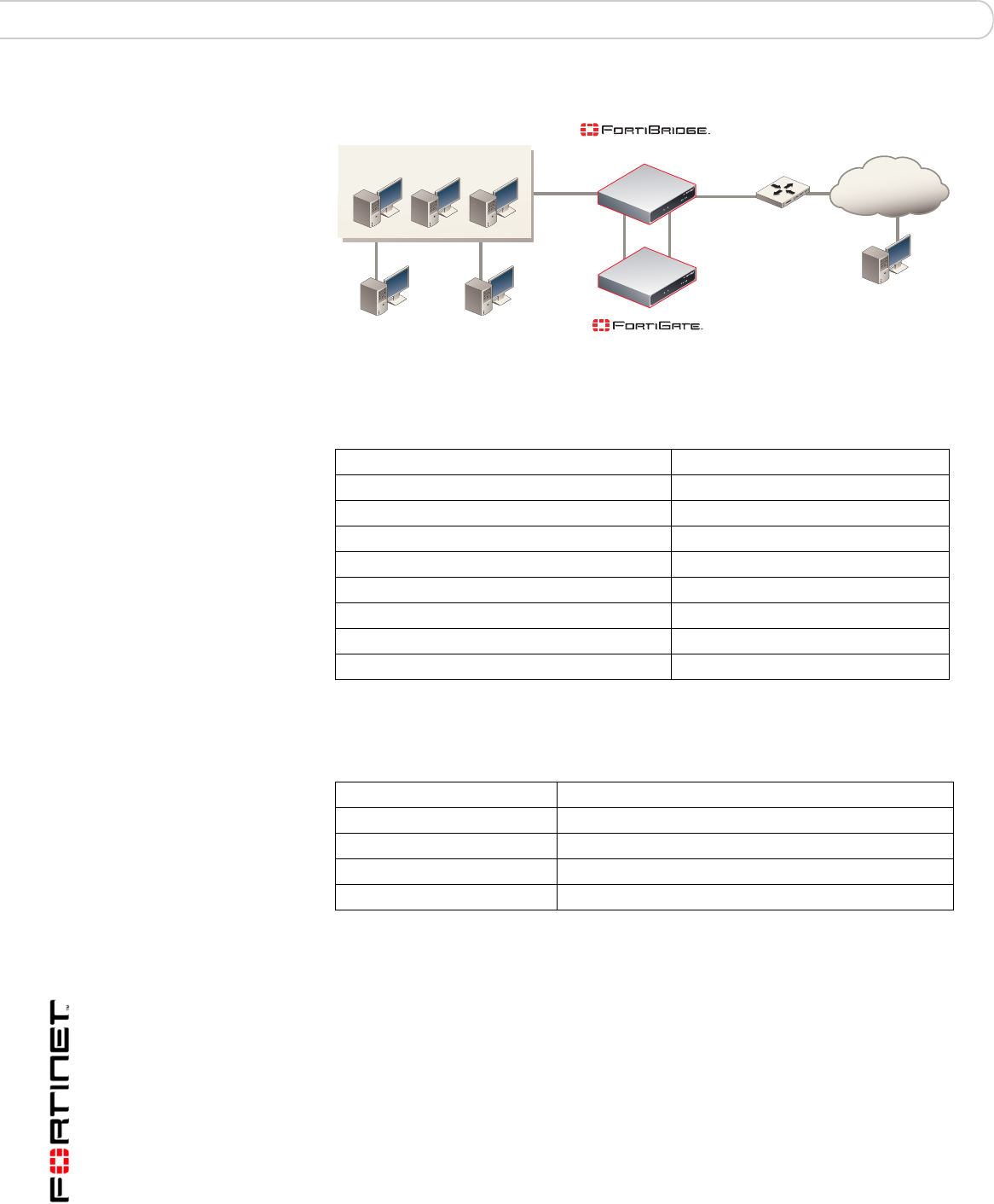
Figure 13: Example FortiBridge application
Table 9 lists the internal network configuration.
Table 10 lists the basic FortiBridge unit configuration settings.
Configuring FortiBridge probes
To monitor a FortiGate unit for failure, you configure the FortiBridge unit to send
probe packets through the FortiGate unit. Using probe packets, the FortiBridge
unit can confirm that the FortiGate unit can process ICMP (ping), HTTP, FTP,
POP3, SMTP, and IMAP traffic. Until you configure probes, the FortiBridge unit
cannot detect if the FortiGate unit has failed.
Table 9: Internal network configuration
FortiGate management IP address 172.20.120.10/24
Internal network subnet IP address 172.20.120.0/24
Router internal IP address 172.20.120.1/24
Internal network default route 172.20.120.1
Primary DNS server 172.20.120.2
Secondary DNS server 172.20.120.3
Syslog Server IP address 172.20.120.11
SNMP Manager IP address 172.20.120.12
Mail Server Name mail.myorg.com
Table 10: Basic FortiBridge unit configurations settings
Administrator password passWORD
Management IP address 172.20.120.20/24
Default route 172.20.120.1
Primary DNS server 172.20.120.2
Secondary DNS server 172.20.120.3
Router
INT 1
INT 2
EXT 1
EXT 2
Internal External
Internal network
Syslog server SNMP Manager
Mail server
Internet
(Transparent mode)
(Normal mode)

Configuration and operating procedures Configuring FortiBridge probes
FortiBridge Version 3.0 Administration Guide
09-30000-0163-20061109 37
This section describes:
•Probe settings
•Enabling probes
•Verifying that probes are functioning
•Tuning the failure threshold and probe interval
Probe settings
Configure probe settings to control the response when a FortiBridge probe
detects that the FortiGate unit has failed. Probe settings consist of:
To configure probe settings
This procedure shows how to configure the following probe settings:
• The FortiBridge unit responds to a FortiGate unit failure by failing open and by
sending an alert email, a syslog message, and an SNMP trap
• The dynamic IP pattern is 2.2.2.*
• The FortiGate unit serial number is FGT8002803923050
1Log in to the FortiBridge CLI.
Table 11: Probe settings
Probe Setting Description Default
Action on failure Set the FortiBridge unit response when a probe detects that
the FortiGate unit has failed. The FortiBridge unit can.
•Send alertmail
•Fail open
•Send an SNMP trap
•Send a message to a syslog server
You can add up to four actions on failure. All of the
configured actions on failure occur when the FortiBridge
unit detects a failure.
fail open
Dynamic IP
pattern Configure the INT 2 and EXT 2 interfaces with dynamic
probe IP addresses. The dynamic probe IP addresses
should not conflict with IP addresses on the network that
the FortiGate unit is connected to. These IP addresses are
not visible from the outside network, but they should not
conflict with IP addresses in packets passing through the
FortiBridge unit. You cannot change the dynamic IP pattern
if any probes are enabled.
(none)
FortiGate unit
serial number The serial number of the FortiGate unit that the FortiBridge
unit is connected to. The serial number appears in
FortiBridge alert mail, and syslog messages to identify the
FortiGate unit.
(none)
Note: The FortiBridge unit does not have to fail open if the FortiGate unit fails. The
FortiBridge unit can be configured just to send alerts if the FortiGate unit fails.
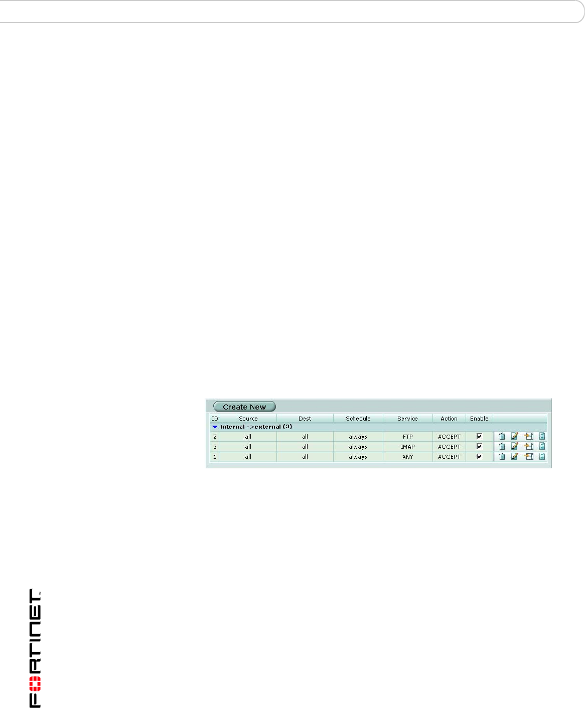
FortiBridge Version 3.0 Administration Guide
38 09-30000-0163-20061109
Configuring FortiBridge probes Configuration and operating procedures
2Configure probe settings. Enter:
config probe setting
set action_on_failure alertmail failopen snmp syslog
set dynamic_ip_pattern 2.2.2.*
set fgt_serial FGT8002803923050
end
Enabling probes
Enable probes to control the protocols that the FortiBridge unit uses to confirm
that the FortiGate unit is functioning normally. You can configure probes for ping
(ICMP), HTTP, FTP, POP3, SMTP, and IMAP protocols. For all probes you can
configure the probe interval (the time between consecutive probe packets), and
the probe threshold (the number of probe packets lost before the FortiBridge unit
registers a failure). For HTTP, FTP, POP3, SMTP, and IMAP probes you can also
change the probe port. You would change the probe port for a protocol if the
FortiGate unit uses a non-standard port for that protocol.
The FortiBridge unit simultaneously tests connectivity through the FortiGate unit
for each probe that you have enabled. The first probe that registers a failure
causes all probes to stop and the configured action on failure to occur.
Before you configure probes, the FortiGate unit must be configured to pass the
probe traffic. A single Internal->External firewall policy that allows all traffic also
allows all probe packets. You can also configure individual policies for each
protocol. For example, you could add the policies shown in Figure 14 to the
FortiGate unit.
Figure 14: Sample firewall policies
Policy 1 processes any network traffic. Policy 2 processes all FTP traffic. Policy 2
is above Policy 1 in the policy list, so FTP traffic is matched by policy 2. In the
same way, Policy 3 processes all IMAP traffic.
FTP and IMAP probes would be processed by policies 2 and 3 respectively. All
other probes would be processed by policy 1. This would include pings, SMTP
traffic and so on.
To enable and configure FortiBridge probes
The following steps show examples for configuring ping, HTTP, FTP, POP3,
SMTP, and IMAP probes. For a complete description of FortiBridge probes see
“probe probe_list {ping | http | ftp | pop3 | smtp | imap}” on page 55.
1Log into the FortiBridge CLI.
2Enable the ping probe using the default ping probe parameters. Enter:
config probe probe_list ping
set status enable
end

Configuration and operating procedures Configuring FortiBridge probes
FortiBridge Version 3.0 Administration Guide
09-30000-0163-20061109 39
3Display ping probe settings, enter:
get probe probe_list ping
name : ping
failure_threshold : 3
probe_interval : 1
status : enable
4Enable the FTP probe. Increase the failure threshold to 5 and the probe interval
to 8.
config probe probe_list ftp
set status enable
set failure_threshold 8
set probe_interval 5
end
The FortiBridge unit sends an FTP probe every 5 seconds and fails open if 8
consecutive FTP probe packets are not received.
5Display FTP probe settings. Enter:
get probe probe_list ftp
name : ftp
failure_threshold : 8
probe_interval : 5
status : enable
test_port : 21
6Enable the IMAP probe. Enter:
config probe probe_list IMAP
set status enable
end
7Enable the SMTP probe and change the port used by the probe from 25 to 26.
Enter:
config probe probe_list SMTP
set status enable
set test_port 26
end
Verifying that probes are functioning
You verify that the probes are functioning by viewing the sessions being
processed by the FortiGate unit.
To verify that probes are functioning
1Log into the FortiGate unit web-based manager.
2Go to System > Status > Session.
3View the sessions on the Session list.
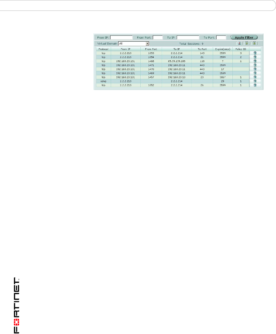
FortiBridge Version 3.0 Administration Guide
40 09-30000-0163-20061109
Configuring FortiBridge alerts Configuration and operating procedures
Figure 15: FortiGate Session list showing FortiBridge probes
This session list shows the following:
• The FortiBridge dynamic probe IP addresses are 2.2.2.213 and 2.2.2.214.
• IMAP probe packets (port 143) are processed by firewall policy 3.
• FTP probe packets (port 21) are processed by firewall policy 2.
• ping probe packets are processed by firewall policy 1.
• SMTP packets using port 26 are processed by firewall policy 1.
Tuning the failure threshold and probe interval
If you find the FortiBridge unit failing open when the FortiGate unit has not failed
or if the FortiGate unit fails and there is an unacceptably long delay before the
FortiBridge unit fails open, you should adjust the failure threshold and probe
interval.
Failing open when the FortiGate unit has not failed indicates that you should
increase the time the FortiBridge unit waits to fail open. During startup, if the
FortiBridge unit begins sending probe packets before the FortiGate unit has
completed its start up sequence the FortiBridge unit may detect a failure and
switch to bypass mode. Also, if the FortiGate unit is processing high traffic
volumes, a fail open could occur if the FortiGate unit delays FortiBridge probe
packets. You can increase the fail open delay by increasing the failure threshold
and probe interval.
An unacceptable delay before failing open means network traffic can be
interrupted for the time period between when the FortiGate unit fails and the
FortiBridge unit fails open. You can minimize the delay by reducing the failure
threshold and probe interval.
Configuring FortiBridge alerts
Configure FortiBridge alerts so that the alertemail, syslog, and snmp actions
on failure cause the FortiBridge unit to notify system administrators that the
FortiGate unit has failed. Until you configure alert email, syslog, and SNMP alerts,
the FortiBridge cannot notify system administrators of a FortiGate failure.
You can configure the following FortiBridge alerts:
•FortiBridge alert email
•FortiBridge syslog
•FortiBridge SNMP

Configuration and operating procedures Configuring FortiBridge alerts
FortiBridge Version 3.0 Administration Guide
09-30000-0163-20061109 41
FortiBridge alert email
If you set the probe action on failure to alertmail, you can configure alert email
so that the FortiBridge unit sends an email message to up to three email
addresses if the FortiBridge unit detects a failure. The alert email informs the
recipient that a FortiGate unit has failed, includes the protocol for which the failure
was detected, and includes the serial number of the FortiGate unit that failed.
Only the first probe to detect a failure triggers the actions on failure. So, even if
multiple probes are configured, when a failure is detected, the FortiBridge unit
sends one alert email.
Figure 16: Sample FortiBridge alert email message
FortiBridge detect FortiGate failure
Time: Tue Feb 1 19:58:46 2005
failed protocol: http
failed FortiGate serial number: FGT8002803923050
To configure alert email
Configuring FortiBridge alert email is similar to configuring FortiGate alert email.
1Log into the CLI.
2Configure alert email. Enter:
config alertemail setting
set server mail.myorg.com
set username user@company.com
set password PassWORD
set mailto1 user@company.com
set mailto1 user2@company.co.uk
set mailto1 user3@company.com
end
FortiBridge syslog
If you set the probe action on failure to syslog, you can configure FortiBridge
syslog so that the FortiBridge unit sends a syslog message to one syslog server if
the FortiBridge unit detects a failure. The message informs the recipient that a
FortiGate unit has failed, includes the protocol for which the failure was detected,
and includes the serial number of the FortiGate unit that failed.
Only the first probe to detect a failure triggers the actions on failure. So, even if
multiple probes are configured, when a failure is detected, the FortiBridge unit
sends one message.
Figure 17: Sample FortiBridge syslog messages
02-01-2005 18:22:50 Local7.Alert 172.20.120.13 date=2005-02-
01 time=15:28:22 device_id= log_id=0100020001 type=event
subtype=system pri=alert msg="FortiBridge detect FortiGate
failure: [failed time: Tue Feb 1 15:28:22 2005][failed
protocol: http] [failed FortiGate serial number:
FGT8002803923050]"

FortiBridge Version 3.0 Administration Guide
42 09-30000-0163-20061109
Configuring FortiBridge alerts Configuration and operating procedures
02-01-2005 8:21:27 Local7.Alert 172.20.120.13 date=2005-02-
01 time=15:26:59 device_id= log_id=0100020001 type=event
subtype=system pri=alert msg="FortiBridge detect FortiGate
failure: [failed time: Tue Feb 1 15:26:59 2005][failed
protocol: ftp] [failed FortiGate serial number:
FGT8002803923050]"
02-01-2005 18:17:17 Local7.Alert 172.20.120.13 date=2005-02-
01 time=15:22:49 device_id= log_id=0100020001 type=event
subtype=system pri=alert msg="FortiBridge detect FortiGate
failure: [failed time: Tue Feb 1 15:22:49 2005][failed
protocol: ping] [failed FortiGate serial number:
FGT8002803923050]"
02-01-2005 8:13:43 Local7.Alert 172.20.120.13 date=2005-02-
01 time=15:19:15 device_id= log_id=0100020001 type=event
subtype=system pri=alert msg="FortiBridge detect FortiGate
failure: [failed time: Tue Feb 1 15:19:15 2005][failed
protocol: smtp] [failed FortiGate serial number:
FGT8002803923050]"
To configure FortiBridge syslog
In most cases you should only need to configure the IP address of the syslog
server to receive FortiBridge syslog messages. See “log syslogd setting” on
page 54 for more FortiBridge syslog options.
1Log into the CLI.
2Configure syslog settings. Enter:
config log syslogd setting
set server 172.20.120.11
end
FortiBridge SNMP
If you set the probe action on failure to snmp, you can configure FortiBridge SNMP
settings so that the FortiBridge unit sends SNMP v1 and v2c compliant traps to
SNMP v1 and v2c compliant SNMP managers if the FortiBridge unit detects a
failure. The traps inform the recipient that a FortiGate unit has failed and include
the protocol for which the failure was detected.
Only the first probe to detect a failure triggers the actions on failure. So, even if
multiple probes are configured, when a failure is detected, the FortiBridge unit
sends one v1 SNMP trap and one v2c SNMP trap.
Configure FortiBridge SNMP by adding and configuring an SNMP community. An
SNMP community is a grouping of equipment for network administration
purposes. You can add up to three SNMP communities. Each community can
have a different configuration for SNMP traps. You can add the IP addresses of up
to 8 SNMP managers to each community.

Configuration and operating procedures Recovering from a FortiGate failure
FortiBridge Version 3.0 Administration Guide
09-30000-0163-20061109 43
To add and enable an SNMP community
1Log into the CLI.
2Add the first SNMP community and name it snmp1. Enter:
config system snmp community
edit 1
set name snmp_1
end
The new SNMP community is enabled by default. SNMP v1 and v2 traps are also
enable by default. You can disable traps and change ports. See “system snmp
community” on page 71 for more information.
3Add the IP addresses of two SNMP managers that can receive traps. Enter
config system snmp community
edit 1
config hosts
edit 1
set ip 172.20.120.12
next
edit 2
set ip 192.168.20.102
end
end
Recovering from a FortiGate failure
After the FortiBridge probe detects a FortiGate failure the FortiBridge unit stops
sending probes. To restart probes you can restart the FortiBridge unit, connect to
the FortiBridge CLI and enter the execute switch-mode command, or press
the mode button on the FortiBridge unit front panel.
Normally, an action on failure causes the FortiBridge unit to fail open. When the
FortiBridge unit fails open, it begins operating in Bypass mode. In bypass mode
the INT 1 and EXT 1 interfaces are directly connected and you cannot use Telnet
or SSH to connect to the FortiBridge CLI. Use the following procedure to recover
from bypass mode after a FortiGate failure and resume normal operation.
To resume normal operation from bypass mode
When the FortiBridge unit is operating in bypass mode, you need to do the
following to resume normal operation:
1Review FortiBridge alerts and check the status of your FortiGate unit and network
components to determine the source of the failure.
A network component or the FortiGate unit could have experienced a general
hardware failure or a specific software failure.

FortiBridge Version 3.0 Administration Guide
44 09-30000-0163-20061109
Manually switching between FortiBridge operating modes Configuration and operating procedures
2Make the required changes to fix the problem.
Depending on the cause, this could mean re-connecting and restarting the
FortiGate unit, or diagnosing a problem with the FortiGate unit or other network
component.
If all network and FortiGate unit hardware and software is functioning normally,
you may have to adjust FortiBridge probe settings. See “Tuning the failure
threshold and probe interval” on page 40.
3Manually switch the FortiBridge unit from bypass to normal mode.
Connect to the FortiBridge CLI using the console connection and enter the
command:
execute switch-mode
Or press the Mode button on the FortiBridge unit front panel.
Or restart the FortiBridge unit by cycling the power or from the console using he
execute reboot command. The FortiBridge unit always restarts on normal
mode.
Manually switching between FortiBridge operating modes
You can manually switch between FortiBridge operating modes from the
FortiBridge CLI or by pressing the Mode button on the FortiBridge front panel. To
switch operating modes from the CLI enter:
execute switch-mode
Backing up and restoring the FortiBridge configuration
Use the following procedures to backup and restore your FortiBridge
configuration. For both of these procedures, you must have a TFTP server that
you can connect to from any FortiBridge unit interface. The FortiBridge unit must
be operating in normal mode.
To back up the FortiBridge configuration
1Make sure that the TFTP server is running.
2Log into the FortiBridge CLI.
3Backup the system configuration to a text file on the TFTP server. Enter:
execute backup config <filename_str> <tftp-server_ipv4>
The config file is copied to the TFTP server and saved with the specified file
name.
To restore the FortiBridge configuration
1Make sure that the TFTP server is running.
2Log into the FortiBridge CLI.

Configuration and operating procedures Backing up and restoring the FortiBridge configuration
FortiBridge Version 3.0 Administration Guide
09-30000-0163-20061109 45
3Restore the system configuration from a text file on the TFTP server. Enter:
execute restore config <filename_str> <tftp-server_ipv4>
The config file is copied from the TFTP server to the FortiBridge unit. The
FortiBridge unit reboots loading the new configuration. While the FortiBridge unit
is rebooting, all network traffic passes directly from INT 1 and EXT 1 bypassing
the FortiGate unit.

FortiBridge Version 3.0 Administration Guide
46 09-30000-0163-20061109
Backing up and restoring the FortiBridge configuration Configuration and operating procedures

Using the CLI CLI basics
FortiBridge Version 3.0 Administration Guide
09-30000-0163-20061109 47
Using the CLI
This chapter explains how to connect to the command line interface (CLI) and
contains some basic information about using the CLI. You use CLI commands to
view all system information and to change all system configuration settings.
This chapter describes:
•CLI basics
•Connecting to the FortiBridge CLI using SSH or Telnet
CLI basics
The FortiBridge CLI functions the same as the FortiOS v2.80 CLI. For information
about the CLI structure, how to get command help, how to use command
completion, and other CLI features, see the FortiOS v2.80 FortiGate CLI
Reference Guide.
Connecting to the FortiBridge CLI using SSH or Telnet
You can use a direct console connection, SSH, or Telnet to connect to the
FortiBridge CLI.
•Setting administrative access for SSH or Telnet
•Connecting to the FortiBridge CLI using SSH
To connect to the FortiBridge CLI using Telnet, see “Connecting to the FortiBridge
CLI using Telnet” on page 26.
Setting administrative access for SSH or Telnet
To configure the FortiBridge unit to accept SSH or Telnet connections, you must
set administrative access to SSH or Telnet for the FortiBridge interface to which
your management computer connects.
To use the CLI to configure SSH or Telnet access
1Log into the CLI.
2Use the following command to configure an interface to accept SSH connections:
config system interface
edit <name_str>
set allowaccess ssh
end
Where <name_str> is the name of the FortiBridge interface to be configured to
accept SSH connections. Internal means the FortiBridge INT 1 interface. External
means the FortiBridge EXT 1 interface.

FortiBridge Version 3.0 Administration Guide
48 09-30000-0163-20061109
Connecting to the FortiBridge CLI using SSH or Telnet Using the CLI
For example, to configure the internal interface to accept SSH connections, enter:
config system interface
edit internal
set allowaccess ssh
end
3Use the following command to configure an interface to accept Telnet
connections:
config system interface
edit <name_str>
set allowaccess telnet
end
Where <name_str> is the name of the FortiBridge interface to be configured to
accept Telnet connections.
For example, to configure the internal interface to accept Telnet connections,
enter:
config system interface
edit internal
set allowaccess telnet
end
4To confirm that you have configured SSH or Telnet access correctly, enter the
following command to view the access settings for the interface:
get system interface <name_str>
The CLI displays the settings, including the management access settings, for the
named interface.
Other access methods
The procedure above shows how to allow access only for Telnet or only for SSH.
If you want to allow both or any of the other management access types you must
include all the options you want to apply. For example to allow ping, Telnet and
SSH access to an interface, the set portion of the command is
set allowaccess ping telnet ssh.
Connecting to the FortiBridge CLI using SSH
Secure Shell (SSH) provides strong secure authentication and secure
communications to the FortiBridge CLI from your internal network or the internet.
Once the FortiBridge unit is configured to accept SSH connections, you can run
an SSH client on your management computer and use this client to connect to the
FortiBridge CLI.
Note: Remember to press Enter at the end of each line in the command example. Also,
type end and press Enter to commit the changes to the FortiBridge configuration.
Note: A maximum of 5 SSH connections can be open at the same time.

Using the CLI Connecting to the FortiBridge CLI using SSH or Telnet
FortiBridge Version 3.0 Administration Guide
09-30000-0163-20061109 49
To connect to the CLI using SSH
1Install and start an SSH client.
2Connect to a FortiBridge interface that is configured for SSH connections.
3Type a valid administrator name and press Enter.
4Type the password for this administrator and press Enter.
The FortiBridge model name followed by a # is displayed.
You have connected to the FortiBridge CLI, and you can enter CLI commands.

FortiBridge Version 3.0 Administration Guide
50 09-30000-0163-20061109
Connecting to the FortiBridge CLI using SSH or Telnet Using the CLI

config CLI commands
FortiBridge Version 3.0 Administration Guide
09-30000-0163-20061109 51
config CLI commands
alertemail setting
log syslogd setting
probe probe_list {ping | http | ftp |
pop3 | smtp | imap}
probe setting
system accprofile
system admin
system console
system dns
get system status
system fail_close
system global
system interface {internal |
external}
system manageip
system route
system snmp community

FortiBridge Version 3.0 Administration Guide
52 09-30000-0163-20061109
alertemail setting config CLI commands
alertemail setting
Use this command to configure the FortiBridge unit to send alert email to up to three recipients when
action on failure is set to send a alert email message.
Command syntax pattern
config alertemail setting
set <keyword> <variable>
end
config alertemail setting
unset <keyword>
get alertemail setting
show alertemail setting
Examples
This example shows how to configure the SMTP server and user name and password, enable
authentication and add two email addresses.
config alertemail setting
set server mail.ourcompany.com
set username fortigate@ourcompany.com
set authenticate enable
set password pwd23
set mailto1 admin1@ourcompany.com
set mailto2 admin2@ourcompany.com
end
This example shows how to display the alertemail settings.
get alertemail setting
This example shows how to display the configuration of the alertemail setting command.
show alertemail setting
Keywords and variables Description Default
authenticate
{disable | enable}
Enable SMTP authentication if the FortiBridge unit is required to
authenticate to connect to the SMTP server. disable
mailto1
<email-address_str>
Enter an email address. This is one of the email addresses to which
the FortiBridge unit sends alert email. No
default.
mailto2
<email-address_str>
Enter an email address. This is one of the email addresses to which
the FortiBridge unit sends alert email. No
default.
mailto3
<email-address_str>
Enter an email address. This is one of the email addresses to which
the FortiBridge unit sends alert email. No
default.
password
<password_str>
Enter the password that the FortiBridge unit needs to access the
SMTP server. No
default.
server
{<name_str> |
<address_ipv4>}
Enter the name of the SMTP server, in the format
smtp.domain.com, to which the FortiBridge unit should send
email. The SMTP server can be located on any network connected
to the FortiBridge unit.
No
default.
username
<user-name_str>
Enter a valid email address in the format user@domain.com. This
address appears in the From header of the alert email. No
default.


FortiBridge Version 3.0 Administration Guide
54 09-30000-0163-20061109
log syslogd setting config CLI commands
log syslogd setting
Use this command to configure the FortiBridge unit to send a syslog message to a remote syslog
server when action on failure is set to send a syslog message.
Command syntax pattern
config log syslogd setting
set <keyword> <variable>
end
config log syslogd setting
unset <keyword>
get log syslogd setting
show log syslogd setting
Example
This example shows how to enable logging to a remote syslog server, configure an IP address and
port for the server, and enable logging in CSV format.
config log syslogd setting
set status enable
set server 220.210.200.190
set port 601
set csv enable
end
This example shows how to display the log setting for logging to a remote syslog server.
get log syslogd setting
This example shows how to display the configuration for logging to a remote syslog server.
show log syslogd setting
If the show command returns you to the prompt, the settings are at default.
Related Commands
•probe setting
Keywords and variables Description Default
csv {disable | enable} Enable formatting log messages in Comma Separated Value
(CSV) format. If you do not enable CSV format the FortiBridge
unit produces plain text log messages.
disable
facility {alert | audit |
auth | authpriv | clock |
cron | daemon | ftp |
kernel | local0 | local1
| local2 | local3 |
local4 | local5 | local6
| local7 | lpr | mail |
news | ntp | syslog |
user | uucp}
Enter the facility type, which identifies the source of the log
message to the syslog server. You might want to change facility
to distinguish log messages from different FortiBridge units.
local7
port <port_integer> Enter the port number for communication with the syslog server. 514
server <address_ipv4> Enter the IP address of the syslog server that stores the logs. No default.
status {disable | enable} Enter enable to enable logging to a remote syslog server. disable

config CLI commands probe probe_list {ping | http | ftp | pop3 | smtp | imap}
FortiBridge Version 3.0 Administration Guide
09-30000-0163-20061109 55
probe probe_list {ping | http | ftp | pop3 | smtp | imap}
Use this command to configure probes for ping, HTTP, FTP, POP3, SMTP, and IMAP traffic. Probes
monitor different types of traffic. For each protocol you configure the time interval between probes
(interval) and how many lost probes are required to register a failure (threshold). You can also enable
each probe and in all cases except ping you can specify the port used by the probe.
Command syntax pattern
config probe probe_list {ping | http | ftp | pop3 | smtp | imap}
set <keyword>
end
config probe probe_list {ping | http | ftp | pop3 | smtp | imap}
unset <keyword>
end
get probe probe_list {ping | http | ftp | pop3 | smtp | imap}
show probe probe_list {ping | http | ftp | pop3 | smtp | imap}
Example
Use the following command to enable HTTP probes and change the HTTP failure threshold to 5 and
the probe interval to 3.
config probe probe_list http
set status enable
set failure_threshold 5
set probe_interval 3
end
This example shows how to display the settings for the probe probe_list command.
get probe probe_list
This example shows how to display the settings for the http probe.
get probe probe_list http
This example shows how to display the configuration for the probe probe_list command.
show probe probe_list
Related Commands
•probe setting
Keywords and variables Description Default
failure_threshold
<threshold_integer>
The number of probe packets that are lost before the
FortiBridge unit determines that the FortiGate unit has failed. 3
probe_interval
<probe_integer>
The number of seconds between probe packets. 1
status {disable | enable} Enable or disable sending probe packets for the current
probe protocol disable
test_port
<port-number_integer>
The port number on which the probe sends packets for a
give protocol. ping (none)
http 80
ftp 21
pop3 110
smtp 25
imap 143

FortiBridge Version 3.0 Administration Guide
56 09-30000-0163-20061109
probe setting config CLI commands
probe setting
Use this command to configure how the FortiBridge unit responds when a probe determines that the
FortiGate unit has failed. You can also configure the dynamic IP pattern used by probes and add the
FortiGate serial number, which is used in FortiBridge alert messages.
Command syntax pattern
config probe setting
set <keyword>
end
config probe setting
unset <keyword>
end
get probe setting
show probe setting
Example
Use the following command to configure the FortiBridge unit to send alert email and fail open when a
probe detects a failure, set the IP pattern to 2.2.2.* and add the FGT8002803923050 FortiGate serial
number
config probe setting
set action_on_failure alertmail failopen
set dynamic_ip_pattern 2.2.2.*
set fgt_serial FGT8002803923050
end
Related Commands
•probe probe_list {ping | http | ftp | pop3 | smtp | imap}
Keywords and variables Description Default
action_on_failure
{alertmail failopen snmp
syslog}
Set how the FortiBridge unit responds when a probe detects that
the FortiGate unit has failed. You can enter one or more of the
action types separated by spaces. Enter all of the action options
required. If you want to remove an option from the list or add an
option to the list, you must retype the list with the option removed
or added.
failopen
dynamic_ip_pattern
<address_ipv4>.*
Configure the INT 2 and EXT 2 interfaces with dynamic probe IP
addresses. The dynamic probe IP addresses should not conflict
with IP addresses on the network that the FortiGate unit is
connected to. These IP addresses are not visible from the
outside network, but they should not conflict with IP addresses in
packets passing through the FortiBridge unit. You cannot change
the dynamic IP pattern if any probes are enabled.
none
fgt_serial
<serial_string>
The serial number of the FortiGate unit that the FortiBridge unit is
connected to. This number is used in FortiBridge alert messages
to identify the FortiGate unit.
none

config CLI commands system accprofile
FortiBridge Version 3.0 Administration Guide
09-30000-0163-20061109 57
system accprofile
Use this command to add access profiles that control administrator access to FortiBridge features.
Each administrator account must include an access profile. You can create access profiles that deny
access to or allow read only, write only, or both read and write access to FortiBridge features.
Command syntax pattern
config system accprofile
edit <profile-name_str>
set <keyword> <variable>
end
config system accprofile
edit <profile-name_str>
unset <keyword>
end
config system accprofile
delete <profile-name_str>
end
get system accprofile [<profile-name_str>]
show system accprofile [<profile-name_str>]
Keywords and variables Description Default
admingrp {none | r | rw | w} Control administrator access to FortiBridge administrator
accounts and access profiles.
none deny access.
r read only access.
rw read write access.
w write only access.
none
loggrp {none | r | rw | w} Control administrator access to log and alert email settings.
none deny access.
r read only access.
rw read write access.
w write only access.
none
sysgrp {none | r | rw | w} Control administrator access to system configuration settings.
none deny access.
r read only access.
rw read write access.
w write only access.
none
sysshutdowngrp {none | r |
rw | w}
Control administrator access to system shutdown, system,
reboot, and firmware upgrade functions.
none deny access.
r read only access.
rw read write access.
w write only access.
none

FortiBridge Version 3.0 Administration Guide
58 09-30000-0163-20061109
system accprofile config CLI commands
Example
Use the following commands to add a new access profile named policy_profile that allows read
and write access system shutdown. An administrator account with this access profile can shutdown the
system and upgrade firmware.
config system accprofile
edit policy_profile
set secgrp rw
end
This example shows how to display the settings for the system accprofile command.
get system accprofile
This example shows how to display the settings for the policy_profile access profile.
get system accprofile policy_profile
This example shows how to display the configuration for the system accprofile command.
show system accprofile
This example shows how to display the configuration for the policy_profile access profile.
get system accprofile policy_profile
Related Commands
•system admin

config CLI commands system admin
FortiBridge Version 3.0 Administration Guide
09-30000-0163-20061109 59
system admin
Use this command to add, edit, and delete administrator accounts.
Use the admin account or an account with system configuration read and write privileges to add new
administrator accounts and control their permission levels. Each administrator account must include
an access profile. You cannot delete the admin administrator account. You cannot change the admin
administrator account permissions.
Command syntax pattern
config system admin
edit <name_str>
set <keyword> <variable>
end
config system admin
edit <name_str>
unset <keyword>
end
config system admin
delete <name_str>
end
get system admin [<name_str>]
show system admin [<name_str>]
Keywords and variables Description Default
accprofile
<profile-name_str>
Enter the name of the access profile to assign to this administrator
account. Access profiles control administrator access to FortiBridge
features.
No
default.
password <password_str> Enter a password for the administrator account. For improved
security, the password should be at least 6 characters long. No
default.
trusthost1
<address_ipv4mask>
An IP address or subnet address and netmask from which the
administrator can connect to the FortiBridge unit.
If you want the administrator to be able to access the FortiBridge unit
from any address, set one of the trusted hosts to 0.0.0.0 and the
netmask to 0.0.0.0.
0.0.0.0/
0.0.0.0
trusthost2
<address_ipv4mask>
An IP address or subnet address and netmask from which the
administrator can connect to the FortiBridge unit.
If you want the administrator to be able to access the FortiBridge unit
from any address, set one of the trusted hosts to 0.0.0.0 and the
netmask to 0.0.0.0.
0.0.0.0/
0.0.0.0
trusthost3
<address_ipv4mask>
An IP address or subnet address and netmask from which the
administrator can connect to the FortiBridge unit.
If you want the administrator to be able to access the FortiBridge unit
from any address, set one of the trusted hosts to 0.0.0.0 and the
netmask to 0.0.0.0.
0.0.0.0/
0.0.0.0

FortiBridge Version 3.0 Administration Guide
60 09-30000-0163-20061109
system admin config CLI commands
Example
Use the following commands to add a new administrator account named new_admin with the
password set to p8ssw0rd and that includes an access profile named policy_profile.
Administrators that log in to this account will have administrator access to the FortiBridge unit from any
IP address.
config system admin
edit new_admin
set password p8ssw0rd
set accprofile policy_profile
end
This example shows how to display the settings for the system admin command.
get system admin
This example shows how to display the settings for the new_admin administrator account.
get system admin new_admin
This example shows how to display the configuration for the system admin command.
show system admin
Related Commands
•system accprofile

config CLI commands system console
FortiBridge Version 3.0 Administration Guide
09-30000-0163-20061109 61
system console
Use this command to set the console command mode and output setting.
Command syntax pattern
config system console
set <keyword> <variable>
end
config system console
unset <keyword>
end
get system console
show system console
Example
This example shows how to set the number of lines per page to 25.
config system console
set page 25
end
This example shows how to display the settings for the console command.
get system console
This example shows how to display the configuration for the console command.
show system console
Keywords and variables Description Default
mode {batch | line} Set the console mode to line or batch. Used for auto testing only. line
output {standard | more} Set console output to standard (no pause) or more (pause after
each screen, resume on keypress). standard

FortiBridge Version 3.0 Administration Guide
62 09-30000-0163-20061109
system dns config CLI commands
system dns
Use this command to set the DNS server addresses. Several FortiBridge functions, including sending
email alerts and URL blocking, use DNS.
On models numbered 100 and lower, you can use this command to set up DNS forwarding.
Command syntax pattern
config system dns
set <keyword> <variable>
end
config system dns
unset <keyword>
end
get system dns
show system dns
Example
This example shows how to set the primary FortiBridge DNS server IP address to 45.37.121.76 and
the secondary FortiBridge DNS server IP address to 45.37.121.77.
config system dns
set primary 45.37.121.76
set secondary 45.37.121.77
end
This example shows how to display the settings for the system dns command.
get system dns
This example shows how to display the configuration for the system dns command.
show system dns
Keywords and variables Description Default
primary <address_ipv4> Enter the primary DNS server IP address. 65.39.139.53
secondary <address_ipv4> Enter the secondary DNS IP server address. 65.39.139.63

config CLI commands get system status
FortiBridge Version 3.0 Administration Guide
09-30000-0163-20061109 63
get system status
Use this command to display system status information. This command displays:
• FortiBridge unit firmware version and build number
• FortiBridge unit host name
• FortiBridge unit operation mode (normal or bypass)
• FortiBridge unit serial number
Command syntax pattern
get system status

FortiBridge Version 3.0 Administration Guide
64 09-30000-0163-20061109
system fail_close config CLI commands
system fail_close
Use this command to configure the fail close feature.
Command syntax pattern
config system fail_close
set <keyword> <variable>
end
config system fail_close
unset <keyword>
end
get system fail_close
show system fail_close
Keywords and variables Description Default
status {disable |
fail_close |
fail_bypass}
The fail_bypass option is only available on the
FBG-1000F.
When the FortiBridge detects an upstream or downstream
network disconnection (whether due to a cut/disconnected
cable, failure of the connected device, or failure of the
FortiBridge unit’s own interface), it will bring down its own
network interface after waiting the amount of time set for
the threshold variable. If the fail close status is set to
fail_close and a switch connected to EXT1 fails, the
FortiBridge would bring down its own INT1. This way, the
device connected to INT1 will be able to determine there is
a problem Similarly, if a device connected to INT1 fails, the
FortiBridge would bring down its own EXT1.
When the problem is corrected, the FortiBridge will enable
its own network interface after waiting the amount of time
set for the threshold variable.
Some early FBG-1000 units will return an Not supported
by this hardware error when this command is invoked. This
is normal as hardware support for fail_close was only
added in later units.
When using a FBG-1000F, some fiber-connected
equipment doesn’t properly detect the status of a
FortiBridge interface brought down by the fail_close
option. To prevent this problem, use fail_bypass
instead. If a network problem is detected with
fail_bypass set, the FortiBridge will switch to bypass
mode. This way, the network devices can detect the
problem directly through the FortiBridge. Note that
fail_bypass causes the FortiBridge to remove itself
from the network when a problem is detected so manual
intervention is required to switch back to normal mode.
disable
threshold
<seconds_integer>
Enter how long, in seconds, the FortiBridge will wait after
detecting a network problem before activating the fail close
feature. Except when fail_bypass is set, the FortiBridge
will wait the specified time before deactivating the fail close
feature when the problem is corrected.
3

config CLI commands system fail_close
FortiBridge Version 3.0 Administration Guide
09-30000-0163-20061109 65
Example
This example shows how to enable the FortiBridge fail_close feature, and set the threshold time to five
seconds.
config system fail_close
set status fail_close
set threshold 5
end
This example shows how to display the configuration for the system fail_close command.
show system fail_close

FortiBridge Version 3.0 Administration Guide
66 09-30000-0163-20061109
system global config CLI commands
system global
Use this command to configure global settings that affect various FortiBridge systems and
configurations.
Command syntax pattern
config system global
set <keyword> <variable>
end
config system global
unset <keyword>
end
get system global
show system global
Keywords and variables Description Default
admintimeout
<minutes_integer>
Set the administrator idle timeout to control the
amount of inactive time before the administrator must
log in again. The maximum admintimeout is 480
minutes (8 hours). To improve security keep the idle
timeout at the default value.
5
dst {disable | enable} Enable or disable daylight saving time.
If you enable daylight saving time, the FortiBridge unit
adjusts the system time when the time zone changes
to daylight saving time and back to standard time.
disable
heartbeat {disable |
enable }
For future use. disable
hostname <name_str> Type a name for this FortiBridge unit. FortiBridge model
name.
interface-speed {100full
| 100half | 10full |
10half | auto }
This command is only available for the FBG-1000.
Set the network interface speed or allow each
interface to auto-sense the correct speed. Set to
auto, each FortiBridge network interface will
autosense the correct speed and adjust accordingly. If
the interface-speed command is used to specify a
speed, all FortiBridge interfaces are locked to the
selected speed.
Although the FortiBridge supports 10/100/1000mbps
speeds when set to auto, 1000half and 1000full are
not available for manual selection.
Some early units will return an Not supported by this
hardware error when this command is invoked. This is
normal as hardware support for interface-speed
was only added in later units.
auto
ntpserver {<name_str> |
<address_ipv4>}
Enter the domain name or IP address of a Network
Time Protocol (NTP) server. 132.246.168.148
ntpsync {disable |
enable}
Enable or disable automatically updating the system
date and time by connecting to a Network Time
Protocol (NTP) server. For more information about
NTP and to find the IP address of an NTP server that
you can use, see http://www.ntp.org.
disable

config CLI commands system global
FortiBridge Version 3.0 Administration Guide
09-30000-0163-20061109 67
Example
This example shows how to set the FortiBridge system timezone, add the IP address of an NTP
server, and enable synchronization with the NTP server. The IP address of the NTP server is
192.168.20.1.
config system global
set timezone 16
set ntpserver 192.168.20.1
set ntpsync enable
end
This example shows how to display the settings for the system global command.
get system global
This example shows how to display the configuration for the system global command.
show system global
syncinterval
<minutes_integer>
Enter how often, in minutes, the FortiGate unit should
synchronize its time with the Network Time Protocol
(NTP) server. The syncinterval number can be 1
to 1440; 0 disables time synchronization.
60
timezone
<timezone_integer>
The number corresponding to your time zone. Press ?
to list time zones and their numbers. Choose the time
zone for the FortiBridge unit from the list and enter the
correct number.
00
Keywords and variables Description Default

FortiBridge Version 3.0 Administration Guide
68 09-30000-0163-20061109
system interface {internal | external} config CLI commands
system interface {internal | external}
Use this command to configure management access to the FortiBridge internal or external interface.
The internal interface in the INT 1 interface. The external interface is the EXT 1 interface.
Command syntax pattern
Entering a name string for the edit keyword that is not the name of a physical interface adds a VLAN
subinterface.
config system interface {internal | external}
set <keyword> <variable>
end
config system interface {internal | external}
unset <keyword>
end
get system interface <name_str>
show system interface <name_str>
Example
This example shows how to set management access for the INT 1 interface to ping, and ssh.
config system interface internal
set allowaccess ping ssh
end
This example shows how to display the settings for the INT 1interface.
get system interface internal
This example shows how to display the configuration for the INT 1interface.
show system interface internal
Keywords and variables Description Default
allowaccess {ping ssh
telnet}
Allow management access to the interface. You can enter one or
more of the management access types separated by spaces.
Enter all the management access options for the interface. Use a
space to separate the options. If you want to remove an option
from the list or add an option to the list, you must retype the list
with the option removed or added.
INT 1
(internal)
ping,
ssh,
telnet
EXT 1
(external)
none

config CLI commands system manageip
FortiBridge Version 3.0 Administration Guide
09-30000-0163-20061109 69
system manageip
Configure the FortiBridge management IP address. Use the management IP address for management
access to the FortiBridge unit.
Command syntax pattern
config system manageip
set <keyword> <variable>
end
config system manageip
unset <keyword>
end
get system manageip
show system manageip
Example
This example shows how to set the management IP address to 192.168.2.80 and the netmask to
255.255.255.0.
config system manageip
set ip 192.168.2.80 255.255.255.0
end
This example shows how to display the settings for the manageip command.
get system manageip
This example shows how to display the configuration for the manageip command.
show system manageip
Related Commands
•system interface {internal | external}
Keywords and variables Description Default
ip <address_ipv4mask> Set the IP address and netmask of the FortiBridge
management interface. 192.168.1.99
255.255.255.0

FortiBridge Version 3.0 Administration Guide
70 09-30000-0163-20061109
system route config CLI commands
system route
Use this command to add or edit FortiBridge static routes.
Command syntax pattern
config system route
edit <sequence_integer>
set <keyword> <variable>
end
config router static
unset <keyword>
get system route
show system route
Example
This example shows how to edit a FortiBridge static route.
config system route
edit 2
set dst 192.168.22.0 255.255.255.0
set gateway 192.168.22.44
end
This example shows how to display the list of static route numbers.
get system route
This example shows how to display the settings for static route 2.
get system route 2
This example shows how to display the static route configuration.
show system route
This example shows how to display the configuration for static route 2.
show system route 2
Keywords and variables Description Default
distance
<distance_integer>
The administrative distance for the route. Using administrative
distance you can specify the relative priorities of different routes to the
same destination. A lower administrative distance indicates a more
preferred route. Distance can be an integer from 1-255.
10
dst <destination-
address_ipv4mask>
The destination IP address and netmask for this route.
Enter 0.0.0.0 0.0.0.0 for the destination IP address and netmask
to add a default route.
0.0.0.0
0.0.0.0
gateway <gateway-
address_ipv4>
The IP address of the first next hop router to which this route directs
traffic. No
default.

config CLI commands system snmp community
FortiBridge Version 3.0 Administration Guide
09-30000-0163-20061109 71
system snmp community
Use this command to configure SNMP communities. Add SNMP communities so that the FortiBridge
unit can send SNMP v1 and v2c traps to SNMP managers when action on failure is set to send SNMP
traps. You can add up to three SNMP communities. Each community can have a different configuration
for SNMP traps. You can also the add IP addresses of up to 8 SNMP managers to each community.
Command syntax pattern
config system snmp community
edit <id_integer>
set <keyword> <variable>
end
config system snmp community
edit <id_integer>
unset <keyword>
end
config system snmp community
delete <id_integer>
end
get system snmp community [<id_integer>]
show system snmp community [<id_integer>]
The config system snmp community command has one subcommand.
config hosts
config hosts
Access the hosts subcommand using the snmp community command. Use this command to add
SNMP manager IP addresses to an SNMP community.
Keywords and variables Description Default
name <name_str> The name of the SNMP community. No default.
status {disable | enable} Enable or disable the SNMP community. enable
trap_v1_lport
<local-port_integer>
SNMP v1 local port number used for sending traps to the
SNMP managers added to this SNMP community. 162
trap_v1_rport
<remote-port_integer>
SNMP v1 remote port number used for sending traps to the
SNMP managers added to this SNMP community. 162
trap_v1_status {disable
| enable}
Enable or disable SNMP v1 traps for this SNMP community. enable
trap_v2c_lport
<local-port_integer>
SNMP v2c local port number used for sending traps to the
SNMP managers added to this SNMP community. 162
trap_v2c_rport
<remote-port_integer>
SNMP v2c remote port number used for sending traps to the
SNMP managers added to this SNMP community. 162
trap_v2c_status {disable
| enable}
Enable or disable SNMP v2c traps for this SNMP community. enable

FortiBridge Version 3.0 Administration Guide
72 09-30000-0163-20061109
system snmp community config CLI commands
Command syntax pattern
config hosts
edit <id_integer>
set <keyword> <variable>
end
config hosts
edit <id_integer>
unset <keyword>
end
config hosts
delete <id_integer>
end
get system snmp community [<id_integer>]
show system snmp community [<id_integer>]
Example
This example shows how to add a new SNMP community named SNMP_Com1. The default
configuration can be used in most cases with only a few modifications. In the example below the
community is added, given a name, and then because this community is for an SNMP manager that is
SNMP v1 compatible, v2c functionality is disabled. After the community is configured the SNMP
manager is added. The SNMP manager IP address is 192.168.20.34.
config system snmp community
edit 1
set name SNMP_Com1
set trap_v2c_status disable
config hosts
edit 1
set ip 192.168.10.34
end
end
This example shows how to display the settings for the system snmp community command.
get system snmp community
This example shows how to display the settings for the SNMP community with ID 1.
get system snmp community 1
This example shows how to display the configuration for the snmp community command.
show system snmp community
This example shows how to display the configuration for the SNMP community with ID 1.
show system snmp community 1
Keywords and variables Description Default
ip <address_ipv4> The IP address of the SNMP manager. 0.0.0.0


FortiBridge Version 3.0 Administration Guide
74 09-30000-0163-20061109
backup execute CLI commands
backup
Backup the FortiBridge configuration to a file on a TFTP server.
Command syntax
execute backup config <filename_str> <tftp-server_ipv4>
Example
This example shows how to backup a system configuration file from the FortiBridge unit to a TFTP
server. The name to give the configuration file on the TFTP server is fbdg.cfg. The IP address of the
TFTP server is 192.168.1.23.
execute backup config fbdg.cfg 192.168.1.23
Keywords and variables Description
config Back up the FortiBridge configuration.
<filename_str> The name to give the file that is copied to the TFTP server.
<tftp-server_ipv4> The TFTP server IP address.

execute CLI commands date
FortiBridge Version 3.0 Administration Guide
09-30000-0163-20061109 75
date
Get or set the system date.
Command syntax
execute date [<date_str>]
date_str has the form mm/dd/yyyy, where
•mm is the month and can be 01 to 12
•dd is the day of the month and can be 01 to 31
•yyyy is the year and can be 2001 to 2100
If you do not specify a date, the command returns the current system date.
Example
This example sets the date to 17 September 2004:
execute date 09/17/2004

FortiBridge Version 3.0 Administration Guide
76 09-30000-0163-20061109
factoryreset execute CLI commands
factoryreset
Reset the FortiBridge configuration to factory default settings.
Command syntax
execute factoryreset
!Caution: This procedure deletes all changes that you have made to the FortiBridge configuration and reverts the
system to its original configuration, including resetting the management IP address.

execute CLI commands ping
FortiBridge Version 3.0 Administration Guide
09-30000-0163-20061109 77
ping
Send five ICMP echo requests (pings) to test the network connection between the FortiBridge unit and
another network device.
Command syntax
execute ping {<address_ipv4> | <host-name_str>}
Example
This example shows how to ping a host with the IP address 192.168.1.23.
execute ping 192.168.1.23

FortiBridge Version 3.0 Administration Guide
78 09-30000-0163-20061109
reboot execute CLI commands
reboot
Restart the FortiBridge unit.
Command syntax
execute reboot

execute CLI commands restore
FortiBridge Version 3.0 Administration Guide
09-30000-0163-20061109 79
restore
Use this command to restore a backup configuration and to change the FortiBridge firmware.
Command syntax
execute restore config <filename_str> <tftp-server_ipv4>
execute restore image <filename_str> <tftp-server_ipv4>
Example
This example shows how to upload a configuration file from a TFTP server to the FortiBridge unit and
restart the FortiBridge unit with this configuration. The name of the configuration file on the TFTP
server is backupconfig. The IP address of the TFTP server is 192.168.1.23.
execute restore config backupconfig 192.168.1.23
Keywords and variables Description
config Restore a system configuration. The new configuration replaces the existing
configuration, including administrator accounts and passwords.
image Upload a firmware image from a TFTP server to the FortiBridge unit. The
FortiBridge unit reboots, loading the new firmware.
<filename_str> The name of file that is uploaded from the TFTP server.
<tftp-server_ipv4> The TFTP server IP address.

FortiBridge Version 3.0 Administration Guide
80 09-30000-0163-20061109
switch-mode execute CLI commands
switch-mode
Use this command to switch between bypass and normal mode.
Command syntax
execute switch-mode

execute CLI commands time
FortiBridge Version 3.0 Administration Guide
09-30000-0163-20061109 81
time
Get or set the system time.
Command syntax
execute time [<time_str>]
time_str has the form hh:mm:ss, where
•hh is the hour and can be 00 to 23
•mm is the minutes and can be 00 to 59
•ss is the seconds and can be 00 to 59
If you do not specify a time, the command returns the current system time.
Example
This example sets the system time to 15:31:03:
execute time 15:31:03

FortiBridge Version 3.0 Administration Guide
82 09-30000-0163-20061109
time execute CLI commands

Index
FortiBridge Version 3.0 Administration Guide
09-30000-0163-20061109 83
Index
A
accprofile 59
action on failure
fail open 37
probe 37
send alertmail 37
SNMP trap 37
syslog 37
action_on_failure 56
admingrp 57
administrative access
for SSH or Telnet 47
administrator
adding a password 27
administrator accounts
adding 29
admintimeout 66
alert email
configuring 41
sample message 41
alertemail setting 52
alertmail
action on failure 37
action_on_failure 56
alerts
configuring 40
allowaccess {http https ping snmp ssh telnet} 68
authenticate {disable | enable} 52
B
backing up
configuration 44
backup 74
basic configuration 26
basic information
FortiBridge 19
basic settings 36
bypass mode 14
connecting to the CLI 14
resuming normal mode 43
switching to normal mode 14
C
CLIbasics 47
config commands 51
connecting to 25
connecting to in bypass mode 14
connecting to the console 25
connecting using SSH or Telnet 47
connecting using Telnet 26
resetting to factory defaults 30
using 47
cluster
FortiBridge application 15
command line interface
connecting to 25
community
adding an SNMP 43
SNMP 42
config 74, 79
CLI commands 51
config hosts 71
configuration
backing up and restoring 44
basic FortiBridge 26
factory default 22
procedures 35
configuration example
HA cluster 15
other FortiGate interfaces 16
standalone FortiGate unit 9
connect
FortiBridge unit 10
to the CLI 25
connecting
FortiBridge unit 23
connectors
FortiBridge-1000 22
FortiBridge-1000F 22
console
connecting to 25
csv {disable | enable} 54
customer service 8
D
date 75
changing 29
default
probe settings 37
resetting to factory defaults 30
default configuration 22
distance 70
DNS server
changing IP addresses 28
dst 70
dst {disable | enable} 66
dynamic IP pattern
probe setting 37
dynamic_ip_pattern 56
E
email
alert 41
example configuration 9

FortiBridge Version 3.0 Administration Guide
84 09-30000-0163-20061109
Index
HA cluster 15
other FortiGate interfaces 16
execute
CLI commands 73
switch-mode 44
execute switch-mode 14
EXT 1
management access 29
F
facility 54
factory default
configuration 22
resetting 30
factoryreset 76
fail bypass 64
fail close 64
fail bypass 64
threshold 64
fail open 37
action_on_failure 56
recovering from 43
failure
recovering from 43
failure threshold
tuning 40
failure_threshold 55
fgt_serial 56
firewall policy
and probes 12
firmware
install from a system reboot 33
installing 30
reverting to a previous version 32
upgrading to a new version 31
FortiBridge
about 7
FortiBridge-1000 7
connecting 10, 23
connectors 22
LED indicators 21
package contents 19
turning on 23
FortiBridge-1000F 7
connecting 11, 24
connectors 22
LED indicators 21
package contents 20
turning on 24
FortiGate
session list showing probes 40
FortiGate HA cluster
FortiBridge application 15
FortiGate unit
serial number 37
Fortinet Knowledge Center 8
front panel
resetting to factory defaults 30
FTP
configuring probe 39
probe 12
ftp probe_list 55
G
gateway 70
get system status 63
H
HA cluster
FortiBridge application 15
heartbeat 66
hostname 66
HTTP
probe 12
httpprobe_list 55
I
image 79
IMAP
probe 13
probe list 39
imap
probe_list 55
installation 19
installing
FortiBridge unit firmware 30
interface speed 66
interval
probe 13
ip 69, 72
IP pattern
probe setting 37
L
layer-2 bridge 10
LED indicators
FortiBridge-1000 21
FortiBridge-1000F 21
log message 37
sample 41
log syslogd setting 54
logging 41
configuring 42
loggrp 57
M
mailto1 52
mailto2 52
mailto3 52
management access to the EXT 1 interface 29
management IP
FortiBridge 10
management IP address
changing 27
mode
switching between modes 14
mode {batch | line} 61

Index
FortiBridge Version 3.0 Administration Guide
09-30000-0163-20061109 85
monitor
FortiGate unit 11
mounting instructions 20
N
name 71
new version
FortiBridge firmware 31
normal mode 10, 11
monitoring the FortiGate unit 11
probe 11
resuming from bypass mode 43
switching to 14
switching to bypass mode 14
traffic flow 11
ntpserver 66
ntpsync {disable | enable} 66
O
operating
procedures 35
operating modes
switching between 44
operating principles 9
output {standard | more} 61
P
package contents
FortiBridge-1000 19
FortiBridge-1000F 20
password 52, 59
adding 27
ping 77
enabling ping probes 38
probe 12
probe_list 55
POP3
probe 13
pop3
probe_list 55
port 54
power failure
FortiBridge 14
primary 62
probe 11
action on failure 37
and FortiGate firewall policies 12
configuring 36
configuring FortiGate unit 38
configuring FTP probe 39
configuring probe settings 37
default settings 37
dynamic IP pattern 37
enabling 38
enabling ping probes 38
enabling probes 38
fail open 37
FortiGate hardware failure 13
FortiGate session list 40
FortiGate software failure 13
FortiGate unit serial number 37
FTP 12
HTTP 12
IMAP 13, 39
interval 13
ping 12
POP3 13
settings 37
SMTP 13, 39
threshold 13
verifying 39
viewing probe configuration 39
probe interval
tuning 40
probe list
FTP 39
IMAP 39
ping 38
SMTP 39
probe probe_list 55
probe setting 56
probe_interval 55
R
reboot 78
installing firmware 33
recover
from a FortiGate failure 43
reset
factory default configuration 30
restore 79
restoring
configuration 44
revert
FortiBridge unit firmware 32
route
adding static routes 28
S
secondary 62
send alertmail 37
serial number
FortiGate 37
probe setting 37
server 52, 54
setting up
FortiBridge units 19
settings
configuring probe settings 37
SMTP
probe 13
probe list 39
smtp
probe_list 55
SNMP
adding communities 43
community 42
configuring 42
trap 37
traps 42
v1 42

FortiBridge Version 3.0 Administration Guide
86 09-30000-0163-20061109
Index
v2c 42
snmp
action_on_failure 56
SSH
access to CLI 47
standalone FortiGate unit 9
static route
adding 28
status 54
status {disable | enable} 54, 55, 71
switch
switching between modes 14
switching
between operating modes 44
switch-mode 14, 80
execute 44
syncinterval 67
sysgrp 57
syslog 41
action_on_failure 56
configuring 42
sample message 41
syslog message 37
sysshutdowngrp 57
system accprofile 57
system admin 59
system console 61
system dns 62
system global 66
system interface {internal | external} 68
system manageip 69
system route 70
system snmp community 71
T
technical specifications 21
technical support 8
Telnet
access to CLI 47
connecting to the CLI 26
test_port 55
threshold
fail close 64
probe 13
time 81
changing 29
timezone 67
traffic flow
normal mode 11
transparent mode
example network 9
trapSNMP 42
trap_v1_lport 71
trap_v1_rport 71
trap_v1_status {disable | enable} 71
trap_v2c_lport 71
trap_v2c_rport 71
trap_v2c_status {disable | enable} 71
trusthost1 59
trusthost2 59
trusthost3 59
turning on
FortiBridge unit 23
U
upgrading
FortiBridge firmware 31
username 52
V
verifying
probes 39

www.fortinet.com

www.fortinet.com
