Fortress Auto EB937 The Multi-Angle Digital Wireless Parking Camera User Manual
Fortress Auto Int'l Ltd The Multi-Angle Digital Wireless Parking Camera
User Manual
The Multi-Angle
Digital Wireless
Parking Camera
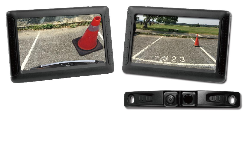
1. The Multi-Angle Wireless Camera System
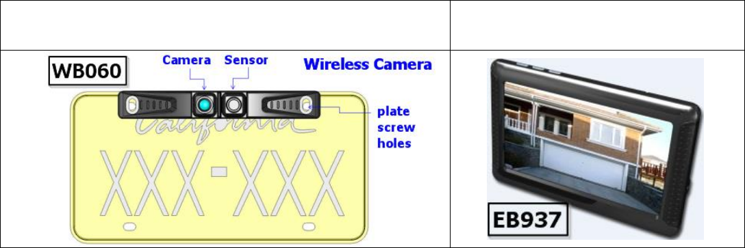
1.1. Parts
Wireless Camera
Wireless Receiver
The system spot movement—From left to right/ up to down
The system spot movement is marked with yellow frame
The system will display a yellow mark or icon when setting is confirmed
1.2. Information
Product compliant with FCC/CE rules.
Wireless technology WiFi 2.4GHz, IEEE802.11b/g.
Plug and play without paring @ auto power on.
Operating voltage DC 9V〜32V.
Operation temperature -10℃〜+70℃.
Storage temperature -30℃〜+70℃.
Operation distance around 167 feet.
4.3″ 480x272 high resolution LCD monitor.
LCD monitor brightness is adjustable, 8 levels.
Image quality 30fps @ VGA resolution.
Super view angle H=175∘.
Minimum illumination 0.1lux.
Quick boot up system around 1sec.
Shortest Image latency around 100ms.
Parking guide-line adjustable.
Water proof.
Ultrasonic distance detection.
Normal view & Top down view auto switching.
2. Introduction
2.1.
Multi-Angle Wireless Camera is installed on the tail of the automobile. When
you put into reverse gear, the system will operate automatically. You can
monitor the environment through the screen when you are reversing. Besides,
Wireless Camera is equipped with 58kHz ultrasonic device. When approaching
obstacles around 120cm. It will switch to Top-Down View automatically.
Multi-Angle wireless camera with 58kHz ultrasonic sensor
LCD: 4.3” WQVGA(480 × 272)
Pairing(default)
Parking line auto switch on/off
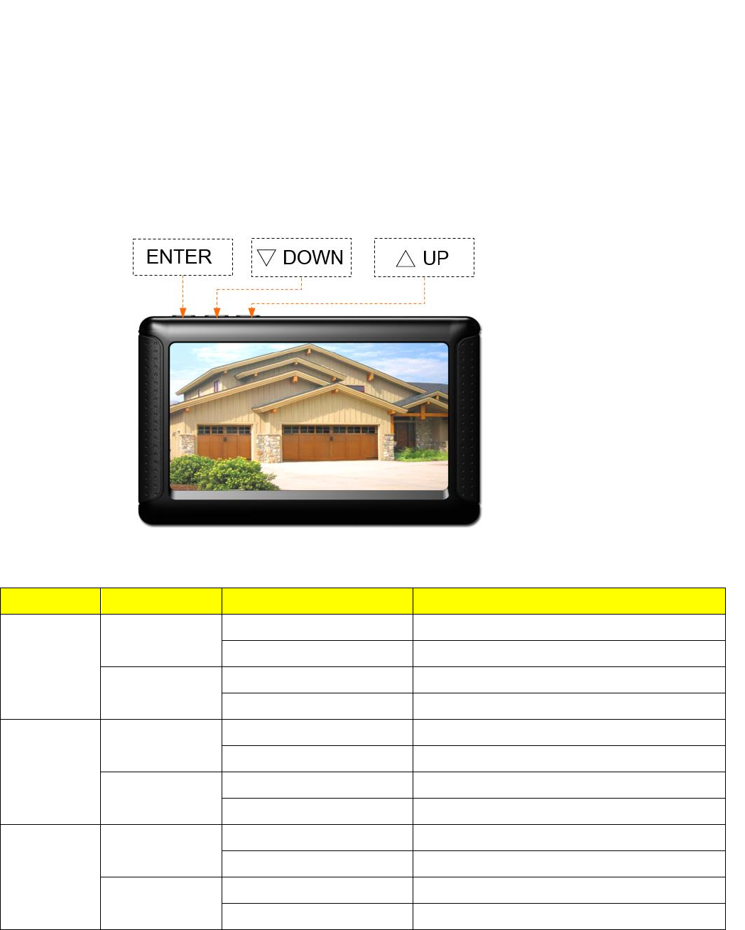
Switch unit user’s guide
Button
Mode
Press
Function
Enter
Normal
Long press 5 seconds
Into setting mode - Settings Menu
Short press
Turn the guiding line ON/OFF
Setting
Long press 5 seconds
N/A
Short press
Choose
▽
Normal
Long press 5 seconds
N/A
Short press
N/A
Setting
Long press 5 seconds
N/A
Short press
Down/Right
△
Normal
Long press 5 seconds
N/A
Short press
N/A
Setting
Long press 5 seconds
N/A
Short press
Up/Left
2.2. Interface
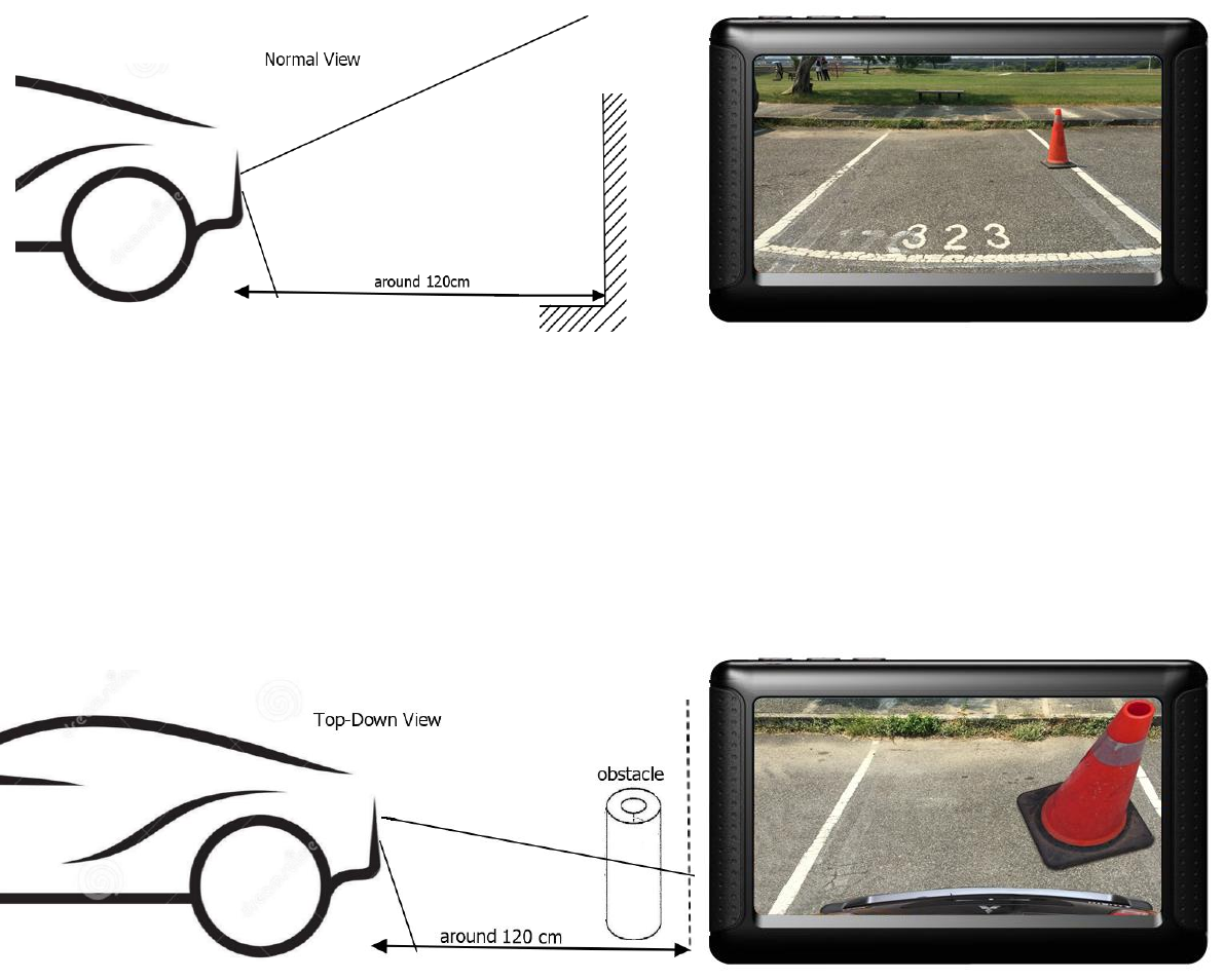
2.2.1. Normal View / Top-Down View
Wireless Camera can detect the distance and switch into Normal View / Top-Down
View automatically.
When obstacles is further than 120cm will display normal view:
When approaching obstacles around 120cm. It will switch to Top-Down View
automatically:
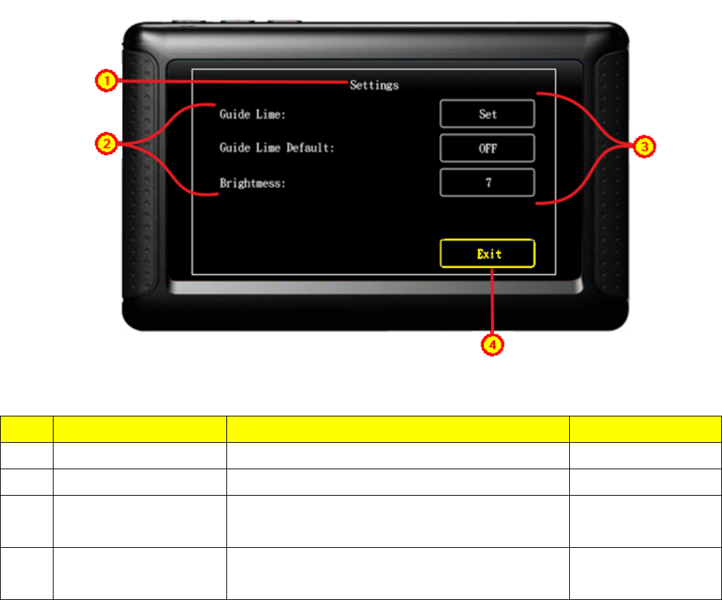
2.2.2. Settings
Note:
This system use high brightness/yellow to mark the content. See
above[Exit]
Contents:
2.2.2.1 Guide Line
2.2.2.2 Guide Line Default
2.2.2.3 Brightness
No
Name
Function
Switch Unit
1
Settings
Menu
N/A
2
Setting item
Setting title
N/A
3
Setting item
corresponding button
a. Setting item corresponding button
b. High brightness display when setted
YES
4
Exit
a. High brightness display when setted
b. Back to Camera mode
YES,Default
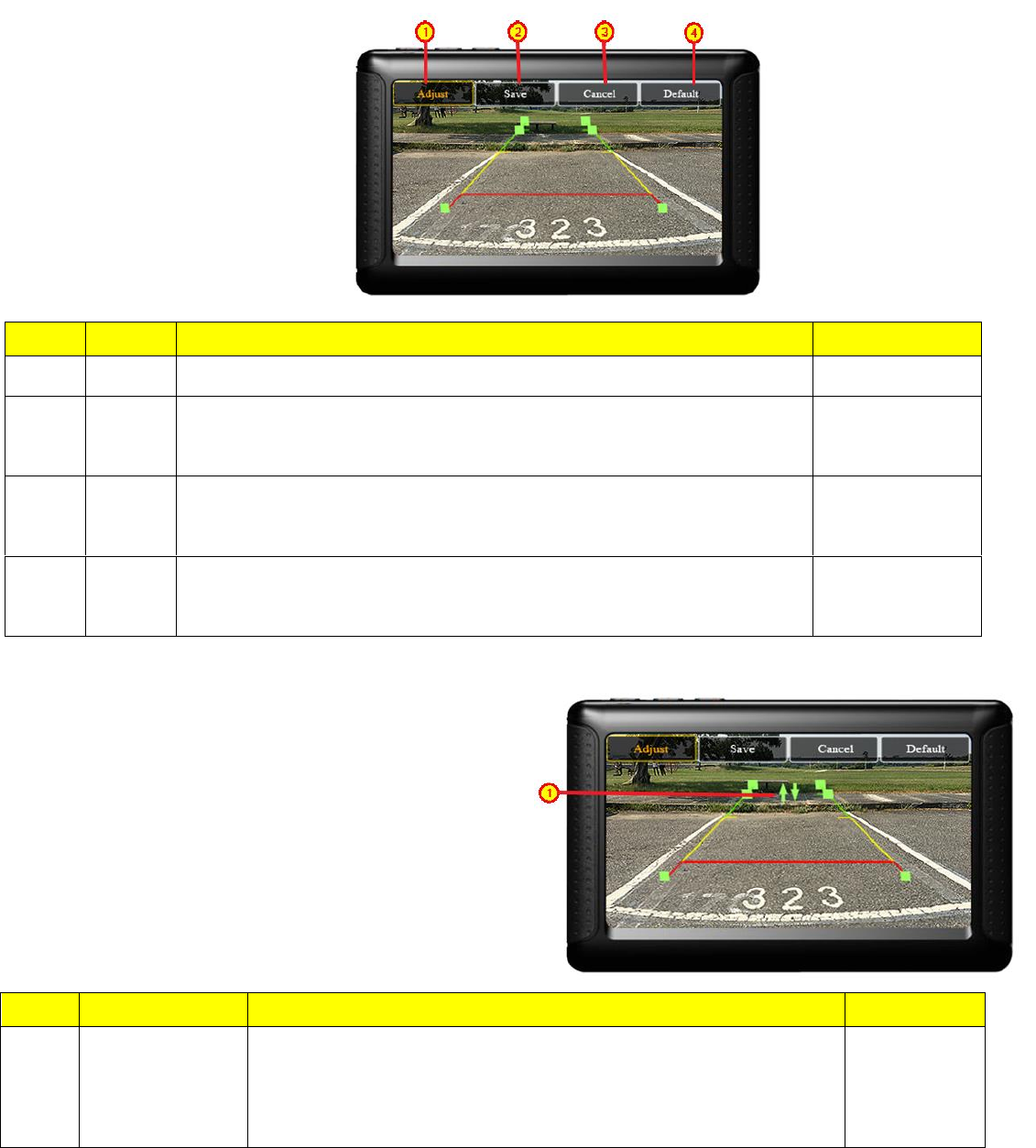
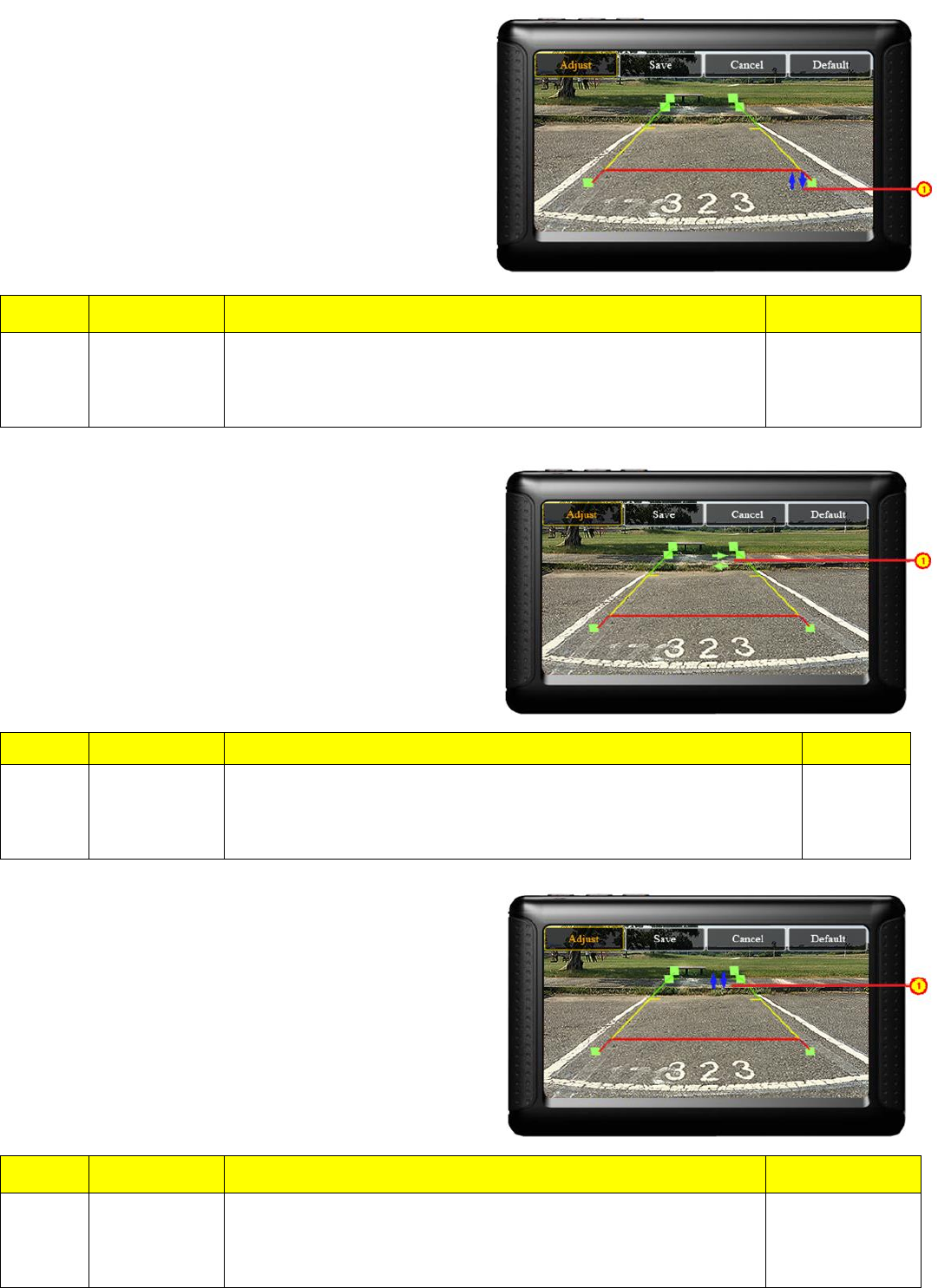
Guide Line
Guide line setting/display. Buttons function
(1)Guide Line Setting
A. Adjustment of the guiding line position.
No
Name
Function
Switch Unit
1
Adjust
Press ENTER and adjust the guide line
YES,Default
2
Save
Press△、▽ Key to move the spot into position[Guide Line] [Save]、
Press ENTER and saved, then exit setting.
YES
3
Cancel
Press△、▽ Key to move the spot into position[Guide Line] [Cancel]、
Press ENTER and not Saved, then exit setting
YES
4
Default
Press△、▽ Key to move the spot into position[Guide Line] [Default]、
Press ENTER, then back to default setting.
YES
No
Name
Function
Switch Unit
1
Adjustment
Press △ Key moved up for one pixel.
Press ▽ Key moved down for one pixel.
Press ENTER Key switch to next adjustment point(position)
YES
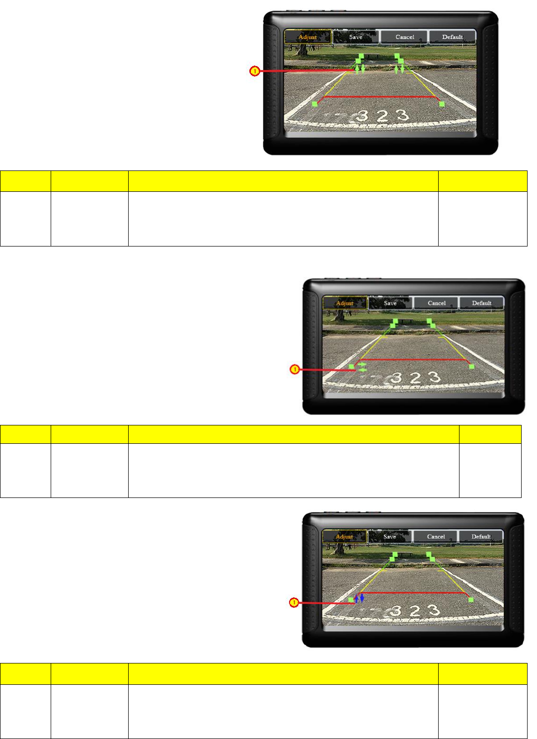
B. Guide line adjustment (horizontal)
C. Left side guide line front point adjustment
No
Name
Function
Switch Unit
1
Adjustment
Press △ Key moved up for one pixel.
Press ▽ Key moved down for one pixel.
Press ENTER Key switch to next adjustment point(position)
YES
No
Name
Function
Switch Unit
1
Adjustment
Press △ Key moved right for one pixel.
Press ▽ Key moved left for one pixel.
Press Switch Unit ENTER Key to adjust up/down for the guide point.
YES
No
Name
Function
Switch Unit
1
Adjustment
Press △ Key moved up for one pixel.
Press ▽ Key moved down for one pixel.
Press ENTER Key switch to next adjustment point(position)
YES
D. Left side guide line back point adjustment
E. Right side guide line front point adjustment
No
Name
Function
Switch Unit
1
Adjustment
Press △ Key moved right for one pixel.
Press ▽ Key moved left for one pixel.
Press Switch Unit ENTER Key to adjust up/down for the guide point.
YES
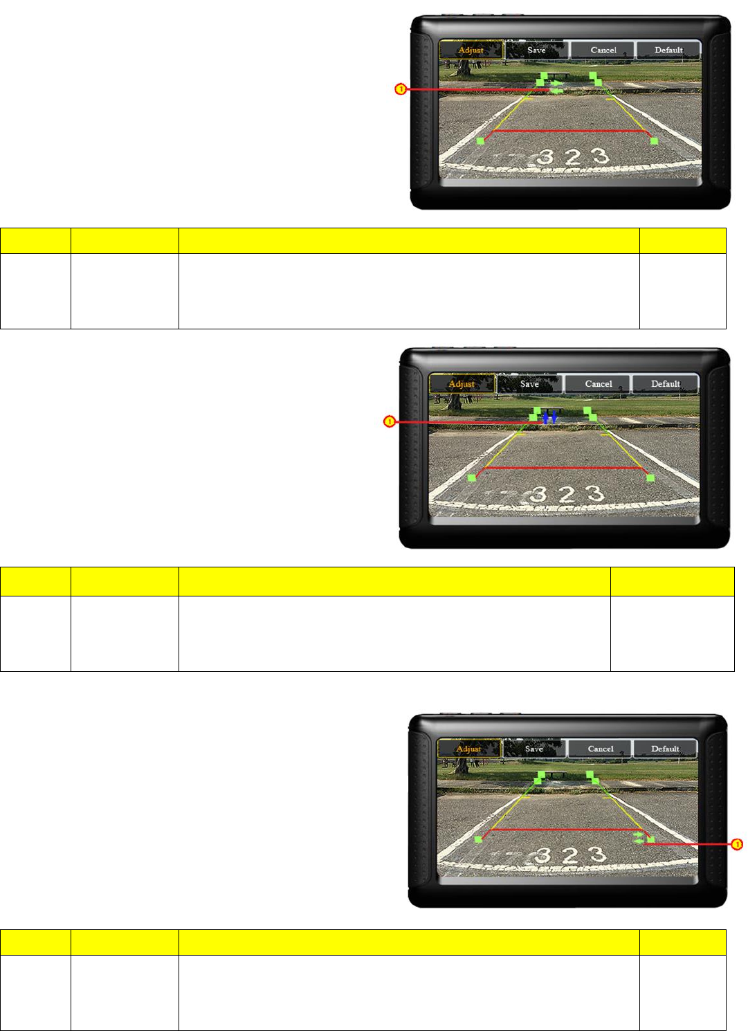
No
Name
Function
Switch Unit
1
Adjustment
Press △ Key moved up for one pixel.
Press ▽ Key moved down for one pixel.
Press ENTER Key switch to next adjustment point(position)
YES
No
Name
Function
Switch Unit
1
Adjustment
Press △ Key moved right for one pixel.
Press ▽ Key moved left for one pixel.
Press Switch Unit ENTER Key to adjust up/down for the guide point.
YES
F. Right side guide line back point adjustment
No
Name
Function
Switch Unit
1
Adjustment
Press △ Key moved up for one pixel.
Press ▽ Key moved down for one pixel.
Press ENTER Key switch to next adjustment point(position)
YES
No
Name
Function
Switch Unit
1
Adjustment
Press △ Key moved right for one pixel.
Press ▽ Key moved left for one pixel.
Press Switch Unit ENTER Key to adjust up/down for the guide point.
YES
No
Name
Function
Switch Unit
1
Adjustment
Press △ Key moved up for one pixel.
Press ▽ Key moved down for one pixel.
Press ENTER Key switch to next adjustment point(position)
YES
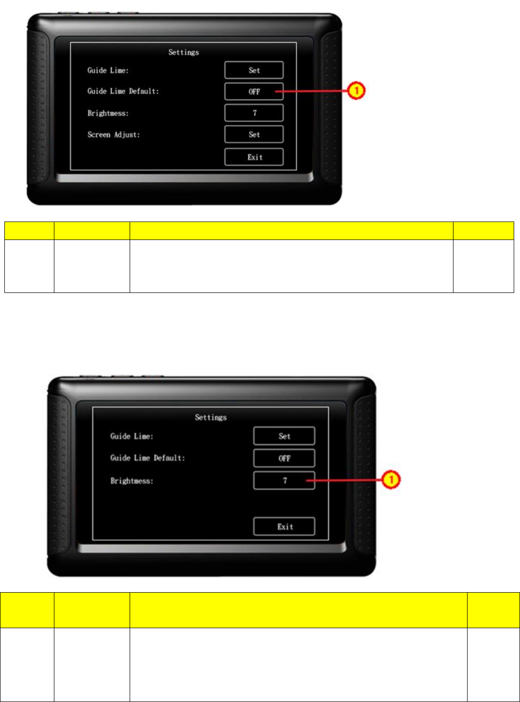
2.2.2.2 Guide Line Default
2.2.2.3 Brightness
No
Name
Function
Switch Unit
1
ON / OFF
Press Enter Key to change the display
ON: Guide line display on.
OFF: Guide line display off.
YES
No
Name
Function
Switch
Unit
1
Brightness
a. Adjustment the brightness press△、▽ key,press△ to
increase,press▽to decrease the level of brightness
b. Brightness level from 1~8, brighter as level increased
c. Default setting as 7
YES
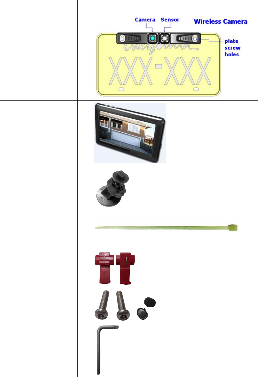
3. Product and accessories.
Name
Items
Wireless Camera
Wireless Receiver
Stand
Cable tie
Wire clip
Screws & Cover
Screwdriver
4. Precautions.
Parking system just for reference only, for your safety, please confirm
the actual surroundings.
Please pay attention to camera installation, red line then positive,
black line then negative.
This product is waterproof, do not rinse directly with water cannons.
Ultrasonic sensor distance range is around 120cm
If Sensor dysfunction, try adjusting the angle of the probe.
“USER MANUAL” Compliance Statement § 15.21 &
15.105
EB937 FCC ID:2AJNIEB937
WB060 FCC ID:2AJNIWB060
FEDERAL COMMUNICATIONS COMMISSION
INTERFERENCE STATEMENT
This equipment has been tested and found to comply with the limits for a Class B
digital device, pursuant to Part 15 of the FCC Rules. These limits are designed to
provide reasonable protection against harmful interference in a residential installation.
This equipment generates, uses and can radiate radio frequency energy and, if not
installed and used in accordance with the instructions, may cause harmful
interference to radio communications. However, there is no guarantee that
interference will not occur in a particular installation. If this equipment does cause
harmful interference to radio or television reception, which can be determined by
turning the equipment off and on, the user is encouraged to try to correct the
interference by one or more of the following measures:
-- Reorient or relocate the receiving antenna.
-- Increase the separation between the equipment and receiver.
-- Connect the equipment into an outlet on a circuit different from that to which the
receiver is connected.
-- Consult the dealer or an experienced radio/TV technician for help.
CAUTION:
To assure continued FCC compliance:
Any changes or modifications not expressly approved by the grantee of this device
could void the user's authority to operate the equipment.
This device complies with Part 15 of the FCC Rules. Operation is subject to the
following two conditions:
(1) This device may not cause harmful interference, and
(2) this device must accept any interference received, including interference that may
cause undesired operation.
CAUTION:
To assure continued FCC compliance:
1. Any changes or modifications not expressly approved by the grantee of this device could
void the user's authority to operate the equipment.
2. This equipment complies with FCC radiation exposure limits set forth for an uncontrolled
environment. This equipment should be installed and operated with minimum distance
20cm between the radiator & your body.