Fostex Vm200 Users Manual Page
VM200 to the manual fed4a860-4525-4f5a-b4f2-d1b553591636
2015-02-02
: Fostex Fostex-Vm200-Users-Manual-428138 fostex-vm200-users-manual-428138 fostex pdf
Open the PDF directly: View PDF ![]() .
.
Page Count: 234 [warning: Documents this large are best viewed by clicking the View PDF Link!]
- TableContentsFIXED2.pdf
- 01Intro.pdf
- 02Tour.pdf
- CHAPTER 2 Touring the VM200
- About This Chapter
- Chapter Contents
- Top Panel Control Surface
- Analog Control Section
- LCD Display
- Data Wheel and Neighboring Keys
- Function Keys
- Setup Section
- Current Scene Status
- Key Mode Section
- Fader Mode Section
- Selected EQ Section
- EQ Library
- Eff Edit Section
- Rec Buss Section
- Scene Memory Section
- Channel Control Section
- Rear Panel
- Block Diagram
- 03GettingStarted.pdf
- 04Input.pdf
- CHAPTER 4 Input Channels
- About This Chapter
- Chapter Contents
- Input Channels 1–4
- Input Channels 5–8
- Input Channels 9–16
- Input Channels 17–20
- Insert Channels 1–4
- Pad Switches (Input channels 1–4)
- TRIM Controls
- Inverting the Input Phase
- Input Channel EQ
- Muting Channels
- Setting Channel Levels
- Panning Input Channels
- Routing Input Channels
- Monitoring and Soloing Input Channels
- Feeding Outputs
- Pairing Channels
- Grouping Mute Channels
- Grouping Faders
- Viewing Input Channel Settings
- Copying Channel Settings
- 05EQ.pdf
- 06Monitoring.pdf
- 07Outputs.pdf
- 08Effects.pdf
- CHAPTER 8 Effects
- About This Chapter
- Chapter Contents
- VM200 Effects
- Effects Library
- Effect Preset Library List
- Applying Effects
- Controlling the Sends Signals
- Controlling the Return Signals
- Effects Library
- Editing Effects
- Recalling Effects Programs
- Storing Effects Programs
- Editing Effect Program Titles
- Effects Parameters
- 09Scenes.pdf
- 10DigitalIO.pdf
- 11MIDI chapter.pdf
- CHAPTER 11 VM200 & MIDI
- About This Chapter
- Chapter Contents
- Using the VM200 with MIDI
- MIDI Ports
- MIDI Transmit and Receive Channels
- Using Program Change Messages to Recall Scenes
- Using Control Change Messages
- Controlling Parameters Using Fostex Exclusive Messages
- Bulk Dump
- MMC (MIDI Machine Control) Send
- 12Initialize.pdf
- Appendix.pdf
- Chapter Contents
- Display Warning Messages
- Specifications
- Maintenance
- Tables & Data
- Program Change To Scene Memory Assignment Tables
- Control Change To Control Parameters Assignment Tables
- Preset Scene Parameters
- MIDI In/Out Data Format
- Declaration of EC Directive
- The Affect of Immunity on This Equipment
- Fostex Distributors List In Europe
- Index.pdf
INPUT 4INPUT 3INPUT 2INPUT 1
PAD
26dB
A
B
PAD
26dB
A
B
PAD
26dB
A
B
PAD
26dB
A
B
-16 -60
+10 -34
-16 -60
+10 -34
-16 -60 -16 -60
TRIMTRIMTRIMTRIM
DIGITAL RECORDING MIXER
VM200
SCENE MEMORYREC BUSS
EFF EDITSELECTED EQ
EQ/HI
EQ/HI-MIDEQ/LO-MIDEQ/LOSETUP
CURRENT SCENE STATUS
KEY MODE
+10
0
-10
-20
-30
-40
-
+10
0
-10
-20
-30
-40
-
+10
0
-10
-20
-30
-40
-
+10
0
-10
-20
-30
-40
-
+10
0
-10
-20
-30
-40
-
+10
0
-10
-20
-30
-40
-
+10
0
-10
-20
-30
-40
-
16
8
GAIN
FREQ
PAN
Q
PAN
ON ON ON ON ON ON ON
SOLO SOLO SOLO SOLO SOLO SOLO SOLO
EQ EDIT EQ EDIT EQ EDIT EQ EDIT EQ EDIT EQ EDIT EQ EDIT EQ EDIT
SOLO
ON ON
SOLO
EQ LIBRARY
STORERECALL
EQ ON
EFF LIBRARY
STORERECALL
EFF2EFF1
STORERECALLSOLO
+1/ /-1
DATA
EXIT
ENTER
MASTER
15
7
14
6
13
5
12
4
11
3
10
2
9
1
2019
18
17
FREQ QFREQ Q
FREQ Q
GAINGAINGAIN
1-8 ANALOG IN 9-16 ADAT IN 17-20 EFF RTN
PAGE SELECT
SYSTEM MIDI
PHASE GROUP
ROUTING/ PAIR/
CH VIEW METER
CHANNEL/
AUX1
FADER MODE
AUX2
AUX3 AUX4
EFF1 EFF2
CHANNEL
ADD.AUX
TRIM
-10 -50
TRIM TRIM TRIM
-10 -50 -10 -50 -10 -50
INPUT 5 INPUT 6 INPUT 7 INPUT 8
MIN MAX
GAIN
MAXMIN
GAIN
2TRK IN
PHONESMONITOR
+10
0
-10
-20
-30
-40
-
EFF RTN
ADAT IN
ANALOG IN
0
-10
-20
-30
-60
-
-40
MMC SEND
PANPANPANPA NPANPAN
-48
-36
-24
-18
-12
-9
-6
-3
OL
ST BUSS/SOLO
LR
METER
+10 -34 +10 -34
VM200
DIGITAL RECORDING MIXER
USER’S GUIDE
CAUTION: TO REDUCE THE RISK OF ELECTRIC SHOCK,
DO NOT REMOVE COVER (OR BACK).
NO USER - SERVICEABLE PARTS INSIDE.
REFER SERVICING TO QUALIFIED SERVICE PERSONNEL.
CAUTION
RISK OF ELECTRIC SHOCK
DO NOT OPEN
"WARNING"
"TO REDUCE THE RISK OF FIRE OR ELECTRIC SHOCK,
DO NOT EXPOSE THIS APPLIANCE TO RAIN OR
MOISTURE."
SAFETY INSTRUCTIONS
1. Read Instructions - All the safety and operating instructions
should be read before the appliance is operated.
2. Retain Instructions - The safety and operating instructions
should be retained for future reference.
3. Heed Warnings - All warnings on the appliance and in the
operating instructions should be adhered to.
4. Follow Instructions - All operating and use instructions should
be followed.
5. Water and Moisture - The appliance should not be used near
water - for example, near a bathtub, washbowl, kitchen sink,
laundry tub, in a wet basement, or near a swimming pool, and
the like.
6. Carts and Stands - The appliance should be used only with a
cart or stand that is recommended by the manufacturer.
9. Heat - The appliance should be situated away from heat sources
such as radiators, heat registers, stoves, or other appliances
(including amplifiers) that produce heat.
10. Power Sources - The appliance should be connected to a power
supply only of the type described in the operating instructions
or as marked on the appliance.
11. Grounding or Polarization - The precautions that should be taken
so that the grounding or polarization means of an appliance is
not defeated.
12. Power Cord Protection - Power supply cords should be routed
so that they are not likely to be walked on or pinched by items
placed upon or against them, paying particular attention to cords
at plugs, convenience receptacles, and the point where they
exit from the appliance.
13. Cleaning - The appliance should be cleaned only as
recommended by the manufacturer.
14. Nonuse Periods - The power cord of the appliance should be
unplugged from the outlet when left unused for a long period of
time.
15. Object and Liquid Entry - Care should be taken so that objects
do not fall and liquids are not spilled into the enclosure through
openings.
16. Damage Requiring Service - The appliance should be serviced
by qualified service personnel when:
A. The power supply cord or the plug has been damaged; or
B. Objects have fallen, or liquid has been spilled into the
appliance; or
C. The appliance has been exposed to rain; or
D. The appliance does not appear to operate normally or
exhibits a marked change in performance; or
E. The appliance has been dropped, or the enclosure damaged.
17. Servicing - The user should not attempt to service the appliance
beyond that described in the operating instructions.
All other servicing should be referred to qualified service
personnel.
The lightning flash with arrowhead symbol, within an equilateral
triangle, is intended to alert the user to the presence of uninsulated
"dangerous voltage" within the product's enclosure that may be
of sufficient magnitude to constitute a risk of electric shock to
persons.
The exclamation point within an equilateral triangle is intended to
alert the user to the presence of important operating and
maintenance (servicing) instructions in the literature
accompanying the appliance.
CAUTION:
TO PREVENT ELECTRIC SHOCK, MATCH WIDE BLADE OF
PLUG TO WIDE SLOT, FULLY INSERT.
ATTENTION:
POUR EVITER LES CHOCS ELECTRIQUES, INTRODUIRE
LA LAME LA PLUS LARGE DE LA FICHE DANS LA BORNE
CORRESPONDANTE DE LA PRISE ET POUSSER JUSQU'
AU FOND.
An appliance and cart combination should be moved with care.
Quick stops, excessive force, and uneven surfaces may cause
the appliance and cart combination to overturn.
7. Wall or Ceiling Mounting - The appliance should be mounted to
a wall or ceiling only as recommended by the manufacturer.
8. Ventilation - The appliance should be situated so that its location
or position dose not interfere with its proper ventilation.
For example, the appliance should not be situated on a bed,
sofa, rug, or similar surface that may block the ventilation
openings; or, placed in a built-in installation, such as a bookcase
or cabinet that may impede the flow of air through the ventilation
openings.

VM200 User’s Guide 3
DIGITAL RECORDING MIXER
VM200
REC BUSS
EFF EDITSELECTED EQ
+10
0
-10
-20
-30
-40
+10
0
-10
20
+10
0
0
PAN
ON
OO
EQ EDIT
SOLO
ON ON
SOLO
EQ LIBRARY
STORERECALL
EQ ON
EFF
LI
EFF
LI
RECALL
EFF1
SOLO
MIN MAX MIN
0
-10
-20
-30
-
40
-
40
Table of Contents
CHAPTER 1
Introducing the VM200. . . . . . . . . . . . . . . . . . . . .9
About This Chapter. . . . . . . . . . . . . . . . . . . . . . . . . . . .9
Chapter Contents . . . . . . . . . . . . . . . . . . . . . . . . . . . . .9
Welcome to the VM200 . . . . . . . . . . . . . . . . . . . . . . . .10
Using this Guide. . . . . . . . . . . . . . . . . . . . . . . . . . . . .10
Installing the VM200. . . . . . . . . . . . . . . . . . . . . . . . . .11
Feature Summary. . . . . . . . . . . . . . . . . . . . . . . . . . . .12
Audio Specifications . . . . . . . . . . . . . . . . . . . . . . . . . .12
Inputs and Outputs . . . . . . . . . . . . . . . . . . . . . . . . . .12
MIDI functions . . . . . . . . . . . . . . . . . . . . . . . . . . . . . .13
Why a Digital Mixer?. . . . . . . . . . . . . . . . . . . . . . . . . .14
Dual On-board Effects Processors. . . . . . . . . . . . . . . .15
Digital I/O . . . . . . . . . . . . . . . . . . . . . . . . . . . . . . . . .15
About the Display and Graphic User Interface. . . . . . .15
MIDI . . . . . . . . . . . . . . . . . . . . . . . . . . . . . . . . . . . . . .16
Faders . . . . . . . . . . . . . . . . . . . . . . . . . . . . . . . . . . . .16
CHAPTER 2
Touring the VM200. . . . . . . . . . . . . . . . . . . . . . .17
About This Chapter. . . . . . . . . . . . . . . . . . . . . . . . . . .17
Chapter Contents . . . . . . . . . . . . . . . . . . . . . . . . . . . .17
Top Panel Control Surface. . . . . . . . . . . . . . . . . . . . . .18
Analog Control Section . . . . . . . . . . . . . . . . . . . . . . . .19
LCD Display . . . . . . . . . . . . . . . . . . . . . . . . . . . . . . . .20
Data Wheel and Neighboring Keys. . . . . . . . . . . . . . . .21
[</-1] and [+1/>] Keys. . . . . . . . . . . . . . . . . . . . . . . . .21
[ENTER] and [EXIT] Keys. . . . . . . . . . . . . . . . . . . . . . .21
Function Keys. . . . . . . . . . . . . . . . . . . . . . . . . . . . . . .22
Setup Section . . . . . . . . . . . . . . . . . . . . . . . . . . . . . . .23
[SYSTEM] Key. . . . . . . . . . . . . . . . . . . . . . . . . . . . . . .23
[MIDI] Key. . . . . . . . . . . . . . . . . . . . . . . . . . . . . . . . . .23
Current Scene Status . . . . . . . . . . . . . . . . . . . . . . . . .24
Key Mode Section . . . . . . . . . . . . . . . . . . . . . . . . . . . .24
[ROUTING/PHASE] Key. . . . . . . . . . . . . . . . . . . . . . . .24
[PAIR/GROUP] Key . . . . . . . . . . . . . . . . . . . . . . . . . . .25
[CH VIEW] Key . . . . . . . . . . . . . . . . . . . . . . . . . . . . . .25
[CHANNEL/METER] Key . . . . . . . . . . . . . . . . . . . . . . .26
Fader Mode Section. . . . . . . . . . . . . . . . . . . . . . . . . . .27
[AUX1], [AUX2], [AUX3], and [AUX4] Keys . . . . . . . . . .27
[EFF1] and [EFF2] Keys. . . . . . . . . . . . . . . . . . . . . . . .27
[CHANNEL] Key. . . . . . . . . . . . . . . . . . . . . . . . . . . . . .27
Selected EQ Section . . . . . . . . . . . . . . . . . . . . . . . . . .28
[EQ ON] Key . . . . . . . . . . . . . . . . . . . . . . . . . . . . . . . .28
EQ Library . . . . . . . . . . . . . . . . . . . . . . . . . . . . . . . . .28
[RECALL] Key . . . . . . . . . . . . . . . . . . . . . . . . . . . . . . .28
Eff Edit Section. . . . . . . . . . . . . . . . . . . . . . . . . . . . . .29
[EFF1] and [EFF2] Keys. . . . . . . . . . . . . . . . . . . . . . . .29
Effect Library . . . . . . . . . . . . . . . . . . . . . . . . . . . . . . .29
[RECALL] Key . . . . . . . . . . . . . . . . . . . . . . . . . . . . . . .30
[STORE] Key . . . . . . . . . . . . . . . . . . . . . . . . . . . . . . . .30
Rec Buss Section . . . . . . . . . . . . . . . . . . . . . . . . . . . .30
Scene Memory Section . . . . . . . . . . . . . . . . . . . . . . . .31
[RECALL] Key . . . . . . . . . . . . . . . . . . . . . . . . . . . . . . .31
[STORE] Key . . . . . . . . . . . . . . . . . . . . . . . . . . . . . . . .31
Channel Control Section . . . . . . . . . . . . . . . . . . . . . . .32
Faders . . . . . . . . . . . . . . . . . . . . . . . . . . . . . . . . . . . .32
[ON] Keys . . . . . . . . . . . . . . . . . . . . . . . . . . . . . . . . . .34

4 VM200 User’s Guide
[ON] key function . . . . . . . . . . . . . . . . . . . . . . . . . . . . 34
EQ Section Rotary Controls . . . . . . . . . . . . . . . . . . . . 36
Rear Panel . . . . . . . . . . . . . . . . . . . . . . . . . . . . . . . . . 38
Block Diagram . . . . . . . . . . . . . . . . . . . . . . . . . . . . . . 41
CHAPTER 3
Getting Started . . . . . . . . . . . . . . . . . . . . . . . . . .43
About This Chapter . . . . . . . . . . . . . . . . . . . . . . . . . . 43
Chapter Contents. . . . . . . . . . . . . . . . . . . . . . . . . . . . 43
VM200 System Example. . . . . . . . . . . . . . . . . . . . . . . 44
Connecting the Power Cord . . . . . . . . . . . . . . . . . . . . 45
Turning the VM200 On and Off . . . . . . . . . . . . . . . . . 45
A Few Tips on Using the VM200. . . . . . . . . . . . . . . . . 46
Channel Layers . . . . . . . . . . . . . . . . . . . . . . . . . . . . . 46
An Important Note About Word Clock Information . . . 48
Stopless Rotary Controls . . . . . . . . . . . . . . . . . . . . . . 48
Reading the Display . . . . . . . . . . . . . . . . . . . . . . . . . . 49
The Channel Edit Function Page . . . . . . . . . . . . . . . . 49
Function Page Parameter Matrix. . . . . . . . . . . . . . . . . 50
Lit & Flashing LED Keys. . . . . . . . . . . . . . . . . . . . . . . 51
Finally...Let’s Get Started! . . . . . . . . . . . . . . . . . . . . . 52
Making Connections. . . . . . . . . . . . . . . . . . . . . . . . . . 52
Powering On. . . . . . . . . . . . . . . . . . . . . . . . . . . . . . . . 53
Adjusting the Channel Input . . . . . . . . . . . . . . . . . . . 53
Recording. . . . . . . . . . . . . . . . . . . . . . . . . . . . . . . . . . 57
Storing a Mix Scene . . . . . . . . . . . . . . . . . . . . . . . . . . 57
CHAPTER 4
Input Channels . . . . . . . . . . . . . . . . . . . . . . . . . .59
About This Chapter . . . . . . . . . . . . . . . . . . . . . . . . . . 59
Chapter Contents. . . . . . . . . . . . . . . . . . . . . . . . . . . . 59
Input Channels 1–4 . . . . . . . . . . . . . . . . . . . . . . . . . . 60
Input Channels 5–8 . . . . . . . . . . . . . . . . . . . . . . . . . . 61
Input Channels 9–16 . . . . . . . . . . . . . . . . . . . . . . . . . 61
Input Channels 17–20 . . . . . . . . . . . . . . . . . . . . . . . . 61
Insert Channels 1–4 . . . . . . . . . . . . . . . . . . . . . . . . . . 62
Pad Switches (Input channels 1–4) . . . . . . . . . . . . . . . 63
TRIM Controls . . . . . . . . . . . . . . . . . . . . . . . . . . . . . . 63
Inverting the Input Phase. . . . . . . . . . . . . . . . . . . . . . 64
Input Channel EQ . . . . . . . . . . . . . . . . . . . . . . . . . . . 65
Muting Channels . . . . . . . . . . . . . . . . . . . . . . . . . . . . 65
Setting Channel Levels. . . . . . . . . . . . . . . . . . . . . . . . 65
Panning Input Channels. . . . . . . . . . . . . . . . . . . . . . . 65
Routing Input Channels . . . . . . . . . . . . . . . . . . . . . . . 66
Monitoring and Soloing Input Channels . . . . . . . . . . . 67
Feeding Outputs . . . . . . . . . . . . . . . . . . . . . . . . . . . . 67
REC Buss Out . . . . . . . . . . . . . . . . . . . . . . . . . . . . . . 67
ST Buss Out. . . . . . . . . . . . . . . . . . . . . . . . . . . . . . . . 67
AUX Sends. . . . . . . . . . . . . . . . . . . . . . . . . . . . . . . . . 67
Pairing Channels . . . . . . . . . . . . . . . . . . . . . . . . . . . . 68
Grouping Mute Channels . . . . . . . . . . . . . . . . . . . . . . 68
Grouping Faders . . . . . . . . . . . . . . . . . . . . . . . . . . . . 69
Viewing Input Channel Settings . . . . . . . . . . . . . . . . . 70
Copying Channel Settings . . . . . . . . . . . . . . . . . . . . . 72
CHAPTER 5
EQ. . . . . . . . . . . . . . . . . . . . . . . . . . . . . . . . . . . .75
About This Chapter . . . . . . . . . . . . . . . . . . . . . . . . . . 75
Chapter Contents. . . . . . . . . . . . . . . . . . . . . . . . . . . . 75
Equalizers (EQ) . . . . . . . . . . . . . . . . . . . . . . . . . . . . . 76

VM200 User’s Guide 5
Adjusting the EQ . . . . . . . . . . . . . . . . . . . . . . . . . . . .77
EQ Enabling Channels . . . . . . . . . . . . . . . . . . . . . . . .80
Bypassing the EQ . . . . . . . . . . . . . . . . . . . . . . . . . . . .80
Resetting the EQ. . . . . . . . . . . . . . . . . . . . . . . . . . . . .81
EQ Library . . . . . . . . . . . . . . . . . . . . . . . . . . . . . . . . .83
EQ Preset Library List. . . . . . . . . . . . . . . . . . . . . . . . .83
Recalling EQ Programs . . . . . . . . . . . . . . . . . . . . . . . .84
Storing EQ Programs . . . . . . . . . . . . . . . . . . . . . . . . .86
Editing EQ Program Titles. . . . . . . . . . . . . . . . . . . . . .88
Copying EQ Settings . . . . . . . . . . . . . . . . . . . . . . . . . .90
EQ Preset Library Parameters . . . . . . . . . . . . . . . . . . .92
CHAPTER 6
Monitoring Signals. . . . . . . . . . . . . . . . . . . . . . .97
About This Chapter. . . . . . . . . . . . . . . . . . . . . . . . . . .97
Chapter Contents . . . . . . . . . . . . . . . . . . . . . . . . . . . .97
Monitoring and Soloing. . . . . . . . . . . . . . . . . . . . . . . .98
MON SEL Parameter . . . . . . . . . . . . . . . . . . . . . . . . . .98
SOLO MODE Parameter . . . . . . . . . . . . . . . . . . . . . . .98
Monitor Outs and Phones . . . . . . . . . . . . . . . . . . . . . .99
Two Track Input (2TRK IN) . . . . . . . . . . . . . . . . . . . . .99
Monitoring . . . . . . . . . . . . . . . . . . . . . . . . . . . . . . . .100
Soloing . . . . . . . . . . . . . . . . . . . . . . . . . . . . . . . . . . .101
Metering Signal Levels. . . . . . . . . . . . . . . . . . . . . . . .105
Viewing Input/Output Level Meters. . . . . . . . . . . . . .105
Viewing Channel, Aux Send & Effect Send Meters. . .106
CHAPTER 7
Outputs . . . . . . . . . . . . . . . . . . . . . . . . . . . . . . .107
About This Chapter. . . . . . . . . . . . . . . . . . . . . . . . . .107
Chapter Contents . . . . . . . . . . . . . . . . . . . . . . . . . . .107
Overview. . . . . . . . . . . . . . . . . . . . . . . . . . . . . . . . . .108
ST BUSS OUT. . . . . . . . . . . . . . . . . . . . . . . . . . . . . .108
REC BUSS OUT . . . . . . . . . . . . . . . . . . . . . . . . . . . .108
ADAT OUT & S/P DIF OUT . . . . . . . . . . . . . . . . . . . .109
AUX SEND . . . . . . . . . . . . . . . . . . . . . . . . . . . . . . . .109
Using the ST BUSS OUT . . . . . . . . . . . . . . . . . . . . . .110
Monitoring the ST BUSS OUT . . . . . . . . . . . . . . . . . .110
Viewing the ST BUSS OUT Meters. . . . . . . . . . . . . . .110
Setting the ST BUSS OUT Level. . . . . . . . . . . . . . . . .111
Muting the ST BUSS OUT . . . . . . . . . . . . . . . . . . . . .111
Using the REC BUSS OUT. . . . . . . . . . . . . . . . . . . . .112
Monitoring the REC BUSS OUT. . . . . . . . . . . . . . . . .112
Viewing the REC BUSS OUT Meters . . . . . . . . . . . . .112
Setting the REC BUSS OUT Level . . . . . . . . . . . . . . .113
Using the AUX Sends . . . . . . . . . . . . . . . . . . . . . . . .115
Enabling AUX Sends 3 & 4 (ADD. AUX Parameter) . .115
Monitoring AUX Sends . . . . . . . . . . . . . . . . . . . . . . .116
Viewing the AUX Send and Master Setting . . . . . . . .116
Pre-fader/Post-fader AUX Sends . . . . . . . . . . . . . . . .117
Muting AUX Sends . . . . . . . . . . . . . . . . . . . . . . . . . .118
Smoothing Function . . . . . . . . . . . . . . . . . . . . . . . . .120
Viewing Buss Routing for Each Channel . . . . . . . . . .121
CHAPTER 8
Effects . . . . . . . . . . . . . . . . . . . . . . . . . . . . . . . .123
About This Chapter. . . . . . . . . . . . . . . . . . . . . . . . . .123
Chapter Contents . . . . . . . . . . . . . . . . . . . . . . . . . . .123
VM200 Effects. . . . . . . . . . . . . . . . . . . . . . . . . . . . . .124
Effects Library . . . . . . . . . . . . . . . . . . . . . . . . . . . . .125

6 VM200 User’s Guide
Effect Preset Library List . . . . . . . . . . . . . . . . . . . . . 125
Applying Effects . . . . . . . . . . . . . . . . . . . . . . . . . . . . 128
Selecting an Effects Processor . . . . . . . . . . . . . . . . . 128
Setting Effects Return . . . . . . . . . . . . . . . . . . . . . . . 128
Sending Signal to Effects Processor . . . . . . . . . . . . . 129
Routing Effects Returns . . . . . . . . . . . . . . . . . . . . . . 129
Controlling the Sends Signals. . . . . . . . . . . . . . . . . . 130
Pre-fader/Post-fader Effect Sends. . . . . . . . . . . . . . . 130
Viewing and Adjusting the Effect Send Level. . . . . . . 130
Viewing and Adjusting the Effect Send Master Level . 131
Monitoring Effects Sends . . . . . . . . . . . . . . . . . . . . . 132
Controlling the Return Signals . . . . . . . . . . . . . . . . . 132
Setting the Effect Return Level . . . . . . . . . . . . . . . . . 132
Panning Effects Returns. . . . . . . . . . . . . . . . . . . . . . 132
Effects Library . . . . . . . . . . . . . . . . . . . . . . . . . . . . . 133
Editing Effects . . . . . . . . . . . . . . . . . . . . . . . . . . . . . 133
Recalling Effects Programs . . . . . . . . . . . . . . . . . . . . 134
Storing Effects Programs . . . . . . . . . . . . . . . . . . . . . 135
Editing Effect Program Titles . . . . . . . . . . . . . . . . . . 137
Effects Parameters . . . . . . . . . . . . . . . . . . . . . . . . . . 139
CHAPTER 9
Scene Memory . . . . . . . . . . . . . . . . . . . . . . . . .147
About This Chapter . . . . . . . . . . . . . . . . . . . . . . . . . 147
Chapter Contents. . . . . . . . . . . . . . . . . . . . . . . . . . . 147
What is Scene Memory? . . . . . . . . . . . . . . . . . . . . . . 148
Scene Edit Indicator. . . . . . . . . . . . . . . . . . . . . . . . . 149
What Can You Store in a Scene? . . . . . . . . . . . . . . . 149
Recalling Mix Scenes . . . . . . . . . . . . . . . . . . . . . . . . 151
Recalling a Scene Manually . . . . . . . . . . . . . . . . . . . 151
Recalling a Scene Automatically at Start-up . . . . . . . 151
Recalling Scenes Using MIDI Program Change . . . . . 152
Motorized Faders . . . . . . . . . . . . . . . . . . . . . . . . . . . 153
Storing Mix Scenes. . . . . . . . . . . . . . . . . . . . . . . . . . 154
Editing Scene Memory Titles. . . . . . . . . . . . . . . . . . . 156
Recall Safe Function. . . . . . . . . . . . . . . . . . . . . . . . . 156
Specifying Recall Safe Channels . . . . . . . . . . . . . . . . 156
Specifying Recall Safe Parameters . . . . . . . . . . . . . . 157
CHAPTER 10
Digital Connections . . . . . . . . . . . . . . . . . . . . .159
About This Chapter . . . . . . . . . . . . . . . . . . . . . . . . . 159
Chapter Contents. . . . . . . . . . . . . . . . . . . . . . . . . . . 159
Digital Connections, Word Clocks, and Sample Rates 160
Word Clock Setup . . . . . . . . . . . . . . . . . . . . . . . . . . 162
WORD IN/OUT Connectors . . . . . . . . . . . . . . . . . . . 162
Setting the Master Word Clock . . . . . . . . . . . . . . . . . 162
Setting the VM200 as Master or Slave . . . . . . . . . . . 163
Multitrack Recording and Mastering to a DAT . . . . . 164
Digital I/Os . . . . . . . . . . . . . . . . . . . . . . . . . . . . . . . 165
ADAT IN/OUT . . . . . . . . . . . . . . . . . . . . . . . . . . . . . 165
Using ADAT IN . . . . . . . . . . . . . . . . . . . . . . . . . . . . . 165
Assigning Channels to ADAT DIRECT SENDs. . . . . . 166
Using S/P DIF OUT . . . . . . . . . . . . . . . . . . . . . . . . . 168
Using S/P DIF IN . . . . . . . . . . . . . . . . . . . . . . . . . . . 169
Assigning S/P DIF Signals to Channels . . . . . . . . . . 169
Cascading the VM200 . . . . . . . . . . . . . . . . . . . . . . . 171

VM200 User’s Guide 7
CHAPTER 11
VM200 & MIDI . . . . . . . . . . . . . . . . . . . . . . . .173
About This Chapter. . . . . . . . . . . . . . . . . . . . . . . . . .173
Chapter Contents . . . . . . . . . . . . . . . . . . . . . . . . . . .173
Using the VM200 with MIDI . . . . . . . . . . . . . . . . . . .174
MIDI Ports . . . . . . . . . . . . . . . . . . . . . . . . . . . . . . . .174
Cascading Two VM200s . . . . . . . . . . . . . . . . . . . . . .175
MIDI Transmit and Receive Channels . . . . . . . . . . . .176
System Exclusive Messages (Fostex Exclusive) . . . . .179
Bulk Dump. . . . . . . . . . . . . . . . . . . . . . . . . . . . . . . .179
Using Program Change Messages to Recall Scenes . .180
Using Control Change Messages . . . . . . . . . . . . . . . .184
Editing the Control Change Assign Table. . . . . . . . . .185
Examples: Using Control Change Messages. . . . . . . .187
Controlling Parameters Using Fostex Exclusive . . . .188
Bulk Dump. . . . . . . . . . . . . . . . . . . . . . . . . . . . . . . .189
Transmitting MIDI Bulk Dump Messages . . . . . . . . .189
Receiving Bulk Dump Requests. . . . . . . . . . . . . . . . .191
MMC (MIDI Machine Control) Send . . . . . . . . . . . . . .192
Setting the Device ID Number . . . . . . . . . . . . . . . . . .192
Entering MMC Send Mode. . . . . . . . . . . . . . . . . . . . .192
Frame Mode . . . . . . . . . . . . . . . . . . . . . . . . . . . . . . .194
Checking the Locate Points . . . . . . . . . . . . . . . . . . . .195
Transmitting the Locate Commands . . . . . . . . . . . . .195
CHAPTER 12
Initializing the VM200 . . . . . . . . . . . . . . . . . . .197
About This Chapter. . . . . . . . . . . . . . . . . . . . . . . . . .197
Chapter Contents . . . . . . . . . . . . . . . . . . . . . . . . . . .197
Initializing the VM200. . . . . . . . . . . . . . . . . . . . . . . .198
Default Setup Parameters . . . . . . . . . . . . . . . . . . . . .200
APPENDIX
Specifications and Data . . . . . . . . . . . . . . . . . .201
About This Chapter. . . . . . . . . . . . . . . . . . . . . . . . . .201
Chapter Contents . . . . . . . . . . . . . . . . . . . . . . . . . . .201
Display Warning Messages . . . . . . . . . . . . . . . . . . . .202
Specifications . . . . . . . . . . . . . . . . . . . . . . . . . . . . . .203
Maintenance. . . . . . . . . . . . . . . . . . . . . . . . . . . . . . .205
Tables & Data. . . . . . . . . . . . . . . . . . . . . . . . . . . . . .206
Channel Fader Gain Table. . . . . . . . . . . . . . . . . . . . .206
Q . . . . . . . . . . . . . . . . . . . . . . . . . . . . . . . . . . . . . . .208
Program Change Assign Table 1 (User) . . . . . . . . . . .210
Program Change Assign Table 2 (Preset) . . . . . . . . . .210
Control Change Assign Table 1 (User) . . . . . . . . . . . .211
Control Change Assign Table 2 (Preset) . . . . . . . . . . .211
Preset Scene Parameters. . . . . . . . . . . . . . . . . . . . . .213
MIDI In/Out Data Format. . . . . . . . . . . . . . . . . . . . .216
MIDI Implementation Chart . . . . . . . . . . . . . . . . . . .225
Declaration of EC Directive . . . . . . . . . . . . . . . . . . . .226
The Affect of Immunity on This Equipment . . . . . . . .226
Fostex Distributors List In Europe . . . . . . . . . . . . . .226

8 VM200 User’s Guide
DIGITAL RECORDING MIXER
VM200
REC BUSS
EFF EDITSELECTED EQ
EQ/HI
EQ/HI-MIDEQ/LO-MID
+10
0
-10
-20
-30
-40
-
+10
0
-10
-20
-30
-40
-
+10
0
-10
-20
-30
-40
-
+10
0
-10
-20
-30
-40
-
+10
0
-10
-20
-30
-40
-
+10
0
-10
-20
-30
-40
-
+10
0
-10
-20
-30
-40
-
GAIN
FREQ
PAN
Q
PAN
ON ON ON ON ON ON ON
SOLO SOLO SOLO SOLO SOLO SOLO SOLO
EQ EDIT EQ EDIT EQ EDIT EQ EDIT EQ EDIT EQ EDIT EQ EDIT EQ EDIT
SOLO
ON ON
SOLO
EQ LIBRARY
STORERECALL
EQ ON
EFF LIBRARY
STORERECALL
EFF2EFF1
RECALLSOLO
EXIT
14
6
13
5
12
4
11
3
2019
FREQ QFREQ Q
Q
GAINGAIN
9-16 ADAT IN 17-20 EFF RTN
P
AGE SELECT
GROUP
PAIR/
METER
CHANNEL/
MIN MAX
+10
0
1
0
1
0
0
-10
-20
-30
-60
-
-40
MMC SEND
PANPANPANPANPANPAN
-40
-36
-24
-18
1212
ST BUSS/SOLO
L R
VM200 User’s Guide
9
CHAPTER 1
Introducing the VM200
About This Chapter
This chapter introduces the VM200 Digital Recording Mixer,
explains how to use this guide, and how to install the mixer. It also
provides a summary of the main features of the VM200.
Chapter Contents
Welcome to the VM200. . . . . . . . . . . . . . . . . . . . . . . . . . . . 10
Using this Guide. . . . . . . . . . . . . . . . . . . . . . . . . . . . . . . . . 10
Installing the VM200 . . . . . . . . . . . . . . . . . . . . . . . . . . . . . 11
Feature Summary. . . . . . . . . . . . . . . . . . . . . . . . . . . . . . . . 12
Audio Specifications . . . . . . . . . . . . . . . . . . . . . . . . . . . . . . 12
Inputs and Outputs . . . . . . . . . . . . . . . . . . . . . . . . . . . . . . 12
Mixer Functions . . . . . . . . . . . . . . . . . . . . . . . . . . . . . . . . . 13
MIDI functions . . . . . . . . . . . . . . . . . . . . . . . . . . . . . . . . . . 13
Mixer Configuration . . . . . . . . . . . . . . . . . . . . . . . . . . . . . . 14
Why a Digital Mixer? . . . . . . . . . . . . . . . . . . . . . . . . . . . . . 14
Four-band Parametric EQ & EQ Library . . . . . . . . . . . . . . . 15
Dual On-board Effects Processors. . . . . . . . . . . . . . . . . . . . 15
Digital I/O . . . . . . . . . . . . . . . . . . . . . . . . . . . . . . . . . . . . . 15
About the Display and Graphic User Interface . . . . . . . . . . 15
Scene Memory . . . . . . . . . . . . . . . . . . . . . . . . . . . . . . . . . . 16
MIDI. . . . . . . . . . . . . . . . . . . . . . . . . . . . . . . . . . . . . . . . . . 16
Faders . . . . . . . . . . . . . . . . . . . . . . . . . . . . . . . . . . . . . . . . 16

Introducing the VM200
10
VM200 User’s Guide
Welcome to the VM200
Thank you for purchasing the Fostex VM200 Digital Recording
Mixer.
The VM200 is an affordable programmable digital audio mixer that
can be extremely useful in numerous audio applications, including
smaller-scale live sound reinforcement, as well as audio and video
post-production. However, it is designed primarily for digital audio
recording in a MIDI or project studio, especially if you are using dig-
ital hard disk or tape-based multitrack recording technologies such
as the Fostex FD-8, VR-800, or other ADAT-compatible digital
recorders.
Using this Guide
This user’s guide includes the following main sections:
Chapter 1: Introducing the VM200
describes the major features and
explains how to install the VM200.
Chapter 2: Touring the VM200
takes you on a guided tour of the
mixer’s inputs and outputs, faders, controls, buttons, and LCD dis-
play elements.
Chapter 3: Getting Started
offers illustrated system examples and
explains how to connect and turn on the power to the VM200, and try
out a few features, such as the EQ and Effects processors.
Chapter 4: Inputs
describes the available input channels and dis-
cusses pad switches, trim controls, phase inversion, as well as mut-
ing, panning, grouping, and routing input channels.
Chapter 5: EQ
describes the parametric equalizer, the EQ Library,
and how to store, recall, and edit EQ programs.
Chapter 6: Monitoring
describes the monitoring and soloing capabili-
ties of the VM200 and explains how to view various level meters.
Chapter 7: Outputs
describes the stereo buss output, the record buss
output, the AUX sends, and how to monitor, route, solo, and mute the
buss outs.
Chapter 8: Effects
describes the Effect Library, presets and user pro-
grams, and how to apply and route to and from the effect processors.
Chapter 9: Scene Memories
introduces scene memories and explains
how to store and recall scenes, and how to prevent specific parame-
ters from being updated by a recalled scene memory.
Chapter 10: Digital I/O
discusses the VM200’s
digital inputs and out-
puts, including the ADAT and S/P DIF digital connectors, word clock
masters and slaves, and cascading multiple VM200s.
Chapter 11: MIDI
describes the Musical Instrument Digital Interface
(MIDI) functions of the VM200.
Chapter 12: Initializing
explains how to re-initialize the VM200.
Installing the VM200
VM200 User’s Guide
11
Appendix A. Specifications and Data
provides technical specifications
and other data, including a MIDI Program Change Assign table, a
Control Change Assign table, System Exclusive messages, etc.
The
Index
can help you locate specific information quickly.
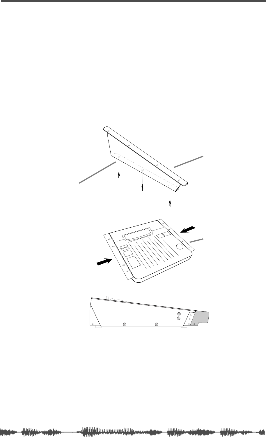
Installing the VM200
Locate the VM200 on a level, stable surface.
You can also mount the VM200 vertically in a rack using the Fostex
9910 optional rack mount adapter. Remove the six screws from the
bottom of the VM200, attach the rack mount adapter, then reinstall
the screws as shown in the illustration below.
Refer to the
Precautions
for information on appropriate locations and
environments for the VM200.
Refer to “Getting Started” on page 43 and “Outputs” on page 107 for
information on connecting the VM200 to other components.
rack-mount adapter
3 screws per side
attach adapters
to sides of mixer
side view of
installed adapter

Introducing the VM200
12
VM200 User’s Guide
Feature Summary
This section summarizes the main features of the VM200.
Audio Specifications
❑
20-bit 64-times oversampling, delta sigma modulation A/D con-
verters
❑
20-bit 128-times oversampling, delta sigma modulation D/A con-
verters
❑
90dB or higher dynamic range
❑
20Hz to 20kHz, +1dB/-3dB frequency response
❑
industry standard 44.1K or 48K sampling rates
Inputs and Outputs
❑
20 Channel Inputs
• Channels 1 - 8: Analog In
• Channels 9-16: ADAT In (20-bit)
• Channels 17-20: Effect Return (for internal effects only)
• Switchable balanced XLR and balanced/unbalanced phone
jacks
• +48V phantom power support for XLR Analog In jacks 1-4
• Route S/P DIF input signals to any of 20 channels
❑
18 Outputs
• Stereo buss output (ST BUSS OUT)
• Recording buss output (REC BUSS OUT)
• 20-bit digital two-channel output (S/P DIF OUT)
• 20-bit digital ADAT eight-channel output (ADAT OUT)
• Two auxiliary outputs (AUX SEND 1-2)
• ADD AUX function adds two auxiliary outs (AUX SENDS 3-4)
• Solo buss outputs post-fader listen (PFL) signals from any chan-
nel or buss to the Monitor or Phones outputs.
❑
MIDI IN, MIDI OUT, and MIDI THRU (built into the mixer)
❑
Word Clock In and Out
❑
Analog two-track input jacks (2TRK IN) enable you to monitor two
tracks without affecting the mix.
❑
4 Insert jacks for external effects returns

Mixer Functions
VM200 User’s Guide
13
Mixer Functions
❑
Scene Memory (up to 100 scenes)
❑
3 Preset Scenes (INIT, RECORDING, MIXDOWN)
❑
60mm continuous motorized faders
❑
Stopless rotary controls
❑
4-band parametric EQ for channels 1-16
❑
Dual internal effects processors
❑
EQ Library with 50 Presets plus 50 memory locations for custom-
ized EQ programs
❑
Effect Library featuring 50 Preset effect programs, and memory
locations for 50 user-customized effect programs
❑
The ADAT DIRECT send function enables you to assign input chan-
nel 1-8 signals to ADAT 1-8 (and turn any channel on or off).
❑
You can pair adjacent (odd-even) input channels.
❑
You can pair AUX SEND 1 and 2, and AUX SEND 3 and 4.
❑
Three Fader groups (A, B, C)
❑
Three Mute groups (A, B, C)
❑
Channel Copy function copies parameter settings, including mute
group and fader group information, from one channel to another
❑
EQ Copy function copies EQ settings from one channel to another.
❑
LED-segment meter displays ST BUSS OUT level
❑
LCD meter displays levels for 20 input channels or 18 output chan-
nels
❑
Two Solo modes, PFL and MIX-SOLO, enable you to monitor signals
pre-fader or post-fader
❑
Large 256x64 dot resolution LCD Display
MIDI functions
❑
You can use Program Change messages to recall scenes (Presets
and User tables)
❑
You can use Control Change messages to control mixer parameters
(Presets and User tables)
❑
You can use System Exclusive messages to control mixer parame-
ters
❑
You can output MIDI Machine Code (MMC) by pressing keys on the
control panel
❑
MIDI Bulk Dump capability for data backup and transfer

Introducing the VM200
14
VM200 User’s Guide
Mixer Configuration
The VM200 is equipped with a total of 20 analog and digital inputs:
eight analog mono input channels (1-8), four internal effects
returns, and an eight-channel ADAT digital input. A two-channel
S/P DIF digital input signal can be routed to any of 20 channels,
and a two-track analog input (2TRK IN) is also provided.
External effects signals can be returned to the VM200 via four
INSERT phone jacks.
Input channels 1 through 8 feature trim control attenuators and TRS
phone jack connectors. Input channels 1 through 4 can also be
switched to +48V phantom-powered balanced XLR-type connectors.
Two effects busses send signals to the two on-board effects proces-
sors. An Effects Library contains 50 high-quality preset effects pro-
grams. The effects can be modified and stored in the Effects Library
for future recall. The VM200 returns the effects signals via channels
17-20.
The VM200 features 18 outputs.
A stereo buss outputs the stereo buss signal; a record buss outputs
the record buss signal.
There are two fixed AUX Sends, and two more can be added through
the use of an ADD AUX function (although the record buss is unavail-
able when the ADD AUX parameter is on).
Digital outputs include a 20-bit digital two-channel output (S/P DIF
OUT), a 20-bit digital ADAT eight-channel output (ADAT OUT).
Monitor and headphone outputs facilitate stereo monitoring via
speakers or headphones.
A four-band parametric equalizer is available for each input channel.
EQ programs can be stored in and recalled from an on-board EQ
Library.
You can cascade multiple VM200s together to increase the number of
input channels.
Why a
Digital
Mixer?
One of the best things about a
digital
audio mixer is that it is able to
combine audio signals from various sources without introducing vir-
tually any signal degradation, distortion, crosstalk, or noise.
Digital recording to tape or hard disk-based systems is increasingly
popular. However, many of these small studios use 4-, 8-, or 16-chan-
nel
analog
mixers.
The VM200 Digital Recording Mixer enables you to keep your audio
signals in the digital domain for both mixing
and
recording, resulting
in new levels clarity and quality in your recordings.

Four-band Parametric EQ & EQ Library
VM200 User’s Guide
15
Four-band Parametric EQ & EQ Library
Channels 1 through 16 feature a four-band parametric equalizer
(EQ), with variable Gain, Frequency, and Q controls.
The LO-MID and HI-MID bands use parametric EQ. The LO band can
function as an HPF, shelving, or parametric EQ; the HI band can func-
tion as an LPF, shelving, or parametric EQ.
An EQ Library can store up to 100 EQ programs for future recall.
Dual On-board Effects Processors
The VM200 features two on-board stereo effects processors, EFF1
and EFF2.
These effects processors utilize Fostex Advanced Signal Processing
Technology (ASP) to create high-quality ambient reverbs, as well as
choruses, delays, flangers, and other effects and combinations.
ASP is an exclusive new digital effect processing technology designed
by Fostex that excels at maximizing the efficiency of digital signal pro-
cessing power. It achieves an overwhelmingly high-density Early
Reflection sound and smooth High Dump response rate via a Har-
monic Feedback Algorithm, and conducts elaborate reverb simulation
using High Density Logarithmic Processing technology, which elimi-
nates mutual interference between integrated delay modules, reduc-
ing audio impurities.
Digital I/O
The VM200 features two types of digital inputs and outputs: S/P DIF
and ADAT.
The S/P DIF is a two-channel digital I/O commonly found on con-
sumer CD players, computer audio cards, etc.
The ADAT IN and ADAT OUT connectors allow a direct eight-channel
connection to any ADAT-compatible digital audio recorder, such as
the Fostex VR800 or the Alesis ADAT series.
About the Display and Graphic User Interface
The LCD display features a resolution of 256-by-64 dots and utilizes
graphic icons to represent faders, send levels, and rotary control
knobs.
The display also provides a graphic EQ response curve and numerical
readouts of mixer parameter settings.
Depending on the lighting in your studio, you may wish to supple-
ment the LCD Display with a gooseneck-type studio lamp or other
light source.

Introducing the VM200
16
VM200 User’s Guide
Scene Memory
The VM200 enables you to store virtually every mixer parameter set-
ting as part of a group snapshot, or “scene,” in the Scene Memory.
The Scene Memory can store up to 100 scenes, which you can later
recall by simply pressing a key on the VM200, or by issuing a remote
MIDI Program Change command from a connected MIDI device.
The Scene Memory store and recall functions let you work on a mix
until you are satisfied, then store virtually all mixer fader and param-
eter settings for instantaneous future recall.
In addition to the scene memory “slots” or “locations” for user pro-
grams, the VM200 features three preset scenes: InitMix, Recording,
and Mix Down, which are designed for optimal performance in com-
mon mixing situations.
MIDI
MIDI connections enable you to take advantage of the VM200’s ver-
satility. MIDI Program Change messages can recall scenes from the
VM200’s Scene Memory. MIDI Control Change messages and Fostex
System Exclusive messages enable real-time parameter control.
To backup and transfer data between VM200s, you can use System
Exclusive Bulk Dump commands.
If a MIDI-compatible recorder is connected to the VM200, you can
control it remotely via MMC (MIDI Machine Control). You can also
cascade VM200s via MIDI connections.
Faders
The VM200 features eight 60mm continuous-throw faders and one
Master fader.
A channel layering system enables you to control up to 20 channels
using only the eight faders and the Master. Page Select keys specify
the “active” channel layer. You can select Channels 1 - 8 Analog In,
Channels 9 - 16 ADAT In, or Channels 17 - 20 Eff Rtn. The LCD Dis-
play will show parameters specific to the selected layer.
The VM200 features seven Fader modes. In each mode, the Faders
function slightly differently, controlling various send and return lev-
els. The Fader modes include: Channel, Eff1, Eff2, Aux1, Aux2, Aux3,
and Aux4.
The motorized faders move automatically when you recall a scene
from Scene Memory, if the Motor parameter is turned on.
The faders can be grouped into one of three groups, enabling you to
control the group with a single fader. Faders for paired channels
move as one.
The faders can function as MIDI controllers if a MIDI device is con-
nected to the VM200 via the MIDI ports.
DIGITAL RECORDING MIXER
VM200
REC BUSS
EFF EDITSELECTED EQ
EQ/HI
EQ/HI-MIDEQ/LO-MID
+10
0
-10
-20
-30
-40
-
+10
0
-10
-20
-30
-40
-
+10
0
-10
-20
-30
-40
-
+10
0
-10
-20
-30
-40
-
+10
0
-10
-20
-30
-40
-
+10
0
-10
-20
-30
-40
-
+10
0
-10
-20
-30
-40
-
GAIN
FREQ
PAN
Q
PAN
ON ON ON ON ON ON ON
SOLO SOLO SOLO SOLO SOLO SOLO SOLO
EQ EDIT EQ EDIT EQ EDIT EQ EDIT EQ EDIT EQ EDIT EQ EDIT EQ EDIT
SOLO
ON ON
SOLO
EQ LIBRARY
STORERECALL
EQ ON
EFF LIBRARY
STORERECALL
EFF2EFF1
RECALLSOLO
EXIT
14
6
13
5
12
4
11
3
2019
FREQ QFREQ Q
Q
GAINGAIN
9-16 ADAT IN 17-20 EFF RTN
P
AGE SELECT
GROUP
PAIR/
METER
CHANNEL/
MIN MAX
+10
0
1
0
1
0
0
-10
-20
-30
-60
-
-40
MMC SEND
PANPANPANPANPANPAN
-40
-36
-24
-18
1212
ST BUSS/SOLO
L R
VM200 User’s Guide
17
CHAPTER 2
Touring the VM200
About This Chapter
This chapter takes you on a guided tour of the VM200, introducing
various components of the control surface, including the faders,
rotary controls, the Data Wheel, and other features.
It also explains the operations associated with each function key.
This chapter then discusses the input and output connectors and
switches on the rear panel and concludes with a block diagram of
the VM200.
Chapter Contents
Top Panel Control Surface . . . . . . . . . . . . . . . . . . . . . . . . . 18
Analog Control Section . . . . . . . . . . . . . . . . . . . . . . . . . . . 19
LCD Display . . . . . . . . . . . . . . . . . . . . . . . . . . . . . . . . . . . . 20
Data Wheel and Neighboring Keys . . . . . . . . . . . . . . . . . . . 21
Function Keys . . . . . . . . . . . . . . . . . . . . . . . . . . . . . . . . . . 22
Setup Section. . . . . . . . . . . . . . . . . . . . . . . . . . . . . . . . . . . 23
Current Scene Status . . . . . . . . . . . . . . . . . . . . . . . . . . . . . 24
Key Mode Section . . . . . . . . . . . . . . . . . . . . . . . . . . . . . . . . 24
Fader Mode Section . . . . . . . . . . . . . . . . . . . . . . . . . . . . . . 27
Selected EQ Section . . . . . . . . . . . . . . . . . . . . . . . . . . . . . . 28
EQ Library . . . . . . . . . . . . . . . . . . . . . . . . . . . . . . . . . . . . . 28
Eff Edit Section . . . . . . . . . . . . . . . . . . . . . . . . . . . . . . . . . 29
Effect Library . . . . . . . . . . . . . . . . . . . . . . . . . . . . . . . . . . . 29
Rec Buss Section . . . . . . . . . . . . . . . . . . . . . . . . . . . . . . . . 30
Scene Memory Section . . . . . . . . . . . . . . . . . . . . . . . . . . . . 31
Channel Control Section. . . . . . . . . . . . . . . . . . . . . . . . . . . 32
Faders . . . . . . . . . . . . . . . . . . . . . . . . . . . . . . . . . . . . . . . . 32
EQ Section Rotary Controls . . . . . . . . . . . . . . . . . . . . . . . . 36
Rear Panel . . . . . . . . . . . . . . . . . . . . . . . . . . . . . . . . . . . . . 38
Block Diagram . . . . . . . . . . . . . . . . . . . . . . . . . . . . . . . . . . 41
Touring the VM200
18
VM200 UserÕs Guide
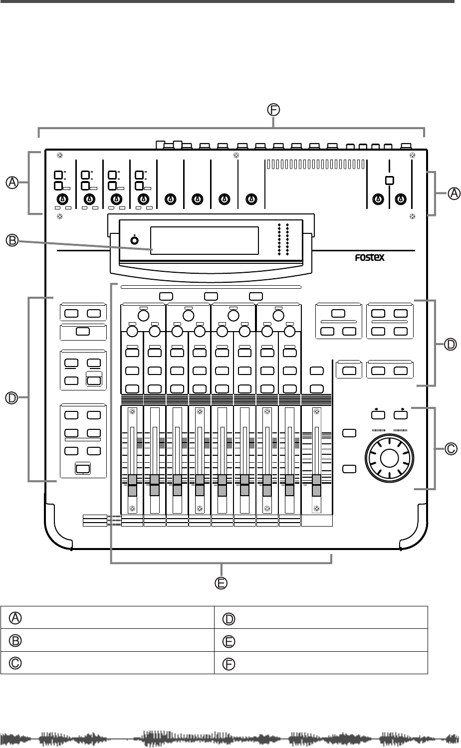
Top Panel Control Surface
The following illustration shows the top panel control surface of the
VM200.
Each section of the mixer is discussed in the following pages.
Analog Control Section (page 19) Function Keys (page 22)
LCD Display (page 20) Input Channel Control Section (page 32)
Data Wheel and Neighboring Keys (page 21) Rear Panel (page 38)
INPUT 4INPUT 3INPUT 2INPUT 1
PAD
26dB
A
B
PAD
26dB
A
B
PAD
26dB
A
B
PAD
26dB
A
B
-16 -60
+10 -34
-16 -60
+10 -34
-16 -60 -16 -60
TRIMTRIMTRIMTRIM
DIGITAL RECORDING MIXER
VM200
SCENE MEMORYREC BUSS
EFF EDITSELECTED EQ
EQ/HI
EQ/HI-MIDEQ/LO-MIDEQ/LOSETUP
CURRENT SCENE STATUS
KEY MODE
+10
0
-10
-20
-30
-40
-
+10
0
-10
-20
-30
-40
-
+10
0
-10
-20
-30
-40
-
+10
0
-10
-20
-30
-40
-
+10
0
-10
-20
-30
-40
-
+10
0
-10
-20
-30
-40
-
+10
0
-10
-20
-30
-40
-
16
8
GAIN
FREQ
PAN
Q
PAN
ON ON ON ON ON ON ON
SOLO SOLO SOLO SOLO SOLO SOLO SOLO
EQ EDIT EQ EDIT EQ EDIT EQ EDIT EQ EDIT EQ EDIT EQ EDIT EQ EDIT
SOLO
ON ON
SOLO
EQ LIBRARY
STORERECALL
EQ ON
EFF LIBRARY
STORERECALL
EFF2EFF1
STORERECALLSOLO
+1/ /-1
DATA
EXIT
ENTER
MASTER
15
7
14
6
13
5
12
4
11
3
10
2
9
1
2019
18
17
FREQ QFREQ Q
FREQ Q
GAINGAINGAIN
1-8 ANALOG IN 9-16 ADAT IN 17-20 EFF RTN
PAGE SELECT
SYSTEM MIDI
PHASE GROUP
ROUTING/ PAIR/
CH VIEW METER
CHANNEL/
AUX1
FADER MODE
AUX2
AUX3 AUX4
EFF1 EFF2
CHANNEL
ADD.AUX
TRIM
-10 -50
TRIM TRIM TRIM
-10 -50 -10 -50 -10 -50
INPUT 5 INPUT 6 INPUT 7 INPUT 8
MIN MAX
GAIN
MAXMIN
GAIN
2TRK IN
PHONESMONITOR
+10
0
-10
-20
-30
-40
-
EFF RTN
ADAT IN
ANALOG IN
0
-10
-20
-30
-60
-
-40
MMC SEND
PANPANPANPANPANPAN
-48
-36
-24
-18
-12
-9
-6
-3
OL
ST BUSS/SOLO
LR
METER
+10 -34 +10 -34
Analog Control Section
VM200 User’s Guide
19
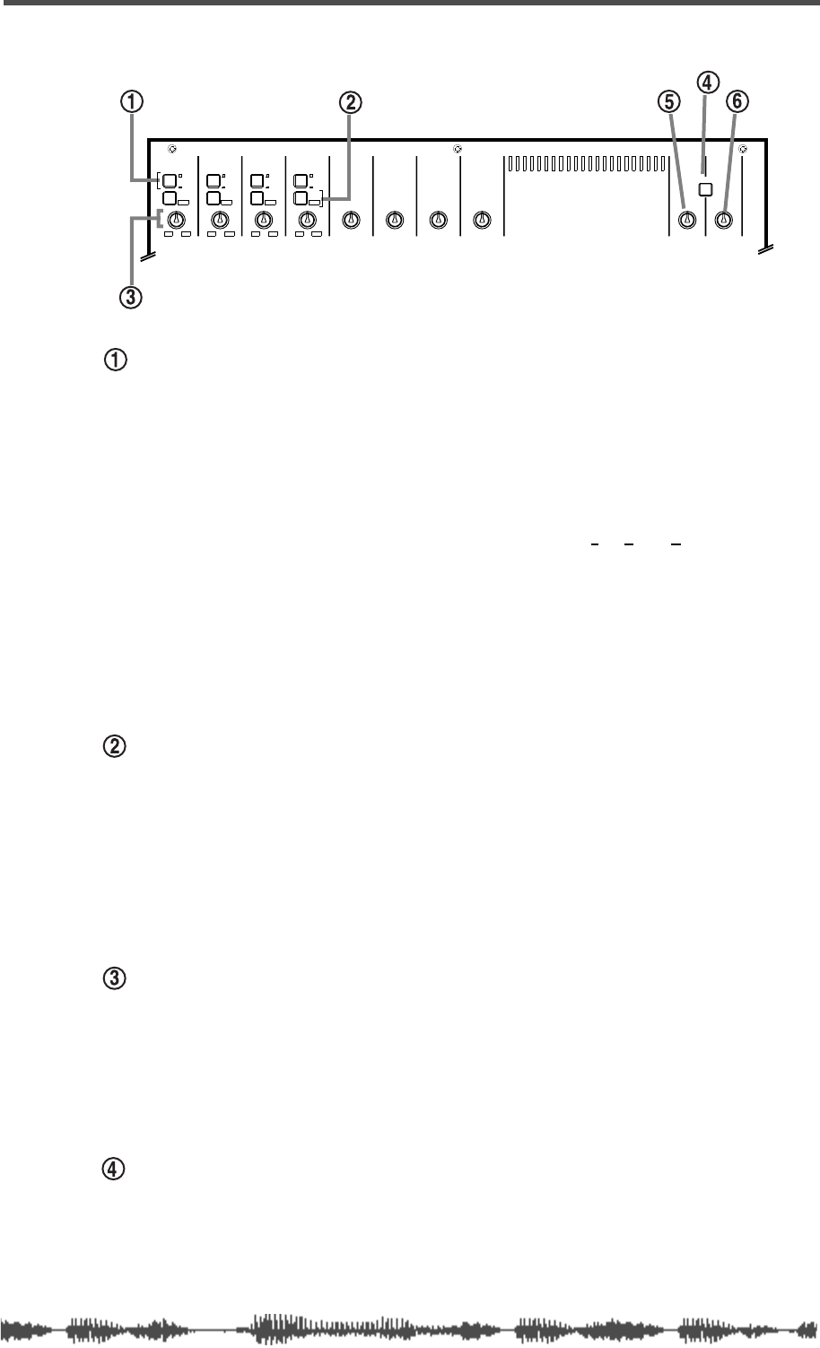
Analog Control Section
A/B Input selectors
The VM200 features four A/B Input selectors that enable you to
select the A or B inputs for input channels 1 through 4.
The A Inputs are balanced XLR-type connectors for use with micro-
phones that feature XLR-type plugs, such as condenser microphones,
or other input devices that require XLR connectors.
The B Inputs are balanced/unbalanced TRS (tip-ring-sleeve) phone
connectors, for use with dynamic microphones and other sound
sources that require phone jacks. (These connectors will accept bal-
anced or unbalanced inputs.)
For more information, see “Input Channels 1–4” on page 60.
The A Inputs are selected by default (the selector is not depressed).
Press the A/B Input Selector to select the B input.
PAD (26dB) switches
The four Pad switches turn the 26 dB input pads on and off for input
channels 1–4.
When turned on, the input pads attenuate the signal by 26 dB. This
helps the preamp handle “hot” signals.
For more information, see “Pad Switches (Input channels 1–4)” on
page 63.
TRIM controls
The four Trim controls (1–4) attenuate the gain of the input preamps
in the range of +10 to -34 or -16 to -60 dB, depending on whether or
not the signal is attenuated by the Pad 26dB switch. The other four
Trim controls (5–8) attenuate the gain of the input preamps in the
range of -10 to -50.
2TRK IN switch
The 2TRK IN switch enables you to monitor the signal input to the
2TRK IN connector on the rear panel. You can monitor this signal
through MONITOR OUT or PHONES OUT. The signal is unaffected by
mixer settings.
INPUT 4INPUT 3INPUT 2INPUT 1
PAD
26dB
A
B
PAD
26dB
A
B
PAD
26dB
A
B
PAD
26dB
A
B
-16 -60
+10 -34
-16 -60
+10 -34
-16 -60 -16 -60
TRIMTRIMTRIMTRIM TRIM
-10 -50
TRIM TRIM TRIM
-10 -50 -10 -50 -10 -50
INPUT 5 INPUT 6 INPUT 7 INPUT 8
MIN MAX
GAIN
MAXMIN
GAIN
2TRK IN
PHONESMONITOR
+10 -34 +10 -34
Touring the VM200
20
VM200 User’s Guide
Monitor Gain knob
Use the Monitor Gain knob to adjust the Monitor Out level.
The Monitor Out jacks output the buss signal you specify on the
SETUP SYSTEM 1:CLOCK/MON
function page. (The default is ST BUSS
OUT.)
Phones Gain knob
Use the Phones Gain knob to adjust the headphone output level.
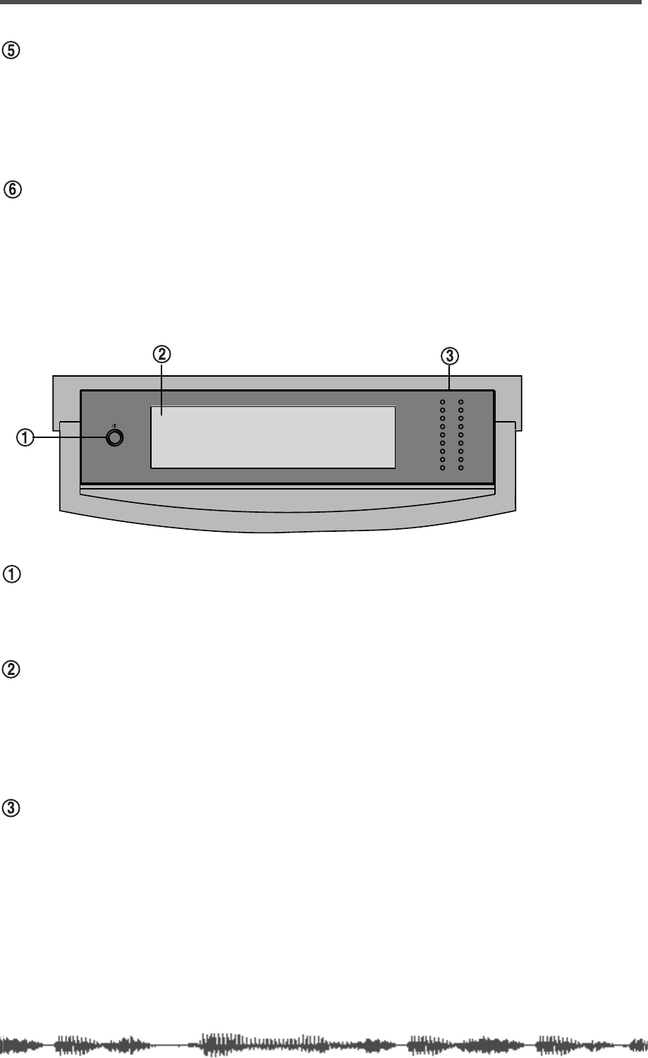
LCD Display
Contrast dial
Rotate this dial left or right to adjust the contrast of the LCD Display
for maximum clarity.
LCD Display
The LCD Display has a resolution of 256 x 64 dots. It displays various
parameters and numerical values, and uses graphic icons to repre-
sent faders, rotary controls, pan positions, and switches.
For more information, see “Reading the Display” on page 49.
Meters
The LCD Display features meters for 20 input channels or 18 output
channels.
To the right of the LCD Display is a pair of nine-segment LED meters
for the Left and Right channels of the stereo buss signals.
-36
-24
-18
-12
-9
-6
-3
OL
ST BUSS/SOLO
LR
METER
-48
Data Wheel and Neighboring Keys
VM200 User’s Guide
21
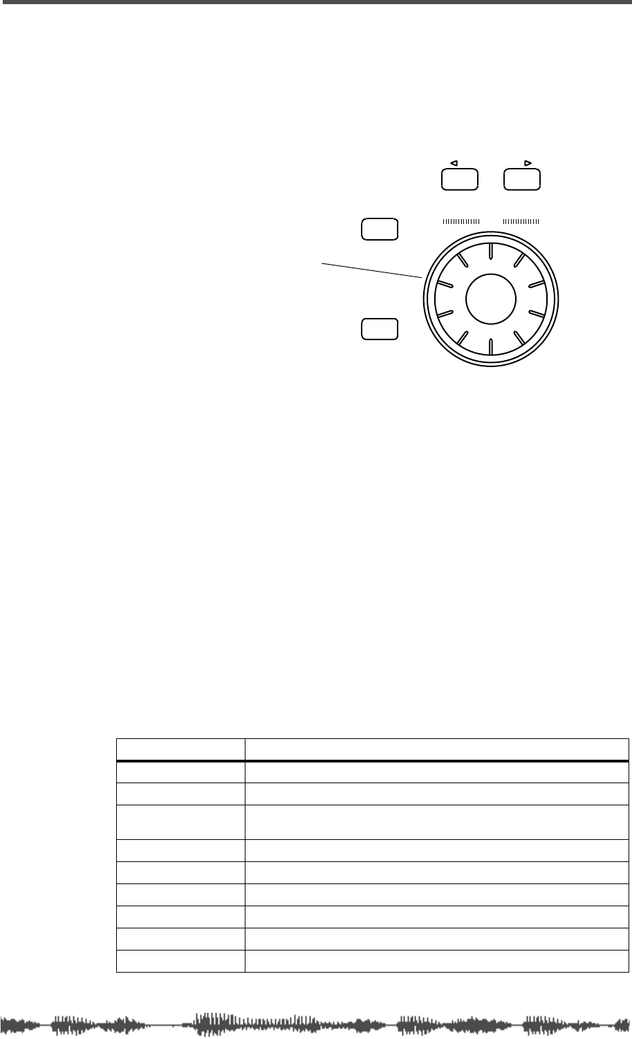
Data Wheel and Neighboring Keys
The Data Wheel is located in the lower-right corner of the VM200.
It enables you to scroll through lists of programs in the Effect and EQ
Libraries. You can also use the Data Wheel to move the cursor left and
right when naming a new effect or EQ program.
[</-1] and [+1/>] Keys
These keys can step through scrollable lists, such as the Effect
Library or EQ Library.
[ENTER] and [EXIT] Keys
You can use the
[ENTER]
key to execute certain functions, such as
confirming new parameter values, writing to memory, or initializing
the VM200. You can also use it to confirm new parameter settings.
In many cases, if you hold down the
[ENTER]
key while pressing
another key, the VM200 displays the key’s first function page (as
opposed to the most recently-displayed function page for that key).
Pressing the
[EXIT]
key usually exits the current operating mode and
displays the
CHANNEL EDIT
function page.
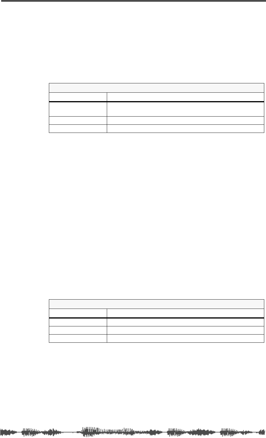
The following table shows additional
[ENTER]
key functions.
Press ENTER and... Operation
ON
Sets channel fader parameter in selected fader mode to Unity Gain.
Rotary Controls
Increases adjustment increment in EFF Edit or EQ Edit mode.
EQ EDIT
VM200 enters EQ Edit mode. (If already in EQ Edit mode, the
parameter being edited will be initialized after confirmation.
SYSTEM
Displays the first SYSTEM function page.
MIDI
Displays the first MIDI function page.
CH VIEW
Displays the first CH VIEW function page.
PAIR/GROUP
Displays the first PAIR/GROUP function page.
ROUTING/PHASE
Displays the first ROUTING/PHASE function page.
CHANNEL/METER
Displays the first CHANNEL/METER function page.
+1/ /-1
DATA
EXIT
ENTER
Use your thumb or finger
to rotate the Data Wheel
Touring the VM200
22
VM200 User’s Guide
Function Keys
This section provides a brief tour of the VM200’s numerous function
keys.
When you press certain function keys, such as
[SYSTEM]
or
[CURRENT
SCENE STATUS]
, the VM200 displays a “function page” of information
on the LCD Display Panel. Each function page contains parameters
that you can set to configure and control the VM200.
In many cases, repeatedly pressing a function key displays additional
pages of parameters. The sequence of pages cycles around to begin
again (i.e., page 1, 2, 3, 1, 2, 3...)
Other function keys, such as EFF1 in the Fader Mode section, do not
directly display information on the LCD Display Panel, but neverthe-
less configure or control the VM200 in other ways.
Some function keys are opaque grey. Others are translucent and
fixed above an LED light that can light up or flash to indicate status
information.
In general, the translucent function keys flash to indicate that they
are available for selection. Once selected, they remain lit.
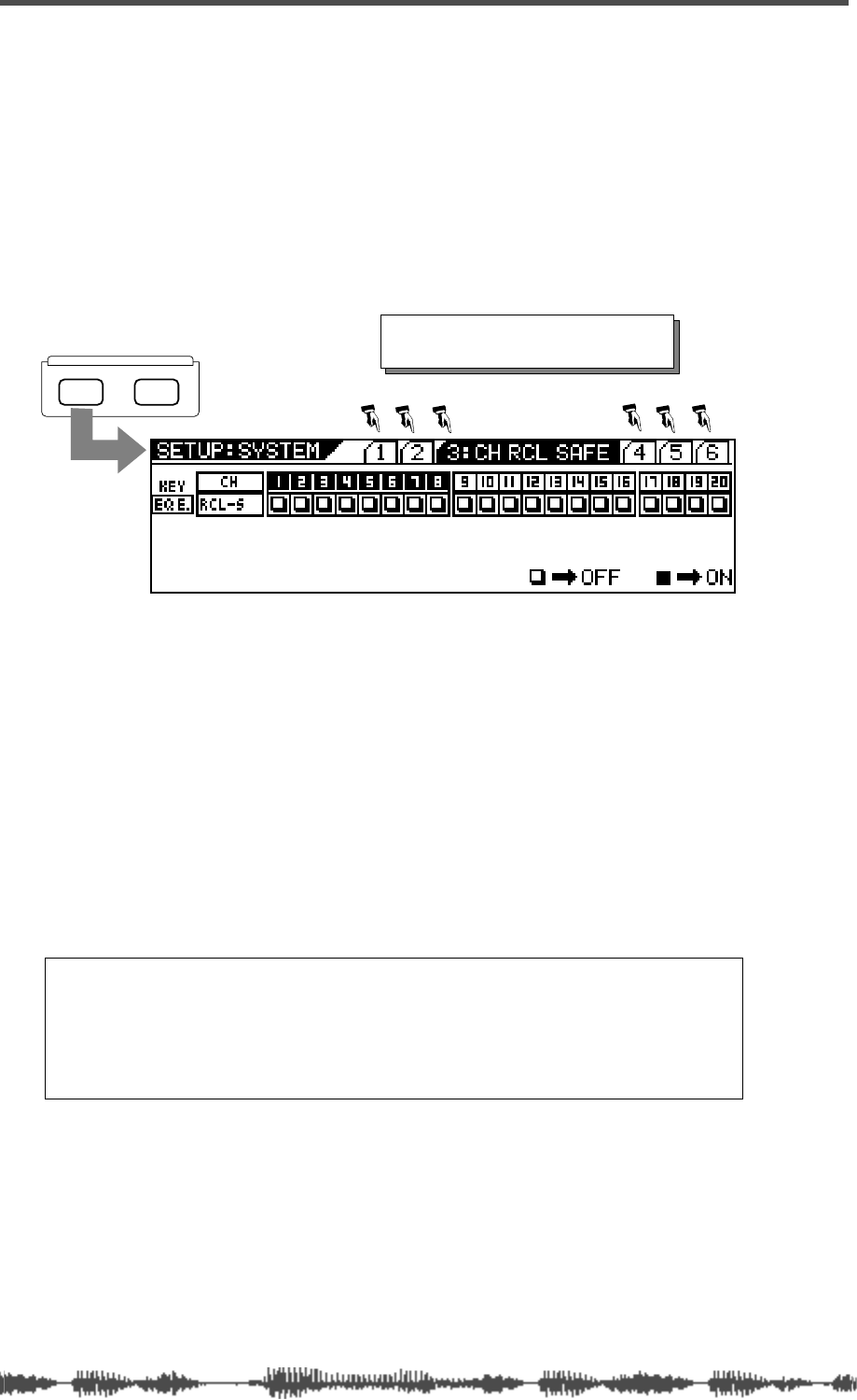
SETUP
SYSTEM MIDI
Each time you press the [SYSTEM] key,
a subsequent function page is displayed.
Note: The procedures in this manual offer specific steps that you
can follow to accomplish certain tasks. Phrases such as “press
the function key twice” assume the function page cycle always
begins with the first function page. This may not always be the
case. If not, simply press the key repeatedly until the desired page
appears.
Setup Section
VM200 User’s Guide
23
Setup Section
The Setup section features two function keys: [
SYSTEM]
and [MIDI].
The SYSTEM key displays function pages that enable you to configure
the VM200.
The [MIDI] key displays function pages that enable you to interface
the VM200 to MIDI devices.
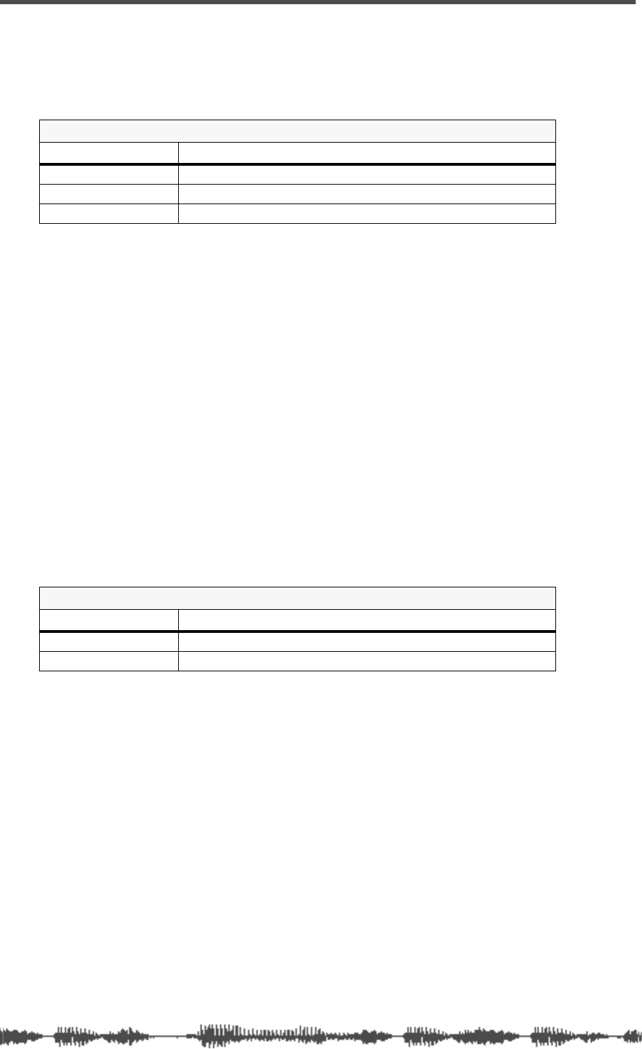
[SYSTEM] Key
The [
SYSTEM]
key enables you to configure the VM200.
It displays a sequence of six function pages on the LCD Display if you
repeatedly press the key.
[MIDI] Key
The
[MIDI]
key enables you to interface the VM200 with MIDI (Musical
Instrument Digital Interface) instruments and devices.
The
[MIDI]
key also features six function pages, as summarized below:
SYSTEM Key
Function Pages Includes parameters that enable you to...
1:CLOCK/MON Select a system clock, specify the buss to monitor, select a
solo mode and key operation, turn the fader motors on or
off, and set the Frame mode.
2:RCL SAFE Specify parameters that you want to remain unmodified
(not updated) when you recall a scene from memory.
3:CH RCL SAFE Specify channels that you want to remain unmodified (not
updated) when you recall a scene from memory.
4:SOLO SAFE Specify channels that you want to send to the ST Buss in
M-Solo mode.
5:POWER ON RCL Specify which scene the mixer should recall from memory
when you power on the VM200.
6:INITIALIZE Re-initialize the VM200, resetting all parameters to factory
default settings.
MIDI Key
Function Pages Includes parameters that enable you to...
1:MIDI TX&RX Set MIDI transmit/receive channels, set MIDI message trans-
mission and reception on or off.
2:PGM TABLE1 Edit User Program Change Assign table 1.
3:PGM TABLE2 View Program Change Assign table 2.
4:CTL TABLE1 Edit User Control Change Assign table 1.
5:CTL TABLE2 View Control Change Assign table 2.
6:BULK DUMP Set up Bulk Dump transmission.
SETUP
SYSTEM MIDI
Touring the VM200
24
VM200 User’s Guide
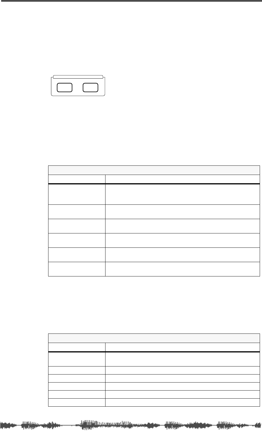
Current Scene Status
The Current Scene Status section features only one key, which
shares its name.
When you press the
[CURRENT SCENE STATUS]
key, the VM200 enters
Current Scene Status mode and displays the
CURRENT SCENE STATUS
function page. The number and name of the scene (e.g.,
01:MY_SCENE
) appear in the top right of the display.
The
CURRENT SCENE STATUS
function page enables you to:
• Enable the EQ for channels 1-8, 9-16, or 1-16
• Turn on the ADD. AUX parameter (to enable AUX Sends 3&4)
• Set the Smoothing function to Level 1 or 2
• Set the record buss gain (REC-B.GAIN) from [
∞
to -90 to 0dB]
(available when ADD. AUX is off)
• Set the sends for AUX1, AUX2, AUX3, and AUX4, EFF1, and EFF2
to Pre-fader or Post-fader
• Pair AUX Sends (Aux1&2 or Aux3&4).
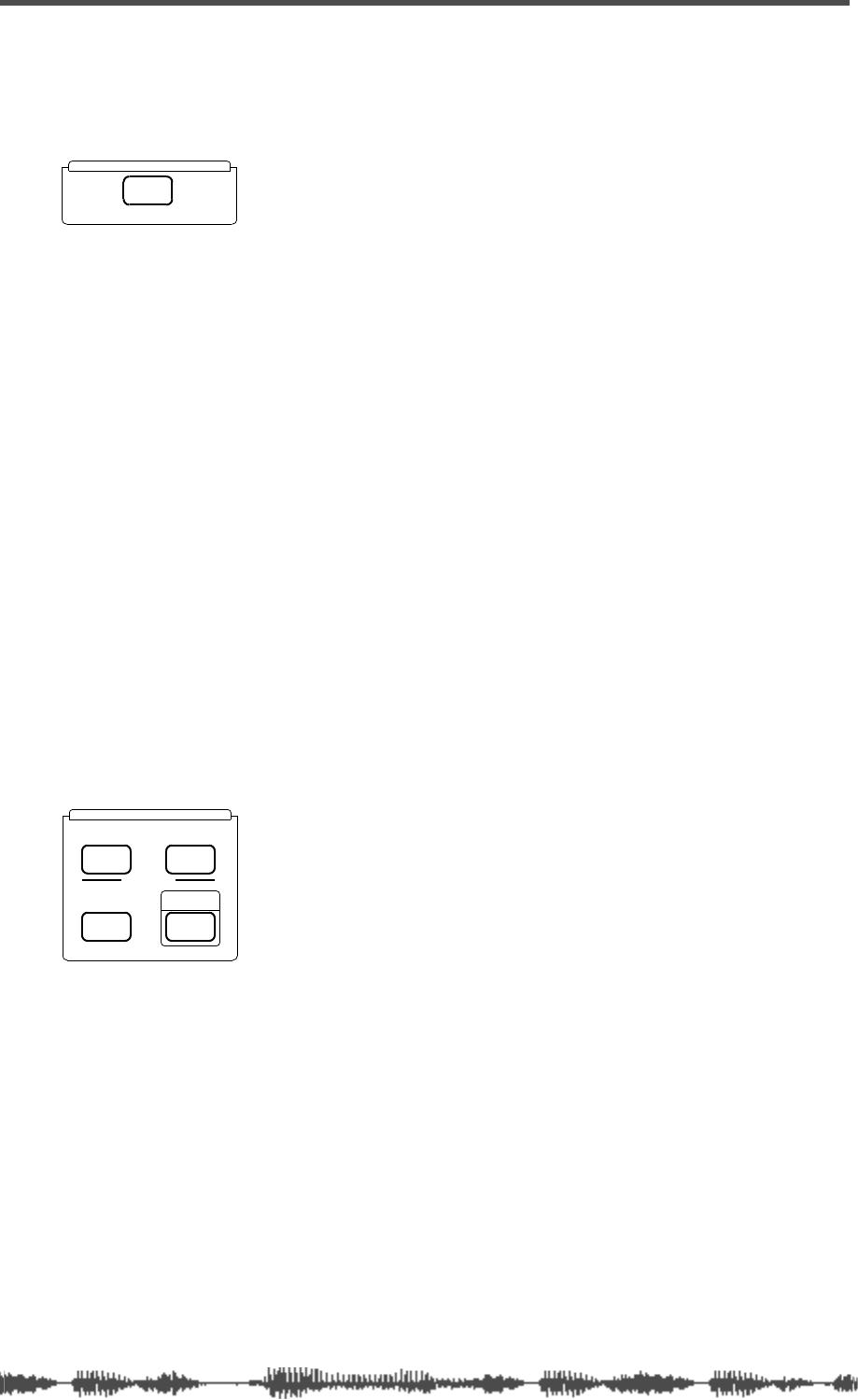
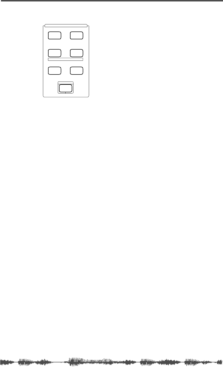
Key Mode Section
The Key Mode section features four function keys:
[ROUT-
ING/PHASE]
,
[PAIR/GROUP]
,
[CH VIEW]
, and
[CHANNEL/METER]
, as
described below.
[ROUTING/PHASE] Key
The
[ROUTING/PHASE]
key displays a sequence of three function
pages that let you control mixer routing, assign S/P DIF inputs to
channels, and invert the phase for each channel.
The
ROUTING
function page lets you route input channels 1–20 to the
Stereo Buss (ST BUS), the Record Buss (REC BUS), or the ADAT out-
put (DIRECT).
Press a Page Select key to specify Channels 1-8, 9-16, or 17-20. Then
press the
[EQ EDIT]
,
[SOLO]
, and/or
[ON]
key for each channel to route
the signal to a potential destination. The indicator in the chan-
nel/buss matrix highlights (dark square).
CURRENT SCENE STATUS
KEY MODE
PHASE GROUP
ROUTING/ PAIR/
CH VIEW METER
CHANNEL/
MMC SEND
[PAIR/GROUP] Key
VM200 User’s Guide
25
The
S/P DIF
function page lets you assign the S/P DIF digital two-track
input to any odd-even pair of channels (e.g., 1&2, 13&14, etc.).
The
Ø PHASE
function page lets you invert the phase for each of input
channels 1 through 20.
Press a Page Select key to specify Channels 1-8, 9-16, or 17-20.
You can also use the
[ROUTING/PHASE]
key in conjunction with the
[PAIR/GROUP]
key to enter MMC mode. (For more information, see
“MMC (MIDI Machine Control) Send” on page 192.)
[PAIR/GROUP] Key
The
[PAIR/GROUP]
key displays a sequence of three function pages
that enable you to pair channels, mute groups of channels, or group
faders under the control of a single fader.
The
CHANNEL PAIR (CH PAIR)
function page enables you to pair any two
odd-even channels using the
[EQ EDIT]
keys.
The
MUTE GROUP
function page enables you to create three groups of
channels (Mute Groups A, B, and C) that you can silence instantly.
The
FADER GROUP
function page also enables you to create three groups
of channels (Fader Groups A, B, and C). Faders in a group can be con-
trolled by a single fader.
Use the Page Select keys to specify Channels 1-8, 9-16, or 17-20; use
the
[EQ EDIT]
,
[SOLO]
, and
[ON]
keys to apply these functions to spe-
cific channels.
You can also press the
[ROUTING/PHASE]
key simultaneously with the
[PAIR/GROUP]
key to enter MMC mode. (For more information, see
“MMC (MIDI Machine Control) Send” on page 192.)
[CH VIEW] Key
The Channel View
[CH VIEW]
key displays a sequence of three func-
tion pages that display settings for specific channels, and allow you
to copy channel and EQ settings from a source channel to destina-
tion channels.
The
CH VIEW
function page lets you view (but not modify) settings for
specific channels.
ROUTING/PHASE Key
Function Pages Includes parameters that enable you to...
1:ROUTING Route input channels 1-20 to ST BUSS, REC BUSS, or ADAT
DIRECT.
2:S/P DIF Assign S/P DIF digital input to any odd-even channel pair.
3:Ø PHASE Invert phase for each input channel.
PAIR/GROUP Key
Function Pages Includes parameters that enable you to...
1:CH PAIR Pair odd-even input channels.
2:MUTE GROUP Create Mute Groups A, B, C
3:FADER GROUP Create Fader Groups A, B, C
Touring the VM200
26
VM200 User’s Guide
The
CH COPY
function page lets you copy channel settings from a
source channel to one or more destination channels.
The
EQ COPY
function page lets you copy EQ settings from a source
channel to one or more destination channels.
[CHANNEL/METER] Key
Pressing the
[CHANNEL/METER]
key displays two
CHANNEL EDIT
func-
tion pages: Channel Edit/Input and Channel Edit/Output.
These are essentially the “main” pages of the VM200, the pages you
will likely display most often. However, unlike other function pages,
the name of the page does not appear on a
CHANNEL EDIT
function
page.
The name and number of the Current Scene appear in the top-left
corner of the display.
These function pages enable you to view and set the pan position for
each channel.
You can also view the
input
levels for input channels 1-20.
Pressing the
[CHANNEL/METER]
key a second time displays the
output
levels for the ADAT, AUX, Effects, Record Buss, and Stereo Buss out-
puts.
CH VIEW Key
Function Pages Includes parameters that enable you to...
1:CH VIEW View channel parameter settings.
2:CH COPY Copy channel settings to other channels.
3:EQ COPY Copy EQ settings to other channels.
CHANNEL/METER Key
Function Pages Includes parameters that enable you to...
1:CH EDIT (Input) View input levels and set pan positions.
2:CH EDIT (Output) View output levels and set pan positions.
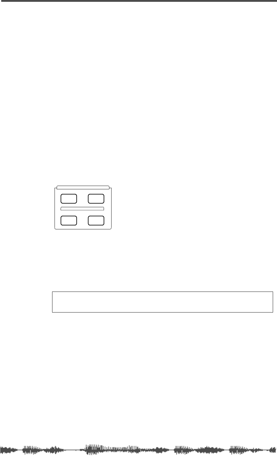
Fader Mode Section
VM200 User’s Guide
27
Fader Mode Section
The VM200 features 20 input channels and 18 output channels.
However, with only eight faders plus the Master fader, the VM200
must use its faders for multiple tasks to accommodate all those
channels.
Depending on the Fader Mode, the faders (as well as the
[ON]
,
[SOLO]
,
and
[EQ EDIT]
keys) control different functions. You determine which
functions the faders and keys will control by selecting a Fader Mode.
[AUX1], [AUX2], [AUX3], and [AUX4] Keys
If you press one of these function keys, the faders, the Master fader,
[ON]
and
[SOLO]
keys control the AUX send signals. (To enable AUX3
and AUX4 keys, turn on the ADD. AUX parameter on the
CURRENT
SCENE STATUS
function page. For more information, see “Enabling AUX
Sends 3 & 4 (ADD. AUX Parameter)” on page 115.)
[EFF1] and [EFF2] Keys
If you press one of these function keys, the faders, the Master fader,
[ON]
and
[SOLO]
keys control the EFF1 and EFF2 send signals.
[CHANNEL] Key
The
[CHANNEL]
key is something like a “Home” key. With this key
selected, channel controls handle input channel signals and the Mas-
ter controls handle stereo out signals.
AUX1
FADER MODE
AUX2
AUX3 AUX4
EFF1 EFF2
CHANNEL
ADD.AUX

Touring the VM200
28
VM200 User’s Guide
Selected EQ Section
An equalizer (EQ) enables you to boost or cut specific frequency
ranges to “shape” a sound.
The VM200 features a four-band parametric equalizer for each input
channel. Each band features rotary controls for Gain, Frequency,
and Q.
The LO-MID and HI-MID bands use parametric EQ. The LO band can
function as an HPF, shelving, or parametric EQ; the HI band can
function as an LPF, shelving, or parametric EQ.
The Selected EQ section features three keys: an
[EQ ON] key, and
[STORE] and [RECALL] keys for the EQ Library.
For more information on using the EQ, see EQ on page 75.
[EQ ON] Key
The [EQ ON] key enables you to turn on or bypass the equalization
parameters selected via the [EQ EDIT] keys.
EQ Library
The EQ Library stores sets of equalization parameters as EQ pro-
grams that you can later recall.
The EQ Library features 50 preset EQ programs. You can store up to
50 new EQ programs (in EQ Library locations 50 - 99).
[RECALL] Key
Pressing the [RECALL] key displays the EQ LIBRARY RECALL function
page, which enables you to select from up to 100 equalization pro-
grams (00 - 99).
Use the Data Wheel or [</-1] and [+1/>] keys to scroll through the list,
and press the [ENTER] key to recall the selected EQ program.
The lower half of the function page displays the pan and fader set-
tings for each channel.
[STORE] Key
The [STORE] key enables you to create and store new EQ programs.
Once you’ve worked on a mix, adjusting the Gain, Frequency, and Q
parameters to your satisfaction for all four bands of each channel,
SELECTED EQ
EQ LIBRARY
STORERECALL
EQ ON
Eff Edit Section
VM200 User’s Guide 29
you may wish to store the EQ settings for future recall.
Pressing the [STORE] key displays the EQ LIBRARY STORE function page.
Use the Data Wheel to scroll through the list to select the location
(program number) where you want to store the new EQ program.
Press the [ENTER] key to display the EQ LIBRARY NAME EDIT function
page, then name the EQ program.
Pressing the [ENTER] key again stores the program in the EQ Library
for future recall.
One way to create a new EQ program is to select the EQ program most
similar to your “target” EQ, then modify various parameters to sculpt
the response curve into shape.
For more information, see “Storing EQ Programs” on page 86.
Eff Edit Section
The Eff Edit section features four keys: [EFF1], [EFF2], and [STORE]
and [RECALL] keys for the Effect Library.
[EFF1] and [EFF2] Keys
The [EFF1] and [EFF2] keys in the Eff Edit Section enable you to select
for editing the effect that is currently loaded in effect processor 1 or 2.
Pressing [EFF1] or [EFF2] displays an EFF EDIT function page that
includes parameters related to the current effect.
For example, a Large Hall Reverb effect includes parameters for
Reverb Time, E/R Balance, HPF, LPF, Initial Delay, PreDelay, Room
Size, etc. The 3D Chorus effect includes parameters for Depth, HPF,
and LPF.
Effect Library
The Effect Library stores effects that you can recall.
It features 50 preset effects and effect combinations. You can modify
the parameters for these existing effects to create and store an addi-
tional 50 custom effect programs.
EFF EDIT
EFF LIBRARY
STORERECALL
EFF2EFF1
Note: Do not confuse these keys with the keys in the Fader Mode
section of the same name.

Touring the VM200
30 VM200 User’s Guide
[RECALL] Key
Pressing the [RECALL] key displays the EFFECT LIBRARY RECALL function
page, which enables you to select from 50 preset effects programs
(00 - 49).
Use the Data Wheel or [</-1] and [+1/>] keys to scroll through the list
or to select a program. Press the [ENTER] key to recall the Effect pro-
gram.
[STORE] Key
The [STORE] key enables you to store your own Effect programs in
one of 50 user program locations (program numbers 50 -99).
Once you’ve edited effect parameters to your satisfaction, you may
wish to store them for future recall.
Press the [STORE] key to display the EFFECT LIBRARY STORE function
page.
Use the Data Wheel or [</-1] and [+1/>] keys to scroll through the list
to select the location (50–99) where you want to store the new effect
program.
Press the [ENTER] key to display the EFFECT LIBRARY NAME EDIT function
page, then name the effect program.
Pressing the [ENTER] key again stores the program in the Effect
Library for future recall.
One way to create a new Effect program is to select the Effect program
most similar to your “target” effect, then modify various parameters
to sculpt the effect into shape.
For more information, see “Effects” on page 123.
Rec Buss Section
The Rec Buss section features only the [SOLO] function key.
The VM200 also features [SOLO] keys for each channel and the Mas-
ter fader. For more information on the Rec Buss [SOLO] keys, see
“Soloing the REC BUSS OUT” on page 113.
The REC BUSS is enabled only when the ADD. AUX parameter is
turned off. For more information, see “Enabling AUX Sends 3 & 4
(ADD. AUX Parameter)” on page 115.

[SOLO] Key
VM200 User’s Guide 31
[SOLO] Key
The [SOLO] key in the Rec Buss section enables you to solo the
Record Buss.
Scene Memory Section
The Scene Memory section includes [RECALL] and [STORE] keys that
enable you to recall scenes from memory and store new scenes to
memory.
A “scene” is a collection or “snapshot” of virtually all the parameter
settings of the VM200 at a given point in time.
[RECALL] Key
Pressing the [RECALL] key displays the SCENE MEMORY RECALL function
page.
You can use the Data Wheel or [</-1] and [+1/>] keys to scroll
through the list of stored and preset scenes.
Press the [RECALL] key again to recall the scene from memory and
remain in Scene Memory mode, or press the [ENTER] key to recall the
scene and exit Scene Memory mode.
[STORE] Key
The [STORE] key enables you to store scenes in Scene Memory.
Pressing the [STORE] key displays the SCENE MEMORY STORE function
page.
Press the [ENTER] key to display the SCENE MEMORY NAME EDIT function
page, then name the new Scene Memory. Press the [ENTER] key again
to store the scene in memory.
REC BUSS
SOLO
SCENE MEMORY
STORERECALL
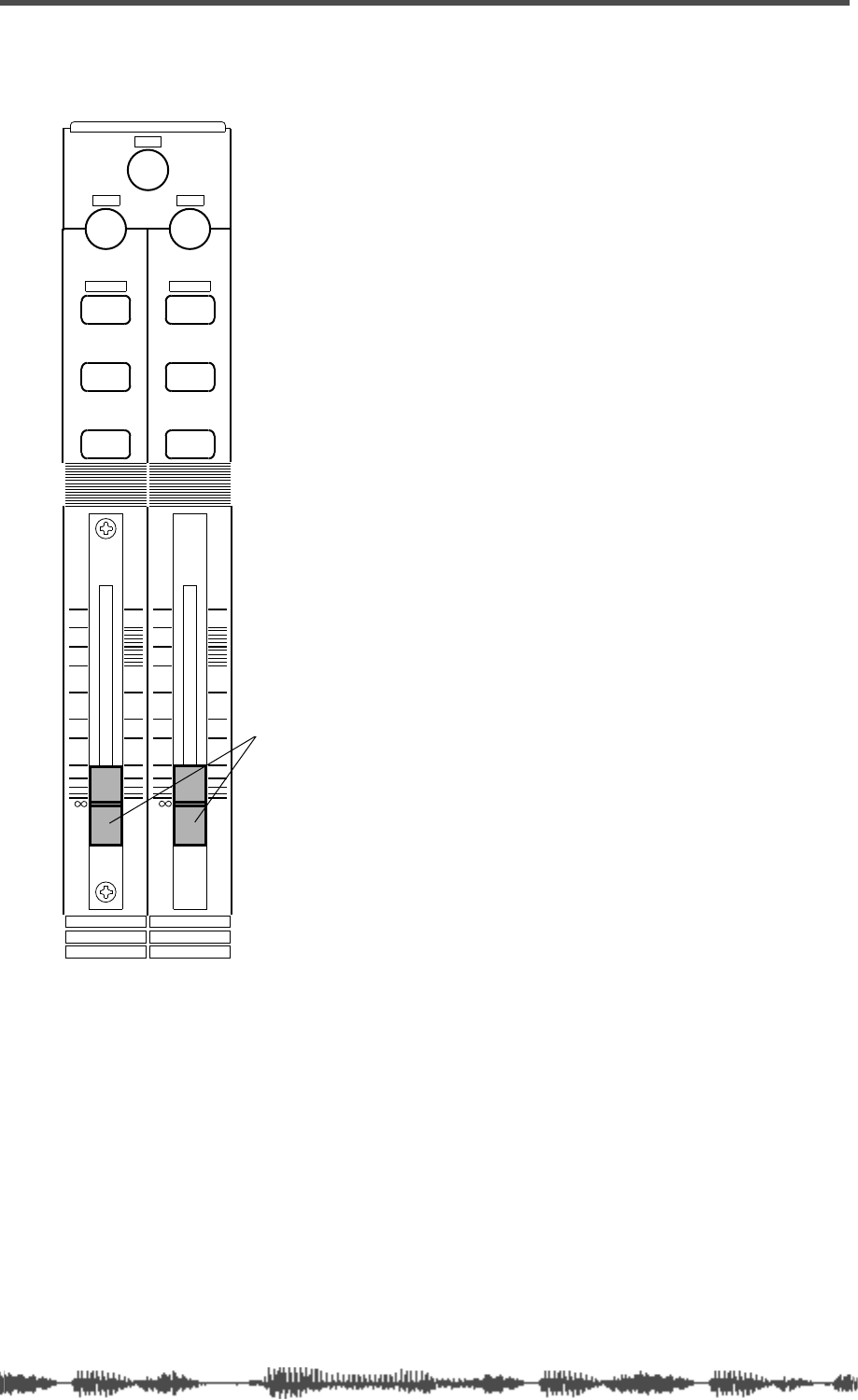
Touring the VM200
32 VM200 User’s Guide
Channel Control Section
The VM200 features nine 60mm motorized
faders.
Faders 1 through 8 are associated with
separate [ON], [SOLO], and [EQ EDIT] keys.
(The Master fader features only [ON] and
[SOLO] keys.)
Faders 1 - 8 and [ON], [SOLO], and [EQ EDIT]
keys 1-8 typically control channels 1
through 8. However, they can also control
channels 9 through 16, and 17 through 20,
depending on the channel layer you select
using the Page Select keys. (See the “Fader
function” table below.)
The ninth fader is the Master Fader.
Faders 1 - 8 and [ON], [SOLO], and [EQ EDIT]
keys also assign values to various function
page parameters.
You can also use the faders and [ON],
[SOLO], and [EQ EDIT] keys as MIDI control-
lers by setting parameters on the Control
Table function pages, which are displayed
by the Setup [MIDI] function key.
Faders
The faders control different functions
depending on the Fader Mode you select.
You select a Fader Mode by pressing one of
the keys in the Fader Mode section of the
control surface. The VM200 features seven
fader modes: Channel, Aux 1, Aux2, Aux3,
Aux4, Eff1, and Eff2. (For more informa-
tion, see “[ON], [SOLO], & [EQ EDIT] Keys”
on page 34.)
Faders 1 - 8 typically control the channel
gain; the Master Fader typically controls
the Stereo Buss Master gain.
However, in Fader Mode Aux1 for example,
Fader 1 controls the channel-to-Aux1 Send
gain. In Fader Mode Eff2, Fader 1 controls
the channel-to-Eff2 Send gain, and so on.
EQ/LO
+10
0
-10
-20
-30
-40
-
ON ON
SOLO SOLO
EQ EDIT EQ EDIT
10
2
9
1
18
17
FREQ Q
GAIN
+10
0
-10
-20
-30
-40
-
PANPAN
Faders
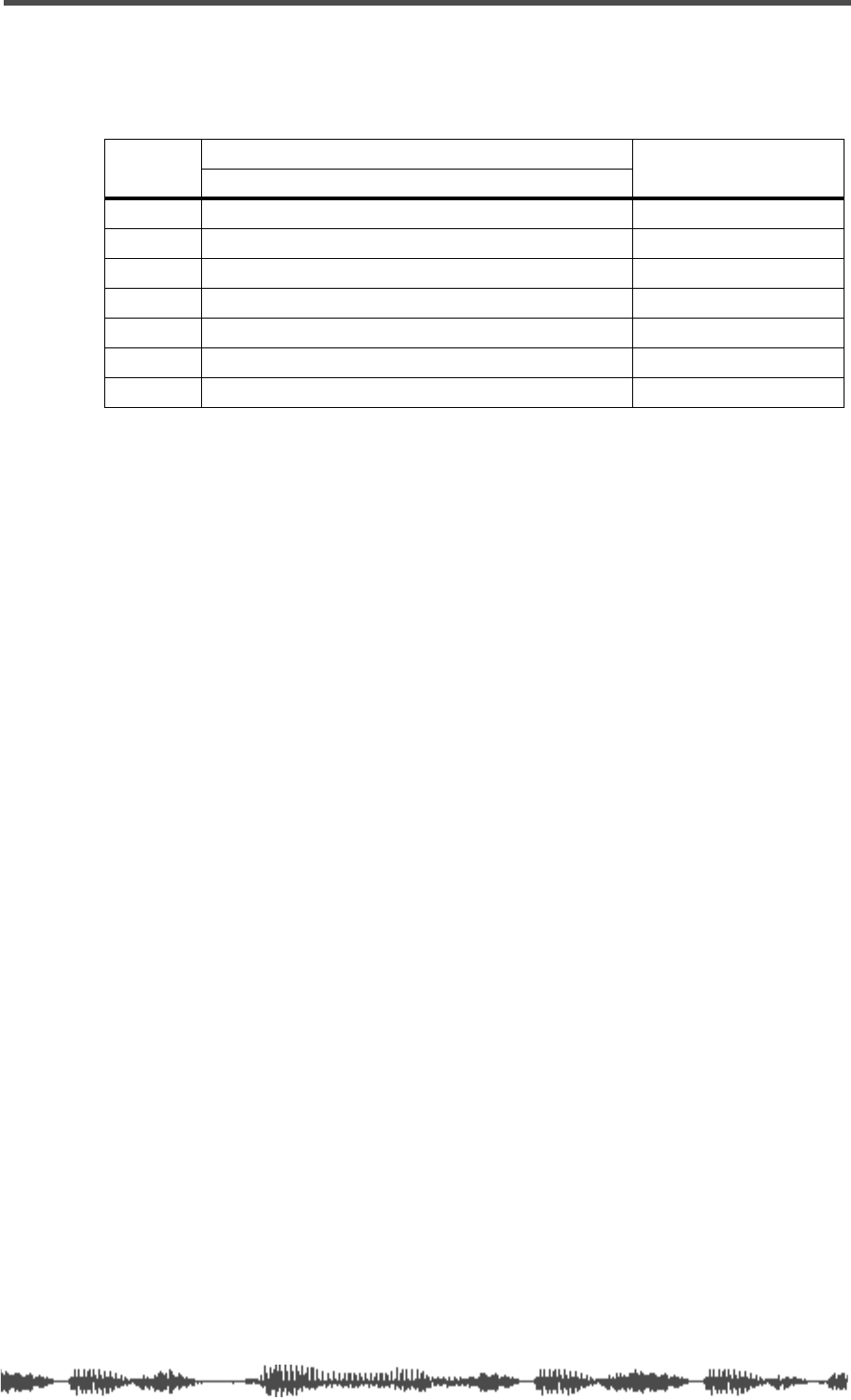
Faders
VM200 User’s Guide 33
The following table describes the function of the channel faders and
Master fader in each Fader Mode:
Fader function
CH Input Channel Master
Mode 1–8 (ANALOG IN) | 9–16 (ADAT IN) | 17–20 (EFF RTN)
CHANNEL Channel Gain ST BUSS Master Gain
AUX1 Channel to AUX1 Send Gain AUX1 Send Master Gain
AUX2 Channel to AUX2 Send Gain AUX2 Send Master Gain
AUX3 Channel to AUX3 Send Gain AUX3 Send Master Gain
AUX4 Channel to AUX4 Send Gain AUX4 Send Master Gain
EFF1 Channel to EFF1 Send Gain EFF1 Send Master Gain
EFF2 Channel to EFF2 Send Gain EFF2 Send Master Gain
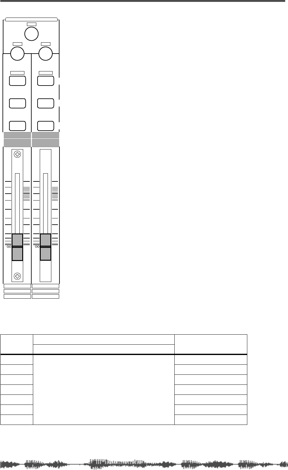
Touring the VM200
34 VM200 User’s Guide
[ON], [SOLO], & [EQ EDIT] Keys
The VM200 features eight sets of [ON],
[SOLO], and [EQ EDIT] keys, one set for each
channel fader.
The Master fader also features a [SOLO] key
and an [ON] key.
The following paragraphs summarize the
functions of these keys.
[ON] Keys
The [ON] keys basically turn channels on and
off.
In Channel Fader Mode, the channel [ON]
keys turn channels 1-8, 9-16, or 17-20 on or
off, depending on the channel layer you select
(using the Page Select keys).
The Master [ON] key controls various func-
tions depending on the current Fader Mode.
In Fader Mode Aux1 for example, [ON] key 1
turns channel 1 on and off, and the Master
[ON] key turns the Aux1 Out on and off. In
Fader Mode Eff2, On key 1 turns channel 1
on and off, and the Master [ON] key turns the
Eff2 Master on and off.
The [ON] keys can also transmit MMC com-
mands in MMC Send mode. (For more infor-
mation, see “MMC (MIDI Machine Control)
Send” on page 192.)
The following table describes the function of
the channel and Master [ON] keys in each
Fader Mode:
[ON] key function
CH Input Channel Master
Mode 1–8 (ANALOG IN) 9–16 (ADAT IN) 17–20 (EFF RTN)
CHANNEL
Channel ON/OFF
ST BUSS OUT ON/OFF
AUX1 AUX1 OUT ON/OFF
AUX2 AUX2 OUT ON/OFF
AUX3 AUX3 OUT ON/OFF
AUX4 AUX4 OUT ON/OFF
EFF1 EFF1 Master ON/OFF
EFF2 EFF2 Master ON/OFF
EQ/LO
+10
0
-10
-20
-30
-40
-
ON ON
SOLO SOLO
EQ EDIT EQ EDIT
10
2
9
1
18
17
FREQ Q
GAIN
+10
0
-10
-20
-30
-40
-
PANPAN
On keys
Solo keys
EQ Edit keys
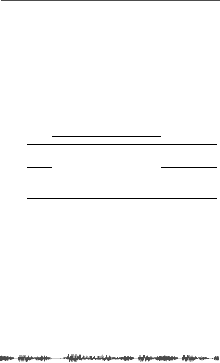
[SOLO] Keys
VM200 User’s Guide 35
[SOLO] Keys
The [SOLO] keys enable you to solo channels for monitoring.
The Solo Mode parameter on the SETUP:SYSTEM 1:CLOCK/MON function
page determines how signals from each channel will solo. They can
solo individually (PFL, or pre-fader listen) or after being mixed
together post-fader (M-SOLO, or mix solo).
In Channel Fader Mode, the [SOLO] keys solo channels 1-20, depend-
ing on the channel layer you select using the Page Select keys.
The [SOLO] keys control various functions depending on the current
Fader Mode. In Fader Mode Aux1 for example, [SOLO] key 1 solos
channel 1, and the Master [SOLO] key solos the AUX1 Buss. In Fader
Mode Eff2, [SOLO] key 1 solos channel 1, and the Master [SOLO] key
solos the Eff2 Send Master.
The following table describes the function of the Channel and Master
[SOLO] keys in each Fader Mode:
[SOLO] key function
CH Input Channel Master
Mode 1–8 (ANALOG IN) 9–16 (ADAT IN) 17–20 (EFF RTN)
CHANNEL
Channel Solo
ST BUSS Solo
AUX1 AUX1 Solo
AUX2 AUX2 Solo
AUX3 AUX3 Solo
AUX4 AUX4 Solo
EFF1 EFF1 Send Solo
EFF2 EFF2 Send Solo
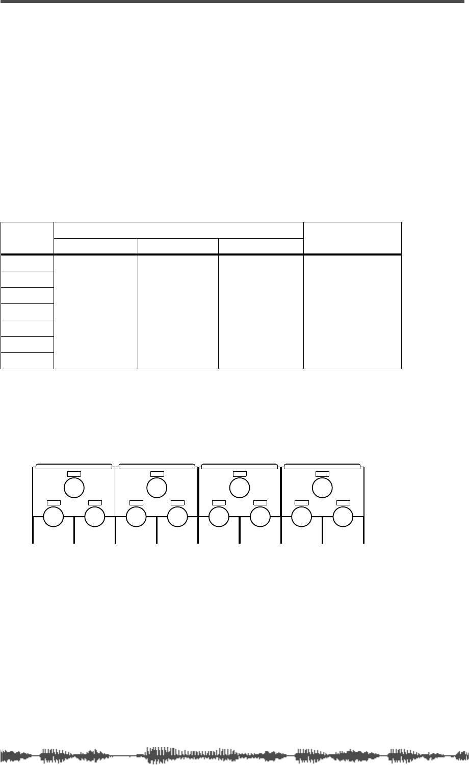
Touring the VM200
36
VM200 UserÕs Guide
[EQ EDIT] Keys
The
[EQ EDIT]
keys enable you to select channels for parameter edit-
ing.
When you press an
[EQ EDIT]
key, the VM200 displays the
EQ EDIT
function page for the selected channel (for example, EQ EDIT CH2).
This function page includes parameters that control a four-band
parametric equalizer. The bands are LO, LO-MID, HI-MID, and HI.
You can adjust the equalization by rotating the [GAIN], [FREQ], and
[Q] controls for each band.
For more information, refer to the table below, which describes the
function of the
[EQ EDIT]
key in different Fader Modes.
[EQ EDIT] key function
EQ Section Rotary Controls
The VM200 EQ section is horizontally subdivided into four sections:
EQ-LO, EQ/LO-MID, EQ/HI-MID, and EQ HI.
Each band features three knobs labelled Gain, Freq, and Q that con-
trol the parametric equalizer in EQ Edit mode.
The Gain rotary control sets the gain of the input preamps.
The Freq rotary control specifies the frequency.
The Q rotary controls adjust the selectivity of a filter. A narrow fre-
quency band indicates a high Q value; a wide frequency band indi-
cates a low Q values. (In the response curve, notice how a bell-shaped
curve grows wider as Q decreases.)
However, like many VM200 controls, in other operational modes the
EQ section knobs serve multiple purposes. For example, in Channel
Edit mode, the
[FREQ]
and
[Q]
knobs control the channels pan posi-
tion.
CH Input Channel Master
Mode 1–8 (ANALOG IN) 9–16 (ADAT IN) 17–20 (EFF RTN)
CHANNEL
Edits EQ for
Channels 1–8
(Disabled if
EQ Enable for
Channels 1–8 is
turned OFF.)
Edits EQ for
Channels 9–16
(Disabled if
EQ Enable for
Channels 9–16 is
turned OFF.)
Disabled N/A
AUX1
AUX2
AUX3
AUX4
EFF1
EFF2
EQ/HI
EQ/HI-MIDEQ/LO-MIDEQ/LO
GAIN
FREQ
PAN
Q
PAN
FREQ QFREQ Q
FREQ Q
GAINGAINGAIN
PANPANPANPANPANPAN
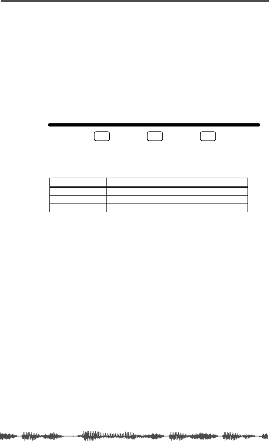
Page Select Keys
VM200 User’s Guide 37
Page Select Keys
The VM200 uses a channel-layer format, in which its nine faders per-
form multiple tasks to accommodate 20 input channels.
You can imagine the VM200 as being divided into three layers. Layer
1 provides access to Channels 1 through 8, which primarily handle
the analog inputs. Layer 2 provides access to Channels 9 through 16,
which are used with ADAT-compatible systems. Layer 3 provides
access to Channels 17-20, which are used primarily for effects
returns.
You can use the Page Select keys to select an appropriate channel
layer. The VM200 will display parameters appropriate for the channel
layer you specify.
When you press a Page Select key, it lights up, and the other two Page
Select keys remain dark or flashing.
Page Select Key Channels Displayed
1-8 ANALOG IN Channels 1 - 8 ANALOG IN
9-16 ADAT IN Channels 9 - 16 ADAT IN
17-20 EFF RTN Channels 17 - 20 EFFECT RETURN
1-8 ANALOG IN 9-16 ADAT IN 17-20 EFF RTN
PAGE SELECT
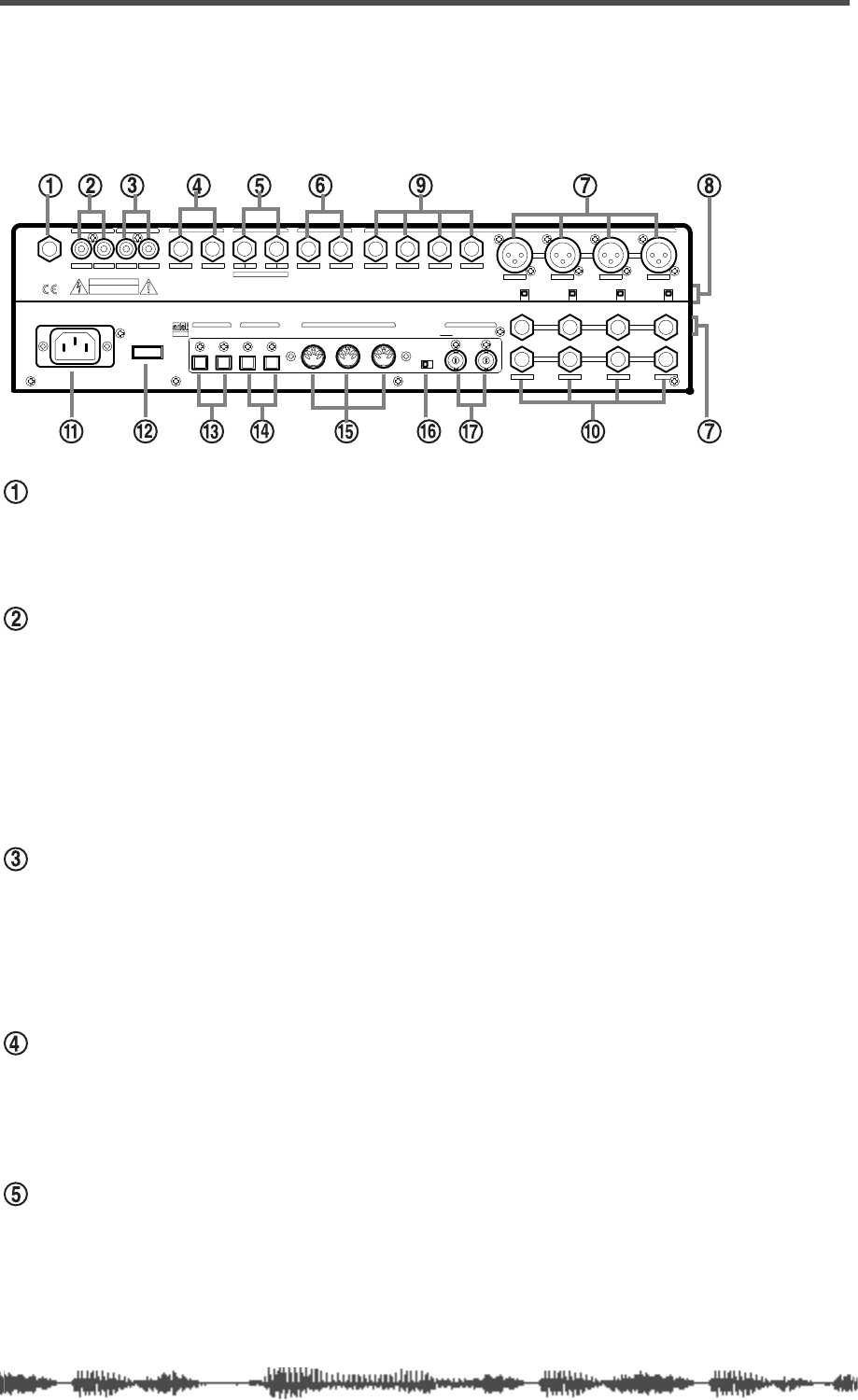
Touring the VM200
38 VM200 User’s Guide
Rear Panel
All inputs and outputs on the VM200 are conveniently located on
the rear panel. The following paragraphs briefly describe each input
and output.
PHONES
Connect a pair of stereo headphones to this stereo (TRS) phone jack.
Set the output level using the PHONES Gain knob on the top panel.
MONITOR OUT
Connect this pair of RCA phono jacks to the inputs on your monitor-
ing amplifier.
Select the monitor signal you wish to output through these jacks
using the MON SEL parameter on the SETUP:SYSTEM 1:CLOCK/MON func-
tion page (see “Setup Section” on page 23).
Set the output level using the MONITOR Gain knob on the top panel.
2TRK In
You can input a two-track signal, such as the stereo outputs from a
master recorder, to this pair of RCA phono jacks for confidence mon-
itoring.
Press the 2TRK IN switch on the top panel to monitor the signal.
ST BUSS OUT
The Stereo Buss Out (ST BUSS OUT) is a pair of unbalanced
1/4-inch phone jacks that outputs the left and right channels of the
main stereo mix.
REC BUSS OUT
The Rec Buss Out (REC BUSS OUT) is a pair of unbalanced
1/4-inch phone jacks that outputs the record buss.
When the ADD. AUX parameter is turned on, the REC BUSS OUT
outputs Aux Sends 3 and 4.
RISQUE ELECTRIQUECHOCDE
CAUTION
RISK OF ELECTRIC SHOCK
DO NOT OPEN
AVIS: NE PAS OUVRIR.
WARNING:
TO
SHOCK,DO NOT EXPOSE THIS EQUIPMENT
TO RAIN OR MOISTURE.
REDUCE THE RISK OF FIRE OR ELECTRIC
RLRLRLR4L3218765
1234
AAA
1234
+48V OFF
ON +48V OFF
ON +48V OFF
ON +48V OFF
ON
PHONES
OPTICAL
WORD
OUTIN
AC IN
POWER
S/P DIF
IN OUTOUTIN
MIDI
OUTTHRU
75
OFFON
INPUT
INSERT
B
INSERTINSERT
BB
ADD.AUX SEND
AUX SENDST BUSS OUT2TRK IN
MONITOR OUT REC BUSS OUT
IN
ADAT
Rear Panel
VM200 UserÕs Guide
39
AUX SEND
AUX SEND 1 and 2 are a pair of unbalanced 1/4-inch phone jacks
that can output an auxiliary signal to drive external effects, for
example.
Inputs 1 - 4: XLR or Phone Connectors (A or B)
Input channels 1 - 4 accept either balanced XLR inputs (XLR-3-32
type), or balanced/unbalanced (1/4-inch) phone plugs. (Input 1-4
Phones connectors accept either balanced or unbalanced analog
input.)
If you are inserting a phone plug, press the A/B switch for channels
1 through 4 to select the B inputs.
If you are inserting an XLR-type plug, leave the A/B switch
“unpressed” to select the A inputs. You can switch phantom power to
the XLR connectors on or off using switches located beneath each
connector. (Many condenser microphones, for example, require phan-
tom power.)
These inputs have a nominal input range of -60 dB to +10 dB.
+48 Phantom Power
Turn on this switch for XLR microphones or devices connected to
XLR inputs that require phantom power.
Inputs 5 - 8: Phone Connectors
Input channels 5 through 8 accept unbalanced phone plugs.
These inputs are designed for use with line-level sources (e.g., a syn-
thesizer keyboards, effects processors, or other devices).
These inputs have a nominal input range of -60 dB to +10 dB.
Inserts 1-4: Phone Connectors
The Insert connectors are stereo-type phone jacks.
You can connect an external effects unit to these connectors using an
insert cable to send the signal to the effects unit and return it to the
VM200. (For more information, see “Insert Channels 1–4” on page 62.)
The Insert connectors allow you to insert a signal into the signal chain
after the PAD switches and TRIM knobs.
AC In
Insert the female end of the AC power cable into this connector. Con-
nect the male end to an AC electrical outlet of the appropriate voltage
for your area.
Touring the VM200
40 VM200 User’s Guide
Power Switch
Use the power switch to turn the VM200 on and off.
S/P DIF IN/OUT
These are S/P DIF format optical digital connectors. You can con-
nect any S/P DIF equipped device (such as certain CD players, DAT
recorders, or computer soundcards) to these connectors.
For more information, see “S/P DIF IN/OUT” on page 168.
ADAT IN/OUT
These are Alesis ADAT Multichannel Optical Digital Interface con-
nectors. You can connect an 8-track digital multitrack recorder,
such as a Fostex VR-800 or other ADAT-compatible recorder, to
these connectors.
For more information, see “ADAT IN/OUT” on page 165.
MIDI IN, OUT, THRU
These standard MIDI ports enable you to connect the VM200 to
other MIDI devices. The MIDI IN port receives MIDI messages. The
MIDI OUT port outputs MIDI messages. The MIDI THRU port out-
puts all MIDI messages received by the MIDI IN port.
75Ω On, Off Switch
This switch turns WORD IN termination on and off. If the VM200 is
the last device to receive word clock via the WORD IN connection,
turn this termination switch on.
WORD IN/OUT
The Word In and Out connectors are connected to the WORD OUT
and IN connectors of digital devices to receive and send word clock
information for digital sync operation.
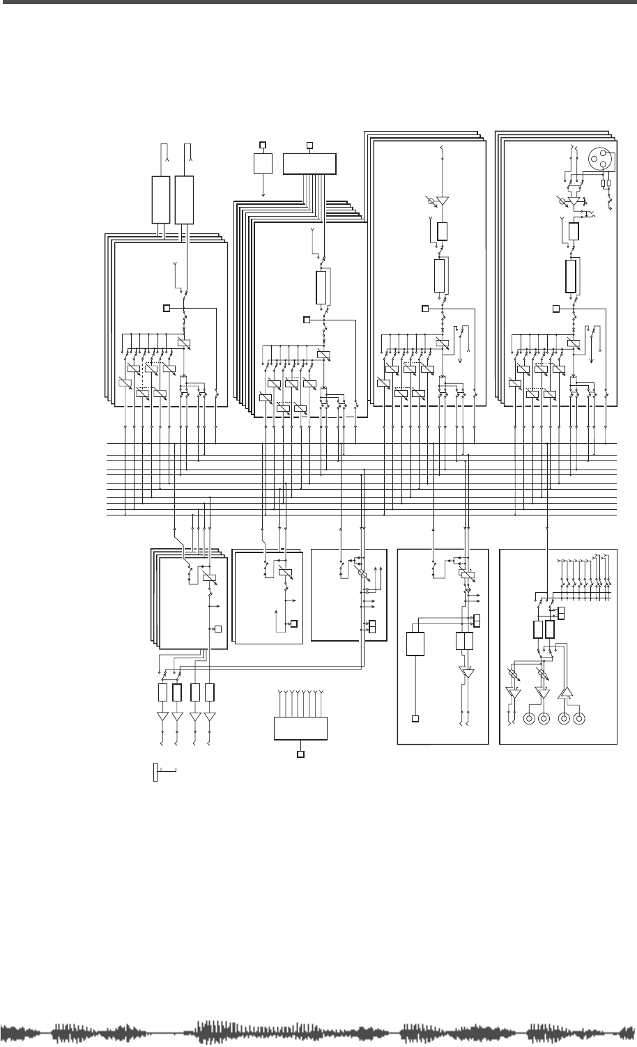
Block Diagram
VM200 User’s Guide 41
Block Diagram
ADC
ADC
INPUT 1(2-4)A
(+10~-60dBV)
INPUT 1(2-4)B
(+10~-60dBV) A/B
+48V +48V
PAD 26dB
INSERT
(-10dBV)
TRIM
(-16~-60dB)
S/P DIF IN L(R)
S/P DIF
ASSIGN
4BAND PARA EQ
M
EQ ON CH ON
ADAT BUSS
DIRECT
From REC BUSS
REC BUSS-L(R)
ADAT OUT 1(2-4)
GAIN
M-SOLO
CONTROL
EFF1
POST/ PRE
EFF2
POST/ PRE
AUX1
AUX2
POST/ PRE
POST/ PRE
AUX3
POST/ PRE
POST/ PRE
AUX4
SOLO (PFL)
ASSIGN
ST BUSS
PAN
ASSIGN
REC BUSS
CH1-4 (ANALOG IN 1-4)
INPUT5 (6-8)
(-10~-50dBV)
TRIM
(-10~-50dB)
S/P DIF IN L (R)
S/P DIF
ASSIGN
4BAND PARA EQ
EQ ON
ADAT BUSS
DIRECT
CH ON
From REC BUSS
REC BUSS-L (R)
ADAT OUT 5 (6-8)
GAIN
M-SOLO
CONTROL
SOLO (PFL)
ASSIGN
ST BUSS
PAN
ASSIGN
REC BUSS
EFF1
POST/ PRE
EFF2
POST/ PRE
AUX1
POST/ PRE
AUX2
POST/ PRE
AUX3
POST/ PRE
AUX4
POST/ PRE
CH5-8 (ANALOG IN 5-8)
M
4BAND PARA EQ
M
ADAT IN ADAT
DECODE
S/P DIF IN S/P DIF
DECODE
To CH1-20
S/P DIF IN
S/P DIF IN L (R)
S/P DIF
ASSIGN EQ ON
CH9-16 (ADAT IN 1-8)
M-SOLO
CONTROL
GAIN
CH ON
POST/ PRE
EFF1
POST/ PRE
EFF2
POST/ PRE
AUX1
POST/ PRE
AUX2
POST/ PRE
AUX3
POST/ PRE
AUX4
SOLO (PFL)
ASSIGN
ST BUSS
PAN
ASSIGN
REC BUSS
M
EFFECT 1
EFFECT 2
From EFF Master
EFF1
From EFF Master
EFF2
S/P DIF
ASSIGN
S/P DIF IN L (R)
CH ON
M-SOLO
CONTROL
GAIN
EFF1
POST/ PRE
EFF2
POST/ PRE
AUX1
POST/ PRE
AUX2
POST/ PRE
AUX3
POST/ PRE
AUX4
POST/ PRE
SOLO (PFL)
ASSIGN
ST BUSS
PAN
EFF1 ASSIGN
REC BUSS
EFF2
AUX1
AUX2
AUX3
AUX4
CH17-20
(EFF RTN)
MM
DAC
DAC
ST-BUSS (L)
ST-BUSS (R)
REC-BUSS (L)
EFF1
EFF2
AUX1
AUX4
AUX3
AUX2
SOLO
(PFL)
2 TRK IN MON
GAIN
PHONES
GAIN
L
2 TRK IN
(-10dBV)
R
L
R
MON
(-10dBV)
PHONES
MONITOR
DAC
DAC
ST BUSS
ST-BUSS
MASTER
To MONITOR
ON
SOLO (PFL)
S/P DIF
ENCODE
L
ST
R
(-10dBV)
S/P DIF OUT
ADAT
ENCODE ADAT OUT
To CH1, 3, 5, 7
To CH2, 4, 6, 8
REC-BUSS
MASTER
To MONITOR
SOLO (PFL)
REC BUSS
M
EFF1 (2)
MASTER
ON
SOLO (PFL)
To MONITOR
To EFF1 (2)
EFF1-2
M
To MONITOR
MASTER
AUX1 (2-4)
ON
SOLO (PFL)
AUX1-4
DAC
DAC
DAC
DAC
ADD. AUX MODE
AUX1
(-10dBV)
AUX2
(-10dBV)
(-10dBV)
LAUX3
REC BUSS OUT
RAUX4
(-10dBV)
ADD.AUX MODE
MM
MM
ADAT OUT1
ADAT OUT2
ADAT OUT3
ADAT OUT4
ADAT OUT5
ADAT OUT6
ADAT OUT7
ADAT OUT8
REC-BUSS (R)
EFF1
EFF2
AUX1
AUX2
AUX3
AUX4
EFF1
EFF2
AUX1
AUX2
AUX3
AUX4
EFF1
EFF2
AUX1
AUX2
AUX3
AUX4
*
*
*
*
**
*
*
* When SMOOTHING LEVEL 2 is selected,
each gain is automatically set to be the same.

Touring the VM200
42 VM200 User’s Guide

DIGITAL RECORDING MIXER
VM200
REC BUSS
EFF EDITSELECTED EQ
EQ/HI
EQ/HI-MIDEQ/LO-MID
+10
0
-10
-20
-30
-40
-
+10
0
-10
-20
-30
-40
-
+10
0
-10
-20
-30
-40
-
+10
0
-10
-20
-30
-40
-
+10
0
-10
-20
-30
-40
-
+10
0
-10
-20
-30
-40
-
+10
0
-10
-20
-30
-40
-
GAIN
FREQ
PAN
Q
PAN
ON ON ON ON ON ON ON
SOLO SOLO SOLO SOLO SOLO SOLO SOLO
EQ EDIT EQ EDIT EQ EDIT EQ EDIT EQ EDIT EQ EDIT EQ EDIT EQ EDIT
SOLO
ON ON
SOLO
EQ LIBRARY
STORERECALL
EQ ON
EFF LIBRARY
STORERECALL
EFF2EFF1
RECALLSOLO
EXIT
14
6
13
5
12
4
11
3
2019
FREQ QFREQ Q
Q
GAINGAIN
9-16 ADAT IN 17-20 EFF RTN
P
AGE SELECT
GROUP
PAIR/
METER
CHANNEL/
MIN MAX
+10
0
1
0
1
0
0
-10
-20
-30
-60
-
-40
MMC SEND
PANPANPANPANPANPAN
-40
-36
-24
-18
1212
ST BUSS/SOLO
L R
VM200 User’s Guide
43
CHAPTER 3
Getting Started
About This Chapter
This chapter is designed to help get you started quickly using your
VM200.
It explains how to plug in the power cord, connect to an amplifier,
plug in a microphone or other source, turn on the VM200, adjust a
few controls, try out some EQ settings and Effect presets, and record
a stereo signal to an external recorder.
However, please read the
Precautions,
“Introducing the VM200” on
page 9
and “Touring the VM200” on page 17 before you “get started.”
Chapter Contents
VM200 System Example . . . . . . . . . . . . . . . . . . . . . . . . . . 44
Connecting the Power Cord . . . . . . . . . . . . . . . . . . . . . . . 45
Turning the VM200 On and Off . . . . . . . . . . . . . . . . . . . . . 45
A Few Tips on Using the VM200 . . . . . . . . . . . . . . . . . . . . . 46
Channel Layers . . . . . . . . . . . . . . . . . . . . . . . . . . . . . . . . . 46
Keeping It Digital . . . . . . . . . . . . . . . . . . . . . . . . . . . . . . . . 48
An Important Note About Word Clock Information . . . . . . . 48
Stopless Rotary Controls . . . . . . . . . . . . . . . . . . . . . . . . . 48
Lower and Raise Faders to Initiate Sends . . . . . . . . . . . . . 49
Reading the Display . . . . . . . . . . . . . . . . . . . . . . . . . . . . . . 49
Function Page Parameter Matrix . . . . . . . . . . . . . . . . . . . . 50
Lit & Flashing LED Keys . . . . . . . . . . . . . . . . . . . . . . . . . 51
Finally...Let’s Get Started! . . . . . . . . . . . . . . . . . . . . . . . . . 52
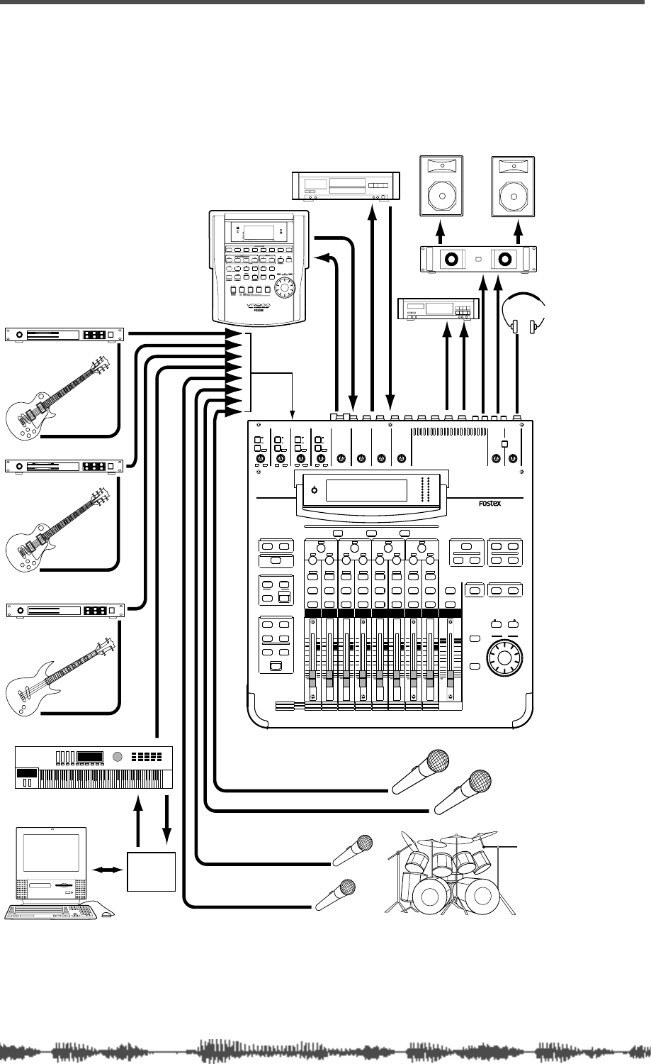
Getting Started
44
VM200 User’s Guide
VM200 System Example
The following illustration shows one example of a recording studio
based on the VM200.
INPUT 4INPUT 3INPUT 2INPUT 1
PAD
26dB
A
B
PAD
26dB
A
B
PAD
26dB
A
B
PAD
26dB
A
B
-16 -60
+10 -34
-16 -60
+10 -34
-16 -60 -16 -60
TRIMTRIMTRIMTRIM
DIGITAL RECORDING MIXER
VM200
SCENE MEMORYREC BUSS
EFF EDITSELECTED EQ
EQ/HI
EQ/HI-MIDEQ/LO-MIDEQ/LOSETUP
CURRENT SCENE STATUS
KEY MODE
+10
0
-10
-20
-30
-40
-
+10
0
-10
-20
-30
-40
-
+10
0
-10
-20
-30
-40
-
+10
0
-10
-20
-30
-40
-
+10
0
-10
-20
-30
-40
-
+10
0
-10
-20
-30
-40
-
+10
0
-10
-20
-30
-40
-
16
8
GAIN
FREQ
PAN
Q
PAN
ON ON ON ON ON ON ON
SOLO SOLO SOLO SOLO SOLO SOLO SOLO
EQ EDIT EQ EDIT EQ EDIT EQ EDIT EQ EDIT EQ EDIT EQ EDIT EQ EDIT
SOLO
ON ON
SOLO
EQ LIBRARY
STORERECALL
EQ ON
EFF LIBRARY
STORERECALL
EFF2EFF1
STORERECALLSOLO
+1/ /-1
DATA
EXIT
ENTER
MASTER
15
7
14
6
13
5
12
4
11
3
10
2
9
1
2019
18
17
FREQ QFREQ Q
FREQ Q
GAINGAINGAIN
1-8 ANALOG IN 9-16 ADAT IN 17-20 EFF RTN
PAGE SELECT
SYSTEM MIDI
PHASE GROUP
ROUTING/ PAIR/
CH VIEW METER
CHANNEL/
AUX1
FADER MODE
AUX2
AUX3 AUX4
EFF1 EFF2
CHANNEL
ADD.AUX
TRIM
-10 -50
TRIM TRIM TRIM
-10 -50 -10 -50 -10 -50
INPUT 5 INPUT 6 INPUT 7 INPUT 8
MIN MAX
GAIN
MAXMIN
GAIN
2TRK IN
PHONESMONITOR
+10
0
-10
-20
-30
-40
-
EFF RTN
ADAT IN
ANALOG IN
0
-10
-20
-30
-60
-
-40
MMC SEND
PANPANPANPANPANPAN
-48
-36
-24
-18
-12
-9
-6
-3
OL
ST BUSS/SOLO
LR
METER
+10 -34 +10 -34
ANALOG IN
DAT
ADAT compatible
Monitor speakers
Monitor amplifier
Master recorder
Vocal
Chorus
Drums
MIDI
Interface
MIDI keyboard
Bass guitar
Second guitar
Lead guitar
Guitar processor
ADAT OUT
ADAT IN
S/P DIF OUT
S/P DIF IN
ST BUSS OUT
MONITOR OUT
PHONES
MIDI IN
MIDI OUT
Guitar processor
Bass processor
Headphones

Connecting the Power Cord
VM200 User’s Guide
45
Connecting the Power Cord
Use the included power cord to connect the VM200 to an appropriate
AC electrical outlet. Insert the female end into the AC input on the
rear panel of the VM200. Insert the male end into a wall outlet of an
appropriate voltage for your area.
Turning the VM200 On and Off
The power button is located on the rear panel of the VM200 next to
the AC power cable input jack. When you power on your audio com-
ponents, be certain to follow this sequence to prevent damage to your
equipment:
1.
Connect all instruments and sound sources, including key-
boards, drum machines, etc.
2.
Turn on the power to all sound sources.
3.
Turn on the power to the VM200 by depressing the power but-
ton on the rear panel.
The VM200 displays the Fostex and VM200 logos, then the
CHAN-
NEL EDIT
function page. (For more information on the
CHANNEL EDIT
function page, see “The Channel Edit Function Page” on page 49.)
4.
Make sure the volume on your monitor amplifier is not set too
loud, then turn on the power to the monitor amplifier.
When you turn
off
the power to the VM200, be sure to follow this
sequence in reverse. (That is, first turn off the monitor amplifier, then
the VM200, then the sound sources.)
Warning:
Turn off the power to all connected electronic equipment
before making any connections to the VM200.

Getting Started
46
VM200 User’s Guide
A Few Tips on Using the VM200
If you have experience using analog audio mixers, a few things about
the VM200 Digital Recording Mixer may be new to you. This section
introduces some of the advantages of working with a digital mixer.
Channel Layers
If a conventional analog mixing console has 16 or 24 input channels,
it also likely has16 or 24 faders, the same number of
[ON]
keys and
[SOLO]
keys, etc. Each input channel is a complete module, with its
own dedicated set of input connector, preamp, etc. This type of
design can work well, but is redundant and subject to analog noise.
The VM200 is a
digital
recording mixer, and does not conform to ana-
log recording conventions.
The VM200 uses an innovative “channel layering” system that
enables you to control up to 20 channels using only eight faders and
one Master Fader.
You press one of three Page Select keys to specify the active channel
layer. The faders, rotary controls, and various keys then control a
channel on the selected layer, and the LCD Display shows parameters
specific to the selected layer.
For example, Fader 1 can control input channels 1, 9, or 17 depend-
ing on the selected channel layer. (It can also control various send lev-
els, depending on the current mixer routing.)
You can select one of the following layers by pressing the appropriate
Page Select key:
• Channels 1 - 8 Analog In
• Channels 9 - 16 ADAT In
• Channels 17 - 20 Eff Rtn
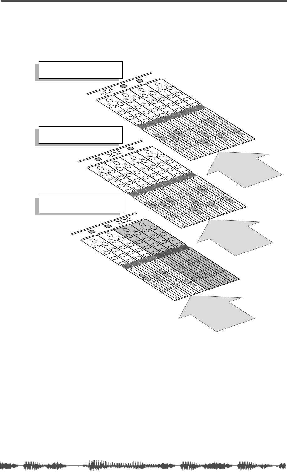
Channel Layers
VM200 User’s Guide
47
The following diagram illustrates the three channel layers of the
VM200:
EQ/HI
EQ/HI-MID
EQ/LO-MID
EQ/LO
+10
0
-10
-20
-30
-40
-
+10
0
-10
-20
-30
-40
-
+10
0
-10
-20
-30
-40
-
+10
0
-10
-20
-30
-40
-
+10
0
-10
-20
-30
-40
-
+10
0
-10
-20
-30
-40
-
+10
0
-10
-20
-30
-40
-
GAIN
FREQ
PAN
Q
PAN
ON ON ON ON ON ON ON
SOLO SOLO SOLO SOLO SOLO SOLO SOLO
EQ EDIT EQ EDIT EQ EDIT EQ EDIT EQ EDIT EQ EDIT EQ EDIT EQ EDIT
SOLO
ON
FREQ Q
FREQ Q
FREQ Q
GAIN
GAIN
GAIN
+10
0
-10
-20
-30
-40
-
PANPANPANPANPANPAN
1-8 ANALOG IN 9-16 ADAT IN 17-20 EFF RTN
PAGE SELECT
PAN
EQ/HI
EQ/HI-MID
EQ/LO-MID
EQ/LO
+10
0
-10
-20
-30
-40
-
+10
0
-10
-20
-30
-40
-
+10
0
-10
-20
-30
-40
-
+10
0
-10
-20
-30
-40
-
+10
0
-10
-20
-30
-40
-
+10
0
-10
-20
-30
-40
-
+10
0
-10
-20
-30
-40
-
GAIN
FREQ
PAN
Q
ON ON ON ON ON ON ON
SOLO SOLO SOLO SOLO SOLO SOLO SOLO
EQ EDIT EQ EDIT EQ EDIT EQ EDIT EQ EDIT EQ EDIT EQ EDIT EQ EDIT
SOLO
ON
FREQ Q
FREQ Q
FREQ Q
GAIN
GAIN
GAIN
+10
0
-10
-20
-30
-40
-
PANPANPANPANPANPAN
1-8 ANALOG IN 9-16 ADAT IN 17-20 EFF RTN
PAGE SELECT
1 2 3 4 5 6 7 8
ANALOG IN
ADAT IN
9 10 11 12 13 14 15 16
EFF RTN
17 18 19 20
The [1–8 ANALOG IN] key is lit.
You can control channels 1–8.
The [9–16 ADAT IN] key is lit.
You can control channels 9–16.
The [17–20 EFF RTN] key is lit.
You can control channels 17–20.

Getting Started
48
VM200 User’s Guide
Keeping It Digital
Many home studios or project studios these days record to digital
audio tape or hard disk recording systems, but lacking a digital
mixer, they are forced to mix tracks using a conventional analog
mixer. This can actually add color and warmth to some tracks, but
is likely to introduce noise into the signal chain.
Once an instrument or singer’s voice has been converted to digital
audio by an analog-to-digital (A/D) converter, it is generally best to
leave the recording in the digital domain. Running the signal back
and forth through A/D and D/A converters, regardless of the quality
of the converters, unnecessarily reduces the overall quality of the sig-
nal, and hence the final recording.
With the VM200, you can record and mixdown entirely in the digital
domain. This may make a dramatic improvement in the quality of
your final recordings.
An Important Note About Word Clock Information
Before you can transfer digital audio from one device to another, the
digital audio equipment must be word clock synchronized, or timing
problems may result.
For example, if you are recording to another digital device, such as an
ADAT, DAT, or digital multitracker, you must synchronize all digital
components in your recording system to a common word clock
source.
If the VM200 is the only digital component in your recording system,
you do not need to adjust any word clock settings.
However, if you are using other digital audio components, please refer
to “Digital Connections, Word Clocks, and Sample Rates” on
page 160 for more information on synchronizing to a common word
clock source.
Stopless Rotary Controls
The VM200 uses the 12 rotary controls (also known as the Gain,
Freq, and Q controls) to adjust values for several different parame-
ters, depending on the currently-selected function page.
Unlike conventional analog control knobs, the rotary controls on the
VM200 are stopless; you can rotate them right or left endlessly.
In this way, the knobs can more easily accommodate a broad range
of parameter values.
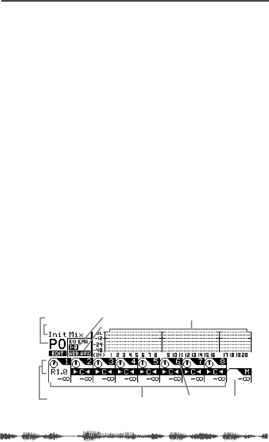
Lower and Raise Faders to Initiate Sends
VM200 User’s Guide
49
Lower and Raise Faders to Initiate Sends
If on occasion you think you have configured the VM200 to send a
particular signal to a buss, but you unexpectedly cannot hear the
output, try bringing the fader down and raising it back up to the
desired level to initiate the send.
This may seem unusual if you are used to analog mixers, but it is part
of the channel layer structure of the VM200. Because the faders can
control multiple functions depending on the displayed function page,
you may need to lower and raise the faders to set new levels when you
change Fader Modes.
For example, after you set the level of channels 19 and 20 for an effect
return, if you wish to set the effect send level on channel 3, you may
need to lower the Channel 3 and Master faders once, then raise them
to set the desired level.
Reading the Display
The LCD Display features a resolution of 256 x 64 dots. It can dis-
play numerical parameter values, and uses graphic icons to repre-
sent fader positions and rotary control settings.
This section shows a few sample function pages and explains common
icons and indicators.
The Channel Edit Function Page
Whenever you turn on the power to the VM200 or press the
[CHANNEL/METER]
key or the
[EXIT]
key, the VM200 displays the
CHANNEL EDIT
function page.
There are actually two versions of the Channel Edit page. One version
shows the inputs; the other version shows the outputs. (The Channel
Edit/Input version is shown below.)
When you see this function page, the VM200 is in Channel Edit mode.
You can think of the
CHANNEL EDIT
function pages as a type of “home”
page.
scene title
input channel meters
scene program number
channel pan settings channel number
selected EQ
ADD.AUX or Rec Buss
channel fader levels master fader level
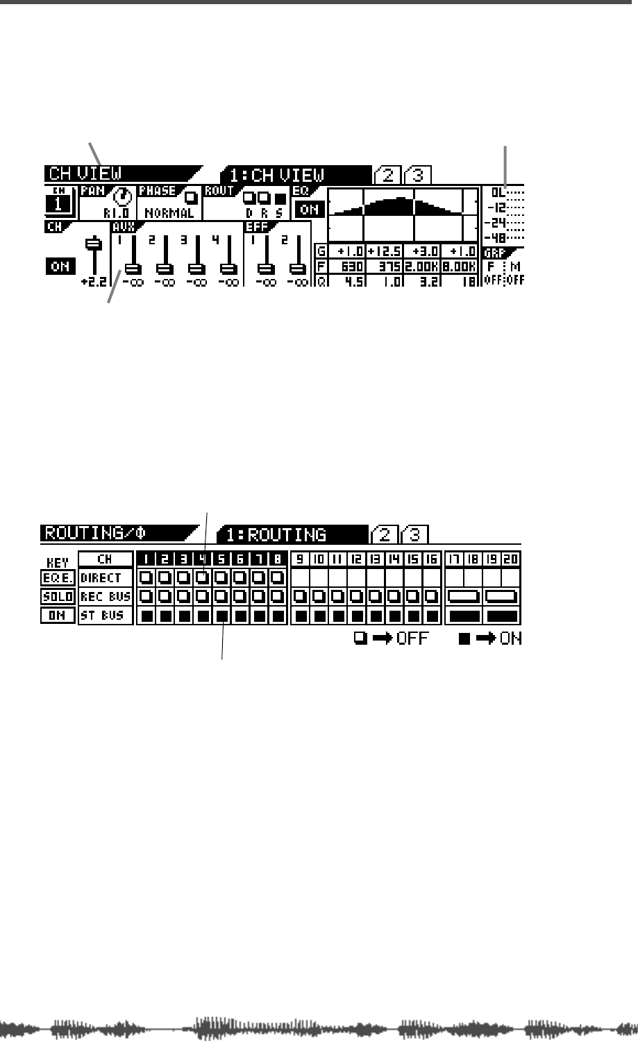
Getting Started
50
VM200 User’s Guide
Examples of Other Function Pages
The name of the function page appears in the upper-left corner.
Note how the fader icons look like little faders on the following
CHANNEL
VIEW (CH VIEW)
function page.
You use the
[EQ EDIT]
,
[SOLO]
, and
[ON]
keys to toggle two-state indi-
cators. These indicators are represented on the display by small rect-
angles.
An empty rectangle indicates that the parameter or option is turned
“off.” A “filled” or solid dark rectangle indicates an “on” setting. (This
manual also refers to darkened indicators as “highlighted,” just to
confuse the tourists.)
Function Page Parameter Matrix
The display frequently arranges the parameters on a function page
in a matrix.
One such matrix displays four rectangles in a horizontal row, with
each rectangle containing a parameter. Beneath this appears another
row, which contains eight rectangles, as illustrated below.
On such a function page, the four Gain rotary controls adjust param-
eters in the top row, and the Freq and Q rotary controls adjust the
parameters in the bottom row.
Function Page Name
Fader icons show fader position.
Level indicator
Filled or dark rectangle means “on”
Empty rectangle means “off”
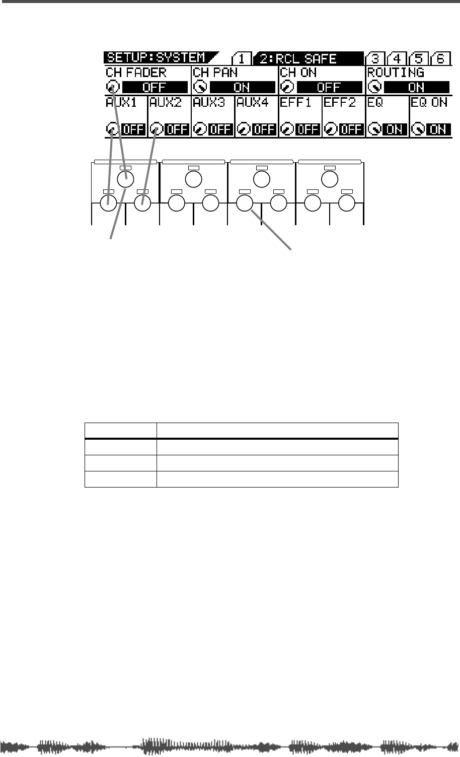
Lit & Flashing LED Keys
VM200 User’s Guide
51
Lit & Flashing LED Keys
Many of the keys on the control surface of the VM200 are translu-
cent and fixed in position over an LED light that can provide status
information.
In general, these keys flash when they are available for selection, and
light up continuously when they are selected. (Don’t be alarmed the
first time you press the Routing function key and a couple dozen
lights start flashing! This is normal.)
LED Condition Meaning
dark
off, deselected
flashing
available for selection
lit
on, selected
EQ/HI
EQ/HI-MIDEQ/LO-MIDEQ/LO
GAIN
FREQ
PAN
Q
PAN
FREQ QFREQ Q
FREQ Q
GAINGAINGAIN
PANPANPANPANPANPAN
For example, use the EQ/LO Gain rotary control Use the EQ/HI-MID Freq rotary control
to turn the CH FADER parameter on and off. to turn the EFF1 parameter on and off.
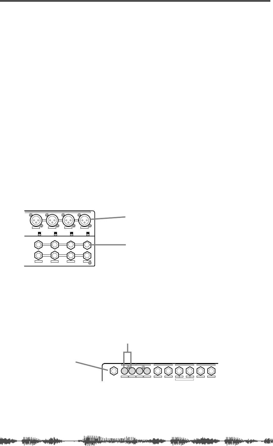
Getting Started
52
VM200 User’s Guide
Finally...Let’s Get Started!
The following procedure lets you try out some of the capabilities of
your VM200. To simplify the explanation, in this procedure we will
connect a microphone to channel 1, adjust the EQ, apply effects, and
record the signal.
Making Connections
This procedure assumes that you have installed and powered on the
VM200. (See page 45 for more information.)
1.
Connect a microphone, instrument, or other sound source to
input channel 1.
You can connect either:
• a balanced XLR-type condenser microphone to input channel 1,
connector A, and leave the Input A/B selector button on the top
panel unpressed; or
• a balanced/unbalanced TRS-type microphone to input channel
1, connector B, and depress the Input A/B selector button.
However, you can use another sound source, such as a synthe-
sizer keyboard or CD player, if you desire. Make sure it is powered
off before you connect it to the VM200.
2.
Connect the VM200 MONITOR OUT to an amplifier and
speakers, or connect a pair of stereo headphones to the
PHONES jack.
You can use the Monitor Gain or Phones Gain knobs to adjust the
output volume level. Lower the Gain to minimum to prevent loud
noise.
3.
Connect the ST BUSS OUT to the analog inputs of a recorder.
Even though the VM200 is a digital mixer designed primarily for
use with digital multitrack recorders, to simplify this brief proce-
dure, we will connect to an analog recorder.
1234
AAA
1234
+48V OFF
ON +48V OFF
ON +48V OFF
ON +48V OFF
ON
INPUT
INSERT
B
INSERTINSERT
BB
XLR-type connector (A)
1/4” phone connector (B)
RLRLRLR4L321
PHONES
ADD.AUX SEND
AUX SENDST BUSS OUT2TRK IN
MONITOR OUT REC BUSS OUT
MONITOR OUT
PHONES
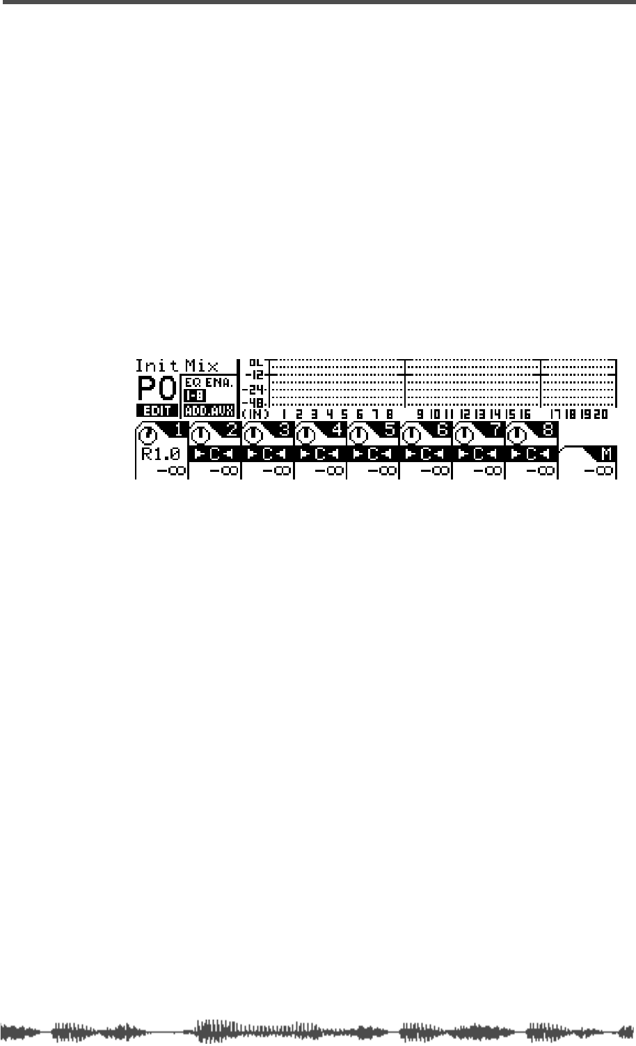
Powering On
VM200 User’s Guide
53
If you prefer, you can connect a DAT to the S/P DIF OUT or an
ADAT-compatible recorder to the ADAT OUT connectors. (For
more information, see “Digital Connections” on page 159.).
If you just want to try out the EQ and some effects, you can skip
this step (step 3) altogether.
4.
Lower all faders and Gain and Trim knobs on the VM200.
Powering On
5.
Press the Power button on the rear panel to turn on the power
to the VM200.
The VM200 banner scrolls, all keys flash, then the VM200 dis-
plays the
CHANNEL EDIT/INPUT
function page.
The
[1–8 ANALOG IN]
Page Select key lights up red. All
[ON]
keys,
the
[CHANNEL/METER]
key, and the
[CHANNEL]
key light up green.
6.
Turn on the microphone (or other connected sound source),
then turn on the power to the amplifier.
If you are using an XLR-type condenser microphone connected to
the XLR input, turn on the +48 phantom power to the microphone
using the phantom power switch on the rear panel.
Adjusting the Channel Input
Make sure that the
[ON]
keys for channel 1 and Master are lit. If not,
press the
[ON]
keys to turn them on.
Also, make sure that the 2TRK IN button is NOT depressed.
7.
While talking or singing into the microphone (or playing an
alternate sound source), adjust the channel 1 Trim control,
and raise the channel 1 fader and the Master fader.
Notice the movement in the level meter for input channel 1 on the
LCD Display, and in the ST BUSS LED meter to the right of the
display.
Adjust the input channel level so that the meter will not reach the
“OL” (overload) level.
8.
Raise the monitoring level using the Monitor Gain control for
connected monitoring speakers, or the Phones Gain control
for connected headphones.
Set this to the desired listening level.
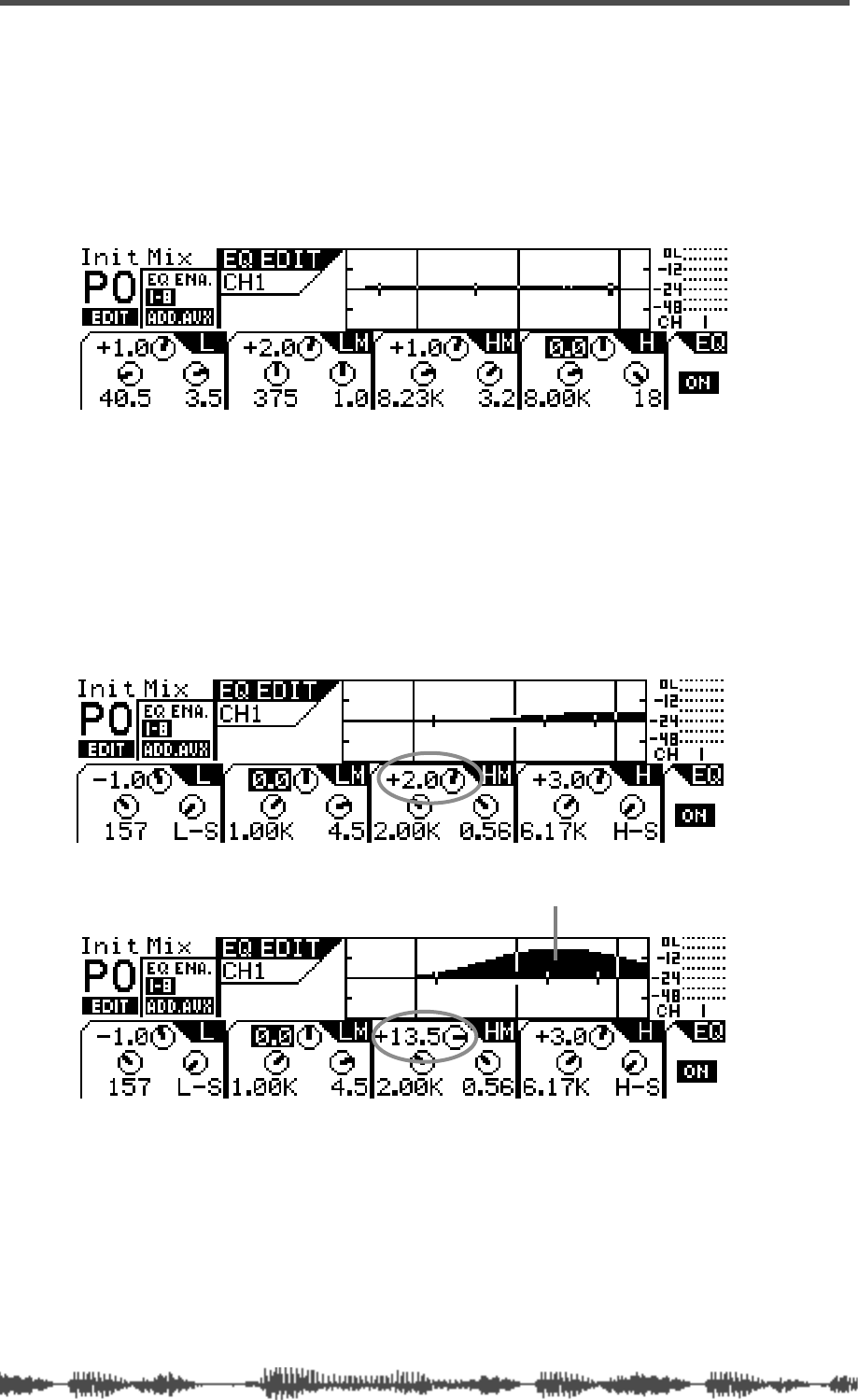
Getting Started
54
VM200 User’s Guide
Adjusting the EQ
9.
Press the channel 1
[EQ EDIT]
key.
The
[EQ EDIT]
key lights up orange, and the
[EQ ON]
key in the
Selected EQ section lights up green.
If the
[EQ ON]
key is not lit, press the key to turn it on.
The following
EQ EDIT
function page appears.
10.
Use the EQ Gain, Freq, and Q rotary controls to adjust the
channel 1 EQ.
Each trio of rotary controls adjusts the EQ in a separate fre-
quency band. Use all 12 rotary controls to adjust the channel 1
EQ in each of the four bands.
For example, watch the response curve swell as you raise the
EQ/HI-MID Gain, as illustrated in figures A and B below.
A
B
the response curve swells when Gain is raised

Adjusting the EQ
VM200 User’s Guide
55
If you lower the Freq, the soft bell-shaped curve in Figure B would
move to the left, as illustrated in Figure C:
In Figures D and E below, notice how the frequency range changes
and the response curve sharpens and narrows as the EQ/HI-MID
Q value is raised.
You can store EQ settings in a program, or you can recall a preset
EQ program. Refer to “EQ” on page 75 for more information.
C
D
E
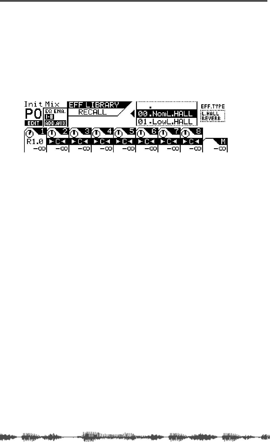
Getting Started
56
VM200 User’s Guide
Audition Some Effects
Let’s apply some effects from the Eff2 effect processor to the signal.
11.
Press the
[EFF2]
key in the Eff Edit section.
The [EFF2] key lights up orange and the VM200 displays the
EFF
EDIT
function page.
12.
Press the
[RECALL]
key in the Eff Library section.
The VM200 displays the following
EFFECT LIBRARY RECALL
function
page, and the
[EFF2]
key flashes.
13.
Use the Data Wheel or the
[>/-1]
and
[+1/<]
keys to scroll or
step through the effects list and select an effect program.
Try something like the Mono Delay or a Large Hall Reverb.
14.
Press the
[ENTER]
key to confirm the selection.
The VM200 displays the
EFF EDIT
function page.
15.
Press the
[CHANNEL/METER]
key.
The VM200 displays the
CHANNEL EDIT
function page.

Recording
VM200 User’s Guide
57
16.
Press the
[17–20 EFF RTN]
Page Select key.
The [1–8 ANALOG IN] key LED turns off and the [17–20 EFF RTN] key
lights up red.
17. Make sure that the [ON] keys for channels 19 and 20 are lit,
and lower then raise the faders for channels 19 and 20 to set
the effects return channel level.
You must lower then raise the faders to set the return level.
EFF1 is routed to EFF RTN 17 and 18, and EFF2 is routed to EFF
RTN 19 and 20.
18. Make sure that the Master [ON] key is lit, then raise the Mas-
ter fader to set the effects return master level.
19. Press the [1–8 ANALOG IN] Page Select key.
The [17–20 EFF RTN] key LED turns off and the [1–8 ANALOG IN]
Page Select key lights up.
20. Press the [EFF2] key in the Fader Mode section.
The [EFF2] key flashes orange and the [AUX2] key flashes red in the
Fader Mode section. (Don’t worry about the flashing [AUX2] key for
the moment.)
21. Lower then raise the channel 1 fader and the Master fader to
set the desired effects send signal level.
As you raise the faders, you should hear the effect.
You can also edit and store effects settings. Refer to “Effects” on
page 123 for more information.
Of course, you can connect other instruments to other analog chan-
nels, or connect a DAT or CD player to the S/P DIF In connector for
mixdown and recording.
Recording
22. Set up your connected recorder accordingly and press the
REC and PLAY button on the recorder to begin recording.
You can now record your performance to the recorder.
To check the input and output levels of the VM200, press the
[CHANNEL/METER] key to toggle between the input and output
meters.
Storing a Mix Scene
Once you are satisfied with the mix settings, you can save them as a
scene “snapshot” in the VM200’s Scene Memory. You can also recall
and edit these scenes later. Please refer to “Scene Memory” on
page 147 for more information.

Getting Started
58 VM200 User’s Guide

DIGITAL RECORDING MIXER
VM200
REC BUSS
EFF EDITSELECTED EQ
EQ/HI
EQ/HI-MIDEQ/LO-MID
+10
0
-10
-20
-30
-40
-
+10
0
-10
-20
-30
-40
-
+10
0
-10
-20
-30
-40
-
+10
0
-10
-20
-30
-40
-
+10
0
-10
-20
-30
-40
-
+10
0
-10
-20
-30
-40
-
+10
0
-10
-20
-30
-40
-
GAIN
FREQ
PAN
Q
PAN
ON ON ON ON ON ON ON
SOLO SOLO SOLO SOLO SOLO SOLO SOLO
EQ EDIT EQ EDIT EQ EDIT EQ EDIT EQ EDIT EQ EDIT EQ EDIT EQ EDIT
SOLO
ON ON
SOLO
EQ LIBRARY
STORERECALL
EQ ON
EFF LIBRARY
STORERECALL
EFF2EFF1
RECALLSOLO
EXIT
14
6
13
5
12
4
11
3
2019
FREQ QFREQ Q
Q
GAINGAIN
9-16 ADAT IN 17-20 EFF RTN
P
AGE SELECT
GROUP
PAIR/
METER
CHANNEL/
MIN MAX
+10
0
1
0
1
0
0
-10
-20
-30
-60
-
-40
MMC SEND
PANPANPANPANPANPAN
-40
-36
-24
-18
1212
ST BUSS/SOLO
L R
VM200 User’s Guide
59
CHAPTER 4
Input Channels
About This Chapter
This chapter provides an overview of the VM200’s input channels,
including phantom power, routing, pairing, grouping, copying
channel settings, and more.
Chapter Contents
Input Channels 1–4 . . . . . . . . . . . . . . . . . . . . . . . . . . . . . . 60
Input Channels 5–8 . . . . . . . . . . . . . . . . . . . . . . . . . . . . . . 61
Input Channels 9–16 . . . . . . . . . . . . . . . . . . . . . . . . . . . . . 61
Input Channels 17–20 . . . . . . . . . . . . . . . . . . . . . . . . . . . . 61
Insert Channels 1–4 . . . . . . . . . . . . . . . . . . . . . . . . . . . . . . 62
Pad Switches (Input channels 1–4) . . . . . . . . . . . . . . . . . . . 63
TRIM Controls . . . . . . . . . . . . . . . . . . . . . . . . . . . . . . . . . . 63
Inverting the Input Phase . . . . . . . . . . . . . . . . . . . . . . . . . 64
Input Channel EQ . . . . . . . . . . . . . . . . . . . . . . . . . . . . . . . 65
Muting Channels . . . . . . . . . . . . . . . . . . . . . . . . . . . . . . . . 65
Setting Channel Levels . . . . . . . . . . . . . . . . . . . . . . . . . . . . 65
Routing Input Channels . . . . . . . . . . . . . . . . . . . . . . . . . . . 66
Routing Input Channels . . . . . . . . . . . . . . . . . . . . . . . . . . . 66
Monitoring and Soloing Input Channels . . . . . . . . . . . . . . . 67
Feeding Outputs. . . . . . . . . . . . . . . . . . . . . . . . . . . . . . . . . 67
Pairing Channels . . . . . . . . . . . . . . . . . . . . . . . . . . . . . . . . 68
Grouping Mute Channels . . . . . . . . . . . . . . . . . . . . . . . . . . 68
Grouping Faders. . . . . . . . . . . . . . . . . . . . . . . . . . . . . . . . . 69
Viewing Input Channel Settings . . . . . . . . . . . . . . . . . . . . . 70
Copying Channel Settings. . . . . . . . . . . . . . . . . . . . . . . . . . 72
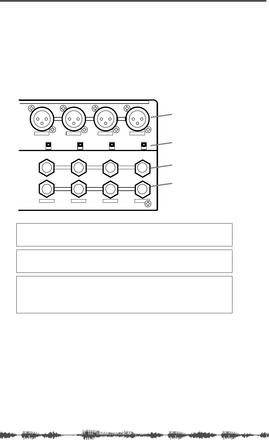
Input Channels
60
VM200 User’s Guide
Input Channels 1–4
There are two sets of analog connectors for Input Channels 1 - 4.
The “A” set accepts XLR-type inputs (balanced); the “B” set accepts
phone jacks (balanced or unbalanced).
The XLR connectors are XLR-3-32-type inputs. The phone jacks are
1/4-inch TRS-type.
Both XLR and phone jack inputs accept a nominal input range of
–60 dB to +10 dB.
Note:
Before you set the INPUT A/B switch for input channels 1-4, lower
the corresponding TRIM control to the minimum, or you will hear a clicking
noise.
Note:
Before you turn on phantom power, lower the TRIM control for the
corresponding input channel to the minimum, or turn off the power to the
VM200.
Note:
Turn off the corresponding phantom power switch before you connect
a dynamic microphone; otherwise, you may damage the microphone. If you
turn on the power to the VM200 while the input channel’s phantom power
switch is turned on, the VM200 displays a warning message: “Warning! +48V
SW ON!”
1234
AAA
1234
+48V OFF
ON +48V OFF
ON +48V OFF
ON +48V OFF
ON
INPUT
INSERT
B
INSERTINSERT
BB
phantom power switch
XLR inputs
phone jack inputs
inserts
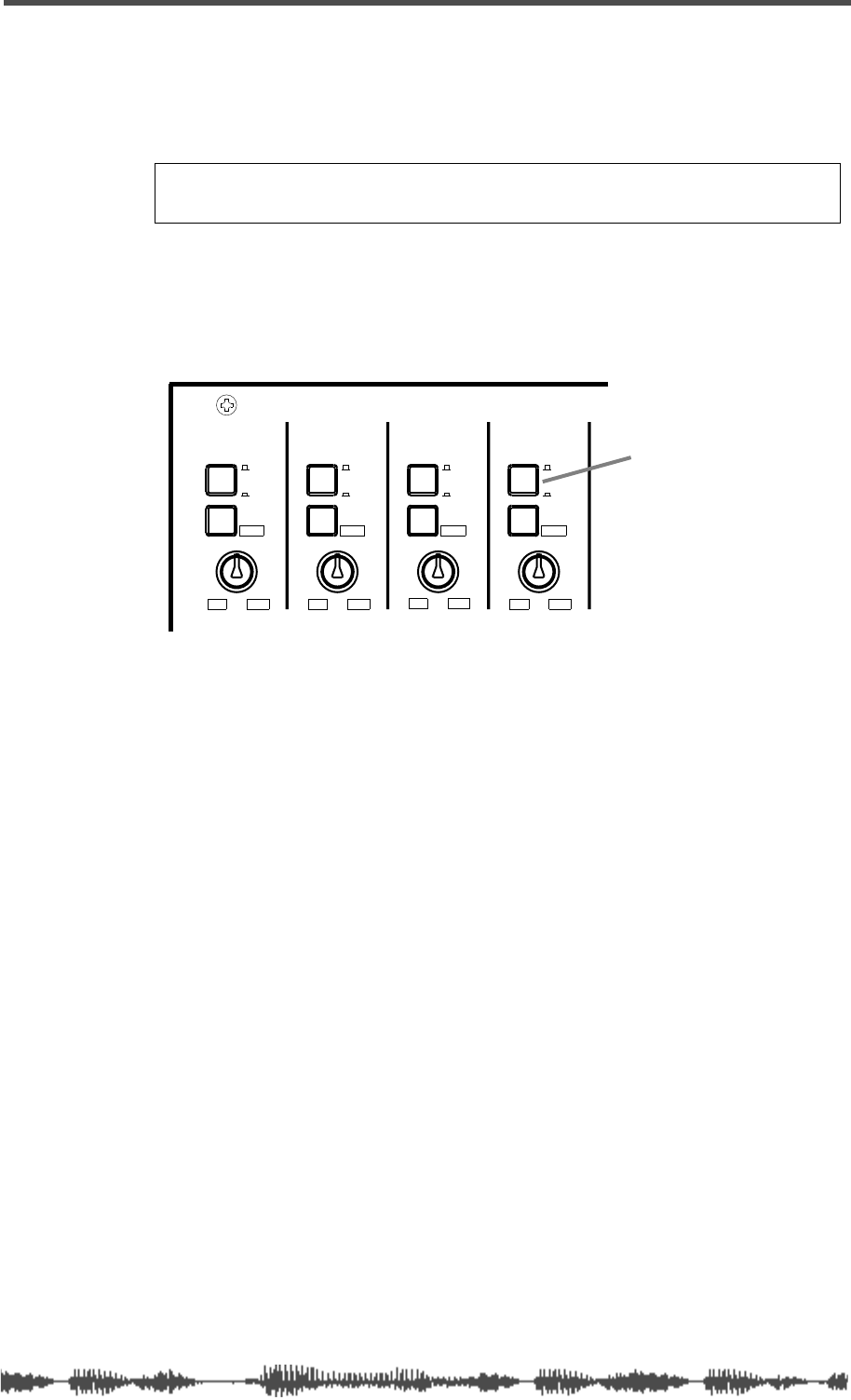
Phantom Power for Input Channels 1–4
VM200 User’s Guide
61
Phantom Power for Input Channels 1–4
The VM200 supplies optional phantom power (+48 V) to the XLR con-
nectors. You can turn the phantom power on or off using the switches
on the rear panel as shown in the figure above.
Specify the connector you wish to use by pressing (or not pressing) the
A/B input selectors on the top panel (shown in the figure below). The
A setting (unpressed) selects the XLR input connector; the B setting
(depressed) selects the phone jack input connector.
Input Channels 5–8
Input channels 5–8 accept only unbalanced phone jacks. (These con-
nectors do not accept XLR inputs or balanced analog inputs.)
For more information, see “Rear Panel” on page 38.
Input Channels 9–16
In addition to the analog signals you can input to channels 1
through 8, you can assign digital ADAT inputs to channels 9-16.
Refer to “Digital Connections” on page 159 for more information.
Input Channels 17–20
Input channels 17–20 are used for internal effect returns from the
EFF1 or EFF2 effects processor.
Caution:
Turn on the phantom power only after you connect a balanced XLR
component (such as a condenser microphone) to the XLR input connector.
INPUT 4INPUT 3INPUT 2INPUT 1
PAD
26dB
A
B
PAD
26dB
A
B
PAD
26dB
A
B
PAD
26dB
A
B
-16 -60
+10 -34
-16 -60
+10 -34
-16 -60 -16 -60
TRIMTRIMTRIMTRIM
+10 -34 +10 -34
A/B Input selector
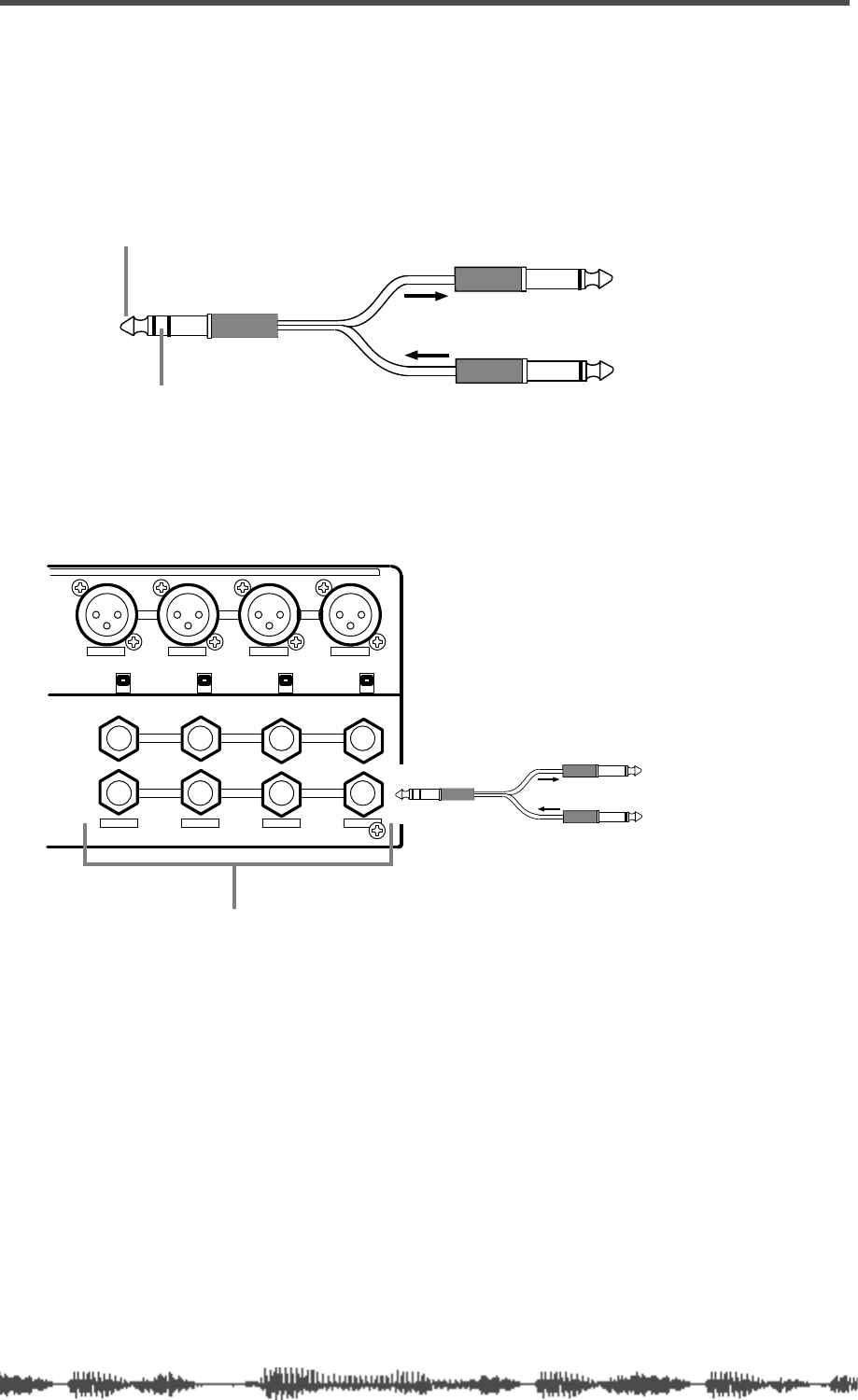
Input Channels
62
VM200 User’s Guide
Insert Channels 1–4
You can use a Y-shaped insert cable to connect the VM200 to an
external effects processor. The signal flows out of the VM200 Insert
connector, into and out of the effects processor, and back into the
VM200 via the insert cable.
The Insert connectors allow you to insert a signal into the signal
chain after the PAD switches and TRIM knobs.
Tip (Send)
Ring (Return)
from VM200 to Effects processor
from Effects processor to VM200
1234
AAA
1234
+48V OFF
ON +48V OFF
ON +48V OFF
ON +48V OFF
ON
INPUT
INSERT
B
INSERTINSERT
BB
INSERT connectors 1-4
to FX
from FX
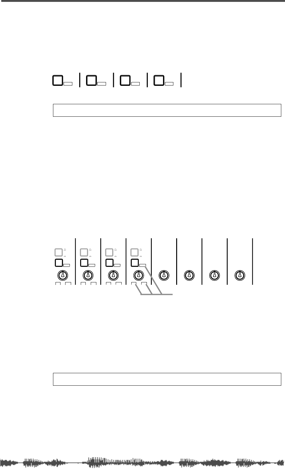
Pad Switches (Input channels 1–4)
VM200 UserÕs Guide
63
Pad Switches (Input channels 1–4)
Input channels 1 through 4 feature 26 dB Pad switches that attenu-
ate the input signal by 26 dB.
This allows the input preamp to work with hot, high-level signals,
such as those from a snare drum microphone.
TRIM Controls
You can adjust the gain of the input channel preamps on input chan-
nels 1 through 4 by using the Trim controls. Your goal is to optimize
the input signal level to achieve the best signal-to-noise ratio.
Keep a close eye on the level meters while adjusting the Trim controls.
In general, set the levels as high as possible without peaking (actually,
it’s okay if the level
occasionally
peaks a little). If you set the level too
high, the signal may distort and or clip. If it’s set too low, the output
signal may sound thin or noisy.
The Trim controls have an input sensitivity of –16 dB to –60 dB,
which is appropriate for many microphones. However, you can press
one of the Pad switches for channels 1–4 to reduce the input sensitiv-
ity for that channel to the range of +10 to –34 dB. This works well for
“hot” microphone signals.
The Trim controls on input channels 5–8 have a gain range of –10 dB
to –50 dB. This works well with line-level signals.
PAD
26dB
PAD
26dB
PAD
26dB
PAD
26dB
Note: Pad switch settings are not stored in Scene Memory.
INPUT 4INPUT 3INPUT 2INPUT 1
PAD
26dB
PAD
26dB
PAD
26dB
A
B
A
B
A
B
A
B
PAD
26dB
-16 -60
+10 -34
-16 -60
+10 -34
-16 -60 -16 -60
TRIMTRIMTRIMTRIM TRIM
-10 -50
TRIM TRIM TRIM
-10 -50 -10 -50 -10 -50
INPUT 5 INPUT 6 INPUT 7 INPUT 8
+10 -34 +10 -34
VM200 uses “boxed” values
when Pad switch is depressed.
Note: Trim control settings are not stored in Scene Memory.
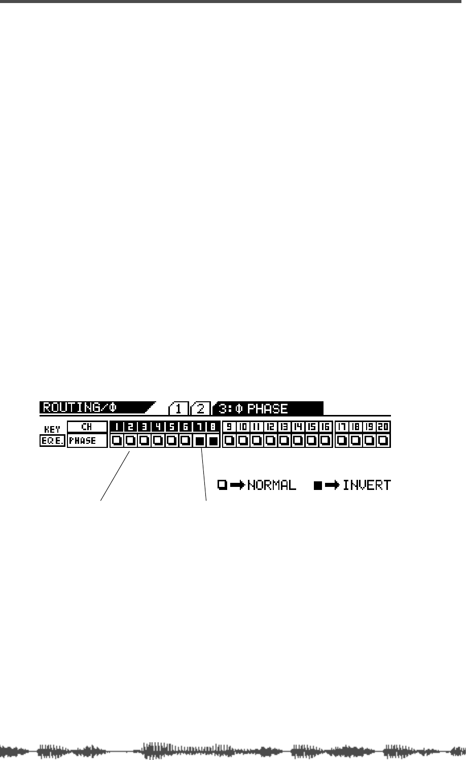
Input Channels
64
VM200 User’s Guide
Inverting the Input Phase
“Phase” concerns the timing of two different signals. A pair of stereo
speakers can operate “in phase” or “out of phase.” If the drivers in
the left and right speakers move in and out at the same time, in per-
fect concert with one another, the speakers are “in phase.” If they
are out of sync, they are “out of phase.” Out-of-phase speakers tend
to produce a weak stereo image and low bass output.
Phase is often represented by this symbol:
∅.
On the VM200, you can invert the phase for channels 1–20. First you
access the
PHASE
function page, then press an
[EQ EDIT]
key to turn
phase inversion on or off. A light indicator on the display means
phase is normal (off) for that channel; a dark (highlighted) indicator
means phase is inverted (on).
You can use the phase inversion software switches to compensate for
balanced cables or microphones that may have been wired incor-
rectly, or at any time you wish to invert the phase of a channel to pre-
vent signal cancellation.
1.
Press the
[ROUTING/PHASE]
key repeatedly to display the
3:
∅
PHASE
function page.
The
[ROUTING/PHASE]
key and the
[EQ EDIT]
keys for all selectable
channels start to flash (indicating their availability).
The
3:
∅
PHASE
function page includes a 1-by-20 matrix that indi-
cates whether the phase is normal or reversed for each channel.
2.
Press a Page Select key to select the target channel layer,
then press the
[EQ EDIT]
key for any channel to reverse its
phase.
The
[EQ EDIT]
key lights up if you turn phase inversion on.
Even when channels are configured as stereo pairs, their phase
switches can be set independently.
3.
Press the
[EXIT]
key or the
[CHANNEL/METER]
key.
The VM200 displays the
CHANNEL EDIT
function page.
Indicates Phase is reversed.
Indicates phase is normal.

Input Channel EQ
VM200 User’s Guide
65
Input Channel EQ
You can apply EQ to channels 1—16 using the four-band parametric
equalizer. For more information on using the equalizer, see “EQ” on
page 75.
Muting Channels
To mute a channel, use the Page Select keys to select the desired
channel layer, then make sure the channel’s
[ON]
key is turned off.
If channels are linked as a stereo pair (see “Pairing Channels” on
page 68) you can use either channel’s
[ON]
key to turn the pair off (or
on).
You can also group input channels into Mute groups and control them
as one, using a single
[ON]
key. (See “Grouping Mute Channels” on
page 68.)
Setting Channel Levels
You control input channel levels using the faders.
If it is not already selected, select the desired channel layer using a
Page Select key, then press the channel’s
[ON]
key.
The VM200 features seven Fader Modes. The faders control different
functions and parameters depending on the current Fader Mode.
You can select a Fader Mode by pressing one of the keys in the Fader
Mode section, such as
[AUX1]
,
[EFF2]
,
[CHANNEL]
, etc. (See “Faders” on
page 32 for more information about Fader Modes.)
If channels are linked as a stereo pair or group, you can set the chan-
nel level for the pair or group using any fader in the pair or group. For
more information, see “Pairing Channels” on page 68.
Panning Input Channels
Use the eight panpot rotary controls to pan the signal between the
left and right channels of the stereo output.
1.
Make sure that the
[CHANNEL/METER]
key is lit. If not, press it
to turn it on.
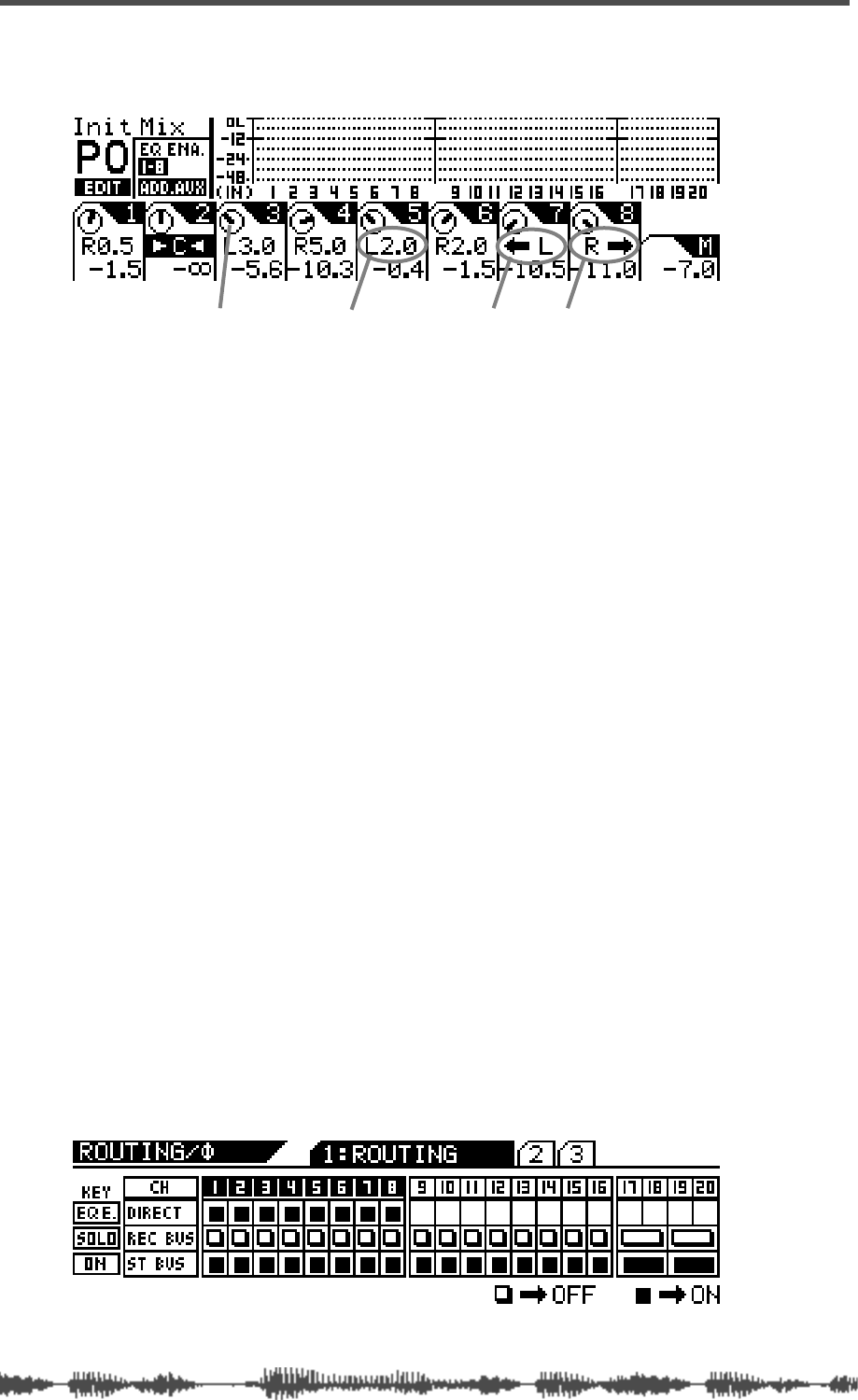
Input Channels
66
VM200 User’s Guide
The VM200 displays the
CHANNEL EDIT
function page.
2.
Use the Page Select keys to select the target channel layer.
3.
Use the panpot rotary controls to make the pan settings.
The display shows a dial icon for each channel that visually indi-
cates the pan position. The display also includes numerical val-
ues—such as L2.0 or R3.7—that provide precise pan position
data.
If you pan hard right or hard left (that is, fully right or left), the
numerical value changes to a left or right arrow to indicate that
the maximum has been reached.
The pan settings range from L10.0 to R10.0 in increments of 0.5
(although you’ll never see R10.0 or L10.0 indications, because
these settings are the maximum value and are replaced by the
arrow).
Routing Input Channels
You can control input channel routing by using the on/off software
switches on the
ROUTING
function page.
The
ROUTING
function page includes switches that can route channels
1–20 to the Rec Buss and Stereo Buss, and channels 1–8 to the
ADAT Direct outputs. (You cannot route channels 9–20 to the ADAT
Direct outs.)
1.
Press the
[ROUTING/PHASE]
key to display the
1:ROUTING
func-
tion page.
The [EQ EDIT], [SOLO], and [ON] keys start to flash (indicating
their availability). The [ROUTING/PHASE] key also flashes.
hard left hard rightpanpot icon numeric pan value
Monitoring and Soloing Input Channels
VM200 User’s Guide
67
2.
Use the Page Select keys to select the target channel layer.
3.
Press the
[EQ EDIT]
,
[SOLO]
, or
[ON]
key that represents the
desired routing for the target channel.
See the following table:
When you press an
[EQ EDIT]
,
[SOLO]
, or
[ON]
key, the key lights up
and the corresponding indicator on the display turns dark (high-
lighted). A light empty indicator means the routing is not selected
(off).
If channels are configured as stereo pairs, their Routing switches
are also linked. (For more information on pairing channels, see
“Pairing Channels” on page 68.)
4.
Press the
[EXIT]
key or the
[CHANNEL/METER]
key to return to
Channel Edit mode.
Monitoring and Soloing Input Channels
For information on monitoring input channels, see “Monitoring Sig-
nals” on page 97
Feeding Outputs
REC Buss Out
You can route input channels 1–20 to the Rec Buss outs. See “Using
the REC BUSS OUT” on page 112 for more information.
ST Buss Out
You can route input channels 1–20 to the Stereo Buss outs. See
“Using the ST BUSS OUT” on page 110 for more information.
AUX Sends
You can route input signals to Aux 1, 2, 3, or 4 by pressing the
[AUX1]
,
[AUX2]
,
[AUX3]
, or
[AUX4]
key and raising the corresponding fader. (You
can use Aux 3 and 4 when ADD. AUX mode is turned on.) You can
also configure input channel sends as either pre-fader or post-fader.
See “Using the AUX Sends” on page 115 for more information.
KEY TARGET ROUTING
EQ EDIT
ADAT DIRECT OUT
SOLO
REC BUS
ON
STEREO BUS
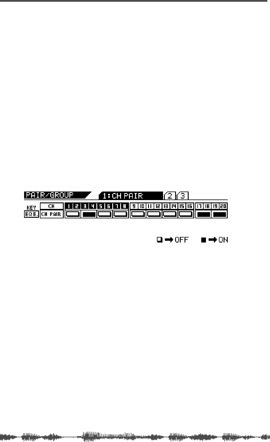
Input Channels
68
VM200 User’s Guide
Digital Outs
You can select input channels 1–20 as sources for the digital outs.
See “Digital Connections” on page 159 for more information.
Pairing Channels
You can create up to ten pairs of channels from input channels 1–20
to facilitate stereo signal processing.
You can pair only adjacent odd/even channels, such as 1 and 2, 5
and 6, etc. (You cannot pair non-adjacent channels, such as 2 and 7,
or even/odd pairs such as 4 and 5.)
The following parameters are linked when input channels are paired:
EQ,
[ON]
,
[SOLO]
, and
[EQ EDIT]
keys, faders, Aux sends, Effect sends,
Pre/post settings, and Routing switches.
1.
Press the
[PAIR/GROUP]
key to display the
1:CH PAIR
function
page.
The [PAIR/GROUP] key and the [EQ EDIT] keys start to flash.
2.
If the appropriate channel layer is not yet selected, press a
Page Select key to select the desired channel layer.
The selected Page Select key lights up.
3.
Press the
[EQ EDIT]
key for one of the channels you wish to
pair.
The
[EQ EDIT]
keys for the channel pair light up. The display high-
lights the indicator for the channel pair.
You can press a corresponding
[EQ EDIT]
key to cancel any stereo
pair.
4.
Press the
[EXIT]
key or the
[CHANNEL/METER]
key to return to
Channel Edit mode.
Grouping Mute Channels
You can group channels 1-20 into mute groups. This enables you to
mute several channels simultaneously by pressing a single
[ON]
key.
For example, you may wish to turn all the channels devoted to a cho-
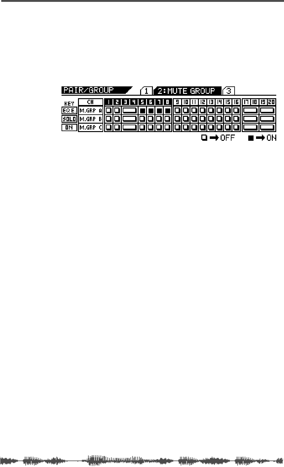
Grouping Faders
VM200 User’s Guide
69
rus or drum kit on and off simultaneously during mixdown. You can
group these channels into a mute group.
Three groups are available: Mute Groups A, B, and C.
1. Press the [PAIR/GROUP] key twice to display the 2:MUTE GROUP
function page.
THE [PAIR/GROUP] key and all [EQ EDIT], [SOLO], and [ON] keys
flash.
2. Press the [EQ EDIT] keys for the channels you wish to add to
Mute Group A.
The [EQ EDIT] keys light up and the corresponding indicators on the
display turn on (highlight).
In the example above, channels 5, 6, 7, and 8 are assigned to Mute
Group A. (No other channels are assigned to a Mute group.)
3. Press the [SOLO] keys for the channels you wish to add to
Mute Group B.
The [SOLO] keys light up and the corresponding indicators on the
display turn on (highlight).
4. Press the [ON] key for the channels you wish to add to Mute
Group C.
The [ON] keys light up and the corresponding indicators on the dis-
play turn on (highlight).
5. To remove a channel from the mute group, press the corre-
sponding [EQ EDIT], [SOLO], or [ON] key.
The key resumes flashing and the corresponding display indicator
turns off.
6. Press the [EXIT] key or the [CHANNEL/METER] key to return to
Channel Edit mode.
Grouping Faders
You can group faders 1-8 into Fader groups. This enables you to con-
trol several faders simultaneously using only one fader.
Three groups are available: Mute Groups A, B, and C.
1. Press the [PAIR/GROUP] key repeatedly to display the 3:FADER
GROUP function page.
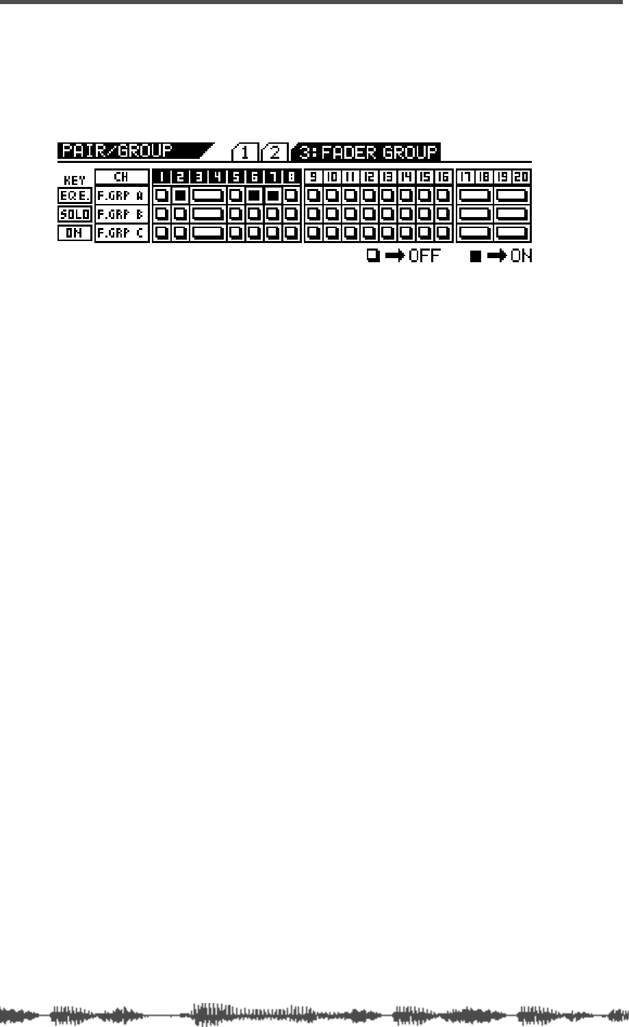
Input Channels
70 VM200 User’s Guide
THE [PAIR/GROUP] key and all [EQ EDIT], [SOLO], and [ON] keys
start to flash.
In the following example, channels 2, 6, and 7 are assigned to
Fader Group A. (No other channels are assigned to Fader
Groups.)
2. Press the [EQ EDIT] keys for the faders you wish to add to
Fader Group A.
The [EQ EDIT] keys light up and the corresponding indicators on the
display turn on (highlight).
3. Press the [SOLO] keys for the faders you wish to add to Fader
Group B.
The [SOLO] keys light up and the corresponding indicators on the
display turn on (highlight).
4. Press the [ON] keys for the faders you wish to add to Fader
Group C.
The [ON] keys light up and the corresponding indicators on the dis-
play turn on (highlight).
5. To remove a fader from the fader group, press the correspond-
ing [EQ EDIT], [SOLO], or [ON] key.
The key resumes flashing and the corresponding display indicator
turns off.
6. Press the [EXIT] key or the [CHANNEL/METER] key to return to
Channel Edit mode.
Viewing Input Channel Settings
The CHANNEL VIEW function page enables you to view the settings for
any input channel.
You cannot adjust any parameters on the CHANNEL VIEW function page.
(If you try to adjust the pan setting, the VM200 displays the CHANNEL
EDIT function page.)
1. Press the [CH VIEW] key to display the 1:CH VIEW function page.
The [CH VIEW] key and the [EQ EDIT] keys for all viewable channels
flash. The selected Page Select key lights up; unselected Page Select
keys flash.
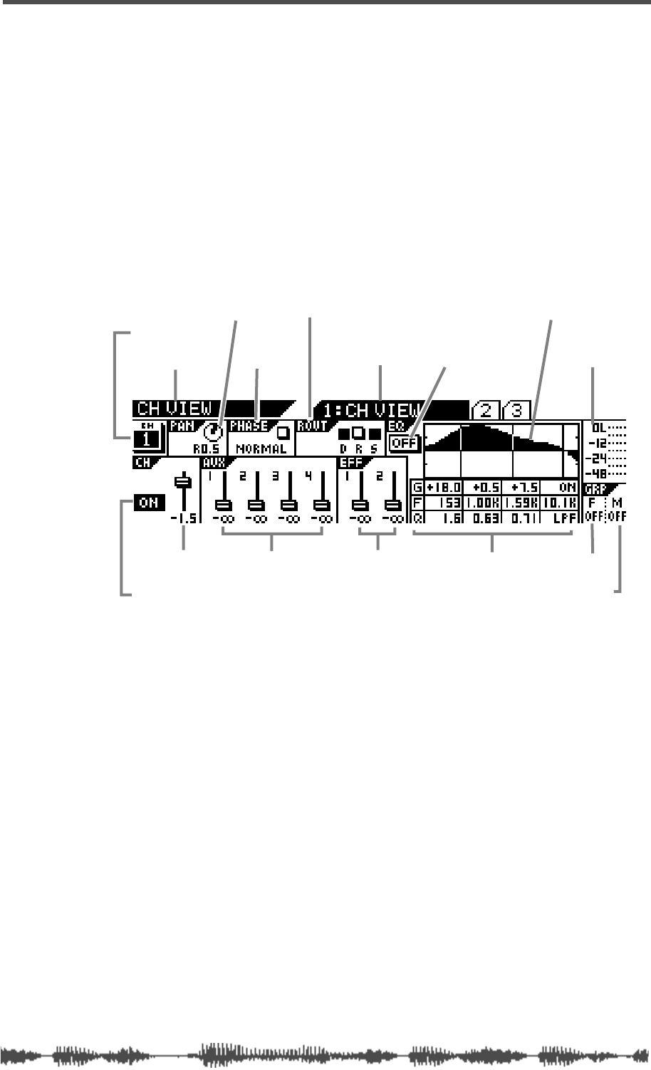
Viewing Input Channel Settings
VM200 UserÕs Guide
71
2.
Press the appropriate Page Select key to select the desired
channel layer.
The selected Page Select key lights up; unselected Page Select keys
continue to flash.
3.
Press the
[EQ EDIT]
key for the target channel.
The selected
[EQ EDIT]
key lights up. The number of the selected
channel appears in the upper left portion of the
CHANNEL VIEW
func-
tion page.
The following illustration describes the components of the
CHANNEL
VIEW
function page.
4.
Press the
[EXIT]
key or the
[CHANNEL/METER]
key to return to
Channel Edit mode.
function page title sub-page title
channel number
[ON] key status
channel fader level aux send levels effect send levels
routing (Direct, Rec buss, St buss)
EQ on/off
EQ curve graphic
EQ numeric settings
(gain, freq, Q)
level meter
fader group
mute group
phase
channel pan setting
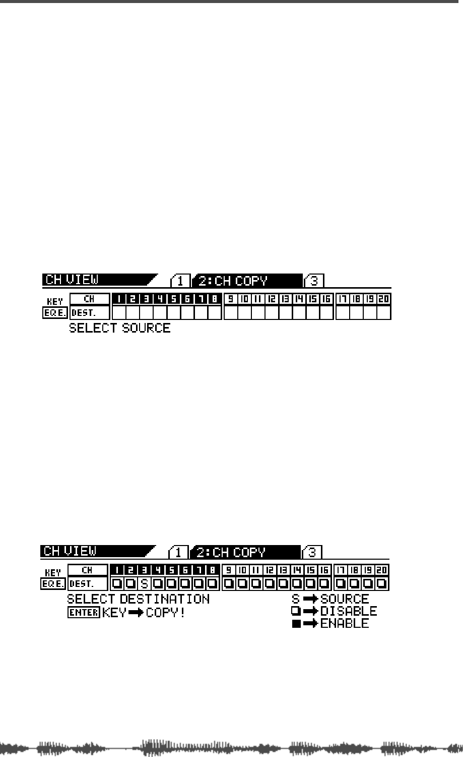
Input Channels
72 VM200 User’s Guide
Copying Channel Settings
You can use the Channel Copy function to copy input channel set-
tings from one channel to another.
The CHANNEL COPY function page features a 1-by-20 matrix that
enables you to select one source channel, and enable or disable the
other channels as copy destinations.
The selected source channel is marked by an “S.” A highlighted indi-
cator marks the channels targeted as copy destinations. A dark indi-
cator means the channel is not selected (disabled) as a copy
destination.
1. Press the [CH VIEW] key twice (from start of cycle) to display
the 2:CH COPY function page.
The [CH VIEW] key and the [EQ EDIT] keys for all channels flash. The
selected Page Select key lights up; the unselected Page Select keys
flash.
2. Press the appropriate Page Select key to select the desired
channel layer.
The selected Page Select key lights up; unselected Page Select keys
continue to flash.
3. Press the [EQ EDIT] key for the copy source channel.
You can select only one source channel to copy at a time.
The selected [EQ EDIT] key lights up. The CHANNEL COPY function page
marks the source channel with an “S” and prompts you to select a
destination channel.
4. Press the appropriate Page Select key to specify the channel
layer, then press the [EQ EDIT] key of the copy destination
channel(s).
You can select multiple channels as destinations.
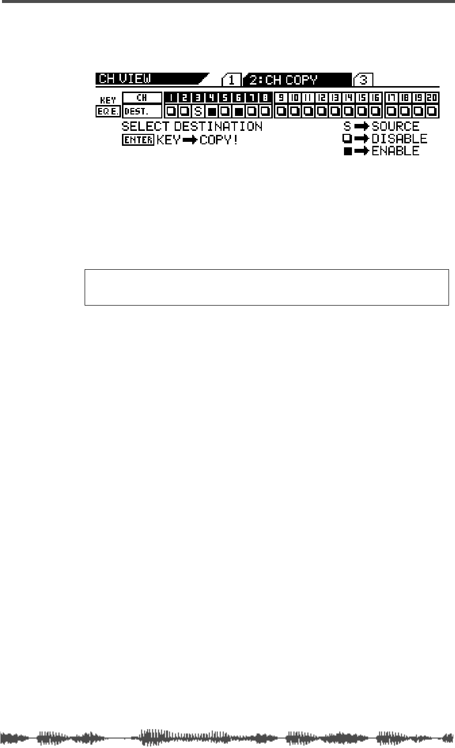
Copying Channel Settings
VM200 User’s Guide 73
The selected [EQ EDIT] key(s) light up. The CHANNEL COPY function
page highlights (enables) the selected destination channel(s) as fol-
lows.
5. Press the [ENTER] key to execute the copy operation.
The CHANNEL COPY function page flashes the word “COMPLETE!” on
the display for a few seconds, and the VM200 displays the first CH
COPY function page.
6. Press the [EXIT] key or the [CHANNEL/METER] key to return to
Channel Edit mode.
Note: Even if channels are paired, you can copy to and from each
of the paired channels independently.

Input Channels
74 VM200 User’s Guide
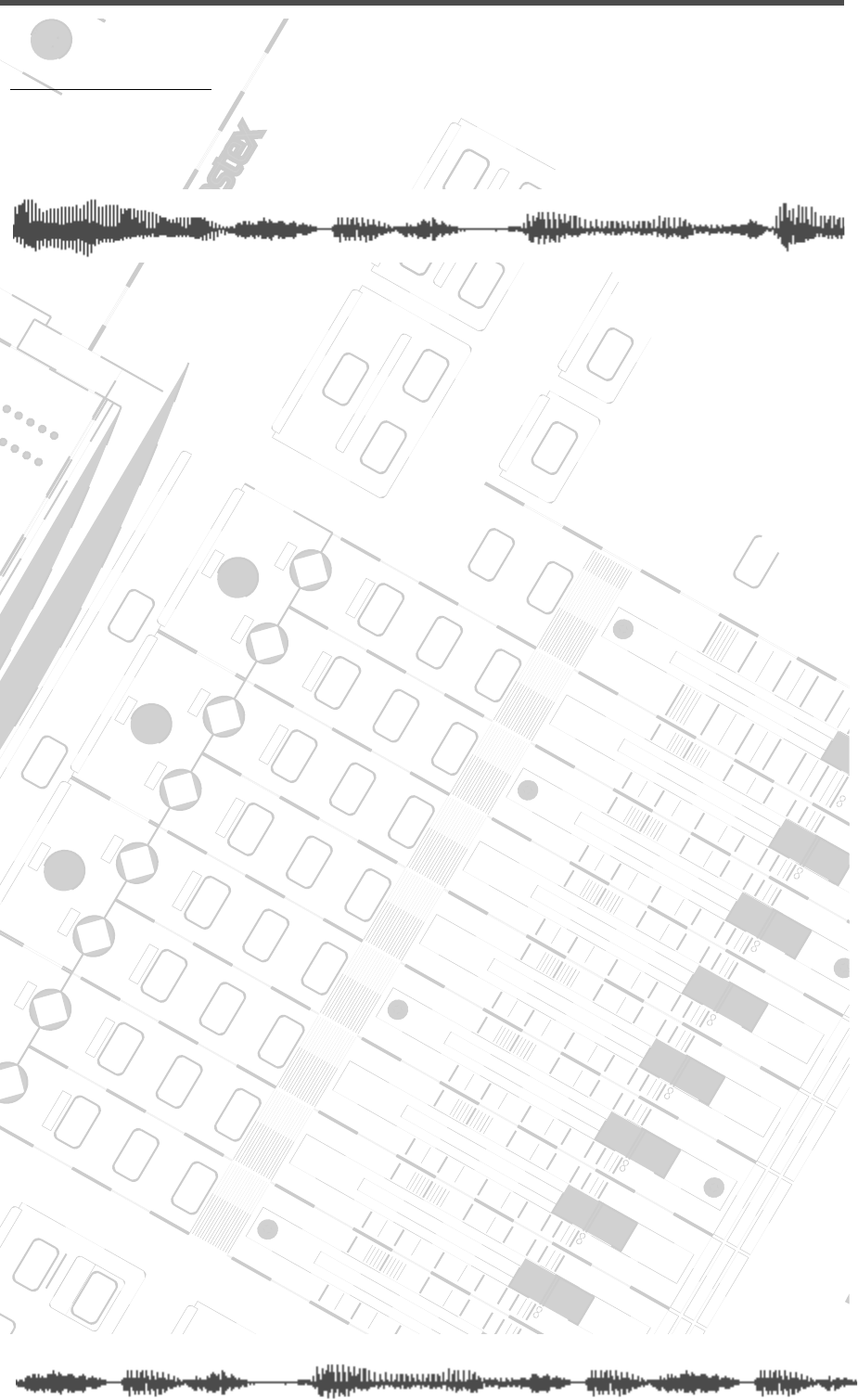
DIGITAL RECORDING MIXER
VM200
REC BUSS
EFF EDITSELECTED EQ
EQ/HI
EQ/HI-MIDEQ/LO-MID
+10
0
-10
-20
-30
-40
-
+10
0
-10
-20
-30
-40
-
+10
0
-10
-20
-30
-40
-
+10
0
-10
-20
-30
-40
-
+10
0
-10
-20
-30
-40
-
+10
0
-10
-20
-30
-40
-
+10
0
-10
-20
-30
-40
-
GAIN
FREQ
PAN
Q
PAN
ON ON ON ON ON ON ON
SOLO SOLO SOLO SOLO SOLO SOLO SOLO
EQ EDIT EQ EDIT EQ EDIT EQ EDIT EQ EDIT EQ EDIT EQ EDIT EQ EDIT
SOLO
ON ON
SOLO
EQ LIBRARY
STORERECALL
EQ ON
EFF LIBRARY
STORERECALL
EFF2EFF1
RECALLSOLO
EXIT
14
6
13
5
12
4
11
3
2019
FREQ QFREQ Q
Q
GAINGAIN
9-16 ADAT IN 17-20 EFF RTN
P
AGE SELECT
GROUP
PAIR/
METER
CHANNEL/
MIN MAX
+10
0
1
0
1
0
0
-10
-20
-30
-60
-
-40
MMC SEND
PANPANPANPANPANPAN
-40
-36
-24
-18
1212
ST BUSS/SOLO
L R
VM200 User’s Guide
75
CHAPTER 5
EQ
About This Chapter
This chapter explains how to use the VM200 four-band parametric
equalizer (EQ) and how to edit, recall, and store EQ settings.
Chapter Contents
Equalizers (EQ). . . . . . . . . . . . . . . . . . . . . . . . . . . . . . . . . . 76
Adjusting the EQ . . . . . . . . . . . . . . . . . . . . . . . . . . . . . . . . 77
EQ Enabling Channels . . . . . . . . . . . . . . . . . . . . . . . . . . . . 80
Bypassing the EQ. . . . . . . . . . . . . . . . . . . . . . . . . . . . . . . . 80
Resetting the EQ . . . . . . . . . . . . . . . . . . . . . . . . . . . . . . . . 81
EQ Library . . . . . . . . . . . . . . . . . . . . . . . . . . . . . . . . . . . . . 83
EQ Preset Library List . . . . . . . . . . . . . . . . . . . . . . . . . . 83
Recalling EQ Programs. . . . . . . . . . . . . . . . . . . . . . . . . . . . 84
Storing EQ Programs . . . . . . . . . . . . . . . . . . . . . . . . . . . . . 86
Editing EQ Program Titles . . . . . . . . . . . . . . . . . . . . . . . . . 88
Copying EQ Settings. . . . . . . . . . . . . . . . . . . . . . . . . . . . . . 90
EQ Preset Library Parameters. . . . . . . . . . . . . . . . . . . . . . . 92

EQ
76
VM200 User’s Guide
Equalizers (EQ)
The VM200 features a four-band parametric equalizer for input
channels 1–16.
The four-band equalizer subdivides the audio spectrum into LO,
LO-MID, HI-MID, and HI frequency ranges. Each of the four bands
includes rotary controls for Gain, Frequency, and Q.
The LO-MID and HI-MID bands use parametric EQ. The LO band can
function as an HPF, shelving, or parametric EQ; the HI band can
function as an LPF, shelving, or parametric EQ.
The Gain control adjusts the amount of increase in a signal, generally
measured in decibels (dB).
The Frequency control specifies the number of cycles-per-second of
a waveform (in our case, soundwaves).
The Q control adjusts the sharpness of the EQ peak response.
The LO band Q can function as a high-pass filter (HPF), and HI band
Q can function as a low-pass filter (LPF).
A low-pass filter (LPF) rejects signals above a certain cut-off fre-
quency while passing lower-frequency signals through.
A high-pass filter (HPF) rejects signals below a certain cut-off fre-
quency while passing higher-frequency signals through.
In a shelving-type (SHLV) EQ, the boosted or cut-off frequencies form
a shelf-shape on a frequency response curve. A high-frequency shelf
affects signals at and higher than the specified frequency; a low fre-
quency shelf affects signals at and higher than the specified fre-
quency.
The
EQ EDIT
function page displays a graphic EQ response curve for
channels 1 - 16. The EQ response curve provides visual feedback to
help you shape the EQ, while the numerical read-outs ensure
extremely accurate settings that you can store in the EQ Library and
later recall.
The EQ Library consists of 50 Preset programs and 50 User pro-
grams. You can store EQ settings into User programs, or into Scene
Memory along with all other mix settings. You can also recall EQ set-
tings from the Preset programs or User programs, or from Scene
Memory along with all other mix settings.
The Presets are a special collection of EQ settings that can be useful
in a variety of situations. See “EQ Preset Library List” on page 83.
You can also use the Presets as templates that you can customize to
create your own EQ settings. You can name and store up to 50 of your
favorite EQ settings as User programs.
If channels are configured as a stereo pair, their EQs are linked.
The EQ parameters and response curve for input channels 1 through
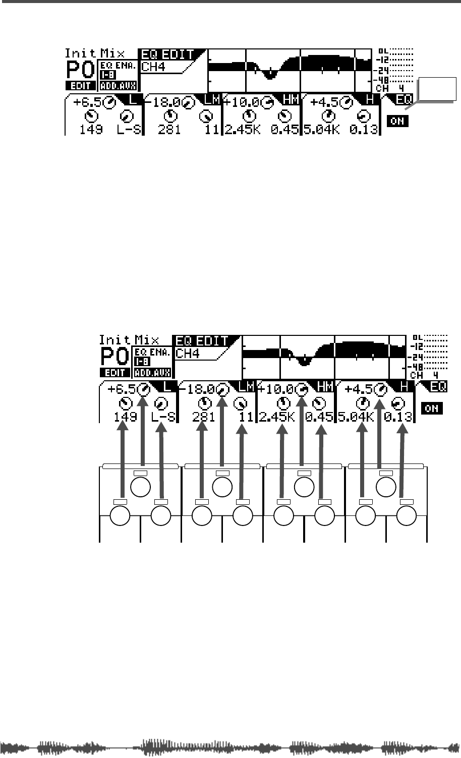
Adjusting the EQ
VM200 User’s Guide
77
16 appear on the
EQ EDIT
function page, as shown below:
Adjusting the EQ
You can adjust the EQ for each of the four bands using three rotary
controls: Gain, Freq, and Q. These three EQ controls form a triangu-
lar shape on the top panel of the VM200.
The LCD display also features four sets of three circular knob icons.
Each set of three is arranged in a triangle that corresponds to the
hardware EQ rotary controls. (That is, Gain is on top, Freq is on the
lower-left, and Q is on the lower-right.)
Note that in EQ Edit mode, the Pan rotary controls adjust Freq and Q.
1.
Make sure that the
[CHANNEL/METER]
key is lit. Otherwise,
press it to turn it on.
2.
Press a Page Select key to specify a channel layer, such as
[1-8
ANALOG IN]
key.
The selected Page Select key lights up red.
3.
Press the
[EQ EDIT]
key for the channel whose EQ you wish to
edit.
EQ On
indicator
EQ/HI
EQ/HI-MIDEQ/LO-MIDEQ/LO
GAIN
FREQ
PAN
Q
PAN
FREQ QFREQ Q
FREQ Q
GAINGAINGAIN
PANPANPANPANPANPAN
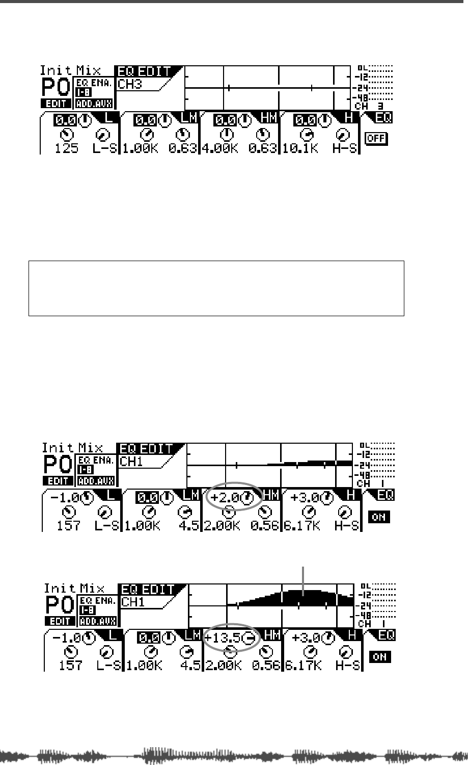
EQ
78
VM200 User’s Guide
The selected
[EQ EDIT]
key lights up and the VM200 displays the
EQ EDIT
function page.
4.
Press the
[EQ ON]
key in the Selected EQ section to turn it on.
The
[EQ ON]
key lights up, and the VM200 turns on the EQ for the
selected channel.
The EQ On/Off indicator in the lower-right corner of the display
shows “On” to indicate that the EQ is turned on for the specified
channel.
5.
Use the rotary controls (Gain, Freq, and Q) to adjust the Fre-
quency, Gain, and Q parameters.
The display shows a graphic frequency response curve.
You can watch a bell-shaped curve swell as you increase the gain,
or drop below the mid-line when you reduce the gain.For exam-
ple, watch the response curve swell as you raise the EQ/HI-MID
Gain, as illustrated in figures A and B below.
Note:
Be aware that the EQ may not turn on for certain channels
if the EQ Enable parameter setting is incorrect. The EQ Enable
parameter appears on the
CURRENT SCENE STATUS
function page. See
“EQ Enabling Channels” on page 80 for more information.
A
B
the response curve swells when Gain is raised
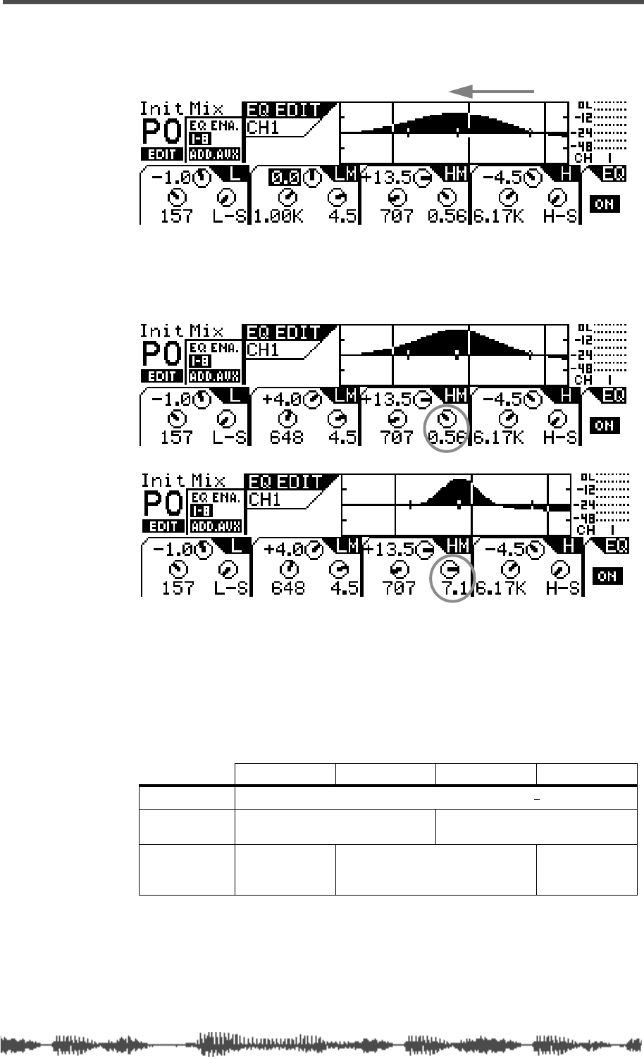
Adjusting the EQ
VM200 UserÕs Guide
79
If you lower the Freq, the soft bell-shaped curve in Figure B would
move to the left, as illustrated in Figure C:
In Figures D and E below, notice how the frequency range is
reduced and the response curve sharpens and narrows as the
EQ/HI-MID Q value is raised.
If you select HPF or LPF for LO band Q or HI band Q respectively,
the Gain rotary control for LO EQ or HI EQ functions as the
On/Off switch.
The following table shows the VM200 EQ specifications.
Lo Lo-Mid Hi-Mid Hi
Gain (G)
–18.0 dB to +18.0 dB (0.5 dB steps)
1
1. When the LO and HI EQ bands are configured as HPF and LPF, their gain controls
function as filter on and off switches.
Frequency (F)
20.3 Hz–4.00 kHz
(240 steps per 1/24 octave) 500Hz–20.3kHz
(240 steps per 1/24 octave)
Q
HPF, 0.1–20
(45 steps),
Lo-shelf
0.1–20
(45 steps)
LPF, 0.1–20
(45 steps),
Hi-shelf
C
bell moves left
D
E
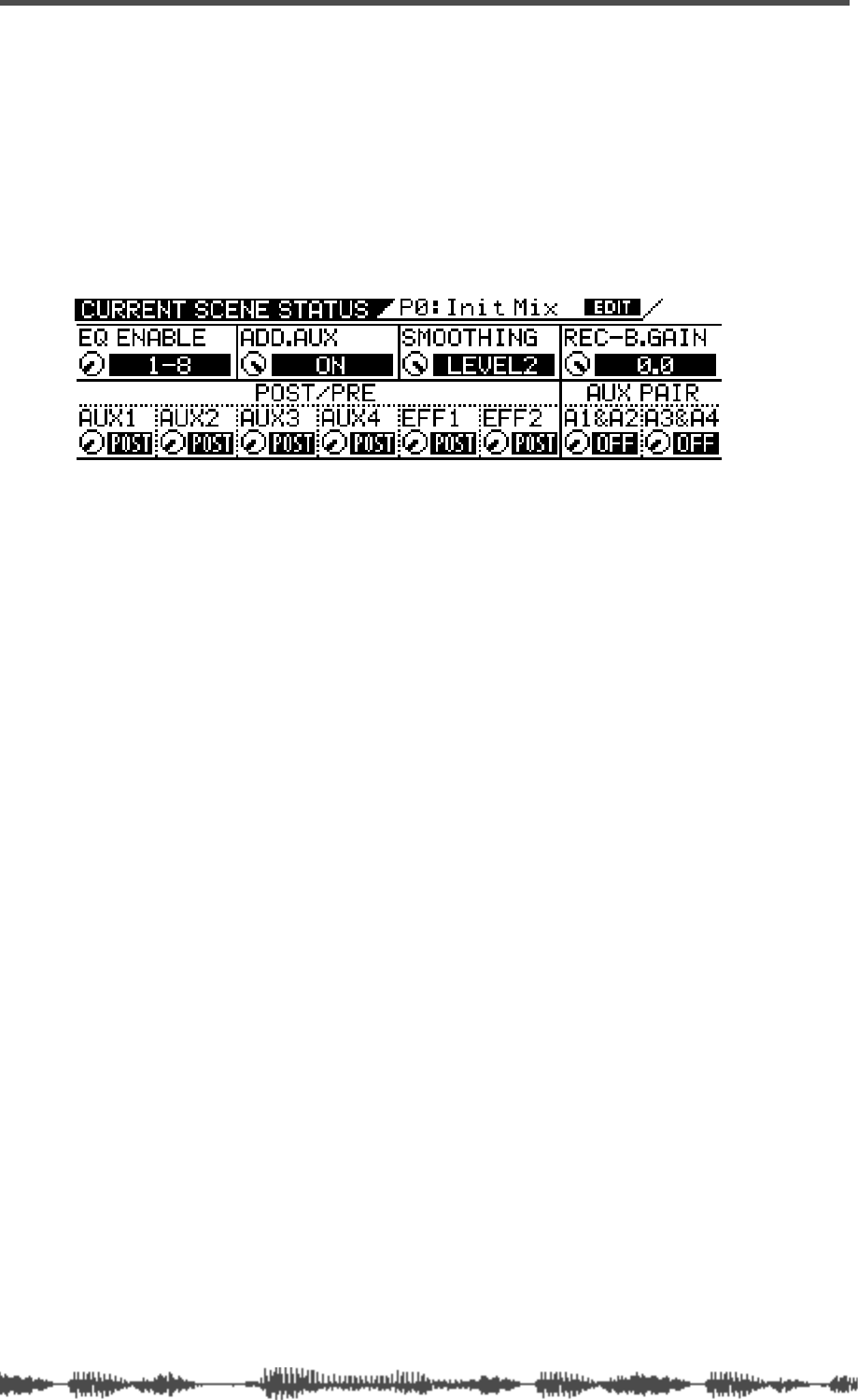
EQ
80
VM200 User’s Guide
EQ Enabling Channels
You can enable the EQ for three groups of channels: 1–8, 9–16, or
1–16.
(The default setting enables the EQs for channels 1–8.)
1.
Press the
[CURRENT SCENE STATUS]
key.
The
CURRENT SCENE STATUS
function page appears. Notice the EQ
Enable parameter in the upper-left corner.
2.
Turn the channel 1/2 Gain rotary control to select 1–8, 9–16,
or 1–16 for the EQ Enable parameter.
The selected value flashes.
3.
Press the
[ENTER]
key to confirm your selection.
The VM200 displays the selected value for the EQ Enable param-
eter.
4.
Press the
[EXIT]
key or the
[CHANNEL/METER]
key to return to
Channel Edit mode.
Bypassing the EQ
You can turn a channel’s EQ on or off (bypass) using the
[EQ ON]
key.
While the target channel is selected (by pressing a Page Select key
and the channel’s
[EQ EDIT]
key), press the
[EQ ON]
key to toggle
between EQ On and Off.
When the EQ is on, a highlighted “ON” indicator appears in the
lower-right corner of the
EQ EDIT
function page. If the EQ is bypassed,
“OFF” appears in the same location.
1.
Press the
[1–8 ANALOG IN]
or
[9–16 ADAT IN]
Page Select key to
select a channel layer.
The selected Page Select key lights up.
2.
Press the
[EQ EDIT]
key for the channel whose EQ you wish to
turn on or off.
The selected
[EQ EDIT]
key lights up and the VM200 displays the
EQ EDIT
function page.
3.
Press the
[EQ ON]
key in the Selected EQ section.
The
[EQ ON]
key lights up, and the VM200 turns on the EQ for the
selected channel.
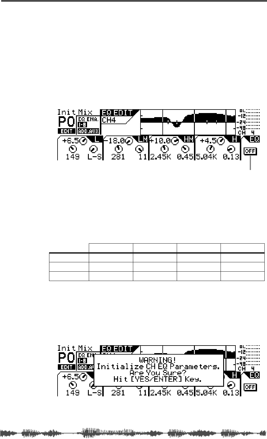
Resetting the EQ
VM200 User’s Guide
81
The EQ On/Off indicator in the lower-right corner of the display
displays “On” to indicate that the EQ is turned on for the specified
channel.
4.
To turn the EQ off for the channel, press the
[EQ ON]
key
again.
The
[EQ ON]
key turns off (goes dark), and the VM200 turns off the
EQ for the selected channel.
The EQ On/Off indicator in the lower-right corner of the display
displays “Off” to indicate that the EQ is turned off for the specified
channel.
Resetting the EQ
To reset all EQ parameters for the selected channel to their initial val-
ues, follow the steps below.
The following table shows initial EQ values.
1.
Press the
[EQ EDIT]
key of the channel whose EQ you wish to
reset to the initial value.
The
[EQ EDIT]
key lights up and the
EQ EDIT
function page appears.
2.
While pressing and holding down the
[ENTER]
key, press the
[EQ EDIT]
key.
The following confirmation dialog appears on the display.
3.
Press the
[ENTER]
key to proceed, or press the
[EXIT]
key to
cancel the reset operation.
Lo Lo-Mid Hi-Mid Hi
Gain (G)
0 dB 0 dB 0 dB 0 dB
Frequency (F)
125 Hz 500Hz 2.00 kHz 8.00 kHz
Q
L-S(Lo-Shelf) 1.0 1.0 H-S(Hi-Shelf)
EQ On/Off indicator. Here, EQ is bypassed.

EQ
82
VM200 User’s Guide
If you have pressed the
[ENTER]
key, all EQ parameters for the
channel will be reset to the initial values.
4.
Press the
[EXIT]
key or the
[CHANNEL/METER]
key to return to
Channel Edit mode.
EQ Library
VM200 User’s Guide
83
EQ Library
You can store EQ settings as programs in the EQ Library.
The EQ Library contains 50 preset programs (Preset Library: 0–49)
and 50 user programs (User Library: 50–99).
For information on recalling EQ programs, see “Recalling EQ Pro-
grams” on page 84.
For information on storing a new or modified EQ program, see “Stor-
ing EQ Programs” on page 86.
EQ Preset Library List
# Name # Name
00 Flat_EQ 25 Real_Pf
01 LightKick 26 E.Pf
02 TightKick 27 Clean_EG
03 Loud_Kick 28 Crunch_EG
04 Ana.Kick 29 OverDrvEG
05 Snappy_SD 30 Dist.EG
06 Power_SD 31 Metal_EG
07 Deep_SD 32 Stroke_AG
08 Talk_Tom 33 StrokeEAG
09 Melo.Tom 34 Arpeg.GG
10 W.GongTom 35 Arpeg.EAG
11 Brill.Cym 36 Arpeg.AG
12 Lo-Fi_Cym 37 Brass_Sec
13 Vivid_HH 38 W.WingSec
14 Sharp_HH 39 Male_Vo1
15 Lo-Fi_HH 40 Male_Vo2
16 Perc. 41 FemaleVo1
17 Tamb. 42 FemaleVo2
18 Fat_Bass 43 Chorus
19 Norm.Bass 44 Speech_1
20 Loud_Bass 45 Speech_2
21 PowerBass 46 Digi.Mix
22 Bright_Pf 47 AnalogMix
23 Loud_Pf 48 Telephone
24 Power_Pf 49 Husky
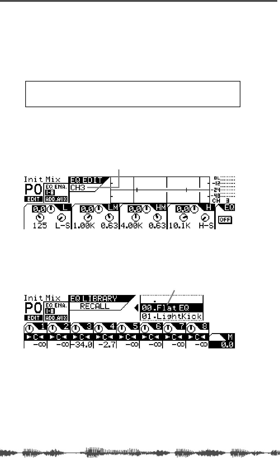
EQ
84
VM200 User’s Guide
Recalling EQ Programs
You can recall EQ programs from the EQ Library, which includes 50
Preset programs and 50 User programs.
1.
Press the
[1–8 ANALOG IN]
or
[9–16 ADAT IN]
Page Select key to
select the desired channel layer.
The selected Page Select key lights up.
2.
Press the
[EQ EDIT]
key for the channel to which you want to
recall an EQ setting.
The selected
[EQ EDIT]
key lights up.
The VM200 displays the
EQ EDIT
function page, which shows the
parameter settings for the selected channel.
3.
Press the Selected EQ
[EQ ON]
key to turn it on.
4.
Press the EQ Library
[RECALL]
key.
The VM200 displays the
EQ LIBRARY RECALL
function page. The
[EQ
EDIT]
key for the selected channel flashes.
5.
Rotate the Data Wheel or use the [</-1] and [+1/>] keys to
select an EQ program.
EQ Program names and numbers (00 to 99) scroll in the
upper-right of the display.
6.
Press the
[ENTER]
key to recall the desired EQ Program.
The VM200 displays the
EQ EDIT
function page, which shows the
new EQ parameter values applied to the current channel.
Note: Make sure you select the “EQ Enabled” channel layer.
For more information, see “EQ Enabling Channels” on
page
75.
indicates EQ parameter settings for Channel 3
scrollable list of EQ programs

Recalling EQ Programs
VM200 User’s Guide
85
7.
To recall an EQ program for another channel, press the
[EQ
EDIT]
key of the destination channel, then repeat Steps 2
through 5.
8.
Press the
[EXIT]
key at any time to exit the EQ Library Recall
page and return to the
CHANNEL EDIT
function page.
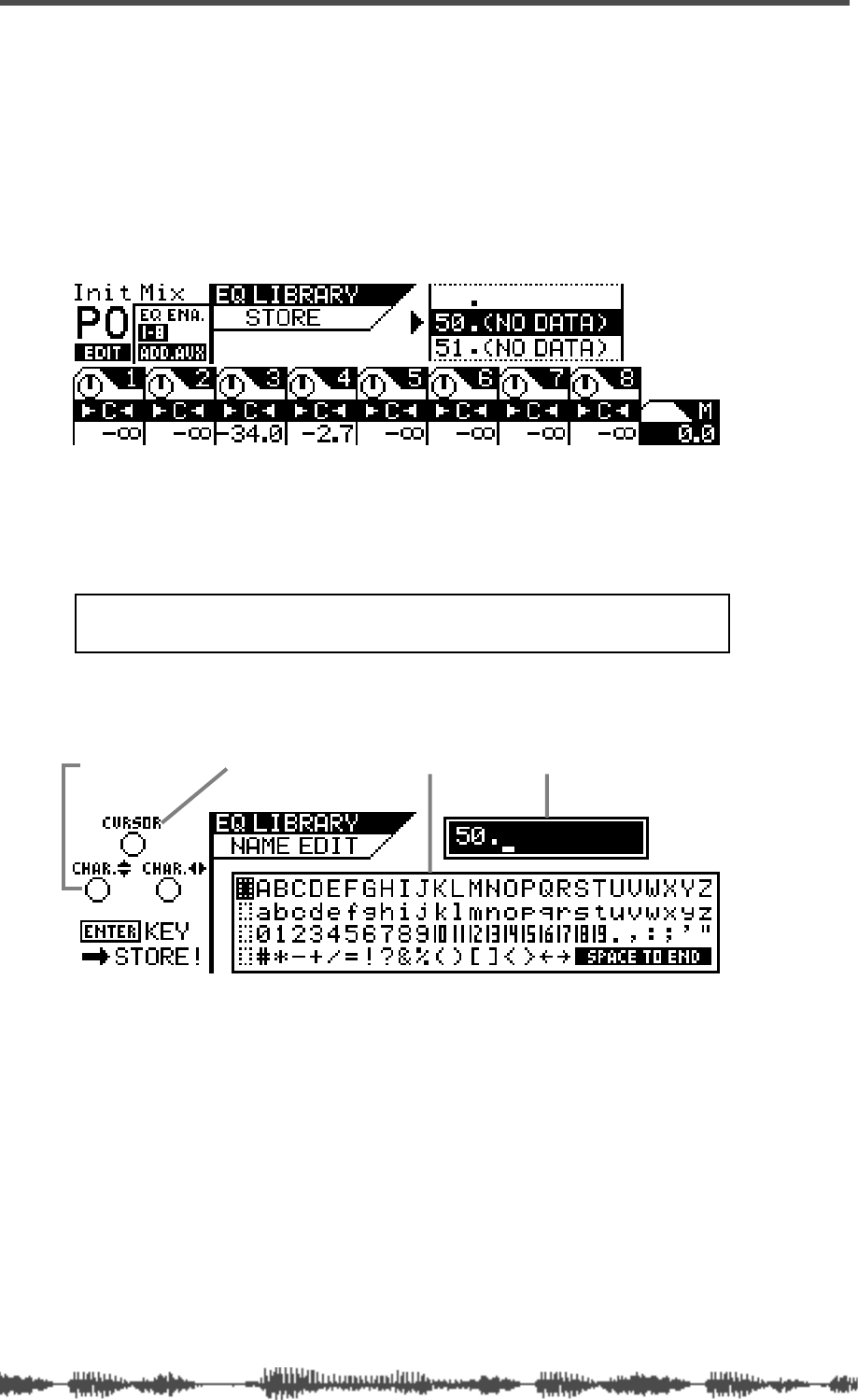
EQ
86
VM200 User’s Guide
Storing EQ Programs
You can store new EQ settings as EQ programs in the EQ Library.
You can store EQ settings as User programs 50 through 99. (Pro-
grams 0 through 49 are read-only Presets.)
1.
Press the EQ Library
[STORE]
key to display the
EQ LIBRARY
STORE
function page.
The
[EQ EDIT]
key of the selected channel flashes.
2.
Rotate the Data Wheel or use the [</-1] and [+1/>] keys to
select an EQ program location (from 50 to 99, inclusive).
EQ Program names and numbers (50 to 99) scroll in the
upper-right of the display.
3.
Press the
[ENTER]
key.
The VM200 displays the
EQ LIBRARY NAME EDIT
function page.
The
EQ LIBRARY NAME EDIT
function page includes a character selec-
tor box that displays all the letters of the alphabet, as well as
numerals and punctuation symbols. You can use these charac-
ters to name or title your EQ program.
You can use any trio of Gain, Freq, and Q rotary controls to select
the characters for the title.
The Gain control moves the cursor left and right in the title box.
The Freq control moves the character-selector up and down the
matrix; the Q control moves the character-selector left and right.
Note: EQ program locations that contain no data are labeled
“(No Data)”.
character-selector title box
character selector boxcursor
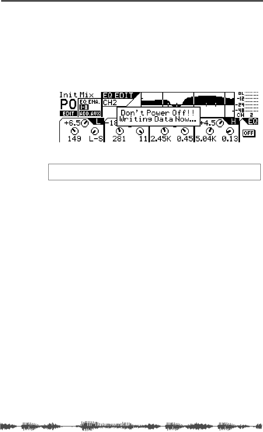
Storing EQ Programs
VM200 User’s Guide
87
4.
Use the Freq and Q controls to select a character, then turn
the Gain control one notch to the right to move the cursor to
the next space in the name, and repeat the process.
The very useful “Space to End” option in the character selector box
will fill-in the remainder of your title with blank spaces.
5.
When you’ve finished naming the program, press the
[ENTER]
key to store the EQ program.
The following warning dialog appears for a brief moment, followed
by the
EQ EDIT
function page.
6.
Press the
[EXIT]
key any time to exit the
EQ LIBRARY STORE
or
EQ
LIBRARY NAME EDIT
function pages.
The VM200 displays the
CHANNEL EDIT
function page.
Warning:
Do not power off the VM200 while it is writing to memory
or you may damage the system.
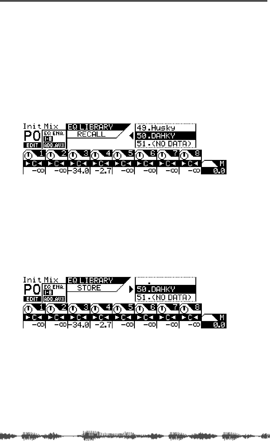
EQ
88
VM200 User’s Guide
Editing EQ Program Titles
You can edit EQ program titles, just in case you want to change its
name for some reason. To do so, you recall the target EQ program to
a channel, then store it again with a different title.
1.
Select a channel to which you wish to recall the EQ program
you are going to rename by pressing the channel
[EQ EDIT]
key.
The VM200 displays the
EQ EDIT
function page.
2.
Press the EQ Library
[RECALL]
key to display the
EQ LIBRARY
RECALL
function page.
The
[EQ EDIT]
key of the selected channel flashes.
3.
Rotate the Data Wheel or use the [</-1] and [+1/>] keys to
select an EQ program you wish to rename.
You cannot change the names of Preset programs 00–49.
4.
Press the
[ENTER]
key to recall the desired EQ Program.
The VM200 displays the
EQ EDIT
function page, which shows the
recalled EQ parameter values applied to the current channel.
5.
Press the EQ Library
[STORE]
key to display the
EQ LIBRARY
STORE
function page.
The VM200 highlights the selected EQ program name and num-
ber.
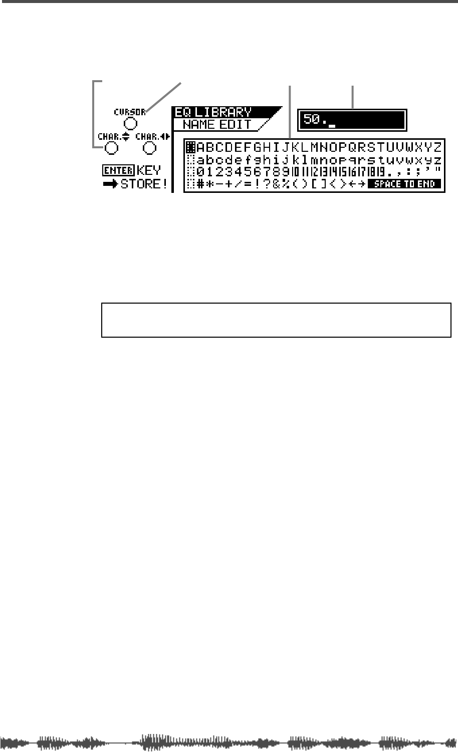
Editing EQ Program Titles
VM200 User’s Guide
89
6.
Press the
[ENTER]
key.
The VM200 displays the
EQ LIBRARY NAME EDIT
function page. The
title box shows the program number, but the name is now blank.
Use any Gain, Freq, and Q rotary controls to re-assign a name to
the EQ program. Refer to “Storing EQ Programs” on page 86 for
more information on controlling the cursor and character selector.
7.
When you’ve finished re-naming the program, press the
[ENTER]
key to store the new EQ program title.
The VM200 displays the
EQ EDIT
function page.
8.
Press the
[EXIT]
key at any time to exit the
EQ LIBRARY STORE
or
EQ LIBRARY NAME EDIT
function pages.
The VM200 displays the
CHANNEL EDIT
function page.
character-selector title box
character selector boxcursor
WARNING: Do not power off the VM200 while it is writing to
memory or you may damage the system.
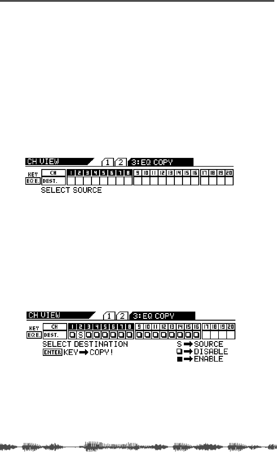
EQ
90
VM200 User’s Guide
Copying EQ Settings
You can use the EQ Copy function to copy EQ settings from one
channel to another.
The
EQ COPY
function page features a 1-by-20 matrix that enables you
to select one source channel EQ, and enable or disable the other
channels as copy destinations.
The selected source channel EQ is marked by an “S.” A highlighted
indicator marks the channels targeted as copy destinations. A dark
indicator means the channel is not selected (disabled) as a copy des-
tination.
1.
Press the
[CH VIEW]
key twice (from start of cycle).
The VM200 displays the
3:EQ COPY
function page.
The
[CH VIEW]
key and the
[EQ EDIT]
keys for all channels flash. The
selected Page Select key lights up; unselected Page Select keys flash.
2.
Press the appropriate Page Select key to select the desired
channel layer.
The selected Page Select key lights up; unselected Page Select keys
continue to flash.
3.
Press the
[EQ EDIT]
key for the EQ copy source channel.
You can select only one source channel EQ to copy at a time.
The selected
[EQ EDIT]
key lights up. The
EQ COPY
function page
marks the source channel with an “S” and prompts you to select a
destination channel.
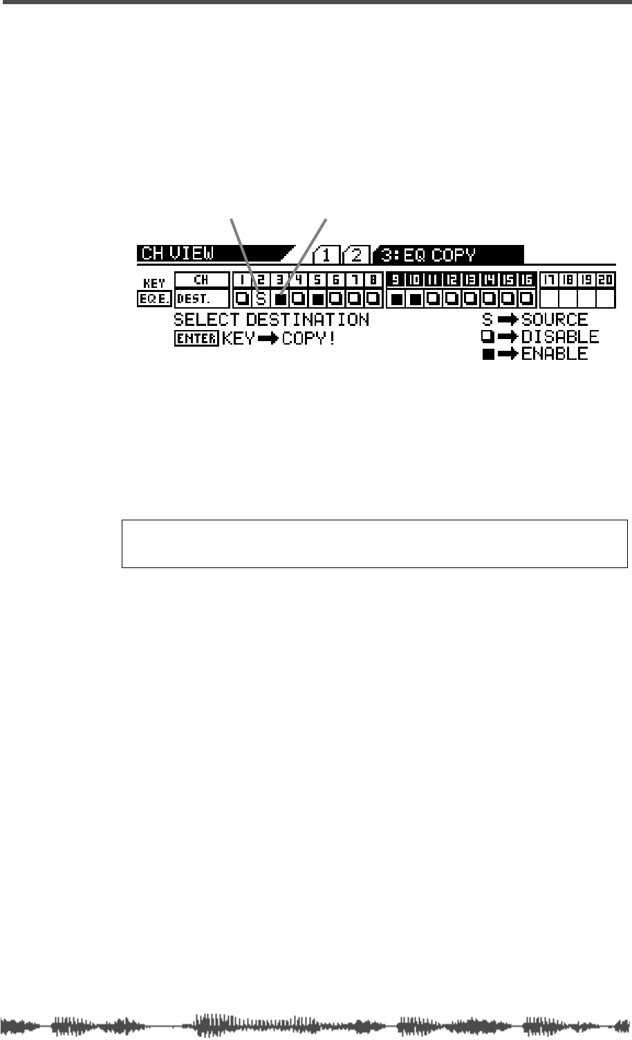
Copying EQ Settings
VM200 User’s Guide
91
4.
Press the appropriate Page Select key to specify the channel
layer, then press the
[EQ EDIT]
key of the copy destination
channel(s).
You can select multiple channels as EQ copy destinations.
The selected
[EQ EDIT] key(s) light up. The EQ COPY function page
highlights (enables) the selected destination channel(s) as follows.
5. Press the [ENTER] key to execute the copy operation.
The EQ COPY function page flashes the word “COMPLETE!” on the
display for a few seconds, and the VM200 displays the first CH COPY
function page.
6. Press the [EXIT] key or the [CHANNEL/METER] key to return to
Channel Edit mode.
source channel oneof four destination channels
Note: Even if channels are paired, you can copy to and from each
of the paired channels independently.
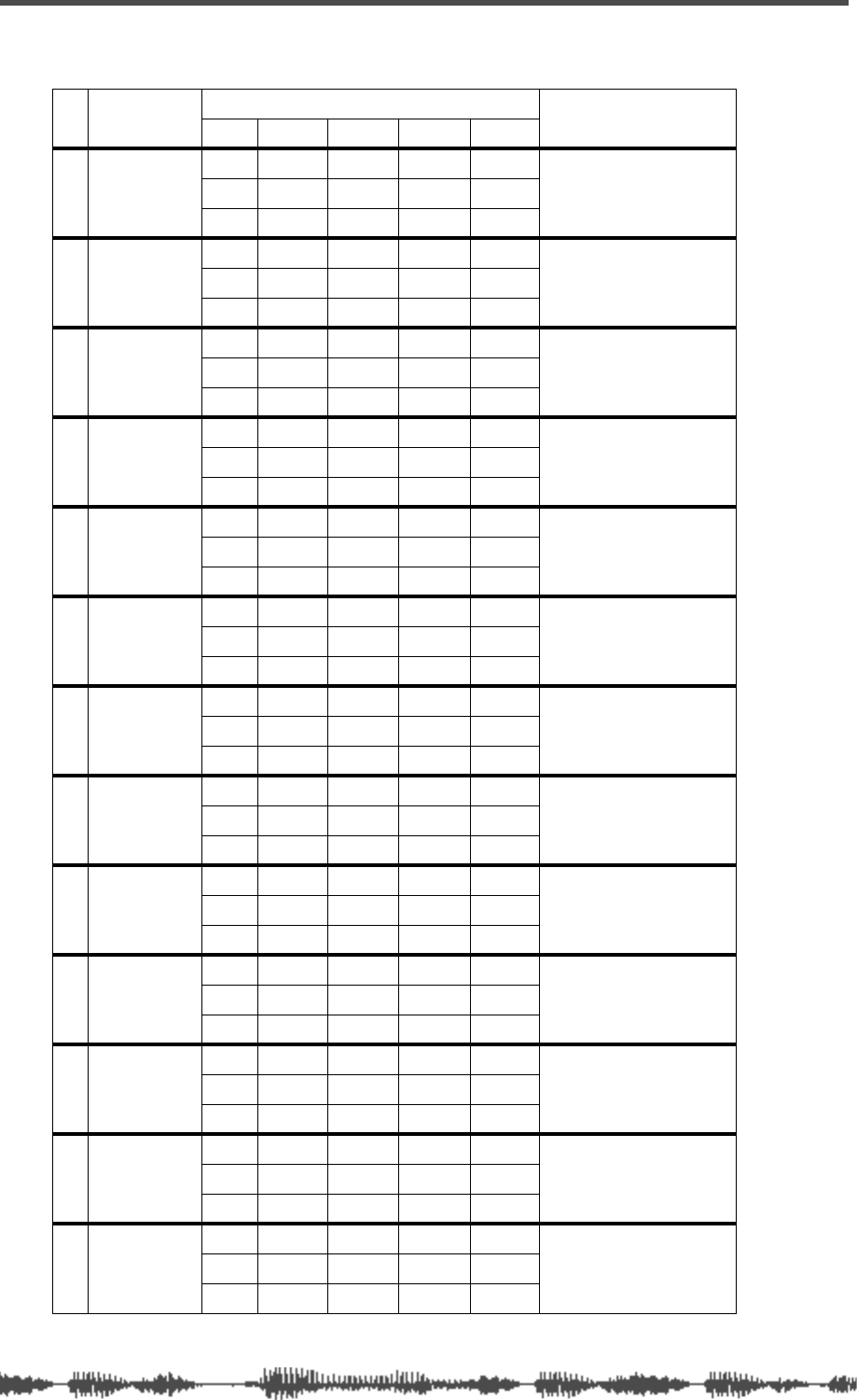
EQ
92 VM200 User’s Guide
EQ Preset Library Parameters
# Name Parameter Description
Lo Lo-Mid Hi-Mid Hi
00 Flat_EQ
Gain 0.0dB 0.0dB 0.0dB 0.0dB A flat equalizing pattern
used for initialized EQ.
Freq. .125 500 2.00K 8.00K
QL-S 1.0 1.0 H-S
01 LightKick
Gain +4.0 -12.0 +4.0 0.0 Relatively light and nim-
ble kick sound.
Freq. 105 324 4.12K 8.00K
Q1.6 11 0.40 HS
02 TightKick
Gain +8.0 -7.5 +6.5 ON Creates a peak around
70Hz, producing a tight,
stiff sound.
Freq. 70.2 364 2.83K 13.5K
Q1.1 5.0 2.8 LPF
03 Loud_Kick
Gain +4.5 -6.5 +5.0 +4.0 Emphasizes the attack
of the beat, increasing
the mass of the entire
kick.
Freq. 102 306 1.46K 6.35K
Q1.0 3.2 4.5 H-S
04 Ana.Kick
Gain +5.5 +1.0 -6.0 -1.5 Makes an analog kick
sound more boomy.
Freq. 102 91.0 2.12K 12.7K
QL-S 5.0 7.9 H-S
05 Snappy_SD
Gain -4.5 0.0 _3.5 +4.0 Emphasizes snare
sounds.
Freq. 111 841 3.89K 8.23K
QL-S 3.5 0.16 H-S
06 Power_SD
Gain +2.0 -9.5 +3.5 +4.5 Adds powerful thrust
and clarifies snare
sound.
Freq. 149 281 2.45K 5.04K
QL-S 11 0.45 0.13
07 Deep_SD
Gain 0.0 +3.0 +4.0 0.0 Creates a heavy-weight
snare sound with great
depth.
Freq. 125 545 4.24K 8.00K
QL-S 4.5 2.2 H-S
08 Talk_Tom
Gain +9.5 -10.0 +9.0 +2.0 Creates the “leathery”
decay of a tom.
Freq. 102 687 4.36K 10.7K
Q2.0 6.3 1.4 H-S
09 Melo.Tom
Gain -10.0 +2.0 +2.5 0.0 Creates a melodious
atmosphere by limiting
the body resonance of a
tom.
Freq. 83.4 216 5.50K 8.00K
QL-S 4.5 1.1 H-S
10 W.GongTom
Gain -12.00 +10.00 -8.0 -12.0 Creates a wooden tom
sound.
Freq. .125 500 3.78K 8.00K
QL-S 5.0 11 H-S
11 Brill.Cym
Gain -6.0 -1.0 0.0 +7.0 Creates a “sparkling”
and brilliant cymbal
sound.
Freq. 55.7 397 1.94K 5.66K
QL-S 8.9 1.0 H-S
12 Lo-Fi_Cym
Gain 0.0 +2.5 -4.0 -&.0 Emphasizes the mid to
low range to muffle
“sparkling” part of cym-
bals.
Freq. 40.5 172 3.27K 4.00K
QL-S 3.2 11 H-S
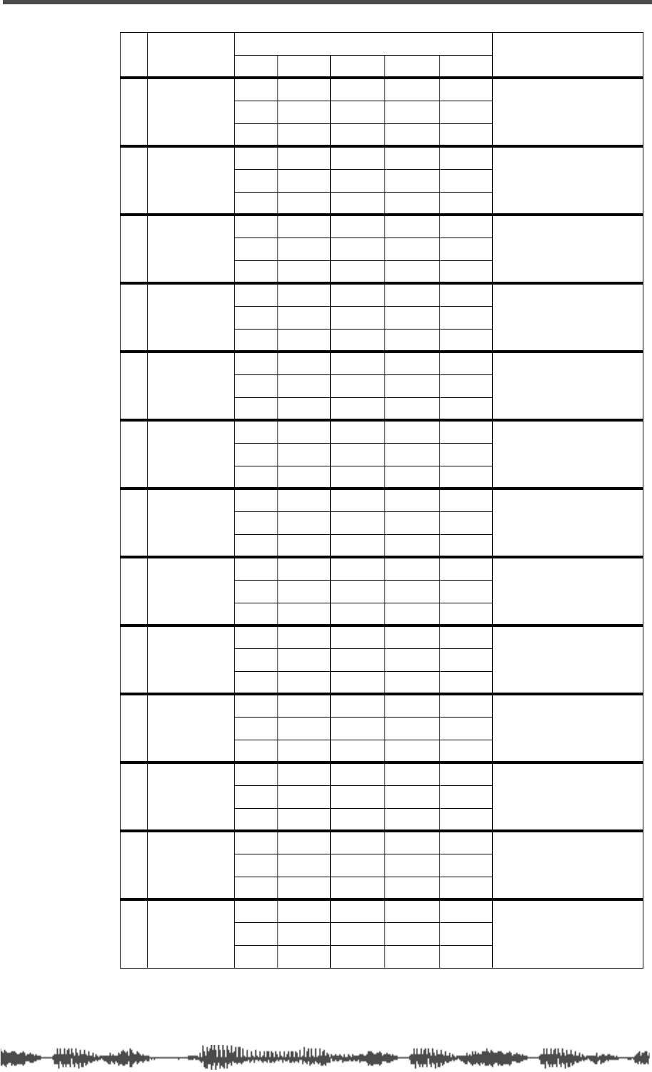
EQ Preset Library Parameters
VM200 User’s Guide 93
13 Vivid_HH
Gain -7.5 -2.5 +4.0 +4.0 Emphasizes the pres-
ence of a high-hat in the
ensemble.
Freq. 93.6 472 2.31K 8.00K
QL-S 0.79 1.0 H-S
14 Sharp_HH
Gain -9.0 -6.5 +4.5 +3.5 Creates a tight high-hat
with stiff and powerful
characteristics.
Freq. 68.2 771 7.13K 16.0K
QL-S 5.6 10 0.10
15 Lo-Fi_HH
Gain -2.5 0.0 +4.5 -18.0 Eliminates metallic ele-
ments and emphasizes
lo-fi high-hat sound.
Freq. 93.6 472 2.31K 8.00K
QL-S 0.79 0.71 H-S
16 Perc.
Gain -4.0 0.0 +1.0 +7.0 Emphasizes the attack and
clarifies the high-range of
instruments, such as con-
gas, and bongos.
Freq. 102 397 1.94K 5.82K
QL-S 4.5 0.35 H-S
17 Tamb.
Gain -5.0 -0.5 +1.0 +2.5 Creates a subtle
essence by emphasiz-
ing the presence of a
tambourine.
Freq. 125 375 3.17K 8.00K
QL-S 2.5 10 H-S
18 Fat_Bass
Gain 0.0 +4.5 +2.5 +0.5 Makes an electric bass
sound fatter by empha-
sizing the low range.
Freq. 99.2 105 2.38K 4.24K
QL-S 0.10 6.3 H-S
19 Norm.Bass
Gain -9.0 +4.5 +3.5 0.0 Makes an all-round elec-
tric bass sound by cut-
ting very low
frequencies.
Freq. 31.3 105 2.12K 4.24K
QL-S 5.0 0.40 H-S
20 Loud_Bass
Gain +3.5 0.0 +2.5 0.0 Use for analog bass with
boosted low limit and
attack ranges.
Freq. 121 182 1.26K 12.0K
Q2.0 7.9 2.2 H-S
21 PowerBass
Gain +6.0 +3.0 0.0 0.0 Use on a PCM bass with
boosted low range.
Freq. 83.4 917 4.00K 8.00K
QL-S 7.9 3.2 H-S
22 Bright_Pf
Gain -4.0 0.0 +2.5 +5.0 Use to make a piano
sound brighter.
Freq. 81.8 375 2.45K 8.98K
QL-S 3.2 1.6 H-S
23 Loud_Pf
Gain +5.5 -9.0 +2.5 +4.5 Adds “weight” to the low
range of a piano sound
with lots of harmonics.
Freq. 187 578 3.27K 5.34K
Q3.5 10 3.2 H-S
24 Power_Pf
Gain -8.5 -5.5 +4.5 +9.0 Use on a piano solo to
add tightness and
spread.
Freq. 28.7 273 3.17K 8.23K
QL-S 1.0 6.3 3.5
25 Real_Pf
Gain -4.5 +8.0 +1.0 -10.0 Simulates a real
mid-range piano sound,
including the hammer
action during key strokes.
Freq. 51.1 397 1.54K 8.00K
QL-S 4.5 5.6 H-S
# Name Parameter Description
Lo Lo-Mid Hi-Mid Hi
EQ
94 VM200 User’s Guide
26 E.Pf
Gain -6.5 +5.5 +3.5 +10.5 Emphasizes the attack
and distortion of popular
electric piano’s key
strokes.
Freq. 22.1 243 3.56K 20.2K
QL-S 5.0 16 H-S
27 Clean_EG
Gain +3.0 -6.5 +1.0 +3.5 Use for a clean electric
guitar to get a brighter
sound.
Freq. 216 386 1.46K 5.34K
Q0.22 10 6.3 H-S
28 Crunch_EG
Gain +3.0 0.0 +3.5 +3.0 Emphasizes the pres-
ence and adjusts the
tonal quality of a slightly
distorted guitar sound.
Freq. 140 500 2.00K 5.19K
Q7.9 1.0 0.89 7.1
29 OverDrvEG
Gain +3.5 +2.0 +3.0 0.0 Emphasizes the mid
range of mellow over-
drive electric guitar to
add fatness and rich-
ness.
Freq. 108 375 2.59K 8.00K
Q7.9 0.50 0.20 H-S
30 Dist.EG
Gain +5.5 0.0 +4.0 0.0 Makes a heavily dis-
torted guitar sound
clearer.
Freq. 364 917 3.56K 8.00K
QL-S 7.9 10 H-S
31 Metal_EG
Gain +6.5 -9.5 +5.0 +4.0 Emphasizes the edge of
high-gain metal sound.
Freq. 250 1.12K 4.49K 12.0K
QL-S 10 4.0 H-S
32 Stroke_AG
Gain -3.0 0.0 +1.5 +5.5 Emphasizes the bright
chordal strokes of an
acoustic guitar, reduc-
ing the body resonance.
Freq. 125 794 1.94K 7.13K
Q1.0 3.2 2.8 H-S
33 StrokeEAG
Gain -4.0 -3.0 0.0 +2.5 Use on a tight elec-
tric-acoustic guitar in a
band context.
Freq. 250 687 2.00K 4.49K
QL-S 8.9 1.0 H-S
34 Arpeg.GG
Gain -3.0 -3.0 +4.0 +2.5 Corrects and clarifies
the arpeggio technique
of a gutsy guitar sound.
Freq. 149 223 3.08K 8.00K
QL-S 4.0 5.6 H-S
35 Arpeg.EAG
Gain -1.5 0.0 0.0 +3.0 Adjusts the balance of
chords & arpeggios of
an electric acoustic gui-
tar sound.
Freq. 210 1.00K 3.78K 9.42K
QL-S 4.0 4.0 0.10
36 Arpeg.AG
Gain 0.0 -6.5 0.0 +5.0 Cuts the body resonance
of an acoustic guitar
sound and clarifies an
arpeggio guitar sound.
Freq. 149 530 2.52K 4.24K
QL-S 7.1 4.5 H-S
37 Brass_Sec
Gain -2.5 0.0 +2.0 +4.0 Adjusts the balance of
brass section sound
(such as trumpets and
trombones).
Freq. 96.4 917 2.52K 5.66K
Q2.5 1.6 0.79 5.0
38 W.WingSec
Gain +3.0 +4.0 0.0 0.0 Emphasizes the rich
mid-range of wind
instruments, such as
clarinets and oboes.
Freq. 125 257 3.38K 8.00K
QL-S 2.2 2.5 H-S
# Name Parameter Description
Lo Lo-Mid Hi-Mid Hi
EQ Preset Library Parameters
VM200 User’s Guide 95
39 Male_Vo1
Gain -1.0 0.0 +2.0 +3.0 Adds changes to
expression male of tenor
vocals.
Freq. 157 1.00K 2.00K 6.17K
QL-S 4.5 0.56 H-S
40 Male_Vo2
Gain +2.5 -4.0 -2.0 +4.5 Adds changes to
expression of bass and
baritone male vocal
sound
Freq. 140 243 2.59 6.73K
QL-S 7.9 3.2 H-S
41 FemaleVo1
Gain -2.0 +1.5 +2.0 +3.0 Adds changes to
expression of soprano
female vocal sound.
Freq. 121 408 2.59K 8.72K
QL-S 0.45 0.63 H-S
42 FemaleVo2
Gain -7.0 +2.0 +2.5 +3.5 Adds changes to
expression of alto
female vocal sound.
Freq. 118 324 2.06K 6.73K
QL-S 0.20 0.22 H-S
43 Chorus
Gain -3.0 -0.5 +1.0 +3.5 Adds changes to
expression of the entire
high-tone chorus part.
Freq. 99.2 817 2.12K 5.34K
Q3.2 2.2 0.71 7.9
44 Speech_1
Gain -4.5 -1.5 +1.5 0.0 Use to record clear male
narration.
Freq. 99.2 687 2.59K 8.00K
Q4.5 7.1 0.71 H-S
45 Speech_2
Gain -5.0 -2.0 +3.5 0.0 Use to record clear
female narration.
Freq. 55.7 229 2.67K 8.00K
QL-S 3.5 1.0 H-S
46 Digi.Mix
Gain +6.0 0.0 0.0 +6.0 Use to record from classic
analog 6mm or cassette
tape to make the sound
clearer, like digital audio.
Freq. 51.1 420 4.00K 12.0K
QL-S 1.0 1.0 H-S
47 AnalogMix
Gain ON -7.0 -7.0 ON Cuts the high range to
obtain the reverse
effects of program 45.
Freq. 33.1 57.3 6.54K 10.7K
QHPF 3.5 1.4 LPF
48 Telephone
Gain ON 0.0 +12.0 ON Emphasizes only the
mid range to simulate a
telephone sound.
Freq. 420 500 1.00K 2.52K
QHPF 1.0 5.0 LPF
49 Husky
Gain ON -5.5 +2.0 +8.0 Emphasizes only the
high range to creates a
husky voice.
Freq. 102 172 4.62K 8.00K
QHPF 1.0 0.32 H-S
# Name Parameter Description
Lo Lo-Mid Hi-Mid Hi

EQ
96 VM200 User’s Guide

DIGITAL RECORDING MIXER
RECORDING MIXER
VM200
REC BUSS
REC BUSS
EFF EDIT
EFF EDIT
SELECTED EQ
SELECTED EQ
EQ/HI
EQ/HI
EQ/HI-MID
EQ/HI-MID
EQ/LO-MID
EQ/LO-MID
EQ/LO
KEY MODE
+10
0
-10
-20
-30
-40
-
+10
0
-10
-20
-30
-30
-40
-40
-
+10
0
-10
-20
-30
-40
-
+10
0
-10
-20
-30
-40
-
+10
+10
0
-10
-20
-30
-40
-40
-
+10
0
-10
-20
-30
-40
-
+10
0
-10
-20
-30
-40
-
16
8
GAIN
GAIN
FREQ
FREQ
PAN
AN
Q
PAN
AN
ON
ON
ON
ON
ON
ON
ON
ON
ON
ON
ON
ON
ON
ON
SOLO
SOLO
SOLO
SOLO
SOLO
SOLO
SOLO
SOLO
SOLO
SOLO
SOLO
SOLO
SOLO
SOLO
EQ EDIT
EQ EDIT
EQ EDIT
EQ EDIT
EQ EDIT
EQ EDIT
EQ EDIT
EQ EDIT
EQ EDIT
EQ EDIT
EQ EDIT
EQ EDIT
EQ EDIT
EQ EDIT
EQ EDIT
EQ EDIT
SOLO
SOLO
ON
ON
ON
ON
SOLO
SOLO
EQ LIBRAR
EQ LIBRAR
Y
ST
ST
ORE
ORE
RECALL
RECALL
EQ ON
EQ ON
EFF LIBRAR
EFF LIBRAR
Y
ST
ST
ORE
ORE
RECALL
RECALL
EFF2
EFF2
EFF1
EFF1
RECALL
RECALL
SOLO
SOLO
EXIT
EXIT
15
7
14
6
13
5
12
4
11
3
10
2
9
1
20
19
18
FREQ
FREQ
Q
FREQ
FREQ
Q
FREQ
Q
GAIN
GAIN
GAIN
GAIN
GAIN
1-8 ANALOG IN
9-16 ADA
ADA
T IN 17-20 EFF RTN
17-20 EFF RTN
P
AGE SELECT
AGE SELECT
GROUP
GROUP
PAIR/
AIR/
CH VIEW
METER
METER
CHANNEL/
CHANNEL/
AUX1
FADER MODE
AUX2
AUX3 AUX4
EFF1 EFF2
CHANNEL
ADD.AUX
TRIM
-10 -50
TRIM TRIM TRIM
-10 -50 -10 -50 -10 -50
INPUT 6 INPUT 7 INPUT 8
MIN
MIN
MAX
MAX MIN
+10
0
1
0
-10
-20
-30
-40
-
0
-10
-20
-30
-60
-
-40
MMC SEND
MMC SEND
PAN
AN
PAN
AN
PAN
AN
PAN
AN
PAN
AN
PAN
AN
-40
-36
-24
-18
12-12
-9
-6
-3
OL
ST BUSS/SOLO
ST BUSS/SOLO
L R
METER
VM200 User’s Guide
97
CHAPTER 6
Monitoring Signals
About This Chapter
This chapter explains how to monitor signals on the VM200, includ-
ing selecting a monitor output, soloing, using the two-track input,
as well as viewing meters and send levels.
Chapter Contents
Monitoring and Soloing . . . . . . . . . . . . . . . . . . . . . . . . . . . 98
MON SEL Parameter. . . . . . . . . . . . . . . . . . . . . . . . . . . . 98
SOLO MODE Parameter . . . . . . . . . . . . . . . . . . . . . . . . . 98
Two Track Input (2TRK IN) . . . . . . . . . . . . . . . . . . . . . . . 99
Monitoring . . . . . . . . . . . . . . . . . . . . . . . . . . . . . . . . . . . . 100
Soloing . . . . . . . . . . . . . . . . . . . . . . . . . . . . . . . . . . . . . . . 101
Metering Signal Levels . . . . . . . . . . . . . . . . . . . . . . . . . . . 105
Viewing Input/Output Level Meters . . . . . . . . . . . . . . . 105
LED Display Meter (L/R or ST BUSS/SOLO). . . . . . . . . 106
Viewing Individual Channel, Aux Send, and Effect Send Meters106
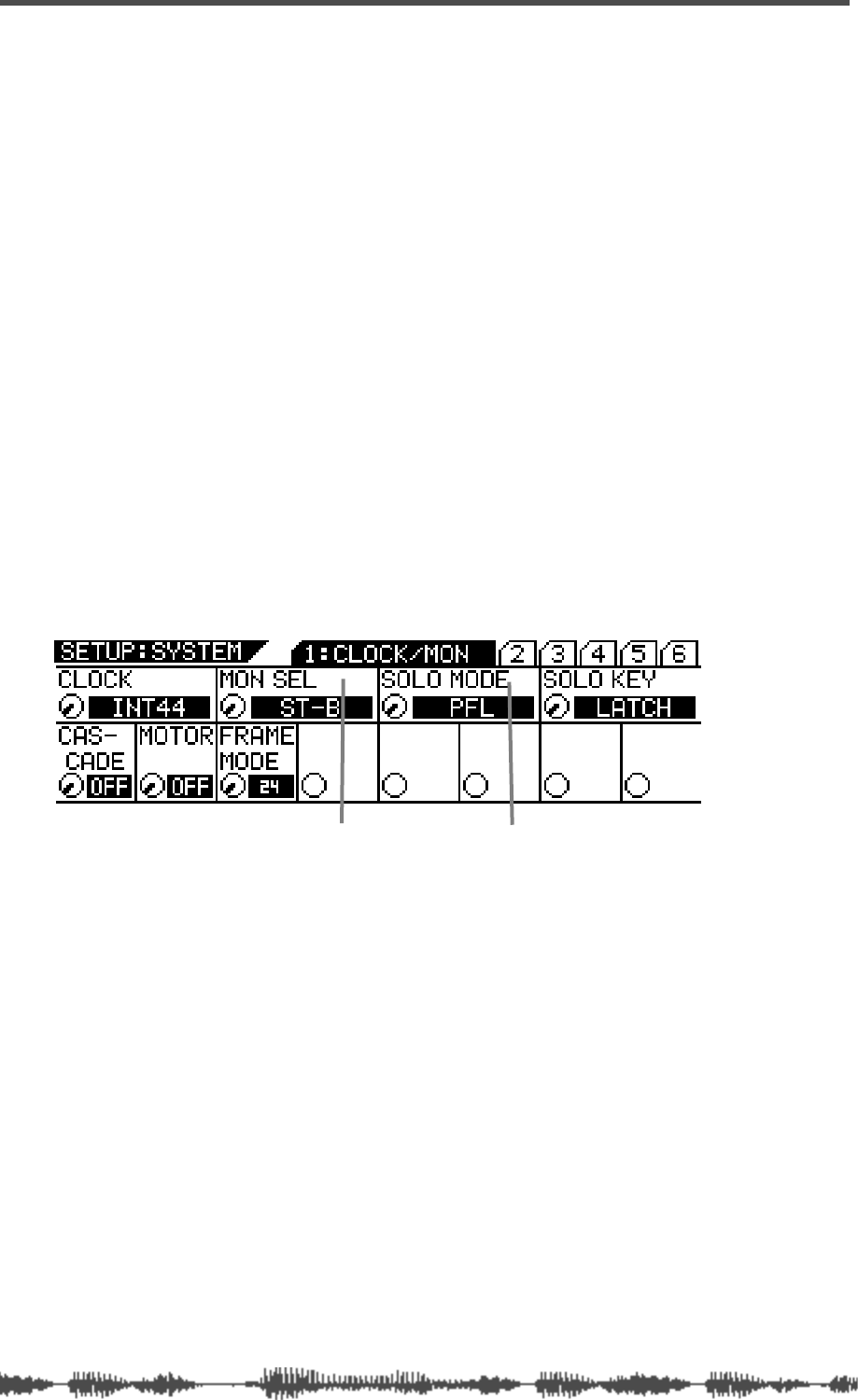
Monitoring Signals
98
VM200 User’s Guide
Monitoring and Soloing
The flexible monitoring and soloing capabilities of the VM200 enable
you to use the mixer in a wide range of applications.
The monitoring functions enable you to listen to input channel sig-
nals or buss signals through connected monitor speakers or head-
phones.
The soloing function enables you to select the channels you want to
hear while excluding all other channels. This lets you focus your
attention on certain tracks in the mix.
For example, say you want to listen closely to the way the rhythm sec-
tion is working in a mix. The solo function lets you “solo” the chan-
nels that carry the bass and drums, while excluding the channels
dedicated to the other instruments.
You specify the channels you want to hear by pressing the corre-
sponding channel
[SOLO]
keys on the top panel.
The Setup:System
1:CLOCK/MON
function page features two parameters
that control the monitoring and soloing functions of the VM200: the
MON SEL (monitor select) and SOLO MODE parameters.
You can display the
1:CLOCK/MON
function page by pressing the
[SYS-
TEM]
key.
MON SEL Parameter
The Mon Sel (Monitor Select) parameter enables you to select the
source for the MONITOR OUT and PHONES jack.
(However, if a channel is “soloed,” it will override the selection of the
Mon Sel parameter.)
You can select one of the following sources: ST-B (stereo buss),
REC-B (record buss), AUX1, AUX2, AUX3, AUX4, EFF1, EFF2,
AUX1&2, or AUX3&4. For more information on these options, see
“Monitoring” on page 100.
SOLO MODE Parameter
The Solo Mode parameter enables you to configure the solo function
of the VM200.
You can solo input channels 1 through 20 and the buss outs by
MON SEL parameter SOLO MODE parameter
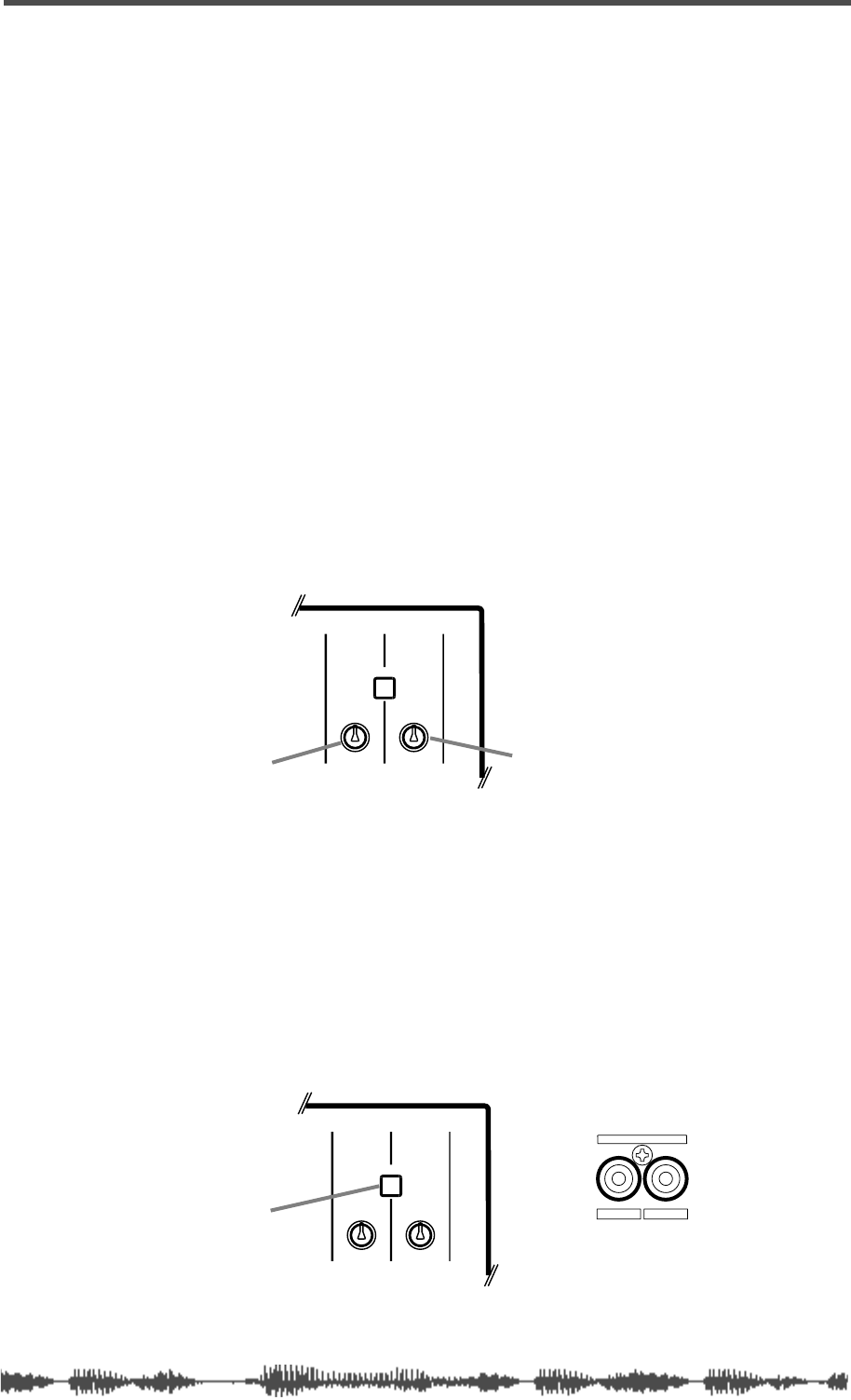
Monitor Outs and Phones
VM200 User’s Guide
99
pressing the
[SOLO]
key for the desired channel.
Two Solo modes are available: PFL (Pre-Fader Listen) and M–SOLO
(Mix Solo).
See “Soloing” on page 101 for more information.
Monitor Outs and Phones
You can output Monitor and Solo signals via the MONITOR OUT and
PHONES jacks.
Make sure the 2TRK IN switch is not pressed in for monitoring (unless
you want to confidence monitor), or you will not hear a signal. (See
2TRK IN, below, for more information.)
You can connect a monitor system (amplifier and speakers) to the
MONITOR OUT phono jacks on the rear panel. You can use the Mon-
itor Gain control, located at the top right of the control surface, to
adjust the level of the monitor out signal.
You can connect a pair of stereo headphones to the PHONES stereo
(TRS) phone jack. The PHONES signal is the same as the MONITOR
OUT signal. You can adjust the level of the phones signal using the
Phones Gain control.
Two Track Input (2TRK IN)
If you press the 2TRK IN switch on the top panel, you can monitor
signals that are connected to the 2TRK IN jacks on the rear panel.
The signal is sent to the MONITOR OUT and PHONES jacks.
You can connect the stereo outputs of a master recorder, for exam-
ple, to the 2TRK IN jacks for confidence monitoring or master play-
back.
The 2TRK IN accepts phono jacks with a –10 dBV nominal input level.
MONITOR Gain PHONES Gain
(top panel}
MIN MAX
GAIN
MAXMIN
GAIN
2TRK IN
PHONESMONITOR
2TRK IN jacks (rear panel)
2TRK IN switch
MIN MAX
GAIN
MAXMIN
GAIN
2TRK IN
PHONESMONITOR
RL
2TRK IN
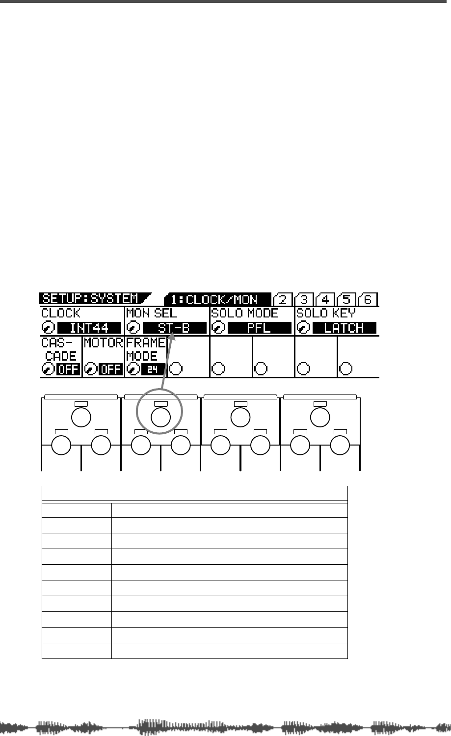
Monitoring Signals
100
VM200 User’s Guide
Monitoring
You can monitor the following sources: Stereo Buss, Rec Buss,
Aux1, Aux2, Aux3, Aux4, Eff1, Eff2, Aux 1&2, or Aux 3&4. (AUX 3
and 4 are available only when the ADD. AUX parameter is turned
on. For more information, see page 115.)
You can select a monitor source using the monitor select (Mon Sel)
parameter on the first
SYSTEM
function page. Follow these steps:
1.
Make sure a monitoring system (amp and speakers) is con-
nected to the MONITOR OUT jacks, or that stereo headphones
are connected to the PHONES jack. Also, make sure the 2TRK
IN switch is
not
pressed in.
2.
Set the Monitor Gain control to about halfway.
(For headphones, set the Phones Gain control to about halfway.)
3.
Press the Setup
[SYSTEM]
key.
The VM200 displays the
1:CLOCK/MON
function page.
4.
Rotate the channel 3/4 (EQ/LO-MID) Gain rotary control to
select the desired source for the Mon Sel parameter.
5.
Press the
[CHANNEL/METER]
or
[EXIT]
key.
The VM200 exits Setup mode and displays the
CHANNEL EDIT
func-
tion page.
MONITOR SELECT (MON. SEL.) PARAMETER OPTIONS
ST-B
Stereo Buss (default setting)
REC-B
Record Buss
AUX1
Auxiliary 1
AUX2
Auxiliary 2
AUX3
Auxiliary 3
AUX4
Auxiliary 4
EFF1
Effect processor EFF1
EFF2
Effect processor EFF2
AUX1&2
Auxiliary 1 and Auxiliary 2 mixed
AUX3&4
Auxiliary 3 and Auxiliary 4 mixed
EQ/HI
EQ/HI-MIDEQ/LO-MIDEQ/LO
GAIN
FREQ
PAN
Q
PAN
FREQ QFREQ Q
FREQ Q
GAINGAINGAIN
PANPANPANPANPANPAN
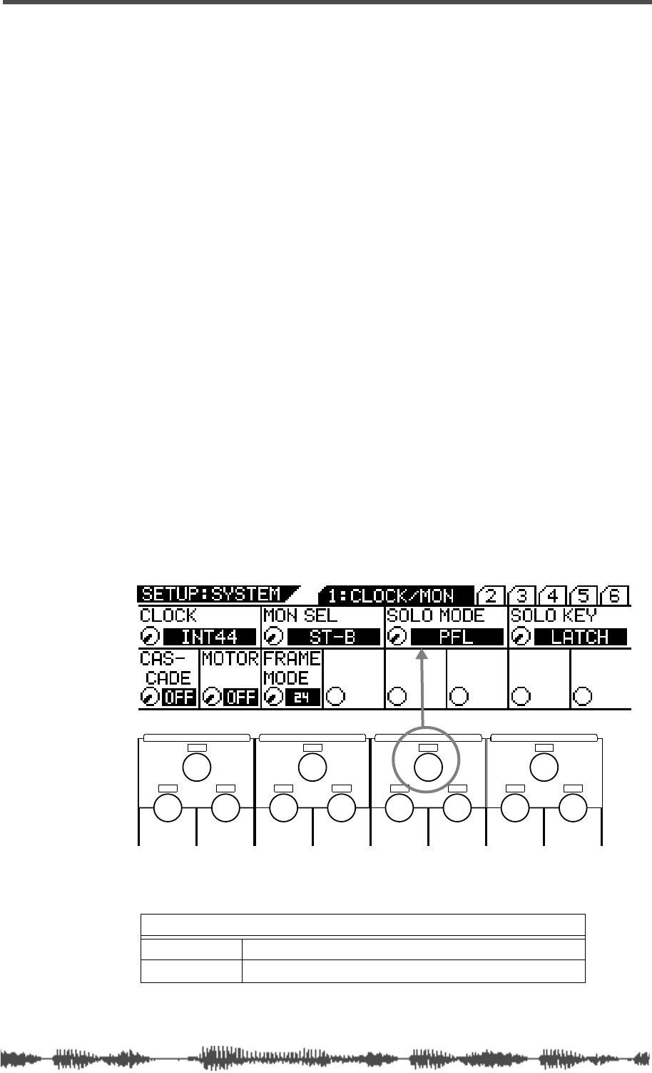
Soloing
VM200 User’s Guide
101
Soloing
A Solo function is available for input channels 1 through 20 that
enables you to monitor specific channels.
Two solo modes are available: PFL and M-Solo.
PFL is an abbreviation for Pre-Fader Listen, in which you can monitor
a signal that appears before it is adjusted by the fader.
M-Solo means “mix solo,” which enables you to momentarily monitor
the stereo buss signal (i.e., the mix).
You can select a solo mode by using the Solo Mode parameter on the
first
SETUP:SYSTEM
function page.
You can also control how
[SOLO]
keys are turned on and off.
To use the Solo function, follow the steps below:
1.
Make sure a monitoring system (amp and speakers) is con-
nected to the MONITOR OUT jacks, or that stereo headphones
are connected to the PHONES jack. Also, make sure the 2TRK
IN switch is
not
pressed in.
2.
Set the Monitor Gain control to about halfway.
(If you are using headphones, set the Phones Gain control to
about halfway.)
3.
Press the Setup
[SYSTEM]
key.
The VM200 displays the
1:CLOCK/MON
function page.
4.
Rotate the channel 5/6 (EQ/HI-MID) Gain rotary control to
select the desired Solo Mode.
SOLO MODE PARAMETER OPTIONS
PFL
Pre-Fader Listen mode (default setting)
M-SOLO
Mix-solo mode
EQ/HI
EQ/HI-MIDEQ/LO-MIDEQ/LO
GAIN
FREQ
PAN
Q
PAN
FREQ QFREQ Q
FREQ Q
GAINGAINGAIN
PANPANPANPANPANPAN
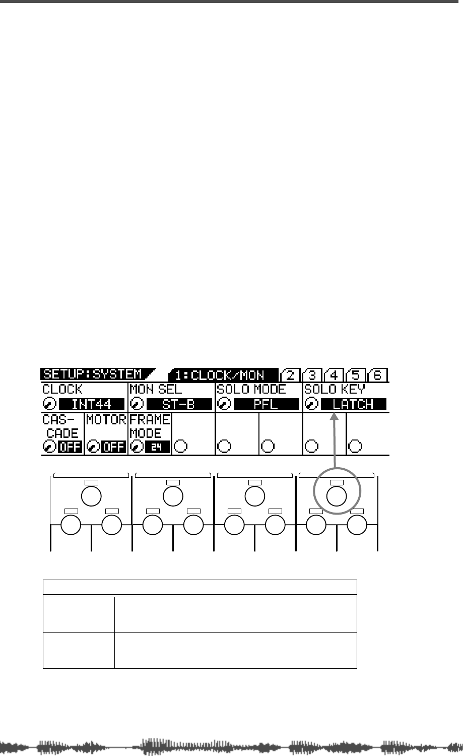
Monitoring Signals
102
VM200 User’s Guide
PFL:
In PFL (Pre-Fader Listen) mode, the VM200 feeds a soloed
channel’s pre-fader signal to the Solo buss and then outputs it
only to the MONITOR OUT and PHONES.
Pressing the appropriate
[SOLO]
key enables you to solo the stereo
master or Rec Buss signal before it is adjusted by the Master
Fader or Rec Buss Gain parameter.
You can use this mode to monitor individual input signals during
a recording session to make isolated EQ adjustments or to ensure
that the signals are not clipping.
You can solo input channels that are turned off (i.e., that have
their
[ON]
keys turned off).
M-Solo:
In Mix-Solo mode, the VM200 feeds a soloed channel to
the stereo buss, and then outputs it to the ST BUSS OUT, MONI-
TOR OUT, and PHONES. You can solo only channels that are
routed to the Stereo Buss.
The VM200 mutes all channels except the channel you select to
solo. (However, you can use a Solo Safe function in this mode. For
more information, see “Solo Safe Function” on page 104.)
In this mode, Master and Rec Buss
[SOLO]
keys are disabled.
You can use this mode to adjust individual channels during mix-
down.
5.
Rotate the channel 7/8 (EQ/HI) Gain rotary control to select
a Solo Key mode.
6.
Press the
[CHANNEL/METER]
or
[EXIT]
key.
The VM200 exits Setup mode and displays the
CHANNEL EDIT
func-
tion page.
SOLO KEY PARAMETER OPTIONS
LATCH
In Latch mode, when you press a [SOLO] key, it remains
depressed, and the channel continues to solo
until you
press the key again
. This is the default setting.
UNLATCH
In Unlatch mode, when you press and hold a [SOLO] key, it
remains depressed, and the channel continues to solo
until you release the key
.
EQ/HI
EQ/HI-MIDEQ/LO-MIDEQ/LO
GAIN
FREQ
PAN
Q
PAN
FREQ QFREQ Q
FREQ Q
GAINGAINGAIN
PANPANPANPANPANPAN

Soloing
VM200 User’s Guide
103
7.
When you’re ready, press the
[SOLO]
key for the channel(s) you
wish to solo.
The selected
[SOLO]
keys light up.
Note:
Solo channels take priority over the sources you select using the
Mon Sel parameter.
Note:
When channels are configured as stereo pairs (“Pairing Channels”
on page 68), their [SOLO] keys are linked.
Note:
If Solo Mode is set to M-SOLO, you must raise the fader for the
soloed channel and the Master fader or you will not hear any output.
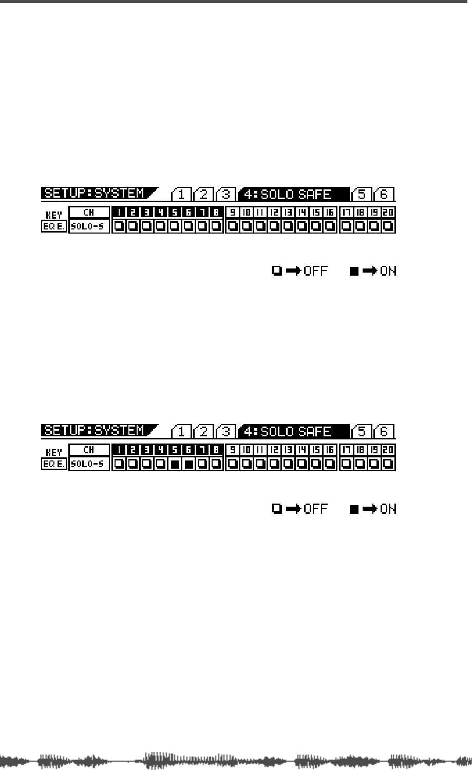
Monitoring Signals
104
VM200 User’s Guide
Solo Safe Function
The VM200 features a Solo Safe function that enables you to desig-
nate specific channels as “solo safe.”
You can monitor solo safe channel signals that are sent to the stereo
buss regardless of the channel’s
[SOLO]
key status. This function is
available when Solo Mode is set to M-Solo (see page 98).
1.
Press the Setup
[SYSTEM]
key four times (from start of cycle).
The VM200 displays the
SETUP:SYSTEM
4:SOLO SAFE
function page. All
[EQ EDIT]
keys flash.
2.
Select the desired channel layer using the
[1–8 ANALOG IN]
,
[9–16 ADAT IN]
, and
[17–20 EFF RTN]
Page Select keys and press
the
[EQ EDIT]
key of the target channels.
The
[EQ EDIT]
keys of the solo safe channels light up, the
[EQ
EDIT]
keys of the non-solo safe channels continue to flash.
The boxes of the solo safe channels are highlighted (dark) on the
display.
In the example above, channels 5 & 6 are designated as “solo
safe” channels. In this case, pressing the channel 1
[SOLO]
key in
M-Solo mode will enable you to monitor not only the channel 1
signal, but also the channels 5 & 6 signals from the stereo buss.
Other channels will be muted.
3.
Press the
[EXIT]
key or the
[CHANNEL/METER]
key to return to
Channel Edit mode.

Metering Signal Levels
VM200 User’s Guide
105
Metering Signal Levels
You can view signal level meters for input Channels 1 through 20 on
the
CHANNEL EDIT/INPUTS
function page. You can display this function
page by pressing the
[CHANNEL/METER]
key.
Press the
[CHANNEL/METER]
key again to display the
CHANNEL EDIT/OUT-
PUTS
function page. This page includes meters for ADAT Outs, Stereo
Buss Out, Rec Buss Out, Aux Sends, and the Effect Sends.
You can also monitor input channel levels for individual channels on
the corresponding
CH VIEW
and
EQ EDIT
function pages. (You can display
these pages by pressing the
[CH VIEW]
key or the corresponding
[EQ
EDIT]
key.)
The
CH VIEW
function page also displays graphic faders and numerical
values to indicate the level of the AUX Sends and the Effect sends. See
“Viewing Individual Channel, Aux Send, and Effect Send Meters” on
page 106 for more information.
You can also meter stereo output levels by watching the dedicated L/R
or St Buss/Solo LED meters, which are located to the right of the LCD
Display.
The LED meters feature overload (OL) indicators, which light up when
signals clip. If this happens, lower the levels. Otherwise the signal
may distort.
Viewing Input/Output Level Meters
1.
Press the
[CHANNEL/METER]
key (or the
[EXIT]
key in most
modes).
The VM200 displays the first
CHANNEL EDIT
page, which features
input level meters.
2.
Press the
[CHANNEL/METER]
button as desired to toggle
between the input level meters and output level meters.
CHANNEL EDIT/INPUT function page (first press of Channel/Meter key)
CHANNEL EDIT/OUTPUT function page (second press of Channel/Meter key)
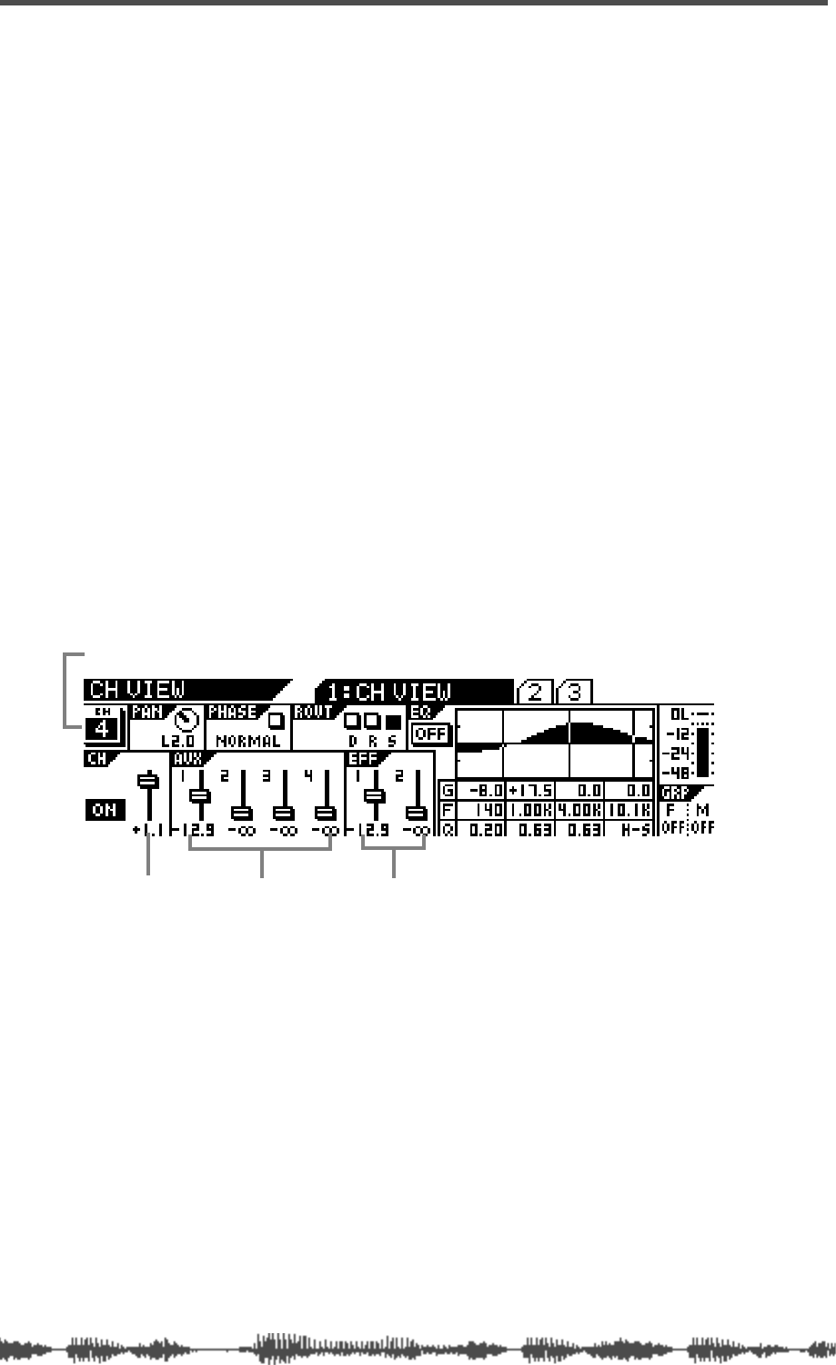
Monitoring Signals
106
VM200 User’s Guide
LED Display Meter (L/R or ST BUSS/SOLO)
The VM200 features two LED meters to the right of the LCD Display
that enable you to view stereo output levels. These nine-segment
LED meters display levels for the left and right channels (L/R) or the
Stereo Buss and soloing channels (St Buss/Solo).
The meters range from –48 dB to OL (overload). The overload indica-
tor lights when the signal clips. If an OL LED lights up while you are
metering levels, reduce the stereo output level to prevent signal dis-
tortion.
Viewing Individual Channel, Aux Send, and Effect Send Meters
1.
Press the [CH VIEW] key.
The VM200 displays the CH VIEW function page. [CH VIEW] key and
all [EQ EDIT] keys flash.
2.
Select a target channel layer by using a Page Select key.
3.
Press the target channel’s [EQ EDIT] key.
The VM200 displays the CH VIEW function page for the corre-
sponding channel.
As you move the faders, notice how the fader icons move to indi-
cate the fader positions.
channel fader level Aux Send level EFF Send level
CH VIEW function page for Channel 4

DIGITAL RECORDING MIXER
VM200
REC BUSS
EFF EDITSELECTED EQ
EQ/HI
EQ/HI-MIDEQ/LO-MID
+10
0
-10
-20
-30
-40
-
+10
0
-10
-20
-30
-40
-
+10
0
-10
-20
-30
-40
-
+10
0
-10
-20
-30
-40
-
+10
0
-10
-20
-30
-40
-
+10
0
-10
-20
-30
-40
-
+10
0
-10
-20
-30
-40
-
GAIN
FREQ
PAN
Q
PAN
ON ON ON ON ON ON ON
SOLO SOLO SOLO SOLO SOLO SOLO SOLO
EQ EDIT EQ EDIT EQ EDIT EQ EDIT EQ EDIT EQ EDIT EQ EDIT EQ EDIT
SOLO
ON ON
SOLO
EQ LIBRARY
STORERECALL
EQ ON
EFF LIBRARY
STORERECALL
EFF2EFF1
RECALLSOLO
EXIT
14
6
13
5
12
4
11
3
2019
FREQ QFREQ Q
Q
GAINGAIN
9-16 ADAT IN 17-20 EFF RTN
P
AGE SELECT
GROUP
PAIR/
METER
CHANNEL/
MIN MAX
+10
0
1
0
1
0
0
-10
-20
-30
-60
-
-40
MMC SEND
PANPANPANPANPANPAN
-40
-36
-24
-18
1212
ST BUSS/SOLO
L R
VM200 User’s Guide
107
CHAPTER 7
Outputs
About This Chapter
This chapter describes the output configurations of the VM200,
including the stereo buss output, the recording buss output, the
ADAT and S/P DIF digital outputs, and the auxiliary (AUX) sends.
Chapter Contents
Overview. . . . . . . . . . . . . . . . . . . . . . . . . . . . . . . . . . . . . . 108
ST BUSS OUT. . . . . . . . . . . . . . . . . . . . . . . . . . . . . . . . 108
REC BUSS OUT . . . . . . . . . . . . . . . . . . . . . . . . . . . . . . 108
ADAT OUT & S/P DIF OUT. . . . . . . . . . . . . . . . . . . . . . 109
AUX SEND . . . . . . . . . . . . . . . . . . . . . . . . . . . . . . . . . . 109
Using the ST BUSS OUT. . . . . . . . . . . . . . . . . . . . . . . . . . 110
Monitoring the ST BUSS OUT. . . . . . . . . . . . . . . . . . . . 110
Viewing the ST BUSS OUT Meters . . . . . . . . . . . . . . . . 110
Soloing the ST BUSS OUT . . . . . . . . . . . . . . . . . . . . . . 111
Setting the ST BUSS OUT Level . . . . . . . . . . . . . . . . . . 111
Muting the ST BUSS OUT. . . . . . . . . . . . . . . . . . . . . . . 111
Using the REC BUSS OUT . . . . . . . . . . . . . . . . . . . . . . . . 112
Monitoring the REC BUSS OUT . . . . . . . . . . . . . . . . . . 112
Viewing the REC BUSS OUT Meters . . . . . . . . . . . . . . . 112
Soloing the REC BUSS OUT . . . . . . . . . . . . . . . . . . . . . 113
Setting the REC BUSS OUT Level . . . . . . . . . . . . . . . . . 113
Using the AUX Sends . . . . . . . . . . . . . . . . . . . . . . . . . . . . 115
Enabling AUX Sends 3 & 4 (ADD. AUX Parameter) . . . . 115
Monitoring AUX Sends . . . . . . . . . . . . . . . . . . . . . . . . . 116
Viewing the AUX Send and Master Setting . . . . . . . . . . 116
Sending Channel Signals to AUX Sends . . . . . . . . . . . . 117
Pre-fader/Post-fader AUX Sends. . . . . . . . . . . . . . . . . . 117
Muting AUX Sends . . . . . . . . . . . . . . . . . . . . . . . . . . . . 118
Pairing AUX Sends . . . . . . . . . . . . . . . . . . . . . . . . . . . . 119
Smoothing Function. . . . . . . . . . . . . . . . . . . . . . . . . . . 120
Viewing Buss Routing for Each Channel . . . . . . . . . . . . . 121
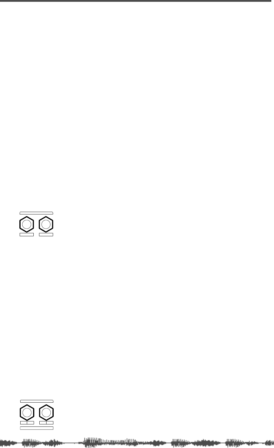
Outputs
108
VM200 UserÕs Guide
Overview
The VM200 features several types of outputs, including the stereo
buss output, the recording buss output, the ADAT and S/P DIF dig-
ital outputs, and auxiliary (AUX) and effect (EFF) sends.
You can control much of the signal routing by setting parameters on
the
ROUTING
function page. You can display the
ROUTING
function page
by pressing the [ROUTING/PHASE] key.
The Effect Send capabilities of the VM200 are explained in more
detail in the “Effects” chapter page 123.
ST BUSS OUT
The VM200 converts the digital stereo buss (ST BUSS) signal to an
analog signal using 20-bit 128-times oversampling D/A converters.
It then outputs it from the ST BUSS OUT unbalanced phone jack
(located on the rear panel) with a –10 dB nominal output level.
To output signals from these connectors, you need to route channel
signals to ST BUSS using the
ROUTING
function page, which you can
access by pressing the
[ROUTING/PHASE]
key. (See “Input Channels”
on page 59.)
For more information, see “Using the ST BUSS OUT” on page 110.
REC BUSS OUT
The VM200 converts the digital stereo signal output from the REC
BUSS to an analog signal using 20-bit 128-times oversampling D/A
converters. The analog signal is then output from the rear panel via
the REC BUSS OUT unbalanced phone jacks with a –10 dB nominal
output level.
To output signals from these connectors, you need to route channel
signals to REC BUSS using the
ROUTING
function page accessed via
the [ROUTING/PHASE] key. (See “Input Channels” on page 59.)
The signals from the REC BUSS are also routed to input channels
1–8. More specifically, the left channel signals are routed to channels
1, 3, 5, and 7, and the right channel signals are routed to channels
2, 4, 6, and 8. You can then route the signals directly to the ADAT
OUTS 1–8. In this way, you can output two mixes simultaneously.
For more information, see “Using the REC BUSS OUT” on page 112.
RL
ST BUSS OUT
ST BUSS OUT
R4 L3
ADD.AUX SEND
REC BUSS OUT
REC BUSS OUT
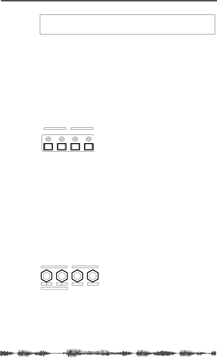
ADAT OUT & S/P DIF OUT
VM200 User’s Guide
109
ADAT OUT & S/P DIF OUT
You can output digital stereo signals from the ADAT OUT and S/P
DIF OUT connectors.
You can connect any ADAT-compatible recording device to the ADAT
OUT optical connector, including a Fostex VR800 recorder, Alesis®
ADAT, Alesis ADAT-XT, or other digital multitrack recorders.
The S/P DIF OUT uses an optical connector. You can use this to route
the stereo signal to any S/P DIF format audio device, such as a com-
puter soundcard or DAT recorder.
For more information, see “Digital Connections” on page 159.
AUX SEND
You can assign a signal to AUX Sends 1 through 4. (AUX Sends 3 & 4
are available only when the ADD. AUX parameter is turned on. For
more information, see “Enabling AUX Sends 3 & 4 (ADD. AUX
Parameter)” on page 115.)
The AUX Sends provide additional outputs that you can use for a vari-
ety of purposes. For example, you can route a signal out the AUX
SENDS to an external DAT recorder, talkback system, or other appli-
cation.
You can configure channel AUX Sends as pre-fader or post-fader
sends.
For more information, see “Using the AUX Sends” on page 115.
Note:
If the ADD. AUX parameter is turned on, the REC BUSS is
disabled. Fore more information, see “Enabling AUX Sends 3 & 4
(ADD. AUX Parameter)” on page 115.
IN OUT
ADAT
OUTIN
S/P DIF
ADAT and S/P DIF connections
R4 L3 2 1
ADD.AUX SEND
AUX SENDREC BUSS OUT
AUX Sends 1–4
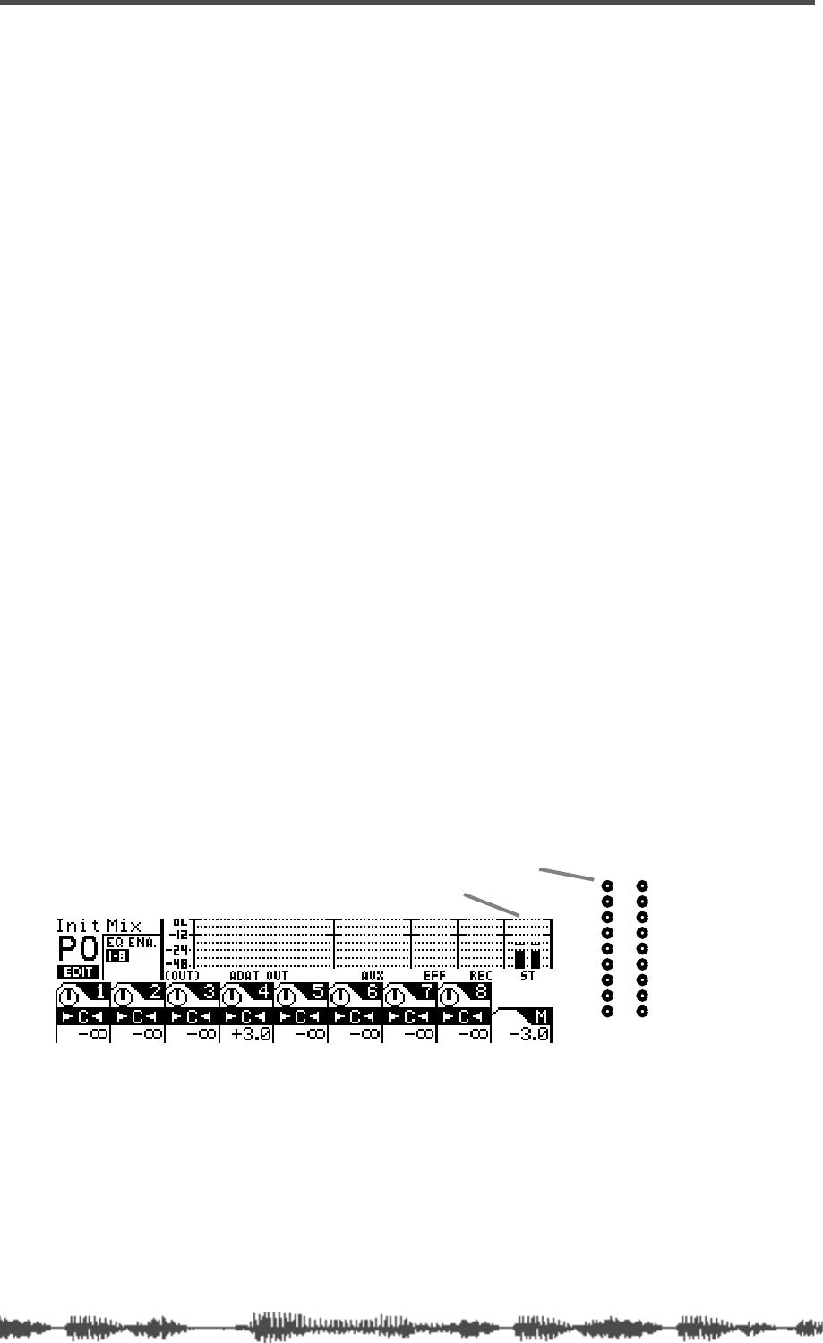
Outputs
110
VM200 UserÕs Guide
Using the ST BUSS OUT
The VM200 converts the ST BUSS stereo digital signal to analog
using 20-bit 128-times oversampling D/A converters. The analog sig-
nal is then output from the ST BUSS OUT connectors on the rear
panel. These connectors are unbalanced phone jacks with a –10 dB
nominal output level.
The same ST BUSS stereo digital signal is also converted to an S/P
DIF signal via the S/P DIF encoder and output from the S/P DIF OUT
connector on the rear panel. (For more information, see “Using S/P
DIF OUT” on page 168.)
In a typical recording setup, you could use the ST BUSS OUT for mas-
ter recording.
Monitoring the ST BUSS OUT
You can monitor the ST BUSS OUT signal by connecting the MONI-
TOR OUT jacks to an amplifier and speakers. Set the Mon Sel (Mon-
itor Select) parameter on the
SETUP:SYSTEM 1:CLOCK/MON
function page
to “ST-B” (stereo buss) (see page 98).
You can also monitor the ST BUSS OUT signal through a pair of ste-
reo headphones connected to the PHONES jack. For more informa-
tion, see “Monitoring Signals” on page 97.
Viewing the ST BUSS OUT Meters
You can view the stereo output signal levels on the nine-segment
L/R Stereo/Solo LED meters.
You can also view the stereo output level on meters that appear on
the
CHANNEL EDIT/OUTPUTS
function page, which you can display by
pressing the
[CHANNEL/METER]
key twice.
See the “Monitoring Signals” on page 97 for more information.
ST BUSS OUT level
-48
-36
-24
-18
-12
-9
-6
-3
OL
ST BUSS/SOLO
LR
METER
LED meters
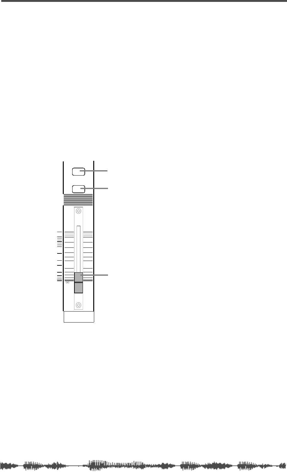
Soloing the ST BUSS OUT
VM200 User’s Guide
111
Soloing the ST BUSS OUT
You can solo the signal output from the ST BUSS by pressing the
[SOLO]
key on the Master channel. The Master
[SOLO]
key lights up.
The Master
[SOLO]
key works only when Solo mode is set to PFL,
which is the default setting. If Solo mode is set to M-Solo, the Master
[SOLO]
key is disabled. For more information on Solo mode, see
page 101.
If you set the Solo Key parameter to LATCH, pressing the
[SOLO]
key
solos the stereo output until you press the
[SOLO]
key again. If the
parameter is set to UNLATCH, the stereo output will solo only until
you release the Master
[SOLO]
key.
Setting the ST BUSS OUT Level
You control the stereo output level using the Master fader.
Since the Master fader can also con-
trol the Aux and Effects Send master
levels, depending on the Fader Mode,
you need to press the
[CHANNEL]
key
before you can adjust the stereo out-
put level. This places the VM200 in
Channel Fader Mode, enabling the
Master fader to control the stereo out-
put level.
See “Faders” on page 32 for more
information.
Muting the ST BUSS OUT
You can mute the stereo output by
turning off the
[ON]
key for the Mas-
ter channel. The
[ON]
key lights up
when stereo output is on. Turning
off
the
[ON]
key mutes the stereo buss
output.
Since the Master
[ON]
key can also mute the Aux and Effects Send
master outputs, depending on the Fader Mode, you may need to press
the
[CHANNEL]
key to place the VM200 in Channel Fader Mode before
you can mute the stereo buss output.
This places the VM200 in Channel Fader Mode, enabling the Master
[ON]
key to mute the stereo output.
See “[ON] Keys” on page 34 for more information.
ON
SOLO
MASTER
0
-10
-20
-30
-60
-
-40
Master SOLO key
Master ON key
Master Fader
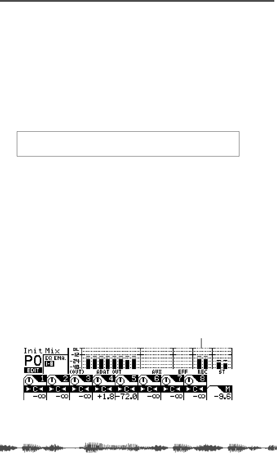
Outputs
112
VM200 UserÕs Guide
Using the REC BUSS OUT
The VM200 converts the REC BUSS stereo signal to analog using
20-bit 128-times oversampling D/A converters. The analog signal is
then output from the REC BUSS OUT connectors on the rear panel.
These connectors are unbalanced phone jacks with a –10 dB nominal
output level.
The REC BUSS also sends the left signal to channels 1, 3, 5, and 7,
and the right signal to channels 2, 4, 6, and 8 so that you can route
them to ADAT OUT 1–8 directly. This configuration enables you to
send two mixes to two different external recorders at the same time
(assuming one recorder is ADAT-compatible). (For more information
on ADAT OUT connections, see “Digital Connections” on page 159.)
Monitoring the REC BUSS OUT
You can monitor the REC BUSS OUT signal by connecting the MON-
ITOR OUT jacks to an amplifier and speakers. Set the Mon Sel (Mon-
itor Select) parameter on the
SETUP:SYSTEM 1:CLOCK/MON
page to
“REC-B” (see page 98).
You can also monitor the REC BUSS OUT signal through a pair of ste-
reo headphones connected to the PHONES jack. For more informa-
tion, see “Monitoring Signals” on page 97.
Viewing the REC BUSS OUT Meters
You can view the REC BUSS OUT level on meters that appear on the
CHANNEL EDIT/OUTPUTS
function page. You can display this function
page by pressing the
[CHANNEL/METER]
key twice.
See the “Monitoring” chapter on page 97 for more information.
Note:
If the ADD. AUX parameter is on, the REC BUSS is disabled.
Fore more information, see “Enabling AUX Sends 3 & 4 (ADD. AUX
Parameter)” on page 115.
REC BUSS OUT meter

Soloing the REC BUSS OUT
VM200 User’s Guide
113
Soloing the REC BUSS OUT
You can solo the signal output from the REC BUSS by pressing the
REC BUSS
[SOLO]
key (located next to the Master
[SOLO]
key). The
Rec Buss
[SOLO]
key lights up. The Rec Buss
[SOLO]
key works only
when Solo mode is set to PFL, which is the default setting. If Solo
mode is set to M-Solo, the Rec Buss
[SOLO]
key is disabled. For more
information on Solo mode, see page 101.
If you set the Solo Key parameter to LATCH, pressing the Rec Buss
[SOLO]
key solos the stereo output until you press the Rec Buss
[SOLO]
key again. If the parameter is set to UNLATCH, the Rec Buss output
will solo only until you release the Rec Buss
[SOLO]
key.
Setting the REC BUSS OUT Level
You can set the Rec Buss output level on the
CURRENT SCENE STATUS
function page.
1.
Press the
[CURRENT SCENE STATUS]
key.
The VM200 displays the
CURRENT SCENE STATUS
function page.
2.
Rotate the EQ/HI Gain rotary control (channels 7/8) to adjust
the REC-B GAIN parameter.
The REC-B GAIN parameter controls the Rec Buss Out level.
REC BUSS
SOLO REC BUSS SOLO key
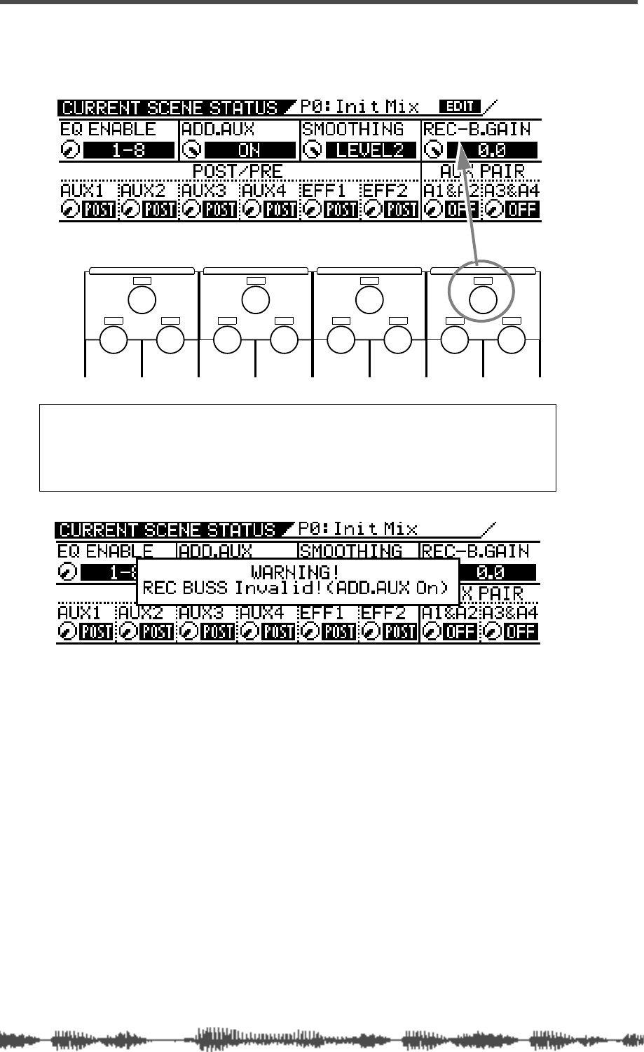
Outputs
114
VM200 UserÕs Guide
You can adjust the level (-
∞
, -90 to 0dB) in 128 increments. The
default setting is 0dB.
Note:
If you try to operate the Gain rotary control while the ADD.AUX
parameter is turned ON, the VM200 displays a warning message and you
will be unable to adjust the REC-B Gain. Use the EQ/LO-MID Gain rotary
control (channels 3/4) to turn off the ADD.AUX parameter on the
CURRENT
SCENE STATUS
function page.
EQ/HI
EQ/HI-MIDEQ/LO-MIDEQ/LO
GAIN
FREQ
PAN
Q
PAN
FREQ QFREQ Q
FREQ Q
GAINGAINGAIN
PANPANPANPANPANPAN
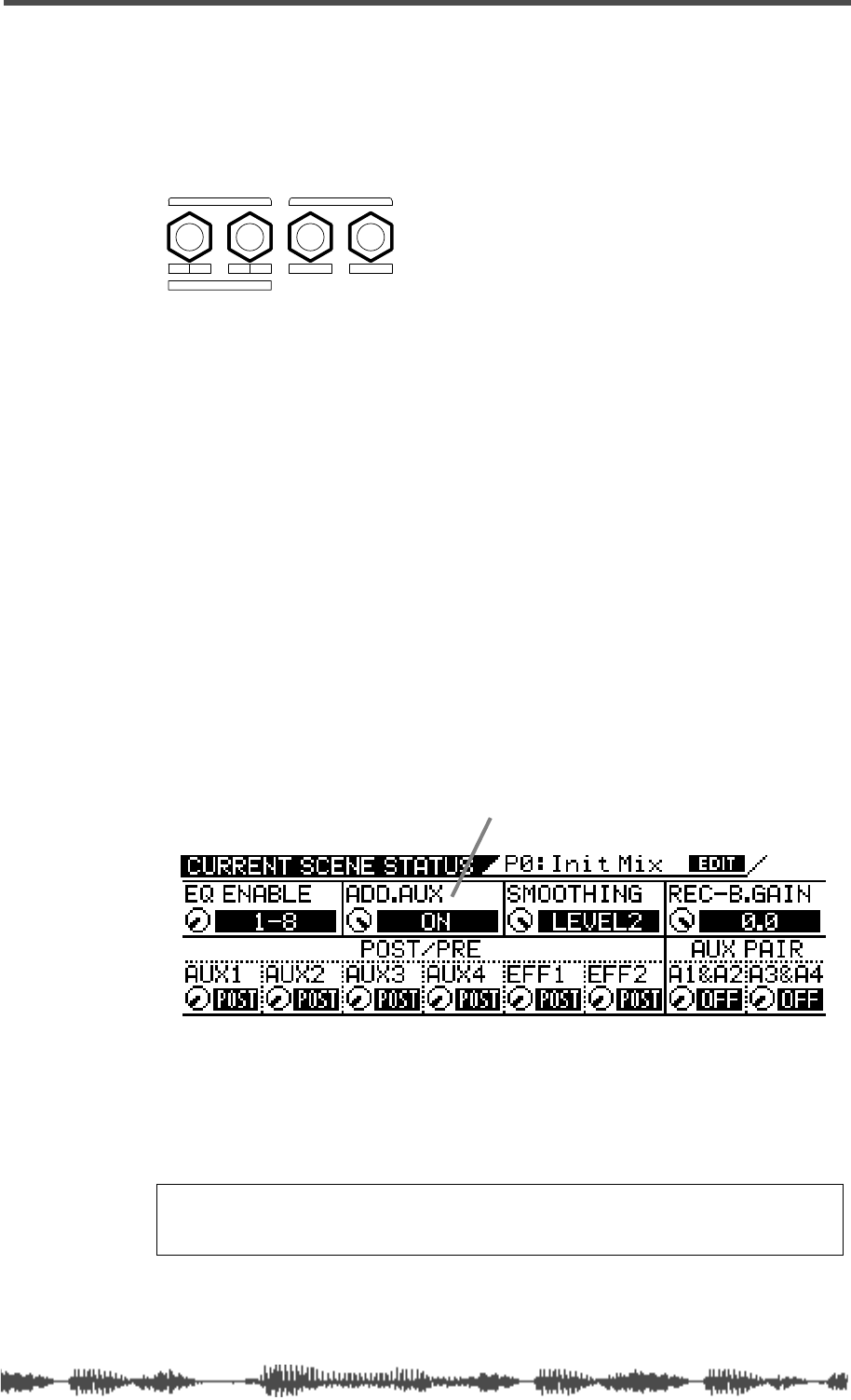
Using the AUX Sends
VM200 User’s Guide
115
Using the AUX Sends
The VM200 features four auxiliary (AUX) sends, which enable you to
send a signals to various destinations. You can send signals from
input channels 1 through 20 to AUX Sends 1 through 4. You can use
the four AUX Sends individually or in stereo pairs.
You can configure each channel AUX Send as a pre-fader or
post-fader send.
AUX Sends 1 through 4 signals are routed to the AUX SEND 1
through 4 jacks respectively. (AUX 3 & 4 are available only if you turn
on the ADD.AUX parameter, as described below.)
The VM200 also features a Smoothing function that reduces CPU load
to achieve smoother fader adjustment.
The VM200 does not include dedicated AUX return inputs. Use the
insert channels to return AUX signals. For more information, see
“Insert Channels 1–4” on page 62.
Enabling AUX Sends 3 & 4 (ADD. AUX Parameter)
If you wish to use AUX Sends 3 & 4, you must turn on the ADD. AUX
parameter on the
CURRENT SCENE STATUS
function page.
1.
Press the
[CURRENT SCENE STATUS]
key.
The VM200 displays the
CURRENT SCENE STATUS
function page.
2.
Rotate the EQ/LO-MID Gain control to turn on the ADD.AUX
parameter.
The ON indicator in the ADD. AUX parameter field flashes.
3.
Press the
[ENTER]
key to confirm the change.
4.
Press the
[EXIT]
key to display the
CHANNEL EDIT
function page.
Note:
When the ADD.AUX parameter is turned on, the REC BUSS OUT
jacks function as AUX Sends 3 and 4, and the REC BUSS OUT routing
is disabled.
R4 L3 2 1
ADD.AUX SEND
AUX SENDREC BUSS OUT
AUX Sends 1–4
ADD.AUX parameter
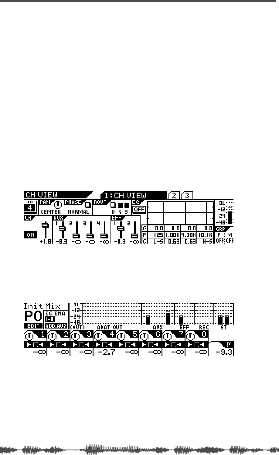
Outputs
116
VM200 UserÕs Guide
Monitoring AUX Sends
You can monitor the REC BUSS OUT signal by connecting the MON-
ITOR OUT jacks to an amplifier and speakers. Set the Mon Sel (Mon-
itor Select) parameter on the
1:CLOCK/MON
page to AUX1, AUX2,
AUX3, or AUX4 (see page 98).
You can also monitor the REC BUSS OUT signal through a pair of ste-
reo headphones connected to the PHONES jack. For more informa-
tion, see “Monitoring Signals” on page 97.
Viewing the AUX Send and Master Setting
You can view the AUX Send level and send master level on meters
that appear on the
CH VIEW
function page and the Channel Edit/Out-
puts function page respectively.
To view the AUX Send level, press the
[CH VIEW]
key to display the
1:CH VIEW
function page, press a Page Select key to select the desired
channel layer, and press the
[EQ EDIT]
key for the Aux Send channel.
You can display the
CHANNEL EDIT/OUTPUTS
function page to view the
AUX Send master level by pressing the
[CHANNEL/METER]
key twice.
See “Monitoring Signals” on page 97 for more information.
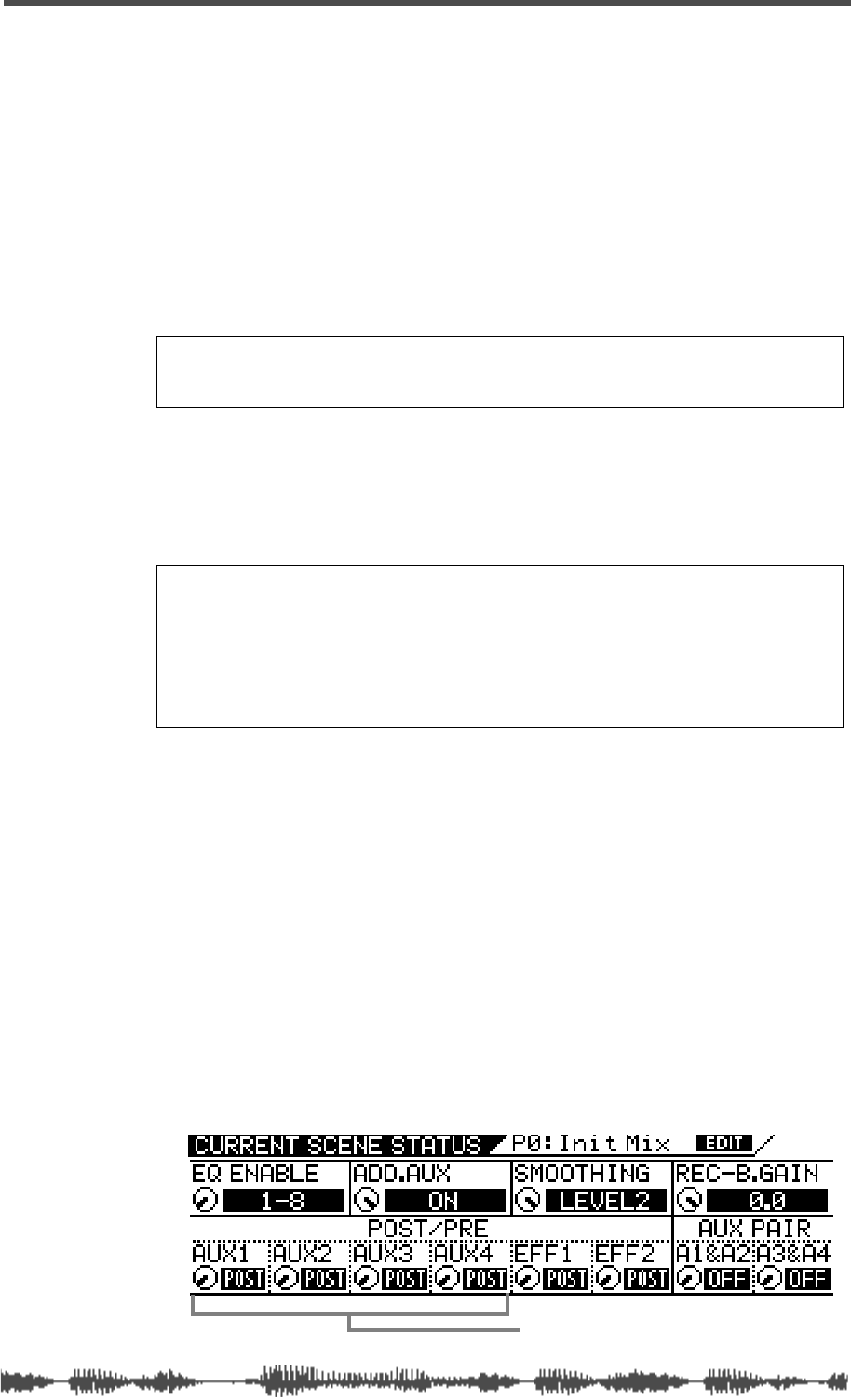
Sending Channel Signals to AUX Sends
VM200 User’s Guide
117
Sending Channel Signals to AUX Sends
You can send signals from input channels 1 through 20 to AUX Sends
1 through 4.
If the AUX Send is configured post-fader (see “Pre-fader/Post-fader
AUX Sends” below), first raise the channel’s regular fader l prior to
step 1 by pressing the
[CHANNEL]
button, and then raising the fader.
1.
In the Fader Mode section, press the
[AUX1], [AUX2], [AUX3]
, or
[AUX4]
key to select an AUX Send.
The faders now function as channel AUX Send controls for the
selected AUX Send.
2.
Raise the fader of the channel you want to send to the AUX
Send.
3.
Use the Master fader to adjust the AUX Sends master level.
When channels are configured as stereo pairs their AUX Send
controls are linked. (See “Pairing Channels” on page 68).
Pre-fader/Post-fader AUX Sends
You can configure each AUX Send as pre-fader or post-fader by
adjusting parameters on the
CURRENT SCENE STATUS
function page.
Pre-fader signals do not pass through the channel faders and are
therefore unaffected by channel fader settings. Post-fader signals
pass through the channel faders and are affected by channel fader
settings.
Follow these steps to configure each AUX Send as pre-fader or
post-fader.
1.
Press the
[CURRENT SCENE STATUS]
key.
The VM200 displays the
CURRENT SCENE STATUS
function page.
Note:
If the ADD. AUX parameter is on, the REC BUSS is disabled. Fore
more information, see “Enabling AUX Sends 3 & 4 (ADD. AUX Parame-
ter)” on page 115.
Note:
If the Smoothing function is set to Level 2 (default), AUX1 and EFF1
are linked, and AUX2 and EFF2 are linked. Therefore, setting the AUX1
level also sets EFF1 to the same level; similarly, setting the AUX2 level
sets EFF2 to the same level. If the Smoothing function is set to Level 1,
you may hear a slight stepping noise when you move the fader. For more
information on the Smoothing function, see “Smoothing Function” on
page 120.
pre-fader/post-fader AUX Sends
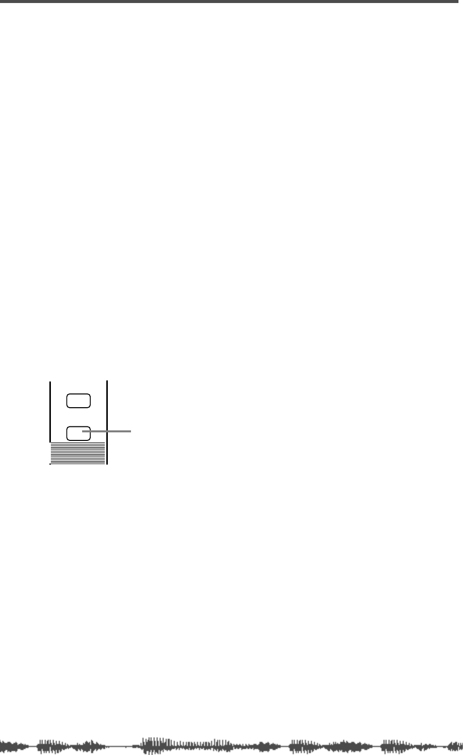
Outputs
118
VM200 UserÕs Guide
2.
Use the Freq and Q rotary controls for channels 1–4 to select
PRE or POST for AUX1, AUX2, AUX3, and AUX4.
The default setting is POST.
When you change the setting, the selected value flashes.
3.
Press the
[EXIT]
key to display the
CHANNEL EDIT
function page.
Muting AUX Sends
You can mute the AUX Send Masters by turning off the [ON] key for
the Master channel.
Since the Master
[ON]
key can also mute the Stereo Buss and Effects
Send master outputs, depending on the Fader Mode, you need to
press the
[AUX1], [AUX2], [AUX3]
, or
[AUX4]
key to select an AUX Send
before you can mute it.
1.
Press the
[AUX1], [AUX2], [AUX3]
, or
[AUX4]
key to select an AUX
Send.
The selected AUX key flashes.
2.
Use the MASTER
[ON]
button to turn the AUX Send on and off.
When AUX Sends are configured as stereo pairs, their
[ON]
buttons
are linked (see “Pairing Channels” on page 68).
See “[ON] Keys” on page 34 for more information.
ON
SOLO
Master ON key
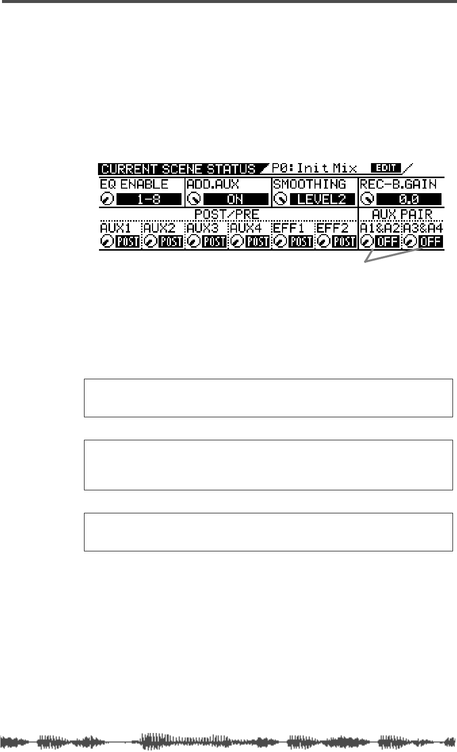
Pairing AUX Sends
VM200 UserÕs Guide
119
Pairing AUX Sends
You can pair AUX Sends 1 and 2 and AUX Sends 3 and 4 for stereo
signal processing.
When paired, the Master Faders,
[ON]
keys, and monitors of each AUX
Send are set the same and linked for simultaneous control.
Follow these steps to pair AUX Sends:
1.
Press the
[CURRENT SCENE STATUS]
key.
The VM200 displays the
CURRENT SCENE STATUS
function page.
2.
Use the Freq and Q rotary controls for channels 7/8 to turn
the A1&A2 and A3&4 parameters On or Off.
The default setting is “off.”
If you change the parameter setting, the indicator flashes.
3.
Press the
[EXIT]
key to return to Channel Edit mode.
Note:
If the ADD. AUX parameter is on, the REC BUSS is disabled. For
more information, see “Enabling AUX Sends 3 & 4 (ADD. AUX Parame-
ter)” on page 115.
Note:
When AUX1 and 2 are paired, the AUX1 signal is sent to the left
channel and AUX2 signal is sent to the right. Similarly, when AUX3 and
4 are paired, the AUX3 signal is sent to the left channel and the AUX4
signal is sent to the right channel.
Note:
If the Smoothing function is set to Level 2 (default), the AUX pair
setting will affect the EFF pair setting. For more information on the
Smoothing function, see “Smoothing Function” on page 120.
AUX PAIR parameters
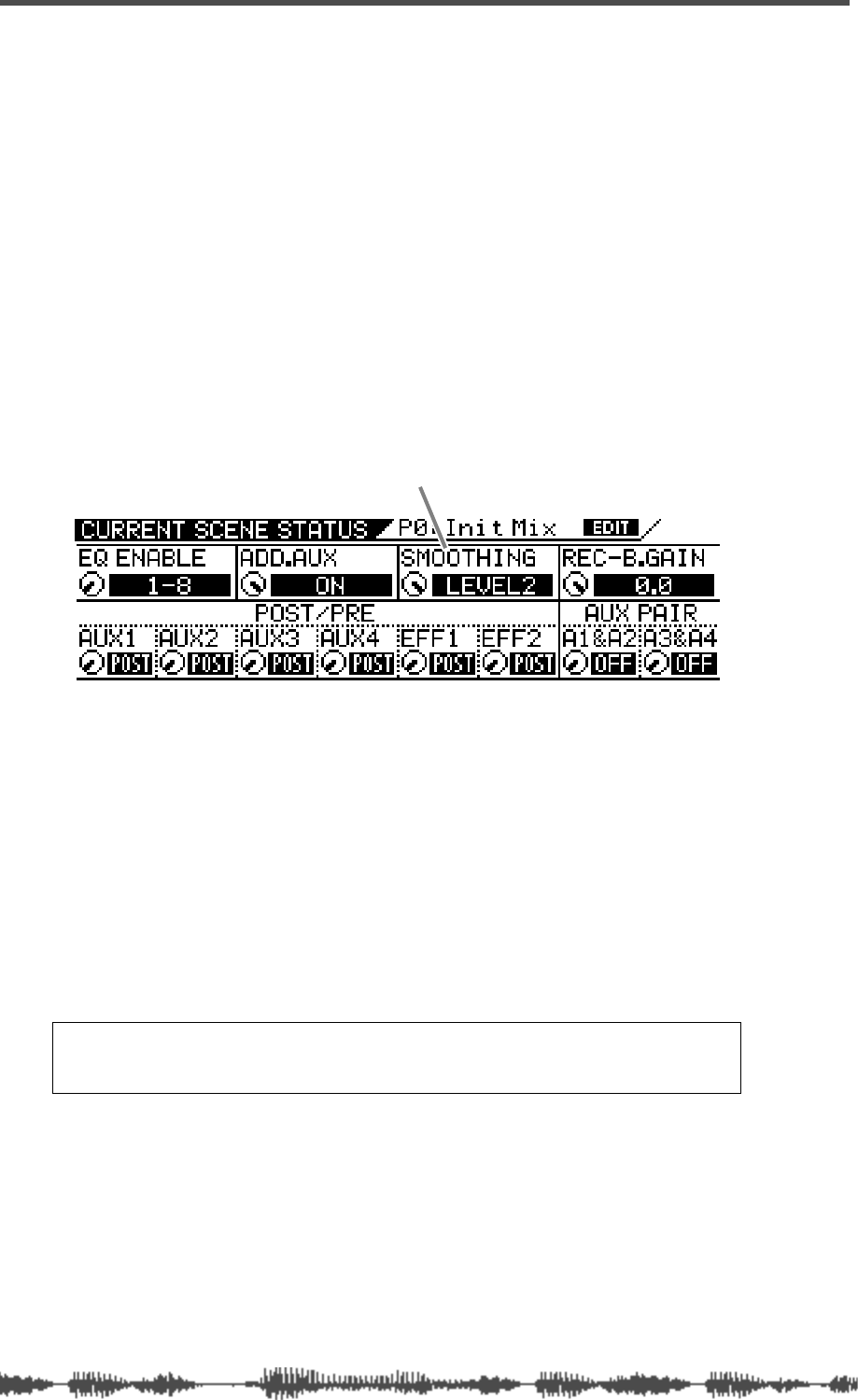
Outputs
120
VM200 UserÕs Guide
Smoothing Function
Depending on the sound you are mixing, you may hear a slight step-
ping noise when you slide the faders. This indicates an overloaded
CPU. To resolve this problem, the VM200 features a Smoothing func-
tion that reduces CPU load to achieve smoother fader adjustment.
When the Smoothing function is set to Level 2, AUX1 and EFF1 are
linked and AUX2 and EFF2 are linked. Therefore, the level settings,
pair settings, and pan settings for AUX Send 1 and AUX Send 2 will
be applied to the level settings, pair settings, and pan settings for
EFF1 and EFF2. However, fader operation will be much finer.
Follow the steps below to set the Smoothing function. The default set-
ting is Smoothing “LEVEL 2.”
1.
Press the
[CURRENT SCENE STATUS]
key.
The VM200 displays the
CURRENT SCENE STATUS
function page.
2.
Use the EQ/HI-MID Gain rotary control to toggle between
Level1 and Level2.
Level 1: AUX Sends 1/2 and EFF Sends 1/2 are not linked, but
the faders’ smoothing function may be coarse, and depending on
the sound, you may hear a slight stepping noise when you slide
the faders in AUX Send mode.
Level 2: AUX Send 1 and EFF Send 1 are linked, and AUX Send 2
and EFF Send 2 are linked. The level settings, pair setting, and
pan setting for AUX Send 1 and AUX Send 2 will be applied to the
level settings, pair settings, and pan settings for EFF1 and EFF2.
However, fader operation will be much smoother and you should
not hear any noise.
3.
Press the
[ENTER]
key to confirm the setting.
Note:
If the EQ Enable parameter in the
CURRENT SCENE STATUS
page is set
to “1–16,” the Smoothing function remains Level 2 even if you can change
to Level 1 on the display.
Smoothing parameter
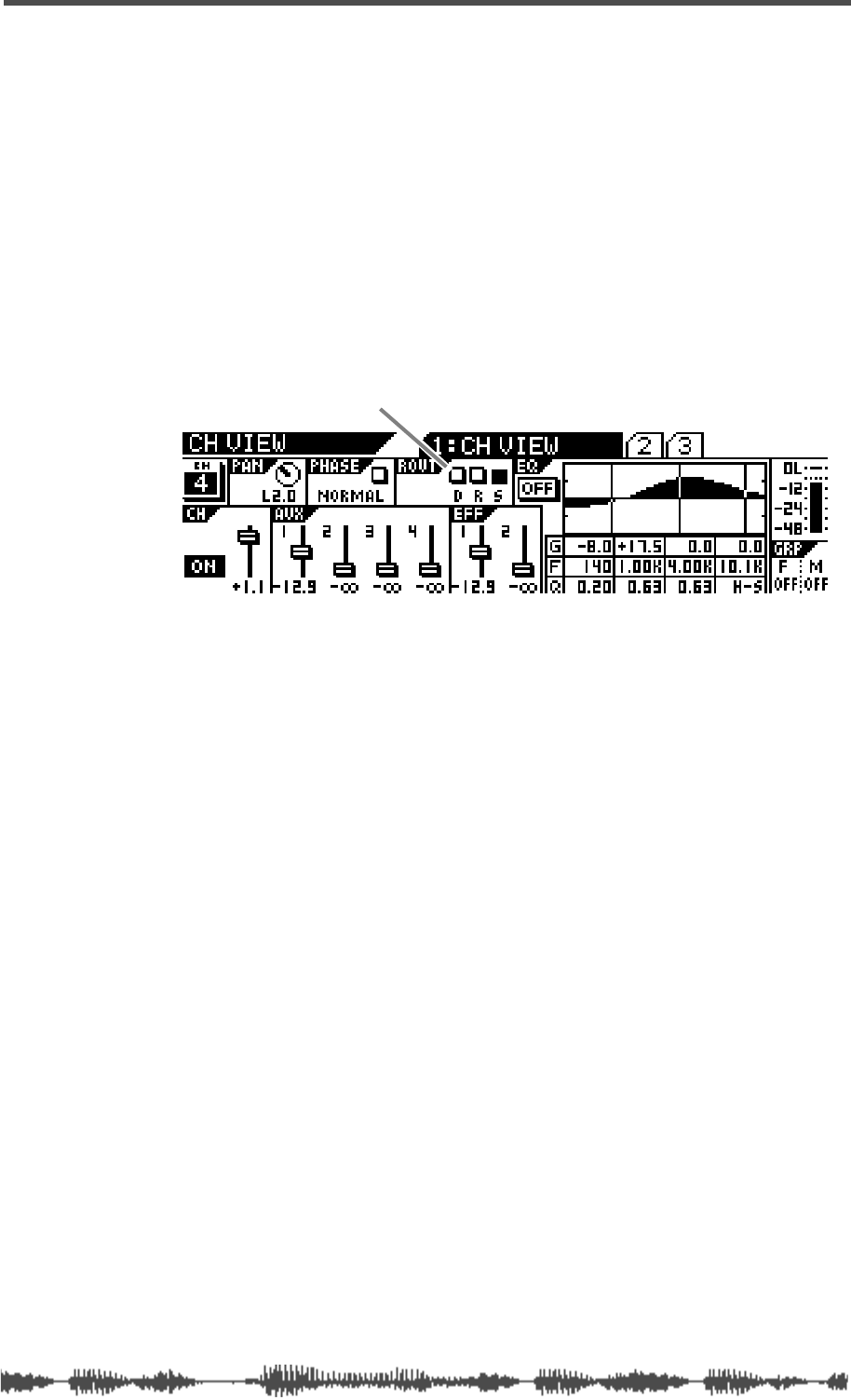
Viewing Buss Routing for Each Channel
VM200 User’s Guide 121
Viewing Buss Routing for Each Channel
The CH VIEW function page includes a ROUT display that indicates
whether the specified channel is routed to the ADAT Direct Outs, the
Stereo Buss, or the Record Buss.
1. Press the [CH VIEW] key.
2. Press the [EQ EDIT] key for the desired channel.
The VM200 displays the 1:CH VIEW function page, which includes
the ROUT indicator in the top center of the display.
The D, R, and S indicators represent the ADAT Direct Outs, the
Record Buss, and the Stereo Buss. A highlighted (dark) indicator
means the channel is being sent to the specified buss.
ROUT D, R, S indicator

Outputs
122 VM200 User’s Guide

DIGITAL RECORDING MIXER
VM200
REC BUSS
EFF EDITSELECTED EQ
EQ/HI
EQ/HI-MIDEQ/LO-MID
+10
0
-10
-20
-30
-40
-
+10
0
-10
-20
-30
-40
-
+10
0
-10
-20
-30
-40
-
+10
0
-10
-20
-30
-40
-
+10
0
-10
-20
-30
-40
-
+10
0
-10
-20
-30
-40
-
+10
0
-10
-20
-30
-40
-
GAIN
FREQ
PAN
Q
PAN
ON ON ON ON ON ON ON
SOLO SOLO SOLO SOLO SOLO SOLO SOLO
EQ EDIT EQ EDIT EQ EDIT EQ EDIT EQ EDIT EQ EDIT EQ EDIT EQ EDIT
SOLO
ON ON
SOLO
EQ LIBRARY
STORERECALL
EQ ON
EFF LIBRARY
STORERECALL
EFF2EFF1
RECALLSOLO
EXIT
14
6
13
5
12
4
11
3
2019
FREQ QFREQ Q
Q
GAINGAIN
9-16 ADAT IN 17-20 EFF RTN
P
AGE SELECT
GROUP
PAIR/
METER
CHANNEL/
MIN MAX
+10
0
1
0
1
0
0
-10
-20
-30
-60
-
-40
MMC SEND
PANPANPANPANPANPAN
-40
-36
-24
-18
1212
ST BUSS/SOLO
L R
VM200 User’s Guide
123
CHAPTER 8
Effects
About This Chapter
This chapter describes how to apply the VM200 internal effects to
the signals, and how to recall, store, and edit the programs in the
Effects library.
This chapter also includes a complete effects parameter list.
Chapter Contents
VM200 Effects . . . . . . . . . . . . . . . . . . . . . . . . . . . . . . . . . 124
Effects Library . . . . . . . . . . . . . . . . . . . . . . . . . . . . . . . . . 125
Effect Preset Library List. . . . . . . . . . . . . . . . . . . . . . . . . . 125
Applying Effects . . . . . . . . . . . . . . . . . . . . . . . . . . . . . . . . 128
Selecting an Effects Processor. . . . . . . . . . . . . . . . . . . . 128
Setting Effects Return. . . . . . . . . . . . . . . . . . . . . . . . . . 128
Sending Signal to Effects Processor . . . . . . . . . . . . . . . 129
Routing Effects Returns . . . . . . . . . . . . . . . . . . . . . . . . 129
Controlling the Sends Signals. . . . . . . . . . . . . . . . . . . . 130
Pre-fader/Post-fader Effect Sends. . . . . . . . . . . . . . . . . 130
Viewing and Adjusting the Effect Send Level. . . . . . . . . 130
Viewing and Adjusting the Effect Send Master Level . . . 131
Muting Effect Sends . . . . . . . . . . . . . . . . . . . . . . . . . . . 132
Monitoring Effects Sends . . . . . . . . . . . . . . . . . . . . . . . 132
Controlling the Return Signals . . . . . . . . . . . . . . . . . . . . . 132
Setting the Effect Return Level . . . . . . . . . . . . . . . . . . . 132
Panning Effects Returns. . . . . . . . . . . . . . . . . . . . . . . . 132
Effects Library . . . . . . . . . . . . . . . . . . . . . . . . . . . . . . . . . 133
Editing Effects . . . . . . . . . . . . . . . . . . . . . . . . . . . . . . . . . 133
Recalling Effects Programs . . . . . . . . . . . . . . . . . . . . . . . . 134
Storing Effects Programs . . . . . . . . . . . . . . . . . . . . . . . . . 135
Editing Effect Program Titles . . . . . . . . . . . . . . . . . . . . . . 137
Effects Parameters . . . . . . . . . . . . . . . . . . . . . . . . . . . . . . 139
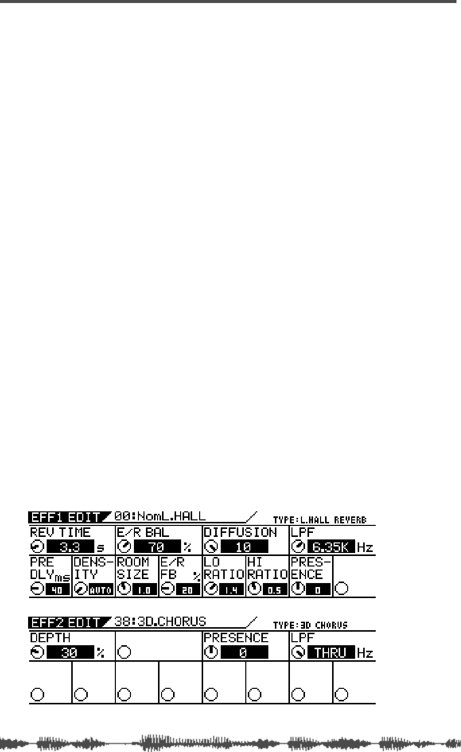
Effects
124
VM200 User’s Guide
VM200 Effects
The VM200 features two on-board stereo multi-effects processors
(EFF1, EFF2) that provide a wide range of high-quality effects, includ-
ing reverbs, delays, choruses, flangers, and more.
These internal effect processors use A.S.P. (Fostex Advanced Signal
Processing Technology, developed exclusively by Fostex). This tech-
nology extracts maximum efficiency from limited DSP power. It
achieves an overwhelmingly high-density Early Reflection sound and
a smooth High Dump response through the application of H.F.A.
(Harmonic Feedback Algorithm). Furthermore, it carries out an elab-
orate reverb simulation to create clear sounds through H.D.L.P.
(Hi-Density Logarithmic Processing), which eliminates the mutual
interference between the numerous integrated delay modules and
reduces sonic impurities and “grit.”
The VM200 includes an Effects Library that contains 50 Preset pro-
grams and 50 User programs. See the “Effects Library” on page 125
for more information.
You can recall and edit any Preset or User program to create a new
effect, then store it in any User program location.
You can load different effect programs to processors EFF1 and EFF2
and route signals through either as desired.
To recall an effect, press the EFF1 or EFF2 to specify the processor
you wish to use. Then press the Recall key and select the effect from
the library. (See “Recalling Effects Programs” on page 134.)
To edit an effect, press the EFF1 or EFF2 key to display the
EFF1
or
EFF2
function pages, which include the name and number of the
selected effect and a set of parameters associated with the effect. You
can adjust the parameters using the rotary controls (Gain, Freq, Q).
(See “Editing Effects” on page 133.)
Effect busses 1 and 2 feed effects processors 1 and 2 respectively.
Processed signals return to channels 17–20.
You may apply effects to input channels 1–20.
You can also store effects selection in Scene Memory.
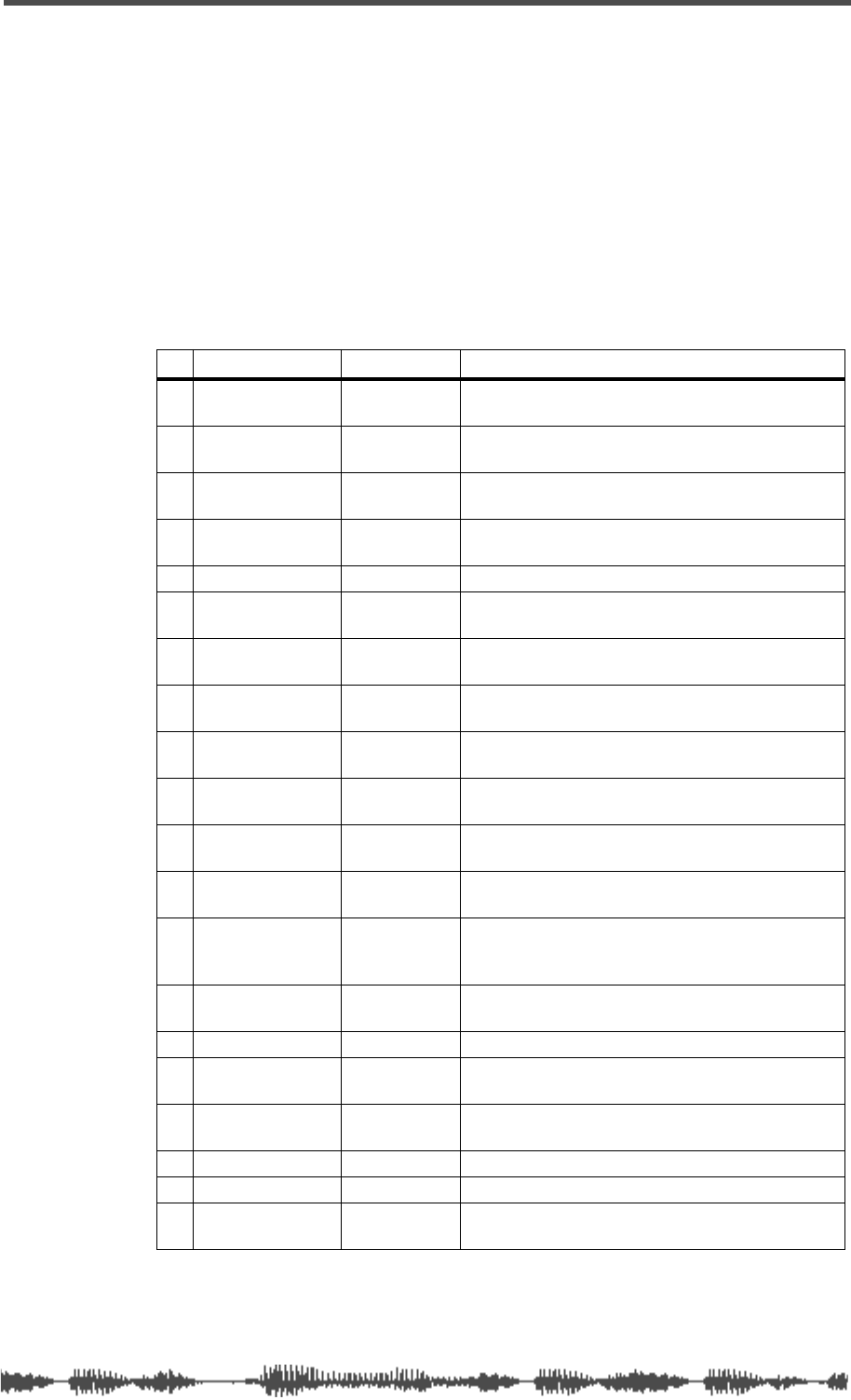
Effects Library
VM200 User’s Guide
125
Effects Library
The VM200 also includes an Effects Library that contains 50 Preset
programs and 50 User programs.
Effect Preset Library List
The following table lists the Preset effect programs. See “Effects
Parameters” on page 139 for detailed parameter information.
Reverb effects
# Name Display Description
00 Normal Large
Hall NomL.Hall Conventional large hall, with sonic detail, clarity,
and an appropriate amount of early reflections.
01 Lo-Freq Large
Hall LowL.Hall Large hall with lingering low-frequency reverb
components.
02 Presence Large
Hall PrsL.HALL Reverb with crispness and good presence.
03 Wet Large Hall WetL.HALL Reverb with restrained high-frequency range and
gentle character.
04 Stadium STADIUM Stadium reverb with many long early reflections.
05 Normal Small
Hall NomS.Hall Conventional small hall, with sonic detail, clarity,
and an appropriate amount of early reflections.
06 Lo-Freq Small
Hall LowS.HALL Small hall with lingering low-frequency reverb
components.
07 Presence Small
Hall PrsS.HALL General-purpose small hall with crisp sound and
few early reflections.
08 Wet Small Hall WetS.HALL Small hall with little high-frequency range and
calming effects.
09 No-E/R Hall NoER.HALL Small hall with no early reflections, and the entire
frequency range decays in the same way.
10 Normal Room Nom.ROOM Conventional room reverb simulating a nice space
with just enough “sparkle.”
11 Garage GARAGE Room reverb with crisp presence simulating a
small, live space such as a garage.
12 Dead Room Dead.ROOM Room reverb simulating a small, dead room. Add
just a bit of this to give warmth to a sound. Ideal
for narrations.
13 Presence Room Prs.ROOM All-purpose room reverb with few early reflections
and good definition.
14 Drum_Booth Dr.BOOTH Room reverb simulating a drum booth.
15 Normal Plate Nom.PLATE Contemporary-feeling plate reverb with a wide
bandwidth.
16 Old Plate Old.PLATE Conventional plate reverb with the character of
classic plate devices.
17 Presence Plate Prs.PLATE Crisp plate reverb with extended highs.
18 Wet Plate Wet.PLATE Plate reverb with a gentle character.
19 Digital Plate DigiPLATE Plate reverb emphasizing a digital feel, with metal-
lic-sounding early reflection.
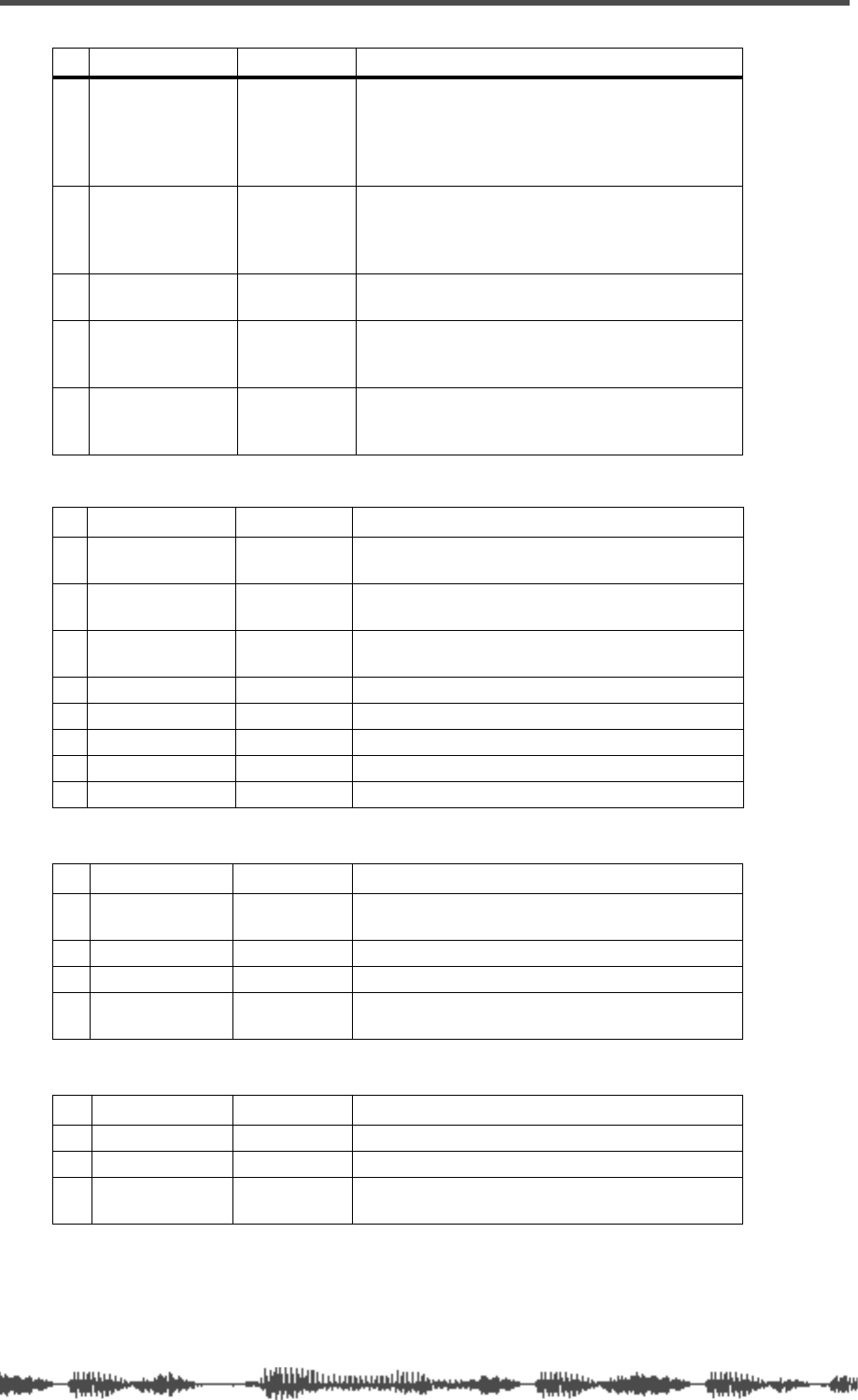
Effects
126
VM200 User’s Guide
Early Reflection-type Reverbs
Delays
Modulation effects
20 Presence Vocal
Booth PVo.BOOTH
The early reflections of an ideal vocal booth plus
short reverberation with extended high range. This
adds sparkle to the sound, and is effective when
you want to make the vocal stand out in the
ensemble.
21 Natural Vocal
Booth NVo.BOOTH
The early reflections of an ideal vocal booth plus
gentle short reverberation. This adds a natural
feeling of air, and is effective with simple arrange-
ments with an unhurried vocal.
22 Vocal Reverb Vo.REVERB All-around reverb that makes any vocal sound
great.
23 Solo Vocal Solo.VO Spacious short delay plus a reverb with a real
plate character. Blends naturally into any back-
ground.
24 Arena Vocal Arena VO Spacious stadium-type early reflections plus short
reverberation with extended high range. Good for
chorus parts.
# Name Display Description
25 Normal Gate
Reverb Nom.GATE Standard gate reverb
26 Lo-Freq Mono
Kick Gate MnBD.GATE Gate reverb tuned for kick drums, with pan set to
the center.
27 Hi-Freq Stereo
Snare Gate StSD.GATE Gate reverb tuned for snare drums and percussion
28 Hall E/R Hall.ER Simulation of early reflections in a large hall.
29 Room E/R Room.ER Simulation of early reflections in a room.
30 Spring E/R Spring.ER Simulation of early reflections of a spring reverb.
31 Random E/R Random.ER Random early reflections.
32 Reverse E/R Reverse.ER Reversed early reflections of a hall reverb.
# Name Display Description
33 Mono Delay MonoDELAY Mono delay with longer delay time, which can cre-
ate special effects using HPF and LPF.
34 Pan Delay Pan.DELAY Panning delay that pans sound left to right.
35 Dual Delay DualDELAY Two independent delays.
36 3ch Delay 3ch.DELAY 3-tap delay, which can create interesting effects
with your wizardry.
# Name Display Description
37 Chorus CHORUS Standard chorus effect setting.
38 3D Chorus 3D.CHORUS More natural and spacious effects than Chorus.
39 Flange FLANGE Standard flanging effect setting. You can pan two
types of effects sound to any position.
# Name Display Description
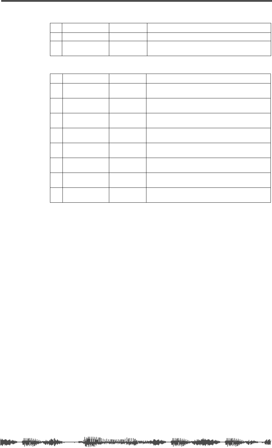
Effect Preset Library List
VM200 User’s Guide
127
Pitch Changer
Multi-effects
# Name Display Description
40 Mono PitCh MonoPITCH Standard pitch shifter.
41 Dual PitCh DualPITCH Stereo pitch shift with two channels pitch-shifted
independently.
# Name Display Description
42 Mono Delay
-Normal Hall MnDL-NmHL Combination of mono delay and hall reverb.
43 Mono Delay
-Normal Plate MnDL-NmPL Combination of mono delay and plate reverb.
44 Panning Delay
-Normal Hall PnDL-NmHL Combination of pan delay and hall reverb.
45 Panning Delay
-Normal Plate PnDL-NmPL Combination of pan delay and plate reverb.
46 CHORUS-
REVERB CHORS-REV An effect which adds reverb to chorus.
47 REVERB-
CHORUS REV-CHORS An effect which adds chorus to reverb.
48 FLANGE-
REVERB FLG-REV An effect which adds reverb to flange.
49 REVERB
-FLANGE REV-FLG An effect which adds flange to reverb.
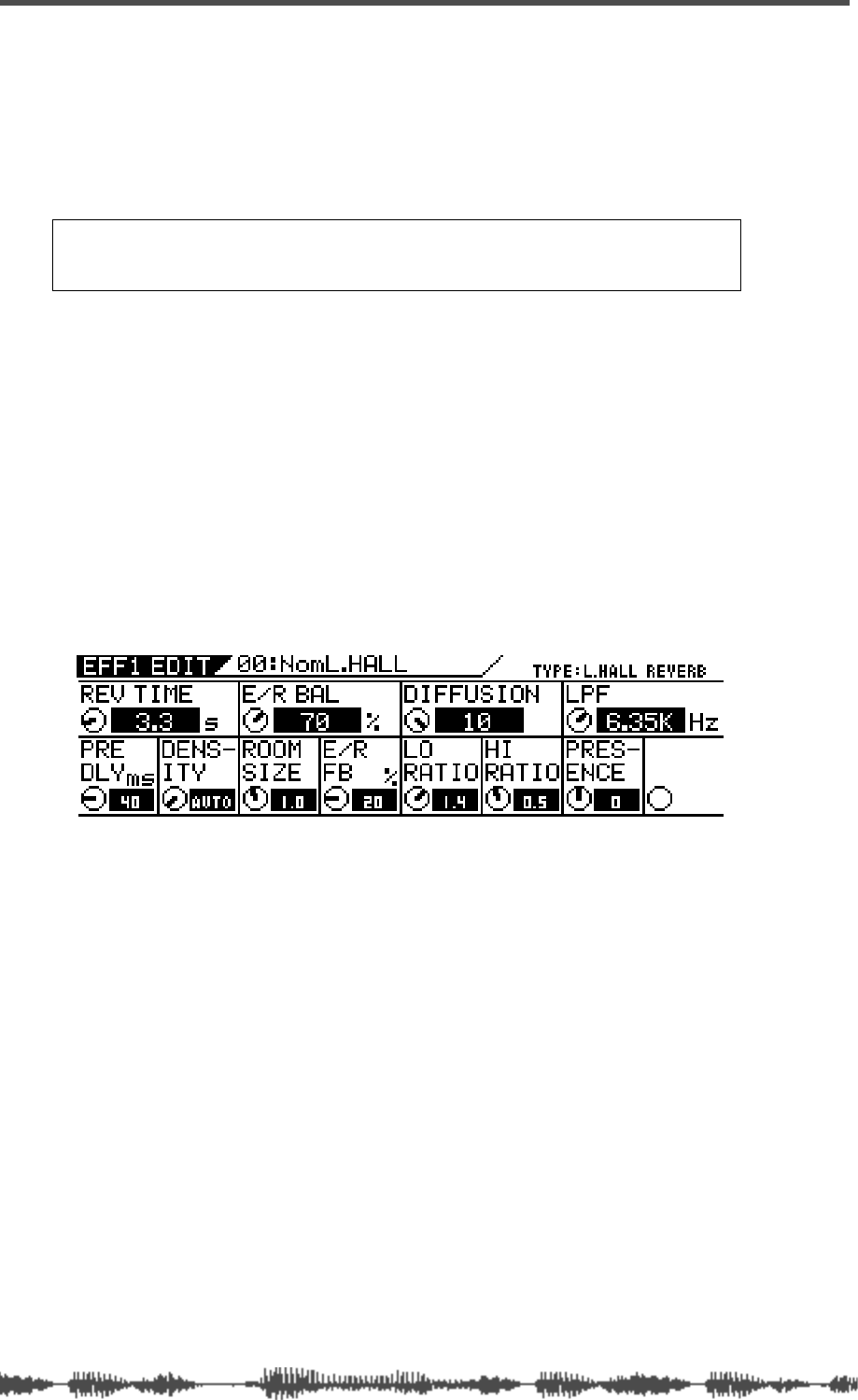
Effects
128
VM200 User’s Guide
Applying Effects
To apply an effect, you must do two things:
❑
route the signal to one of two effects processors, and
❑
return the processed signal back to the mix.
The following sections explain these tasks.
Selecting an Effects Processor
1.
Press the
[CHANNEL/METER
] key.
The VM200 displays the
CHANNEL EDIT
function page.
2.
Check the input channel, turn on the
[ON]
key, and raise the
fader for the channel.
3.
Press the
[EFF1]
or
[EFF2]
key in the Eff Edit section to select
an effects processor.
The selected key lights up and the VM200 displays the
EFF EDIT
function page, which includes parameters for the current effect.
4.
Recall the desired effects program from the Effects Library.
(For more information on how to recall the effects program, see
“Recalling Effects Programs” on page 134.)
Setting Effects Return
Before you send a signal to an effects processor, you must set up a
routing path to return it to the mix so it can be monitored and output.
Follow the steps below:
5.
Press the
[CHANNEL/METER]
key, then the
[17–20 EFF RTN]
key.
The
[17–20 EFF RTN]
key lights up.
Note:
When EQ Enable parameter is set to “EQ1–16,” both effects proces-
sors are disabled. For more information, see “EQ Enabling Channels” on
page 80.

Sending Signal to Effects Processor
VM200 User’s Guide
129
6.
Lower then raise the faders that correspond to the effect you
are using for return signals. Make sure the corresponding
channel
[ON]
key is turned on.
(Channels 17 & 18 faders control the EFF1 processor; channels
19 & 20 faders control EFF2.)
You must lower then raise the fader to set the initial return level.
(See “Faders” on page 32 for more information.)
7.
Adjust the PAN control for the effects return channel if you
desire.
Sending Signal to Effects Processor
8.
Press the
[1–8 ANALOG IN]
Page Select key.
The
[17–20 EFF RTN]
key LED turns off and the
[1–8 ANALOG IN]
Page Select key lights up.
9.
Press the
[EFF1]
key in the Fader Mode section. (If you are
using the EFF2 processor, press the
[EFF2]
key.)
The
[EFF1]
key flashes orange and the
[AUX1]
key flashes red in the
Fader Mode section.
10.
Lower then raise the fader for the channel you wish to route
to the effects processor. Then lower and raise the Master fader
to set the desired effects send signal level.
This sends the channel signal to the selected effects processor.
The effects send meter in the
CH VIEW
function page displays the
level of the effects send signal, indicating that signals are being fed
to the selected effects processor. As you raise the faders, you
should hear more of the effect sound.
If input channels are paired, their effect send controls will be
linked.
You can edit and store effects settings. Refer to “Storing Effects
Programs” on page 135 for more information.
Routing Effects Returns
Once you’ve routed a signal to an effects processor and returned it to
the mix as described in the preceding sections, you can route it to sev-
eral destinations.
You can route Effects returns to the stereo buss (ST BUSS) or the
recording buss (REC BUSS). See “Routing Input Channels” on
page 66 for more information.
You can also route signals to AUX Sends 1 through 4. (Note that the
REC BUSS OUT is disabled if AUX Sends 3 and 4 are selected).
Note:
If you set the Smoothing function to Level 2 (default), AUX1 and
EFF1 are linked, and AUX2 and EFF2 are linked. Therefore, setting the
EFF1 level will set AUX1 to the same level. Similarly, setting the EFF2 level
sets AUX2 to the same level. If the Smoothing function is set to Level 1, you
may hear a slight stepping noise when you move the fader. For more infor-
mation, see “Smoothing Function” on page 120.
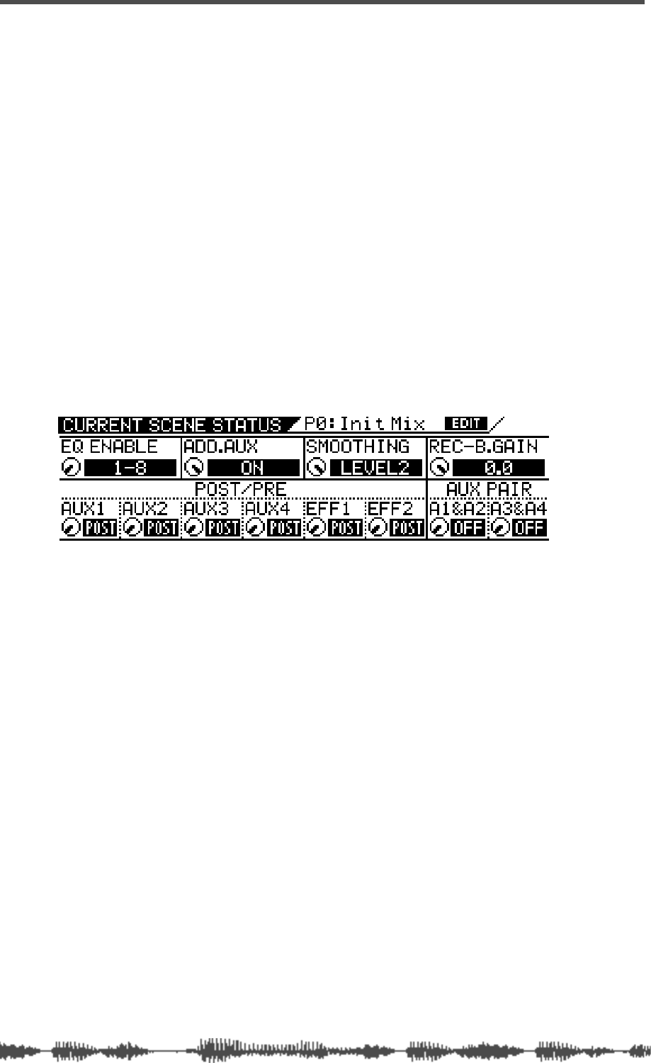
Effects
130
VM200 User’s Guide
Controlling the Sends Signals
Pre-fader/Post-fader Effect Sends
You can configure each Effect Send on input channels 1 through 20
as “pre-fader” or “post-fader” by adjusting parameters on the
CURRENT
SCENE STATUS
function page.
Pre-fader signals do not pass through the channel faders and are
therefore unaffected by channel fader settings. Post-fader signals
pass through the channel faders and are affected by channel fader
settings.
The channel faders enable you to adjust the channel level and the
Effect Send level of post-fader signals simultaneously.
Follow the steps below to select “pre-fader” or “post-fader” for an
effect processor.
1.
Press the
[CURRENT SCENE STATUS]
key.
The VM200 displays the
CURRENT SCENE STATUS
function page:
2.
Rotate the Freq and Q rotary controls for channels 5–6 to
select PRE or POST for the EFF1 and EFF2 parameters.
The default setting is “POST.”
When you change the setting, the selected value flashes.
3.
Press the
[ENTER]
key to confirm the selection.
4.
Press the
[EXIT]
key to display the
CHANNEL EDIT
function page.
Viewing and Adjusting the Effect Send Level
The VM200 enables you to view and adjust effect send levels for
effects processors EFF1 and EFF2 on the Channel View (
CH VIEW
)
function page. A graphic image of a fader and a numerical value rep-
resent the send levels on the display.
To view and adjust the effect send levels, follow these steps:
1.
Press the
[CH VIEW]
key.
The
[CH VIEW]
key and all
[EQ EDIT]
keys flash.
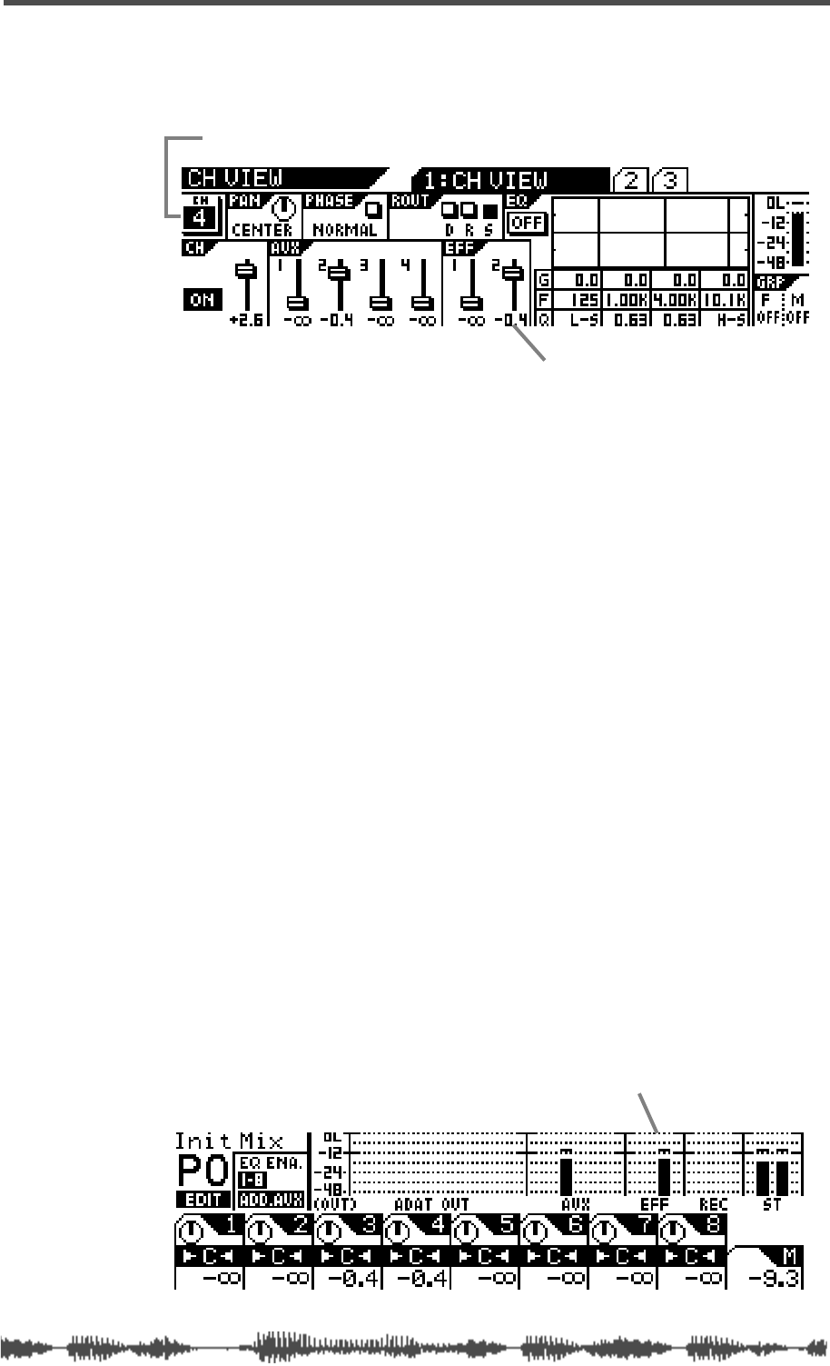
Viewing and Adjusting the Effect Send Master Level
VM200 User’s Guide
131
The VM200 displays the
1:CH VIEW
function page, which includes
graphic and numeric indicators of the effect send levels for EFF1
and EFF2.
2.
If you wish to adjust the effect send level, specify a channel
whose fader you wish to use by pressing a Page Select key and
the
[EQ EDIT]
key for the channel.
The VM200 displays a new channel number in the CH section,
near the upper-left corner of the display.
3.
Press the EFF1 or EFF2 key in the Fader Mode section to
specify an effects processor.
The selected key flashes.
4.
Raise the fader for the corresponding channel.
The graphic fader and numerical read-out on the display reflect
the adjustment in real-time.
Viewing and Adjusting the Effect Send Master Level
You can control Effect Send master levels using the Master fader in
the appropriate Fader Mode.
1.
Press the
[EFF1]
or
[EFF2]
key in the Fader Mode section to
specify the effects processor you wish to adjust.
The selected key flashes.
2.
Raise or lower the Master fader to adjust the Effect Send mas-
ter level.
The Effect Sends master level is displayed on the output channel
page of the
CHANNEL EDIT
function page (also called the “
CHANNEL
EDIT/OUTPUT
” function page).
effect send fader level
channel number
effect send master level

Effects
132
VM200 UserÕs Guide
Muting Effect Sends
You can mute Effect Send masters using the Master
[ON]
key. The
function of this key depends on the selected Fader mode. See “[ON]
Keys” on page 34 for more information.
1.
Press the
[EFF1]
or
[EFF2]
key in the Fader Mode section to
select Effect Send 1 or 2.
2.
Press the Master
[ON]
key to turn the Effect Send on or off.
Monitoring Effects Sends
You can monitor the EFF send signal by connecting the MONITOR
OUT jacks to an amplifier and speakers. Set the Mon Sel (Monitor
Select) parameter on the
SETUP:SYSTEM 1: CLOCK/MON
function page to
EFF1 or EFF2.
You can also monitor the EFF send signal through a pair of stereo
headphones connected to the PHONES jack. For more information,
see “Monitoring Signals” on page 97.
Controlling the Return Signals
This section explains how to set levels and pan effect return.
Setting the Effect Return Level
You can use the channels 17–20 faders to adjust the Effect return level.
1.
Press the
[CHANNEL]
key in the Fader Mode section.
2.
Press the
[17–20 EFF RTN]
Page Select key.
3.
Raise the channel fader to adjust the level.
You can view the effect return level on the
CHANNEL EDIT/INPUT
func-
tion page.
Panning Effects Returns
The Channels 17–20 panpots pan signals between the left and right
channels of the Stereo Buss Out and Rec Buss Out, and the odd and
even AUX buss outs. See “Panning Input Channels” on page 65 for
more information.
effect return level

Effects Library
VM200 User’s Guide
133
Effects Library
The VM200 stores effects settings as programs in the Effects Library,
which contains 50 Preset programs (0–49) and 50 User programs
(50–99).
The Preset effects programs are designed for specific applications and
instruments, and include numerous reverbs, delays, choruses,
flangers, and combinations. See “Effect Preset Library List” on
page 125 for a table of Preset effects programs.
You can customize the Preset programs, assign each one a name, and
store them as User programs.
You can load effects from the Effects Library to either effects proces-
sor (EFF1 or EFF2).
Editing Effects
You can edit effects programs and then store them as user programs
in program numbers 50–99.
1. Recall the effect you wish to edit to the EFF1 or EFF2 proces-
sor.
See “Recalling Effects Programs” on page 134 for more informa-
tion on recalling effects.
2. Press the corresponding [EFF1] or [EFF2] key in the Eff Edit
section.
(If you recalled the effect to EFF1 in step 1, press the [EFF1] key in
this step, etc.)
The VM200 displays the EFF EDIT function page for the selected
effect, and the selected key lights up.
3. Use the Gain, Freq, and Q rotary controls to adjust the value
of each parameter.
If you wish to store the change, refer to “Storing Effects Programs”
on page 135.
4. Press the [EXIT] key to return to Channel Edit mode.
All parameters are described in detail in “Effects Parameters” on
page 139.
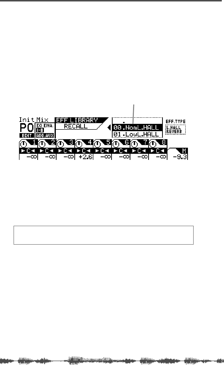
Effects
134 VM200 User’s Guide
Recalling Effects Programs
You can recall Effects programs 0 through 99.
1. Press the [EFF1] or [EFF2] key in the Eff Edit section to specify
the effects processor to which you want to recall the effect.
The VM200 displays the function page for the effect currently
loaded to the effects processor. The [EFF1] or [EFF2] key you
selected lights up.
2. Press the [RECALL] key in the Eff Library section.
The VM200 displays the EFF LIBRARY RECALL function page, and the
[EFF1] or [EFF2] key flashes.
3. Use the Data Wheel or the [</-1] and [+1/>] keys to select the
desired effect program number from the program listing on
the function page.
4. Press the [ENTER] key.
The VM200 recalls the effect program to the specified effects pro-
cessor and displays the selected effect’s parameter function page.
5. You can press the [EXIT] key to return to Channel Edit mode
at any time.
Note: If an effect program in the library contains no data, the term
“NO_DATA” will appear on the display. You cannot recall such programs
until you store effect data in the program.
scroll list
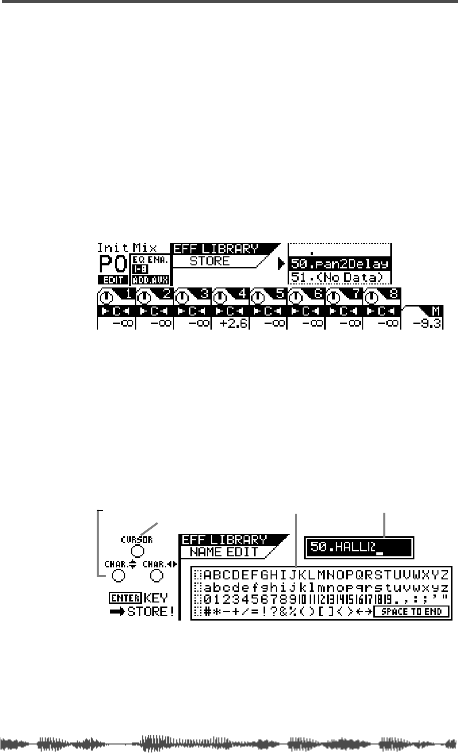
Storing Effects Programs
VM200 User’s Guide 135
Storing Effects Programs
You can store effect settings in User programs 50 through 99.
1. Press the [EFF1] or [EFF2] key in the Eff Edit section to specify
the effects processor to which you want to store the effect.
The VM200 displays the function page for the effect currently
loaded to the effects processor, and the [EFF1] or [EFF2] key you
selected lights up.
You can modify any Preset program or previously-stored User pro-
gram. Make any adjustments you like, then continue with this
procedure to store the “new” effect.
2. Press the [STORE] key in the Eff Library section.
The VM200 displays the EFF LIBRARY STORE function page, and the
[EFF1] or [EFF2] key flashes.
3. Rotate the Data Wheel or the [</-1] and [+1/>] keys to select an
Effect program location.
The effect program numbers and names scroll in the upper-right
of the display. You can select program numbers 50 to 99, inclu-
sive. Effect programs that contain no data are labeled “(No Data)”.
4. Press the [ENTER] key.
The VM200 displays the EFF LIBRARY NAME EDIT function page, which
enables you to name or re-name effect programs. The program
title appears in the upper-right of the display.
The EFF LIBRARY NAME EDIT function page includes a character set
box that displays all the letters of the alphabet, as well as numer-
als and punctuation symbols. You can use these characters to
name or title your effect program.
You can use any triangle of Gain, Freq, and Q rotary controls to
select the characters for the title.
character-selector title boxcharacter set box
cursor
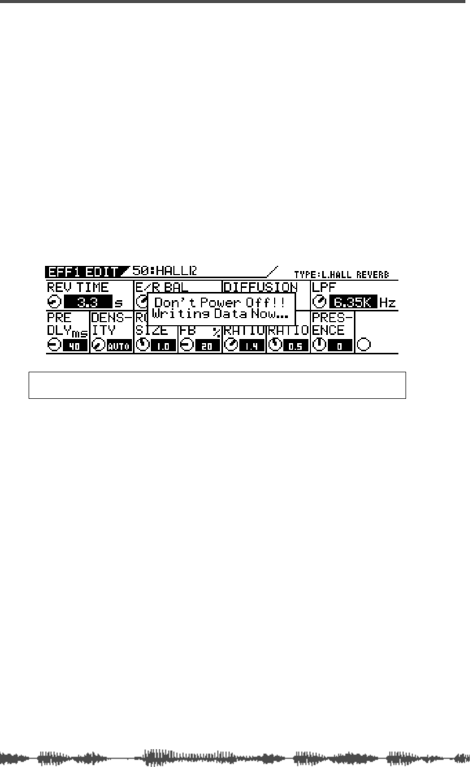
Effects
136 VM200 User’s Guide
The Gain control moves the cursor position left and right in the
title box. The Freq control moves the character-selector up and
down the matrix; the Q control moves the character-selector left
and right.
You can also press the [</-1] and [+1/>] keys to move the cursor
and rotate the Data Wheel to select characters or numbers.
5. Rotate the Freq and Q rotary controls to select a character,
then turn the Gain rotary control one notch right to move
the cursor to the next space in the name, and repeat the pro-
cess.
The very useful “Space to End” option in the lower-right corner of
the character set box will fill-in the remainder of your title with
blank spaces.
6. When you’ve finished naming the program, press the [ENTER]
key to store the Effect program.
The following warning dialog appears for a brief moment.
After the warning, the VM200 displays the EFF EDIT function page.
7. Press the [EXIT] key any time to exit the EFF LIBRARY STORE or
EFF LIBRARY NAME EDIT function pages.
The VM200 displays the CHANNEL EDIT function page.
Warning: Do not power off the VM200 while it is writing to the flash
memory or you may damage the VM200.
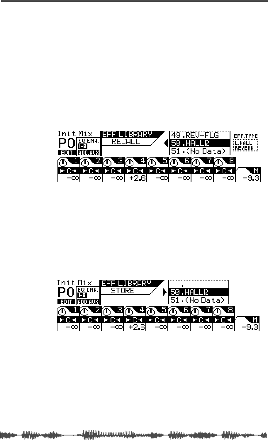
Editing Effect Program Titles
VM200 User’s Guide 137
Editing Effect Program Titles
You can edit Effect program titles, just in case you want to change
their name for some reason. To do so, you recall the target Effect pro-
gram to a channel, then re-store it with a different title.
1. Press the [EFF1] or [EFF2] key in the Eff Edit section to specify
the effects processor to which you want to recall the effect.
The VM200 displays the function page for the effect currently
loaded to the effects processor, and the [EFF1] or [EFF2] key you
selected lights up.
2. Press the [RECALL] key in the Eff Library section.
The VM200 displays the EFF LIBRARY RECALL function page, and the
[EFF1] or [EFF2] key flashes.
3. Rotate the Data Wheel or use the [</-1] and [+1/>] keys to
select an Effect program you wish to rename.
You cannot change the title of Preset programs 00–49.
4. Press the [ENTER] key to recall the desired Effect program.
The VM200 recalls the effect program to the specified effects pro-
cessor and displays the selected effect’s parameter function page.
5. Press the [STORE] key in the Eff Library section.
The VM200 displays the EFF LIBRARY STORE function page, and the
[EFF1] or [EFF2] key flashes.
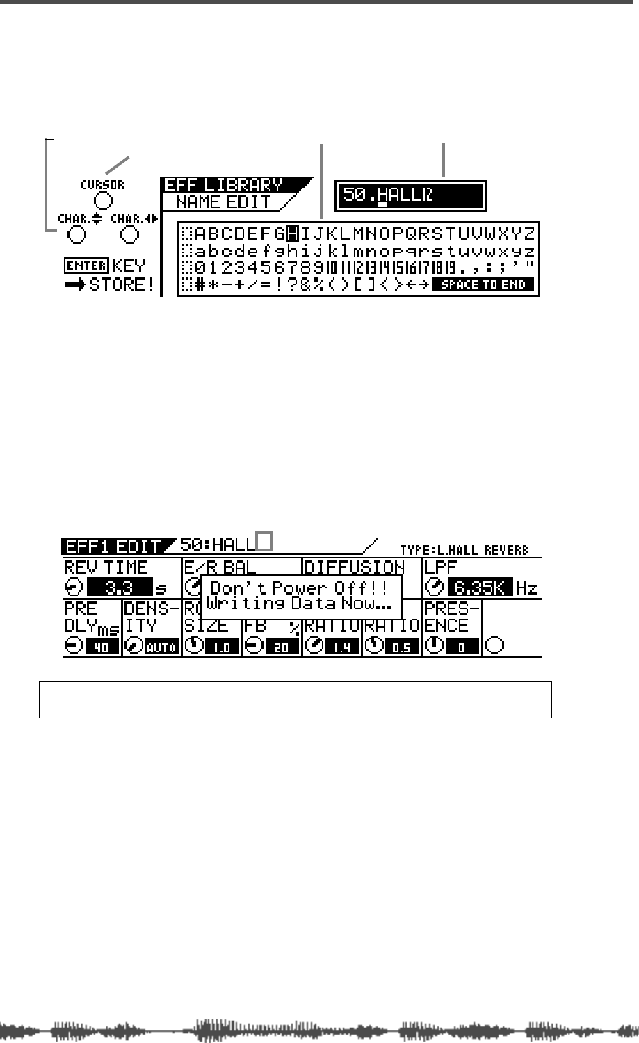
Effects
138 VM200 User’s Guide
6. Press the [ENTER] key.
The VM200 displays the EFF LIBRARY NAME EDIT function page. The
title box shows the program number and the current name.
Use any Gain, Freq, and Q rotary controls to re-assign a name to
the Effect program.
You can also press the [</-1] and [+1/>] keys to move the cursor
and rotate the Data Wheel to select characters or numbers.
Refer to step 4 of “Storing Effects Programs” on page 135 for
information on assigning a name.
7. When you’ve finished re-naming the program, press the
[ENTER] key to store the new Effect program title.
The following warning dialog appears for a brief moment.
After the warning, the VM200 displays the EFF EDIT function page.
8. Press the [EXIT] key any time to exit the EFF LIBRARY STORE or EQ
LIBRARY NAME EDIT function pages.
The VM200 displays the CHANNEL EDIT function page.
Warning: Do not power off the VM200 while it is writing to the flash
memory or you may damage the VM200.
character-selector title boxcharacter set box
cursor
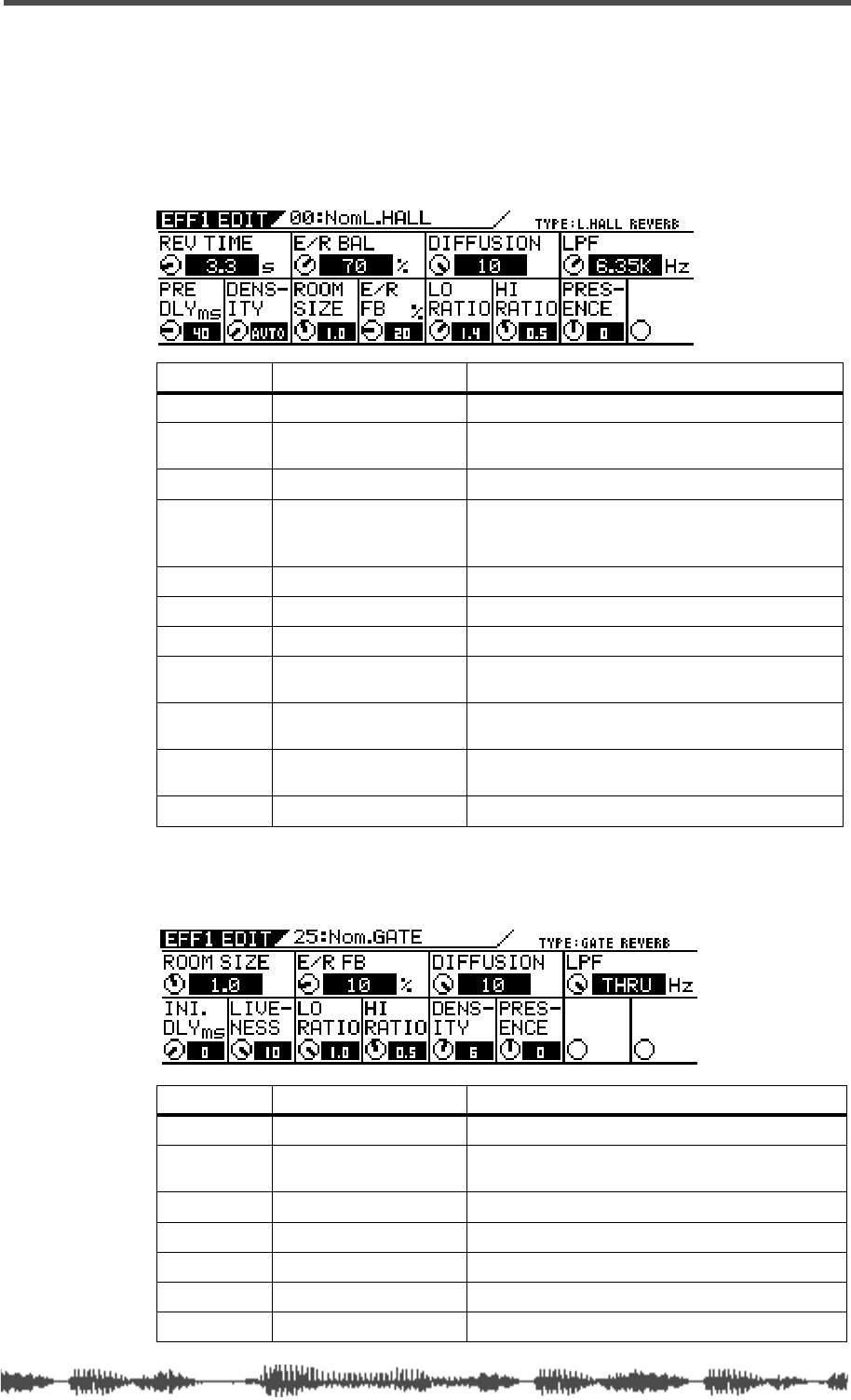
Effects Parameters
VM200 User’s Guide 139
Effects Parameters
The following tables list the parameters of each effect type. The num-
bers in parentheses indicate the preset effects that belong to the
effect types.
Reverb-type Effects (00–24)
Early Reflection-type Effects (25–32)
Parameter Value Description
REV TIME 0.1–30.0 [s] (0.1 step) Length of the reverberation.
PRE DLY 0–160 [ms] (1 step) Delay time from the early reflections until the
reverb.
DENSITY 0–10, AUTO 1
1. With AUTO, the optimum value for the REV TIME setting will be used.
Density of the reverb.
E/R BAL 0–100 [%] (1 step) Volume balance between the early reflections
and the reverb. Only ER with 0%, and only reverb
with 100%.
ROOM SIZE 0.1–2.0 (0.1 step) The size of the room (relative to E/R).
E/R FB 0–100 [%] (1 step) Degree of repeated early reflections
DIFFUSION 0–10 (1 step) Left/right spread of the reverb effects.
LO RATIO 0.1–2.0 (0.1 step) Length of the low frequency reverberation,
expressed as a ratio relative to the REV.TIME.
HI RATIO 0.1–2.0 (0.1 step) Length of the high frequency reverberation,
expressed as a ratio relative to REV.TIME.
LPF 1.00kHz–20.2kHz, THRU
(step: same as EQ) Cut-off frequency of the low pass filter.
PRESENCE -10–0–+10 (1 step)2
2. Brightness increases with a positive setting, and decreases with a negative setting.
Brightness in the high range of the reverb.
Parameter Value Description
ROOM SIZE 0.1–2.0 (0.1 step) The size of the room (relative to E/R).
INI.DLY 0–200 [ms] (1 step)
TBD Delay time from the dry sound until the early
reflections of the reverb are heard.
LIVENESS 0–10 (1 step)1Adjusts how the reflections decay.
E/R FB 0–100 [%] (1 step) Degree of repeated early reflections
LO RATIO 0.1–1.0 (0.1 step) Low frequency amount of the feedback.
HI RATIO 0.1–1.0 (0.1 step) Low frequency amount of the feedback.
DIFFUSION 0–10 (1 step) Left/right spread of the reflections.
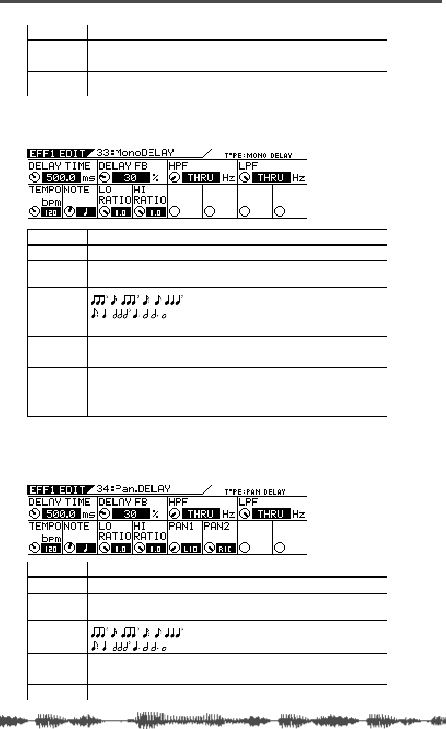
Effects
140 VM200 User’s Guide
MONO_DELAY (33)
PAN_DELAY (34)
DENSITY 0–10 (1 step) Density of the reverb.
PRESENCE -10–0–+10 (1 step)2Brightness in the high range of the reverb.
LPF 1.00kHz–20.2kHz, THRU
(step: same as EQ) Cut-off frequency of the low pass filter.
1. 0: dead, 10: live
2. Brightness increases with a positive setting, and decreases with a negative setting.
Parameter Value Description
DELAY TIME 0.1–1360.0 [ms] (0.1 step) Delay time. 1
1. If you adjust DELAY TIME, NOTE will be automatically changed.
TEMPO 30–250 [bps] (1 step) Tempo value used to calculate DELAY TIME and
NOTE.2
2. If you adjust TEMPO, DELAY TIME will be automatically changed.
NOTE Note value used to calculate DELAY TIME.3
3. If you adjust NOTE, DELAY TIME will be automatically changed.
DELAY FB 0–100 [%] (1 step) Amount of delay feedback.
LO RATIO 0.1–1.0 (0.1 step) Low frequency amount of the feedback.
HI RATIO 0.1–1.0 (0.1 step) High frequency amount of the feedback.
HPF THRU, Same as EQ
value [Hz] Cut-off frequency of the high pass filter.
LPF Same as EQ value [Hz],
THRU Cut-off frequency of the low pass filter.
Parameter Value Description
DELAY TIME 0.1–1360.0 [ms] (0.1 step) Delay time. 1
TEMPO 30–250 [bps] (1 step) Tempo value used to calculate DELAY TIME and
NOTE.2
NOTE Note value used to calculate DELAY TIME.3
DELAY FB 0–100 [%] (1 step) Amount of delay feedback.
LO RATIO 0.1–1.0 (0.1 step) Low frequency amount of the feedback.
HI RATIO 0.1–1.0 (0.1 step) High frequency amount of the feedback.
Parameter Value Description
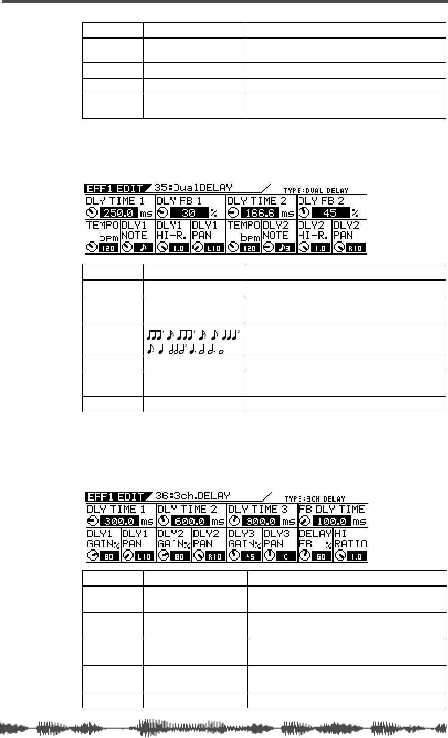
Effects Parameters
VM200 User’s Guide 141
DUAL_DELAY (35)
3CH_DELAY (36)
HPF THRU, Same as EQ
value [Hz] Cut-off frequency of the high pass filter.
PAN1 L10.0–0.0–R100 (0.5 step) Pan position of the first delay.
PAN2 L10.0–0.0–R100 (0.5 step) Pan position of the second delay.
LPF Same as EQ value [Hz],
THRU Cut-off frequency of the low pass filter.
1. If you adjust DELAY TIME, NOTE will be automatically changed.
2. If you adjust TEMPO, DELAY TIME will be automatically changed.
3. If you adjust NOTE, DELAY TIME will be automatically changed.
Parameter Value Description
DLY TIME1/2 0.0–680.0 [ms] (0.1 step) Delay time of DELAY 1 or 2.1
1. If you change DELAY TIME, NOTE will be automatically changed.
TEMPO 30–250 [bps] (1 step) Tempo value used to calculate DLY TIME1, DLY
TIME2, NOTE1, and NOTE2. 2
2. If you change TEMPO, DELAY TIME will be automatically changed. Two TEMPO
parameter rotary controls operate in sync.
DLY1/2NOTE Note value used to calculate DLY TIME1 or 2.3
3. If you change DELAY TIME or TEMPO, the closest note value will be selected.
DLY FB1/2 0–100 [%] (1 step) Amount of DELAY1 or 2 feedback.
DLY1/2HI-R. 0.1–1.0 (0.1 step) High frequency amount of the DELAY 1 or 2 feed-
back.
DLY1/2PAN L10.0–0.0–R10.0 (0.5 step) Pan position of the DELAY 1 or 2.
Parameter Value Description
DLY TIME
1/2/3 0.1–1360.0 [ms] (0.1 step) Delay time. (0.1 step when ENTER is pressed.)
DLY1/2/3
GAIN 0–100 [%] (1 step) Delay 1/2/3 level.
DLY1/2/3
PAN L10.0–0.0–R10.0 (0.5 step) Delay 1/2/3 pan position.
FB DLY
TIME 0.1–1360.0 [ms] (0.1 step) Delay time of feedback
DELAY FB 0–100 [%] (1 step) Amount of delay feedback.
Parameter Value Description
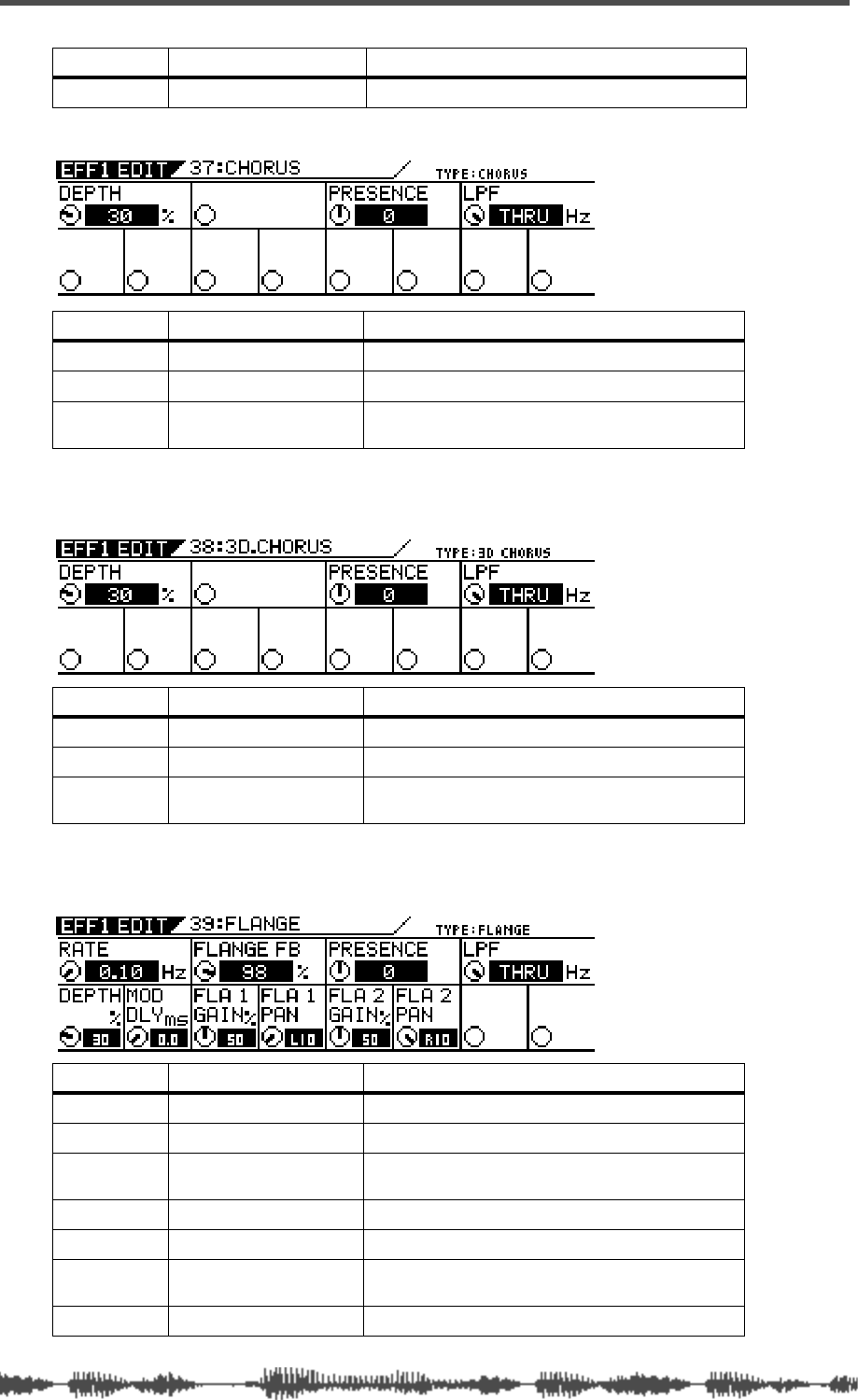
Effects
142 VM200 User’s Guide
CHORUS (37)
3D_CHORUS (38)
FLANGE (39)
HI RATIO 0.1–1.0 (0.1 step) High frequency amount of the feedback.
Parameter Value Description
DEPTH 0–100 [%] (1 step) Modulation depth
PRESENCE -10–0–+10 (1 step)1
1. Brightness increases with a positive setting, and decreases with a negative setting.
Brightness in the high range of the reverb.
LPF 1.00kHz–20.2kHz, THRU
(step: same as EQ) Cut-off frequency of the low pass filter.
Parameter Value Description
DEPTH 0–100 [%] (1 step) Modulation depth.
PRESENCE -10–0–+10 (1 step)1
1. Brightness increases with a positive setting, and decreases with a negative setting.
Brightness in the high range of the reverb.
LPF 1.00kHz–20.2kHz, THRU
(step: same as EQ) Cut-off frequency of the low pass filter.
Parameter Value Description
RATE 0.01–2.00 [Hz] (0.01 step) Modulation speed.
DEPTH 0–100 [%] (1 step) Modulation depth.
MOD DLY 0.0–30.0 [ms] (0.1 step) Delay time from the direct sound until the modu-
lated sound.
FLANGE FB 0–100 [%] (1 step) Feedback amount.
FLA1/2GAIN 0–100 [%] (1 step) Gain of FLANGE 1 or 2.
FLA1/2PAN L10.00–0.0–R10.0 (0.5
step) Pan position of FLANGE 1 or 2.
PRESENCE -10–0–+10 (1 step)1Brightness in the high range of the reverberation.
Parameter Value Description
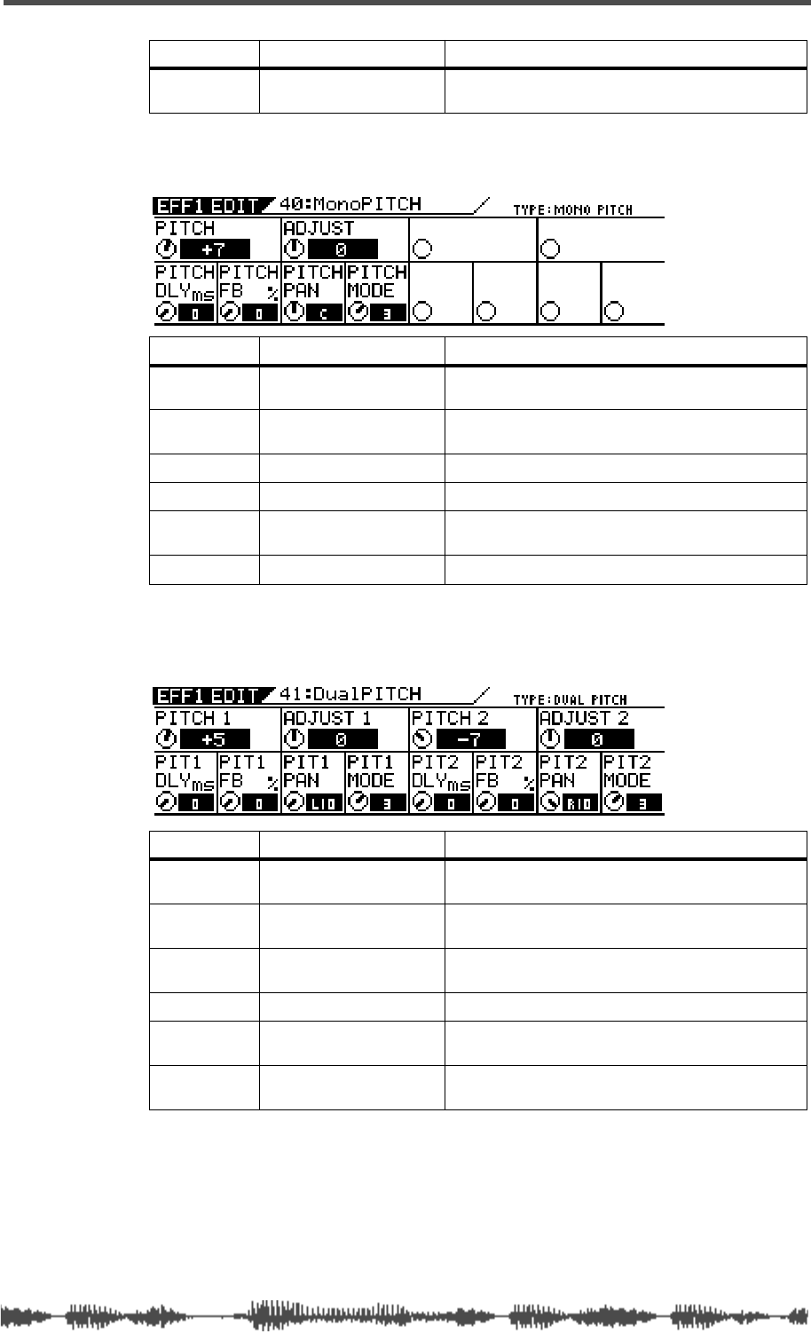
Effects Parameters
VM200 User’s Guide 143
MONO_PITCH (40)
DUAL_PITCH (41)
LPF 1.00kHz–20.2kHz, THRU
(step: same as EQ) Cut-off frequency of the low pass filter.
1. Brightness increases with a positive setting, and decreases with a negative setting.
Parameter Value Description
PITCH -24–0–+24 (1 step)
(+/-2 octave) Amount of pitch shift.
ADJUST -100–0–+100 (1 step)
(+/- semitone) Fine adjustment to the pitch shift.
PITCH DLY 0–340 [ms] (1 step) Delay time of the pitch shift.
PITCH FB 0–100 [%] (1 step) Feedback amount.
PITCH PAN L10.0–0.0–R10.0 (0.5
step) Pan position of the pitch shift.
PITCH MODE 1, 2, 3, 4 1
1. Select “1” when response speed is priority. Select “2” for a typical setting. Select “3” or
“4” for more clarity.
Selects the size of the buffer for pitch shift.
Parameter Value Description
PITCH1/2 -24–0–+24 (1 step)
(+/-2 octave) Amount of pitch shift for PITCH SHIFT 1 or 2.
ADJUST1/2 -100–0–+100 (1 step)
(+/- semitone) Fine adjustment to the pitch shift for PITCH
SHIFT 1 or 2.
PIT1/2 DLY 0–340 [ms] (1 step) Delay time of the pitch shift for PITCH SHIFT 1 or
2.
PIT1/2 FB 0–100 [%] (1 step) Feedback amount for PITCH SHIFT 1 or 2.
PIT1/2 PAN L10.0–0.0–R10.0 (0.5
step) Pan position of PITCH SHIFT 1 or 2.
PIT1/2 MODE 1, 2, 3, 4 1
1. Select “1” when response speed is priority. Select “2” for a typical setting. Select “3” or
“4” for more clarity.
Selects the size of the buffer for PITCH SHIFT 1
or 2.
Parameter Value Description
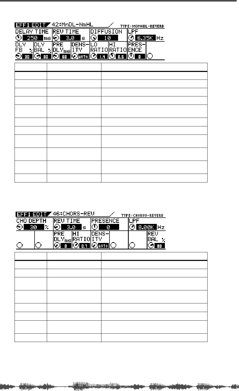
Effects
144 VM200 User’s Guide
Delay->Reverb-type Effects (42–45)
CHORUS-REVERB (46)
Parameter Value Description
DELAY TIME 1–500 [ms] (1 step) Delay time.
DELAY FB 0–100 [%] (1 step) Amount of delay feedback.
DELAY BAL 0–100 [%] (1 step) Delay sound level.
REV TIME 0.1–30.0 [s] (0.1 step) Length of the reverberation.
PRE DLY 0–160 [ms] (1 step) Delay time from the early reflections until the
reverb.
DENSITY 0–10, AUTO 1
1. With AUTO, the optimum value for the REV TIME setting will be used.
Density of the reverb.
DIFFUSION 0–100 [%] (1 step) Left/right spread of the reverb effects.
LO RATIO 0.1–2.0 (0.1 step) Length of the low frequency reverberation,
expressed as a ratio relative to the REV.TIME.
HI RATIO 0.1–1.0 (0.1 step) Length of the high frequency reverberation,
expressed as a ratio relative to REV.TIME.
LPF 1.00kHz–20.2kHz, THRU
(step: same as EQ) Cut-off frequency of the low pass filter.
PRESENCE -10–0–+10 (1 step)2
2. Brightness increases with a positive setting, and decreases with a negative setting.
Brightness in the high range of the reverb.
Parameter Value Description
CHO DEPTH 0–100 [%] (1 step) Modulation depth.
REV TIME 0.1–30.0 [s] (0.1 step) Length of the reverberation.
PRE DLY 0–160 [ms] (1 step) Delay time from the early reflections until the
reverb.
HI RATIO 0.1–1.0 (0.1 step) Length of the high frequency reverberation,
expressed as a ratio relative to REV.TIME.
PRESENCE -10–0–+10 (1 step)1
1. Brightness increases with a positive setting, and decreases with a negative setting.
Brightness in the high range of the reverb.
DENSITY 0–10, AUTO 2
2. With AUTO, the optimum value for the REV TIME setting will be used.
Density of the reverb.
LPF 1.00kHz–20.2kHz, THRU
(step: same as EQ) Cut-off frequency of the low pass filter.
REV BAL 0–100 [%] (1 step) Level of reverb sound.
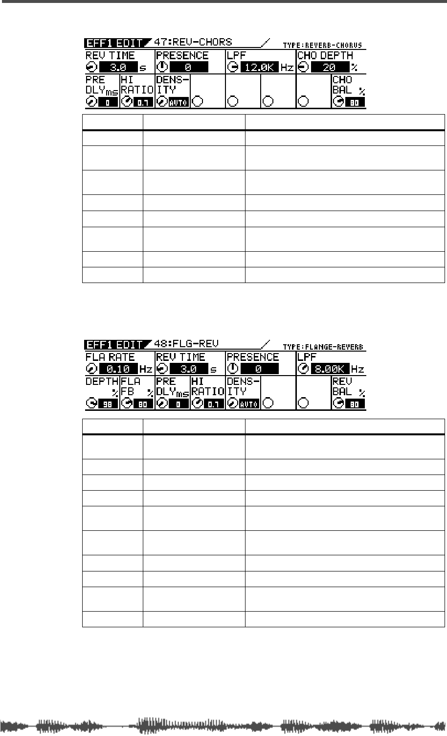
Effects Parameters
VM200 User’s Guide 145
REVERB-CHORUS (47)
FLANGE-REVERB (48)
Parameter Value Description
REV TIME 0.1–30.0 [s] (0.1 step) Length of the reverberation.
PRE DLY 0–160 [ms] (1 step) Delay time from the early reflections until the
reverb.
HI RATIO 0.1–1.0 (0.1 step) Length of the high frequency reverberation,
expressed as a ratio relative to REV.TIME.
PRESENCE -10–0–+10 (1 step)1
1. Brightness increases with a positive setting, and decreases with a negative setting.
Brightness in the high range of the reverb.
DENSITY 0–10, AUTO 2
2. With AUTO, the optimum value for the REV TIME setting will be used.
Density of the reverb.
LPF 1.00kHz–20.2kHz, THRU
(step: same as EQ) Cut-off frequency of the low pass filter.
CHO DEPTH 0–100 [%] (1 step) Modulation depth.
CHO BAL 0–100 [%] (1 step) Level of chorus sound.
Parameter Value Description
FLA RATE 0.01–2.00 [Hz] (00.1 step) Modulation speed. (0.01 step when ENTER is
pressed.)
DEPTH 0–100 [%] (1 step) Modulation depth.
FLA FB 0–100 [%] (1 step) Feedback amount.
REV TIME 0.1–30.0 [s] (0.1 step) Length of the reverberation.
PRE DLY 0–160 [ms] (1 step) Delay time from the early reflections until the
reverb.
HI RATIO 0.1–1.0 (0.1 step) Length of the high frequency reverberation,
expressed as a ratio relative to REV.TIME.
PRESENCE -10–0–+10 (1 step)1
1. Brightness increases with a positive setting, and decreases with a negative setting.
Brightness in the high range of the reverb.
DENSITY 0–10, AUTO 2
2. With AUTO, the optimum value for the REV TIME setting will be used.
Density of the reverb.
LPF 1.00kHz–20.2kHz, THRU
(step: same as EQ) Cut-off frequency of the low pass filter.
REV BAL 0–100 [%] (1 step) Level of reverb sound.
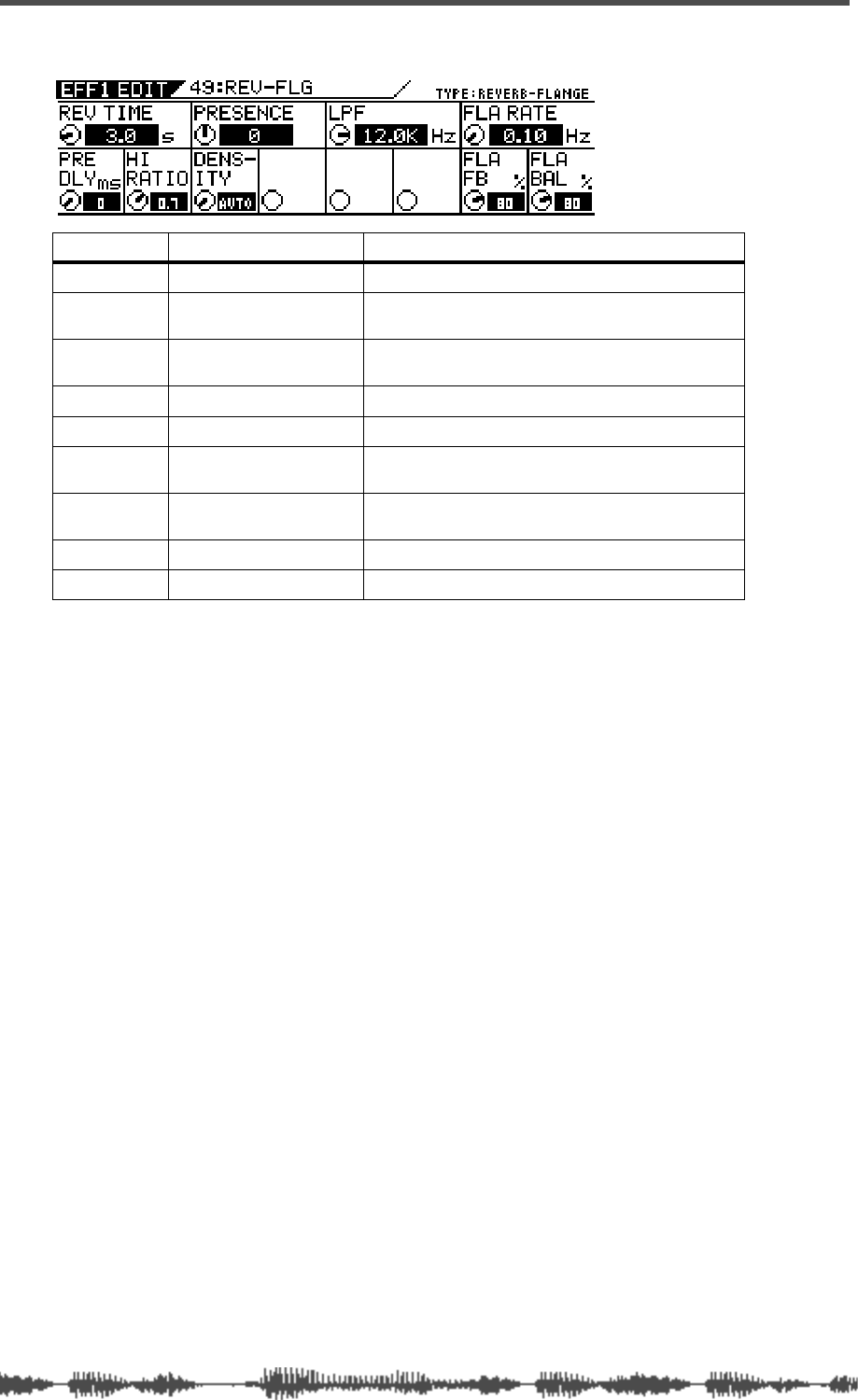
Effects
146 VM200 User’s Guide
REVERB-FLANGE (49)
Parameter Value Description
REV TIME 0.1–30.0 [s] (0.1 step) Length of the reverberation.
PRE DLY 0–160 [ms] (1 step) Delay time from the early reflections until the
reverb.
HI RATIO 0.1–1.0 (0.1 step) Length of the high frequency reverberation,
expressed as a ratio relative to REV.TIME.
PRESENCE -10–0–+10 (1 step)1
1. Brightness increases with a positive setting, and decreases with a negative setting.
Brightness in the high range of the reverb.
DENSITY 0–10, AUTO 2
2. With AUTO, the optimum value for the REV TIME setting will be used.
Density of the reverb.
LPF 1.00kHz–20.2kHz, THRU
(step: same as EQ) Cut-off frequency of the low pass filter.
FLA RATE 0.01–2.00 [Hz] (0.01 step) Modulation speed. (0.01 step when ENTER is
pressed.)
FLA FB 0–100 [%] (1 step) Feedback amount.
FLA BAL 0–100 [%] (1 step) Level of flange sound.

DIGITAL RECORDING MIXER
VM200
REC BUSS
EFF EDITSELECTED EQ
EQ/HI
EQ/HI-MIDEQ/LO-MID
+10
0
-10
-20
-30
-40
-
+10
0
-10
-20
-30
-40
-
+10
0
-10
-20
-30
-40
-
+10
0
-10
-20
-30
-40
-
+10
0
-10
-20
-30
-40
-
+10
0
-10
-20
-30
-40
-
+10
0
-10
-20
-30
-40
-
GAIN
FREQ
PAN
Q
PAN
ON ON ON ON ON ON ON
SOLO SOLO SOLO SOLO SOLO SOLO SOLO
EQ EDIT EQ EDIT EQ EDIT EQ EDIT EQ EDIT EQ EDIT EQ EDIT EQ EDIT
SOLO
ON ON
SOLO
EQ LIBRARY
STORERECALL
EQ ON
EFF LIBRARY
STORERECALL
EFF2EFF1
RECALLSOLO
EXIT
14
6
13
5
12
4
11
3
2019
FREQ QFREQ Q
Q
GAINGAIN
9-16 ADAT IN 17-20 EFF RTN
P
AGE SELECT
GROUP
PAIR/
METER
CHANNEL/
MIN MAX
+10
0
1
0
1
0
0
-10
-20
-30
-60
-
-40
MMC SEND
PANPANPANPANPANPAN
-40
-36
-24
-18
1212
ST BUSS/SOLO
L R
VM200 User’s Guide
147
CHAPTER 9
Scene Memory
About This Chapter
This chapter describes Scene Memory and explains how to store
and recall scenes and how to prevent specific parameters from
being updated by a scene recalled from memory.
Chapter Contents
What is Scene Memory? . . . . . . . . . . . . . . . . . . . . . . . . . . 148
Scene Edit Indicator . . . . . . . . . . . . . . . . . . . . . . . . . . . 149
What Can You Store in a Scene?. . . . . . . . . . . . . . . . . . 149
Preset Scene Memory . . . . . . . . . . . . . . . . . . . . . . . . . . 150
Recalling Mix Scenes . . . . . . . . . . . . . . . . . . . . . . . . . . . . 151
Recalling a Scene Manually . . . . . . . . . . . . . . . . . . . . . 151
Recalling a Scene Automatically at Start-up . . . . . . . . . 151
Recalling Mix Scenes Using MIDI Program Change Messages. 152
Motorized Faders . . . . . . . . . . . . . . . . . . . . . . . . . . . . . 153
Storing Mix Scenes . . . . . . . . . . . . . . . . . . . . . . . . . . . . . 154
Editing Scene Memory Titles. . . . . . . . . . . . . . . . . . . . . . . 156
Recall Safe Function. . . . . . . . . . . . . . . . . . . . . . . . . . . . . 156
Specifying Recall Safe Channels . . . . . . . . . . . . . . . . . . . . 156
Specifying Recall Safe Parameters. . . . . . . . . . . . . . . . . . . 157
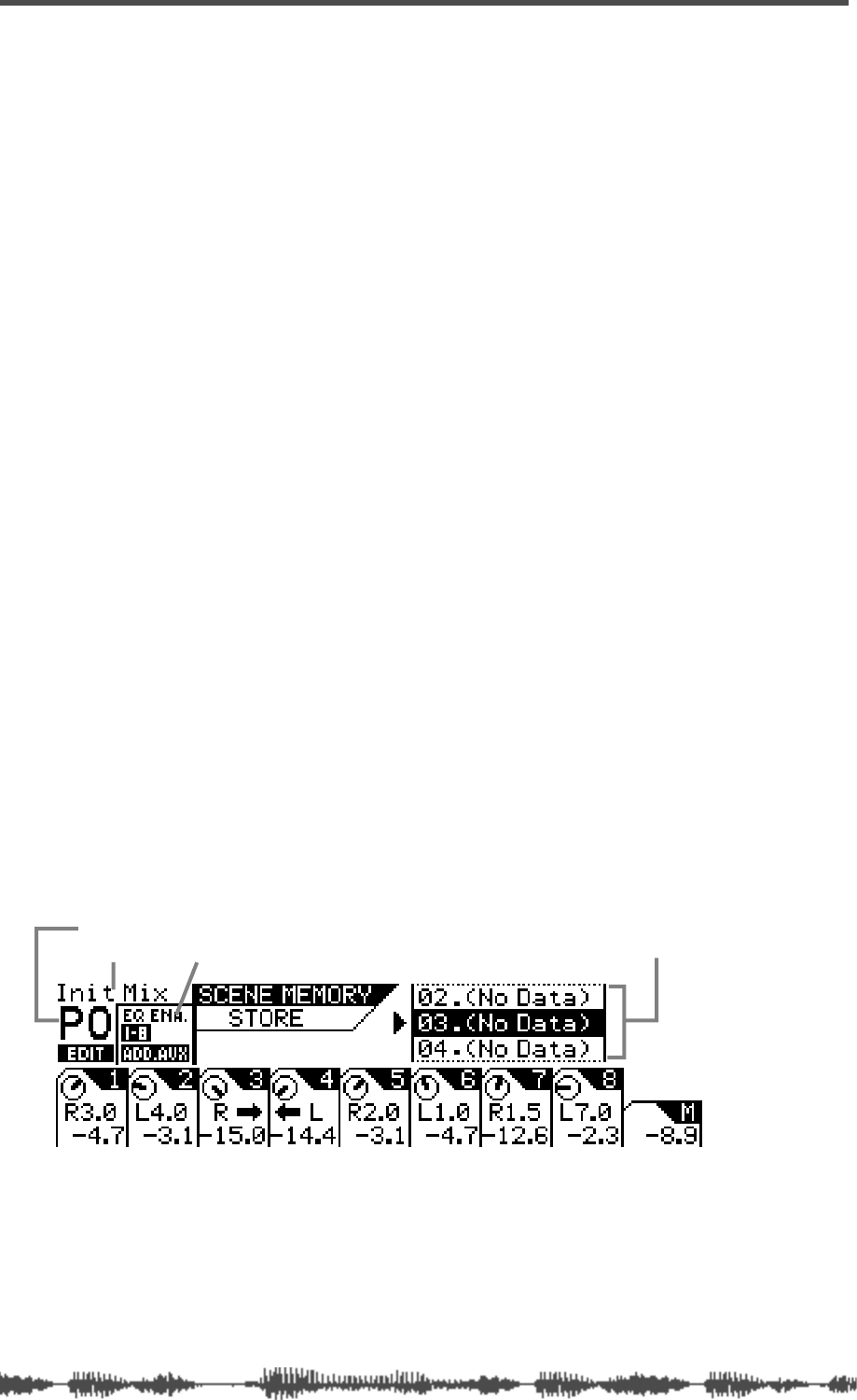
Scene Memory
148
VM200 User’s Guide
What is Scene Memory?
“Scene Memory” refers to specific locations in the flash memory of
the VM200 in which you can store mix scenes. A mix scene is a
snapshot of settings for virtually all VM200 parameters (i.e., EQ,
fader positions, effects, and so on) at a given point in time.
Say you have finally arrived at the perfect mix setting for recording a
particular instrumentalist in your studio. It sounds great, but next
week you want to be able to recall the same settings. Simply store the
scene into the Scene Memory, and recall it next week. This is one of
the principle advantages of a digital recording mixer.
The VM200 features 100 (0–99) scene memories. You can assign a
name to each one.
The VM200 also features three preset scenes: P0 [Init Mix], P1
[Recording], and P2 [Mix Down]. These are useful for common mixing
situations.
You can set individual channels or parameters as “recall safe.” This
means that when you recall a new scene from memory, the settings
for the specified channels or parameters remain unchanged.
You can store and recall scene memories in three ways:
❑
By pressing the
[RECALL]
key in the Scene Memory section and
selecting a scene;
❑
By programming the VM200 to automatically recall a scene when
the VM200 is powered on;
❑
By sending remote MIDI Program Change messages from a com-
puter or MIDI sequencer (see “Program Change To Scene Memory
Assignment Tables” on page 210).
You can also back up scene memory data to an external MIDI device
using MIDI Bulk Dump messages. See “Bulk Dump” on page 189 for
more information.
You store scenes using the
SCENE MEMORY STORE
function page, and
recall them using the
SCENE MEMORY RECALL
function page. On both
pages, you will utilize the Scene Memory
[STORE]
and
[RECALL]
keys.
The
SCENE MEMORY STORE
function page includes the following informa-
tion:
❑
current scene name and number (in the above example, “P0”
means “Preset 0”)
❑
EQ-enabled channel layers in the current scene
❑
a scrollable list of scene names and numbers
scene name
scene number
EQ Enable indicator scrollable list of scene names and numbers
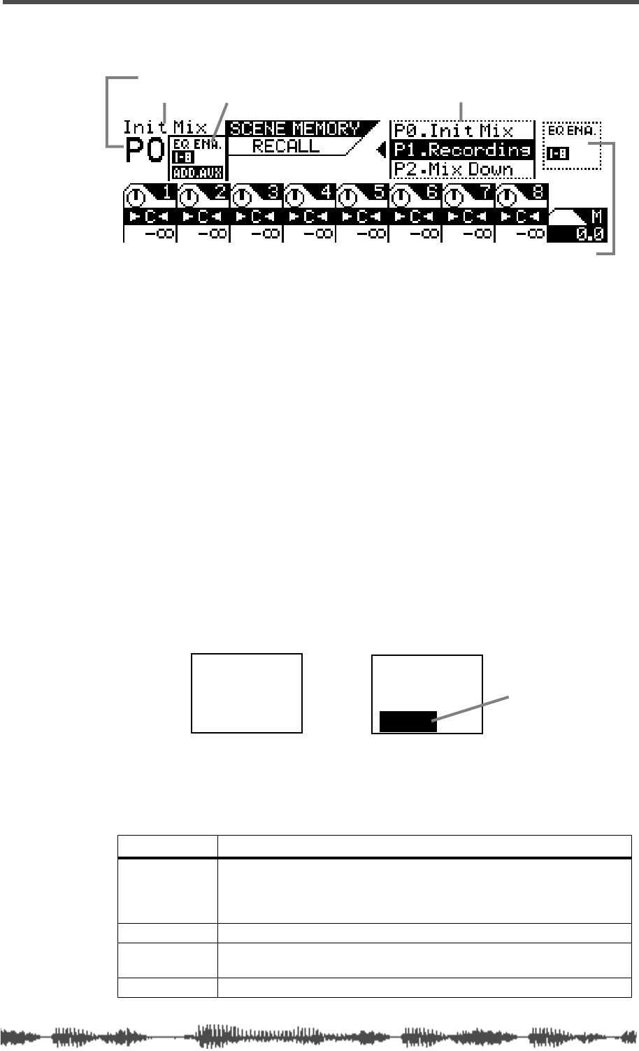
Scene Edit Indicator
VM200 User’s Guide
149
The bottom half of the function page is identical to the
CHANNEL EDIT
func-
tion page, displaying PAN controls for each channel in the current layer.
The
SCENE MEMORY RECALL
function page includes the following informa-
tion:
❑
current scene name and number (in the above example “P0” means
“Preset 0”)
❑
EQ-enabled channel layers in the current scene (left side of page)
❑
a scrollable list of scene memory location names and numbers
❑
EQ-enabled channel layers in the scene selected in the list (right
side of page)
❑
the bottom half of the function page is identical to the Channel Edit
function page. It displays PAN controls for each channel in the cur-
rent layer. Adjustments you make to the PAN controls will be saved
with the scene.
Scene Edit Indicator
The VM200 features an EDIT indicator that lights up when you
adjust any parameter in the scene, indicating that the current scene
no longer exactly matches the parameters of the scene you recalled.
What Can You Store in a Scene?
You can store the following VM200 mix settings in a scene:
Section Items
Channel
(ch1–ch20)
Ch fader, Ch on, Ch pan, AUX1–4 sends, Eff1/2 sends, AUX1&2 pan,
AUX 3&4 pan, EQ/LO Gain/Freq/Q, EQ/LO-MID Gain/Freq/Q,
EQ/HI-MID Gain/Freq/Q, EQ/LO Gain/Freq/Q, EQ on, Routing, Phase,
Ch pair, Mute/Fader group, S/P DIF IN
Master ST Buss master/on, AUX1–4 master/on, Eff1/2 master/on
Scene Status EQ Enable, ADD AUX, AUX1–4 post/pre, Eff1/2 post/pre, AUX1&2 pair,
AUX3&4 pair
Others Scene name, Effects 1/2 selection
scene name
scene number
EQ Enable indicator scrollable list of scene names and numbers
EQ Enabled channel layer in selected scene
Init Mix
PO Init Mix
PO
EDIT
EDIT indicator
Scene Memory
150
VM200 UserÕs Guide
Preset Scene Memory
The VM200 includes three preset scenes: P0, P1, and P2.
These presets were designed as scenes you can quickly recall for
three common purposes:
❑
Init Mix: For initial mixing
❑
Recording: For a typical recording situation
❑
Mix Down: For mixing down
You can recall a preset scene, edit its parameters, and store it again
under a new name. However, you cannot overwrite the pre-pro-
grammed settings of a preset scene.
These preset programs are all quite similar; they differ only in the fol-
lowing settings and usage:
# Name EQ
Enable ADD.
AUX Routing Usage
P0
Init_Mix 1–8 ON 1–20:ST Buss Normal mixing application, such as
PA, live, etc.
P1
Recording 1–8 OFF 1–8:Rec Buss
9–20:ST Buss Overdubbing or bounce recording via
Rec Buss.
P2
Mix_Down 9–16 ON 1–20:ST Buss ADAT mixdown
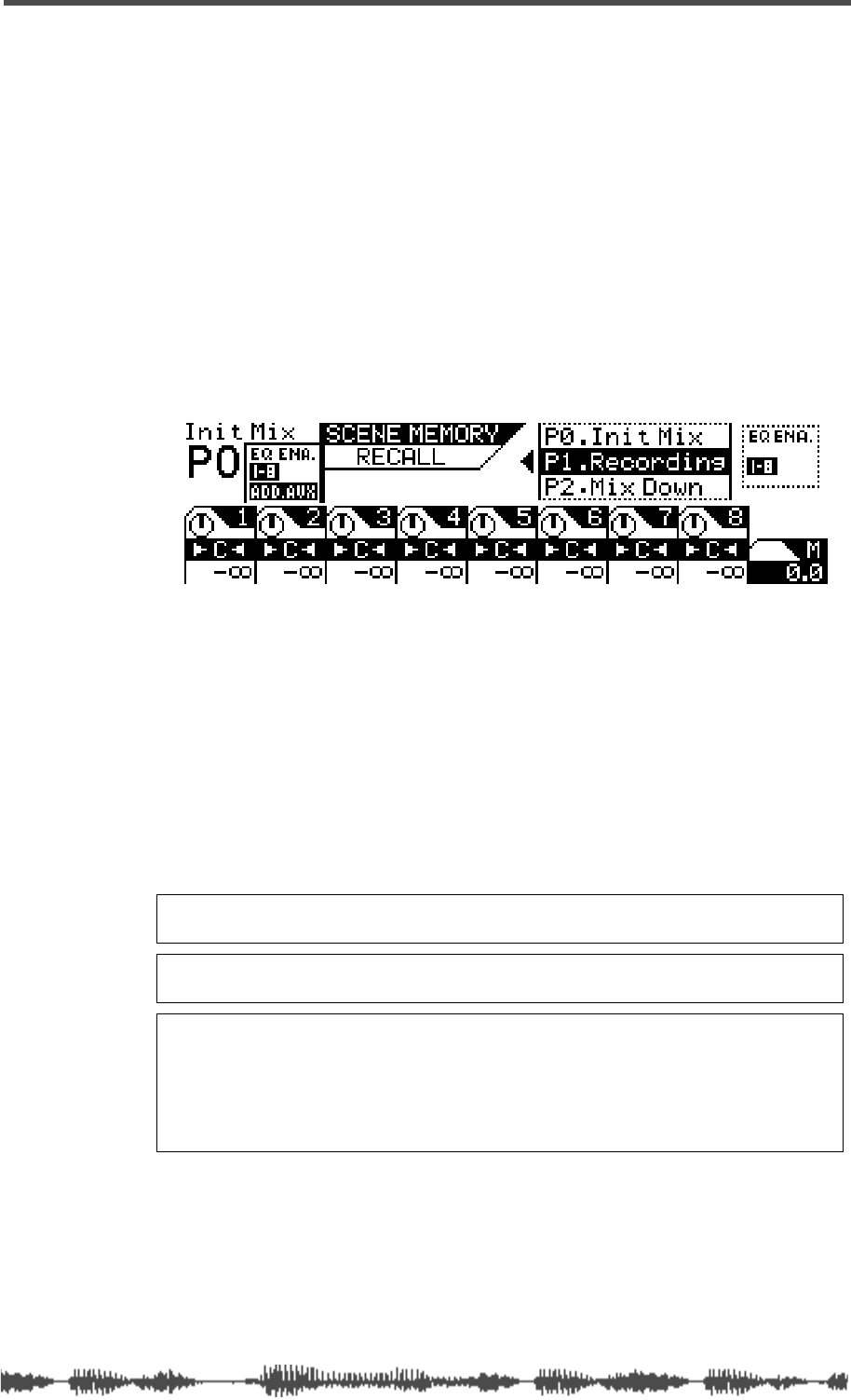
Recalling Mix Scenes
VM200 User’s Guide
151
Recalling Mix Scenes
You can recall scenes from Scene Memory in three ways:
❑
manually
❑
automatically, when the power is turned on to the VM200
❑
remotely using MIDI Program Change messages.
You can recall preset scenes P0, P1, or P2, or any scene that has been
saved to Scene Memory location 00 to 99.
Recalling a Scene Manually
1.
Press the Scene Memory
[RECALL]
key.
The VM200 displays the
SCENE MEMORY RECALL
function page.
2.
Use the Data Wheel or the
[</-1]
and
[+1/>]
keys to select a
scene.
The “EQ Enabled” readout on the right side of the display indi-
cates the channel layers for which EQ is enabled. The readout
changes to reflect the status of the scene highlighted by the cursor
in the scrolling list. Also, if the ADD.AUX parameter is turned on
for the selected scene program, “ADD.AUX” appears in this area of
the display. See “Enabling AUX Sends 3 & 4 (ADD. AUX Parame-
ter)” on page 115 for more information.
3.
Press the
[ENTER]
key to confirm the selection.
The VM200 loads the scene and returns to the previous mode.
Recalling a Scene Automatically at Start-up
You can specify a scene to be recalled automatically when you power
on the VM200. This is useful if you wish to start all sessions with a
particular scene, or if you wish to continue working with the current
scene in your next session.
Note:
You cannot recall scenes titled “NO_DATA, because there is no
data in the scene.
Note:
You can press the
[EXIT]
key to return to Channel Edit mode at
any time, cancelling the scene memory recall process.
Caution:
When you recall a scene, volume levels may suddenly change
because of changes in parameter values and fader settings. Before you
recall the scene, lower the Master Fader or turn down the Monitor and
Phones Gain controls as necessary to protect your ears and speakers.
Also, if the Motor parameter is turned on, the faders may suddenly move
automatically. Watch your fingers!
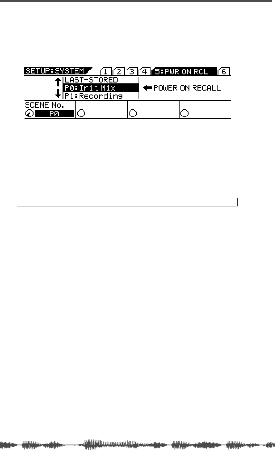
Scene Memory
152
VM200 User’s Guide
You can select one of the following options: LAST-STORED, P0, P1,
P2, 0–99. The default setting is “LAST-STORED,” which causes the
most-recently stored scene to be recalled.
1.
Press the
[SYSTEM]
key five times.
The VM200 displays the
5:PWR ON RCL
function page.
2.
Use the Data Wheel or the
[</-1]
and
[+1/>]
keys to select a
scene.
You can select one of the following:
❑
any Preset scene (P0, P1, P2)
❑
any User scene (0-99)
❑
LAST-STORED (the last scene you stored)
The selected item flashes in the Scene Number field in the lower
left corner.
3.
Press the
[ENTER]
key to confirm the selection.
The next time you power on the VM200, the selected scene will be
automatically recalled.
Recalling Mix Scenes Using MIDI Program Change Messages
You can use MIDI Program Change messages to recall scenes for
snapshot-style mix automation.
You can transmit Program Change messages from a computer, MIDI
sequencer, or MIDI keyboard. Most MIDI keyboards transmit a Pro-
gram Change message when a voice is selected. You can use this
message to recall a scene on the VM200. Using this technique, the
synthesizer and VM200 can be reconfigured instantaneously.
To recall scene memories using MIDI Program Change messages, do
the following:
1.
Connect the VM200 to MIDI equipment capable of transmit-
ting Program Change messages.
See “Connecting MIDI devices” on page 175 for more information.
2.
Configure the VM200 to receive MIDI Program Change mes-
sages.
See “Program Change Messages” on page 177 for more informa-
tion.
3.
Assign Program Change messages to scene memories.
See “Program Change To Scene Memory Assignment Tables” on
page 210 for more information.
Note:
Press the [EXIT] key at any time to cancel this process.
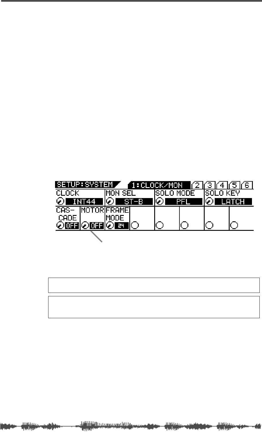
Motorized Faders
VM200 User’s Guide
153
If you have set the Program Change/Tx parameter to On, the VM200
transmits a Program Change message each time you recall a scene.
(The Program Change/Tx parameter appears on the Setup: MIDI
1:MIDI TX&RX
function page. See “Program Change Messages” on
page 177 for more information.) Using this capability, you can recall
programs on other MIDI equipment, such as a tone program on a syn-
thesizer. You can record transmission of Program Change messages
from the VM200 to a MIDI sequencer to later automate mix scene
changes. Refer to the “Using Program Change Messages to Recall
Scenes” on page 180 for more information.
Motorized Faders
In order for the faders to move to their new positions automatically
when you change scenes, the Motor parameter must be turned on.
The Motor parameter appears on the
SETUP: SYSTEM 1:CLOCK/MON
func-
tion page.
Follow the steps below to turn the motorized faders on or off.
1.
Press the
[SYSTEM]
key once to display the
1: CLOCK/MON
func-
tion page.
2.
Rotate the EQ/LO Q rotary control to turn the Motor parame-
ter on or off.
The default setting is “OFF.”
Warning:
Do not force the automated faders or you may damage the
VM200.
Note:
If the Motor parameter is turned on, the fader will move suddenly
and automatically when a new scene is recalled or the Fader Mode is
changed.
turning motorized faders on and off
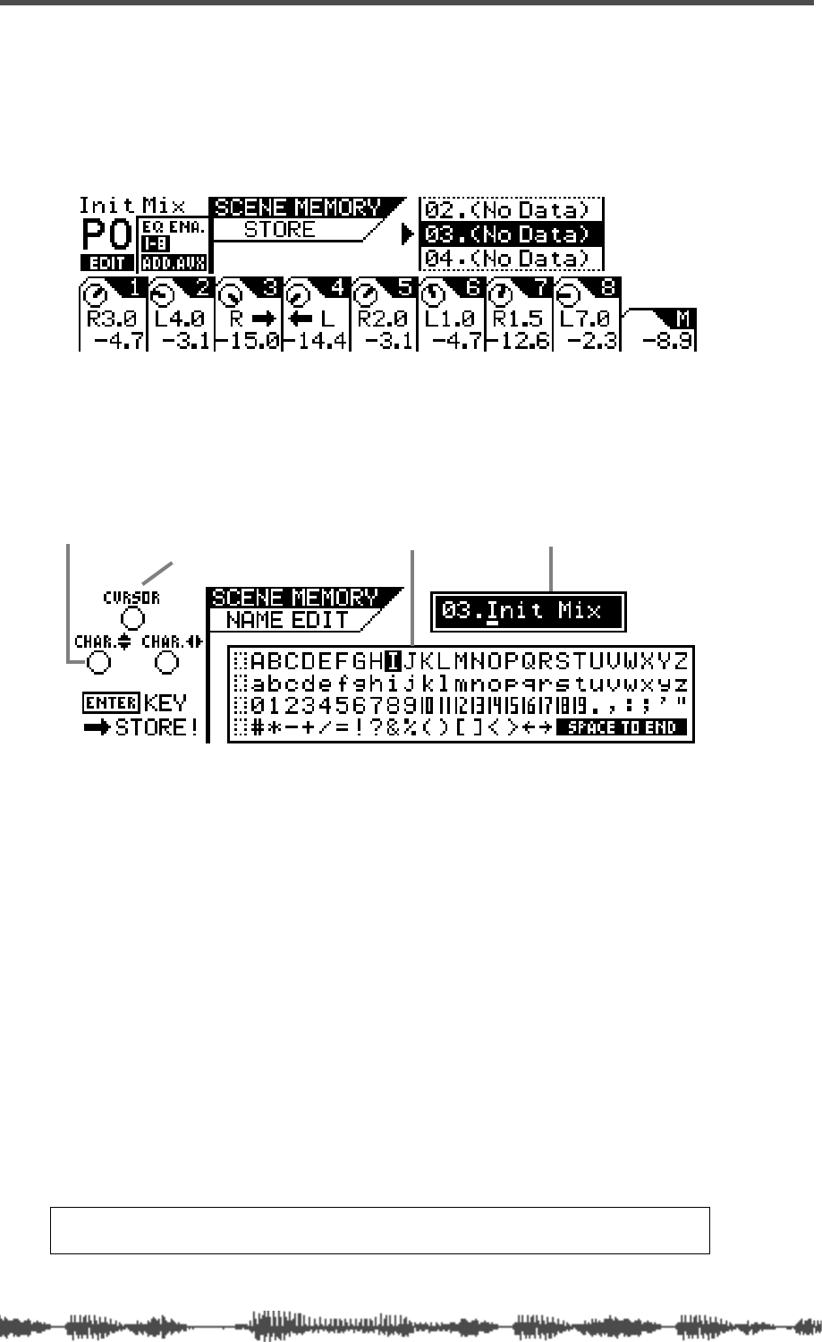
Scene Memory
154
VM200 User’s Guide
Storing Mix Scenes
You can store mix scenes in Scene memory locations 0–99.
1.
Press the Scene Memory
[STORE]
key.
The VM200 displays the
SCENE MEMORY STORE
function page.
2.
Use the Data Wheel or the
[</-1]
and
[+1/>]
keys to select a
scene memory location to which you wish to store the cur-
rent scene.
3.
Press the
[ENTER]
key.
The VM200 displays the
SCENE MEMORY NAME EDIT
function page.
The
SCENE MEMORY NAME EDIT
function page includes a character set
box that displays all the letters of the alphabet, as well as numer-
als and punctuation symbols. You can use these characters to
name or title the scene memory.
You can use any Gain, Freq, and Q rotary controls to select the
characters for the title.
The Gain rotary control moves the cursor position left and right in
the title box. The Freq rotary control moves the character-selector
up and down the matrix; the Q rotary control moves the charac-
ter-selector left and right.
You can also press the
[</-1]
and
[+1/>]
keys to move the cursor
and rotate the Data Wheel to select characters or numbers.
4.
Use the Freq and Q rotary controls to select a character, then
turn the Gain control one notch right to move the cursor to
the next space in the name, and repeat the process.
The “Space to End” option will complete your title with blank
spaces.
Note:
Press the
[EXIT]
key at any time to cancel this process and return
to Channel Edit mode.
character-selector title box
character set box
cursor
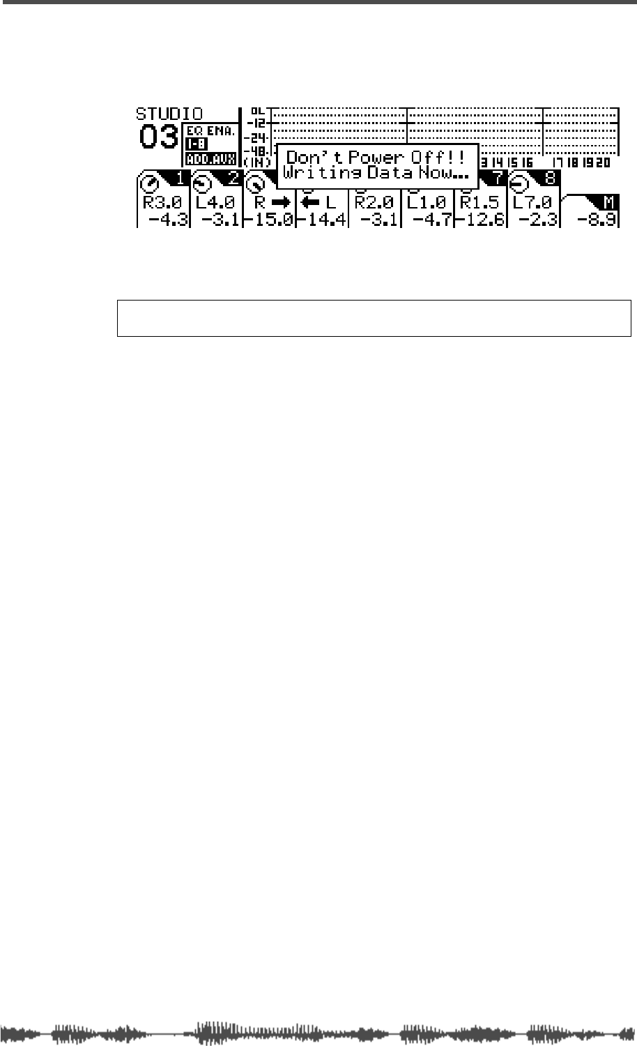
Storing Mix Scenes
VM200 User’s Guide
155
5.
When you’ve finished naming the scene, press the
[ENTER]
key.
The following warning message appears on the display.
The VM200 stores the scene into the selected Scene Memory loca-
tion and returns to the previous mode.
Warning:
Do not power off the VM200 while it is writing to the flash
memory or you may damage the system.

Scene Memory
156
VM200 User’s Guide
Editing Scene Memory Titles
You can edit scene names by recalling a scene and re-naming it.
Refer to the “Recalling Mix Scenes” on page 151 and “Storing Mix
Scenes” on page 154 for more information.
Recall Safe Function
When you recall a scene, all parameters are updated with settings
from the new scene. However, in some cases you may wish to retain
the settings for specific channels or parameters.
The VM200 features a Recall Safe function that enables you to desig-
nate channels and certain parameters as “recall safe.” When a new
scene is recalled, “safe” channels and parameters are not updated.
Recall Safe settings are available for each input channel 1-20 and for
the following parameters:
❑
Channel Fader
❑
Channel Pan
❑
Channel On
❑Routing
❑AUX1, AUX2, AUX3, AUX4
❑EFF1, EFF2
❑EQ
❑EQ On
You can specify safe channels using the CH RCL SAFE function page. You
can specify safe parameters on the RCL SAFE function page.
Specifying Recall Safe Channels
The VM200 features a Recall Safe function that enables you to desig-
nate input channels 1-20 as “recall safe.” When a new scene is
recalled, “safe” channels are not updated.
1. Press the [SYSTEM] key three times.
The VM200 displays the 3:CH RCL SAFE function page. All selectable
[EQ EDIT] keys flash.
2. Select a channel layer by pressing Page Select key [1–8 ANA-
LOG IN], [9–16 ADAT IN], or [17–20 EFF RTN].
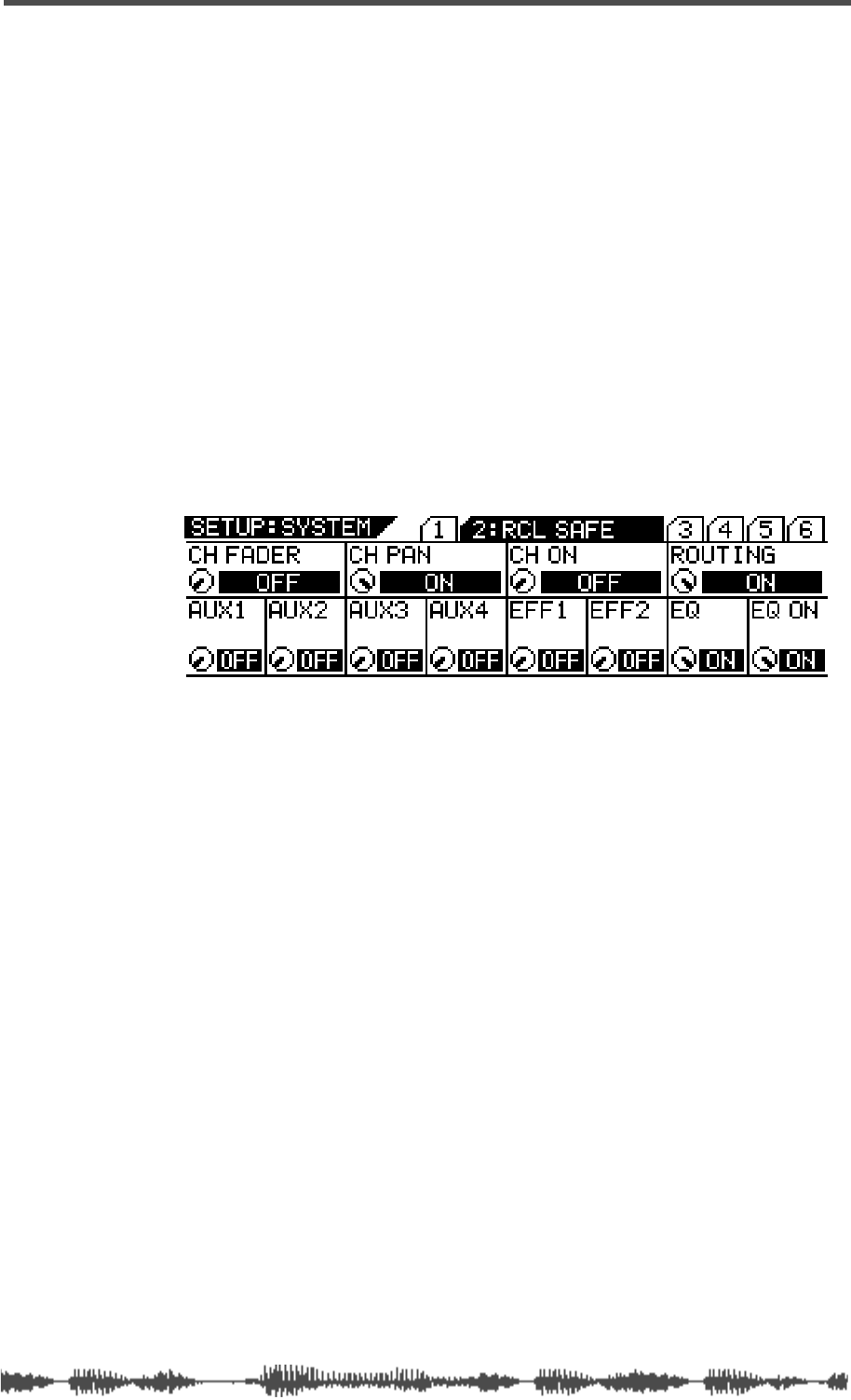
Specifying Recall Safe Parameters
VM200 User’s Guide 157
3. Press the [EQ EDIT] keys of target channels to designate them
“safe” from being overwritten by recalled parameters.
The [EQ EDIT] indicators of the recall safe channels light up, and
the [EQ EDIT] indicators of the non-safe channels continue to
flash.
The box indicators of the recall safe channels are highlighted.
4. Press the [CHANNEL/METER] key to return to Channel Edit
mode.
Specifying Recall Safe Parameters
The VM200 features a Recall Safe function that enables you to desig-
nate specific parameters as “recall safe.” When a new scene is
recalled, “safe” parameters are not updated.
1. Press the [SYSTEM] key three times.
The VM200 displays the 1:CH RCL SAFE function page.
2. Use the EQ Gain, Freq, and Q rotary controls for each parame-
ter to turn Recall Safe on or off.
The default setting is all Off.
3. Press the [CHANNEL/METER] key to return to Channel Edit
mode.

Scene Memory
158 VM200 User’s Guide
DIGITAL RECORDING MIXER
VM200
REC BUSS
EFF EDITSELECTED EQ
EQ/HI
EQ/HI-MIDEQ/LO-MID
+10
0
-10
-20
-30
-40
-
+10
0
-10
-20
-30
-40
-
+10
0
-10
-20
-30
-40
-
+10
0
-10
-20
-30
-40
-
+10
0
-10
-20
-30
-40
-
+10
0
-10
-20
-30
-40
-
+10
0
-10
-20
-30
-40
-
GAIN
FREQ
PAN
Q
PAN
ON ON ON ON ON ON ON
SOLO SOLO SOLO SOLO SOLO SOLO SOLO
EQ EDIT EQ EDIT EQ EDIT EQ EDIT EQ EDIT EQ EDIT EQ EDIT EQ EDIT
SOLO
ON ON
SOLO
EQ LIBRARY
STORERECALL
EQ ON
EFF LIBRARY
STORERECALL
EFF2EFF1
RECALLSOLO
EXIT
14
6
13
5
12
4
11
3
2019
FREQ QFREQ Q
Q
GAINGAIN
9-16 ADAT IN 17-20 EFF RTN
P
AGE SELECT
GROUP
PAIR/
METER
CHANNEL/
MIN MAX
+10
0
1
0
1
0
0
-10
-20
-30
-60
-
-40
MMC SEND
PANPANPANPANPANPAN
-40
-36
-24
-18
1212
ST BUSS/SOLO
L R
VM200 User’s Guide
159
CHAPTER 10
Digital Connections
About This Chapter
This chapter describes the VM200’s digital inputs and outputs,
including the ADAT and S/P DIF digital connectors, word clock
masters and slaves, and how to cascade multiple VM200s.
Chapter Contents
Digital Connections, Word Clocks, and Sample Rates . . . . 160
Word Clock Setup. . . . . . . . . . . . . . . . . . . . . . . . . . . . . . . 162
WORD IN/OUT Connectors. . . . . . . . . . . . . . . . . . . . . . 162
Setting the Master Word Clock . . . . . . . . . . . . . . . . . . . 162
Setting the VM200 as Master or Slave. . . . . . . . . . . . . . 163
Multitrack Recording and Mastering to a DAT. . . . . . . . 164
Digital I/Os . . . . . . . . . . . . . . . . . . . . . . . . . . . . . . . . . 165
Digital I/Os . . . . . . . . . . . . . . . . . . . . . . . . . . . . . . . . . . . 165
ADAT IN/OUT . . . . . . . . . . . . . . . . . . . . . . . . . . . . . . . 165
Using ADAT IN . . . . . . . . . . . . . . . . . . . . . . . . . . . . . . . 165
Using ADAT OUT . . . . . . . . . . . . . . . . . . . . . . . . . . . . . 166
Assigning Channels to ADAT DIRECT SENDs . . . . . . . . 166
S/P DIF IN/OUT. . . . . . . . . . . . . . . . . . . . . . . . . . . . . . 168
Using S/P DIF OUT . . . . . . . . . . . . . . . . . . . . . . . . . . . 168
Using S/P DIF IN . . . . . . . . . . . . . . . . . . . . . . . . . . . . . 169
Assigning S/P DIF Signals to Channels. . . . . . . . . . . . . 169
Cascading the VM200. . . . . . . . . . . . . . . . . . . . . . . . . . . . 171
Digital Connections
160
VM200 User’s Guide
Digital Connections, Word Clocks, and Sample Rates
The VM200 is equipped with two types of digital connectors: an
ADAT interface and S/P DIF In and Out connectors.
These connectors enable you to interface the VM200 to other digital
components in your recording studio. You can use the ADAT inter-
face to connect to any ADAT-compatible recorder, such as the FOS-
TEX VR800 or an Alesis ADAT. For more information “ADAT IN/OUT”
on page 165 and “S/P DIF IN/OUT” on page 168.
This section reviews some basic issues involved in setting up a digital
recording environment. (If you’ve worked with digital audio equipment
before, you are probably already familiar with word clock synchroni-
zation issues and can skip this section.)
The following illustration shows a typical waveform. Technically, this
graph represents
force
along the vertical axis (i.e., the force an audio
speaker requires to move a certain amount of air to create sound),
and
time
along the horizontal axis. The waveform is an analogy for the
soundwave position at specific points in time.
(Musically, however, this waveform could represent your next big hit :-)
A digital-to-analog (D/A) audio converter takes numerous tiny sam-
ples of such a waveform each second, and converts the sample data
to digital binary digital information.
The number of samples taken each second is called the “sample rate.”
The VM200, like many current digital devices, can sample at a rate of
44,100 times per second (44.1kHz) or 48,000 times per second
(48kHz).
Each time the converter samples the waveform, it records waveform
data as a binary number in a format called a “word.” A bit is a unit of
data, a single digit in a word, the “one-or-zero,” “on-or-off” funda-
mental encoding of the digital universe. For instance,
1011011110111001 is a 16-bit binary word. It contains 16 digits or
“bits” of data. If you are using 16-bit words, your system is said to
have a bit-rate of 16 bits. (This is also called the “bit resolution.”)
A word clock is a clock signal that you can use to synchronize all the
devices in a digital audio system. If the VM200 is the only digital
audio component in your studio, you don’t need to worry about set-
ting the word clock. (The VM200 will synchronize to its own internal
word clock.)
However, if you use a second digital device, such as a DAT or digital
multitrack recorder, you must designate one device the word clock
master
and the rest
slaves
. You may need to change word clock set-
tings on occasion, such as when you record from a DAT or CD player.
If the word clocks are not correctly synchronized throughout your
force
time

Digital Connections, Word Clocks, and Sample Rates
VM200 User’s Guide
161
system, noise or glitches may creep into your mixes.
Each device in a digital system may utilize a different word length,
because most digital devices are capable of interpreting words and
truncating or protracting their length.
However, it is important that every component in your digital audio
system do two things:
❑
utilize the same sample rate (44.1 or 48kHz)
❑
synchronize with a designated word clock master.
The word clock signal runs at the same frequency as the sampling
rate. The VM200 generates its own word clock at 44.1 kHz (the
industry-standard sampling rate for music CDs) and can be used as
the word clock master. (In general, if your work is destined for CD, it
is probably best to use the 44.1 kHz sampling rate.)
Alternatively, you can use the VM200 as a word clock slave synchro-
nized to an external word clock in the range of 44.1kHz to 48kHz,
+/-6%.
Be aware of the following word clock guidelines:
❑
You can distribute word clock signals via dedicated cables or derive
them from standard digital audio connections.
❑
If all devices share a common word clock, leave all the devices pow-
ered on, even if they’re not being used.
❑
First turn on the word clock master, then the slaves.
❑
When you shut down the system, first turn off the slaves, then the
master.
❑
Before a recording session, make sure that all word clock slaves are
synchronized to the master word clock.
For more information, refer to the documentation for each device.
Note:
Word clocks differ from SMPTE or MIDI timecode, which are used
to synchronize MIDI sequencers and audio recorders. Word clocks syn-
chronize the digital audio processing circuits in each digital audio device.
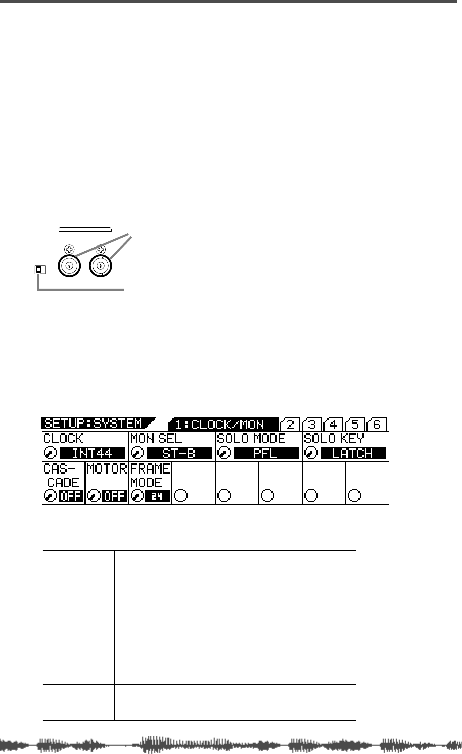
Digital Connections
162
VM200 UserÕs Guide
Word Clock Setup
The VM200’s internal word clock generator supports a sampling fre-
quency of 44.1kHz, the audio standard for music CDs.
You may also synchronize the VM200 to an external word clock.
WORD IN/OUT Connectors
These BNC connectors receive/transmit the word clock. You can
connect a device that has a WORD IN/OUT connector, such as the
Fostex VR800 digital multitrack recorder, to these connectors.
If the VM200 is the last device in the word clock chain, set the word
clock termination switch to ON.
Setting the Master Word Clock
Follow the steps below to set the master word clock.
1.
Press the
[SYSTEM]
key.
The VM200 displays the
SYSTEM
function page.
2.
Rotate the EQ/LO Gain control to select a master clock from
the following options:
INT44
Select this option to use the VM200 as the word clock
master.
ADAT44
Select this option to use the VM200 as a word clock slave,
syncing to the clock from an ADAT-compatible machine
running at 44.1kHz.
ADAT48
Select this option to use the VM200 as a word clock slave,
syncing to the clock from an ADAT-compatible pro audio
machine running at 48kHz.
S/PDIF44
Select this option to use the VM200 as a word clock slave,
syncing to the clock from a CD player or S/PDIF-compati-
ble machine running at 44.1kHz.
S/PDIF48
Select this option to use the VM200 as a word clock slave,
syncing to the clock from a connected CD player or
S/P DIF-compatible machine running at 48kHz.
WORD IN/OUT
WORD
OUTIN
75
OFFON
word clock termination switch
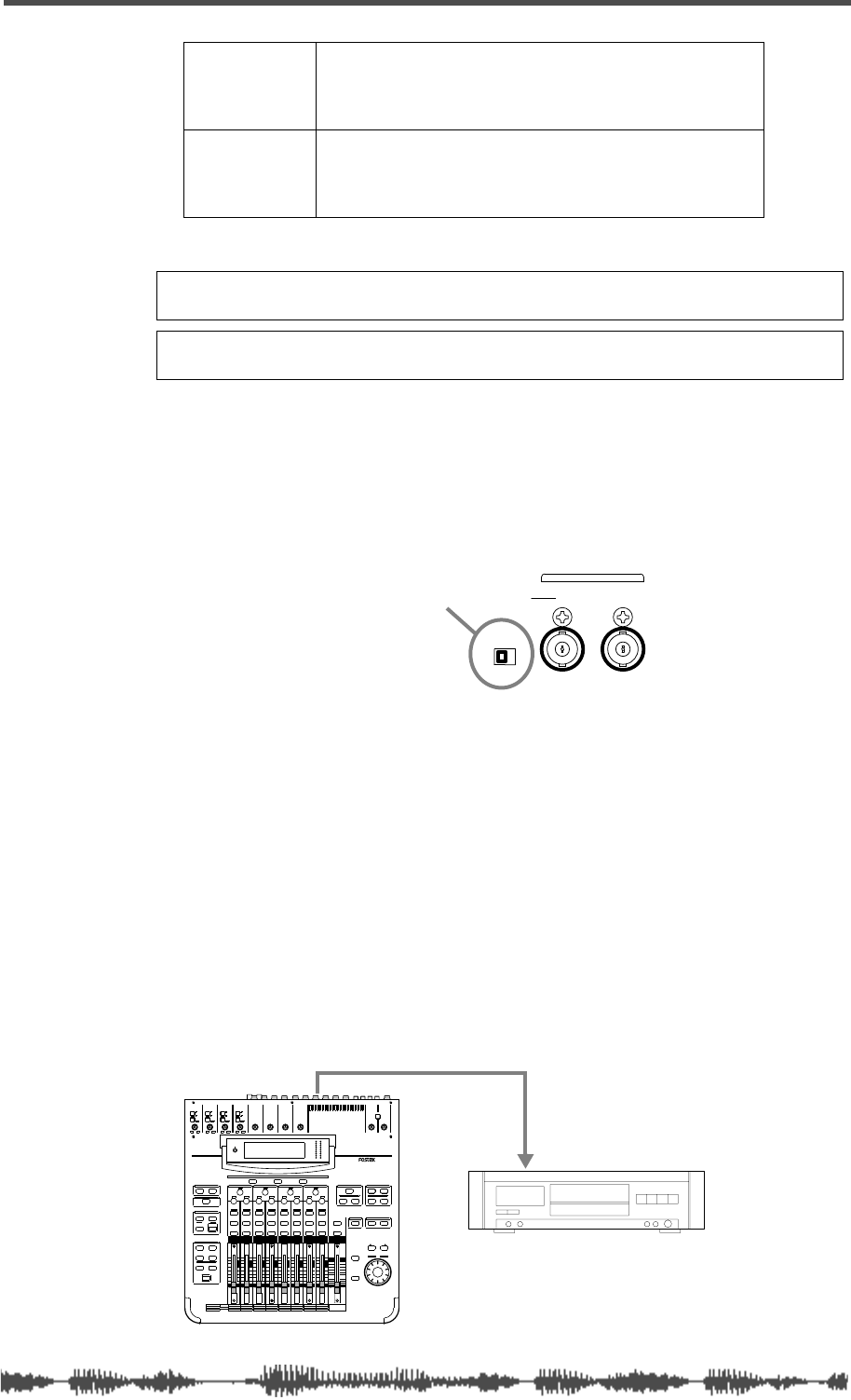
Setting the VM200 as Master or Slave
VM200 User’s Guide
163
3.
Press the
[ENTER]
key to confirm your selection.
The VM200 displays the previous function page.
4.
If you select any option other than “INT44” in step 2, and the
VM200 is the last device in the word clock chain, turn the
WORD IN Termination ON/OFF switch to ON on the rear
panel.
Setting the VM200 as Master or Slave
The following examples illustrate the VM200 in various recording
configurations, being used as both word clock master and word clock
slave.
Recording to a Digital Multitrack Recorder or DAT
In this example, a stereo signal is recorded to a DAT recorder. The
VM200 is the word clock master; the DAT recorder is the word clock
slave. Set the Master Word Clock parameter on the VM200 to “INT44.”
The VM200 will generate the word clock and the DAT recorder will
slave to it.
VM200 is the word clock MASTER
WORD44
Select this option to use the VM200 as a word clock slave,
syncing to the clock from a connected FOSTEX VR800
digital multitrack recorder, or a digital device equipped with
a WORD OUT connector, running at 44.1kHz.
WORD48
Select this option to use the VM200 as a word clock slave,
syncing to the clock coming from a connected digital
device equipped with a WORD OUT connector that is run-
ning at 48kHz.
Caution:
Selecting an inappropriate sampling frequency will interfere
with normal recording and playback.
Note:
If the VM200 is only the digital device in your system, use the
default setting of INT44.
WORD
OUTIN
75
OFFON
WORD IN Termination ON/OFF switch
DIGITAL INPUT
S/PDIF OUT
INPUT 4INPUT 3INPUT 2INPUT 1
PAD
26dB
A
B
PAD
26dB
A
B
PAD
26dB
A
B
PAD
26dB
A
B
-16 -60
+10 -34
-16 -60
+10 -34
-16 -60 -16 -60
TRIMTRIMTRIMTRIM
DIGITAL RECORDING MIXER
VM200
SCENE MEMORYREC BUSS
EFF EDITSELECTED EQ
EQ/HI
EQ/HI-MIDEQ/LO-MIDEQ/LOSETUP
CURRENT SCENE STATUS
KEY MODE
+10
0
-10
-20
-30
-40
-
+10
0
-10
-20
-30
-40
-
+10
0
-10
-20
-30
-40
-
+10
0
-10
-20
-30
-40
-
+10
0
-10
-20
-30
-40
-
+10
0
-10
-20
-30
-40
-
+10
0
-10
-20
-30
-40
-
16
8
GAIN
FREQ
PAN
Q
PAN
ON ON ON ON ON ON ON
SOLO SOLO SOLO SOLO SOLO SOLO SOLO
EQ EDIT EQ EDIT EQ EDIT EQ EDIT EQ EDIT EQ EDIT EQ EDIT EQ EDIT
SOLO
ON ON
SOLO
EQ LIBRARY
STORERECALL
EQ ON
EFF LIBRARY
STORERECALL
EFF2EFF1
STORERECALLSOLO
+1/ /-1
DATA
EXIT
ENTER
MASTER
15
7
14
6
13
5
12
4
11
3
10
2
9
1
2019
18
17
FREQ QFREQ Q
FREQ Q
GAINGAINGAIN
1-8 ANALOG IN 9-16 ADAT IN 17-20 EFF RTN
PAGE SELECT
SYSTEM MIDI
PHASE GROUP
ROUTING/ PAIR/
CH VIEW METER
CHANNEL/
AUX1
FADER MODE
AUX2
AUX3 AUX4
EFF1 EFF2
CHANNEL
ADD.AUX
TRIM
-10 -50
TRIM TRIM TRIM
-10 -50 -10 -50 -10 -50
INPUT 5 INPUT 6 INPUT 7 INPUT 8
MIN MAX
GAIN
MAXMIN
GAIN
2TRK IN
PHONESMONITOR
+10
0
-10
-20
-30
-40
-
EFF RTN
ADAT IN
ANALOG IN
0
-10
-20
-30
-60
-
-40
MMC SEND
PANPANPA NPA NPA NPAN
-48
-36
-24
-18
-12
-9
-6
-3
OL
ST BUSS/SOLO
LR
METER
+10 -34 +10 -34
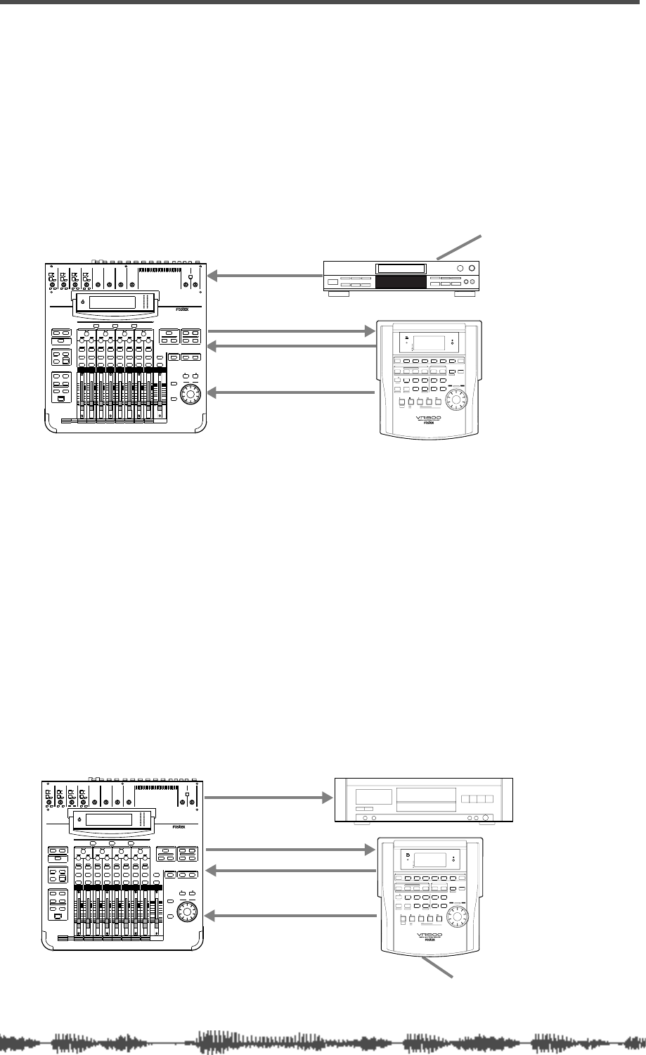
Digital Connections
164
VM200 User’s Guide
Mixing a CD Source and Recording to a Digital Multitrack Recorder
In this example, a signal from a CD player is mixed with a signal from
an ADAT-compatible digital multitrack recorder, such as the Fostex
VR800, and recorded to the digital multitrack recorder.
The CD player serves as the word clock master, and uses a sampling
frequency of 44.1kHz. The VM200 and the digital multitrack recorder
are word clock slaves, both syncing to the CD player word clock.
Set the Master Word Clock parameter on the VM200 to “SPDIF44.”
The VM200 is word clock SLAVE.
Multitrack Recording and Mastering to a DAT
In this example, an audio signal is recorded to an ADAT-compatible
digital multitrack recorder, such as the Fostex VR800, while also
being mixed from the digital multitrack, and sent to a DAT master
recorder.
The digital multitrack recorder is the word clock master. The VM200
and the DAT machine slave to it.
Set the Master Word Clock parameter on the VM200 to “ADAT44” or
“ADAT 48,” depending on the sampling frequency of the digital mul-
titrack recorder.
(If you are using the Fostex VR800 digital multitrack recorder, set this
parameter to “ADAT44.”)
The VM200 is word clock SLAVE.
S/PDIF IN
S/PDIF OUT
ADAT OUT
ADAT IN
Digital in
Digital out
Word Clock Master
WORD IN WORD OUT
INPUT 4INPUT 3INPUT 2INPUT 1
PAD
26dB
A
B
PAD
26dB
A
B
PAD
26dB
A
B
PAD
26dB
A
B
-16 -60
+10 -34
-16 -60
+10 -34
-16 -60 -16 -60
TRIMTRIMTRIMTRIM
DIGITAL RECORDING MIXER
VM200
SCENE MEMORYREC BUSS
EFF EDITSELECTED EQ
EQ/HI
EQ/HI-MIDEQ/LO-MIDEQ/LOSETUP
CURRENT SCENE STATUS
KEY MODE
+10
0
-10
-20
-30
-40
-
+10
0
-10
-20
-30
-40
-
+10
0
-10
-20
-30
-40
-
+10
0
-10
-20
-30
-40
-
+10
0
-10
-20
-30
-40
-
+10
0
-10
-20
-30
-40
-
+10
0
-10
-20
-30
-40
-
16
8
GAIN
FREQ
PAN
Q
PAN
ON ON ON ON ON ON ON
SOLO SOLO SOLO SOLO SOLO SOLO SOLO
EQ EDIT EQ EDIT EQ EDIT EQ EDIT EQ EDIT EQ EDIT EQ EDIT EQ EDIT
SOLO
ON ON
SOLO
EQ LIBRARY
STORERECALL
EQ ON
EFF LIBRARY
STORERECALL
EFF2EFF1
STORERECALLSOLO
+1/ /-1
DATA
EXIT
ENTER
MASTER
15
7
14
6
13
5
12
4
11
3
10
2
9
1
2019
18
17
FREQ QFREQ Q
FREQ Q
GAINGAINGAIN
1-8 ANALOG IN 9-16 ADAT IN 17-20 EFF RTN
PAGE SELECT
SYSTEM MIDI
PHASE GROUP
ROUTING/ PAIR/
CH VIEW METER
CHANNEL/
AUX1
FADER MODE
AUX2
AUX3 AUX4
EFF1 EFF2
CHANNEL
ADD.AUX
TRIM
-10 -50
TRIM TRIM TRIM
-10 -50 -10 -50 -10 -50
INPUT 5 INPUT 6 INPUT 7 INPUT 8
MIN MAX
GAIN
MAXMIN
GAIN
2TRK IN
PHONESMONITOR
+10
0
-10
-20
-30
-40
-
EFF RTN
ADAT IN
ANALOG IN
0
-10
-20
-30
-60
-
-40
MMC SEND
PANPANPA NPA NPA NPAN
-48
-36
-24
-18
-12
-9
-6
-3
OL
ST BUSS/SOLO
LR
METER
+10 -34 +10 -34
SHIFT P.EDIT LOC MEM
RECORD STOP PLAY REW F FWD
AUTO PUNCH
CLIPBOARD
AUTO RTN
OUTIN
ENDOUTINSTART
EJECT
ACCESS
5678
OL
24
12
6
0
1234
RECORD TRACK
4321 5 678
EXECUTE
/ YES
EXIT
/ NO
DISP SEL
UNDO / REDO
EDITHOLD/ STORE SETUP
JOG
VARI PITCH SCRUBLOCATEAUTO PLAY
PGM SEL
AUTO RTN TIME BASE SEL SHUTTLE
LOCATE REC END
LOCATE ABS 0
CLIPBOARD PLAY
PUNCH
AUTO
OPTICAL
A SYNC
PREVIEW
Digital MTR
CD player
S/PDIF OUT
S/PDIF IN
ADAT OUT
ADAT IN
Digital in
Digital out
Word Clock Master
WORD IN WORD OUT
INPUT 4INPUT 3INPUT 2INPUT 1
PAD
26dB
A
B
PAD
26dB
A
B
PAD
26dB
A
B
PAD
26dB
A
B
-16 -60
+10 -34
-16 -60
+10 -34
-16 -60 -16 -60
TRIMTRIMTRIMTRIM
DIGITAL RECORDING MIXER
VM200
SCENE MEMORYREC BUSS
EFF EDITSELECTED EQ
EQ/HI
EQ/HI-MIDEQ/LO-MIDEQ/LOSETUP
CURRENT SCENE STATUS
KEY MODE
+10
0
-10
-20
-30
-40
-
+10
0
-10
-20
-30
-40
-
+10
0
-10
-20
-30
-40
-
+10
0
-10
-20
-30
-40
-
+10
0
-10
-20
-30
-40
-
+10
0
-10
-20
-30
-40
-
+10
0
-10
-20
-30
-40
-
16
8
GAIN
FREQ
PAN
Q
PAN
ON ON ON ON ON ON ON
SOLO SOLO SOLO SOLO SOLO SOLO SOLO
EQ EDIT EQ EDIT EQ EDIT EQ EDIT EQ EDIT EQ EDIT EQ EDIT EQ EDIT
SOLO
ON ON
SOLO
EQ LIBRARY
STORERECALL
EQ ON
EFF LIBRARY
STORERECALL
EFF2EFF1
STORERECALLSOLO
+1/ /-1
DATA
EXIT
ENTER
MASTER
15
7
14
6
13
5
12
4
11
3
10
2
9
1
2019
18
17
FREQ QFREQ Q
FREQ Q
GAINGAINGAIN
1-8 ANALOG IN 9-16 ADAT IN 17-20 EFF RTN
PAGE SELECT
SYSTEM MIDI
PHASE GROUP
ROUTING/ PAIR/
CH VIEW METER
CHANNEL/
AUX1
FADER MODE
AUX2
AUX3 AUX4
EFF1 EFF2
CHANNEL
ADD.AUX
TRIM
-10 -50
TRIM TRIM TRIM
-10 -50 -10 -50 -10 -50
INPUT 5 INPUT 6 INPUT 7 INPUT 8
MIN MAX
GAIN
MAXMIN
GAIN
2TRK IN
PHONESMONITOR
+10
0
-10
-20
-30
-40
-
EFF RTN
ADAT IN
ANALOG IN
0
-10
-20
-30
-60
-
-40
MMC SEND
PANPANPA NPA NPA NPAN
-48
-36
-24
-18
-12
-9
-6
-3
OL
ST BUSS/SOLO
LR
METER
+10 -34 +10 -34
SHIFT P.EDIT LOC MEM
RECORD STOP PLAY REW F FWD
AUTO PUNCH
CLIPBOARD
AUTO RTN
OUTIN
ENDOUTINSTART
EJECT
ACCESS
5678
OL
24
12
6
0
1234
RECORD TRACK
4321 5 678
EXECUTE
/ YES
EXIT
/ NO
DISP SEL
UNDO / REDO
EDITHOLD/ STORE SETUP
JOG
VARI PITCH SCRUBLOCATEAUTO PLAY
PGM SEL
AUTO RTN TIME BASE SEL SHUTTLE
LOCATE REC END
LOCATE ABS 0
CLIPBOARD PLAY
PUNCH
AUTO
OPTICAL
A SYNC
PREVIEW
Digital MTR
DAT
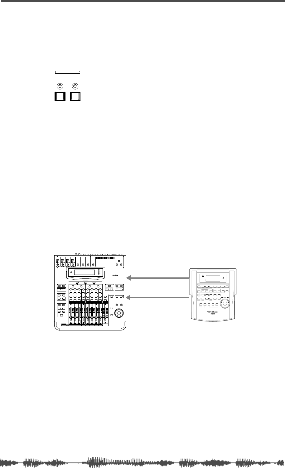
Digital I/Os
VM200 UserÕs Guide
165
Digital I/Os
The VM200 features two types of digital ins and outs: ADAT IN/OUT
and S/PDIF IN/OUT.
ADAT IN/OUT
ADAT is a digital audio format developed by the Alesis Corporation
that enables eight channels of digital audio to flow through a single
optical cable.
It includes eight digital inputs and eight assignable digital outputs
and can be directly connected to digital multitrack recorders.
You can connect any ADAT-compatible recorder to these connectors,
including an Alesis ADAT, Alesis ADAT-XT, Fostex VR-800, and others.
Using ADAT IN
You can use an optical cable to connect the ADAT IN connector on the
VM200 to the ADAT Out connector on an Alesis ADAT or other
ADAT-compatible device, such as the Fostex VR800.
The signal, which carries eight-channel data from the ADAT IN con-
nector, will be assigned to input channels 9 through 16 on the VM200.
In this example, a Fostex VR800 is connected to the ADAT IN con-
nector on the VM200 to mix from a digital source.
The VR800 serves as the word clock master; the VM200 is the word
clock slave. The VR800 WORD OUT connector transmits the word
clock to the WORD IN connector on the VM200.
Set the Word Clock parameter on the VM200 to “WORD44,” and make
sure that the WORD IN switch on the rear panel is turned on.
If a connected ADAT-compatible device does not have a WORD OUT
connector, set the Word Clock parameter on the VM200 to “ADAT44”
or “ADAT48” depending on the sampling frequency of the source.
For more information on the master word clock setup, refer to “Setting
the Master Word Clock” on page 162.
IN OUT
ADAT
ADAT IN
DATA OUT
.
WORD IN
WORD OUT
VR800
INPUT 4INPUT 3INPUT 2INPUT 1
PAD
26dB
A
B
PAD
26dB
A
B
PAD
26dB
A
B
PAD
26dB
A
B
-16 -60
+10 -34
-16 -60
+10 -34
-16 -60 -16 -60
TRIMTRIMTRIMTRIM
DIGITAL RECORDING MIXER
VM200
SCENE MEMORYREC BUSS
EFF EDITSELECTED EQ
EQ/HI
EQ/HI-MIDEQ/LO-MIDEQ/LOSETUP
CURRENT SCENE STATUS
KEY MODE
+10
0
-10
-20
-30
-40
-
+10
0
-10
-20
-30
-40
-
+10
0
-10
-20
-30
-40
-
+10
0
-10
-20
-30
-40
-
+10
0
-10
-20
-30
-40
-
+10
0
-10
-20
-30
-40
-
+10
0
-10
-20
-30
-40
-
16
8
GAIN
FREQ
PAN
Q
PAN
ON ON ON ON ON ON ON
SOLO SOLO SOLO SOLO SOLO SOLO SOLO
EQ EDIT EQ EDIT EQ EDIT EQ EDIT EQ EDIT EQ EDIT EQ EDIT EQ EDIT
SOLO
ON ON
SOLO
EQ LIBRARY
STORERECALL
EQ ON
EFF LIBRARY
STORERECALL
EFF2EFF1
STORERECALLSOLO
+1/ /-1
DATA
EXIT
ENTER
MASTER
15
7
14
6
13
5
12
4
11
3
10
2
9
1
2019
18
17
FREQ QFREQ Q
FREQ Q
GAINGAINGAIN
1-8 ANALOG IN 9-16 ADAT IN 17-20 EFF RTN
PAGE SELECT
SYSTEM MIDI
PHASE GROUP
ROUTING/ PAIR/
CH VIEW METER
CHANNEL/
AUX1
FADER MODE
AUX2
AUX3 AUX4
EFF1 EFF2
CHANNEL
ADD.AUX
TRIM
-10 -50
TRIM TRIM TRIM
-10 -50 -10 -50 -10 -50
INPUT 5 INPUT 6 INPUT 7 INPUT 8
MIN MAX
GAIN
MAXMIN
GAIN
2TRK IN
PHONESMONITOR
+10
0
-10
-20
-30
-40
-
EFF RTN
ADAT IN
ANALOG IN
0
-10
-20
-30
-60
-
-40
MMC SEND
PANPANPA NPA NPA NPAN
-48
-36
-24
-18
-12
-9
-6
-3
OL
ST BUSS/SOLO
LR
METER
+10 -34 +10 -34
SHIFT P.EDIT LOC MEM
RECORD STOP PLAY REW F FWD
AUTO PUNCH
CLIPBOARD
AUTO RTN
OUTIN
ENDOUTINSTART
EJECT
ACCESS
5678
OL
24
12
6
0
1234
RECORD TRACK
4321 5 678
EXECUTE
/ YES
EXIT
/ NO
DISP SEL
UNDO / REDO
EDITHOLD/ STORE SETUP
JOG
VARI PITCH SCRUBLOCATEAUTO PLAY
PGM SEL
AUTO RTN TIME BASE SEL SHUTTLE
LOCATE REC END
LOCATE ABS 0
CLIPBOARD PLAY
PUNCH
AUTO
OPTICAL
A SYNC
PREVIEW
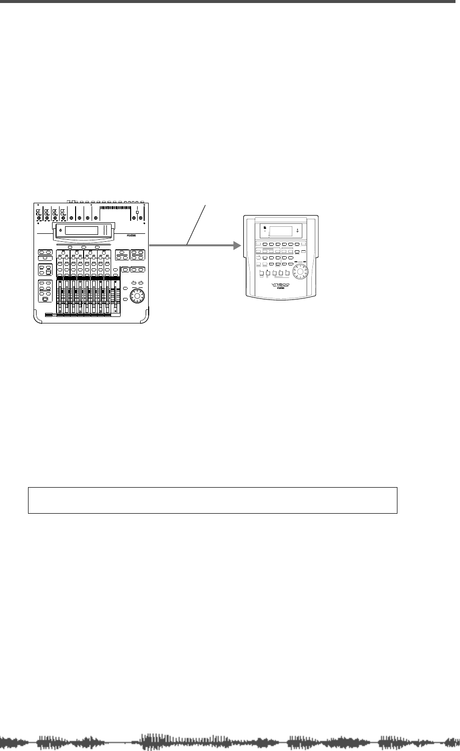
Digital Connections
166
VM200 User’s Guide
Using ADAT OUT
You can use an optical cable to connect the ADAT OUT connector on
the VM200 to an ADAT-compatible recorder, such as the Fostex
VR800 digital multitrack recorder.
The ADAT OUT connector outputs the same information as the REC
BUSS, but in digital form. The left channel of the REC BUSS stereo
signal is output to tracks 1, 3, 5, and 7, and the right channel to
tracks 2, 4, 6, and 8.
You can send channel 1–8 signals to ADAT DIRECT using the
ROUTING
function page. The channel 1 signal is output to ADAT track 1, the
channel 2 signal is output to ADAT track 2, etc.
In this configuration, the VM200 is the word clock master and the
multitrack recorder or ADAT is the slave.
Set the Word Clock parameter on the VM200 to “INT44.”
For more information on the master word clock setup, refer to “Set-
ting the Master Word Clock” on page 162.
To route a digital signal to ADAT OUT, follow the steps below:
Assigning Channels to ADAT DIRECT SENDs
1.
Press the Page Select
[1–8 ANALOG IN]
key to select the 1–8
channel layer.
The
[1–8 ANALOG IN]
key lights up.
2.
Press the
[ROUTING/PHASE]
key.
The VM200 displays the
1: ROUTING
function page. The
[ROUT-
ING/PHASE]
key and selectable
[EQ EDIT]
keys flash; selected
[EQ
EDIT]
keys light up.
The
ROUTING
function page features a 3-by-20 matrix. The top row
of the matrix, labelled “DIRECT,” indicates which channels have
been sent to the ADAT OUT.
Note:
The VM200 is unable to route signals from channels 9–16 (ADAT
IN) and channels 17–20 (EFF TN) to the ADAT DIRECT SEND.
ADAT OUT
DATA IN
.
VR800
optical cable
INPUT 4INPUT 3INPUT 2INPUT 1
PAD
26dB
A
B
PAD
26dB
A
B
PAD
26dB
A
B
PAD
26dB
A
B
-16 -60
+10 -34
-16 -60
+10 -34
-16 -60 -16 -60
TRIMTRIMTRIMTRIM
DIGITAL RECORDING MIXER
VM200
SCENE MEMORYREC BUSS
EFF EDITSELECTED EQ
EQ/HI
EQ/HI-MIDEQ/LO-MIDEQ/LOSETUP
CURRENT SCENE STATUS
KEY MODE
+10
0
-10
-20
-30
-40
-
+10
0
-10
-20
-30
-40
-
+10
0
-10
-20
-30
-40
-
+10
0
-10
-20
-30
-40
-
+10
0
-10
-20
-30
-40
-
+10
0
-10
-20
-30
-40
-
+10
0
-10
-20
-30
-40
-
16
8
GAIN
FREQ
PAN
Q
PAN
ON ON ON ON ON ON ON
SOLO SOLO SOLO SOLO SOLO SOLO SOLO
EQ EDIT EQ EDIT EQ EDIT EQ EDIT EQ EDIT EQ EDIT EQ EDIT EQ EDIT
SOLO
ON ON
SOLO
EQ LIBRARY
STORERECALL
EQ ON
EFF LIBRARY
STORERECALL
EFF2EFF1
STORERECALLSOLO
+1/ /-1
DATA
EXIT
ENTER
MASTER
15
7
14
6
13
5
12
4
11
3
10
2
9
1
2019
18
17
FREQ QFREQ Q
FREQ Q
GAINGAINGAIN
1-8 ANALOG IN 9-16 ADAT IN 17-20 EFF RTN
PAGE SELECT
SYSTEM MIDI
PHASE GROUP
ROUTING/ PAIR/
CH VIEW METER
CHANNEL/
AUX1
FADER MODE
AUX2
AUX3 AUX4
EFF1 EFF2
CHANNEL
ADD.AUX
TRIM
-10 -50
TRIM TRIM TRIM
-10 -50 -10 -50 -10 -50
INPUT 5 INPUT 6 INPUT 7 INPUT 8
MIN MAX
GAIN
MAXMIN
GAIN
2TRK IN
PHONESMONITOR
+10
0
-10
-20
-30
-40
-
EFF RTN
ADAT IN
ANALOG IN
0
-10
-20
-30
-60
-
-40
MMC SEND
PANPANPA NPA NPA NPAN
-48
-36
-24
-18
-12
-9
-6
-3
OL
ST BUSS/SOLO
LR
METER
+10 -34 +10 -34
SHIFT P.EDIT LOC MEM
RECORD STOP PLAY REW F FWD
AUTO PUNCH
CLIPBOARD
AUTO RTN
OUTIN
ENDOUTINSTART
EJECT
ACCESS
5678
OL
24
12
6
0
1234
RECORD TRACK
4321 5 678
EXECUTE
/ YES
EXIT
/ NO
DISP SEL
UNDO / REDO
EDITHOLD/ STORE SETUP
JOG
VARI PITCH SCRUBLOCATEAUTO PLAY
PGM SEL
AUTO RTN TIME BASE SEL SHUTTLE
LOCATE REC END
LOCATE ABS 0
CLIPBOARD PLAY
PUNCH
AUTO
OPTICAL
A SYNC
PREVIEW
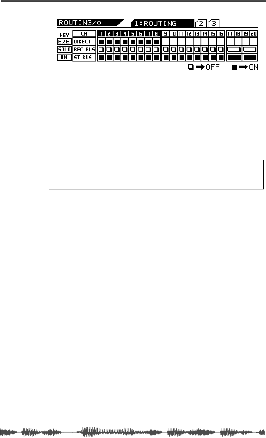
Assigning Channels to ADAT DIRECT SENDs
VM200 User’s Guide
167
3.
Use the
[EQ EDIT]
keys to turn on the channels you wish to
send to the ADAT OUT.
Selected
[EQ EDIT]
keys light up. On the display, the “DIRECT”
indicators highlight (darken).
In the example above, channels 1–8 are sent directly to the corre-
sponding ADAT channels.
4.
Press the
[CHANNEL/METER]
key.
The VM200 displays the
CHANNEL EDIT
function page.
Note:
The Rec Buss also sends the left signal to channels 1, 3, 5 and
7, and the right signal to channels 2, 4, 6 and 8 so that you can route
them to ADAT OUT 1–8 directly. This configuration enables you to send
two mixes to two different external recorders at the same time.
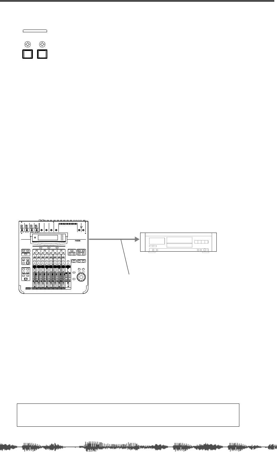
Digital Connections
168
VM200 User’s Guide
S/P DIF IN/OUT
The VM200 features S/P DIF digital in and out connectors on the rear
panel.
“S/PDIF” is an abbreviation for the Sony/Philips Digital InterFace, a
digital format that enables two channels of digital audio to flow
through an RCA connector (coaxial) or an optical cable. The VM200
requires an optical S/P DIF connection.
Using S/P DIF OUT
The VM200 outputs the ST BUSS signal in digital S/P DIF format
from the S/P DIF Out optical connector on the rear panel.
You can connect this output to any digital device that features an
S/P DIF Optical input, such as a DAT recorder or MiniDisc recorder
to mixdown in stereo.
You can also connect the S/P DIF out to the S/P DIF IN of another
VM200 in a cascade configuration. See “Cascading the VM200” on
page 171 for more information.
In this example, the VM200 S/P DIF output is connected to the digital
input of a DAT recorder for digital mixdown recording.
The VM200 serves as the word clock master; the DAT is a word clock
slave. Set the “Master Word Clock” parameter on the V200 to “INT44.”
Refer to “Setting the Master Word Clock” on page 162 for more infor-
mation.
If you select the digital input on the DAT recorder as the recording
source, the DAT should automatically synchronize to the word clock
signal from the VM200. On some DAT recorders, you may need to
specify the word clock source. Refer to the instructions supplied with
your DAT recorder.
Note:
If the connected digital device has only the COAXIAL (RCA pin)
jack as a digital input, use a Fostex COP-1 (an optical-to-coaxial con-
verter).
OUTIN
S/P DIF
S/P DIF OUT
DIGITAL IN
.
optical cable
DAT
INPUT 4INPUT 3INPUT 2INPUT 1
PAD
26dB
A
B
PAD
26dB
A
B
PAD
26dB
A
B
PAD
26dB
A
B
-16 -60
+10 -34
-16 -60
+10 -34
-16 -60 -16 -60
TRIMTRIMTRIMTRIM
DIGITAL RECORDING MIXER
VM200
SCENE MEMORYREC BUSS
EFF EDITSELECTED EQ
EQ/HI
EQ/HI-MIDEQ/LO-MIDEQ/LOSETUP
CURRENT SCENE STATUS
KEY MODE
+10
0
-10
-20
-30
-40
-
+10
0
-10
-20
-30
-40
-
+10
0
-10
-20
-30
-40
-
+10
0
-10
-20
-30
-40
-
+10
0
-10
-20
-30
-40
-
+10
0
-10
-20
-30
-40
-
+10
0
-10
-20
-30
-40
-
16
8
GAIN
FREQ
PAN
Q
PAN
ON ON ON ON ON ON ON
SOLO SOLO SOLO SOLO SOLO SOLO SOLO
EQ EDIT EQ EDIT EQ EDIT EQ EDIT EQ EDIT EQ EDIT EQ EDIT EQ EDIT
SOLO
ON ON
SOLO
EQ LIBRARY
STORERECALL
EQ ON
EFF LIBRARY
STORERECALL
EFF2EFF1
STORERECALLSOLO
+1/ /-1
DATA
EXIT
ENTER
MASTER
15
7
14
6
13
5
12
4
11
3
10
2
9
1
2019
18
17
FREQ QFREQ Q
FREQ Q
GAINGAINGAIN
1-8 ANALOG IN 9-16 ADAT IN 17-20 EFF RTN
PAGE SELECT
SYSTEM MIDI
PHASE GROUP
ROUTING/ PAIR/
CH VIEW METER
CHANNEL/
AUX1
FADER MODE
AUX2
AUX3 AUX4
EFF1 EFF2
CHANNEL
ADD.AUX
TRIM
-10 -50
TRIM TRIM TRIM
-10 -50 -10 -50 -10 -50
INPUT 5 INPUT 6 INPUT 7 INPUT 8
MIN MAX
GAIN
MAXMIN
GAIN
2TRK IN
PHONESMONITOR
+10
0
-10
-20
-30
-40
-
EFF RTN
ADAT IN
ANALOG IN
0
-10
-20
-30
-60
-
-40
MMC SEND
PANPANPA NPA NPA NPAN
-48
-36
-24
-18
-12
-9
-6
-3
OL
ST BUSS/SOLO
LR
METER
+10 -34 +10 -34
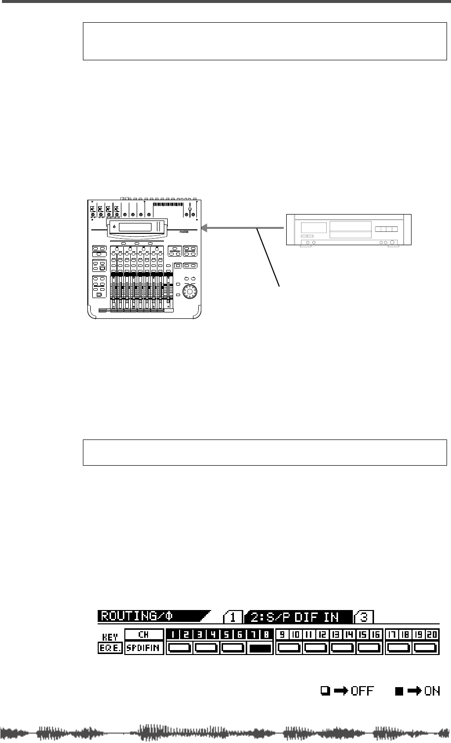
Using S/P DIF IN
VM200 User’s Guide
169
Using S/P DIF IN
You can connect the S/P DIF output from a CD player, DAT, or Mini-
Disc player to the S/P DIF IN optical connector on the rear panel of
the VM200.
You can also connect the S/P DIF output from
a second
VM200 to the
S/P DIF IN optical connector in a cascade configuration. See “Cascad-
ing the VM200” on page 171 for more information.
In this connection example, a DAT machine is connected to the S/P
DIF OUT connector on the rear panel of the VM200 to enable mixing
from a digital source.
The DAT machine serves as word clock master, and the VM200 is
word clock slave. You need to set the Master Word Clock setting to
“S/P DIF44” or “S/P DIF48” depending on the sample frequency of the
source. For more information on the master word clock setup, refer to
“Setting the Master Word Clock” on page 162.
Assigning S/P DIF Signals to Channels
Follow these steps to assign a two-channel digital stereo signal (input
via S/P DIF IN) to specific channels:
1.
Press the
[ROUTING/PHASE]
key twice.
The
[ROUTING/PHASE]
key and selectable
[EQ EDIT]
keys flash, and
the VM200 displays the
2:S/P DIF IN
function page.
Note:
Make sure that signals are routed to ST Buss so that they are
also output to the S/P DIF OUT. (See “Routing Input Channels” on
page 66 for more information.)
Note:
If the connected digital device has only the COAXIAL (RCA pin)
jack as a digital output, use a Fostex COP-1 optical-to-coaxial converter.
S/P DIF IN
DIGITAL OUT
.
optical cable
DAT
INPUT 4INPUT 3INPUT 2INPUT 1
PAD
26dB
A
B
PAD
26dB
A
B
PAD
26dB
A
B
PAD
26dB
A
B
-16 -60
+10 -34
-16 -60
+10 -34
-16 -60 -16 -60
TRIMTRIMTRIMTRIM
DIGITAL RECORDING MIXER
VM200
SCENE MEMORYREC BUSS
EFF EDITSELECTED EQ
EQ/HI
EQ/HI-MIDEQ/LO-MIDEQ/LOSETUP
CURRENT SCENE STATUS
KEY MODE
+10
0
-10
-20
-30
-40
-
+10
0
-10
-20
-30
-40
-
+10
0
-10
-20
-30
-40
-
+10
0
-10
-20
-30
-40
-
+10
0
-10
-20
-30
-40
-
+10
0
-10
-20
-30
-40
-
+10
0
-10
-20
-30
-40
-
16
8
GAIN
FREQ
PAN
Q
PAN
ON ON ON ON ON ON ON
SOLO SOLO SOLO SOLO SOLO SOLO SOLO
EQ EDIT EQ EDIT EQ EDIT EQ EDIT EQ EDIT EQ EDIT EQ EDIT EQ EDIT
SOLO
ON ON
SOLO
EQ LIBRARY
STORERECALL
EQ ON
EFF LIBRARY
STORERECALL
EFF2EFF1
STORERECALLSOLO
+1/ /-1
DATA
EXIT
ENTER
MASTER
15
7
14
6
13
5
12
4
11
3
10
2
9
1
2019
18
17
FREQ QFREQ Q
FREQ Q
GAINGAINGAIN
1-8 ANALOG IN 9-16 ADAT IN 17-20 EFF RTN
PAGE SELECT
SYSTEM MIDI
PHASE GROUP
ROUTING/ PAIR/
CH VIEW METER
CHANNEL/
AUX1
FADER MODE
AUX2
AUX3 AUX4
EFF1 EFF2
CHANNEL
ADD.AUX
TRIM
-10 -50
TRIM TRIM TRIM
-10 -50 -10 -50 -10 -50
INPUT 5 INPUT 6 INPUT 7 INPUT 8
MIN MAX
GAIN
MAXMIN
GAIN
2TRK IN
PHONESMONITOR
+10
0
-10
-20
-30
-40
-
EFF RTN
ADAT IN
ANALOG IN
0
-10
-20
-30
-60
-
-40
MMC SEND
PANPANPA NPA NPA NPAN
-48
-36
-24
-18
-12
-9
-6
-3
OL
ST BUSS/SOLO
LR
METER
+10 -34 +10 -34

Digital Connections
170
VM200 User’s Guide
2.
Press the
[EQ EDIT]
keys for channels to which you wish to
send the S/P DIF signal.
You can assign multiple channels.
On the display, the indicators for the assigned channel pairs
highlight (darken), and their
[EQ EDIT]
keys light up in paired uni-
son.
In the example above, channels 7–8 are assigned to receive the
S/P DIF signal.
3.
Press the
[CHANNEL/METER]
key or
[EXIT]
key.
The VM200 displays the
CHANNEL EDIT
function page.
Note:
Since S/P DIF carries a two-channel signal, you must always set
the channels in pairs. For example, if you select channel 1 to assign S/P
DIF signal, channel 2 will be also selected and paired. You do not need
to pair the channels using the Pairing function in this case.
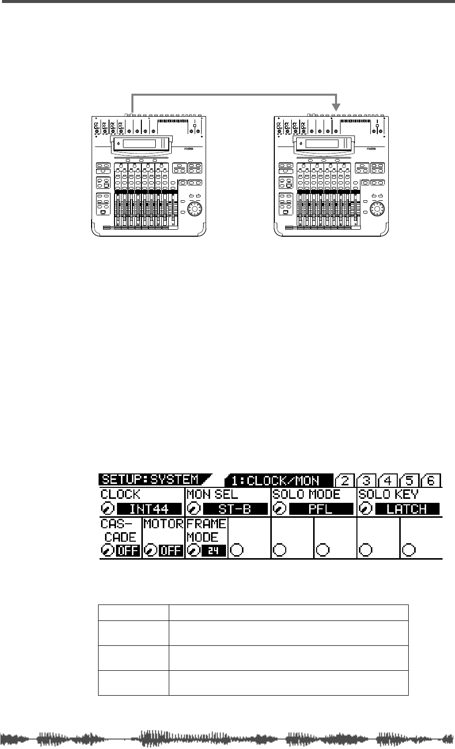
Cascading the VM200
VM200 User’s Guide
171
Cascading the VM200
You can connect up to three VM200s together in a cascade configu-
ration to enable 36-plus channels of digital mixing. A two-mixer cas-
cade is illustrated below.
In this figure, the stereo buss signal flows from the VM200-A S/P DIF
OUT to the VM200-B S/P DIF IN. (S/P DIF OUT outputs the stereo
buss signal in digital form.)
VM200-A serves as word clock master. Its Clock parameter is set to
INT44.
(You can access the Clock parameter by pressing the
[SYSTEM]
key to
display the
1:CLOCK/MON
function page as shown below.)
The other VM200 serves as word clock slave. Its Clock parameters is
set to SPDIF44. Refer to “Setting the Master Word Clock” on page 162
for more information on word clock.
To configure multiple VM200s in a cascade, follow these steps:
1.
Press the
[SYSTEM]
key.
The VM200 displays the Setup:System
1:CLOCK/MON
function page.
2.
Rotate the EQ/LO Freq rotary control to select one of the fol-
lowing options:
3.
Press the [EXIT] key or [CHANNEL/METER] key.
OFF This is the default setting. The VM200s will not cascade.
ON-A The Cascade function is turned on. Channels 7 and 8 are
disabled.
ON-B The Cascade function is turned on. Channels 15 and 16
are disabled.
ON-C The Cascade function is turned on. Channels 19 and 20
are disabled.
INPUT 4INPUT 3INPUT 2INPUT 1
PAD
26dB
A
B
PAD
26dB
A
B
PAD
26dB
A
B
PAD
26dB
A
B
-16 -60
+10 -34
-16 -60
+10 -34
-16 -60 -16 -60
TRIMTRIMTRIMTRIM
DIGITAL RECORDING MIXER
VM200
SCENE MEMORYREC BUSS
EFF EDITSELECTED EQ
EQ/HI
EQ/HI-MIDEQ/LO-MIDEQ/LOSETUP
CURRENT SCENE STATUS
KEY MODE
+10
0
-10
-20
-30
-40
-
+10
0
-10
-20
-30
-40
-
+10
0
-10
-20
-30
-40
-
+10
0
-10
-20
-30
-40
-
+10
0
-10
-20
-30
-40
-
+10
0
-10
-20
-30
-40
-
+10
0
-10
-20
-30
-40
-
16
8
GAIN
FREQ
PAN
Q
PAN
ON ON ON ON ON ON ON
SOLO SOLO SOLO SOLO SOLO SOLO SOLO
EQ EDIT EQ EDIT EQ EDIT EQ EDIT EQ EDIT EQ EDIT EQ EDIT EQ EDIT
SOLO
ON ON
SOLO
EQ LIBRARY
STORERECALL
EQ ON
EFF LIBRARY
STORERECALL
EFF2EFF1
STORERECALLSOLO
+1/ /-1
DATA
EXIT
ENTER
MASTER
15
7
14
6
13
5
12
4
11
3
10
2
9
1
2019
18
17
FREQ QFREQ Q
FREQ Q
GAINGAINGAIN
1-8 ANALOG IN 9-16 ADAT IN 17-20 EFF RTN
PAGE SELECT
SYSTEM MIDI
PHASE GROUP
ROUTING/ PAIR/
CH VIEW METER
CHANNEL/
AUX1
FADER MODE
AUX2
AUX3 AUX4
EFF1 EFF2
CHANNEL
ADD.AUX
TRIM
-10 -50
TRIM TRIM TRIM
-10 -50 -10 -50 -10 -50
INPUT 5 INPUT 6 INPUT 7 INPUT 8
MIN MAX
GAIN
MAXMIN
GAIN
2TRK IN
PHONESMONITOR
+10
0
-10
-20
-30
-40
-
EFF RTN
ADAT IN
ANALOG IN
0
-10
-20
-30
-60
-
-40
MMC SEND
PANPANPA NPA NPA NPAN
-48
-36
-24
-18
-12
-9
-6
-3
OL
ST BUSS/SOLO
LR
METER
+10 -34 +10 -34
VM200-A VM200-B
S/P DIF OUT S/P DIF IN

Digital Connections
172 VM200 User’s Guide
The VM200 exits Setup mode and displays the CHANNEL EDIT func-
tion page.
Note: When you attempt to cascade multiple VM200s, be certain not
to assign S/P DIF IN to any channels, or the cascade operation will fail.
(You can check assignments by pressing the [ROUTING/PHASE] key
twice to display the S/P DIF IN function page.) Refer to “Assigning S/P
DIF Signals to Channels” on page 169.

DIGITAL RECORDING MIXER
VM200
REC BUSS
EFF EDITSELECTED EQ
EQ/HI
EQ/HI-MIDEQ/LO-MID
+10
0
-10
-20
-30
-40
-
+10
0
-10
-20
-30
-40
-
+10
0
-10
-20
-30
-40
-
+10
0
-10
-20
-30
-40
-
+10
0
-10
-20
-30
-40
-
+10
0
-10
-20
-30
-40
-
+10
0
-10
-20
-30
-40
-
GAIN
FREQ
PAN
Q
PAN
ON ON ON ON ON ON ON
SOLO SOLO SOLO SOLO SOLO SOLO SOLO
EQ EDIT EQ EDIT EQ EDIT EQ EDIT EQ EDIT EQ EDIT EQ EDIT EQ EDIT
SOLO
ON ON
SOLO
EQ LIBRARY
STORERECALL
EQ ON
EFF LIBRARY
STORERECALL
EFF2EFF1
RECALLSOLO
EXIT
14
6
13
5
12
4
11
3
2019
FREQ QFREQ Q
Q
GAINGAIN
9-16 ADAT IN 17-20 EFF RTN
P
AGE SELECT
GROUP
PAIR/
METER
CHANNEL/
MIN MAX
+10
0
1
0
1
0
0
-10
-20
-30
-60
-
-40
MMC SEND
PANPANPANPANPANPAN
-40
-36
-24
-18
1212
ST BUSS/SOLO
L R
VM200 User’s Guide
173
CHAPTER 11
VM200 & MIDI
About This Chapter
MIDI is an acronym for Musical Instrument Digital Interface, which
is an international technology standard that facilitates the
exchange of musical data between digital devices.
This chapter explains the MIDI-related capabilities of the VM200,
including its MIDI ports and parameters, as well as MIDI Machine
Control (MMC). This chapter also features several illustrations of
various system configurations involving MIDI.
Chapter Contents
Using the VM200 with MIDI . . . . . . . . . . . . . . . . . . . . . . . 174
MIDI Ports . . . . . . . . . . . . . . . . . . . . . . . . . . . . . . . . . . . . 174
MIDI Transmit and Receive Channels . . . . . . . . . . . . . . . . 176
Using Program Change Messages to Recall Scenes . . . . . . 180
Using Control Change Messages. . . . . . . . . . . . . . . . . . . . 184
Controlling Parameters Using Fostex Exclusive Messages . 188
Bulk Dump . . . . . . . . . . . . . . . . . . . . . . . . . . . . . . . . . . . 189
MMC (MIDI Machine Control) Send. . . . . . . . . . . . . . . . . . 192
Frame Mode . . . . . . . . . . . . . . . . . . . . . . . . . . . . . . . . . . . 194
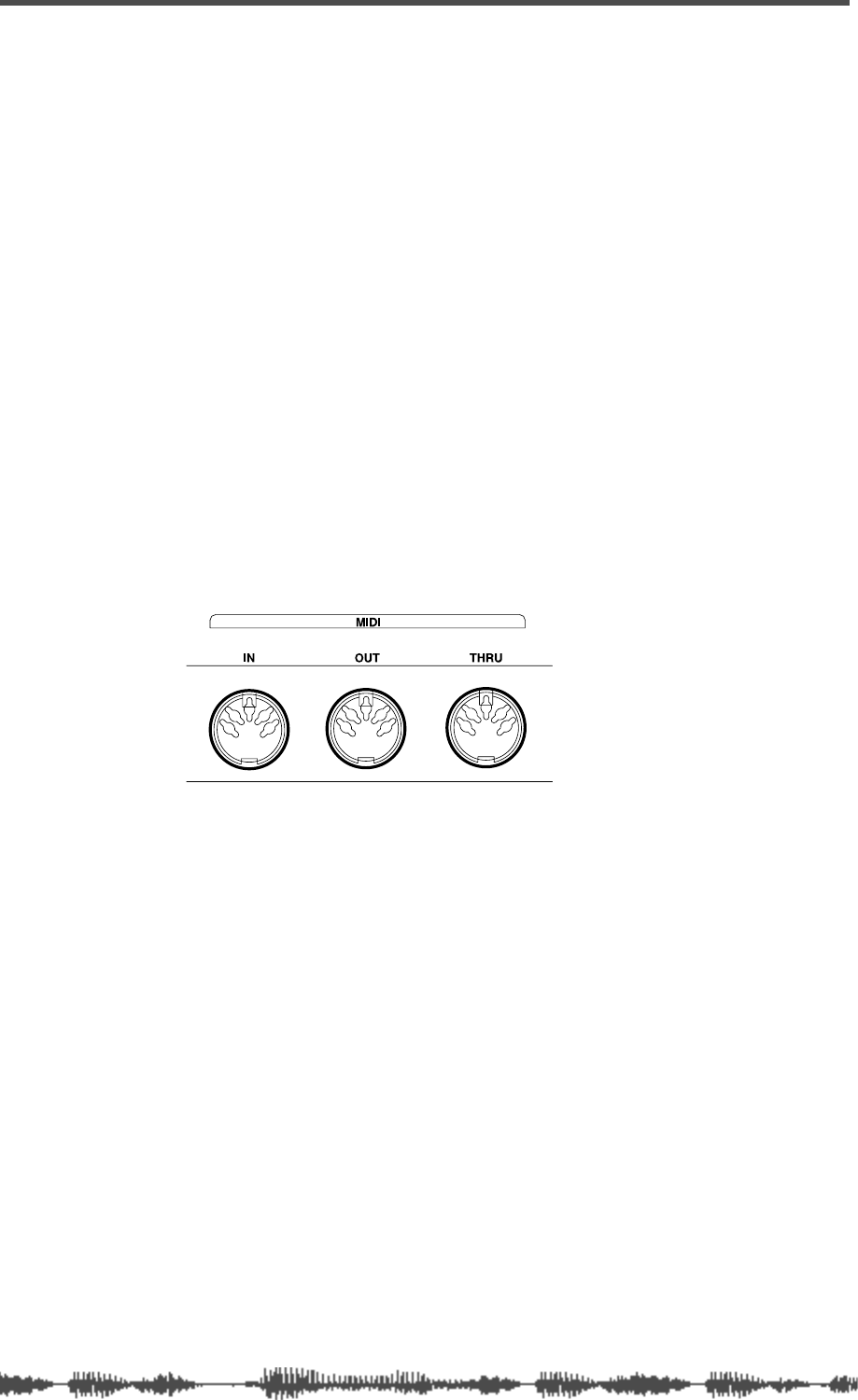
VM200 & MIDI
174
VM200 User’s Guide
Using the VM200 with MIDI
Using MIDI with the VM200 enables you to take fullest advantage of
all the VM200’s capabilities.
You can send MIDI Program Change messages to recall scenes from
Scene Memory, or send MIDI Control Change messages to enable
real-time parameter control. Fostex System Exclusive messages sim-
ilarly enable additional parameter control.
To backup and transfer data between two VM200s, you can use Sys-
tem Exclusive Bulk Dump commands.
If a recorder is connected to the VM200, you can control it remotely
via MIDI Machine Control (MMC).
You can also cascade multiple VM200s via MIDI connections and
remotely operate the VM200 via MIDI Local Control.
MIDI Ports
The VM200 has standard MIDI IN, MIDI OUT, and MIDI THRU ports
on the rear panel.
The MIDI IN port receives MIDI messages.
The MIDI OUT port transmits MIDI messages.
The MIDI THRU ports transmits the exact same MIDI messages
received at the MIDI IN port.
In addition to various MIDI instruments and devices, you can connect
a personal computer to the MIDI ports using a MIDI interface.
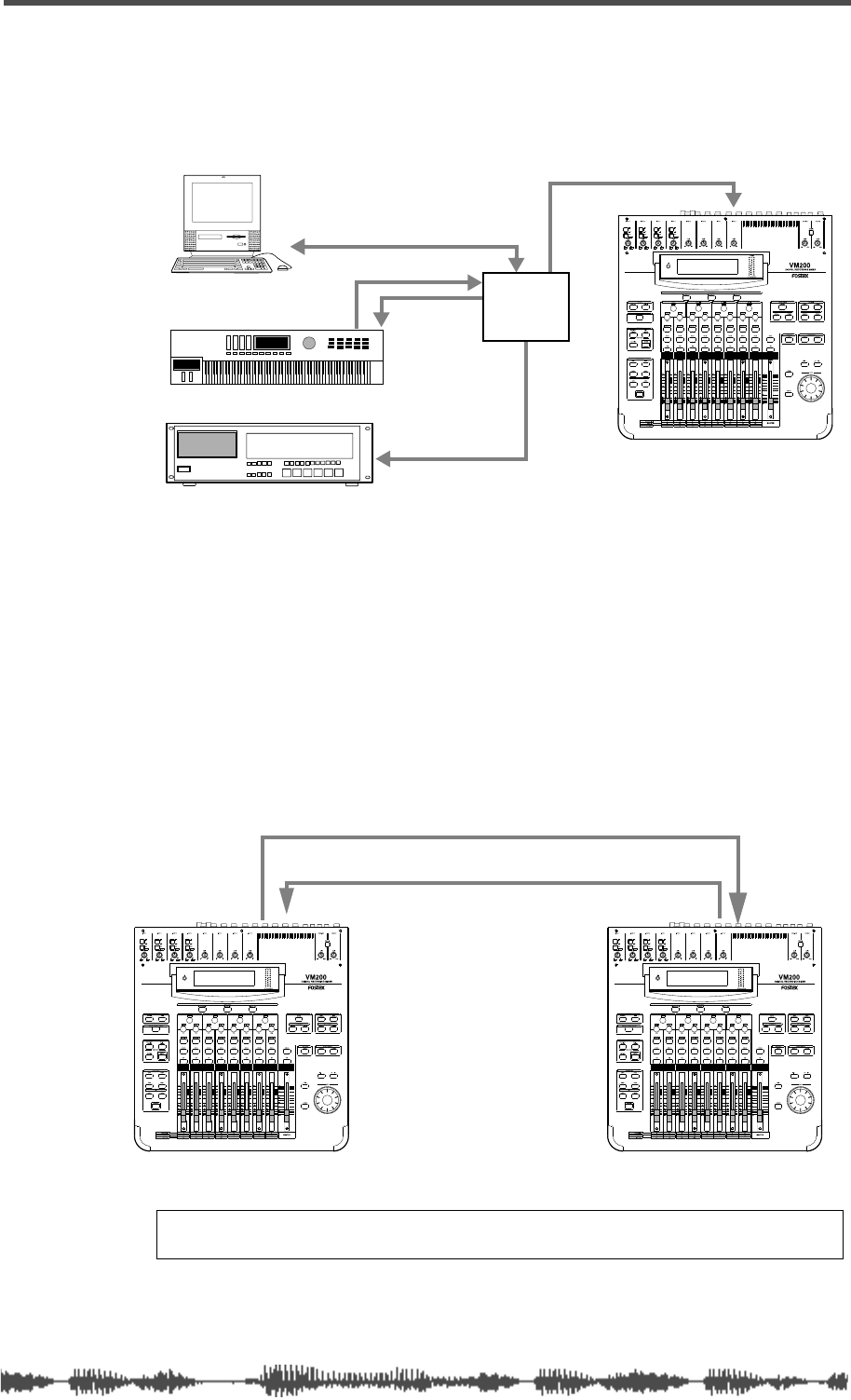
Connecting MIDI devices
VM200 User’s Guide
175
Connecting MIDI devices
The system illustrated below uses a standard MIDI interface to con-
nect the VM200, a MIDI keyboard, and a MIDI sampler to a com-
puter.
Cascading Two VM200s
In the configuration illustrated below, two VM200s are cascaded
(linked) together via MIDI. This type of connection enables you, for
example, to perform the following functions on both machines while
operating only one:
• Recall, store, and change the name of scene memories
• Update the display
• Control Solo mode
Note:
When you cascade two VM200s, be sure to set the ECHO param-
eter on
1: MIDI TX&RX
page to “OFF” to avoid message loop.
MIDI sampler
MIDI
VM200
serial port
MIDI IN
MIDI INMIDI OUT
MIDI IN
interface
MIDI sequencer
MIDI keyboard
MIDI OUT MIDI INMIDI OUT MIDI IN
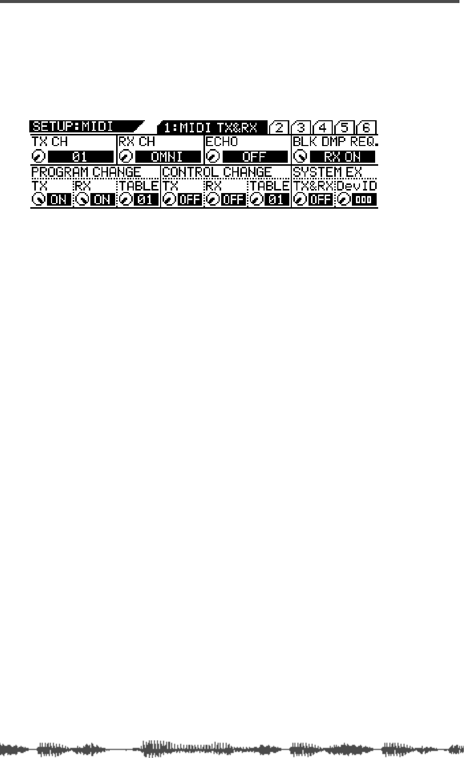
VM200 & MIDI
176
VM200 User’s Guide
MIDI Transmit and Receive Channels
This section explains the MIDI Transmit and Receive Channels.
Press the [MIDI] key to display the
1:MIDI TX&RX
function page. This
page enables you to set the transmit (TX) and Receive (RX) channels
for the VM200.
TX CH (Transmit Channel)
This parameter specifies the MIDI Transmit Channel. This is the
channel the VM200 will use to transmit MIDI messages. Select a
channel from 1 through 16.
Set the device that will receive MIDI messages from the VM200 to the
same MIDI Channel.
When the VM200 receives a request for MIDI data, it transmits a
response on the same MIDI channel that received the request.
The default setting is “1.”
RX CH (Receive Channel)
This parameter specifies the MIDI Receive Channel. This is the chan-
nel on which the VM200 will receive MIDI messages. Select a channel
from 1 through 16, or “Omni.”
Set the device that will transmit MIDI messages to the VM200 to the
same MIDI Channel.
If you select OMNI for the RX CH parameter, the target messages (Pro-
gram Change or Control Change) will be received on all channels.
The default setting is “Omni.”
ECHO
The ECHO parameter enables you to “echo” Program Change, Control
Change, or System Exclusive messages that are received by the
VM200 through to the MIDI OUT port, regardless of the MIDI Chan-
nel settings. The default setting is “Off.”

Program Change Messages
VM200 User’s Guide
177
Program Change Messages
You can send a Program Change message to the VM200 to recall a
scene from the VM200’s Scene Memory. (For more information, see
“Using Program Change Messages to Recall Scenes” on page 180.)
Inversely, by recalling a scene on the VM200, you can transmit Pro-
gram Change messages to connected MIDI devices or instruments.
Program Change TX
The Program Change TX parameter determines whether the VM200
will transmit Program Change messages when you recall a scene from
Scene Memory.
Turn the Program Change TX parameter on if you want to change pro-
grams on a connected synthesizer when you change scenes on the
VM200.
The default setting is “On.”
Program Change RX
The Program Change RX parameter determines whether the VM200
will recall a scene from Scene Memory when the VM200 receives a
Program Change message.
Turn the Program Change RX parameter on if you want to change
scenes on the VM200 from a connected sequencer.
The default setting is “On.”
Program Change Table
The Program Change Table assigns program change numbers to
scenes in Scene Memory.
These assignments enable you to send MIDI messages from an exter-
nal MIDI device to recall scenes on the VM200.
For example, you could assign Program Change Number 07 to Scene
07. If you then send Program Change Number 07 from a connected
sequencer to the VM200, the VM200 will recall Scene 07.
The VM200 features two Program Change Tables (01 User Table, and
02 Preset Table). You can use the Program Change Table parameter
to select Table 01 or 02.
The default setting is “01.”
For more information, refer to the “Program Change To Scene Memory
Assignment Tables” on page 210.

VM200 & MIDI
178
VM200 User’s Guide
Control Change Messages
You can send Control Change messages to the VM200 to control
VM200 parameters in real time. (For more information, see “Using
Control Change Messages” on page 184.)
Inversely, when you adjust parameters on the VM200, the VM200 can
transmit Control Change messages to remotely control the parame-
ters of connected MIDI devices or instruments.
Control Change TX
Turn on the Control Change TX parameter if you want the VM200 to
transmit Control Change messages when you adjust mix parameters.
The default setting is “Off.”
Control Change RX
Turn on the Control Change RX parameter if you want the VM200 to
adjust mix parameters when a Control Change message is received.
The default setting is “Off.”
Control Change Table
The Control Change Tables assign Control Change numbers to vari-
ous controller numbers.
These assignments enable you to send MIDI messages from an exter-
nal MIDI device to control VM200 parameters in real time.
For example, you could assign Control Change number 5 to channel
fader 5. If you then send Control Change number 5 from a connected
device to the VM200, the VM200 will adjust fader 5.
The VM200 features two Control Change Tables (01 User Table, and
02 Preset Table). You can use the Control Change Table parameter to
select Table 01 or 02.
The default setting is “01.”
For more information, refer to the “Control Change To Control
Parameters Assignment Tables” on page 211.

System Exclusive Messages (Fostex Exclusive)
VM200 UserÕs Guide
179
System Exclusive Messages (Fostex Exclusive)
You can control VM200 parameters in real time using System Exclu-
sive messages. For more information, see System Exclusive Parame-
ter Control on page 188.
If you want the VM200 to receive System Exclusive messages, turn on
the “System Exclusive TX & RX” parameter (described below).
The “DevID” (device ID) should match the number selected on the
external MIDI device.
System Exclusive TX & RX
This parameter determines whether or not the VM200 adjusts mix
parameters when System Exclusive messages are received, or
whether the VM200 transmits parameter settings in response to
Parameter Requests.
It also determines whether the VM200 transmits System Exclusive
messages on the “DevID” channel when mix parameters are adjusted,
or whether the VM200 transmits Parameter Requests on the “DevID”
channel.
You can set this parameter to “On” or “Off.” The default setting is
“Off.”
System Exclusive DevID
This parameter determines the ID number of the device to and from
which the VM200 transmits and receives System Exclusive messages.
You can set this parameter to 0 – 126. The default setting is “0.”
Bulk Dump
You can use the System Exclusive Bulk Dump to transfer VM200 data
(such as Scene Memory, EQ Library, Effects Library, and Setup data)
to another MIDI device.
This is useful for backing-up VM200 data to a MIDI data filer or com-
puter, or for exchanging data between VM200s.
Bulk RX
The Bulk RX parameter determines whether the VM200 receives MIDI
Bulk requests and MIDI Bulk Dump messages.
If you turn on the Bulk RX parameter, the VM200 transmits Bulk
Dump messages in response to Bulk Dump requests.
Bulk Dump messages and Bulk Dump requests are not echoed.
You can transmit Bulk Dump messages from the VM200 regardless of
this setting.
See “Bulk Dump” on page 189 for more information.
Note:
Fostex does not guarantee compatibility of MIDI Bulk Dump mes-
sages between two VM200s with different software versions.

VM200 & MIDI
180
VM200 User’s Guide
Using Program Change Messages to Recall Scenes
When the VM200 receives a MIDI Program Change, it can recall a
scene from Scene Memory. (Which scene it recalls is determined by
the Program Change Assignment Table. For more information, see
page 210.)
Similarly, when you recall a scene on the VM200, it can transmit a
Program Change message that will recall a scene on another VM200.
Alternatively, the Program Change message can be recorded to a
MIDI sequencer and later used to recall a particular scene automati-
cally.
Scene Memories 0 through 99 and Preset Scenes P0, P1, and P2 are
initially assigned to Program Changes 1 through 128. However, you
can edit these assignments using the
3:PGM. TABLE2
function page,
which you can access by pressing the
[MIDI]
function key.
These assignments control both transmission (TX) and reception
(RX). For example, when the VM200 receives Program Change 07
from an external MIDI device, it will recall Scene 07. Inversely, when
Scene 07 is recalled, the VM200 will transmit Program Change 07.
Follow these steps to set up the VM200 to receive and transmit MIDI
Program Change messages:
1.
Press the
[MIDI]
key.
The VM200 displays the
1:MIDI TX&RX
function page.
2.
Set the VM200 and the external MIDI device to the same
MIDI channel.
The external MIDI device that receives MIDI messages from the
VM200 should be set to the MIDI Channel specified by the TX CH
parameter.
The RX CH parameter of the VM200 should be set to the same
MIDI Channel as the device transmitting MIDI messages.
3.
Set the TX CH and/or RX CH parameters to ON.
Use the EQ/LO and EQ/LO-MID Gain rotary controls. Refer to
the illustration below.
Program Change TX and RX are “ON.”
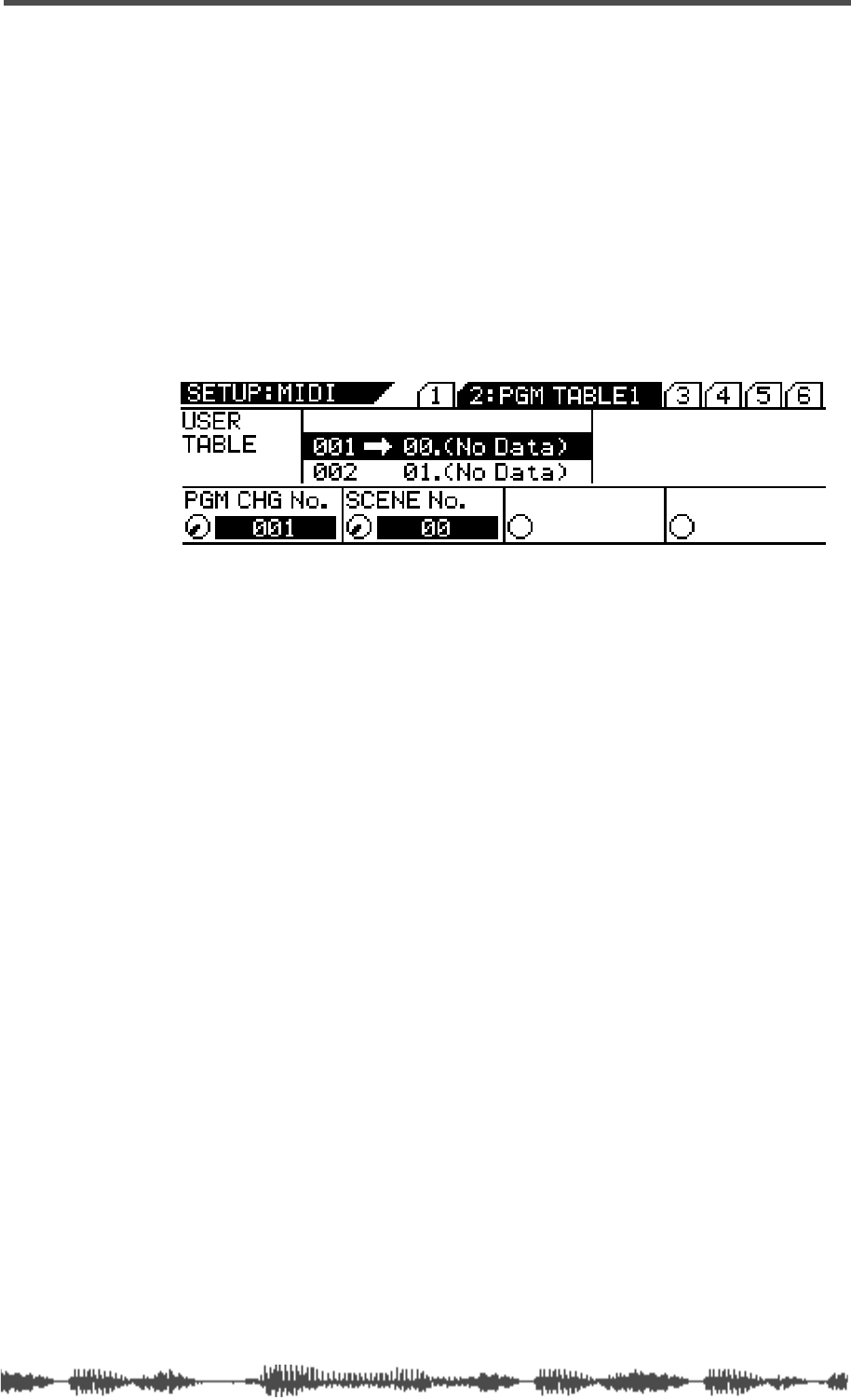
Editing the User Program Change Assign Table
VM200 User’s Guide
181
Editing the User Program Change Assign Table
The VM200 features two Program Change Assign Tables.
The first is the User Table, which appears on the
2:PGM TABLE1
function
page. You can edit the assignments in this table.
The second table is the Preset Table, which appears on the
3:PGM
TABLE2
function page. You can view the assignments in the Preset
table, but not edit them.
Follow the steps below to assign a Scene Memory to a Program
Change number.
1.
Press the
[MIDI]
key twice.
The VM200 displays the
2:PGM TABLE1
function page.
2.
Select a Program Change number.
Rotate the EQ/LO GAIN
rotary control to select a number from 1
through 128.
As you turn the control, the PGM CHG No. parameter changes and
the Assign Table reflects the change.
3.
Select a Scene number.
Rotate the EQ/LO-MID GAIN rotary control to select a scene num-
ber from P0, P1, P2, or 00 through 99.
As you turn the control, the SCENE No. parameter changes, and
the Assign Table scrolls to reflect the change.
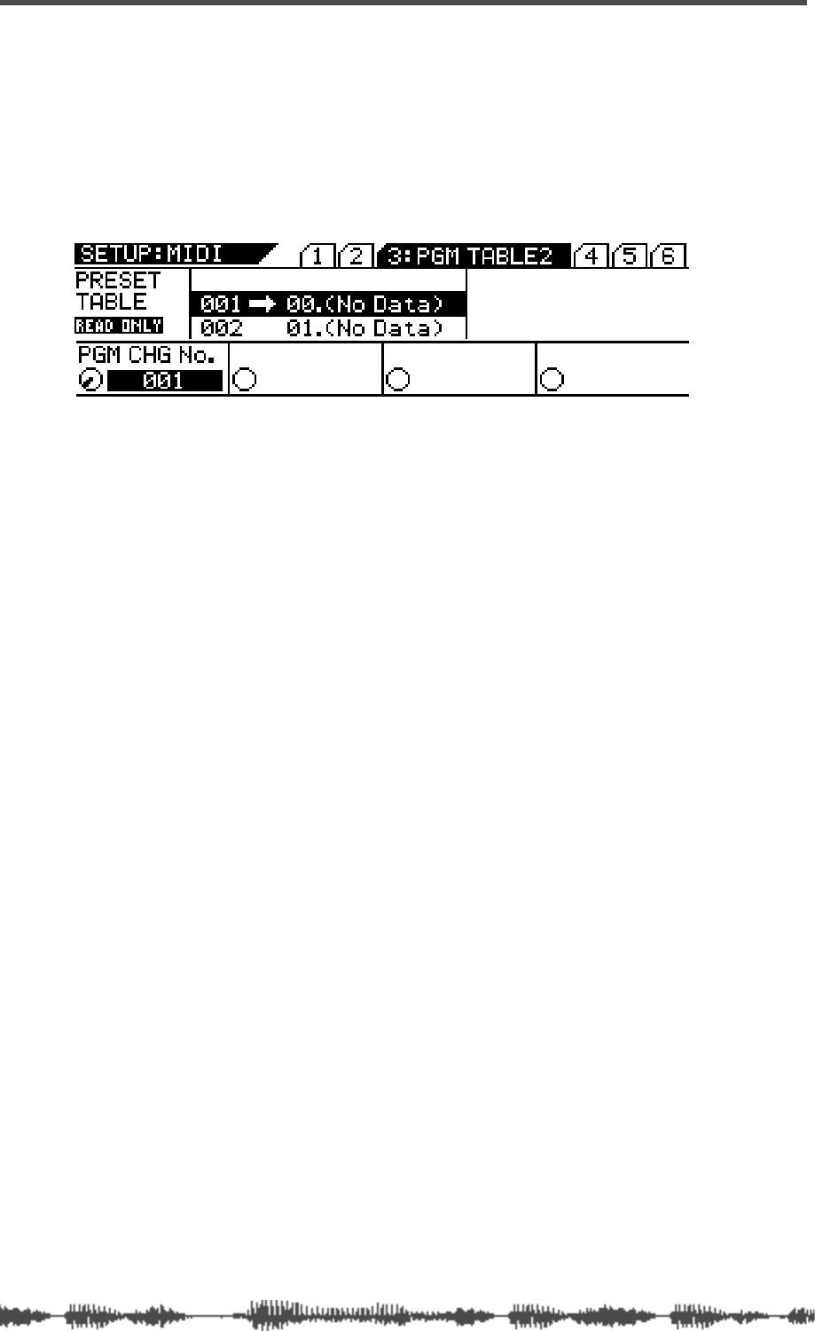
VM200 & MIDI
182
VM200 User’s Guide
Viewing the Preset Program Change Assign Table
The Preset Program Change Assign Table appears on the
3:PGM TABLE2
function page.
Follow these steps to view the Preset assignments:
1.
Press the
[MIDI]
key three times.
The VM200 displays the
3:PGM TABLE2
function page.
2.
Select a Program Change number.
Rotate the EQ/LO GAIN rotary control to select a number from
001 through 128.
As you turn the control, the PGM CHG No. parameter changes,
and the Assign Table scrolls to reflect the change.
The Scene number assigned to the selected Program Change
number will appear next to it in the Assign Table.
Program Change Assign Table Notes
The “Scene Memory to Program Change Assign Table” appears on
page 210.
To reset the assignments to their initial settings, press the
[SYSTEM]
key six times or until it displays the
6:INITIALIZE
function page. Turn
the EQ/LO GAIN rotary control to set the INIT ITEM parameter to
“PGM TBL,” and press the
[ENTER]
key. For more information, see
“Initializing the VM200” on page 197.
You can store the Program Change Assign Table to an external MIDI
device, such as a MIDI data filer, using MIDI Bulk Dump. (See “Bulk
Dump” on page 179 for more information.)
If a scene is assigned to two or more program changes, the lowest pro-
gram change is transmitted when the scene is recalled.
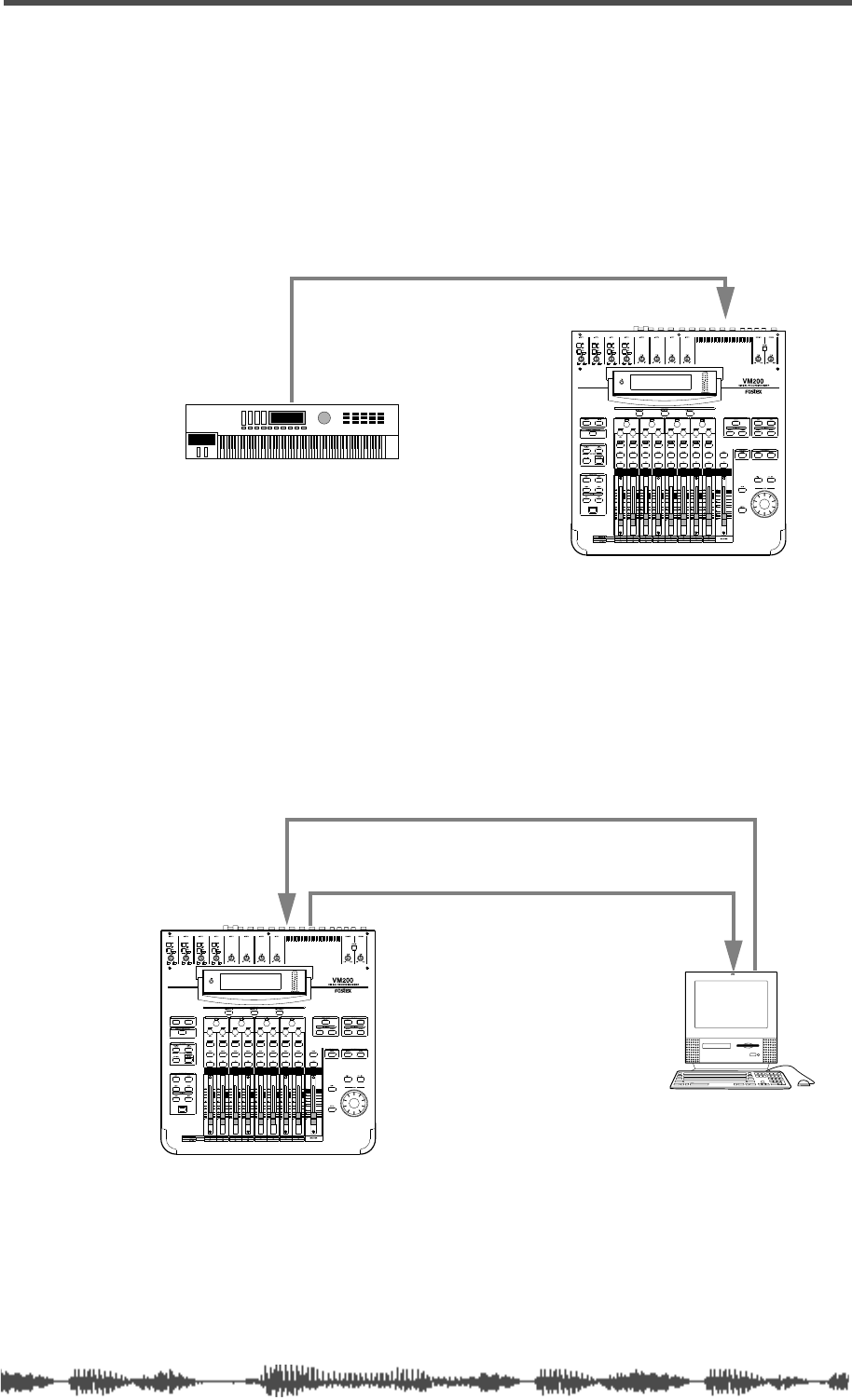
Examples: Using Program Change Messages
VM200 User’s Guide
183
Examples: Using Program Change Messages
The following figures illustrate typical ways in which to utilize MIDI
Program Change messages with the VM200.
In the following example, if you are using the Preset Program Change
Table (which appears on function page
3:PGM TABLE2
), when you send
Program Change 10 from the MIDI keyboard, the VM200 will recall
Scene 10, due to preset assignment.
In the following example, Program Change 33 has been programmed
into a song on the MIDI sequencer and will be transmitted to the
VM200 at the specified point when the song is played.
If you are using the Preset Program Change Table (2), the VM200 will
recall Scene 33, due to preset assignment.
Since the VM200 outputs Program Change messages when scenes are
recalled, you can record “scene recalls” to the MIDI sequencer in real
time.
You can also connect two VM200s via MIDI and recall a scene on the
first VM200, so that the corresponding Program Change message will
be transmitted to the second VM200 recall the assigned scene.
MIDI OUT
MIDI IN
MIDI keyboard
MIDI OUTMIDI IN
MIDI IN MIDI OUT
MIDI sequencer

VM200 & MIDI
184
VM200 User’s Guide
Using Control Change Messages
When the VM200 receives a MIDI Control Change message, it can
adjust a mix parameter specified by the Control Change Assign Table.
(For more information, see page 211.)
Similarly, when a mix parameter is adjusted on the VM200, the
VM200 can transmit a Control Change message to control another
VM200.
Alternatively, you can record Control Change messages to a MIDI
sequencer and use them later to automate parameter control.
You can assign up to 114 mix parameters to Control Changes 0
through 95 and 102 through 119. (Due to the MIDI standard, Control
Changes 96 through 101 are unavailable.)
The VM200 “Control Change To Control Parameters Assignment
Tables” on page 211 lists initial assignments. You can edit these
assignments using the
4:CTL TABLE1
function page.
Follow these steps to set up the VM200 to receive and transmit MIDI
Control Change messages:
1.
Press the
[MIDI]
key.
The VM200 displays the
1:MIDI TX&RX
function page.
2.
Set the VM200 and the external MIDI device to the same
MIDI channel.
The external MIDI device that receives MIDI messages from the
VM200 should be set to the MIDI Channel specified by the TX CH
parameter.
The RX CH parameter of the VM200 should be set to the same
MIDI Channel as the device transmitting MIDI messages.
3.
Set the TX CH and/or RX CH parameters to ON.
Use the EQ/LO and EQ/LO-MID GAIN rotary controls. Refer to
the illustration below.
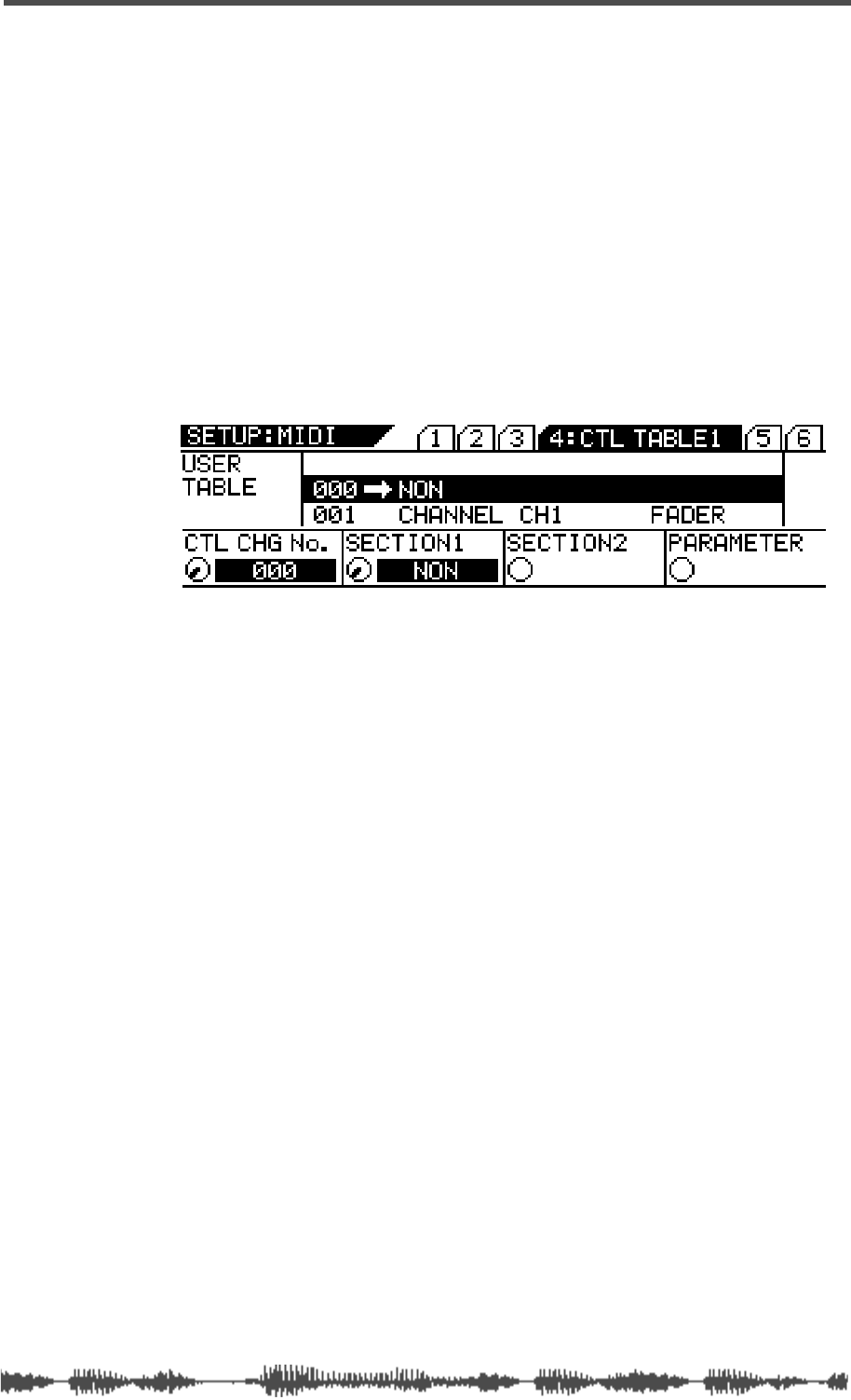
Editing the Control Change Assign Table
VM200 UserÕs Guide
185
Editing the Control Change Assign Table
The VM200 features two Control Change Assign Tables.
The first is the User Table, which appears on the
4:CTL TABLE1
function
page. You can edit the assignments in this table.
The second table is the Preset Table, which appears on the
5:CTL TABLE2
function page. You can view the assignments in the Preset table, but
not edit them.
Follow the steps below to assign a control parameter to a Control
Change number.
1.
Press the
[MIDI]
key four times.
The VM200 displays the
4:CTL TABLE1
function page.
The following page appears on the display.
2.
Select a Control Change number.
Rotate the EQ/LO GAIN rotary control to select a Control Change
number from 0 through 95 or 102 through 119. (Numbers 096
through 101 are unavailable).
3.
Select the section of the VM200 you wish to control with the
Control Change number.
Rotate the EQ/LO-MID GAIN rotary control to select the section
you wish to control with the selected Control Change number.
Options include NON, CHANNEL, MASTER, EFFECT, and SCENE
ST.
4.
Select the sub-section of the VM200 you wish to control.
Rotate the EQ/HI-MID GAIN rotary control to select a sub-section.
Options include CH1–20, ST BUSS, REC BUSS, AUX1–4, EFF1–2,
MODE, PST/PRE, and AUX PAIR. The available options vary
depending on your previous selections.
5.
Select a parameter item you wish to control with the selected
Control Change number.
Rotate the EQ/HI
[GAIN]
rotary control to select a parameter item.
The available options vary depending on your previous selections.
For more information, refer to the “Control Change To Control
Parameters Assignment Tables” on page 211.
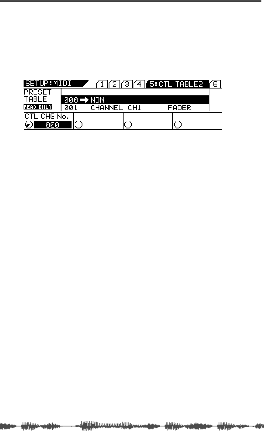
VM200 & MIDI
186
VM200 User’s Guide
Viewing the Preset Control Change Assign Table
The Preset Control Change Assign Table appears on the
5:CTL TABLE2
function page.
Follow these steps to view the Preset assignments:
1.
Press the [MIDI] key five times.
The VM200 displays the
5:CTL TABLE2
function page.
2.
Select a Control Change number.
Rotate the EQ/LO GAIN rotary control to select from 0 through 95
or 102–119.
As you turn the control, the CTL CHG No. parameter changes,
and the Assign Table scrolls to reflect the change.
The parameter item assigned to the selected Control Change
number will appear next to it in the Assign Table.
Control Change Assign Table Notes
The“Control Change To Control Parameters Assignment Tables” on
page 211.
To reset the assignments to their initial settings, press the
[SYSTEM]
key six times or until it displays the
6:INITIALIZE
function page. Turn
the EQ/LO GAIN rotary control to set the INIT ITEM parameter to
“CTL TBL,” and press the
[ENTER]
key. For more information, see “Ini-
tializing the VM200” on page 197.
You can store the Control Change Assign Table to an external MIDI
device, such as a MIDI data filer, using MIDI Bulk Dump. (See “Bulk
Dump” on page 179 for more information.)
If a parameter is assigned to two or more control changes, the lowest
control change is transmitted when the parameter is recalled.
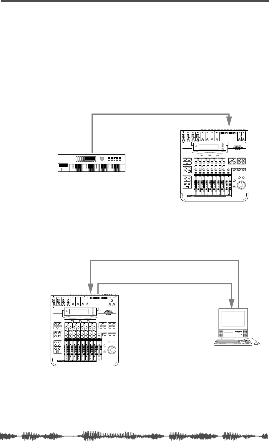
Examples: Using Control Change Messages
VM200 UserÕs Guide
187
Examples: Using Control Change Messages
The following figures illustrate typical ways in which to utilize MIDI
Control Change messages with the VM200.
The following example assumes you are using the Preset Control
Change Table (which appears on function page
5:CTL TABLE2
) and that
an assignable MIDI controller on the MIDI keyboard has been
assigned Control Change 83.
When you adjust the controller, Control Change 83 will be transmit-
ted to the VM200, which will then adjust the effect send 2 level for
input channel 2.
In the following example, input channel 5 fader movements are
recorded in real time to a MIDI sequencer using Control Change 5.
During playback, the sequencer transmits Control Change 5 back to
the VM200 and fader 5 moves accordingly, due to preset assignment.
You can also connect two VM200s via MIDI to enable you to control
the second VM200 from the first. For example, you could move the
Master Fader on the first VM200, causing the second VM200 to oper-
ate its Master Fader as well.
MIDI OUT
MIDI IN
MIDI keyboard
MIDI OUTMIDI IN
MIDI IN MIDI OUT
MIDI sequencer
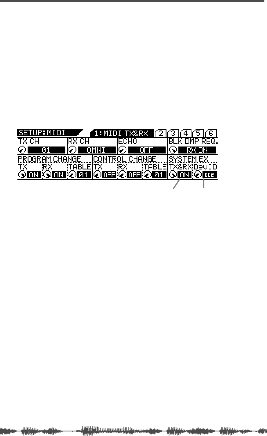
VM200 & MIDI
188
VM200 User’s Guide
Controlling Parameters Using Fostex Exclusive
Messages
You can also control VM200 parameters in real time using MIDI Sys-
tem Exclusive messages.
When you adjust a mix parameter, the VM200 transmits a System
Exclusive Parameter Change message.
To transmit and receive System Exclusive messages on the VM200,
set the SYSTEM EX. TX&RX parameter on the
1:MIDI TX&RX
function
page to “On” and set the DevID (Device ID) parameter to match the
device ID assigned to the external MIDI device.
Data formats for Fostex Exclusive messages are provided in the
Appendix.
System Exclusive TX&RX Device ID

Bulk Dump
VM200 UserÕs Guide
189
Bulk Dump
The VM200 can transfer Setup data, Scene Memories, Effect and EQ
Libraries, and Program and Control Change Assign Tables to another
MIDI device using the System Exclusive Bulk Dump function.
This function enables you to back up important VM200 data to a MIDI
data filer or computer, or to transfer data between multiple VM200s.
The VM200 can also receive Bulk Dump requests from other MIDI
devices.
Transmitting MIDI Bulk Dump Messages
The VM200 transmits Bulk Dump data on the transmission channel
you specify using the TX CH parameter on the
1:MIDI TX&RX
function
page.
To execute a Bulk Dump operation, you specify the data you wish to
transfer using the parameters on the
6:BULK DUMP
function page, then
press the
[ENTER]
key. The VM200 can also transmit data automati-
cally when it receives MIDI Bulk Dump Request.
The BLOCK parameter on the
6:BULK DUMP
function page enables you
to specify the block of data you wish to send.
Follow these steps to execute a Bulk Dump.
Automatic transmission in response to Bulk Dump Request
If you set the BLK DMP REQ. parameter on the
1:MIDI TX&RX
function
page to RX ON, the VM200 will be able to receive a MIDI Bulk Dump
request message from an external MIDI device.
1.
Press the
[MIDI]
key.
The VM200 displays the
1:MIDI TX&RX
function page.
2.
Rotate the EQ/HI GAIN rotary control to set the BLK DMP
REQ parameter to “RX ON.”
The default setting of the Bulk Dump Request parameter is “RX
ON.”
The VM200 will transmit Bulk Dump data on the specified MIDI
transmit channel when it receives Bulk Dump Request from the
connected MIDI device.
To specify which data you wish to transmit, see “Specifying the
data you want to transfer” on page 190.
Bulk Dump Request RX parameter
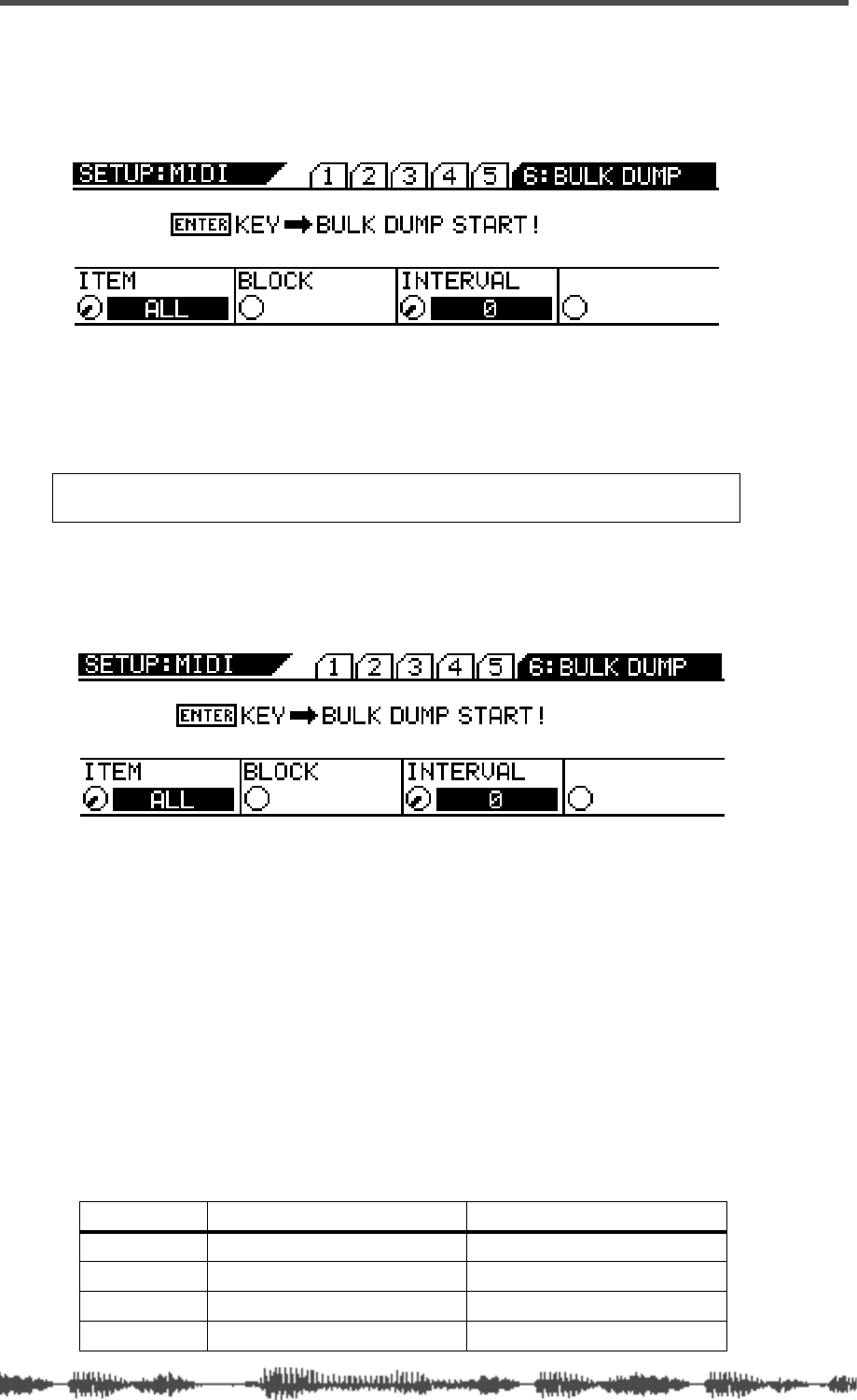
VM200 & MIDI
190 VM200 User’s Guide
Manual transmission of Bulk Dump Messages
1. Press the [MIDI] key six times (from start of cycle).
The VM200 displays the 6:BULK DUMP function page.
2. Press the [ENTER] key.
The VM200 starts transmitting Bulk Dump Data to the connected
MIDI device and displays the following message:
“WARNING! Transmit Bulk Dump Data Now...”
Specifying the data you want to transfer
1. Press the [MIDI] key six times (from start of cycle).
The VM200 displays the 6: BULK DUMP function page.
2. Rotate the EQ/LO GAIN rotary control to adjust the Item
parameter.
This parameter specifies the data you want the VM200 to trans-
fer.
3. Rotate the EQ/LO-MID GAIN rotary control to adjust the
Block parameter.
This parameter specifies the block of data you want the VM200 to
transfer. The Block parameter is available only if you select
SETUP, SCENE, EFF LIB, or EQ LIB for the Item parameter.
4. Rotate the EQ/HI-MID GAIN rotary control to adjust the
Interval parameter.
The Interval parameter specifies the interval between data blocks
during Bulk Dump transmission.
Warning: Do not power off the VM200 while it is transmitting data or
you may damage the system or the connected MIDI device.
Item Contents Block
ALL (default) All items listed in this table N/A
SETUP VM200 all current setup data ALL, SYSTEM, MIDI, LOC MEM
SCENE Scene memories ALL, CURRENT, 00–99
EFF LIB Effect library user programs ALL, 50–99
Receiving Bulk Dump Requests
VM200 UserÕs Guide
191
If you send too much data at once, you may overload MIDI devices
that have small data buffers. Setting a longer interval will allow
slower devices to process received MIDI data.
You can use an interval setting of 0 when you Bulk Dump between
multiple VM200s.
You can set the interval from 0–500 in 10ms increments.
5.
Press the
[ENTER]
key to send the specified Bulk Dump data
immediately, or press the
[EXIT]
key to return to the previous
screen.
Receiving Bulk Dump Requests
If the receive channel (RX CH parameter on the
1:MIDI TX&RX
function
page) and the DevID (device ID number) parameter on the VM200
match those of the sending device, the sending device will transmit
the specified Bulk Dump data to the VM200.
EQ LIB
EQ library user programs ALL, 50–99
PGM TBL1
Program Change Assign Table 1
(user-definable table) N/A
CTL TBL1
Control Change Assign Table 1
(user-definable table) N/A
Item Contents Block
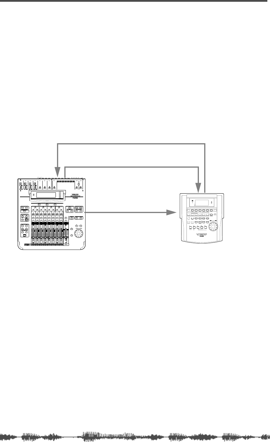
VM200 & MIDI
192 VM200 User’s Guide
MMC (MIDI Machine Control) Send
MMC is an abbreviation for MIDI Machine Control. You can control
MMC-compatible recorders from the VM200 by sending MIDI
Machine Control (MMC) commands.
In MMC Send mode, the VM200’s [ON] keys 1 through 8 function as
the transport keys, store, recall keys for locate memories.
You can use the [EQ EDIT] keys and [SOLO] keys to locate sixteen
definable locate points (LOCATE 1–16).
While you hold down the [ENTER] key, the [SOLO] keys function as
the record track select keys. MMC commands are transmitted via
MIDI.
The following example illustrates remote control of an MMC-compat-
ible digital MTR (such as the Fostex VR800) from the VM200 using
MMC commands.
Setting the Device ID Number
1. Press the [MIDI] key.
The VM200 displays the 1:MIDI TX&RX function page.
2. Select an ID number for the DevID parameter.
Rotate the EQ/LO-MID Freq rotary control to specify the device ID
number of the connected digital MTR. Select a number from 000
to 126.
Entering MMC Send Mode
3. Press the [ROUTING/PHASE] key and the [PAIR/GROUP] key
simultaneously to enter MMC Send mode.
ADAT OUTADAT IN
ADAT IN ADAT OUT
ADAT-compatible Digital multitrack recorder
MIDI Machine Control Data
MIDI IN
SHIFT P.EDIT LOC MEM
RECORD STOP PLAY REW F FWD
AUTO PUNCH
CLIPBOARD
AUTO RTN
OUTIN
ENDOUTINSTART
EJECT
ACCESS
5678
OL
24
12
6
0
1234
RECORD TRACK
4321 5 678
EXECUTE
/ YES
EXIT
/ NO
DISP SEL
UNDO / REDO
EDITHOLD/ STORE SETUP
JOG
VARI PITCH SCRUBLOCATEAUTO PLAY
PGM SEL
AUTO RTN TIME BASE SEL SHUTTLE
LOCATE REC END
LOCATE ABS 0
CLIPBOARD PLAY
PUNCH
AUTO
OPTICAL
A SYNC
PREVIEW
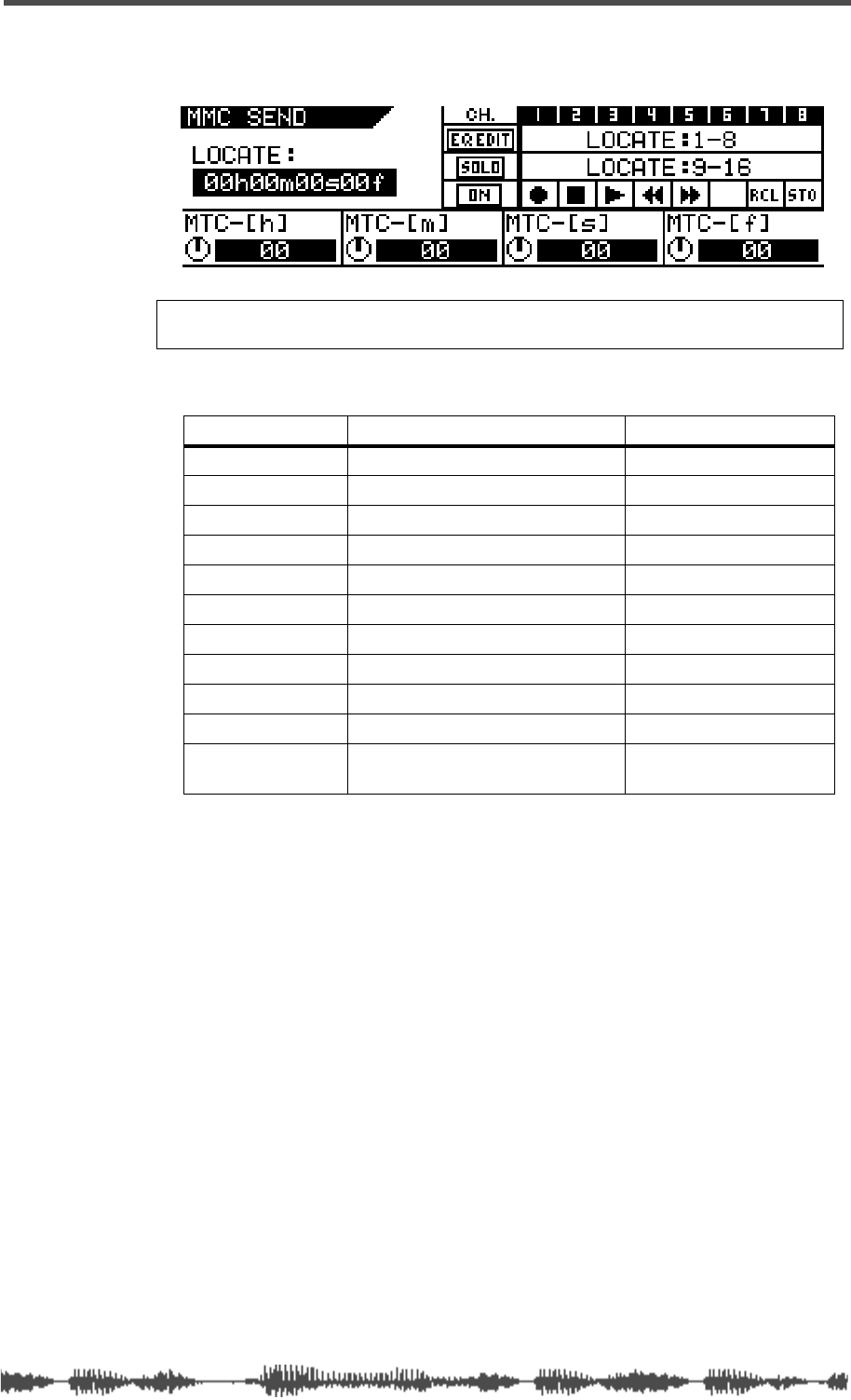
Entering MMC Send Mode
VM200 UserÕs Guide
193
The two keys flash and the VM200 displays the
MMC SEND
function
page.
Refer to the table below for an explanation of the functions and
controls on the
MMC SEND
function page.
4.
Press the
[ON]
keys 1–6 to transmit the transport commands
to the MTR.
To start recording on the MTR, press the channel 1
[ON]
key and
the channel 3
[ON]
key simultaneously.
Note:
Press the [EXIT] key at any time to cancel MMC Send mode and
return to Channel Edit mode.
Key Function MMC Command Value
ON 1
Record 06
ON 2
Stop 01
ON 3
Play 02
ON 4
Rewind 05
ON 5
Fast Forward 04
ON 6
-----
ON 7
Recalls a locate memory.
ON 8
Stores a locate memory.
EQ EDIT 1–8
Locate points 1–8
SOLO 1–8
Locate points 9–16
ENTER + SOLO
1–8
Record track select 1–8
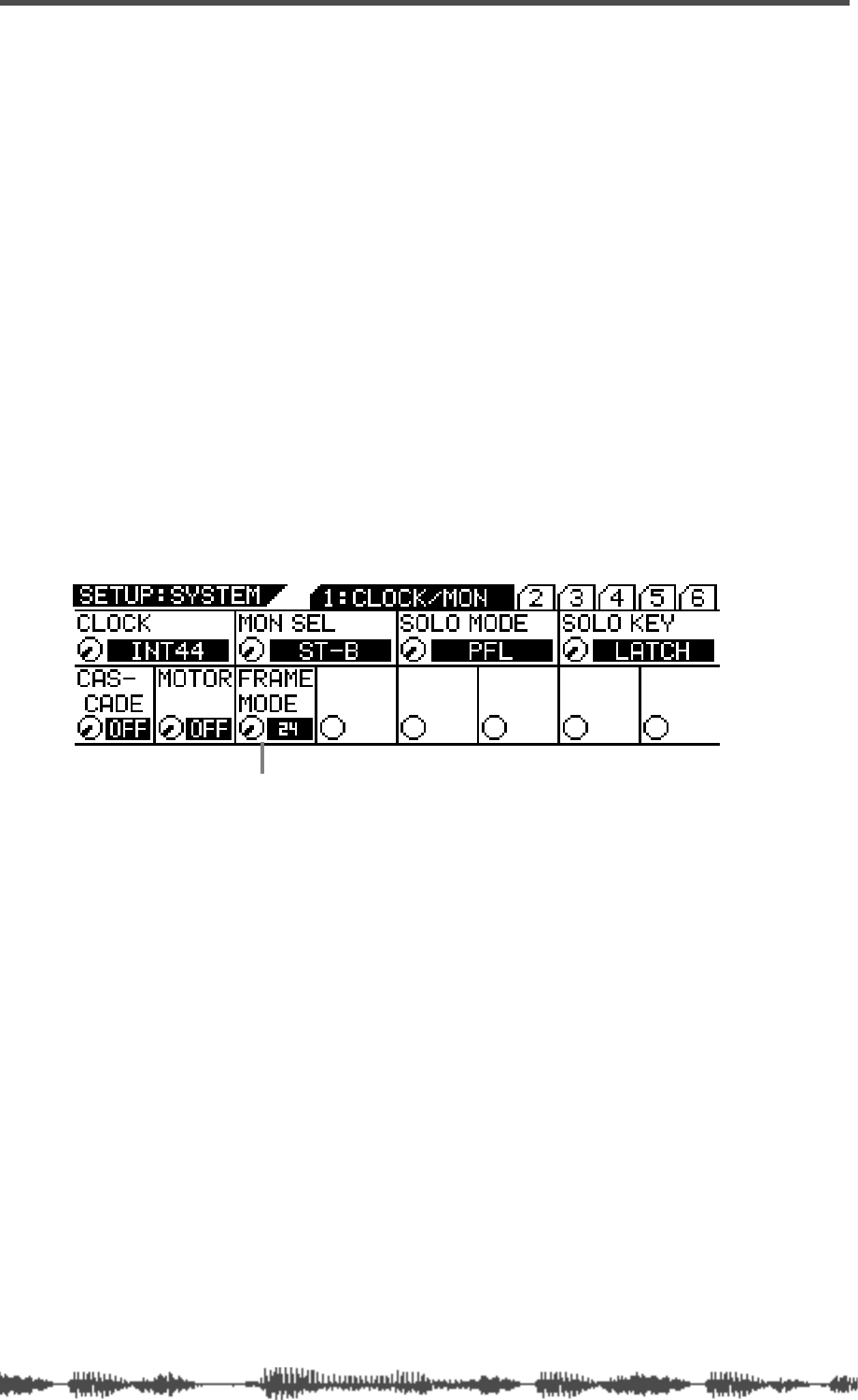
VM200 & MIDI
194
VM200 UserÕs Guide
MMC Send and Timecode
When sending Locate Time in MMC Send mode, the VM200 refers to
the frame rate set by the Frame Mode parameter found on the
SETUP:SYSTEM 1: CLOCK/MON
function page.
Before you can correctly set a locate time on the VM200 to locate a
position on a connected external digital recorder via MMC Send com-
mands, you need to set the correct frame rate for the timecode.
The VM200 supports four frame rates: 24, 25, 30D (drop-frame), and
30fps.
It is important that you set the timecode frame rate to match the
material recorded on the digital recorder. Otherwise, the locate point
you set on the VM200 will be out of sync with the recorded material.
Frame Mode
Follow the steps below to set the frame rate for the MIDI timecode.
1.
Press the
[SYSTEM]
key.
The system displays the
SETUP:SYSTEM
1:CLOCK/MON
function page.
2.
Specify a value for the Frame Mode parameter by rotating the
EQ/LO-MID Freq control.
The Frame Mode parameter specifies the frame rate. Select a
frame rate appropriate for your project.
The options include 24, 25, 30DF (drop-frame), and 30ND
(non-drop frame).
The default setting is 24.
3.
Press the
[CHANNEL/METER]
key or the
[EXIT]
key.
The VM200 returns to the previous mode.
Alternatively, press the
[ROUTING/PHASE]
key and the
[PAIR/GROUP]
key simultaneously to select MMC Send mode
immediately after you set the Frame Mode parameter.
FRAME MODE
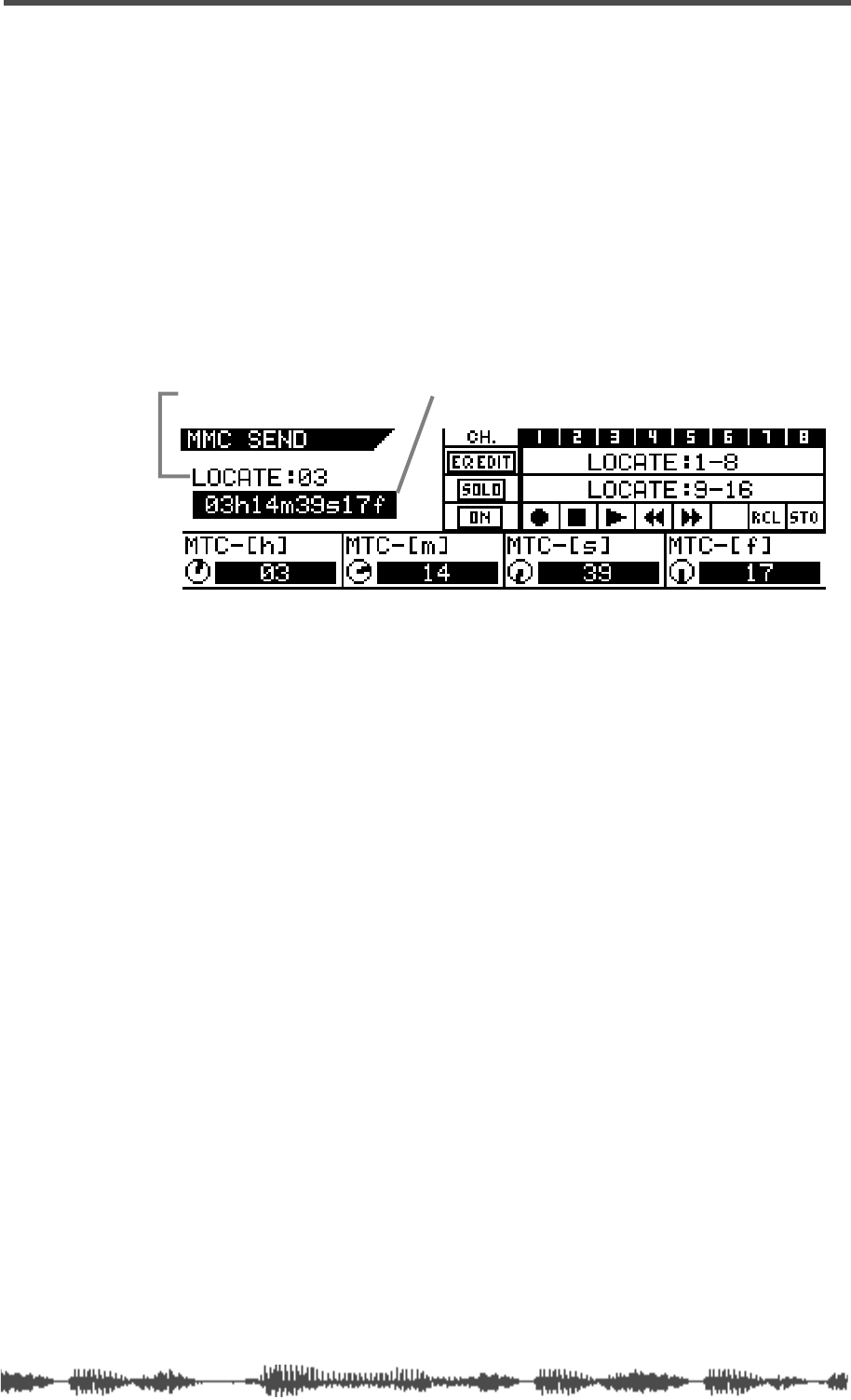
Storing Locate Points
VM200 UserÕs Guide
195
Storing Locate Points
Follow the steps below to store a locate point to the desired Locate
key.
1.
While the
MMC SEND
function page is displayed, rotate the
[GAIN] rotary controls to set the locate times in hours, min-
utes, seconds, and frames.
The
EQ/LO GAIN
rotary control adjusts the hours (MTC-[h]).
The
EQ/LO-MID GAIN
rotary control adjusts the minutes
(MTC-[m]).
The
EQ/HI-MID GAIN
rotary control adjusts the seconds (MTC-[s]).
The
EQ/HI GAIN
rotary control the frames (MTC-[f]).
2.
Press the channel 8
[ON]
key (functioning as the
STORE
key),
then press an
[EQ EDIT]
or
[SOLO]
key to specify where you
wish to store the locate point.
The VM200 displays the locate point in the upper-left of the dis-
play.
Checking the Locate Points
You can check the locate points memorized into the Locate keys as
follows:
3.
While the
MMC SEND
function page is displayed, press the chan-
nel 7
[ON]
key (functioning as the
RECALL
key), then press the
Locate key for the Locate point you wish to check.
The VM200 displays the locate point in the upper-left of the dis-
play.
Transmitting the Locate Commands
4.
Press the desired
[EQ EDIT]
or
[SOLO]
keys 1–16 (functioning as
Locate keys 1–16) to transmit the locate commands to the
recorder.
Note that you can store Locate points using the MIDI Bulk Dump
function. See “Bulk Dump” on page 189.
LOCATE TIME
LOCATE POINT

VM200 & MIDI
196 VM200 User’s Guide

DIGITAL RECORDING MIXER
VM200
REC BUSS
EFF EDITSELECTED EQ
EQ/HI
EQ/HI-MIDEQ/LO-MID
+10
0
-10
-20
-30
-40
-
+10
0
-10
-20
-30
-40
-
+10
0
-10
-20
-30
-40
-
+10
0
-10
-20
-30
-40
-
+10
0
-10
-20
-30
-40
-
+10
0
-10
-20
-30
-40
-
+10
0
-10
-20
-30
-40
-
GAIN
FREQ
PAN
Q
PAN
ON ON ON ON ON ON ON
SOLO SOLO SOLO SOLO SOLO SOLO SOLO
EQ EDIT EQ EDIT EQ EDIT EQ EDIT EQ EDIT EQ EDIT EQ EDIT EQ EDIT
SOLO
ON ON
SOLO
EQ LIBRARY
STORERECALL
EQ ON
EFF LIBRARY
STORERECALL
EFF2EFF1
RECALLSOLO
EXIT
14
6
13
5
12
4
11
3
2019
FREQ QFREQ Q
Q
GAINGAIN
9-16 ADAT IN 17-20 EFF RTN
P
AGE SELECT
GROUP
PAIR/
METER
CHANNEL/
MIN MAX
+10
0
1
0
1
0
0
-10
-20
-30
-60
-
-40
MMC SEND
PANPANPANPANPANPAN
-40
-36
-24
-18
1212
ST BUSS/SOLO
L R
VM200 User’s Guide
197
CHAPTER 12
Initializing the VM200
About This Chapter
This brief chapter describes how to re-initialize the VM200 to reset
all parameters to their original default values.
Chapter Contents
Initializing the VM200 . . . . . . . . . . . . . . . . . . . . . . . . . . . 198
Default Setup Parameters. . . . . . . . . . . . . . . . . . . . . . . . . 200
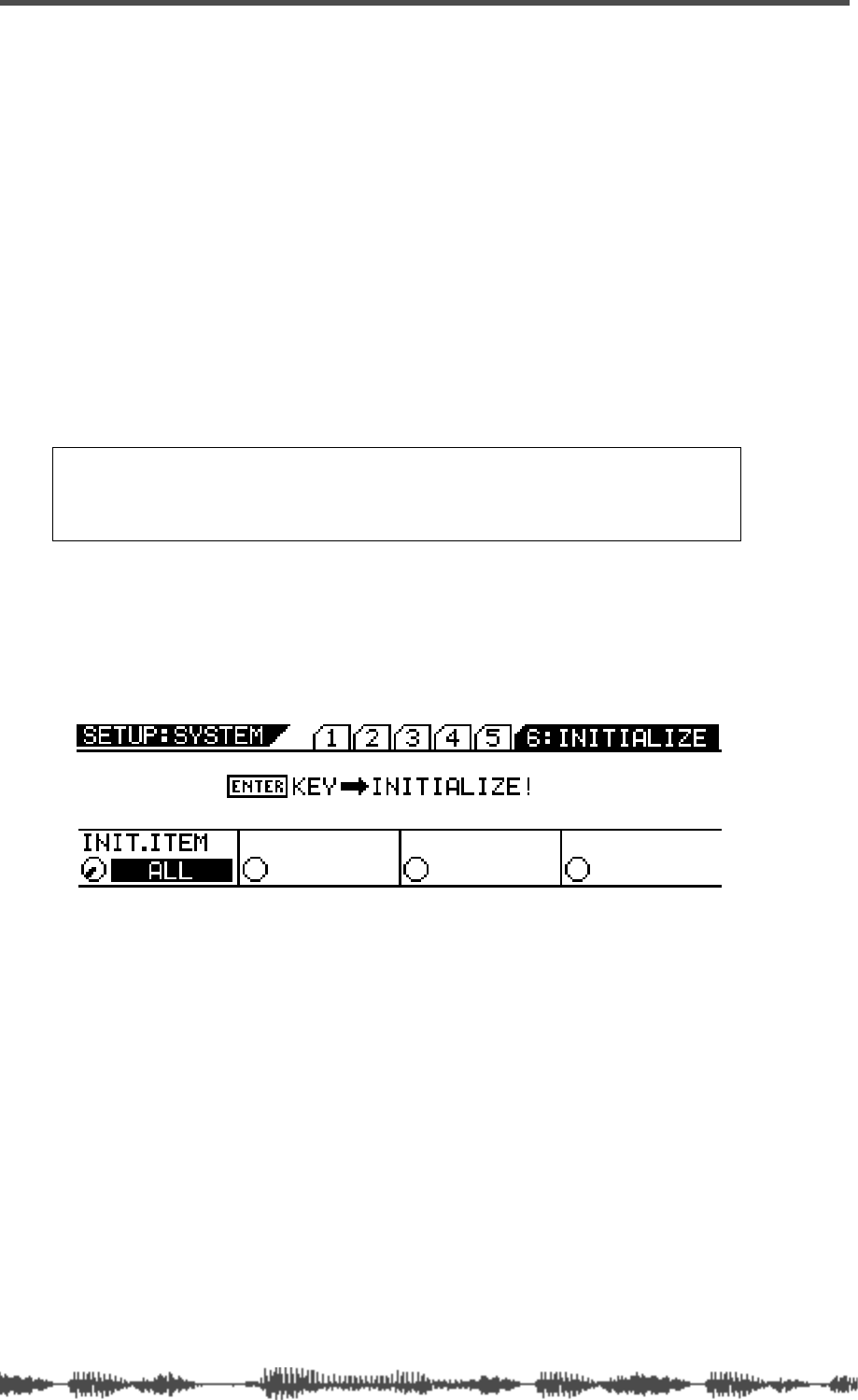
Initializing the VM200
198
VM200 User’s Guide
Initializing the VM200
You can initialize the VM200 to its factory default settings by using
the Initialization function.
You can specify the items you wish to initialize, choosing from the fol-
lowing options:
❑
ALL (all parameters)
❑
SCENE MEM. (Scene Memory)
❑
EQ LIBRARY
❑
EFF LIBRARY
❑
PGM C. TABLE (Program Change Table)
❑
CTRL C. TABLE (Control Change Table)
❑
SETUP
Follow the steps below to initialize the VM200.
1.
Press the
[SYSTEM]
key repeatedly to display the
6: INITIALIZE
function page.
2.
Rotate the EQ/LO Gain control to select the desired item.
Select from the following options:
• ALL (all parameters)
• SCENE MEM. (Scene Memory)
• EQ LIBRARY
• EFF LIBRARY
• PGM C. TABLE (Program Change Table)
• CTRL C. TABLE (Control Change Table)
• SETUP
The selected item flashes.
Note:
If you want to reset only the mix settings and retain other param-
eter settings, recall one of the preset scene memories P0, P1, or P2
instead. See the chapter entitled “Scene Memory” on page 147 for more
information.
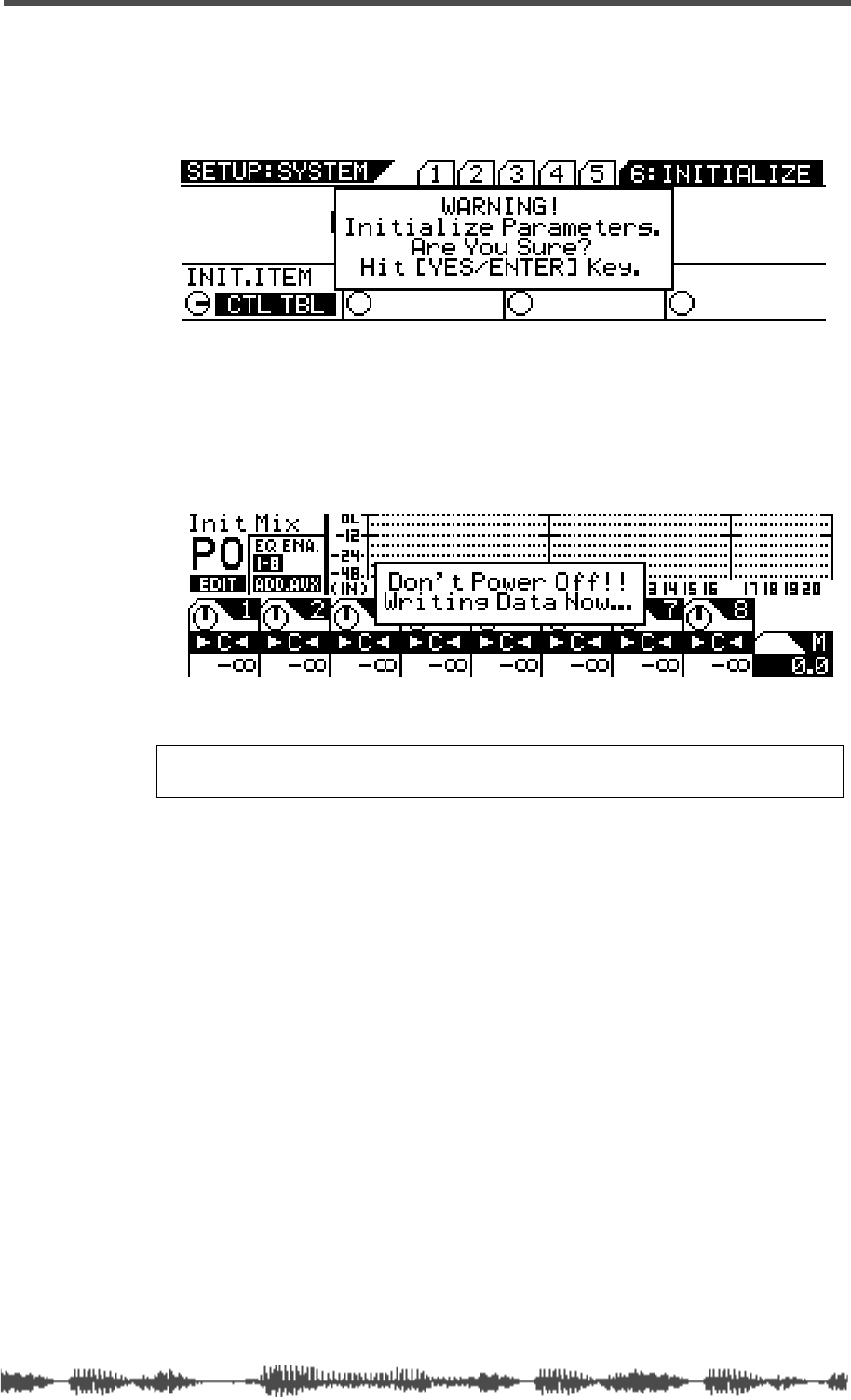
Initializing the VM200
VM200 User’s Guide
199
3.
Press the
[ENTER]
key.
The selected item lights up continuously, and a “YES/ENTER” dia-
log appears.
4.
Press the
[ENTER]
key to initialize the specified settings, or
press the
[EXIT]
key to return to the previous screen.
If you press the
[ENTER]
key, a warning message appears and the
VM200 starts initializing its settings.
Warning:
Do not power off the VM200 while it is writing to the
flash memory or you may damage the VM200.
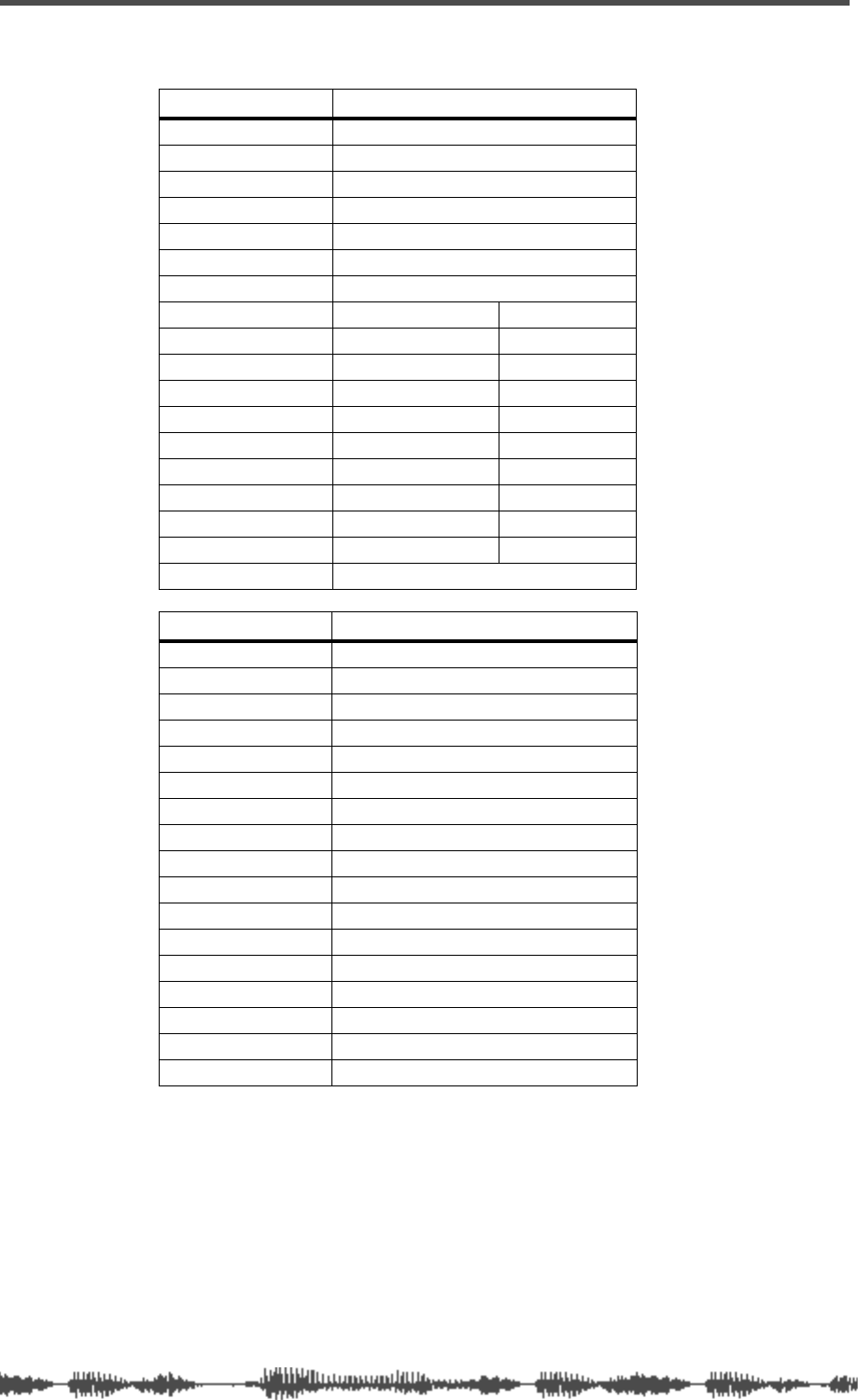
Initializing the VM200
200
VM200 User’s Guide
Default Setup Parameters
System Parameters Value
CLOCK SEL INT44
MON SEL ST-B
SOLO MODE PFL
SOLO KEY LATCH
CASCADE OFF
MOTOR ON
FRAME MODE 24
RECALL SAFE CH. FADER OFF
CH. PAN OFF
CH. ON OFF
ROUTING OFF
AUX1–4 OFF
EFF1/2 OFF
EQ OFF
EQ ON OFF
Ch1–20 ALL OFF
SOLO SAFE Ch1–20 ALL OFF
POWER ON RCL LAST-STORED
MIDI Parameters Value
Tx CH 1
Rx CH OMNI
ECHO OFF
BULK Rx ON
PG Tx ON
PG Rx ON
PG Table 1 (User)
CC Tx OFF
CC Rx OFF
CC Table 1 (User)
SySEx Tx&Rx OFF
SysEx DevID 0
PGM C. TABLE1 Same as PGM C. TABLE 2(preset)
CTL C. TABLE1 Same as CTL C. TABLE2 (preset)
ITEM ALL
BLOCK ---
INTERVAL 0ms

DIGITAL RECORDING MIXER
VM200
REC BUSS
EFF EDITSELECTED EQ
EQ/HI
EQ/HI-MIDEQ/LO-MID
+10
0
-10
-20
-30
-40
-
+10
0
-10
-20
-30
-40
-
+10
0
-10
-20
-30
-40
-
+10
0
-10
-20
-30
-40
-
+10
0
-10
-20
-30
-40
-
+10
0
-10
-20
-30
-40
-
+10
0
-10
-20
-30
-40
-
GAIN
FREQ
PAN
Q
PAN
ON ON ON ON ON ON ON
SOLO SOLO SOLO SOLO SOLO SOLO SOLO
EQ EDIT EQ EDIT EQ EDIT EQ EDIT EQ EDIT EQ EDIT EQ EDIT EQ EDIT
SOLO
ON ON
SOLO
EQ LIBRARY
STORERECALL
EQ ON
EFF LIBRARY
STORERECALL
EFF2EFF1
RECALLSOLO
EXIT
14
6
13
5
12
4
11
3
2019
FREQ QFREQ Q
Q
GAINGAIN
9-16 ADAT IN 17-20 EFF RTN
P
AGE SELECT
GROUP
PAIR/
METER
CHANNEL/
MIN MAX
+10
0
1
0
1
0
0
-10
-20
-30
-60
-
-40
MMC SEND
PANPANPANPANPANPAN
-40
-36
-24
-18
1212
ST BUSS/SOLO
L R
VM200 User’s Guide
201
APPENDIX
Specifications and Data
Chapter Contents
Display Warning Messages . . . . . . . . . . . . . . . . . . . . . . . . 202
Specifications . . . . . . . . . . . . . . . . . . . . . . . . . . . . . . . . . . 203
Maintenance. . . . . . . . . . . . . . . . . . . . . . . . . . . . . . . . . . . 205
Tables & Data. . . . . . . . . . . . . . . . . . . . . . . . . . . . . . . . . . 206
Channel Fader Gain Table . . . . . . . . . . . . . . . . . . . . . . 206
Master Fader Gain . . . . . . . . . . . . . . . . . . . . . . . . . . . . . . 207
Pan Gain . . . . . . . . . . . . . . . . . . . . . . . . . . . . . . . . . . . . . 208
Q . . . . . . . . . . . . . . . . . . . . . . . . . . . . . . . . . . . . . . . . . 208
EQ Frequency. . . . . . . . . . . . . . . . . . . . . . . . . . . . . . . . . . 209
Program Change To Scene Memory Assignment Tables. . . 210
Program Change Assign Table 1 (User) . . . . . . . . . . . . . 210
Program Change Assign Table 2 (Preset) . . . . . . . . . . . . 210
Control Change To Control Parameters Assignment Tables 211
Control Change Assign Table 1 (User). . . . . . . . . . . . . . 211
Control Change Assign Table 2 (Preset). . . . . . . . . . . . . 212
Preset Scene Parameters. . . . . . . . . . . . . . . . . . . . . . . . . . 213
MIDI In/Out Data Format. . . . . . . . . . . . . . . . . . . . . . . . . 216
MIDI Implementation Chart . . . . . . . . . . . . . . . . . . . . . . . 225
Declaration of EC Directive. . . . . . . . . . . . . . . . . . . . . . . . 226
Fostex Distributors List In Europe . . . . . . . . . . . . . . . . . . 226
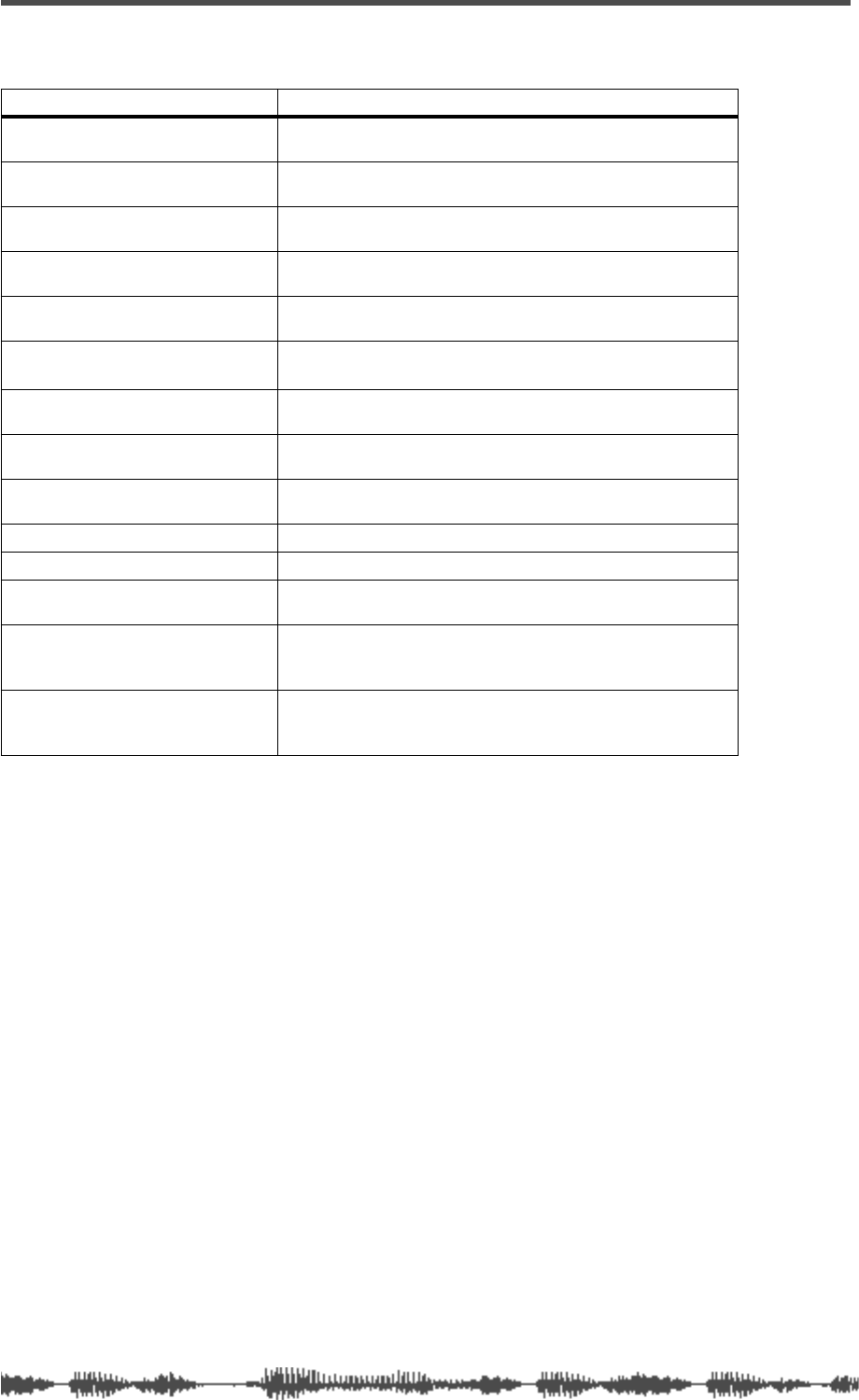
202
VM200 User’s Guide
Display Warning Messages
Warning Messages Meaning
EQ 1–8 Invalid! (EQ Enable 9–16)
The EQ ENABLE setting of the channel you are operating is
not turned ON, thus the EQ is not available for that channel.
EQ 9–16 Invalid! (EQ Enable 1–8)
The EQ ENABLE setting of the channel you are operating is
not turned ON, thus the EQ is not available for that channel.
Channel Invalid!
You have tried to operate channels 21–24, which are not
available.
AUX 3/4 Invalid! (ADD.AUX Off)
ADD AUX parameter is turned off, and AUX3/4 are not avail-
able.
REC BUSS Invalid! (AD.AUX On)
ADD AUX parameter is turned on, and REC BUSS is not
available.
EFF 1/2 Invalid! (EQ Enable
1–16)
EQ is enabled for channels 1–16, and effects are not avail-
able.
+48V SW On!
The phantom power is turned on. (This appears when pow-
ering up the mixer.)
Byte Count Error in BULK DATA!
The byte count of the received Bulk Dump data is not cor-
rect.
Check Sum Error in BULK DATA!
The check sum of the received Bulk Dump data is not cor-
rect.
MIDI IN Buffer Full!
The VM200 has received too much MIDI data.
MIDI OUT Buffer Full!
The VM200 has transmitted too much MIDI data.
Wrong WORD-IN CLK
The word clock received from the connected device is not
correct and the VM200 cannot synchronize correctly.
Wrong ADAT-IN CLK!
Digital signals from the ADAT IN connector are not word
clock synchronized with the VM200, and noise may infiltrate
the audio data.
Wrong S/P DIF-IN CLK!
Digital signals from the S/P DIF-IN connector are not word
clock synchronized with the VM200, and noise may infiltrate
the audio data.
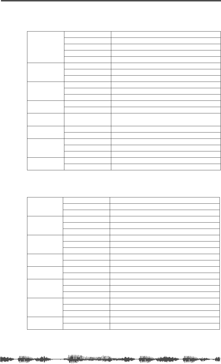
Specifications
VM200 User’s Guide
203
Specifications
Inputs
Outputs
ANALOG IN
(ch1-ch4)
Connector XLR3-31 (1: Ground, 2: Hot, 3: Cold), 1/4-inch phone jack
A/B switch A: XLR3-31 (mics), B: 1/4-inch phone jack (lines)
Input impedance 3k
Ω
or higher (mics), 10k
Ω
or higher (lines)
PAD switch 26dB (+2dB, –1dB)
PHANTOM switch +48V (+1V, –2V)
ANALOG IN
(ch5-ch8)
Connector 1/4-inch phone jack
Input impedance 10k
Ω
or higher
Nominal input level –10dBV
INSERT IN
(ch1-ch4)
Connector 1/4-inch phone jack
Input impedance 10k
Ω
or higher
Nominal input level –10dBV
ADAT IN Connector Optical (Toslink)
Format Adat format
EFFECT RTN
1
(ch17–ch20)
1. Effect returns for the internal effects processor
Connector none
S/P DIF IN
2
2. Assignable to any consecutive odd/even channels
Connector Optical (Toslink)
Format IEC60958 (S/P DIF)
2TRACK IN
Connector RCA pin jack (x2)
Input impedance 10k
Ω
or higher
Nominal input level –10dBV
WORD IN Connector BNC
Level TTL/75
Ω
(with Terminate ON/OFF switch)
AUX OUT (1, 2)
Connector 1/4-inch phone jack (x2)
Applicable impedance 10k
Ω
or higher
Nominal output level –10dBV
REC BUSS
OUT
1
(1,2)
Connector 1/4-inch phone jack (x2)
Input impedance 10k
Ω
or higher
Nominal input level –10dBV
STEREO OUT
(L, R)
Connector 1/4-inch phone jack (x2)
Input impedance 10k
Ω
or higher
Nominal input level –10dBV
S/P DIF OUT Connector Optical (Toslink)
Format IEC60958 (S/P DIF)
ADAT OUT Connector Optical (Toslink)
Format Adat format
MON OUT (L, R)
Connector RCA pin jack (x2)
Applicable impedance 10k
Ω
or higher
Nominal output level –10dBV
PHONES
Connector 1/4-inch phone jack (x1)
Input impedance 8k
Ω
or higher
Max. output level 50mW or higher (at 32
Ω
)
WORD OUT Connector BNC
Level TTL/75
Ω
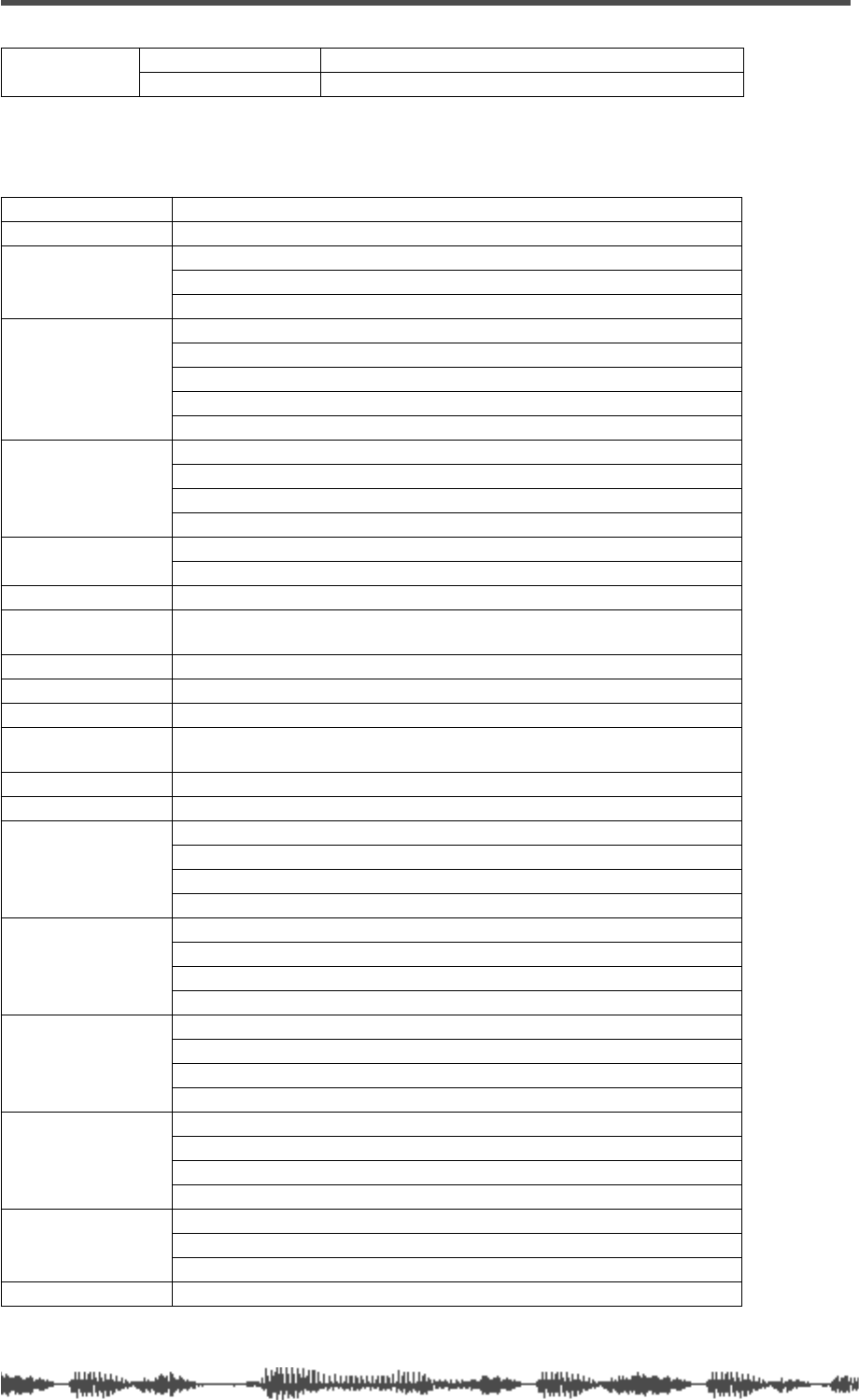
204
VM200 User’s Guide
General
MIDI Connector DIN 5-pin (x3)
IN/OUT/THRU Format MIDI standards
1. The default setting is REC BUSS. However, with the ADD.AUX parameter turned on, AUX3/4
are available, and these connectors function as AUX OUT 3/4, providing four AUX SENDs.
Frequency response 20Hz–20kHz, +1dB/-3dB (phones: 50Hz–20kHz, +1dB/-3dB)
Dynamic range 90dB or higher (LINE IN CH IN –> ST OUT)
Total harmonic
distortion
CH IN–>ST OUT: 0.08% or less (at 0dBV output)
LINE IN–>ST OUT: 0.008% or less (at 0dBV output)
LINE IN–>PHONES OUT: 0.05% or less (at 50mW/33)
Residual noise
AUX1-4, ST BUSS OUT: -90dB or less (master fader = min, all ch faders = min)
AUX1-4, ST OUT: -78dB or less (master fader = 0dB, all ch faders = 0dB)
MIC->INSERT: –71dBV or less (gain=max, pad=off, Rs=150)
MONITOR OUT (min): –100dBV or less
PHONES (min): -98dBV or less
S/N 1–4CH CH IN (–4dB)–>AUX1-4, ST BUSS OUT: 92dB or higher (IHF-A)
CH IN (–48dB)–>AUX1-4, ST BUSS OUT: 76dB or higher (IHF-A)
5–8CH CH IN (–4dB)–>AUX1-4, ST BUSS OUT: 92dB or higher (IHF-A)
CH IN (–38dB)–>AUX1-4, ST BUSS OUT: 82dB or higher (IHF-A)
Mic gain 1–4CH: 50dB (+3dB -1dB)
5–8CH: 40dB (+3dB -1dB)
Crosstalk 70dB or higher (@ 1kHz), phone: 53dB or higher
PHONES max
output 50mW or higher, impedance 32
Ω
, 1kHz
A/D 20bit, 64-times oversampling
∆∑
modulation
D/A 20bit, 128-times oversampling
∆∑
modulation
Fader Motor-driven, 128 steps/60mm
Sampling frequency Internal: 44.1kHz fixed
External (S/PDIF, ADAT, WORD): 44.1kHz/48kHz+/–6%
Internal processing 32-bit
Equalizer 4-band parametric (LO, LO-MID, HI-MID, HI)
EQ LO
Type: Peaking (bell) or Lo shelving or High Pass Filter
f: 20.3Hz–4.00kHz (1/24 octave/step)
Gain: +/–18dB (0.5dB step)
Q: 0.1–20 (45 steps)
EQ LO-MID
Type: Peaking (bell)
f: 20.3Hz–4.00kHz (1/24 octave steps)
Gain: +/–18dB (0.5dB step)
Q: 0.1–20 (45 steps)
EQ HI-MID
Type: Peaking (bell)
f: 500Hz–20.2kHz (1/24 octave steps)
Gain: +/–18dB (0.5dB step)
Q: 0.1–20 (45 steps)
EQ HI
Type: Peaking (bell) or Lo shelving or High Pass Filter
f: 500Hz–20.2kHz (1/24 octave steps)
Gain: +/–18dB (0.5dB step)
Q: 0.1–20 (45 steps)
Memory
Scene memory: 3 (preset) + 100 (user)
Effect library: 50 (preset) + 50 (user)
EQ library: 50 (preset) + 50 (user)
Display STN graphic LCD (256 x 64 dots)
Maintenance
VM200 User’s Guide
205
❑
Specifications and appearance are subject to change without notice for
product improvement.
❑
“Adat” and the symbol are trademarks of Alesis Corporation.
Maintenance
For normal cleaning, use a soft dry cloth.
For stubborn dirt, moisten a cloth in diluted detergent, wring it out
firmly, and wipe the dirt off. Then polish the VM200 with a dry cloth.
Dimensions 16
13
/
16
(W) X 4
5
/
8
(H) X 17
7
/
8
(D) inches
(428(W) X 118(H) X 454(D) mm)
Weight Approx. 15.4 pounds (7kg)
Power source
90V–250V (50Hz/60Hz):
120VAC 60Hz(US, Canada), 230V– 50/60Hz(Europe)
100VAC 50/60Hz(JPN)
Power consumption
30W
Note:
Never use solvents such as alcohol, thinner, or benzene, since
these will damage the printing and finish of the exterior.
OPTICAL
206
VM200 UserÕs Guide
Tables & Data
Channel Fader Gain Table
No.
Calculated
Gain (dB)
Displayed
Gain (dB)
No.
Calculated
Gain (dB)
Displayed
Gain (dB)
No.
Calculated
Gain (dB)
Displayed
Gain (dB)
0
-
∞
-
∞
43
-18.70 -18.7
86
-5.90 -5.9
1
-72.30 -72.0
44
-18.30 -18.3
87
-5.60 -5.6
2
-66.20 -66.0
45
-17.90 -17.9
88
-5.30 -5.3
3
-60.20 -60.0
46
-17.50 -17.5
89
-5.00 -5.0
4
-57.40 -57.5
47
-17.10 -17.1
90
-4.65 -4.7
5
-55.30 -55.0
48
-16.75 -16.8
91
-4.30 -4.3
6
-53.20 -53.0
49
-16.40 -16.4
92
-3.90 -3.9
7
-51.00 -51.0
50
-16.05 -16.1
93
-3.50 -3.5
8
-49.00 -49.0
51
-15.70 -15.7
94
-3.10 -3.1
9
-46.90 -47.0
52
-15.35 -15.4
95
-2.70 -2.7
10
-45.00 -45.0
53
-15.00 -15.0
96
-2.30 -2.3
11
-43.30 -43.5
54
-14.70 -14.7
97
-1.90 -1.9
12
-41.60 -42.0
55
-14.40 -14.4
98
-1.50 -1.5
13
-40.00 -40.0
56
-14.10 -14.1
99
-1.10 -1.1
14
-38.60 -38.5
57
-13.80 -13.8
100
-0.70 -0.7
15
-37.30 -37.0
58
-13.50 -13.5
101
-0.35 -0.4
16
-36.10 -36.0
59
-13.20 -13.2
102
0.00 0.0
17
-35.00 -35.0
60
-12.90 -12.9
103
+0.35 +0.4
18
-33.90 -34.0
61
-12.60 -12.6
104
+0.70 +0.7
19
-32.80 -33.0
62
-12.30 -12.3
105
+1.05 +1.1
20
-31.80 -32.0
63
-12.00 -12.0
106
+1.40 +1.4
21
-30.90 -31.0
64
-11.75 -11.8
107
+1.80 +1.8
22
-30.10 -30.0
65
-11.50 -11.5
108
+2.20 +2.2
23
-29.40 -29.0
66
-11.25 -11.3
109
+2.60 +2.6
24
-28.70 -28.5
67
-11.00 -11.0
110
+3.00 +3.0
25
-28.00 -28.0
68
-10.75 -10.8
111
+3.40 +3.4
26
-27.40 -27.5
69
-10.50 -10.5
112
+3.80 +3.8
27
-26.80 -27.0
70
-10.25 -10.3
113
+4.20 +4.2
28
-26.20 -26.0
71
-10.00 -10.0
114
+4.60 +4.6
29
-25.60 -25.5
72
-9.75 -9.8
115
+5.00 +5.0
30
-25.00 -25.0
73
-9.50 -9.5
116
+5.40 +5.4
31
-24.50 -24.5
74
-9.25 -9.3
117
+5.80 +5.8
32
-24.00 -24.0
75
-9.00 -9.0
118
+6.20 +6.2
33
-23.50 -23.5
76
-8.75 -8.8
119
+6.60 +6.6
34
-23.00 -23.0
77
-8.50 -8.5
120
+7.00 +7.0
35
-22.50 -22.5
78 -8.25 -8.3 121 +7.40 +7.4
36 -22.00 -22.0 79 -8.00 -8.0 122 +7.80 +7.8
37 -21.50 -21.5 80 -7.60 -7.6 123 +8.20 +8.2
38 -21.00 -21.0 81 -7.40 -7.4 124 +8.60 +8.6
39 -20.50 -20.5 82 -7.10 -7.1 125 +9.00 +9.0
40 -20.00 -20.0 83 -6.80 -6.8 126 +9.50 +9.5
41 -19.55 -19.5 84 -6.50 -6.5 127 +10.00 +10.0
42 -19.10 -19.1 85 -6.20 -6.2
Master Fader Gain
VM200 User’s Guide 207
Master Fader Gain
No.
Calculated
Gain (dB)
Displayed
Gain (dB)
No.
Calculated
Gain (dB)
Displayed
Gain (dB)
No.
Calculated
Gain (dB)
Displayed
Gain (dB)
0-∞-∞43 -35.80 -35.8 86 -15.18 -15.2
1-90.00 -90.0 44 -35.10 -35.1 87 -14.81 -14.8
2-84.00 -84.0 45 -34.40 -34.4 88 -14.44 -14.4
3-80.00 -80.0 46 -33.70 -33.7 89 -14.07 -14.1
4-78.00 -78.0 47 -33.00 -33.0 90 -13.70 -13.7
5-76.00 -76.0 48 -32.40 -32.4 91 -13.33 -13.3
6-74.00 -74.0 49 -31.80 -31.8 92 -12.96 -13.0
7-72.00 -72.0 50 -31.20 -31.2 93 -12.59 -12.6
8-70.00 -70.0 51 -30.60 -30.6 94 -12.22 -12.2
9-68.70 -68.7 52 -30.00 -30.0 95 -11.85 -11.9
10 -67.40 -67.4 53 -29.50 -29.5 96 -11.48 -11.5
11 -66.20 -66.2 54 -29.00 -29.0 97 -11.11 -11.1
12 -64.30 -64.3 55 -28.50 -28.5 98 -10.74 -10.7
13 -62.70 -62.7 56 -28.00 -28.0 99 -10.37 -10.4
14 -61.40 -61.4 57 -27.50 -27.5 100 -10.00 -10.0
15 -59.90 -60.0 58 -27.00 -27.0 101 -9.62 -9.6
16 -58.50 -58.5 59 -26.50 -26.5 102 -9.25 -9.3
17 -57.20 -57.2 60 -26.00 -26.0 103 -8.88 -8.9
18 -56.00 -56.0 61 -25.50 -25.5 104 -8.51 -8.5
19 -54.70 -54.7 62 -25.00 -25.0 105 -8.14 -8.1
20 -53.50 -53.5 63 -24.50 -24.5 106 -7.77 -7.8
21 -52.40 -52.4 64 -24.00 -24.0 107 -7.40 -7.4
22 -51.10 -51.2 65 -23.50 -23.5 108 -7.03 -7.0
23 -50.00 -50.0 66 -23.05 -23.1 109 -3.66 -3.7
24 -49.20 -49.2 67 -22.60 -22.6 110 -6.29 -6.3
25 -48.40 -48.4 68 -22.15 -22.2 111 -5.92 -5.9
26 -47.70 -47.7 69 -21.70 -21.7 112 -5.55 -5.6
27 -47.00 -47.0 70 -21.25 -21.3 113 -5.18 -5.2
28 -46.30 -46.3 71 -20.80 -20.8 114 -4.81 -4.8
29 -45.60 -45.6 72 -20.40 -20.4 115 -4.44 -4.4
30 -44.90 -44.9 73 -20.00 -20.0 116 -4.07 -4.1
31 -44.20 -44.2 74 -19.62 -19.6 117 -3.70 -3.7
32 -43.50 -43.5 75 -19.25 -19.3 118 -3.33 -3.3
33 -42.80 -42.8 76 -18.88 -18.9 119 -2.96 -3.0
34 -42.10 -42.1 77 -18.51 -18.5 120 -2.59 -2.6
35 -41.40 -41.4 78 -18.14 -18.1 121 -2.22 -2.2
36 -40.70 -40.7 79 -17.77 -17.8 122 -1.85 -1.9
37 -40.00 -40.0 80 -17.40 -17.4 123 -1.48 -1.5
38 -39.30 -39.3 81 -17.03 -17.0 124 -1.11 -1.1
39 -38.60 -38.6 82 -16.66 -16.7 125 -0.74 -0.7
40 -37.90 -37.9 83 -16.29 -16.3 126 -0.37 -0.4
41 -37.20 -37.2 84 -15.92 -15.9 127 0.00 0.0
42 -36.50 -36.5 85 -15.55 -15.6
208
VM200 UserÕs Guide
Pan Gain
Q
HI: 0.1–20 (45 steps), HI-shelving, LPF
HI-MID, LO-MID: 0.1–20 (45 steps)
LO: 0.1–20 (45 steps), LO-shelving, HPF
No.
Gain
Left
(dB)
Gain
Right
(dB)
Displayed
Pan
No.
Gain
Left
(dB)
Gain
Right
(dB)
Displayed
Pan
No.
Gain
Left
(dB)
Gain
Right
(dB)
Displayed
Pan
0
0.0 -
∞
<–L
14
-1.8 -7.1 L3.0
28
-9.0 -1.4 R4.0
1
-0.1 -32.0 L9.5
15
-2.0 -6.3 L2.5
29
-10.2 -1.2 R4.5
2
-0.2 -27.0 L9.0
16
-2.2 -5.5 L2.0
30
-11.6 -1.0 R5.0
3
-0.25 -23.5 L8.5
17
-2.4 -4.8 L1.5
31
-13.2 -0.8 R5.5
4
-0.3 -21.0 L8.0
18
-2.6 -4.2 L1.0
32
-15.0 -0.6 R6.0
5
-0.35 -19.0 L7.5
19
-2.8 -3.6 L0.5
33
-16.1 -0.5 R6.5
6
-0.4 -17.4 L7.0
20
-3.0 -3.0
CENTER
34
-17.4 -0.4 R7.0
7
-0.5 -16.1 L6.5
21
-3.6 -2.8 R0.5
35
-19.0 -0.35 R7.5
8
-0.6 -15.0 L6.0
22
-4.2 -2.6 R1.0
36
-21.0 -0.3 R8.0
9
-0.8 -13.2 L5.5
23
-4.8 -2.4 R1.5
37
-23.5 -0.25 R8.5
10
-1.0 -11.6 L5.0
24
-5.5 -2.2 R2.0
38
-27.0 -0.2 R9.0
11
-1.2 -10.2 L4.5
25
-6.3 -2.0 R2.5
39
-32.0 -0.1 R9.5
12
-1.4 -9.0 L4.0
26
-7.1 -1.8 R3.0
40
-
∞
0.0 R–>
13
-1.6 -8.0 L3.5
27
-8.0 -1.6 R3.5
No.
Q
No.
Q
No.
Q
0
0.10
15
0.56
30
3.2
1
0.11
16
0.63
31
3.5
2
0.13
17
0.71
32
4.0
3
0.14
18
0.79
33
4.5
4
0.16
19
0.89
34
5.0
5
0.18
20
1.0
35
5.6
6
0.20
21
1.1
36
6.3
7
0.22
22
1.3
37
7.1
8
0.25
23
1.4
38
7.9
9
0.28
24
1.6
39
8.9
10
0.32
25
1.8
40
10
11
0.35
26
2.0
41
11
12
0.40
27
2.2
42
13
13
0.45
28
2.5
43
16
14
0.50
29
2.8
44
20
EQ Frequency
VM200 UserÕs Guide
209
EQ Frequency
Range: 20.3Hz – 20.2kHz (240 steps per 1/24 octave)
No.
Freq
(display)
No.
Freq
(display)
No.
Freq
(display)
No.
Freq
(display)
No.
Freq
(display)
No.
Freq
(display)
0
20.3
40
64.3
80
204
120
648
160
2.06K
200
6.54K
1
20.9
41
66.2
81
210 121 667 161 2.12K 201 6.73K
221.5 42 68.2 82 216 122 687 162 2.18K 202 6.92K
322.1 43 70.2 83 223 123 707 163 2.24K 203 7.13K
422.7 44 72.2 84 229 124 728 164 2.31K 204 7.34K
523.4 45 74.3 85 236 125 749 165 2.38K 205 7.55K
624.1 46 76.5 86 243 126 771 166 2.45K 206 7.77K
724.8 47 78.7 87 250 127 794 167 2.52K 207 8.00K
825.5 48 81.1 88 257 128 817 168 2.59K 208 8.23K
926.3 49 83.4 89 265 129 841 169 2.67K 209 8.48K
10 27.0 50 85.9 90 273 130 866 170 2.75K 210 8.72K
11 27.8 51 88.4 91 281 131 891 171 2.83K 211 8.98K
12 28.7 52 91.0 92 289 132 917 172 2.91K 212 9.42K
13 29.5 53 93.6 93 297 133 944 173 3.00K 213 9.51K
14 30.4 54 96.4 94 306 134 972 174 3.08K 214 9.79K
15 31.3 55 99.2 95 315 135 1.00K 175 3.17K 215 10.1K
16 32.2 56 102 96 324 136 1.03K 176 3.27K 216 10.4K
17 33.1 57 105 97 334 137 1.06K 177 3.36K 217 10.7K
18 34.1 58 108 98 343 138 1.09K 178 3.46K 218 11.0K
19 35.1 59 111 99 354 139 1.12K 179 3.56K 219 11.3K
20 36.1 60 115 100 364 140 1.16K 180 3.67K 220 11.6K
21 37.2 61 118 101 375 141 1.19K 181 3.78K 221 12.0K
22 38.3 62 121 102 386 142 1.22K 182 3.89K 222 12.3K
23 39.4 63 125 103 397 143 1.26K 183 4.00K 223 12.7K
24 40.5 64 129 104 408 144 1.30K 184 4.12K 224 13.1K
25 41.7 65 132 105 420 145 1.33K 185 4.24K 225 13.5K
26 42.9 66 136 106 433 146 1.37K 186 4.36K 226 13.8K
27 44.2 67 140 107 445 147 1.41K 187 4.49K 227 14.3K
28 45.5 68 144 108 459 148 1.46K 188 4.62K 228 14.7K
29 46.8 69 149 109 472 149 1.50K 189 4.76K 229 15.1K
30 48.2 70 153 110 486 150 1.54K 190 4.90K 230 15.5K
31 49.6 71 157 111 500 151 1.59K 191 5.04K 231 16.0K
32 51.1 72 162 112 515 152 1.63K 192 5.19K 232 16.5K
33 52.6 73 167 113 530 153 1.68K 193 5.34K 233 17.0K
34 54.1 74 172 114 545 154 1.73K 194 5.50K 234 17.4K
35 55.7 75 177 115 561 155 1.78K 195 5.66K 235 18.0K
36 57.3 76 182 116 578 156 1.83K 196 5.82K 236 18.5K
37 59.0 77 187 117 595 157 1.89K 197 5.99K 237 19.0K
38 60.7 78 193 118 612 158 1.94K 198 6.17K 238 19.6K
39 62.5 79 198 119 630 159 2.00K 199 6.35K 239 20.2K
210 VM200 User’s Guide
Program Change To Scene Memory Assignment
Tables
Program Change Assign Table 1
(User)
PGM
CHG
#Scene PGM
CHG
#Scene PGM
CHG
#Scene
14487
24588
34689
44790
54891
64992
75093
85194
95295
10 53 96
11 54 97
12 55 98
13 56 99
14 57 100
15 58 101
16 59 102
17 60 103
18 61 104
19 62 105
20 63 106
21 64 107
22 65 108
23 66 109
24 67 110
25 68 111
26 69 112
27 70 113
28 71 114
29 72 115
30 73 116
31 74 117
32 75 118
33 76 119
34 77 120
35 78 121
36 79 122
37 80 123
38 81 124
39 82 125
40 83 126
41 84 127
42 85 128
43 86
Program Change Assign Table 2
(Preset)
PGM
CHG
#Scene PGM
CHG
#Scene PGM
CHG
#Scene
100 44 43 87 86
201 45 44 88 87
302 46 45 89 88
403 47 46 90 89
504 48 47 91 90
605 49 48 92 91
706 50 49 93 92
807 51 50 94 93
908 52 51 95 94
10 09 53 52 96 95
11 10 54 53 97 96
12 11 55 54 98 97
13 12 56 55 99 98
14 13 57 56 100 99
15 14 58 57 101 P0
16 15 59 58 102 P1
17 16 60 59 103 P2
18 17 61 60 104 P0
19 18 62 61 105 P0
20 19 63 62 106 P0
21 20 64 63 107 P0
22 21 65 64 108 P0
23 22 66 65 109 P0
24 23 67 66 110 P0
25 24 68 67 111 P0
26 25 69 68 112 P0
27 26 70 69 113 P0
28 27 71 70 114 P0
29 28 72 71 115 P0
30 29 73 72 116 P0
31 30 74 73 117 P0
32 31 75 74 118 P0
33 32 76 75 119 P0
34 33 77 76 120 P0
35 34 78 77 121 P0
36 35 79 78 122 P0
37 36 80 79 123 P0
38 37 81 80 124 P0
39 38 82 81 125 P0
40 39 83 82 126 P0
41 40 84 83 127 P0
42 41 85 84 128 P0
43 42 86 85

Control Change To Control Parameters Assignment Tables
VM200 User’s Guide 211
Control Change To Control Parameters Assignment
Tables
Control Change Assign Table 1 (User)
CTL
CHG
#
Section 1 Section 2
Item CTL
CHG
#
Section 1 Section 2
Item CTL
CHG
#
Section 1 Section 2
Item
04080
14181
24282
34383
44484
54585
64686
74787
84888
94989
10 50 90
11 51 91
12 52 92
13 53 93
14 54 94
15 55 95
16 56 96
17 57 97
18 58 98
19 59 99
20 60 100
21 61 101
22 62 102
23 63 103
24 64 104
25 65 105
26 66 106
27 67 107
28 68 108
29 69 109
30 70 110
31 71 111
32 72 112
33 73 113
34 74 114
35 75 115
36 76 116
37 77 117
38 78 118
39 79 119
212
VM200 UserÕs Guide
Control Change Assign Table 2 (Preset)
CTL
CHG
#
Section 1 Section
2
Item CTL
CHG
#
Section 1 Section 2
Item CTL
CHG
#
Section 1 Section
2
Item
0
No Assign ---- ----
40
Channel 19 CH ON
80
Channel 19 EFF1 SND
1
Channel 1 FADER
41
Channel 20 CH ON
81
Channel 20 EFF1 SND
2
Channel 2 FADER
42
Channel 1 PAN
82
Channel 1 EFF2 SND
3
Channel 3 FADER
43
Channel 2 PAN
83
Channel 2 EFF2 SND
4
Channel 4 FADER
44
Channel 3 PAN
84
Channel 3 EFF2 SND
5
Channel 5 FADER
45
Channel 4 PAN
85
Channel 4 EFF2 SND
6
Channel 6 FADER
46
Channel 5 PAN
86
Channel 5 EFF2 SND
7
Channel 7 FADER
47
Channel 6 PAN
87
Channel 6 EFF2 SND
8
Channel 8 FADER
48
Channel 7 PAN
88
Channel 7 EFF2 SND
9
Channel 9 FADER
49
Channel 8 PAN
89
Channel 8 EFF2 SND
10
Channel 10 FADER
50
Channel 9 PAN
90
Channel 9 EFF2 SND
11
Channel 11 FADER
51
Channel 10 PAN
91
Channel 10 EFF2 SND
12
Channel 12 FADER
52
Channel 11 PAN
92
Channel 11 EFF2 SND
13
Channel 13 FADER
53
Channel 12 PAN
93
Channel 12 EFF2 SND
14
Channel 14 FADER
54
Channel 13 PAN
94
Channel 13 EFF2 SND
15
Channel 15 FADER
55
Channel 14 PAN
95
Channel 14 EFF2 SND
16
Channel 16 FADER
56
Channel 15 PAN
96
Not available
17
Channel 17 FADER
57
Channel 16 PAN
97
18
Channel 18 FADER
58
Channel 17 PAN
98
19
Channel 19 FADER
59
Channel 18 PAN
99
20
Channel 20 FADER
60
Channel 19 PAN
100
21
Channel 1 CH ON
61
Channel 20 PAN
101
22
Channel 2 CH ON
62
Channel 1 EFF1 SND
102
Channel 15 EFF2 SND
23
Channel 3 CH ON
63
Channel 2 EFF1 SND
103
Channel 16 EFF2 SND
24
Channel 4 CH ON
64
Channel 3 EFF1 SND
104
Channel 17 EFF2 SND
25
Channel 5 CH ON
65
Channel 4 EFF1 SND
105
Channel 18 EFF2 SND
26
Channel 6 CH ON
66
Channel 5 EFF1 SND
106
Channel 19 EFF2 SND
27
Channel 7 CH ON
67
Channel 6 EFF1 SND
107
Channel 20 EFF2 SND
28
Channel 8 CH ON
68
Channel 7 EFF1 SND
108
Master ST-BUSS FADER
29
Channel 9 CH ON
69
Channel 8 EFF1 SND
109
Master AUX1 FADER
30
Channel 10 CH ON
70
Channel 9 EFF1 SND
110
Master AUX2 FADER
31
Channel 11 CH ON
71
Channel 10 EFF1 SND
111
Master AUX3 FADER
32
No Assign ---- ----
72
Channel 11 EFF1 SND
112
Master AUX4 FADER
33
Channel 12 CH ON
73
Channel 12 EFF1 SND
113
Master EFF1 FADER
34
Channel 13 CH ON
74
Channel 13 EFF1 SND
114
Master EFF2 FADER
35
Channel 14 CH ON
75
Channel 14 EFF1 SND
115
Master ST-BUSS CH ON
36
Channel 15 CH ON
76
Channel 15 EFF1 SND
116
Effect EFF1 LIB.RCL
37
Channel 16 CH ON
77
Channel 16 EFF1 SND
117
Effect EFF2 LIB.RCL
38
Channel 17 CH ON
78
Channel 17 EFF1 SND
118
No Assign ---- ----
39
Channel 18 CH ON
79
Channel 18 EFF1 SND
119
No Assign ---- ----
Preset Scene Parameters
VM200 UserÕs Guide
213
Preset Scene Parameters
P0 (Init_Mix)
Category
Parameter
Value
Category
Parameter
Value
Channels
1–20
CH FADER –
∞
MASTER
ST-BUSS MASTER 0dB
CH ON ON ST-BUSS ON ON
CH PAN Ch1–16:Center
Ch17,19:L10.0
Ch18,20:R10.0
AUX1 MASTER 0dB
AUX1 ON ON
AUX2 MASTER 0dB
AUX1 SEND –∞AUX2 ON ON
AUX2 SEND –∞AUX3 MASTER 0dB
AUX3 SEND –∞AUX3 ON ON
AUX4 SEND –∞AUX4 MASTER 0dB
EFF1 SEND –∞AUX4 ON ON
EFF2 SEND –∞EFF1 MASTER 0dB
AUX1&2 PAN Center EFF1 ON ON
AUX3&4 PAN Center EFF2 MASTER 0dB
EQ/LO Gain 0 EFF2 ON ON
EQ/LO Freq 125
SCENE
STATUS
EQ ENABLE 1–8
EQ/LO Q L-S ADD.AUX ON
EQ/LO-MID Gain 0 AUX1 POST/PRE POST
EQ/LO-MID Freq 500 AUX2 POST/PRE POST
EQ/LO-MID Q 1.0 AUX3 POST/PRE POST
EQ/HI-MID Gain 0 AUX4 POST/PRE POST
EQ/HI-MID Freq 2.00K EFF1 POST/PRE POST
EQ/HI-MID Q 1.0 EFF2 POST/PRE POST
EQ/HI Gain 0 AUX1&2 PAIR OFF
EQ/HI Freq 8.00K AUX3&4 PAIR OFF
EQ/HI Q H-S
Others
Scene Name Init_Mix
EQ ON ON EFFECT1 01: Normal
Large Hall
ROUTING
ST-BUSS All channels EFFECT2 38: 3D Chorus
ROUTING
REC-BUSS OFF
ROUTING
DIRECT OFF
PHASE NORMAL
CH PAIR Ch1–16:off
Ch17-20:on
MUTE GROUP OFF
FADER GROUP OFF
S/P DIF IN OFF
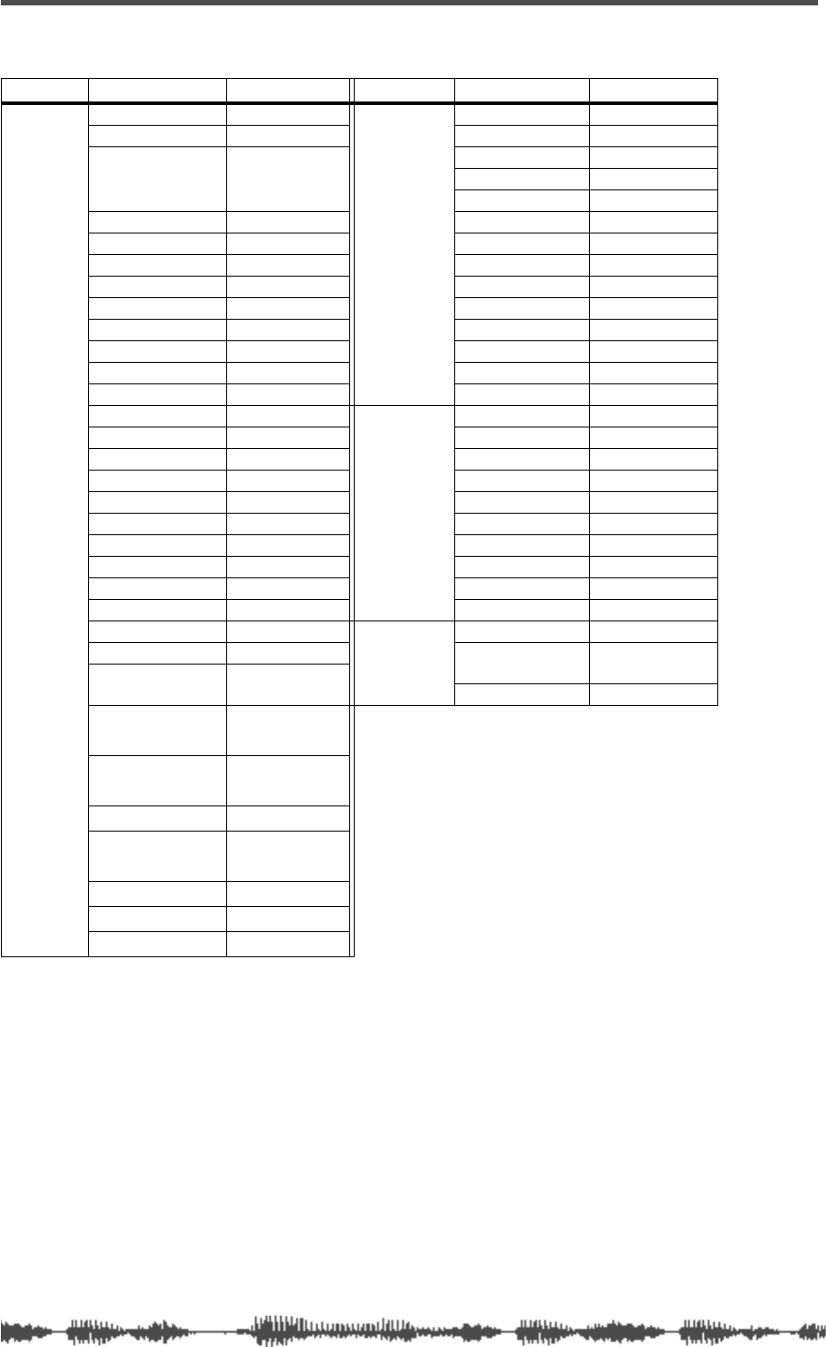
214 VM200 UserÕs Guide
P1 (Recording)
Category
Parameter
Value
Category
Parameter
Value
Channels
1–20
CH FADER –∞
MASTER
ST-BUSS MASTER 0dB
CH ON ON ST-BUSS ON ON
CH PAN Ch1–16:Center
Ch17,19:L10.0
Ch18,20:R10.0
AUX1 MASTER 0dB
AUX1 ON ON
AUX2 MASTER 0dB
AUX1 SEND –∞AUX2 ON ON
AUX2 SEND –∞AUX3 MASTER 0dB
AUX3 SEND –∞AUX3 ON ON
AUX4 SEND –∞AUX4 MASTER 0dB
EFF1 SEND –∞AUX4 ON ON
EFF2 SEND –∞EFF1 MASTER 0dB
AUX1&2 PAN Center EFF1 ON ON
AUX3&4 PAN Center EFF2 MASTER 0dB
EQ/LO Gain 0 EFF2 ON ON
EQ/LO Freq 125
SCENE
STATUS
EQ ENABLE 1–8
EQ/LO Q L-S ADD.AUX OFF
EQ/LO-MID Gain 0 AUX1 POST/PRE POST
EQ/LO-MID Freq 500 AUX2 POST/PRE POST
EQ/LO-MID Q 1.0 AUX3 POST/PRE POST
EQ/HI-MID Gain 0 AUX4 POST/PRE POST
EQ/HI-MID Freq 2.00K EFF1 POST/PRE POST
EQ/HI-MID Q 1.0 EFF2 POST/PRE POST
EQ/HI Gain 0 AUX1&2 PAIR OFF
EQ/HI Freq 8.00K AUX3&4 PAIR OFF
EQ/HI Q H-S
Others
Scene Name Recording
EQ ON ON EFFECT1 01: Normal
Large Hall
ROUTING
ST-BUSS Ch9–20 EFFECT2 38: 3D Chorus
ROUTING
REC-BUSS Ch1–8
ROUTING
DIRECT OFF
PHASE NORMAL
CH PAIR Ch1–16:off
Ch17-20:on
MUTE GROUP OFF
FADER GROUP OFF
S/P DIF IN OFF
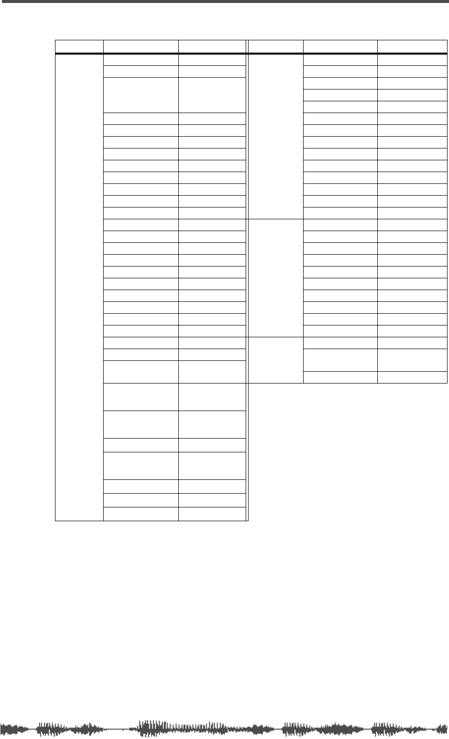
Preset Scene Parameters
VM200 UserÕs Guide 215
P2 (Mix_Down)
Category
Parameter
Value
Category
Parameter
Value
Channels
1–20
CH FADER –∞
MASTER
ST-BUSS MASTER 0dB
CH ON ON ST-BUSS ON ON
CH PAN Ch1–16:Center
Ch17,19:L10.0
Ch18,20:R10.0
AUX1 MASTER 0dB
AUX1 ON ON
AUX2 MASTER 0dB
AUX1 SEND –∞AUX2 ON ON
AUX2 SEND –∞AUX3 MASTER 0dB
AUX3 SEND –∞AUX3 ON ON
AUX4 SEND –∞AUX4 MASTER 0dB
EFF1 SEND –∞AUX4 ON ON
EFF2 SEND –∞EFF1 MASTER 0dB
AUX1&2 PAN Center EFF1 ON ON
AUX3&4 PAN Center EFF2 MASTER 0dB
EQ/LO Gain 0 EFF2 ON ON
EQ/LO Freq 125
SCENE
STATUS
EQ ENABLE 9–16
EQ/LO Q L-S ADD.AUX ON
EQ/LO-MID Gain 0 AUX1 POST/PRE POST
EQ/LO-MID Freq 500 AUX2 POST/PRE POST
EQ/LO-MID Q 1.0 AUX3 POST/PRE POST
EQ/HI-MID Gain 0 AUX4 POST/PRE POST
EQ/HI-MID Freq 2.00K EFF1 POST/PRE POST
EQ/HI-MID Q 1.0 EFF2 POST/PRE POST
EQ/HI Gain 0 AUX1&2 PAIR OFF
EQ/HI Freq 8.00K AUX3&4 PAIR OFF
EQ/HI Q H-S
Others
Scene Name Mix_Down
EQ ON ON EFFECT1 01: Normal
Large Hall
ROUTING
ST-BUSS All channels EFFECT2 38: 3D Chorus
ROUTING
REC-BUSS OFF
ROUTING
DIRECT OFF
PHASE NORMAL
CH PAIR Ch1–16:off
Ch17-20:on
MUTE GROUP OFF
FADER GROUP OFF
S/P DIF IN OFF

216 VM200 User’s Guide
MIDI In/Out Data
Format
1.
CHANGE MESSAGE
1-1.
NOTE OFF (8n)
NOTE OFF messages are not received or
transmitted.
1-2.
NOTE ON (9n)
NOTE ON messages are not received or
transmitted.
1-3.
CONTROL CHANGE (Bn)
<Reception>
Control Change messages are received only
when [CONTROL CHANGE RX] is set to ON
and the receive channel [RX CH] matches. If
[RX CH] is set to OMNI, the message is
received regardless of which channel is receiv-
ing.
Control Change messages are “echoed” when
[ECHO] is set to ON.
The parameters are controlled based on the
settings selected by [CONTROL CHANGE
TABLE].
If the messages are received while the [CTL
TABLE] setting page is displayed, the cursor
automatically moves to the corresponding
Control Change number.
<Transmission>
Control Change messages are transmitted on
the channel set by [TX CH] when you operate
the or item assigned in the table selected by
[CONTROL CHANGE TABLE] and when
[CONTROL CHANGE TX] is set to ON.
If the same item is assigned to multiple Con-
trol numbers, the smallest Control number
will be transmitted.
STATUS 1011nnnn Bn Control Change
DATA
0cccccccc cc
Control No. (0–95, 102–119)
9vvvvvvvv vv Control Value (0–127)
1-4.
PROGRAM CHANGE (Bn)
<Reception>
Program Change messages are received only
when [PROGRAM CHANGE RX] is set to ON
and the receive channel [RX CH] matches. If
[RX CH] is set to OMNI, the message is
received regardless of which channel is receiv-
ing.
Program Change messages are “echoed” when
[ECHO] is set to ON.
A scene is recalled according to the settings
selected by [PROGRAM CHANGE TABLE].
If the messages are received while the [PGM
TABLE] setting page is displayed, the cursor
automatically moves to the corresponding
PGM number.
<Transmission>
Program Change messages are transmitted on
the channel set by [TX CH] when you recall a
scene assigned in the table selected by [PRO-
GRAM CHANGE TABLE] and when [PRO-
GRAM CHANGE TX] is set to ON.
If the same scene is assigned to multiple Pro-
gram numbers, the smallest Program number
will be transmitted.
STATUS 1100nnnn Cn Program Change
DATA
0nnnnnnn nn
Program No. (0–127)
2.
EXCLUSIVE MESSAGE (F0–F7)
2-1.
MOTION CONTROL STATE (MCS
MMC STOP/PLAY/FOR-
WARD/REWIND/
RECORD/PAUSE
<Transmission>
Operating the key in the [MMC SEND] page
will transmit these messages.
Use [Dev ID.] to specify the destination.
STATUS 11110000 F0 System Exclusive Message
ID No. 01111111 7F Real Time System Exclusive
Device ID0ddddddd dd
Destination (00–7E, 7F:all call)
Command 00000110 06 MMC sub-id
0ccccccc cc Command String
[1]: Stop
[2]: Play
[4]: Fast Forward
[5]: Rewind
[6]: Record Strobe
[9]: Pause
EOX 11110111 F7 End Of Exclusive
2-2.
MOTION CONTROL PROCESS (MCP)
MMC LOCATE (target)
<Transmission>
Operating the key in the [MMC SEND] page
will transmit these messages.
Use [Dev ID] to specify the destination.
STATUS 11110000 F0 System Exclusive Message
ID No. 01111111 7F Real Time System Exclusive
Device ID0ddddddd dd
Destination (00–7E, 7F:all call)
Command 00000110 06 MMC sub-id
01000100 44 Locate
00000110 06 byte count
00000001 01 “target” sub command
0hhhhhhh hh hour
0mmmmmmm
mm minute
0ssssss ss second
0fffffff ff frame
0sssssss ss sub frame (only ‘0’)
EOX 11110111 F7 End Of Exclusive
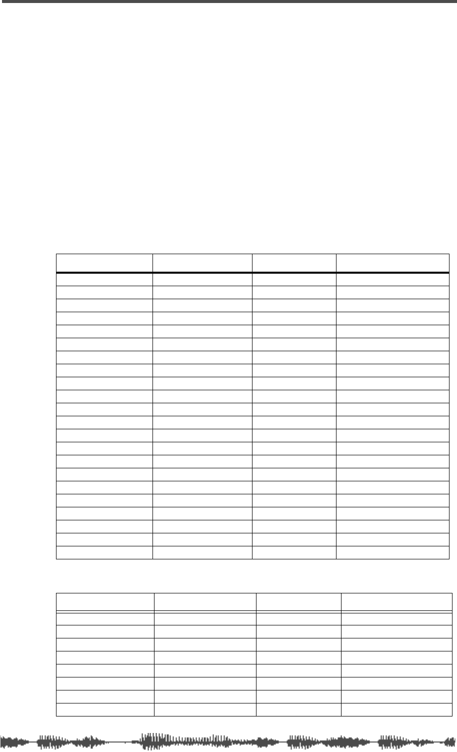
MIDI In/Out Data Format
VM200 User’s Guide 217
3.
FOSTEX EXCLUSIVE MESSAGE
<Reception>
Fostex Exclusive messages are received when [SYSTEM EX. Tx&Rx] is set to ON and the Rx
channel matches the channel of [Dev ID].
When the VM200 receives the System Exclusive message, the specified parameter will be
changed immediately.
When the VM200 receives the Parameter Request message, the corresponding parameter set-
ting will be transmitted immediately.
<Transmission>
Fostex Exclusive messages are transmitted if the Tx channel matches the channel of [Dev ID]
and when you operate the key while [SYSTEM EX. Tx&Rx] is ON.
In response to the Parameter Request messages, VM200 transmits the parameter settings if
the Tx channel matches the channel of [Dev ID].
F0 51 <Device Id>Sub Id> <Data> F7
Command List
Setup Command
Channel/Buss Command
Command Request Status
Master Clock 18,10 <master clock> 28,10 38,10 <master clock>
Fs 18,11 <fs> 28,11 38,11 <fs>
Current Scene Name 18,20 <Name..> 28,20 38,20 <Name..>
Scene Recall 18,22 <SceneNo>
Scene Store 18,23 <SceneNo>
Rcl Safe – Fader 18,28,11 <OnOff> 28,28,11 38,28,11 <OnOff>
Rcl Safe – Pan 18,28,12 <OnOff> 28,28,12 38,28,12 <OnOff>
Rcl Safe – Routing 18,28,30,7f <OnOff> 28,28,30,7f 38,28,30,7f <OnOff>
Rcl Safe – Aux Send Level 18,28,41 <AuxId> <OnOff> 28,28,41 <AuxId> 38,28,41 <AuxId> <OnOff>
Rcl Safe – Eff Send Level 18,28,49 <EffId> <OnOff> 28,28,49 <EffId> 38,28,49 <EffId> <OnOff>
Rcl Safe – Eq On 18,28,50,7f <OnOff> 28,28,50,7f 38,28,50,7f <OnOff>
Rcl Safe – Eq 18,28,5f <OnOff> 28,28,5f 38,28,5f <OnOff>
Eq Enable Ch 18,30 <EqEna> 28,30 38,30 <EqEna>
Add Aux Mode 18,31 <OnOff> 28,31 38,31 <OnOff>
Mon Sel 18,40 <MonSel> 28,40 38,40 <MonSel>
Solo Mode 18,42 <SoloMode> 28,42 38,42 <SoloMode>
Solo Key Mode 18,43 <SoloKeyMode> 28,43 38,43 <SoloKeyMode>
Motor OnOff 18,50 <OnOff> 28,50 38,50 <OnOff>
Power On Recall 18,51 <SceneNo> 28,51 38,51 <SceneNo>
Cascade 18,52 <Cascade> 28,52 38,52 <Cascade>
Memory Backup 18,60 <MemId>
Smoothing 18,32<Mode>f7 28,32,17 38,32<mode>f7
Command Request Status
ST Buss – Ch On 19,01,10 <OnOff> 29,01,10 39,01,10 <OnOff>
ST Buss – Master Fader 19,01,11 <Vol> 29,01,11 39,01,11 <Vol>
ST Buss – Solo 19,01,19 <OnOff> 29,01,19 39,01,19 <OnOff>
REC Buss – Master Level 19,02,11 <Vol> 29,02,11 39,02,11 <Vol>
REC Buss – Solo 19,02,19 <OnOff> 29,02,19 39,02,19 <Vol>
AUX Buss – Ch On 19,05 <AuxId> 10 <OnOff> 29,05 <AuxId> 10 39,05 <AuxId> 10 <OnOff>
AUX Buss – Master Fader 19,05 <AuxId> 11 <Vol> 29,05 <AuxId> 11 39,05 <AuxId> 11 <Vol>
AUX Buss – Solo 19,05 <AuxId> 19 <OnOff> 29,05 <AuxId> 19 39,05 <AuxId> 19 <OnOff>
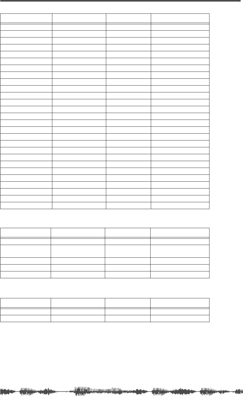
218
VM200 User’s Guide
Effects Command
Remote Command
EFF Buss – Ch On 19,06 <EffId> 10 <OnOff> 29,06 <EffId> 10 39,06 <EffId> 10 <OnOff>
EFF Buss – Master Fader 19,06 <EffId> 11 <Vol> 29,06 <EffId> 11 39,06 <EffId> 11 <Vol>
EFF Buss – Solo 19,06 <EffId> 19 <OnOff> 29,06 <EffId> 19 39,06 <EffId> 19 <OnOff>
CH1-20 – Ch On 19,10 <Ch> 10 <OnOff> 29,10 <Ch> 10 39,10 <Ch> 10 <OnOff>
CH1-20 – Ch Fader 19,10 <Ch> 11 <Vol> 29,10 <Ch> 11 39,10 <Ch> 11 <Vol>
CH1-20 – Ch Pan 19,10 <Ch> 12 <Pan> 29,10 <Ch> 12 39,10 <Ch> 12 <Pan>
CH1-20 – Ch Solo 19,10 <Ch> 19 <OnOff> 29,10 <Ch> 19 39,10 <Ch> 19 <OnOff>
CH1-20 – Phase 19,10 <Ch> 21 <Phase> 29,10 <Ch> 21 39,10 <Ch> 21 <Phase>
CH1-20 – S/P DIF IN 19,10 <Ch> 26 <OnOff> 29,10 <Ch> 26 39,10 <Ch> 26 <OnOff>
CH1-20 – Rout:ST Buss 19,10 <Ch> 30 <OnOff> 29,10 <Ch> 30 39,10 <Ch> 30 <OnOff>
CH1-20 – Rout:Rec Buss 19,10 <Ch> 31 <OnOff> 29,10 <Ch> 31 39,10 <Ch> 31 <OnOff>
CH1-20 – Rout:Adat Dir. 19,10 <Ch> 33 <OnOff> 29,10 <Ch> 33 39,10 <Ch> 33 <OnOff>
CH1-20 – Aux Send Level
19,10 <Ch> 41 <AuxId> <Vol>
29,10 <Ch> 41<AuxId> 39,10 <Ch> 41 <AuxId> <Vol>
CH1-20 – Aux Post/Pre
19,10 <Ch> 43 <AuxId> <Post/Pre>
29,10 <Ch> 43<AuxId>
39,10 <Ch> 43 <AuxId><Post/Pre>
CH1-20 – Eff Send Level
19,10 <Ch> 49 <EffId> <Vol>
29,10 <Ch> 49<EffId> 39,10 <Ch> 49 <EffId> <Vol>
CH1-20 – Eff Post/Pre
19,10 <Ch> 4b <EffId> <Post/Pre>
29,10 <Ch> 4b<EffId>
39,10 <Ch> 4b <EffId><Post/Pre>
CH1-20 – Eq On
19,10 <Ch> 50 <Band><OnOff>
29,10 <Ch> 50 <Band> 39,10 <Ch>50 <Band><OnOff>
CH1-20 – Eq Type(Q)
19,10 <Ch> 51 <Band> <Type>
29,10 <Ch> 51 <Band> 39,10 <Ch> 51 <Band><Type>
CH1-20 – Eq Gain
19,10 <Ch> 52 <Band> <Gain>
29,10 <Ch> 52 <Band> 39,10 <Ch> 52 <Band><Gain>
CH1-20 – Eq Freq.
19,10 <Ch> 53 <Band> <Freq>
29,10 <Ch> 53 <Band> 39,10 <Ch> 53 <Band><Freq>
CH1-20 – Eq Lib Recall
19,10 <Ch> 5e <LibNo>
CH1-20 – Eq Lib Store
19,10 <Ch> 5f <LibNo> <Name..>
CH1-20 – Ch Pair 19,10 <Ch> 70 <OnOff> 29,10 <Ch> 70 39,10 <Ch> 70 <OnOff>
Ch1-20 – Fader Group 19,10 <Ch> 71 <Grp> 29,10 <Ch> 71 39,10 <Ch> 71 <Grp>
CH1-20 – Mute Group 19,10 <Ch> 72 <Grp> 29,10 <Ch> 72 39,10 <Ch> 72 <Grp>
CH1-20 – Ch Solo Safe 19,10 <Ch> 73 <OnOff> 29,10 <Ch> 73 39,10 <Ch> 73 <OnOff>
CH1-20 – Ch Recall Safe 19,10 <Ch> 74 <OnOff> 29,10 <Ch> 74 39,10 <Ch> 74 <OnOff>
Command Request Status
Eff Type 1a <EffId> 10 <Type> 2a <EffId> 10 3a <EffId> 10 <Type>
Eff Parameter 1a <EffId> 11 <ParamNo>
<Val-L> <Val-H>
2a <EffId> 11
<ParamNo>
3a <EffId> 11 <ParamNo>
<Val-L> <Val-H>
Eff Name 1a <EffId> 70 <Name..> 2a <EffId> 70 3a <EffId> 70 <Name..>
Eff Lib Recall 1a <EffId> 72 <LibNo>
Eff Lib Store 1a <EffId> 73 <LibNo>
Command Request Status
Key Remote 1f, 01 <KeyId> <OnOff>
Encoder Remote 1f, 02 <EncId> <EncVal>
Command Request Status

MIDI In/Out Data Format
VM200 User’s Guide 219
Command Details
Setup Commands
<< Master Clock>>
command: F0 51 <DevId> 18 10 <MasterClock> F7.
request: F0 51 <DevId> 28 10 F7.
status: F0 51 <DevId> 38 10 <MasterClock> F7.
<MasterClock> 0:int 1:adat 2:spdif 3:word
<< Fs >>
command: F0 51 <DevId> 18 11 <Fs> F7.
request: F0 51 <DevId> 28 11 F7.
status: F0 51 <DevId> 38 11 <Fs> F7.
<Fs> 0:44.1k 1:48k
<< Current Scene Name >>
command: F0 51 <DevId> 18 20 <Name..> F7.
request: F0 51 <DevId> 28 20 F7.
status: F0 51 <DevId> 38 20 <Name..> F7.
<Name..> ASCII Character(max 9byte).
<< Scene Recall>>
command: F0 51 <DevId> 18 22 <SceneNo> F7.
<SceneNo> 00–99:User scene, 100–102:Preset scene.
<< Scene Store >>
command: F0 51 <DevId> 18 23 <SceneNo> F7.
<SceneNo> 00..99: user scene.
<< Rcl Safe – Fader >>
command: F0 51 <DevId> 18 28 11 <OnOff> F7.
request: F0 51 <DevId> 28 28 11 F7.
status: F0 51 <DevId> 38 28 11 <OnOff> F7.
<OnOff> 0:off 1:on.
<< Rcl Safe – Pan >>
command: F0 51 <DevId> 18 28 12 <OnOff> F7.
request: F0 51 <DevId> 28 28 12 F7.
status: F0 51 <DevId> 38 28 12 <OnOff> F7.
<OnOff> 0:off 1:on.
<< Rcl Safe – Routing >>
command: f0 51 <DevId> 18 28 30 7f <OnOff> f7.
request: f0 51 <DevId> 28 28 30 7f f7.
status: f0 51 <DevId> 38 28 30 7f <OnOff> f7.
<OnOff> 0:off 1:on.
<< Rcl Safe – Aux Send Level >>
command:
f0 51 <DevId> 18 28 41 <AuxId> <OnOff> f7.
request: f0 51 <DevId> 28 28 41 <AuxId> f7.
status:
f0 51 <DevId> 38 28 41 <AuxId> <OnOff> f7.
<AuxId> 01:aux1 02:aux2 03:aux3 04:aux4 7f:all_aux
<OnOff> 0:off 1:on.
<< Rcl Safe – Eff Send Level >>
command:
f0 51 <DevId> 18 28 49 <EffId> <OnOff> f7.
request: f0 51 <DevId> 28 28 49 <EffId> f7.
status:
f0 51 <DevId> 38 28 49 <EffId> <OnOff> f7.
<EffId> 01:eff1 02:eff2 7f:all_eff
<OnOff> 0:off 1:on.
<< Rcl Safe – Eq On >>
command: f0 51 <DevId> 18 28 50 7f <OnOff> f7.
request: f0 51 <DevId> 28 28 50 7f f7.
status: f0 51 <DevId> 38 28 50 7f <OnOff> f7.
<OnOff> 0:off 1:on.
<< Rcl Safe – Eq >>
command: f0 51 <DevId> 18 28 5f <OnOff> f7.
request: f0 51 <DevId> 28 28 5f f7.
status: f0 51 <DevId> 38 28 5f <OnOff> f7.
<OnOff> 0:off 1:on.
<< Eq Enable Ch >>
command: f0 51 <DevId> 18 30 <EqEna> f7.
request: f0 51 <DevId> 28 30 f7.
status: f0 51 <DevId> 38 30 <EqEna> f7.
<EqEna> 00:1to8 01:8to16 02:1to16
<< Add Aux Mode >>
command: f0 51 <DevId> 18 31 <OnOff> f7.
request: f0 51 <DevId> 28 31 f7.
status: f0 51 <DevId> 38 31 <OnOff> f7.
<OnOff> 00:off 01:on
<< Smoothing >>
command: f0 51 <DevId> 18 32 <Mode> f7.
request: f0 51 <DevId> 28 32 f7.
status: f0 51 <DevId> 38 32 <Mode> f7
<Mode> 00:Level1 01:Level2
<< Mon Sel >>
command: f0 51 <DevId> 18 40 <MonSel> f7.
request: f0 51 <DevId> 28 40 f7.
status: f0 51 <DevId> 38 40 <MonSel> f7.
<MonSel>
00:ST_BUSS 01:REC_BUSS 02:AUX1 03:AUX2
04:AUX3 05:AUX4 06:EFF1 07:EFF2 08:AUX12
09:AUX34
<< Solo Mode >>
command: f0 51 <DevId> 18 42 <SoloMode> f7.
request: f0 51 <DevId> 28 42 f7.
status: f0 51 <DevId> 38 42 <SoloMode> f7.
<SoloMode>
00:PFL 02:M-SOLO (01:AFL does not apply to
VM200.
)
<< Solo Key Mode >>
command: f0 51 <DevId> 18 43 <SoloKeyMode> f7.
request: f0 51 <DevId> 28 43 f7.
status: f0 51 <DevId> 38 43 <SoloKeyMode> f7.
<SoloKeyMode> 00:latCh 01:unlatCh
<< Motor OnOff >>
command: f0 51 <DevId> 18 50 <OnOff> f7.
request: f0 51 <DevId> 28 50 f7.
status: f0 51 <DevId> 38 50 <OnOff> f7.
<OnOff> 00:off 01:on

220 VM200 User’s Guide
<< Power On Recall >>
command: f0 51 <DevId> 18 51 <SceneNo> f7.
request: f0 51 <DevId> 28 51 f7.
status: f0 51 <DevId> 38 51 <SceneNo> f7.
<SceneNo> 00–99:User scene, 100–102:Preset scene.
103:Last store secene.
<< Cascade >>
command: f0 51 <DevId> 18 52 <Cascade> f7.
request: f0 51 <DevId> 28 52 f7.
status: f0 51 <DevId> 38 52 <Cascade> f7.
<Cascade> 0:Off 1:On_A 2:On_B 3:On_C
<< Memory Backup >>
command: f0 51 <DevId> 18 60 <MemId> f7
<MemId> 1:setup(system + midi) parameters,
2:Scene Memory, 3:Eff Lib, 4:EQ Lib
Channel/Buss Commands
<< ST Buss – Ch On >>
command: f0 51 <DevId> 19 01 10 <OnOff> f7.
request: f0 51 <DevId> 29 01 10 f7.
status: f0 51 <DevId> 39 01 10 <OnOff> f7.
<OnOff> 0:off 1:on
<< ST Buss – Master Fader >>
command: f0 51 <DevId> 19 01 11 <Vol> f7.
request: f0 51 <DevId> 29 01 11 f7.
status: f0 51 <DevId> 39 01 11 <Vol> f7.
<Vol> 0 to 127.
<< ST Buss – Solo >>
command: f0 51 <DevId> 19 01 19 <OnOff> f7.
request: f0 51 <DevId> 29 01 19 f7.
status: f0 51 <DevId> 39 01 19 <OnOff> f7.
<OnOff> 0:off 1:on
<< REC Buss – Master Level >>
command: f0 51 <DevId> 19 02 11 <Vol> f7.
request: f0 51 <DevId> 29 02 11 f7.
status: f0 51 <DevId> 39 02 11 <Vol> f7.
<Vol> 0 to 127.
<< REC Buss – Solo >>
command: f0 51 <DevId> 19 02 19 <OnOff> f7.
request: f0 51 <DevId> 29 02 19 f7.
status: f0 51 <DevId> 39 02 19 <OnOff> f7.
<OnOff> 0:off 1:on
<< AUX Buss – Ch On >>
command:
f0 51 <DevId> 19 05 <AuxId> 10 <OnOff> f7.
request: f0 51 <DevId> 29 05 <AuxId> 10 f7.
status:
f0 51 <DevId> 39 05 <AuxId> 10 <OnOff> f7.
<AuxId> 1:aux1 2:aux2 3:aux3 4:aux4 0x7f:all_aux
<OnOff> 0:off 1:on
<< AUX Buss – Master Fader >>
command: f0 51 <DevId> 19 05 <AuxId> 11 <Vol> f7.
request: f0 51 <DevId> 29 05 <AuxId> 11 f7.
status: f0 51 <DevId> 39 05 <AuxId> 11 <Vol> f7.
<AuxId> 1:aux1 2:aux2 3:aux3 4:aux4 0x7f:all_aux
<Vol> 0 to 127
<< AUX Buss – Solo >>
command:
f0 51 <DevId> 19 05 <AuxId> 19 <OnOff> f7.
request: f0 51 <DevId> 29 05 <AuxId> 19 f7.
status:
f0 51 <DevId> 39 05 <AuxId> 19 <OnOff> f7.
<AuxId> 1:aux1 2:aux2 3:aux3 4:aux4 0x7f:all_aux
<OnOff> 0:off 1:on
<< EFF Buss – Ch On >>
command:
f0 51 <DevId> 19 06 <EffId> 10 <OnOff> f7.
request: f0 51 <DevId> 29 06 <EffId> 10 f7.
status:
f0 51 <DevId> 39 06 <EffId> 10 <OnOff> f7.
<EffId> 1:eff1 2:eff2 0x7f:all_eff
<OnOff> 0:off 1:on
<< EFF Buss – Master Fader >>
command: f0 51 <DevId> 19 06 <EffId> 11 <Vol> f7.
request: f0 51 <DevId> 29 06 <EffId> 11 f7.
status: f0 51 <DevId> 39 06 <EffId> 11 <Vol> f7.
<EffId> 1:eff1 2:eff2 0x7f:all_eff
<Vol> 0 to 127
<< EFF Buss – Solo >>
command:
f0 51 <DevId> 19 06 <EffId> 19 <OnOff> f7.
request: f0 51 <DevId> 29 06 <EffId> 19 f7.
status:
f0 51 <DevId> 39 06 <EffId> 19 <OnOff> f7.
<EffId> 1:eff1 2:eff2 0x7f:all_eff
<OnOff> 0:off 1:on
<< CH1-20 – Ch On >>
command: f0 51 <DevId> 19 10 <Ch> 10 <OnOff> f7.
request: f0 51 <DevId> 29 10 <Ch> 10 f7.
status: f0 51 <DevId> 39 10 <Ch> 10 <OnOff> f7.
<Ch> 1-20:Ch 0x7f:all_Ch
<OnOff> 0:off 1:on
<< CH1-20 – Ch Fader >>
command: f0 51 <DevId> 19 10 <Ch> 11 <Vol> f7.
request: f0 51 <DevId> 29 10 <Ch> 11 f7.
status: f0 51 <DevId> 39 10 <Ch> 11 <Vol> f7.
<Ch> 1-20:Ch 0x7f:All
<Vol> 0:off 1:on
<< CH1-20 – Ch Pan >>
command: f0 51 <DevId> 19 10 <Ch> 12 <Pan> f7.
request: f0 51 <DevId> 29 10 <Ch> 12 f7.
status: f0 51 <DevId> 39 10 <Ch> 12 <Pan> f7.
<Ch> 1-20:Ch 0x7f:all_Ch
<Pan> 0 to 40 (0:L - 20:Center - 40:R)
<< CH1-20 – Ch Solo >>
command: f0 51 <DevId> 19 10 <Ch> 19 <OnOff> f7.
request: f0 51 <DevId> 29 10 <Ch> 19 f7.
status: f0 51 <DevId> 39 10 <Ch> 19 <OnOff> f7.

MIDI In/Out Data Format
VM200 User’s Guide
221
<Ch> 1-20:Ch 0x7f:All
<OnOff> 0:off 1:on
<< CH1-20 – Phase >>
command: f0 51 <DevId> 19 10 <Ch> 21 <Phase> f7.
request: f0 51 <DevId> 29 10 <Ch> 21 f7.
status: f0 51 <DevId> 39 10 <Ch> 21 <Phase> f7.
<Ch> 1-20:Ch 0x7f:all_Ch
<Phase> 0:Nor. 1:Inv.
<< CH1-20 – S/P DIF In>>
command: f0 51 <DevId> 19 10 <Ch> 26 <OnOff> f7.
request: f0 51 <DevId> 29 10 <Ch> 26 f7.
status: f0 51 <DevId> 39 10 <Ch> 26 <OnOff> f7.
<Ch> 1-20:Ch 0x7f:all_Ch
<OnOff> 0:off 1:on
<< CH1-20 – Rout:ST Buss >>
command: f0 51 <DevId> 19 10 <Ch> 30 <OnOff> f7.
request: f0 51 <DevId> 29 10 <Ch> 30 f7.
status: f0 51 <DevId> 39 10 <Ch> 30 <OnOff> f7.
<Ch> 1-20:Ch 0x7f:all_Ch
<OnOff> 0:off 1:on
<< CH1-20 – Rout:REC Buss >>
command: f0 51 <DevId> 19 10 <Ch> 31 <OnOff> f7.
request: f0 51 <DevId> 29 10 <Ch> 31 f7.
status: f0 51 <DevId> 39 10 <Ch> 31 <OnOff> f7.
<Ch> 1-20:Ch 0x7f:all_Ch
<OnOff> 0:off 1:on
<< CH1-20 : Adat Direct >>
command: f0 51 <DevId> 19 10 <Ch> 33 <OnOff> f7.
request: f0 51 <DevId> 29 10 <Ch> 33 f7.
status: f0 51 <DevId> 39 10 <Ch> 33 <OnOff> f7.
<Ch> 1-8:Ch 0x7f:all_Ch
<OnOff> 0:off 1:on
<< CH1-20 – Aux Send Level >>
command:
f0 51 <DevId> 19 10 <Ch> 41 <AuxId> <Vol> f7.
request: f0 51 <DevId> 29 10 <Ch> 41 <AuxId> f7.
status:
f0 51 <DevId> 39 10 <Ch> 41 <AuxId> <Vol> f7.
<Ch> 1-20:Ch 0x7f:all_Ch
<AuxId> 1:aux1 2:aux2 3:aux3 4:aux4 0x7f:all_aux
<Vol> 0-127:Vol
<< CH1-20 – Aux Post/Pre >>
command: f0 51 <DevId> 19 10 <Ch> 43 <AuxId>
<Post/Pre> f7.
request: f0 51 <DevId> 29 10 <Ch> 43 <AuxId> f7.
status: f0 51 <DevId> 39 10 <Ch> 43 <AuxId>
<Post/Pre> f7.
<Ch> 0x7f:all_Ch
<AuxId> 1:aux1 2:aux2 3:aux3 4:aux4 0x7f:all_aux
<Post/Pre> 0:post 1:pre
<< CH1-20 – Eff Send Level >>
command:
f0 51 <DevId> 19 10 <Ch> 49 <EffId> <Vol> f7.
request: f0 51 <DevId> 29 10 <Ch> 49 <EffId> f7.
status:
f0 51 <DevId> 39 10 <Ch> 49 <EffId> <Vol> f7.
<Ch> 1-20:Ch 0x7f:all_Ch
<EffId> 1:eff1 2:eff2 0x7f:all_eff
<Vol> 0-127:Volume
<< CH1-20 – Eff Post/Pre >>
command: f0 51 <DevId> 19 10 <Ch> 4b <EffId>
<Post/Pre> f7.
request: f0 51 <DevId> 29 10 <Ch> 4b <EffId> f7.
status: f0 51 <DevId> 39 10 <Ch> 4b <EffId>
<Post/Pre> f7.
<Ch> 0x7f:all_Ch
<EffId> 1:eff1 2:eff2 0x7f:all_eff
<Post/Pre> 0:post 1:pre
<< CH1-20 – Eq On >>
command: f0 51 <DevId> 19 10 <Ch> 50 <Band>
<OnOff> f7
request: f0 51 <DevId> 29 10 <Ch> 50 <Band> f7
status: f0 51 <DevId> 39 10 <Ch> 50 <Band>
<OnOff> f7
<Ch> 1-16:Ch 0x7f:all_Ch
<Band> 0x7f:all Band.
<OnOff> 0:off 1:on
<< CH1-20 – Eq Type(Q) >>
command:
f0 51 <DevId> 19 10 <Ch> 51 <Band> <Type> f7
request: f0 51 <DevId> 29 10 <Ch> 51 <Band> f7
status:
f0 51 <DevId> 39 10 <Ch> 51 <Band> <Type> f7
<Ch> 1-16:Ch 0x7f:all_Ch
<Band> 1:L 2:LM 3:HM 4:H 0x7f:All_Band.
<Type> 0:Hi/Lo_pass 1:Shelving 2-46:Parmetric_Q
<< CH1-20 – Eq Gain >>
command:
f0 51 <DevId> 19 10 <Ch> 52 <Band> <Gain> f7
request: f0 51 <DevId> 29 10 <Ch> 52 <Band> f7
status:
f0 51 <DevId> 39 10 <Ch> 52 <Band> <Gain> f7
<Ch> 1-16:Ch 0x7f:all_Ch
<Band> 1:L 2:LM 3:HM 4:H 0x7f:All_Band.
<Gain> 0-72:gain (36:0dB)
<< CH1-20 – Eq Freq >>
command: f0 51 <DevId> 19 10 <Ch> 53 <Band> <fL>
<fH> f7
request: f0 51 <DevId> 29 10 <Ch> 53 <Band> f7
status: f0 51 <DevId> 39 10 <Ch> 53 <Band> <fL>
<fH> f7
<Ch> 1-16:Ch 0x7f:all_Ch
<Band> 1:L 2:LM 3:HM 4:H 0x7f:all_Band.
<fL>(lower 7bit) + <fH>(upper 7bit) 0-239:F step.
<< CH1-20 – Eq Lib Recall >>
command: f0 51 <DevId> 19 10 <Ch> 5e <LibNo> f7
<Ch> 1-16:Ch 0x7f:All
<LibNo> 0-99:Eq lib number.

222
VM200 User’s Guide
<< CH1-20 – Eq Lib Store >>
command: f0 51 <DevId> 19 10 <Ch> 5f <LibNo>
<Name..> f7
<Ch> 1-16:Ch 0x7f:All
<LibNo> 50-99:Eq lib number.
<Name..> Max 9byte lib Name ascii string.
<< CH1-20 – Ch Pair >>
command: f0 51 <DevId> 19 10 <Ch> 70 <OnOff> f7
request: f0 51 <DevId> 29 10 <Ch> 70 f7
status: f0 51 <DevId> 39 10 <Ch> 70 <OnOff> f7
<Ch> 1-20:Ch 0x7f:all_Ch
<OnOff> 0:off 1:on
<< CH1-20 – Fader Group >>
command: f0 51 <DevId> 19 10 <Ch> 71 <Grp> f7
request: f0 51 <DevId> 29 10 <Ch> 71 f7
status: f0 51 <DevId> 39 10 <Ch> 71 <Grp> f7
<Ch> 1-20:Ch 0x7f:all_Ch
<Grp> 0:off 1:A 2:B 3:C
<< CH1-20 – Mute Group >>
command: f0 51 <DevId> 19 10 <Ch> 72 <Grp> f7
request: f0 51 <DevId> 29 10 <Ch> 72 f7
status: f0 51 <DevId> 39 10 <Ch> 72 <Grp> f7
<Ch> 1-20:Ch 0x7f:all_Ch
<Grp> 0:off 1:A 2:B 3:C
<< CH1-20 – Ch Solo Safe >>
command: f0 51 <DevId> 19 10 <Ch> 73 <OnOff> f7
request: f0 51 <DevId> 29 10 <Ch> 73 f7
status: f0 51 <DevId> 39 10 <Ch> 73 <OnOff> f7
<Ch> 1-20:Ch 0x7f:all_Ch
<OnOff> 0:off 1:on
<< CH1-20 – Ch Recall Safe >>
command: f0 51 <DevId> 19 10 <Ch> 74 <OnOff> f7
request: f0 51 <DevId> 29 10 <Ch> 74 f7
status: f0 51 <DevId> 39 10 <Ch> 74 <OnOff> f7
<Ch> 1-20:Ch 0x7f:all_Ch
<OnOff> 0:off 1:on
Effects Commands
<< Eff Type >>
command: f0 51 <DevId> 1a <EffId> 10 <Type> f7
request: f0 51 <DevId> 2a <EffId> 10 f7
command f0 51 <DevId> 3a <EffId> 10 <Type> f7
<EffId> 1:eff1 2:eff2 0x7f:all_Ch
<Type> 0 to (EFFTYP_END - 1)
<< Eff Parameter >>
command: f0 51 <DevId> 1a <EffId> 11 <ParamNo>
<valL> <valH> f7
request: f0 51 <DevId> 2a <EffId> 11 <ParamNo> f7
command: f0 51 <DevId> 3a <EffId> 11 <ParamNo> f7
<EffId> 1:eff1 2:eff2 0x7f:all_Ch
<ParamNo> 1 to 12 or 0x7f:all_params.
<ValL> + <ValH>: 14bit parameter value.
<< Eff Name >>
command: f0 51 <DevId> 1a <EffId> 70 <Name..> f7
request: f0 51 <DevId> 2a <EffId> 70 f7
status: f0 51 <DevId> 3a <EffId> 70 <Name..> f7
<EffId> 1:eff1 2:eff2 0x7f:all_eff
<Name..> Max 9byte lib Name ascii string.
<< Eff Lib Recall >>
command: f0 51 <DevId> 1a <EffId> 72 <LibNo> f7
<EffId> 1:eff1 2:eff2 0x7f:all_eff
<LibNo> 0 to 99 eff lib number.
<< Eff Lib Store >>
command: f0 51 <DevId> 1a <EffId> 73 <LibNo> f7
<EffId> 1:eff1 2:eff2
<LibNo> 50 to 99 eff lib number.
Remote Commands
<< Key Remote >>
command: f0 51 <DevId> 1f 01 <KeyId> <OnOff> f7
<KeyId> 01-08:[Channel]On, 09:[Master]On,
11-18:[Channel]Solo, 19:[Master]Solo
1a:[Rec Buss]Solo, 21-28:[Channel]EQ Edit
31:[Fader Mode]Channel,
32-35:[Fader Mode]Aux1-4,
36-37:[Fader Mode]Eff1-2
38:[Key Mode]Routing/Phase
39:[Key Mode]Pair/Group
3a:[Key Mode]Ch View
3b:[Key Mode]Channel/Meter
41:
[Current Scene Status], 42:[Setup]System
43:[Setup]Midi, 51:[Page Sel]1-8
52:[Page Sel]9-16, 53:[Page Sel]17-20
61:[Selected EQ]EQ On
62:[Selected EQ] Library Recall
63:[Selected EQ]Library Store
64:[Eff Edit]Eff1, 65:[Eff Edit]Eff2
66:[Eff Edit]Library Recall
67:[Eff Edit]Library Store
68:[Scene Memory]Recall
69:[Scene Memory]Store
71:<-/-1, 72:+1->, 73:Exit, 74:Enter
<OnOff> 0:off 1:on
<< Key Remote >>
command: f0 51 <DevId> 1f 02 <EncId> <EncVal> f7
<EncId> 01-12:Encoder (top raw from left:1-4,
bottom raw from left: 9-12), 11:Data
<EncVal> 0-3f:-64 – -1, 40-7f:+1 – +64
0–3f:variation=0x40-Val
40–7f:variation=Val-0x3f

MIDI In/Out Data Format
VM200 User’s Guide 223
4.
Bulk Dump (& Request)
<Reception>
Bulk Dump is received when [BLK DMP EQ.] is set to ON and when [RX CH] and DEVICE No.
match.
The received Bulk Dump is immediately written into the specified memory.
When the VM200 receives the Bulk Dump Request, it immediately transmits Bulk Dump.
<Transmission>
Bulk Dump is transmitted on the channel specified by [TX CH] when you operate the key in the
[BULK DUMP] page.
In response to Bulk Dump Request, Bulk Dump is sent on the channel specified by [RX CH].
4-1.
Bulk Dump Request
<< Setup Bulk Dump Request >>
f0 51 <DevId> 2B ’V’ ’M’ ’2’ ’0’ ’0’ ’A’ 01 <Item> f7
<Item> 01:System, 02:Midi, 03:Locate, 127:All Setup
<< Scene Memory Bulk Dump Request >>
f0 51 <DevId> 2B ’V’ ’M’ ’2’ ’0’ ’0’ ’A’ 02 <MemNo> f7
<MemNo> 0: Edit Buffer, 1 – 100: UserMemory, 127: All User Memory
<< Eff Library Bulk Dump Request >>
f0 51 <DevId> 2B ’V’ ’M’ ’2’ ’0’ ’0’ ’A’ 03 <LibNo> f7
<LibNo> 50 – 99: User Library, 127: All User Library
<< Eq Library Bulk Dump Request >>
f0 51 <DevId> 2B ’V’ ’M’ ’2’ ’0’ ’0’ ’A’ 04 <LibNo> f7
<LibNo> 50 – 99: User Library, 127: All User Library
<< PGM Table Bulk Dump Request >>
f0 51 <DevId> 2B ’V’ ’M’ ’2’ ’0’ ’0’ ’A’ 05 00 f7
<< CTL Table Bulk Dump Request >>
f0 51 <DevId> 2B ’V’ ’M’ ’2’ ’0’ ’0’ ’A’ 06 00 f7
4-2.
BULK DUMP OUT FORMAT
<< Setup Bulk Dump Format >>
f0 51 <DevId> 3B <Byte Count L> <Byte Count H> ’V’ ’M’ ’2’ ’0’ ’0’ ’A’ 01 <Item>
<Data> --- <Data> <Check Sum> f7
<< Scene Memory Bulk Dump Format >>
f0 51 <DevId> 3B <Byte Count L> <Byte Count H> ’V’ ’M’ ’2’ ’0’ ’0’ ’A’ 02 <MemNo>>
<Data> --- <Data> <Check Sum> f7
<MemNo> 0: Edit Buffer, 1 – 100: UserMemory
<< Eff Library Bulk Dump Format >>
f0 51 <DevId> 3B <Byte Count L> <Byte Count H> ’V’ ’M’ ’2’ ’0’ ’0’ ’A’ 03 <LibNo>>
<Data> --- <Data> <Check Sum> f7
<LibNo> 50 – 99: User Library
<< Eq Library Bulk Dump Format >>
f0 51 <DevId> 3B <Byte Count L> <Byte Count H> ’V’ ’M’ ’2’ ’0’ ’0’ ’A’ 04 <LibNo>>
<Data> --- <Data> <Check Sum> f7
<LibNo> 50 – 99: User Library
<< PGM Table Bulk Dump Format >>
f0 51 <DevId> 3B <Byte Count L> <Byte Count H> ’V’ ’M’ ’2’ ’0’ ’0’ ’A’ 05 00
<Data> --- <Data> <Check Sum> f7
<< CTL Table Bulk Dump Format >>
f0 51 <DevId> 3B <Byte Count L> <Byte Count H> ’V’ ’M’ ’2’ ’0’ ’0’ ’A’ 06 00
<Data> --- <Data> <Check Sum> f7
* “Byte Count” is the number of bytes counted from the byte following <Byte Count> up to the
byte before <Check Sum>.
* “Check Sum” covers after <Byte Count> before <Check Sum>, with all EOR being removed.

224 VM200 User’s Guide
5.
MIDI Device Inquiry Message
The VM200 transmits Identity Reply when it receives Identity Request, if the Setup: System
EX. Tx&Rx has been turned on.
Identity Request: F0 7c <DeviceId> 06 01 f7
Identity Reply: F0 7c <DeviceId> 06 02 51 02 00 01 00 01 00 63 04 f7

MIDI Implementation Chart
VM200 User’s Guide 225
FOSTEX (Digital Recording Mixer – Internal Parameters)
MIDI Implementation Chart
Model: VM200 Version:1.0
Mode 1: OMNI ON, POLY Mode 2: OMNI ON, MONO O: Yes
Mode 3: OMNI OFF, POLY Mode 4: OMNI OFF, MONO X: No
Function... Transmitted Recognized Remarks
Basic
Channel
Default 1-16 1-16 Memorized
Changed 1-16 1-16
Mode
Default X OMNI off / OMNI on
MemorizedMessages X X
Altered ******************** X
Note
Number
XX
True voice ******************** X
Velocity Note ON X X
Note OFF X X
After
Touch
Key’s X X
Ch’s X X
Pitch Bend X X
Control
Change
0-95, 102-119 O O Assignable
Prog
Change
O 0-127 O 0-127 Assignable
True # ******************** 0-99
System Exclusive O O
System
Common
Song Pos X X
Song Sel X X
Tune X X
System
Real Time
Clock X X
Commands X X
Aux
Messages
Local ON/OFF X X
All Note Off X X
Active Sense X X
Reset X X

226
VM200 User’s Guide
Declaration of EC Directive
This equipment is compatible with the EMC Directive
(89/336/EEC) - Directive on approximation of member
nation's ordinance concerning the electromagnetic compatibil-
ity and with the Low Voltage Directive (73/23/EEC) - Directive
on approximation of member nation's ordinance concerning
electric equipment designed to be used within the specified
voltage range.
The Affect of Immunity on This Equipment
The affect of the European Specification EN50082-1 (coexist-
ence of electromagnetic waves - common immunity specifica-
tion) on this equipment are as shown below.
❑
In the electrical fast transient/burst requirements, radiate
electromagnetic field requirements and static electricity dis-
charging environment, this could be affected by generation of
noise in some cases.
Fostex Distributors List In Europe
❑
Including non-EU countries.
❑
underlined: contracted distributors (as of April 1999)
<AUSTRIA>
Name: ATEC Audio-u. Videogeraete VertriebsgesmbH.
Address: Im Winkel 5, A-2325 Velm, Austria
Tel: (+43) 2234-74004, Fax: (+43) 2234-74074
<BELGIUM>
Name: EML Sound Industries N. V.
Address: Bijvennestraat 1A, B3500 Hasselt, Belgium
Tel: (+32) 11-232355, Fax: (+32) 11-232172
<DENMARK>
Name: SC Sound ApS
ADD: Malervej 2, DK-2630 Taastrup, Denmark
Tel: (+45) 4399-8877, Fax: (+45) 4399-8077
<FINLAND>
Name: Noretron Oy Audio
Address: P.O. Box 22, FIN-02631 Espoo, Finland
Tel: (+358) 9-5259330, Fax: (+358) 9-52593352
<FRANCE>
Name: Musikengro
Address: ZAC de Folliouses, B. P. 609, 01706 Les Echets, France
Tel: (+33) 472 26 27 00, Fax: (+33) 472 26 27 01
<GERMANY>
Name: Studio sound & Music GmbH
Address: Industriestrasse 20, D-35041 Marburg, F.R. Germany
Tel: (+49) 6421-92510, Fax: (+49) 6421-925119

Fostex Distributors List In Europe
VM200 User’s Guide
227
<GREECE>
Name: Bon Studio S. A.
Address: 6 Zaimi Street, Exarchia, 106.83 Athens, Greece
Tel: (+30) 1-3809605-8, 3302059, Fax: (+30) 1-3845755
<ICELAND>
Name: I. D. elrf. electronic Ltd.
Address: ARMULA 38 108 REYKJAVIK, ICELAND
Tel: (+354) 588 5010, Fax: (+354) 588 5011
<ITALY>
Name: Recoton Italia Srl.
Address:V. 1 Maggio, N 18, 40050 Quarto Inferiore, (BO) Italy
Tel: (+39) 051-768576, Fax: (+39) 051-768336
<THE NETHERLANDS>
Name: IEMKE ROOS AUDIO B. V.
Address: Kuiperbergweg 20, 1101 AG Amsterdam, The Netherlands
Tel: (+31) 20-697-2121, Fax: (+31) 20-697-4201
<NORWAY>
Name: Siv. Ing. Benum A/S
Address: P. O. Box 145 Vinderen, 0319 Oslo 3, Norway
Tel: (+47) 22-139900, Fax: (+47) 22-148259
<PORTUGAL>
Name: Caius - Tecnologias Audio e Musica, Lda.
Address: Rua de Santa Catarina, 131 4000 Porto, Portugal
Tel: (+351) 2-2086009/2001394, Fax: (+351) 2-2054760/2087488
<SPAIN>
Name: Multitracker, S. A.
Address: C/Garcilaso No.9, Madrid 28010, Spain
Tel: (+34) 91-4470700, 91-4470898, Fax: (+34) 91-5930716
<SWEDEN>
Name: TTS Professional Television AB
Address: Kavallerivagen 24, 172 48 Sundbyberg, Sweden
Tel: (+46) 8-59798000, Fax: (+46) 8-59798001
<SWITZERLAND>
Name: Audio Bauer Pro AG
Address: Bernerstrasse-Nord 182, CH-8064 Zurich, Switzerland
Tel: (+41) 1-4323230, Fax: (+41) 1-4326558
<UK>
Name: SCV London
Address: 3A 6-24 Southgate Road, London N1 3JJ, England, UK
Tel: (+44) 171-923-1892, Fax: (+44) 171-241-3644

228 VM200 User’s Guide

VM200 User’s Guide 229
Index
A
A inputs 19, 39
A.S.P. 124
A/B Input selectors 19
A/D converters 12, 48
AC power 39, 45
ADAT 15, 40
ADAT interface 160
ADAT OUT 24, 109, 166
ADAT-compatible 40
ADD. AUX parameter 14, 24, 38, 115
Advanced Signal Processing Technology 15, 124
Alesis ADAT 14, 15, 40
amplifier 99
analog control section 19
applying effects 128
ASP 15
assigning names to programs 86
attenuators 14
AUX keys 27
AUX Sends 14, 39, 109, 115, 116
muting 118
B
B Inputs 19
balanced XLR inputs 39
bands, EQ 36, 76
block diagram 41
Bulk Dump 174, 179, 189, 223
BULK DUMP function page 23
Bulk RX parameter 179
bypassing the EQ 80
C
cascade configuration 14, 171, 174
CD players 40, 52
CH COPY function page 26, 72
CH EDIT function page 26, 49
CH PAIR function page 25
CH VIEW function page 26
CH VIEW key 24, 25
channel control 32
Channel Edit/Input 26
Channel Edit/Output 26
Channel Fader Gain Table 206
Channel Fader Mode 35
CHANNEL key 27
channel layers 16, 37, 46
Channel Pair (Ch Pair) function page 25
channel pairs 68
Channel View key 25
CHANNEL/METER key 24, 26
channels, copying settings 72
character selector box 86, 154
CHORUS 142
CHORUS-REVERB 144
clock 12
condenser microphones 39
connecting MIDI devices 175
contrast 20
Control Change 178
Control Change Assign Tables 178, 185, 211
Control Change messages 184
Control Change RX 178
Control Change TX 178
control surface illustration 18
controls, rotary 48
converters, D/A and A/D 12, 48
copying channel settings 72
copying EQ settings 90
CTL TABLE1 function page 23
CTL TABLE2 function page 23
Current Scene Status function page 80
CURRENT SCENE STATUS key 24
Current Scene Status section 24
curve, response 78
D
D/A converters 12, 48
DAT recorders 40
Data Wheel 21, 28, 29, 30, 56
default settings 198, 200
delays 126
DevID parameter 179
diagram, block 41
digital connectors 160
Display, LCD 15, 20, 49
DUAL_DELAY 141
DUAL_PITCH 143
dynamic microphones 19
dynamic range 12
E
ECHO parameter 176
EDIT indicator 149
editing effects 133
Eff Edit
function page 29
section 29
EFF LIBRARY NAME EDIT function page 135
EFF1 15, 27, 29, 124, 128
EFF2 15, 27, 29, 124, 128
effect combinations 29
Effect Library Name Edit function page 30
Effect Library Store function page 30
Effect Preset Library List 125
Effects Library 14, 29, 56, 124, 125, 133
Effects 29, 56, 124
processors 15
return, setting 128
applying 128
editing 133
multi presets 127
naming 135
panning 132
parameters 139
recalling 134
storing 135
ENTER key 21, 30
EQ 15, 28, 76
adjusting 77
bypassing 80
copying settings 90
enabling 80
recalling 84
resetting 81
storing 86
EQ COPY function page 26, 90

230 VM200 User’s Guide
EQ Edit function page 36, 54, 76
EQ EDIT keys 34, 36
EQ Frequency 209
EQ Library 15, 28, 76, 83, 86
EQ Library Name Edit function page 29, 86
EQ Library Recall function page 28, 84
EQ Library Store function page 29
EQ ON key 28
EQ Preset Library List 83
EQ Preset Library Parameters 92
EQ program titles 88
equalizer 14, 28, 36, 76
EXIT Key 21
F
Fader Gain Tables 206
FADER GROUP function page 25
Fader groups 69
Fader Mode 16, 27, 32, 35, 65
faders 16, 27, 32, 49, 153
FD-8 10
FLANGE 142
FLANGE-REVERB 145
flashing keys 22
Fostex 9910 11
Fostex Advanced Signal Processing
Technology 15, 124
Fostex FD-8 10
Fostex System Exclusive 174, 217
Fostex VR800 10, 15, 40, 164, 165, 166, 192
Frame Mode 194
Freq 54, 77
Freq control 86
frequency response 12
frequency response curve 78
function pages 22, 50
G
Gain 54, 77, 78, 86
Gain control 86
guided tour 17
H
Harmonic Feedback Algorithm 15
headphones 14, 99
High Density Logarithmic Processing 15
high-pass filter 76
HPF 76
I
initializing the VM200 198
Input Channels 1 - 4 39, 60
input channels 17–20 61
Input channels 5–8 39, 61
input channels 9-16 61
input preamps 19
inputs 12
Inputs, Channel Edit 26
Insert connectors 62
inverting phase 64
K
key 24
Key Mode section 24
keyboard 52
L
LATCH 111
LCD Display 15, 20, 49
LED Display Meter 106
LED meters 20
LED-lighted keys 51
level, stereo output 111
line-level sources 39
locate points 195
low-pass filter 76
LPF 76
M
maintenance 205
Master Fader 16, 32, 111
Master Fader Gain 207
master, word clock 163
memory, scene 148
messages
system exclusive 179
warning 202
metering levels 105
meters 105
meters, LED 20
microphones 39, 52
dynamic 19
MIDI 12, 23
MIDI connections 16
MIDI Control Change 16, 184
MIDI controllers 16, 32
MIDI devices, connecting 175
MIDI Implementaion Chart 225
MIDI IN 40
MIDI In/Out Data 216
MIDI key 23, 176
MIDI Machine Control 192
MIDI OUT 40
MIDI ports 40, 174
MIDI Program Change 16, 152, 174
MIDI studio 10
MIDI THRU 40
MIDI Transmit and Receive Channels 176
MIDI TX&R function page 23
mix scenes, storing 154
Mix Solo 35, 99, 101, 102
MMC (MIDI Machine Control) 16, 192
MMC mode 25
modes, Fader 16
modulation effects 126
MON SEL parameter 38, 98
MONITOR Gain knob 20, 38
MONITOR OUT 19, 38, 52, 99
Monitor Out level 20
Monitor Select parameter 38, 98
monitoring 98, 100
monitoring ST BUSS OUT 110
MONO_DELAY 140
MONO_PITCH 143
motorized faders 16, 32
M-SOLO 35, 99, 101, 102
multi-effects 127
multi-effects processors 124
multiple VM200s, cascading 174
MUTE GROUP function page 25
Mute groups 65
muting 111
muting AUX Sends 118
muting channels 65
N
naming effect programs 135
naming EQ programs 88

VM200 User’s Guide 231
naming programs 86
naming scenes 154
noise 14
O
OL LED lights 106
ON keys 34
optical digital connectors 40
output level 111
outputs 12, 14
Outputs, Channel Edit 26
overload 106
oversampling 12
P
Pad switches 19, 63
Page Select keys 37, 46, 65
PAIR/GROUP key 24, 25, 68
pairing AUX Sends 119
pairing channels 68
Pan Gain 208
PAN_DELAY 140
panning 65
panning effects returns 132
parameters 22
default values 200
effect 139
EQ Library Presets 92
parametric equalizer 28, 36, 76
PFL 35, 99, 101, 102
PGM TABLE1 function page 23
PGM TABLE2 function page 23
phantom power 39, 61
phase 64
PHASE function page 25
phone connectors 19
PHONES 99
Phones Gain knob 20
PHONES jack 38
PHONES OUT 19
Pitch Changer 127
Post-fader 117, 130
power switch 40
power, phantom 39, 61
powering on 45
preamps 19
Pre-fader 117, 130
Pre-Fader Listen 35, 99, 101, 102
Preset Control Change Assign Table 186
preset effects parameters 139
preset effects 29
Preset Program Change Assign Table 182
Preset Scene Parameters 213
preset scenes 16
Preset Table 185
presets, EQ 83
Program Change messages 152, 177
recalling scenes via 180
Program Change RX parameter 177
Program Change Table 177
Program Change To Scene Memory Assignment
Tables 210
Program Change TX parameter 177
Q
Q 54, 77, 208
Q control 76, 86
R
rack mount 11
rear panel 38
REC BUSS OUT 108, 112
Rec Buss Out 38
Rec Buss section 30
RECALL key 28, 29, 30, 31
recall safe 156
recalling effects 134
recalling EQ programs 84
recalling scenes 148, 180
recalling scenes at start-up 151
REC-B.GAIN 24
Receive channel 176
Record Buss 24
recording 57
resetting the EQ 81
response curve 78
Reverb effects 125
REVERB-CHORUS 145
REVERB-FLANGE 146
Reverbs, Early Reflection 126
rotary controls 48, 54
routing 66, 108
ROUTING function page 25, 66, 108
ROUTING/PHASE key 24, 108
RX CH 176
RX parameter 177, 178
S
S/P DIF 15, 40, 160, 168
S/P DIF function page 25
S/P DIF inputs 24
S/P DIF OUT 14, 109
sample rate 12, 160
samples 160
Scene Memory 16, 57, 76, 148
Scene Memory Name Edit function page 31
Scene Memory Recall function page 31
Scene Memory section 31
scenes 16, 31
naming 154
recalling 148
Selected EQ Section 28
selecting a monitor source 100
setting effects return 128
SETUP:SYSTEM 1:CLOCK/MON function
page 20, 35, 38
Setup section 23
shelving-type EQ 76
SHLV EQ 76
signal routing 108
slave, word clock 163
Smoothing function 24, 120
snapshot 16, 31
Solo Key parameter 111
SOLO keys 30, 31, 34, 35
Solo Mode parameter 98
solo modes 101
Solo Safe function 104
soloing 98
Sony/Philips Digital InterFace 168
soundcards 40
speakers 99
specifications 203
ST BUSS OUT 38, 52, 108, 110
start-up scene recall 151
Stereo Buss 24

232 VM200 User’s Guide
Stereo Buss Out 38
stereo output level 111
stereo pairs 68
STORE key 28-31
storing effects 135
studio
ADAT 10
MIDI 10
synchronizing word clocks 48
synthesizer 52
SYSTEM EX. TX&RX parameter 188
system example illustration 44
System Exclusive Bulk Dump 16, 174, 189
System Exclusive DevID 179
System Exclusive messages 174, 179, 188, 217
SYSTEM key 23
T
tip-ring-sleeve 19
titling effect programs 135
titling scenes 154
top panel illustration 18
translucent function keys 22
Transmit channel, MIDI 176
Trim controls 14, 19, 63
TRS 19
TRS phone jack 38
two-track input 38
TX CH 176
TX parameter 177, 178
U
unbalanced (1/4-inch) phone plugs 39
UNLATCH 111
User Table 185
user’s guide 10
V
VM200, installing 11
VR800 10, 15, 40, 164, 165, 166, 192
W
warning messages 202
waveform 160
Wheel, Data 21
word clock 12, 48, 160
word clock guidelines 161
Word In and Out connectors 40
WORD IN/OUT 162
X
XLR 39, 52
XLR-type connectors 19
Symbols
>/-1 and +1/ 56
Numerics
17-20 EFF RTN key 37
1-8 ANALOG IN key 37
24-bit digital two-channel output 14
2TRK IN 12, 19, 38, 99
3CH_DELAY 141
3D_CHORUS 142
75
Ω
On/Off Switch 40
9-16 ADAT IN key 37

FOSTEX CORPORATION
3-2-35 Musashino, Akishima-shi, Tokyo 196-0021, Japan
FOSTEX CORPORATION OF AMERICA
15431, Blackburn Ave., Norwalk, CA 90650, U. S. A.
C
PRINTED IN JAPAN OCT.1999 8288 433 200 FX
