Fountain People 0000010 Water Playground Remote Control Transmitter User Manual pt 1
Fountain People Inc. Water Playground Remote Control Transmitter pt 1
UserManual.wiki
>
Fountain People
>
0000010 User Manual
>
user manual pt 1
Contents
1.
user manual pt 1
2.
user manual pt 2
user manual pt 1
Navigation menu
Upload a User Manual
Namespaces
Wiki Guide
HTML
PDF
Info
Views
User Manual
Discussion / Help
Navigation
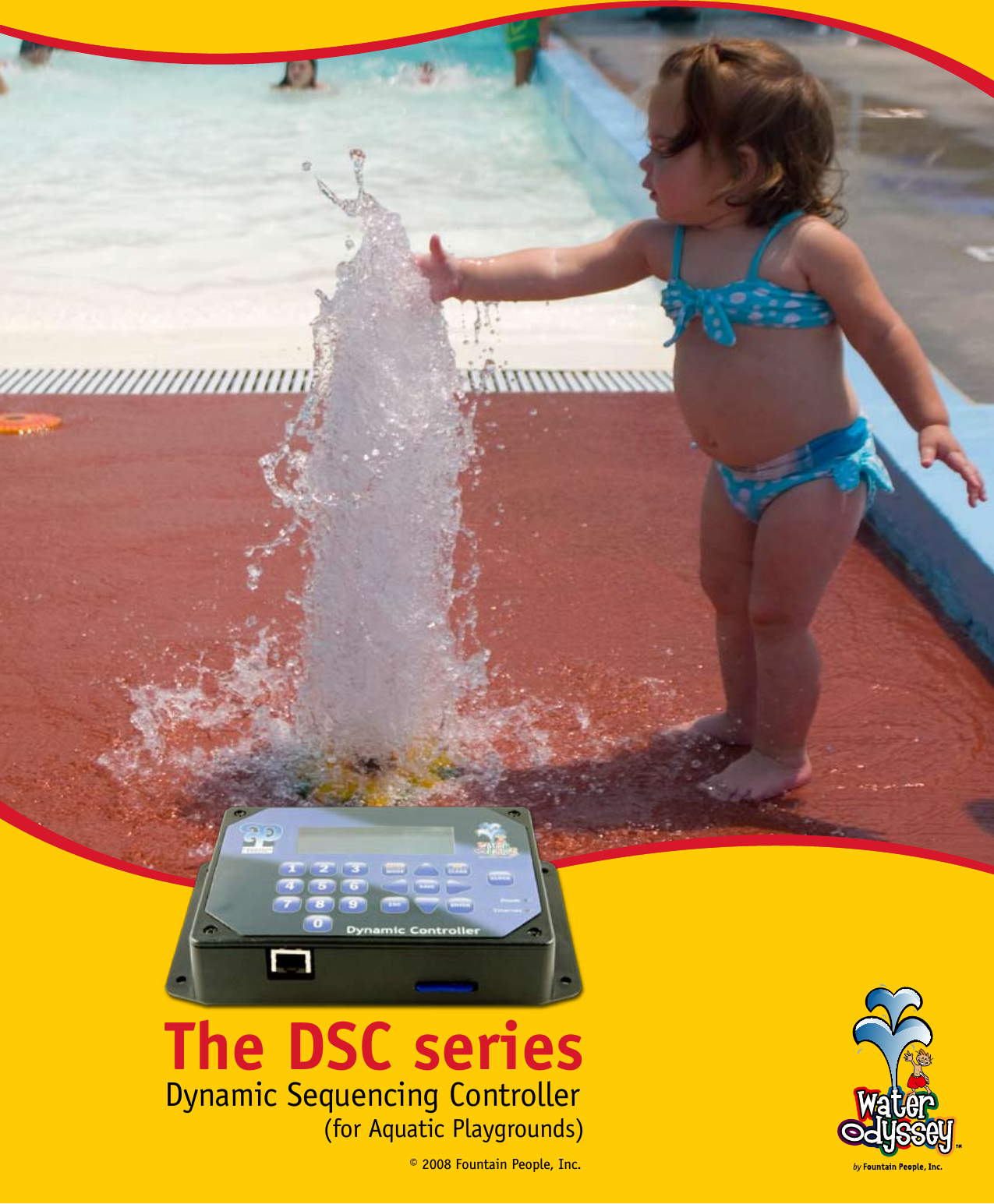
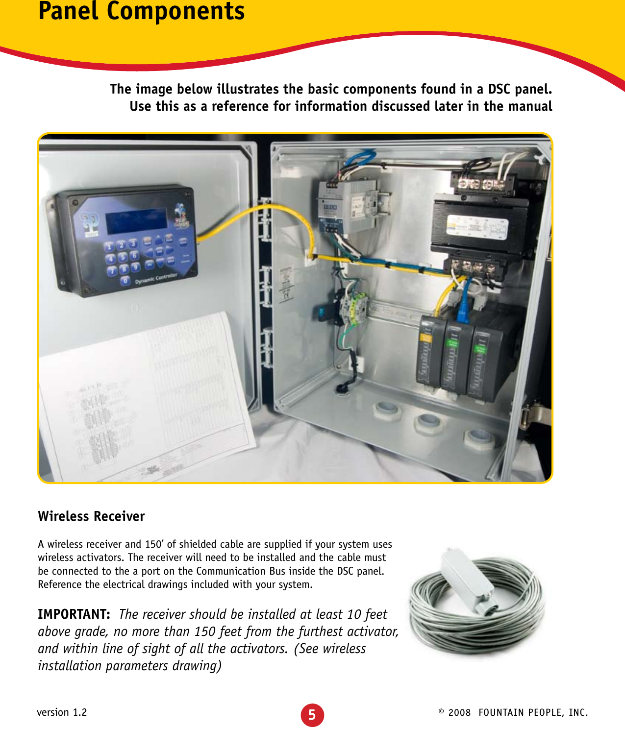
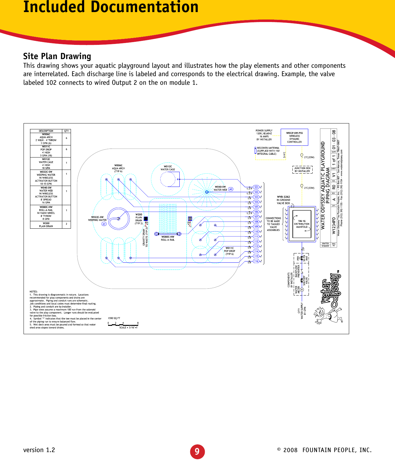
![© 2008 FOUNTAIN PEOPLE, INC.version 1.2Water Odyssey™ Dynamic Sequencing ControllerThis manual is intended to acquaint the user with both installation of the DSC and the procedures for modifying the various settings responsible for the behavior of the aquatic playground.The DSC ....................................................................... 2-6 Concept .................................................................................. 2 Advantages .............................................................................. 3 Features .................................................................................. 4 Component Identification ........................................................ 5-6Quick Start .................................................................7-19 Installation Documents ......................................................... 8-10 Basic Operation .................................................................. 11-16 System Tests ...................................................................... 17-19Aquatic Playground ................................................... 20-26 What is an Aquatic Playground? ............................................ 20-22 Modifying Events ................................................................ 23-261FCC ID: WIM0000010This device complies with part 15 of the FCC Rules. Operation is subject to the following two conditions: (1) This device may not cause harmful interference, and (2) this device must accept any interference received, including interference that may cause undesired operation.FCC ID: WIM0000020This device complies with part 15 of the FCC Rules. Operation is subject to the following two conditions: (1) This device may not cause harmful interference, and (2) this device must accept any interference received, including interference that may cause undesired operation.IC-7978A-0000010This Class [A] digital apparatus complies with Canadian ICES-003.Cet apparelj numériqué de la classe [A] est conformé à la norme NMB-003 du CanadaIC-7978A-0000020This Class [A] digital apparatus complies with Canadian ICES-003.Cet apparelj numériqué de la classe [A] est conformé à la norme NMB-003 du CanadaWarnings: Any changes or modifications to of the printed circuit board of this equipment could void the user’s authority to operate the equipment. Operation of an unapproved antenna circuit could void the user’s authority to operate the equipment.Water Odyssey™ devices by Fountain People Inc. may be used in the United States of America and Canada under one or more of the following identifiers:FCC ID: WIM0000010, IC:7978A-0000010FCC ID: WIM0000020, IC:7978A-0000020](https://usermanual.wiki/Fountain-People/0000010.user-manual-pt-1/User-Guide-1113908-Page-2.png)
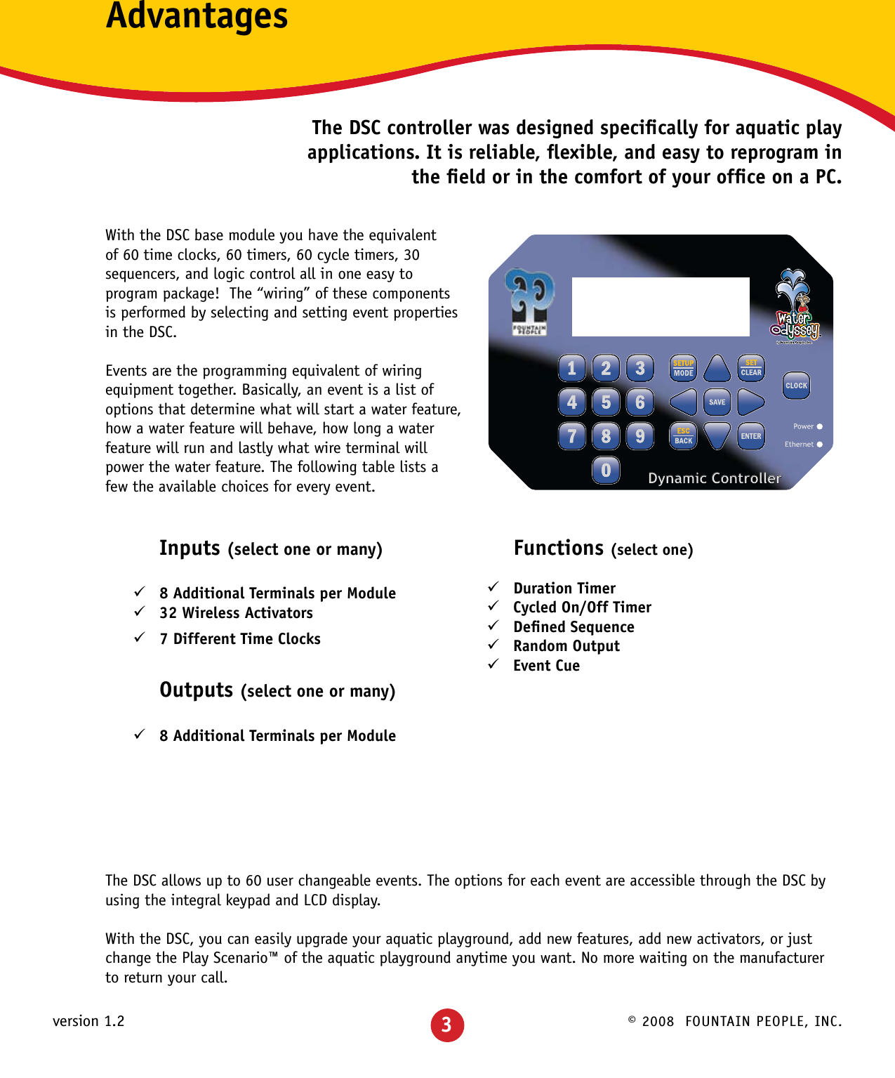
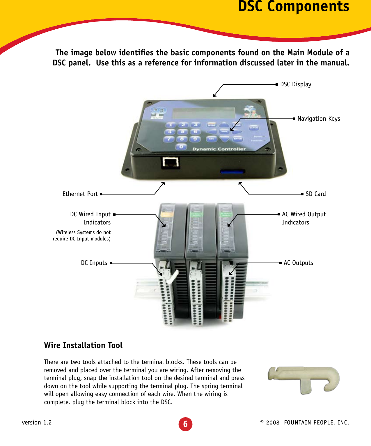
![© 2008 FOUNTAIN PEOPLE, INC.version 1.2Main Screen & KeypadMain ScreenThis screen is displayed after the DSC has powered up. This screen displays the Water Odyssey™ project number, the current state of the operating hours, system messages including when a wireless activator requires a new battery, and the current date and time.KeypadThe keypad consists of 20 keys used to navigate and modify all the settings in the DSC. This list describes their most common function.ClockPress this key at any time to cycle through operating modes.•Auto DSCwillrunaccordingtotheoperatinghours.•On DSCwillforceoperatinghourson.•Off DSCwillforceoperatinghoursoff.Setup | ModePress this key to access event settings, operating hours, system tests, and system setup. When a Password is set you are required to enter the password before gaining access to the controller settings.EnterUsed for navigation and selection of properties.ESC | BackUsed for navigation, pressing the [ESC | BACK] key will return you to the previous screen.SavePress this key at anytime to permanently store any changes that you have made. Set | ClearUsed to modify event properties, operating hours, and defined sequences.Left and Right ArrowsUsed to modify event properties and for navigating operating hours and defined sequences.Up and Down ArrowsUsed for navigation throughout the menus and settings.NumbersUsed to enter numeric values and for navigation shortcuts.W6874 Control System Push SetupOperating Hours: OnThr, Jan 01 11:23 AM11](https://usermanual.wiki/Fountain-People/0000010.user-manual-pt-1/User-Guide-1113908-Page-12.png)
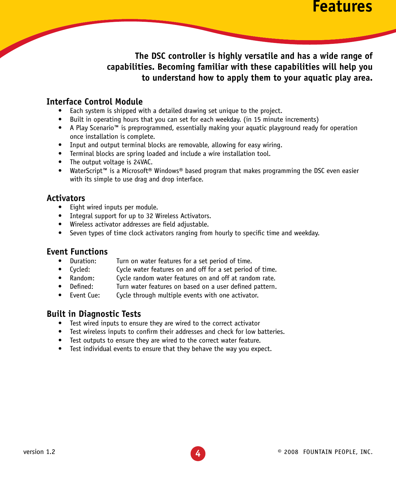
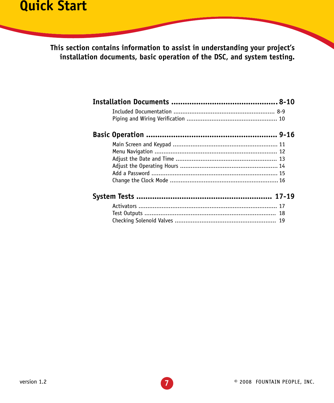
![© 2008 FOUNTAIN PEOPLE, INC.version 1.2 12Menu NavigationThe [UP ARROW] and [DOWN ARROW] keys are used to navigate through menu options. Note that not all menu items are displayed on the screen at once. This is illustrated by the two options System Status and System Setup shown below the screen to the left.To display these options on the screen scroll down using the [DOWN ARROW] key. The numbers to the left of the menu items are shortcut keys. These can be used instead of the arrows. For example pressing the [4] key will go directly to System Setup. Examples in this manual are shown using shortcut keys whenever possible.The screen above shows an arrow ( ³ ) pointing to the Events menu item. This arrow indicates the current item for selection. To select this item press the [ENTER] or [RIGHT ARROW] key. Doing so will display the Events screen. You can also press the shortcut key, [1].To access Operating Hours, scroll down using the [DOWN ARROW] key until the arrow points to the Operating Hours menu item and press the [ENTER] or [RIGHT ARROW] key. You can also press the shortcut key, [2].To access System Tests, scroll down using the [DOWN ARROW] key until the arrow points to the System Tests menu item and press the [ENTER] or [RIGHT ARROW] key. You can also press the shortcut key, [3].To access System Setup, scroll down using the [DOWN ARROW] key until the arrow points to the System Setup menu item and press the [ENTER] or [RIGHT ARROW] key. You can also press the shortcut key, [4].Controller Settings 1³Events 00 µ Operating Hours 2 System Status 3 System SetupController Settings 1³Events 00 µ Operating Hours 2 System Status 3 System SetupEvents 1³Add New µ EditMove:15min 10:45 AMSun | ¸¶¶¶¶¶·¶¶¶¶¶¶¹Mon | ¸·¶¶¶¶¶¶¹Tue | ¸·¶¶¶¶¶¶¹Controller Settings ´ Operating Hours 1³System Status µ System TestsSystem Status 1³Event 6 µ Module 3System Setup 1³Set Password µ Date: 01/01/2008Controller Settings ´ System Status 4³System SetupController Settings ´ Events 00 1³Operating Hours µ System TestsNote: At anytime press the [ESC | Back] key to return to the previous screen.](https://usermanual.wiki/Fountain-People/0000010.user-manual-pt-1/User-Guide-1113908-Page-13.png)
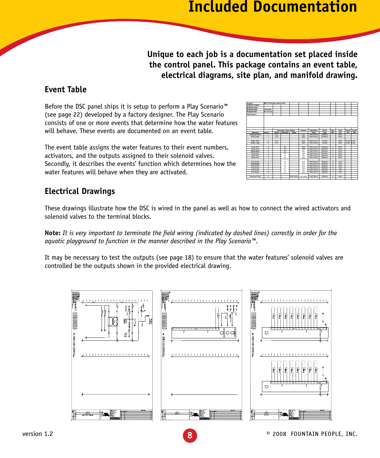
![© 2008 FOUNTAIN PEOPLE, INC.version 1.2System Setup ´ Date: 01/01/2008 3³Time: 11:23 AM µ Disable OutputsAdjust Date & TimeThe DSC has a built-in time clock with calendar that will maintain proper time and date even when the unit is not powered. This gives the DSC the capability of controlling events based on the time of day and the day of the week.Adjust the System TimeThe DSC is set to your aquatic playground’s time zone before leaving the factory. The time can be adjusted using the following procedure.Starting on the Main Screen, press [SETUP] [4] [3]. This will display the System Settings screen and place the cursor on the Time item. Next press the [RIGHT ARROW] to place the cursor in the Time field. Using the numeric keys enter the current time. To change between AM and PM position the cursor on the AM/PM using the [RIGHT ARROW] key and press the [SET|CLEAR] key.Example: How to change the time from 11:23 AM to 2:45 PM.Starting on the Main Screen, press the following keys:[SETUP] [4] [3] [RIGHT ARROW] [0] [2] [4] [5] [SET|CLEAR] [RIGHT ARROW]Adjust the System DateThe Date is preset before leaving the factory. The date can be adjusted using the following procedure.Starting on the Main Screen, press [SETUP] [4] [2]. This will display the System Settings screen and place the cursor on the Date item. If you are already on the System Setup screen use the [UP ARROW] and/or [DOWN ARROW] keys to scroll to the Date item. Next press the [RIGHT ARROW] to place the cursor in the Date field. Using the numeric keys enter the current date. Note that the DSC will support dates up to the year 2047.Example: How to change the date from 01/01/2008 to 08/11/2008Starting on the Main Screen, press the following keys:[SETUP] [4] [2] [RIGHT ARROW] [8] [1] [1] [0] [8]System Setup ´ Set Password 2³Date: 01/01/2008 µ Time: 11:23 AM13](https://usermanual.wiki/Fountain-People/0000010.user-manual-pt-1/User-Guide-1113908-Page-14.png)
![© 2008 FOUNTAIN PEOPLE, INC.version 1.2 14Adjust the Operating HoursYour aquatic playground operating hours can be uniquely set in 15 minute increments for each day of the week.The DSC is shipped with operating hours preset to open at 10:00 AM and close at 6:00 PM for your time zone. These hours can be modified to suit the requirements of the aquatic playground. Each day can have multiple open and close times and each day of the week can have its’ own unique operating hours.Access the Operating HoursStarting on the Main Screen, press [SETUP] [2]. This will display the Operating Hours screen and place the cursor on Monday at 10:00 AM.The top row displays the cursor move and the cursor location. The cursor move determines how many spaces the cursor will move when the [LEFT ARROW] and [RIGHT ARROW] keys are pressed. The move value can be adjusted by pressing the [SETUP|MODE] key. The possible values are 15 minutes and 2 hours.The cursor location is shown in the upper right corner, 10:45 AM on the screen above. This value will change when the [LEFT ARROW] or [RIGHT ARROW] key is pressed to reflect the current cursor location.Use the [UP ARROW] and [DOWN ARROW] keys to scroll through the days of the week. Use the [LEFT ARROW] and [RIGHT ARROW] keys to scroll through the times of the day. Press the [SET|CLEAR] key to set and clear the open and close times on the display.Example: Setting open and close timesUse the [LEFT ARROW] and [RIGHT ARROW] keys to scroll to the time you want the aquatic playground to open. Press the [SET|CLEAR] key, the screen should be similar to the following. The DSC automatically fills in the time to the right with dashed linesUsing the [LEFT ARROW] and [RIGHT ARROW] keys scroll to the time you want the aquatic playground to close. Press the [SET|CLEAR] key, the screen should be similar to the following:If you insert a time in-between the open and close times all the open and close times to the right will be inverted. The screen should be similar to the following:Move:15min 10:45 AMSun | ¸¶¶¶¶¶·¶¶¶¶¶¶¶Mon | ¸·¶¶¶¶¶¶¶Tue | ¸·¶¶¶¶¶¶¶Wed | ¸·¶¶¶¶¶¶¶Thr | ¸·¶¶¶¶¶¶¶Fri | ¸·¶¶¶¶¶¶¶Sat | ¸·¶¶¶¶¶¶¶ ¸¶¶¶·¶¶¶·¶¶¶·¶¶¶·¶¶¶·¶¶¶·¶¶¶·¶¶¶·¶¶¶·¶ ¸¶¶¶·¶¶¶·¶¶¶·¶¶¶·¶¶¶·¶¶¶·¶¶¶¹ ¸¶¶¶·¶¶¶·¶¶¶·¶¶¶·¶¹ ¸¶¶¶·¶¶¶·¶](https://usermanual.wiki/Fountain-People/0000010.user-manual-pt-1/User-Guide-1113908-Page-15.png)
![© 2008 FOUNTAIN PEOPLE, INC.version 1.2Add a PasswordTo prevent unauthorized personnel from modifying settings, the DSC can be password protected. Once enabled, a password is required every time the [SETUP] key is pressed to allow access to the controller’s settings.The DSC is shipped with password protection enabled. The default password is 1155. To modify password protection and set a new system password perform the following steps.Starting at the Main screen, press [SETUP] enter the password [1] [1] [5] [5] navigate to the password settings [4] [1]. This will display the Password screen and wait for you to enter a four digit password.Next press the four desired keys to set the password. A password can only consist of numeric values. After the four keys have been pressed a second password screen will be displayed requiring that the four keys are reentered for confirmation. After the password is reentered you are returned to the System Setup screen and password protection is now enabled. Once set, you will be asked to enter the password to gain access to the DSC’s settings.Example: How to enable password protection and set the password to 3194.Starting on the Main Screen, press the following keys:[SETUP] [1] [1] [5] [5] [4] [1] [3] [1] [9] [4] [3] [1] [9] [4]To disable password protection go to the set password screen and enter 0000 for the password. This instructs the DSC to disable password protection.Example: How to disable password protection.Starting on the Main Screen, press the following keys:[SETUP] [Enter Password] [4] [1] [0] [0] [0] [0] [0] [0] [0] [0] Enter Password .... Confirm Password ....15](https://usermanual.wiki/Fountain-People/0000010.user-manual-pt-1/User-Guide-1113908-Page-16.png)
![© 2008 FOUNTAIN PEOPLE, INC.version 1.2 16Change the Clock ModeThe operating hours can be overridden simply by pressing the clock override button. This will allow you to operate the aquatic playground while operating hours are off, and shut it down while the operating hours are on.Force Operating Hours OnPress the [CLOCK] key until you see the Operating Hours Forced On screen. While the DSC display is on the main screen the Forced On screen will periodically flash as a reminder that the operating hours are not in their normal automatic mode.All Events set to run while operating hours are on will be enabled. Events requiring an activator in order to operate will need to be activated as they would normally.Force Operating Hours OffPress the [CLOCK] key until you see the Operating Hours Forced Off screen. While the DSC display is on the main screen the Forced Off screen will periodically flash as a reminder that the operating hours are not in their normal automatic mode. All events that require operating hours on in order to operate will be disabled.Set Operating Hours to AutomaticPress the [CLOCK] key until you see the Operating Hours Auto screen. The aquatic playground will start and stop according to the Operating Hours settings. Operating Hours Forced On Operating Hours Forced Off Operating Hours Auto](https://usermanual.wiki/Fountain-People/0000010.user-manual-pt-1/User-Guide-1113908-Page-17.png)