Foxconn 7870 User Manual To The 22518227 20dc 4d9d 9589 38d894b359b7
User Manual: Foxconn 7870 to the manual
Open the PDF directly: View PDF ![]() .
.
Page Count: 228 [warning: Documents this large are best viewed by clicking the View PDF Link!]
- NCR 7870 Scanner/Scale User's Guide
- Chapter 1: Introduction
- Chapter 2: Features, Functions, and Kits
- Chapter 3: Site Preparation
- Getting Started
- About Site Preparation
- Customer Responsibilities
- Environmental Requirements
- Checkstand Power and Wiring Considerations
- Checkstand Considerations
- Cable Lengths and Hole Sizes
- Cable Hole Diameters
- DC Power Cable – Power Supply to 7870
- AC Power Cords – Outlet to Power Supply
- Remote Display Cables
- Interface Cables - NCR Host Terminals
- Interface Cables – NCR Host Terminals (cont.)
- Interface Cables - Casio Host Terminals
- Interface Cables – Data Checker Host Terminals
- Interface Cables – Epson Host Terminals
- Interface Cables – Gilbarco Host Terminals
- Interface Cables – IBM Host Terminals
- Interface Cables – ICL Host Terminals
- Interface Cables – ICL Host Terminals (cont.)
- Interface Cables – Microbilt Host Terminals
- Interface Cables – NEC Host Terminals
- Interface Cables – SASI Host Terminals
- NCR 7870 Dimensions
- Chapter 4: Installation
- Chapter 5: Calibration
- Chapter 6: Operation
- Chapter 7: Programming
- General
- How to Program the NCR 7870
- Program Parameter Descriptions
- PACESETTER
- Special Programming
- ASCII Code Chart
- Chapter 8: Troubleshooting
- Appendix A: Programming Worksheets
- General
- Programming Parameter Defaults
- Worksheets
- 10 Communications Protocol
- 11 Good Read Tone
- 12 Timers
- 13 Bar Codes - 1
- 14 Bar Codes - 2
- 15 Bar Codes - 3
- 17 Bar Codes - 4
- 16 Label Identifiers
- 20 RS-232 Parameters - 1
- 21 RS-232 Parameters - 2
- 22 RS-232 Prefix Byte
- 23 RS-232 Terminator Byte
- 24 RS-232 Communications Options
- 30 Scale Parameters
- 32 Miscellaneous Parameters
- ASCII Code Chart
- Index
- Feedback

NCR 7870 Scanner/Scale
Release 1.0
User's Guide
BST0-2121-90
Issue G

The product described in this book is a licensed product of NCR Corporation.
Trademark Information
It is the policy of NCR Corporation (NCR) to improve products as new technology, components, software,
and firmware become available. NCR, therefore, reserves the right to change specifications without prior
notice.
All features, functions, and operations described herein may not be marketed by NCR in all parts of the
world. In some instances, photographs are of equipment prototypes. Therefore, before using this document,
consult with your NCR representative or NCR office for information that is applicable and current.
To maintain the quality of our publications, we need your comments on the accuracy, clarity, organization,
and value of this book.
Address correspondence to:
Retail Solutions Group−Atlanta
NCR Corporation
2651 Satellite Blvd.
Duluth, GA 30096
Copyright © 1999
By NCR Corporation
Dayton, Ohio U.S.A.
All Rights Reserved

User's Guide i
Table of Contents
Chapter 1: Introduction
About the NCR 7870 Scanner/Scale............................1-2
Models.....................................................................1-2
Reading the Product Number ...............................1-3
Common Features..................................................1-3
7870-1000-9090........................................................1-4
7870-2000-9090........................................................1-4
7870-3000-9090........................................................1-4
7870-4000-9090........................................................1-4
7870-4500-9090........................................................1-4
Chapter 2: Features, Functions, and Kits
General Features and Functions..................................2-1
Bar Code Recognition.............................................2-1
Bi-Optic Scanning...................................................2-2
Decode Features .....................................................2-2
PACESETTER Plus.............................................2-2
Displays...................................................................2-3
NCR 7825 Remote Display................................2-3
Integrated Display..............................................2-4
No Display..........................................................2-5
Interface Types .......................................................2-5
Laser Scanner..........................................................2-5
Power Supply .........................................................2-5
Programming the 7870...........................................2-6
Scale Certifications .................................................2-7
Scan Zone................................................................2-8

ii User's Guide
Scanner Power Requirements................................2-8
Soft Power Down....................................................2-8
Top Plates and Scan Windows..............................2-9
Top Plates............................................................2-9
Slot Scanner Window.........................................2-9
Side Scanner Window......................................2-10
Scale Features and Functions.....................................2-11
Scale Functions and Features...............................2-11
Kits...............................................................................2-12
Chapter 3: Site Preparation
Getting Started..............................................................3-2
About Site Preparation.................................................3-4
Customer Responsibilities............................................3-6
Environmental Requirements......................................3-7
Operating Range ................................................3-7
Extreme Operating Range.................................3-7
Storage Range.....................................................3-8
Transit Range......................................................3-8
Checkstand Power and Wiring Considerations.........3-9
Power Considerations............................................3-9
Power Applications............................................3-9
Power Transients Protection..............................3-9
Wiring Considerations.........................................3-10
U.S., Canadian, and Japanese Checkstand
Wiring ...............................................................3-10
European Checkstand Wiring.........................3-11
International Checkstand Wiring....................3-12
Wiring Instructions ..............................................3-13
Running Feeder Lines from Main Service
Panel..................................................................3-13
Circuit A............................................................3-13

User's Guide iii
Circuit B............................................................3-14
Circuit C............................................................3-14
Checkstand Considerations.......................................3-15
Ventilation Requirements....................................3-15
Service Clearance..................................................3-16
Display Clearance.................................................3-17
Item Diverter.........................................................3-17
Checkstand Hole ..................................................3-18
Checkstand Hole - Models 1000 & 2000 .........3-19
Checkstand Hole - Models 3000, 4000, & 45003-20
Cable Lengths and Hole Sizes ...................................3-21
Cable Hole Diameters..........................................3-21
DC Power Cable – Power Supply to 7870...........3-21
AC Power Cords – Outlet to Power Supply.......3-22
Remote Display Cables........................................3-22
Interface Cables - NCR Host Terminals..............3-23
Interface Cables – NCR Host Terminals (cont.) .3-24
Interface Cables – NCR Host Terminals (cont.) .3-25
Interface Cables - Casio Host Terminals.............3-25
Interface Cables – Data Checker Host Terminals3-26
Interface Cables – Epson Host Terminals...........3-26
Interface Cables – Gilbarco Host Terminals.......3-26
Interface Cables – IBM Host Terminals..............3-27
Interface Cables – ICL Host Terminals...............3-27
Interface Cables – ICL Host Terminals (cont.)....3-28
Interface Cables – Microbilt Host Terminals......3-28
Interface Cables – NEC Host Terminals.............3-28
Interface Cables – SASI Host Terminals.............3-29
NCR 7870 Dimensions................................................3-30
NCR 7870-1000 & 2000 Models ...........................3-30
NCR 7870-3000 Model..........................................3-31

iv User's Guide
NCR 7870-4000 & 4500 Models ...........................3-32
Chapter 4: Installation
Getting Started..............................................................4-1
Reporting a Damaged Unit....................................4-1
What’s in the Box....................................................4-1
Cable Verification...................................................4-2
Checkstand Verification.........................................4-2
Installing Unit in Checkstand......................................4-3
Instructions.............................................................4-3
Install Cables.......................................................4-3
Determining if the Unit is Operational.......................4-8
NCR 7870-1000 and 3000 Scanners........................4-8
NCR 7875-2000, 4000, and 4500 Scanner/Scales..4-8
If the NCR 7870 Does Not Pass Level O
Diagnostics..............................................................4-8
Checkout Reading Operation................................4-9
Programming..........................................................4-9
Determining Communications Protocol...................4-10
Scale Address for IBM................................................4-11
Chapter 5: Calibration
General ..........................................................................5-1
Calibration Procedure..................................................5-3
Section 1: Exercising the Scale..............................5-3
Section 2: Accessing the Calibration Switch........5-4
Section 3: Connecting the Field Service
Calibration Display................................................5-7
Section 4: Performing the Calibration..................5-9
Verifying Calibration..................................................5-11
Procedure 1: Increasing Load Test.....................5-12
Procedure 2: Over-Capacity Test........................5-13

User's Guide v
Procedure 3: Decreasing Load Test....................5-14
Instructions.......................................................5-14
Procedure 4: Shift Test........................................5-15
Securing the Calibration Switch................................5-16
Chapter 6: Operation
About Using the Operator Controls............................6-2
Scan Windows........................................................6-2
Status Indicators.....................................................6-2
Motion Detector......................................................6-3
Reset / Scale Zero Button......................................6-3
Audible Tone..........................................................6-3
Voice Messages.......................................................6-3
About Using the Scanner.............................................6-4
Proper Label Orientation.......................................6-4
Active Scan Zone....................................................6-5
Multiple Reads........................................................6-5
Bar Code Quality....................................................6-6
Operating Instructions .................................................6-7
Power Up................................................................6-7
Scanner Only Models.........................................6-7
Scanner/Scale Models .......................................6-7
Scanning Procedure................................................6-8
Instructions.........................................................6-8
Not-On-File Error...................................................6-8
Weighting Procedure.............................................6-9
Instructions.........................................................6-9
Changing the Good Read Tone...........................6-10
Instructions.......................................................6-10
Routine Maintenance..................................................6-11
Instructions.......................................................6-11

vi User's Guide
Chapter 7: Programming
General ..........................................................................7-1
How to Program the NCR 7870...................................7-3
Creating the Program.............................................7-3
Step 1. Writing the Program.............................7-3
Step 2. Entering the Program............................7-3
Step 3. Save the Program..................................7-4
Programming Mode...............................................7-5
Programming Tags.................................................7-6
Abort ...................................................................7-6
Default.................................................................7-7
End ......................................................................7-7
Hex 0 – Hex F......................................................7-7
Programming Mode...........................................7-8
Save and Reset....................................................7-8
Program Entry Example.........................................7-9
Programming Tips ...............................................7-12
Program Parameter Descriptions..............................7-13
Communications Protocol...................................7-13
Defaults.............................................................7-13
Specific Program Parameters...........................7-13
Programming Example....................................7-17
Good Read Tone...................................................7-18
Defaults.............................................................7-18
Specific Program Parameters...........................7-18
Program Example.............................................7-19
Timers....................................................................7-20
Defaults.............................................................7-20
Specific Program Parameters...........................7-20
Program Example.............................................7-21
Bar Codes – 1........................................................7-22

User's Guide vii
Defaults.............................................................7-22
Specific Program Parameters...........................7-22
Program Example.............................................7-24
Bar Codes – 2........................................................7-25
Defaults.............................................................7-25
Specific Program Parameters...........................7-25
Program Example.............................................7-27
Bar Codes – 3........................................................7-28
Defaults.............................................................7-28
Specific Program Parameters...........................7-28
Program Example.............................................7-30
Bar Codes – 4........................................................7-31
Defaults.............................................................7-31
Specific Program Parameters...........................7-31
Program Example.............................................7-32
Label Identifiers....................................................7-33
Defaults.............................................................7-33
Specific Program Parameters...........................7-34
Program Example.............................................7-37
RS-232 Parameters – 1..........................................7-39
Defaults.............................................................7-39
Specific Program Parameters...........................7-39
Program Example.............................................7-41
RS-232 Parameters – 2..........................................7-42
Defaults.............................................................7-42
Specific Program Parameters...........................7-42
Program Example.............................................7-44
RS-232 Prefix Byte ................................................7-45
Defaults.............................................................7-45
Specific Program Parameters...........................7-45
Program Example.............................................7-46

viii User's Guide
RS-232 Terminator Byte.......................................7-47
Defaults.............................................................7-47
Specific Program Parameters...........................7-47
Program Example.............................................7-48
RS-232 Communications Options .......................7-49
Defaults.............................................................7-49
Specific Program Parameters...........................7-49
Program Example.............................................7-52
Scale Parameters...................................................7-53
Defaults.............................................................7-53
Specific Program Parameters...........................7-53
Program Example.............................................7-54
Miscellaneous Parameters...................................7-55
Defaults.............................................................7-55
Specific Program Parameters...........................7-55
Program Example.............................................7-57
PACESETTER Plus Information................................7-59
Mode 1 - Inquiry...................................................7-59
Mode 2 - Real Time...............................................7-60
Mode 3 – Normal..................................................7-62
Host Access to Tallies...........................................7-64
Examples of Host Access to Tallies.................7-64
Host Reset of Tallies.........................................7-67
Special Programming.................................................7-68
Delay Weight Data to IBM Host Terminal.........7-68
EAN/JAN/UPC Multi-Symbol Scanning
Parameters ............................................................7-69
Label Construction...........................................7-69
Single Label Restriction....................................7-69
Transmitting Label Data..................................7-69
Early Beep Disable................................................7-72
Good Read Tone Presets......................................7-73

User's Guide ix
Good Weigh Tone When Transmitting Data......7-74
Terminal Coupon Interface Parameters..............7-75
ASCII Code Chart.......................................................7-77
Chapter 8: Troubleshooting
Fault Identification .......................................................8-1
Scanner Troubleshooting Chart...................................8-2
Scale Troubleshooting Chart........................................8-3
Voice Messages Troubleshooting Chart......................8-5
Appendix A: Programming Worksheets
General .........................................................................A-1
Purpose...................................................................A-1
Format....................................................................A-1
Shortcuts.................................................................A-1
Defaults..................................................................A-2
Hex Characters ......................................................A-2
Program Entry .......................................................A-2
Programming Parameter Defaults .............................A-3
Worksheets...................................................................A-6

x User's Guide
Revision Record
Issue Date Remarks
A Oct 92 First Issue
B Dec 92 Miscellaneous Changes
C Feb 93 Miscellaneous Changes
D Jan 94 Miscellaneous Changes
E Oct 94 Miscellaneous Changes
FFeb 99 Complete Revision
G Nov 99 Miscellaneous Changes

User's Guide xi
Radio Frequency Interference Statements
Federal Communications Commission (FCC)
Information to User
This equipment has been tested and found to comply with the limits for a Class A
digital device, pursuant to Part 15 of FCC Rules. These limits are designed to provide
reasonable protection against harmful interference when the equipment is operated in
a commercial environment. This equipment generates, uses, and can radiate radio
frequency energy and, if not installed and used in accordance with the instruction
manual, may cause harmful interference to radio communications. Operation of this
equipment in a residential area is likely to cause interference in which case the user
will be required to correct the interference at his own expense.
NCR is not responsible for any radio or television interference caused by unauthorized
modification of this equipment or the substitution or attachment of connecting cables
and equipment other than those specified by NCR. The correction of interference
caused by such unauthorized modification, substitution or attachment will be the
responsibility of the user. The user is cautioned that changes or modifications not
expressly approved by NCR may void the user’s authority to operate the equipment.
Canadian Department of Communications
This digital apparatus does not exceed the Class A limits for radio noise emissions
from digital apparatus set out in the Radio Interference Regulations of the Canadian
Department of Communications.
Le présent appareil numérique n’émet pas de bruits radioélectriques dépassant les
limites applicables aux appareils numériques de la classe A prescrites dans le
Règlement sur le brouillage radioélectriques édicté par le ministrère des
Communications du Canada.
Voluntary Control Council For Interference (VCCI)

xii User's Guide
C E Mark Applicability
This product conforms to European Union (EU) Directives:
Council Directive 90/384/EEC
Non-Automatic Weighing Instruments
Scale Regulatory
Notification of country, state, and local regulatory agencies of
weighing device installation is required. Failure to comply with can
result in criminal prosecution and jeopardize the ability to conduct
normal business. The NCR 7870 Scanner/Scale has been certified in
many countries. Contact the NCR Office of Weights & Measures and
Laser Safety for specific country approvals.
NCR Office of Weights & Measures and Laser Safety
Dennis A. Krueger
2651 Satellite Boulevard
Duluth, GA 30096-5810
Phone: 770-623-7743
Fax: 770-623-7827
E-Mail: Dennis.Krueger@AtlantaGA.NCR.COM
Web Site: http://gedwards.AtlantaGA.NCR.Com/kruegd

User's Guide xiii
Declaration of Conformity
Manufacturer’s Name NCR Corporation
Manufacturer’s Address NCR Corporation
Retail Solutions Group – Atlanta
2651 Satellite Boulevard
Duluth, GA 30096-5810
Type of Equipment Information Technology Equipment – Bar Code
Scanner
Model Number Class NCR 7870-1000, NCR 7870-2000, NCR 7870-3000,
NCR 7870-4000, NCR 7870-4500
NCR Corporation, 1700 South Patterson Boulevard, Dayton, OH 45459,
USA, declares that the equipment specified conforms to the referenced
EU Directives and Harmonized Standards.
EU Directive Harmonized Standard(s)
89/336/EEC (EMC) EN 55022: 1987 (CISPR 22)
EN 50082-1, Part 1: 1992
IEC 801-2: 1984
IEC 801-3: 1984
IEC 801-4: 1988
*90/384/EEC
(Weights & Measures) EN45501
This Directive is not applicable to NCR 7870-1000 or NCR 7870-3000
Director of Quality Assurance
NCR Corporation
Retail Solutions Group — Atlanta
2651 Satellite Boulevard
Duluth, GA 30096-5810
European Contact:
International IP Counsel
915 High Road, North Findlex
London N12 8QJ
United Kingdom
xiv User's Guide
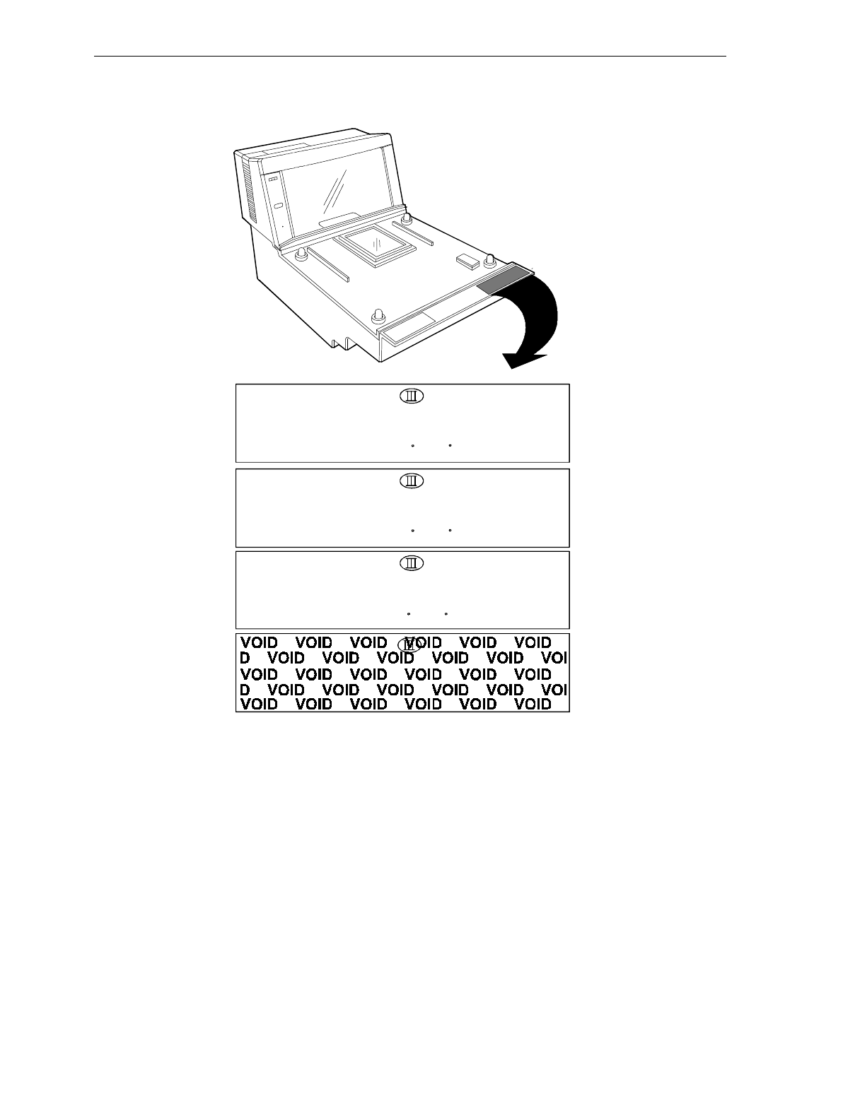
Scale Identification Label
NCR CORPORATION
Model 7875-2000
Max 13.995 kg Min 0.1 Kg ID
e = d = 0.005 kg Approval
Lim 19.990 kg +10 C /+40 C Serial No
NCR CORPORATION
Model 7875-2000
Max 30.00 Ib Min 0.2 lb ID
e = d = 0.01 lb Nmax3000 Approval
Lim 44.00 lb +10 C /+40 C Serial No
NCR CORPORATION
Model 7875-2000
Max 30.00 Ib Min 0.2 lb ID
e = d = 0.01 lb Nmax3000 Approval
Lim 44.00 lb +10 C /+40 C Serial No
13.995 Kilogram (kg) Label
Pound (lb) Label
Removing Label causes
VOID Indication
NCR CORPORATION
Model 7875-2000
Max 9.995 kg Min 0.1 Kg ID
e = d = 0.005 kg Approval
Lim 19.990 kg +10 C /+40 C Serial No
9.995 Kilogram (kg) Label
16884
Note: e = scale interval; d = scale division;
Max 30.00 lb = maximum weight permitted on scale
Min 0.2 lb = minimum weight that should be measured on scale
Nmax3000 = maximum scale divisions
User's Guide xv
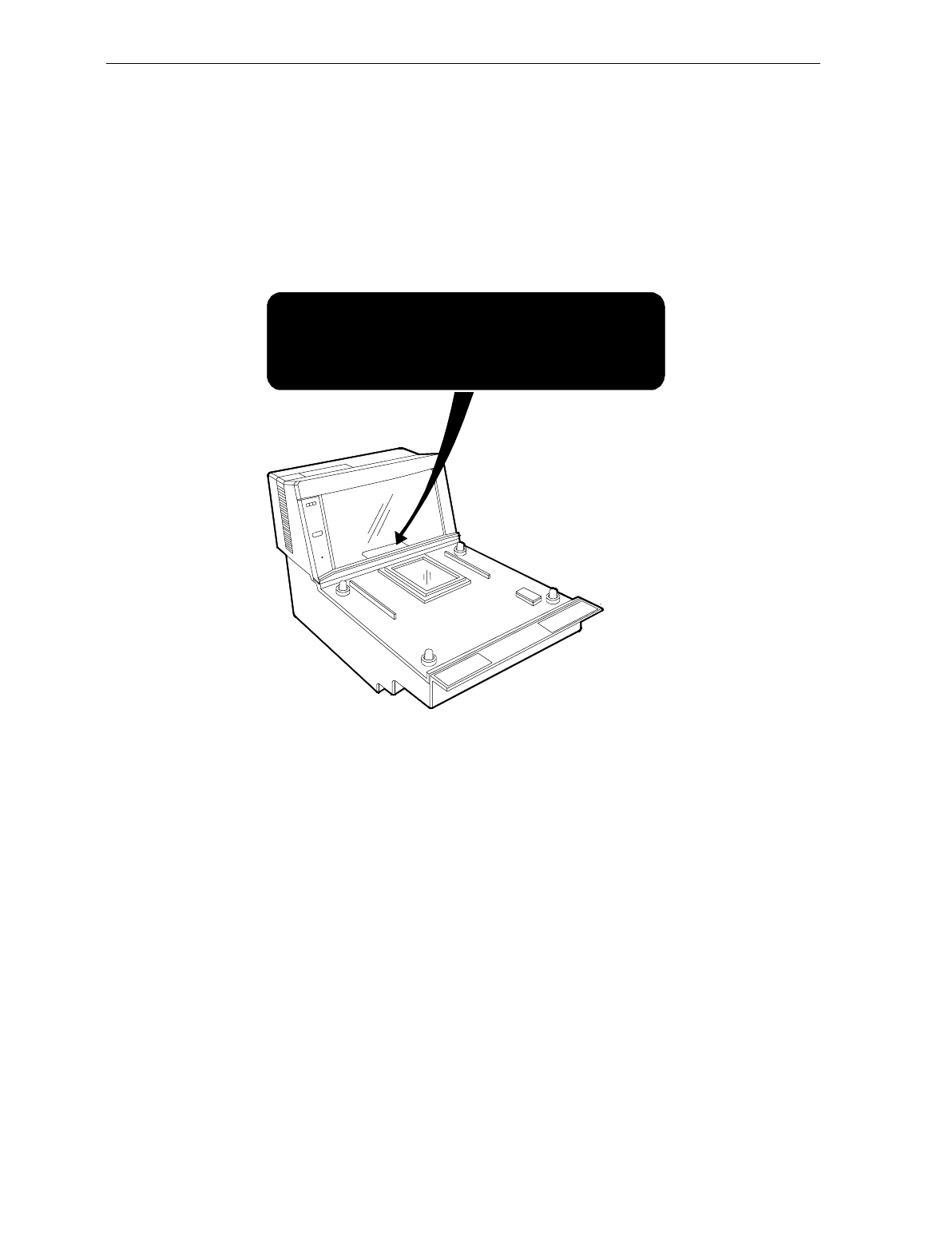
Laser Safety
The NCR 7870 Scanner is not intended for long-term viewing of the
direct laser light. However, the unit is safe if used as it was intended.
Laser Safety Label
R0130
(IEC CLASS 1 LASER PRODUCT)
Class IIa Laser Product. Avoid Long-Term Viewing of Direct Laser Light.
Appareil á laser de classe IIa Dviter toute exposition
prolongée de la vue á la lumiére laser directe.
Clase IIa Producto Laser. Traté de no ver directamente él Rayo
Laser por mucho tiempó.
xvi User's Guide
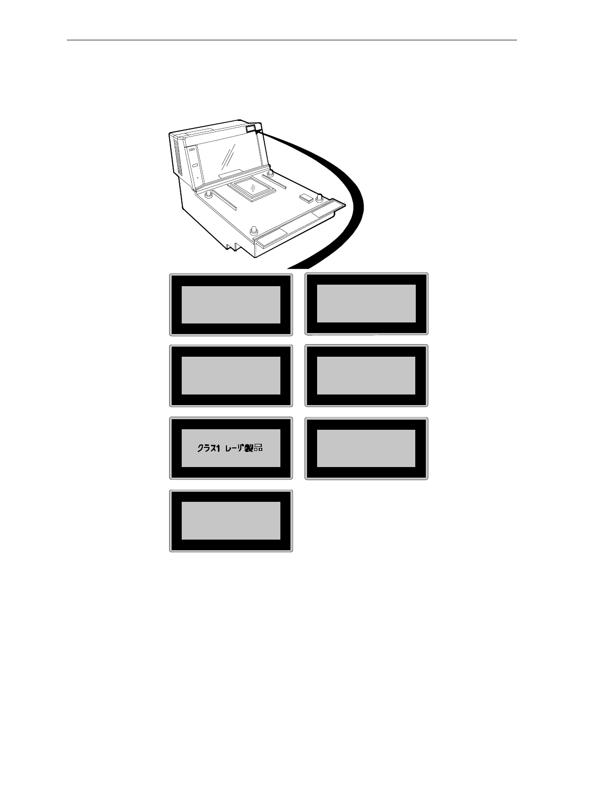
Country Language Specific IEC Class 1 Laser Labels
CLASS 1 LASER
PRODUCT (IEC 825)
APPAREIL A LASER
DE CLASS 1
LASER KLASS 1
Zeitbasis 1000 s
PRODUCTO LASER
CLASE 1
LUOKAN 1
LASERELAITE
KLASS 1
LASER APPARAT
R0130B
User's Guide xvii
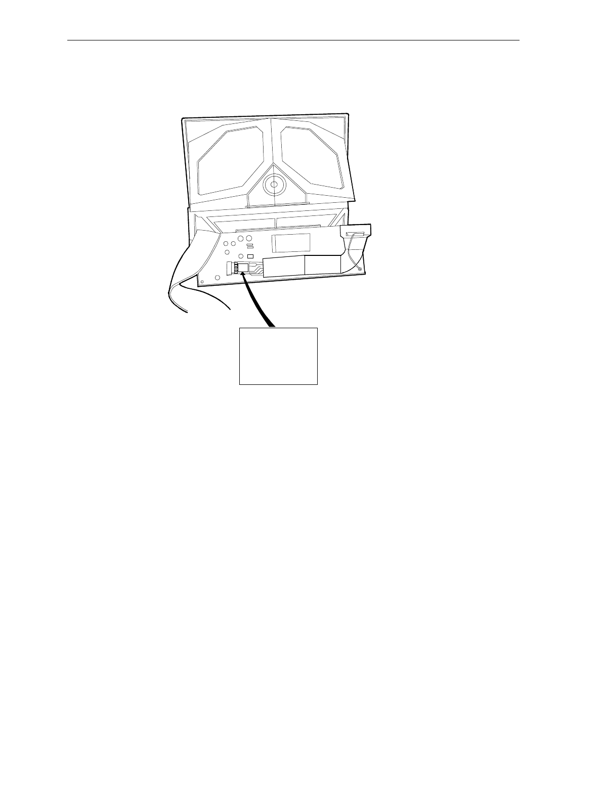
Laser Module Label
R0132A
This laser module
does not comply
with 21CFR1040.
USE ONLY AS A
COMPONENT.
Laser Power The NCR 7870 Scanner meets the following laser power requirements.
• Class IIa CDRH (Center for Devices and Radiological Health)
• Class 1 EN60-825 (Europäische Norm)
• Class 1 IEC 825-1 1993 (International Electrotechnical
Commission)

xviii User's Guide
Following is the radiant energy of the laser light as applied to each of
the specified requirements.
Maximum Average Radiant Power (CDRH Calculation) 0.87 microwatts
Accessible Emission Limit (CDRH Calculation) 3.9 microwatts
Maximum Radiant Power (EN60825-1 / IEC 825-1 Calculation) 0.45 milliwatts
Accessible Emission Limit (EN60825-1 / IEC 825-1 Calculation) 0.59 milliwatts
Caution: Use of controls or adjustments or performance of procedures
other than specified herein may result in hazardous radiation
exposure.
Chapter 1: Introduction
This chapter describes the models, features, and kits available for the
7870 line of scanner/scales. To familiarize you with the 7870, there is a
general overview on the unit, the models, and major components.
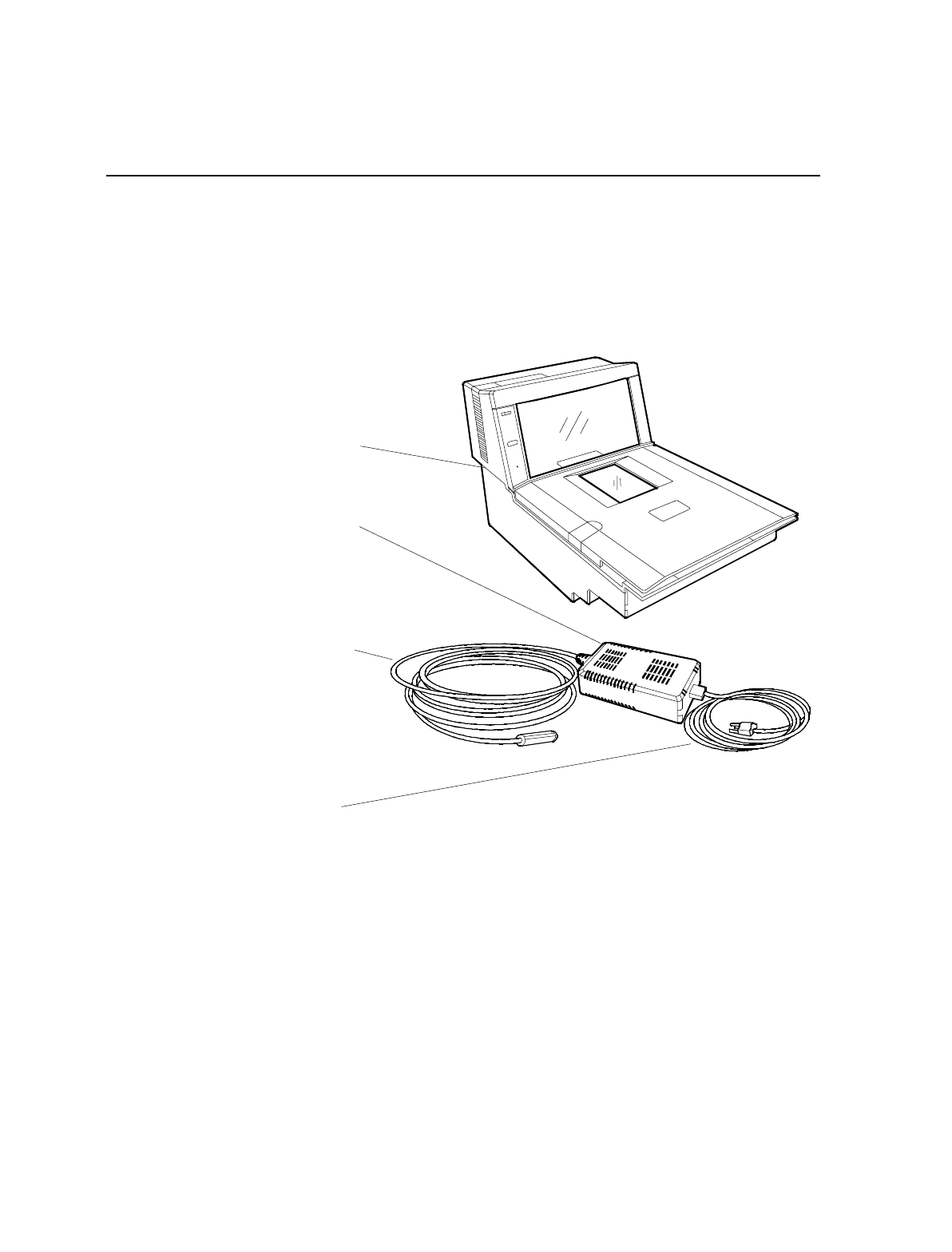
Power Supply
R0122
NCR 7870
Scanner/Scale
Power Cable
Power Cord

1-2 Chapter 1: Introduction
About the NCR 7870 Scanner/Scale
The NCR 7870 is used in high-performance scanning applications in
food distribution, mass merchandise, warehouse clubs, and large drug
store chains. It is a bi-optic scanner/scale that combines the
characteristics of a slot (horizontal) scanner and a side (vertical)
scanner into a single cabinet.
Bi-optical scanning creates a larger, four-sided scan zone which allows
the 7870 to read bar codes faster and with less orientation effort from
the checker. Scan line speeds of 2,400 lines per second permit
continuous item speeds of 2 meters per second. A good checker
operates in the range of 0.8 to 1.0 meters per second.
The PACESETTER Plus technology, available as an upgrade over the
Standard Decode feature, analyses and corrects information from
defective labels. PACESETTER Plus also keeps track of bad labels so
you can identify products and manufacturers with poor label quality.
The scale will weight items less five pounds (2.27 kg) in 0.9 seconds.
The weight plate is offset toward the checker, allowing the checker to
do what is natural when lifting heavy objects – pull the weight closer to
the body. This lessens operator lower back strain.
The overall result of these and many other design qualities is an
ergonomic scanner/scale with a very high first-pass read rate.
Models The NCR 7870 is available in five models:
• 7870 - 1000 - 9090 – scanner only, standard length
• 7870 - 2000 – 9090 - scanner and scale, standard length
• 7870 - 3000 – 9090 - compact scanner only
• 7870 - 4000 – 9090 - compact scanner/scale (third party scale,
European market)
• 7870 - 4500 – 9090 - compact scanner/scale (NCR scale)

Chapter 1: Introduction 1-3
Reading the Product Number
Class 7870
Major Model:
10 = Scanner (Standard Size)
20 = Scanner/Scale (Standard Size)
30 = Scanner (Compact)
40 = Scanner/Scale (Mid-Size, European Scale)
45 = Scanner/Scale (Mid-Size)
Sub-Model: none
Power: 90 = No Characteristics
Language: 90 = No Characteristics
14943
7870 XX00 90 90
Common Features
• Standard Decode or PACESETTER Plus and Standard Decode
• Interfaces for popular host terminals
• Large selection of power cords to meet custom and regional
needs while providing flexible configurations with the
universal power supply
• Data cables ordered separate or as part of a kit
• For Scanner/Scale models -- NCR 7825 Remote Display
(standard for current models), Integrated Display, or No Display
• Print or on-line documentation
• Choice of Stainless Steel Top Plate equipped with either
Sapphire or Diamond-Coated Glass Scan Window
• Custom labels for the scanner and scale to meet local
requirements for laser safety and/or weights and measures

1-4 Chapter 1: Introduction
7870-1000-9090This is the standard bi-optic scanner only model. It is full-sized,
designed to fit in a 20+ inch (51+ cm) wide checkstand. It can be
configured with a variety of top plates and glass options. The 7870-
1000 will fit into the counter hole for the NCR 7820.
7870-2000-9090This is the standard bi-optic scanner/scale model. It is identical to the
7870-1000 with the addition of a scale unit. The 7870-2000 can be
ordered with the post-mounted NCR 7825 Remote Display (standard),
an integrated display, or no display. The 7870-2000 will fit into the
counter hole for the NCR 7820.
7870-3000-9090This is the compact, bi-optic, scanner only model. With the scale bed
removed, the length is reduced to 34.3 cm (13.5 in.) to fit in European
checkstands where space is tight and the checker is often seated.
7870-4000-9090This is the subcompact scanner/scale model. With a length of 43 cm
(17 in.), the 7870-4000 has a footprint between that of the full-sized
1000/2000 models and the compact 3000 model.
The 4000 model uses a price-computing scale to meet European
requirements. This scale uses information obtained from the host
terminal and the measured weight to calculate the price internally. The
price computing function makes the 4000 model different from all
other 7870 model scales which measure item weight and transmit the
data to the host terminal for price calculation.
7870-4500-9090The 4500 model is identical to the 4000 model except the scale has no
internal price-computing function and is manufactured by NCR.

Chapter 2: Features, Functions, and Kits
This chapter describes the features, functions, and kits. Specification
and performance data on the 7870 unit and its major components is
also provided.
General Features and Functions
Bar Code Recognition
The 7870 can recognize and read a number of bar codes including:
• UPC-A • Code 39 (Code 3 of 9)
• UPC-E • Code 128
• UPC-D (limited set) • Interleaved 2 of 5
• EAN-8/13 • Add-On Codes
• JAN-8/13
It is possible that in some situations, the 7870 may be able to read more
types of bar codes than the host terminal’s application program. In
such a case, either the application program must be upgraded to read
these bar codes or the 7870 must be told, using the Programming Tags
(BST0-2121-74), to ignore the particular bar code type.

2-2 Chapter 2: Features, Functions, and Kits
Bi-Optic Scanning
The NCR 7870 combines horizontal and vertical scan patterns. Having
two active scan windows allows the checker to bring a product into the
scan zone without having to orient it to a single scan window. Portions
of the bar code are read by each scanner, assembled into a complete
code by the digital board and sent to the host terminal.
Decode Features
Standard Decode and PACESETTER Plus are available for bar code
label decoding. Standard Decode is the standard feature and
PACESETTER Plus is the upgrade. Please note that the PACESETTER
Plus upgrade includes the Standard Decode.
PACESETTER Plus
Bar code labels in a retail environment are occasionally unreadable.
Labels can be overprinted, underprinted, or truncated. Others may
have missing margins or be placed around corners. PACESETTER Plus
determines what is wrong with a label, compensates and fixes the data,
and transfers the information to the host terminal. Voice messages can
be used to describe what is wrong with a label.
There are three modes of operation in PACESETTER Plus.
• Mode 1 – Inquiry Mode
• Mode 2 – Real-Time Mode
• Mode 3 – Operations Mode
Mode 1 – Inquiry Mode
Inquiry mode keeps a tally count of label readability. Labels are
judged as:
Good reads No reads (incomplete labels)
Good reads with overprinted bars Missing margins
Good reads with underprinted bars

Chapter 2: Features, Functions, and Kits 2-3
In Mode 1 the tally counts are displayed on the integrated display or
the NCR 7825 remote display. The percentage of each error type to the
good reads tally is also displayed. All the tally counts can be reset to
zero.
Mode 2 – Real-Time Mode
In Mode 2 the scanner is off-line and the scale is disabled. The scanner
reads bar codes and indicates label readability, whether labels are
missing bars, overprinted, underprinted, missing margins, or are “no
read.”
Mode 3 – Operations Mode
Mode 3 is the normal operating mode. While in this mode, the scanner
can be programmed to add trailer information about label readability
to the UPC/EAN data. The host terminal must be capable of receiving
the trailer and configured appropriately.
Displays A display separate from the host terminal is useful and sometimes
required for use with NCR 7870 Scanner/Scales -- the 2000, 4000, and
4500. These models are available with a remote post-mounted display,
an integrated display, or no display.
NCR 7825 Remote Display
The post-mounted NCR 7825 is the standard display and is available as
a user-installable kit to upgrade older units in the field. Early versions
of the NCR 7825 Remote Display are mounted on a post that attaches
to the checkstand. The current NCR 7825 is a compact design available
with a single or dual display, one for the customer and one for the
checker. The following illustration shows the current model with dual
displays and the earlier model.
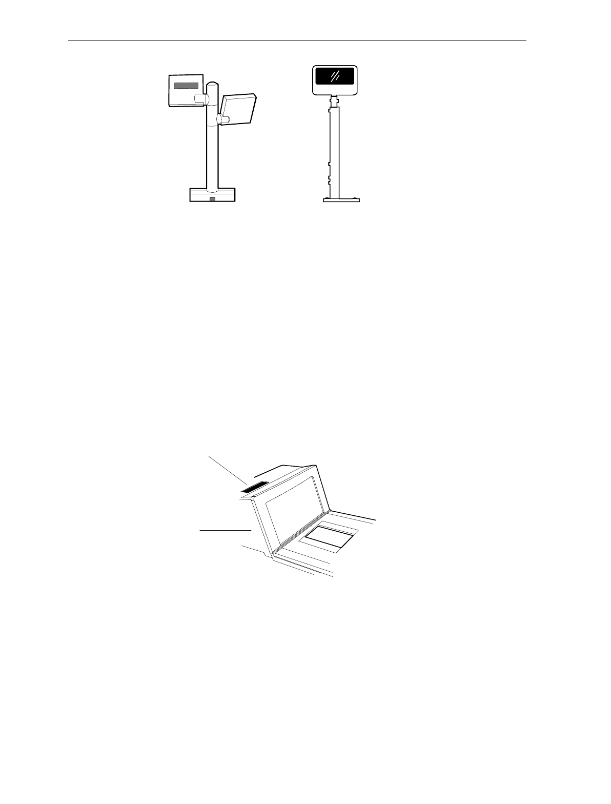
2-4 Chapter 2: Features, Functions, and Kits
16345
NCR 7825 Remote
Post Display
NCR 7825 Remote
Compact Display
Depending on the checkstand construction, a keyboard may be
mounted above the 7870, which will obstruct the view of the integrated
display. In this case, it may be advantageous to install an NCR 7825
Post Mounted Display, which can be used with or without an
integrated display.
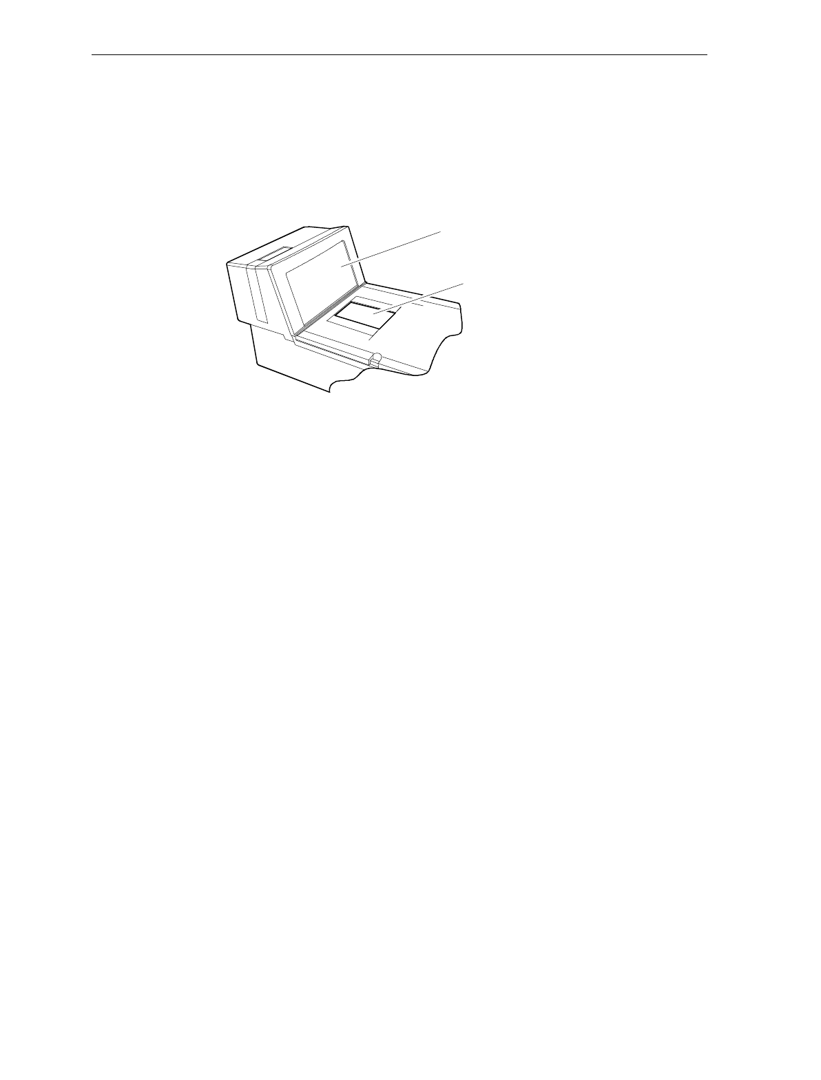
Integrated Display
The integrated display is an inset, LCD located on the top surface of the
tower. Depending on the checkstand design, the integrated design
may or may not be appropriate.
16819
Integrated Display
Tower

Chapter 2: Features, Functions, and Kits 2-5
No Display
If the 7870 is ordered with no display, the scale information is usually
displayed on the host terminal display. Please note, the host terminal
must be approved to perform a live/gross scale weight. This
arrangement is not available in all host terminals and some Weight and
Measures authorities do not permit this arrangement.
Interface TypesThe NCR 7870 communicates with the host terminal through various
types of interfaces. The 7870 Scanner always uses one interface cable.
However, some host terminals require dual cables for and NCR 7870
Scanner/Scale. See the Interface Cables section in Chapter 3: Site
Preparation for available interface cables.
Laser Scanner The 7870 operates with the performance of two scanners yet the bi-
optic scan pattern is created by a single laser and spinner motor. A 24 -
line convergent scan pattern (12 lines per scan window) is generated by
the laser diode. A 3-Phase, DC, brushless motor spins a tetrahedral
mirror at 6000 RPMs. The laser beam is reflected onto the stationary
mirrors in the Optics Assembly and then out the Scan Windows. The
Spinner Motor provides a scan speed of 2400 scan lines (100 scan
frames) per second. This enables the 7870 to read at a continuous item
speed of 2.0 meters per second. An experienced checker scans at a rate
of 0.8 to 1.0 meters per second, so the 7870 is able to keep up with high
volumes and fast checkers.
Power Supply A universal, switching Power Supply is used to provide DC voltage. It
has a replaceable, 3 m (10 foot) cord for connection to the power outlet
or source. A low voltage power cable connects the Power Supply to
the unit. The Power Supply can be fixed to the unit’s chassis on or
located on the floor or checkstand in the NCR 7870-1000 and 2000. For
other models, the Power Supply must be installed in the checkstand.
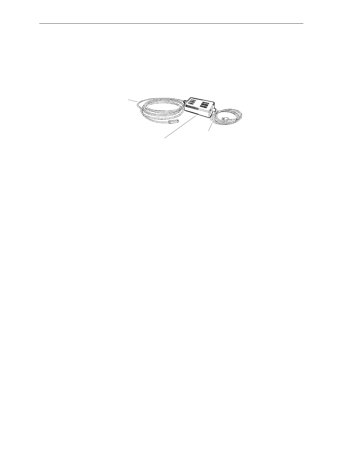
2-6 Chapter 2: Features, Functions, and Kits
An outboard power supply permits the 7870 to operate without
checkstand ventilation. The Power Supply accepts input line voltages
from 90 to 260 VAC at a frequency range of 47 to 63 Hz.
For a list of Power Cables and Cords, see the Cables Lengths and Hole
Sizes section in Chapter 3: Site Preparation.
Power Cable
(To AC)
Power Cord (To Unit)
Outboard Power Supply
16822
Programming the 7870
The NCR 7870 is featurized to fit a customer’s needs by using
programming tags which alter the unit’s operating parameters.
Following are some of the more common parameters which may be
adjusted:
• Communications Protocol • Code 39
• Good Read Tone • Code 128
• Not-On-File Tone Volume • RS-232
• Timers • Interleaved 2 of 5
• UPC/EAN • PACESETTER Plus
• Add-On Code • Label Identifiers

Chapter 2: Features, Functions, and Kits 2-7
Scale Certifications
Scale certifications are available for these markets:
Market 9.95 kg 13.995 kg 30 lb.
Argentina •
Australia ••
Brazil •
California •
Canada •••
Czech Republic •
Europe •
Hong Kong ••
Indonesia •
International •
Mexico •
New Zealand ••
People’s Republic of China •
Russia Federation •
United Kingdom •
U.S. •
Venezuela •
Vietnam •

2-8 Chapter 2: Features, Functions, and Kits
Scan Zone The scan lines are dispersed in a forward and backward direction from
both windows. This allows the scanner to read a) on four sides, b)
from left-to-right or right-to-left, and c) inverted labels. If the scan
zone is thought of as a cube resting on the horizontal scan window, the
scanner is able to read the leading, trailing, bottom, and far surfaces.
Another way of describing the scan zone is – if the checker can’t see the
bar code label, then the scanner can. The scan zone extends to 20.3 cm
(8 in.) high off the horizontal window. Bi-optical scanning makes the
scan zone large enough to allow a label to be read off of a tall soup can
even when upside-down
Scanner Power Requirements
The laser diode occupies little space, draws low current, and produces
little heat. The light produced by the scanners in current models has
been shifted toward the edge of the visual spectrum so it is not possible
to see the scan pattern in normal lighting. When active, the laser uses
22 watts. A soft power down feature allows major portions of the 7870
to shut down when no motion is detected. While in sleep mode, the
scanner’s power requirements drop to 10 watts, a 65% reduction. A
more valuable advantage of the soft power down feature is the run
time reduction of critical components which translates directly into
extending the life of the scanner. The scanner automatically powers up
after detecting motion in approximately two seconds.
Soft Power Down
During periods of inactivity, components of the scanner and scale shut
down to conserve power, reduce wear, and extend product life. A
motion sensor detects activity and signals the unit to power up from
sleep mode. The power up takes less than two seconds.
Chapter 2: Features, Functions, and Kits 2-9
Top Plates and Scan Windows
Top Plates
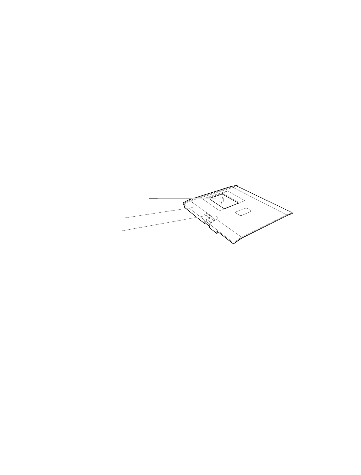
A Top Plate provides a snag-free place to scan items and protects the
internal components from contamination and liquid spills. It has an
inset Lift Tab (older units may have two) which permit the Top Plate to
be quickly removed or replaced with no tools. The scan window inset
in the Top Plate is either diamond-coated (replaceable) or sapphire
glass (permanent). When a unit has a scale, the Top Plate becomes a
part of the scale system – the scale must be recalibrated when the Top
Plate or any of its components, such as the scan window, are replaced.
The current line of 7870 Scanners and Scanner/Scales have been
upgraded to come with the Stainless Steel Top Plate as a standard
feature. Older 7870 units may have the painted steel Top Plate which
is no longer available.
Top Plate
Lift Tab
Slot (Horizontal) Scan
Window
Slot Scanner Window
The (horizontal) scan window is mounted in the Top Plate. The
window (if diamond-coated) is replaced by removing the Top Plate,
snapping out the old window, and snapping the new window in place.
The slot scanner window is available as diamond-coated glass or
sapphire glass. Diamond-coated glass was formerly known as
“scratch-resistant” glass. Sapphire glass is the upgrade and was
formerly known as “scratch-proof” glass. Other glass options such as
“hardened” and “armor” glass have been discontinued.
2-10 Chapter 2: Features, Functions, and Kits
Side Scanner Window
The NCR 7870 vertical scan window is mounted in a tower that rises
above the checkstand surface. The scan window can be removed from
the unit for cleaning. The upper console containing the scan window is
designed to withstand occasional impacts.
Side (Vertical) Scan Window
Slot (Horizontal) Scan Window
16821

Chapter 2: Features, Functions, and Kits 2-11
Scale Features and Functions
The scale is used in the 2000, 4000, and 4500 models. It can be
manufactured by NCR or by a vendor for a specialized market such as
the price-computing scale in the 4500 model to meet European
standards.
Scale Functions and Features
Load Cell
The NCR 7870 uses a single load cell rather than four, which is more
typical, to increase reliability. The scale has a settling time of 0.9
seconds for items weighing less than 2.3 kg (5 lbs.) It is sealed to avoid
damage from spills around the unit. There are three basic types of load
cells:
• For weighing in pounds. Capacity: 30 lbs.
• For weighing in kilograms. Capacity: 9.995 kg
• For weighing in kilograms. Capacity: 13.995 kg
Reset / Scale Zero
A front-mounted Scale Reset button is located on the front bezel, to the
left of the vertical scan window. This flush membrane switch will reset
the scale due to fluctuation from extreme temperature drift, impact, or
scale tare up to:
1. 0.3 kg (0.6 lbs.) relative to the zero established during the most
recent power-on sequence
or
2. 0.6 kg (1.2 lbs.) relative to the calibration zero, whichever is less.
The scale reset function is completed in less than a second.
Auto-Zero
Scale electronics automatically tracks out stable shifts due to
temperature changes and compensates in 3 g (0.006 lb.) increments up
to a maximum of 0.3 kg (0.6 lbs.).

2-12 Chapter 2: Features, Functions, and Kits
Kits
Kit Name Kit Type Available for
Enhanced Scratch Resistant
Window
7870-K002-V001
Hardware 7870-1000
7870-2000
Upper Windows (Qty: 5)
7870-K003-V001 Hardware All
Stainless Steel Top Plate
7870-K005-V002 Hardware 7870-1000
7870-2000
Scale Shell Model
7870-K007-V001 Hardware N/A
Digital Board Upgrade (Board,
Firmware)
7870-K100-V001
Hardware,
Firmware All
Requirements: For units with S/Ns below 50-28901727, adds Speech
and Coupon Add-On Code.
PACESETTER Plus Upgrade
(OCIA/IBM)
7870-K401-V001, -V002
Firmware All
Requirements: V001 supports
units with S/Ns 50-28901727
or lower. V002 supports units
with S/Ns 50-00000000 and
higher.

Chapter 2: Features, Functions, and Kits 2-13
Kit Name Kit Type Available for
PACESETTER Plus Upgrade
(RS-232/Datachecker)
7870-K402-V003, –V002, -V003
Firmware All
Requirements: V001 supports units with S/Ns 50-28901727 or lower.
V002 supports units with S/Ns 50-00000000 and higher. V003 has a
PACESETTER Plus trailer fix.
Multi-Symbol Upgrade
7870-K404-V002 Firmware All
Requirements: For units with S/Ns 50-28901727 and higher. If
upgrading a unit with a lower S/N, install kit 7870-K100.
13.995 kg Upgrade
7870-K440-V001 Firmware,
Hardware 7870-2000
Requirements: For upgrade from 9.995 kg to 13.995 kg on units with
S/Ns 50-28901727 and higher. To upgrade a unit with a lower S/N,
install kit 7870-K100.
OCIA/IBM Interface – Single
Cable
7870-K450-V001, -V002
Hardware,
Firmware All
Requirements: V001 supports units with S/Ns 50-28901727 or lower.
V002 supports units with S/Ns 50-00000000 and higher.
OCIA/Interface – Dual Cable
7870-K451-V001, -V002 Hardware,
Firmware 7870-2000
Requirements: V001 supports units with S/Ns 50-28901727 or lower.
V002 supports units with S/Ns 50-00000000 and higher.

2-14 Chapter 2: Features, Functions, and Kits
Kit Name Kit Type Available for
RS-232 Interface (Board,
Firmware)
7870-K452-V003
Hardware,
Firmware All
Requirements: V001 supports units with S/Ns 50-28901727 or lower.
V002 supports units with S/Ns 50-00000000 and higher. V003
enhances the old digital board firmware.
Datachecker, 2170, ICL MDL,
ICL 9518/9535, SASI Interface
7870-K455-V001, -V002, -V003
Hardware,
Firmware All
Requirements: Kit is for interfacing with these host terminals: NCR
2170 (RS-232, Weightronix Emulation), Avery Emulation (RS-232),
Datachecker (RS-422), ICL MDL, ICL 9518, ICL 9535 (ICL Team POS
5000), SASI.
V001 supports only ICL T2001, V002 supports units with S/Ns 50-
28901727 or lower. V003 supports units with S/Ns 50-00000000 and
higher.
Non NCR OCIA
7870-K457-V002 Hardware,
Firmware All
Requirements: V001 supports units with S/Ns 50-28901727 or lower.
V002 supports units with S/Ns 50-00000000 and higher.
Casio and TEC Scale Interface
7870-K458-V003 Hardware,
Firmware 7870-2000
Requirements: V001 supports units with S/Ns 50-28901727 or lower.
V002 supports units with S/Ns 50-00000000 and higher. V003
supports the same as V002 plus TEC.

Chapter 2: Features, Functions, and Kits 2-15
Kit Name Kit Type Available for
IBM 4682/4693/4694 Standard
Interface and IBM 4682-4B Full
ASCII Interface
7870-K459-V002
Hardware,
Firmware All
Requirements: V001 supports units with S/Ns 50-28901727 or lower.
V002 supports units with S/Ns 50-00000000 and higher.
Datachecker 2000 Interface
7870-K463-V001 Hardware All
Requirements: 7870 must be configured for Single-Cable, OCIA.
Dual Cable RS-232 Interface for
I/F 1
7870-K465-V001
Hardware,
Firmware 7870-2000
Requirements: 7870 must be configured for OCIA or IBM
communications. Avery Emulation (RS-232), Weightronix Emulation
(RS-232) for scanners with an I/F 1 Interface Board.
Australia with I/F 1 Interface
to 2126 Dual Cable 13.995 kg
(Coles)
7870-K466-V001
Hardware,
Firmware 7870-2000,
kg units only
Requirements: For upgrading units with a) S/Ns 50-28901727 and
higher and b) I/F 1 Interface Board from 9.995 kg to 13.995 kg. To
upgrade units with lower S/Ns, kit 7870-K100 must also be installed.
If the unit has an I/F 2 Interface Board, kit 7870-K450 must also be
installed.
Integrated Display
7870-K480-V001 Hardware All

2-16 Chapter 2: Features, Functions, and Kits
Kit Name Kit Type Available for
Top Plate with Scratch-Proof
Window (Standard size)
7870-K601-V001
Hardware 7870-1000
7870-2000
Top Plate with Scratch-Proof
Window (Compact)
7870-K605-V001
Hardware 7870-3000
WalMart/Argentina Upgrade
7870-K846-V001 Hardware,
Firmware 7870-2000
Requirements: To upgrade a 9.995 kg scanner/scale to Argentina
requirements, unit must have a) S/N 50-28901727 or higher and b) an
NCR 7825 Remote Display.
Coupon Add-On Code
Upgrade
7870-K850-V001
Firmware All
Requirements: For units with S/Ns between 50-28901727 and 50-
31148616. For units with S/Ns 50-2891727, use kit 7870-K100. For
units with S/Ns 50-31148616 and larger, no kit is needed – enable
feature through programming options.
Checkpoint Scanner Bezel
7870-K896-V001 Hardware 7870-1000
7870-3000
Requirements: A Checkpoint representative must make the final
connection from the 7870 to the Checkpoint equipment after kit
installation.

Chapter 2: Features, Functions, and Kits 2-17
Kit Name Kit Type Available for
Checkpoint Scanner/Scale
Bezel
7870-K898-V002, -V003
Hardware
Requirements: Kit is mandatory for upgrading to Checkpoint on units
with S/N 50-32573274 or lower. For units with higher S/Ns, may use
this kit or kit 7870-K899-V001. V002 is for use in U.S. and Mexico
only. A Checkpoint representative must make the final connection
from the 7870 to the Checkpoint equipment after kit installation.
Checkpoint Scanner/Scale
Bezel
7870-K899-V001
Hardware
Requirements: For units with a S/N 50-32573274 and higher. For
units with a lower S/N, install kit 7870-KK898-V003. A Checkpoint
representative must make the final connection from the 7870 to the
Checkpoint equipment after kit installation.

2-18 Chapter 2: Features, Functions, and Kits

Chapter 3: Site Preparation
For the NCR 7870 to operate efficiently and safely, the selected
installation site must meet certain requirements. Ensuring that these
conditions are met and maintained will protect the 7870 from
unnecessary wear and potential damage as well as easing installation.
This chapter covers
• Getting Started
• About Site Preparation
• Customer Responsibilities
• Environmental Requirements
• Checkstand Power and Wiring Considerations
• Checkstand Considerations
• Cable Lengths and Hole Sizes
• 7870 Dimensions

3-2 Chapter 3: Site Preparation
Getting Started
The first step to preparing the selected site is to read the following two
sections – About Site Preparation and Customer Responsibilities.
These sections provide important information about NCR’s and your
responsibilities to keep the NCR 7870 safe and in good working order.
The next step is to evaluate the chosen site for its suitability. As a
minimum, these conditions need to be accessed:
• Is the environment controlled within the 7870’s operational range
for temperature, temperature change, relative humidity, barometric
pressure, ambient light, acoustic noise, vibration, and shock?
• Will other electronics be placed in checkstand which could
necessitate use of forced air to regulate the temperature?
• Will the power circuit to supply the 7870 be
• dedicated to NCR equipment only and so labeled,
• equipped with an isolated, insulated ground,
• providing the required input to the Power Supply,
• equipped with a recessed, 15-amp circuit breaker convenient to
the checker, and
• equipped with protection against voltage transients?
• Is the checkstand
• able to securely support the weight of the 7870 and
• properly ventilated?
• Has the plan for the checkstand design considered
• use of a diverter or an adjustable plate,
• clearance needed for service and customer viewing of display,
• location and size of hole for cable routing, and
• providing enough slack in cables so 7870 may be removed from
checkstand for service without disconnection?

Chapter 3: Site Preparation 3-3
The following sections contain the NCR 7870’s requirements. These
specifications will allow you to evaluate the site for installation.
The last step is to implement the necessary changes before beginning
the installation process described in Chapter 4: Installation.

3-4 Chapter 3: Site Preparation
About Site Preparation
This chapter contains the information necessary for the preparation of a
site conforming to NCR specifications. It is very important that the site
complies with the requirements in this document because, once the
equipment has been installed, deficiencies in site preparation or the
problems caused by these deficiencies are much more difficult to detect
or correct. Further, failure to comply with these requirements or to
take proper steps to protect equipment against risks identified in this
document may cause serious damage to the equipment and to the
customer’s business.
In addition to the need to comply with the requirements specified,
electrical wiring and mechanical systems must also comply with all
relevant codes, laws, and regulations.
It is important that the site be prepared by a customer or a customer
agent who is fully conversant with the special requirements of
electronic equipment. The responsibility of ensuring that the site is
prepared in compliance with this document remains with the
customer.
For information and guidance purposes only, a list is provided, in
general terms, of these matters for which the customer is responsible.
This list is not intended to be comprehensive, and in no way modifies,
alters, or limits the responsibility of the customer for all aspects of
adequate site preparation.
NCR staff is available to answer questions relating to the contents of
this document, but except where:
a) the customer has been notified that a full or partial consultancy
service is available and/or that NCR is willing to undertake a
preliminary or final site survey and
b) the customer shall have entered into a formal contract with
NCR for provision of the same.

Chapter 3: Site Preparation 3-5
No comment, suggestion, or advice offered or not offered about
preparation of the site nor any inspection of the site whether before or
after preparation is to be taken as approval of the location of the site
and equipment or of its preparation, and NCR is not liable in respect of
any comment, suggestion, or advice given by its staff or in respect of
any failure to give advice.
Finally, only the customer can know the full extent of damage which
may be caused to his business by reason of failure of the equipment
which is to be installed. For this reason, it is the customer’s
responsibility to ascertain the extent of any such possible damage to his
existing or planned business, and to effect full insurance in respect of it.

3-6 Chapter 3: Site Preparation
Customer Responsibilities
The customer must do or provide the following.
• When required by NCR, provide the NCR Customer Services
Representative with appropriate drawings that indicate
• location of equipment,
• site wiring (power and signal, paths, and lengths),
• Location of other equipment capable of generating large
amounts of electrical noise, electromagnetic interference,
heat, and so on.
• Provide floor coverings and environmental systems that
prevent static electricity build-up and discharge.
• Provide and install necessary power distribution boxes,
conduits, grounds, lightening arrestors, and associated
hardware.
• Make sure clear space and environmental requirements of the
unit are met.
• Make all building alterations necessary to meet wiring and
other site requirements.
• Make sure all applicable codes, regulations, and laws
(including, but not limited to, electrical, building, safety, and
health) are met.
• Provide and install all communication cables, wall jacks, special
connectors, and associated hardware.
• Provide and install auxiliary power or other equipment as
required.

Chapter 3: Site Preparation 3-7
Environmental Requirements
Operating Range
Condition Range
Temperature 10° C – 40° C(50° F – 104° F)
Temperature Change 10° C per hour (18° F per hour)
Relative Humidity 5% to 95%, Non-Condensing
Barometric Pressure 79.5 x 10³ Pa to 105 x 103 Pa
Ambient Light 200 Foot-candles max (2152 Lux)
on both scanner windows
Acoustical Noise 55 dBa or less
Vibration and Shock 1 to 10 Hz with a double amplitude of
0.127 cm (0.05 in.)
10 to 300 Hz with a maximum of 0.25 gee
Extreme Operating Range
Condition Range
Temperature -15° C to 45° C (5° F to 113° F)
one hour max
Temperature Change 20° C per hour (36° F per hour)
Relative Humidity 5% to 95%, Non-Condensing

3-8 Chapter 3: Site Preparation
Storage Range
Condition Range
Temperature -15° C to 50° C(5° F to 120° F)
Temperature Change 20° C per hour (36° F per hour)
Relative Humidity 5% to 95%, Non-Condensing
Transit Range
Condition Range
Temperature -40° C to 60° C (-40° F to 140 F)
Temperature Change 20° C per hour (36° F per hour)
Relative Humidity 5% to 95%, Non-Condensing
Barometric Pressure 74 x 103 Pa to 105 x 103 Pa

Chapter 3: Site Preparation 3-9
Checkstand Power and Wiring Considerations
Power Considerations
In the 1000 and 2000 models, the 7870 receives power from an external
supply which is normally mounted to the exterior surface of the unit’s
chassis. The power supply may be mounted near the 7870 rather than
on it, if advantageous.
In the 3000, 4000, and 4500 models, the power supply is mounted on
the checkstand.
It is a 40-watt switching power supply with the following inputs.
Voltage Frequency Input Power
90 to 260 Vac 47 to 63 Hz 55 Watts
Power Applications
The 7870 has no ON/OFF switch. A recessed, 15 amp circuit breaker
must be wired in the checkstand. This circuit breaker must be
accessible to the operator so the unit may be powered off and on. It
will also be needed to reset the unit during programming.
Power Transients Protection
Voltage transients -- surges, sags, impulses, and spikes – may be
experienced routinely or sporadically. When such conditions exist, the
use of protective devices may be required to ensure proper operation.
3-10 Chapter 3: Site Preparation
Wiring Considerations
U.S., Canadian, and Japanese Checkstand Wiring
Feeder wiring and insulated ground from
main service panel to distribution panel
to be run in metal conduit.
The electrical wiring must meet all
electrical codes, laws, and regulations.
Note:
Circuit Breakers
NCR circuits should be run in
separate metal Conduits.
Isolated/Insulated
Ground Bus
Isolated Ground Receptacles
Neutral and
Ground Bus
Neutral
Bus
Input
Voltage
Input Voltage L1, L2 Circuit Breakers
U.S., Canada, &
Japan
European
International
100Vac to 120Vac
220Vac
220Vac to 240Vac
100Vac to 120Vac
220Vac
220Vac to 240Vac
Standard single-pole; value
determined by type of device
branch and by electrical code.
European double-pole.
Circuit B: Terminal
Installation Type
NCR circuits must be dedicated to
NCR equipment or other logically
connected electronic equipment
(modems, DAA, bridges, etc.)
Note:
Circuit C: Scanner/Scale
Receptacle should be easily
accessible and near the
Scanner/Scale
L2
L3
Distribution Panel
Main Service
Panel
Conduit
Checkstand
Frame
Circuit A: Checkstand
Belt
Motor
Belt Control
Lighting
Misc. Equip.
N
G
L1
R0121
Chapter 3: Site Preparation 3-11
European Checkstand Wiring
Use this diagram when line voltage to the Service Panel is 220 Vac and
European double-pole circuit breakers are used in the Distribution
Panel.
Belt
Motor
N
L3
Conduit
Belt Control
Lighting
Misc. Equip.
N
G
Feeder wiring and insulated ground from main
service panel to distribution panel to be run in
metal conduit.
The electrical wiring must meet state
and local electrical codes, laws, and
regulations.
European double-pole circuit breakers.
NCR circuits should be run
in seprate metal Conduits.
Isolated/
Insulated
Ground Bus.
L2 L1
Terminal
Distribution Panel
Isolated Ground
Receptacles
Checkstand
Frame
Store
Load Center
Scanner/Scale
Neutral and
Ground Bus
Neutral Bus NCR circuits must be dedicated to
NCR equipment or other logically
connected electronic equipment
(modems, DAA, bridges, etc.)
Note :
Circuit A
Circuit B
Circuit C
220Vac
220 Vac
R0133
3-12 Chapter 3: Site Preparation
International Checkstand Wiring
Use this diagram when the line voltage to the Service Panel is 220 or
240 Vac and standard single pole circuit breakers are used in the
Distribution Panel.
Belt
Motor
N
L3
Conduit
Belt Control
Lighting
Misc. Equip.
N
G
Feeder wiring and insulated ground from main
service panel to distribution panel to be run in
metal conduit.
The electrical wiring must meet state
and local electrical codes, laws, and
regulations.
Standard single-pole circuit breakers.
NCR circuits should be run
in seprate metal Conduits.
Isolated/
Insulated
Ground Bus.
L2 L1
Terminal
Distribution Panel
Isolated Ground
Receptacles
Checkstand
Frame
Main Service
Panel
Scanner/Scale
Neutral and
Ground Bus
Neutral Bus NCR circuits must be dedicated to
NCR equipment or other logically
connected electronic equipment
(modems, DAA, bridges, etc.)
Note :
Circuit A
Circuit B
Circuit C
220
240 Vac
220
230
240 Vac
R0134

Chapter 3: Site Preparation 3-13
Wiring Instructions
Running Feeder Lines from Main Service Panel
1. Select the most appropriate wiring diagram as a guide.
2. Run two separate feeder lines in conduit from the Main Service
Panel in the checkstand to the customer equipment and to the NCR
Distribution Panel.
• Line 1 services Circuit A which is for customer equipment such
as checkstand belt motor, counter lighting, and cooling fans.
• Line 2 is dedicated to service the NCR equipment, typically
Circuit B and Circuit C.
Circuit A
3. Electrically connect the grounding conductor in Circuit A to Store
Ground.
4. Electrically connect conduit and checkstand junction box to the
frame of the checkstand, if conductive, or to a common tie point if
not conductive.
5. Connect to the grounding conductor in Circuit A (which is Store
Ground) any
• conduit,
• metal parts,
• store ground devices
• counter belt motor ground, and
• other counter equipment grounds.

3-14 Chapter 3: Site Preparation
Circuit B
The ground conductor in Circuit B (to the host terminal) is an isolated,
insulated ground – it must be isolated from the outlet box for the host
terminal. The circuit breaker in the power conductor of Circuit B is
optional. If used, it should be near the operator and recessed.
Circuit C
The power conductor in Circuit C (to the NCR 7870) should include a
15 Amp circuit breaker located near the operator. The circuit breaker
should be recessed to prevent being accidentally switched on or off.
Note: The outlet boxes for the NCR equipment must be isolated and
insulated from the ground conductor, convenient to the equipment,
readily accessible, and labeled as exclusively for use with NCR
equipment.

Chapter 3: Site Preparation 3-15
Checkstand Considerations
Careful planning of how the checkstand and 7870 work together can
improve flow and ergonomics. An evaluation of the checkstand
should take into consideration:
• weight of the 7870,
• ventilation,
• service clearance to the 7870,
• display clearance,
• power on and off,
• secure fit and mounting in the cutout for the 7870,
• item diverter (optional),
• adjustable plate (optional),
Ventilation Requirements
The NCR 7870 Scanner/Scale does not need an exhaust fan in the
checkstand provided
• there is adequate convection air flow,
• no other equipment in the checkstand raises the temperature in the
checkstand to more than 7° C (12.6° F) above the ambient
temperature, and
• the temperature inside the checkstand does not exceed 40° F.
If the checkstand contains other heat producing equipment, forced air
may be needed to keep the temperature within the 7870’s operating
range. If forced air is used, air coming into or leaving the checkstand
MUST NOT enter or exit past the 7870.
3-16 Chapter 3: Site Preparation
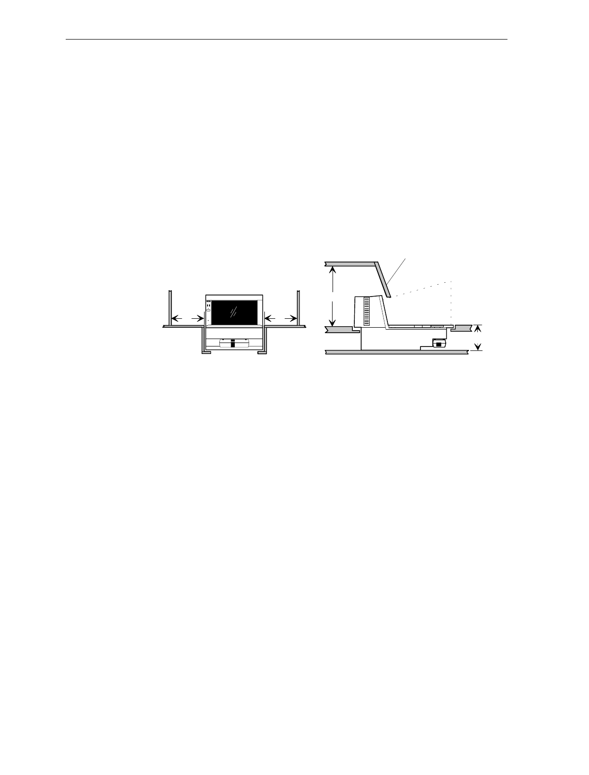
Service Clearance
The 7870 is designed to allow servicing without removal from the
checkstand. This includes component removal and replacement, scale
calibration, and installation of the Weights and Measures seal. To take
advantage of this design feature, an area for service clearance must be
provided.
Note: Access to the Power Supply may require removal of the 7870
from the checkstand.
A = 20.3 cm (8.0 in.) minimum if checkstand structure is not removable for servicing.
2.5 cm (1.0 in.) minimum if checkstand structure is removable for servicing.
B = 33.0 cm (13.0 in.) minimum if checkstand structure is not removable for servicing.
17.8 cm (7.0 in.) minimum if checkstand structure is removable for servicing.
C = 13.0 cm (5.1 in.) minimum clearance to closest checkstand panel. The 7870-1000
or 2000 must not be supported by this panel.
Mounting surface for keyboard must
be removable for servicing and
vertical window replacement.
AA
C
BItem Flow Area
R0117
Chapter 3: Site Preparation 3-17
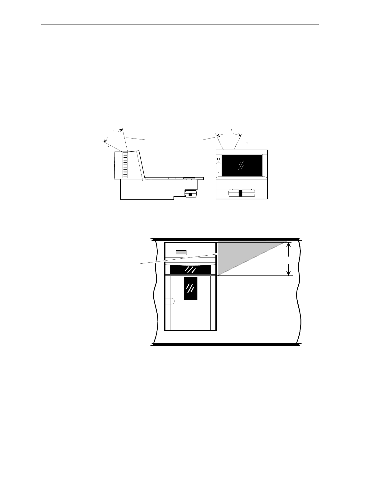
Display Clearance
If the 7870 Scanner/Scale has an integrated display, there must be
adequate clearance for viewing by the customer. In the U.S. , this is a
Weights and Measurements requirement. International countries
should check with their appropriate local or government agency. If the
checkstand design restricts viewing, the NCR 7825 Remote Display
may be used to meet visibility requirements.
30
This area must be clear
for viewing integrated display. 60
50 60
R0118
Item Diverter
R0131
7.25 in. (18.4 cm)
Item Diverter
(Must be removable
to service
Scanner/Scale in
Checkstand)
3-18 Chapter 3: Site Preparation
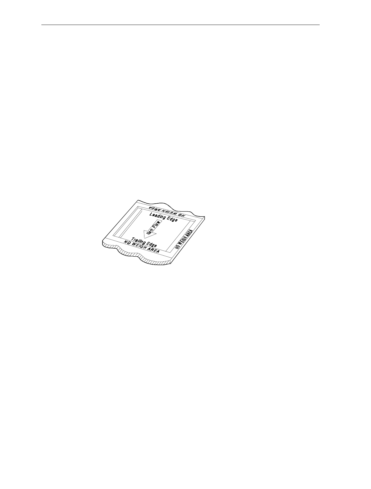
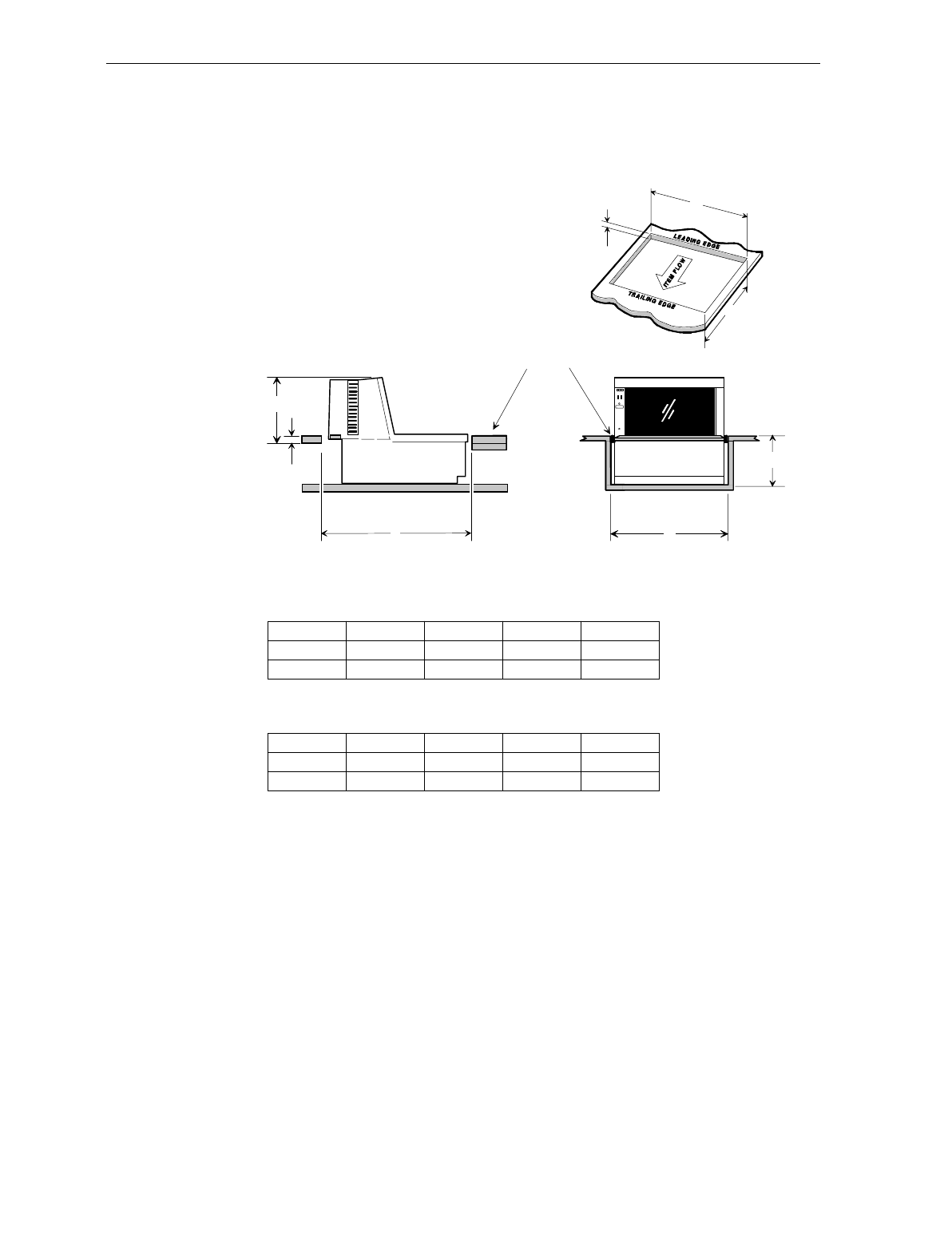
Checkstand Hole
When cutting the checkstand hole, also called a cutout, take care to
maintain the specified dimensions. While this is essential for all
models, it is critical for units with a scale.
• For all models, the leading edge of the Top Plate must be flush or
no more than 15 cm (0.06 in.) below the top of the checkstand. The
trailing edge of the Top Plate must be flush with the top of the
checkstand.
• For proper scale operation, the clearance between leading and
trailing edges of the Top Plate and the checkstand must be
maintained.
• For European installations, a 5.1 cm (2 in.) border must be provided
around the leading edge, trailing edge, and operator side of the
scanner scale. This border must contain the words “NO WEIGH
AREA.”
99999
An NCR 7870-1000 may be placed in an existing cutout for an NCR
7820 and an NCR 7870-2000 may go into a cutout for the NCR 7824.
Before utilizing an existing cutout, you MUST ensure that the cutout
has the correct dimensions before installing the 7870.
Chapter 3: Site Preparation 3-19
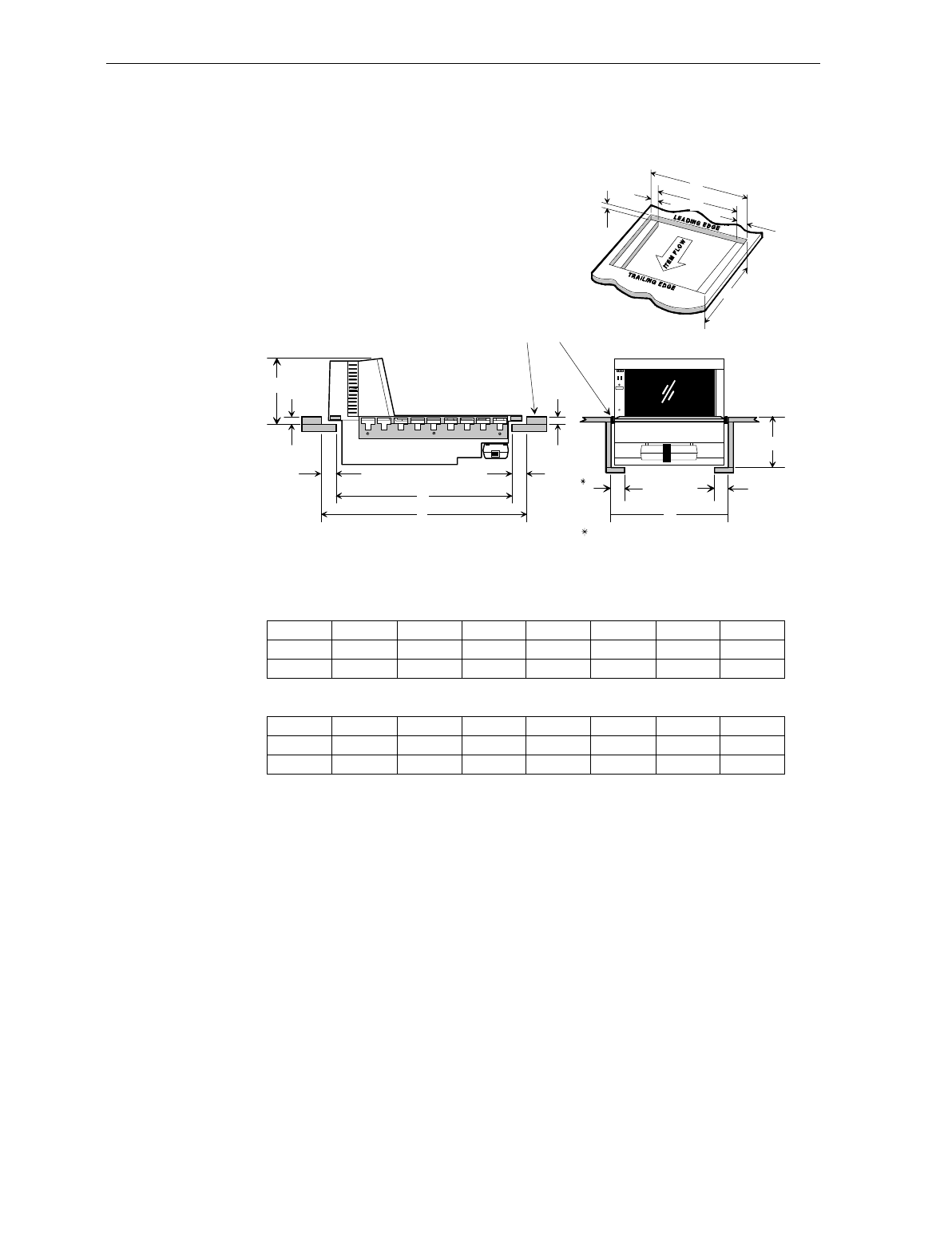
Checkstand Hole - Models 1000 & 2000
Recommended shelf to catch
NCR 7870 if dropped during
installation. The 7870 must
not be supported by this shelf.
Note: Spacers are to
position scale in hole.
They should be below
the Checkstand top.
No electronics under NCR 7870
D
C
C
A
B
E
R0119
NCR 7870-1000 Scanner
ABCDEFGH
11 5/8 in.
29.51 cm
20 1/16 in.
50.95 cm
1 3/8 in.
3.49 cm
3/8 in.
0.95 cm
17 5/16 in.
43.97 cm
1 3/8 in.
3.49 cm
5 1/8 in.
13.0 cm
6 1/4 in.
15.88 cm
CC
B
DD
E
H
F
G
F
A
NCR 7870-2000 Scanner/Scale
ABCDEFGH
12 in.
30.48 cm
20 1/16 in.
50.95 cm
1 3/8 in.
3.49 cm
1/2 in.
1.27 cm
17 5/16 in.
43.97 cm
1 3/8 in.
3.49 cm
5 1/8 in.
13.0 cm
6 1/4 in.
15.88 cm
3-20 Chapter 3: Site Preparation
Checkstand Hole - Models 3000, 4000, & 4500
Note: Spacers are to
position scale in hole.
They should be below
the Checkstand top.
No electronics under the 7870
C
A
B
Note:
B
C
D
A
E
NCR 7870 - 3000 Scanner
A
29.51 cm
16631
NCR 7870 - 4000 & 4500 Scanner/Scale
The 7870-3000, 4000, and 4500 must sit on a shelf below the checkstand surface.
It cannot be suspended like the other units. Also, the shelf should be open at the
front and back.
BCDE
34.50 cm 0.95 cm 15.88 cm 12.54 cm
11 5/8 in. 13 5/8 in. 3/8 in. 6 1/4 in. 4 15/16 in.
A
29.51 cm
BCDE
43.97 cm 1.27 cm 15.88 cm 12.54 cm
12 .00 in. 17 3/8 in. 1/2 in. 6 1/4 in. 4 15/16 in.
29.51 cm
30.48 cm

Chapter 3: Site Preparation 3-21
Cable Lengths and Hole Sizes
When selecting a cable, take care to choose one with enough length for
easy routing to the NCR 7870. Also, include enough slack to allow the
unit to be lifted from the cutout without disconnecting the cables. This
will be beneficial while servicing the unit.
Minimum hole size data is provided for making openings to pass
cables through the checkstand. Ensure after drilling that there are no
sharp edges which may damage the cable.
The following charts provide cable length and hole size data for AC
Power Cords, DC Power Cables, Interface Cables, and Remote Display
Cables. The NCR 7870 can connect to any NCR Retail Terminal as well
as many competitive host terminals so a comprehensive list of interface
cables has been provided.
Cable Hole Diameters
Cable Minimum Hole Size
Power Cord – Outlet to Power Supply 3.18 cm (1.25 in.)
Power Cable – Power Supply to 7870 1.52 cm (0.60 in.)
Interface Cable 1.90 cm (0.75 in.)
Remote Display Cable 1.90 cm (0.75 in.)
DC Power Cable – Power Supply to 7870
Minimum Hole Diameter: 1.52 cm (0.60 in.)
Cable Cable Length
DC Power Cable 1.22 Meters (4 Feet)
Note: DC Power Cable length is not a factor if the Power Supply is
mounted on the chassis of the 7870 (Models 1000 and 2000 only).

3-22 Chapter 3: Site Preparation
AC Power Cords – Outlet to Power Supply
Minimum Hole Diameter: 3.18 cm (1.25 in.)
Cable Cable Length
US Standard 3.05 Meters (10 Feet)
US Twist-Lock 3.05 Meters (10 Feet)
International Pig-Tail 3.05 Meters (10 Feet)
Japan Standard 3.05 Meters (10 Feet)
Japan Twist-Lock 3.05 Meters (10 Feet)
Australia 3.05 Meters (10 Feet)
UK, Argentina 3.05 Meters (10 Feet)
Swiss 3.05 Meters (10 Feet)
Remote Display Cables
Minimum Hole Diameter: 1.90 cm (0.75 in.)
Display Cable Corporate ID Cable Length
7825 1416-C022-0040 4 m (13.1 ft.)
1416-C022-0080 8 m (26.2 ft.)
2552, 2557 1416-C068-0040 4 m (13.1 ft.)
1416-C068-0080 8 m (26.2 ft.)

Chapter 3: Site Preparation 3-23
Interface Cables - NCR Host Terminals
Minimum Hole Diameter: 1.90 cm (0.75 in.)
Host
Terminal Interface Cable Corporate
ID Part
Number Length
1255 OCIA Dual-Cable Scanner 1416-C026-0040 497-0300521 4 m (13.1 ft.)
Dual-Cable Scanner 1416-C026-0080 497-0300522 8 m (26.2 ft.)
Dual Cable Scale 1416-C027-0040 497-0300533 4 m (13.1 ft.)
Dual Cable Scale 1416-C027-0080 497-0300534 8 m (26.2 ft.)
2113 OCIA Scanner Only 1416-C230-0050 497-0302099 5 m (16.4 ft.)
2123 OCIA Dual-Cable Scanner 2123-K315 230-0113973
Dual-Cable Scale 2123-K315 230-0113973
2126 OCIA Dual-Cable Scanner 1416-C014-0040 497-0300361 4 m (13.1 ft.)
Dual-Cable Scanner 1416-C014-0080 497-0300362 8 m (26.2 ft.)
Dual-Cable Scale 1416-C015-0040 497-0300371 4 m (13.1 ft.)
Dual-Cable Scale 1416-C015-0080 497-0300372 8 m (26.2 ft.)
2127 OCIA Single-Cable 1416-C016-0040 497-0300310 4 m (13.1 ft.)
Single-Cable 1416-C016-0080 497-0300311 8 m (26.2 ft.)
2151, 2152 OCIA Scanner Only 1416-C234-0040 497-0402970 4 m (13.1 ft.)
2154, 2155 OCIA Single-Cable 1416-C012-0040 497-0300340 4 m (13.1 ft.)
2156, 2157 Single-Cable 1416-C012-0080 497-0300341 8 m (26.2 ft.)
Dual-Cable Scanner 1416-C012-0040 497-0300340 4 m (13.1 ft.)
Dual-Cable Scanner 1416-C012-0080 497-0300341 8 m (26.2 ft.)
Dual-Cable Scale 1416-C013-0040 497-0300350 4 m (13.1 ft.)
Dual-Cable Scale 1416-C013-0080 497-0300351 8 m (26.2 ft.)

3-24 Chapter 3: Site Preparation
Interface Cables – NCR Host Terminals (cont.)
Host
Terminal Interface Cable Corporate
ID Part
Number Length
2170 RS-232 Scanner Only 1416-C069-0040 497-0301380 4 m (13.1 ft.)
Scanner Only 1416-C069-0080 497-0301381 8 m (26.2 ft.)
Dual-Cable Scanner 1416-C069-0040 497-0301380 4 m (13.1 ft.)
Dual-Cable Scanner 1416-C069-0080 497-0301381 8 m (26.2 ft.)
Dual-Cable Scale 1416-C233-0040 497-0302149 4 m (13.1 ft.)
Dual-Cable Scale 1416-C233-0080 497-0302161 8 m (26.2 ft.)
2552 OCIA Dual-Cable Scanner 1416-C026-0040 497-0300521 4 m (13.1 ft.)
Dual-Cable Scanner 1416-C026-0080 497-0300522 8 m (26.2 ft.)
Dual-Cable Scale 1416-C028-0040 497-0300543 4 m (13.1 ft.)
Dual-Cable Scale 1416-C028-0080 497-0300544 8 m (26.2 ft.)
2557 OCIA Dual-Cable Scanner 1416-C026-0040 497-0300521 4 m (13.1 ft.)
Dual-Cable Scanner 1416-C026-0080 497-0300522 8 m (26.2 ft.)
Dual-Cable Scale 1416-C027-0040 497-0300533 4 m (13.1 ft.)
Dual-Cable Scale 1416-C027-0080 497-0300534 8 m (26.2 ft.)
2760 OCIA Single-Cable 1416-C011-0040 497-0300170 4 m (13.1 ft.)
Dual-Cable Scanner 1416-C011-0040 497-0300170 4 m (13.1 ft.)
Dual-Cable Scale 1416-C061-0040 497-0301144 4 m (13.1 ft.)
2950 OCIA Scanner Only 1416-C234-0040 497-0402970 4 m (13.1 ft.)
5932 RS-232 Scanner Only 1416-C239-0040 497-0407723 4 m (13.1 ft.)
7050, 7051 OCIA Single-Cable 1416-C012-0040 497-0300340 4 m (13.1 ft.)
Single-Cable 1416-C012-0080 497-0300341 8 m (26.2 ft.)
Dual-Cable Scanner 1416-C012-0040 497-0300340 4 m (13.1 ft.)
Dual-Cable Scanner 1416-C012-0080 497-0300341 8 m (26.2 ft.)
Dual-Cable Scale 1416-C013-0040 497-0300350 4 m (13.1 ft.)
Dual-Cable Scale 1416-C013-0080 497-0300351 8 m (26.2 ft.)

Chapter 3: Site Preparation 3-25
Interface Cables – NCR Host Terminals (cont.)
Host
Terminal Interface Cable Corporate
ID Part
Number Length
7052, 7053, OCIA Single-Cable 1416-C011-0040 497-0300170 4 m (13.1 ft.)
7054 Dual-Cable Scanner 1416-C011-0040 497-0300170 4 m (13.1 ft.)
Dual-Cable Scale 1416-C061-0040 497-0301144 4 m (13.1 ft.)
7058 OCIA Scanner Only 1416-C230-0050 497-0302099 5 m (16.4 ft.)
7070 OCIA Single-Cable 1416-C012-0040 497-0300340 4 m (13.1 ft.)
Single-Cable 1416-C012-0080 497-0300341 8 m (26.2 ft.)
Dual-Cable Scanner 1416-C012-0040 497-0300340 4 m (13.1 ft.)
Dual-Cable Scanner 1416-C012-0080 497-0300341 8 m (26.2 ft.)
Dual-Cable Scale 1416-C013-0040 497-0300350 4 m (13.1 ft.)
Dual-Cable Scale 1416-C013-0080 497-0300351 8 m (26.2 ft.)
7445 RS-232 Single-Cable 1416-C019-0040 497-0300422 4 m (13.1 ft.)
Single-Cable 1416-C019-0080 497-0300423 8 m (26.2 ft.)
7450 OCIA Single-Cable 1416-C011-0040 497-0300170 4 m (13.1 ft.)
Dual-Cable Scanner 1416-C011-0040 497-0300170 4 m (13.1 ft.)
Dual-Cable Scale 1416-C061-0040 497-0301144 4 m (13.1 ft.)
7452, 7453 RS-232 Single-Cable 1416-C019-0040 497-0300422 4 m (13.1 ft.)
Single-Cable 1416-C019-0080 497-0300423 8 m (26.2 ft.)
Interface Cables - Casio Host Terminals
Minimum Hole Diameter: 1.90 cm (0.75 in.)
Host
Terminal Interface Cable Corporate
ID Part
Number Length
2100 OCIA Dual-Cable Scanner 1416-C072-0040 497-0301403 4 m (13.1 ft.)
4-Bit Parallel Dual-Cable Scale 1416-C073-0040 497-0301404 4 m (13.1 ft.)

3-26 Chapter 3: Site Preparation
Interface Cables – Data Checker Host Terminals
Minimum Hole Diameter: 1.90 cm (0.75 in.)
Host
Terminal Interface Cable Corporate
ID Part
Number Length
2200 MDL/
Datachecker Single-Cable 1416-C144-0040 497-0301889 4 m (13.1 ft.)
T2001 MDL/
Datachecker Single-Cable 1416-C062-0040 497-0301152 4 m (13.1 ft.)
Interface Cables – Epson Host Terminals
Minimum Hole Diameter: 1.90 cm (0.75 in.)
Host
Terminal Interface Cable Corporate
ID Part
Number Length
Epson PC RS-232 Single-Cable 1416-C357-0040 497-0408212 4 m (13.1 ft.)
Interface Cables – Gilbarco Host Terminals
Minimum Hole Diameter: 1.90 cm (0.75 in.)
Host
Terminal Interface Cable Corporate
ID Part
Number Length
TCR-15 RS-232 Scanner Only 1416-C237-0040 497-0303139 4 m (13.1 ft.)

Chapter 3: Site Preparation 3-27
Interface Cables – IBM Host Terminals
Minimum Hole Diameter: 1.90 cm (0.75 in.)
Host
Terminal Interface Cable Corporate
ID Part
Number Length
4683, 4684 Single-Cable 1416-C020-0040 497-0300402 4 m (13.1 ft.)IBM 4683
Port 17 Single-Cable 1416-C020-0080 497-0300403 8 m (26.2 ft.)
IBM Port 9B Single-Cable 1416-C070-0040 497-0301390 4 m (13.1 ft.)
4682, 4683,
4684, 4693 Single-Cable 1416-C070-0080 497-0301391 8 m (26.2 ft.)
4683, 4684 OCIA Port
5B Single-Cable 1416-C142-0040 497-0301751 4 m (13.1 ft.)
4694 IBM Port 9E Single-Cable 1416-C070-0040 497-0301390 4 m (13.1 ft.)
Single-Cable 1416-C070-0080 497-0301390 8 m (26.2 ft.)
PC RS-232 9-pin Single-Cable 1416-C019-0040 497-0300422 4 m (13.1 ft.)
Single-Cable 1416-C019-0080 497-0300423 8 m (26.2 ft.)
Interface Cables – ICL Host Terminals
Minimum Hole Diameter: 1.90 cm (0.75 in.)
Host
Terminal Interface Cable Corporate
ID Part
Number Length
OCIA Scanner Only 1416-C264-0040 497-0404882 4 m (13.1 ft.)
Scanner Only 1416-C264-0080 497-0404883 8 m (26.2 ft.)
Dual-Cable Scanner 1416-C264-0040 497-0404882 4 m (13.1 ft.)
Dual-Cable Scanner 1416-C264-0080 497-0404883 8 m (26.2 ft.)
RS-232 Dual-Cable Scale 1416-C265-0040 497-0404918 4 m (13.1 ft.)
9518-01,
9518-21,
9518-61,
9518-62,
9518-71
Dual-Cable Scale 1416-C265-0080 497-0404919 8 m (26.2 ft.)

3-28 Chapter 3: Site Preparation
Interface Cables – ICL Host Terminals (cont.)
Host
Terminal Interface Cable Corporate
ID Part
Number Length
9518-200 Dual-Cable Scanner 1416-C140-0040 497-0301711 4 m (13.1 ft.)RS-232 9-Pin
D Shell Dual-Cable Scale 1416-C146-0040 497-0301931 4 m (13.1 ft.)
9520-150 Single-Cable 1416-C144-0040 497-0301889 4 m (13.1 ft.)
MDL/
Datachecker Single-Cable 1416-C144-0080 497-0301890 8 m (26.2 ft.)
MDL 9-Pin Single-Cable 1416-C260-0040 497-0404767 4 m (13.1 ft.)
9520-150
MDL Single-Cable 1416-C260-0080 497-0404766 8 m (26.2 ft.)
Dual-Cable Scanner 1416-C227-0040 497-0301031 4 m (13.1 ft.)
9520/
RS-232 RS-232 9-Pin
D Shell Dual-Cable Scale 1416-C226-0040 497-0302021 4 m (13.1 ft.)
RS-232 Single-Cable 1416-C019-0040 497-0300422 4 m (13.1 ft.)
Team POS
5000 Single-Cable 1416-C019-0080 497-0300423 8 m (26.2 ft.)
Interface Cables – Microbilt Host Terminals
Minimum Hole Diameter: 1.90 cm (0.75 in.)
Host
Terminal Interface Cable Corporate
ID Part
Number Length
8010 RS-232 6-Pin Scanner Only 1416-C326-0040 497-0407181 4 m (13.1 ft.)
Interface Cables – NEC Host Terminals
Minimum Hole Diameter: 1.90 cm (0.75 in.)
Host
Terminal Interface Cable Corporate
ID Part
Number Length
NEC
Terminal RS-232 Scanner Only 1416-C274-0040 497-0405139 4 m (13.1 ft.)

Chapter 3: Site Preparation 3-29
Interface Cables – SASI Host Terminals
Minimum Hole Diameter: 1.90 cm (0.75 in.)
Host
Terminal Interface Cable Corporate
ID Part
Number Length
1028 RS-232 Dual-Cable Scanner 1416-C342-0040 497-0407544 4 m (13.1 ft.)
Dual-Cable Scale 1416-C343-0040 497-4070545 4 m (13.1 ft.)
ex-10 RS-232 Dual-Cable Scanner 1416-C341-0040 497-0407543 4 m (13.1 ft.)
Dual-Cable Scale 1416-C343-0040 497-0407545 4 m (13.1 ft.)
RS-232 Dual-Cable Scanner 1416-C377-0040 497-0409575 4 m (13.1 ft.)ex-10 RXD
Enable Dual-Cable Scale 1416-C343-0040 497-0407545 4 m (13.1 ft.)
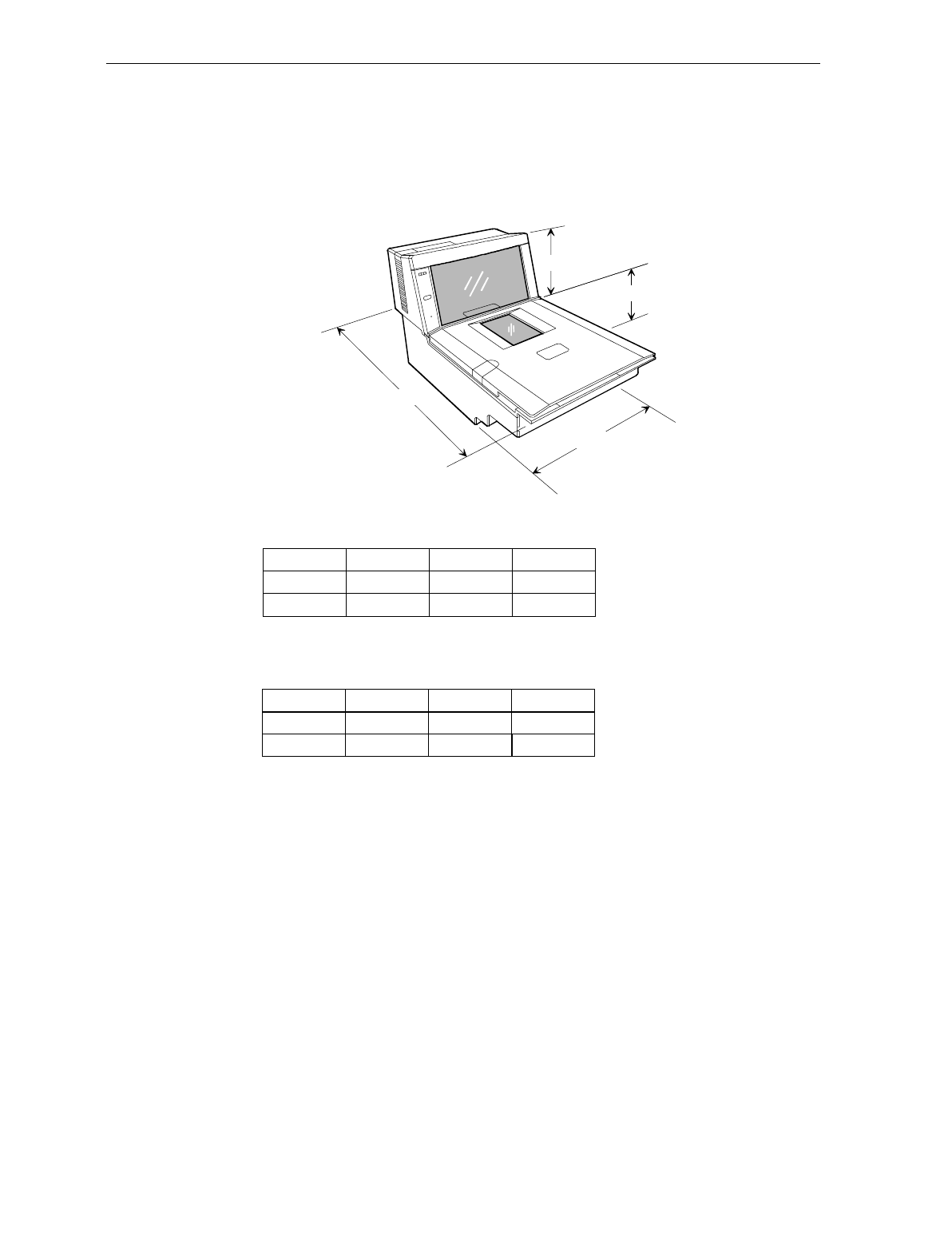
3-30 Chapter 3: Site Preparation
NCR 7870 Dimensions
NCR 7870-1000 & 2000 Models
NCR 7870 - 1000 Dimensions
A B C D
11 1/2" 5" 6"20"
51 cm 28.3 cm 13 cm 15.3 cm
A
B
C
D
NCR 7870 - 2000 Dimensions
A B C D
12" 5" 6"17 1/4"
43.8 cm 30.5 cm 13 cm 15.3 cm
16881
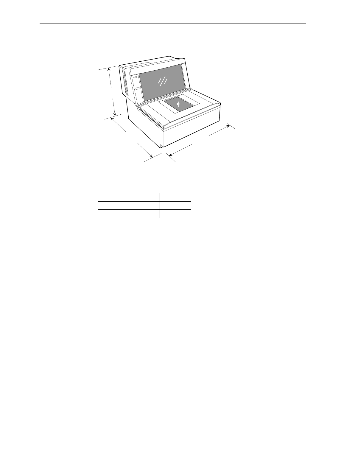
Chapter 3: Site Preparation 3-31
NCR 7870-3000 Model
C
B
A
NCR 7870 - 3000 Dimensions
A B C
11 5/16" 11 1/2"11"
28 cm 28.8 cm 28.2 cm
16879
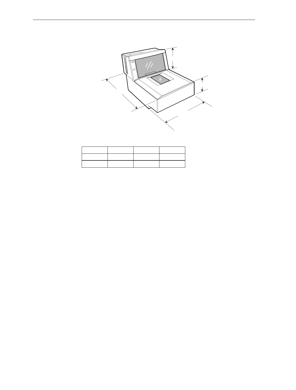
3-32 Chapter 3: Site Preparation
NCR 7870-4000 & 4500 Models
NCR 7870 - 4000 & 4500 Dimensions
A
B
C
D
AB C D
12" 5" 6"17 1/4"
43.8 cm 30.5 cm 13 cm 15.3 cm
16880

Chapter 4: Installation
Getting Started
This chapter describes the installation process for the NCR 7870.
Before installation, prepare the site in accordance to the requirements
in Chapter 2 – Site Preparation.
The first step is to perform an inspection to verify that the unit and
checkstand are ready.
Reporting a Damaged Unit
Upon receiving an NCR 7870, inspect the shipping for damage. If the
carton is damaged, open it in the presence of the shipping carrier
before signing the bill of lading. If the scanner/scale has been
damaged due to shipping, notify the carrier and an NCR
representative. If the unit was not purchased directly from NCR,
notify your supplier.
What’s in the Box
Unpack the unit according to the instructions on the box. Inventory
the contents to ensure you have received the following components.
• NCR 7870 • Power Cord
• Top Plate • Documentation
• Country Language Specific
IEC Class 1 Laser Labels
(International Units)
• Metal Foil Stamping Plate
(200x Model International
Units)
• Power Cord Documents
(International Units) • Interface Cable (when cable
feature requested with order)

4-2 Chapter 4: Installation
Cable Verification
The NCR 7870 can be used with many different host terminals. Verify
that you have received the correct interface cable (some set-ups require
two cables). A list of available interface cables is provided in the NCR
7870 Repair Guide (BD20-0966-A).
Checkstand Verification
Verify, as a minimum, that the checkstand is prepared according to the
following.
• Checkstand cutout is correct size.
• Display and service clearances are adequate.
• Checkstand is properly wired.
• Power cord is correct for unit and electrical outlet.

Chapter 4: Installation 4-3
Installing Unit in Checkstand
The NCR 7870 is fully assembled at the factory and requires no
operator assembly. The laser module is an integral part of the factory
assembled device and does not have any controls that can increase the
level of laser light or collateral radiation from the NCR 7870.
Instructions
Install Cables
1. Verify power receptacle switch is off.
2. Turn NCR 7870 on its side.
3. Route power cable through groove on bottom of unit.
4. Return unit to upright position.
5. Place unit so a portion of the tower is directly over the cutout in the
checkstand counter.
6. Pass Power Cord down through cutout and plug into dedicated
NCR power receptacle.
7. Connect communication interface cables to host terminal or PC.
Because installation varies from one terminal to another, refer to
your host terminal’s documents for specific information on
interface cable connection.
Note: A trained service technician may be required to open some
host terminals to connect the interface cables.
8. Connect interface cables to NCR 7870. Four interface connectors
are located on the rear side of the Tower Cabinet. These are for the
• REMOTE DISPLAY – used to connect the NCR 7825 Remote
Display, which is for price and weight information.
• SCANNER (or RS-232) – used to connect interface cable on
single cable installations or the scanner.
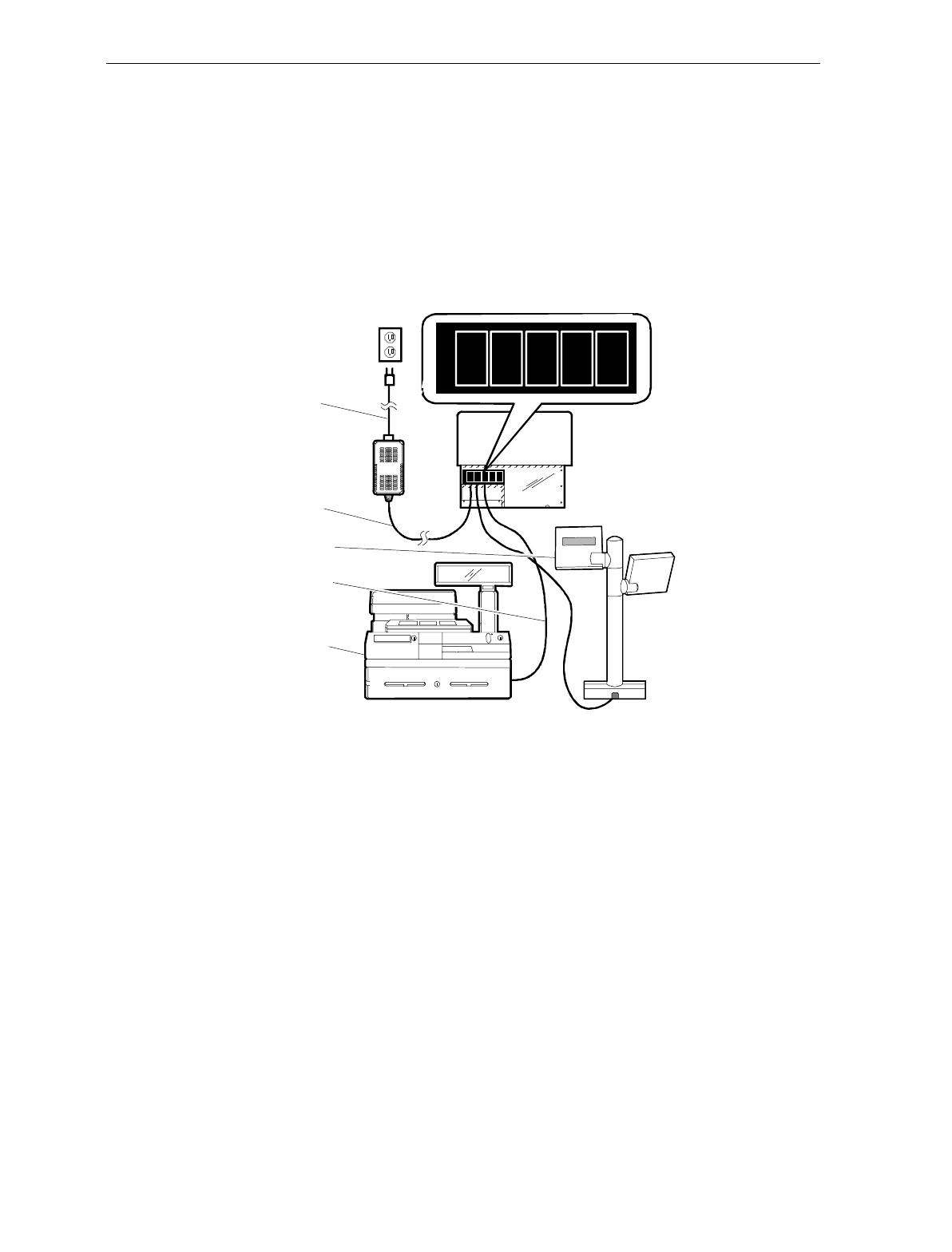
4-4 Chapter 4: Installation
• TERMINAL DISPLAY – Not used.
• SCALE (or Datachecker) – used to connect the scale interface
cable on dual cable installations.
9. See following diagrams for installation information for single, dual
cable, and Datachecker/RS-232 set-ups.
Single Cable Set-Up
DC
POWER
REMOTE
DISPLAY
SCANNER
TERMINAL
DISPLAY
SCALE
Power Cable
Power Cord
Interface Cable
Host Terminal
Remote Display
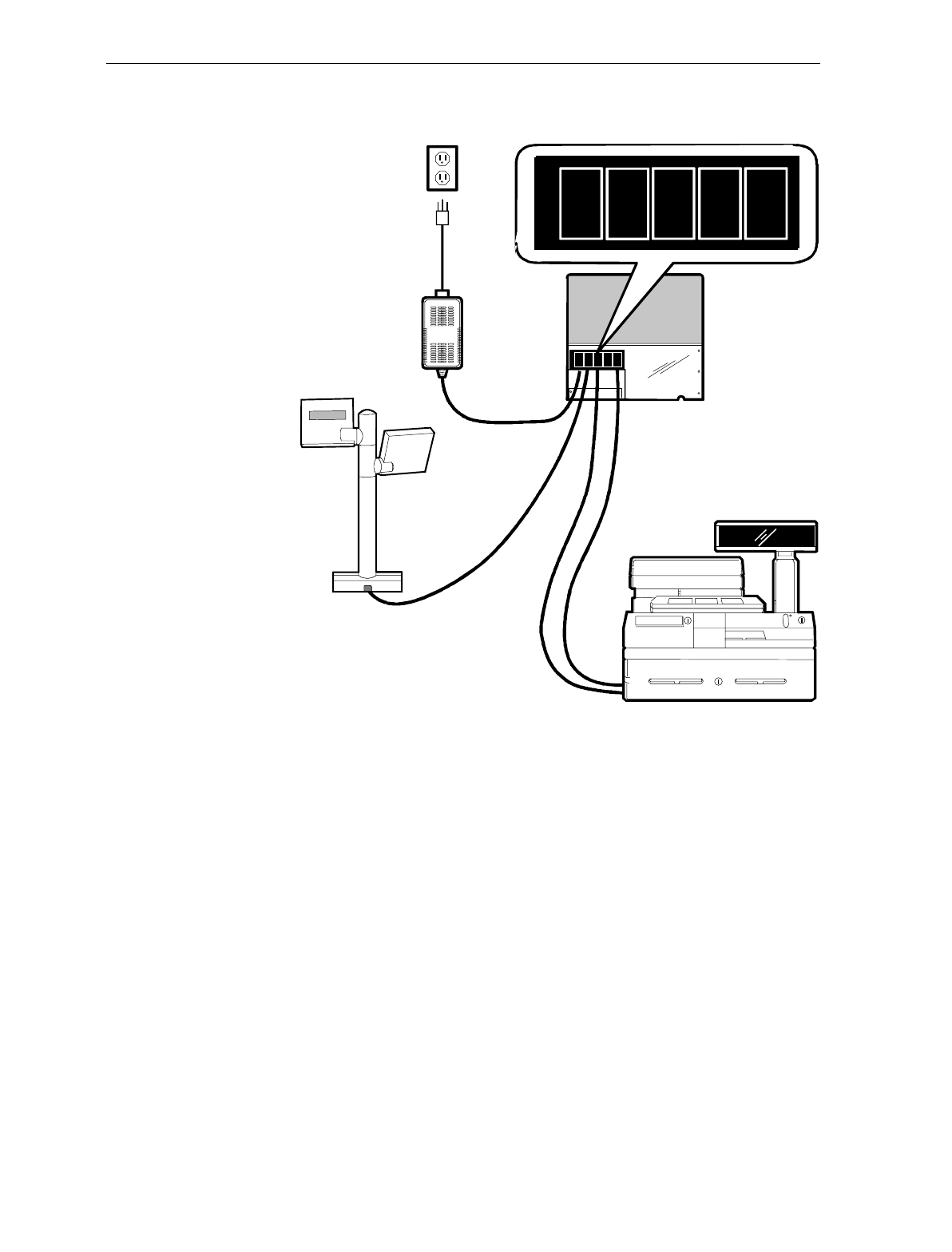
Chapter 4: Installation 4-5
Dual Cable Set-Up
AC
Power
Cord
DC Power Cable
7870
Scanner/Scale
Remote Display
Interface Cable
Power
Supply
Host Terminal
Interface Cable
Display Cable
DC
POWER
DISPLAY
OUTPUT
SCANNER
DISPLAY
INPUT
SCALE
DC
POWER
DISPLAY
OUTPUT
DISPLAY
INPUT
SCALE
SCANNER
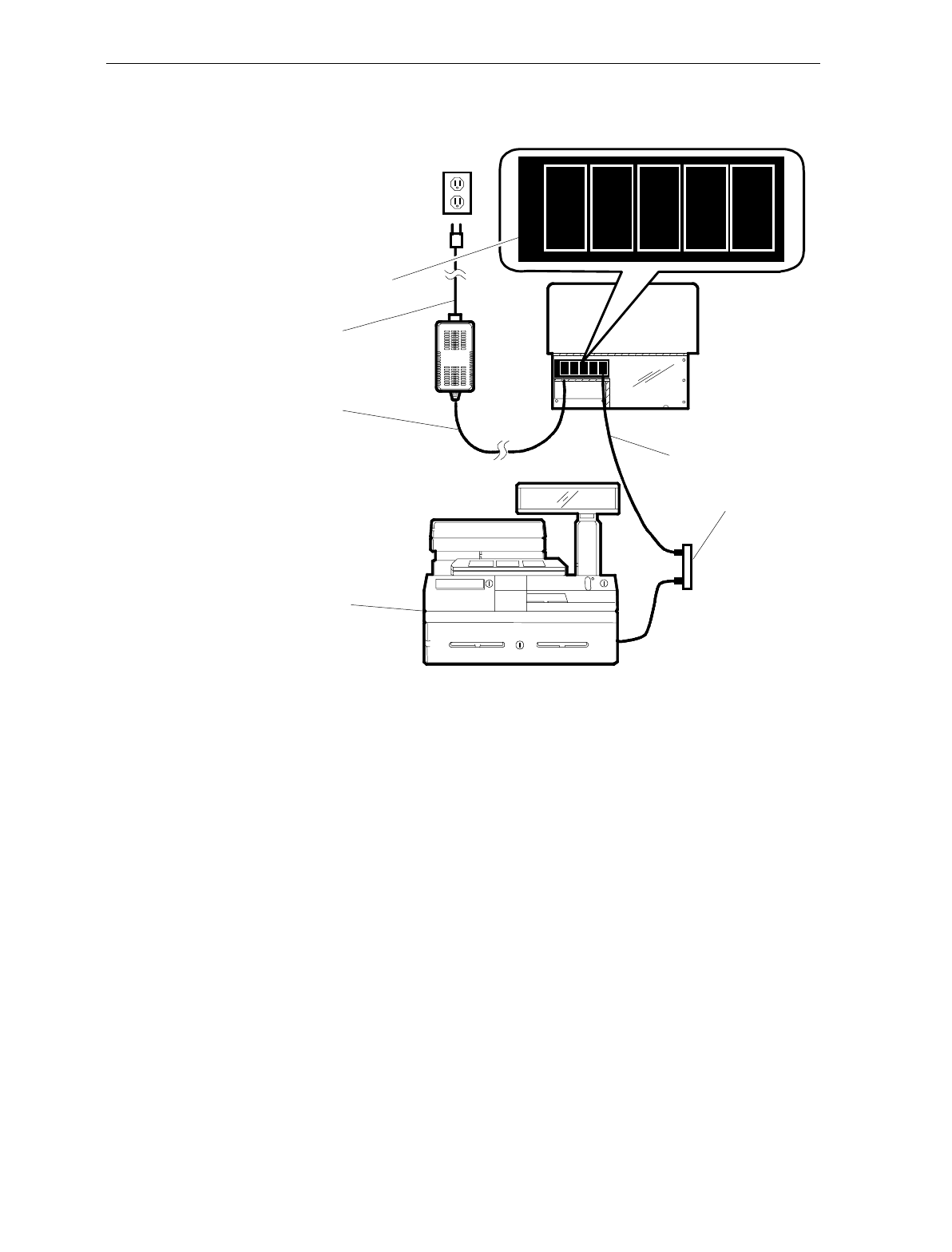
4-6 Chapter 4: Installation
Datachecker or RS-232 Cable Set-Up
DC
POWER
REMOTE
DISPLAY
RS-232
TERMINAL
DISPLAY
DATACHKR
Interface Ports Label
Power Cord
Power Cord
Interface Cable
Terminal Junction Box
Host Terminal
11628
Note: Use the Terminal Junction Box as needed to provide additional
ports. Contact your terminal vendor for ordering information.
10. If the checkstand counter has adjustable posts to support the NCR
7870, set to the following:
• Scanner Only Models: 0.95 cm (0.375 in.) deep
• Scanner/Scale Models: 1.27 cm (0.50 in.)
If fixed flanges are used, ensure they are at the appropriate height.
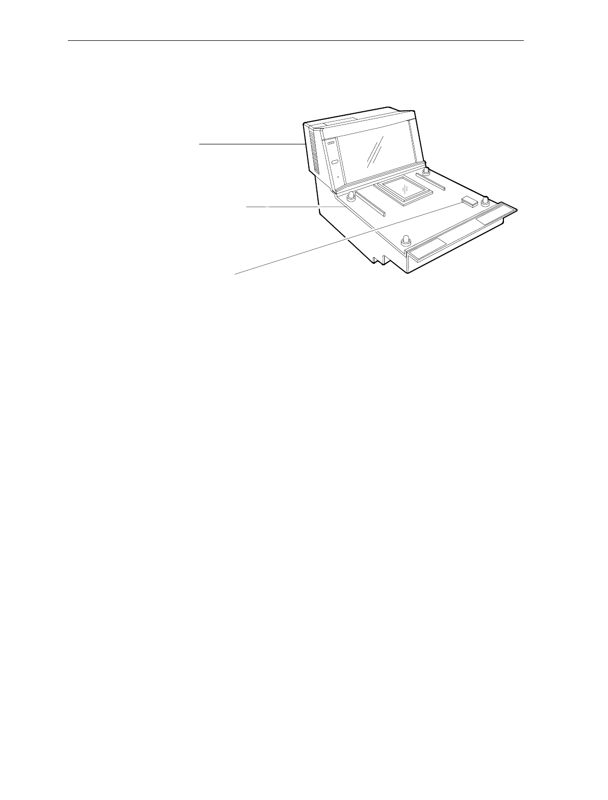
Chapter 4: Installation 4-7
11. Locate small plastic Cover inset in Subplate Assembly. Carefully
release Cover.
11189
Subplate Assembly
Cover/Lift Strap
Tower
12. Use Cover/Lift Strap to lift the unit.
13. Position unit over checkstand cutout.
14. Lower unit into cutout.
For proper operation, the NCR 7870 must be level. It should have
support within two inches of each corner to prevent rocking. Also,
the leading edge of the Top Plate must be flush or up to 0.15 cm
(0.06 in.) below the counter top. The trailing edge of the Top Plate
must be flush with the checkstand.
Note: The four adjustable support posts on the Scale Hinge
Assembly are set at the factory. Do NOT attempt to adjust the Top
Plate by using these posts.
15. Replace Cover.
16. Place Top Plate on the four supports (plastic caps for scanners,
rubber bumpers for scanner/scales).
17. Turn ON the unit using the circuit breaker switch.
End of Procedure

4-8 Chapter 4: Installation
Determining if the Unit is Operational
When power is applied to the NCR 7870 Scanner/Scale, it
automatically performs Level 0 Diagnostics to check various
components.
NCR 7870-1000 and 3000 Scanners
After passing Level 0 diagnostics the Status indicator flashes green, a
tone sounds, then the Status indicator turns red. The NCR 7870 is now
operational.
NCR 7875-2000, 4000, and 4500 Scanner/Scales
After passing Level 0 diagnostics the NCR 7870 runs scale diagnostics.
During this time, all segments on the integrated or remote display are
turned ON so the operator can verify the display works correctly.
Then the display reads Ready 0.000 kg (Ready 0.00 lb). The Status
Indicator flashes red for five seconds, then the Status indicator flashes
green momentarily, a tone sounds, and the Status indictor turns red.
The NCR 7870 is now operational.
If the NCR 7870 Does Not Pass Level O Diagnostics
If an error occurs during Level 0 diagnostics, the integrated or remote
display (if the unit has one) displays an error code, and if enabled, the
NCR 7870 emits an audible description of the error and what action to
take. There may be some simple steps you can take to correct the
problem. See Chapter 8: Troubleshooting. If you cannot correct the
problem, contact NCR for warranty information.

Chapter 4: Installation 4-9
Checkout Reading Operation
To check the tag reading operation of the NCR 7870, attempt to read a
good tag on an item. The Status indicator turns red when the NCR
7870 is ready to scan a label. A good read is indicated when the Status
indicator turns green and a tone sounds (if enabled).
Programming Your NCR 7870 comes from the factory with the programming
parameters set to default values. The Communications Protocol is set
to the specifications on your order. However, you may want to make
some parameter changes for your particular installation. See Chapter
7: Programming.

4-10 Chapter 4: Installation
Determining Communications Protocol
Use the following procedure to determine the communications
protocol programmed in your NCR 7870.
1. Apply power to the NCR 7870.
2. Scan the Diagnostic Mode tag -- must be first tag scanned after
applying power.
3. Scan the Hex 3 tag. The good read tone for this tag sounds (three
beeps).
If the NCR 7870 has the Voice feature enabled, the communications
protocol is given audibly. If the Voice feature is not enabled, the Status
Indicator flashes green and the tone beeps, identifying the
communication protocol.
Tone Communications Protocol Hex Code
1 short, high-
pitched beep OCIA NCR Short 100
1 beep OCIA NCR Long 101
2 beeps IBM 468x/9x Port 4A (Slot Scanner) 102
3 beeps IBM 468x/9x Port 4B (HHBRC) 103
4 beeps IBM 468x/9x Port 4B (HHBCR) 104
6 beeps RS-232 105
7 beeps OCIA Single Cable 106
8 beeps OCIA NCR Dual Cable 107
11 beeps Casio 4-Bit, Parallel, Dual Cable 10A
12 beeps IBM 1520 (BRC) 10B
13 beeps TEC 4-Bit, Parallel, Dual Cable 10C
4. Remove power from 7870.

Chapter 4: Installation 4-11
Scale Address for IBM
Most IBM systems have software called Integrated Scanner/Scale that
permits a single-cable installation. You can check the terminal
configuration at the controller to be sure this IBM option is activated.
Once chosen, the scale address is 6E (default setting), and no other
action is required other than plugging the NCR 7870 interface cable
into port 17 (468x). This is the preferred and most common
configuration. For the 4682/469x series IBM terminals, the NCR 7870
interface cable plugs into port 9B. This series has no port 17.
Some older 468x systems require a dual-cable system, where one cable
connects to the scanner and the other connects to the scale. The scale
cable usually plugs into port 21 of a "B" or "C" feature card. It is
possible to preserve the existing terminal configuration and still use the
single-cable feature of the NCR 7870. If there are no other ports used
on the "B" or "C" feature card, you can remove the feature card from
the terminal even though it is configured to be installed.
• If the card was in slot 2A, program the NCR 7870 scale address to
6A and plug the NCR 7870 Interface Cable into port 17.
• If the card was in slot 2B, program the NCR 7870 scale address to
6B and plug the NCR 7870 Interface Cable into port 17.
• If other ports beside port 21 are used on the "B" or "C" card and the
other card slot is empty (2A or 2B), you can still use this procedure
but the terminal configuration must be changed to define that there
is a card in the empty slot and that its port 21 is connected to a
scale. Program the scale to the empty slot address (2A = 6A,
2B = 6B). The existing card port 21 must be configured as not used
and must not be removed from the terminal.
• If both card slots are used on the terminal, the terminal software
must be a version that can be configured to support an integrated
scanner/scale. This may require upgrading the software.

4-12 Chapter 4: Installation

Chapter 5: Calibration
General
This chapter describes when and how to calibrate the NCR 7870
scanner/scale models and how to verify that the calibration is correct.
Please note, this chapter pertains to the NCR 7870-2000 and 4500
ONLY. The NCR 7870-4000 does not require calibration. In the event
calibration is needed, contact the NCR Service Center. The 7870-4000
has NO user serviceable scale parts or calibration procedure.
During factory testing, the scale is calibrated one or more times to test
the scale calibrating function. This calibration test is not sufficient to
make the scale ready for weighing in commerce. To be in compliance
with governmental Weights and Measures regulations, you must be
certified to perform the scale calibration procedure and place the scale
into service for trade.
You MUST calibrate the scale when any of the following occurs.
• Initial installation of an NCR 7870 Scanner/Scale
• When scale cannot be zeroed even after a power down/up
sequence
• When the diagnostics indicate a calibration error that persists
after a power down/up sequence
• When the Load Cell or Scale Board have been replaced
Note: Your scanner/scale may or may not have an Integrated Display
or an NCR 7825 Remote Display when connected to some host
terminals. If this is the case, a Field Service Calibration Display (NCR
part number 250-0029750) is required unless your NCR 7870 has the
optional Voice Messaging feature enabled. Calibration information is
NOT sent to the host terminal.

5-2 Chapter 5: Calibration
The calibration procedure sets the Load Cell and the electronics to
interpret the weight of an item accurately. You can calibrate the scale
after power has been supplied for 30 minutes if the ambient air
conditions have been 20° C (68° F) for at least 24 hours. If the ambient
air conditions have not been met, then the scale must be on for at least
6 hours before you can calibrate it. One or more certified weight sets
are required to calibrate and certify the scale.
• Whole Pound Weight Set: NCR Part Number 998-0633009
• Fractional Pound Weight Set: NCR Part Number 998-0633012
• Kilogram Weight Set: Obtain locally
The EEPROM on the Scale Board maintains an audit trail of scale
calibration and weigh parameter setting. The audit trail consists of two
event counters. You can display the audit trail count by pressing and
holding the Scale Zero button on the Operator Display Panel. The
display alternates between Cal xxx and PAr xxx. The Cal value is the
number of times the scale has been calibrated. The PAr value is
associated with the weigh parameter setting and should never change.
Note: The audit trail can be displayed only on units with the Integrated
Display or with the NCR 7825 Remote Display.

Chapter 5: Calibration 5-3
Calibration Procedure
Section 1: Exercising the Scale
Tools
One of the following:
Whole Pound Weight Set (P/N 998-0633009)
Fractional Pound Weight Set (P/N 998-0633012)
Kilogram Weight Set Obtain locally
Instructions
You must exercise the scale before performing a calibration.
1. Select appropriate Weight Feature for your Scanner/Scale.
Weight Feature Total Weight on Top Plate
9.995 kg 0.0 kg 2.5 kg 5.0 kg 10.0 kg 5.0 kg 2.5 kg 0.0 kg
13.995 kg 0.0 kg 2.5 kg 5.0 kg 15.0 kg 5.0 kg 2.5 kg 0.0 kg
30.0 lb. 0.0 lb. 5.0 lb. 15.0 lb. 30.0 lb. 15.0 lb. 5.0 lb. 0.0 lb.
2. Add and remove weights to your scale in order given in chart.
This is a building procedure in which you start with no weight (0)
and sequentially add and remove weight to obtain the values
shown in the chart.
3. Go through procedure four times.
4. Go to Section 2: Accessing the Calibration Switch.
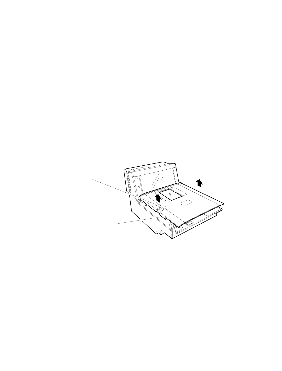
5-4 Chapter 5: Calibration
Section 2: Accessing the Calibration Switch
Tools
Screwdriver, flat blade
Needle-nosed pliers (optional)
The Scale Calibration Switch is located on the Scale Board. For security
this switch is not readily accessible and may be secured with a
lead/wire seal or seal sticker.
Instructions
1. Remove power from unit.
2. Remove Top Plate:
a) Press lift tab in.
b) Grasp lift tab and lift Top Plate off unit.
11041
Lift Tab
Top Plate Assembly
3. Remove Subplate Assembly.
a) Pop cover off of Lift Strap Assembly.
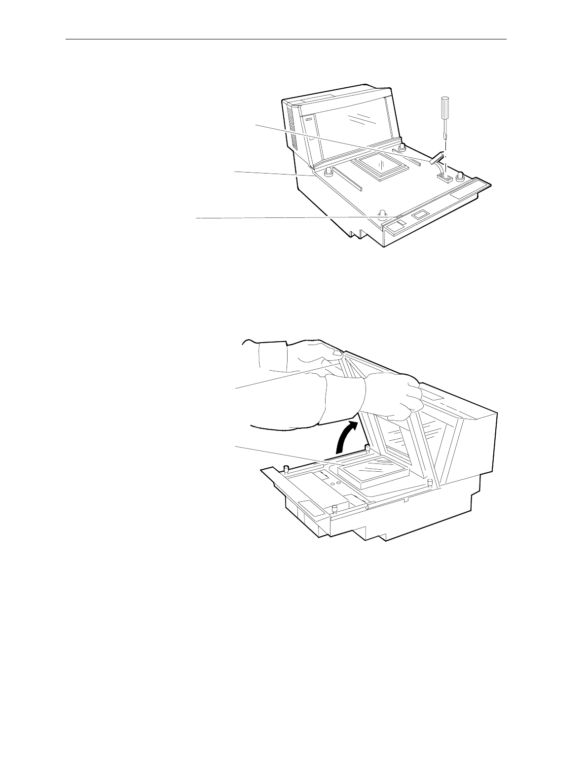
Chapter 5: Calibration 5-5
b) Remove screw securing Lift Strap to unit.
11053
Cover/Lift Strap Assembly
Subplate Assembly
Tab Slot
c) Insert screwdriver blade into Tab Slot. Twist to free tab.
d) Lift the front of Subplate Assembly into a nearly vertical
position. Pull the back edge from under the Tower Cabinet
and remove the Subplate Assembly.
Subplate Assembly
Horizontal Window
11039
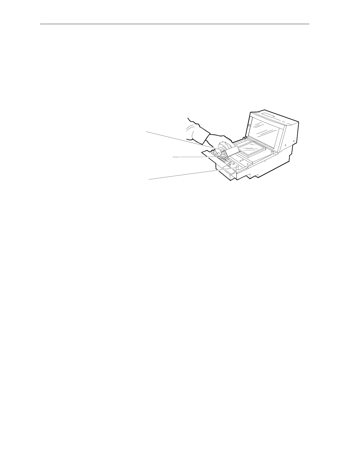
5-6 Chapter 5: Calibration
4. Remove the Scale Board Shield.
a) Break seal wire and seal sticker if present.
b) Remove thumbscrew. Use needle-nosed pliers to loosen if
thumbscrew is tight.
c) Remove Shield.
Scale Hinge Assembly
Calibration Switch (under shield)
Scale Board Shield
11040
5. Set Top Plate on rubber bumpers of Scale Hinge Assembly. Make
sure bumpers fit into corresponding sockets on bottom of Top
Plate.
6. Apply power to 7870.
7. Does the unit have any of the following: an Integrated Display, a
7825 Remote Display, or the Voice Messaging Feature (must be
enabled)?
NO → Go to Section 3 - Connecting the Field Service Calibration
Display
YES → Go to Section 4 – Performing the Calibration
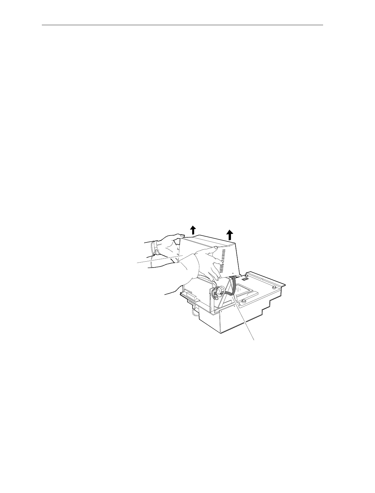
Chapter 5: Calibration 5-7
Section 3: Connecting the Field Service Calibration Display
Tools
Field Service Calibration Display (P/N 250-0029750)
Philips screwdriver
The Field Service Calibration Display provides calibration information
when no other display is available. To connect the Field Service
Calibration Display, perform the following.
Instructions
1. Remove Tower Cabinet.
Note: On some models, taking the Top Plate off first may make Tower
Cabinet removal easier.
a) Remove four (4) screws from Tower Cabinet base.
b) Carefully lift Tower Cabinet straight off unit. Check Indicator
Panel harness to ensure it is still connected.
Tower Cabinet
Indicator Panel Harness
16828
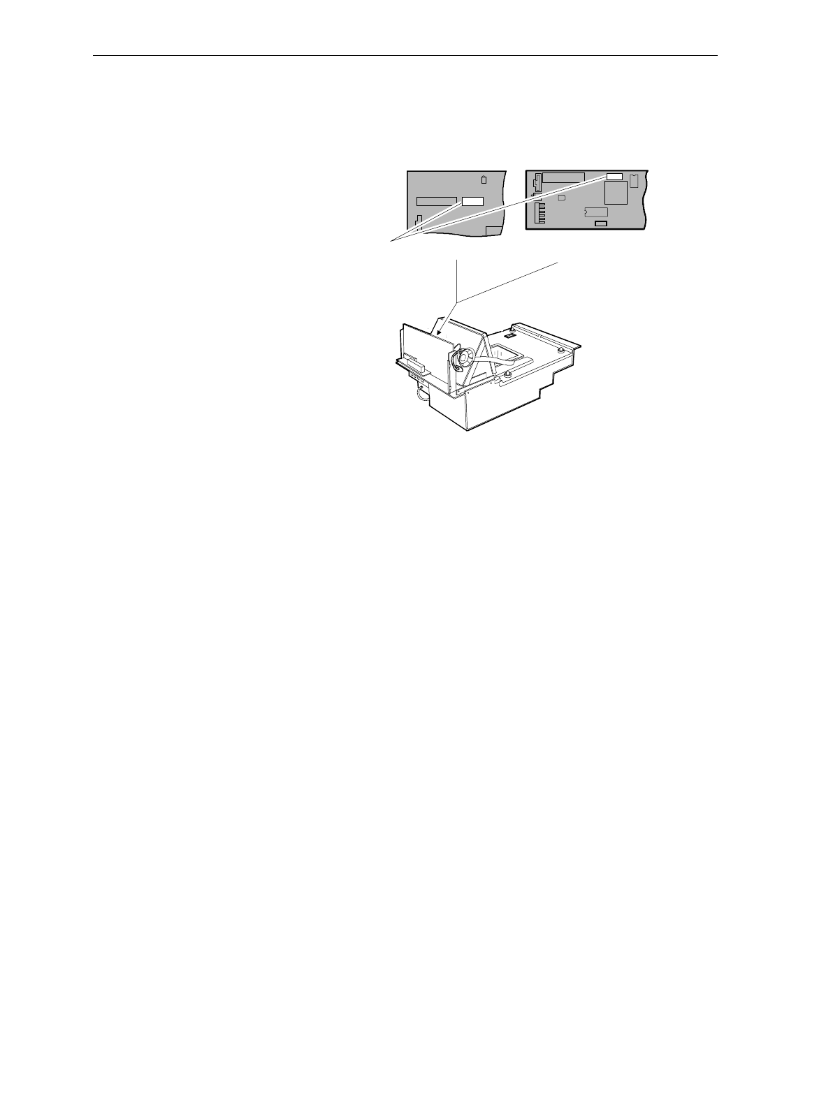
5-8 Chapter 5: Calibration
c) Connect the Field Service Calibration Display to J-4 on the LC-
Digital Board (J-5 on the old Digital Board).
LC Digital Board
J3
J1
Old Style Digital Board
Integrated Display Connector
J3
J2
DS1
J5
J4
11279
d) Apply power to NCR 7870.
e) Go to Section 4: Performing the Calibration

Chapter 5: Calibration 5-9
Section 4: Performing the Calibration
The scale firmware controls calibration. It waits for you to respond to
the prompt before going to the next step. When you have placed the
weight on the Top Plate and pressed the Scale Zero button, the
firmware sounds a single tone and changes the display to the next
prompt. If voice is enabled, the scale tells you which weight to put on
next. You can end the procedure before you have completed the
calibration function by turning the unit off. However, if you do this,
you must still calibrate the scale before placing it into service.
Note: the pound and kilogram weights used for calibration are not
equivalent values. They are the actual weights the firmware needs to
perform the calibration.
Instructions
For the purpose of this procedure, a scale set-up to weigh pounds is
used. Kilogram scales follow the same instructions but use the
appropriate weights (shown in parentheses).
1. Press the Reset/Scale Zero button to display the Cal and PAr
values. Record these values.
2. Remove Top Plate and press the Calibration Switch on the Scale
Board.
3. Immediately reinstall Top Plate. Ensure that rubber bumpers of
Scale Hinge Assembly are properly seated in sockets of Top Plate.
4. Display should show Ready C 0.00 lb (0.000 kg).
5. The calibration process consists of sequentially adding and then
removing a series of weights. This sequence is shown in the
following table.

5-10 Chapter 5: Calibration
Display Add Weight Remove Weight
Ready C-5.00 lb (2.500 kg) 5.00 lb. (2.500 kg)
Ready C-15.00 lb (5.000 kg) 10.00 lb. (2.500 kg)
Ready C-30.00 lb (10.000 kg) 15.00 lb. (5.00 kg)
Ready C-0.00 lb (0.000 kg) 30.00 lb. (10.000 kg)
Ready 0.00 lb (0.000 kg)
Note: Use the same kilogram weights for both 9.995 kg and 13.995 kg
scale units.
6. Press Reset/Scale Zero button. Display will indicate Ready C 5.00
lb (or 2.500 kg).
7. Place a 5.00 lb (or 2.500 kg) weight in center of Top Plate.
8. Press Reset/Scale Zero button. Display will indicate Ready C 15.00
lb (5.000 kg).
9. Add a 10.00 lb (2.500 kg) weight in center of Top Plate. Total
weight on scale should be 15 lbs. (5.00 kg).
10. Press Reset/Scale Zero button. Display will indicate Ready C 30.00
lb (10.000 kg).
11. Add a 15.00 lb (5.000 kg) weight in center of Top Plate. Total
weight on scale should be 30.00 lbs (10.000 kg).
12. Press Reset/Scale Zero button. Display will indicate Ready C 0.00
lb (0.000 kg).
13. Remove all weights.
14. Press Reset/Scale Zero button. Verify display indicates Scale
Ready 0.00 lb (0.000 kg).
15. Press and holdReset/ Scale Zero button. Record Cal and Par
values.
16. The Cal value should be incremented by one, indicating that a
calibration has been performed. The PAr value should remain
unchanged.

Chapter 5: Calibration 5-11
Verifying Calibration
This section describes how to verify that the 7870 has been properly
calibrated.
No error codes should appear during calibration. The codes are shown
in the table below. If a code is displayed, the calibration is invalid and
a corrective action must be undertaken before attempting recalibration.
Error
Code Problem Suspect Component
1 - - - - Calibration error
A/D output below 000h at digital to
analog converter
Scale Board
Load Cell
2 - - - - Calibration error
A/D output below 280h at digital to
analog converter
Scale Board
Load Cell
3 - - - - Calibration error
Analog to digital converter output
too high at 15 kg (30.0 lb.)
Scale Board
Load Cell
4 - - - - Vibration to scale during calibration Motors in checkstand
9 - - - - Interference detected during
calibration Top Plate is touching
checkstand, scale was
jarred, or overload screw
is misadjusted.
If no error codes occur during calibration, four test procedures must be
performed to verify calibration. These procedures are, in order,
• Increasing Load Test ,
• Over-Capacity Test,
• Decreasing Load Test, and
• Shift Test.

5-12 Chapter 5: Calibration
Procedure 1: Increasing Load Test
This test checks the scale’s accuracy by incrementally adding weight to
the center of the Top Plate. Use weights that correspond to the NCR
7870 weight feature. If this test fails, recalibrate scale.
Instructions
1. Select the appropriate weight feature from the table below.
Step Weight Feature Add
Weight Remove
Weight Display
19.995 kg
13.995 kg
30.0 lb.
0.1 kg
0.1 kg
0.2 lb.
0.1 ± 0.00 kg
0.1 ± 0.00 kg
0.2 ± 0.00 lb.
29.995 kg
13.995 kg
30.0 lb.
2.5 kg
2.5 kg
5.0 lb.
0.01 kg
0.01 kg
0.2 lb.
2.5 ± 0.00 kg
2.5 ± 0.00 kg
5.0 ± 0.00 lb.
39.995 kg
13.995 kg
30.0 lb.
2.5 kg
4.5 kg
5.0 lb.
5.0 ± 0.005 kg
7.0 ± 0.005 kg
10.0 ± 0.01 lb.
49.995 kg
13.995 kg
30.0 lb.
2.5 kg
3.0 kg
10.0 lb.
7.5 ± 0.005 kg
10.0 ± 0.005 kg
20.0 ± 0.01 lb.
59.995 kg
13.995 kg
30.0 lb.
2.495 kg
3.995 kg
10.0 lb.
9.995 ± 0.005 kg
13.995 ± 0.005 kg
30.0 ± 0.01 lb.
2. Follow steps shown in table for the weight feature of your scale.
3. Check readout after completing each step and verify the measured
value falls within the acceptable limits.
4. If a measured value does not fall within limits, recalibrate scale. If
all measured values are acceptable, the scale has passed the
Increasing Load Test. Go to Procedure 2: Over-Capacity Test.
Note: Do NOT remove any weights from the Top Plate.

Chapter 5: Calibration 5-13
Procedure 2: Over-Capacity Test
This test checks for the proper indication from the scale when too much
weight is placed on the Top Plate. An over-capacity is indicated by
dashes appearing on the display. If a failure occurs during this test, the
scale must be recalibrated.
Note: This test must immediately follow the Increasing Load Test. Do
not remove any of the weights prior to running this test.
Instructions
1. Use the following chart to select the correct weight.
2. Follow steps on chart for adding and removing weights. Weight
must be placed in center of Top Plate.
Step Weight Feature Add
Weight Remove
Weight Display
1 9.995 kg
13.995 kg
30.0 lb.
0.04 kg
0.04 kg
0.08 lb.
- -.- -
- -.- -
- -.- -
2 9.995 kg
13.995 kg
30.0 lb.
0.04 kg
0.04 kg
0.08 lb.
9.995 ± 0.005 kg
13.995 ± 0.005 kg
30.0 ± 0.01 lb.
3. If a series of dashes are not shown, then the scale has failed and
must be recalibrated.
4. The scale passes the test if a series of dashes is displayed and all
measured values fall within the acceptable limits Continue to
Procedure 3: Decreasing Load Test

5-14 Chapter 5: Calibration
Procedure 3: Decreasing Load Test
This test checks the scale’s accuracy when incrementally removing
weight from the Top Plate. Use weights that correspond to the NCR
7870 weight feature. If a failure occurs during this test, you must
calibrate the scale again.
Note: This test must immediately follow the Over-Capacity Test; do
not remove any of the weights prior to running this test.
Instructions
1. Select appropriate Weight Feature for your Scanner/Scale.
2. Follow the four steps shown in chart.
Step Weight Feature Add
Weight Remove Weight Display
1 9.995 kg
13.995 kg
30.0 lb.
2.495 kg
3.995 kg
10.0 lb.
7.5 ± 0.005 kg
10.0 ± 0.005 kg
20.0 ± 0.01 lb.
2 9.995 kg
13.995 kg
30.0 lb.
5.0 kg
7.5 kg
15.0 lb.
2.5 ± 0.00 kg
2.5 ± 0.00 kg
5.0 ± 0.00 lb.
3 9.995 kg
13.995 kg
30.0 lb.
0.1 kg
0.1 kg
0.2 lb.
2.5 kg
2.5 kg
5.0 lb.
0.1 ± 0.00 kg
0.1 ± 0.00 kg
0.2 ± 0.00 lb.
4 9.995 kg
13.995 kg
30.0 lb.
0.1 kg
0.1 kg
0.2 lb.
0.0 ± 0.00 kg
0.0 ± 0.00 kg
0.0 ± 0.00 lb.
4. If display does not read within limits shown, the scale has failed
and must be recalibrated.
5. If the displayed measurements fall with the acceptable limits, the
scale has passed. Go to Procedure 4: Shift Test
Chapter 5: Calibration 5-15
Procedure 4: Shift Test
This test consists of measuring a weight in the center and four
positions on the Top Plate.
2
34
5
1
11033
Instructions
1. Place a 15.00 lb (or 5.000 kg) weight in Position 1 and record
measured weight.
2. Move sequentially to Positions 2, 3, 4, and 5. Record measured
weight for each position.
3. Move weight back to Position 1 and record measured value.
4. All measurements should fall within
• 15.00 lb ± 0.01 lb (for 30.00 lb scales)
• 5.000 kg ± 0.005 kg (for 9.995 and 13.995 kg scales)
5. If any measured weight does not fall within acceptable range, scale
has failed test and must be recalibrated.
6. If the scale passes all four tests, the calibration is successful.
7. Now the calibration seals, if required by local laws, can be placed
and the Calibration Switch secured before reassembling the unit.

5-16 Chapter 5: Calibration
Securing the Calibration Switch
Most countries require that the Calibration Switch and Scale Board be
secured before a unit can be put into operation.
Some states and jurisdictions permit the use of the Audit Trail in place
of the physical seals. Check with your local inspector or governmental
agency about using the Audit Trail.
This procedure begins with the unit already disassembled with Tower
Cabinet in place and access to the Calibration Switch.
Prior Steps
Calibration Switch accessible. See Section 2: Accessing the Calibration
Switch.
Tools
Needle-nosed Pliers
Lead/Wire Seal P/N: 603-8001097
Lead/Wire Seal Press P/N: 603-9000157
Film/Paper Seal Obtain locally – must meet local government
requirements
Instructions
1. Install Scale Board Shield.
a) Position Shield so it encloses edge of Load Cell Shield, if
present.
b) Insert tabs of Shield into slots.
c) Place Shield into position and attach thumbscrew. Tighten
with pliers if necessary.
2. Attach seal and/or wire tag to control access to Calibration Switch.

Chapter 5: Calibration 5-17
Note: When you perform a scale certification, someone must attach a
seal to the Calibration Switch Security Cover. Depending on your local
laws, Weights and Measures officials may be required to attach the
seal.
3. Install Subplate Assembly.
a) Position Subplate with front end up to near vertical.
b) Push back edge of Subplate under edge of Tower Cabinet.
c) Gently press Subplate into position on unit chassis. Ensure
Retaining Tab snaps into slot.
d) Install Cover/Lift Strap in access hole. Tighten screw and snap
cover into place.
4. Set Top Plate on rubber bumpers of Scale Hinge Assembly. Verify
bumpers are seated in sockets.
5. Apply power to 7870.
6. Verify that display indicates Scale Ready 0.00 lb (0.000 kg).
7. Record the Cal and PAr values, shown on the display, on the
Placed Into Service form if required by your local Weights and
Measures regulations.

5-18 Chapter 5: Calibration
Chapter 6: Operation
This chapter describes how to operate the NCR 7870. Following is a
diagram of the NCR 7870.
Integrated Scale Display
Vertical Scan Window
Horizontal Scan Window
Top Plate
Operator Display Panel
RESET
SCALE ZERO
Scanner
Operator Display Panel
Red Status
Indicator
Green Status
Indicator
Reset/Zero
Indicator
Reset/Scale
Zero Button
Motion Detector
Red Status
Indicator
Green Status
Indicator
Reset Indicator
Reset Button
Motion Detector
Scanner/Scale
Operator Display Panel
R0125

6-2 Chapter 6: Operation
About Using the Operator Controls
Scan Windows The NCR 7870 contains a vertical and horizontal scan window. The
vertical scan window is mounted in a Tower Cabinet that rises above
the checkstand surface. The horizontal scan window is flush-mounted
in the Top Plate.
Status Indicators
Status Indicator Function Occurs
Red
(Steady) Indicates unit is in standby
mode to read next label. Between scanning.
Green Flashes once to indicate a
successful bar code read. After scanning.
Yellow Indicates scale has been
reset/zeroed.
Signals a scale error code may
be on display.
When Scale Zero
button is pressed.
Primarily during
Power Up.
Red
(Slow
Flash)
Indicates unit is off-line. Host
terminal may be off or
interface cable is not
connected.
When IBM 468x
communication is
used.
Red-Green
Flashing Indicates Failure Mode. A
scanner error code will be
repeated.
During Power Up.
Red-Red-
Red Three red flashes indicate an
item is not on record in price
lookup file.
After scanning an
item.
Red-Green
Alternate Sleep Mode During operator
inactivity.

Chapter 6: Operation 6-3
Motion Detector
The Motion Detector is used to detect operator inactivity and power
down critical components of the NCR 7870 to reduce wear and extend
product operational life
Reset / Scale Zero Button
This button is used to
• re-zero the scale if not performed automatically,
• set a tare weight, and
• awaken the unit from Sleep Mode.
Audible Tone A tone can be programmed to sound to indicate a successful bar code
read. This may be easier for the checker than watching the Status
Indicators. The tone’s frequency, volume, and duration can also be set
via programming. The NCR 7870 comes from the factory with the tone
enabled.
See Chapter 7: Programming for more information on the Good Read
programming parameter.
Voice Messages
If equipped, this feature provides a voice message when
• the scanner/scale goes on-line or off-line,
• the communication protocol is checked,
• item tags are checked using PACESETTER Plus,
• certain error conditions exist,
• there is interference with the scale, and
• when the scanner windows may be dirty.
6-4 Chapter 6: Operation
About Using the Scanner
Proper Label Orientation
Because the NCR 7870 uses bi-optic scanning, labels can be read from
many angles. Labels can be read from the leading, trailing, bottom,
and opposite sides of a package. Bar code labels can be scanned from
left-to-right or right-to-left. A good rule of thumb is – if you can’t see
the label, the NCR 7870 can read it.
Bar Code Label
R0126
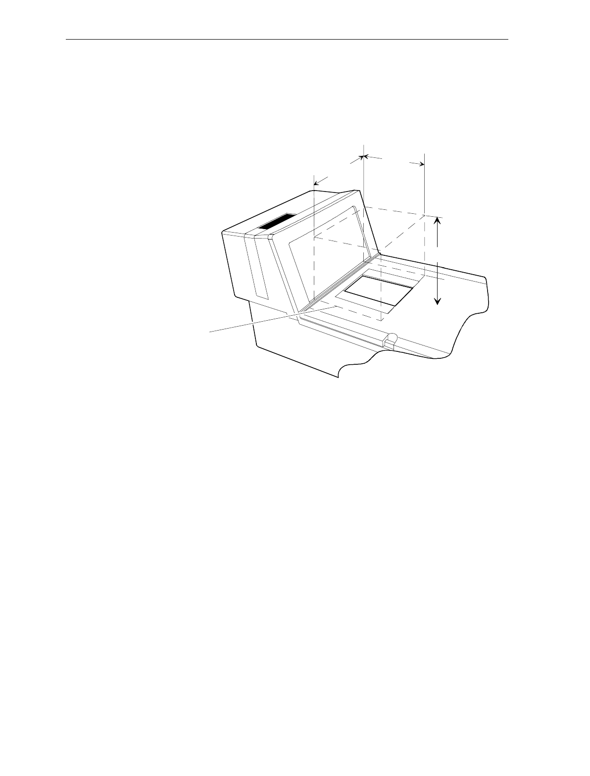
Chapter 6: Operation 6-5
Active Scan Zone
The active scan window is shown in the following diagram. The 7870
can read labels presented within the cube.
Scan Zone
5.0
(12.7 cm)
6.0 in.
(15.2 cm)
5.8 in.
(14.7 cm)
R0127
Multiple Reads Only one good read is reported if a label is placed within the scan zone
and left there. Scanner firmware prevents a second read of the same
label if it occurs within a preset time of a good read.
The preset time is tag-programmable from 250 to 1500 milliseconds in
50 millisecond increments. The factory default is 900 milliseconds. To
scan a label a second time, remove the item from the scan zone and
then scan it again after the preset time has elapsed.
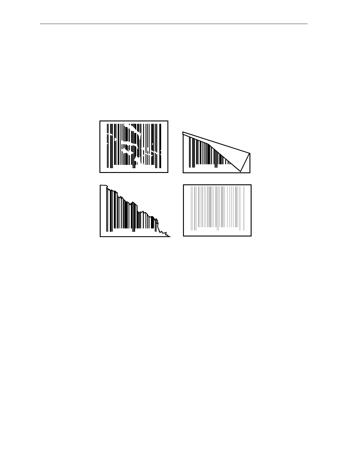
6-6 Chapter 6: Operation
Bar Code Quality
Many labels in a typical retail environment are unreadable. The
illustration shows some of the common problems. Vendors and
printers regularly supply products to the market with bar codes that
are overprinted, underprinted, or truncated. Some labels have missing
margins. Others may be printed around the corners of packages, or on
media not likely to remain flat when picked up.
0 1 2 3 4 6 7 85 9
06
0 1 2 3 4 6 7 85 9
06
0 1 2 3 4 6 7 85 9
06
0 1 2 3 4 6 7 85 9
06
R0026
The readability of a label depends on variables such as size, placement,
color, paper type, ink viscosity, and package coatings. The middle of a
printing run can yield erroneous labels due to the many variants
involved. In particular, poor color contrast and marginal print quality
can make a label hard to read.
A label should be considered readable if it meets or exceeds the
requirements set forth in the UPC Symbol Specification published by
the UPC Council, Inc. (March 1982), and the General Specification for
Article Symbol Marking, Copyright EAN-1977.

Chapter 6: Operation 6-7
Operating Instructions
Power Up The 7870 has no ON/OFF switch. The checkstand should be equipped
with a circuit breaker switch during site preparation. The switch
should be easily accessible and near the operator.
Power up the NCR 7870 on by turning the circuit breaker switch to
ON. The NCR 7870 performs diagnostic checks during the power up
procedure. If a scale error occurs, the yellow Status Indicator will light
and an error code will appear on the NCR 7825 Remote Display or
Integrated Display. If a scanner error is detected, and error tone will
sound and the red and green Status Indicator lights will flash a code.
In the event of a problem in the power up process, call a supervisor,
service company, or the NCR Customer Service Center for assistance.
Scanner Only Models
For the 1000 and 3000 models, if no error occur during power up the
unit will enter Startup Mode. The red Status Indicator will flash, the
green Status Indicator will flash, and a tone will sound. The red Status
Indicator will then light. The unit is ready for use.
Scanner/Scale Models
For the 2000, 4000, and 4500 models, if no errors occur during power
up the unit will enter Startup Mode. The red Status Indicator will flash
and all segments on the display (remote or integrated) will be turned
on for five seconds. The green Status Indicator light will flash , a tone
will sound, and the display will show SCALE READY 0.000 kg or
SCALE READY 0.00 lb. The red Status Indicator will light. The unit is
ready for use.
The Scanner/Scale models should warm up for five minutes before
being put into use.

6-8 Chapter 6: Operation
Scanning Procedure
To use the NCR 7870, the item must pass through the active scan
region. Item orientation, motion, and sequential handling are required
for proper label reading.
Instructions
1. Verify scanner is operable. The red Status Indicator must be lit.
2. Locate label on item.
3. Orient item so label faces away from you.
4. Pass item across the lower scan window.
5. If a good read occurs, the green Status Indicator will flash. A tone
will sound if the Good Tone parameter has been enabled. The red
Status Indicator will light indicating the unit is ready to read
another bar code.
6. If a good read does not occur, scan the item again.
7. If a good read still does not occur, manually enter information for
the item. Continue to scan.
Not-On-File Error
The Not-On-File feature is available on the NCR 7870 only if the host
terminal has this capability. If a label is not in the price lookup file, a
special tone sounds three times a second and the red Status Indicator
flashes repeatedly. The volume of the Not-On-File tone is
programmable.
The unit becomes disabled from reading additional labels until the
error is cleared. To clear, press the host terminal’s CLEAR key and
manually enter the information.

Chapter 6: Operation 6-9
Weighing Procedure
The NCR 7870 has a settling time of 0.9 seconds for items five pounds
or less and 2 seconds for items over five pounds. The scale will not
weigh items exceeding its weight class – 9.995 kg, 13.995 kg, and 30 lbs.
The scale can be operated in Mode 1 or Mode 2, depending on your
terminal and the type of NCR 7870. In Mode 1, the weight is
displayed. In Mode 2, the weight and price are displayed.
Instructions
1. Verify display reads SCALE READY 0.000kg or SCALE READY
0.00lb and red Status Indicator is lit.
2. If display or Status Indicator is not on, press Reset/Scale Zero
button. If this does not work, power unit off and on.
3. Place an item on center of Top Plate. Ensure item does not
overhang. Item must rest completely on the Top Plate.
4. Item weight is displayed. Press Weight Request key on host
terminal.
5. If a bad weigh occurs, re-weigh item.
6. If red Status Indicator is still lit, remove the item from Top Plate.
Remove Top Plate and check for obstructing material or debris.
7. Replace Top Plate. Press Reset/Scale Zero button.
8. Wait for SCALE READY 0.000kg or SCALE READY 0.00lb. Weigh
item again.
9. If no weight is displayed and/or the red Status Indicator is still lit,
contact your supervisor, service company, or the NCR Customer
Service Center.

6-10 Chapter 6: Operation
Changing the Good Read Tone
The volume of the Good Read Tone can be changed while in normal
operating mode. This is the only characteristic of the tone that can be
changed without being in Programming Mode.
Instructions
1. Scan the Volume Adjustment tag and listen to the tone.
2. If the tone is not loud enough, scan the tag again. Repeat if
necessary.
3. If the tone is too loud, scan the tag repeatedly until the volume
resets to the lowest level. Now scan to the desired level.
4. When the volume is acceptable, scan the Save and Reset tag to end.
If the Save and Reset tag is not scanned, the unit will not operate.

Chapter 6: Operation 6-11
Routine Maintenance
Routine maintenance is needed at least once a day to keep the NCR
7870 in good operating condition. These parts of the 7870 can be
cleaned with a soft cloth, lukewarm water, and mild soap:
• Scanner body
• Top Plate and Scan Window
• Exterior surface of Subplate Assembly
• Optics Assembly Window
• Horizontal Scan Window
• Tower Cabinet
If a scan window becomes excessively scratched, replace it. If the unit
becomes wet due to a spill, clean and dry as soon as possible.
Instructions
Clean the Top Plate and Scan Windows with a soft cloth and a non-
abrasive liquid window cleanser as follows.
1. Power unit down.
2. Remove Top Plate. Clean Top Plate and the inset Scan Window.
3. Clean window inset in Optics Assembly.
Note: Do not spray the cleanser directly on plastic cover or scale
mechanism holes.
4. Clean vertical Scan Window in Tower Cabinet.
5. Wipe surfaces with a soft, dry cloth.
6. Replace Top Plate.
7. Restore power to the NCR 7870.

6-12 Chapter 6: Operation

Chapter 7: Programming
General
This chapter is intended to acquaint you with programming the NCR
7870. It covers the overall programming process for the NCR 7870.
The NCR 7870 Scanner/Scale is fully programmable to meet your
system requirements and is already programmed with the factory-set
default values when shipped. However, if programming changes are
needed, the procedure is very simple.
This chapter is divided into five sections.
• How to Program the NCR 7870 which describes
• Creating the Program,
• Programming Mode,
• Programming Tags,
• Programming Entry Example, and
• Programming Tips.
• Program Parameter Descriptions covers the properties and uses of the
programmable features that make the NCR 7870 flexible and user-
friendly. This section describes
• Specific Parameters,
• Programming Instructions for each Parameter
• Default Parameter Settings, and
• Programming Example using a Programming Worksheet.

7-2 Chapter 7: Programming
• PACESETTER Plus Information covers the use, programming, and
interpretation of PACESETTER Plus including
• Modes – Inquiry, Real-Time, and Normal
• Host Access to Tallies, and
• Host Reset of Tallies.
• Special Programming discusses functions that fall outside of normal
programming such as
• Delay Weight Data to IBM Host Terminal,
• EAN/JAN/UPC Multi-Symbol Scanning Parameters,
• Early Beep Disable,
• Good Read Tone Presets,
• Good Weigh Tone When Transmitting Data, and
• Terminal Coupon Interface Parameters.
• ASCII Code Chart, which is referenced several times, is the last
section in this chapter.

Chapter 7: Programming 7-3
How to Program the NCR 7870
Creating the Program
Creating a program consists of three basic steps.
Step 1. Writing the Program
a) Identify Your Requirements.
The first thing you need to do is to determine the requirements
of your NCR 7870 installation. This includes information
about the communications protocol, the types of bar codes you
scan, the use of Good Read tones, and scanner time-outs.
b) Complete the Programming Worksheets.
Using the descriptions contained in this document, complete
each programming worksheet. Write the entries of your
program in the space provided. Refer to Programming Modes
for specific information about each parameter.
Step 2. Entering the Program
a) Enter the Base Programming State.
Scan the Programming Mode tag. This must be the first tag
scanned after supplying power to the NCR 7870.
b) Enter the Parameters for each Specific Programming Mode.
Scan the two Hex tags to select a Specific Programming Mode,
then enter all parameter data for it. After you have entered all
the information, the NCR 7870 returns to the Base
Programming State. Repeat this procedure for each Specific
Programming Mode that needs changed. You do not need to
enter a specific programming mode if its associated
programming is already correct.

7-4 Chapter 7: Programming
Step 3. Save the Program
a) Scan the Save and Reset Tag.
When you scan the Save and Reset tag, the scanner saves all
programming parameters that you entered. This becomes the
new scanner program. The scanner goes through initial
startup and operates using the new program.
b) Save your Programming Worksheets.
Be sure to save your programming worksheets that contain the
scanner program. It is much easier to reenter the program, or
change some of it, if you have a written record of the existing
program.

Chapter 7: Programming 7-5
Programming Mode
The NCR 7870 Scanner/Scale is programmed in the Programming
Mode. You enter this mode by scanning the Programming Mode tag as
the first tag scanned immediately after applying power to the NCR
7870. This puts the NCR 7870 in the Base Programming State. As a
result, the NCR 7870 produces a long and then a short beep, and the
status indicator stays off.
From the Base Programming State you select Specific Programming
Modes by scanning the proper combination of two hexadecimal tags.
The program parameters that you can enter in a Specific Programming
Mode are identified on the associated programming worksheet.
In each Specific Programming Mode you can enter all the information
contained on the worksheet by scanning the proper tags in the
sequence shown on the worksheet. However, you can also use
parameter shortcuts to enter only specific parameters. Program entry
then goes directly to a specific parameter when you scan the proper
Hex tag.
The NCR 7870 accepts programming tags only in the Programming
Mode. If you scan a programming tag during normal operation,
nothing happens.
16402
Normal Operating Mode
Specific Programming Mode
Programming Mode
Save and Reset
Base Programming State
Normal Operating Mode

7-6 Chapter 7: Programming
Programming Tags
After completing the worksheets, enter the information using the
special programming tags contained in the NCR 7800, 7870, 7875, 7880,
and 7890 Programming Tags book (BST0-2121-74). You do not need a
large number of special programming tags, only 5 unique tags and 16
hexadecimal (Hex) character tags. The following identifies each
programming tag, its function, and the associated indicators.
Abort
Function – In Base Programming State
If this tag is scanned in the Base Programming State, programming
is terminated and no previously entered parameters are saved.
Indication – In Base Programming State
• Short beep as soon as tag is read – Good Read tone
• Status indicator flashes red twice
• Four quick beeps from low to high frequency
Function – In Specific Programming Mode
If this tag is scanned in a Specific Programming Mode, all
parameters entered are saved and the NCR 7875 goes to the Base
Programming State.
Indication – In Specific Programming Mode
• Short beep as soon as tag is read – Good Read tone
• Status indicator flashes green once
• Programming returns to Base Programming State.

Chapter 7: Programming 7-7
Default
Function
This tag causes most parameters to go to default values. However,
scanning this tag does not change a few parameters, including the
Communications Protocol. The Default tag must be the first tag
scanned after applying power to the NCR 7870.
Indication
Performs power-up sequence.
End
Function
This tag ends certain input sequences. Since the programming
mode determines the end of most sequences, this tag is not used
often.
Indication
• Short beep as soon as tag is read – Good Read tone
• Status indicator flashes green once
Hex 0 – Hex F
Function
These 16 tags enter the selections for each of the parameters in the
Specific Programming Modes. They also select the Specific
Programming Mode.
Indication
• Hex 0 – Short beep, different frequency from Good Read tone
• Hex 1 through Hex F – Beeps tag value. Multiples of 4 short
beeps grouped together. Others are longer
Example – Hex D is indicated by 12 short beeps (3 sets of 4)
followed by 1 longer beep, for a total of 13.

7-8 Chapter 7: Programming
Programming Mode
Function
This tag puts the NCR 7870 in the Base Programming State. It must
be the first tag scanned after applying power to the NCR 7870, or
after scanning the Default tag.
Indication
• Short beep as soon as tag is read – Good Read tone
• Long and short beep – in Base Programming State
• Status indicator – off
Save and Reset
Function
This tag causes the NCR 7870 to save and start using the
programming data. It is used in the Base Programming State.
Indication
• Short beep as soon as tag is read – Good Read tone
• Status indicator flashes red twice
• Four quick beeps from low to high frequency

Chapter 7: Programming 7-9
Program Entry Example
The following example is a typical program entry procedure.
1. Apply power to the NCR 7870 Scanner/Scale.
2. Scan the Programming Mode tag.
3. Scan the two Hex tags corresponding to the worksheet number.
4. Scan appropriate Hex tags to enter parameters. Two methods are
available:
a) Enter All Parameters
To enter all parameters in a Specific Programming Mode, scan
the two Hex codes that put the NCR 7870 in the specific mode,
and then make parameter changes in the order described on the
programming worksheet for that mode. In programming all
parameters in a specific mode, you proceed linearly through the
work sheet. When you make a change in a parameter, the
scanner moves to the next parameter to be changed or it goes
back to the Base Programming State if your selection ends
programming in that particular Specific Programming Mode.
The following figure shows how to proceed through a Specific
Programming Mode where you choose to enter all parameters.
This figure presents the Specific Programming Mode for the Bar
Codes 2 program parameters. The figure shows how you
proceed through the specific mode by entering all available
parameters. Notice that if you choose to disable Code 39 bar
codes, programming immediately return to the Base
Programming State. However, if you select to enable Code 39
bar codes, the scanner directs you to continue entering
parameter information.
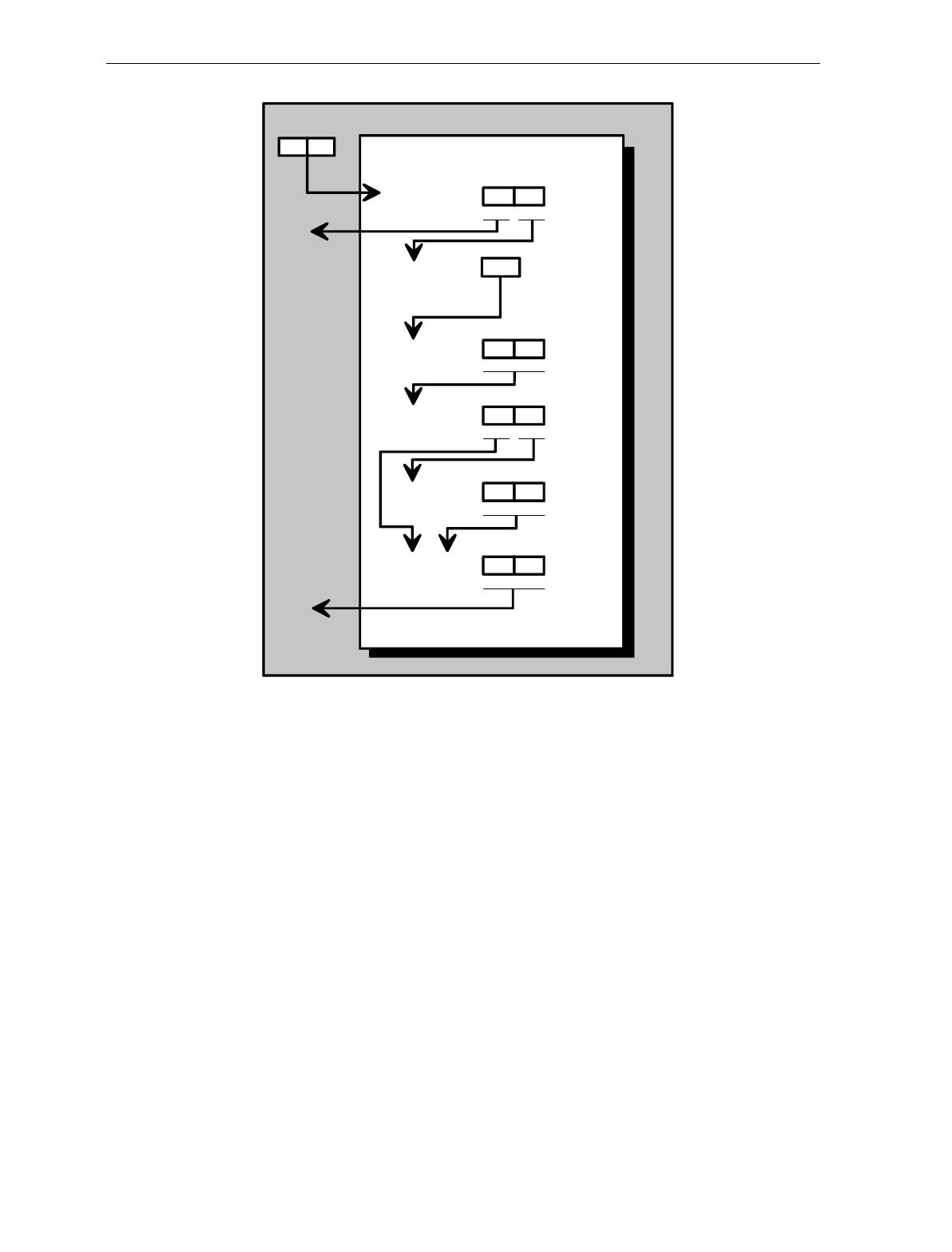
7-10 Chapter 7: Programming
11722
BASE PROGRAMMING STATE
Code 39
Bar Codes - 2
Full ASCII
Minimum
Characters
Allowed
Check Digit
Present 10
Disable Enable
Transmit
Check Digit 01
Disable Enable
01
Disable Enable
1
0
Disable Enable
2-F
4
1
Allow Single
Character
Tags
01
Disable Enable
b) Enter Specific Parameters
To enter only one particular parameter in a Specific
Programming Mode, scan the two numbered Hex tags that
correspond to that specific mode. However, once you have
entered the specific programming mode instead of immediately
changing parameters with numbered Hex tags, use the lettered
Hex tags to choose the one particular parameter that you want
to change. After you have selected the new parameter setting,
the scanner immediately returns to the Base Programming
State. If you decide to do additional programming with these
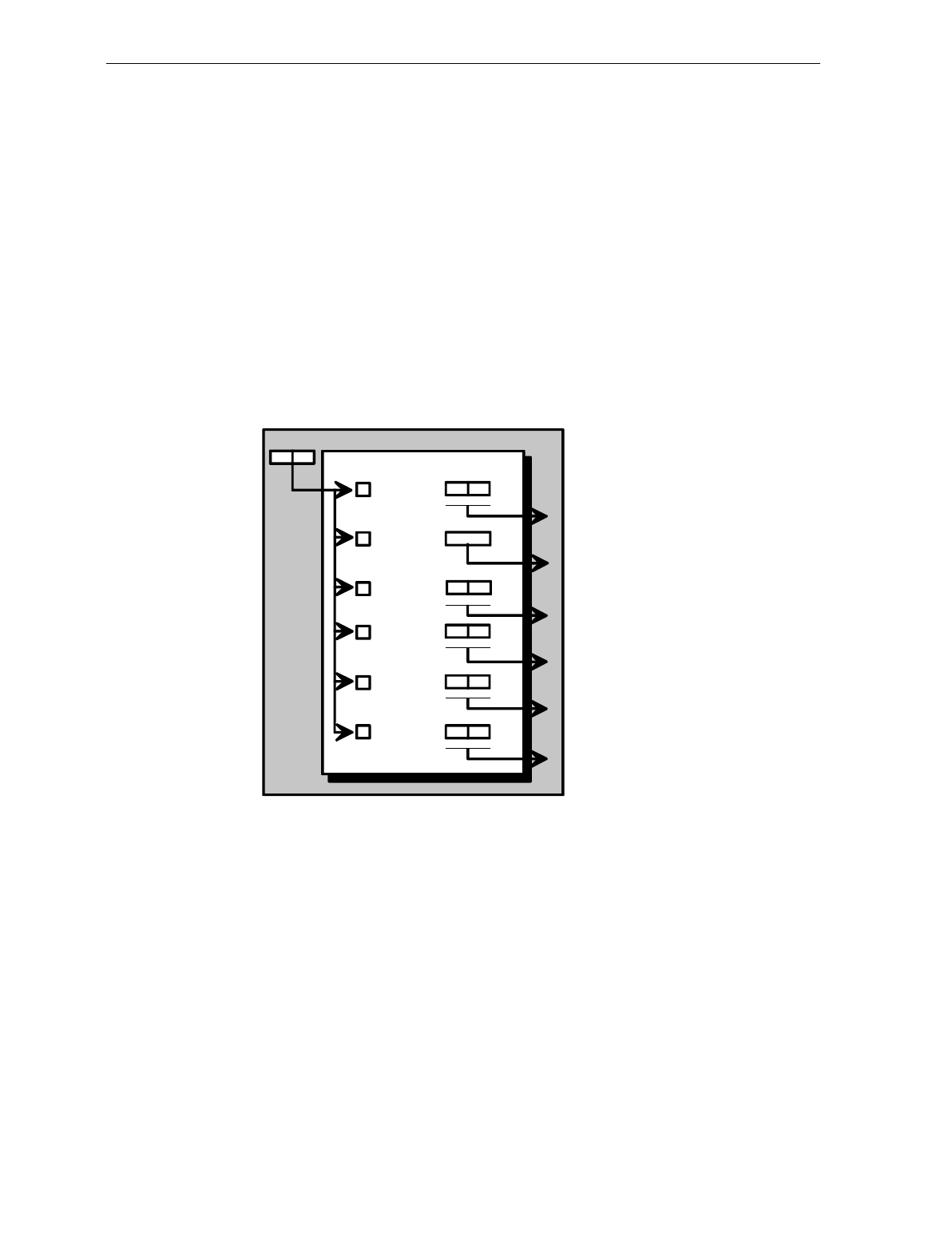
Chapter 7: Programming 7-11
parameter options, you have to re-enter the Specific
Programming Mode by scanning the two Hex tags again.
The following figure shows how to proceed through a Specific
Programming Mode where you change only one of the
parameters. This figure presents the specific programming
mode for Bar Codes 2 program parameters. Notice that once
you have entered the Specific Programming Mode, if you scan
the Hex A, Hex B, Hex C, Hex D, Hex E, or Hex F tag, you can
enter the specific parameters that correspond to that tag. After
you record the parameters, the scanner immediately returns to
the Base Programming State. To return to programming, you
scan the Hex 1 and Hex 4 tags again and re-enter the Specific
Programming Mode. From this point, you can enter either all
parameters or another specific parameter.
11723
BASE PROGRAMMING STATE
41
Code 39
Bar Codes - 2
Full ASCII
Minimum
Characters
Allowed
Check Digit
Present
Transmit
Check Digit
A
B
C
D
E
10
Disable Enable
01
Disable Enable
10
Disable Enable
2- F
01
Disable Enable
Allow Single
Character
Tags
F01
Disable Enable
For example:
Full ASCII is programmed by scanning, in
sequence, the Hex 1, Hex 4, Hex C, and
Hex 1 tags. The other parameters are left
in original state.
5. Repeat step 3 and step 4 until all parameters are entered.
6. Scan the Save and Reset tag. All parameter changes are saved and
NCR 7870 is reset (goes through initial power-up sequence). The
NCR 7870 now operates using the new program.

7-12 Chapter 7: Programming
Programming Tips
• Turn the host terminal off or disconnect all interface cables to the
NCR 7870 before entering your program. Some host terminals can
corrupt your program if they are running and are connected to the
NCR 7870 while you are entering the program.
• To exit a Specific Programming Mode without entering all the
parameters, scan the Abort tag. All parameters entered are
retained and the NCR 7870 returns to the Base Programming State.
To save the changed parameters, you must scan the Save and Reset
tag.
• To exit the programming mode without saving any parameter
changes, scan the Abort tag while in the Base Programming State.
The NCR 7870 goes through initial startup and operates using the
old program.
• If you do not know how your NCR 7870 is programmed, set all
parameters to default values, then enter any required changes. Do
this by scanning the Default tag as the first tag after applying
power to the NCR 7870. Next, scan the Programming Mode tag to
enter the Base Programming State and enter your programming
changes.
• After completing a programming sequence, wait for the tone or
Voice Message to indicate the unit is back in Programming Mode
before beginning the next programming sequence.
Note: Some parameters do not have default values and are not
changed when you scan the Default tag.

Chapter 7: Programming 7-13
Program Parameter Descriptions
Within the Base Programming State are several Specific Programming
Modes. Each of these have specific programming parameters.
Communications Protocol
The Communications Protocol programming mode selects the protocol
that the NCR 7870 Scanner/Scale uses to communicate with the host
terminal.
Note: The factory sets the Communications Protocol according to the
specifications on your order. Before changing the Communications
Protocol, the NCR 7870 must contain the correct Communications
Interface Board. Also, since there is no default Communications
Protocol, the Default tag does not change this parameter.
Defaults
Parameter Default Value
Protocol No Default
Specific Program Parameters
OCIA NCR Short (Datachecker) – Hex 0 tag
NCR short format OCIA is the scanner only (NCR 7870-1000/3000)
protocol used in older NCR terminal systems such as 2557 and 2126
systems. Later model terminals may also use this format for scanner
only configurations. If the scale is enabled (NCR 7870-
2000/4000/4500), a system using the short format OCIA protocol uses
the OCIA Dual-Cable setting as explained under OCIA Dual-Cable.
This format accommodates only 5 data bits per character and supports
only UPC/EAN bar code data.

7-14 Chapter 7: Programming
A scanner or scanner/scale that uses the Datachecker Interface should
be programmed using this format. If the protocol information is lost,
the scanner/scale defaults to RS-232. It then must be reprogrammed to
OCIA NCR Short. Use the Hex 0 tag to enable this protocol.
OCIA NCR Long – Hex 1
OCIA Long (Alternate Codes Long Format) is used on the NCR 7852
Alternate Codes Scanner and the NCR 7890 Presentation Scanner. This
format originally supported only single byte commands from the host
terminal due to scanner limitations. The OCIA NCR Long format
sends ASCII tag data to the host terminal. Since this format supports 8
data bits, it can accommodate the alphanumeric data found in the
Code 128 and Code 39 bar codes, provided the system software
supports those codes. This data format cannot accommodate scale
communications and is not the same as the data format used in Single
Cable OCIA, even though both formats use long format OCIA
hardware. Use the Hex 1 to enable this protocol.
OCIA Non NCR Dual Cable – Hex 2
The Non NCR Dual Cable configuration uses two separate cables for
the scanner and the scale. The scanner data protocol is the same as in
the OCIA Non NCR protocol. The scale data protocol is the same as is
used on OCIA Dual Cable scale communications (OCIA NCR Short).
Use the Hex 2 tag to enable this protocol.
IBM 468x/9x Port 4A (Slot Scanner) – Hex 3 tag
All models of the NCR 7870 support the IBM 468x/9x format and use
the same protocol found on IBM terminals. The scanner uses terminal
port 17 and the select address is set to 4A.
If your unit is a scanner/scale, the IBM address default setting is 6E,
but can be programmed to 6A or 6B. The IBM terminal integrated
scanner/scale driver normally uses address 6E. However, if the
scanner works but the scale does not, try using the other two scale
addresses. Use the Hex 3 tag to enable this protocol.

Chapter 7: Programming 7-15
IBM 468x/9x Port 4B (HHBCR) – Hex 4 tag
All models of the NCR 7870 support the IBM 468x/9x format and use
the same protocol found on IBM terminals. The scanner uses terminal
port 17 and the select address is set to 4B. Use this protocol with the
hand held bar code reader.
If your unit is a scanner/scale, the IBM address default setting is 6E,
but can be programmed to 6A or 6B. The IBM terminal integrated
scanner/scale driver normally uses address 6E. However, if the
scanner works but the scale does not, try using the other two scale
addresses. Use the Hex 4 tag to enable this protocol.
RS-232 – Hex 5 tag
RS-232 is used to connect the scanner or scanner/scale to almost any
RS-232 type of communications device. This protocol uses 7-bit ASCII
to send tag and scale data to the device. Use the Hex 5 tag to enable
this protocol.
OCIA Single Cable – Hex 6 tag
The OCIA Single-Cable scanner/scale format is the format normally
used in supermarkets to talk to an NCR 7870 Scanner/Scale. Since this
format supports 7-bit data, it can accommodate the alphanumeric data
found in the Code 128 and Code 39 bar codes, provided the system
software also support those codes. Use the Hex 6 tag to enable this
protocol.
OCIA NCR Dual Cable – Hex 7 tag
The OCIA NCR Dual Cable configuration uses two separate cables for
the scanner and scale. The data protocol is the same as in OCIA NCR
Short. This dual cable communications scheme is used on older NCR
terminal systems such as 2557 and 2126 systems. This format can
accommodate only 5 data bits per character and supports only
UPC/EAN bar code data. Use the Hex 7 tag to enable this protocol.

7-16 Chapter 7: Programming
Casio 4-Bit, Parallel, Dual Cable – Hex A tag
Non-NCR short format is used on some older competitive terminal
systems. This format is sometimes called 6-bit ASCII since it can
accommodate only 6 data bits per character. It cannot support
Code 128 or Code 39 bar code data. This format is normally not used
on NCR systems. Use the Hex A tag to enable this protocol.
IBM 1520 (BRC, IBM 468x/9x Port 4B) – Hex B tag
All models of the NCR 7870 support the IBM 468x/9x format and use
the same protocol found on IBM terminals. The scanner uses terminal
port 17 and the select address is set to 4B.
If your unit is a scanner/scale, the IBM address default setting is to 6E,
but can be programmed to 6A or 6B. The IBM terminal integrated
scanner/scale driver normally uses address 6E. However, if the
scanner works but the scale does not, try using the other two scale
addresses. Use the Hex B tag to enable this protocol.
TEC, 4-Bit, Parallel, Dual Cable – Hex C tag
The TEC 4-Bit Parallel protocol is used when connecting the NCR 7870
Scanner/Scale to a TEC M-XXXX host terminal. This configuration
uses two cables. The scanner uses an OCIA interface and the scale uses
a 4-bit parallel interface. Use the Hex C tag to enable this protocol.
Chapter 7: Programming 7-17
Communications Protocol Hex Tag Summary
Communications Protocol Type Hex Tag
OCIA NCR Short (Datachecker) 0
OCIA NCR Long 1
OCIA Non-NCR Dual Cable 2
IBM 468x/9x Address 4A 3
IBM 468x/9x Address 4B (HHBCR) 4
RS-232 5
OCIA Single Cable 6
OCIA NCR Dual Cable 7
Casio 4-Bit, Parallel, Dual Cable A
IBM 1520 (BRC, IBM 468x/9x Port 4B) B
TEC, 4-Bit, Parallel, Dual Cable C
Programming Example
Following is an example of a completed Communications Protocol
worksheet. In this example, RS-232 is the selected protocol.
Your Program
Communications
Protocol
10
Protocol
5
R0064

7-18 Chapter 7: Programming
Good Read Tone
The Good Read Tone programming mode selects the parameters for
sounding a tone each time the NCR 7870 Scanner/Scale successfully
reads a bar code. It also controls the volume of the Not-On-File tone.
This mode contains five shortcuts: A, B, C, D, and E. After entering
this programming mode, you normally go directly to a specific
parameter by scanning the appropriate shortcut Hex tag. This
eliminates the need to enter all parameters when only one needs
changing.
Defaults
Parameter Default Value
Tone On/Off On
Tone Frequency No Default
Tone Length No Default
Tone Volume No Default
Not-on-File Tone No Default
Specific Program Parameters
Not On File Tone Volume
The Hex E tag permits you to select the volume of the Not
On File Tone by listening to it as you repeatedly scan the
Hex E tag. The new tone sounds for two seconds. End this
mode by scanning the End tag or another valid Hex tag.
Tone Frequency (Hertz)
The Hex B tag permits you to set the frequency of the Good Read Tone
by listening to it. Each time the Hex B tag is scanned, the tone
increments one unit. After reaching the highest frequency (1250
Hertz), the sequence starts over with the lowest frequency (524 Hertz).
End this mode by scanning the End tag or another valid Hex tag.
Chapter 7: Programming 7-19
Tone Length (Milliseconds)
The Hex C tag permits you to set the length of the Good Read Tone by
listening to it. Each time you scan the Hex C tag, the tone length
changes from a minimum of 25 milliseconds to a maximum of 250, and
then back again. End this mode by scanning the End tag or another
valid Hex tag.
Tone On/Off
The Hex A tag sets the Tone On/Off programming mode,
which offers two options, On and Off. The Hex 0 tag turns
the Good Read tone off and the Hex 1 tag turns the Good
Read Tone on. The default is to turn the Good Read Tone on.
Tone Volume
The Hex D tag permits you to select the volume of the Good Read tone
by listening to it as you repeatedly scan the Hex D tag. End this mode
by scanning the End tag or another valid Hex tag.
Program Example
Following is an example of a completed Good Read Tone
programming worksheet. In this example, the only selection that can be
made beforehand is the tone on/off, which is selected to be on. The
other adjustments are selected by listening to the tone as you
repeatedly scan the appropriate Hex tag.
Your Program
1
Frequency
Tone
B
Tone
Length
C
Tone
Volume
D
11BCD
** *
Not-On-File
Tone Volume
E
E*
* Scan Hex tag repeatedly for desired setting.
Tone
On/Off
A
B052
Good Read Tone
*

7-20 Chapter 7: Programming
Timers The Timers programming mode controls the two NCR 7875
Scanner/Scale timers: Lockout Time and Active Time.
Defaults
Parameter Default Value
Lockout Time 900 milliseconds
Restart Lockout Timer Off
Active Time 15 seconds
Specific Program Parameters
Lockout Timer (Milliseconds)
The lockout timer prevents the scanner/scale from repeatedly reading
the same bar code. After reading a bar code, it must be removed from
the scan pattern and the time programmed in the lockout timer must
elapse before the scanner/scale can read the same bar code again. The
Lockout Time parameter selects the lockout time.
There are 8 different times ranging from 450 milliseconds to
1500 milliseconds in increments of 150 milliseconds. Select these times
using the Hex 0 through Hex 7 tags. The default time is
900 milliseconds.
Restart Lockout Timer
The Restart Lockout Timer parameter controls restarting the
lockout timer each time the scanner/scale reads the same bar
code. Turning on the Restart Lockout Timer option has the
following effect. After reading a bar code, if the bar code
moves out of the scan pattern and then back into the scan
pattern before the lockout timer times out, the lockout timer
restarts. The Hex 0 tag turns off this option and the Hex 1
tag turns it on. The default is off.
Chapter 7: Programming 7-21
Active Time (Minutes)
You can program specific lengths of time that your NCR 7870
Scanner/Scale stays on after the last good read. There are four options
in the Active Time parameter: no shut down, shut down after 15
minutes, shut down after 30 minutes, and shut down after 60 minutes.
Select these times using the Hex 0 through Hex 3 tags, respectively.
The default time is 15 minutes. Selecting no shut down results in the
scanner/scale being active all the time.
Note: NCR suggests that you do not set the Active Time parameter to
“no shut down.” Leaving the laser light on all the time reduces its life
expectancy.
Program Example
Following is an example of a completed Timer programming
worksheet. In this example the time-outs are programmed for the
following.
• Lockout Time – 900 milliseconds
• Restart Lockout Timer – off
• Active Time – 30 minutes
Your Program
11814
A
Lockout
Time
3
B
Timer
Restart
0
C
Active
Time
2
Timers
1 2

7-22 Chapter 7: Programming
Bar Codes – 1 The Bar Codes 1 programming mode contains programming
parameters for UPC/EAN bar codes.
Defaults
Parameter Default Value
UPC/EAN Enable
Version D None
Extend UPC-A to EAN-13 Disable
Extend UPC-E to UPC-A Disable
Periodic Codes Disable
Periodic Codes Extension 2-Digit & 5-Digit
Send Data Data as Decoded
Specific Program Parameters
UPC/EAN
The UPC/EAN parameter controls reading UPC/EAN bar codes.
Disable reading UPC/EAN bar codes by scanning the Hex 0 tag and
enable reading by scanning the Hex 1 tag. The default is to enable
reading.
If you choose to disable reading UPC/EAN bar codes, there are no
other entries allowed for this parameter. However, if you enable
reading UPC/EAN bar codes, you can program the remaining
parameters.
Version D
The Version D parameter permits you to enable or disable reading
UPC Version D bar codes. There are six choices: None, D-1, D-2, D-3,
D-4, and D-5. Scan the appropriate Hex 0 through Hex 5 tag to input

Chapter 7: Programming 7-23
this parameter. The default is None and scanning a valid Hex tag ends
the input for this parameter option.
Extend UPC-A to EAN-13
The Extend UPC-A to EAN-13 parameter determines whether to pad
the tag data, changing 12-digit UPC tags to 13-Character EAN tags.
The program does this by putting a zero (0) at the front of the tag data.
Scan the Hex 0 tag to disable this option or the Hex 1 tag to enable it.
The default is Disable and scanning a valid Hex tag ends the input for
this parameter option.
Extend UPC-E to UPC-A
The Extend UPC-E to UPC-A parameter determines whether to pad the
tag data, changing 6-digit truncated UPC tags to 12-Character UPC-A
tags. Scan the Hex 0 tag to disable this option or the Hex 1 tag to
enable it. The default is Disable and scanning a valid Hex tag ends the
input for this parameter option.
Periodic Codes
The Periodical Codes parameter controls the processing of Periodical
Codes. Disable Periodical Codes by scanning the Hex 0 tag and enable
them by scanning the Hex 1 tag. The default is to disable Periodical
Codes.
If you choose to disable Periodical Codes, there are no other entries
allowed for this parameter. Scanning the Hex 0 tag also causes the
scanner/scale to go back to the Base Programming State. However, if
you enable Periodical Codes, you must also program the Periodical
Code Extension and Send Data parameters.
Note: Use of optional add-on bar codes may require additional
programming. See Early Beep Disable and Terminal Coupon Interface
Parameters in the Special Programming section of this chapter.
Periodic Code Extension
The Periodical Code Extension parameter has three selections: 2-digit
extension only, 5-digit extension only, and either 2- or 5-digit
extensions. Scan the Hex 0 tag for 2-digit extension only, the Hex 1 tag
for 5-digit extension only, or the Hex 2 tag for both the 2- and 5-digit
7-24 Chapter 7: Programming
extension. The default is 2- and 5-digit extensions and scanning a valid
Hex tag causes the program to go to the next parameter option.
Send Data
The Send Data parameter has three selections: Data As Decoded,
Periodical Code Data Only, and CF Hex If Periodical Data Not
Decoded. If you scan the Hex 0 tag, the data is sent as decoded,
whether or not there are extension digits. If you scan the Hex 1 tag,
only valid periodical codes are sent. If you scan the Hex 2 tag, a
hexadecimal CF is sent as the extension if the scanner/scale could not
read a 2- or 5-digit code. The default is Data as Decoded. Scanning a
valid Hex tag causes the program to go to the Base Programming State.
Program Example
In this example the UPC/EAN bar codes are programmed to have:
• UPC/EAN – enabled
• Version D tags – not read
• Extend UPC-A to EAN-13 – disabled
• Extend UPC-E to UPC-A – disabled
• Periodical Codes – enabled
• Periodical Code Extensions – 2- and 5-digit extensions
• Send data data – as decoded
Your Program
0
Version
D
B
0
Extend
UPC-A
C
0
Extend
UPC-E
D
1
Periodical
Codes
E
2
Periodical
Code
Extension
0
Send
Data
Bar Codes - 1
1 3 1
UPC/EAN
A
B055

Chapter 7: Programming 7-25
Bar Codes – 2 The Bar Codes 2 programming mode contains programming
parameters for Code 39.
Defaults
Parameter Default Value
Code 39 Disable
Minimum Characters Allowed 8
Full ASCII Disable
Check Digit Present Disable
Transmit Check Digit Disable
Allow 1-or-2 Character Tags Disable
Specific Program Parameters
Code 39
The Code 39 parameter controls reading Code 39 bar codes. Disable
reading Code 39 bar codes by scanning the Hex 0 tag and enable
reading by scanning the Hex 1 tag. The default is to disable reading.
If you choose to disable reading Code 39 bar codes, there are no other
entries allowed for this parameter. However, if you enable reading
Code 39 bar codes, you can program the rest of the parameters.
Minimum Characters Allowed
The Minimum Characters Allowed parameter defines how many
characters in a bar code must be read the same by two separate scans
before determining a valid read has occurred. You should set this
option to the number of characters in a typical tag. This ensures that
the scanner/scale reads typical tags with at least two complete good
scans before sending the tag data to the host terminal.

7-26 Chapter 7: Programming
There are 15 selections for this parameter option (2 through 16
characters). Scan the proper Hex tag (Hex 2 through Hex F) to enter
your selection. The default is 4 characters.
Full ASCII
Code 39 permits full ASCII capability by encoding the additional
characters. Disable this function by scanning the Hex 0 tag, and scan
the Hex 1 tag to enable this function. Disable is the default.
Check Digit Present
The Check Digit Present parameter permits you to determine if the bar
code must contain a correct check digit to be identified as valid. If this
function is enabled, the bar code is ignored if a check digit is not
present. Scan the Hex 0 tag to disable this option, or the Hex 1 tag to
enable it. Disable is the default.
Transmit Check Digit
The Transmit Check Digit parameter selects whether to send the check
digit to the host terminal. Scan the Hex 0 tag to disable this option, or
the Hex 1 tag to enable it. The default is to disable sending the check
digit.
Allow 1- or 2-Character Tags
The Allow One- or Two-Character Tags parameter selects whether or
not to permit the scanner to read a one- or two-character Code 39 label.
If your application does not require that the scanner read a one- or
two-character Code 39 label, scan the Hex 0 tag to disable this option.
If your application requires this capability, scan the Hex 1 tag to enable
it. The default is to disable reading a one- or two-character Code 39
label.

Chapter 7: Programming 7-27
Program Example
Following is an example of a completed Bar Codes 2 programming
worksheet. In this example, Code 39 is enabled with the following
options.
• Code 39 – enabled
• Minimum Characters Allowed – 5
• Full ASCII – disabled
• Check Digit Present – enabled
• Transmit Check Digit – enabled
• Allow One- or Two-Character Tags – disabled
Your Program
Bar Codes - 2
1 4
A
Code 39
1
Minimum
Characters
Allowed
B
5
Full
ASCII
C
0
Check
Digit
Present
D
1
Transmit
Check
Digit
E
1
Allow
Single
F
0
Character
Tags
R0068

7-28 Chapter 7: Programming
Bar Codes – 3 The Bar Codes 3 programming mode contains programming
parameters for Interleaved 2 of 5.
Defaults
Parameter Default Value
Interleaved 2 of 5 Disable
Bar Code Length Range Check
Value 1 04
Value 2 16
Check Digit Present Disable
Transmit Check Digit Disable
Specific Program Parameters
Interleaved 2 of 5
The Interleaved 2 of 5 parameter controls reading Interleaved 2 of 5 bar
codes. Disable reading Interleaved 2 of 5 bar codes by scanning the
Hex 0 tag and enable reading by scanning the Hex 1 tag. The default is
to disable reading.
If you choose to disable reading Interleaved 2 of 5 bar codes, there are
no other entries allowed for this parameter. However, if you enable
reading Interleaved 2 of 5 bar codes, you can program the remaining
parameters.

Chapter 7: Programming 7-29
Bar Code Length
The Bar Code Length parameter selects the method for determining if
an Interleaved 2 of 5 bar code is a valid length. The Range Check
method identifies a length range by specifying the minimum and
maximum number of characters. The Specific Check method identifies
two specific bar code lengths by specifying the number of characters in
each. With this option, the number of characters in all
Interleaved 2 of 5 bar codes must be one of the two numbers. Scan the
Hex 0 tag to use the Range Check method, scan the Hex 1 tag to use the
Specific Check method. The default is the Range Check method.
Value 1 and 2
The Value 1 and Value 2 parameter specifies the valid
Interleaved 2 of 5 bar code lengths. Use this option with the Bar Code
Length parameter option described in Bar Code Length. If you select the
Range Check method, Value 1 specifies the minimum number of
characters in a valid Interleaved 2 of 5 bar code and Value 2 specifies
the maximum number of characters. If you select the Specific Check
method, Value 1 contains one specific number of characters and Value
2 contains another.
Accepted values for Value 1 and Value 2 are 4 to 38 readable
characters. The number of readable characters must be an even
number; if you specify an odd number, it is rounded down one. Each
value is input using two Hex tags. The first can be Hex 0 through
Hex 3 and the second can be Hex 0 through Hex 9. The default for
Value 1 is 08 and for Value 2 is 16
Check Digit Present
The Check Digit Present parameter permits you to determine if the bar
code must contain a correct check digit to be identified as valid. If this
function is enabled, the bar code is ignored if a check digit is not
present. Scan the Hex 0 tag to disable this option, or the Hex 1 tag to
enable it. Disable is the default.
7-30 Chapter 7: Programming
Transmit Check Digit
The Transmit Check Digit parameter selects whether to send the check
digit to the host terminal. Scan the Hex 0 tag to disable this option, or
the Hex 1 tag to enable it. The default is to disable sending the check
digit.
Program Example
Following is an example of a completed Bar Codes - 3 programming
worksheet. In this example Interleaved 2 of 5 is programmed for the
following.
• Interleaved 2 of 5 – enabled
• Bar Code Length – range check method
• Minimum bar code length – 4 characters
• Maximum bar code length – 10 characters
• Check Digit Present – enabled
• Transmit Check Digit – enabled
Your Program
Bar Codes - 3
1 5
A
Interleaved
2 of 5
1
Bar Code
Length
B
0
Value 2
1 0
Check Digit
Present
C
1
Transmit
Check Digit
D
1
Value 1
0 4
R0069

Chapter 7: Programming 7-31
Bar Codes – 4 The Bar Codes 4 programming mode contains programming
parameters for Code 128 bar codes.
Defaults
Parameter Default Value
Code 128 Disable
Minimum Data Characters Allowed 3
UCC 128 Disable
Specific Program Parameters
Code 128
The Code 128 parameter contains two selections: Disable and Enable.
Disable reading Code 128 bar codes by scanning the Hex 0 tag and
enable reading by scanning the Hex 1 tag. However, selecting the
disable option does not prevent reading the programming tags that are
Code 128. The default is to disable reading Code 128 bar codes.
Minimum Data Characters Allowed
The Minimum Data Characters Allowed refers to the Code 128
characters on a numeric-only Code 128 symbol. For example, given a
numeric-only Code 128 symbol of 12 34 56 78, the Minimum Data
Characters Allowed would be 4; each Code 128 character is composed
of two numeric data characters. Enter your selection by scanning the
appropriate hex tag (Hex 1 through Hex 5). The default is three.
UCC 128
The UCC 128 option refers to the Uniform Code Council Code 128 Data
Formatter Start Code. Scan the Hex 0 tag to disable this function, or
the Hex 1 tag to enable it. The default is disable.
7-32 Chapter 7: Programming
Program Example
Following is an example of a completed Bar Codes 4 programming
worksheet. In this example the Code 128 bar codes are programmed
for the following.
• Code 128 – enabled
• Minimum Data Characters Allowed – 3
• UCC 128 – disabled
Your Program
A B
1 7
Code
128 Minimum
Data
Characters
Allowed
UCC
128
C
13 0
11808
Bar Codes - 4

Chapter 7: Programming 7-33
Label Identifiers
The Label Identifiers programming mode selects the parameters for
adding label identifiers to communication messages. If used with RS-
232 or OCIA NCR Long or OCIA NCR Short when reading UPC
Version D bar codes, the identifiers go before the bar code data. Label
identifiers for the other modes of communication are determined by
the firmware and are not programmable.
Defaults
Parameter Default Value
Identifier Type Default Prefix
Common Byte 1 5D
Common Byte 2 42
Bar Code Type No Default
Common Byte Common Byte 2 as a suffix for Code
39, Code 128, and Interleaved 2 of 5.
UPC and EAN do not use common
bytes.
Unique Identifier UPC-A-41 (ASCII A)
UPC-D-44 (ASCII D)
UPC-E-45 (ASCII E)
EAN-8-46 (ASCII F)
EAN-13-47 (ASCII G)
Code 39-31 (ASCII 1)
Code 128-33 (ASCII 3)
Interleaved 2 of 5 – 32 (ASCII 2)
Version Number (UPC-D) Do Not Include

7-34 Chapter 7: Programming
Specific Program Parameters
Identifier Type
The Identifier Type parameter defines the type and placement of label
identifiers. You can select default identifiers that prefix the message
data, unique prefix identifiers, or no identifiers.
Select the Identifier Type parameter by scanning the appropriate tag
(Hex 0, Hex 2, or Hex 3). If you select default identifiers, you do not
enter any other parameter in this programming mode. The factory set
default is Default Prefix.
Identifier Types
1. Default Prefix - Scan the Hex 0 tag to use the default prefix. The
default label identifiers vary depending on the type of bar code
read. Following are the default identifiers for each bar code type.
a) UPC-A
41H NS X1 X2 X3 X4 X5 X6 X7 X8 X9 X10 CK
b) UPC-E
45H 30H X1 X2 X3 X4 X5 X6
c) EAN-8
46H 46H X1 X2 X3 X4 X5 X6 X7 CK
d) EAN-13
46H X1 X2 X3 X4 X5 X6 X7 X8 X9 X10 X11 X12 CK
e) Code 39
42H 31H X1 X2 X3 X4 X5 X6 X7 X8 X9 X10 X11 X12 X13 X14 X15 X16 X17
X18 X19 X20 X21 X22 X23 X24 X25 X26 X27 X28 X29 CK
f) Interleaved 2 of 5
42H 32H X1 X2 X3 X4 X5 X6 X7 X8 X9 X10 X11 X12 X13 X14 X15 X16 X17
X18 X19 X20 X21 X22 X23 X24 X25 X26 X27 X28 X29 CK
g) Code 128
42H 33H X1 X2 X3 X4 X5 X6 X7 X8 X9 X10 X11 X12 X13 X14 X15 X16 X17
X18 X19 X20 X21 X22 X23 X24 X25 X26 X27 X28 X29 CK
Chapter 7: Programming 7-35
2. None -- Scan the Hex 2 tag to select none. No label identifiers are
added to the message data.
3. Unique Prefix – - To use a unique prefix, scan the Hex 3. A Unique
Identifier is associated with each bar code type. Also, you may use
one, two, or no Common Bytes. The figure shows the possible
message formats when using a unique prefix. The formats do not
show other elements programmed in the other RS-232
programming modes.
Unique Prefix - All Bar Codes
Unique Identifier Bar Code Data
Common Byte 1 Unique Identifier Bar Code Data
Common Byte 2 Unique Identifier Bar Code Data
Common Byte 1 Common Byte 2 Unique Identifier Bar Code Data
Unique Prefix - UPC Version D
Unique Identifier Bar Code Data
Common Byte 1 Unique Identifier Bar Code Data
Common Byte 2 Unique Identifier Bar Code Data
Common Byte 1 Common Byte 2 Unique Identifier Bar Code Data
Unique Identifier Bar Code DataVersion Number
Common Byte 1 Unique Identifier Bar Code DataVersion Number
Common Byte 2 Unique Identifier Bar Code DataVersion Number
Common Byte 1 Common Byte 2 Unique Identifier Bar Code DataVersion Number
R0147
Common Byte 1 and Common Byte 2
The Common Byte 1 and Common Byte 2 parameters permit you to
specify the data sent to the host terminal in the Common Byte fields.
Enter this information as two Hex characters for each Common Byte.

7-36 Chapter 7: Programming
Note: Refer to the ASCII Code Chart for the Hex Characters; however,
values of 20 to 7E are recommended. Do not use the same characters as
the Terminator Byte or the message may terminate too soon. Also, a
Common Byte cannot be 00.
If you are not going to use a Common Byte, you can scan any Hex tag
twice except Hex 0 or the Terminator Byte value. The default for
Common Byte 1 is 5D (ASCII ]) and the default for Common Byte 2 is
42 (ASCII B). You must scan four tags to go to the next parameter.
Bar Code Type
The Bar Code Type parameter selects the bar code type for entering its
associated label identifier information. After entering a Bar Code Type,
enter the Common Byte, Unique Identifier, and Version Number if
applicable. This procedure repeats until the label identifiers are
specified for each bar code type. Scan the Hex 0 through Hex 7 tag to
enter the appropriate Bar Code Type. Since you must select each of
these individually for your application, there is no default for this
parameter.
Common Byte
The Common Byte parameter selects which common bytes, if any, to
add to the bar code data message. Each entry is unique to the
previously specified Bar Code Type. Scan the Hex 0 tag for no
Common Bytes, the Hex 1 tag for Common Byte 1, the Hex 2 tag for
Common Byte 2, or the Hex 3 tag for both Common Bytes. The default
for this parameter uses Common Byte 2 as a suffix for Code 39,
Code 128, and Interleaved 2 of 5 bar code data. UPC and EAN bar
codes do not use Common Bytes.
Unique Identifier
The Unique Identifier parameter permits you to specify the data sent to
the host terminal in the Unique Identifier field. Each entry is unique to
the previously specified Bar Code Type. Enter this data as two Hex
characters using recommended values of 20 to 7E (Refer to the ASCII
Code Chart). The following are the default values.

Chapter 7: Programming 7-37
Parameter Default Value
UPC – A 41 (ASCII A)
UPC – D 44 (ASCII D)
UPC – E 45 (ASCII E)
EAN – 8 46 (ASCII F)
EAN – 13 47 (ASCII G)
Code 39 31 (ASCII 1)
Code 128 33 (ASCII 3)
Interleaved 2 of 5 32 (ASCII 2)
Note: If you use the same characters as in the Terminator Byte, the
message may terminate too soon.
Version Number (UPC-D Only)
The Version Number parameter can be used only if you specified UPC-
D as the bar code type. To include the Version Number in ASCII, scan
the Hex 1 tag; scan the Hex 0 tag if you do not want to include the
Version Number. The default is not to include it.
Program Example
Following is an example of a completed Label Identifiers programming
worksheet. This example shows the following programmed selections.
• Identifier Type – Unique Prefix added to all bar code data messages
• Common Byte 1 – 5B ([)
• Common Byte 2 – 42 (B)
• Bar Code Type UPC-A
• Common Bytes – Common Byte 1
• Unique Identifier – 48 (H)
7-38 Chapter 7: Programming
• Bar Code Type UPC-D
• Common Bytes – No Common Bytes
• Unique Identifier – 41 (A)
• Version Number – included
• Bar Code Type Code 128
• Common Bytes – Common Byte 1
• Unique Identifier – 43 (C)
Your Program
NOTE: Scan the End tag to end the
Label Identifier Programming mode.
A
Identifier
Type
3
Common
Byte 1
B
B
5
Label Identifier
1 6
C
Common
Byte 2
4 2
D
Bar Code
Type
1
0
6
Common
Byte
1
0
1
Unique
Identifier
4
4
4
8
1
3Version
Number
1
R0071

Chapter 7: Programming 7-39
RS-232 Parameters – 1
The RS-232 Parameters 1 programming mode contains four of the
parameters required for RS-232 communications. From this
programming mode you can select the Baud Rate, Parity, Stop Bits and
Character Length, and Handshake Options.
Defaults
Parameter Default Value
Baud Rate 9600
Parity Odd
Stop Bits and Character Length 1 Stop Bit,
7-Bit Character
Handshake RTS High,
Wait for CTS
Specific Program Parameters
Baud Rate
The Baud Rate parameter contains seven selections: 300 Baud,
600 Baud, 1200 Baud, 2400 Baud, 4800 Baud, 9600 Baud, and
19200 Baud. Scan the appropriate Hex 0 through Hex 6 tag to set the
desired Baud rate. The default is 9600 Baud.
Parity
The Parity parameter contains three selections: Odd, Even, and None.
For 7-bit characters, bit 8 is the parity bit; for 8-bit characters, bit 9 is
the parity bit. Choosing no parity and 7-bit character length causes the
scanner/scale to send two stop bits; the scanner/scale must also
receive two stop bits. Scan the appropriate Hex 0, Hex 1, or Hex 4 tag
to select the desired Parity. The default is Odd.

7-40 Chapter 7: Programming
When you apply power to an NCR 7875-2000, the reset function checks
the RS-232 Communications Parity programming. If the selection is
None, it is ignored and Odd parity is used. If Odd or Even is selected,
that selection is used.
Stop Bits and Character Length
The Stop Bits and Character Length parameter contains four selections:
1 Stop Bit and 7-Bit Character Length, 1 Stop Bit and 8-Bit Character
Length, 2 Stop Bits and 7-Bit Character Length, and 2 Stop Bits and 8-
Bit Character Length. Choosing no parity and 7-Bit Character Length
causes the scanner/scale to send two stop bits; the scanner/scale must
also receive two stop bits. If you select 8-Bit Character length and
parity, only one stop bit is sent. Scan the appropriate Hex 0 through
Hex 3 tag to set the Stop Bits and Character Length. The default is 1
Stop Bit and 7-Bit Character Length.
Handshake
The Handshake parameter contains six selections. When considering
these, note that the scanner/scale controls only RTS, it can monitor
CTS. The following list identifies each Handshake option.
• RTS is always low, CTS is ignored (Hex 0 tag).
• RTS is always high, CTS is ignored (Hex 1 tag).
• Scanner/scale raises RTS and waits for CTS to go high before
transmitting (Hex 2 tag).
• Scanner/scale raises RTS before transmitting and ignores the state
of CTS (Hex 3 tag).
• RTS is always low and scanner/scale waits for CTS to go high
before transmitting (Hex 4 tag).
• RTS is always high and scanner/scale waits for CTS to go high
before transmitting (Hex 5 tag).
Scan the appropriate Hex 0 through Hex 5 tag to set the Handshake
option. The default is RTS High Wait for CTS.

Chapter 7: Programming 7-41
Program Example
Following is an example of a completed RS-232 Parameters 1
programming worksheet. In this example the following are selected.
• Baud Rate – 9600 Baud
• Parity – Even
• Stop Bits and Character Length – 1 stop bit and 8 data bit character
length
• Handshake – Raise RTS and Wait For CTS
Your Program
02
RS-232
Parameters - 1
1
B
Parity
2
D
Handshake
5
A
Baud
Rate
1
C
Stop Bits And
Character Length R0072

7-42 Chapter 7: Programming
RS-232 Parameters – 2
The RS-232 Parameters 2 programming mode contains some of the
parameters required for RS-232 communications. From this mode you
can select BCC Options, Interface Control, and Check Digit.
Defaults
Parameter Default Value
BCC Options 7870-1000 & 3000 – Disable
7870-2000, 4000, & 4500 – Enable
Interface Control None
Check Digit Enable UPC-A
Enable EAN-8
Enable EAN-13
Disable UPC-E
Specific Program Parameters
BCC Options
The BCC Option parameter permits you to enable or disable the use of
BCC at the end of a message. When enabled, the BCC is the last
character sent and is the Exclusive OR of each byte sent prior to the
BCC, except the prefix byte. Scan the Hex 0 tag to disable the BCC
Option, or scan the Hex 1 tag to enable it. The default is disable for
NCR 7870-1000/3000 and enable for NCR 7870-2000/4000/4500.
Interface Control
The Interface Control parameter permits you to select how to control
the transfer of data between the scanner/scale and the host terminal.
The options are None, enable ACK/NAK, enable XOn/XOff, and
enable both ACK/NAK and XOn/XOff.

Chapter 7: Programming 7-43
If you enable ACK/NAK, each message sent to the host terminal must
be acknowledged before sending the next message. Receiving the
message properly causes an ACK to be sent, and if there are any errors,
a NAK is sent instead and the scanner/scale sends the message again.
Also, any valid message other than NAK or XOn/XOff, if enabled,
serves as an ACK as long as the message from the scanner/scale is
completed before the host terminal starts sending the valid message to
the scanner/scale.
An XOff message turns the scanner transmitter off until the
scanner/scale receives an XOn message. An XOn message can be
received at any time. If the scanner/scale is sending a message when it
receives an XOff, since these messages can be received any time, data
transmission stops after sending the current byte. When the
scanner/scale receives the next XOn it sends the remainder of the
message. The scanner/scale does not acknowledge XOff and XOn
messages with ACK or NAK messages.
You select the interface by scanning the appropriate Hex 0 through
Hex 3 tag. The default is None.
Check Digit
The Check Digit parameter permits you to control the transmission of
UPC-A, UPC-E, EAN-8, and EAN-13 check digits. Scan the
appropriate Hex 0 through Hex 3 tags to enable or disable UPC-A,
UPC-E, EAN-8, and EAN-13 check digits. The default is enable UPC-
A, EAN-8, and EAN-13 and disable UPC-E.
Note: Although this is an RS-232 Parameters worksheet, the Check
Digit parameter also applies to UPC-E when using OCIA
communications.
7-44 Chapter 7: Programming
Program Example
Following is an example of a completed RS-232 Parameters 2
programming worksheet. This example shows the following program
selections.
• BCC Option – enabled
• Interface Control – ACK/NAK
• Check Digit – enable UPC-A, UPC-E, EAN-8, and EAN-13
Your Program
2 1
RS-232
Parameters - 2
1
BCC
Options
A
1
Control
Interface
B
3
C
Check
Digit R0146

Chapter 7: Programming 7-45
RS-232 Prefix Byte
The RS-232 Prefix Byte programming mode controls the use of prefix
bytes. If you use an RS-232 Prefix Byte, it is the leading character in
each message sent to the host terminal. Following it is the message
data.
Defaults
Parameter Default Value
Prefix Byte Disable
ASCII Code 02
Specific Program Parameters
Prefix Byte
The Prefix Byte parameter contains two selections: Disable and Enable.
Scan the Hex 0 tag to disable the Prefix Byte, or the Hex 1 tag to enable
it. The default is Disable.
ASCII Code
The ASCII Code parameter permits you to specify what ASCII code to
use for the Prefix Byte. Enter your selection by scanning the
appropriate two Hex tags (shown in the ASCII Code Chart). You can
select any value from 01 through 0F; however, the recommendation is
that you use the Start Of Text (STX) ASCII Code which is 02 Hex. Scan
the two appropriate Hex tags (Hex 0 through Hex 7 for the first
character and Hex 0 through Hex F for the second). The default for this
parameter is 02.
7-46 Chapter 7: Programming
Program Example
Following is an example of a completed RS-232 Prefix Byte
programming worksheet. This example shows the Prefix Byte enabled,
and ASCII Code STX (02 Hex) transmits as the leading character of
each message sent to the host terminal.
Your Program
2 2
RS-232
Prefix Byte
1
Prefix Byte
A
0
Code
ASCII
B
2
R0074

Chapter 7: Programming 7-47
RS-232 Terminator Byte
The RS-232 Terminator Byte programming mode controls the use of
terminator bytes. If you use an RS-232 Terminator Byte, it goes at the
end of the message sent to the host terminal. If you included a BCC, it
follows the Terminator Byte and includes the Terminator Byte in the
calculation.
When you apply power to an NCR 7875-2000, the reset function checks
the RS-232 Communications Terminator Byte programming. If the
selection is Disable, it is ignored and an ETX (03) is automatically sent
with each message. If you select Enable, the ASCII code you
programmed is sent.
Defaults
Parameter Default Value
Terminator Byte Disable
ASCII Code 03
Specific Program Parameters
Terminator Byte
The Terminator Byte parameter contains two selections: Disable and
Enable. Scan the Hex 0 tag to disable the Terminator Byte, or the Hex 1
tag to enable it. The default is Disable.
ASCII Code
The ASCII Code parameter permits you to specify what ASCII code to
use for the Terminator Byte. Enter your selection by scanning the
appropriate two Hex tags (shown in the ASCII Code Chart). You can
select any value from 01 through 7F; however, the recommendation is
that you use the End Text (ETX) ASCII Code which is 03 Hex or
Carriage Return (CR) which is 0D. Scan the two appropriate Hex tags

7-48 Chapter 7: Programming
(Hex 0 through Hex 7 for the first character and Hex 0 through Hex F
for the second). The default for this parameter is 03.
Program Example
Following is an example of a completed RS-232 Terminator Byte
programming worksheet. This example shows the Terminator Byte
enabled and ASCII code CR (0D Hex) transmitted as the Terminator
Byte.
Your Program
A
Terminator Byte
1
B
Code
ASCII
0 D
RS-232
Terminator Byte
2 3
R0075

Chapter 7: Programming 7-49
RS-232 Communications Options
The RS-232 Communications Options parameters control the delay
between messages, and the format in which the scanner and host
terminal exchange tag data messages. The firmware is programmed to
accept one parameter at a time and then leave this programming mode.
Therefore, each of the parameters must be programmed separately.
Defaults
Parameter Default Value
Message Delay 10 millisecond Delay
Scanner or Scanner/Scale Format Determined by Model
Normal or Eavesdrop Mode Normal Mode
Beep at Scale Weight Transmission No Beep
Specific Program Parameters
Normal or Eavesdrop Mode
The normal mode is used for most RS-232 connections. However, an
eavesdrop mode is available to permit another device to monitor the
communications between the NCR 7875 and the host terminal. Scan
the Hex 6 tag to select the normal mode or the Hex 7 tag to select the
eavesdrop mode.
Message Delay
The Message Delay option permits you to choose the minimum time
the firmware waits before sending the next message. This permits
lowering CTS by the host terminal to inhibit data from the scanner. On
previous scanners this option was not available.
Previous to firmware numbered 497-0301951 the delay between
messages was zero milliseconds. This did not permit the terminal to
lower CTS to prevent a second message from being sent to the scanner.

7-50 Chapter 7: Programming
With 497-0301951 and higher, the default is 10 milliseconds minimum
delay between messages.
Messages can be delayed by the following times.
• 0 for no delay
• 1 for a 10 ms delay
• 2 for a 50 ms delay
Scanner or Scanner/Scale Format
The Scanner or Scanner/Scale Format option permits you to force the
data format to either scanner only format or scanner/scale format to
accommodate the host terminal. For example, in a dual-cable system,
the scanner data and the scale data are normally sent over separate
cables in a format designed for each device (scanner or scale). In some
circumstances a host terminal may not be able to handle the normal
format sent to it. In that case, selecting one of these options permits
you to use the other format.
The Model Number option in the Scale Parameters section overrides
this option. If you program this option, do it after the other parameter
or return here and change it again. This option effects the address and
function code in the message, but not the BCC. The choices for this
option are as follows.
• 4 for Scanner Only format
• 5 for Scanner/Scale format
The normal (default) format for scanner only tag data messages is as
follows.
• Scanner-Only Tag Data
• Message Format
Prefix Byte Label Identifier Tag Data PPD Terminator Byte BCC Byte
16564
Shading indicates optional information.

Chapter 7: Programming 7-51
Following is the normal (default) format for scanner/scale tag data
messages.
• Scanner/Scale Tag Data
• Message Format
Prefix Byte Label Identifier Tag Data PPD Terminator Byte BCC Byte
30 38
Add FC
16565
Shading indicates optional information.
The difference between the scanner only and the scanner/scale format
is that the scanner/scale format has an address and a function code
following the optional Prefix Byte. For more detailed information on
message formats refer to the NCR Scanner/Scale Interface
Programmer's Guide (BD20-1074-A).
Beep at Scale Weight Transmission
This parameter allows the scanner to signal the transmission of a scale
weight that was requested by the host terminal. Scanning the Hex 9
tag activates this feature and causes the unit to sound a Good Read
tone as the weight information is sent to the terminal.
7-52 Chapter 7: Programming
Program Example
Following is an example of a completed RS-232 Communications
Options programming worksheet. This example shows the following
programming selections.
• Message delay – 10 ms
• Format – Scanner only
• Normal or Eavesdrop – Normal Mode
• Scale Weight Transmission - Beep
Your Program
12164
24
RS-232
Communications
Options
Message
Delay
A
Scanner or
Scanner/Scale
Format
B
Normal or
Eavesdrop
Mode
C
Beep/No Beep
Scale Weight
Transmission
D

Chapter 7: Programming 7-53
Scale Parameters
The Scale Parameters programming mode controls specific parameters
associated with the NCR 7870-2000, 4000, 4500 Scales. You can use it to
identify if the NCR 7870 includes a scale, and to define the address if
the scale is connected to an IBM terminal.
Defaults
Parameter Default Value
Model Number No Default
9.995 kg/13.995 kg No Default
IBM Address Address 6E set by
selecting IBM 468x on
Communications
Protocol Worksheet
Specific Program Parameters
Model Number
The Model Number parameter specifies if your unit is an NCR 7870-
1000/3000 Scanner or an NCR 7870-2000, 4000, or 4500 Scanner/Scale.
This parameter is set at the factory and should not need changing
under normal circumstances. Scan the Hex 3 tag to specify that the
unit is an NCR 7875-2000, 4000, or 4500 (scanner and scale), or scan the
Hex 4 tag to specify the unit as being an NCR 7875-1000 or 3000
(scanner only). If you disable the scale on an NCR Scanner/Scale unit
by scanning the Hex 4 tag, the BCC option also changes to the
appropriate state.
IBM Address
When programming an NCR 7870-2000, 4000, or 4500 Scanner/Scale
for IBM communications, you must select the proper scale
communications address. Selecting the IBM 468x communications
7-54 Chapter 7: Programming
protocol sets the scale address to 6E; however, it may need to be
changed to 6A or 6B, depending on the IBM configuration in the
particular IBM customer retail application. Scan the Hex 5 tag for
address 6A, the Hex 6 tag for address 6B, or the Hex 7 tag for address
6E.
The IBM terminal integrated scanner/scale driver normally uses
address 6E. However, if the scanner works but the scale does not, you
should try using the other two scale addresses.
9.995 kg / 13.995 kg
The 9.995 kg / 13.995 kg parameter toggles between a maximum
weight of either 9.995 kg or 13.995 kg. Use the Hex B tag to toggle
between the two weights.
Program Example
Following is an example of a completed Scale Parameters
programming worksheet. This example shows the following
programming selections.
• Weight – displayed in kilograms
• Unit – NCR 7870-2000 Scanner/Scale
• IBM address – 6B
• 9.995 kg / 13.995 kg – the Hex B tag toggles this parameter
Your Program
R0140
30
Scale
Parameters Model
Number IBM
Address 9.995 kg /
13.995 kg

Chapter 7: Programming 7-55
Miscellaneous Parameters
The Miscellaneous Parameters programming mode controls
parameters associated with the NCR 7870-2000, 4000, and 4500 Scales
that do not fit easily into any of the other categories. The NCR 7870
firmware is programmed to accept one parameter at a time and then
leave this programming mode. Therefore, each of the parameters must
be programmed separately.
Defaults
Parameter Default Value
5-Second Weight Display Timer Enabled
IBM Tone Control Enabled
OCIA Price Display Enabled
IBM Rexmit Control Permanently Enabled
OCIA Blank Display in Price Mode Disabled
Enable/Disable Voice Messages No Default
IBM Tag Data Format Hex
Specific Program Parameters
5-Second Weight Display Timer
This timer controls how long a price is shown on the integrated or
remote display. The 5-Second Weight Display Timer will only work if
the NCR 7870 is in OCIA Price Display Mode. The OCIA Blank
Display may or may not be enabled –- it is optional.
When the 5-Second Weight Display Timer is enabled (which is the
default setting), the display will show a weight until the host terminal
sends a price. The price is displayed for no more than five seconds
before returning back to weight. The weight value will remain on the
display until new information is sent to the display, e.g. – an item is

7-56 Chapter 7: Programming
scanned or a weight change is registered by the scale. Use the Hex 2
tag to enable the timer.
When the 5-Second Weight Timer is disabled, the display will show a
weight value until the host terminal sends price information. The price
will remain on the display until new weight or price information is sent
to the display. Use the Hex 1 tag to disable the timer.
IBM Tone Control (Good Read Tone)
When you use an IBM terminal, this parameter determines what device
controls the tone. Scanning the Hex 4 tag enables this option and the
IBM terminal controls the tone. Scanning the Hex 3 tag disables this
option and the scale controls the tone.
OCIA Price Display
When you use an OCIA terminal, this parameter controls the price
display. If you select enable by scanning the Hex 6 tag, the scale
accepts and displays price information from the terminal. If you select
disable by scanning the Hex 5 tag, the scale does not accept or display
any price information.
IBM Rexmit Control
When you use an IBM terminal and the scale detects a bad message
from the terminal, this parameter controls how the original message
gets retransmitted. If you select enable by scanning the Hex 7 tag, the
scale retransmits the original message three times, and then terminates
the sequence. If you select forever by scanning the Hex 8 tag, the scale
retransmits the original message until it is accepted, or until the scale is
told to reset by the terminal. You should not use the enable selection
unless advised to do so by NCR to solve a problem.
OCIA Blank Display In Price Mode
When Price Display mode is enabled, the OCIA Blank Display in Price
Mode parameter controls how the scale reacts to blank screen
commands. If you select enable by scanning the Hex A tag, the scale
blanks the screen when it receives the command. If you select disable
by scanning the Hex 9 tag, the scale ignores the command.

Chapter 7: Programming 7-57
Enable/Disable Voice Messages
When you have the voice messages feature on your scanner/scale, the
Voice Messages Enabled/Disabled parameter toggles to enable or
disable the feature. If voice messages are enabled, you hear them at the
appropriate time. If they are disabled, you hear the beep tones instead.
The Hex D tag toggles this parameter between enabled and disabled.
There is no indication, visual or otherwise, of the state of the
enable/disable condition. If you do not hear the voice messages when
you expect to hear them, toggle this parameter. If you still do not hear
them, the problem could be in the programming ROM, the speaker
chip, or elsewhere.
IBM Tag Data Format
This option is included because most IBM devices that have a select
address of 4B require the bar code data to be transmitted as ASCII
characters. (For hand-held bar code readers, see Communications
Protocol Programming Mode.) Therefore, when selecting
Communications Protocol choice 4B, NCR recommends that you set
the tag format to ASCII. Use the Hex E tag to select hex and use the
Hex F tag to select ASCII. The hex format is the default.
Program Example
Following is an example of a completed Miscellaneous Parameters
programming worksheet showing the following programming
selections.
• 5-Second Weight Display Timer – disabled
• IBM Tone Control – disabled
• OCIA Price Display – enabled
• IBM Rexmit Control – 3 times
• OCIA Blank Display in Price Mode – enabled
• Enable/Disable Voice Messages – the Hex D tag toggles this
parameter
• IBM Tag Data Format – ASCII
7-58 Chapter 7: Programming
Your Program
Miscellaneous
Parameters
3 2
IBM Tone Control
3
OCIA Price Display
6
IBM Rexmit Control
7
OCIA Blank Display in Price Mode
A
Toggle Enable/Disable of Voice Messages
FIBM Tag Data Format
15-Second Weight Display Timer
D
11822

Chapter 7: Programming 7-59
PACESETTER Plus Information
The PACESETTER Plus optional feature of the NCR 7870
Scanner/Scale determines what is wrong with a bar code label, fixes it,
and then transfers the information to the host terminal. In addition, the
scanner keeps track of what is wrong with the labels.
Mode 1 - Inquiry
Mode 1 keeps the following tallies. Included are the maximum counts.
Tally Count Type Description Maximum
Count
C1 Good Reads 1,000,000
C2 No reads due to lack of a full label
(bars missing, folded label, etc.) 65,535
C3 Good reads with very highly
overprinted bars 65,535
C4 Good reads with very highly
underprinted bars 65,535
C5 Missing margins 65,535
Enter Mode 1 by scanning the Mode 1 tag. Tally counts are displayed
on the Integrated Display or the NCR 7825 Remote Display. First the
display shows the tally count number and the percentage of that count
to the number of good reads. Three seconds later the actual tally count
is displayed. This cycle continues every three seconds.

7-60 Chapter 7: Programming
C3 03.4
1136
Tally Count 3
3.4% of Good Reads
Tally Count = 1136
Note: These displays alternate every three seconds.
16566
Scanning the Mode 1 tag again changes the display sequence to the
next tally count. Continue to scan the Mode 1 tag to view all tally
counts. The tally count information is displayed in order according to
the tally count number (C1 – C5).
Exit Mode 1 by pressing the Scale Zero Button on the Operator Display
Panel or by scanning the Mode 2 tag.
Mode 2 - Real Time
Enter Mode 2 by scanning the Mode 2 tag.
The scanner goes off-line and disables the scale so that the integrated
display or the NCR 7825 Remote Display can show Ready 4 label.
Every subsequent scan until the scanner is powered off (or the Scale
Zero Button is pressed) causes the scanner to indicate the status of label
readability. The scanner can recognize missing bars in labels, highly
over/under printed labels, missing margins, or a no-read condition.
If you scan a UPC/EAN label for analysis, the display shows label
followed in one second by the display of the first half of the UPC/EAN
label. If the label is a version E, no second half is displayed, since the E
label is only six digits in length. After another two-second pause, the
display shows CODE xx where "xx" is a code number to indicate one of
the following.

Chapter 7: Programming 7-61
Codes Description
Code 00 Label was decoded without major problems.
Code x1 Label appears to be highly underprinted.
Code x2 Label appears to be highly overprinted.
Code x4 Label appears to have missing bars or margins.
Code x5 Label appears to be highly underprinted and to have
missing bars or margins.
Code x6 Label appears to be highly overprinted and to have
missing bars or margins.
Code 1x Decoding was difficult. May be due to inconsistent
printing.
Code 2x Fragmented or folded label or inconsistent printed.
Code 3x Decoding was difficult due to fragmented, folded, or
inconsistently printed label.
Code 98 Label cannot be decoded due to missing print lines.
Code 99 Label cannot be decoded. If a particular label shows
this code it should be analyzed more closely for out-of-
specification conditions, even though the label may
show a Code 00 when it does scan (printing may be
inconsistent).
Note: If a label displays a code other than Code 00, the label should be
tested further for being out of specification by using a symbol verifier.
Note: To exit Mode 2 and return to Normal Mode, press the Scale
Zero Button on the Operator Display Panel. To go from Mode 2 to
Mode 1, scan the Mode 1 tag.

7-62 Chapter 7: Programming
Mode 3 – Normal
Mode 3 is the normal operating mode. You can program the scanner to
add PACESETTER Plus information to the decoded UPC/EAN data
that is sent to the host terminal. Perform the following procedure to
enable or disable PACESETTER Plus information.
1. Scan the Programming Mode tag (must be first tag scanned after
power-up).
2. Scan the Hex 3 tag.
3. Scan the Hex 1 tag.
4. Scan the Hex 3 tag.
5. Scan the Hex 1 tag to disable PACESETTER Plus information, or the
Hex 2 tag to enable PACESETTER Plus information.
6. Scan the Save and Reset tag.
The PACESETTER Plus information describes the label readability
much the same way as described in Mode 2. However, the host
software must be capable of receiving the extra data being sent to it.
With OCIA and RS-232 communications, PACESETTER Plus
information is sent as trailer information. With IBM communications,
PACESETTER Plus information is sent as header information that is
located between the last Status byte and the first tag data byte in the
message. The PACESETTER Plus format is defined as the normal
UPC/EAN format with the following added.
OCIA RS-232 IBM
OCH, xyH, xzH 43H, 3yH, 3zH OCH, 0yH, 0zH
x = High nibble containing character parity depending on
communication format (or 0).
yz = Decoding code

Chapter 7: Programming 7-63
The EOM bit, if applicable, is in the last byte sent, not the last byte of
the label data. The Decoding Codes are specified in the following
table.
Decoding Codes
YZ Description
1 z Decoding was difficult. May be due to
inconsistent printing.
2 z Fragmented or folded label or inconsistent
printing.
3 z Decoding was difficult due to fragmented,
folded, or inconsistently printed label.
y 1 Label appears to be highly underprinted.
y 2 Label appears to be highly overprinted.
y 4 Label appears to have missing bars or margins.
y 5 Label appears to be highly underprinted and to
have missing bars or margins.
y 6 Label appears to be highly overprinted and to
have missing bars or margins.
0 0 Label was decoded without major problems.
9 9 If a particular label intermittently shows this
code, the label should be analyzed more closely
for out-of-specification conditions, even though
the label may show a Code 00 when it does scan
(printing may be inconsistent).

7-64 Chapter 7: Programming
Host Access to Tallies
The host can send Long Format Codes, Short Format Codes, RS-232
Format Codes, and IBM 4683 Format Codes to read the scanner tallies.
The following table shows the Long Format Codes and the RS-232
Format Codes to use.
Tally Long Format Codes: OCIA and Single-Cable
Scanner/Scale OCIA RS-232 Codes
C1 00H, 33H, 3DH, 32H, 31H 33H, 3dH, 32H, 31H
C2 00H, 33H, 3DH, 32H, 32H 33H, 3dH, 32H, 32H
C3 00H, 33H, 3DH, 32H, 33H 33H, 3dH, 32H, 33H
C4 00H, 33H, 3DH, 32H, 34H 33H, 3dH, 32H, 34H
C5 00H, 33H, 3DH, 32H, 35H 33H, 3dH, 32H, 35H
Note: Parity, BCC, and so on, appropriate to the communication
protocol must be added.
Examples of Host Access to Tallies
Example 1
16823
30H b3H 3dH 32H b3H 8fH
30H 33H 3yH 3xH 3xH 3xH 3xH 3xH 3xH 3xH BCC (with EOM Bit)
The NCR 7870 response to the host request.
Host requesting tally C3 through single-cable OCIA.
Decimal digit with high order digit sent first
Tally count number
Block Check Character - an exclusive OR of all previous bytes
Presence of BCC specified by protocol
x =
y =
BCC =
Chapter 7: Programming 7-65
Example 2
16824
Host requesting tally C3.
The NCR 7870 response to the host request (tally count = 23,456
30H b3H 3dH 32H 8fHb3H
33H 34H 35H 36H BCC (with EOM Bit)30H 33H 30H 30H 32H 33H
Example 3
Scanner Address
Frame Counts
Scanner Status Bytes (3)
Pacesetter Plus Group Code
Seven Bytes BCD Data
Pacesetter Plus Function Code
CRC Bytes (2)
End Byte
Address
Frame
Request
CRC Bytes (2)
End Byte
An IBM host terminal request for tally C1.
The NCR 7870 response to the host request.
4A xx xx xx xx 32 00 00 02 03 04 05 06 31 xx xx 7E
4A xx 00 33 3D 32 31 xx xx 7E
16825

7-66 Chapter 7: Programming
Host Terminal request using short format codes:
Send Tally Count NCR OCIA Non-NCR OCIA
C1: 03H 0dH 01H 03H 4DH 21 H
With Parity & EOM 83H 0DH C1H
With Parity & EOM
C2: 03H 0dH 02H 03H 4DH E3H
03H 4DH 21H 83H 0DH C2H
With Parity & EOM
C3: 03H 0dH 03H 03H 4DH A3H
With Parity & EOM 83H 0DH 43H
With Parity & EOM
C4: 03H 0dH 04H 03H 4DH 65H
With Parity & EOM 83H 0DH 24H
With Parity & EOM
C5: 03H 0dH 05H 03H 4DH 65H
With Parity & EOM 83H 0DH 45H
With Parity & EOM
The NCR 7870 response to the host request.
00H 03H 0yH 0xH 0xH 0xH 0xH 0xH 0xH 0xH Parity & EOM bits added.
Decimal digit with high order digit sent first
Tally count number
x =
y = 16826
Example 4
Host request for tally C5 using short format codes:
Send Tally Count NCR OCIA Non-NCR OCIA
C5: 03H 0dH 05H 03H 4DH 65H
With Parity & EOM 83H 0DH 45H
With Parity & EOM
Chapter 7: Programming 7-67
The NCR 7870 response to the host request (tally count = 23,456):
Send Tally Count NCR OCIA Non-NCR OCIA
00H 03H 00H 00H
02H 03H 04H 05H
06H
C0H 03H C5H C0H
C0H 42H 03H 84H
C5H A6H C0H 03H
C0H C0H 42H 03H
84H C5H A6H C0H
03H C0H C0H 42H
03H 84H C5H A6H
With Parity & EOM
80H 83H 85H 80H
80H 02H 83H 04H
85H 46H
With Parity & EOM
Host Reset of Tallies
The host terminal can reset the tally counts using the Long Format
OCIA, Short Format OCIA, Single-Cable Scanner/Scale OCIA (parity
bits, EOM bits or BCC bytes are not shown), RS-232, and IBM 4683
formats. The OCIA and RS-232 command is given in the following
chart:
Host terminal request to reset tally counts (OCIA & RS-232)
OCIA RS-232
00H 03H 0DH xxH 44H 43H
XxH = 00H or BBC
(where protocol calls for BBC)
Address
Frame
Request
CRC Bytes (2)
End Byte
An IBM host terminal request to reset tally counts
4A xx 00 33 3D 3C 00 xx xx 7E
16827

7-68 Chapter 7: Programming
Special Programming
Some of the NCR 7870 features require programming that is somewhat
different than the normal programming.
Delay Weight Data to IBM Host Terminal
A timing condition is possible when the NCR 7870 Scanner/Scale
communicates with an IBM host terminal. The condition occurs when
the IBM Host is requesting weight data, but the scale is not settled. To
prevent the problem, you can enable a scale data delay function that
gives the scale more time to settle. The default for this parameter is to
disable the Scale Data Delay. Enable or disable the Scale Data Delay by
scanning the following sequence of programming tags as the first tags
scanned after applying power to the NCR 7870.
Enable – Programming Mode, Hex 4, Hex C, Hex E, Hex 2, Hex 9, Hex
4, Hex E, Hex 8, Hex 0, and Save and Reset.
Disable – Programming Mode, Hex 4, Hex C, Hex E, Hex 2, Hex 9, Hex
4, Hex E, Hex 0, Hex 0, and Save and Reset.

Chapter 7: Programming 7-69
EAN/JAN/UPC Multi-Symbol Scanning Parameters
The optional Multi-Symbol programming feature permits you to scan
bar code labels containing two or three EAN-13, JAN-13, or UPC-A
symbols.
Label Construction
A multi-symbol label must consist of any combination of two or three
EAN-13, JAN-13, or UPC-A symbols, each with different flag digits.
Flag digits are the first two digits of the symbol on EAN-13/JAN-13
symbols. Flag digits for UPC-A symbols always have a zero (0) for the
first digit with the number system character being the second digit.
There is NO restriction on which flag digits may be used except that
any flag digits used in a 3-symbol combination cannot be used in any
of the 2-symbol combinations, and any flag digits used in a 2-symbol
combination cannot be used in any of the 3-symbol combinations. A
mixture of 2-symbol and 3-symbol combinations is allowed. A total of
five multi-symbol combinations can be programmed.
Single Label Restriction
A single-symbol with the same flag digits as programmed for any 2-
symbol or 3-symbol labels cannot be scanned as a single-symbol label.
Transmitting Label Data
Transmission of a multi-symbol label consists of a separate message for
each of the symbols. The symbol with the lower numbered flag digits
is transmitted first. For example, for the 3-symbol combination of JAN-
13 flag 21, JAN-13 flag 29, and JAN-13 flag 96, the symbol with flag
digits 21 is transmitted first, the symbol with flag digits 29 is
transmitted second, and the symbol with flag digits 96 is transmitted
third.

7-70 Chapter 7: Programming
Perform the following to program the NCR 7870 for multi-symbol
scanning.
1. Disconnect the communications cable from the scanner or the
terminal.
2. Apply power to the NCR 7870.
3. To enter the Multi-Symbol program parameters mode, scan the
following tags: Programming Mode, Hex 1, Hex 3, and Hex F.
4. Choose an option:
Option A: Clear multi-symbol programming by scanning the
Hex A tag and the Save and Reset tag.
Result: All previously programmed combinations are
cleared from permanent memory. The scanner goes
through a sequence similar to the power up sequence.
Option B: Program a 2-symbol label by scanning the Hex 2 tag.
Result: The scanner sounds two beeps followed by a 1-
second pause. After the pause, the scanner beeps to
indicate the number of labels that are currently in the
scanner memory. Five beeps indicate a full multi-
symbol memory.
Option C: Program a 3-symbol label by scanning the Hex 3 tag.
Result: The scanner sounds three beeps followed by a
1-second pause. After the pause, the scanner beeps to
indicate the number of labels that are currently in the
scanner memory. Five beeps indicate a full multi-
symbol memory.
Option D: Scan a multi-symbol label (2-symbol label if you
scanned the Hex 2 tag or 3-symbol label if you scanned
the Hex 3 tag).

Chapter 7: Programming 7-71
Result: The scanner sounds the Good Read tone one
time to indicate that the scanner accepted the multi-
symbol label. If the multi-symbol label is already in the
scanner's memory, the scanner then beeps twice for a 2-
symbol label or three times for a 3-symbol label. A long,
loud tone (error tone) indicates that the scanner's
memory already has the maximum of five multi-symbol
label combinations.
5. To program more labels, repeat Options C or D until a maximum of
5 label types (in any combination) have been scanned into memory.
6. Scan the Save and Reset tag to save the multi-symbol
programming. The scanner should go through a sequence similar
to a power up sequence.
7. Remove power from the NCR 7870 and connect the
communications cable.

7-72 Chapter 7: Programming
Early Beep Disable
When optional add-on bar codes are programmed, the Early Beep
function may need to be disabled. The Early Beep function should not
be used on systems, including many IBM host terminals, that sends
“scanner disable” commands during the scanning operation.
The optional add-on bar codes which may require disabling the Early
Beep are:
Optional Add-On Bar Code Parameter Type
Coupon with P5 optional Coupon Select 1
Coupon with 128 add-on optional Coupon Select 1
Markdown with 128 add-on optional Coupon Select 1
Program 1 with 128 add-on optional Coupon Select 1
Program 2 with 128 add-on optional Coupon Select 1
Coupon & P5 or 128 optional (EAN-99) Coupon Select 2
Use the following programming sequence to disable Early Beep in
systems that are programmed with any optional add-on bar codes
AND which use “scanner disable” commands.
Programming Mode
Hex 3, Hex D
Hex 6
Hex 3
Hex 5
Hex 1
Hex 1
Save & Reset
(Programming Mode)
(Terminal Coupon Interface Select 2 parameter)
(disables Early Beep)
(sets delay timer to 100 milliseconds)
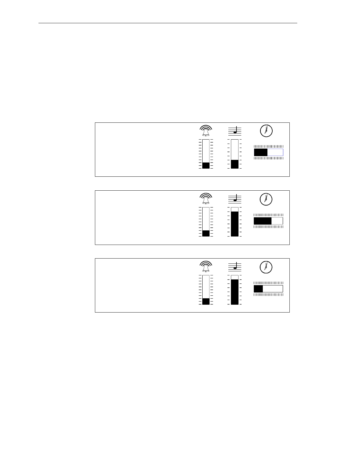
Chapter 7: Programming 7-73
Good Read Tone Presets
The Good Read tone is composed of three elements: volume, frequency
(tone), and length. Three different presets, each with a different
combination of volume, tone, and tone length settings, are available
that permit you to set the Good Read tone by scanning just one
sequence of Programming Tags. Preset 0 is the default for this
parameter.
16086
Preset 0
Volume Tone Length
12
3
4
5
6
7
8
9
10
11 12
Preset 1
Volume Tone Length
12
3
4
5
6
7
8
9
10
11 12
Preset 2
Volume Tone Length
12
3
4
5
6
7
8
9
10
11 12
Programming Mode
Hex 4
Hex 3
Hex 0
Save and Reset
Programming Mode
Hex 4
Hex 3
Hex 1
Save and Reset
Programming Mode
Hex 4
Hex 3
Hex 2
Save and Reset

7-74 Chapter 7: Programming
Good Weigh Tone When Transmitting Data
A Good Weigh tone normally sounds when an item is weighed. If the
Good Weigh Tone When Transmitting Data option is enabled the Good
Weigh tone sounds when the weight data is just starting to be
transmitted to the host terminal when using single cable RS-232
communications. The Default tag disables this option. Scan the
following programming tags to enable or disable this option. These
must be the first tags scanned after applying power to the NCR 7870.
Enable – Programming Mode, Hex 2, Hex 4, Hex 9, and Save and
Reset.
Disable – Programming Mode, Hex 2, Hex 4, Hex 8, and Save and
Reset.

Chapter 7: Programming 7-75
Terminal Coupon Interface Parameters
Certain parameters must be set to permit the unit to transmit coupon
data to the host terminal. These are in addition to the general
parameters that are required for other scanner/scale functions.
Note: Selection of optional add-on bar codes may require additional
programming. See Early Beep Disable in the Special Programming
section for more information.
The first part of setting the Coupon Interface Parameters is
Programming Multi-Symbol Scanning.
1. Scan the Programming Mode tag.
2. Scan the Hex 3 and Hex 8 tags to select this parameter.
3. Scan a Hex 0 through Hex F tag to set a Coupon Select 1 parameter.
Coupon Select 1 Parameter Disable Enable
Coupon with P5 optional Hex 0 Hex 1
Coupon with 128 add-on optional Hex 2 Hex 3
Coupon with 128 add-on mandatory Hex 4 Hex 5
Markdown with 128 add-on optional Hex 6 Hex 7
Program 1 with 128 add-on optional Hex 8 Hex 9
Program 1 with 128 add-on mandatory Hex A Hex B
Program 2 with 128 add-on optional Hex C Hex D
Program 2 with 128 add-on mandatory Hex E Hex F
4. Scan the Save and Reset tag to save the program (required).

7-76 Chapter 7: Programming
5. Repeat steps 1 through 4 to set the second Coupon Select 1
parameter.
Suggested Programming Sequence
• Programming Mode
• Hex 3 and Hex 8
• Hex 1
• Save and Reset
• Programming Mode
• Hex 3 and Hex 8
• Hex 3
Note: Scanning the Default tag disables all options.
The second part is to Set Terminal Coupon Select 2 Parameter.
1. Scan the Programming Mode tag.
2. Scan the Hex 3 and Hex D tags to select this parameter.
3. Scan a Hex 0 through Hex 7 tag to set a Coupon Select 2 parameter.
Coupon Select 2 Parameter Disable Enable
Coupon & P5 or 128 optional (EAN-99) Hex 0 Hex 1
Coupon &128 mandatory (EAN-99) Hex 2 Hex 3
Markdown Tone Hex 4 Hex 5
Early Tone for Optional Add-On Hex 6 Hex 7
4. Scan the Save and Reset tag to save the program.
5. Repeat steps 1 through 4 to set the other option, if needed.
Note: Scanning the Default tag disables all options.
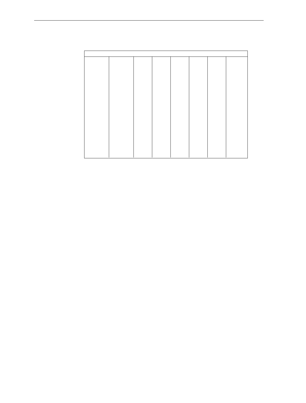
Chapter 7: Programming 7-77
ASCII Code Chart
70
71
72
73
74
75
76
77
78
79
7A
7B
7C
7D
7E
7F
p
q
r
s
t
u
v
w
x
y
z
{
|
}
DEL
60
61
62
63
64
65
66
67
68
69
6A
6B
6C
6D
6E
6F
a
b
c
d
e
f
g
h
i
j
k
l
m
n
o
50
51
52
53
54
55
56
57
58
59
5A
5B
5C
5D
5E
5F
P
Q
R
S
T
U
V
W
X
Y
Z
[
\
]
^
_
40
41
42
43
44
45
46
47
48
49
4A
4B
4C
4D
4E
4F
@
A
B
C
D
E
F
G
H
I
J
K
L
M
N
O
30
31
32
33
34
35
36
37
38
39
3A
3B
3C
3D
3E
3F
0
1
2
3
4
6
5
7
8
9
:
;
<
=
>
?
20
21
22
23
24
25
26
27
28
29
2A
2B
2C
2D
2E
2F
SP
!
"
#
$
%
&
'
(
)
*
+
,
-
.
/
10
11
12
13
14
15
16
17
18
19
1A
1B
1C
1D
1E
1F
DLE
DC1
DC2
DC3
DC4
NAK
SYN
ETB
CAN
EM
SUB
ESC
FS
GS
RS
US
00
01
02
03
04
05
06
07
08
09
0A
0B
0C
0D
0E
0F
NULL
SOH
STX
ETX
EOT
ENQ
ACK
BEL
BS
HT
LF
VT
FF
CR
S0
S1
ASCII Code Chart
R0040

7-78 Chapter 7: Programming

Chapter 8: Troubleshooting
This chapter discusses the troubleshooting a user may perform to
diagnose problems which may occur during use of the NCR 7870. For
more comprehensive repair and service information, refer to the NCR
7870 Scanner/Scale Repair Guide (D2-0966-A).
Fault Identification
The NCR 7870 Scanner/Scale performs internal diagnostic checks upon
various functions during operation and the power-up sequence.
Scanner operational problems are signaled by
• a series of tones,
• Voice Messages (if available), and
• Status Indicator light flashing.
Scale operational problems are signaled by an error code displayed on
the NCR 7825 Remote Display or the integrated display. Like the
scanner, the scale unit performs diagnostic checks during the power-up
sequence and while in operation.
Troubleshooting consists of troubleshooting charts that are designed
for locating and correcting certain problems without the aid of a
trained technician. If the problem cannot be corrected by using these
charts, a trained technician can then use the on-board diagnostics to
help identify a faulty component.

8-2 Chapter 8: Troubleshooting
Scanner Troubleshooting Chart
Problem Status Indicator Tone Possible Cause Corrective Action
Scanner
does not
operate
Red Off
Green Off Off No power Check outlet for proper
power
Scanner
does not
operate
Red Flashing
Green Flashing Off Sleep mode Pass anything in front of
Motion Detector
Scanner
does not
operate
Red Flashing Off Communication
is IBM 468x and
scanner is off-
line
Host terminal
has sent a
“disable
scanner”
command
1. Verify the IBM terminal
is off.
2. Verify the IBM terminal
is recognizing the 7870.
3. Verify the Interface
Cable is properly
connected.
Scanner
does not
read tags
Red On Off Internal failure 1. Turn off circuit breaker
to the 7870 then turn
back on.
2. If problem remains,
have the 7870 repaired.
Scanner
reads only
two tags
Red On Off 7870 is not
communicating
with host
terminal
1. Check host terminal for
proper operation.
2. Verify the Interface
Cable is properly
connected.

Chapter 8: Troubleshooting 8-3
Scale Troubleshooting Chart
Note: This information does not apply to the NCR 7870-4000 which
uses a Bizerba scale. For information on troubleshooting or servicing
an NCR 7870-4000 scale unit, refer to the Bizerba documentation or
contact the Bizerba representative.
Problem Possible Cause Corrective Action
Error code 5 - - - -
displays Scale drift 1. Verify nothing is on scale.
2. Lift Top Plate and verify no
objects are under it.
3. Push Reset/Scale Zero button.
4. Power down/up unit.
5. If error code persists, have unit
repaired.
Error code 4 - - - -
displays Possible scale error 1. Press Scale Zero button and retry.
2. If error code persists, have unit
repaired.
Error code 4 - - - -
displays during
calibration
Slight vibration to scale
during calibration Calibrate scale. Ensure there is no
external scale movement while
weights are on scale.
Scale display is
blank Top Plate prevented
from moving down 1. Remove any interference around
edge of Top Plate and
checkstand.
2. Remove any foreign objects from
under Top Plate.
3. Push Reset/Scale Zero button.
Intermittent error
codes +12 VDC is unstable Have 7870 repaired.

Chapter 8: Troubleshooting 8-5
Voice Messages Troubleshooting Chart
Problem Possible Cause Corrective Action
No Voice
Messages Firmware does not have
voice capability. Check firmware on the Digital Board.
• Power unit OFF and then ON.
• Scan the Diagnostic Mode tag.
• Scan Hex 4 and Hex A tags.
Firmware version should appear in
display. Version must be 497-0301951 or
higher to have Voice Messaging feature.
Voice Messages option
turned off. Toggle Voice Messages Option.
• Power unit OFF and then ON.
• Scan Programming Mode tag.
• Scan Hex 3, Hex 2, and Hex D tags.
This will turn option on if it were off.

8-6 Chapter 8: Troubleshooting

Appendix A: Programming Worksheets
General
The programming worksheets provide a convenient method of
defining your NCR 7870 program before loading it into the unit. Each
worksheet relates to a Specific Programming Mode.
Purpose The programming worksheets permit you to determine the exact
sequence of tags to scan for each programming parameter. It also
provides you with a hard copy of the program for possible future use.
Format The top half of each worksheet identifies the programming parameters
and the specific tags for each one. Most of the worksheets contain
arrows that guide you through the proper sequence. The bottom half
of each worksheet provides a place for you to write in each of your
selections.
Shortcuts Most of the worksheets contain shortcuts that permit you to enter
specific parameters without entering the entire worksheet. These
parameters have an alpha character in a box just left of the parameter
name. Scanning the Hex tag that corresponds to the alpha character
enables input for that parameter. You then scan the tags that pertain to
that parameter. After entering the specified parameter, the program
returns to the Base Programming State.

A-2 Appendix A: Programming Worksheets
Defaults Most of the programming parameters have defaults that are
determined at the factory. A heavy box around an entry specifies it as
a default value. Scanning the Default tag as the first tag after applying
power to the 7870 sets the parameters to these values.
Hex CharactersSome of the programming parameters require Hex characters. Refer to
the ASCII Code Chart for the proper selections.
Program Entry Some host terminals can corrupt your program if they are running and
are connected to the 7870 while a program is being entered. Either turn
the host terminal off or disconnect all interface cables to the 7870 before
entering the program.
1. Enter the Base Programming state by scanning the Programming
Mode tag. This must be the first tag scanned after powering up the
7870.
2. Select a Programming Worksheet and enter its parameter data by
scanning the Hex tags identified in Your Program at the bottom of
the Programming Worksheet. Repeat this for each Worksheet.
3. Save the program by scanning the Save and Reset tag.

Appendix A: Programming Worksheets A-3
Programming Parameter Defaults
Programming Mode Default
Communications Protocol
Protocol No Default
Good Read Tone
Tone On/Off
Tone Frequency
Tone Length
Tone Volume
Not-on-File Tone Volume
On
No Default
No Default
No Default
No Default
Timers
Lockout Time
Restart Lockout Timer
Active Time
900 milliseconds
Off
15 seconds
Bar Codes-1
UPC/EAN
Version D
Extend UPC-A to EAN-13
Extend UPC-E to UPC-A
Periodic Codes
Periodic Codes Extension
Send Data
Enable
None
Disable
Disable
Disable
2-Digit & 5-Digit
Data as Decoded
Bar Codes-2
Code 39
Min. Characters Allowed
Full ASCII
Check Digit Present
Transmit Check Digit
Allow 1-or-2 Character Tag
Disable
8
Disable
Disable
Disable
Disable

A-4 Appendix A: Programming Worksheets
Programming Mode Default
Bar Codes-3
Interleaved 2 of 5
Bar Code Length
Value 1
Value 2
Check Digit Present
Transmit Check Digit
Disable
Range Check
04
16
Disable
Disable
Bar Codes-4
Code 128
Min. Data Characters Allowed
UCC 128
Disable
3
Disable
Label Identifiers
Identifier Type
Common Byte 1
Common Byte 2
Bar Code Type
Common Byte
Unique Identifier
Version Number (UPC-D)
Default Prefix
5D
42
No Default
See Chapter 7
See Chapter 7
Not Included
RS-232 Parameters-1
Baud Rate
Parity
Stop Bits and Character Length
Handshake
9600
Odd
1 Stop Bit, 7-Bit Character
RTS High, Wait for CTS
RS-232 Parameters-2
BCC Options
Interface Control
Check Digit
Scale Only – Disable
Scanner/Scale – Enable
None
Enable UPC-A
Enable EAN-8
Enable EAN-13
Disable UPC-E

Appendix A: Programming Worksheets A-5
Programming Mode Default
RS-232 Prefix Byte
Prefix Byte
ASCII Code Disable
02
RS-232 Terminator Byte
Terminator Byte
ASCII Code Disable
03
RS-232 Communications Options
Message Delay
Scanner or Scanner/Scale Format
Normal or Eavesdrop Mode
Beep at Scale Weight Transmission
10 ms Delay
Determined by Model
Normal Mode
No Beep
Scale Parameters
Model Number
9.995 kg/13.995 kg
IBM Address
No Default
No Default
Address 6E set by
selecting IBM 468x on
Communications Protocol
Worksheet
Miscellaneous Parameters
5-Second Weight Display Timer
IBM Tone Control (Good Read Tone)
OCIA Price Display
IBM Rexmit Control
OCIA Blank Display in Price Mode
Enable/Disable Voice Messages
IBM Tag Data Format
Enabled
Enabled
Enabled
Permanently Enabled
Disabled
No Default
Hex
Dual Cable Interface
Scale Type Avery
A-6 Appendix A: Programming Worksheets
Worksheets
COMMUNICATIONS PROTOCOL
01
1 0
Communications
Protocol
Protocol
Your Program
14391
OCIA
NCR Long
IBM
Slot Scanner
OCIA
Non NCR
Dual Cable
OCIA
Single Cable
RS-232
Casio
Dual Cable
OCIA NCR
Dual Cable
IBM
Hand-Held
Bar Code
Reader
0
OCIA
NCR Short
(Datachecker)
IBM 1520
Bar Code
Reader
TEC
Dual Cable
1 2 3 5
6 7 A B
4
C
Appendix A: Programming Worksheets A-7
Your Program
Tone
On/Off
A
Frequency
Tone
B
Tone
Length
C
Tone
Volume
D
11BCD
***
Not-On-File
Tone
Volume
E
E*
* Scan Hex tag repeatedly for desired setting.
Good Read Tone
B053
A
B
C
D
E
0 1
Off On
Tone On/Off
Tone Frequency
(Hertz)
BWhen entering Tone Frequency, the adjustment can be
incremented upward by scanning the Hex B tag. Each
time you scan the Hex B tag, the tone frequency
increases one unit. Scan the End tag or a valid Hex tag
to end this mode.
Tone Length
(Milliseconds)
CWhen entering Tone Length, the adjustment can be
incremented upward by scanning the Hex C tag. Each
time you scan the Hex C tag, the tone length increases
one unit. Scan the End tag or a valid Hex tag to end
this mode.
Tone Volume DWhen entering Tone Volume, the adjustment can be
incremented upward by scanning the Hex D tag. Each
time you scan the Hex D tag, the tone Volume increases
one unit. Scan the End tag or a valid Hex tag to end
this mode.
Not-On-File
Tone Volume
EWhen entering Not-On-File Tone Volume, the adjustment
can be incremented upward by scanning the Hex E tag.
Each time you scan the Hex E tag, the tone Volume
increases one unit. Scan the End tag or a valid Hex tag
to end this mode.
GOOD READ TONE
11
A-8 Appendix A: Programming Worksheets
A
B
C
Lockout Time
(Milliseconds) 01234 675
450 600 750 900 1050 1200 1350 1500
Restart
Lockout Timer 0 1
Off On
Active Time
(Minutes) 0123
0 153060
No Time-out ( Always Active)
Note: NCR suggests that you do not set the Active Time
parameter to 0. Leaving the laser light on all the time reduces
its life expectancy.
12
TIMERS
12
Your Program
Timers Lockout
Time
R0136
A
Restart
Lockout
Timer
B
Active
Time
C
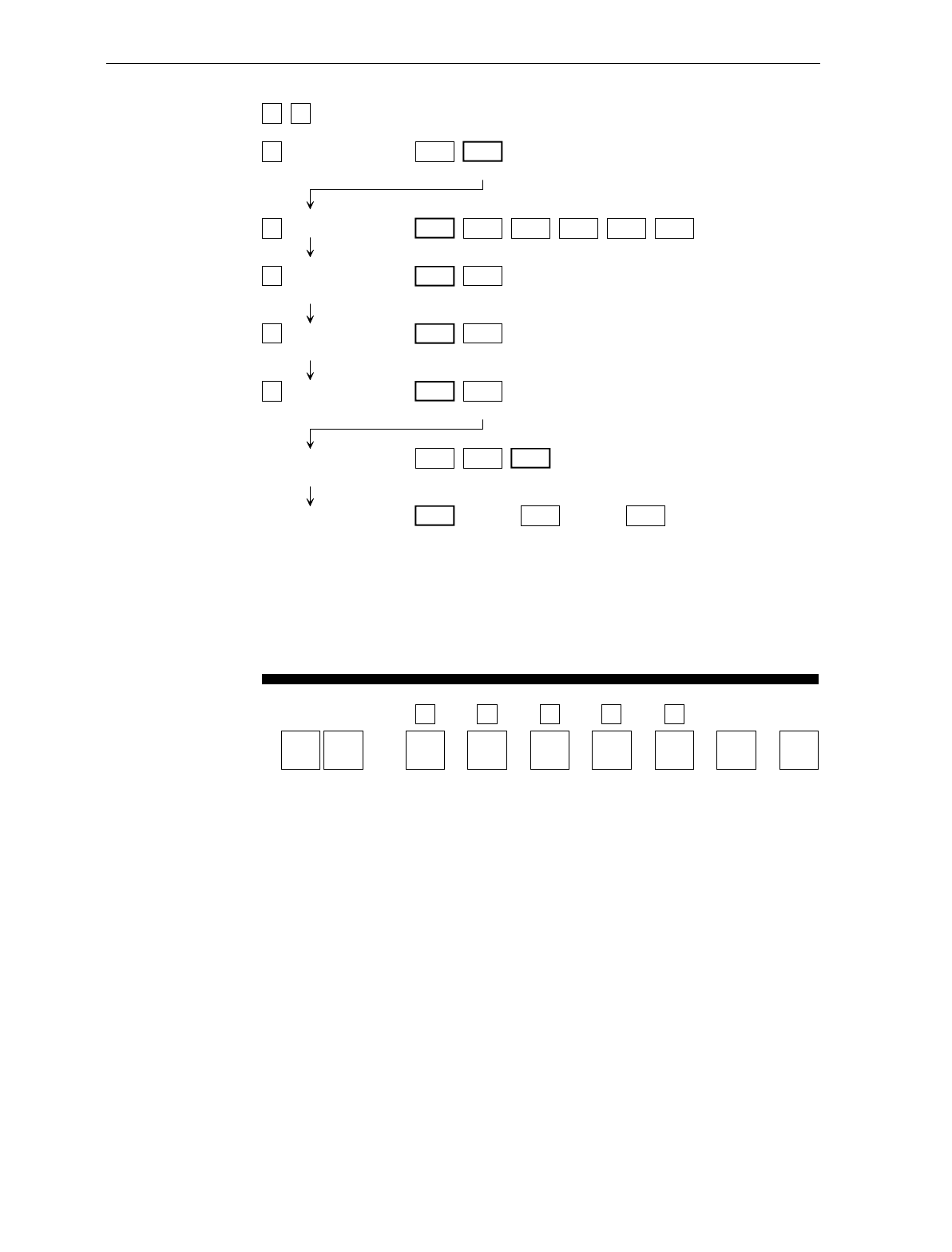
Appendix A: Programming Worksheets A-9
A
B
C
D
E
UPC/EAN 0 1
Disable Enable
Version D 0 1
None D-1
2 3
D-2 D-3
4 5
D-4 D-5
Extend UPC-A
To EAN-13
0 1
Disable Enable
Extend UPC-E
To UPC-A
0 1
Disable Enable
Periodical Codes 0 1
Disable Enable
Periodical Code
Extension
0 1
2-Digit
Only 5-Digit
Only
2
2-Digit &
5-Digit
Send Data 0 1
Data As
Decoded Periodical Code
Data Only
2
2CF Hex
If Periodical Data
Not Decoded
13
BAR CODES - 1
13
Your Program
Bar Codes - 1 UPC/
EAN
14393
A
Version
D
B
Extend
UPC-A
C
Extend
UPC-E
D
Periodical
Codes
E
Periodical
Code
Extension
Send
Data
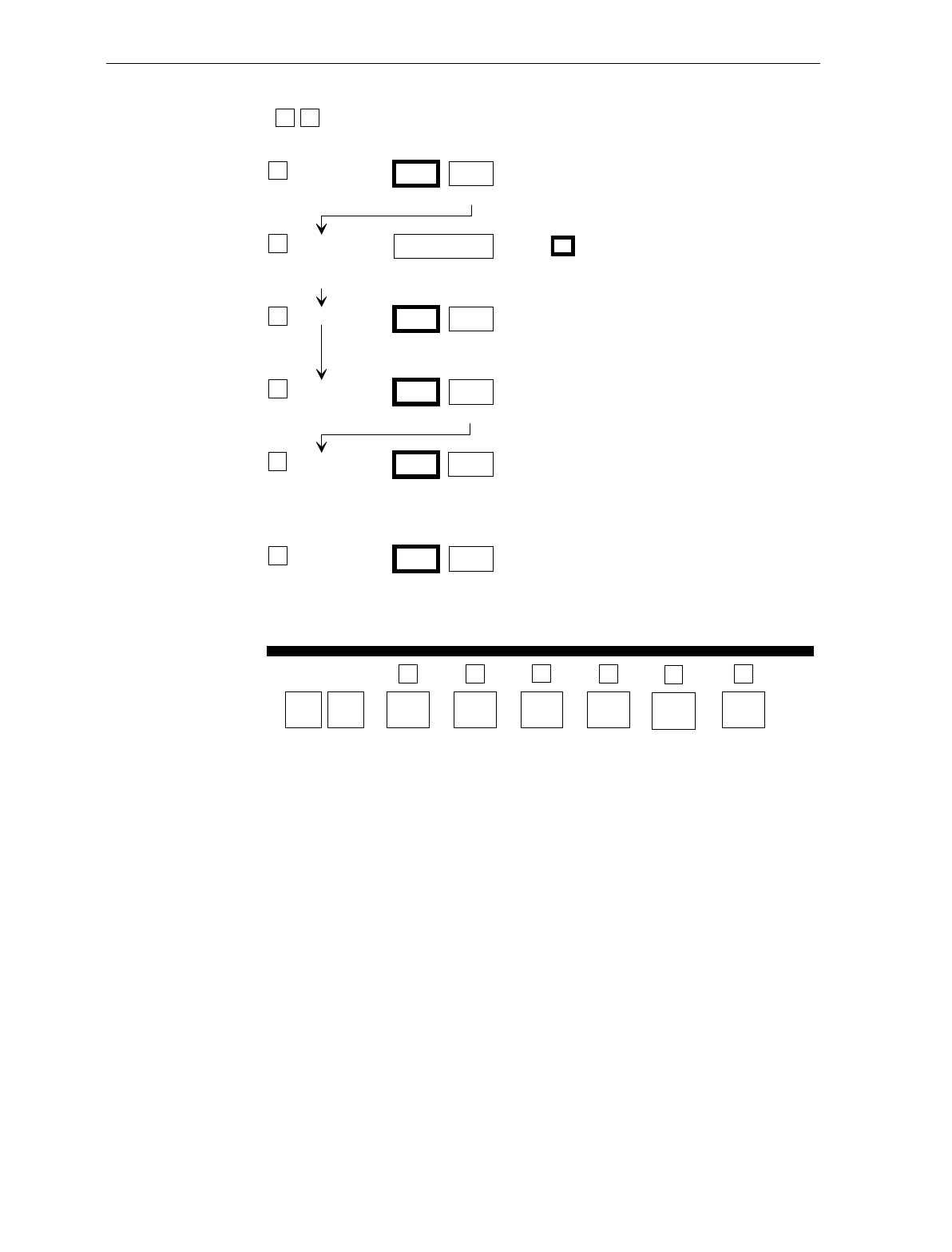
A-10 Appendix A: Programming Worksheets
BAR CODES - 2
1 4
ACode 39
Disable
0
Enable
1
Minimum
Characters
Allowed
B
Full ASCII
C
Disable
0
Check Digit
Present
D
Enable
1
Disable
0
Transmit
Check Digit
E
Enable
1
Disable
0
Enable
2 - F
1
Default: 8
Enable
1
Disable
0
FAllow Single
Character
Tags
Your Program A
Code 39
Bar Codes - 2
1 4
Full ASCII
C
Minimum
Characters
Allowed
B
Transmit
Check Digit
E
Check Digit
Present
D F
Allow
Single
Character
Tags
14394
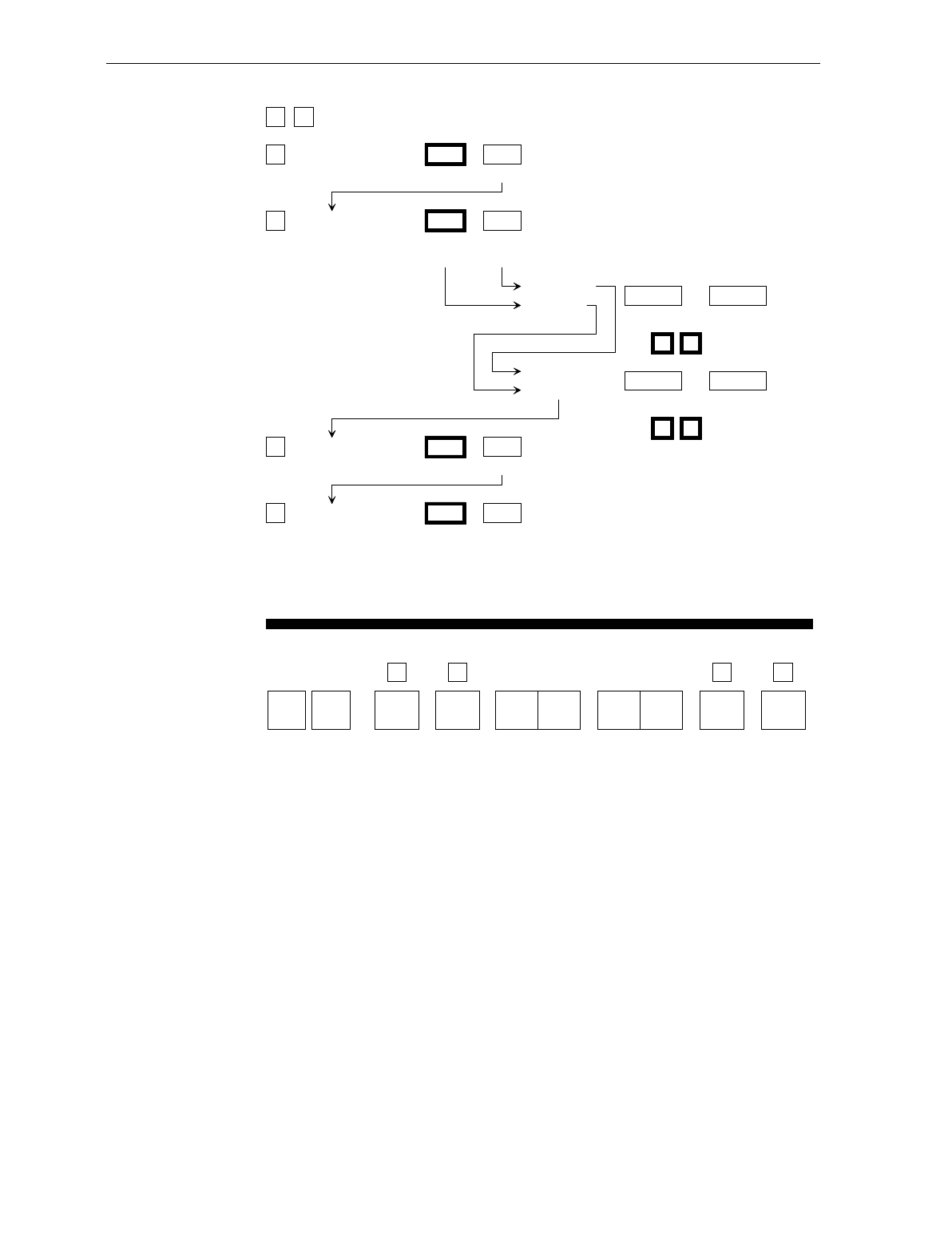
Appendix A: Programming Worksheets A-11
1 5 BAR CODES - 3
A
B
C
D
Interleaved 2 of 5 0 1
Disable Enable
Bar Code Length 0 1
Range
Check
Specific
Check
Value 1 Characters
Minimum 0 - 3 0 - 9
Character 1 Character 2
0 8 Default
Value 2 Characters
Minimum 0 - 3 0 - 9
Character 1 Character 2
1 6 Default
Check Digit Present 0 1
Disable Enable
Transmit Check Digit 0 1
Disable Enable
Your Program
A
Interleaved
2 of 5
Bar Codes - 3
1 5
Check
Digit
Present
C
Transmit
Check
Digit
D
Value 1 Value 2Bar
Code
Length
B
B049
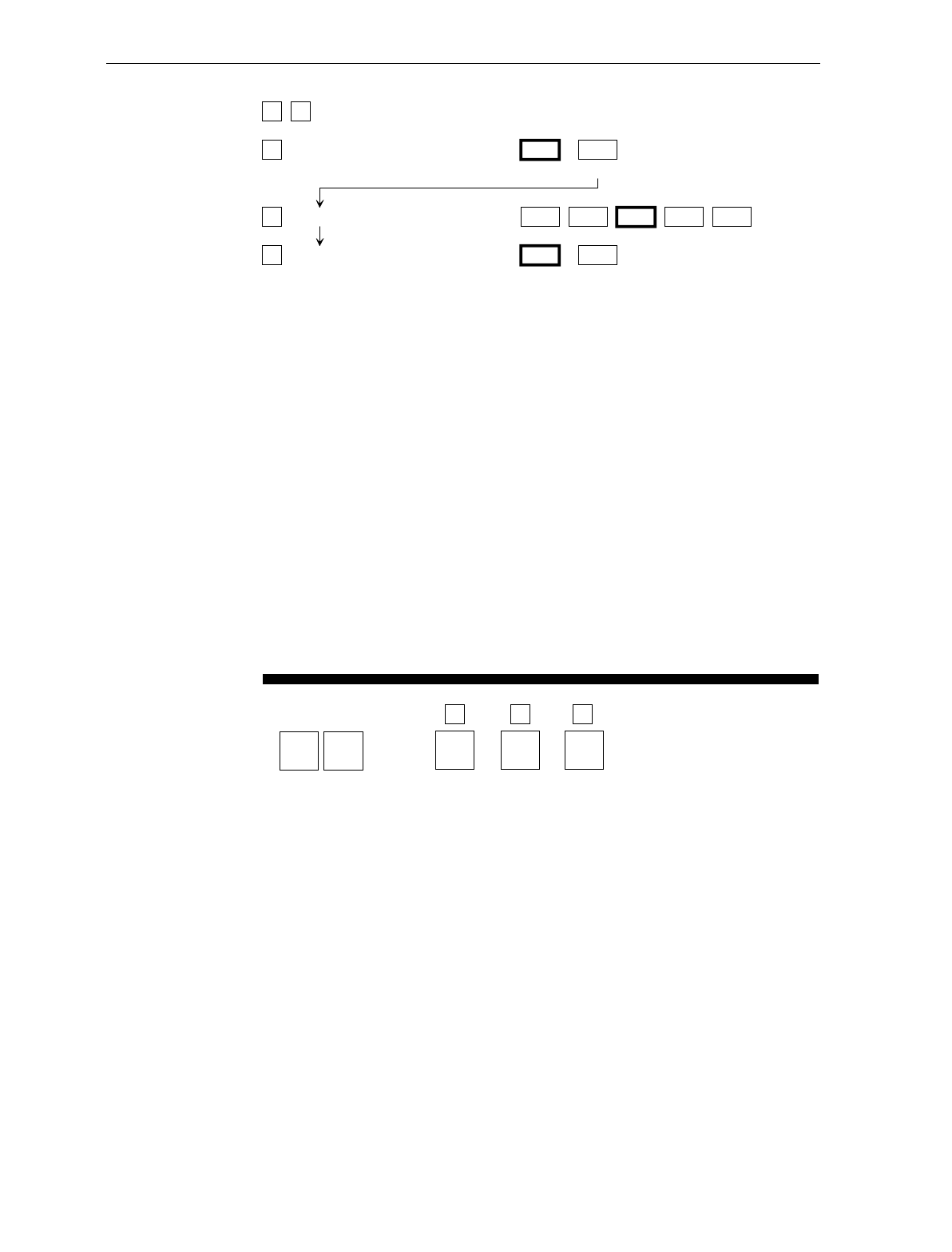
A-12 Appendix A: Programming Worksheets
1 7 BAR CODES - 4
A
B
C
Code 128 0 1
Disable Enable
Minimum Data Characters Allowed 12345
UCC 128 0 1
Disable Enable
Your Program A B
1 7
Code
128
Minimum
Data
Characters
Allowed
UCC
128
C
Bar Codes - 4
B050
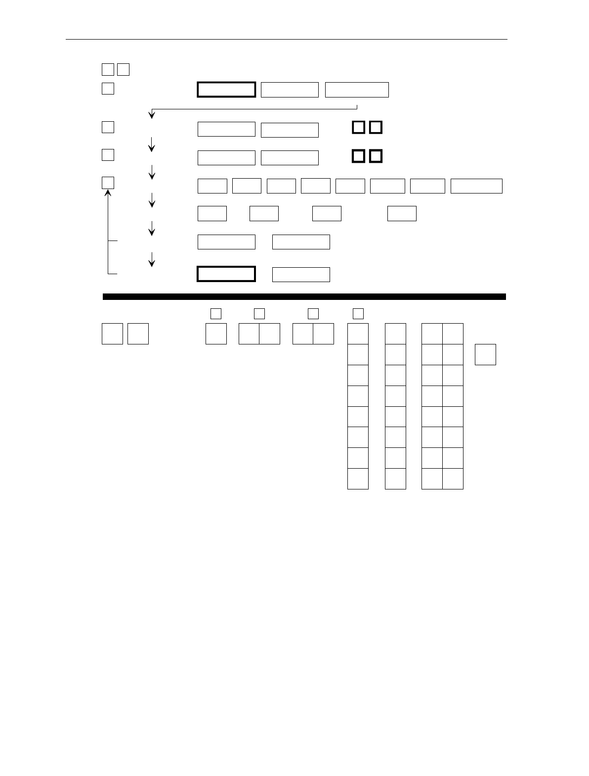
Appendix A: Programming Worksheets A-13
Include
NOTE: Scan the End tag to end the
Label Identifier Programming mode.
Your Program B
Common
Byte 1
C
Common
Byte 2
D
Bar Code
Type Common
Byte
Version
Number
Label
Identifier
1 6
A
Identifier Type
Unique
Identifier R0143
Common Byte
None
0
Common Byte 1
1
Common Byte 2
2
Both Common Bytes
3
LABEL IDENTIFIERS
1 6
DBar Code Type 0
UPC-A
1
UPC-D
2
UPC-E
3
EAN-8
4
EAN-13
5
Code 39
6
Code 128 Interleaved
2 of 5
7
Unique Identifier Default: Varies according to Bar Code Type.
0-7
Hex Character 0-F
Hex Character
AIdentifier Type Default Prefix
0
BCommon Byte 1 Default: 5 D
CCommon Byte 2 0-7
Hex Character
0-F
Hex Character
Default: 4 2
Version Number 1
0
None Unique Prefix
2 3
0-F
Hex Character
Hex Character
0-7
Do Not Include
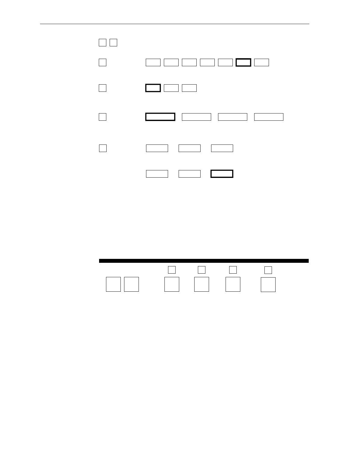
A-14 Appendix A: Programming Worksheets
Your Program
02
RS-232
Parameters - 1
B
Parity
D
Handshake
A
Baud
Rate
Stop Bits And
Character Length
C
2 0 RS-232 PARAMETERS - 1
A
B
C
D
Baud Rate 0
300
1
600
2
1200
3
2400
4
4800
5
9600
6
19200
Parity 0
Odd
1
Even
4
None
Stop Bits And
Character
Length
0
1 Stop Bit
7-Bit Character
1
1 Stop Bit
8-Bit Character
2
2 Stop Bits
7-Bit Character
3
2 Stop Bits
8-Bit Character
Handshake 0
RTS Low
CTS Ignored
1
RTS High
CTS Ignored
2
Raise RTS
Wait for CTS
Raise RTS
Ignore CTS RTS Low
Wait for CTS
345
RTS High
Wait for CTS
11809
Note: On a 7870-2000, 4000, or 4500,
Parity must be Odd or Even. If
None is selected, Odd is used.
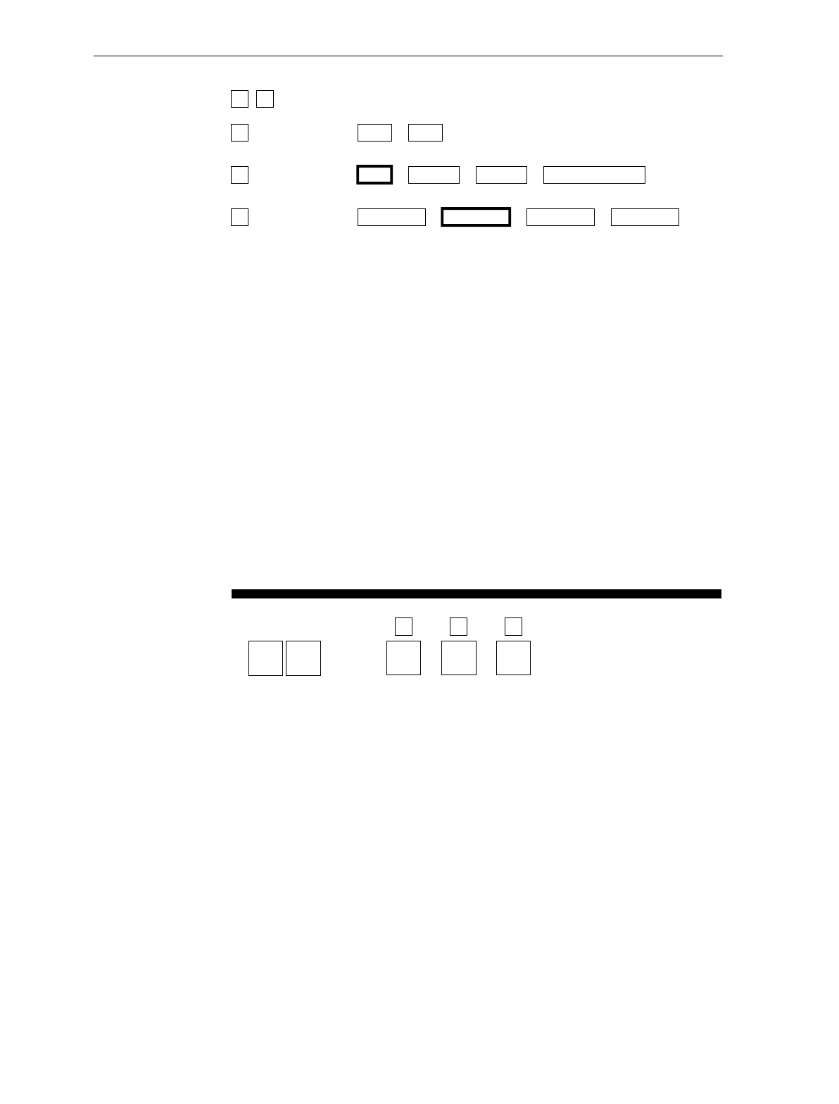
Appendix A: Programming Worksheets A-15
2 1 RS-232 PARAMETERS - 2
A
B
C
BCC Options 0
Disable
1
Enable
Default: 7870-1000, 3000 - Disable
7870-2000, 4000, 4500 - Enable
Interface Control 0
None
1
ACK/NAK
2
XOn/XOff
3
ACK/NAK & XOn/XOff
Check Digit 0
Disable UPC-A
Disable EAN-8
Disable EAN-13
Disable UPC-E
1
Enable UPC-A
Enable EAN-8
Enable EAN-13
Disable UPC-E
2
Disable UPC-A
Disable EAN-8
Disable EAN-13
Enable UPC-E
3
Enable UPC-A
Enable EAN-8
Enable EAN-13
Enable UPC-E
Note: Check Digit parameter also applies to UPC-E
when using for OCIA communications.
21
Your Program
RS-232
Parameters - 2 BCC
Options
11810
A
Interface
Control
B
Check
Digit
C
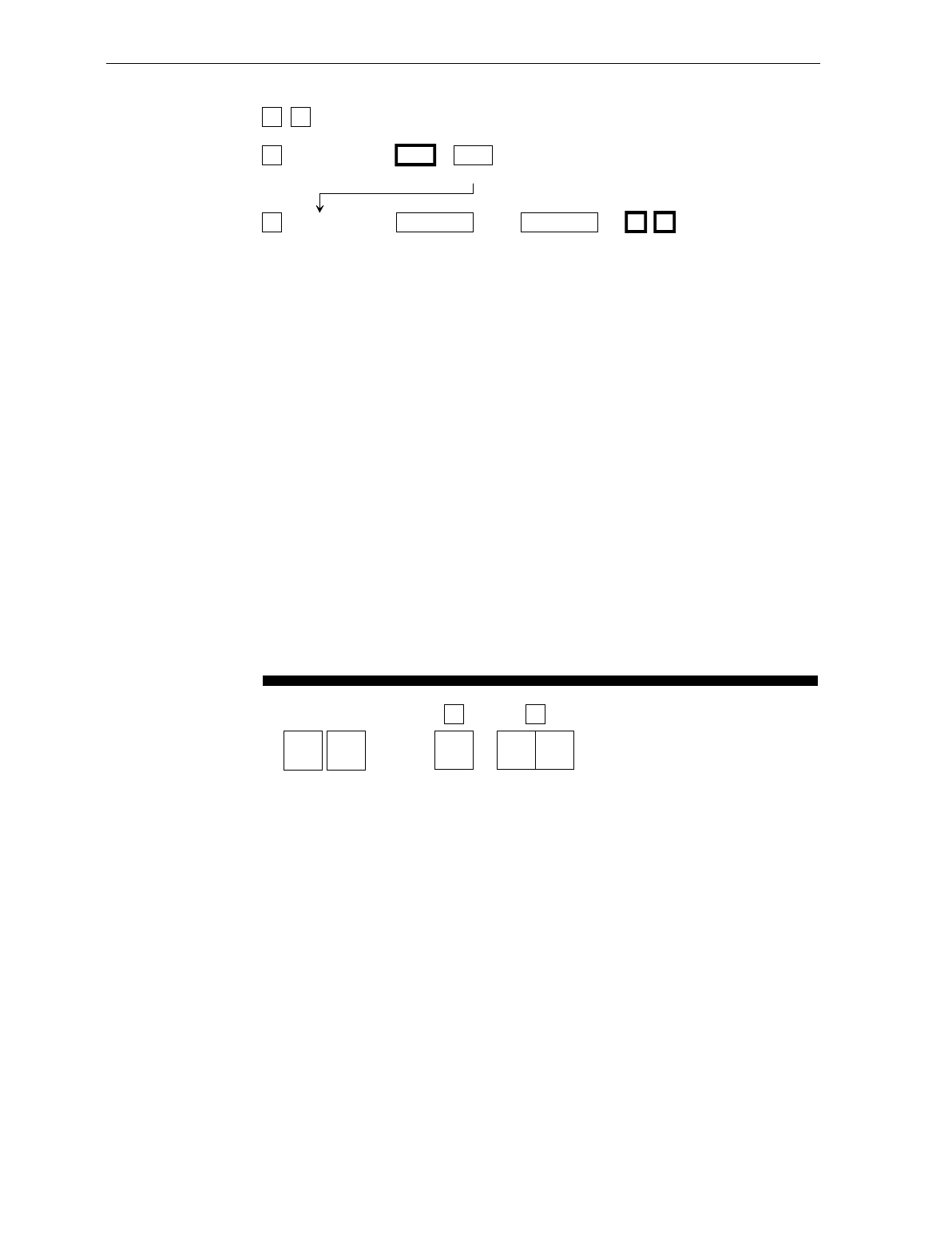
A-16 Appendix A: Programming Worksheets
2 2 RS-232 PREFIX BYTE
A
B
Prefix Byte 0
Disable
1
Enable
ASCII Code 0 - 7
Hex Character
(ASCII Code Chart)
0 - F
Hex Character
(ASCII Code Chart)
0 2 Default
22
Your Program
RS-232
Prefix Byte Prefix Byte
A
ASCII
Code
B
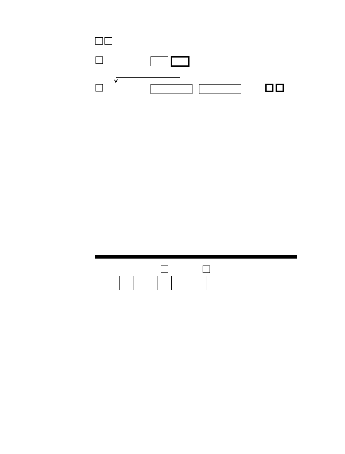
Appendix A: Programming Worksheets A-17
RS-232 TERMINATOR BYTE
2 3
ATerminator
Byte Disable
0
Enable
1
BASCII Code 0-7
(ASCII Code Chart)
Hex Character
0-F
(ASCII Code Chart)
Hex Character
Default: 0 3
Your Program A
Terminator Byte
B
Code
ASCII
RS-232
Terminator Byte
2 3
NOTE: On a 7870 scale unit, a Terminator Byte is required.
If you select Disable, it is ignored and an ETX (03) is sent.
R0148
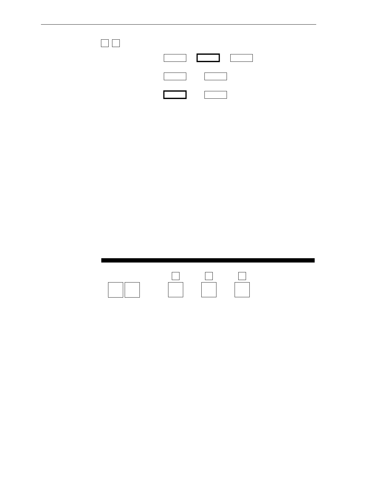
A-18 Appendix A: Programming Worksheets
2 4 RS-232 COMMUNICATIONS OPTIONS
Message Delay 0
No Delay
1
10ms Delay
2
50ms Delay
Scanner or
Scanner/Scale Format
4
Scanner Only
5
Scanner/Scale
Normal or
Eavesdrop Mode 6
Normal Mode
7
Eavesdrop Mode
24
Your Program
RS-232
Communications
Options
Message
Delay
12163
A
Scanner or
Scanner/Scale
Format
B
Normal or
Eavesdrop
Mode
C
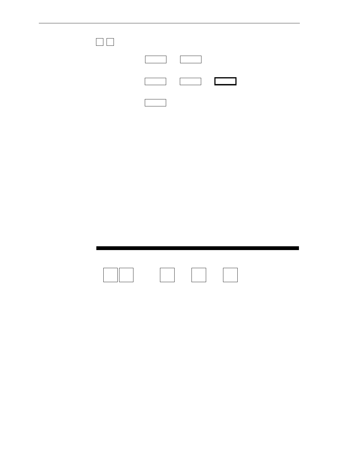
Appendix A: Programming Worksheets A-19
30
Your Program
Scale
Parameters
11812
Model
Number IBM
Address 10 kg /
13.995 kg
3 0 SCALE PARAMETERS
Model Number 3
Scanner/Scale
4
Scanner Only
IBM Address 5
Address 6A
6
Address 6B
7
Address 6E
10 kg / 13.995 kg
Toggle Between
10 kg and
13.995 kg
B
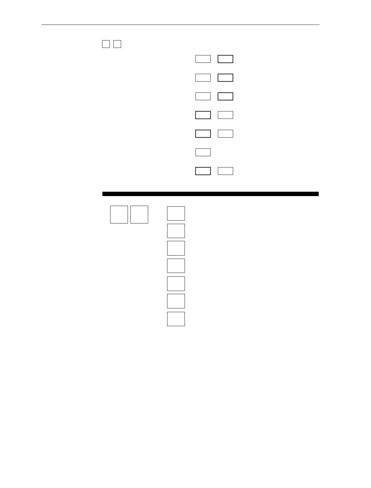
A-20 Appendix A: Programming Worksheets
3 2 MISCELLANEOUS PARAMETERS
5-Second Weight Display Timer 1
Disable
2
Enable
IBM Tone Control
(Good Read Tone Control) 3
Disable
4
Enable
5
Disable
6
Enable
OCIA Price Display
IBM Rexmit Control 7
3 Times
8
Forever
OCIA Blank Display in Price Mode 9
Disable
A
Enable
Enable/Disable Voice Messages D
Toggle
Default: Enabled
IBM Tag Data Format E
Hex
F
ASCII
Miscellaneous
Parameters
325-Second Weight Display Timer
IBM Tone Control
OCIA Price Display
IBM Rexmit Control
OCIA Blank Display in Price Mode
Toggle Enable/Disable of Voice Messages
IBM Tag Data Format 11823
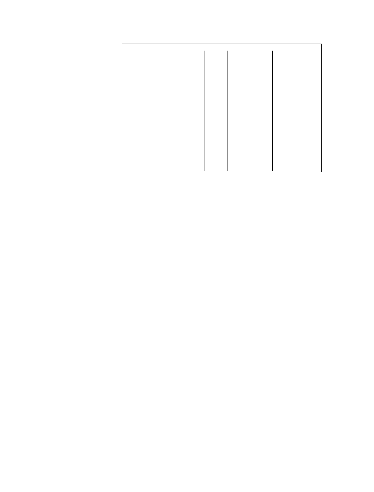
Appendix A: Programming Worksheets A-21
70
71
72
73
74
75
76
77
78
79
7A
7B
7C
7D
7E
7F
p
q
r
s
t
u
v
w
x
y
z
{
|
}
DEL
60
61
62
63
64
65
66
67
68
69
6A
6B
6C
6D
6E
6F
a
b
c
d
e
f
g
h
i
j
k
l
m
n
o
50
51
52
53
54
55
56
57
58
59
5A
5B
5C
5D
5E
5F
P
Q
R
S
T
U
V
W
X
Y
Z
[
\
]
^
_
40
41
42
43
44
45
46
47
48
49
4A
4B
4C
4D
4E
4F
@
A
B
C
D
E
F
G
H
I
J
K
L
M
N
O
30
31
32
33
34
35
36
37
38
39
3A
3B
3C
3D
3E
3F
0
1
2
3
4
6
5
7
8
9
:
;
<
=
>
?
20
21
22
23
24
25
26
27
28
29
2A
2B
2C
2D
2E
2F
SP
!
"
#
$
%
&
'
(
)
*
+
,
-
.
/
10
11
12
13
14
15
16
17
18
19
1A
1B
1C
1D
1E
1F
DLE
DC1
DC2
DC3
DC4
NAK
SYN
ETB
CAN
EM
SUB
ESC
FS
GS
RS
US
00
01
02
03
04
05
06
07
08
09
0A
0B
0C
0D
0E
0F
NULL
SOH
STX
ETX
EOT
ENQ
ACK
BEL
BS
HT
LF
VT
FF
CR
S0
S1
ASCII Code Chart
R0040

A-22 Appendix A: Programming Worksheets

Index
—A—
Abort Tag, 7-6
Accessing Calibration Switch, 5-4–5-6
ASCII Code Chart, 7-77
Auto-Zero, 2-11
—B—
Bar Codes
Quality, 6-6
Recognition, 2-1
Bar Codes - 1 Parameters, 7-22–7-24
Bar Codes - 2 Parameters, 7-25–7-27
Bar Codes - 3 Parameters, 7-28–7-30
Bar Codes - 4 Parameters, 7-31–7-32
Bi-Optic Scanning, 2-2
—C—
C E Mark Applicability, xii
Cables, 3-21–3-26
AC Power, 3-22
DC Power, 3-21
Hole Diameters, 3-21
Interface, Casio, 3-25
Interface, Data Checker, 3-26
Interface, Epson, 3-26
Interface, Gilbarco, 3-26
Interface, IBM, 3-27
Interface, ICL, 3-27
Interface, Microbilt, 3-28
Interface, NCR, 3-23–3-25
Interface, NEC, 3-28
Interface, SASI, 3-29
Remote Display, 3-22
Calibration
Displaying audit trail, 5-2
General, 5-1
Procedures
Accessing the Calibration Switch, 5-4
Connecting the Field Service Calibration
Display, 5-7
Exercising the Scale, 5-3
Performing the Calibration, 5-9
Securing the Calibration Switch, 5-16
Verifying, 5-11–5-15
Weight Sets, 5-2
When to perform, 5-1
Which models, 5-1
Checkstand
Considerations, 3-15
Display Clearance, 3-17
Item Diverter, 3-17
Service Clearance, 3-16
Ventilation, 3-15
Hole (Cutout, Bucket), 3-18
Dimensions (Models 1000 & 2000), 3-19
Dimensions (Models 3000, 4000, 4500), 3-20
Power Requirements, 3-9
Wiring Considerations, 3-2, 3-10
Europe, 3-11
Instructions, 3-13
International, 3-12
U.S., Canada, Japan, 3-10
Communications Protocol Parameters, 7-
13–7-17

Index-2
—D—
Declaration of Conformity, xiii
Decode Features, 2-2
Default Tag, 7-7
Diagnostics
Determining Communications
Protocol, 4-10
Digital Board
Kit for upgrade, 2-12
Dimensions
Checkstand Hole
Models 1000 & 2000, 3-19
Models 3000, 4000, & 4500, 3-20
Scanner/Scale
Models 4000 & 4500, 3-32
Scanner/Scale, Model 3000, 3-31
Scanner/Scale, Models 1000 & 2000, 3-
30
Displays, 2-3–2-5
Clearance. See Checkstand
Field Service Calibration Display, 5-7
Integrated Display, 2-4
NCR 7825 Remote Display, 2-3
No Display, 2-5
—E—
End Tag, 7-7
Environmental Requirements, 3-7
Extreme Operating Range, 3-7
Operating Range, 3-7
Storage Range, 3-8
Transit Range, 3-8
Exercising the Scale, 5-3
—F—
Fault Identification, 8-1
Field Service Calibration Display, 5-7
—G—
Good Read Tone
Changing, 6-10
Presets, 7-73
Good Read Tone Parameters, 7-18–7-19
Good Weight Tone, 7-74
—H—
Hex 0 - Hex F Tags, 7-7
—I—
Installation, 4-1–4-11
Getting Started, 4-1
Instructions, 4-3–4-7
Setting Scale Address for IBM, 4-11
Shipping Contents, 4-1
Verifying a Successful Installation, 4-8
—K—
Kits, 2-12
—L—
Label Orientation, 6-4
Labels
Country Language Specific, xvi
Laser Module, xvii
Laser Safety, xv
Scale Identification, xiv
Laser, xvii
Power Requirements, xvii
Load Cell, 2-11, 5-1
—M—
Maintenance, 6-11
Miscellaneous Parameters, 7-55–7-58

Index-3
Motion Detector, 6-3
—N—
NCR 7870 Scanner/Scale
About, 1-2
Available Models, 1-2
Common Features, 1-3
Dimensions, 3-30
7870-1000 & 2000, 3-30
7870-3000, 3-31
7870-4000 & 4500, 3-32
Model Descriptions, 1-4
Not-On-File Error, 6-8
—O—
Operation
Changing Good Read Tone, 6-10
Not-On-File Error, 6-8
Power Up, 6-7
Scanning Procedure, 6-8
Weighing Procedure, 6-9
—P—
PACESETTER Plus, 2-2–2-3, 7-59
Host Access to Tallies, 7-64
Kit for upgrade (OCIA/IBM), 2-12
Kit for upgrade (RS-232/Datachecker),
2-13
Mode 1, 2-2, 7-59
Mode 2, 2-3, 7-60
Mode 3, 2-3, 7-62
Power Supply, 2-5–2-6
Cables and Cords. See Cables
Description, 2-5–2-6
Power Up, 6-7
Programming
ASCII Code Chart, 7-77
General, 7-2
How to Program the NCR 7870, 7-3
Parameters, 7-25–7-27
Bar Codes - 1, 7-22–7-24
Bar Codes - 3, 7-28–7-30
Bar Codes - 4, 7-31–7-32
Communications Protocol, 7-17
Good Read Tone, 7-18–7-19
Label Identifiers, 7-33–7-38
Miscellaneous Parameters, 7-55–7-58
RS-232 Communications Options, 7-49–7-52
RS-232 Parameters - 2, 7-42–7-44
RS-232 Parameters- 1, 7-39–7-41
RS-232 Prefix Byte, 7-45–7-46
RS-232 Terminator Byte, 7-47–7-48
Scale Parameters, 7-53–7-54
Timers, 7-20–7-21
Program Entry Example, 7-9–7-11
Programming Mode, 7-5
Programming Tags, 7-6
Quick Reference Defaults Table, A-3–
A-5
Special Programming, 7-68–7-76
Tips, 7-12
Programming Mode Tag, 7-8
Programming Parameters, 2-6
Programming Worksheets
Quick Reference Defaults Table, A-3–
A-5
Worksheets, A-3–A-5
—R—
Radio Frequency Interference Statements,
xi
Reading the Product (Model) Number, 1-
3
Reset / Scale Zero, 2-11, 6-3
Revision Record, x
RS-232 Communications Options
Parameters, 7-49–7-52
RS-232 Parameters - 2, 7-42–7-44

Index-4
RS-232 Parameters -1, 7-41
RS-232 Prefix Byte Parameters, 7-45–7-46
RS-232 Terminator Byte Parameters, 7-
47–7-48
—S—
Save and Reset Tag, 7-8
Scale
Functions and Features, 2-11
Auto-Zero, 2-11
Load Cell, 2-11
Reset / Scale Zero, 2-11
Market Certifications, 2-7
Regulatory, xii
Troubleshooting, 8-3
Weighting Procedure, 6-9
Scale Calibration, 5-1, 5-2
Scale Parameters, 7-53–7-54
Scan Windows, 6-2
Maintenance, 6-11
Side Scan Window
Kit for, 2-12
Slot Scan Window
Kit for, 2-12
Scanner
Active Scan Zone, 6-5
Bar Code Quality, 6-6
Bioptic, 2-2
Description, 2-5
Multiple Reads, 6-5
Power Requirements, 2-8
Scan Zone, 2-8
Scanning Procedure, 6-8
Troubleshooting, 8-2
Use of, 6-4
Scanner Windows
Side Scanner Window
Description, 2-10
Slot Scanner Window
Description, 2-9
Securing the Calibration Switch, 5-16–5-
17, 5-16–5-17
Site Preparation, 3-1–3-20
Cable Lengths and Hole Diameters.
See Cables
Checkstand Power and Wiring
Considerations. See Checkstand
Customer Responsibilities, 3-6
Environmental Requirements. See
Environmental Requirements
Legal Considerations, 3-4–3-5
Site Preparations
Assessing Local Conditions, 3-2–3-3
Soft Power Down, 2-8
Special Programming, 7-68–7-76
Delay Weight Data to IBM, 7-68
EAN/JAN/UPC Multi-Symbol
Scanning Parameters, 7-69
Early Beep Disable, 7-72
Good Read Tone Presets, 7-73
Good Weight Tone, 7-74
Terminal Coupon Interface
Parameters, 7-75–7-76
Standard Decode, 2-2
—T—
Tallies, 7-64
Terminal Coupon Interface Parameters,
7-75–7-76
Timers Parameters, 7-20–7-21
Tone, 6-3
Top Plate
Description, 2-9
Kit for Scratch-Proof (Sapphire)
Window, Model 3000, 2-16
Kit for Scratch-Proof (Sapphire)
Window, Models 1000 & 2000, 2-16

Index-5
Kit for Stainless Steel, 2-12
Maintenance, 6-11
Troubleshooting, 8-1–8-5
Fault Identification, 8-1
Scale, 8-3
Scanner, 8-2
Voice Messages, 8-5
—V—
Verifying Calibration, 5-11–5-15
Voice Messages, 6-3
Troubleshooting, 8-5
—W—
Worksheets, A-3–A-5
Cut Please answer the questions and mail the form.
READER COMMENTS
How do you rate the technical accuracy of this document?
How do you rate the organization of this document?
How easy is it for you to locate specific information in this document?
How well did this document help you perform your job?
Additional comments - use space below or back of form as necessary.
If we may contact you concerning your comments, please provide the following.
BST0-2121 Issue G
Fold
Cut
POSTAGE WILL BE PAID BY ADDRESSEE
Cut
BUSINESS REPLY MAIL
NO POSTAGE
NECESSARY
IF MAILED
IN THE
UNITED STATES
FIRST CLASS MAIL PERMIT NO. 3 DAYTON, OH
NCR Corporation
Information Products
2651 Satellite Boulevard
Duluth, GA 30096-5810
1 2 3 4 5
1 2 3 4 5
Very Difficult
V
ery Easy
1 2 3 4 5
Not Well
E
xtremely Well
1 2 3 4 5
Name
Address Phone
Fax
E-Mail

BST0-2121-90 Nov. 1999 Printed on recycled paper
