Foxconn Nt 535 Owner S Manual
2014-07-05
: Foxconn Foxconn-Nt-535-Owner-S-Manual foxconn-nt-535-owner-s-manual foxconn pdf
Open the PDF directly: View PDF ![]() .
.
Page Count: 26

NETBOX
User’s Manual

Trademark:
All trademarks are the property of their respective owners.
Version:
User’s Manual V1.0 for NETBOX.
P/N: 3A222V700-000-G
Symbol description:
Caution : refers to important information that can help you to use NETBOX
better, and tells you how to avoid problems.
Warning: indicating a potential risk of hardware damage or physical injury may
exist.
WEEE:
The use of this symbol indicates that this product may not be treated as household
waste. By ensuring this product is disposed of correctly, you will help prevent potential
negative consequences for the environment and human health, which could other-
wise be caused by inappropriate waste handling of this product. For more detailed
information about recycling of this product, please contact your local city ofce, your
household waste disposal service or the shop where you purchased this product.
CAUTION
!
© All rights reserved.
All trade names are registered trademarks of respective manufacturers listed.
All images are for reference only, please refer to the physical product for specic features.
CAUTION
RISK OF EXPLOSION IF BATTERY IS REPLACED
BY AN INCORRECT TYPE
DISPOSE OF USED BATTERIES ACCORDING
TO THE INSTRUCTIONS
W
A
R
N
I
N
G
!

Before using this product, please read the below safety notice carefully,
this will help to extend the product’s lifecycle, and work normally.
■ When NETBOX is working, please make sure its ventilation system is
working.
■ The power adapter is dissipating heat during normal use, please be sure
not to cover it and keep it away from your body to prevent discomfort or
injury by heat exposure.
■ Please use the power adapter that comes with the product’s package,
wrong power adapter may damage your device.
■ Make sure all the peripherals are properly connected before using NET-
BOX.
■ This product should only be used in an environment with ambient tem-
peratures between 0◦C and 40◦C.
■ Always shut down the computer before installing or uninstalling the pe-
ripheral which does not support hot plug.
■ Disconnect all peripherals before servicing or disassembling this equip-
ment.
■ Please do not disassemble this product by yourself, any disassembly not
approved by the original manufacturer may result in malfunction, and void
warranty.
■ Risk of explosion if battery is replaced by an incorrect type, please dis-
pose of used batteries according to the instructions.
CAUTION
!
Safety Notice :

TABLE OF CONTENTS
Chapter 1 Introduction of NETBOX
Product Overview .....................................................................................2
LED Indicator Introduction ........................................................................4
Chapter 2 Placement and connection of NETBOX
Placement of NETBOX
On the Desk .........................................................................................6
On the Display Back .............................................................................6
Connection of NETBOX
Connect the Antenna ............................................................................8
Connect the Monitor .............................................................................8
Connect the USB Devices ....................................................................8
Connect the Network Cable .................................................................9
Connect the Power Cord ......................................................................9
Chapter 3 Install Windows OS
Install Windows XP .................................................................................11
Install Windows 7 ...................................................................................15
Appendix - Display Features Notice .......................................................19

The NETBOX is a compact and easy to use desktop. It features all
the desktop capabilities but with a slim body design which enables
your to browse the internet in a relaxable and comfortable way.
This chapter introduces the following information:
■ Product Overview
■ LED Indicator Introduction
1
2
NETBOX features all the desktop capabilities but with a slim body design which enables you to
browse the internet in a relaxable and comfortable way.
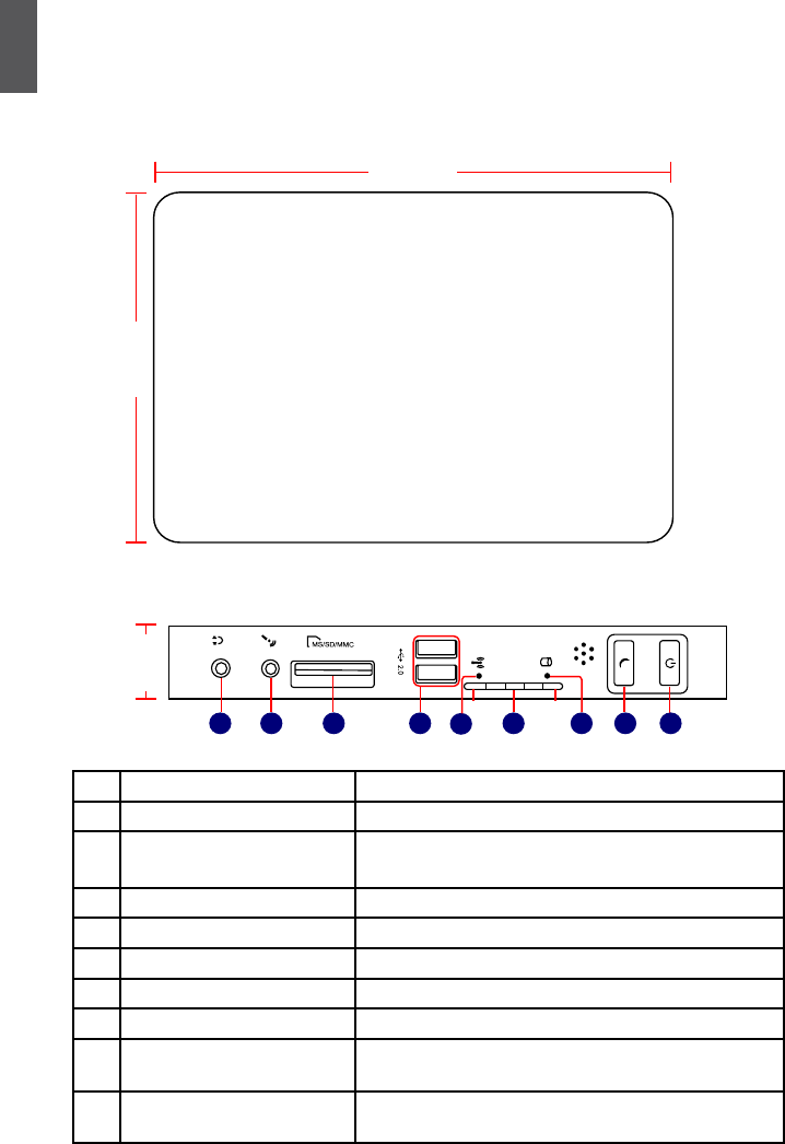
1-1 Product Overview
1. Top View
2. Front Side View
No. Name Description
1 Headphone Port Connects to a headphone
2
Microphone In and S/PDIF In
Port
Connects to a microphone or playback devices with
optical connectors(3.5mm jack)
3 Multi-Function Card Reader Supports SD/SDHC/MS/MS Pro/MMC memory cards
4 USB Ports Connect to USB devices
5WLAN_LED Indicates Wireless connection states
6LLS_LED Indicates different system states
7HDD_LED Indicates hard disk states
8 Suspend Button with
Integrated LED Indicator
Enter suspend mode in operating system
Indicates suspend states
9 Power Button with
Integrated LED Indicator
Turning the power on/off
Indicates system states
0.95in
(24mm)
1236 9
8
4 7
LLS_LED1 LLS_LED5
5
(190mm)
7.5in
5.3in
(135mm)
1
3
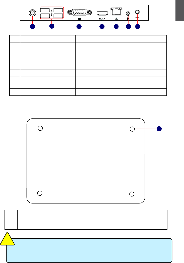
3. Back Side View
4. Bottom View
No. Name Description
1 Sheet Metal NETDVD(optional accessory) or Magnet-Metal-Feet can magnetize
them to seat rmly
There are four Magnet-Metal-Feet in the package. Just align them to the sheet metal
on the bottom, then they can magnetize the NETBOX easily. The feet can seat and
protect NETBOX when it is placed on the tabletop.
CAUTION
!
No. Name Description
1 RF(Radio Frequency) Port Connects to antenna
2 USB Ports Connect to USB devices
3Display Output Port(VGA) Connects to display device
4HDMI Port Connects to HDMI audio and video
5 Network Port Standard RJ-45 network port
6
Line Out and S/PDIF Out Port
Connects to powered analog speakers or record-
ing devices with optical connectors(3.5mm jack)
7 Power Input Port Connects to the power adapter
1
123 5
476

1
4
1-2 LED Indicator Introduction
The LLS_LEDs status in this table only show BIOS error message.
CAUTION
!
Indication Suspend_
LED
Power_
LED
HDD_
LED
WLAN_
LED
LLS_
LED1
LLS_
LED2
LLS_
LED3
LLS_
LED4
LLS_
LED5
Boot - Green Red
Blink - - - - - -
S0(Working Mode) - Green - - Off Off Off Off Off
S1(Power-Saving Mode) - Green Off - Off Off Off Off Off
S3(Standby Mode)
[Press Suspend Button]
Red
Blink - Off - Off Off Off Off Off
S4(Hibernation Mode)&
S5(System Power Off Mode)
- Off Off - Off Off Off Off Off
CPU
Initialization Error
- - - - Blue,
Blink - - - -
DRAM Error - - - - - Blue,
Blink - - -
BIOS Boot Block Fail - - - - - - - Blue,
Blink -
BIOS Checksum Error - - - - - - - - Blue,
Blink
CMOS Cleared [Press
Suspend Button for 4Sec.] -Red,
Blink - - - - - - -
HDD R/W Data - - Red - - - - - -
Wireless
Network
Enable
Link to AP - - - Blue - - - - -
No Link to AP - - - Blink
(Once every 5Sec.)
-----
Data
Transmission - - - Blink
(Indenite interval)
- - - - -

In this chapter, the placement and the connection of some neces-
sary peripherals will be introduced.
This chapter includes the following information:
■ Placement of NETBOX
■ Connection of NETBOX
2
6
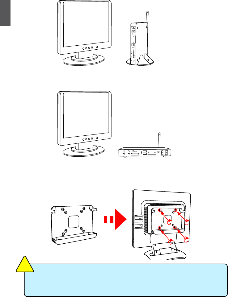
2-1 Placement of NETBOX
1. On the Desk
You can install your NETBOX in the mount directly.
If there is enough space on your desk, you can simply put your NETBOX with Magnet-Metal-
Feet on the tabletop.
2. On the Display Back
This is the best space-saving way.
2.1. Use four screws(M4X10mm) to fasten the bracket onto the display back.
To install this bracket, your display must follow VESA75/VESA100 standard. The two
groups of holes on your display have different space between, and they help you
easily fasten the bracket onto your display.
CAUTION
!
2
7
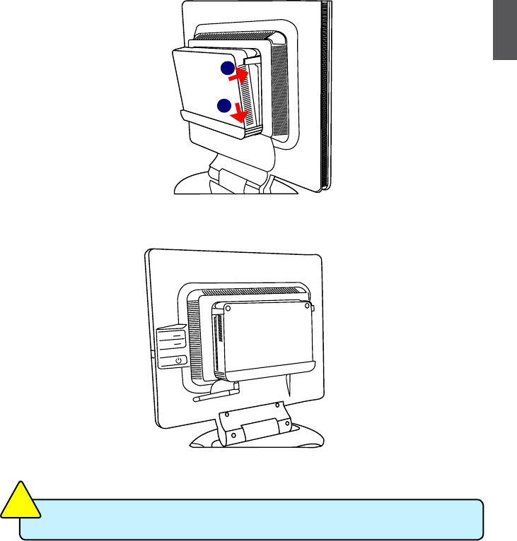
2.2. Fit the NETBOX into the bracket with power button locating at the top for easy touch.
2.3. After that, you can connect the antenna to your NETBOX.
Remove the antenna before lifting up the NETBOX straight to take it out.
CAUTION
!
2
1
2
8
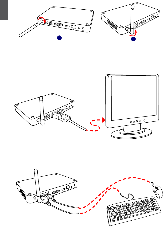
2-2 Connection of NETBOX
1. Connect the Antenna
Connect the antenna to the RF port of the NETBOX. You can fold the antenna and rotate it in
different angle as you want.
2. Connect the Monitor
Connect a monitor to the NETBOX through VGA connector or HDMI connector.
3. Connect the USB Devices
Connect USB devices to the USB ports of the NETBOX, for example, mouse and keyboard.
12
2
9
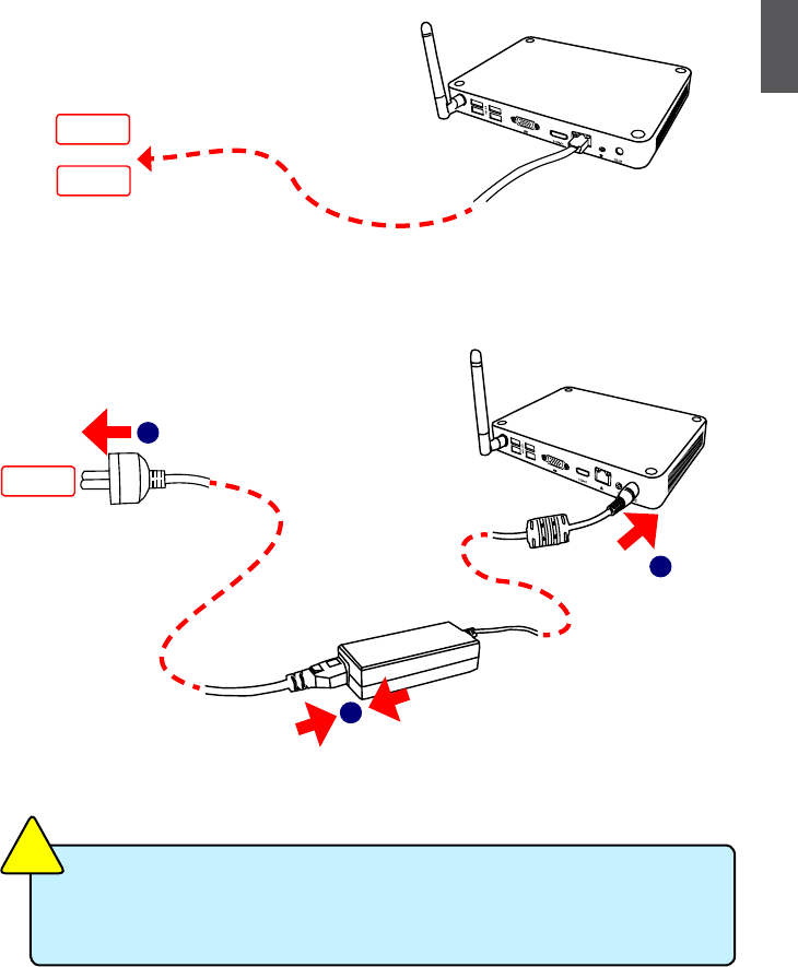
4. Connect the Network Cable
Connect LAN cable to the RJ-45 port, with the other end connected to a hub or switch.
5. Connect the Power Cord
Connect the power adapter to the power input port of the NETBOX, and push the power
button to start it.
The power adapter is dissipating heat during normal use, please make sure not to
cover it and keep it away from your body to prevent discomfort or injury from heat
exposure.
CAUTION
!
or
Hub
Switch
Outlet
2
3
1

This chapter introduces the following information:
■ Install Windows XP
■ Install Windows 7
■ Appendix - Display Features Notice
3
11
Make sure you have these ready :
1. NETDVD. (It is an optional accessory. If there is no NETDVD in this package, you need other
purchase an external USB DVD-ROM drive.)
2. NETBOX driver CD. (In this package)
3. Windows XP Install CD/Windows 7 Install CD. (Other purchase)
Before we continue :
■ Your NETBOX power is off.
■
Connect the NETDVD or USB DVD-ROM drive.
3-1 Install Windows XP
1. Install Windows XP
1.1. Push power on button to turn on your computer, then press <Del> key to enter BIOS Setup.
1.2. Put the Windows XP Install CD into the NETDVD or USB DVD-ROM drive.
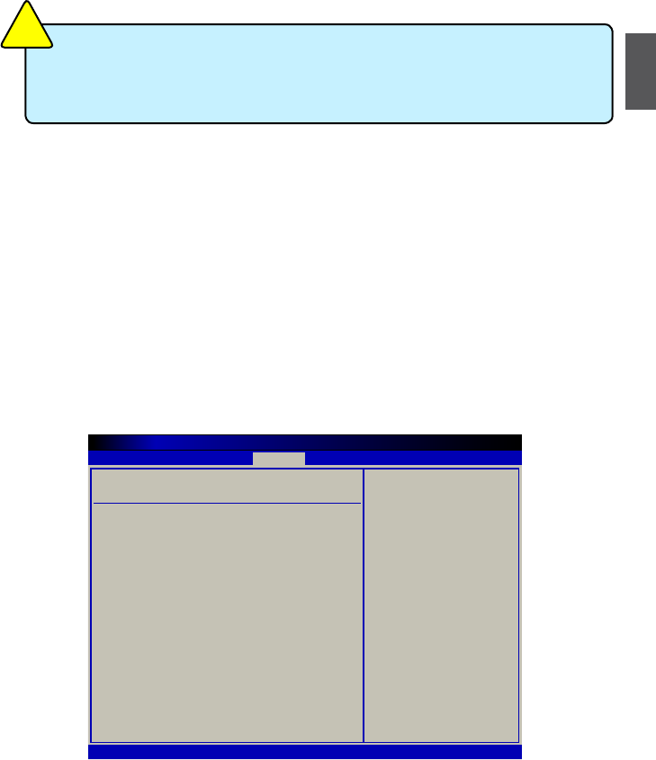
1.3. Select and go to the “Boot” menu, enter “Boot Device Priority”, set the “1st Boot Device” to
“USB: Optical DVD RW”, press <F10> key to save change and exit BIOS.
Boot Device Priority Specifies the boot
sequence from the
available devices.
1st Boot Device
[USB:Optical DVD RW]
2nd Boot Device
[SATA:PM-WDC WD1600]
A device enclosed in
3rd Boot Device
[USB:Generic- Multi]
parenthesis has been
disabled in the
corresponding type
menu.
← Select Screen
↑↓ Select Item
+/- Change Option
F1 General Help
F10 Save and Exit
ESC Exit
v02.67 (C) Copyright 1985-2009, American Megatrends, Inc.
BIOS SETUP UTILITY
Boot
The build-in graphics chipset of this Nettop only support upto Directx 9, can not up
to Directx 10 or later, which is recommended by Microsoft WHQL, but you can install
Operating System(Windows 7).
CAUTION
!

3
12
1.4. The computer will reboot, and it will start installing Windows XP Operating System.
1.5. Press <Enter> key to continue the installation.
1.6. Press <F8> key to accept the Licensing Agreement and continue.
1.7. Windows will display the hard disk partitions of your system. If previously there were other
systems (such as Linux) installed, you may need to press [D] key to delete them. When all
partitions are clean, setup will display the biggest size of your hard drive as depicted in step
1.8.
Windows XP Professional Setup
Welcome to Setup.
This portion of the Setup program prepares Microsoft(R)
Windows(R) XP to run on your computer.
● To set up Windows XP now, press ENTER.
● To repair a Windows XP installation using
Recovery Console, press R.
● To quit Setup without installing Windows XP, press F3.
ENTER=Continue R=Repair F3=Quit
Windows XP Professional Setup
The following list shows the existing partitions and
unpartitioned space on this computer.
Use the UP ad DOWN ARROW keys to select an item in the list.
● To set up on the selected item, press ENTER.
● To create a partition in the unpartitioned space, press C.
● To delete the selected partitions, press D.
152626 MB Disk 0 at Id 0 on bus 0 on atapi [MBR]
G: Partition2 [Unknown] 1757 MB <1757 MB free>
Unknown Disk
<There is no disk in this drive.>
Unknown Disk
<There is no disk in this drive.>
ENTER=Install C=Create Partition F3=Quit
F: Partition1 [Unknown] 150868 MB < 150868 MB free>

3
13
1.8. In this biggest hard disk size screen, you can press [C] to create partitions as you wish,
assign them C:, D: or E: logical drive names.
1.9. In this example, we are creating a 50GB partition C: for the system. Press <Enter> to install
Windows. The Windows XP install processes will ask you to format your hard disk, then copy
les...etc. Follow the installation steps until the whole process is completed.
Windows XP Professional Setup
The following list shows the existing partitions and
unpartitioned space on this computer.
Use the UP ad DOWN ARROW keys to select an item in the list.
● To set up Windows XP on the selected item, press ENTER.
● To create a partition in the unpartitioned space, press C.
● To delete the selected partitions, press D.
152626 MB Disk 0 at id 0 on bus 0 on atapi [MBR]
D: Partition2 [Unknown] 64464 MB < 64463 MB free>
Unpartitioned space 38163 MB
Unknown Disk
<There is no disk in this drive.>
Unknown Disk
<There is no disk in this drive.>
ENTER=Install C=Create Partition F3=Quit
C:Partition1 [NTFS] 49999 MB < 48568 MB free>
Windows XP Professional Setup
The following list shows the existing partitions and
unpartitioned space on this computer.
Use the UP ad DOWN ARROW keys to select an item in the list.
● To set up Windows XP on the selected item, press ENTER.
● To create a partition in the unpartitioned space, press C.
● To delete the selected partitions, press D.
152626 MB Disk 0 at id 0 on bus 0 on atapi [MBR]
Unknown Disk
<There is no disk in this drive.>
Unknown Disk
<There is no disk in this drive.>
ENTER=Install C=Create Partition F3=Quit
Unpartitioned space 152626 MB

3
14
2. Install Drivers in Windows XP
2.1. When the Windows XP is completely installed, you have to install the necessary drivers before
using the NETBOX. Take out the Windows XP Install CD from the DVD-ROM drive, and
put the NETBOX driver CD inside.
2.2. Waiting for a few seconds, the main menu will be displayed, click “Driver” to enter the Driver
menu shown as below:
2.3. Use these options to install all the drivers for your system. You must click "Intel Chipset Driver"
to install it rst. After that, you can click "One Click Setup" to install all the other drivers, or you
can click on each individual driver to install it manually.
2.4. After all the drivers are installed, you need to restart your NETBOX, then you can start using
it.
3
15
3-2 Install Windows 7
1. Install Windows 7
1.1. Push power button to turn on your computer, then press <Del> key to enter BIOS Setup.
1.2. Put the Windows 7 Install CD into the NETDVD or USB DVD-ROM drive.
1.3. Select and go to the “Boot” menu, enter “Boot Device Priority”, set the “1st Boot Device” to
“USB: Optical DVD RW”, press <F10> key to save change and exit BIOS.
1.4.
The computer will reboot, and it will start loading les for installing Windows 7 Operating
System.
1.5. After that, it will start Windows and come out a “Install Windows” dialog box to set the “Lan-
guage to install”, “Time and current format” and “ Keyboard or input method”. Click “Next” to
continue and click “Install now” button to start the setup.
1.6. When the license terms appear, select to accept and click “Next” to continue.
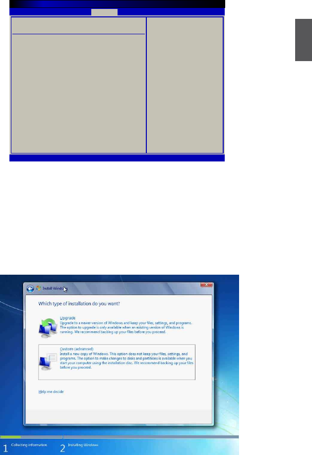
1.7.
It then asks you to select the installation type. Click “Custom (advanced)” to install a new copy of
Windows.
Boot Device Priority Specifies the boot
sequence from the
available devices.
1st Boot Device
[USB:Optical DVD RW]
2nd Boot Device
[SATA:PM-WDC WD1600]
A device enclosed in
3rd Boot Device
[USB:Generic- Multi]
parenthesis has been
disabled in the
corresponding type
menu.
← Select Screen
↑↓ Select Item
+/- Change Option
F1 General Help
F10 Save and Exit
ESC Exit
v02.67 (C) Copyright 1985-2009, American Megatrends, Inc.
BIOS SETUP UTILITY
Boot
3
16
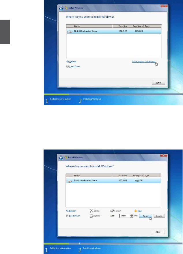
1.8. Later the setup will display the hard disk partitions of your system. If there were other
systems (such as Linux) installed previously, you need select them and click “Drive options
(advanced)” to delete them. When all partitions are clean, setup will display the biggest size
of your hard drive.
1.9. In this biggest hard disk size screen, you can click “New” button to create partitions as you
need. In this example, we will create a 70GB partition to install Windows, and click “Apply”.
3
17
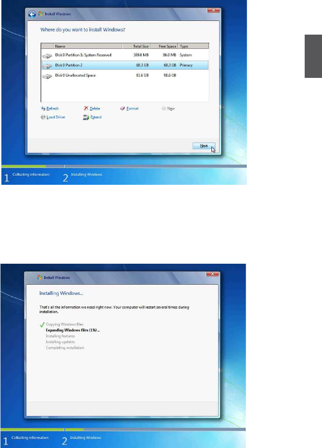
To ensure that all Windows features work correctly, Windows might create an additional parti-
tions for system les, so you will see a system reserved partition. Select the 70GB partition
and click “Next” to continue.
1.10. From this step we start to install windows 7 into your hard disk, including copying Windows
les, expanding Windows les...etc. During the installation, your computer will restart several
times.
3
18
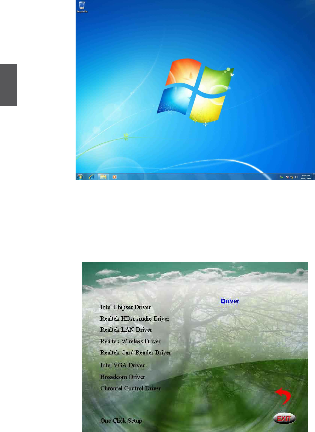
1.11. When the installation is completed, setup will prepare your compute for the rst use. Then
you can follow steps to select system settings, create an account, set a password...etc, until
the whole process is completed and enter
Windows 7 operating system
.
2. Install Drivers in Windows 7
2.1. When the Windows 7 is completely installed, you have to install the necessary drivers before
using the NETBOX. Take out the Windows 7 Install CD from the USB DVD-ROM drive, and
put the driver CD inside.
2.2. Waiting for a few seconds, the main menu will be displayed, click “Driver” to enter the Driver
menu shown as below:
2.3. Use these options to install all the drivers for your system. You must click "Intel Chipset Driver"
to install it rst. After that, you can click "One Click Setup" to install all the other drivers, or you
can click on each individual driver to install it manually.
2.4. After all the drivers are installed, you need to restart your NETBOX, then you can start using
it.
3
19
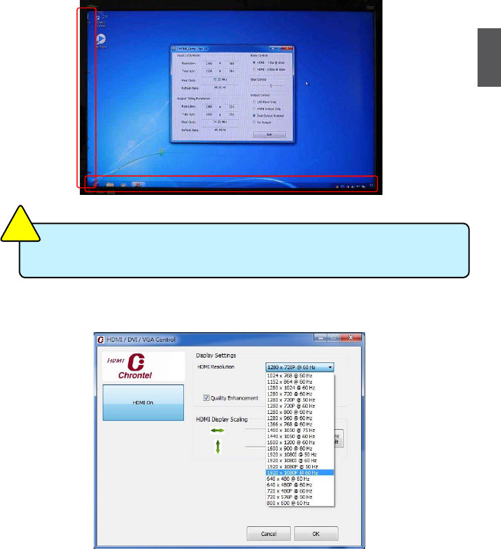
Appendix - Display Features Notice
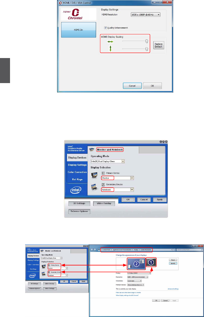
1. Chrontel HDMI Display Settings and Scaling
Some HDMI TV will display overscan mode as below, you can adjust it by using the Chrontel
HDMI Tool which appears after installing “Chrontel Control Driver”, otherwise, it can also be used
for the display resolution settings.
1.1. The resolution can be chosen from the drop-down list.
1.2. You can adjust the scaling by dragging the lever, to get the tting scale of display.
HDMI port support hotplug detecting, and the resolution support is base on the read-
ing EDID information!
CAUTION
!
3
20
Note: Click the “HDMI On” button in the left can close the HDMI output, you can reopen it by
re-plugging the HDMI cable.
2. Display Instruction in OS(Windows XP/Vista/7)
2.1. In the Intel® Graphics Media Accelerator Driver, the VGA(D-sub) port is dened as “Monitor”,
and the HDMI port is dened as “Notebook”.
2.2. In Windows 7 system, the output sequence in the Intel® Graphics Media Accelerator Driver
and the OS display properties are nonmatched, the “Primary Device” match for “2”, and the
Secondary Device match for “1”.
3
21
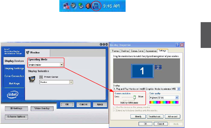
2.3. For the VGA user, after installing VGA Driver, and rebooting into system, the VGA default
Operating Mode is "Intel(R) Dual Display Clone", and the "Screen resolution" is held to “1280
x 720”. If you want to adjust the screen resolution, please follow the steps below to select the
“Single Display” in "Operating Mode”.
Step 1. Double click the Intel® Graphics Media Accelerator Driver icon in the system tray.
Step 2. In the “Display Devices” tab, select “Single Display” from the “Operation Mode”
drop-down list. Then you can adjust the “Screen resolution” as you want.
3. HD Video Play Notice
If you want to play HD videos, the .WMV, .MOV and .VOB formats are recommended.
Statement:
This device complies with part 15 of the FCC Rules. Operation is subject to the following two
conditions: (1) This device may not cause harmful interference, and (2) this device must
accept any interference received, including interference that may cause undesired operation.
Warning:
FEDERAL COMMUNICATIONS COMMISSION INTERFERENCE STATEMENT
This equipment has been tested and found to comply with the limits for a Class B digital
device, pursuant to part 15 of the FCC Rules. These limits are designed to provide reasonable
protection against harmful interference in a residential installation. This equipment generates,
uses and can radiate radio frequency energy and, if not installed and used in accordance with
the instructions, may cause harmful interference to radio communications. However, there is
no guarantee that interference will not occur in a particular installation. If this equipment does
cause harmful interference to radio or television reception, which can be determined by turning
the equipment off and on, the user is encouraged to try to correct the interference by one or
more of the following measures:
▪ Reorient or relocate the receiving antenna.
▪ Increase the separation between the equipment and receiver.
▪ Connect the equipment into an outlet on a circuit different from that to which the receiver
is connected.
▪ Consult the dealer or an experienced radio/ TV technician for help.
Caution:
Any changes or modications not expressly approved by the grantee of this device could
void the user’s authority to operate the equipment.
RF exposure warning:
This equipment must be installed and operated in accordance with provided instructions and
the antenna(s) used for this transmitter must be installed to provide a separation distance of at
least 20 cm from all persons and must not be co-located or operating in conjunction with any
other antenna or transmitter. End-users and installers must be provide with antenna installation
instructions and transmitter operating conditions for satisfying RF exposure compliance.
