FrSky Electronic D8TD8R 2.4GHz Radio System User Manual
FrSky Electronic Co., Ltd. 2.4GHz Radio System
user manual

FinePrint Software, LLC
16 Napier Lane
San Francisco, CA 94133
Tel: 415-989-2722
Fax: 209-821-7869
www.fineprint.com
Manual of Two-Way Radio System www.FrSky-rc.com P1of7
2.4GHz Two-Way Radio System
1. Introduction:
The Two-way Radio System developed by FrSky provides an additional
return link that would be used for monitoring the Rx’s voltage, temperature,
location, speed and so on.
2. Overviews
2.1 Transmitter modules:
a) Model: DFT
Compatible with the following transmitters:
Futaba: 3PM, 3PK, 7U, 8U, 8J, 9C, 9Z, 10C, FN series, T10C, FC-18,
FC-28.
Hitec: Optic 6, Eclipse 7, Prism 7.
WFLY: WFT09, WFT08.
b) Model: DJT
Compatible with the following transmitters:
JR: 347/388/783/U8/PCM10/PCM10S/PCM10SX/
PCM10IIS/8103/J9303/MX-22/MX-24S/PX/9XII.
2.2 Receiver module:
a) Model: D8R, D8RHV
Compatible with FrSky Two Way module DFT/DJT.
b) Model: V8R, V8RHV, V8R7, V8R7HV, V8R4
V8 receivers work with DFT/DJT, just in receive-only mode.
3. Features
a) Advanced Continuous Channel Shifting Technology (ACCST
SYSTEM) achieves high reliable link in interference rich
environments.
b) Easy to bind and instant link-up.
c) Excellent reboot times.
d) All channels failsafe.
e)
Quick r
esponse.
Manual of Two-Way Radio System www.FrSky-rc.com P2of7
f) Very smooth servo movement.
g) Alarm on events of receiver (low battery voltages, poor reception,
etc.)
h) Error-free link, by using 48bits CRC algorithm.
i) Low power consumption.
j) True two-antenna diversity.
k) Firmware upgradable.
4. Function of Two Way communication
a) Two way communication between receiver and transmitter
b) Receiver is able to accept 2 analog inputs, which can be used to monitor
battery voltage, temperature sensor, etc., and transfer them to
transmitter. Users can set the Alarm Point of these analog voltages, when
exceed or below these points, sound alarm is presented.
c) Receiver is able to accept serial data streams from simple 3-wire RS232
port, such information as GPS, altitude, and user developed data can be
transferred to Tx without error, and presented at the RS232 port on the
Tx.
5. Specifications
5.1 Receiver specifications:
Model: D8R
Weight: 16.2g
Dimension: 54*27*17mm
Operating Voltage Range: 4.0V-7.2V
Operating Current: 100mA
Specified Range: 1.5km (Ground Range)
Resolution: 11bit (3072)
Latency: 22ms
Number of Channels: 8CH
Analog voltage: 0~3.3V
5.2 Transmitter module specifications:
Model: DFT, DJT
PDF 文件使用 "pdfFactory Pro" 试用版本创建 www.fineprint.cn
Manual of Two-Way Radio System www.FrSky-rc.com P3of7
Operating Voltage Range: 6.0V-13.0V
Operating Current: 50mA
Output Power: 60mW
Resolution: 11bit (3072)
Important!
The effective range of control refers to the distance between the
transmitter and the receiver clear of obstruction. All data was tested and
verified by FrSky.
However this is not guaranteed due to many factors such as the flying
environment and the weather, which can greatly affect the effective range of
control.
It is extremely important to range check your models prior to
each flying session!
6. How To Use
6.1 Setup
6.1.1 Installation of the transmitting module:
a) Remove the original transmitting module.
b) Put the FrSky 2.4GHz transmitter module into the module port of your RC
transmitter and screw on the transmitting antenna.
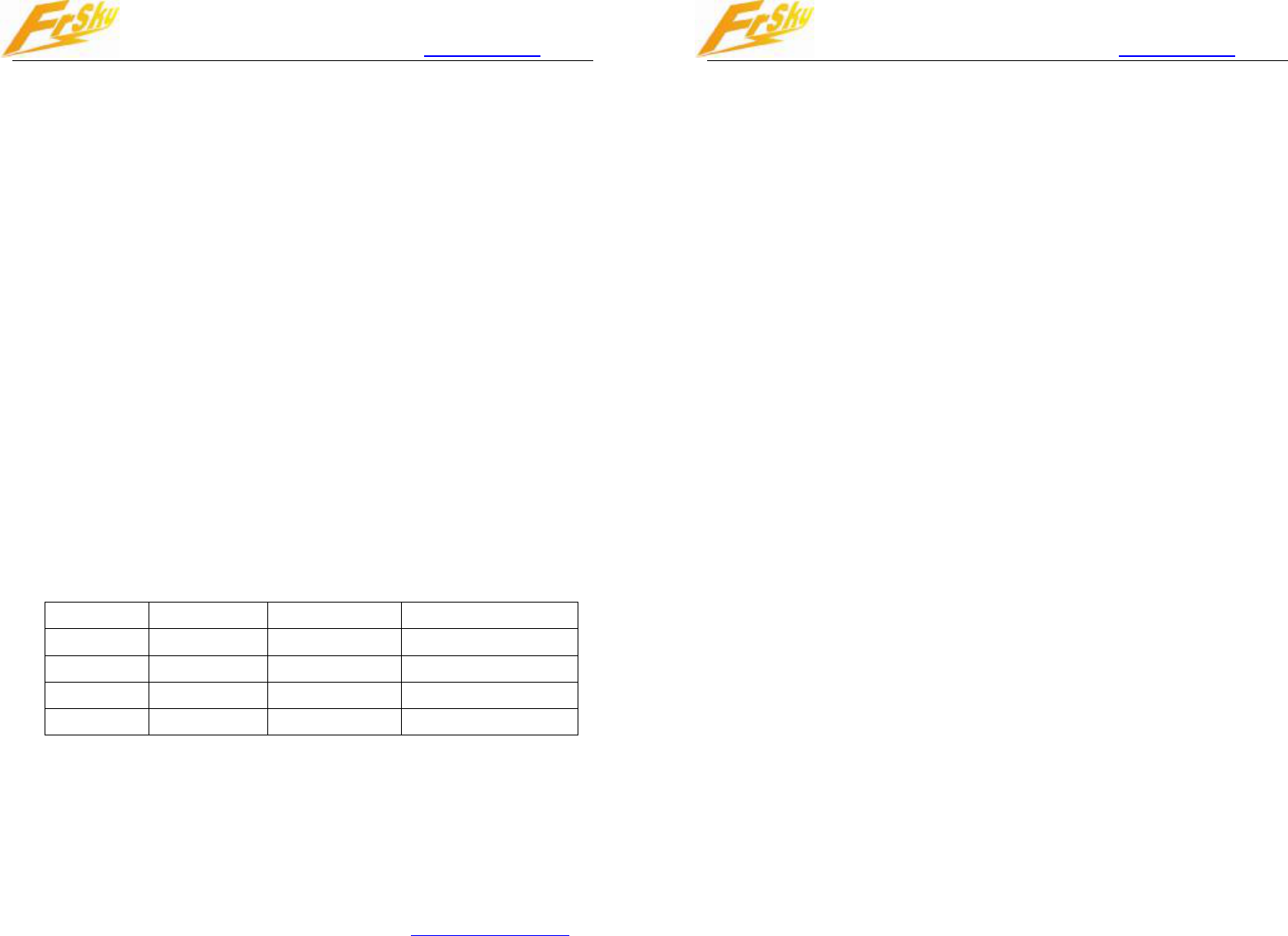
c) Check the MODE switch to its corresponding position.
Mode Switch 1 Switch 2 Mode
1 OFF OFF Two-way Mode
2 OFF ON V8 Mode
3 ON OFF Not Defined
4 ON ON Firmware Upgrade
d) Turn the transmitter power on and check the LED status on the module.
6.1.2 Installation of receivers:
The D8R receiver incorporates two separate antennas which enable them
to receive the radio signal at two different locations. please make sure that the
two antennas be apart placed and 90 degrees crossed.
Please note:
As the wave length of
2.4GHz is shorter than older RC systems, its ability
Manual of Two-Way Radio System www.FrSky-rc.com P4of7
to go around solid obstacles is weaker than 72 or 36 MHz. So the antennas
must avoid objects with high conductivity, such as metal parts, servos, ESC’s,
battery packs, wires, and carbon fiber structures. If possible put the tip of the
antennas outside of the fuselage for maximum reception.
6.1.3 Receiver and Transmitter Setup Instructions:
Follow the steps below to properly set up your system.
a) Turn your FUTABA or JR transmitter on and switch it to PPM mode, power
off the TX.
b) Check the working mode of the Tx module.
c) Turn the transmitter on while holding the programming button. Release it
a few seconds later. The RED LED on the transmitter module will flash
indicating the transmitter is ready to bind the receivers.
d) Connect the battery to the receiver while holding the receiver’s button.
The LED on the receiver will flash indicating the binding process is
complete. Turn off the receiver.
e) Turn off the transmitter and receiver to finish the binding procedure.
f) Turn on the transmitter.
g) Connect the battery to the receiver, the Green LED on the receiver will
indicate the receiver is receiving commands from the transmitter.
After the steps above are completed, both the transmitter and receiver are
ready to be used.
6.2 Range check
For safe operation, it is necessary to perform pre-flight range check.
Caution must be paid when the units in the environment of metal fences,
concrete buildings, or rows of trees. Loss of signal may be experienced.
Perform a range check as follows (Note: this would be done with the
receiver installed in the model):
a) Place the model at least two feet (60cm) above non-metal contaminated
ground; for example a wooden bench.
b) Place the receiver’s antenna apart. Do NOT let the antenna touch the
ground.
PDF 文件使用 "pdfFactory Pro" 试用版本创建 www.fineprint.cn
Manual of Two-Way Radio System www.FrSky-rc.com P5of7
c) Place the antenna of the transmitter in a vertical position.
d) Turn on the transmitter and receiver.
e) To enter Range Check Mode, press and hold the “F/S Range” button of the
transmitter for 4 second, the RED LED of the transmitter module will be
turned off, the effective distance will be decreased to 1/30.
f) Walk away from the model while simultaneously operating the controls on
the transmitter, confirm that all controls are completely and correctly
operational at least 30 meters away.
g) Press the “F/S Range” button for 1S-4S, the transmitter will exit Range
Check Mode.
7 Safety range indicator
The Two-Way Radio System has a feature to show the RSSI (Received Signal
Strength Indication) of the receiver. When the RSSI is low, the Tx module would give out
three types of alarm.
Red: The receiver is very far from the Tx.
Orange: The receiver is sound, but would be far from Tx.
Yello: The receiver is sound,
Green: The receiver is OK.
Note: Due to many environment factors, there may be casual alarm.
8 Failsafe
The receiver integrates the failsafe function for all channels.
To set failsafe positions, press briefly(less then 1 second) the “F/S
Range” button of the Receiver, the Tx module will make a long “beep”
indicating the failsafe position is remembered by the receiver.
9 Alarm operation
9.1 Alarm states
Tx module monitors the state of receiver and notify user by audible
alarm.
The alarm state is made a distinction between three levels:
Red (Highest): constant three Beeps
Orange
(Medium):
constant
two
Beeps
Manual of Two-Way Radio System www.FrSky-rc.com P6of7
Yellow (General): one Beep
Green: No Beep
Alarm sourced from:
-Rx interface 1: Analog Port 1 on Rx;
-Rx interface 2: Analog Port 2 on Rx;
-Rx interface 3: RSSI of Rx;
Note: The alarm threshold of Rx interface 1 and 2 could be set by
user. Two alarm thresholds and three levels alarm state are available
for both of Rx interface 1 and 2.
And the RSSI alarm setting is default by factory.
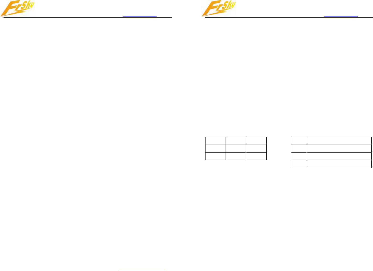
9.2 Pins Definition:
The Pin definition on receiver and Tx module:
It should be noted that the 3.3V voltage only have a limited driving
current (1~10mA), should not be used for driving a MPU.
RXD +5V GND
AD2 × GND
AD1 × GND
RXD
Input to Tx module
TXD
Output from Tx module
+5V
Not regulated voltage
GND
Ground
RXD: input to receiver, RS232 level
AD2: Voltage: max 3.3V
AD1: Voltage: max 3.3V
Pins Definition at Rx Pins Defini
tion at Tx
10 LED Status:
10.1 LED status on Transmitter module:
Red LED on and Green LED flashing: Working Mode.
Red LED off and Green LED flashing: Range Check Mode.
Red LED flashing: Binding Mode.
10.2 LED status on Receiver:
Red LED on and Green LED
gloom
ing:
Working
Mode
.
PDF 文件使用 "pdfFactory Pro" 试用版本创建 www.fineprint.cn

Manual of Two-Way Radio System www.FrSky-rc.com P7of7
Red LED flashing and Green LED off: No Signal.
Red LED flashing and Green LED on: Binding OK.
11 Firmware Upgrade
Frsky have developed a machanism of firmware upgrade. With it, user
would like to upgrade to new version of software when available. And the
Two-Way Radios System is supported by this machanism.
Steps are followed:
a) Set module to Upgrade Mode.
b) Connect the module to PC through a RS232 cable.
c) Start Upgrade software on PC.
d) Select file and corresponding port.
e) After the Serial No. is got, press Download.
f) After the progress bar reached 100%, the software of the module is
updated.
* For more information, please kindly refer to the Two Way
Protocol.
12 Contact Information
Sales: Mr. Jonathan Zhou
E-mail: jonathanfreesky@gmail.com
Mobile: +86-1525-1608-252
MSN: jonathanfreesky@hotmail.com
Skype: jonathanfreesky
Sales: Ms. Eva Liu
E-mail: evafrsky@gmail.com
Mobile: +86-1358-5022-162
MSN: liuyunjieeva@hotmail.com
Skype: evaliu0409
Technical support:
E
-
mail:
sales4tech@gmail.com
PDF 文件使用 "pdfFactory Pro" 试用版本创建 www.fineprint.cn
FCC STATEMENT
1. This device complies with Part 15 of the FCC Rules. Operation is subject to the following two conditions:
(1) This device may not cause harmful interference.
(2) This device must accept any interference received, including interference that may cause undesired operation.
2. Changes or modifications not expressly approved by the party responsible for compliance could void the user's
authority to operate the equipment.
NOTE: This equipment has been tested and found to comply with the limits for a Class B digital device,
pursuant to Part 15 of the FCC Rules. These limits are designed to provide reasonable protection against
harmful interference in a residential installation.
This equipment generates uses and can radiate radio frequency energy and, if not installed and used in
accordance with the instructions, may cause harmful interference to radio communications. However, there
is no guarantee that interference will not occur in a particular installation. If this equipment does cause
harmful interference to radio or television reception, which can be determined by turning the equipment off
and on, the user is encouraged to try to correct the interference by one or more of the following
measures:
Reorient or relocate the receiving antenna.
Increase the separation between the equipment and receiver.
Connect the equipment into an outlet on a circuit different from that to which the receiver is connected.
Consult the dealer or an experienced radio/TV technician for help.
The SAR limit of USA (FCC) is 1.6 W/kg averaged over one gram of tissue.
Device types D8T (FCC ID: XYFD8TD8R) has also been tested against this
SAR limit. The highest SAR value reported under this standard during product
certification for use on the body is 1.408 W/kg.