FrSky Electronic W2409T 2.4G Radio System User Manual XJT manual fcc
FrSky Electronic Co., Ltd. 2.4G Radio System XJT manual fcc
User manual
1
www.frsky‐rc.com
05/09/13
InstructionManualforFrSky2.4GRADIOSYSTEMXJTModule
Introduction
ThankyouforpurchasingFrSky2.4GRADIOSYSTEMXJTmodule.Inordertofullyenjoythebenefitsofthissystem,please
readtheinstructionmanualcarefullyandsetupthedeviceasdescribedbelow.
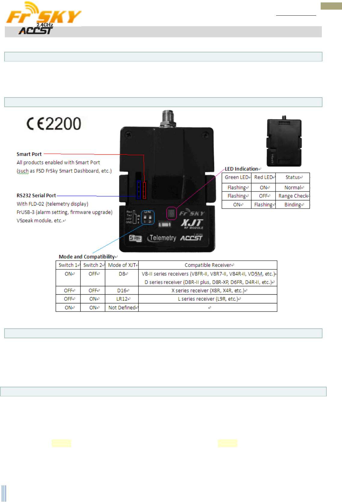
Overview
Specifications
OperatingVoltageRange:6~15V
OperatingCurrent:140mA@6V
OutputPower:≤100mW
ModuleSlot:JR/GraupnerType
Modulations:PXXorCPPM(auto‐detected)
Modes:D8,D16orLR12(selectable)
TelemetryInterface:SmartPort,RS232SerialPort
UpgradeInterface:SmartPort,RS232SerialPort
What’sNew!
Twoauto‐detectedmodulationsofPXX(modeselection,bind,modelmatch,rangecheck,failsafe,etc.onradioside)
orCPPM.
ThreeselectablemodesofD8(existing8chtwo‐way),D16(new16chtwo‐wayfullduplextransmission)andLR12
(new12chone‐waylongrange).
SmartPortenabled,realizingtwo‐wayfullduplextransmission.
Detectthemoduleantenna’sworkingstatusandgivesoundwarningsifthemoduleantennaisbrokenordoesnot
haveintactcontact,etc.
Superlowerlatency(approx.1/3ofcurrentsystems)andhigherprecision(transmitter’shardwareandsoftware
supportrequired,suchasFrSkytransmitters).
2
www.frsky‐rc.com
05/09/13
BindingProcedure
Bindingistheprocessofuniquelyassociatingaparticularreceivertoatransmittermodule.Atransmittermodulecanbe
boundtomultiplereceivers(nottobeusedsimultaneously).Areceivercanonlybeboundtoonetransmittermodule.Follow
thestepsbelowtofinishthebindingprocedure.
1. TurnonthetransmitterwhileholdingtheF/Sbuttononthe2.4GRADIOSYSTEMXJTmodule(seeModeand
Compatibilitytableabove).Releasethebutton.TheREDLEDonthe2.4GRADIOSYSTEMXJTmodulewillflash,
indicatingthetransmitterisreadytobindtothereceiver.
2. ConnectthebatterytothereceiverwhileholdingtheF/Sbuttononthereceiver.TheREDLEDonthereceiverwill
flash,indicatingthebindingprocessiscompleted(pleaserefertothecorrespondingreceiver’sinstructionmanual
fordetails)
3. Turnoffboththetransmitterandthereceiver.
4. Turnonthetransmitterandconnectthebattery.TheREDLEDonthereceiverindicatesthereceiverisreceiving
commandsfromthetransmitter.Thereceiver/transmittermodulebindingwillnothavetoberepeated,unless
oneofthetwoisreplaced.
Note:Afterbindingprocedureiscompleted,recyclethepowerandcheckifthereceiverisreallyundercontrolbylinked
transmitter.
RangeCheck
Apre‐flightrangecheckshouldbedonebeforeeachflyingsession.Reflectionsfromnearbymetalfences,concretebuildings
ortreescancauselossofsignalbothduringrangecheckandduringtheflight.
Followthestepsbelowtoperformtherangecheck.
1. Placethemodelatleast60cm(twofeet)abovenon‐metalcontaminatedground(e.g.onawoodenbench).
2. Thereceiverantennasshouldbeseparatedinthemodel,anddonottouchtheground.
3. Themoduleantennashouldbeinaverticalposition.
4. Turnonthetransmitterandthereceiver,presstheF/Sbuttononthe2.4GRADIOSYSTEMXJTmodulefor4
secondstoenterrangecheckmode,theREDLEDwillbeoff,GREENLEDwillflashrapidly.Theeffectivedistance
willbedecreasedto1/30offullrange.
5. Walkawayfromthemodelwhilesimultaneouslyoperatingthecontrolsonthetransmittertoconfirmallcontrols’
normaloperation(pleaserefertothecorrespondingreceiver’sinstructionmanualfordetails).
6. PresstheF/Sbuttononthe2.4GRADIOSYSTEMXJTmodulefor1~4secondstoexitrangecheckmode,REDLED
willbebackon,indicatingnormaloperationisback.
SafeFlyingDistance
FrSkytelemetrysystemhasafeaturetoreturntheReceivedSignalStrengthIndication(RSSI)ofthereceivertothetransmitter.
Thetransmitterdevelopsaninternalvoltagerepresentingthereceiversignalstrength.Alarmsareprogrammedinthe
transmittertowarnthepilotwhenthemodelisnearingmaximumcontrolrange.Seethetablebelowforreference.
NumberBeepAlarmingMeaning
0NoBeepThesignalstrengthisstrong
1SingleBeepThesignalstrengthisadequate
2ConstantdoubleBeepsThemodelisfar,butsaferange
3ConstanttripleBeepsThemodelinnearmaximumrange
ConstantBeepsThe module antennaisbroken
,
ordoesnothaveintactcontact
,
etc.
FrSkyElectronicCo.,Ltd.
Tel:(86)510‐85187718Fax:(86)510‐85187728
E‐mail:frsky@frsky‐rc.comTechnicalSupport:sales4tech@gmail.com
SmartPort(S.Port)isasignalwirefullduplexdigitaltransmissioninterfacedevelopedbyFrSkyElectronic
Co.,Ltd.AllproductsenabledwithSmartPort(includingXJTmodule,X8Rreceiver,newhub‐lesssensors,newSmart
Dashboard,etc),serialportuserdataandotheruserinput/outputdevicescanbeconnectedwithoutlimitationsfor
numbersorsequencesatahightransmissionspeed.
FCC STATEMENT
1. This device complies with Part 15 of the FCC Rules. Operation is subject to the following two
conditions:
(1) This device may not cause harmful interference.
(2) This device must accept any interference received, including interference that may cause
undesired operation.
2. Changes or modifications not expressly approved by the party responsible for compliance could
void the user's authority to operate the equipment.
NOTE: This equipment has been tested and found to comply with the limits for a Class B digital
device, pursuant to Part 15 of the FCC Rules. These limits are designed to provide reasonable
protection against harmful interference in a residential installation.
This equipment generates uses and can radiate radio frequency energy and, if not installed and
used in accordance with the instructions, may cause harmful interference to radio communications.
However, there is no guarantee that interference will not occur in a particular installation. If this
equipment does cause harmful interference to radio or television reception, which can be
determined by turning the equipment off and on, the user is encouraged to try to correct the
interference by one or more of the following measures:
Reorient or relocate the receiving antenna.
Increase the separation between the equipment and receiver.
Connect the equipment into an outlet on a circuit different from that to which the receiver is
connected.
Consult the dealer or an experienced radio/TV technician for help.
FCC Radiation Exposure Statement
This equipment complies with FCC radiation exposure limits set forth for an uncontrolled
environment. This equipment should be installed and operated with minimum distance 20cm
between the radiator & your body