FreeFlight Systems FDL978XXXX UAT Transceiver User Manual FreeFlight FCC Application
FreeFlight Systems UAT Transceiver FreeFlight FCC Application
Manual
FDL-978-TX ADS-B
Transmitter Installation Manual
This document contains FreeFlight Systems proprietary information. It is loaned for limited purposes only and
remains the property of FreeFlight Systems. It may not be reproduced in whole or in part without written consent of
FreeFlight Systems and must not be disclosed to persons not having need of such disclosure consistent with the
purpose of the loan. The document is to be returned to FreeFlight Systems upon request and/or upon completion of
the use for which it was loaned
September 1, 2011
EQUIPMENT INSTALLATION MANUAL
For the
FreeFlight Systems
FDL-978-TX Transmitter (P/N 85595-00)
Document No: 86960 Revision A
FreeFlight Systems
3700 Interstate 35 S.
Waco, TX 76706

86960, Revision A September 1, 2011
History of Revisions
Dates of Original and Change pages are:
Revision ….. A …………… September 1, 2011
Page Description Page no. Date

FDL-978-TX ADS-B
Transmitter Installation Manual
86960, Revision A September 1, 2011
i
Table of Contents
SECTION I GENERAL INFORMATION .........................................................................................I-1
1.1 INTRODUCTION ............................................................................................................................I-1
1.2 GENERAL SYSTEM DESCRIPTION .................................................................................................I-1
1.2.1 FDL-978-TX Transmitter........................................................................................................I-2
1.2.2 TC-978 Front Panel Controller..............................................................................................I-3
1.2.3 UAT Antenna Requirements ...................................................................................................I-4
1.3 TECHNICAL CHARACTERISTICS....................................................................................................I-5
1.3.1 FDL-978-TX Transmitter........................................................................................................I-5
1.3.2 TC-978 Front Panel Controller..............................................................................................I-6
1.4 PARTS AND EQUIPMENT...............................................................................................................I-7
1.4.1 FDL-978-TX Transmitter Items..............................................................................................I-7
1.4.2 TC-978 Front Panel Controller Items ....................................................................................I-7
1.4.3 Installation Kits ......................................................................................................................I-7
1.5 MATERIALS REQUIRED BUT NOT SUPPLIED ................................................................................I-8
SECTION II INSTALLATION.......................................................................................................II-1
2.1 GENERAL ................................................................................................................................... II-1
2.2 UNPACKING AND INSPECTING EQUIPMENT ................................................................................ II-1
2.3 EQUIPMENT MOUNTING............................................................................................................. II-1
2.3.1 TC-978 Mounting .................................................................................................................II-1
2.3.2 FDL-978-TX Mounting......................................................................................................... II-1
2.4 COOLING REQUIREMENTS.......................................................................................................... II-2
2.5 FDL-978-TX UAT ELECTRICAL CONNECTIONS........................................................................ II-3
2.5.1 FDL-978-TX Interface – Pinout ........................................................................................... II-3
2.6 FDL-978-TX UAT INTERFACE DETAILS ................................................................................... II-4
2.6.1 Power Input .......................................................................................................................... II-4
2.6.2 Personality Module............................................................................................................... II-4
2.6.3 Status LEDs .......................................................................................................................... II-5
2.6.4 Controller Interface.............................................................................................................. II-5
2.6.5 Physical Serial Interfaces..................................................................................................... II-5
2.6.6 Discrete Inputs...................................................................................................................... II-8
2.6.7 Discrete Output..................................................................................................................... II-9
2.6.8 TX Suppression Output......................................................................................................... II-9
2.6.9 Time Mark Input (PPS)......................................................................................................... II-9
2.6.10 Maintenance Interface...................................................................................................... II-9
2.7 TC-978 CONTROLLER ELECTRICAL CONNECTIONS ..................................................................II-11
2.7.1 TC-978 Connection – Pinout...............................................................................................II-11
2.8 TC-978 CONTROLLER INTERFACE DETAILS..............................................................................II-11
2.8.1 Power...................................................................................................................................II-11
2.8.2 Remote ON...........................................................................................................................II-11
2.8.3 TMAP Bus............................................................................................................................II-11
2.8.4 Altitude Out .........................................................................................................................II-11
2.9 PERSONALITY MODULE INSTALLATION ....................................................................................II-11
2.10 WIRING CONSIDERATIONS ........................................................................................................II-13
2.11 UAT ANTENNA INSTALLATION ................................................................................................II-13
2.11.1 UAT Antenna Ground Plane ...........................................................................................II-13
2.11.2 UAT Antenna Cable ........................................................................................................II-14
2.12 STATIC PRESSURE CONNECTION ...............................................................................................II-15
2.13 EQUIPMENT LIMITATIONS .........................................................................................................II-15
SECTION III CONFIGURATION AND CHECKOUT................................................................III-1
3.1 GENERAL .................................................................................................................................. III-1
3.1.1 Continued Airworthiness Requirements .............................................................................. III-1

FDL-978-TX ADS-B
Transmitter Installation Manual
86960, Revision A September 1, 2011
ii
3.1.2 Normal Controller Operation.............................................................................................. III-1
3.2 PRELIMINARY CHECKOUT......................................................................................................... III-4
3.3 INSTALLATION SETUP AND CONFIGURATION ............................................................................ III-5
3.3.1 Configuration Item Summary ..............................................................................................III-5
3.4 CONFIGURATION MODE ............................................................................................................ III-6
3.4.1 Entering Configuration Mode.............................................................................................. III-6
3.5 CONFIGURATION MODE SETUP ................................................................................................. III-6
3.5.1 Aircraft Modes S (or ICAO) Address................................................................................... III-7
3.5.2 VFR Squawk Code............................................................................................................... III-7
3.5.3 Call Sign/VFR Flight ID...................................................................................................... III-7
3.5.4 Maximum Airspeed.............................................................................................................. III-8
3.5.5 Aircraft (Emitter) Category................................................................................................. III-9
3.5.6 Squat Switch Type................................................................................................................ III-9
3.5.7 Serial IN Channel X Data Type......................................................................................... III-10
3.5.8 Serial IN Channel X Line Speed........................................................................................ III-10
3.5.9 Serial OUT Channel X Data Type..................................................................................... III-11
3.5.10 Serial OUT Channel X Line Speed................................................................................ III-11
3.5.11 ARINC IN Channel X Data Type................................................................................... III-12
3.5.12 ARINC IN Channel X Interface Speed........................................................................... III-12
3.5.13 GPS Certification.......................................................................................................... III-13
3.5.14 GPS NAC Velocity......................................................................................................... III-13
3.5.15 Aircraft Length.............................................................................................................. III-14
3.5.16 Aircraft Width................................................................................................................ III-14
3.5.17 GPS Reference Position Offset...................................................................................... III-14
3.5.18 1090 MHz Receiver Installed ........................................................................................ III-16
3.5.19 UAT Receiver Installed ................................................................................................. III-16
3.5.20 UAT Antenna Diversity ................................................................................................. III-16
3.5.21 Check Ground on UAT Antenna.................................................................................... III-17
3.6 TEST AND CALIBRATION......................................................................................................... III-17
3.6.1 Local Voltage Supply Test................................................................................................. III-17
3.6.2 Calibrate Altitude Encoder................................................................................................ III-18
3.6.3 Pressure Altitude Reported................................................................................................ III-20
SECTION IV TROUBLESHOOTING ...........................................................................................IV-1
4.1 GENERAL ..................................................................................................................................IV-1
4.2 FDL-978-TX LED TROUBLSHOOTING PROCEDURE ..................................................................IV-1
4.2.1 UAT Status LED/Discrete Fault Indications ....................................................................... IV-2
4.3 WARNING MESSAGES ...............................................................................................................IV-3
4.3.1 TC-978 Warning Message Troubleshooting........................................................................ IV-3
SECTION V RTCA/DO-160 ENVIRONMENTAL QUALIFICATION FORMS ..................... V-1
5.1 FDL-978-TX UAT DO-160 QUALIFICATION ............................................................................ V-1
5.2 TC-978 CONTROLLER DO-160 QUALIFICATION ................................................................... V-2
SECTION VI SERIAL INTERFACE SPECIFICATIONS ..........................................................VI-1
6.1 ALTITUDE ENCODER FORMAT......................................................................................... VI-1
6.2 AIR DATA COMPUTER FORMAT....................................................................................... VI-1
SECTION VII ADS-B COMPLIANCE.......................................................................................... VII-1
SECTION VIII INSTALLATION DRAWINGS.......................................................................VIII-1
8.1 FDL-978-TX TRANSMITTER DIMENSIONS............................................................................. VIII-1
8.2 TC-978 CONTROLLER DIMENSIONS....................................................................................... VIII-2
8.3 FRONT PANEL CUT-OUT OPTIONS.......................................................................................... VIII-2
SECTION IX INTERCONNECT DIAGRAMS.............................................................................IX-1

FDL-978-TX ADS-B
Transmitter Installation Manual
86960, Revision A September 1, 2011
iii
9.1 FDL-978-TX INTERCONNECT DIAGRAM WITH 1201 GPS/SBAS SENSOR................................IX-1
9.2 FDL-978-TX INTERCONNECT DIAGRAM WITH 1203/1203C GPS/SBAS SENSOR .................... IX-2

FDL-978-TX ADS-B
Transmitter Installation Manual
86960, Revision A September 1, 2011
iv
Table of Figures
FIGURE 1. TYPICAL FDL-978-TX INSTALLATION ........................................................................................... 3
FIGURE 2. FD-978-TX TRANSMITTER ...........................................................................................................I-3
FIGURE 3. TC-978 CONTROLLER...................................................................................................................I-3
FIGURE 4. TC-978-TX DIMENSIONS ........................................................................................................... II-1
FIGURE 5. FDL-978-TX MOUNTING DIMENSIONS ...................................................................................... II-2
FIGURE 6. PERSONALITY MODULE ASSEMBLY ...........................................................................................II-12

FDL-978-TX ADS-B
Transmitter Installation Manual
86960, Revision A September 1, 2011
I-1
SECTION I GENERAL INFORMATION
1.1 INTRODUCTION
This document contains installation data and specifications about the FreeFlight Systems FDL-978-TX
Universal Access Transmitter (UAT) Automatic Dependent Surveillance – Broadcast (ADS-B) Transmitter
and associated TC-978 Controller for interfacing to the FDL-978-TX. The FDL-978-TX is a UAT
equipment class B1/B1S 978MHz Transmitter that meets TSO-C154c requirements and the minimum
operational performance standards in RTCA/DO-282B.
1.2 GENERAL SYSTEM DESCRIPTION
The FDL-978-TX is designed to share aircraft position, velocity, and other flight data with other aircraft
and ground station equipment. The FDL-978-TX satisfies the TSO-C154c requirements and the
RTCA/DO-282B MOPS for UAT ADS-B class B1/B1S equipment. The FDL-978-TX collects position,
velocity, and other aircraft information from an aircraft GPS, pressure altitude sensor, and pilot interface
controller and transmits this data out once per second. The GPS data, pressure altitude data, and pilot
control inputs are received by the FDL-978-TX through configurable RS-232/422/485 serial, ARINC 429
serial, and/or discrete interfaces. Status information about the FDL-978-TX health and state are output on
the configured serial links and/or discrete signals for display to the pilot.
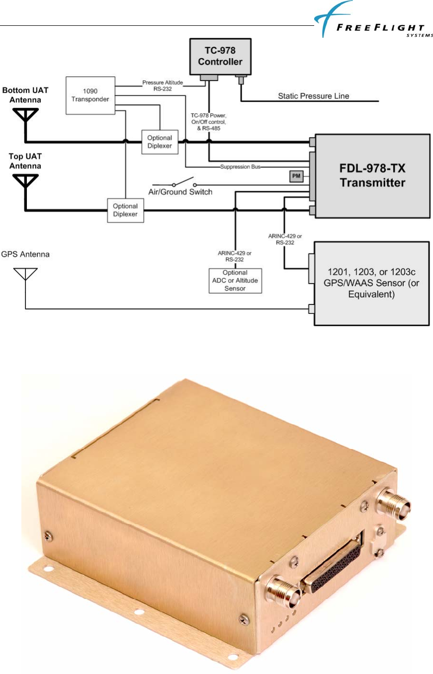
Figure 1 shows a block diagram of a typical FDL-978-TX installation. This installation shows the TC-978
Front Panel Controller, the FDL-978-TX Transmitter, two UAT antennas, a GPS/WAAS sensor, and a GPS
antenna. The GPS sensor can be an existing aircraft GPS source if it meets the interface requirements of the
FDL-978-TX (ARINC 743A (ARINC 429) or FFS Navigation Interface Protocol (RS-232 or RS-422)).
The TC-978 Controller contains an ETSO-C88a certified pressure altitude encoder and a RS-232 serial
output to share the altitude encoder data with other devices such as a transponder. Additionally, an Air Data
System or Pressure Altitude Sensor can optionally be interfaced to the FDL-978-TX to provide pressure
altitude, altitude rate, and true airspeed if it meets the interface requirements of the FDL-978-TX. If an
optional ADS or Altitude Sensor is configured with the FDL-978-TX, the TC-978 Controller will display
the optional sensor altitude and output the optional altitude data on its RS-232 serial output. Note that the
Transponder and the FDL-978-TX must share the same pressure altitude sensor data.
The installation diagram also shows an optional diplexer installation so that antennas can be shared
between a Transponder (1090MHz) and the FDL-978-TX Transmitter. The system can also be installed
with a single UAT antenna in installations where the FAA does not require antenna diversity.
FDL-978-TX ADS-B
Transmitter Installation Manual
86960, Revision A September 1, 2011
I-2
Figure 3. Typical FDL-978-TX Installation
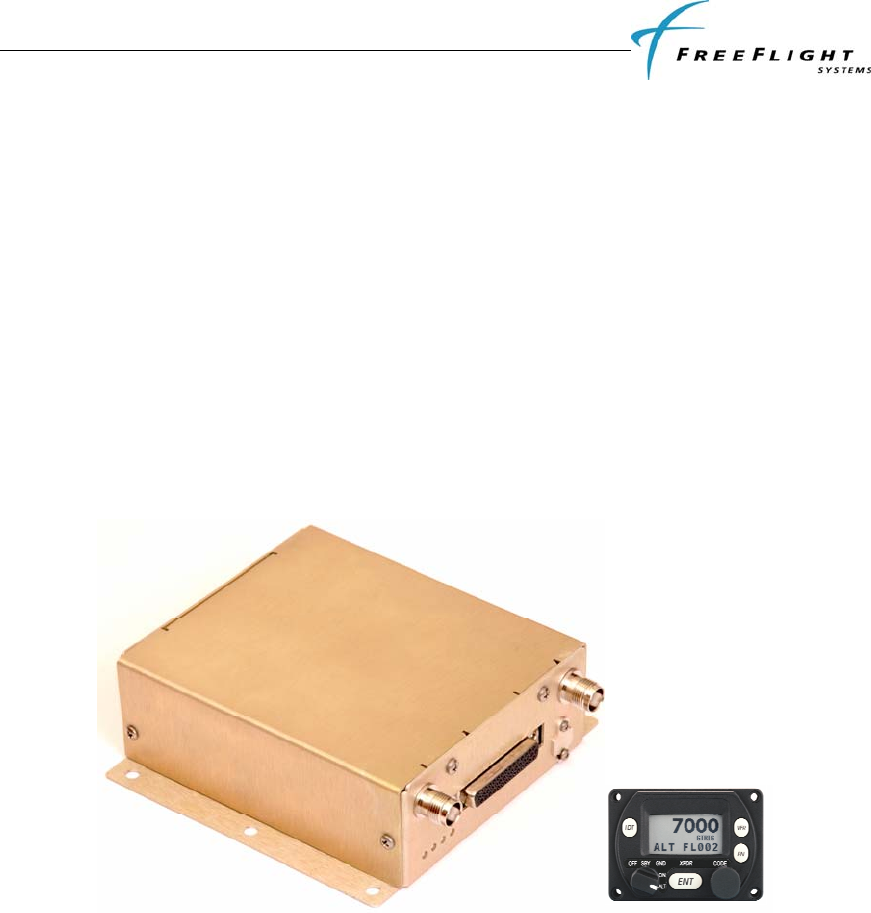
1.2.1 FDL-978-TX Transmitter
FDL-978-TX ADS-B
Transmitter Installation Manual
86960, Revision A September 1, 2011
I-3
Figure 4. FD-978-TX Transmitter
The FDL-978-TX is the main component of the FreeFlight UAT ADS-B Transmitter System. The FDL-
978-TX has a DB-44 female connector, a USB micro-AB maintenance connector, and two TNC UAT
antenna connectors. The FDL-978-TX contains a UAT Transmitter with top and bottom antenna outputs,
four status LEDs, a controller interface, configurable GPS input interface, configurable Air Data/Altitude
input interface, configurable Display output interface, Discrete inputs/outputs, Maintenance interface, and a
Personality Module interface.
A. UAT Transmitter
The transmitter has top and bottom antenna outputs that can be configured to use the top only,
bottom only, or both (diversity).
B. Status LEDs
Four status LEDs (UAT, GPS, UAT TX, and UAT RX(future use)) indicate the operational status
of the FDL-978-TX.
C. Controller Interface
The FDL-978-TX has a TC-978 controller interface that provides low voltage power, system
on/off discrete control, and a communication interface on serial port 3. The system can be
configured through the controller interface.
D. GPS Input
The FDL-978-TX can connect to a FFS navigation protocol GPS (1201) through an RS-232 serial
port or ARINC 743A compatible GPS (1203) through an ARINC 429 bus.
E. Altitude/Air Data Input
The FDL-978-TX can connect to an Altitude/Air Data Sensor through an RS-232 serial port or
ARINC 429 bus and/or output encoded altitude on a serial output.
F. Display Output
The FDL-978-TX can provide ownship traffic data through a RS-232/RS-422 serial port.
G. Discrete Inputs/Outputs
The FDL-978-TX has six discrete inputs and two discrete outputs.
H. Maintenance Interface
The FDL-978-TX has a USB micro-AB serial port connector that can be used to update system
software, check status, test the system, and configure the system.
I. Personality Module Interface
The FDL-978-TX has a personality module interface to retrieve configuration settings if the FDL-
978-TX is replaced in the aircraft.
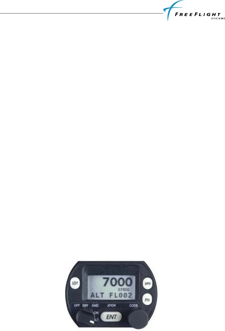
1.2.2 TC-978 Front Panel Controller
Figure 5. TC-978 Controller

FDL-978-TX ADS-B
Transmitter Installation Manual
86960, Revision A September 1, 2011
I-4
The TC-978 Controller is the FDL-978-TX control and status interface. The controller has a DB-9
connector for electrical interface and a static pressure port. The TC-978 contains a LCD display with
controls, a built in Altitude Encoder, low voltage input power interface, FDL-978-TX serial interface,
remote on/off power control, and serial altitude output.
A. Display and Controls
The controller has an LCD status display, an Ident button, a VFR button, FN (function) button,
ENT (enter) button, Mode knob, and Code entry knob.
B. Altitude Encoder
The controller has a built-in altitude encoder to measure pressure altitude.
C. Input Power
The controller receives low-voltage power from the FDL-978-TX.
D. Serial Interface
A two-wire data link is used to connect the TC-978 to the FDL-978-TX.
E. Remote On/Off
System on/off power is controlled with the mode knob.
F. Altitude Output
Pressure altitude data is output on an RS-232 serial port.
1.2.3 UAT Antenna Requirements
The FDL-978-TX requires a TSO-C66, C74, C112, or C154 UHF antenna. Ensure that the antenna is a 50Ω
antenna with a VSWR < 1.7:1 at 978 MHz. The Comant CI-101 and RA Miller AV-22 ball antennas and
the Comant CI-105 blade antenna meet these requirements. In Class B1 ADS-B equipment (TSO-C154c)
installations, antenna diversity (meaning a top and bottom antenna) is required. In Class B1S (single
antenna) installations only one antenna (top or bottom) is used.

FDL-978-TX ADS-B
Transmitter Installation Manual
86960, Revision A September 1, 2011
I-5
1.3 TECHNICAL CHARACTERISTICS
1.3.1 FDL-978-TX Transmitter
FDL-978-TX Transmitter (P/N 85995-00)
ENVIRONMENTAL COMPLIANCE See Appendix
TSO COMPLIANCE C154c (B1/B1S)
FCC IDENTIFICATION
SOFTWARE RTCA/DO-178B Level C
PHYSICAL DIMENSIONS
Height 1.37 in (34.8 mm)
Width 5.0 in (127 mm)
Depth 5.75 in (146.05 mm)
WEIGHT 0.8 lbs (364 g)
OPERATING TEMPERATURE -40°C to +70°C
STORAGE TEMPERATURE -55°C to +85°C
ALTITUDE 50,000 feet
POWER REQUIREMENTS 10 – 40 Volts DC, Typical 0.1 A @ 28 VDC
TRANSMITTER FREQUENCY 978 MHz
TRANSMITTER POWER 40 Watts max at antenna after 3dB connector/cable loses
Avionics Interfaces:
TYPE I/O Description
Controller Input/
Output 7 VDC power output, remote on/off discrete input, RS-485 serial
interface to the TC-978
GPS Input Input Serial (RS-232, RS-422, or RS-485) or ARINC 429 (ARINC
743A) and PPS (RS-422)
ADS/Altitude Input Input Serial (RS-232, RS-422, or RS-485) or ARINC 429
Display Output Output Serial (RS-232, RS-422, or RS-485)
Discrete Inputs Input 6 (Air/Grnd, Anon Mode, CDTI Oper, TCAS RA Active, Traf
Test, & Traf Stdby)
Discrete Outputs Output 2 (Transmit Suppression and UAT Status)

FDL-978-TX ADS-B
Transmitter Installation Manual
86960, Revision A September 1, 2011
I-6
1.3.2 TC-978 Front Panel Controller
TC-978 Controller (P/N 86941)
ENVIRONMENTAL COMPLIANCE See Appendix
TSO COMPLIANCE C154c, C88a
SOFTWARE RTCA/DO-178B Level B
PHYSICAL DIMENSIONS
Height 1.8 in (44 mm)
Width 2.4 in (63 mm)
Depth 2.1 in (54 mm)
WEIGHT .11 lbs (90 g)
OPERATING TEMPERATURE -20°C to +55°C
ALTITUDE 35,000 feet
POWER REQUIREMENTS 5.5 – 10 Volts DC, 0.3A max @ 6.5VDC, powered by FDL-978-
TX
Interfaces:
TYPE I/O Description
Controller Input/
Output 7 VDC power input, remote on/off discrete output, RS-485 serial
interface to the FDL-978-TX
Altitude Output Output RS-232 serial altitude encoder

FDL-978-TX ADS-B
Transmitter Installation Manual
86960, Revision A September 1, 2011
I-7
1.4 PARTS AND EQUIPMENT
1.4.1 FDL-978-TX Transmitter Items
The FDL-978-TX Transmitter and optional installation kit part numbers are listed below:
Part Number Qty Description
85595-XX-XXXX 1 FDL-978-TX Transmitter
85935-00 1 FDL-978-TX Installation Kit
1.4.2 TC-978 Front Panel Controller Items
The TC-978 Controller and optional installation kit part numbers are listed below:
Part Number Qty Description
85941 1 TC-978 Controller
86964-00 1 TC-978 Installation Kit
1.4.3 Installation Kits
The items included in the FDL-978-TX Installation Kit (p/n 85935-00) are listed below:
Part Number Qty Description
86960 1 FDL-978-TX Installation Manual
85945-00-A 1 Personality Module
86945 1 DB-44 Male Crimp Connector
85942 1 DB-44 Backshell
86967 44 Crimp Pin 24-28 AWG
84192 1 DB-9 Female Crimp Connector
84193 1 DB-9 Backshell
84194 9 Crimp Pin female 9-Dsub
16172 1 Double-sided Adhesive Tape
85937 2 Ball UAT Antenna
0129-0017-00 2 TNC Connector
0123-0012-00 50 ft RG-142 Coax Cable
86966 2 BNC RG142 Male Crimp Connector
The items included in the TC-978 Installation Kit (p/n 86964-00) are listed below:
Item Qty Description
1 1 Mounting Adapter (circular hole adapter)
2 1 Static Tubing, EPDM 5mm ID
3 1 Hose T piece
4 2 Hose Adapter
5 6 Hose clip, small
6 2 Hose clip, large
7 4 Long mounting screws, 4-40

FDL-978-TX ADS-B
Transmitter Installation Manual
86960, Revision A September 1, 2011
I-8
8 4 Short mounting screws, 4-40
1.5 MATERIALS REQUIRED BUT NOT SUPPLIED
The following items are required for proper installation but not supplied:
• Wire and shielded wire
• Circuit Breaker
• Ground terminals
• A GPS receiver with appropriate serial or ARINC 743 interface such as the FFS 1201, 1203, or
1203C is required for the ADS-B Transmitter
FDL-978-TX ADS-B
Transmitter Installation Manual
86960, Revision A September 1, 2011
II-1
SECTION II INSTALLATION
2.1 GENERAL
This section provides general information for installing the FDL-978-TX and TC-978 into an aircraft. This
section contains mounting dimensions, pin outs, and interface details pertaining to installation. Adherence
to these installation procedures and information will assure satisfactory system performance.
2.2 UNPACKING AND INSPECTING EQUIPMENT
Exercise care when unpacking each item. Visually inspect each item for evidence of damage incurred
during shipment. If a damage claim must be filed, save the shipping container to substantiate the claim.
When all equipment and the installation kit have been inspected, save the packing material and container in
case the unit is to be stored or reshipped. See paragraph 1.4 for equipment and optional parts supplied.
2.3 EQUIPMENT MOUNTING
2.3.1 TC-978 Mounting
The TC-978 controller must be mounted rigidly in the aircraft panel. The controller can be mounted in the
ultra compact mounting hole or in a conventional 57mm (2¼ inch) instrument cut-out.
The following installation procedure should be followed, remembering to allow adequate space for
installation of cables and connectors.
• Select a position in the panel that is not too close to any high external heat source. (The TC-978 is
not a significant heat source itself).
• Avoid sharp bends and placing the cables too near to the aircraft control cables.
If using a 57mm instrument cut-out, first clip the two mounting adapters to the controller. The controller
should then be mounted using the four LONG screws provided. If using the FFS compact cutout, you do
not need the mounting adapters. The controller should be mounted using the four SHORT screws provided.
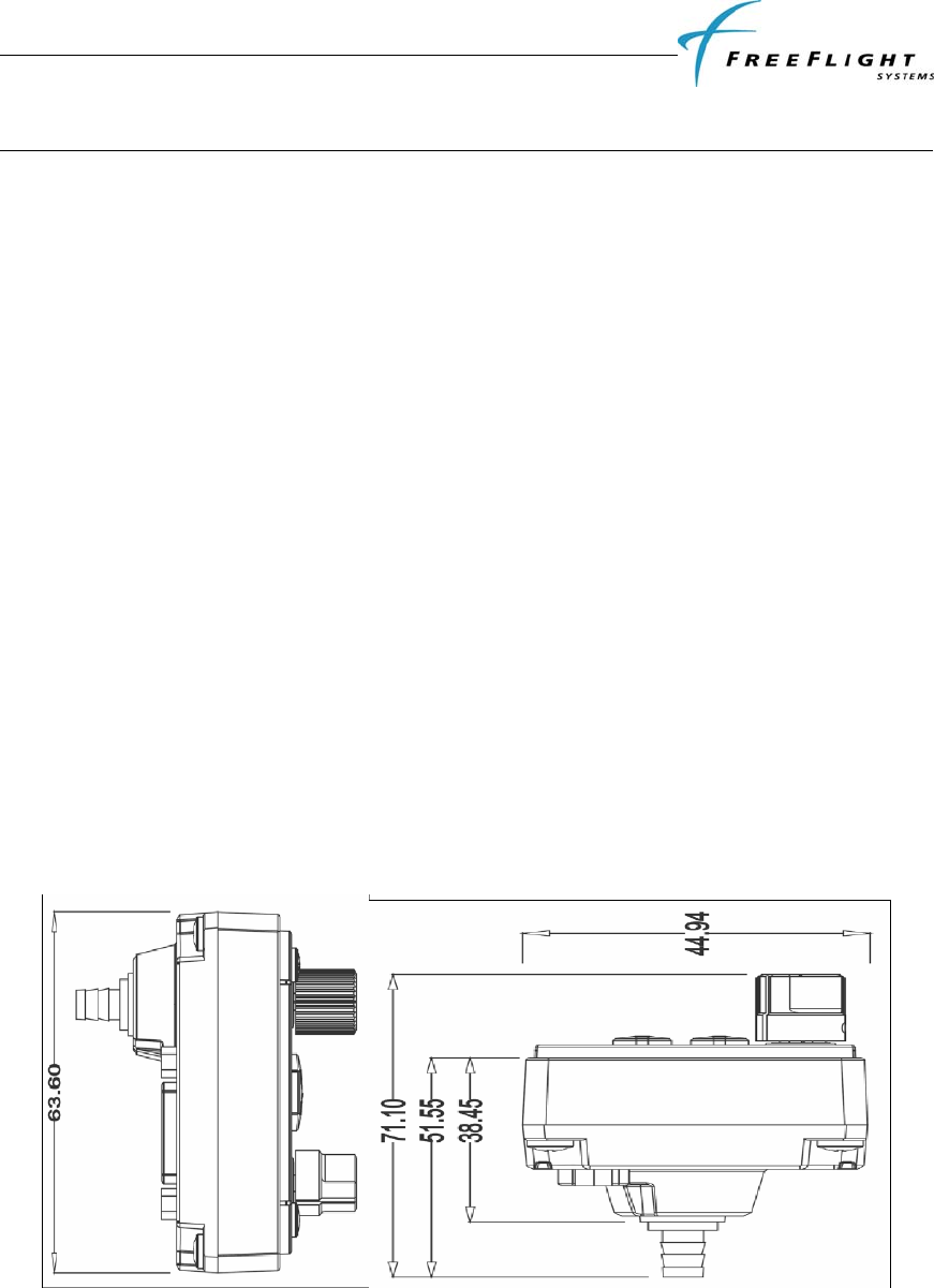
If alternate screws are required, please note that the mounting thread in each case is 4-40.
Figure 6. TC-978-TX Dimensions
2.3.2 FDL-978-TX Mounting
The FDL-978-TX Transmitter is designed to be mounted in any convenient location in the cockpit, the
cabin, or an avionics bay.
FDL-978-TX ADS-B
Transmitter Installation Manual
86960, Revision A September 1, 2011
II-2
The following installation procedure should be followed, remembering to allow adequate space for
installation of cables and connectors.
• Select a position in the aircraft that is not too close to any high external heat source. (The FDL-
978-TX is not a significant heat source itself).
• Avoid sharp bends and placing the cables too near to the aircraft control cables.
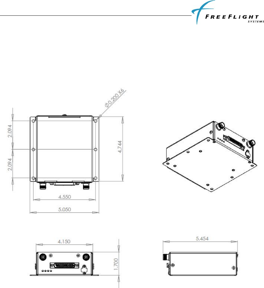
• Secure the FDL-978-TX on a flat surface according to the FDL-978-TX mounting requirements
illustrated below in Figure 7 and in the installation drawing in Appendix D.
Figure 7. FDL-978-TX Mounting Dimensions
2.4 COOLING REQUIREMENTS
The FDL-978-TX and TC-978 meet all TSO requirements without forced air cooling. While each
individual unit does not require forced air cooling, the combined heat load of several units operating in a
typical avionics location may significantly degrade the reliability of avionics if provisions for cooling are
not incorporated in the initial installation. Failure to provide adequate cooling may lead to increased
avionics maintenance costs and may void the FreeFlight Systems Warranty.

FDL-978-TX ADS-B
Transmitter Installation Manual
86960, Revision A September 1, 2011
II-3
2.5 FDL-978-TX UAT ELECTRICAL CONNECTIONS
2.5.1 FDL-978-TX Interface – Pinout
J1 - Power and I/O Connector (DB-44)
PIN SIGNAL ELECTRICAL I/O DESCRIPTION
1 Vin 10-40 VDC Pwr Aircraft Power Input
2 GND Ground Gnd TC-978 Controller Power Return
3 232 RxD2 RS-232 I Serial Port 2 RS-232 Data In
4 TRxD2+ RS-485 I Serial Port 2 RS-422/RS-485 Data+
5 TRxD2- RS-485 I Serial Port 2 RS-422/RS-485 Data-
6 429 IN 2A ARINC 429 I ARINC 429 Input Channel 2A
7 RxD6+ RS-422 I Serial Port 6 Data In+
8 RxD6- RS-422 I Serial Port 6 Data In-
9 SGND4 Serial Ground Gnd Serial Port Ground
10 429 OUT 1A ARINC 429 O ARINC 429 Output Channel 1A
11 429 OUT 1B ARINC 429 O ARINC 429 Output Channel 1B
12 TRAF STDBY Open/Ground I Traffic Standby
13 ANON MODE Open/Ground I Anonymous Mode
14 Vpm 3.0 -3.6 VDC O Personality Module Power Output
15 TRAF TEST Open/Ground I Traffic Test
16 Vin 10-40 VDC Pwr Aircraft Power Input
17 RTRN Ground Gnd Aircraft Power Return
18 Vcp 5.5-10 VDC O TC-978 Controller Power Output
19 SGND2 Serial Ground Gnd Serial Port Ground
20 TRxD3+ RS-485 I/O Serial Port 3 RS-485 Data+
21 TRxD3- RS-485 I/O Serial Port 3 RS-485 Data-
22 GND Gnd Gnd Ground Reference
23 232 RxD3 RS-232 I Serial Port 3 RS-232 Data In (Not used with TC-978)
24 232 TxD3 RS-232 O Serial Port 3 RS-232 Data Out (Not used with TC-978)
25 232 RxD4 RS-232 I Serial Port 4 RS-232 Data In
26 TCAS RA ACT Open/Ground I TCAS Resolution Advisory Active In (Active low)
27 AIR/GRND Open/Ground I Air/Ground In (Squat Switch - configurable)
28 TX SUPPRESS Vin -1.5V O L-Band Suppression Bus
29 Reserved - - -
30 GND Ground Gnd Personality Module Power Return
31 RTRN Ground Gnd Aircraft Power Return
32 REM ON Open/Ground I Remote Power Control (Ground: ON, Open: OFF)
33 232 TxD2 RS-232 O Serial Port 2 RS-232 Data Out
34 429 IN 1A ARINC 429 I ARINC 429 Input Channel 1A
35 429 IN 1B ARINC 429 I ARINC 429 Input Channel 1B
36 429 IN 2B ARINC 429 I ARINC 429 Input Channel 2B
37 TxD6+ RS-422 O Serial Port 6 Data Out+
38 TxD6- RS-422 O Serial Port 6 Data Out-
39 PPS IO+ ARINC 743A I/O Internal/External GPS Pulse Per Second Out/In+
40 PPS IO- ARINC 743A I/O Internal/External GPS Pulse Per Second Out/In-
41 UAT STATUS Open/Ground O ADS-B Status
42 CDTI OPER Open/Ground I CDTI Operational
43 CLK_PM I2C I Personality Module Clock
44 DATA_PM I2C I/O Personality Module Data

FDL-978-TX ADS-B
Transmitter Installation Manual
86960, Revision A September 1, 2011
II-4
2.6 FDL-978-TX UAT INTERFACE DETAILS
2.6.1 Power Input
Aircraft power is provided to the FDL-978-TX through the J1 Power and I/O connector. The power supply
input can be 10 – 40 Volts DC. Use a 2 Amp circuit breaker for power supply protection. Power input
resides on the following pins:
Power Input
PIN SIGNAL ELECTRICAL I/O DESCRIPTION
J1-1 Vin 10-40 VDC Pwr Aircraft Power Input
J1-16 Vin 10-40 VDC Pwr Aircraft Power Input
J1-17 RTRN Ground Gnd Aircraft Power Return
J1-31 RTRN Ground Gnd Aircraft Power Return
2.6.2 Personality Module
Installation specific configuration information is stored in three separate non-volatile memories in a
properly installed system:
• The Personality Module (PM), which is connected to the aircraft connector mated with J1 of the
FDL-978-TX, contains the Master configuration that is used by the FDL-978-TX to configure the
system.
• The TC-978 Controller contains a Back-up configuration that is used by the FDL-978-TX to
configure the system only when the Personality Module is not installed.
• The FDL-978-TX Transmitter contains a Local configuration copy that is used immediately
after power-up to start the system and is synchronized with the PM Master configuration or the
controller Back-up configuration if the PM is not installed.
The Personality Module (PM) eliminates the need to set-up the installation configuration again if a new
FDL-978-TX transmitter or a new TC-978 controller is installed. The Master configuration in the PM is
extracted by the FDL-978-TX and used to update the TC-978 Controller Back-up configuration and FDL-
978-TX Local configuration if different than the PM Master configuration.
The PM should be installed in the aircraft but the system will continue to function correctly if the PM
malfunctions. If the PM malfunctions, the TC-978 Back-up installation configuration will be transferred to
the FDL-978-TX and the FDL-978-TX will update its Local configuration if different. If a new TC-978
controller is installed in a system with a malfunctioning PM then the configuration information must be re-
configured.
The PM has no lightning protection so the wire length between the PM and the Power and I/O connector
must be less than 4”. The PM connection is on the following pins:
Personality Module Interface
PIN SIGNAL ELECTRICAL I/O DESCRIPTION
J1-14 Vpm 3.0 -3.6 VDC O Personality Module Power Output
J1-30 GND Ground Gnd Personality Module Power Return
J1-43 CLK_PM I2C I Personality Module Clock
J1-44 DATA_PM I2C I/O Personality Module Data

FDL-978-TX ADS-B
Transmitter Installation Manual
86960, Revision A September 1, 2011
II-5
2.6.3 Status LEDs
Four external LEDs on the front of the enclosure indicate system status to the installer. The following table
describes the LED states that can be observed:
NAME DESCRIPTION
STATUS UAT System Status (RED)
ON UAT failure. Troubleshoot system.
OFF UAT is operating normally.
GPS GPS Status (GREEN)
Flashing GPS is acquiring satellites and determining position.
ON GPS has acquired satellites and is operating normally.
OFF GPS is not communicating or has failed.
TX UAT Transmit (GREEN)
Blink ON Blinks ON when ADS-B data is transmitted (once per second)
OFF No UAT transmissions
RX UAT Receive (GREEN)
OFF No UAT receptions (UAT transmitter has no receiver so this is the
normal condition)
2.6.4 Controller Interface
Low voltage power (+7 Volts DC), a system ON/OFF discrete control, and serial communication (RS-485
or RS-232) on serial port 3 is provided through the J1 Power and I/O connector as the controller interface.
Serial port 3 is a single communication port that can be electrically interfaced via RS-232 or RS-485. For
the current FDL-978-TX this interface is intended for use with the TC-978 Controller. The TC-978
Controller uses the serial port 3 RS-485 pins (J1-20 & J1-28) and does not use serial port 3 RS-232 pins
(J1-23 & J1-24). Future controllers may use the serial port 3 RS-232 pin interface rather than the RS-485
interface.
The controller interface connections are as follows:
Controller Interface
PIN SIGNAL ELECTRICAL I/O DESCRIPTION
J1-18 Vcp +7 VDC O TC-978 Controller Power Output
J1-2 GND Ground Gnd TC-978 Controller Power Return
J1-32 REM ON Open/Ground I Remote Power Control (Ground: ON, Open: OFF)
J1-20 TRxD3+ RS-485 I/O Serial Port 3 RS-485 Data+
J1-21 TRxD3- RS-485 I/O Serial Port 3 RS-485 Data-
J1-23 232 RxD3 RS-232 I Serial Port 3 RS-232 Data In (Not used with TC-978)
J1-24 232 TxD3 RS-232 O Serial Port 3 RS-232 Data Out (Not used with TC-978)
2.6.5 Physical Serial Interfaces
There are a total of five physical serial interfaces available on the FDL-978-TX: Three UART style Serial
Port interfaces and two ARINC 429 Input interfaces. These physical serial interfaces are available for
connecting to four different functional interfaces:
• GPS Input
o Serial Port: “GPS-FreeFlight” or

FDL-978-TX ADS-B
Transmitter Installation Manual
86960, Revision A September 1, 2011
II-6
o ARINC: “GPS”
• Altitude/Air Data Input
o Serial Port: “Altitude Encoder” or “ADC”
o ARINC: “ADC”
• Altitude Encoder Output
o Serial Port: “Encoded Altitude”
• Display Output
o Serial Port: “TIS/FIS” or “ADS-B Pass Thru”
Each of the four functional interfaces can be configured to one and only one physical serial interface. Only
one of each of the functional interfaces is handled by the FDL-978-TX All physical serial interfaces are
configured to functional interfaces in Configuration Mode. If two or more physical serial interfaces are
configured to the same functional interface only one physical serial interface is programmed by the FDL-
978-TX to use the functional interface and all other configurations of the same functional interface are
ignored. The order of precedence used by the FDL-978-TX for a functional interface is as follows:
• ARINC 429 physical interface takes precedence over UART physical interface
• Lowest port/channel number takes precedence over higher port/channel number
For example, if Serial Port 2 Input is configured to “GPS-FreeFlight” and ARINC 429 Input Channel 1 is
configured to “GPS” then the FDL-978-TX uses ARINC 429 Input Channel 1 as the GPS Input functional
interface and the Serial Port 2 Input configuration is ignored. As another example, if ARINC 429 Input
Channel 2 and ARINC 429 Input Channel 1 are both configured to “GPS” then the FDL-978-TX uses
ARINC 429 Input Channel 1 for the GPS Input functional interface and the ARINC 429 Input Channel 2
configuration is ignored.
Additionally, only one functional interface type can be configured for each of the two UART style Serial
Port (2 & 6) physical serial interfaces that have bi-directional capability. If both the input and the output of
Serial Port 2 or 6 are configured then the order of precedence is as follows:
• GPS Input
• Altitude/Air Data Input
• Altitude Encoder Output
• Display Output
For example, if Serial Port 2 Input is configured to ”GPS-FreeFlight” and Serial Port 2 Output is
configured to “TIS/FIS” then the FDL-978-TX uses Serial Port 2 as the GPS Input functional interface and
the Serial Port 2 Output configuration is ignored.
2.6.5.1 Serial Ports - RS-232 / RS-422 / RS-485
Three UART style (Serial Port) physical serial interfaces are available on the FDL-978-TX. The three
Serial Ports available are described below:
• Serial Port 2 – Bi-directional (transmit and receive) capability and can interface via either RS-232
or RS-485. Typically configured as the GPS Input functional interface but can also be configured
as a Display Output, Altitude/Air Data Input, Altitude Encoder Output
• Serial Port 4 – RS-232 receive-only capability. Typically configured as the Altitude/Air Data
Input functional interface but can also be configured as a GPS Input.
• Serial Port 6 – RS-422 bi-directional (transmit and receive) capability. Typically configured as the
Display Output functional interface but can also be configured as a GPS Input, Altitude/Air Data
Input, or Altitude Encoder Output.

FDL-978-TX ADS-B
Transmitter Installation Manual
86960, Revision A September 1, 2011
II-7
The UART style physical serial interface pin connections are as follows:
Serial Ports
PIN SIGNAL ELECTRICAL I/O DESCRIPTION
J1-3 232 RxD2 RS-232 I Serial Port 2 RS-232 Data In
J1-33 232 TxD2 RS-232 O Serial Port 2 RS-232 Data Out
J1-19 SGND2 Serial Ground Gnd Serial Port Ground
J1-4 TRxD2+ RS-485 I Serial Port 2 RS-422/RS-485 Data+
J1-5 TRxD2- RS-485 I Serial Port 2 RS-422/RS-485 Data-
J1-25 232 RxD4 RS-232 I Serial Port 4 RS-232 Data In
J1-9 SGND4 Serial Ground Gnd Serial Port Ground
J1-7 RxD6+ RS-422 I Serial Port 6 Data In+
J1-8 RxD6- RS-422 I Serial Port 6 Data In-
J1-37 TxD6+ RS-422 O Serial Port 6 Data Out+
J1-38 TxD6- RS-422 O Serial Port 6 Data Out-
2.6.5.2 ARINC 429 Channels
Two ARINC 429 Input physical serial interfaces are available on the FDL-978-TX. The ARINC 429 Input
channels are 429 IN 1 and 429 IN 2. The FDL-978-TX has one ARINC 429 Output that is reserved for
future use and is not currently configurable. Both ARINC channels can be configured as either high-speed
or low-speed. The ARINC output channel is reserved for future use.
The ARINC 429 Input channels can be configured as either of the following:
• Air Data Computer Input – accepts the following ARINC labels:
LABEL DESCRIPTION
203 Pressure Altitude
210 Airspeed
212 Altitude Rate
• GPS Input – accepts the following ARINC 743A labels:
LABEL DESCRIPTION
110 Latitude Coarse
120 Latitude Fine
111 Longitude Coarse
121 Longitude Fine
370 Altitude (HAE)
166 North/South Velocity
174 East/West Velocity
112 Groundspeed
103 True Track Angle
165 Vertical Speed
260 Date
150 UTC
130 Horizontal Integrity Limit (HIL)
133 Vertical integrity Limit (VIL)
247 Horizontal Figure of Merit (HFOM)
136 Vertical Figure of Merit (VFOM)
273 Sensor Status

FDL-978-TX ADS-B
Transmitter Installation Manual
86960, Revision A September 1, 2011
II-8
The ARINC 429 physical serial interface pin connections are as follows:
ARINC 429 Ports
PIN SIGNAL ELECTRICAL I/O DESCRIPTION
J1-34 429 IN 1A ARINC 429 I ARINC 429 Input Channel 1A
J1-35 429 IN 1B ARINC 429 I ARINC 429 Input Channel 1B
J1-6 429 IN 2A ARINC 429 I ARINC 429 Input Channel 2A
J1-36 429 IN 2B ARINC 429 I ARINC 429 Input Channel 2B
J1-10 429 OUT 1A ARINC 429 O ARINC 429 Output Channel 1A
J1-11 429 OUT 1B ARINC 429 O ARINC 429 Output Channel 1B
2.6.6 Discrete Inputs
Six discrete inputs are available on the FDL-978-TX for specific purposes (current or future). All six
discrete inputs are intended to be connected to open/ground type switches if used. All discrete inputs
default to the open condition if not connected. The discrete input pin connections are as follows:
Discrete Inputs
PIN SIGNAL ELECTRICAL I/O DESCRIPTION
J1-12 TRAF STDBY Open/Ground I Traffic Standby
J1-13 ANON MODE Open/Ground I Anonymous Mode
J1-15 TRAF TEST Open/Ground I Traffic Test
J1-22 GND Ground Gnd Ground Reference
J1-26 TCAS RA ACT Open/Ground I TCAS Resolution Advisory Active In (Active low)
J1-27 AIR/GRND Open/Ground I Air/Ground In (Squat Switch - configurable)
J1-42 CDTI OPER Open/Ground I CDTI Operational
2.6.6.1 Air/Ground Input
The Air/Ground discrete input can be connected to an open/ground squat switch or other Air/Ground
discrete indication. The Air/Ground discrete is configurable to be either Not Connected, High when
Airborne, or Low (ground) when Airborne. The FDL-978-TX automatically determines air/ground state
based on several factors: Emitter Category type, Airspeed (if available), groundspeed, and Air/Ground
discrete input.
2.6.6.2 Anonymous Mode Input
The anonymous mode discrete input determines if the FDL-978-TX is in anonymous address mode. If the
anonymous mode input is tied to ground the FDL-78-TX will be in anonymous mode and transmit a
randomly generated anonymous address in the ADS-B message in place of the ICAO address. Even if
anonymous mode is set, the FDL-978-TX will transmit the configured Mode S (ICAO) address under the
following conditions:
• During the first two minutes after initial power-up
• When the squawk code is set to anything other than 1200
2.6.6.3 CDTI Operational Input
The CDTI Operational Input is reserved for future use to indicate the operational status of an on-board
TCAS. A ground will indicate the TCAS is installed and operational, while an open will indicate the TCAS
is not installed or operational. This discrete should be left open.
2.6.6.4 TCAS Resolution Advisory Active Input
The TCAS Resolution Advisory Active Input is reserved for future use to indicate the status of any
resolution advisories from an on-board TCAS. A ground will indicate a TCAS resolution advisory is active,
while an open will indicate no TCAS resolution advisories are active. This discrete should be left open.

FDL-978-TX ADS-B
Transmitter Installation Manual
86960, Revision A September 1, 2011
II-9
2.6.6.5 Traffic Standby Input
The Traffic Standby Input is reserved for future use to indicate the traffic standby status of a 429 traffic
display. This discrete should be left open.
2.6.6.6 Traffic Test Input
The Traffic Test Input is reserved for future use to indicate the traffic test status of a 429 traffic display.
This discrete should be left open.
2.6.7 Discrete Output
Two discrete outputs are available to provide UAT status and operational information to other equipment.
The two discrete output connection pins are as follows:
Discrete Outputs
PIN SIGNAL ELECTRICAL I/O DESCRIPTION
J1-28 TX SUPPRESS Vin -1.5V O L-Band Suppression Bus
J1-41 UAT STATUS Open/Ground O ADS-B Status
2.6.7.1 UAT Status Output
The UAT Status output is an active low, open collector output capable of sinking a maximum of 100 mA.
The UAT status output indicates a UAT system failure when grounded. Note that UAT system failure
includes the loss of valid GPS data from the external GPS.
2.6.8 TX Suppression Output
The TX Suppress output is for suppressing other L-band equipment during UAT transmissions. TX
Suppress outputs a high (Vin – 1.5 V) only during UAT ADS-B message transmissions and is low
otherwise. The TX Suppress output is typically connected to the transponder suppression bus.
2.6.9 Time Mark Input (PPS)
The Time Mark Input is an RS-422 differential pair for the one pulse-per-second (PPS) input from a GPS
like the FFS 1201 or FFS 1203/1203C. The Time Mark input from a GPS provides the timing
synchronization for sending ADS-B messages. The Time Mark input pin connections are as follows:
Time Mark Input
PIN SIGNAL ELECTRICAL I/O DESCRIPTION
J1-39 PPS IO+ ARINC 743A I/O Internal/External GPS Pulse Per Second Out/In+
J1-40 PPS IO- ARINC 743A I/O Internal/External GPS Pulse Per Second Out/In-
2.6.10 Maintenance Interface
The Maintenance interface is used to communicate with a PC using a special Maintenance Interface Cable
(p/n 85595-00-TC) from FreeFlight Systems. This interface can be used to configure the system, provide
additional status information, and update system software. The Maintenance interface is reserved for use by
qualified FreeFlight Systems personnel. The Maintenance interface pin connections are as follows:
J4 – Maintenance Port (USB Micro-AB)
PIN SIGNAL ELECTRICAL I/O DESCRIPTION
J4-1 VBUS +5V DC O +5V DC Power Out
J4-2 TTL RxD5 TTL Serial I Serial Port 5 TTL (3.3V) Data In
J4-3 TTL TxD5 TTL Serial O Serial Port 5 TTL (3.3V) Data Out
J4-4 SERVICE ID Open/Ground I Maintenance Control (Ground: ON, Open: DISABLED)

FDL-978-TX ADS-B
Transmitter Installation Manual
86960, Revision A September 1, 2011
II-10
J4-5 GND Ground Gnd Ground Reference / Power Return

FDL-978-TX ADS-B
Transmitter Installation Manual
86960, Revision A September 1, 2011
II-11
2.7 TC-978 CONTROLLER ELECTRICAL CONNECTIONS
2.7.1 TC-978 Connection – Pinout
TC-978 Connections (DB-9)
PIN SIGNAL ELECTRICAL I/O DESCRIPTION
1 GND Ground Gnd Signal Common
2 TMAPA RS-485 I/O Controller Serial Bus (+)
3 TMAPB RS-485 I/O Controller Serial Bus (-)
4 ALT_OUT RS-232 O Pressure Altitude Out
5 Reserved - - -
6 GND Ground Gnd Signal Common
7 REM ON Open/Gnd O Remote Power Control (Ground: ON, Open: OFF)
8 POWER 6 – 10 VDC Pwr Controller Power
9 CLK_PM Ground Gnd Controller Power Common
2.8 TC-978 CONTROLLER INTERFACE DETAILS
2.8.1 Power
The TC-978 uses 5.5 – 10 volts from the FDL-978-TX (typically ~7 volts). Do NOT connect to aircraft
input power.
2.8.2 Remote ON
The Remote ON output controls the ON/OFF power to the FDL-978-TX. This output is connected directly
to the Power/Mode switch on the TC-978 and should be connected to the REM ON input (J1-32) of the
FDL-978-TX.
2.8.3 TMAP Bus
TMAP is a proprietary bus using RS-485 serial communication. TMAP is a bi-directional interface between
the TC-978 and the FDL-978-TX. The TMAP differential lines (TMAPA & TMAPB) on the TC-978 must
be connected to the corresponding differential lines (TRxD3+ and TRxD3-) on the FDL-978-TX.
2.8.4 Altitude Out
The TC-978 outputs pressure altitude data on this RS-232 serial output pin (ALT_OUT) at 9600 baud using
the commonly called “Icarus” format. The pressure altitude data that is output depends on the Altitude
input configuration. If an Altitude/Air Data functional interface is configured on a FDL-978-TX physical
interface, then the pressure altitude data output will be from the configured interface. If no Altitude/Air
Data functional interface is configured, then the pressure output defaults to the TC-978 built-in altitude
encoder. This output should feed the transponder so they share the same altitude source unless the altitude
sensor has multiple outputs to feed both the FDL-978-TX and the transponder.
2.9 PERSONALITY MODULE INSTALLATION
The Personality Module is intended to be installed inside the DB-44 connector backshell of the cable
harness in the aircraft. The Personality Module allows the FDL-978-TX and the TC-978 to be removed and
replaced without having to re-configure the system.
The following install kit parts from the FDL-978-TX install kit (p/n 85935-00) are used to install the
personality module in the backshell:
Item Qty Description
FDL-978-TX ADS-B
Transmitter Installation Manual
86960, Revision A September 1, 2011
II-12
1 1 Personality Module (p/n 85945-00-A)
2 4 Pin Contact, Crimp (p/n 86967)
3 1 Double-sided Adhesive Tape (p/n 16172)
The following table shows the Personality Module (PM) wire color connections to the DB-44 connector:
Personality Module Interface
DB-44
PIN SIGNAL ELECTRICAL I/O DESCRIPTION PM WIRE COLOR
J1-14 Vpm 3.0 -3.6 VDC O Personality Module Power Red
J1-30 GND Ground Gnd Personality Module Power Return Black
J1-43 CLK_PM I2C I Personality Module Clock Blue
J1-44 DATA_PM I2C I/O Personality Module Data White
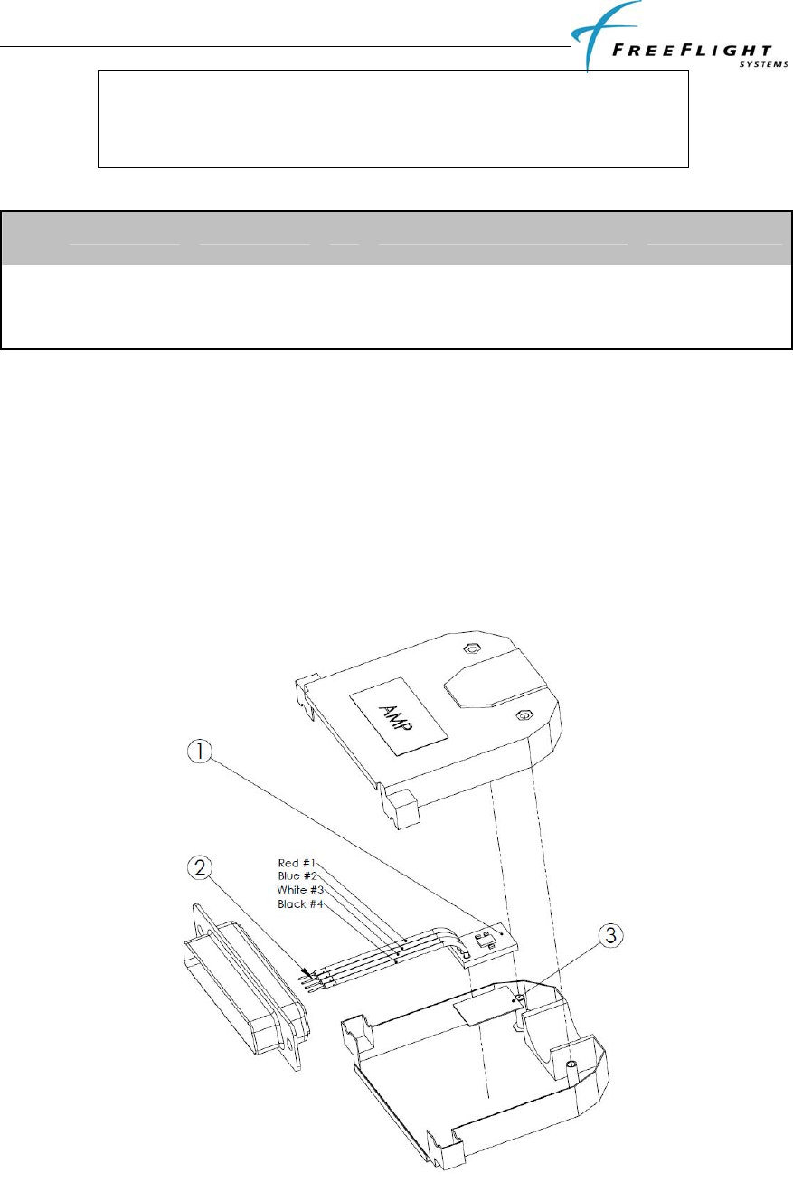
The Personality Module should be assembled into the backshell of the DB-44 male connector in the aircraft
wiring harness as follows:
1. Strip 1/8” of the insulation from each of the four wires of the Personality Module.
2. Crimp pin contacts onto each of the four wire of the Personality module.
3. Insert crimped pins into the DB-44 connector housing according to the table above.
4. Adhere one side of the double-sided tape pad to the Personality Module as shown in Figure 8 and
the other side should be adhered to one side of the connector backshell as the connector and
backshell are assembled together.
Figure 8. Personality Module Assembly

FDL-978-TX ADS-B
Transmitter Installation Manual
86960, Revision A September 1, 2011
II-13
2.10 WIRING CONSIDERATIONS
The connection from the FDL-978-TX transmitter to the TC-978 controller uses a minimum of six (6)
signal lines; the TMAP pair, the Power and Ground pair, and the Remote On discrete line plus associated
ground line. In a certified installation, MIL-W-16878E/4 or equivalent wire should be used. Wire gauge
should be 24 AWG for all wires. Shielded, twisted wiring is recommended for the TMAP pair (and all
serial data communication pairs) to improved electromagnetic emissions and susceptibility – one twist per
1 to 2 inches is adequate. Other pairs in the bundle can also be twisted but are not required.
The distance between the FDL-978-TX transmitter and the TC-978 controller is limited by the impedance
of the wire between them. The TC-978 is powered from the FDL-978-TX, not from aircraft power, and
therefore the acceptable voltage drop in the power line limits the wire length. The TC-978 needs an
impedance of less than 1.0 ohm in the power line for satisfactory operation. The following table gives
guidelines for typical aircraft hook-up wire. Note that different brands may vary – check your supplier for
details.
GAUGE MILIOHM/FT LENGTH FOR 0.5 OHM
24 AWG 30.2 33.2 ft
An alternative to a harness built from individual wires, particularly for a long cable run, is to use a multi-
core cable. Aviation grade cable with 6 or more cores is often more expensive than the individual wires.
Note that not all data cable is suitable for this application. Cables with solid cores should not be used, and
cables should be selected based on the wear characteristics of their insulation material, including
temperature rating, resistance to solvents and oils, and flammability. Most inexpensive commercial data
cables have poor flammability properties.
2.11 UAT ANTENNA INSTALLATION
The antenna should be installed according to the manufacturer’s instructions.
Selecting appropriate UAT antenna locations is critical to the proper performance of the FDL-978-TX. The
following considerations should be taken into account when selecting the Antenna location.
• The antennas should be well removed from any projections, the engine(s) and propeller(s). It
should also be well removed from landing gear doors, access doors or others openings which will
break the ground plane for the antenna.
• The antenna should be mounted on the bottom and or top surface of the aircraft and in a vertical
position when the aircraft is in level flight.
• Avoid mounting the antenna within 3 feet of the ADF sense antenna or any COMM antenna and 6
feet from the transponder and DME antennas.
• Where practical, plan the antenna location to keep the cable lengths as short as possible and avoid
sharp bends in the cable to minimize the VSWR.
Electrical connection to the antenna should be protected to avoid loss of efficiency as a result of the
presence of liquids or moisture. All antenna feeders shall be installed in such a way that a minimum of RF
energy is radiated inside the aircraft.
2.11.1 UAT Antenna Ground Plane
When a conventional aircraft monopole antenna is used it relies on a ground plane for correct operation.
For ideal performance the ground plane should be very large compared to the wavelength of the
transmission, which is ~12in. In a metal skinned aircraft this is usually easy to accomplish, but is more
difficult in a composite or fabric skinned aircraft. In these cases a metallic ground plane should be
fabricated and fitted under the antenna.

FDL-978-TX ADS-B
Transmitter Installation Manual
86960, Revision A September 1, 2011
II-14
As the ground plane is made smaller, the actual dimensions of the ground plane become more critical, and
small multiples of the wavelength should be avoided, as should circles. Rectangles or squares are much less
likely to create a critical dimension that resonates with the transmissions. The smallest practical ground
plane is a square around 5.25 in per side; as the size increases the performance may actually get worse, but
will be better by the time the ground plane is 30.5 in on each side. Anything much larger than that size is
unlikely to show significant further improvement.
The thickness of the material used to construct the ground plane is not critical, providing it is sufficiently
conductive. A variety of proprietary mesh and grid solutions are available.
2.11.2 UAT Antenna Cable
The FDL-978-TX is designed to meet Class B1/B1S requirements with an allowance of 2.5 – 6.5 dB for
loss in the connectors and cable used to connect it to the antenna. Excessive loss degrades transmitter
output power so it is recommended that the installation cable loss be limited to the loss minimum of 2.5dB.
Allowing 0.25dB loss for the connector at each end of the antenna cable assembly leaves an allowance of
2.0 – 6.0 dB loss for the cable itself.
An acceptable cable then has:
• A minimum of 2.0dB loss for the run length but no greater than 6.0dB loss
• A characteristic impedance of 50 Ohms
• Double braid screens or has a foil and braid screen
Once the cable run length is determined, a cable type with the proper attenuation (loss) per foot that meets
the above requirements can be chosen. Longer runs require lower loss cable. Consider moving the FDL-
978-TX closer to the antenna to minimize the losses in the antenna cable subject to the limits identified
above.
The following table is a guide to the minimum and maximum usable lengths of some common cable types.
Actual cable loss varies between manufacturers and the table is based on typical data. Use the table as a
guide only and refer to the manufacturer’s data sheet for the specific cable chosen to calculate the minimum
and maximum lengths.
CABLE ATTENUATION
(dB/100 ft @ 1 GHz)
MIN LENGTH
(ft) MAX LENGTH
(ft)
RG-174 27.1 7.4 22.1
RG-316 25.8 7.75 23.25
RG-400 14.5 13.8 41.3
RG-142 12.8 15.6 46.9
RG-393 7.5 26.7 80
When routing the cable, ensure the following:
• Route the cable away from sources of heat.
• Route the cable away from potential interference sources such as ignition wiring, 400Hz
generators, fluorescent lighting, and electric motors.
• Allow a minimum separation of 12 inches (300mm) from an ADF antenna cable.
• Keep the cable run as short as possible.
• Avoid routing the cable around tight bends.
• Avoid kinking the cable even temporarily during installation.
• Secure the cable so that it cannot interfere with other systems.
FDL-978-TX ADS-B
Transmitter Installation Manual
86960, Revision A September 1, 2011
II-15
2.12 STATIC PRESSURE CONNECTION
The TC-978 controller includes an altitude encoder which must be connected to the same source of static
pressure as the primary altimeter on the aircraft. The TC-978 static pressure port provides a mounting
spigot intended for nominal 5mm or 3/16 inch inside diameter tubing. A length of 5mm EPDM rubber
tubing is included in the installation kit to facilitate connection to the aircraft static system.
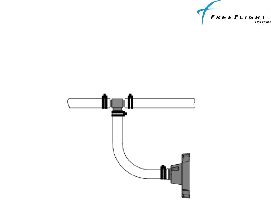
Choose a point in the existing static pressure line that is as close as practical to the TC-978. Cut the static
pressure line, and use the supplied T fitting to connect the altitude encoder. Take care not to contaminate
the inside of the static line when cutting or inserting the connectors.
The following diagram shows the general arrangement, although other combinations may be used:
For aircraft with ¼ inch static lines, two adapters are provided which can convert from ¼ inch inside
diameter hoses to the 5 mm hose in the install kit.
In all cases, the static line should include drainage provisions and should be routed in accordance with CS
23.1325 or other applicable airworthiness provisions for the aircraft.
2.13 EQUIPMENT LIMITATIONS
For a compliant installation in accordance with the Technical Standard Order (TSO) and the Federal
Aviation Regulations (FAR), the FDL-978-TX installation must meet the following requirements:
“The conditions and tests required for TSO approval of this article are minimum performance
standards. It is the responsibility of those desiring to install this article, either on or within a
specific type or class of aircraft, to determine that the article, when installed, performs in
accordance with the design specifications that meet this TSO. The article may be installed only if
further evaluation by the applicant documents an acceptable installation and is approved by the
Administrator.”
The antenna installation must comply with the specifications in Section 2.11.
FDL-978-TX ADS-B
Transmitter Installation Manual
86960, Revision A September 1, 2011
III-1
SECTION III CONFIGURATION AND CHECKOUT
3.1 GENERAL
This section contains installation configuration, checkout, and basic operating procedures. More detailed
operating procedures are contained in the Pilot Guide.
3.1.1 Continued Airworthiness Requirements
The FreeFlight FDL-978-TX and TC-978 requires no periodic maintenance or calibration. Maintenance is
performed on an on-condition basis only. The FreeFlight FDL-978-TX does a power on self test (POST)
and is continually tested periodically using a Built-In Test (PBIT) when the system is in operation. This
method of testing will notify the operator of a failure. System software updates are accomplished using the
Maintenance Interface.
3.1.2 Normal Controller Operation
The FDL-978-TX interfaces to a TC-978 Front Panel Controller used in-flight by the pilot to control output
of ADS-B messages. The TC-978 receives its power from the FDL-978-TX and communicates to the FDL-
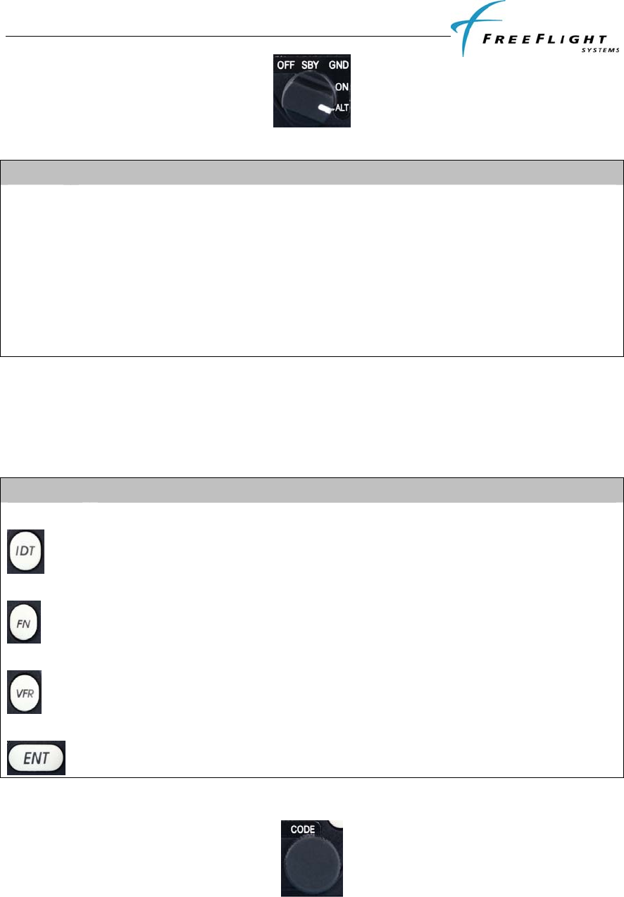
978-TX through a RS-485 serial port. The TC-978 has a monochrome LCD display flanked by a rotary
mode selector knob (OFF, SBY, GND, ON, and ALT) and a continuously rotating knob used for code and
data entry.
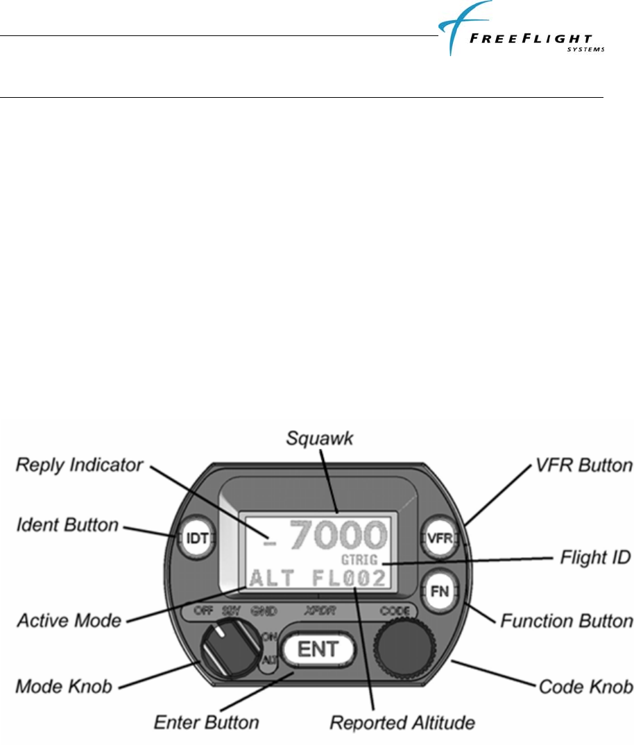
3.1.2.1 Display
The display shows the operating mode of the FDL-978-TX, the reported pressure altitude, and the current
squawk code and Flight ID. The reply indicator is active when the FDL-978-TX transmits ADS-B
messages.
The pressure altitude is displayed as a Flight Level, which is the pressure altitude in hundreds of feet. When
non-standard atmospheric conditions apply this may not match the altimeter indicated altitude but will be
correctly reported in the ADS-B message.
3.1.2.2 Mode Selector Knob
The left hand Mode knob controls the power to the FDL-978-TX and the operating mode.
FDL-978-TX ADS-B
Transmitter Installation Manual
86960, Revision A September 1, 2011
III-2
The knob rotates between the different operating modes as defined in the table below:
POS DESCRIPTION
OFF Power is removed from the FDL-978-TX.
SBY The FDL-978-TX is on but will not transmit any ADS-B messages.
GND The FDL-978-TX is in normal transmission Mode and reports pressure altitude in ADS-B
message if available. (Same as ALT setting)
ON The FDL-978-TX is placed in pressure altitude transmission inhibit Mode. Pressure altitude
reporting in ADS-B message is suppressed.
ALT The FDL-978-TX is in normal transmission Mode and reports pressure altitude in ADS-B
message if available. (Same as GND setting)
When airborne the controller should always be set to ALT unless otherwise directed by
Air Traffic Control. Aircraft installations should include a ground indication squat switch
to automatically transmit ADS-B ground messages upon landing.
3.1.2.3 Push Buttons
BUTTON DESCRIPTION
IDT
Press the IDT button when ATC instructs you to “Ident” or “Squawk Ident”.
FN
Pressing the FN button provides access to changing the Flight ID, displaying warnings, and
checking reported GPS position.
VFR
Pressing the VFR button sets the ADS-B to the pre-programmed conspicuity code. Pressing
the button again restores the previous squawk code.
ENT
The ENT button enters a digit in the code selector.
3.1.2.4 Code Selector Knob
The right hand knob is used to set squawk codes and the Flight ID. The FN button selects which will be
updated. Turning the knob will highlight the first digit on the display, and the digit can be changed as
required. Press the ENT button to advance to the next digit. When ENT is pressed on the last digit, the new

FDL-978-TX ADS-B
Transmitter Installation Manual
86960, Revision A September 1, 2011
III-3
squawk code or Flight ID will replace the previous value. If the code entry is not completed within 7
seconds the changes are ignored and the previous code restored.
CODE DESCRIPTION
1200 VFR code in the USA
7000 VFR code commonly used in Europe.
7500 Hijack code
7600 Loss of communications
7700 Emergency code
The Flight ID should correspond to the aircraft call sign entered on flight plan. If no flight plan is active the
aircraft registration should be used as the Flight ID. Use only letters and digits. If the Flight ID is less than
8 characters long entering a blank character will end it.
3.1.2.5 Warning Messages
If the FDL-978-TX detects a problem the screen will indicate WARNING with a brief statement of the
problem. Depending on the nature of the problem the FDL-978-TX may not be transmitting ADS-B
messages. Press ENT to clear the message. If the fault is still present the message will reappear.
3.1.2.6 Fault Annunciation
If the transponder detects a catastrophic internal failure the screen will indicate FAULT with a brief
statement of the problem. No ADS-B messages will be transmitted when a fault has been detected.

FDL-978-TX ADS-B
Transmitter Installation Manual
86960, Revision A September 1, 2011
III-4
3.2 PRELIMINARY CHECKOUT
Before the unit is installed and tested, verify that all cables are properly secured. With the FDL-978-TX and
TC-978 removed, turn on the power and verify the following:
1. Verify that Aircraft DC bus voltage is present on pins 1 and 16 of P1.
2. Verify that ground is present on pins 17 and 31 of P1.
3. Verify that the two UAT antenna coax center conductors are not shorted to its shield or aircraft
ground.
When the above conditions are verified, turn off the master power. Properly attach the external connectors
to the FDL-978-TX and TC-978. Mount the TC-978 in there respective mounting locations. Turn on master
power and then turn on the TC-978. During initialization the FDL-978-TX unit performs a comprehensive
diagnostics test. A failure of a system component will be annunciated by a "Warning Indication" on the TC-
978. Warnings concerning the GPS status may not be displayed until 2.5 minutes after power on in order to
give the GPS time to acquire satellites. Consult the Pilot Guide for more information concerning
WARNING messages.

FDL-978-TX ADS-B
Transmitter Installation Manual
86960, Revision A September 1, 2011
III-5
3.3 INSTALLATION SETUP AND CONFIGURATION
The TC-978 Controller is used in a special configuration mode to program important system installation
parameters and is described in the following paragraphs.
3.3.1 Configuration Item Summary
CONFIGURATION ITEM DEFAULT SETTING
Mode S Address (ICAO) 0
VFR Squawk Code 1200
VFR Flight ID (Call Sign)
Maximum Airspeed Unknown
Aircraft (Emitter) Category
Squat Switch Type Not connected
Serial IN Port 2 Configuration: Type Not Used
Line Speed 9600
Serial IN Port 4 Configuration: Type Not Used
Line Speed 9600
Serial IN Port 6 Configuration: Type Not Used
Line Speed 9600
Serial OUT Port 2 Configuration: Type Not Used
Line Speed 9600
Serial OUT Port 6 Configuration: Type Not Used
Line Speed 9600
ARINC IN Channel 1 Configuration: Type Not Used
Speed Low
ARINC IN Channel 2 Configuration: Type Not Used
Speed Low
GPS Certification Level Uncertified
GPS NAC Velocity Unknown
Aircraft Length 10
Aircraft Width 10
GPS Reference Position Offset: Unknown
Antenna Distance from Nose
Antenna Lateral Offset
1090MHz Receiver Installed No
UAT Receiver Installed No
UAT Antenna Diversity Top Only
Check Ground on UAT Antenna No
Source Integrity Level (SIL) Supplement
FDL-978-TX ADS-B
Transmitter Installation Manual
86960, Revision A September 1, 2011
III-6
3.4 CONFIGURATION MODE
The system is configured during initial system installation by a qualified technician. The
configuration items list in 3.3.1 above should be used to document the system
installation for future reference. To view or change these settings you must enter
Configuration Mode.
Caution: Do not use Configuration Mode in flight.
The configuration setup screen is the first thing displayed on startup when a completely
new FDL-978-TX system is installed and powered up for the first time. After a
configuration has been programmed the system will power up in normal operating mode
and the configuration will be stored in the TC-978, FDL-978-TX and Personality Module.
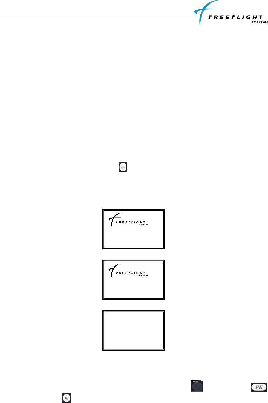
3.4.1 Entering Configuration Mode
To enter configuration mode on the TC-978:
• Hold down the function button while turning the mode knob from off to any
operating mode.
• In the configuration mode the front panel controller displays the following
messages on the screen
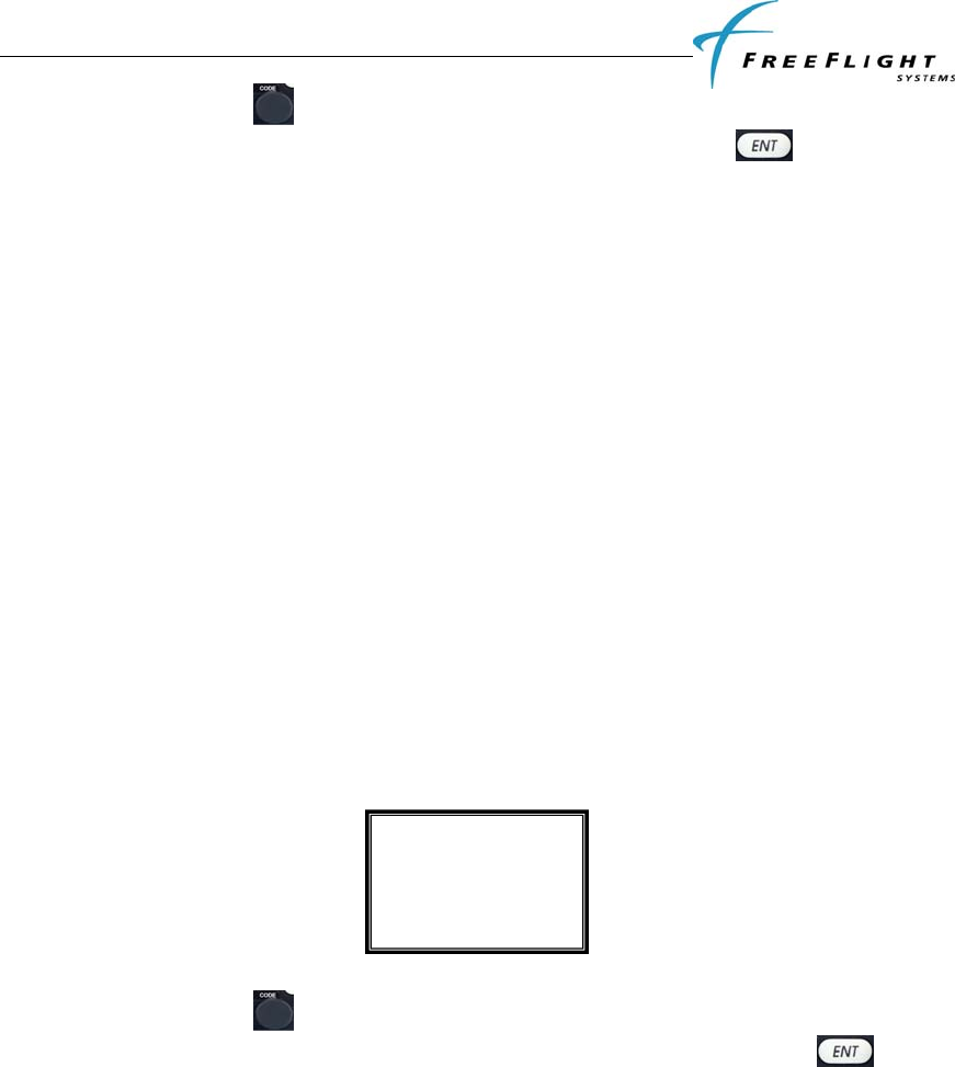
3.5 CONFIGURATION MODE SETUP
Configuration items can be changed using the Code Knob and the ENT
button. Pressing FN advances to the next configuration item.
Controller v1.7
HW v1.0 SW v1.6
FPGA v0.0
SETUP and TEST
mode. Press ENT
to proceed
FDL-978-TX ADS-B
Transmitter Installation Manual
86960, Revision A September 1, 2011
III-7
The following paragraphs detail the setup modes available for configuring the FDL-978-
TX.
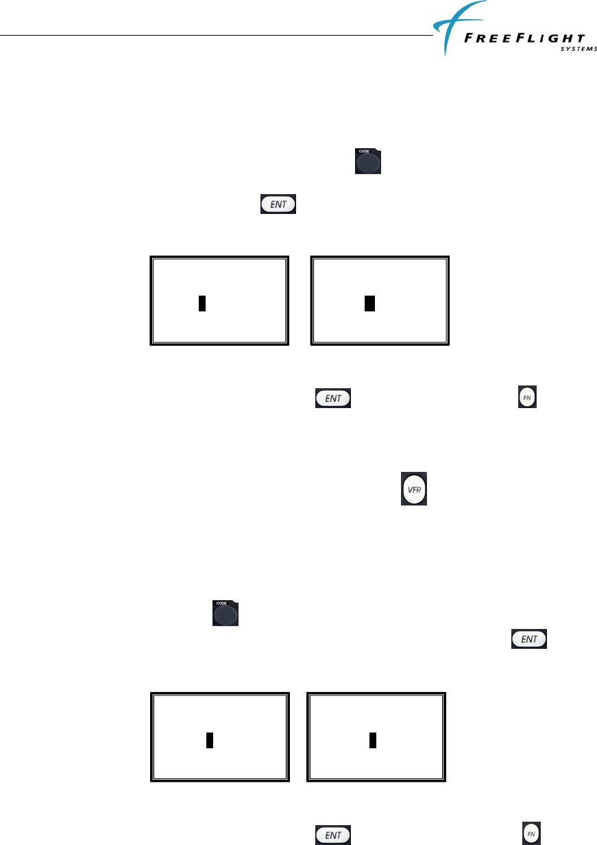
3.5.1 Aircraft Modes S (or ICAO) Address
The Mode S address is a 24 bit number assigned to the aircraft and is represented in a 6
character hexadecimal format. The rotary code knob is used to change each
character as required. Each character of the Mode S address is a number between 0 to
9 or a letter between A to F. When the key is pressed the cursor advances to the
next character as shown below.
To advance to the next configuration item without changing the ICAO address either
scroll through the 6 characters by pressing the key 6 times or press the key.
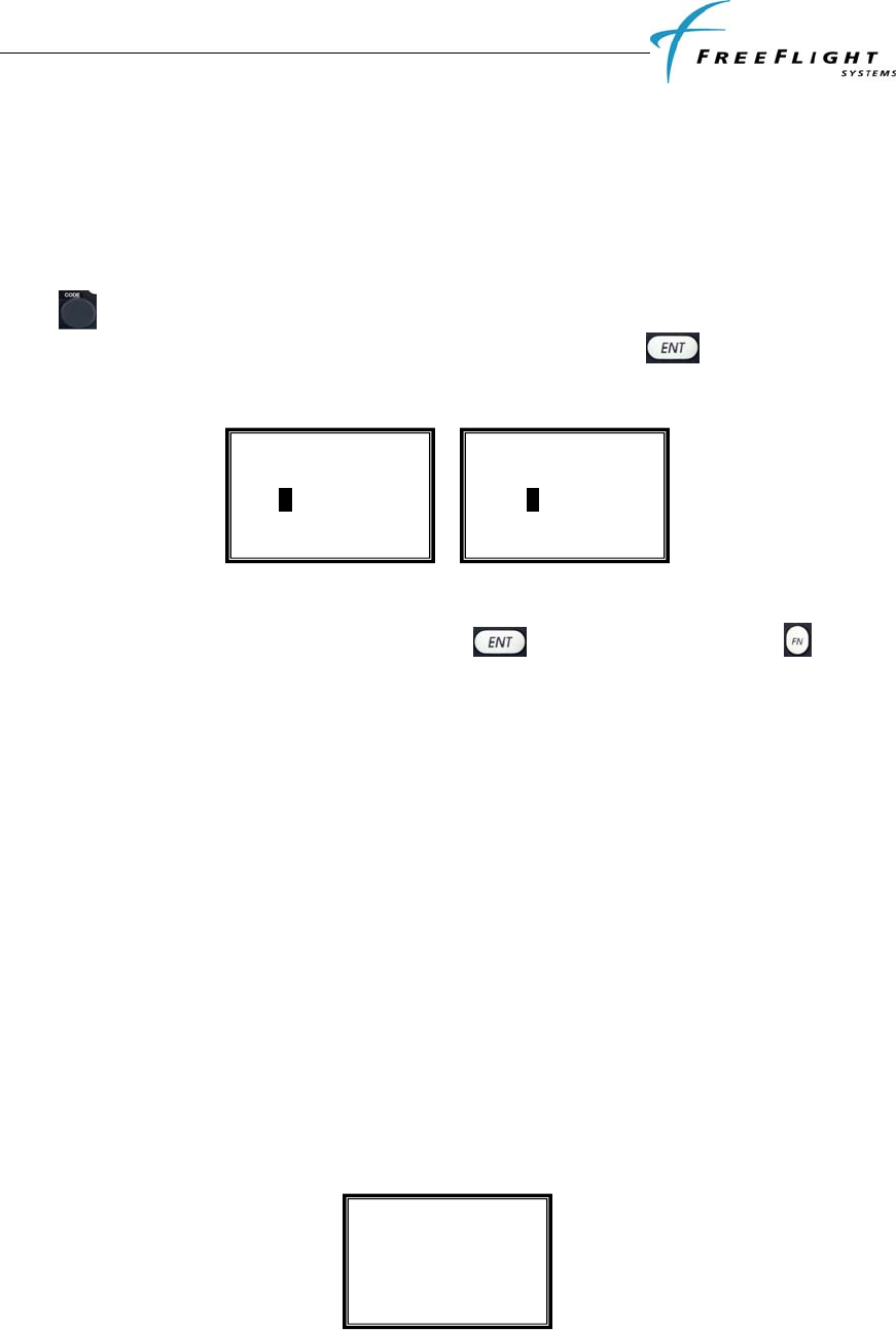
3.5.2 VFR Squawk Code
VFR squawk code is a pre-programmed default code when the pilot is flying VFR and
not in contact with ATC. When the pilot presses the VFR button the VFR squawk
code will replace the current squawk code. In the USA the VFR squawk code is 1200
and in most parts of Europe the VFR squawk code is 7000. Note: The default VFR
squawk code cannot be changed in flight and can only be set in the configuration mode.
The VFR Squawk code is a 12 bit number and is represented as a 4 character octal
number. The rotary code knob is used to change each character as required. Each
character of the squawk code is a number between 0 and 7. When the key is
pressed the cursor advances to the next character as shown below.
To advance to the next configuration item without changing the VFR squawk code either
scroll through the 4 characters by pressing the key 4 times or press the key.
3.5.3 Call Sign/VFR Flight ID
The Call Sign/ VFR flight ID is usually one of the following types:
Set Mode S Address
500000
Set VFR Squawk
1200
Set VFR Squawk
1000
Set Mode S Address
5A0000
FDL-978-TX ADS-B
Transmitter Installation Manual
86960, Revision A September 1, 2011
III-8
Type A – the characters corresponding to the registration marking of the aircraft
Type B – the telephony designator of the aircraft operating agency, followed by the last
four characters of the registration marking of the aircraft
Type C – the telephony designator of the aircraft operating agency, followed by the flight
identification
The Call Sign/ VFR Flight ID is an 8 character alpha-numeric string. The rotary code
knob is used to change each character as required. Each character of the flight ID is
a number between 0 to 9 and letter between A to Z. When the key is pressed the
cursor advances to the next character as shown below.
To advance to the next configuration item without changing the VFR Flight ID either
scroll through the 8 characters by pressing the key 8 times or press the key.
Note: The Call Sign/VFR Flight ID cannot be changed in flight and can only be set in the
configuration mode.
3.5.4 Maximum Airspeed
Airspeed can be used to help determine and verify the ON GROUND condition for
transmitting ON GROUND ADS-B message types. THE FDL-978-TX uses maximum
airspeed configuration to determine a maximum ON GROUND speed. There are 7
options to select maximum aircraft speed:
1. Unknown
2. Up to 75kt
3. 75 to 150kt
4. 150 to 300kt
5. 300 to 600kt
6. 600 to 1200kt
7. Over 1200kt
The display screen is as shown below with one of the options from above:
Select Maximum
Airspeed
75 to 150kt
Set VFR Flight ID
FFSVFRID
Set VFR Flight ID
FFSVFRID
FDL-978-TX ADS-B
Transmitter Installation Manual
86960, Revision A September 1, 2011
III-9
Rotate the code knob either clockwise or counterclockwise to display the options
above and select the maximum airspeed. Once selected, press the key to confirm
your selection and move to the next configuration item in the setup mode.
3.5.5 Aircraft (Emitter) Category
The following options are offered for selecting aircraft (emitter) category:
1. Unknown
2. Light Fixed Wing
3. Medium Fixed Wing
4. Large Fixed Wing
5. High Vortex B757
6. Heavy Fixed Wing
7. High G/ High Speed
8. Rotorcraft
9. Glider/Sailplane
10. Lighter than air
11. Parachutist
12. ULM/Hang/Paraglider
13. UAV
The display screen is as shown below with one of the options from above:
Rotate the code knob either clockwise or counterclockwise to display the options
above and select the correct aircraft category. Once selected, press the key to
confirm your selection and move to the next configuration item in the setup mode.
3.5.6 Squat Switch Type
The following options are offered for selecting aircraft squat switch type:
1. Not Connected
2. Low when ground
3. Low when airborne
The display screen is as shown below with one of the options from above:
Select Aircraft
Category
Light Fixed Wing
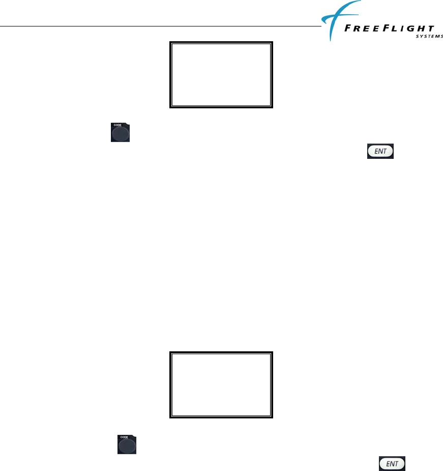
FDL-978-TX ADS-B
Transmitter Installation Manual
86960, Revision A September 1, 2011
III-10
Rotate the code knob either clockwise or counterclockwise to display the options
above and select the correct squat switch type. Once selected, press the key to
confirm your selection and move to the next configuration item in the setup mode.
3.5.7 Serial IN Channel X Data Type
(X = channel number) The FDL-978-TX can receive data via three serial ports. The
following options are offered for selecting serial input type for each individual input serial
channel of the FDL-978-TX:
1. Not Used
2. GPS-FreeFlight
3. Air Data Computer
4. Altitude Encoder
The display screen is as shown below with one of the options from above:
Rotate the code knob either clockwise or counterclockwise to display the options
above and select the correct serial input type. Once selected, press the key to
confirm your selection and move to the next configuration item in the setup mode.
Note: If “Not Used” is selected then the serial input line speed configuration mode will
not be displayed and the next configuration mode item will be displayed.
3.5.8 Serial IN Channel X Line Speed
(X = channel number) The following options are offered for selecting the serial input
baud rate for each channel data type:
1. 4800
2. 9600
3. 19200
4. 38400
5. 57600
6. 115200
7. 230400
Serial IN chan 2 Data
Type
GPS - FreeFlight
Select Squat Switch
Type
Low when airborne
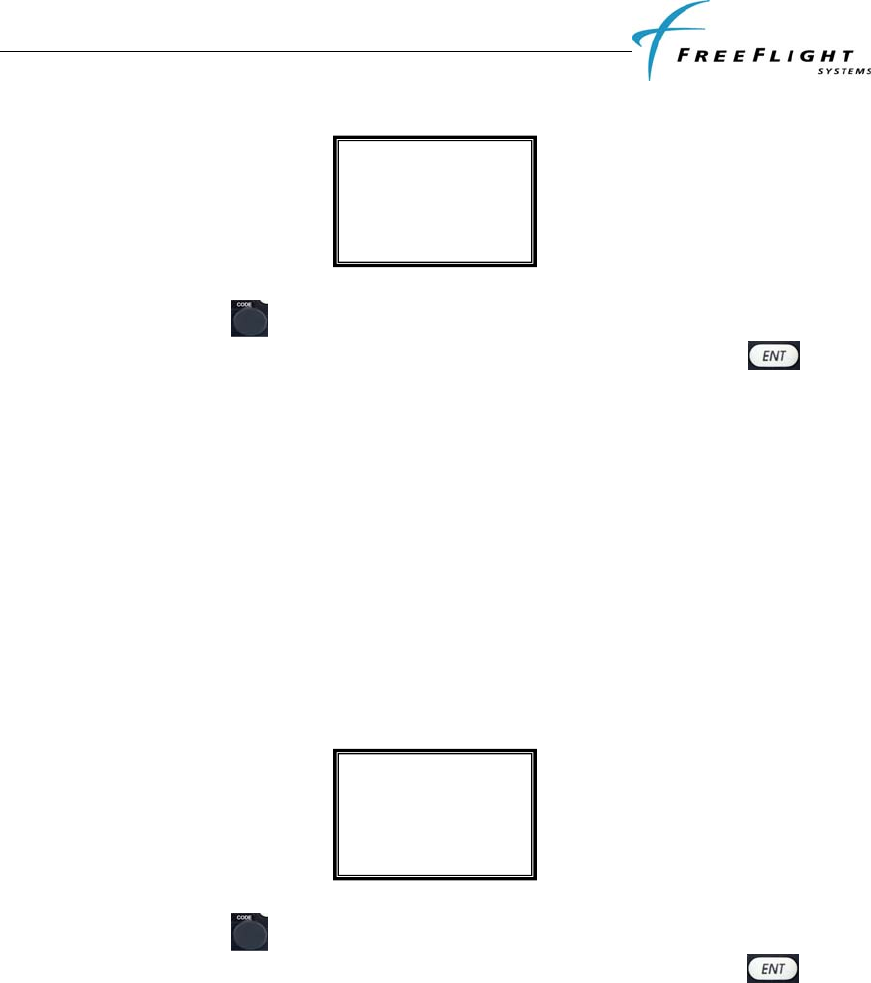
FDL-978-TX ADS-B
Transmitter Installation Manual
86960, Revision A September 1, 2011
III-11
The display screen is as shown below with one of the options from above:
Rotate the code knob either clockwise or counterclockwise to display the options
above and select the correct serial input speed. Once selected, press the key to
confirm your selection and move to the next configuration item in the setup mode.
3.5.9 Serial OUT Channel X Data Type
(X = channel number) The FDL-978-TX can transmit data via two serial ports. The
following options are offered for selecting serial output type for each individual channel
of the FDL-978-TX:
1. Not Used
2. Altitude Encoder
3. TIS/FIS
4. ADS-B Pass Thru
The display screen is as shown below with one of the options from above:
Rotate the code knob either clockwise or counterclockwise to display the options
above and select the correct serial output type. Once selected, press the key to
confirm your selection and move to the next configuration item in the setup mode.
Note: If “Not Used” is selected then the serial output line speed configuration mode will
not be displayed and the next configuration mode item will be displayed.
3.5.10 Serial OUT Channel X Line Speed
(X = channel number) The following options are offered for selecting the serial output
baud rate for each channel data type:
1. 4800
2. 9600
3. 19200
4. 38400
5. 57600
Serial OUT chan 6
Data Type
TCAD Traffic
Serial IN chan 2 Line
Speed
19200
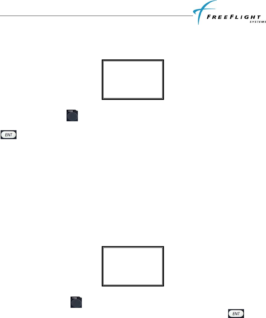
FDL-978-TX ADS-B
Transmitter Installation Manual
86960, Revision A September 1, 2011
III-12
6. 115200
7. 230400
The display screen is as shown below with one of the options from above:
Rotate the code knob either clockwise or counterclockwise to display the options
mentioned above and select the correct serial output speed. Once selected, press the
key to confirm your selection and move to the next configuration item in the setup
mode.
3.5.11 ARINC IN Channel X Data Type
(X = channel number) The FDL-978-TX can receive data via two ARINC 429 input ports.
The following options are offered for selecting ARINC 429 input type for each individual
channel of the FDL-978-TX:
1. Not Used
2. GPS
3. Air Data Computer
The display screen is as shown below with one of the options from above:
Rotate the code knob either clockwise or counterclockwise to display the options
above and select the correct ARINC input type. Once selected, press the key to
confirm your selection and move to the next configuration item in the setup mode.
Note: If “Not Used” is selected then the ARINC input line speed configuration mode will
not be displayed and the next configuration mode item will be displayed.
3.5.12 ARINC IN Channel X Interface Speed
(X = channel number) The following options are offered for selecting the ARINC interface
speed for each channel data type:
1. Low
2. High
ARINC IN chan 2
Data Type
GPS
Serial OUT chan 1
Line Speed
19200
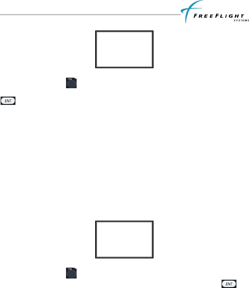
FDL-978-TX ADS-B
Transmitter Installation Manual
86960, Revision A September 1, 2011
III-13
The display screen is as shown below with one of the options from above:
Rotate the code knob either clockwise or counterclockwise to display the options
above and select the correct ARINC input interface speed. Once selected, press the
key to confirm your selection and move to the next configuration item in the setup
mode.
3.5.13 GPS Certification
The FDL-978--TX needs a valid GPS source so that aircraft position can be transmitted
in its ADS-B message. The GPS source is usually certified to a RTCA-DO178B software
level as mandated by the governing FAA TSO. The following GPS software certification
levels can be selected:
1. Uncertified
2. Level D
3. Level C
4. Level B
The display screen is as shown below with one of the options from above:
Rotate the code knob either clockwise or counterclockwise to display the options
above and select the correct GPS certification level. Once selected, press the key
to confirm your selection and move to the next configuration item in the setup mode.
3.5.14 GPS NAC Velocity
The GPS source used in the installation should have a navigation accuracy category for
velocity (NACv) setting specified by the GPS manufacturer. Use the GPS manufacturer’s
setting to set this. The following options are available for selection.
1. Unknown
2. 10 meters/ sec
3. 3 meters/ sec
4. GPS Auto
The display screen is as shown below with one of the options from above:
Select GPS
Certification
Level C
ARINC IN chan 1
Interface Speed
High
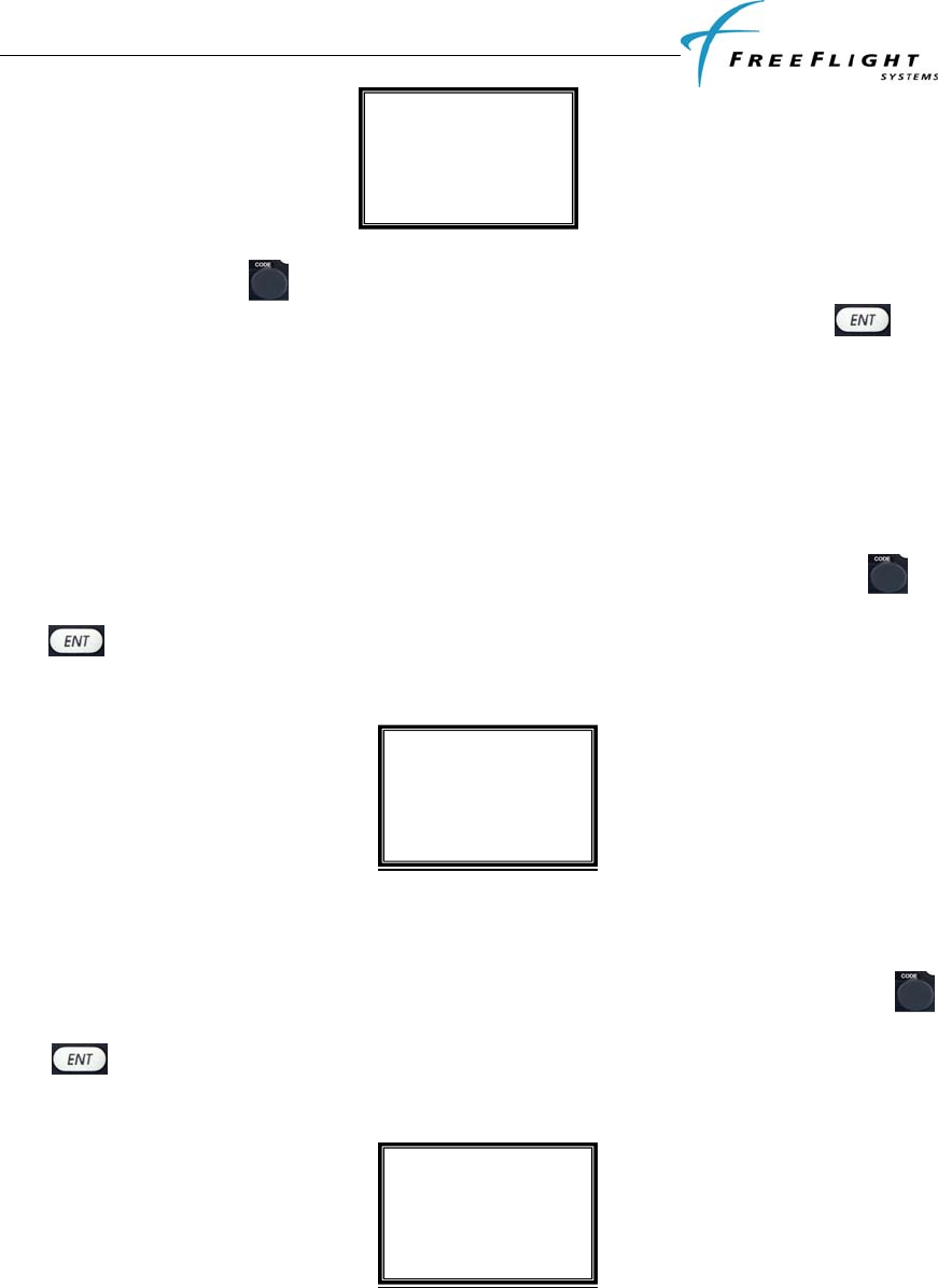
FDL-978-TX ADS-B
Transmitter Installation Manual
86960, Revision A September 1, 2011
III-14
Rotate the code knob either clockwise or counterclockwise to display the options
above and select the correct GPS certification level. Once selected, press the key
to confirm your selection and move to the next configuration item in the setup mode.
Settings 1, 2 and 3 are hard-coded settings in the software. Setting 4 is automatically set
from the velocity FOM (VFOM) data from the GPS unit. The NACv value is hard-coded
to be no better than 3 meters/sec even if GPS Auto is selected.
3.5.15 Aircraft Length
The aircraft length can be set from 1 meter to 75 meters by rotating the code knob
either clockwise or counterclockwise to display the correct length. Once selected, press
the key to confirm selection and move to the next configuration item in the setup
mode.
3.5.16 Aircraft Width
The aircraft width can be set from 1 meter to 80 meters by rotating the code knob
either clockwise or counterclockwise to display the correct width. Once selected, press
the key to confirm selection and move to the next configuration item in the setup
mode.
3.5.17 GPS Reference Position Offset
There are three modes by which the GPS reference offset can be set:
1. Unknown
Select GPS
NAC velocity
Unknown
Set Aircraft
Width
Meters: 40
Set Aircraft
Length
Meters: 50
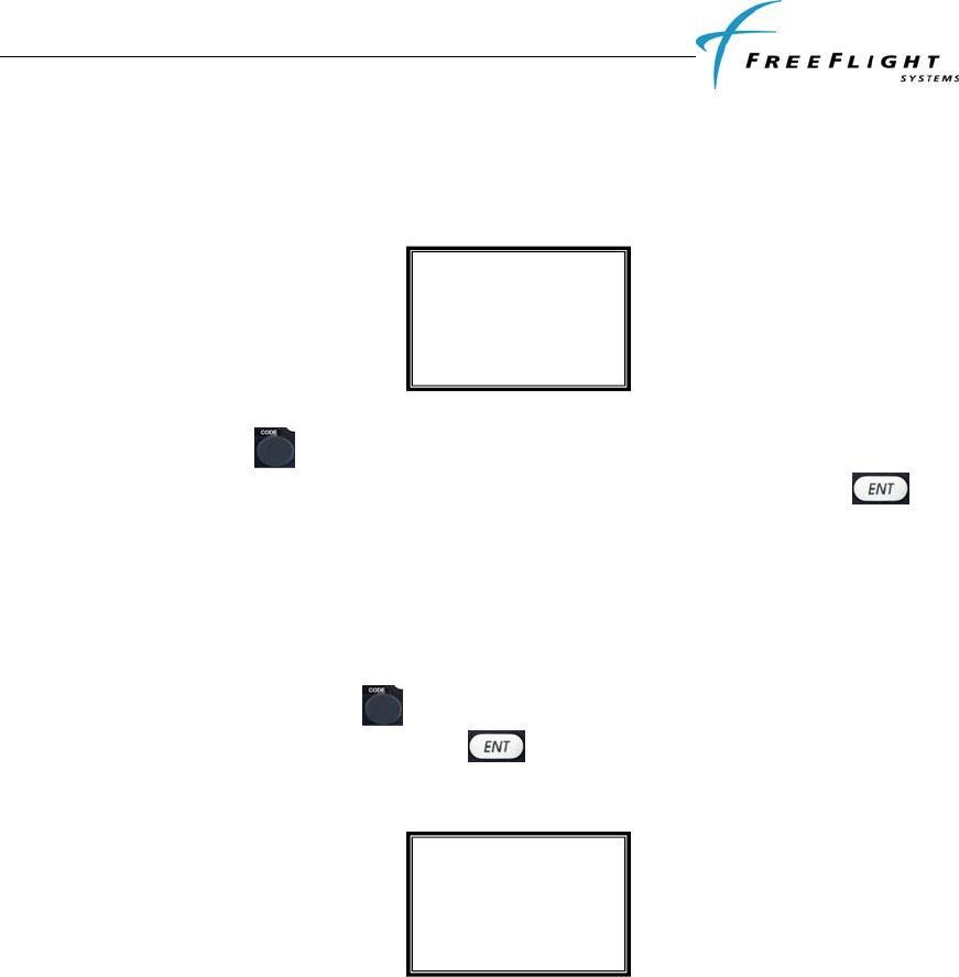
FDL-978-TX ADS-B
Transmitter Installation Manual
86960, Revision A September 1, 2011
III-15
2. Auto set by GPS
3. Manual set here
The display screen is as shown below with one of the options from above:
Rotate the code knob either clockwise or counterclockwise to display the options
above and select the correct GPS reference offset. Once selected, press the key
to confirm your selection. If “Unknown” or “Auto Set by GPS” is selected the next
configuration item in the setup mode will be displayed. If “Manual Set here” is selected
then options for manually entering the GPS antenna reference offset are displayed as
below:
The antenna distance from the nose can be entered anywhere between 2 meters to 60
meters by rotating the code knob either clockwise or counterclockwise to display the
correct distance. Once selected, press the key to confirm selection and move to
the lateral offset configuration item in the setup mode.
The antenna lateral offset has the following options that can be selected:
1. Unknown
2. Left 0-2 meters
3. Left 2-4 meters
4. Left 4+ meters
5. Central
6. Right 0-2 meters
7. Right 2-4 meters
8. Right 4+ meters
The display screen ia as shown below with one of the options from above:
Antenna Distance
From Nose
Meters: 25
GPS Reference
Position Offset
Auto Set by GPS
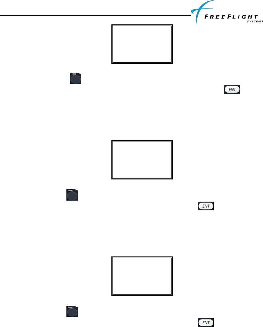
FDL-978-TX ADS-B
Transmitter Installation Manual
86960, Revision A September 1, 2011
III-16
Rotate the code knob either clockwise or counterclockwise to display the options
above and select the correct antenna offset. Once selected, press the key to
confirm selection and move to the next configuration item in the setup mode.
3.5.18 1090 MHz Receiver Installed
The display screen is as shown below with either Yes or No options.
Rotate the code knob either clockwise or counterclockwise to display either “Yes” or
“No” and select the correct option. Once selected, press the key to confirm
selection and move to the next configuration item in the setup mode.
3.5.19 UAT Receiver Installed
The display screen is as shown below with either Yes or No options.
Rotate the code knob either clockwise or counterclockwise to display either “Yes” or
“No” and select the correct option. Once selected, press the key to confirm
selection and move to the next configuration item in the setup mode.
3.5.20 UAT Antenna Diversity
The FDL-978-TX provides the flexibility for installing either one or two approved UAT
antennas. A single antenna can either be installed on the top of the aircraft fuselage or
on the belly of the aircraft. When two antennas are installed they are installed on the top
and bottom of the aircraft. The following options can be selected:
1. Top Only
2. Bottom Only
UAT Receiver
Installed
No
1090MHz Receiver
Installed
No
Antenna
Lateral Offset
Left 4+ meters
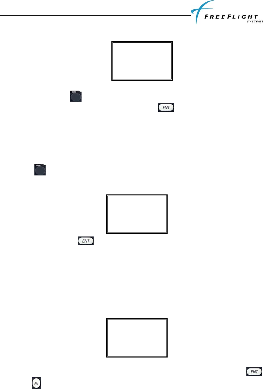
FDL-978-TX ADS-B
Transmitter Installation Manual
86960, Revision A September 1, 2011
III-17
3. Dual
Rotate the code knob either clockwise or counterclockwise to display the correct
antenna diversity option. Once selected, press the key to confirm selection and
move to the next configuration item in the setup mode.
Note: It is recommended to install dual antennas for maximum coverage.
3.5.21 Check Ground on UAT Antenna
Confirm if the UAT antenna(s) used have a ground connection that allows the FDL-978-
TX to check if the antenna is installed by selecting the YES or No options. Rotate the
code knob either clockwise or counterclockwise to display either “Yes” or “No” and
select the correct option. The display is as shown below:
Once selected, press the key to confirm selection and complete the configuration
setup.
3.6 TEST AND CALIBRATION
3.6.1 Local Voltage Supply Test
The front panel controller of the FDL-978-TX utilizes a D.C supply voltage of 5.5V to 8V.
The display typically shows the supply voltage between 6.5V to 7.1V as shown below.
There is no option or configuration to be entered or selected in this step. Press the
key or the key and move to the next configuration item in the setup mode.
Local Supply
Voltage Test
6.9 V
Check Ground
on UAT Antenna
Yes
UAT Antenna
Diversity
Top Only

FDL-978-TX ADS-B
Transmitter Installation Manual
86960, Revision A September 1, 2011
III-18
3.6.2 Calibrate Altitude Encoder
The TC-978 includes a built-in altitude encoder. The front panel reports pressure altitude
on pin 4 of the DB-9 male connector on the back of the TC-978 as RS-232 serial data, at
9600 bps, using the format commonly called “Icarus” format. The installation manual
provides further details of interfacing the altitude encoder with the primary static
pressure of the aircraft altimeter. The calibrate altitude encoder setup allows the
recalibration of the altitude encoder. This ensures that the altitude seen on the pilot’s
primary altimeter is the same as what is transmitted out of the FDL-978-TX. The
maximum allowed difference between the primary altimeter and the altitude encoder is
125 feet in ETSO C88a and TSO C88b. The altitude encoder in the Front Panel
Controller is accurately calibrated in the factory to be within 50 feet of the applied
pressure altitude at all altitudes, whereas the allowed error in the primary altimeter
increases with altitude, and above 18,000 feet the altimeter error alone may exceed 125
feet. It is therefore possible that the combination of the allowed errors in the encoder and
the primary altimeter may exceed 125 feet, in which case the altitude encoder must be
adjusted to correspond to the primary altimeter.
Note: The purpose of calibrating the encoder is to make the output correspond to the
primary altimeter. The encoder calibration procedure must therefore only be undertaken
after the primary altimeter has been tested and found to comply with the relevant
standards.
3.6.2.1 Calibration Equipment
To calibrate the encoder the TC-978 must be powered up and you will need a pitot-static
test set with the appropriate adapters to connect to the static port on the aircraft. The
pitot-static test set should be able to drive the altitude down to sea level, and above the
service ceiling of the aircraft.
No test set is required – the calibration procedure displays all the information you need
on the screen of the Front Panel Controller
3.6.2.2 Calibration Procedure
There are two adjustment points on the altitude encoder, a low altitude adjustment point,
and a high altitude adjustment point. The low altitude point adjusts the correspondence
at sea level, and the high altitude point adjusts the correspondence at the altitude limit of
the encoder. Since the altitude limit of the encoder is likely to be higher than the service
ceiling of the aircraft, it is sufficient to set the upper adjustment at the service ceiling of
the aircraft.
Note: DO NOT EXCEED THE ALTITUDE OR RATE OF CLIMB LIMITS OF THE PITOT-
STATIC INSTRUMENTS OF THE AIRCRAFT. The TC-978 altitude encoder is a solid
state device and will not be affected by excess altitude or rate of climb and descent, but
the mechanical instruments in the aircraft can easily be damaged by being driven
beyond their intended range.
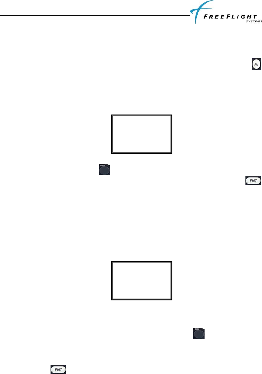
FDL-978-TX ADS-B
Transmitter Installation Manual
86960, Revision A September 1, 2011
III-19
1. Set the primary altimeter subscale setting to 1013.2 hPa, 29.92 in hg.
2. Connect the pitot-static test set to the aircraft.
3. You can enter the altitude encoder calibration setup either after following the
steps from above in order or you can enter directly by holding the FN
button down on the controller on power up to enter setup mode. And skipping
over the configuration modes until reaching the calibrate altitude encoder
section. When you are in the calibrate altitude encoder setup mode the display
shows the following information;
4. Rotate the code knob either clockwise or anticlockwise to display either
“Yes” or “No” and select the correct option. Once selected, press the
key to confirm your selection and move to the next configuration item in the
setup mode. If “No” is selected then the next configuration item in the setup
mode will be displayed. If “Yes” is selected then options for calibrating the
altitude encoder is as shown below.
5. On selecting “Yes” the low altitude set point will now be active, and an altitude
will be displayed as below.
6. On the static test set, drive the altitude to 0 feet.
7. Read the primary altimeter value; rotate the code knob either clockwise or
anticlockwise until the altitude displayed on the front panel matches the
aircraft primary altimeter.
8. Press and the display will move to the mid altitude set point and an
altitude will be displayed as shown below. On the static test set, drive the
altitude to the middle range ceiling of the aircraft.
Alt Encoder Cal
Low Altitude 0ft
100
Calibrate Alt
Encoder
Yes
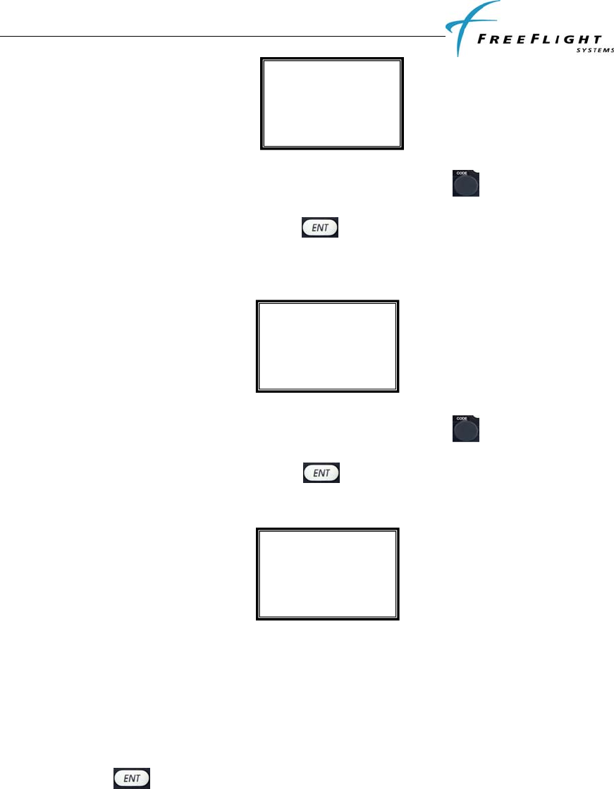
FDL-978-TX ADS-B
Transmitter Installation Manual
86960, Revision A September 1, 2011
III-20
9. Read the primary altimeter value; rotate the code knob either clockwise or
anticlockwise until the altitude displayed on the front panel matches the
aircraft primary altimeter. Press and the display will move to the high
altitude set point and an altitude will be displayed as shown below. On the
static test set, drive the altitude to the service ceiling of the aircraft.
10. Read the primary altimeter value; rotate the code knob either clockwise or
anticlockwise until the altitude displayed on the front panel matches the
aircraft primary altimeter. Press and the display will move to the test
altitude screen which is the next configuration item in the setup mode.
11. To complete the testing you should leave the front controller screen displaying
the encoder altitude, and exercise the altitude on the static test set across the
altitude range of the aircraft. The display will be as shown above for pressure
reported. Use at least 10 test points, and verify that in each case the altitude
displayed on the primary altimeter and the altitude displayed on the front panel
correspond within the 125 foot tolerance. Lightly tap the altimeter at each test
point to eliminate friction effects. When the correspondence test is complete,
press again on the front panel, and power off the system.
3.6.3 Pressure Altitude Reported
Pressure altitude is displayed after the altitude calibration setup has been completed.
The display shows the reported pressure altitude and should match the altitude reported
by the primary altimeter.
Pressure Altitude
Reported
608
Alt Encoder Cal
High Altitude FL300
608
Alt Encoder Cal
Mid Altitude FL100
308

FDL-978-TX ADS-B
Transmitter Installation Manual
86960, Revision A September 1, 2011
III-21
Press and the display will instruct completion of setup and power off the system.
Pressure Altitude
Reported
308

FDL-978-TX ADS-B
Transmitter Installation Manual
86960, Revision A September 1, 2011
IV-1
SECTION IV TROUBLESHOOTING
4.1 GENERAL
This section provides information for troubleshooting problems that occur after FDL-978-TX installation.
This section contains information on how to use the FDL-978-TX LEDs and TC-978 Controller display to
troubleshoot installation problems. Refer to SECTION III to setup and configure the system.
4.2 FDL-978-TX LED TROUBLSHOOTING PROCEDURE
The following is a quick reference troubleshooting guide using the FDL-978-TX LEDs:
PROBLEM POTENTIAL CAUSE TROUBLESHOOTING
No LED Activity No power Verify power is turned on
Check power connections to unit.
Tx LED not active Unit is not transmitting ADS-
B messages
Check antenna connections
Check TC-978 Warning messages
Rx LED not active Normal operation for
transmitter
Status LED is on A fault with the unit or the
attached GPS exists
Check TC-978 Warning messages
Check GPS connection/configuration
GPS LED is flashing
slowly
GPS is acquiring satellites Allow 2-3 minutes for GPS tracking
Check GPS antenna
Check GPS for problems
GPS LED is off GPS not communicating or
has a fault
Check GPS connection/configuration
Check GPS for fault

FDL-978-TX ADS-B
Transmitter Installation Manual
86960, Revision A September 1, 2011
IV-2
4.2.1 UAT Status LED/Discrete Fault Indications
The status LED/discrete is an indicator of a warning or fault reported by the FDL-978-TX. The status LED
is visible on the FDL-978-TX or the discrete may be connected to a cockpit annuciator. Potential faults that
cause the UAT Status LED to turn on and the Status Discrete to be active (ground) are listed below:
PROBLEM REPORTED REPORTED BY
RF Transmission Failure PBIT
Bottom Antenna Not Connected (If DC ground check configured) PBIT
Top Antenna Not Connected (If DC ground check configured) PBIT
RF Transmission Power Too Low PBIT
GWSS not communicating or reporting fault PBIT
RF Transmit Power Supply Low PBIT
Internal Temperature Too High PBIT
RF Transmit Reverse Power too High PBIT
Nominal Message Rate not once per second PBIT
Broadcast monitor failure – All message types not transmitted PBIT
Nominal Message Rate not once per second PBIT
Internal Power Supply Failure PBIT
UART Serial Port Loopback Test Failure POST
ARINC 429 Channel Loopback Test Failure POST
General Processing/Interface Hardware Failure POST
Transmitter Hardware Check Failure POST

FDL-978-TX ADS-B
Transmitter Installation Manual
86960, Revision A September 1, 2011
IV-3
4.3 WARNING MESSAGES
If the FDL-978-TX detects a problem the TC-978 display will indicate WARNING with a brief statement
of the problem. Depending on the nature of the problem the FDL-978-TX may not be transmitting ADS-B
messages.
Press ENT to return the Control Head to normal operation. The LCD will display an icon in the upper left-
hand corner to indicate that warnings are still present. To enter the Warning View mode, press FN four
times. In this mode, the control head continually requests the active warning messages from the FDL-978-
TX and displays them on the Control Head. Press FN again to exit this mode and return to normal
operation.
TC-978 WARNING MESSAGES
WARNING MSG DESCRIPTION
Synth Unlock Transmitter carrier frequency lock fault
Tx Fault UAT transmitter fault
Tx Power Low UAT transmitter power low during transmit
Tx PSU High UAT transmitter power supply output too high
Tx PSU Low UAT transmitter power supply output too low
Squitter Fail Transmitter message modulation fault
Remote Hot FDL-978-TX internal temperature too high
No ADS-B Pos GPS position not acquired, satellite tracking lost, or GPS not
communicating
GPS Fault GPS indicates a fault or not responding or no time mark pulse
detected
Top ant Fault Top antenna disconnected
Bot ant Fault Bottom antenna disconnected
PSU Fail Internal DC power supply failure
ADC Fault ADC or Altitude sensor fault or not responding
4.3.1 TC-978 Warning Message Troubleshooting
The following is a quick reference troubleshooting guide using the TC-978 Warnings:
WARNING POTENTIAL CAUSE TROUBLESHOOTING
Synth Unlock
Transmitter can’t lock to
carrier frequency Cycle Power on the FDL-978-TX
Return for maintenance if problem
persists
TX Fault Generic Transmitter Fault –
POST, transmit, address,
broadcast, or nominal rate
failure.
Cycle Power on the FDL-978-TX
Check for valid ICAO address config
Tx Power Low Transmitter power too low Check antennas and cabling
Return for maintenance if problem persists
Tx PSU High Transmitter power supply voltage
too high.
Cycle Power on the FDL-978-TX. Return for
maintenance if problem persists.
Tx PSU Low Transmitter power supply voltage
too low.
Cycle Power on the FDL-978-TX. Return for
maintenance if problem persists.
Squitter Fail Transmitter modulation fault Cycle Power on the FDL-978-TX. Return for
maintenance if problem persists.
Remote Hot FDL-978-TX internal temperature
too high.
Cycle Power on the FDL-978-TX.
Turn power off for several minutes then back

FDL-978-TX ADS-B
Transmitter Installation Manual
86960, Revision A September 1, 2011
IV-4
WARNING POTENTIAL CAUSE TROUBLESHOOTING
on.
Return for maintenance if problem persists.
No ADS-B Pos GPS position not acquired,
satellite tracking lost, or
GPS not communicating
Verify GPS is functioning.
Verify GPS Port Configuration and
speed.
Verify GPS Cable connection.
GPS Fault Verify GPS is functioning.
Verify Incoming GPS Port
Configuration and speed.
Verify GPS Cable connection.
Top ant Fault Top antenna disconnected. Check antenna connection.
Ensure antenna is DC grounded.
Disable DC Grnd Check in config if
antennas are not DC grounded.
Bot ant Fault Bottom antenna
disconnected. Check antenna connection.
Ensure antenna is DC grounded.
Disable DC Grnd Check in config if
antennas are not DC grounded.
PSU Fail Internal DC Power Supply failure. Cycle Power on the FDL-978-TX. Return for
maintenance if problem persists.
ADC Fault Air Data Computer or
Altitude encoder fault or not
responding.
Verify ADC is functioning.
Verify ADC Port Configuration and
speed.
Verify ADC Cable connection.

FDL-978-TX ADS-B
Transmitter Installation Manual
86960, Revision A September 1, 2011
V
-1
SECTION V RTCA/DO-160 ENVIRONMENTAL
QUALIFICATION FORMS
5.1 FDL-978-TX UAT DO-160 QUALIFICATION
CONDITIONS PARA CATEGORY (DO-160G)
Temperature and Altitude 4 C4(-40ºC to +70ºC)/D/A
Operating Low Temperature
Operating High Temperature
Short-Time Operating Low Temperature
Short-Time Operating High Temperature
Ground Survival Low Temperature
Ground Survival High Temperature
Loss of Cooling
Altitude
Decompression
Overpressure
4.5.2
4.5.4
4.5.1
4.5.3
4.5.1
4.5.3
4.5.5
4.6
4.6.2
4.6.3
-40°C (C4)
+70°C (C4)
-40°C (C4)
+70°C (C4)
-55°C (C4)
+85°C (C4)
n/a
+50,000ft (D)
+50,000ft (A)
-15,000ft (A)
Temperature Variation 5 B
Humidity 6 A
Shock/Crash Safety 7 B
Vibration 8 S (Zone 1, curve C) & U2
Explosive Atmosphere 9 n/a
Waterproofness 10 n/a
Fluids Susceptibility 11 n/a
Sand and Dust 12 n/a
Fungus Resistance 13 n/a
Salt Fog 14 n/a
Magnetic Effect 15 Z
Power Input 16 B
Voltage Spike 17 A
Audio Frequency Conducted Susceptibility –
Power Inputs
18 B
Induced Signal Susceptibility 19 AC
Radio Frequency Susceptibility 20 TT
Emission of Radio Frequency Energy 21 MM
Lightning, Induced Transient Susceptibility 22 A2J3L3
Lightning Direct Effects 23 n/a
Icing 24 n/a
Electrostatic Discharge 25 A
Fire, Flammability 26 C

FDL-978-TX ADS-B
Transmitter Installation Manual
86960, Revision A September 1, 2011
V
-2
5.2 TC-978 CONTROLLER DO-160 QUALIFICATION
CONDITIONS PARA CATEGORY (DO-160E)
Temperature and Altitude 4 C4 (-20ºC to +55ºC)
Temperature Variation 5 A
Humidity 6 A
Shock/Crash Safety 7 B
Vibration 8 U (Curve G)
Explosive Atmosphere 9 n/a
Waterproofness 10 W (front face only)
Fluids Susceptibility 11 n/a
Sand and Dust 12 n/a
Fungus Resistance 13 n/a
Salt Fog 14 n/a
Magnetic Effect 15 Z
Power Input 16 n/a
Voltage Spike 17 n/a
Audio Frequency Conducted Susceptibility –
Power Inputs
18 n/a
Induced Signal Susceptibility 19 AC
Radio Frequency Susceptibility 20 TT
Emission of Radio Frequency Energy 21 M
Lightning, Induced Transient Susceptibility 22 n/a
Lightning Direct Effects 23 n/a
Icing 24 n/a
Electrostatic Discharge 25 n/a
Fire, Flammability 26 n/a

FDL-978-TX ADS-B
Transmitter Installation Manual
86960, Revision A September 1, 2011
V
I-1
SECTION VI SERIAL INTERFACE SPECIFICATIONS
Two data formats may be selected to accept input from external Altitude sensors:
• Encoder Altitude – gray-code to serial altitude converters, etc.
• Air Data Computer – To select a data format, refer to section B.4. The baud rate of each of these
formats is automatically set; ENCODER is 9600 baud and RMI is 1200 baud.
6.1 ALTITUDE ENCODER FORMAT
The Altitude Encoder data format accepts messages with the following parameters:
Baud: 9600
Parity: None
Start Bit: 1
Data Bits: 8
Stop Bit: 1
Update Rate: 1 msg/sec
Compatible devices include Rosetta Encoders and Serializers (ARS 50 and ARS 100). The compatible
format for altitude information is the following 10 byte ASCII message:
BYTE 0 1 2 3 4 5 6 7 8 9
CONTENTS A L T 1 2 3 4 5 c/r
Some examples include: 'ALT 00000' 0 feet
'ALT -1200' -1200 feet
'ALT 62505' 62,505 feet
'ALT 05604' 5,604 feet
6.2 AIR DATA COMPUTER FORMAT
The Air Data computer format accepts messages withthe following parameters:
Baud: 9600
Parity: None
Start Bit: 1
Data Bits: 8
Stop Bit: 1
Update Rate: 1 msg/sec
Air Data messages are accepted when the serial port is set to "ENCODER". A packet consists of a set of
ASCII message strings. The first character of each packet is an ASCII Start-of-Text (STX = 02H). The last
character of each packet will be an ASCII End-of-Text (ETX = 03H). Each message string begins with one
ASCII character to identify it as an Air Data message ("Z"). The second character identifies which message
it is. The rest of the string consists of one or more alphanumeric ASCII fields. Each message field ends
with a carriage return, line feed (CR = 0D0AH). All numeric fields are ASCII decimal, right justified and
zero filled. If the Air Data Computer cannot supply data in a particular field, the field is filled with dashes
("-" = 2DH). The table below lists the message items used by the FDL-978-TX. Additional items may be in
the message but they are not used by the FDL-978-TX.
ITEM FORMAT CONTENTS DESCRIPTION
ZBddd True Air Speed ddd = knots (40 to 600)
ZDsdddd Pressure Altitude s = sign, dddd = tens of feet
(-100 to +5999)

FDL-978-TX ADS-B
Transmitter Installation Manual
86960, Revision A September 1, 2011
V
I-2
ITEM FORMAT CONTENTS DESCRIPTION
ZKsddd Vertical Speed s = sign, ddd = tens of feet/minute (-600 to
+600)
ZRddd Packet Checksum ddd = number (0 to 255)

FDL-978-TX ADS-B
Transmitter Installation Manual
86960, Revision A September 1, 2011
V
II-1
SECTION VII ADS-B COMPLIANCE
ADS-B PARAMETERS SUPPORTED
# Input Data Element Comment
(Use within the FDL-978-TX)
1 ICAO 24-bit Address Installation configuration
2 Address Selection (ICAO vs Temporary) Anonymous discrete input
3 Latitude From GPS data
4 Longitude From GPS data
5 Altitude Type Selection (Barometric vs Geometric) Baro unless invalid or inhibited
6 Barometric Pressure Altitude From altitude/air data sensor
7 Geometric Altitude From GPS data
8 NIC From GPS data
9 Automatic AIRBORNE/ON-GROUND Indication Air/Ground discrete input
10 North Velocity From GPS data
11 East Velocity From GPS data
12 Ground Speed From GPS data
13 Track Angle From GPS data
14 Heading From GPS data
15 Barometric Vertical Rate From altitude/air data sensor
16 Geometric Vertical Rate From GPS data
17 A/V Length and Width, and POA Installation configuration
18 UTC 1 PPS Timing From GPS Data
19 Emitter Category Installation configuration
20 Call Sign From controller interface (TC-978)
21 Emergency/Priority Status Selection From controller interface (TC-978)
22 SIL GPS with HIL or HPL only
23 System Design Assurance (SDA) Installation configuration
24 SIL Supplement GPS with HIL or HPL only
25 NACP From GPS data
26 NACV From GPS data
27 NICBARO Non-Gilham altitude sensors only
28 Capability Codes Installation configuration
29 TCAS Installed and Operational Installation configuration
30 TCAS/ACAS resolution advisory flag TCAS RA discrete input
31 IDENT Switch Active From controller interface (TC-978)
32 Call Sign Identification From controller interface (TC-978)
33 Geometric Vertical Accuracy (GVA) Installation configuration
34 Single Antenna Flag Installation configuration
35 NIC Supplement Flag From GPS data
36 Selected Altitude Type Not supported in current software
37 Selected Altitude Setting Not supported in current software
38 Barometric Pressure Setting Not supported in current software
39 Selected Heading Not supported in current software
40 Status of MCP/FCU Mode Not supported in current software
41 Mode Indicators: Autopilot Engaged Not supported in current software
42 Mode Indicators: VNAV Engaged Not supported in current software
43 Mode Indicators: Altitude Hold Mode Not supported in current software
44 Mode Indicators: Approach Mode Not supported in current software
45 Mode Indicators: LNAV Engaged Not supported in current software
46 Radio Height Not supported in current software
47 Pressure Altitude Disable From controller interface (TC-978)
48 Airspeed From altitude/air data sensor
49 Flight Plan ID From controller interface (TC-978)
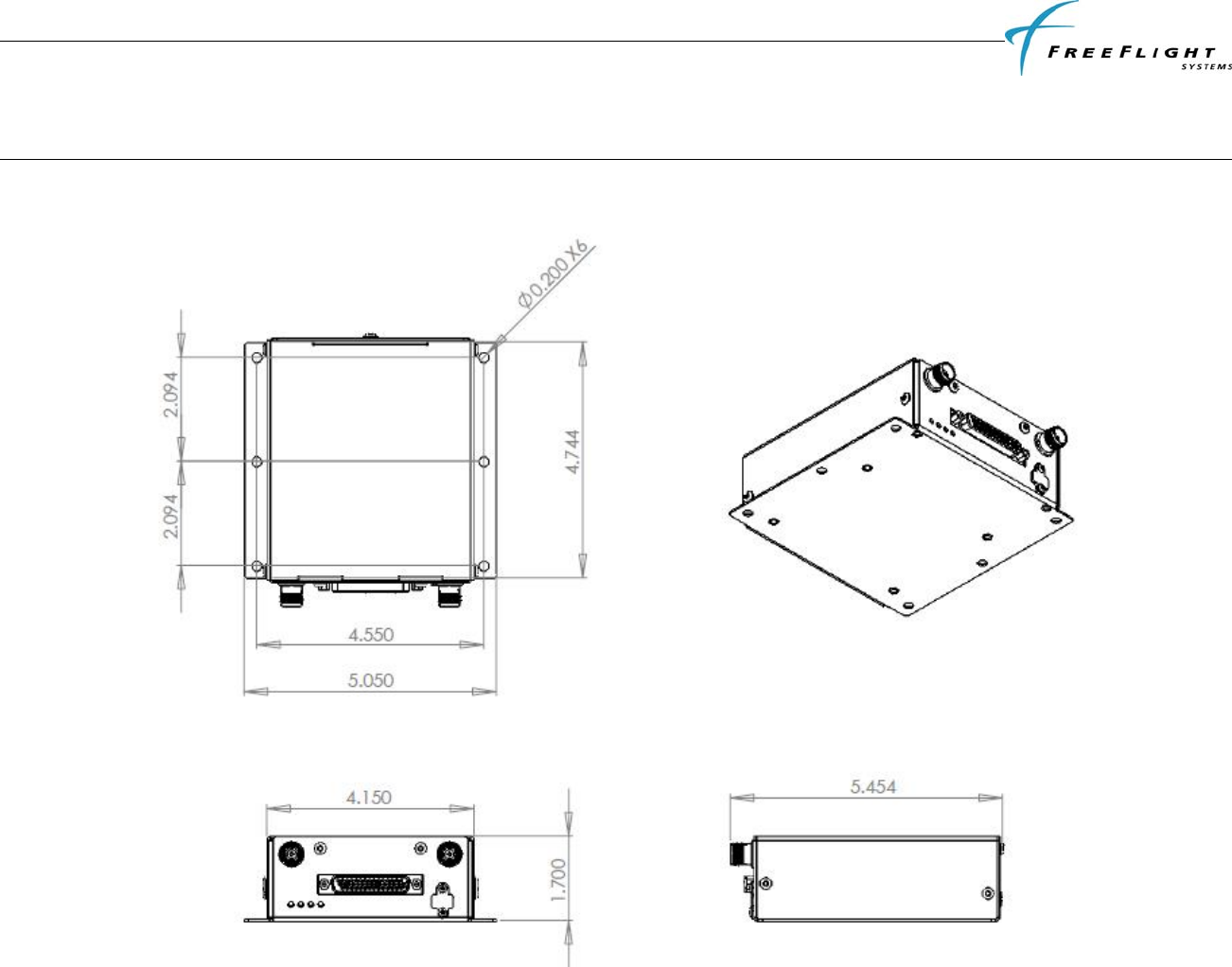
FDL-978-TX ADS-B
Transmitter Installation Manual
86960, Revision A September 1, 2011
V
III-1
SECTION VIII INSTALLATION DRAWINGS
8.1 FDL-978-TX TRANSMITTER DIMENSIONS
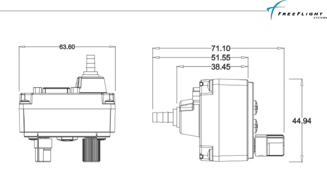
FDL-978-TX ADS-B
Transmitter Installation Manual
86960, Revision A September 1, 2011
V
III-2
8.2 TC-978 CONTROLLER DIMENSIONS
All dimensions in millimeters.
8.3 FRONT PANEL CUT-OUT OPTIONS
The TC-978 front panel controller can be fitted to either the compact mounting hole or a conventional 2¼ inch (57mm) instrument cut-out. The compact
mounting is a truncated 58 mm opening. Note that the mounting screws are NOT in the same location for the two options.
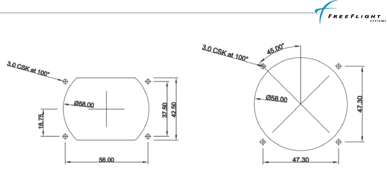
FDL-978-TX ADS-B
Transmitter Installation Manual
86960, Revision A September 1, 2011
V
III-3
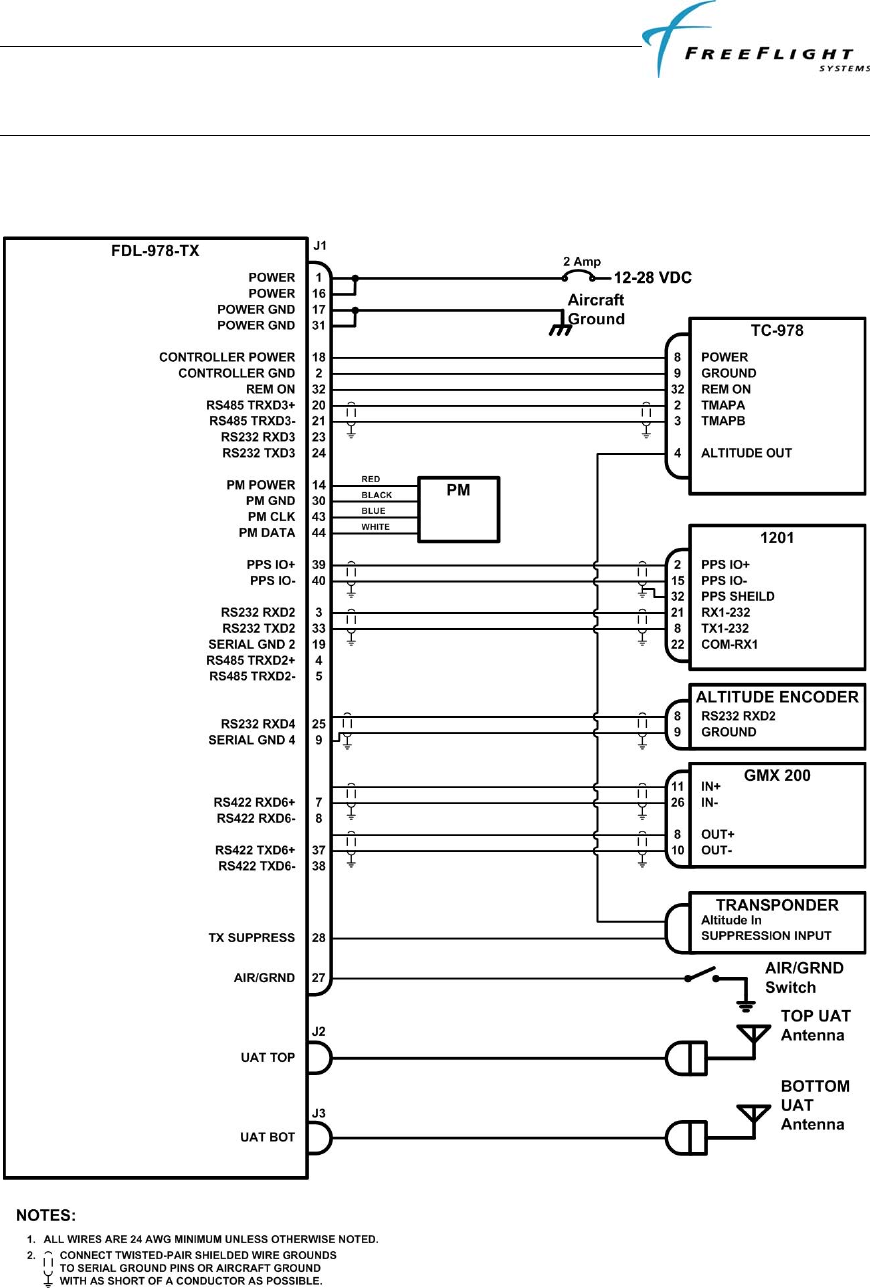
FDL-978-TX ADS-B
Transmitter Installation Manual
86960, Revision A September 1, 2011
IX-1
SECTION IX INTERCONNECT DIAGRAMS
9.1 FDL-978-TX INTERCONNECT DIAGRAM WITH 1201
GPS/SBAS SENSOR
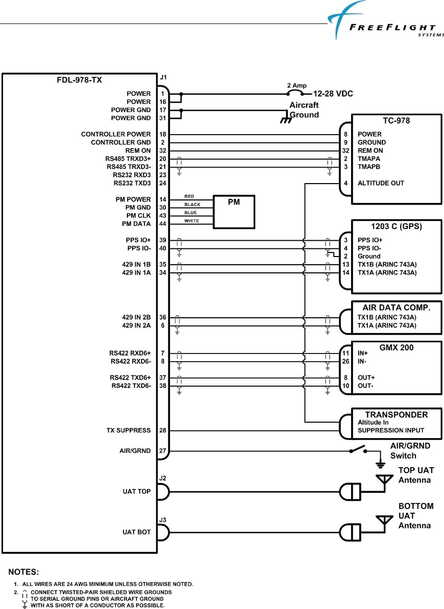
FDL-978-TX ADS-B
Transmitter Installation Manual
86960, Revision A September 1, 2011
IX-2
9.2 FDL-978-TX INTERCONNECT DIAGRAM WITH 1203/1203C
GPS/SBAS SENSOR

FDL-978-TX ADS-B
Transmitter Installation Manual
86960, Revision A September 1, 2011
IX-3
LIMITED WARRANTY
I. HARDWARE
FREEFLIGHT SYSTEMS, LTD. (“FREEFLIGHT”), 3700 Interstate 35 S, Waco, TX 76706, hereby warrants to the first retail purchaser only, that
hardware purchased hereunder will be free from defects in material and workmanship for a period of two (2) years from the date of installation, not to
exceed thirty (30) months from the date of shipment from FREEFLIGHT’s factory. Should defects be found, FREEFLIGHT at its option, will repair or
replace the product in which physical defects in materials or workmanship occur. The foregoing states the sole liability and obligation of FREEFLIGHT
arising out of this warranty, and such warranty is subject to the following CONDITIONS AND LIMITATIONS.
(A) The defect shall occur under normal use and service for which this product was intended. FREEFLIGHT shall not be obligated or liable under this
Warranty for defects which FREEFLIGHT’s examination discloses are due to: (1) tampering, (2) misuse, (3) abuse, (4) neglect, (5) improper storage or
maintenance, (6) use in a manner beyond which such equipment is normally intended to be used, (7) improper repair or poor workmanship by those who
are not authorized by FREEFLIGHT to repair the products or use of defective material by such unauthorized persons, and (8) any other cause except for
defects in material or workmanship caused by FREEFLIGHT.
(B) The warranty card supplied with the product must be completed and returned to FREEFLIGHT within 15 days of installation of the product in order
for this Warranty to become effective.
(C) The product is sold and installed by an authorized dealer. A list of all authorized FREEFLIGHT dealers may be obtained from FREEFLIGHT.
(D) The company must have received a copy of a completed FAA Form 337 covering installation of the product in the purchaser’s aircraft or equivalent
documentation showing installation of the product by the authorized FREEFLIGHT dealer.
(E) The product shall be returned to FREEFLIGHT via the dealer with transportation charges prepaid. After correction of the defects, the products will be
returned to the purchaser, transportation charges prepaid, except for returns to purchasers in foreign countries, which purchasers shall be responsible for
payment of such charges from the American Port of exit to purchaser’s place of business. The risk of loss or damage to all products in transit shall be
assumed by the party initiating the transportation of such products.
II. ITEMS NOT COVERED BY WARRANTY
EXCEPT FOR THE EXPRESS WARRANTIES GRANTED IN SECTIONS I AND II ABOVE, FREEFLIGHT MAKES NO OTHER WARRANTIES,
EXPRESSED OR IMPLIED, WITH RESPECT TO ITS PRODUCT AND DISCLAIMS THE SAME. FREEFLIGHT MAKES NO EXPRESS OR
IMPLIED WARRANTY WITH RESPECT TO THE DESIGN, ADEQUACY, ACCURACY, RELIABILITY, SAFETY OR CONFORMANCE WITH
GOVERNMENT STANDARDS OR REGULATION OF ANY FLIGHT PROCEDURE PRESCRIBED BY A GOVERNMENT AUTHORITY,
INCLUDING, BUT NOT LIMITED TO, ANY EXPRESS OR IMPLIED WARRANTY OF MERCHANTABILITY OR FITNESS FOR A
PARTICULAR PURPOSE. FURTHER, FREEFLIGHT MAKES NO WARRANTY, EXPRESS OR IMPLIED, WITH RESPECT TO THE
ADEQUACY, ACCURACY, RELIABILITY, SAFETY, OR CONFORMANCE WITH GOVERNMENT STANDARDS OR REGULATIONS, OF
ANY INFORMATION CONTAINED IN THE PRODUCT WHICH IS PUBLISHED BY OTHERS OR WHICH FREEFLIGHT OBTAINED FROM
OTHERS. FURTHER, FREEFLIGHT MAKES NO EXPRESS OR IMPLIED WARRANTY WITH RESPECT TO THE COMPLETENESS OF ANY
DATA, FLIGHT INFORMATION, OR FLIGHT PROCEDURE CONTAINED IN ITS PRODUCT. FREEFLIGHT DOES NOT INCLUDE ALL
AVAILABLE DATA IN ITS PRODUCT.
III. LIMITATIONS ON WARRANTY
THIS WARRANTY IS LIMITED TO THE ORIGINAL RETAIL PURCHASER, EXCEPT WHERE THE PRODUCT IS USED OR PURCHASED
PRIMARILY FOR THE PURCHASER’S PERSONAL OR FAMILY USE. THIS WARRANTY IS IN LIEU OF ALL OTHER WARRANTIES
EXPRESSED OR IMPLIED, INCLUDING WITHOUT LIMITATION, ANY IMPLIED WARRANTIES OF MERCHANTABILITY OR FITNESS
FOR A PARTICULAR PURPOSE, IF ANY, AND SAID IMPLIED WARRANTIES ARE HEREBY EXPRESSLY EXCLUDED AND DISCLAIMED.
WHERE THE PRODUCT IS USED OR PURCHASED PRIMARILY FOR THE PURCHASER’S PERSONAL OR FAMILY USE, ANY IMPLIED
WARRANTIES OF MERCHANTABILITY OR FITNESS FOR A PARTICULAR PURPOSE, IF ANY, ARE HEREBY EXPRESSLY LIMITED TO
TWO (2) YEARS FROM THE DATE OF PURCHASE OF THE PRODUCT. SOME STATES DO NOT ALLOW THE EXCLUSION OR
LIMITATION OF AN IMPLIED WARRANTY, OR OF INCIDENTAL OR CONSEQUENTIAL DAMAGES; THEREFORE, THE ABOVE
LIMITATIONS CONCERNING THE EXCLUSION OF IMPLIED WARRANTIES AND LIMITATIONS OF DAMAGES MAY NOT APPLY TO
YOU. THIS WARRANTY GIVES YOU SPECIFIC RIGHTS, AND YOU MAY ALSO HAVE OTHER RIGHTS WHICH VARY FROM STATE TO
STATE.
LIMITATION OF LIABILITY
FREEFLIGHT’S LIABILITY ARISING OUT OF THIS AGREEMENT SHALL NOT EXCEED THE AMOUNTS PAID BY YOU TO OBTAIN THE
PRODUCT. FREEFLIGHT SHALL NOT BE LIABLE FOR SPECIAL, CONSEQUENTIAL, INCIDENTAL OR OTHER TYPES OF DAMAGES,
INCLUDING WITHOUT LIMITATION, LOSS OF USE, LOST PROFITS, AND PERSONAL INJURY. FREEFLIGHT EXPRESSLY EXCLUDES
AND DISCLAIMS SUCH DAMAGES RESULTING FROM OR CAUSED BY, THE USE, OPERATION, FAILURE, MALFUNCTION OR DEFECT
OF ANY FREEFLIGHT PRODUCT, WHETHER OR NOT LIABILITY FOR SUCH DAMAGES IS DUE TO TORT (INCLUDING NEGLIGENCE),
CONTRACT, WARRANTY, OR STRICT LIABILITY. THESE LIMITATIONS WILL APPLY EVEN IF FREEFLIGHT OR AN AUTHORIZED
DEALER HAS BEEN ADVISED OF THE POSSIBILITY OF SUCH DAMAGE, AND NOTWITHSTANDING ANY FAILURE OF ESSENTIAL
PURPOSE OF ANY LIMITED REMEDY. YOU ACKNOWLEDGE THAT THE AMOUNT PAID FOR THE PRODUCT REFLECTS THIS
ALLOCATION OF RISK. SOME STATES DO NOT ALLOW THE LIMITATION OR EXCLUSION OF LIABILITY FOR INCIDENTAL OR
CONSEQUENTIAL DAMAGES, SO THE ABOVE LIMITATION OR EXCLUSION MAY NOT APPLY TO YOU. To obtain service under this
warranty contact: FreeFlight Systems at (254) 662-0000.

86960, Revision A September 1, 2011
© 2011
3700 Interstate 35 S.
Waco, TX 76706
1 (254) 662-0000
1 (800) 487-4662
http://www.freeflightsystems.com