FreeWave Technologies 218151431519 757-758MHz and 787-788MHz, 76kbps Over the Air Data Rate, Board Level, Licensed Band Radio, RS232 / RS485, 9-30 volts User Manual 760mhz
FreeWave Technologies Inc. 757-758MHz and 787-788MHz, 76kbps Over the Air Data Rate, Board Level, Licensed Band Radio, RS232 / RS485, 9-30 volts 760mhz
Exhibit D Users Manual per 2 1033 c3

760 MHz Data Transceiver Manual
LUM0000XX Rev A Version 1.0 i
FreeWave Technologies
760 MHz
Data Transceiver
Version 1.0
FreeWave Technologies, Inc.
1880 South Flatiron Court
Boulder, CO 80301
(303) 444-3862
(303) 786-9948 Fax
www.FreeWave.com

760 Mhz Data Transceiver Users Manual
LUM0000XX Rev A Version 1.0 ii
SPREAD SPECTRUM WIRELESS DATA TRANSCEIVER USER MANUAL
Copyright © 1995-2008 by FreeWave Technologies, Inc. All rights reserved. Published 2008.
WARRANTY
FreeWave Technologies warrants your FreeWave® Wireless Data Transceiver against defects in
materials and manufacturing for a period of two years from the date of shipment. In the event of a
Product failure due to materials or workmanship, FreeWave will, at its option, repair or replace the
Product. The Product must be returned to FreeWave upon receiving a Return Material Authorization
(RMA) for evaluation of Warranty Coverage.
In no event will FreeWave Technologies Inc., its suppliers, and its licensors be liable for any damages
arising from the use of or inability to use this Product. This includes business interruption, loss of
business information, or other loss which may arise from the use of this Product. Please be advised that
OEM customer’s warranty periods may vary.
Warranty Policy may not apply:
1. If Product repair, adjustments or parts replacements is required due to accident, neglect, unusual
physical, electrical or electromagnetic stress.
2. If Product is used outside of FreeWave specifications.
3. If Product has been modified, repaired or altered by Customer unless FreeWave specifically
authorized such alterations in each instance in writing. This includes the addition of conformal
coating.
[dupe of above]Special Rate Replacement Option
A special rate replacement option is offered to non-warranty returns or upgrades. The option to purchase
the replacement unit at this special rate is only valid for that RMA. The special replacement rate option
expires if not exercised within 30 days of final disposition of RMA.
RESTRICTED RIGHTS
Any product names mentioned in this manual may be trademarks, or registered trademarks of their
respective companies and are hereby acknowledged.
Information in this manual is subject to change without notice and is proprietary and confidential to
FreeWave Technologies, Inc.
This manual is for use by purchasers and other authorized users of the FreeWave® Wireless Data
Transceiver only.
No part of this manual may be reproduced or transmitted in any form or by any means, electronic or
mechanical, or for any purpose without the express written permission of FreeWave Technologies, Inc.
FreeWave’s Spread Spectrum Wireless Data Transceivers are designed and manufactured in the United
States of America.
Printed in the United States of America.

760 Mhz Data Transceiver Users Manual
LUM0000XX Rev A Version 1.0 iii
FCC NOTIFICATIONS
This equipment has been tested and found to comply with the limits for a Class A digital device, pursuant
to part 15 of the FCC Rules. These limits are designed to provide reasonable protection against harmful
interference when the equipment is operated in a commercial environment. This equipment generates,
uses, and can radiate radio frequency energy and, if not installed and used in accordance with the
instruction manual, may cause harmful interference to radio communications. Operation of this equipment
in a residential area is likely to cause harmful interference in which case the user will be required to
correct the interference at his own expense.
CAUTION: The LRS-760 series transceiver have maximum transmitted output power of 2W. It is
recommended that the transmit antenna be kept at least 37 cm away from nearby persons
to satisfy FCC RF exposure requirements.

760 Mhz Data Transceiver Users Manual
LUM0000XX Rev A Version 1.0 iv
Table of Contents
ABOUT FREEWAVE TRANSCEIVERS.................................................................................................................6
CHOOSING A LOCATION FOR THE TRANSCEIVERS....................................................................................6
CHOOSING POINT-TO-POINT OR POINT-TO-MULTIPOINT OPERATION ........................................................................7
QUICK START ON A POINT-TO-MULTIPOINT NETWORK ..........................................................................8
POINT-TO-MULTIPOINT OPERATION LEDS. ...............................................................................................................8
QUICK START ON A POINT-TO-POINT NETWORK........................................................................................9
POINT-TO-POINT OPERATION LEDS...........................................................................................................................9
SETTING UP A TRANSCEIVER ...........................................................................................................................10
OPERATION MODE....................................................................................................................................................10
BAUD RATE..............................................................................................................................................................12
CALL BOOK..............................................................................................................................................................15
RADIO TRANSMISSION CHARACTERISTICS ...............................................................................................................16
EDIT RADIO TRANSMISSION CHARACTERISTICS .......................................................................................................17
(0) FreqKey..........................................................................................................................................................17
Setting Xmit and Rcv Frequencies.......................................................................................................................17
(1) and (2) Max Packet Size and Min Packet Size...............................................................................................17
(3) Xmit Rate........................................................................................................................................................20
(4) RF Data Rate .................................................................................................................................................21
(5)RF Xmit Power................................................................................................................................................21
(6) Slave Security.................................................................................................................................................21
(7) RTS to CTS.....................................................................................................................................................21
(8) Retry Time Out...............................................................................................................................................22
(9) Lowpower Mode.............................................................................................................................................22
(A) High Noise.....................................................................................................................................................23
(C) Remote LED ..................................................................................................................................................23
SHOW RADIO STATISTICS .........................................................................................................................................24
Number of Disconnects........................................................................................................................................24
Antenna Reflected Power.....................................................................................................................................24
Transmit Current (mA) ........................................................................................................................................24
Average Noise Level ............................................................................................................................................24
Average Signal Level...........................................................................................................................................24
Overall Rcv Rate (%)...........................................................................................................................................24
Radio Temperature..............................................................................................................................................25
MULTIPOINT PARAMETERS ......................................................................................................................................26
EDIT MULTIPOINT PARAMETERS..............................................................................................................................26
(0) Number Repeaters..........................................................................................................................................26
(1) Master Packet Repeat ....................................................................................................................................26
(2) Max Slave Retry .............................................................................................................................................27
(3) Retry Odds .....................................................................................................................................................27
(4) DTR Connect..................................................................................................................................................27
(5) Repeater Frequency.......................................................................................................................................27
(6) Network ID.....................................................................................................................................................27
(8) MultiMaster Synch.........................................................................................................................................28
(9) 1 PPS Enable/Delay.......................................................................................................................................28
(A) Slave/Repeater...............................................................................................................................................28
(B) Diagnostics....................................................................................................................................................28
(C) Subnet ID.......................................................................................................................................................29
(D) Radio ID........................................................................................................................................................29
(E) Local Access ..................................................................................................................................................29
(G) Radio Name...................................................................................................................................................29

760 Mhz Data Transceiver Users Manual
LUM0000XX Rev A Version 1.0 v
OVERLAPPING MULTIPOINT NETWORKS ..................................................................................................................30
FACTORY DEFAULT SETTINGS.........................................................................................................................30
OPERATIONAL RS-422 AND RS-485 INFORMATION .................................................................................................32
RS-422 and RS-485 Full Duplex Pin-Outs ..........................................................................................................33
RS-485 Half Duplex Pin-Outs..............................................................................................................................33
RS232 PIN ASSIGNMENTS ........................................................................................................................................33
RF BOARD PINOUT...................................................................................................................................................34
FREEWAVE TECHNICAL SUPPORT ............................................................................................................................34
Channel Lists.......................................................................................................................................................35

760 Mhz Data Transceiver Users Manual
LUM0000XX Rev A Version 1.0 6
About FreeWave Transceivers
FreeWave transceivers operate in virtually any environment where RS232 data communications occur. A
pair of transceivers function as a 9-pin null modem cable. If the FreeWave transceivers are to be used in
an application where a null modem cable is used, such as communication between two computers, then
the FreeWave transceivers can be connected directly. If FreeWave transceivers are to be used to replace
a straight-through RS232 cable, then a null modem cable must be placed between the transceiver and
the DTE instrument to which it is connected.
Choosing a Location for the Transceivers
Placement of the FreeWave transceiver is likely to have a significant impact on its performance. The key
to the overall robustness of the radio link is the height of the antenna. In general, FreeWave units with a
higher antenna placement will have a better communication link. In practice, the transceiver should be
placed away from computers, telephones, answering machines and other similar equipment. The RS232
cable included with the transceiver usually provides ample distance for placement away from other
equipment. To improve the data link, FreeWave Technologies offers directional antennas with cable
lengths ranging from 3 to 200 feet. When using an external antenna, placement of that antenna is critical
to a solid data link. Other antennas in close proximity are a potential source of interference; use the Radio
Statistics to help identify potential problems. The Show Radio Statistics page is found in option 4 in the
Main Menu. An adjustment as little as 2 feet in antenna placement can resolve some noise problems. In
extreme cases, band pass filter may reduce the out-of-band noise.

760 Mhz Data Transceiver Users Manual
LUM0000XX Rev A Version 1.0 7
Choosing Point-to-Point or Point-to-MultiPoint Operation
A Point-to-Point network is limited to one Master and one Slave transceiver.
In a Point-to-MultiPoint network (also referred to as MultiPoint network) the transceiver, designated as a
Master, is able to simultaneously communicate with numerous Slaves. In its simplest form, a MultiPoint
network functions with the Master broadcasting its messages to all Slaves and the Slaves responding to
the Master when given data by the device connected to the data port.
It is important to note the differences between Point-to-Point and MultiPoint networks. In a Point-to-Point
network all packets are acknowledged, whether sent from the Master to the Slave or from the Slave to the
Master. In a MultiPoint network, outbound packets from the Master to Slaves are sent a set number of
times determined by the user. The receiving transceiver will accept the first packet received that passes
the 32 bit CRC. However, the packet is not acknowledged. On the return trip to the Master, all packets
sent by the Slave are acknowledged or retransmitted until they are acknowledged. Therefore, the return
link in a MultiPoint network is generally very robust.
Traditionally, a MultiPoint network is used in applications where data is collected from many instruments
and reported back to one central site. As such, the architecture of such a network is different from Point-
to-Point applications. The number of radios in a MultiPoint network is influenced by the following
parameters:
1. Size of the blocks of data. The longer the data blocks, the smaller the network capacity.
2. Baud rate.
3. The amount of contention between Slaves. Polled Slaves vs. timed Slaves.
For example, if the network will be polling Slaves once a day to retrieve sparse data, several hundred
Slaves could be configured to a single Master. However, if each Slave will be transmitting data at greater
levels, then fewer Slaves should be linked to the Master. The overall network will be closer to capacity
with fewer Slaves.
For examples and additional information on data communication links, see the section Examples
of Data Communication Links later in this document.

760 Mhz Data Transceiver Users Manual
LUM0000XX Rev A Version 1.0 8
Quick Start on a Point-to-MultiPoint Network
The following is a quick start guide for setting up two transceivers in Point-to-MultiPoint mode. This mode allows for a
Master to communicate with several Slaves simultaneously.
1. Connect the transceiver to the serial port of a computer either through a serial cable or via the diagnostics
cable. Make sure to connect the radio to a power source (typically, 9 to 30 VDC).
2. Open up a HyperTerminal session.
Use the following settings in connecting with HyperTerminal
Connect to COMx (where 'x' is the number of the com port being connected to)
Set data rate to 19,200, data bits - 8, Parity- none, Stop bits – 1, Flow control – none.
3. Press the Setup button on the radio. If using the diagnostics cable, press Shift-U (capital U).
The three lights on the board should all turn green, indicating Setup mode.
The main menu will appear on the screen.
4. Press 0 to get into the Operation Mode menu.
Press 2 to set the radio as a point to MultiPoint Master.
OR, Press 3 to set the radio as a point to MultiPoint Slave.
Press Esc to get back to Main menu.
5. Press 1 in the main menu to change the Baud Rate.
The baud rate must be changed to match the baud rate of the device that the radio is to be attached to.
Press Esc to get back to Main menu.
6. At the Main Menu, press 3.
Set FreqKey, Max Packet Size, Min Packet Size, RF Data rate identical on all radios in the network.
Note: Changing these values may help to eliminate interference from other FreeWave networks.
Press Esc to get back to Main menu.
7. At the Main Menu, press 5.
Set the Network ID value to any value between 1 and 4095, except 255.
Make sure this value is the same on every radio in the network.
Point-to-MultiPoint Operation LEDs.
Master Slave
Condition Carrier Detect
(CD) Transmit
(TX) Clear to
Send (CTS) Carrier
Detect
(CD)
Transmit
(TX) Clear to
Send
(CTS)
Powered, not linked Solid red
bright Solid red
dim Off Solid red
bright Off Blinking
red
Slave linked to Master,
no data Solid red
bright Solid red
dim Off Solid
green Off * Solid red
bright
Slave linked to Master,
Master sending data to
Slave
Solid red
bright Solid red
dim Off Solid
green Off * Solid red
bright
Slave linked to Master,
Slave sending data to
Master
Solid green
RCV data
or Solid red
bright
Solid red
dim Intermittent
flash
redo
Solid
green Intermittent
flash
redo
* Solid red
bright
Master with diagnostics
program running Solid red
bright Solid red
dim Intermittent
flash
redo
Solid
green Intermittent
flash
redo
* Solid red
bright
* Clear to Send LED will be solid red with a solid link, as the link weakens the Clear to Send LED light on the Slave
will begin to flash.

760 Mhz Data Transceiver Users Manual
LUM0000XX Rev A Version 1.0 9
Quick Start on a Point-to-Point Network
When purchased as a pair, the FreeWave® Wireless Data Transceivers are shipped from the factory pre-
configured to operate in Point-to-Point applications. To establish communications between a pair of
FreeWave Wireless Data Transceivers just received from the factory:
1. Connect the transceiver to the instrument with the RS232 cable and also attach power. The
cable supplied with enclosed transceivers (except Waterproof) is a 9-pin male serial; professional
board level transceivers will need a separate programming cable (sold separately).
2. Set the Modem mode in each transceiver. One should be set as a Point-to-Point Master (Mode
0) and the other set as a Point-to-Point Slave (Mode 1).
3. Set the baud rate on each transceiver to match the baud rate of the instrument to which it is
attached. Please note, when setting the transceiver's baud rate, its RS232 data rate is set. The
baud rate does not have to be on the same setting for the two transceivers.
4. Edit the Call Book. Enter the Slave serial number in the Master’s Call Book. Enter the Master’s
Serial number in the Slave’s Call Book, or disable Slave Security (in the Slave).
5. Connect antennas to the transceiver. Any FreeWave transceiver may be operated without an
antenna for bench-top testing without concern for damaging the product. Noise potential may be
reduced on the bench by lowering the Xmit power.
6. Shortly after both transceivers are plugged in, they should establish a communications link with
each other and the connection is complete. Using the table below, verify that the radios are
operating as expected.
Point-to-Point Operation LEDs
Master Slave
Condition Carrier
Detect
(CD)
Transmit
(TX) Clear to
Send (CTS) Carrier
Detect (CD) Transmit
(TX) Clear to
Send (CTS)
Powered, no link Solid red
bright Solid red
bright Solid red
bright Solid red
bright Off Blinking red
Linked, sending
sparse data Solid
green Intermittent
flash
redo
Intermittent
flash
redo
Solid
green Intermittent
flash
redo
Intermittent
flash
redo
Master calling
Slave Solid red
bright Solid red
dim Solid red
bright Solid red
bright Off Blinking red
Mode 6 - waiting
for ATD command Solid red
bright Off Blinking
red Solid red
bright Off Blinking red
Setup Mode Solid
green Solid
green Solid green Solid
green Solid
green Solid
green
760 Mhz Data Transceiver Users Manual
LUM0000XX Rev A Version 1.0 10
Setting up a Transceiver
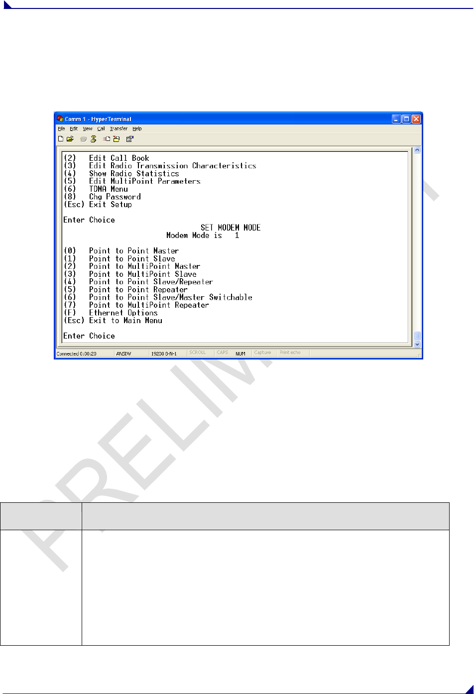
Operation Mode
The Operation Mode option designates the method FreeWave transceivers use to communicate with
each other. FreeWave transceivers operate in a Master to Slave configuration. Before the transceivers
can operate together, they must be set up to properly communicate.
In a Point-to-Point configuration, Master or Slave Mode may be used on either end of the communication
link without performance degradation. When setting up the transceiver, remember that a number of
parameters are controlled by the settings in the Master. Therefore, deploying the Master on the
communications end where it will be easier to access is advised, but not necessary.
Note: Operation Modes not described below are not to be used in the FreeWave 760 MHz Data
Transceiver.
Operation
Mode Description
Point-to-Point
Master (0) This mode designates the transceiver as the Master in Point-to-Point mode. The
Master may call any or all Slaves designated in its Call Book.
In Point-to-Point mode the Master determines the setting used for most of the
radio transmission characteristics, regardless of the settings in the Slave. The
settings not determined by the Master are: RF Xmit Power, Slave Security, Retry
Time Out, and the Hop Table settings.
A quick method of identifying a Master is to power the transceiver. Prior to
establishing a communication link with a Slave, all three of the Master’s LEDs
will be solid red.

760 Mhz Data Transceiver Users Manual
LUM0000XX Rev A Version 1.0 11
Point-to-Point
Slave (1) This mode designates the transceiver as a Slave in Point-to-Point mode. The
Slave communicates with any Master in its Call Book.
When functioning as a Slave, the Entry to Call feature in the transceiver’s Call
Book is not operational. The Call Book may be bypassed in the Slave by setting
Slave Security to 1. See the Slave Security section later in this manual.
Point–to-
MultiPoint
Master (2)
This mode designates the transceiver as a Master in MultiPoint mode. This
mode allows one Master transceiver to simultaneously be in communication with
numerous Slaves.
A Point-to-MultiPoint Master communicates only with other transceivers
designated as Point-to-MultiPoint Slaves.
Point-to-
MultiPoint
Slave (3)
This mode designates the transceiver as a Slave in MultiPoint mode. This mode
allows the Slave to communicate with a MultiPoint Master. The Slave may
communicate with its Master.
760 Mhz Data Transceiver Users Manual
LUM0000XX Rev A Version 1.0 12
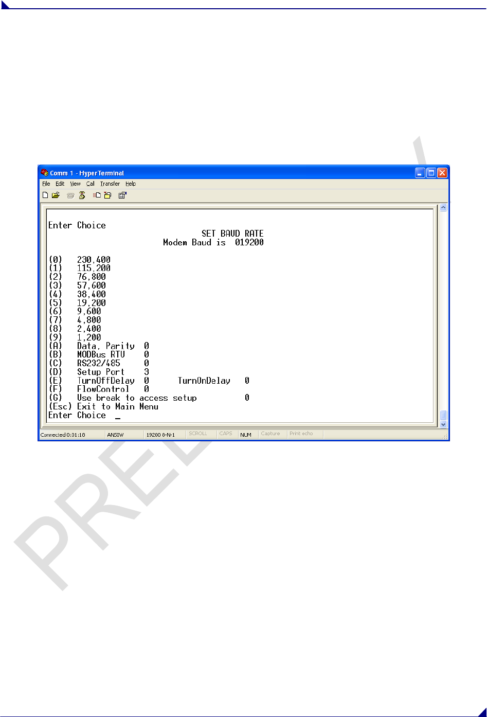
Baud Rate
This setting is the communication rate between the transceiver and the instrument to which it is
connected. It is important to note that this is independent of the baud rate for the other transceiver(s) in
the network. For example, a pair of transceivers may be used in an application to send data from remote
process instrumentation to an engineer's computer. In this application, the baud rate for the transceiver
on the instrumentation might be set to 9600, and the transceiver on the engineer’s computer might be set
to 57,600.
Set Baud Rate
1. Select the appropriate baud rate to match the attached device.

760 Mhz Data Transceiver Users Manual
LUM0000XX Rev A Version 1.0 13
Baud Rate Description
Actual Baud Rate
(selections 0-9) The actual baud rate for the transceiver’s data port.
It is desirable to set the baud rate to the highest level supported by the device to
which it is connected. In certain circumstances, however, this may actually result
in slower data communications.
Data, Parity There are six data word length and parity configurations available to be used with
FreeWave transceivers. The default setting is 0 (8, N, 1) and is the most commonly
used serial communications protocol. When Data, Parity are selected from the
Baud Rate menu, a prompt to enter a value for Data, Parity displays. The
following describes each option:
Menu Setting Data Bits Parity Stop Bits
0 8 None 1
1 7 Even 1
2 7 Odd 1
3 8 None 2
4 8 Even 1
5 8 Odd 1
FlowControl This menu specifies the hardware flow control for the Data port. The options for 0-3
are described below.
Menu Port Additional Information
0 None Default - Uses software control (XON XOFF)
1 RTS
2 DTR
3 DOT
Modbus RTU
Support for Modbus RTU protocol is available. The default setting for Modbus
RTU is 0 (Not Enabled).
To enable the Modbus RTU mode:
1. In the Set Baud Rate menu enter (B) and then select 1
2. In the Set MultiPoint Parameters menu, set Master Packet Repeat to 3.
Note: When using the transceiver in Modbus RTU mode, the Master Packet
Repeat must be set to 3 regardless of whether the network is in Point-to-
Point or MultiPoint mode. The Modbus RTU mode must be selected when
transceivers are configured in RS485 or RS422 mode.

760 Mhz Data Transceiver Users Manual
LUM0000XX Rev A Version 1.0 14
Serial Interface
In products for which the protocol of the data port is software selectable, use this
menu to set the protocol of the data port. In the TTL RF board product this setting
must be "0".
Menu Protocol Additional Information
0 RS232 Also used for TTL transceivers.
1 RS422 Modbus RTU mode must be enabled. See above.
2 RS485 Modbus RTU mode must be enabled. See above.
3 DOT Special for the Department of Transportation.
Note: When DOT mode is enabled, the TimeDelay settings operate the same as
in the RS485/422 mode.
Note: RS4xx mode must have Modbus RTU enabled, and TurnoffDelay set to at
least 4.
Setup Port
Note: DO NOT change this setting unless the correct programming cable is
available for the new setting.
This setting determines which port, Main or Diagnostics, is used to enter the Setup
Main Menu.
Menu Port Additional Information
1 Main Only The terminal is connected to the Main Data Port.
2 Diagnostics Only The terminal is connected to the Diagnostic Port.
3 Both Ports The terminal may be connected to either port.
Setup mode is invoked by sending a "U" (capital) to the Diagnostics port or by
pressing/toggling the Set-up button/switch, if available. OEM boards may also
enter Setup when Pin 2 is grounded.
The Main Data Port is the RS232 port. The OEM modules use a 2-row, 2 mm
female connector. The diagnostic cable for this port (ASC2009DC) is available
from FreeWave.
TurnOn/OffDelay
TurnOnDelay- Sets the delay between when the line drivers are turned on and
when the data leaves the data port. This setting can be adjusted for a 1-9 mS
delay.
TurnOffDelay- This setting specifies the time after the end of transmission of a
character to the RS485 bus that the transceiver stops driving the bus and releases
the bus to other devices. The units are ¼ of a character with a range of 0-9. An
entry of 4 means a delay equivalent to the duration of a full character. Default is
zero delay.
For data rates of 1200 bits/S or slower, avoid setting the TurnoffDelay parameter
higher than 4. At those rates the functionality of the microprocessor changes so
that a TurnoffDelay of 5 will have the same effect as if set to 1, and a setting of 6
will have the same effect as 2, and so on.
Note: TurnOffDelay must be set to a value of at least 4 for RS4xx operation.
760 Mhz Data Transceiver Users Manual
LUM0000XX Rev A Version 1.0 15
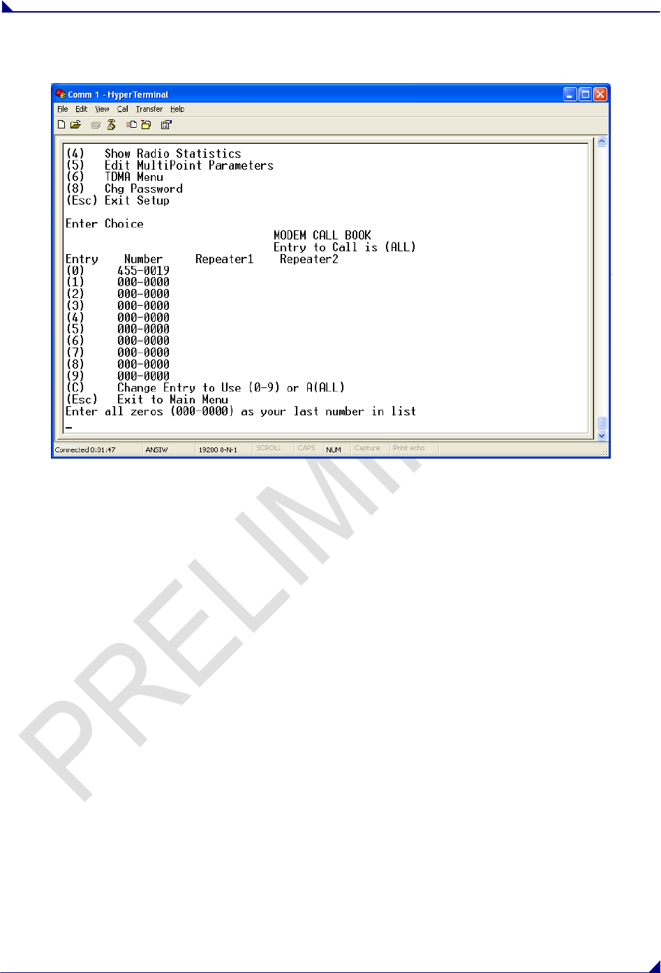
Call Book
The Call Book is required to be used in Point-to-Point networks. The instructions provided in this section
are for Point-to-Point mode only.
Using the Call Book offers both security and flexibility in determining how FreeWave transceivers
communicate with each other.
Three settings must be made for two FreeWave transceivers to communicate in Point-to-Point mode:
1. The Master’s serial number must be listed in the Slave's Call Book or Slave Security is turned off
in the Slave.
2. The Slave’s serial number must be listed in the Master's Call Book.
3. The Master must be programmed to call the Slave.
The Call Book allows users to incorporate up to 10 FreeWave transceivers, and designate which Slave the
Master will call. To set the Entry to Call option, enter C at the prompt, followed by the menu number
corresponding to that Slave. To call any available Slave in the list, enter C then enter A to direct the Master
to Call All.
760 Mhz Data Transceiver Users Manual
LUM0000XX Rev A Version 1.0 16
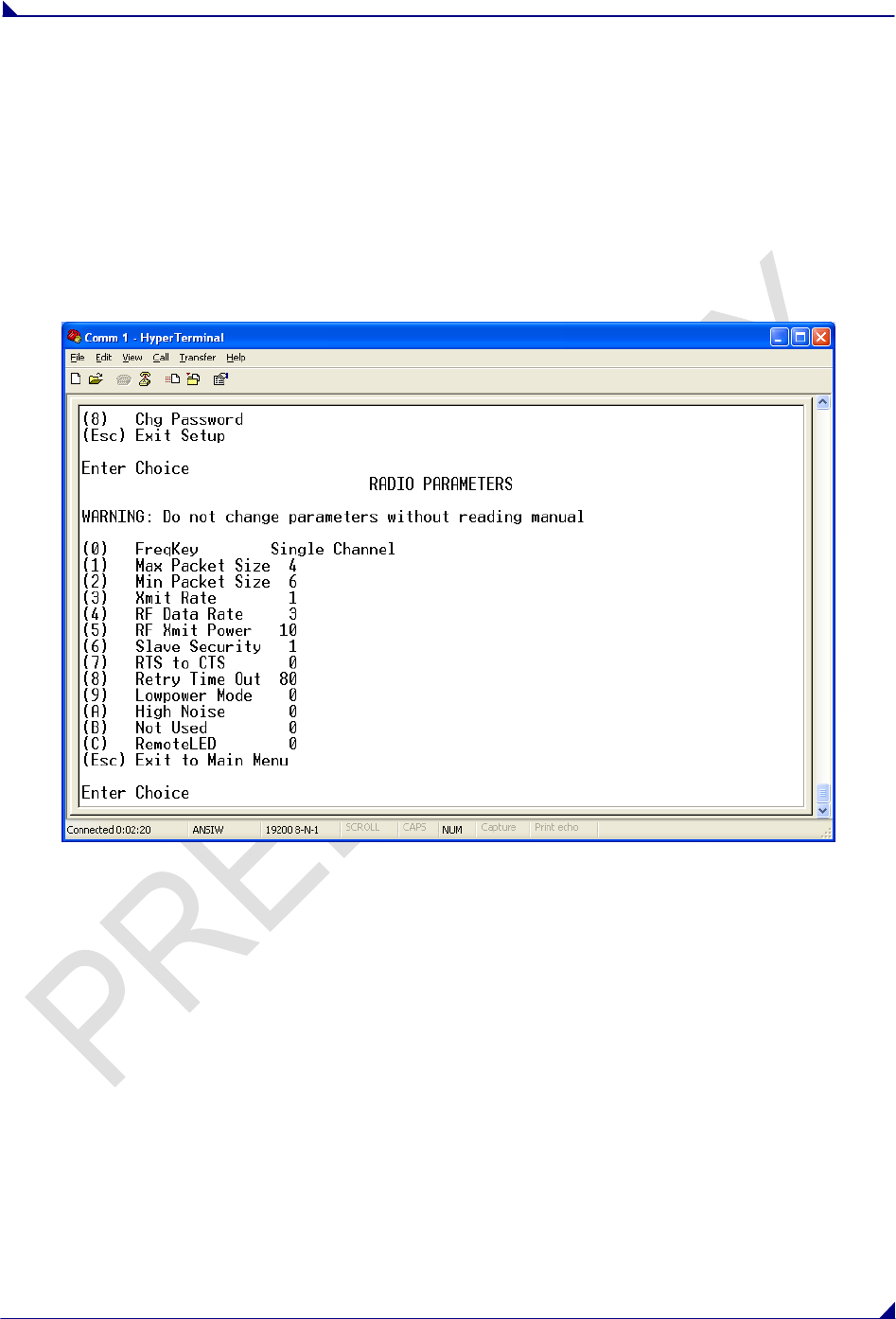
Radio Transmission Characteristics
The Edit Radio Transmission Characteristics option allows the user to modify several different parameters
in the transceiver. Many of these parameters must be maintained throughout the network for proper
functionality.
Note: This menu is only for the sophisticated user who has a good understanding of the principles of
radio data transmission.
The settings for the Slave(s) not determined by the Master are RF Xmit Power, Slave Security, Retry
Time Out and Hop Table Size, Hop Table Version, and Hop Table Offset.
760 Mhz Data Transceiver Users Manual
LUM0000XX Rev A Version 1.0 17
Edit Radio Transmission Characteristics
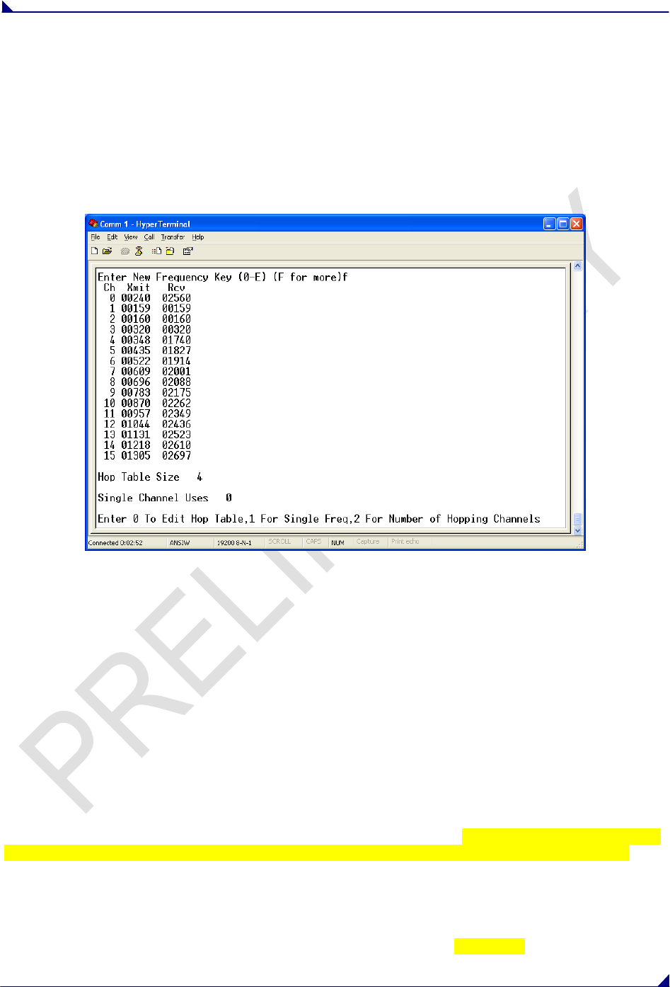
(0) FREQKEY
The FreqKey parameter should always be set to operate in single channel mode.
To set FreqKey for Single Channel, select option 0 “FreqKey”, then select option F for more options.
Select option 1 for Single Channel, then select the appropriate Frequency Channel.
SETTING XMIT AND RCV FREQUENCIES
The 760MHz Data Transceiver operates by transmitting on one frequency and receiving on a second
unique frequency.
In order to program these channels, please refer to the Channel and Frequency lists at the end of this
document.
Select option 0 Edit Hop Table, and then select the appropriate Channel Number to edit. Enter the
appropriate Xmit channel number, from the Channel List, and press enter, and then enter the appropriate
Rcv channel number, from the Channel List.
Select option 1 For Single Channel, then select the appropriate Channel number to use the frequencies
just programmed.
(1) AND (2) MAX PACKET SIZE AND MIN PACKET SIZE
The Max and Min Packet Size settings and the RF Data Rate determine the number of bytes in the
packets. Throughput can be enhanced when packet sizes are optimized. In Point-to-Point mode, the Max
and Min Packet Settings will not have material impact on throughput unless 115.2 KBaud is desired.
However, this may have an impact on latency. For example, if small amounts of data are sent and large
packet sizes are selected, there would be a certain amount of time “wasted” between each packet.
The following 6 tables provide the information to determine optimum setting values.
The default settings for Max and Min packet size and RF Data Rate are 8, 9, and 3, respectively.
760 Mhz Data Transceiver Users Manual
LUM0000XX Rev A Version 1.0 18
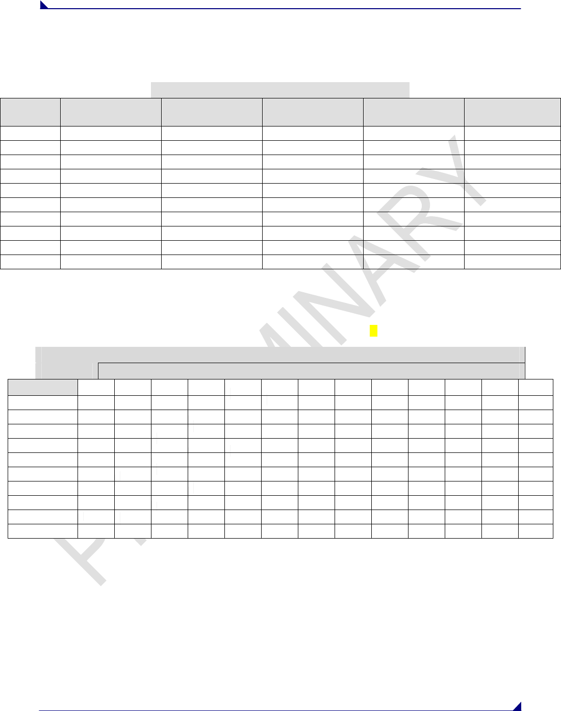
The following table defines the Minimum packet size in bytes by way of charting the Min Packet Size
setting versus the RF Data Rate setting. Using the default settings, the actual minimum packet size, in
bytes, is x.
Minimum Packet Size Definition
Min
Setting Min Packet Size
RF Data Rate = 1 Min Packet Size
RF Data Rate = 2 Min Packet Size
RF Data Rate = 3 Min Packet Size
RF Data Rate = 4 Min Packet Size
RF Data Rate = 5
0
1
2
3
4
5
6
7
8
9
The following table defines the Maximum packet size in bytes by way of charting the Min Packet Size
setting versus the Max Packet Size setting where the RF Data Rate is set to 1.
Using the default settings, the actual maximum packet size, in bytes, is x.
Maximum Packet Size Definition with RF Date Rate of 1
Max Setting
Min Setting 0 1 2 3 4 5 6 7 8 9 A B C
0
1
2
3
4
5
6
7
8
9
760 Mhz Data Transceiver Users Manual
LUM0000XX Rev A Version 1.0 19
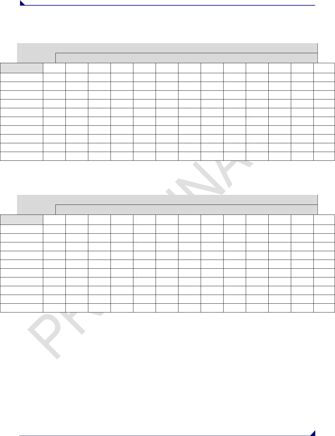
The following table defines the Maximum packet size in bytes by way of charting the Min Packet Size
setting versus the Max Packet Size setting where the RF Data Rate is set to 2.
Maximum Packet Size Definition with RF Date Rate of 2
Max Setting
Min Setting 0 1 2 3 4 5 6 7 8 9 A B C
0
1
2
3
4
5
6
7
8
9
The following table defines the Maximum packet size in bytes by way of charting the Min Packet Size
setting versus the Max Packet Size setting where the RF Data Rate is set to 3.
Maximum Packet Size Definition with RF Date Rate of 3
Max Setting
Min Setting 0 1 2 3 4 5 6 7 8 9 A B C
0
1
2
3
4
5
6
7
8
9
760 Mhz Data Transceiver Users Manual
LUM0000XX Rev A Version 1.0 20
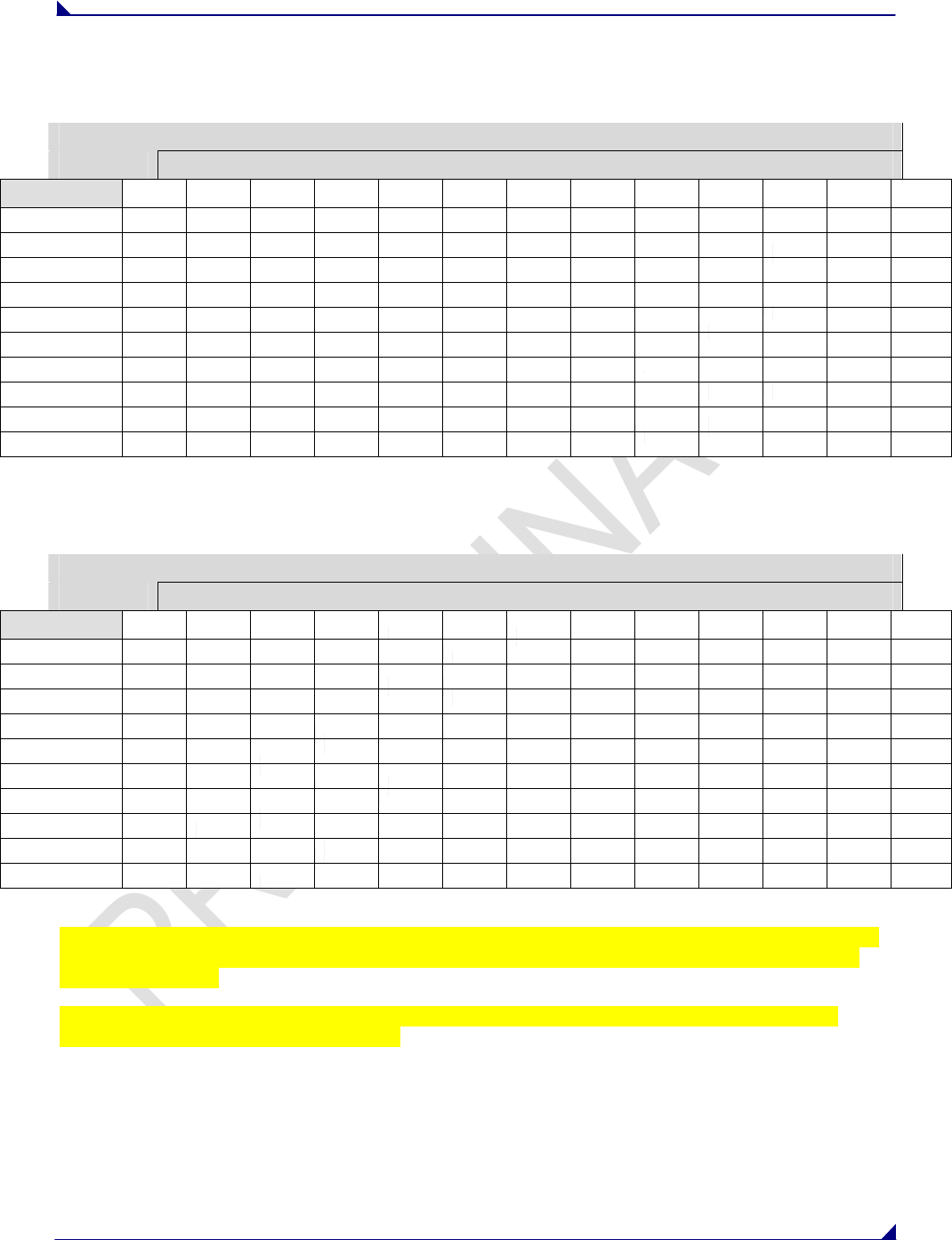
The following table defines the Maximum packet size in bytes by way of charting the Min Packet Size
setting versus the Max Packet Size setting where the RF Data Rate is set to 4.
Maximum Packet Size Definition with RF Date Rate of 4
Max Setting
Min Setting 0 1 2 3 4 5 6 7 8 9 A B C
0
1
2
3
4
5
6
7
8
9
The following table defines the Maximum packet size in bytes by way of charting the Min Packet Size
setting versus the Max Packet Size setting where the RF Data Rate is set to 5.
Maximum Packet Size Definition with RF Date Rate of 5
Max Setting
Min Setting 0 1 2 3 4 5 6 7 8 9 A B C
0
1
2
3
4
5
6
7
8
9
Referencing the default settings, the Master will transmit up to 172 bytes on every hop. If fewer than 172
bytes are transmitted, the balance is allocated to the Slave's transmission, plus the quantity in the Min
Packet Size Setting.
For example, if a Master transmits 100 bytes, the Slave will then have a total of 116 bytes available
(72(“leftover bytes”) + 44 (Min packet size))
(3) XMIT RATE
There are two settings for the Transmit Rate parameter. The setting for normal operation of the
transceiver is a Transmit Rate 1. Transmit Rate 0 is useful to qualitatively gauge signal strength in Point
to Point mode. When set to Transmit Rate 0, the transceivers will transmit back and forth continuously
regardless if they have any actual data. In Point-to-Point operation, Transmit Rate 0 should be used only
as a diagnostic tool and not for normal operation. The strength of the signal may be gauged by the Clear

760 Mhz Data Transceiver Users Manual
LUM0000XX Rev A Version 1.0 21
to Send LED. A solid red CTS LED indicates a strong signal; a blinking CTS LED indicates a weaker
signal.
(4) RF DATA RATE
FreeWave transceivers have five settings for the RF Data Rate (1, 2, 3, 4, 5 ). RF Data Rate should not
be confused with the serial port Baud Rate.
Setting 2 should be used when the transceivers are close together and data throughput needs to be
optimized. Setting 3 should be used when the transceivers are farther away and a solid data link is
preferred over data throughput.
Note: In MultiPoint networks, the RF Data Rate must be set identically in all transceivers. Any
transceiver with an RF Data Rate different from the Master will not establish a link.
In Point to Point networks the Master’s settings take precedence over the Slave.
RF Data Rate Setting Occupied Bandwidth Modulation Level Throughput
1 50kHz GFSK
2 25kHz 4-level GFSK
3 25kHz GFSK
4 12.5kHz 4-level GFSK
5 12.5kHz GFSK
(5)RF XMIT POWER
The RF Xmit Power parameter allows the user to control the output transmit power up to two watts
(+33dBm).
(6) SLAVE SECURITY
Slave security is a feature which allows Slave transceivers to accept transmissions from a Master not
included in the Call Book. The default setting is 0 (Slave Security enabled) which means, only Masters in
the Slaves’ Call Book may link to that Slave.
Slave Security may be disabled (setting of 1) allowing any Master to call the Slave. Slave Security has no
effect in Point-to-MultiPoint networks where the Network ID is not set to 255.
Slave Security must be set to 1 when the unit is operating in Mode 6 Slave/Master switchable or a Point-
to-Point network where the Slave may need to accept calls from more than 10 different Masters. When
Slave Security is set to 1, the transceiver will accept calls from any other FreeWave transceiver.
Additional network security measures may be taken to prevent unauthorized access, such as changing
default settings for FreqKey, Hop Table or Frequency Zones.
(7) RTS TO CTS
Menu selection RTS to CTS in the Radio Parameters menu provides the option of allowing the RTS line
on the Master transceiver to control the CTS line of the Slave. This pass-through control can be enabled
in both Point-to-Point and Point-to-MultiPoint. In MultiPoint networks, the Master RTS line will control all
Slaves’ CTS lines. When enabled, the CTS line ceases to function as flow control. It is not recommended
to enable this feature when operating at RS-232 speeds above 38.4kB.

760 Mhz Data Transceiver Users Manual
LUM0000XX Rev A Version 1.0 22
The default setting of 0 disables this function, where as a setting of 1 enables RTS-CTS control.
RTS-CTS setting 2 is described in detail in the application note #5437 DTR to CTS Line Alarm Feature.
With an RTS to CTS setting of 1, the Master senses the RTS line prior to all scheduled packet
transmissions. If the state has changed, the Master will then transmit a message to the Slave with the
new status. This transmission will occur regardless of data being sent. If data is ready to be sent, the
RTS status message will be sent in addition to the data. In Point-to-Point mode, the Master will continue
sending the new status message until it receives an acknowledgment from the Slave. In MultiPoint mode,
the Master will repeat the message the number of times equal to the Master Packet Repeat value in the
MultiPoint Parameters menu.
Master transmit times are completely asynchronous to the occurrence of any change of the RTS line; the
latency time from RTS to CTS is variable. The Max and Min Packet Size parameters in the Radio
Parameter menu determine this duration. Setting both parameters to their maximum value of 9 will
produce a maximum latency time of approximately 21 ms. At the minimum settings for Max and Min
Packet Size (0), the time will be approximately 5.9 ms. Please note that this latency can increase
significantly if packets are lost between the Master and Slave. In Point-to-MultiPoint mode, there is no
absolute guarantee that the state change will be communicated to all Slaves in the unlikely event that all
repeated packets from the Master do not get through to all Slaves.
Note: If DTRConnect is enabled and set to 2, the RTS to CTS feature will not work.
Note: If the DTRConnect is enabled and set to 1, RTS to CTS mode takes precedence over the
functionality of the CTS line on the Slave relating to the DTRConnect feature.
Note: The RTS to CTS option is only available in RS232 mode.
(8) RETRY TIME OUT
The Retry Time Out parameter in a Slave sets the delay the unit will wait before dropping the connection
to a Master in MultiPoint mode. The factory default is set at the maximum of 255. The maximum setting
means that if 1 packet in 255 is sent successfully from the Master to the Slave, the link will be maintained.
The minimum setting is 8. This allows a Slave to drop a connection if less than 1 in 8 consecutive packets
is successfully received from the Master.
On the other hand, the function in the Master is effectively the same. With a setting of 255, the Master
will allow a Slave to stay connected as long as 1 packet in 255 is successfully received at the Master.
The Retry Time Out parameter is useful when a MultiPoint network has a roving Master or Slave(s). As
the link gets weaker, a lower setting will allow a poor link to break in search of a stronger one.
Note: Setting Retry Time Out to 20 is recommended in areas where several FreeWave networks exist.
This setting will allow Slaves to drop the connection if the link becomes too weak, while at the
same time prevent errant disconnects due to interference from neighboring networks.
While intended primarily for MultiPoint networks, the Retry Time Out parameter may also be modified in
Point-to-Point networks. However, the value in Point-to-Point mode should not be set to less than 151.
(9) LOWPOWER MODE
The Lowpower Mode feature allows a MultiPoint Slave to consume less power. This is achieved primarily
by dimming the transceiver's LEDs. When set to 2 through 31, the transceiver will sleep between slots.
For example, at a setting of 2 the transceiver sleeps 1 out of 2 slots; at a setting of 3 the transceiver
sleeps 2 out of 3 slots, and so on.
The following table shows the changes at different Lowpower Mode settings. The actual current draw
depends on many factors. The table below gives only a qualitative indication of supply current savings. A
low number reduces latency and a high number reduces current consumption.
760 Mhz Data Transceiver Users Manual
LUM0000XX Rev A Version 1.0 23
Setting Description
0 Lowpower, disabled
1 LEDs dimmed, transceiver remains awake, transceiver is listening to the
Master’s transmissions on every slot, and transceiver’s data port is shut
down if the RTS line is deasserted (low). In this case, the transceiver
needs to be awakened before it will be able to send data to the Master.
2 LEDs dimmed, transceiver sleeps every other slot
3 LEDs dimmed, transceiver sleeps 2 of 3 slots
4-31 LEDs dimmed, transceiver sleeps the number of slots corresponding to
the setting. For example, with a setting of 31 the transceiver sleeps 30 of
31 slots.
IMPORTANT NOTES
1. Lowpower Mode is used only in MultiPoint Slaves using serial protocol. Power savings occur only
when the Slave is linked. There are no power savings when the Slave is transmitting data.
Lowpower Mode is of little value when a Slave has a constant, high throughput. MCUSpeed must
be set to ‘0’ and RF Data Rate must be set to ‘3’ for Lowpower Mode to operate properly.
2. To communicate to an RS232 port of a transceiver that is in Lowpower Mode, the RTS line must
be held high to wake it up. The transceiver will wake up within approximately 20 milliseconds of
when RTS goes high.
3. If the RTS line on the Slave is held high, the transceiver will remain in normal operation
regardless of the Lowpower Mode setting. Once RTS is dropped the transceiver reverts to the
Lowpower Mode.
If the transceiver has the DTRConnect option set to 1 or 2 and if the Lowpower Mode enabled (set to 1-
31), the RTS line on the transceiver must be asserted for the ‘DTRConnect’ feature to operate properly.
(A) HIGH NOISE
The High Noise Option is useful in determining if out of band interference is affecting a radio link. A
setting of 1 will provide a reduction of gain in the front end circuit thereby decreasing the affect of any out
of band noise. The results will be seen as a lower signal value and a much lower noise value (as found in
Radio Statistics or Diagnostics). If the noise is not reduced by a greater amount than the signal, the
interference is most likely an in band issue.
When a noise problem is shown to be helped by way of the High Noise option, chances are that the noise
may be further squelched by use of a band pass filter available for sale from FreeWave Technologies.
(C) REMOTE LED
This setting enables the user to connect Remote LED’s through the diagnostics port.
Setting Description Notes
0 Board LED’s Default. Only on board LEDs are enabled.
1 Board and Remote LED’s Onboard LED’s are enabled as well as
Remote LED’s through the Diagnostic port.
2 Remote LED’s
On board LED’s are disabled. Remote LED’s
are enabled through the Diagnostic port.
Note: When using Remote LED’s the center (TX) LED will not turn Green when in Setup mode. This line
is not pinned out.
Current Draw
More
Less

760 Mhz Data Transceiver Users Manual
LUM0000XX Rev A Version 1.0 24
Show Radio Statistics
Radio Statistics in the Main Menu allows the user to view data transmission statistics gathered by the
transceiver during the most recent session. This is valuable when the user needs to know the signal
strength and noise levels of the link. Statistics are gathered during each data link and are reset when the
next link begins. See display below.
NUMBER OF DISCONNECTS
Any time the link between the Master and the Slave is broken and the radios lose Carrier Detect, it is
recorded in the Number of Disconnects value. The value indicates the total number of disconnects that
have occurred from the time the transceiver is powered on until the radio is put into Setup mode. Under
ideal operating conditions, the number of disconnects should be 0. One or more disconnects may indicate
a weak link, the presence of severe interference problems or loss of power to any of the radios in the link.
ANTENNA REFLECTED POWER
This is a measurement of the transmitted power that is reflected back into the transceiver from
mismatched antennas or cables, or loose connections between the transceiver and antenna. A reading
of 0-5 is good; 5-30 is acceptable; 30+ indicates that the connections should be inspected for loose
connections and cable quality.
TRANSMIT CURRENT (MA)
This measures the current draw of the transmitter in milliamps. Refer to Transceiver specs for typical
values.
AVERAGE NOISE LEVEL
The average noise level indicates the level of background noise and interference at this transceiver. The
number is an average of the noise levels measured at each frequency in the transceiver’s frequency hop
table. The individual measurement values at each frequency hop channel are shown in the frequency
table. Pressing the Enter key when the Radio Statistics menu is displayed, accesses the frequency table.
Ideally, noise levels should be below 70 J units and the difference between the average signal level and
average noise level should be 26 or more. Noise levels significantly higher than this are an indication of a
high level of interference that may degrade the performance of the link. High noise levels can often be
mitigated with band pass filters, antenna placement or antenna polarization.
AVERAGE SIGNAL LEVEL
The average signal level indicates the level of received signal at this transceiver. For each of these, the
signal source is the transceiver that transmits to it. The number is an average of the received signal levels
measured at each frequency in the transceiver's frequency hop table. The individual measurement values
at each frequency hop channel are shown in the frequency table. Pressing the Enter key when the Radio
Statistics menu is displayed accesses the frequency table. For a reliable link, the margin should be at
least 26 J units. Low Average Signal Levels can often be corrected with higher gain antennas and better
antenna placement.
Note: Please consult the install manual for antenna and FCC requirements.
OVERALL RCV RATE (%)
The Overall Receive Rate measures the percentage of data packets that were successfully transmitted
from the Master to the Slave on the first attempt. A number of 75 or higher indicates a robust link that will
provide very good performance even at high data transmission rates. A number of 15 or lower indicates a
weak or marginal link that will provide lower data throughput. An Overall Receive Rate of 100% will

760 Mhz Data Transceiver Users Manual
LUM0000XX Rev A Version 1.0 25
provide approximately 100 KBaud of bandwidth with an RF Data Rate setting of 3 and approximately 150
KBaud of bandwidth with an RF Data Rate of 2.
RADIO TEMPERATURE
The Radio Temperature value is the current operating temperature of the transceiver in degrees Celsius.
For proper operation, a FreeWave transceiver must be in the temperature range of -40° to +75° C. Some
of the transceivers are only tested to 0° C. See transceiver specification papers for details.
760 Mhz Data Transceiver Users Manual
LUM0000XX Rev A Version 1.0 26
MultiPoint Parameters
When installing MultiPoint networks it is important to do some up front planning. Unlike Point-to-Point
networks, a Point-to-MultiPoint network requires several parameters are set consistently on all
transceivers in the network. This includes RF data rate, Min and Max Packet Size, and FreqKey.
Note: If several independent MultiPoint networks are to be located in close proximity the planning
becomes more critical. In such cases, it becomes very important to include as much frequency
and time diversity as possible through use of different FreqKey, Min and Max Packet Size, and
Hop Table settings. In some instances the use of the MultiMaster Synch option may be required.
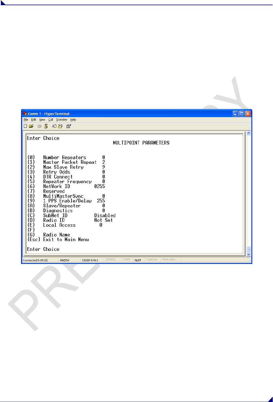
Edit MultiPoint Parameters
Selecting (5) Edit MultiPoint Parameters from the main menu displays the following window:
(0) NUMBER REPEATERS
Repeaters are not available in the FreeWave LRS-760 Data Transceivers.
(1) MASTER PACKET REPEAT
In a Point-to-MultiPoint network, Slaves do not acknowledge transmissions from the Master. If Slaves did
acknowledge all data transmissions, in a large network, the Master would soon become overwhelmed
with acknowledgments from the Slaves. Without acknowledgements, 100% confidence every Slave has
received every packet cannot be met. To address this issue, the user may modify the Master Packet
Repeat setting, assigning a value between 0 (the packet is transmitted once) to 9 (the packet is
transmitted 10 times). For networks with solid RF links, this parameter should be set to a low value such
as 1 or 2. If a network has some weak or marginal links it should be set with higher values. If a Slave
receives a good packet from a Master more than once it will discard the repeated packets
Increasing the Master Packet Repeat setting will increase the probability of a packet getting through, but
will also increase latency in the network because each packet from the Master is being sent multiple

760 Mhz Data Transceiver Users Manual
LUM0000XX Rev A Version 1.0 27
times. Therefore, it is important to find the optimal mix between network robustness, throughput, and
latency. In general, a setting of 2 to 3 will work well for most well designed networks.
Note: The Master Packet Repeat may be set to 0 if the user software is capable of, or requires
acknowledgment. In this case if a packet sent by the Master and not received by the Slave, the
user software will control the retries as needed.
(2) MAX SLAVE RETRY
The Max Slave Retry setting defines how many times (0 to 9) the Slave will attempt to retransmit a packet
to the Master before beginning to use a back-off algorithm (defined by the Retry Odds setting). Slave
retries will stop when an acknowledgement is received from the Master.
(3) RETRY ODDS
While packets transmitted from the Master to the Slaves in a MultiPoint network are not acknowledged,
packets transmitted from Slaves to the Master are. It is possible, that more than one Slave will attempt to
transmit to the Master at the same time. Therefore, it is important that a protocol exists to resolve
contention for the Master between Slaves. This is addressed through parameters (2) Max Slave Retry
and (3) Retry Odds. Once the Slave has unsuccessfully attempted to transmit the packet the number of
times specified in Max Slave Retry, it will attempt to transmit to the Master on a random basis. The Retry
Odds parameter determines the probability that the Slave will attempt to retransmit the packet to the
Master; a low setting will assign low odds to the Slave attempting to transmit. Conversely, a high setting
will assign higher odds. An example of how this parameter might be used would be when considering two
different Slaves in a MultiPoint network, one with a strong RF link and the other with a weak RF link to the
Master. It may be desirable to assign higher Retry Odds to the Slave with the weaker link to give it a
better chance of competing with the closer Slave(s) for the Master's attention.
When Retry Odds = 0, after the Slave has exhausted the number of retries set in the Max Slave Retry
parameter and still not gained the Master’s attention, the Slave’s data buffer will be purged.
(4) DTR CONNECT
With the setting of 0 in the Slave, the transceiver will transmit when RS232 data is received. A setting of
1 will form a Point-to-Point link with the Master when the DTR line is high. With a setting of 2, the
transceiver will transmit in bursts. This mode is valuable when a network has many low data rate devices
and it is desirable to increase overall network capacity.
Note: If ‘DTRConnect’ is set to 1 and the ‘RTS to CTS’ function is enabled on the radio, then ‘RTS to
CTS’ takes precedence over ‘DTRConnect’.
Note: If ‘DTRConnect’ is set to ‘2’ and ‘RTS to CTS’ is enabled, then ‘RTS to CTS’ is ignored. The
transceiver has two separate transmit and receive user data buffers. These buffers are 2 Kbytes
each. In case of a buffer overflow, the transceiver will output unpredictable data.
(5) REPEATER FREQUENCY
Repeaters are not available in the FreeWave 760 MHz Data Transceivers.
(6) NETWORK ID
Network ID allows MultiPoint networks to be established without using the Call Book. The default setting
of 255 enables the Call Book. To enable Network ID the value must be set between 0 and 4095
(excluding 255). Since Network ID does not use serial numbers, MultiPoint Masters may be replaced
without reprogramming all of the Slaves in the network. Slaves will link with the first Master that it hears
that has a matching Network ID. The Network ID function should be used in conjunction with the Subnet
ID feature (If necessary).

760 Mhz Data Transceiver Users Manual
LUM0000XX Rev A Version 1.0 28
Without having the serial numbers in the Call Book, a Slave may establish communications with different
Masters, though not at the same time. This is very useful in mobile MultiPoint applications.
(8) MULTIMASTER SYNCH
MultiMaster Synch is reserved for applications, in both Point-to-Point and MultiPoint modes, with
concentrations of Master units where it is necessary to reduce interference between the Masters. Please
contact FreeWave Technologies for more information.
(9) 1 PPS ENABLE/DELAY
The 1 PPS Enable/Delay option allows the radio network to propagate a 1PPS signal from the Master to
all Slaves in a MultiPoint network. When this parameter is enabled a properly generated pulse applied on
the DTR line of the Master will provide a 1 PPS pulse on the CD line of any Slave in the network. To use
the 1 PPS Enable/Delay feature the steps outlined below must be followed:
1PPS Enable/Delay Setup:
1. The 1 PPS Enable/Delay parameter must be set to 0 in the Master.
2. The Master must have a 1 PPS pulse on the DTR pin.
3. The 1 PPS Enable/Delay parameter on the Slaves must be enabled. Slaves are calibrated at the
factory.
Calibrating a Slave in 1PPS Enable/Delay mode
1. Trigger an oscilloscope on the 1 PPS pulse on the DTR line of the Master.
2. Monitor the CD line of the Slave.
3. If the timing on the Slave differs from the Master it may be adjusted via the value in the Slave's 1
PPS Enable/Delay parameter. The difference in time between each incremental integer value is
542.534nS. Changing the parameter to higher values decreases the Slave time delay and
changing the parameter to lower values increases the time delay.
When properly calibrated the CD line of a Slave radio will output a pulse that goes high for about 2mS in
synch with the 1 PPS pulse on the Master radio. The output on the Slave will occur within 20
microseconds of the input to the Master.
Note: When 1 PPS is enabled, the Master must have a 1 PPS pulse on its DTR pin, otherwise the RF
network will not function.
(A) SLAVE/REPEATER
Repeaters are not available in the FreeWave 760 MHz Data Transceivers.
(B) DIAGNOSTICS
This option provides diagnostics data to be viewed at the Master in parallel with application data. The
diagnostic program MUST be run from the Master transceiver. Diagnostics requires the following:
1. Diagnostics set to (1 to 128) in the Master.
2. A second computer or serial connection to run the diagnostics software.
3. A diagnostics cable. (Available from FreeWave Technologies.)
4. Diagnostics software. (Available on the User Manual and System Tools CD.)
For more information on Diagnostics, please contact FreeWave Technical Support at (303) 381-9200.

760 Mhz Data Transceiver Users Manual
LUM0000XX Rev A Version 1.0 29
(C) SUBNET ID
Subnet ID is not to be used in the FreeWave LRS-760 Data Transceivers.
(D) RADIO ID
Option (D) allows a transceiver to be designated with an arbitrary, user selectable, 4 digit number which
identifies the transceiver in diagnostics mode.
(E) LOCAL ACCESS
Local Access is not to be used at this time.
(G) RADIO NAME
Option (G) allows the user to set a unique 20 character Radio name.

760 Mhz Data Transceiver Users Manual
LUM0000XX Rev A Version 1.0 30
Overlapping MultiPoint Networks
Overlapping MultiPoint networks may be set up effectively with FreeWave transceivers when several key
parameters are set correctly. Overlapping MultiPoint networks are defined as networks using different
Masters which share or overlap in a specific geographic area. It may also include co-located transceivers
configured into different networks.
Co-located MultiPoint networks require the following parameters be unique for each network:
Network ID, unless using Call Book
Frequency Key
Max Packet Size
Min Packet Size
For more questions about the installation of Point-to-MultiPoint networks, please contact FreeWave
Technical Support at (303) 444-3862.
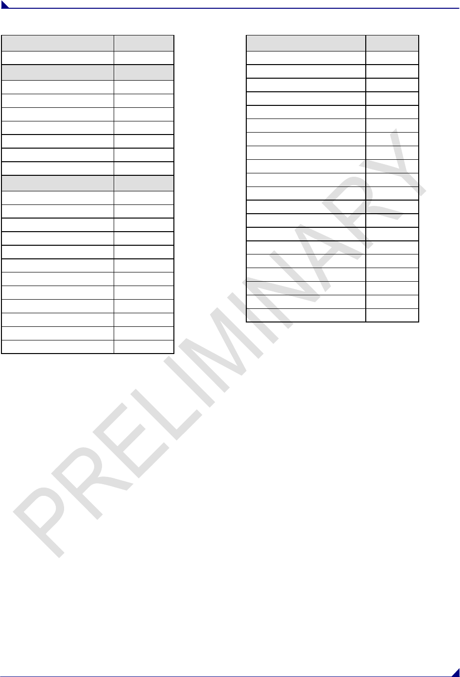
Factory Default Settings
FreeWave serial transceivers are shipped from the factory with the following Default Settings:
760 Mhz Data Transceiver Users Manual
LUM0000XX Rev A Version 1.0 31
Operation Mode Default
Point to Point Slave 1
Set Baud Rate Default
Baud Rate 115200
(A) Data Parity 0
(B) Modbus RTU 0
(C) RS232/485 0
(D) Setup Port 3
(E) TurnOffDelay/OnDelay 0/0
(F) Flow Control 0
Radio Parameters Default
(1) MAX PACKET SIZE 8
(2) MIN PACKET SIZE 9
(3) XMT RATE 1
(4) RF DATA RATE 3
(5) RF XMT POWER 10
(6) SLAVE SECURITY 0
(7) RTS TO CTS 0
(8) RETRY TIMEOUT 255
(9) LOW POWER MODE 0
(A) High Noise 0
(B) MCU Speed 0
(C) Remote LED 0
MultiPoint Parameters Default
(1) MASTER PACKET REPEAT 2
(2) MAX SLAVE RETRY 9
(3) RETRY ODDS 9
(4) DTR CONNECT 0
(6) NETWORK ID 255
(7) RESERVED -
(8) MULTI MASTER SYNC 0
(9) 1 PPS ENABLE DELAY 255
(B) DIAGNOSTICS 0
(D) RADIO ID Not Set

760 Mhz Data Transceiver Users Manual
LUM0000XX Rev A Version 1.0 32
Additional Transceiver information
This section contains additional important information about FreeWave transceivers. The following topics
are included in this section:
Operational RS422 and RS-485 Information
RS232 Pin Assignments
OEM Board Pin Assignments
Operational RS-422 and RS-485 Information
For both RS-422 and RS-485, the FreeWave transceiver can drive 32 standard unit loads and loads the
bus with only 1/8 unit load. This means the user can tie up to 256 devices on the bus if all of the line
receivers have 1/8 unit load.
RS-422 is used for 4-wire or full duplex communication with one Master and multiple Slaves. The
FreeWave Master transceiver keeps the line driver asserted at all times. The maximum line length is
4,000 feet using 2, 120 ohm twisted pair cables with a 5th wire for data common.
RS-485 full duplex using 4 wire plus common is the same as RS-422, except the system can have
multiple Masters on the bus.
The most common operation of RS-485 is a two-wire comprised of a 120 ohm impedance single twisted
pair. In this system the loading of the FreeWave transceiver is as described above which allows up to 256
1/8 unit load units on the bus. Maximum line length is also 4,000 feet with a third wire required for data
common. The FreeWave transceiver will check the line to be certain no other device is transmitting before
enabling the line driver for data transmission.
When setting the transceiver to RS-485, enable Modbus and set Master Packet Repeat to 3 in the
transceiver(s) that will use RS-485. Also set TurnOff Delay to 4.
The TurnOffDelay setting in the menu is used to control the length of time the transmitter driver stays
asserted after data transmission has finished. This is needed to allow the last transmitted character to
reach the end of a long line and is normally set to one character length of time. This setting also allows 3
complete reflections to the end of the line to ensure the ringing on the line has fully dampened before
releasing the bus to another device. Shorter line lengths may use shorter delays, but four one-quarter-
character delay times are recommended. In Modbus, a TurnOffDelay setting of 0 will cause internal timing
errors.
There is no provision for hand shaking in any of the above modes of operation, so data rates of 57.6
KBaud and above are not recommended without a protocol that can handle error detection properly.
760 Mhz Data Transceiver Users Manual
LUM0000XX Rev A Version 1.0 33
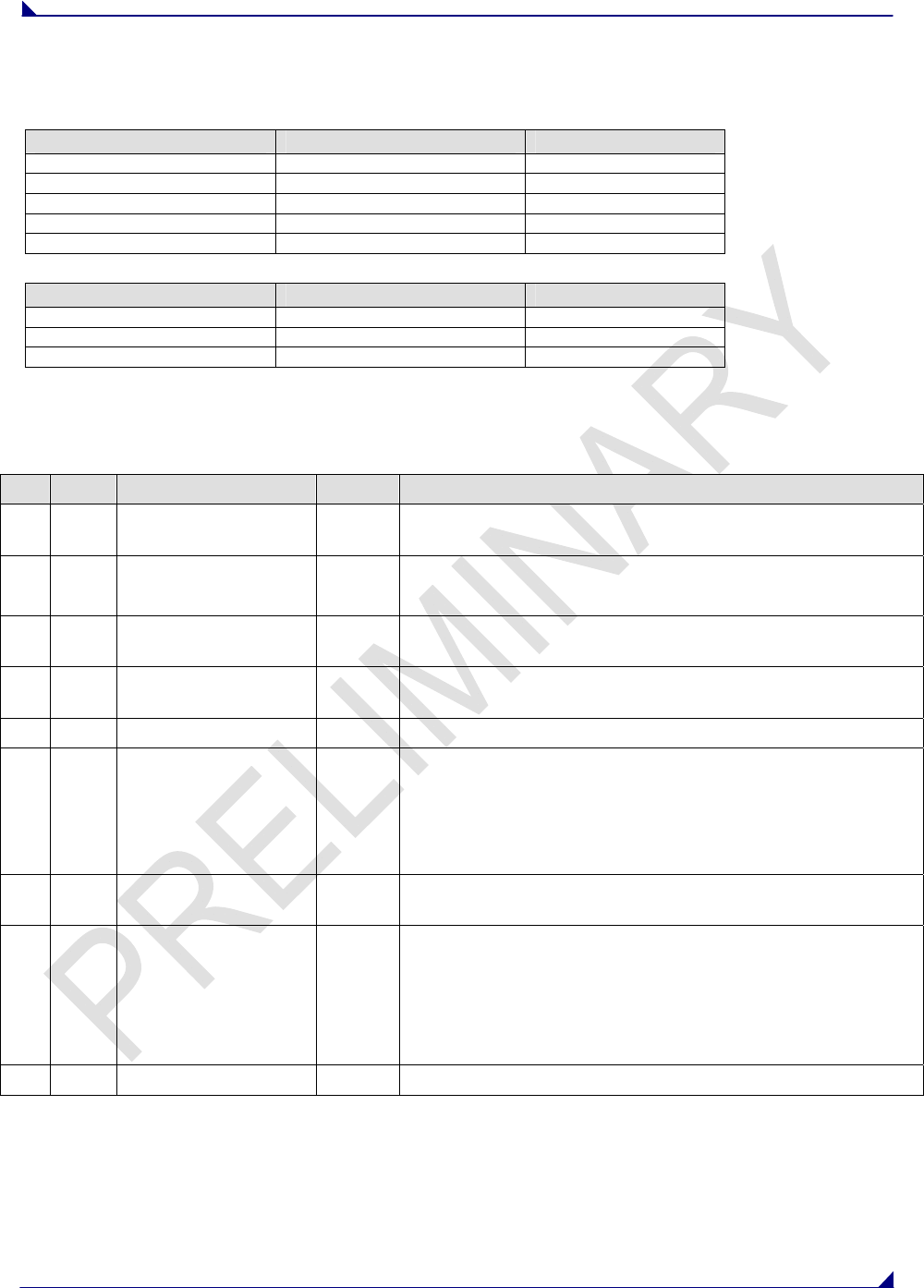
RS-422 AND RS-485 FULL DUPLEX PIN-OUTS
Function Bare Board Pin Number DE-9 Pin Number
RX+ 7 3
RX- 9 7
TX+ 5 2
TX- 10 8
Signal Ground 4 or 6 5
RS-485 HALF DUPLEX PIN-OUTS
Function Bare Board Pin Number DE-9 Pin Number
Wire to both pins for Bus + Short 5 and 7 Short 2 and 3
Wire to both pins for Bus - Short 9 and 10 Short 7 and 8
Signal Ground 4 or 6 5
RS232 Pin Assignments
Pin Assignment Signal Definition
1 CD Carrier Detect Output Used to show an RF connection between transceivers.
2 TX Transmit Data Output Used to transmit data bits serially from the transceivers to the
system device.
3 RX Receive Data Input Used to receive data bits serially from the system device
connected to the transceivers.
4 DTR Data Terminal Ready Input Used only in transceivers in Point-to-Point Slave/Master
switchable mode or for DTR Connect.
5 GND Ground Signal return for all signal lines shared with Pin 9.
6 DSR Data Set Ready Output Always high when the radio is powered from the 2.5mm
power connector. Indicated power is on to the radio. Also,
this pin can be used for +12Volts when powering the
transceivers directly through the RS-232 port.
Note: This is not used on the OEM module.
7 RTS Request to Send Input The transceiver does not recognize RTS for flow control. RTS
is used as a control line in RTS/CTS mode.
8 CTS Clear to Send Output This signal is used to tell the system device connected to the
transceiver that the transceiver is ready to receive data.
When asserted, the transceiver will accept data, when
deasserted the transceiver will not accept data. This should
always be used for data rates above 38.4KB or there will be a
risk of lost data if an RF link is not very robust.
9 GND Ground Signal return for all signal lines shared with Pin 5.

760 Mhz Data Transceiver Users Manual
LUM0000XX Rev A Version 1.0 34
RF Board Pinout
The 760 MHZ Series transceivers are available in both TTL and RS232 versions.
The TTL versions use reverse polarity from standard RS-232 at 0 to 5 Volt levels. All pin descriptions and
pin numbering are the same as the RS232 version. The RS232 versions use standard RS232 polarity and
voltage levels for all of the RS232 signal lines (DTR, Transmit Data, Receive Data, Carrier Detect, RTS,
and Clear to Send) and TTL standard polarity and voltage level for the Interrupt pin.
Pin 1: B+ Power input.
Pin 2: Interrupt (INT) – Input – A 0 volt level on this pin will switch the radio into Setup mode.
Pin Assignment Color on ACS3610xx cable
1 B+ input Red
2 Interrupt (temporarily ground to invoke menu) Brown
3 Data Terminal Ready (DTR) Orange
4 Ground Black
5 Transmit Data (TXD) Yellow
6 Ground Black
7 Receive Data (RXD) Green
8 Carrier Detect (DCD) Blue
9 Request to Send (RTS) Violet (purple)
10 Clear to Send (CTS) Gray
Note: Pin 1 on the board level transceiver is the pin farthest from the three LEDs and pin 10 is closest
to the LEDs.
FreeWave Technical Support
For up-to-date troubleshooting information check the Support page at www.FreeWave.com.
FreeWave provides Technical Support, Monday through Friday, 8:00 AM to 5:00 PM, Mountain Time
(GMT -7) Call us toll-free at 1-800-548-5616 or factory direct after hours at 303-444-3862 or email us
at moreinfo@FreeWave.com

760 Mhz Data Transceiver Users Manual
LUM0000XX Rev A Version 1.0 35
CHANNEL LISTS
Channel# Freq Channel# Freq Channel# Freq Channel# Freq
0 757 46 757.2875 92 757.575 138 757.8625
1 757.00625 47 757.29375 93 757.58125 139 757.86875
2 757.0125 48 757.3 94 757.5875 140 757.875
3 757.01875 49 757.30625 95 757.59375 141 757.88125
4 757.025 50 757.3125 96 757.6 142 757.8875
5 757.03125 51 757.31875 97 757.60625 143 757.89375
6 757.0375 52 757.325 98 757.6125 144 757.9
7 757.04375 53 757.33125 99 757.61875 145 757.90625
8 757.05 54 757.3375 100 757.625 146 757.9125
9 757.05625 55 757.34375 101 757.63125 147 757.91875
10 757.0625 56 757.35 102 757.6375 148 757.925
11 757.06875 57 757.35625 103 757.64375 149 757.93125
12 757.075 58 757.3625 104 757.65 150 757.9375
13 757.08125 59 757.36875 105 757.65625 151 757.94375
14 757.0875 60 757.375 106 757.6625 152 757.95
15 757.09375 61 757.38125 107 757.66875 153 757.95625
16 757.1 62 757.3875 108 757.675 154 757.9625
17 757.10625 63 757.39375 109 757.68125 155 757.96875
18 757.1125 64 757.4 110 757.6875 156 757.975
19 757.11875 65 757.40625 111 757.69375 157 757.98125
20 757.125 66 757.4125 112 757.7 158 757.9875
21 757.13125 67 757.41875 113 757.70625 159 757.99375
22 757.1375 68 757.425 114 757.7125
23 757.14375 69 757.43125 115 757.71875
24 757.15 70 757.4375 116 757.725
25 757.15625 71 757.44375 117 757.73125
26 757.1625 72 757.45 118 757.7375
27 757.16875 73 757.45625 119 757.74375
28 757.175 74 757.4625 120 757.75
29 757.18125 75 757.46875 121 757.75625
30 757.1875 76 757.475 122 757.7625
31 757.19375 77 757.48125 123 757.76875
32 757.2 78 757.4875 124 757.775
33 757.20625 79 757.49375 125 757.78125
34 757.2125 80 757.5 126 757.7875
35 757.21875 81 757.50625 127 757.79375
36 757.225 82 757.5125 128 757.8
37 757.23125 83 757.51875 129 757.80625
38 757.2375 84 757.525 130 757.8125
39 757.24375 85 757.53125 131 757.81875
40 757.25 86 757.5375 132 757.825
41 757.25625 87 757.54375 133 757.83125
42 757.2625 88 757.55 134 757.8375
43 757.26875 89 757.55625 135 757.84375
44 757.275 90 757.5625 136 757.85
45 757.28125 91 757.56875 137 757.85625

760 Mhz Data Transceiver Users Manual
LUM0000XX Rev A Version 1.0 36
Channel# Freq Channel# Freq Channel# Freq Channel# Freq
160 787 206 787.2875 252 787.575 298 787.8625
161 787.00625 207 787.29375 253 787.58125 299 787.86875
162 787.0125 208 787.3 254 787.5875 300 787.875
163 787.01875 209 787.30625 255 787.59375 301 787.88125
164 787.025 210 787.3125 256 787.6 302 787.8875
165 787.03125 211 787.31875 257 787.60625 303 787.89375
166 787.0375 212 787.325 258 787.6125 304 787.9
167 787.04375 213 787.33125 259 787.61875 305 787.90625
168 787.05 214 787.3375 260 787.625 306 787.9125
169 787.05625 215 787.34375 261 787.63125 307 787.91875
170 787.0625 216 787.35 262 787.6375 308 787.925
171 787.06875 217 787.35625 263 787.64375 309 787.93125
172 787.075 218 787.3625 264 787.65 310 787.9375
173 787.08125 219 787.36875 265 787.65625 311 787.94375
174 787.0875 220 787.375 266 787.6625 312 787.95
175 787.09375 221 787.38125 267 787.66875 313 787.95625
176 787.1 222 787.3875 268 787.675 314 787.9625
177 787.10625 223 787.39375 269 787.68125 315 787.96875
178 787.1125 224 787.4 270 787.6875 316 787.975
179 787.11875 225 787.40625 271 787.69375 317 787.98125
180 787.125 226 787.4125 272 787.7 318 787.9875
181 787.13125 227 787.41875 273 787.70625 319 787.99375
182 787.1375 228 787.425 274 787.7125 320 788
183 787.14375 229 787.43125 275 787.71875
184 787.15 230 787.4375 276 787.725
185 787.15625 231 787.44375 277 787.73125
186 787.1625 232 787.45 278 787.7375
187 787.16875 233 787.45625 279 787.74375
188 787.175 234 787.4625 280 787.75
189 787.18125 235 787.46875 281 787.75625
190 787.1875 236 787.475 282 787.7625
191 787.19375 237 787.48125 283 787.76875
192 787.2 238 787.4875 284 787.775
193 787.20625 239 787.49375 285 787.78125
194 787.2125 240 787.5 286 787.7875
195 787.21875 241 787.50625 287 787.79375
196 787.225 242 787.5125 288 787.8
197 787.23125 243 787.51875 289 787.80625
198 787.2375 244 787.525 290 787.8125
199 787.24375 245 787.53125 291 787.81875
200 787.25 246 787.5375 292 787.825
201 787.25625 247 787.54375 293 787.83125
202 787.2625 248 787.55 294 787.8375
203 787.26875 249 787.55625 295 787.84375
204 787.275 250 787.5625 296 787.85
205 787.28125 251 787.56875 297 787.85625