FreeWave Technologies 2920513513419 2.4 GHz Wireless Data Transceiver User Manual Manual
FreeWave Technologies Inc. 2.4 GHz Wireless Data Transceiver Manual
Contents
- 1. user manual
- 2. installation manual
installation manual

FreeWave Technologies I-Series User Manual Addendum
Installation Manual
V1.0a
1
FreeWave Technologies, Inc.
I-Series Radios User Manual Addendum
Installation Manual
The FreeWave Technologies 2.4 GHz I-Series transceivers operate in substantially the same
manner as the 900 MHz DGRO9 radio transceiver module. They may be operated in Point-to-
Point, Multipoint, and Repeater modes.
The one difference is that all I-Series transceivers must be installed professionally.
-Series transceiver installation steps
To install the I Series transceiver, follow the basic steps given below.
1. Mount the transceiver to the flat, stable surface using mounting holes in the corners of the
transceiver.
2. Install the antenna and connect the antenna feedline to the transceiver. If you are installing a
directional antenna, preset the antenna’s direction appropriately.
3. Connect a computer to the transceiver’s RS232 port (please, refer to the part D of this
addendum for more information about the transceiver’s pin assignment). This computer will
be used to set the radio’s configurations.
4. Install the power for the radio.
5. Set the radio configuration according to the system topology and data terminal equipment
requirements. Default transceiver settings allow user to do a quick installation without major
changes in transceiver’s configuration. But there is one parameter that must be considered
for a new installation transceiver’s power output settings.
Transceiver output power level must be
satisfy FCC maximum EIRP requirement depending on the antenna used, antenna cable loss
FreeWave I-must be provided by FreeWave Technologies. FreeWave
l external antennas, with both
bracket and magnetic mounts. The complete list of antennas available from FreeWave
characteristics is given in the table below.
FreeWave Technologies I-Series User Manual Addendum
Installation Manual
V1.0a
2
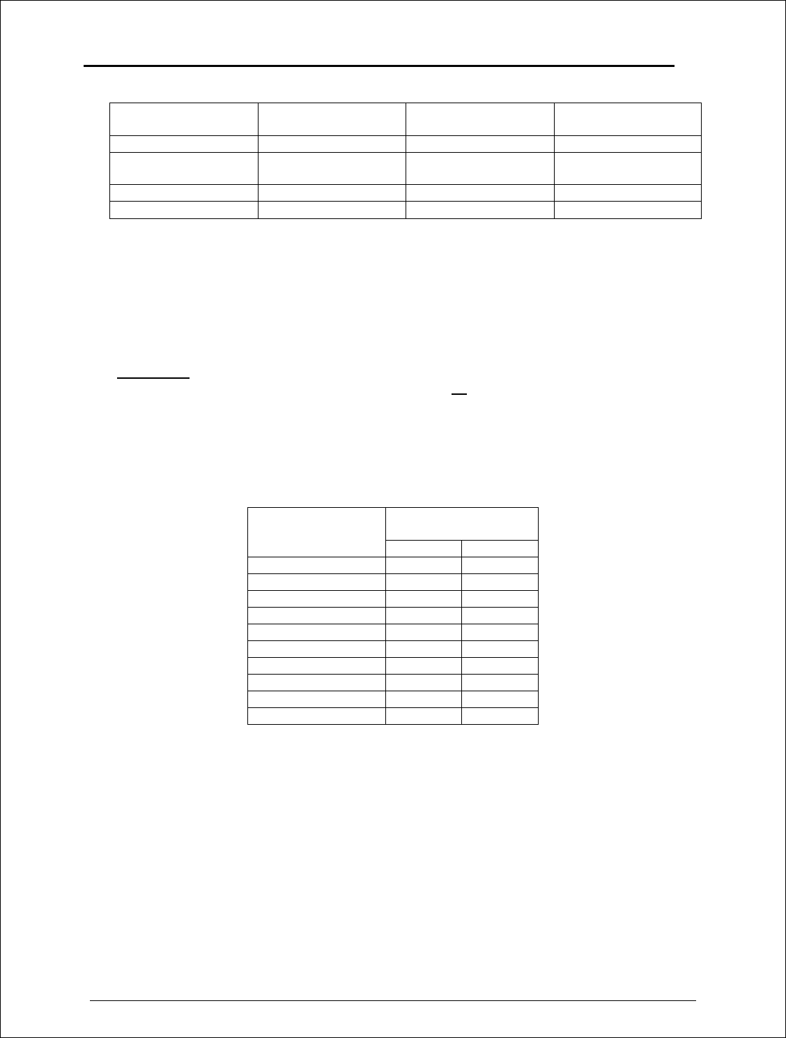
Gain Manufacturer Manufacturer Model
Number FreeWave Model
Number
14 dB, directional Mobile Mark SCR14-2400 EAN2414CR
Adjustable gain, 17
dB max, directional Maxrad MSP24013MB EAN2417CR
5 dB, omnidirectional Maxrad MAXC24505 EAN2405WC
0 dB, omnidirectional MobileMark PSTN3-2400N EAN2400NH
Per FCC regulations maximum permissible EIRP of the communication devices in the 2.4
GHz frequency band is limited differently depending on the communication system
configuration (Point-to-Point or Point-to-Multipoint). Therefore, please be advised that it is
installer responsibility to ensure that the I-Series transceivers installed according to
the guidelines listed below depending on the system configuration. It is also installer’s
responsibility to assure that the emission limits are not exceeded.
WARNING: Any antennas placed outdoors must be properly grounded. Use extreme
caution when installing antennas and follow all instructions included with the
antennas.
The output power of the I-Series radio transceivers can be adjusted by changing “RFXmit
Power” settings on the radio. Table below shows correlation between the “RFXmit Power”
settings and output power of the transceiver.
Transceiver’s
output power
RFXmit Power
settings on the
radio dBm mW
9 27 500
8 26.5 450
7 25.7 375
6 24.5 280
5 22.5 180
4 20 100
3 15.6 40
2 7 5
1 0
0 0
Required “RFXmit Power” settings for each of the antennas provided by FreeWave are given
in the next section of this document. To configure the Power Output Level from the
transceiver follow the steps below:
ü Start “Hyper Terminal” program on the computer connected to the transceiver’s RS232
port (refer to the User Manual for the “Hyper Terminal” setup instructions).
ü Press setup switch on the I-Series transceiver.
ü Choose option number “3” from the Main Menu which appeared on the “Hyper Terminal”
window.

FreeWave Technologies I-Series User Manual Addendum
Installation Manual
V1.0a
3
ü Choose option number “5” from the “Radio Modem Parameters” menu followed by the
settings an appropriate RFXmitPower value, which was defined from the previous
transceiver installation procedure.
6. Repeat the steps above for each I-Series transceiver in the network.
FreeWave Technologies I-Series User Manual Addendum
Installation Manual
V1.0a
4
B. Antenna installation requirements
This section describes what settings can be used on the I-Series transceiver if one of the
provided by FreeWave Technologies antennas is used.
B.1. “Maxrad” MSP24013MB antenna.
The gain of this antenna depends on the beamwidth selected during the installation. Below is
the table showing the dependency between the selected beamwidth of the antenna and its
gain.
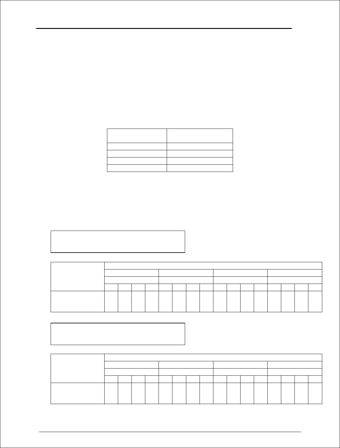
Selected
Beamwidth Gain of the antenna,
dB
45 deg 17
60 deg 16
90 deg 14
120 deg 13
Please refer to the antenna installation manual provided by “Maxrad” for the beamwidht
selection details.
Table B.1.1 and Table B.1.2 below show how the RFXmitPower settings on the radio
correspond to the EIRP of the transceiver-cable-antenna combination for the MSP24013 MB
antenna for the Point-to-Point and Point-to-Multipoint system configurations.
Antenna gain / Beamwidth selected
17 dB / 45 deg 16 dB / 60 deg 14 dB / 90 deg 13 dB/120 deg
Cable loss, dB Cable loss, dB Cable loss, dB Cable loss, dB
1 2 3 4 1 2 3 4 1 2 3 4 1 2 3 4
Maximum
“RFXmit Power”
settings allowed
7 9 9 9 7 9 9 9 9 9 9 9 9 9 9 9
Antenna gain / Beamwidth selected
17 dB / 45 deg 16 dB / 60 deg 14 dB / 90 deg 13 dB/120 deg
Cable loss, dB Cable loss, dB Cable loss, dB Cable loss, dB
1 2 3 4 1 2 3 4 1 2 3 4 1 2 3 4
Maximum
“RFXmit Power”
settings allowed
4 4 4 5 4 4 5 5 5 5 6 7 5 6 7 9
Table B.1.1: Maximum “RFXmit Power” settings allowed for
“Maxrad” MSP24013MB antenna when used in
Point-to-Point system.
Table B.1.2: Maximum “RFXmit Power” settings allowed for
“Maxrad” MSP24013MB antenna when used in
Point-to-Multipoint system.
FreeWave Technologies I-Series User Manual Addendum
Installation Manual
V1.0a
5
B.2. “Mobile Mark” SCR14-2400 antenna.
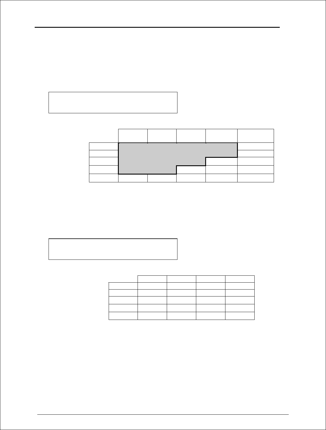
Table B.2.1 below shows how the RFXmitPower settings on the radio correspond to the EIRP
of the transceiver-cable-antenna combination for the SCR14-2400 antenna at different cable
loss values if the communication system is Point-to-Multipoint.
Table B.2.2 below shows how the RFXmitPower settings on the radio correspond to the EIRP
of the transceiver-cable-antenna combination for the SCR14-2400 antenna at different cable
loss values if the communication system is Point-to-Point.
Shaded area indicates combinations where EIRP limitations exceed FCC regulations
and RF Xmit Power must be reduced.
Table B.2.1: EIRP for SCR14-2400 Antenna, Cable loss vs
“RFXmit Power” Setting for Point-to-Multipoint
systems.
Cable Loss
1dB 2dB 3dB 4dB
5 dB
RF Xmit
9
40.00 39.00 38.00 37.00 36.00
Power
8
39.50 38.50 37.50 36.50 35.50
7
38.75 37.75 36.75 35.75 34.75
6
37.50 36.50 35.50 34.50 33.50
5
35.50 34.50 33.50 32.50 31.50
Table B.2.2: EIRP for SCR14-2400 Antenna, Cable loss vs
“RFXmit Power” Setting for Point-to-Point
systems.
Cable Loss
1dB 2dB 3dB 4dB
RF Xmit
9
40.00 39.00 38.00 37.00
Power
8
39.50 38.50 37.50 36.50
7
38.75 37.75 36.75 35.75
6
37.50 36.50 35.50 34.50
5
35.50 34.50 33.50 32.50

FreeWave Technologies I-Series User Manual Addendum
Installation Manual
V1.0a
6
B.3. “Maxrad” MAXC24505 antenna.
Table B.3.1 below is similar to the Tables B.2.1 and B.2.2, but for the MAXC24505 antenna
to be used in either Point-to-Point or Point-to-Multipoint systems.
B.4. “Mobile Mark” PSTN3-2400N antenna.
Table B.4.1 below shows the EIRP if the PSTN3-2400N antenna is used in either Point-to-
Point or Point-to-Multipoint systems.
Table B.3.1: EIRP for MAXC24505 Antenna, Cable loss vs
RF Xmit Power Setting for Point-to-Point and
Point-to-Multipoint systems.
Cable Loss
1dB 2dB 3dB 4dB
RF Xmit
9
31.00 30.00 29.00 28.00
Power
8
30.50 29.50 28.50 27.50
7
29.75 28.75 27.75 26.75
6
28.50 27.50 26.50 25.50
5
26.50 25.50 24.50 23.50
Table B.4.1: EIRP for PSTN3-2400N Antenna, Cable loss
vs RF Xmit Power Setting for Point-to-Point and
Point-to-Multipoint systems.
Cable Loss
1dB 2dB 3dB 4dB
RF Xmit
9
26.00 25.00 24.00 23.00
Power
8
25.50 24.50 23.50 22.50
7
24.75 23.75 22.75 21.75
6
23.50 22.50 21.50 20.50
5
21.50 20.50 19.50 18.50

FreeWave Technologies I-Series User Manual Addendum
Installation Manual
V1.0a
7
C. Transceiver Location
Placement of your I-Series FreeWave unit is likely to have a significant impact on its
performance. In general the rule of thumb with FreeWave is that the higher the placement of the
antenna the better the communication link - height is everything! In practice you should also
place the transceiver away from computers, telephones, answering machines, and other similar
equipment. To improve the data link, FreeWave Technologies offers directional and
omnidirectional antennas with cable lengths ranging from 3 to 200 feet.
When using an external antenna, placement of that antenna is critical to a solid data link. Other
antennas in close proximity are a potential source of interference; use the Radio Statistics to help
identify potential problems. It is also possible that slight adjustments in antenna placement (as
little as 2 feet) will solve noise problems. In extreme cases, such as when the transceiver is
located close to Pager or Cellular Telephone transmission towers, FreeWave offers a band pass
filter to reduce the out of band noise.
The I-Series does not provide protection against water or environmental hazards, and will fade
when placed in direct sunlight. For outdoor applications I-Series may not be used. Please,
contact FreeWave Technologies for more information in this respect.
FreeWave Technologies I-Series User Manual Addendum
Installation Manual
V1.0a
8
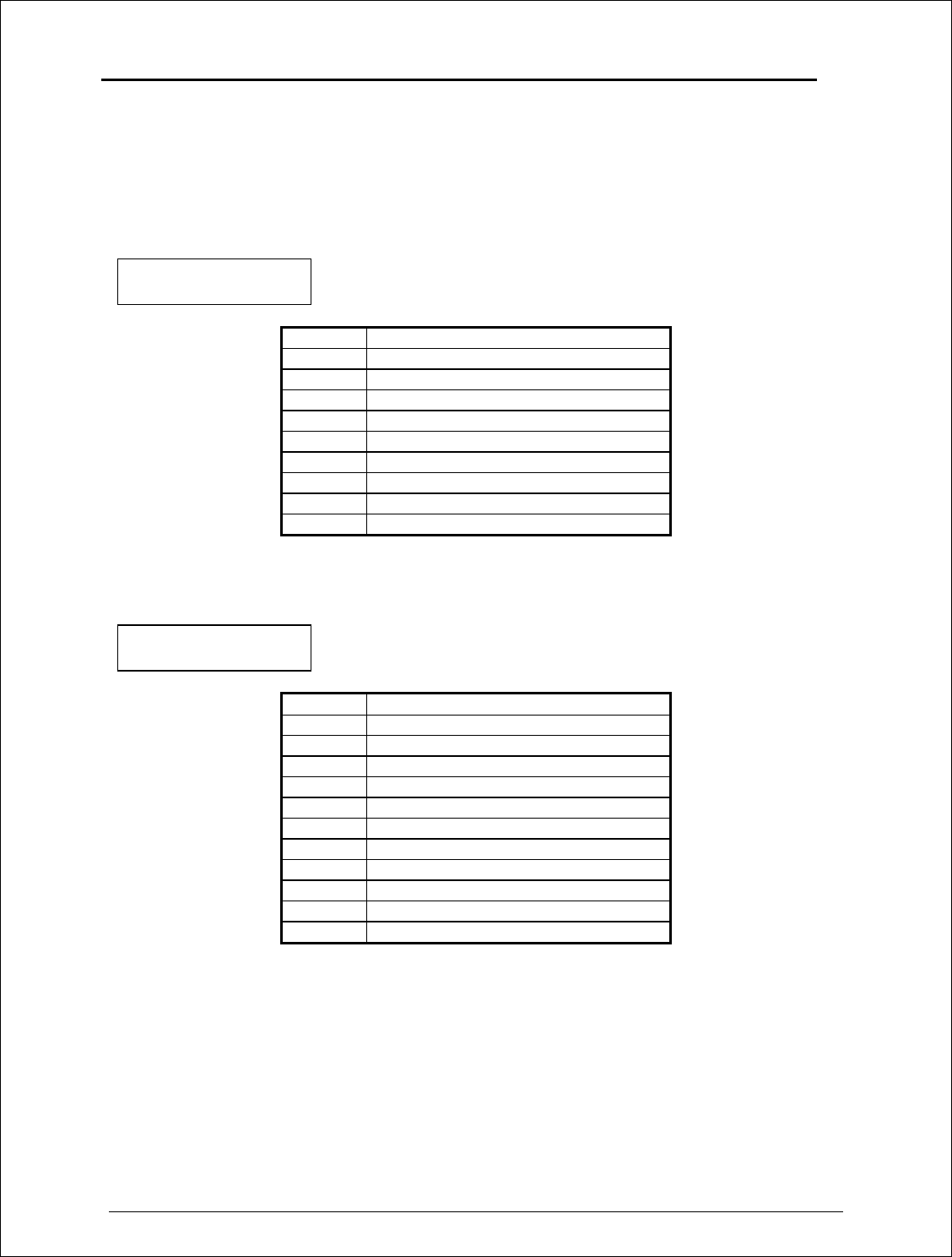
D. Pin Assignments
The I-Series transceiver uses standard RS232 polarity and voltage levels for all of the RS232
signal lines (DTR, Transmit Data, Receive Data, Carrier Detect, RTS, and Clear to Send).
Table D.1: I-800 Series
Pinout
Pin Assignment
1 Carrier Detect (CD)
2 Transmit Data
3 Receive Data
4 Data Terminal Ready (DTR)
5 Ground
6 Data Set Ready (DSR)
7 Ready To Send (RTS)
8 Clear To Send (CTS)
9 Ground
Table D.2: I-900 Series
Pinout
Pin Assignment
1 Carrier Detect (CD)
2 Transmit Data
3 Receive Data
4 Data Terminal Ready (DTR)
5 Ground
6 Data Set Ready (DSR)
7 Ready To Send (RTS)
8 Clear To Send (CTS)
9 Power Ground
10 B+
11 Shield Ground

FreeWave Technologies I-Series User Manual Addendum
Installation Manual
V1.0a
9
E. Power Connection
The I-Series transceiver can be operated from any well-filtered 9.5-30 VDC power source. The
power source should be capable of providing at least 0.6 amperes of continuous current.
Transceiver is designed to operate in negative ground systems only