FreeWave Technologies 821191151819 LRS-445 User Manual My
FreeWave Technologies Inc. LRS-445 My
UserManual.wiki
>
FreeWave Technologies
>
821191151819 User Manual
>
User Manual
Contents
1.
User Manuals
2.
User Manual
User Manual
Navigation menu
Upload a User Manual
Namespaces
Wiki Guide
HTML
PDF
Info
Views
User Manual
Discussion / Help
Navigation

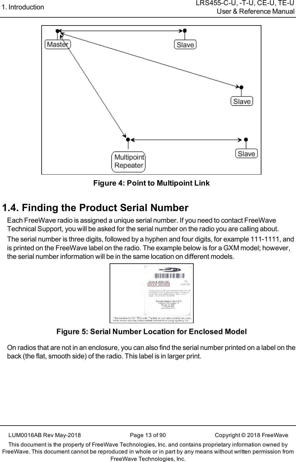
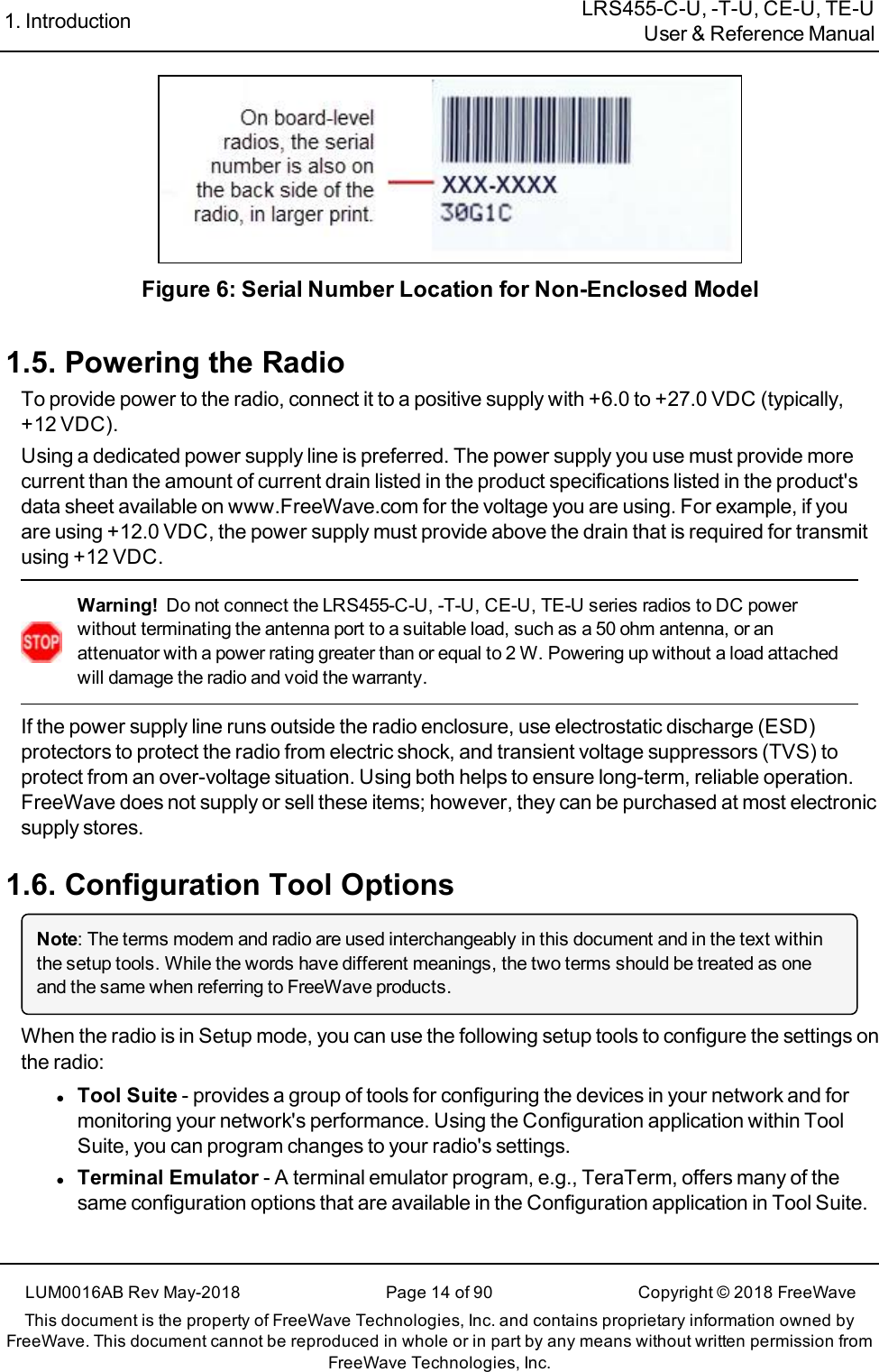
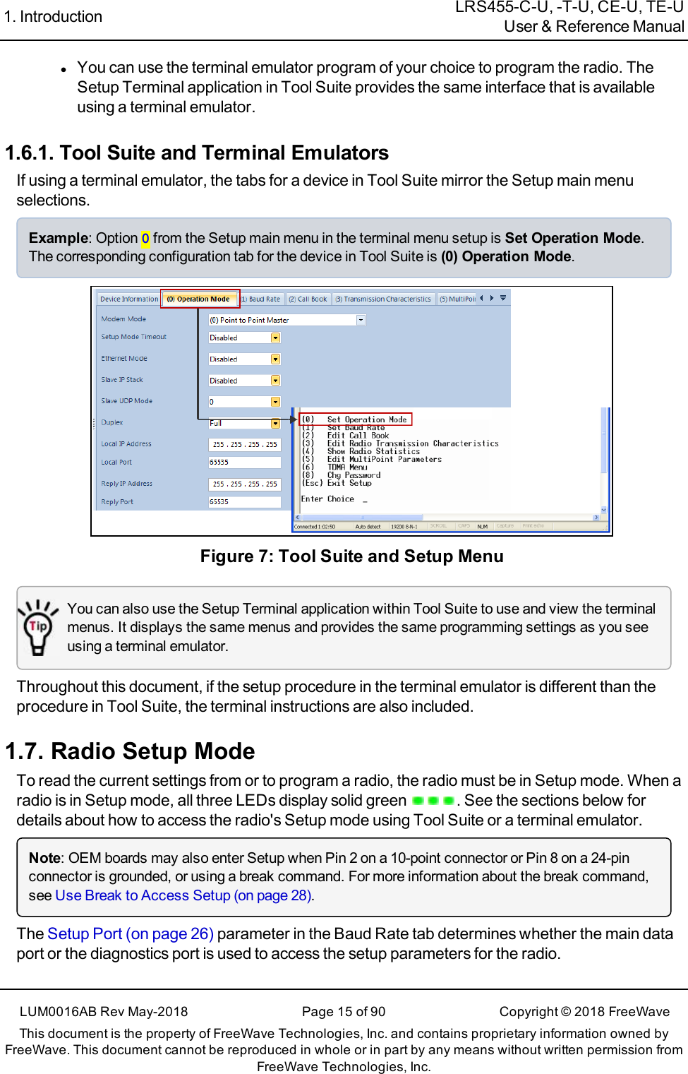
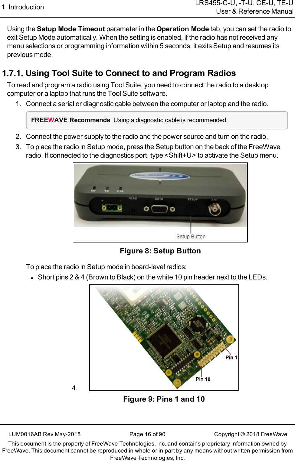
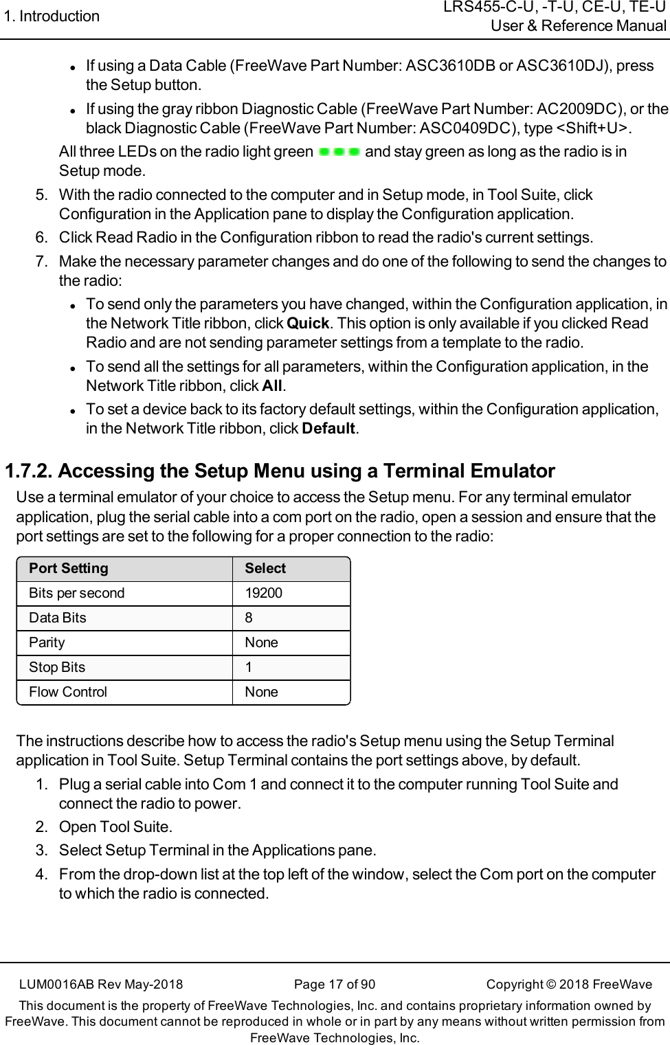
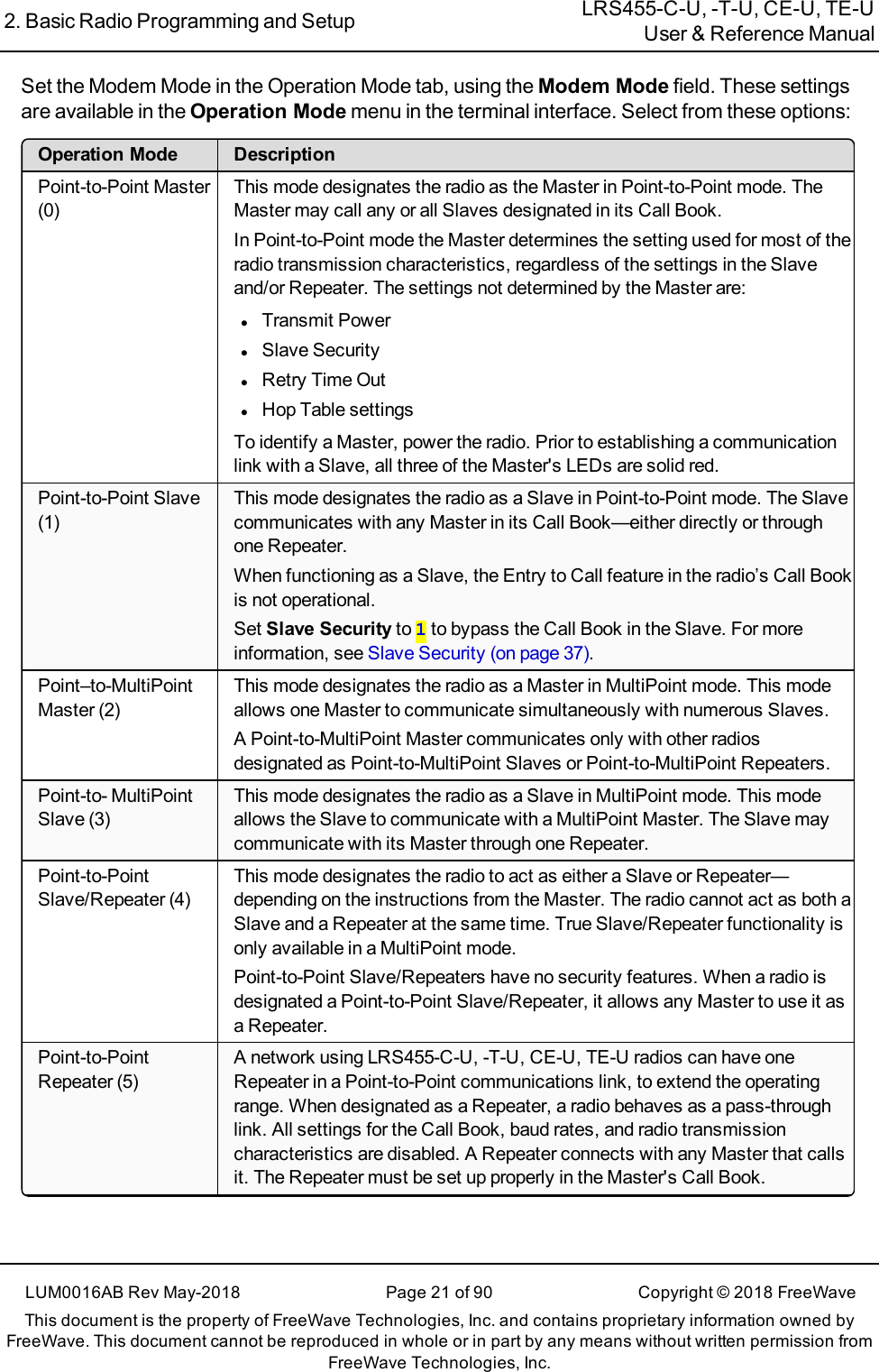
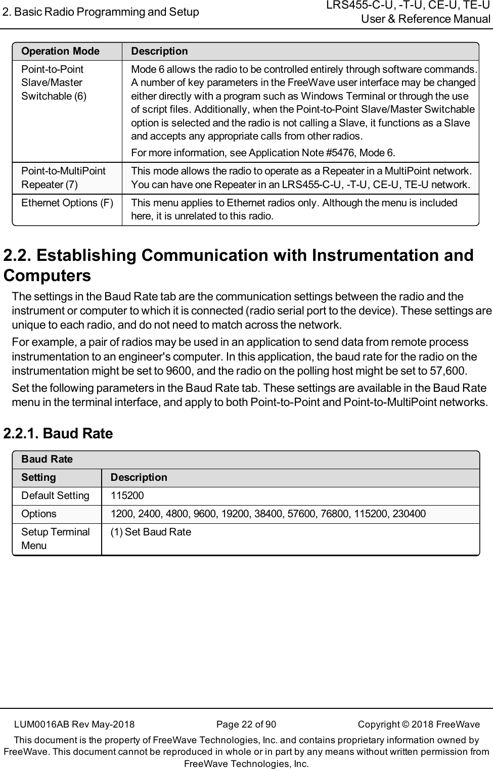
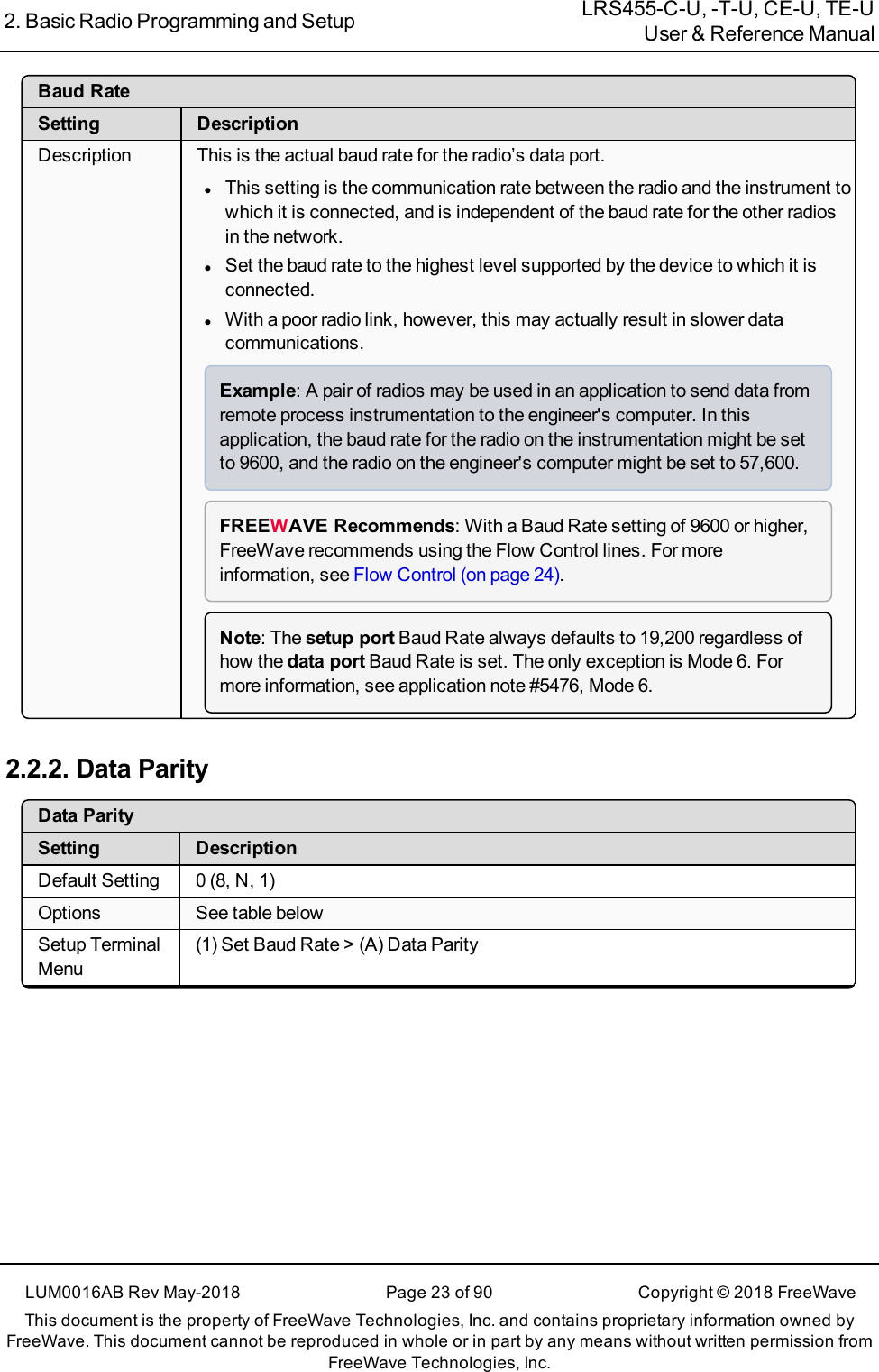
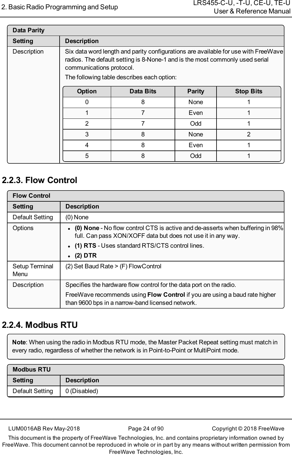
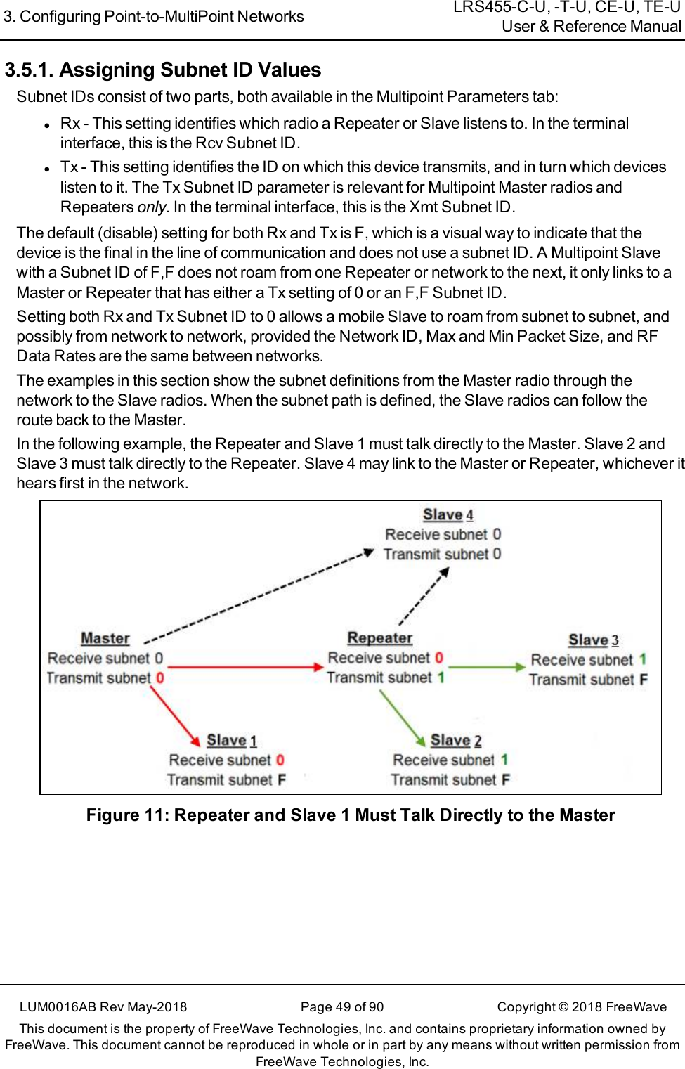
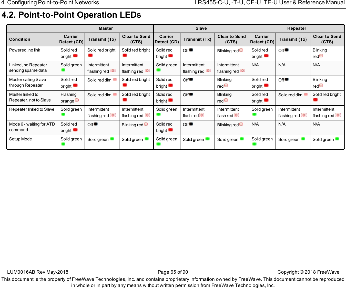
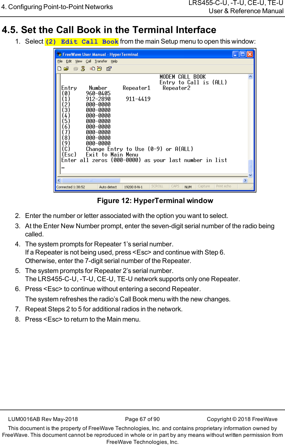
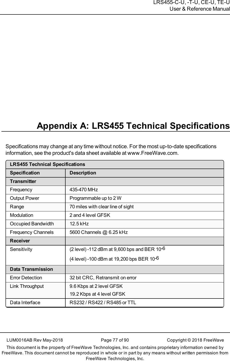
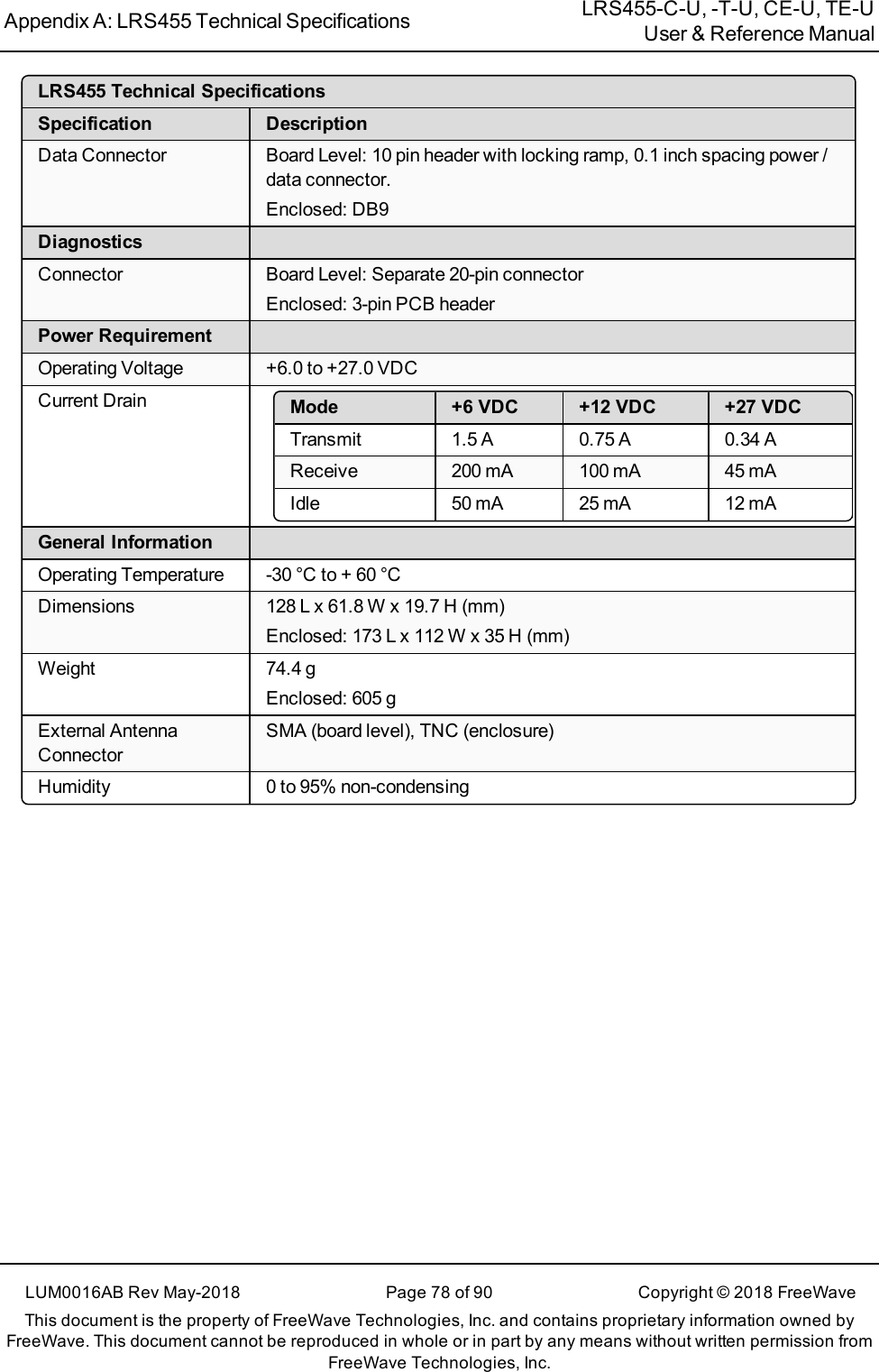
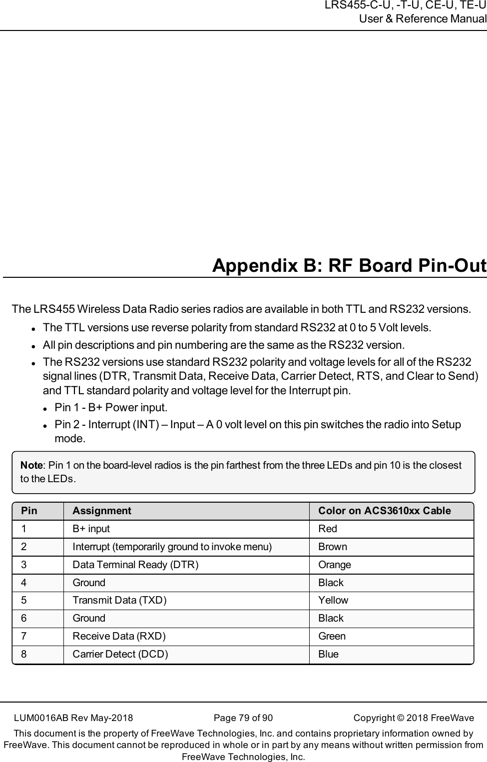
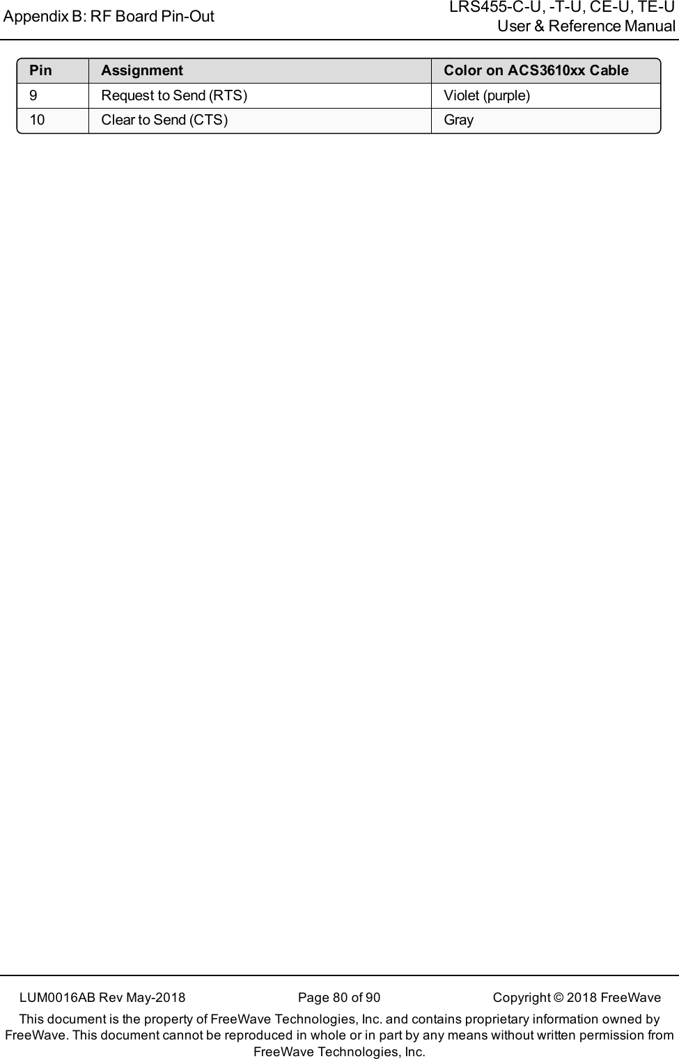
![Preface LRS455-C-U, -T-U, CE-U, TE-UUser & Reference ManualLUM0016AB Rev May-2018 Page 8 of 90 Copyright © 2018FreeWaveThis document is the property of FreeWave Technologies, Inc. and contains proprietary information owned byFreeWave. This document cannot be reproduced in whole or in part by any means without written permission fromFreeWave Technologies, Inc.lParameter setting text appears as: [Page=radioSettings]lFile names appear as: configuration.cfg.lFile paths appear as: C:\Program Files (x86)\FreeWave Technologies.lUser-entered text appears as: xxxxxxxxx.l3rd-party names appear as: Notepad®.Caution: Indicates a situation that may cause damage to personnel, the radio, data, ornetwork.Example: Provides example information of the related text.FREEWAVE Recommends: Identifies FreeWave recommendation information.Important!: Provides crucial information relevant to the text or procedure.Note: Emphasis of specific information relevant to the text or procedure.Provides time saving or informative suggestions about using the product.Warning! Indicates a situation that will cause damage to personnel, the radio, data, ornetwork.Parameter Preference TableThe Parameter Preference table describes the parameter, its options, and usage.<Parameter Name>Setting DescriptionDefault Setting The factory default setting for the parameter.Options The options the parameter can be set to.Setup TerminalMenuThe menu path and field name to access the parameter using the terminal menusavailable through the serial port.Description A description of what the parameter is and how it applies to the radio in thenetwork.](https://usermanual.wiki/FreeWave-Technologies/821191151819.User-Manual/User-Guide-3867895-Page-8.png)