FreeWave Technologies ARN2110AT FGRM User Manual FreeWave Technologies Inc
FreeWave Technologies Inc. FGRM FreeWave Technologies Inc
User Manual

FreeWave Technologies
October 22, 2013
900 MHz Spread Spectrum Installation Manual
V5.3
LIG0003AC Rev D 1 of 11
FreeWave Technologies, Inc.
900 MHz Wireless Modem
Installation Guide
This installation guide covers all models of the FreeWave Technologies 900 MHz spread
spectrum transceiver sold under FCC ID KNY-6231812519 and KNYARN2110AT.
All transceiver models sold under FCC ID KNY-6231812519 and KNYARN2110AT
must be installed professionally. These transceivers are only approved for use
when installed in devices produced by FreeWave Technologies or third party
OEMs approved by FreeWave Technologies. The antenna(s) to be used must be
installed to provide a separation distance of at least 23 cm from all persons and
must not be co-located or operating in conjunction with any other antenna or
transmitter. This transceiver must be installed in a NEMA enclosure.

FreeWave Technologies
October 22, 2013
900 MHz Spread Spectrum Installation Manual
V5.3
LIG0003AC Rev D 2 of 11
FCC Notification
This device complies with part 15 of the FCC rules. Operation is subject to
the following two conditions: 1) This device may not cause harmful
interference and 2) this device must accept any interference received,
including interference that may cause undesired operation.
This device must be operated as supplied by FreeWave Technologies, Inc.
Any changes or modifications made to the device without the express written
approval of FreeWave Technologies may void the user's authority to operate
the device.
CAUTION: This device has a maximum transmitted output power of 955 mW. It
is required that the transmit antenna be kept at least 23 cm away
from nearby persons to satisfy FCC RF exposure requirements.
Note: This equipment has been tested and found to comply with the limits for a Class B digital
device, pursuant to part 15 of the FCC Rules. These limits are designed to provide reasonable
protection against harmful interference in a residential installation. This equipment generates,
uses and can radiate radio frequency energy and, if not installed and used in accordance with the
instructions, may cause harmful interference to radio communications. However, there is no
guarantee that interference will not occur in a particular installation. If this equipment does cause
harmful interference to radio or television reception, which can be determined by turning the
equipment off and on, the user is encouraged to try to correct the interference by one or more of
the following measures:
♦ Reorient or relocate the receiving antenna.
♦ Increase the separation between the equipment and receiver.
♦ Connect the equipment into an outlet on a circuit different from that to which the receiver is
connected.
♦ Consult the dealer or an experienced radio/TV technician for help.
Note: Whenever any FreeWave Technologies module is placed inside an enclosure a label
must be placed on the outside of that enclosure which includes the module's FCC ID.
UL Notification
Model DGRO9RFS:
GENERAL:
The device covered by this Report is a wireless data transceiver. It must be installed in a
suitable enclosure.
FreeWave Technologies
October 22, 2013
900 MHz Spread Spectrum Installation Manual
V5.3
LIG0003AC Rev D 3 of 11
RATINGS:
The device is supplied by a NEC Class 2 Power Supply supplying:
6 V dc to 14 V dc at 600 mA @ 57.6 KBAUD max.
6 V dc to 18 V dc at 600 mA @ 19.2 KBAUD max.
Conditions of Acceptability – When installed in the end use equipment, the following
considerations are to be examined:
1. The transceivers shall be mounted within an enclosure which is suitable for the intended
application. The enclosure shall also have provisions for Division 2 wiring methods as
specified in the National Electrical Code or Canadian Electrical Code, as applicable.
2. The transceivers must be used within their Recognized “Ratings” at an acceptable
transmission rate. “Increasing the baud rate may impair the safety characteristics for
Class I, Division 2 Hazardous Locations.”
3. Installations and use should be in accordance with the National Electrical Code or
Canadian Electrical Code, as applicable.
4. The connectors shall not be connected or disconnected while circuit is alive unless area
is known to be nonhazardous.
5. The end product shall be marked with a warning for the end user indicating that changes
to the baud rate may impair the safety characteristics for Class I, Division 2 Hazardous
Locations.
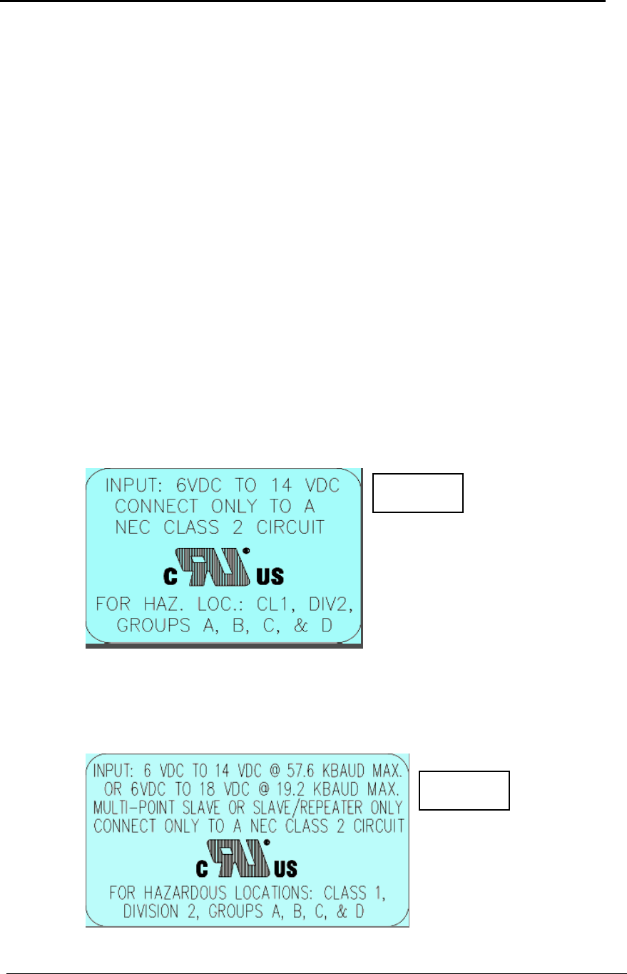
Input voltages for Model# DGRO9RFS are determined by the label on the bottom of the board. If
the board has Label A shown below the input voltage is 6 to 14 volts DC.
If the board has Label B shown below the input voltage is 6 to 14 volts DC at a
maximum baud rate of 57.6 KBaud or 6 to 18 volts DC at a maximum baud rate of
19.2 KBaud, operation mode of multipoint slave or multipoint slave/repeater only.
Class 1 Div 2
Label A
Class 1 Div 2
Label B

FreeWave Technologies
October 22, 2013
900 MHz Spread Spectrum Installation Manual
V5.3
LIG0003AC Rev D 4 of 11
Models FGR2-IOS-T-U*, FGR2-IOS-TE-U*, FGR2-IOS-C-U, FGR2-IOS-CE-U,
FGR2-TE-U*, FGR2-CE-U, FGR2-RE-U*, FGR2-C-U, FGR2-T-U*, FGR2-R-U*
FGRM-C2, and FGRM-C3.
* Model not currently in production
GENERAL:
The devices covered by this Report are wireless data transceivers. These devices are
intended to be installed in a suitable enclosure.
RATINGS:
The devices are powered by a NEC Class 2 Power Supply:
Operating voltage range 6 V dc to 30 V dc at 500 mA(Avg)
Maximum operating ambient temperature is 40° C.
Conditions of Acceptability – When installed in the end use equipment, the following
considerations are to be examined:
1. The transceivers shall be mounted within an enclosure which is suitable for the intended
application. The enclosure shall also have provisions for Division 2 wiring methods as
specified in the National Electrical Code or Canadian Electrical Code, as applicable.
2. The transceivers must be used within their Recognized “Ratings” and conditions of
acceptability as referenced in Users Manual.
3. Installations and use should be in accordance with the National Electrical Code or
Canadian Electrical Code, as applicable.
4. The connectors shall not be connected or disconnected while circuit is alive unless area
is known to be non-hazardous.
5. Must be connected to a Class 2 source.
6. The diagnostics port and cable do not have a latching connector and cannot be used in a
hazardous location.
7. The End-Use Device must be provided with Markings and Installation Instructions in
accordance with the End-Use standards. At a minimum the following must be included in
the Installation Instructions:
a. “This equipment is suitable for use in Class I, Division 2, Groups A, B, C, and D
or non-hazardous locations only.”
b. “WARNING: DO NOT REMOVE OR INSERT THE DIAGNOSTICS CABLE
WHILE CIRCUIT IS LIVE UNLESS THE AREA IS KNOWN TO BE FREE OF
IGNITION CONCENTRATIONS OF FLAMMABLE GASES OR VAPORS.”
Models FGRSR-CSU, RSU, and TSU
GENERAL:
FGRSR-CSU, RSU, and TSU are suitable for use in a 40°C ambient.
The devices covered by this Report are low powered radios. They must be installed in a
suitable enclosure.
RATINGS:
The devices are supplied by a NEC Class 2 Power Supply as follows:
FGRSR-CSU, -RSU, and -TSU:
6 V dc to 20 V dc at 500 mA (Avg) @ 115.2K bd max.

FreeWave Technologies
October 22, 2013
900 MHz Spread Spectrum Installation Manual
V5.3
LIG0003AC Rev D 5 of 11
Conditions of Acceptability – When installed in the end use equipment, the following
considerations are to be examined:
1. The data reporting radio shall be mounted within an enclosure which is suitable for the
intended application. The enclosure shall also have provisions for Division 2 wiring methods as
specified in the National Electrical Code or Canadian Electrical Code, as applicable.
2. The data reporting radio must be used within their Recognized ratings and transmission
rate.
3. Installations and use should be in accordance with the National Electrical Code or
Canadian Electrical Code, as applicable.
4. The connectors shall not be connected or disconnected while circuit is alive unless area is
known to be nonhazardous. Connector J2 is only used for programming the device; it has not
been evaluated as a non-incendive circuit.
5. The end product shall be marked with a warning for the end user indicating that changes
to the baud rate may impair the safety characteristics for Class I, Division 2 Hazardous Locations.
6. The diagnostics port and cable do not have a latching connector and cannot be used in a
hazardous location.
FGRIO-S
GENERAL:
FRGIO-S is suitable for use in a 40°C ambient.
The device covered by this Report is a wireless radio transceiver that accepts up to 2
analog input and 2 digital output signals from a sensor. They must be installed in a
suitable enclosure.
RATINGS:
The devices are supplied by a NEC Class 2 Power Supply as follows:
FGRIO-S: 6 V dc to 20 V dc @ 115.2K bd max.
Conditions of Acceptability – When installed in the end use equipment, the following
considerations are to be examined:
1. The data reporting radio shall be mounted within an enclosure which is suitable for the
intended application. The enclosure shall also have provisions for Division 2 wiring
methods as specified in the National Electrical Code or Canadian Electrical Code, as
applicable.
2. The data reporting radio must be used within their Recognized ratings and transmission
rate.
3. Installations and use should be in accordance with the National Electrical Code or
Canadian Electrical Code, as applicable.
4. The connectors shall not be connected or disconnected while circuit is alive unless area
is known to be nonhazardous. Connector J2 is only used for programming the device; it
has not been evaluated as a non-incendive circuit.
5. The end product shall be marked with a warning for the end user indicating that changes
to the baud rate may impair the safety characteristics for Class I, Division 2 Hazardous
Locations.
6. The diagnostics port and cable do not have a latching connector and cannot be used in a
hazardous location.

FreeWave Technologies
October 22, 2013
900 MHz Spread Spectrum Installation Manual
V5.3
LIG0003AC Rev D 6 of 11
FGRIO-M
GENERAL:
FGRIO-M is suitable for use in a 40°C ambient.
Conditions of Acceptability – When installed in the end use equipment, the following
considerations are to be examined:
1. The data reporting radio shall be mounted within an enclosure which is suitable for the
intended application. The enclosure shall also have provisions for Division 2 wiring
methods as specified in the National Electrical Code or Canadian Electrical Code, as
applicable.
2. The data reporting radio must be used within their Recognized ratings and transmission
rate.
3. Installations and use should be in accordance with the National Electrical Code or
Canadian Electrical Code, as applicable.
4. The connectors shall not be connected or disconnected while circuit is alive unless area
is known to be nonhazardous. Connector J2 is only used for programming the device; it
has not been evaluated as a non-incendive circuit.
5. The end product shall be marked with a warning for the end user indicating that changes
to the baud rate may impair the safety characteristics for Class I, Division 2 Hazardous
Locations.
6. Must be connected to a Class 2 source.
Models FGRO9CSU, FGRM-501X018D, FGRM-501X015, FGRM-511X015,
FGRM-506X015, and FGRM-516X015
GENERAL:
The devices covered by this Report are wireless data transceivers. They must be
installed in a suitable enclosure.
RATINGS:
The devices are supplied by a NEC Class 2 Power Supply as follows:
FGRO9CSU, FGRM-501X018D, FGRM-501X015, FGRM-511X015:
6 V dc to 30 V dc at 500 mA (Avg) @ 115.2K bd max.
FGRM-506X015, FGRM-516X015:
5.5 V dc to 7.5 V dc at 370 mA (Avg) @ 115.2K bd max.
Conditions of Acceptability – When installed in the end use equipment, the following
considerations are to be examined:
1. The transceivers shall be mounted within an enclosure which is suitable for the intended
application. The enclosure shall also have provisions for Division 2 wiring methods as
specified in the National Electrical Code or Canadian Electrical Code, as applicable.
2. The transceivers must be used within their Recognized ratings and transmission rate.
3. Installations and use should be in accordance with the National Electrical Code or
Canadian Electrical Code, as applicable.
FreeWave Technologies
October 22, 2013
900 MHz Spread Spectrum Installation Manual
V5.3
LIG0003AC Rev D 7 of 11
4. The connectors shall not be connected or disconnected while circuit is alive unless area
is known to be nonhazardous. Connector J2 is only used for programming the device; it
has not been evaluated as a non-incendive circuit.
5. The end product shall be marked with a warning for the end user indicating that changes
to the baud rate may impair the safety characteristics for Class I, Division 2 Hazardous
Locations.
6. Must be connected to a Class 2 source.
7. The diagnostics port and cable do not have a latching connector and cannot be used in a
hazardous location.
A. Transceiver installation steps
To install the DGR, FGR, and FGR2 series transceivers, follow the basic steps given below.
1. Mount the transceiver to the flat, stable surface using mounting holes in the corners of the
transceiver. FreeWave recommends a minimum stand-off height of ¼”. The following
mounting bracket solutions are available from FreeWave Technologies: Model #ONTWK-001
and Model #PMB-ENCL.
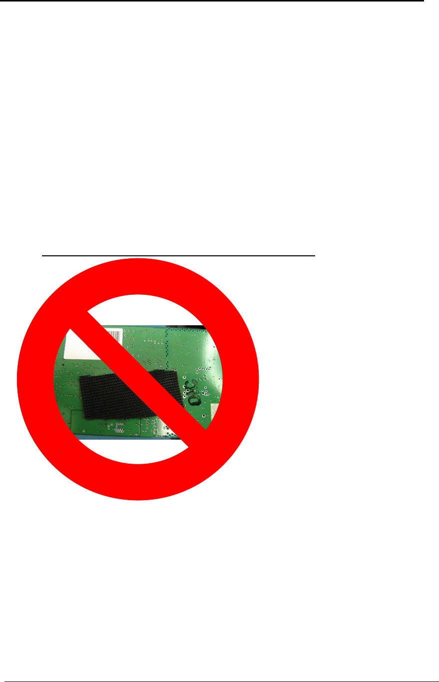
DO NOT USE VELCRO® TO MOUNT THE RADIO
• Attaching and detaching Velcro® pieces creates an ESD (Electro-static Discharge)
hazard. ESD can damage the radio’s circuitry. It also has the potential to damage
other electronic devices close by.
• Mounting a radio to a metal surface with Velcro® does not provide enough distance
between the surfaces, and can result in an electrical short across the radio
Velcro® is the registered trademark of Velcro Industries B.V.
2. Install the antenna and connect the antenna feedline to the transceiver. If you are installing a
directional antenna, preset the antenna’s direction appropriately. The antenna must be
FreeWave Technologies
October 22, 2013
900 MHz Spread Spectrum Installation Manual
V5.3
LIG0003AC Rev D 8 of 11
professionally installed on fixed-mounted permanent outdoor structures for satisfying RF
exposure requirements.
3. Connect a computer to the transceiver’s RS232 port (please refer to the part C of this
addendum for more information about the transceiver’s pin assignment). This computer will
be used to set the radio’s configurations.
4. Install the power for the radio.
5. Set the radio configuration according to the system topology and data terminal equipment
requirements. Default transceiver settings allow user to do a quick installation without major
changes in transceiver’s configuration. But there is one parameter that must be considered
for a new installation – transceiver’s power output settings.
Transceiver output power level must be set according to the tables given below to satisfy
FCC maximum EIRP requirement. Per FCC regulations, any antenna used with FreeWave
transceivers must either be one of the approved antennas shown below or an antenna
approved by FreeWave Technologies with comparable performance parameters. FreeWave
Technologies offers a variety of omnidirectional and directional external antennas, with both
bracket and magnetic mounts. The complete list of antennas available from FreeWave
Technologies including antenna gains, antenna manufacturer’s information and antenna’s
characteristics is shown below:
The following antennas are approved for use with FreeWave transceivers covered in this
guide, except for the FGRM models:
900 MHz Directional Antennas
Gain
Manufacturer
Manufacturer
Model Number
FreeWave
Model Number
8.85 dBd/11 dBi
Larsen
YA5-900-W
EAN0900YA
10 dBd/12.15 dbI
Bluewave
BMY890K5502N4
EAN0900YC
5.85 dBd/8 dBi
Larsen
YA6-900-W
EAN0906YA
6.5 dBd/8.65 dBi
Bluewave
BMY890G5502N4
EAN0906YC
900 MHz Omni-directional Antennas
Gain
Manufacturer
Manufacturer
Model Number
FreeWave
Model Number
-0.15 dBd/2 dBi
Mobile Mark
PSKN3-925S
EAN0900SR
-2.15 dBd/0 dBi
Mobile Mark
PSTG0-915SE
EAN0900SQ
3 dBd/5.15 dBi
Maxrad
MAX-9053
EAN0900WC
2.85 dBd/5 dBi
Antenex
EB8965C
EAN0905WC
8.5 dBd/12.15 dBi
Antenex
FG9026
EAN0906WB
The following antennas are approved for use the FGRM models:
900 MHz Omni-Directional Antennas
Gain
Manufacturer
Manufacturer
Model Number
FreeWave
Model Number
6 dBd/8.15 dBi
Antenex
FG9026
EAN0906WB
FreeWave Technologies
October 22, 2013 900 MHz Spread Spectrum Installation Manual
V5.3
LIG0003AC Rev D 9 of 11
WARNING: Any antennas placed outdoors must be properly grounded. Use extreme
caution when installing antennas and follow all instructions included with the
antennas.
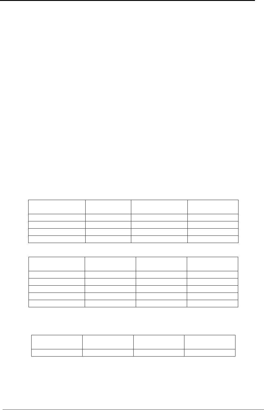
Table 1 below provides the maximum output power settings for FreeWave transceivers at
given antenna gain (12.15 dBi and 8.15 dBi Yagi antennas are given as an example) and
cable loss combinations. Please note that it is the installer’s responsibility to ensure that
the emission limits are not exceeded.
Table 2 below shows how the Transmit Power settings on the radio correspond to the EIRP
of the transceiver-cable-antenna combination for the 12.15 dBi Yagi antenna at different
cable loss values.
Shaded area indicates combinations where EIRP limitations exceed FCC regulations
and RF Xmit Power must be reduced.
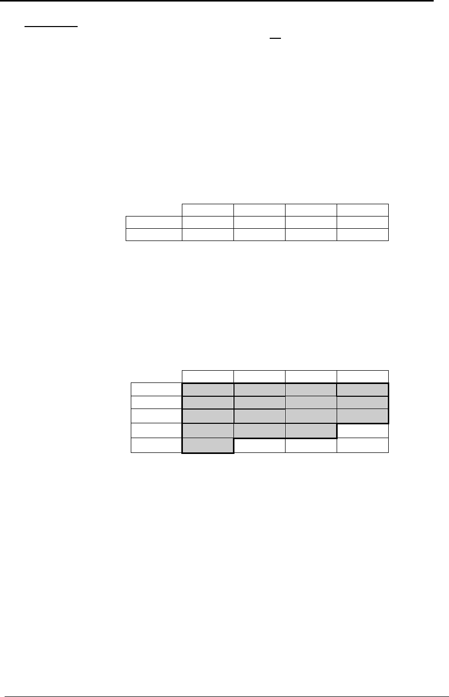
Table 3 below is similar to the Table 2, but shows the information for the 8.15 dB Omni
antenna.
Table 1: Output Power Settings at given Antenna Gain &
Cable Loss combination.
Cable Loss
1dB 2dB 3dB 4dB
Antenna 12.15 dBi 5 6 6 7
Gain 8.15 dBi 8 9 10 10
Table 2: EIRP for 12.15 dBi Yagi Antenna, Cable loss vs.
RF Xmit Power Setting.
Cable Loss
1dB 2dB 3dB 4dB
RF Xmit 10 41.15 40.15 39.15 38.15
Power 9 40.25 39.25 38.25 37.25
8 39.25 38.25 37.25 36.25
7 38.05 37.05 36.05 35.05
6 36.75 35.75 34.75 33.75
Table 3: EIRP for 8.15 dBi Omni Antenna, Cable loss vs.
RF Xmit Power Setting.

FreeWave Technologies
October 22, 2013
900 MHz Spread Spectrum Installation Manual
V5.3
LIG0003AC Rev D 10 of 11
Follow the steps below to configure the Power Output Level:
Start HyperTerminal or any other terminal emulation program on the computer connected
to the transceiver’s RS232 port (refer to the User Manual for the HyperTerminal setup
instructions).
Invoke the setup menu on the transceiver.
Choose option number “3” from the Main Menu which appeared on the “Hyper Terminal”
window.
Choose option number “5” from the “Radio Modem Parameters” menu followed by the
settings an appropriate RFXmitPower value, which was defined from the previous
transceiver installation procedure.
6. Repeat the steps above for each transceiver in the network.
NOTE. Please, be advised that antennas other than listed in this section can potentially be
used with the transceiver provided that:
• these antennas are of a similar type to the listed above;
• antenna gain does not exceed 8.15 dBi for omnidirectional and 12.15 dBi for
directional antennas
• overall system EIRP does not exceed 36 dBm.
WARNING: Any antenna other than listed in this section needs to be approved by
FreeWave Technologies before it is used to assure that the transceiver in combination
with the new antenna meets FCC requirements.
B. Transceiver Location
Placement of the FreeWave transceiver is likely to have a significant impact on its performance.
In general the rule of thumb with FreeWave is that the higher the placement of the antenna the
better the communication link - height is everything! In practice you should also place the
transceiver away from computers, telephones, answering machines, and other similar equipment.
To improve the data link, FreeWave Technologies offers directional and omnidirectional antennas
with cable lengths ranging from 3 to 200 feet.
When using an external antenna, placement of that antenna is critical to a solid data link. Other
antennas in close proximity are a potential source of interference; use the Radio Statistics or
Diagnostics software to help identify potential problems. It is also possible that slight adjustments
Cable Loss
1dB
2dB
3dB
4dB
RF Xmit
10
37.15
36.15
35.14
34.15
Power
9
36.25
35.25
34.25
33.25
8
35.25
34.25
33.25
32.25
7
34.05
33.05
32.05
31.05
6
32.75
31.75
30.75
29.75
FreeWave Technologies
October 22, 2013
900 MHz Spread Spectrum Installation Manual
V5.3
LIG0003AC Rev D 11 of 11
in antenna placement (as little as 2 feet) will solve noise problems. In extreme cases, such as
when the transceiver is located close to Pager or Cellular Telephone transmission towers,
FreeWave offers a band pass filter to reduce the out of band noise.
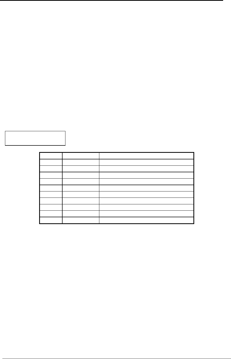
C. Board Level Pin Assignments
The board level transceiver uses standard RS232 polarity and voltage levels for all of the RS232
signal lines (DTR, Transmit Data, Receive Data, Carrier Detect, RTS, and Clear to Send).
Pin 1: B+ Power input.
Pin 2: Interrupt (INT) – Input – A 0 volt level on this pin will switch the radio into setup mode.
Note: Pin 1 on the DGRO9 board level transceiver is the pin farthest from the three
LEDs and pin 10 is closest to the LEDs.
D. Power Connection
The DGR and FGR series transceivers can be operated from any Class 2 power source, input
voltages vary by model. The power source should be capable of providing at least 0.8 amperes
of continuous current. The pin #1 of the 10-pin connector on the transceiver is the positive lead;
pin #4 or pin #6 of this connector should be as a negative lead.
Transceiver is designed to operate in negative ground systems only.
Table 4: Board Level
Transceiver Pinout
Pin
Signal
Assignment
1
Input
B+ input
2
Input
Interrupt (Ground to invoke menu)
3
Input
DTR
4
Ground
5
Output
Transmit Data
6
Ground
7
Input
Receive Data
8
Output
Carrier Detect
9
Input
RTS
10
Output
Clear to Send