FreeWave Technologies ASM1101CR 802.11bgn PCIe Module User Manual My
FreeWave Technologies Inc. 802.11bgn PCIe Module My
Contents
- 1. user manual
- 2. User manual
- 3. User Manual
User Manual

Part Number: LUM0063AA
Revision: 05/05/2014
WavePoint 10e
User Manual

Warranty
FreeWave Technologies, Inc. warrants your FreeWave® Wireless Data Transceiver against defects in materials and
manufacturing for a period of one year from the date of shipment, depending on model number. In the event of a
Product failure due to materials or workmanship, FreeWave will, at its discretion, repair or replace the Product. For
evaluation of Warranty coverage, return the Product to FreeWave upon receiving a Return Material Authorization
(RMA).
FreeWave’s policy for handling WavePoint products returned due to a fault, after complaint is validated by
FreeWave’s Customer Support, is to replace the product with a new or refurbished unit upon receipt of reported
faulty product. This means failure analysis on said product will not be performed and reported to customers. All
failed units will be bagged and tagged so they can be revisited in the event that FreeWave experiences a high
degree of failures or a trend. At which time, FreeWave will perform a root-cause analysis and take the appropriate
corrective actions. Any visual or external damage noted on returned units will be communicated back to customers
and may void the warranty, at which time, a Purchase Order (PO) will be requested from the customer for product
replacement
In no event will FreeWave Technologies, Inc., its suppliers, or its licensors be liable for any damages arising from
the use of or inability to use this Product. This includes business interruption, loss of business information, or other
loss which may arise from the use of this Product. OEM customer’s warranty periods can vary.
Warranty Policy will not apply in the following circumstances:
1. If Product repair, adjustments, or parts replacements are required due to accident, neglect, or undue
physical, electrical, or electromagnetic stress.
2. If Product is used outside of FreeWave specifications as stated in the Product's data sheet.
3. If Product has been modified, repaired, or altered by Customer unless FreeWave specifically authorized
such alterations in each instance in writing. This includes the addition of conformal coating.
Special Rate Replacement Option
A special rate replacement option is offered to non-warranty returns or upgrades. The option to purchase the
replacement unit at this special rate is only valid for that RMA. The special replacement rate option expires if not
exercised within 30 days of final disposition of RMA.
FreeWave Technologies, Inc.
5395 Pearl Parkway, Suite 100
Boulder, CO 80301
303.381.9200
Toll Free: 1.866.923.6168
Printed in the United States of America. Fax: 303.786.9948
Copyright © 2014 by FreeWave Technologies, Inc. All rights reserved. www.freewave.com
Page 2 of 171 LUM0063AA Rev 05/05/2014
This document is the property of FreeWave Technologies, Inc. and contains proprietary information owned by
FreeWave®. This document cannot be reproduced in whole or in part by any means without written permission from
FreeWave Technologies, Inc.

WavePoint 10e
Restricted Rights
Any product names mentioned in this manual may be trademarks or registered trademarks of their respective
companies and are hereby acknowledged.
This manual is for use by purchasers and other authorized users of FreeWave products.
No part of this manual may be reproduced or transmitted in any form or by any means, electronic or mechanical, or
for any purpose without the express written permission of FreeWave Technologies, Inc. FreeWave reserves the
right to make changes to this manual without notice. FreeWave assumes no responsibility or liability for the use of
this manual or the infringement of any copyright or other proprietary right.
FreeWave Technologies, Inc. products may be subject to control by the Export Administration Regulations
(EAR) and/or the International Traffic in Arms Regulations (ITAR). Export, re-export, or transfer of these
products without required authorization from the U.S. Department of Commerce, Bureau of Industry and
Security, or the U.S. Department of State, Directorate of Defense Trade Controls, as applicable, is prohibited.
Any party exporting, re-exporting, or transferring FreeWave products is responsible for obtaining all
necessary U.S. government authorizations required to ensure compliance with these and other applicable
U.S. laws. Consult with your legal counsel for further guidance.
FCC Notifications
This device complies with part 15 of the FCC rules. Operation is subject to the following two conditions: 1) This
device may not cause harmful interference and 2) this device must accept any interference received, including
interference that may cause undesired operation.
The content of this guide covers FreeWave Technologies, Inc. models sold under FCC ID: KNYPRW1001ER,
KNYASM1101CR, KNYPRW1001EC.
All models sold under the FCC ID(s) listed above must be installed professionally and are only approved for use
when installed in devices produced by FreeWave Technologies or third party OEMs with the express written
approval of FreeWave Technologies, Inc. Changes or modifications should not be made to the device.
IC Notifications
This device complies with Industry Canada license-exempt RSS standard(s). Operation is subject to the following
two conditions: (1) this device may not cause interference, and (2) this device must accept any interference,
including interference that may cause undesired operation of the device.
Ce dispositif est conforme aux normes permis-exemptes du Canada RSS d'industrie. L'opération est sujette aux
deux conditions suivantes : (1) ce dispositif peut ne pas causer l'interférence, et (2) ce dispositif doit accepter
n'importe quelle interférence, y compris l'interférence qui peut causer le fonctionnement peu désiré du dispositif.
WavePoint™ Product Safety
Power Supply Cable
The power supply cable is a 2-wire, size 22AWG.
LUM0063AA Rev 05/05/2014 Page 3 of 171
This document is the property of FreeWave Technologies, Inc. and contains proprietary information owned by
FreeWave®. This document cannot be reproduced in whole or in part by any means without written permission from
FreeWave Technologies, Inc.

WavePoint™ Product Safety
Screw Torque
For all connections, use these tightening torque minimum and maximum:
lMinimum: 0.22 Nm.
lMaximum: 0.25 Nm.
WavePoint™ Conditions of Safe Use
lProvision shall be made to prevent the rated voltage from being exceeded by the transient
disturbances of more than 140% of the peak rated voltage.
lThe WavePoint™shall be mounted in an ATEX certified enclosure with a minimum
IP54 ingress protection rating (as defined in EN-60529).
lThe WavePoint™cannot be used in an environment greater than pollution degree 2.
Standards and Editions
lEN 60079-0:2012+A11:2013
lEN 60079-15:2010
lIEC 60079-0, 6th Edition
lIEC 60079-15, 4th Edition
Page 4 of 171 LUM0063AA Rev 05/05/2014
This document is the property of FreeWave Technologies, Inc. and contains proprietary information owned by
FreeWave®. This document cannot be reproduced in whole or in part by any means without written permission from
FreeWave Technologies, Inc.

WavePoint 10e
Table of Contents
WavePoint™ Product Safety 3
Power Supply Cable 3
Screw Torque 4
WavePoint™ Conditions of Safe Use 4
Standards and Editions 4
Preface 15
Chapter 1: Introduction 17
Key Features and Supported Protocols 18
Wireless Operating Modes 18
Available Network Services 18
Device Management 18
Network Security 19
Requirements 19
Installation Settings 19
Equipment and Configuration 20
Accessories 20
Product Variations 21
WavePoint 10e Labels 21
Sample: Configuration Label 21
Sample: Antenna Port Assignment Label 21
WavePoint™ Components 22
Data Connectors 22
RF Connectors 23
Certified Antennas 23
LUM0063AA Rev 05/05/2014 Page 5 of 171
This document is the property of FreeWave Technologies, Inc. and contains proprietary information owned by
FreeWave®. This document cannot be reproduced in whole or in part by any means without written permission from
FreeWave Technologies, Inc.

WavePoint™ Product Safety
Antenna Installation Warning 23
900MHz Antennas 24
2.4GHz Antennas 24
5GHz Antennas 25
Antenna Installation 26
Placement Considerations 26
Transmit Power Settings 27
RF Loss 27
WavePoint™ EIRP Limits 28
RF Considerations for 2.4GHz ISM Band 28
Peak Power Output 28
Point-to-Point Link 29
Guidelines 29
Point-to-Multi-Point Link 29
RF Considerations for 900MHz ISM Band 30
WavePoint™ GUI to Actual RF Power 30
Connect Power 30
Power Supply Cable 31
Screw Torque 31
Network Deployment Scenarios 31
Wired Access 31
Wireless Access 32
Multiple Repeaters 32
Connecting and Logging In 32
Configuration Pages 34
Page 6 of 171 LUM0063AA Rev 05/05/2014
This document is the property of FreeWave Technologies, Inc. and contains proprietary information owned by
FreeWave®. This document cannot be reproduced in whole or in part by any means without written permission from
FreeWave Technologies, Inc.

WavePoint 10e
Searching for Menus 35
Chapter 2: Configuring Basic WavePoint™ Network Features 37
Setting the Device IP Address and Subnet 38
IPv4 Networks - Set the IP Address and Subnet 38
Reserved Subnets 38
Enabling and Configuring DHCP 39
IPv4 Addressing - Enable and Configure DHCP 39
Reserving IP Addresses 41
Reserve IP Addresses in an IPv4 Network 41
Delete a Specific LAN Reserved IP Address 41
Delete all Reserved IP Addresses 42
Using Multiple WANs or a Single WAN 42
Indicate the Number of WANs in Use 42
Configuring the WAN in an IPv4 Network 43
Defining WAN Connections Using Static IP Addresses 43
Defining WAN Connections Using DHCP 44
Defining WAN Connections Using PPPoE 45
Defining WAN Connections Using PPTP 46
Setting the Device Mode 47
Chapter 3: Additional Data Networking Features 49
Defining Physical WAN Port Settings 49
Setting Up Auto Fail-Over in Multi-WAN Environments 50
Balancing Data Flow in Multi-WAN Environments 51
Restricting the Traffic Type for Each WAN Port 52
Configure a Traffic Restriction (Protocol Binding) for a WAN Port 53
LUM0063AA Rev 05/05/2014 Page 7 of 171
This document is the property of FreeWave Technologies, Inc. and contains proprietary information owned by
FreeWave®. This document cannot be reproduced in whole or in part by any means without written permission from
FreeWave Technologies, Inc.

WavePoint™ Product Safety
Enable or Disable a Protocol Binding Configuration 54
Delete a Protocol Binding Configuration 54
Binding an IP Address to a MAC Address 54
Data Routing 55
Defining Static Routing Rules 55
Define a Static IPv4 Route 56
Delete an Existing Static Route 57
Defining Routing Internet Protocol Rules 57
Define RIP in IPv4 Networks 57
Virtual Local Area Networks (VLANs) 58
Enabling VLANs 59
Defining VLANs in the Network 59
Delete an Available VLAN 60
Mapping VLANs to LAN Subnets 60
Associating Port Traffic to a VLAN 62
WaveMesh 64
WaveMesh Methods 64
Example: WaveMesh Routing Diagram 65
WaveMesh using Auto Selection Method 66
WaveMesh using Branch Selection Method 69
WaveMesh using a List Selection Method 72
Chapter 4: Configuring Wireless Access 79
Example: Point-to-Point Configuration 79
Configuring a Point-to-Point Network 80
Point-to-Multipoint Configuration Examples 80
Page 8 of 171 LUM0063AA Rev 05/05/2014
This document is the property of FreeWave Technologies, Inc. and contains proprietary information owned by
FreeWave®. This document cannot be reproduced in whole or in part by any means without written permission from
FreeWave Technologies, Inc.

WavePoint 10e
Example 1: Point-to-Multipoint 80
Setup Procedure 80
Example 2: Point-to-Multipoint 81
Configuring Wireless Communication 82
Defining Advanced Radio Settings 85
Verify the Wireless Connection 88
Enabling Virtual Access Points 89
Change a Virtual Access Point's Settings 90
Wireless Security 91
Authorizing Wireless Access 91
Restricting Access by MAC Address 92
Set the ACL Policy Type 93
Add or Edit MAC Addresses in the ACL List 93
Delete a Device from the List 94
Enabling Rogue Access Point Detection 94
Review Devices that Attempted to Access the Network 94
Defining EAP Authentication and External RADIUS Servers 95
Configure the EAP Authentication 95
Define an External RADIUS Server 96
Scheduling When Wireless Connections are Available 97
Define and Enable a Schedule for a Wireless Connection 97
Disable a Schedule 98
Chapter 5: Security 99
Firewall Overview 99
Firewall Basic Policies 99
LUM0063AA Rev 05/05/2014 Page 9 of 171
This document is the property of FreeWave Technologies, Inc. and contains proprietary information owned by
FreeWave®. This document cannot be reproduced in whole or in part by any means without written permission from
FreeWave Technologies, Inc.

WavePoint™ Product Safety
Default Outbound Policy 99
Set the Outbound Traffic Policy 100
Firewall Rules 100
Creating Firewall Rules for IPv4 100
Delete an IPv4 Firewall Rule 103
Disable an IPv4 Firewall Rule 103
Custom Services 103
Configure Custom Service Settings 104
Delete an Existing Custom Service 104
VPN Passthrough 105
Firewall Schedules 105
Configuring Firewall Schedules 105
Delete a Firewall Schedule 106
Application Rules 107
Configuring Application Rules 107
Delete an Application Rule 108
Application Rules Status 108
VPN Tunnels and IPsec 109
Configuring a VPN Tunnel with IPsec 109
Configuring a Basic VPN Tunnel 109
IPsec Policies 110
Configuring an IPsec VPN Policy 111
Configuring an Auto-policy that uses IKE to Perform Negotiations between Two VPN
Clients 114
Configure Phase 2 Auto Policy Parameters 116
Page 10 of 171 LUM0063AA Rev 05/05/2014
This document is the property of FreeWave Technologies, Inc. and contains proprietary information owned by
FreeWave®. This document cannot be reproduced in whole or in part by any means without written permission from
FreeWave Technologies, Inc.

WavePoint 10e
Configure Phase 2 Manual Policy Parameters 117
Delete an IPsec VPN Policy 118
Edit the Default DHCP Range 119
Chapter 6: Management and Administration 121
Set Up Remote Access to the WAN Port 122
User Access Management 122
Users and Groups 123
Users 123
Groups 123
Factory Defined Users 123
admin 123
guest 123
Adding and Editing User Groups 124
Default User Groups 124
Define and Assign User Group Login Policies 125
Define User Group Browser Policies 126
Define User Group IP Policies 127
Deleting User Groups Policies 128
Delete a Single User Group Policy 128
Delete all User Policies in a List 128
Deleting User Groups 128
Delete a User Group 128
Delete all User Groups 129
Adding and Editing Users 129
Deleting Users 130
LUM0063AA Rev 05/05/2014 Page 11 of 171
This document is the property of FreeWave Technologies, Inc. and contains proprietary information owned by
FreeWave®. This document cannot be reproduced in whole or in part by any means without written permission from
FreeWave Technologies, Inc.

WavePoint™ Product Safety
Software Maintenance 130
Upgrade the WavePoint 10e Software 130
Back Up Configuration Settings 131
Restore Configuration Settings 132
Restoring Factory Default Settings 133
Rebooting 133
System Logging 134
Set Up System Event Logging 134
Logging Packet Traffic 135
Log Packet Traffic in an IPv4 Network 136
Sending Log Messages to Email Addresses 136
Sending Logs to Syslog Servers 138
Simple Network Management Protocol (SNMP) 139
Authentication Certificates 139
Adding Trusted Certificates (CA Certificates) 139
Generating Self Certificate Requests 140
Adding Active Self Certificates 141
Deleting Certificates 142
Delete a Single Certificate 142
Delete all Certificates 142
Setting the Date and Time 143
Use an NTP Server to Set the Date and Time 143
Manually Set the Date and Time 144
System Statistics 144
Chapter 7: Diagnostics and Troubleshooting 147
Page 12 of 171 LUM0063AA Rev 05/05/2014
This document is the property of FreeWave Technologies, Inc. and contains proprietary information owned by
FreeWave®. This document cannot be reproduced in whole or in part by any means without written permission from
FreeWave Technologies, Inc.

WavePoint 10e
General Troubleshooting 147
Internet Connection and Browser Display 147
Cannot Access the Configuration Pages from a Computer on the LAN 147
Verifying the IP address of a Windows® Computer 148
Configuration Changes are not Saving 148
WavePoint 10e cannot Obtain an IP address from the ISP 148
WavePoint 10e can Obtain an IP address but the PC is Unable to Load Internet Pages 149
Date and Time 149
The Date Shown in the Log Files is January 1, 1970 149
The Time is off by One Hour 149
Appendix A: Factory Default Settings 151
Chapter B: Installation Instructions 153
Attach the DIN Rail Bracket 154
Attach the Mounting Flanges 154
Appendix C: WavePoint™ Configurations 155
WP10e-R100-100-100 155
WP10e-S100-100-100 155
WP10e-S200-101-100 155
WP10e-T100-100-100 156
WP10e-T200-101-100 156
Appendix D: Bench Test Verification of WavePoint™ Configuration 157
Required Materials 157
RF Cabled Test Procedure 157
Open Antenna Test Procedure 158
Appendix E: WavePoint 10e Technical Specifications 161
Glossary 165
LUM0063AA Rev 05/05/2014 Page 13 of 171
This document is the property of FreeWave Technologies, Inc. and contains proprietary information owned by
FreeWave®. This document cannot be reproduced in whole or in part by any means without written permission from
FreeWave Technologies, Inc.

WavePoint™ Product Safety
Index 167
Page 14 of 171 LUM0063AA Rev 05/05/2014
This document is the property of FreeWave Technologies, Inc. and contains proprietary information owned by
FreeWave®. This document cannot be reproduced in whole or in part by any means without written permission from
FreeWave Technologies, Inc.

Preface
This document provides information to configure and setup the WavePoint 10e device and
includes:
lAn introduction to the WavePoint 10e device and its key features.
lPhysical components of the device including its ports and LEDs.
lConfiguring a basic WavePoint 10e network.
lSetting up wireless access.
lUsing a WavePoint 10e for local communication or as a Wi-Fi hotspot.
lPerforming general administrative tasks (e.g., setting up users, defining the system time).
lPerforming basic diagnostics, including troubleshooting tips.
The WavePoint 10e has a variety of configurations for installation flexibility.
Note: The information provided in this documentation assumes the user has a general
understanding of networking devices (e.g., routers, bridges, etc.) and Ethernet and
RF communication.
Contacting FreeWave Technical Support
For up-to-date troubleshooting information, check the Support page at www.freewave.com.
LUM0063AARev 05/05/2014 Page 15 of 171
This document is the property of FreeWave Technologies, Inc. and contains proprietary information owned by
FreeWave®. This document cannot be reproduced in whole or in part by any means without written permission from
FreeWave Technologies, Inc.

Preface
FreeWave provides technical support Monday through Friday, 7:30 AM to 5:30 PM Mountain Time
(GMT -7).
lCall toll-free at 1.866.923.6168.
lIn Colorado, call 303.381.9200.
lContact us through e-mail at moreinfo@freewave.com.
Printing this Document
This document is set to print double-sided with a front cover and a back cover. Viewing this
document online with a PDF viewer, may show pages intentionally left blank to accommodate the
double-sided printing.
Documentation Feedback
Send comments or questions about this document's content to techpubs@freewave.com. In the
email, include the title of the document or the document's part number and revision letter (found in
the footer).
Page 16 of 171 LUM0063AA Rev 05/05/2014
This document is the property of FreeWave Technologies, Inc. and contains proprietary information owned by
FreeWave®. This document cannot be reproduced in whole or in part by any means without written permission from
FreeWave Technologies, Inc.
Chapter 1: Introduction
WavePoint 10e is a powerful, end-to-end wireless networking and communications platform. It
comprises a product family of networking devices to solve network infrastructure and
communications needs. The flexible WavePoint 10e platform delivers high-speed broadband data
communications across an entire network and to any environment.
WavePoint 10e provides:
lFlexible installations on communication towers, rooftops, and street light poles with
diverse power and backhaul and antenna options.
lMultiple applications such as voice, Internet access, video surveillance, sensory data, and
SCADA.
This chapter introduces WavePoint 10e and provides details about:
LUM0063AARev 05/05/2014 Page 17 of 171
This document is the property of FreeWave Technologies, Inc. and contains proprietary information owned by
FreeWave®. This document cannot be reproduced in whole or in part by any means without written permission from
FreeWave Technologies, Inc.

Chapter 1: Introduction
lKey Features and Supported Protocols on page 18
lRequirements on page 19
lAccessories on page 20
lProduct Variations on page 21
lCertified Antennas on page 23
Key Features and Supported Protocols
The WavePoint 10e provides an industrial networking solution for a license-exempt market and
includes these features and standard networking technology and protocols.
Wireless Operating Modes
Configurations for the WavePoint 10e include:
lWireless mode: Access Point / Repeater / Client that can operate concurrently in the 900
MHz, 2.4GHz, and 5GHz bands.
lRouter mode: Network Address Translation (NAT) / Router / Bridge
Both the wireless mode and the router mode (called the Device Mode in the
WavePoint™GUI) can be configured.
For information about how WavePoint 10e fits into a network deployment, see Network
Deployment Scenarios on page 31.
Available Network Services
The networking services and protocols WavePoint 10e provides are:
lConfigurable MTU and PMTU discovery
when set up as an access point.
lDHCP MAC filtering and MAC binding.
lDHCP server or client.
lDynamic DNS clients.
lMulti-instance DHCP server on WLAN.
lMultiple LAN subnets.
lPPPoE, PPTP client
lRIPv1 and RIPv2.
lStatic and dynamic IP addressing.
lStatic and dynamic routing.
lTCP, UDP, and ICMP protocols.
lVLAN setup.
lVPN Tunneling and Transport.
Device Management
Each WavePoint 10e is configured and monitored through a web browser interface.
The management options are:
Page 18 of 171 LUM0063AA Rev 05/05/2014
This document is the property of FreeWave Technologies, Inc. and contains proprietary information owned by
FreeWave®. This document cannot be reproduced in whole or in part by any means without written permission from
FreeWave Technologies, Inc.

WavePoint 10e
lPolicy definition for when the WavePoint 10e is on and listening for network traffic.
lRemote access and provisioning.
lLogging services to monitor and track system performance using email logs, alerts, and
external SYSLOG servers.
lNetwork Time Protocol (NTP).
lUnlimited users definition (subject to the network capacity).
lOver the air firmware updates.
Network Security
The security features WavePoint 10e provides to ensure the data passed through the network is
secure are:
lDevice certificates
lHidden, guest, and maintenance SSIDs
lIPsec
lMAC address filtering
lRADIUS for authentication
lRogue AP detection
lSSL and SSH secured management
lWPA, WPA2
Requirements
Important: Use the www.freewave.com/home/WavePointLogin site to download
the latest WavePoint 10e software. Updating the software to the latest version
provides the best experience with WavePoint 10e.
Installation Settings
Attention Network Administrator! Complete the information in this table.
SSID: _____________________________ (8-64 ASCII characters. The SSID field is case sensitive.)
Security Mode:Security Key: (This field is case sensitive.)
IP Address:Subnet Mask:
DHCP Setup Mode:Max Range: (2x the distance of the longest link in Km)
LUM0063AA Rev 05/05/2014 Page 19 of 171
This document is the property of FreeWave Technologies, Inc. and contains proprietary information owned by
FreeWave®. This document cannot be reproduced in whole or in part by any means without written permission from
FreeWave Technologies, Inc.

Chapter 1: Introduction
Equipment and Configuration
The equipment and configurations required prior to the initial WavePoint 10e setup and installation
are:
lA computer or laptop with:
lWindows 7 operating system.
lA web browser to access the web pages for configuration.
lSupported browsers include: Microsoft Internet Explorer 9 and 10, Firefox 27,
Google Chrome, Safari, and Opera.
Note: Configuration pages are NOT optimized for browsers on mobile devices (e.g.,
tablets, smart phones, etc.)
lA device with wireless capability to verify the wireless connection.
lA NEMA-4 rated enclosure (for outdoor installations only).
lA screwdriver for attaching mounting brackets and power connector.
FreeWave Recommends: A Path Study, as applicable, for the network site.
Accessories
The items shipped in the box are:
lThe WavePoint 10e device.
lThe WavePoint 10e Quick Start Guide.
lA CAT 5e Ethernet cable.
lAn AC power adapter.
These options are available and, if ordered, are included in the shipping box:
lAn RJ-45-to-DB9 serial cable.
lA mounting kit.
Note: Mounting kits must be purchased separately.
FreeWave Part Number Description
POH0031AA DIN Rail Mounting Kit
POH0030AA Wall Mount Bracket Kit (flange)
Page 20 of 171 LUM0063AA Rev 05/05/2014
This document is the property of FreeWave Technologies, Inc. and contains proprietary information owned by
FreeWave®. This document cannot be reproduced in whole or in part by any means without written permission from
FreeWave Technologies, Inc.
WavePoint 10e
Contact a FreeWave reseller or FreeWave Technical Support if the package is missing parts or any
parts were damaged during shipping.
Note: Antennas are shipped separately.
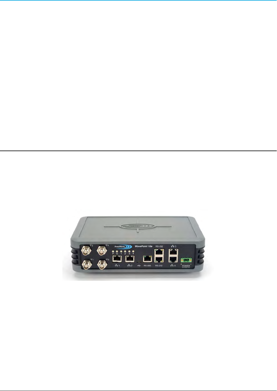
Product Variations
WavePoint™has a variety of configurations offering multiple feature sets. This manual describes
these features and indicates the features that are only available on certain models.
To identify the variation and model number of the WavePoint 10e, see the product label on the back
panel.
Note: For a list of features included in each model, see the WavePoint™ Configurations
on page 155.
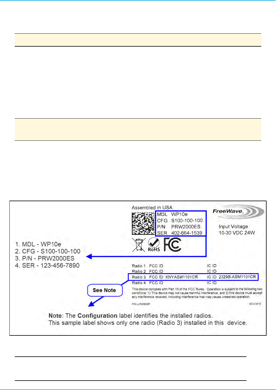
WavePoint 10e Labels
The labels on the back of the WavePoint 10e contain information about the device's port
assignments and Configuration (CFG).
Sample: Configuration Label
Sample: Antenna Port Assignment Label
Important: The information on the Antenna Port Assignment label is critical for
correct antenna connections and operation of the WavePoint™device.
LUM0063AA Rev 05/05/2014 Page 21 of 171
This document is the property of FreeWave Technologies, Inc. and contains proprietary information owned by
FreeWave®. This document cannot be reproduced in whole or in part by any means without written permission from
FreeWave Technologies, Inc.
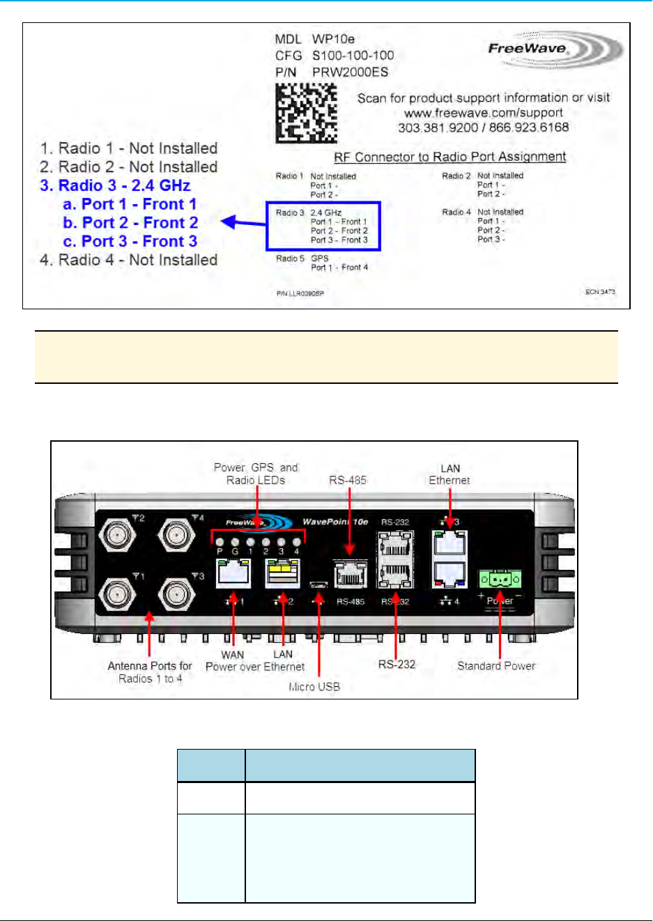
Chapter 1: Introduction
Note: The Port Assignment label designates which RF ports (the WavePoint™TNC
connectors) are used by which radio.
WavePoint™ Components
Data Connectors
Quantity Connector
4 RJ-45 connector for 4 Ethernet ports
3
RJ-45 connector for:
l2 - RS-232
l1 - RS-485
Page 22 of 171 LUM0063AA Rev 05/05/2014
This document is the property of FreeWave Technologies, Inc. and contains proprietary information owned by
FreeWave®. This document cannot be reproduced in whole or in part by any means without written permission from
FreeWave Technologies, Inc.

WavePoint 10e
Quantity Connector
1 Micro USB connector
1 Power connector used for DC power
RF Connectors
Module Maximum Connectors
900MHz RF modules 2 TNC connectors for spatial diversity*
2.4GHz RF modules 3 TNC connectors for 3x3 MIMO operation*
5.8GHz RF modules 3 TNC connectors for 3x3 MIMO operation*
Cellular module 1 RF connector – TNC
GPS module 1 RF connector – TNC
*One active RF port is a typical configuration.
Note: Refer to the label on the WavePoint 10e to determine the exact RF Connector
configuration. A description of the labels are in WavePoint 10e Labels on page 21.
Certified Antennas
AWavePoint™can have multiple radio modules installed, each potentially operating at different
frequencies. The model number reflects the number and frequency of the radios installed inside the
WavePoint™device and determines the type of antennas that can be used.
Important: The use of an antenna with a higher gain or a different type of antenna
other than those approved requires new FCC approval and should not be used.
Antenna Installation Warning
Important: This section provides the required FCC warning information for working
in proximity of the WavePoint™antennas.
1. All antenna installation and servicing must be performed by qualified technical personnel
only.
a. When servicing the antenna, or working at distances closer than those listed below,
verify the transmitter has been disabled.
b. Output is measured at the antenna terminal of the transmitter.
LUM0063AA Rev 05/05/2014 Page 23 of 171
This document is the property of FreeWave Technologies, Inc. and contains proprietary information owned by
FreeWave®. This document cannot be reproduced in whole or in part by any means without written permission from
FreeWave Technologies, Inc.

Chapter 1: Introduction
c. The antennas used for the WavePoint™must be fixed-mounted on outdoor
permanent structures to provide the minimum separation distances described in this
filing for satisfying RF exposure compliance requirements.
d. When applicable, RF exposure compliance may need to be addressed at the time of
licensing, as required by the responsible FCC Bureaus, including antenna co-location
requirements of §1.1307(b)(3).
2. Typically, the antenna connected to the transmitter is a directional (high gain) antenna,
fixed-mounted on the side or top of a building, or on a tower.
a. Depending upon the application and the gain of the antenna, the total composite power
could exceed 20 watts EIRP.
b. The antenna location must only be accessible by qualified technical personnel.
c. Under normal operating conditions, no other person can touch the antenna or
approach within 3.05 meters of the antenna.
Note: These antennas have been approved for use with WavePoint 10e and the
designated Tx Streams.
900MHz Antennas
Note: Separation minimum RF safety distances are required for FCC RF exposure
compliance.
900 MHz Antennas
Type Antenna Model Gain No of
Tx Streams
Channel
Size
Minimum RF
Safety Distance
Omni Wavelink - PRO902-11 11dBi 2 20 MHz 94cm
Yagi Wavelink - PRO890-16 16dBi 2 20 MHz 260cm
2.4GHz Antennas
Note: Separation minimum RF safety distances are required for FCC RF exposure
compliance.
2.4GHz Antennas
Type Antenna Model Gain No of
Tx Streams
Channel
Size
Minimum RF
Safety Distance
Dipole 98618MNXX001 5dBi 3 20 MHz 20cm
Page 24 of 171 LUM0063AA Rev 05/05/2014
This document is the property of FreeWave Technologies, Inc. and contains proprietary information owned by
FreeWave®. This document cannot be reproduced in whole or in part by any means without written permission from
FreeWave Technologies, Inc.

WavePoint 10e
2.4GHz Antennas
Type Antenna Model Gain No of
Tx Streams
Channel
Size
Minimum RF
Safety Distance
40 MHz
Omni ZDAQJ2400-12 12dBi 1
20 MHz
40 MHz
20cm
Yagi YA240016 16dBi 1
20 MHz
40 MHz
20cm
60 degree sector
RadioWaves
SEC-25V-60-17HP
17.5dBi 2
20 MHz
40 MHz
20cm
Directional Panel*
Superpass
SPAPG20
20.5dBi 2
20 MHz
40 MHz
25cm
Dish*
RadioWaves
SPD4 - 2.4NS
27dBi 3
20 MHz
40 MHz
40cm
*For radios deployed in the European Community under the CE mark, only antennas with a gain of
17.5dBi or less may be used.
5GHz Antennas
Note: Separation minimum RF safety distances are required for FCC RF exposure
compliance.
5GHz Antennas
Type Antenna Model Gain No of
Tx Streams
Channel
Size
Minimum RF
Safety Distance
Dipole 98618UNXX000 7dBi 1
20 MHz
40 MHz
20cm
Omni ZDAQJ5800-12 12dBi 1
20 MHz
40 MHz
20cm
Yagi Y5815 15dBi 1
20 MHz
40 MHz
26cm
LUM0063AA Rev 05/05/2014 Page 25 of 171
This document is the property of FreeWave Technologies, Inc. and contains proprietary information owned by
FreeWave®. This document cannot be reproduced in whole or in part by any means without written permission from
FreeWave Technologies, Inc.

Chapter 1: Introduction
5GHz Antennas
Type Antenna Model Gain No of
Tx Streams
Channel
Size
Minimum RF
Safety Distance
Directional Panel
RadioWaves
FP2-5-28
28.2dBi 2
20 MHz
40 MHz
71cm
Dish
RadioWaves
SPD4-5.2S
34.9dBi 3
20 MHz
40 MHz
154cm
Antenna Installation
Antennas must be professionally installed on a fixed, mounted, and permanent structure to satisfy
RF exposure requirements.
Warning! Any antenna placed outdoors must be properly grounded. Use
extreme caution when installing antennas and follow ALL manufacturer
instructions included with the antenna.
Mise en garde ! Toute antenne placée à l'extérieur doit être correctement
mise à la terre. Soyez très prudent lors de l'installation d'antennes et suivre
toutes les instructions du fabricant fournies avec l'antenne.
Per FCC regulations, any antenna used with transceivers must be an approved antenna that has
comparable performance parameters.
Placement Considerations
Placement of the WavePoint 10e is likely to have a significant impact on its performance. The key to
the overall robustness of the RF link is the height and alignment of the antenna. Other antennas in
close proximity are a potential source of interference. See Diagnostics and Troubleshooting on page
147 for more information.
FreeWave Recommends: In general, FreeWave units with a higher antenna placement have a
better communications link.
Use grid and dish antennas with low attenuation cable in lengths ranging from 3 to 100 feet.
To help optimize an antenna location, have FreeWave complete a free Path Site
study.
Contact a FreeWave sales representative for a Path Study form.
Email the completed form to pathstudy@freewave.com.
Page 26 of 171 LUM0063AA Rev 05/05/2014
This document is the property of FreeWave Technologies, Inc. and contains proprietary information owned by
FreeWave®. This document cannot be reproduced in whole or in part by any means without written permission from
FreeWave Technologies, Inc.

WavePoint 10e
Transmit Power Settings
The Transmit Power parameter is the output power of the transceiver.
Important: The information in this section describes the FCC maximum Equivalent
Isotropically Radiated Power (EIRP) regulations.
The transceiver output power level must be set to satisfy the maximum requirements
in the country the WavePoint 10e is installed in.
The installer is responsible for ensuring that an installation is within EIRP emission
limits.
When setting up the network, consider the power gain that an antenna may add and the power loss
through cabling. Adjust the Transmit Power on the transceiver so it does NOT exceed the
maximum EIRP for the regulating body where WavePoint 10e is installed. Use the tables to
determine the correct Transmit Power parameter setting for each transceiver in the network.
When calculating the power gain, use Equation 1 to determine the total output power at the
antenna.
Transceiver Output – Losses + Antenna Gain = Output Antenna Power
Equation 1
Note: Loss calculations should include cable, connectors, surge protectors, etc.
RF Loss
Cable losses for high frequency systems are one of the main losses to consider in Equation 1.
This table shows the RF loss at various cable lengths.
Example: Using the information in the table, a cable as short as 25 feet can have an
attenuation of almost 1dB.
Cable Type
Attenuation
(db/100 ft) Run Length (ft)
Total Run
Attenuation (dB)
LMR400 3.93 25 1.0
LMR500 3.154 25 0.8
LMR600 2.518 25 0.6
LMR900 1.709 25 0.4
LUM0063AA Rev 05/05/2014 Page 27 of 171
This document is the property of FreeWave Technologies, Inc. and contains proprietary information owned by
FreeWave®. This document cannot be reproduced in whole or in part by any means without written permission from
FreeWave Technologies, Inc.

Chapter 1: Introduction
WavePoint™ EIRP Limits
This table provides a summary of the FCC limits for the different frequencies available in
WavePoint™.
Note: See the www.fcc.gov site for the most up-to-date information.
EIRP Limits
Frequency Band
PTP
Max EIRP
(dBm)
PTP
Max EIRP
(watts)
PTMP
Max EIRP
(dBm)
PTMP
Max EIRP
(watts)
900 ISM (902-928 MHz) 36 4 36 4
2.4 ISM (2.4 - 2.483.5
GHz) 50 158 36 4
UNII - 1 (5.15 - 5.25 GHz) 22 0.16 22 0.16
UNII - 2a (5.25 - 5.35 GHz) 29 0.8 29 0.8
UNII - 2c (5.470 - 5.725
GHz) 29 0.8 29 0.8
UNII - 3 (5.725 - 5.850
GHz) 53 200 35 3.2
RF Considerations for 2.4GHz ISM Band
The FCC regulations for 2.4GHz ISM Band are different for Point-to-Point (PTP) and Point-to-Multi-
Point (PtMP) links.
Peak Power Output
The maximum peak output power of the intentional radiator cannot exceed 1.000 Watts.
Digital Transmission Systems (MHz) Output Limit (Watts)
2400-2483.5 1.000
Important: Point-to-Point applications operating in the 2400-2483.5MHz band may
employ transmitting antennas with directional gain greater than 6dBi provided the
maximum peak output power of the intentional radiator is reduced by 1dB for every
3dB that the directional gain of the antenna exceeds 6dBi.
Page 28 of 171 LUM0063AA Rev 05/05/2014
This document is the property of FreeWave Technologies, Inc. and contains proprietary information owned by
FreeWave®. This document cannot be reproduced in whole or in part by any means without written permission from
FreeWave Technologies, Inc.

WavePoint 10e
Example:
2.4GHz with a 24 inch dish has a maximum output of 24dBm.
2.4GHz with a 27 inch dish has a maximum output of 23dBm.
Point-to-Point Link
Note: The FCC permits a maximum of 36dBm EIRP when using a transmitter set to
30dBm.
However, for each 1dBm reduction in the transmitter power, the FCC permits an
increase in antenna gain of 3dBi.
Extrapolating this rule through different maximum power settings on the WavePoint™provides
these guidelines.
Guidelines
Maximum Power
from Transmitter
Maximum Antenna
Gain (dBi)
EIRP (dBm)
30dBm 6 36
29dBm 9 38
28dBm 12 40
27dBm 15 42
26dBm 18 44
25dBm 21 46
24dBm 24 48
23dBm 27 50
22dBm 30 52
Note: FreeWave has certified a dish antenna with a maximum gain of 27dBi.
This sets the maximum EIRP of a FreeWave system to 50 EIRP.
Dishes below 27dBi can be used with a corresponding reduction in total EIRP.
Point-to-Multi-Point Link
For Point-to-Multi-Point links, the FCC permits 1 Watt output power at the transceiver and 36dBm (4
Watts) at the antenna.
LUM0063AA Rev 05/05/2014 Page 29 of 171
This document is the property of FreeWave Technologies, Inc. and contains proprietary information owned by
FreeWave®. This document cannot be reproduced in whole or in part by any means without written permission from
FreeWave Technologies, Inc.
Chapter 1: Introduction
RF Considerations for 900MHz ISM Band
The 900MHz links requires these special considerations:
lA Path Study is needed to confirm the right RF characteristics of the link.
lThe noise floor should be sampled at each site using similar antennas to the ones
expected to be deployed.
WavePoint™ GUI to Actual RF Power
This table identifies the WavePoint™GUI settings on the Advanced Radio window and their
corresponding actual power out of the radio.
Note: Click Wireless LAN > Radios > Advanced to open the window.
GUI Setting
(dBm)
Actual Tx Power Out
of Radio (dBm)
11 23
10 22
9 21
8 20
7 19
6 18
5 17
GUI Setting
(dBm)
Actual Tx Power Out
of Radio (dBm)
18 30
17 29
16 28
15 27
14 26
13 25
12 24
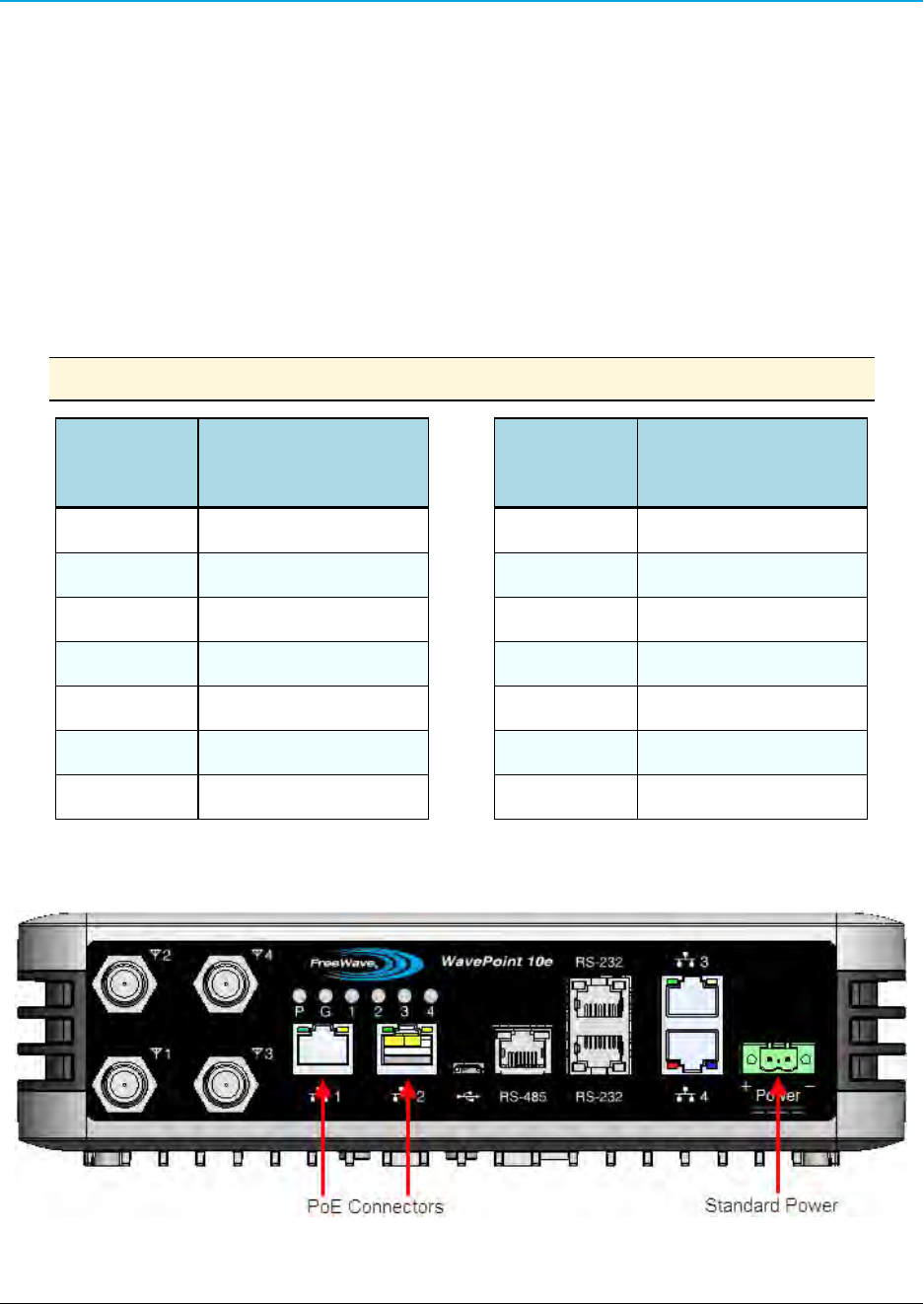
Connect Power
Use either of these options to provide the WavePoint™power:
Page 30 of 171 LUM0063AA Rev 05/05/2014
This document is the property of FreeWave Technologies, Inc. and contains proprietary information owned by
FreeWave®. This document cannot be reproduced in whole or in part by any means without written permission from
FreeWave Technologies, Inc.

WavePoint 10e
lConnect a CAT 5e Ethernet cable from an 802.3at (PoE+) source to one or both of the
Ethernet PoE Connector ports on the left side of the connector panel.
Note: Depending on the number of radios installed in the WavePoint 10e model,
it may require power through both ports.
Important: Power over Ethernet is only available on some models.
lConnect a power supply to the green Standard Power port on the far right side of the
connector panel. The WavePoint 10e requires power between 10.5Vdc-30Vdc, 24W.
Power Supply Cable
The power supply cable is a 2-wire, size 22AWG.
Screw Torque
For all connections, use these tightening torque minimum and maximum:
lMinimum: 0.22 Nm.
lMaximum: 0.25 Nm.
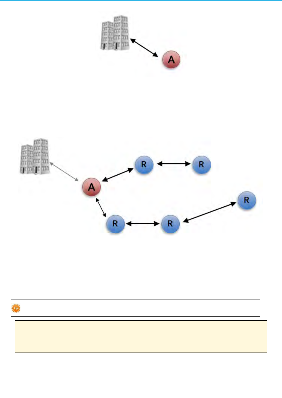
Network Deployment Scenarios
WavePoint 10e can be installed in a network to provide both wired and wireless access in Point-to-
Point and Point-to-Multipoint scenarios. This extends the Ethernet and real-time communication to
remote parts of the network.
These diagrams illustrate possible network deployment options for a WavePoint 10e using these
symbols:
Access Point
Client
Repeater
Wired Access
This provides a connection to a central office.
LUM0063AA Rev 05/05/2014 Page 31 of 171
This document is the property of FreeWave Technologies, Inc. and contains proprietary information owned by
FreeWave®. This document cannot be reproduced in whole or in part by any means without written permission from
FreeWave Technologies, Inc.
Chapter 1: Introduction
Wireless Access
Multiple Repeaters
WavePoint 10e provides wireless access by extending the distance of the network using back-to-
back Repeaters:
Connecting and Logging In
WavePoint 10e uses web pages for configuration.
Setup and configure the WavePoint 10e while it is in an easily accessible location.
Note: These instructions assume the computer has a static IP address assigned.
Change the computer's IP address to be within the same subnet as the default
address of the WavePoint 10e (192.168.1.1).
AWavePoint 10e from the factory has these user types:
Page 32 of 171 LUM0063AA Rev 05/05/2014
This document is the property of FreeWave Technologies, Inc. and contains proprietary information owned by
FreeWave®. This document cannot be reproduced in whole or in part by any means without written permission from
FreeWave Technologies, Inc.

WavePoint 10e
lAdministrator - Can view and change all configuration settings.
lGuest - Can view configuration settings but cannot save changes.
Connect WavePoint 10e to a Computer
Important: Initial setup requires a wired connection.
1. Verify the WavePoint 10e has power.
2. On the WavePoint 10e Connector Panel, connect a CAT 5e Ethernet cable from
Ethernet port 3 or 4 to a computer that has a web browser installed.
Note: Use a command line to ping 192.168.1.1 to ensure the WavePoint™is ready for
use.
Important: For 2.4 GHz WavePoint 10e devices, connect to a wireless connection
after the WLAN settings are configured.
3. On the connected computer, open a web browser.
4. In the web browser's navigation bar, enter http://192.168.1.1.
This is the WavePoint 10e factory default IP address.
Note: If the IP address was changed, enter that IP address in the navigation bar of the
browser to access the Configuration pages.
5. Enter the default User Name (admin) and Password (freewave).
User Names and Passwords are case sensitive.
Login Type Default Login Credentials
Administrator Username: admin
Password: freewave
Guest Username: guest
Password: freewave
Note: If the User Name or Password has changed, use the updated information
in the appropriate fields.
6. Click Login to view the Configuration pages.
7. Optional: See the Setting the Device IP Address and Subnet on page 38 procedure to
change the subnet address.
LUM0063AA Rev 05/05/2014 Page 33 of 171
This document is the property of FreeWave Technologies, Inc. and contains proprietary information owned by
FreeWave®. This document cannot be reproduced in whole or in part by any means without written permission from
FreeWave Technologies, Inc.
Chapter 1: Introduction
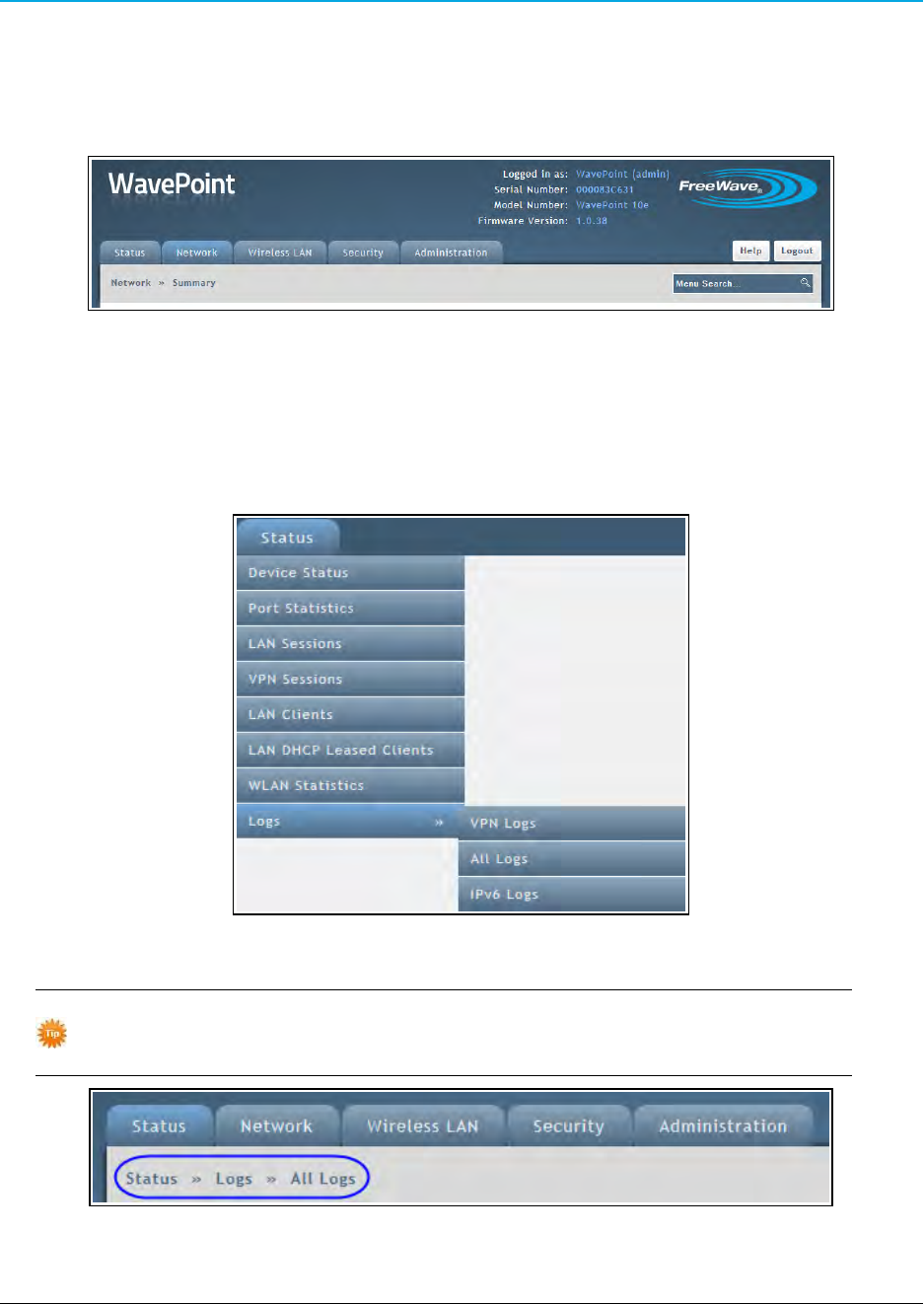
Configuration Pages
Each WavePoint 10e is configured through a set of web pages visible after log in. Functionality and
features are grouped in the menus across the top of the page.
WavePoint™ menus
Click a menu to view the menu and its sub-menus with links to individual Configuration pages. The
pages are used to change each feature of the WavePoint™configuration.
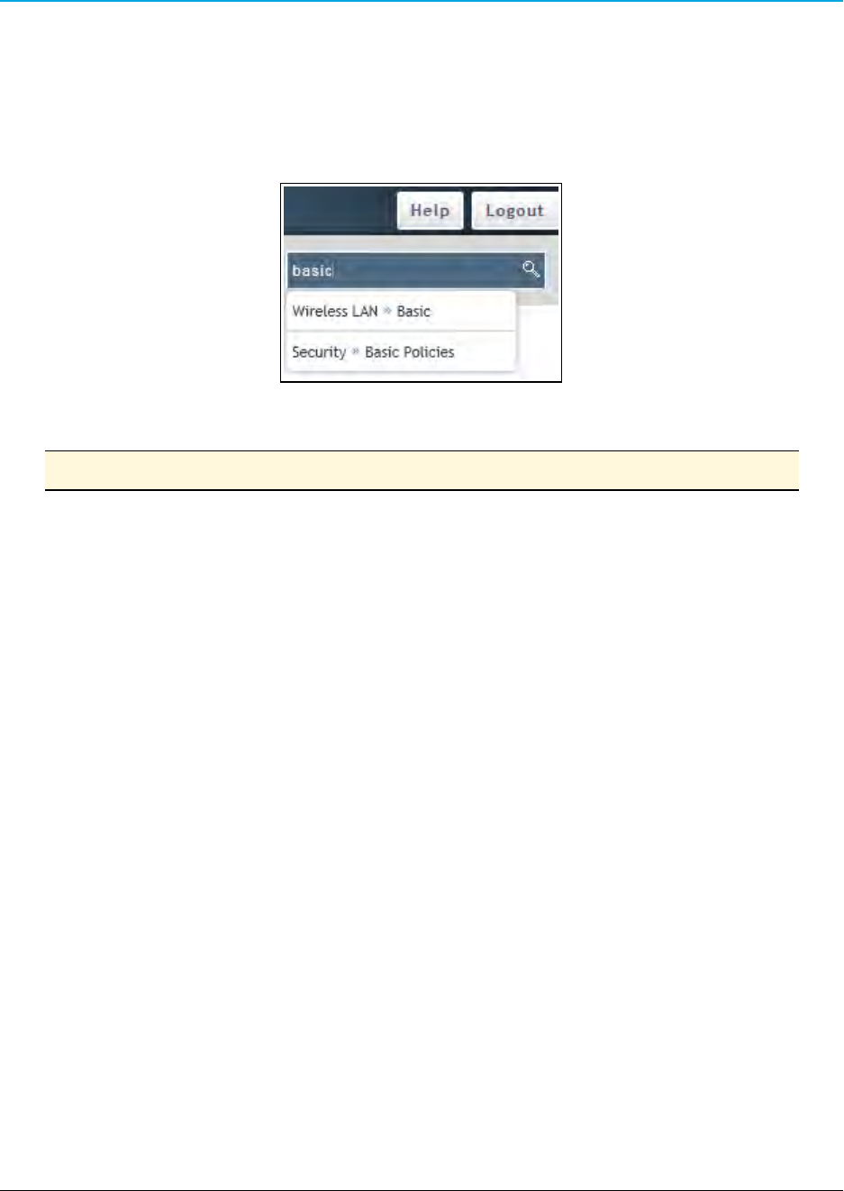
This image is an example of the Status > Logs menu.
Example: Status > Logs Menu and sub-menus
When navigating through the pages, the menu path (breadcrumbs) for the page is
shown under the menu tabs to help identify the page:
Example: Breadcrumbs
Page 34 of 171 LUM0063AA Rev 05/05/2014
This document is the property of FreeWave Technologies, Inc. and contains proprietary information owned by
FreeWave®. This document cannot be reproduced in whole or in part by any means without written permission from
FreeWave Technologies, Inc.
WavePoint 10e
Searching for Menus
Search for a menu by menu keyword using the Menu Search field located below the Logout
button.
WavePoint 10e searches and shows the menus that match the keywords entered in the field:
Example: Menu Search field
Note: The Auto Configure utility to configure the basic radio settings is not supported.
LUM0063AA Rev 05/05/2014 Page 35 of 171
This document is the property of FreeWave Technologies, Inc. and contains proprietary information owned by
FreeWave®. This document cannot be reproduced in whole or in part by any means without written permission from
FreeWave Technologies, Inc.

Page 36 of 171 LUM0063AA Rev 05/05/2014
This document is the property of FreeWave Technologies, Inc. and contains proprietary information owned by
FreeWave®. This document cannot be reproduced in whole or in part by any means without written permission from
FreeWave Technologies, Inc.

Chapter 2: Configuring Basic
WavePoint™ Network Features
This chapter provides information about:
lSetting an IP address that is unique in the network.
lDefining the subnet.
lConfiguring the optional DHCP server.
lReserving IP addresses within an address pool.
lEnabling, disabling, and configuring WAN ports and the wider network.
lSetting the WavePoint 10e mode.
LUM0063AARev 05/05/2014 Page 37 of 171
This document is the property of FreeWave Technologies, Inc. and contains proprietary information owned by
FreeWave®. This document cannot be reproduced in whole or in part by any means without written permission from
FreeWave Technologies, Inc.

Chapter 2: Configuring Basic WavePoint™ Network Features
Setting the Device IP Address and Subnet
For the WavePoint 10e to exist in the network, it must have a unique IP address and exist in the
correct subnet.
IPv4 Networks - Set the IP Address and Subnet
Reserved Subnets
Important: WavePoint™has reserved subnets that cannot be used to
administrate the WavePoint™device. These subnets are reserved for (Virtual
Access Points) VAPs.
The subnets that CANNOT be used are:
l192.168.2.0/24
l192.168.3.0/24
l192.168.4.0/24
Procedure
1. Follow the procedures for Connecting and Logging In on page 32
2. On the Network menu, click LAN > LAN IPv4 Setup.
3. In the IP Address Setup section, enter this information for the LAN:
a. Enter a unique IP address for the device.
The default setting is 192.168.1.1.
b. The default setting for the Subnet Mask is 255.255.255.0.
Accept the default setting unless subnetting is used.
Example: If the default setting of 255.255.255.0 is kept, all devices in the
network must have addresses where the first three sections of the address
match, but the last section is unique.
Addresses 10.0.1.201 and 10.0.1.202 are in the same subnet, but
10.0.2.201 is not included in the subnet.
c. The default option for the DHCP Setup Mode is DHCP None.
If applicable, select either the DHCP Relay or DHCP Server option when
configuring the device as an Access Point.
For more information about the DHCP Mode settings,see Enabling and Configuring
DHCP on page 39.
Page 38 of 171 LUM0063AA Rev 05/05/2014
This document is the property of FreeWave Technologies, Inc. and contains proprietary information owned by
FreeWave®. This document cannot be reproduced in whole or in part by any means without written permission from
FreeWave Technologies, Inc.

WavePoint 10e
Important: Write down the updated IP address to access this device through
the LAN or over a wireless connection.
4. Click Save to save the changes or Cancel to clear any changes without saving.
Note: When the IP address is changed and saved, the Configuration page no longer
responds because the IP address is saved to the WavePoint 10e and the
connection is lost.
To reconnect, enter the new IP address in the web browser window, verifying the
PC’s IP address is within the same subnet.
Enabling and Configuring DHCP
When configured and installed in a network as a router or a Network Address Translation (NAT)
device, the WavePoint 10e functions as a Dynamic Host Configuration Protocol (DHCP) server
when enabled in DHCP mode. This provides TCP/IP configuration to computers connected to the
LAN network.
The device can also be set to receive its IP address from a third-party DHCP
server.
IPv4 Addressing - Enable and Configure DHCP
1. Connect to the WavePoint 10e either through an Ethernet cable connected to Ethernet
port 3 or 4 or through the computer's wireless options.
2. Use a web browser to access the Configuration pages.
3. Set the radio mode to an Access Point.
See Configuring Wireless Communication on page 82 for instructions.
4. On the Network menu, click LAN IPv4 Setup.
5. In the DHCP Mode field, select a mode:
lNone - The DHCP server is disabled.
Select this option if:
lanother device in the network is the DHCP server or the network settings are
manually configured for all devices in the network.
lconfiguring the device as a client or repeater.
lDHCP Server - The DHCP server is enabled and it assigns IP addresses:
LUM0063AA Rev 05/05/2014 Page 39 of 171
This document is the property of FreeWave Technologies, Inc. and contains proprietary information owned by
FreeWave®. This document cannot be reproduced in whole or in part by any means without written permission from
FreeWave Technologies, Inc.

Chapter 2: Configuring Basic WavePoint™ Network Features
lwithin the range specified in the Starting IP Address and Ending IP Address
fields.
ladditional TCP/IP settings to any LAN device that requests a DHCP address.
lDHCP Relay - If enabled, LAN devices that request a DHCP address receive IP
address leases and corresponding information from a DHCP server on a different
subnet within the network.
lWavePoint 10e routes the request to the Gateway IP address specified in the
Relay Gateway field.
lUse this setting for devices in a wireless network that request IP addresses from
a third party DHCP server.
6. If the DHCP Server is the mode selected in Step 5, change these parameters to
configure the DHCP server:
a. Enter a Starting IP Address as the first inclusive IP addresses in a pool of
addresses the router can assign to a DHCP client.
The default starting address is 192.168.1.100.
Important: These addresses must be in the same IP address
subnet as the router’s IP address.
Note: Reserve part of the IP address range for devices with statically
assigned IP addresses in the network.
See Reserving IP Addresses on page 41 for more information.
b. Enter an Ending IP Address as the last inclusive IP addresses in a pool of
addresses the router can assign to a DHCP client.
The default ending address is 192.168.1.254.
c. If applicable, enter a Primary DNS Server and a Secondary DNS Server.
If the network uses a DNS server, enter the IP addresses of the domain name
system (DNS) servers, if available on the LAN.
d. If applicable, enter the Domain Name of the DHCP server.
e. Optional: If the network uses a WINS server, enter the IP address for the WINS
server or enter the server's IP address.
f. Enter the Lease Time, in hours, an IP address is assigned or leased.
Set this time as accurately as possible to ensure that unused IP
addresses are available for other requesting devices.
7. Click Save to save the changes or Cancel to clear any changes without saving.
Page 40 of 171 LUM0063AA Rev 05/05/2014
This document is the property of FreeWave Technologies, Inc. and contains proprietary information owned by
FreeWave®. This document cannot be reproduced in whole or in part by any means without written permission from
FreeWave Technologies, Inc.

WavePoint 10e
Reserving IP Addresses
If a WavePoint 10e is used in the network as a DHCP server to assign IP addresses, reserve part of
the IP address range for devices within the network for statically assigned IP addresses in the
network.
When the WavePoint 10e receives a request from an IP address from a device in the network, it
compares the hardware address to the MAC addresses saved in the reserved IP addresses list.
lIf a match exists, the WavePoint 10e assigns the requesting device the saved IP
addresses.
lIf a match is NOT found, the WavePoint 10e assigns the requesting device an IP address
from the range set in the LAN setup page.
Reserve IP Addresses in an IPv4 Network
1. Connect to the WavePoint 10e either through an Ethernet cable connected to Ethernet
port 3 or 4 or through the computer's wireless options.
2. Use a web browser to access the Configuration pages.
3. On the Network menu, click LAN > LAN IPv4 Reserved IPs.
The list of currently reserved IP addresses is shown.
4. Below the list of addresses, click Add New LAN IPv4 Reserved IP.
5. Enter the static IP Address to reserve.
6. Enter the MAC Address WavePoint 10e looks for when trying to determine if a
requesting device is assigned the corresponding IP address.
7. Click Save to save the changes or Cancel to clear any changes without saving.
Delete a Specific LAN Reserved IP Address
1. Connect to the WavePoint 10e either through an Ethernet cable connected to Ethernet
port 3 or 4 or through the computer's wireless options.
2. Use a web browser to access the Configuration pages.
3. On the Network menu, click LAN > LAN IPv4 Reserved IPs.
The list of currently reserved IP addresses is shown.
4. Right-click the address to remove and click Delete.
LUM0063AA Rev 05/05/2014 Page 41 of 171
This document is the property of FreeWave Technologies, Inc. and contains proprietary information owned by
FreeWave®. This document cannot be reproduced in whole or in part by any means without written permission from
FreeWave Technologies, Inc.

Chapter 2: Configuring Basic WavePoint™ Network Features
Delete all Reserved IP Addresses
Right-click anywhere in the table and click Select All > Delete.
Using Multiple WANs or a Single WAN
WavePoint 10e supports a maximum of two WANs. Setting up both WANs allows redundancy in
the WAN by setting up one WAN as a secondary to back up the first in case of a network failure.
Using two WANs also allows balancing the data traffic load across multiple links. This can improve
network performance if the environment requires a large amount of data be passed across the
WAN.
Indicate the Number of WANs in Use
1. Connect to the WavePoint 10e either through an Ethernet cable connected to Ethernet
port 3 or 4 or through the computer's wireless options.
2. Use a web browser to access the Configuration pages.
3. On the Network menu, click WAN > WAN Mode.
4. Select a Multi-WAN Use option:
lAuto-Rollover Using WAN Port - Enables the auto-failover if there is an error in
the primary WAN.
lSelect the WAN to use as the secondary, redundant network.
lSet how WavePoint 10e determines if a failure has occurred.
See Setting Up Auto Fail-Over in Multi-WAN Environments on page 50
lLoad Balancing - Use to balance the data traffic load across both WANs.
See Balancing Data Flow in Multi-WAN Environments on page 51 to select the type
of balancing to use.
lUsing Only Single WAN Port - Enables only the WAN port selected in the
adjacent drop-down list.
Note: Selecting this option does not allow for redundancy or load balancing
between two ports.
5. Click Save to save the changes or Cancel to clear any changes without saving.
Page 42 of 171 LUM0063AA Rev 05/05/2014
This document is the property of FreeWave Technologies, Inc. and contains proprietary information owned by
FreeWave®. This document cannot be reproduced in whole or in part by any means without written permission from
FreeWave Technologies, Inc.

WavePoint 10e
Configuring the WAN in an IPv4 Network
WavePoint 10e has two WAN ports that can be configured to have separate settings. Use the
settings on the WAN IPv4 pages to define the properties for each WAN port.
Defining WAN Connections Using Static IP Addresses
Assign a static IP address to the WavePoint 10e for WAN traffic.
Procedure
1. Connect to the WavePoint 10e either through an Ethernet cable connected to Ethernet
port 3 or 4 or through the computer's wireless options.
2. Use a web browser to access the Configuration pages.
3. On the Network menu, click WAN > WAN1 IPv4 Setup or WAN 2 IPv4 Setup.
4. In the Connection Type field, click Static.
5. In the Static IP section, enter this information for the static WAN connection:
a. IP Address - Enter the static IP address assigned by the ISP.
This address identifies the device to the ISP.
b. Subnet Mask - Enter the IPv4 Subnet Mask provided by the ISP or Network
Administrator.
c. Gateway IP Address - Enter the IP address of the ISP Gateway provided by
the ISP or Network Administrator.
6. In the Domain Name System (DNS) Servers section, enter the IP address of the
Primary and Secondary DNS servers.
A DNS server translates Internet names to numeric IP addresses.
Note: If the ISP does not transfer the IP address, obtain the address from them
and enter it manually into these fields.
7. In the MAC Address section, select the method the ISP uses to determine the local
Ethernet address of this WAN port:
lUse Default MAC - Select this option unless the ISP requires MAC authentication
and another MAC address has been previously registered with the ISP.
lClone your PC's MAC - Select this option to assign the MAC address of the
computer used to configure the WavePoint 10e.
lUse this MAC - Select this option if the ISP assigned a MAC address to use.
LUM0063AA Rev 05/05/2014 Page 43 of 171
This document is the property of FreeWave Technologies, Inc. and contains proprietary information owned by
FreeWave®. This document cannot be reproduced in whole or in part by any means without written permission from
FreeWave Technologies, Inc.

Chapter 2: Configuring Basic WavePoint™ Network Features
lIn the MAC Address field, enter a MAC address in this format:
XX:XX:XX:XX:XX:XX
where X is a number from 0 to 9 or an alphabetical letter between A and F.
8. Click Save to save the changes or Cancel to clear any changes without saving.
Defining WAN Connections Using DHCP
Using DHCP, the WavePoint 10e can obtain its IP settings automatically from the ISP or DHCP
server.
Procedure
1. Connect to the WavePoint 10e either through an Ethernet cable connected to Ethernet
port 3 or 4 or through the computer's wireless options.
2. Use a web browser to access the Configuration pages.
3. On the Network menu, click WAN > WAN1 IPv4 Setup or WAN 2 IPv4 Setup.
4. In the Connection Type field, click DHCP.
5. In the Dynamic IP (DHCP) section, enter the Host Name to send to the DHCP server.
The host-name string contains only the client's host name prefix.
The server appends the DNS domain name or domain-name options, if any, to derive the
fully qualified domain name.
6. In the Domain Name System (DNS) Servers section, select how to convert Internet
names (e.g., www.freewave.com) to IP addresses to route traffic to the correct resources
on the WAN.
lGet Dynamically from ISP - Select this option if the ISP did not assign a static
DNS IP address.
lUse These DNS Servers - Select this option if the ISP assigned a static DNS IP
address.
lEnter the Primary and Secondary DNS servers in the designated fields.
7. In the MAC Address section, select the method the ISP uses to determine the local
Ethernet address of this WAN port:
lUse Default MAC - Select this option unless the ISP requires MAC authentication
and another MAC address has been previously registered with the ISP.
lClone your PC's MAC - Select this option to assign the MAC address of the
computer used to configure the WavePoint 10e.
Page 44 of 171 LUM0063AA Rev 05/05/2014
This document is the property of FreeWave Technologies, Inc. and contains proprietary information owned by
FreeWave®. This document cannot be reproduced in whole or in part by any means without written permission from
FreeWave Technologies, Inc.

WavePoint 10e
lUse this MAC - Select this option if the ISP assigned a MAC address to use.
lIn the MAC Address field, enter a MAC address in this format:
XX:XX:XX:XX:XX:XX
where X is a number from 0 to 9 or an alphabetical letter between A and F.
8. Click Save to save the changes or Cancel to clear any changes without saving.
Defining WAN Connections Using PPPoE
Select this Internet connection type if the ISP uses Point-to-Point Protocol over Ethernet (PPPoE) to
establish its network connections. If the ISP uses PPPoE to manage its Internet connectivity, a
Username, Password, and additional information are provided. Use this information when defining
the connection type.
Procedure
1. Connect to the WavePoint 10e either through an Ethernet cable connected to Ethernet
port 3 or 4 or through the computer's wireless options.
2. Use a web browser to access the Configuration pages.
3. On the Network menu, click WAN > WAN1 IPv4 Setup or WAN 2 IPv4 Setup.
4. In the Connection Type field, click PPPoE.
5. In the Address Mode field, select an option:
lDynamic IP - Use if a static IP address has not been assigned.
The ISP automatically assigns an IP address.
lStatic IP - Use if the ISP has assigned a fixed (static or permanent) IP address.
lEnter the IP address and the Subnet Mask in the designated fields
6. Enter the Username and Password required to log in to the ISP.
7. Optional: In the Service field, distinguish the two servers using the same Username and
Password combination.
Note: With PPPoE, servers using IP addresses cannot be specified.
However, the particular server to connect to can be specified in the Service
field.
8. Select the Authentication Type to use:
lAuto-Negotiate lCHAP
lMS-CHAP lMS-CHAPv2
LUM0063AA Rev 05/05/2014 Page 45 of 171
This document is the property of FreeWave Technologies, Inc. and contains proprietary information owned by
FreeWave®. This document cannot be reproduced in whole or in part by any means without written permission from
FreeWave Technologies, Inc.

Chapter 2: Configuring Basic WavePoint™ Network Features
lPAP
9. Select a Reconnect Mode option:
lAlways On - Select this option to leave the connection active.
lOn Demand - Select this option to automatically end the connection if it is idle for a
specified number of minutes.
lEnter the number of minutes in the Maximum Idle Time field.
This feature is useful if the ISP charges based on the amount of connection
time.
10. Click Save to save the changes or Cancel to clear any changes without saving.
Defining WAN Connections Using PPTP
Select this Internet connection type to create a virtual private network (VPN).
Procedure
1. Connect to the WavePoint 10e either through an Ethernet cable connected to Ethernet
port 3 or 4 or through the computer's wireless options.
2. Use a web browser to access the Configuration pages.
3. On the Network menu, click WAN > WAN IPv4 Setup.
4. In the Wan Type field, select the WAN port to configure.
5. In the Address Mode field, select an option:
lDynamic IP - Select this option if a static IP address has not been assigned.
The ISP automatically assigns an IP address.
lStatic IP - Select this option if the ISP has assigned a fixed (static or permanent) IP
address.
lEnter the IP address and the Subnet Mask in the designated fields
6. Enter the Username and Password required to log in to the ISP.
7. Optional: In the Service field, distinguish the two servers using the same Username and
Password combination.
Note: With PPTP, servers using IP addresses cannot be specified.
However, the particular server to connect to can be specified in the Service
field.
8. Select the Authentication Type to use:
Page 46 of 171 LUM0063AA Rev 05/05/2014
This document is the property of FreeWave Technologies, Inc. and contains proprietary information owned by
FreeWave®. This document cannot be reproduced in whole or in part by any means without written permission from
FreeWave Technologies, Inc.

WavePoint 10e
lAuto-Negotiate lCHAP
lMS-CHAP lMS-CHAPv2
lPAP
9. Select a Reconnect Mode option:
lAlways On - Select this option to leave the connection active.
lOn Demand - Select this option to automatically end the connection if it is idle for a
specified number of minutes.
lEnter the number of minutes in the Maximum Idle Time field.
This feature is useful if the ISP charges based on the amount of connection
time.
10. In the Server Address field, enter the AAA radius server IP address.
11. In the MPPE Encryption field, enter the AAA radius server encryption information.
12. In the Split Tunnel field, enter the IP address of default gateway on remote network.
13. Click Save to save the changes or Cancel to clear any changes without saving.
Setting the Device Mode
The device mode establishes the routing mode between the LAN and the WAN.
Note: All inbound firewall rules are deleted if the setting between NAT and Router is
changed.
Procedure
1. Connect to the WavePoint 10e either through an Ethernet cable connected to Ethernet
port 3 or 4 or through the computer's wireless options.
2. Use a web browser to access the Configuration pages.
3. On the Network menu, click Network > Device Mode.
4. Select a mode:
lNAT - Network Address Translation (NAT) allows devices on a LAN to share a
single Internet connection.
LUM0063AA Rev 05/05/2014 Page 47 of 171
This document is the property of FreeWave Technologies, Inc. and contains proprietary information owned by
FreeWave®. This document cannot be reproduced in whole or in part by any means without written permission from
FreeWave Technologies, Inc.

Chapter 2: Configuring Basic WavePoint™ Network Features
lIn a NAT setup, devices on the LAN use a private IP address range. The WAN
port on the WavePoint 10e uses a single public IP address, hiding internal IP
address from locations on the Internet.
lSelect NAT if the Internet Service Provider (ISP) has provided only one IP
address.
lAssign any network device that connects through the WavePoint 10e an IP
address in a private subnet (e.g., 192.168.1.99).
lRouter - IP addresses on the LAN are not translated and are exposed on the
Internet.
lSelect this option if the ISP assigns an IP address for each device that connects
through the WavePoint 10e.
lAssign any device that connects through the WavePoint 10e an IP address in
the same subnet as the WAN.
lBridge - This option allows traffic from the LAN to the WAN without address
translation. The LAN and the WAN can be configured on different subnets.
Note: For WavePoint 10e to function as a DHCP Relay, it must be configured as
an Access Point and the device mode must be set to NAT.
5. Click Save to save the changes or Cancel to clear any changes without saving.
Page 48 of 171 LUM0063AA Rev 05/05/2014
This document is the property of FreeWave Technologies, Inc. and contains proprietary information owned by
FreeWave®. This document cannot be reproduced in whole or in part by any means without written permission from
FreeWave Technologies, Inc.

Chapter 3: Additional Data Networking
Features
Defining Physical WAN Port Settings
For each of the two WAN ports, these settings can be controlled:
lWhether the WavePoint 10e responds to accessibility requests.
lThe data transmission size through the port.
lThe control the port speed.
Procedure
1. Connect to the WavePoint 10e either through an Ethernet cable connected to Ethernet
port 3 or 4 or through the computer's wireless options.
2. Use a web browser to access the Configuration pages.
3. On the Administration menu, click Remote Management.
4. In the WANs Ping section, set the Respond to Ping field to On if the WavePoint 10e
should respond to accessibility requests from other devices.
Note: Pings are used primarily for troubleshooting network communications.
5. In the MTU Size field, select an option to set the maximum transmission allowed without
fragmentation:
LUM0063AARev 05/05/2014 Page 49 of 171
This document is the property of FreeWave Technologies, Inc. and contains proprietary information owned by
FreeWave®. This document cannot be reproduced in whole or in part by any means without written permission from
FreeWave Technologies, Inc.

Chapter 3: Additional Data Networking Features
lDefault - 1500 bytes.
lCustom - Enter the maximum transmission in bytes in the Custom MTU field
6. In the Port Speed field, select an option:
lAuto Sense - The optimal settings for the port are configured automatically based
on the device and the network.
l10, 100 or 1000 Base T Half Duplex - Data traffic is only allowed in one direction
at a time at the indicated speed (10 Mbps, 100 Mbps, and 1000 Mbps).
l10, 100 or 1000 Base T Full Duplex - Data traffic is allowed in both directions
(send and receive) at a time at the indicated speed (10 Mbps, 100 Mbps, and 1000
Mbps).
7. Click Save to save the changes or Cancel to clear any changes without saving.
Setting Up Auto Fail-Over in Multi-WAN Environments
If both WANs are used on the WavePoint 10e, one WAN port can be set to be the primary port for
all WAN traffic. The other WAN port is set as a back-up for redundancy purposes if the primary link is
interrupted.
Note: Configure both WAN ports for the appropriate IP network (IPv4 or IPv6) prior to
enabling and setting up the fail-over functionality.
The port designated as the backup (redundant) port remains disconnected until the primary port
experiences a failure. At that time, the WavePoint 10e directs all WAN traffic to the redundant port.
Procedure
1. Connect to the WavePoint 10e either through an Ethernet cable connected to Ethernet
port 3 or 4 or through the computer's wireless options.
2. Use a web browser to access the Configuration pages.
3. On the Network menu, click WAN > WAN Mode.
4. In the Multi-WAN Use section, click Auto Rollover Using WAN Port and select the
backup WAN from the drop-down list.
Page 50 of 171 LUM0063AA Rev 05/05/2014
This document is the property of FreeWave Technologies, Inc. and contains proprietary information owned by
FreeWave®. This document cannot be reproduced in whole or in part by any means without written permission from
FreeWave Technologies, Inc.

WavePoint 10e
5. In the WAN Failure Detection Method section, complete the information that indicates
when WAN traffic is rolled over to the selected WAN port:
a. Select a Method option:
lNone - There is no check for detecting WAN failures.
lThis option is valid only if the WAN mode is set to Load Balancing.
lDNS Lookup Using WAN DNS Servers - Detects failure of a WAN link
using the DNS servers configured in the Network > WAN1 or WAN2 IPv4
Setup pages.
lDNS Lookup Using DNS Servers - Uses a specific DNS server for
detecting WAN failure.
lEnter the IP addresses of the custom DNS servers for WAN1 and
WAN2 in the fields provided.
lPing the IP Addresses - Attempts to communicate with the IP addresses
listed in the WAN 1 and WAN 2 fields to determine if the primary WAN is still
connected.
b. Enter a Retry Interval that determines how frequently the WavePoint 10e
runs the check selected in the Method field.
c. In the Failover Threshold field, enter the number of times the check must fail
before the WAN traffic is directed to the redundant port.
6. Click Save to save the changes or Cancel to clear any changes without saving.
Balancing Data Flow in Multi-WAN Environments
If both WANs are used on the WavePoint 10e, use load balancing to take advantage of the
bandwidth available on the WANs simultaneously.
Procedure
1. Connect to the WavePoint 10e either through an Ethernet cable connected to Ethernet
port 3 or 4 or through the computer's wireless options.
2. Use a web browser to access the Configuration pages.
3. On the Network menu, click WAN > WAN Mode.
4. In the Multi-WAN Use section, click Load Balancing and select a balancing method:
lRound Robin - Use the bindings described in Restricting the Traffic Type for Each
WAN Port on page 52 to direct traffic to specific WANs.
LUM0063AA Rev 05/05/2014 Page 51 of 171
This document is the property of FreeWave Technologies, Inc. and contains proprietary information owned by
FreeWave®. This document cannot be reproduced in whole or in part by any means without written permission from
FreeWave Technologies, Inc.

Chapter 3: Additional Data Networking Features
Example: If one WAN has a more robust link than the other, direct the low-
latency information over that link and direct back ground information to the WAN
with the less robust link.
lSpill Over - Have the WAN 1 act as the primary link until a defined threshold set in
Step 3 is reached. When the WAN reaches the defined threshold, the additional
data is directed to WAN 2.
5. If Spill Over is selected as the load balancing method, complete the Spillover
Configuration section to further refine the distribution of data between the WANs:
a. Enter the Load Tolerance percentage between 20 and 80 of the maximum
bandwidth at which the data is sent to WAN 2.
Example: Set this field to 50 and the Max Bandwidth field to 1500 bytes.
When the bandwidth received on WAN 1 reaches 50 percent of 1500 bytes,
or 750 bytes, any additional data is directed to WAN2.
b. In the Max Bandwidth field, enter the number of bytes at which the data is sent
to WAN 2.
Example: Set this field to 1500 bytes and the Load Tolerance field to 50
percent. When the bandwidth received on WAN 1 reaches 50 percent of 1500
bytes, or 750 bytes, any additional data is directed to WAN2.
6. Click Save to save the changes or Cancel to clear any changes without saving.
Restricting the Traffic Type for Each WAN Port
Protocol bindings ensure a defined type of traffic is always sent over one of the two configured WAN
interfaces when more than one Gateway to the Internet is available.
lA protocol binding configuration can be disabled at any time.
See Enable or Disable a Protocol Binding Configuration on page 54
lA protocol binding configuration can be deleted.
See Delete a Protocol Binding Configuration on page 54.
Page 52 of 171 LUM0063AA Rev 05/05/2014
This document is the property of FreeWave Technologies, Inc. and contains proprietary information owned by
FreeWave®. This document cannot be reproduced in whole or in part by any means without written permission from
FreeWave Technologies, Inc.

WavePoint 10e
Configure a Traffic Restriction (Protocol Binding) for a WAN Port
1. Connect to the WavePoint 10e either through an Ethernet cable connected to Ethernet
port 3 or 4 or through the computer's wireless options.
2. Use a web browser to access the Configuration pages.
3. On the Network menu, select WAN > Protocol Bindings.
The current list of protocol settings is shown.
4. Do one of the following:
lEdit an existing binding - Right-click the status in the Protocol Bindings table
and select Edit.
lAdd a binding configuration - Click Add New Protocol Binding below the
Protocol Bindings table.
5. In the Service field, select one of the services available for Protocol Binding.
6. In the Local Gateway field, select the port that sets the local Gateway for this protocol
binding (either Dedicated WAN or Configurable WAN).
7. In the Source Network field, select the source of traffic on the port:
lAny - Traffic can come from any network.
lSingle Address - Limits traffic to one source.
lEnter the IP address of the source in the field provided.
lAddress Range - Allows computers within an IP address range to be a part of the
source network.
lEnter the first and last addresses in the range in the fields provided.
8. In the Destination Network field, select the destination of traffic on the port:
lAny - Traffic can go to any network.
lSingle Address - Limits traffic to one computer.
lEnter the IP address of the computer in the field provided.
lAddress Range - Allows computers within an IP address range to be a part of the
destination network.
lEnter the first and last addresses in the range in the fields provided.
9. Click Save to save the changes or Cancel to clear any changes without saving.
LUM0063AA Rev 05/05/2014 Page 53 of 171
This document is the property of FreeWave Technologies, Inc. and contains proprietary information owned by
FreeWave®. This document cannot be reproduced in whole or in part by any means without written permission from
FreeWave Technologies, Inc.

Chapter 3: Additional Data Networking Features
Enable or Disable a Protocol Binding Configuration
1. Connect to the WavePoint 10e either through an Ethernet cable connected to Ethernet
port 3 or 4 or through the computer's wireless options.
2. Use a web browser to access the Configuration pages.
3. On the Network menu, click WAN > Protocol Bindings.
In the Status field, the list of protocol settings are shown with the status of each setting.
4. Right-click the binding and select Enable or Disable, as necessary.
Delete a Protocol Binding Configuration
1. Connect to the WavePoint 10e either through an Ethernet cable connected to Ethernet
port 3 or 4 or through the computer's wireless options.
2. Use a web browser to access the Configuration pages.
3. On the Network menu, click WAN > Protocol Bindings.
In the Status field, the list of protocol settings are shown with the status of each setting.
4. Right-click the binding to remove and click Delete.
Binding an IP Address to a MAC Address
If the WavePoint 10e is configured as a DHCP server, and there are devices that connect to it that
require static IP addresses, the device can be set to assign the same address to those devices each
time they connect using IP MAC address binding.
Binding an IP address assignment to a single MAC address replicates a static IP
address, but is managed from a single location without having to physically assign
each device in the network a static IP.
As data flows through the network, if the WavePoint 10e sees packets with a mismatch in the IP
address or MAC address, it drops the packets.
Procedure
1. Connect to the WavePoint 10e either through an Ethernet cable connected to Ethernet
port 3 or 4 or through the computer's wireless options.
2. Use a web browser to access the Configuration pages.
3. On the Network menu, click IP-MAC Binding Setup.
The current list of bound IP addresses is shown.
Page 54 of 171 LUM0063AA Rev 05/05/2014
This document is the property of FreeWave Technologies, Inc. and contains proprietary information owned by
FreeWave®. This document cannot be reproduced in whole or in part by any means without written permission from
FreeWave Technologies, Inc.

WavePoint 10e
4. Do one of the following:
lEdit an existing binding rule - Right-click the address in the table and select
Edit.
lAdd an IP-MAC binding rule - Click Add New IP-MAC Binding below the
table.
5. In the Name field, enter a unique name.
Note: The name is shown in drop-down lists and other areas of the
Configuration pages that reference bindings
6. In the MAC Address field, enter the physical hardware address for the device associated
with this binding rule.
7. In the IP address field, enter the IP address for the device associated with this binding
rule.
8. Set the Log Dropped Packets option to On to enable logging packets before they are
dropped.
9. Set the Associate with DHCP Reserved IP option to On to add the IP address to the
Reserved IP address list for the DHCP server.
10. Click Save to save the changes or Cancel to clear any changes without saving.
Data Routing
Note: Data routing applies to networks with more than two devices.
Data can be defined how it is routed between the LAN and WAN in the network using:
lstatic (fixed) routes.
lthe Routing Information Protocol (RIP) which defines a dynamic route based on the
number of hops to get to a network location.
Defining Static Routing Rules
A static route is a fixed path defined on a router that is added to the routing table. When there is a
change in the network or a failure occurs between two network devices with static routing rules, data
does not reroute through a different path.
Note: Static routes are typically used in small networks or for lower bandwidth WAN
links.
If the network is large, Static Routing is likely not optimal because each route and
any redundant path information has to be added to each device in the network
LUM0063AA Rev 05/05/2014 Page 55 of 171
This document is the property of FreeWave Technologies, Inc. and contains proprietary information owned by
FreeWave®. This document cannot be reproduced in whole or in part by any means without written permission from
FreeWave Technologies, Inc.

Chapter 3: Additional Data Networking Features
Define a Static IPv4 Route
1. Connect to the WavePoint 10e either through an Ethernet cable connected to Ethernet
port 3 or 4 or through the computer's wireless options.
2. Use a web browser to access the Configuration pages.
3. On the Network menu, click Routing > Static Route.
4. Do one of the following:
lEdit an existing Static Route - Right-click an existing Static Route and click
Edit.
lAdd a new Static Route - Click Add New IPv4 Static Route below the
Available IPv4 Static Route table.
5. Enter a unique Name that defines the route's use.
Note: The name entered here is shown in the Static Route table.
6. Enter the Destination IP address of the destination device.
7. Enter the Subnet Mask of the destination device.
8. Select the physical network Interface this route is accessible through.
9. Enter the IP address of the Gateway device that will route the data to the destination
device.
Note: This could be a third-party router, a computer, or another WavePoint 10e
device.
10. Use the Metric field to define the route's priority.
If multiple routes to the same destination exist, the device uses the route with the lowest
metric.
If this route is a direct connection, set to 1.
99 is the maximum entry allowed.
11. Change the Active field for the route to either On or Off.
This selection indicates if the route is currently active (On) or inactive (Off).
On activates this route.
Off retains this routes as defined, but it is not active.
12. Set the Private option to On to limit access to the LAN only.
Note: Static routes set as Private are not forwarded to other routing tables in the
network if Routing Internet Protocol (RIP) is used.
Page 56 of 171 LUM0063AA Rev 05/05/2014
This document is the property of FreeWave Technologies, Inc. and contains proprietary information owned by
FreeWave®. This document cannot be reproduced in whole or in part by any means without written permission from
FreeWave Technologies, Inc.

WavePoint 10e
For more information about defining RIP settings, see Defining Routing
Internet Protocol Rules.
13. ClickSave to save the changes and send them to the WavePoint 10e or click the Xin the
upper right corner to clear any changes without saving.
Delete an Existing Static Route
1. Connect to the WavePoint 10e either through an Ethernet cable connected to Ethernet
port 3 or 4 or through the computer's wireless options.
2. Use a web browser to access the Configuration pages.
3. On the Routing menu, click Static Route.
The list of currently defined static routes is shown in the table
4. Right-click the static route to remove and click Delete.
To delete all the static routes, right-click anywhere in the table and click
Select All > Delete.
5. Click Save to save the changes or Cancel to clear any changes without saving.
Defining Routing Internet Protocol Rules
The Routing Information Protocol (RIP) sends complete routing table information out to all active
interfaces every 30 seconds and uses the hop count to determine the fastest way to reach a remote
network.
RIP is typically used in larger networks because:
lrouting table information is updated from a router automatically.
lit does not require manual updates of routing information at each location in the network
when a device is added or replaced.
The selected RIP version is dependent on the requirements for the specific network and whether the
routing table information is sent as a broadcast or a multicast.
Note: WavePoint 10e supports both RIPv1 and RIPv2.
Define RIP in IPv4 Networks
1. Connect to the WavePoint 10e either through an Ethernet cable connected to Ethernet
port 3 or 4 or through the computer's wireless options.
2. Use a web browser to access the Configuration pages.
LUM0063AA Rev 05/05/2014 Page 57 of 171
This document is the property of FreeWave Technologies, Inc. and contains proprietary information owned by
FreeWave®. This document cannot be reproduced in whole or in part by any means without written permission from
FreeWave Technologies, Inc.

Chapter 3: Additional Data Networking Features
3. On the Network menu, click Routing > RIP.
4. In the IPv4 RIP Configuration section, set the Enabled option to On.
5. In the RIP Version field, select either RIPv1 or RIPv2.
6. Select an Authentication method:
lNone - No authentication is used when sending routing table information.
lThis is the default setting for both RIP versions.
lIt is the only option available if RIPv1 is selected. RIPv1 does not support
authentication.
lSimple - Includes a plain-text key in the transmitted packet.
lThe receiving device uses the text key to authenticate the request.
lIn the Authentication Key field, enter the plain-text key.
lMD5 - Includes the key in an encoded checksum within the transmitted packet.
lThe receiving device uses the key to verify the checksum.
lIn the MD5 Key ID field, enter the unique MD5 key ID.
lIn the MD5 Authentication Key field, enter the key. The encoding into the
checksum happens after you click Save.
Important: Authentication requires all routers in a RIP network or subnet to
have the same Authentication Type and Key configured.
If the keys do NOT match, the device rejects the packet.
7. Click Save to save the changes or Cancel to clear any changes without saving.
Virtual Local Area Networks (VLANs)
Use WavePoint 10e to isolate areas of the larger network by allocating various traffic to VLANs. A
WavePoint 10e VLAN has similar physical attributes as a LAN, and each VLAN is mapped to a
subnet within the network so that associated traffic passes through a physical port to a VLAN.
By default, VLANs are disabled in the WavePoint 10e. Follow these steps to configure VLANs in
the network:
1. Enabling VLANs on page 59
2. Defining VLANs in the Network on page 59
3. Mapping VLANs to LAN Subnets on page 60
4. Associating Port Traffic to a VLAN on page 62
Page 58 of 171 LUM0063AA Rev 05/05/2014
This document is the property of FreeWave Technologies, Inc. and contains proprietary information owned by
FreeWave®. This document cannot be reproduced in whole or in part by any means without written permission from
FreeWave Technologies, Inc.

WavePoint 10e
Enabling VLANs
By default, VLANs are disabled in the WavePoint 10e.
VLANs must be enabled before configuring the VLANs through the WavePoint 10e.
Procedure
1. Connect to the WavePoint 10e either through an Ethernet cable connected to Ethernet
port 3 or 4 or through the computer's wireless options.
2. Use a web browser to access the Configuration pages.
3. On the Network menu, click VLANs > Multi-VLANs Subnets.
4. Set the Enable VLAN field to On.
5. Click Save to save the changes or Cancel to clear any changes without saving.
Defining VLANs in the Network
When designing the network and its segmenting areas, define the potential VLANs using the
VLANs > Available VLANs page.
Procedure
1. Connect to the WavePoint 10e either through an Ethernet cable connected to Ethernet
port 3 or 4 or through the computer's wireless options.
2. Use a web browser to access the Configuration pages.
3. On the Network menu, click VLANs > Available VLANs.
The list of currently defined VLANs is shown.
4. Do one of the following:
lEdit an existing VLAN - Right-click an existing VLAN and click Edit.
lAdd a VLAN - Below the Available VLANs table, click Add New Available
VLAN.
5. In the Name field, enter a unique identifier used for management purposes.
6. In the ID field, enter a numeric value associated with the VLAN.
This value is used both for management and to update the Ethernet packet header for
member device traffic forwarded through this VLAN.
7. In the Inter-VLAN Routing Enabled field, select On to run traffic between other VLANs
that have this option set to On.
LUM0063AA Rev 05/05/2014 Page 59 of 171
This document is the property of FreeWave Technologies, Inc. and contains proprietary information owned by
FreeWave®. This document cannot be reproduced in whole or in part by any means without written permission from
FreeWave Technologies, Inc.

Chapter 3: Additional Data Networking Features
Note: After defining a VLAN configuration, only the Inter-VLAN Routing setting
can be changed.
To change the Name or ID, delete the VLAN configuration and add a new
one with the correct parameters.
8. Click Save to save the changes or Cancel to clear any changes without saving.
Delete an Available VLAN
1. On the Network menu, click VLAN > Available VLANs.
The list of defined VLANs is shown.
2. Right-click the VLAN to remove and click Delete.
To delete all VLANs other than the out of the box defaults, right-click
anywhere in the table and click Select All > Delete.
Mapping VLANs to LAN Subnets
lEach configured VLAN ID can map directly to a subnet within the LAN.
lEach LAN port can be assigned a unique IP address.
lA VLAN specific DHCP server can be configured to assign IP address leases to devices
on this VLAN.
Procedure
1. Connect to the WavePoint 10e either through an Ethernet cable connected to Ethernet
port 3 or 4 or through the computer's wireless options.
2. Use a web browser to access the Configuration pages.
3. On the Network menu, click VLAN > Multi-VLAN Subnets.
The available VLAN IDs are shown in the table.
4. Right-click the VLAN ID to configure and click Edit.
5. In the Multi-VLAN Subnet section, complete this subnet information:
a. Enter the IP Address associated with the port assigned with this VLAN ID.
b. Enter the Subnet Mask for the IP address.
6. In the DHCP Setup section, select a VLAN-specific DHCP mode:
lNone - The computers on the VLAN are configured with static IP addresses or are
configured to use another DHCP server.
Page 60 of 171 LUM0063AA Rev 05/05/2014
This document is the property of FreeWave Technologies, Inc. and contains proprietary information owned by
FreeWave®. This document cannot be reproduced in whole or in part by any means without written permission from
FreeWave Technologies, Inc.

WavePoint 10e
lDHCP Server - The DHCP server is enabled for the VLAN. It assigns an IP
address within the range specified in the Starting IP Address and Ending IP
Address fields to any network device that requests a DHCP address through the
VLAN.
lContinue with Step 7.
lDHCP Relay - If enabled, devices in the VLAN that request a DHCP address can
also receive IP address leases and corresponding information from a DHCP server
on a different subnet.
lIn the Relay Gateway field, enter the IP address of the remote DHCP server.
lWhen VLAN devices make DHCP requests, the request is passed to the
Relay Gateway IP address.
lContinue with Step 7.
7. If the DHCP Server was selected as the DHCP Setup mode in Step 6, set these
parameters to configure the VLAN-specific DHCP server:
a. In the Starting IP Address field, enter the first inclusive IP addresses the server
can assign an address to.
b. In the Ending IP Address field, enter the last inclusive IP addresses the server
can assign an address to.
Important: These addresses must be in the same IP address subnet
as the router’s VLAN IP address.
c. If available, enter the Primary DNS Server and Secondary DNS Server IP
addresses of the domain name system (DNS) servers, if available on the VLAN.
d. Optional: Enter the Domain Name of the DHCP server.
e. Optional: Enter the WINS Server IP address or the Windows NetBIOS server if the
network has one.
f. Enter the Lease Time, in hours, an IP address is assigned or leased, to a device in
the network.
Set this time as accurately as possible to allow unused IP addresses
to be available for other devices.
8. ClickSave to save the changes and send them to the WavePoint 10e or click the Xin the
upper right corner to clear any changes without saving.
LUM0063AA Rev 05/05/2014 Page 61 of 171
This document is the property of FreeWave Technologies, Inc. and contains proprietary information owned by
FreeWave®. This document cannot be reproduced in whole or in part by any means without written permission from
FreeWave Technologies, Inc.

Chapter 3: Additional Data Networking Features
Associating Port Traffic to a VLAN
Associate a physical port on the WavePoint 10e to a specific VLAN to tag the traffic that flows out of
a port to a specific VLAN ID.
Note: The Enable VLAN option in the Network > VLAN > Multi-VLAN Subnets
page must be set to On to associate a port to a VLAN.
Procedure
1. Connect to the WavePoint 10e either through an Ethernet cable connected to Ethernet
port 3 or 4 or through the computer's wireless options.
2. Use a web browser to access the Configuration pages.
3. On the Network menu, click VLAN > Port Based VLANs.
The current VLAN associations for both the LAN and WAN ports are shown.
4. Right-click one of the physical ports or a WAN device and click Edit.
5. In the Mode field, select a VLAN mode:
lAccess - Isolates this port from other VLANs.
lThis is the default setting.
lAll data going into and out of the port is untagged.
lTraffic through a port in Access mode appears like any other Ethernet frame.
lGeneral - Allows the port to become a member of a user-selectable set of VLANs.
lThe port sends and receives data that is tagged or untagged with a VLAN ID.
lIf the data into the port is untagged, it is assigned the defined PVID.
lAll tagged data sent out of the port with the same PVID is untagged.
lTrunk - Multiplexes traffic for multiple VLANs over the same physical link.
lAll data going into and out of the port is tagged.
lUntagged data coming into the port is not forwarded, except for the default
VLAN with a PVID of 1, which is untagged.
6. If the Mode is set to General in the PVID field, enter the default VLAN ID assigned to the
port or WAN device. This indicates the VLAN segment this port or WAN device is
connected to.
7. If the Mode is set to General or Trunk, select the VLANs the traffic to or from this port can
be routed to.
Page 62 of 171 LUM0063AA Rev 05/05/2014
This document is the property of FreeWave Technologies, Inc. and contains proprietary information owned by
FreeWave®. This document cannot be reproduced in whole or in part by any means without written permission from
FreeWave Technologies, Inc.

WavePoint 10e
The available VLAN membership options are determined by the list of available VLANs
that have the Inter-VLAN Routing Enable option set to On.
For more information, see Defining VLANs in the Network on page 59.
8. ClickSave to save the changes and send them to the WavePoint 10e or click the Xin the
upper right corner to clear any changes without saving.
LUM0063AA Rev 05/05/2014 Page 63 of 171
This document is the property of FreeWave Technologies, Inc. and contains proprietary information owned by
FreeWave®. This document cannot be reproduced in whole or in part by any means without written permission from
FreeWave Technologies, Inc.

Chapter 3: Additional Data Networking Features
WaveMesh
Using WavePoint™to create a WaveMesh provides:
lA machine to machine (M2M) solution.
lA self-healing environment.
lMultiple paths for quicker response.
lRedundancy support for the network.
lFault tolerance.
Important: Only the non-root devices can be changed.
The WavePoint™configured in Client mode must be the endpoint of the network
for M2M.
WaveMesh Methods
These are the methods for creating a WaveMesh:
lWaveMesh using Auto Selection Method on page 66
lWaveMesh using Branch Selection Method on page 69
lWaveMesh using a List Selection Method on page 72
Page 64 of 171 LUM0063AA Rev 05/05/2014
This document is the property of FreeWave Technologies, Inc. and contains proprietary information owned by
FreeWave®. This document cannot be reproduced in whole or in part by any means without written permission from
FreeWave Technologies, Inc.
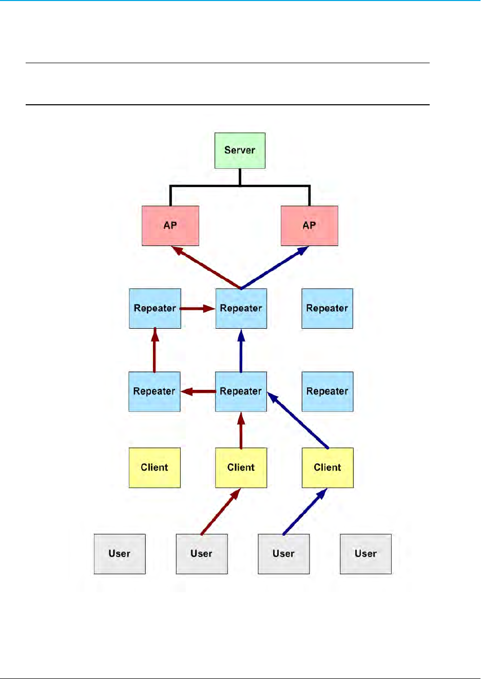
WavePoint 10e
Example: WaveMesh Routing Diagram
This diagram provides a basic example of how the WaveMesh network functions.
Important: The WaveMesh routing is a multi-route network.
This diagram provides only two possible solutions.
Example: WaveMesh Routing Diagram
LUM0063AA Rev 05/05/2014 Page 65 of 171
This document is the property of FreeWave Technologies, Inc. and contains proprietary information owned by
FreeWave®. This document cannot be reproduced in whole or in part by any means without written permission from
FreeWave Technologies, Inc.

Chapter 3: Additional Data Networking Features
WaveMesh using Auto Selection Method
This procedure defines the WavePoint™WaveMesh using the default Auto Selection Method to
allow the non-root device to locate the optimal route to the root device.
1. On the Wireless LAN menu, click Parent Configuration.
Wireless LAN > Parent Configuration menu
The Parent Selection Profile window opens.
Parent Selection Profile window
2. Right-click the device to configure.
3. On the right-click menu, click Edit.
Page 66 of 171 LUM0063AA Rev 05/05/2014
This document is the property of FreeWave Technologies, Inc. and contains proprietary information owned by
FreeWave®. This document cannot be reproduced in whole or in part by any means without written permission from
FreeWave Technologies, Inc.
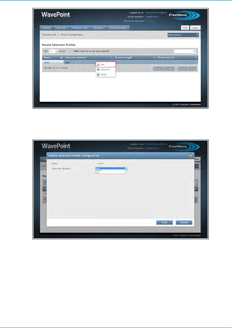
WavePoint 10e
Right-click >Edit menu
The Parent Selection Profile Configuration dialog opens.
Parent Selection Profile Configuration dialog
4. Click the Selection Method list box arrow and select an option.
In this procedure, accept the Auto default.
lAuto - Accept this default to allow the non-root device to locate the optimal route to
the root device.
Using Auto, the device can connect to any of the parents it sees in the network.
lBranch - Select this option to define the number of hops the non-root device is
required to use to locate the root device.
This option forces the non-root device to use a specific path.
LUM0063AA Rev 05/05/2014 Page 67 of 171
This document is the property of FreeWave Technologies, Inc. and contains proprietary information owned by
FreeWave®. This document cannot be reproduced in whole or in part by any means without written permission from
FreeWave Technologies, Inc.
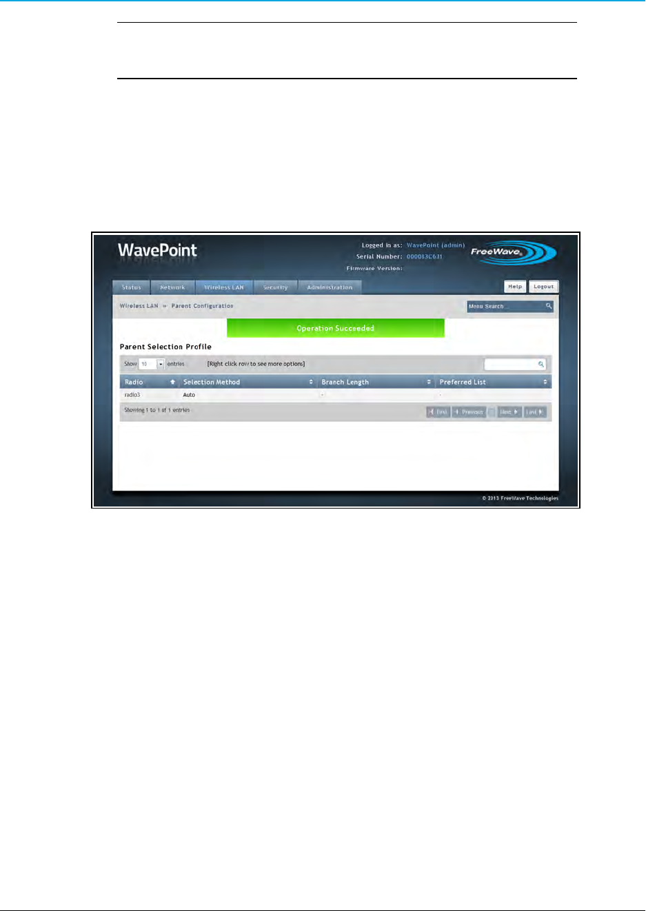
Chapter 3: Additional Data Networking Features
Important: If the Branch is not configured correctly, it could cause a
network failure if one device fails. Plan the paths carefully!
lList – Select this option to use the MAC Addresses of the Repeaters to define a
path to the root device.
The MAC Addresses are listed in the preferred order.
5. Click Save to accept the change and close the dialog.
The Parent Selection Profile window returns showing the accepted Selection Method
assigned to the device.
Parent Selection Profile window with a successful Auto WaveMesh
Page 68 of 171 LUM0063AA Rev 05/05/2014
This document is the property of FreeWave Technologies, Inc. and contains proprietary information owned by
FreeWave®. This document cannot be reproduced in whole or in part by any means without written permission from
FreeWave Technologies, Inc.
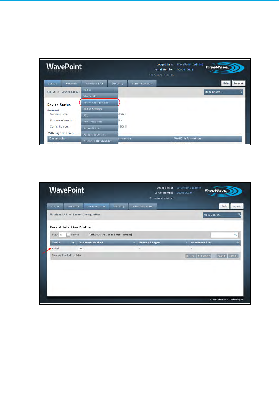
WavePoint 10e
WaveMesh using Branch Selection Method
This procedure establishes the WavePoint™WaveMesh using a defined number of hops the non-
root device is required to use to locate the root device.
1. On the Wireless LAN menu, click Parent Configuration.
Wireless LAN > Parent Configuration menu
The Parent Selection Profile window opens.
Parent Selection Profile window
2. Right-click the device to configure.
3. On the right-click menu, click Edit.
LUM0063AA Rev 05/05/2014 Page 69 of 171
This document is the property of FreeWave Technologies, Inc. and contains proprietary information owned by
FreeWave®. This document cannot be reproduced in whole or in part by any means without written permission from
FreeWave Technologies, Inc.
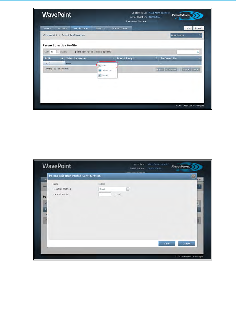
Chapter 3: Additional Data Networking Features
Right-click >Edit menu
The Parent Selection Profile Configuration dialog opens.
4. Click the Selection Method list box arrow and select Branch.
The Parent Selection Profile Configuration dialog refreshes.
Parent Selection Profile Configuration dialog with Branch Selection Method
5. In the Branch Length text box, enter the maximum number of hops the non-root device is
required to use to locate the root device.
The maximum is 10 hops.
In this example procedure, change the Branch Length to 8
Page 70 of 171 LUM0063AA Rev 05/05/2014
This document is the property of FreeWave Technologies, Inc. and contains proprietary information owned by
FreeWave®. This document cannot be reproduced in whole or in part by any means without written permission from
FreeWave Technologies, Inc.
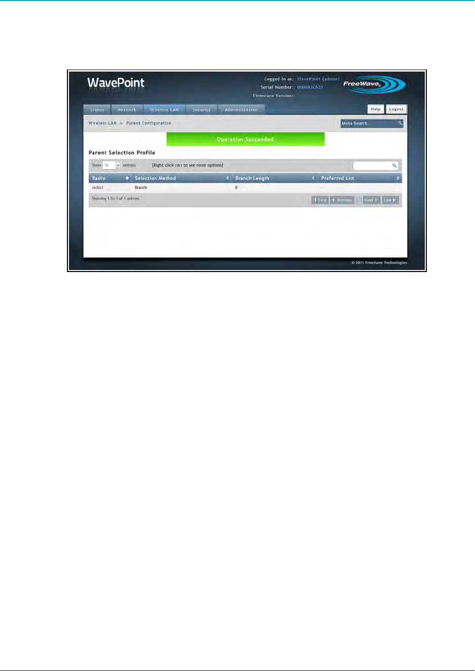
WavePoint 10e
6. Click Save to accept the change and close the dialog.
The Parent Selection Profile window returns showing the accepted Selection Method
assigned to the device.
Parent Selection Profile window with a successful Branch WaveMesh
LUM0063AA Rev 05/05/2014 Page 71 of 171
This document is the property of FreeWave Technologies, Inc. and contains proprietary information owned by
FreeWave®. This document cannot be reproduced in whole or in part by any means without written permission from
FreeWave Technologies, Inc.
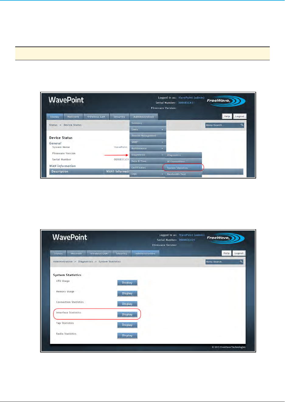
Chapter 3: Additional Data Networking Features
WaveMesh using a List Selection Method
This procedure defines the WavePoint™WaveMesh using the MAC Addresses of the Repeaters
to define a path to the root device
Note: The MAC Addresses are listed in the preferred order.
1. On the Administration menu, click Diagnostics > System Statistics.
Administration > Diagnostics > System Statistics menu
The System Statistics window opens.
2. Click the Interface Statistics Display button.
Click the Interface Statistics Display button.
The Interface Statistics dialog opens.
Page 72 of 171 LUM0063AA Rev 05/05/2014
This document is the property of FreeWave Technologies, Inc. and contains proprietary information owned by
FreeWave®. This document cannot be reproduced in whole or in part by any means without written permission from
FreeWave Technologies, Inc.
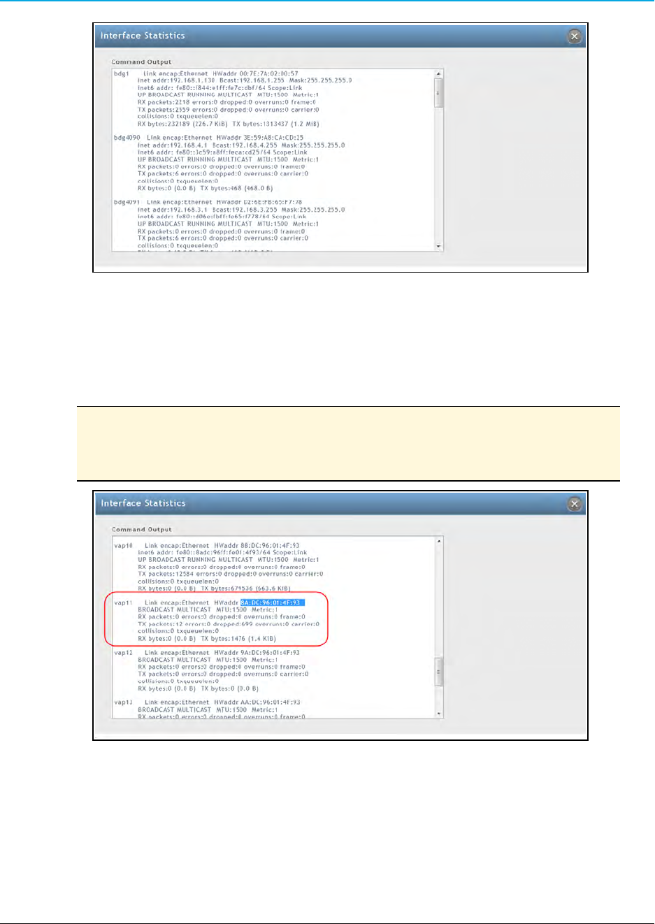
WavePoint 10e
Interface Statistics dialog
3. Scroll down the dialog to locate the vap10 (upstream) and vap11 (downstream)
information.
4. Highlight the VAP address to use in the WaveMesh.
Note: The Interface Statistics dialog box shown here is only for the
WavePoint™model WP10e-S100-100-100.
Other WavePoint 10e devices will use different VAP number.
Interface Statistics dialog box with highlighted VAP11 address.
3. Press <Ctrl+C> to copy the address to the clipboard.
This address is used in Step 10.
4. On the Wireless LAN menu, click Parent Configuration.
LUM0063AA Rev 05/05/2014 Page 73 of 171
This document is the property of FreeWave Technologies, Inc. and contains proprietary information owned by
FreeWave®. This document cannot be reproduced in whole or in part by any means without written permission from
FreeWave Technologies, Inc.
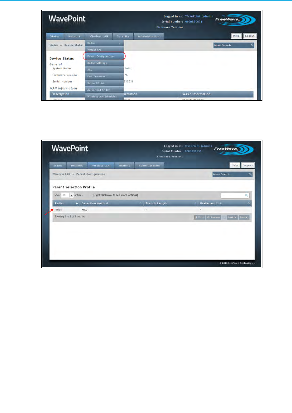
Chapter 3: Additional Data Networking Features
Wireless LAN > Parent Configuration menu
The Parent Selection Profile window opens.
Parent Selection Profile window
5. Right-click the device to configure.
6. On the right-click menu, click Edit.
Page 74 of 171 LUM0063AA Rev 05/05/2014
This document is the property of FreeWave Technologies, Inc. and contains proprietary information owned by
FreeWave®. This document cannot be reproduced in whole or in part by any means without written permission from
FreeWave Technologies, Inc.
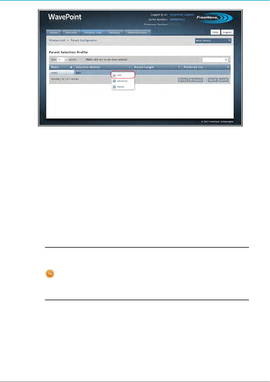
WavePoint 10e
Right-click >Edit menu
The Parent Selection Profile Configuration dialog opens.
7. Click the Selection Method list box arrow and select List.
The Parent Selection Profile Configuration dialog refreshes with the MAC ID
Addresses listed in the preferred order.
8. Click the Preferred List list box arrow and select an option:
lBest in List - Select this option to have the WavePoint™WaveMesh pick the best
parent MAC IDs out of the ones defined in that list.
lThis picks the best route out of the list based on the Auto selection defined
under the Auto Schedule Method based on RSSI and hop count.
Best in List is similar to the Auto Scheduled Method except that it
allows exclusion of any parents the WavePoint™device is not to be
connected to.
Using the Auto Scheduled Method, the device can connect to any
of the parents it sees in the network.
lFollow List Priority - Select this option to have the WavePoint™WaveMesh
route through the connection list in chronological order (e.g., MAC ID 1 first, then
MAC ID 2, MAC ID 3, etc.)
LUM0063AA Rev 05/05/2014 Page 75 of 171
This document is the property of FreeWave Technologies, Inc. and contains proprietary information owned by
FreeWave®. This document cannot be reproduced in whole or in part by any means without written permission from
FreeWave Technologies, Inc.
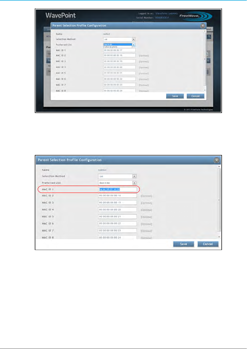
Chapter 3: Additional Data Networking Features
Parent Selection Profile Configuration dialog with the Preferred List menu.
9. In the designated MAC ID text box, highlight the default address.
10. Press <Ctrl+V> to paste the copied VAP address (from Step 3) in the text box.
Parent Selection Profile Configuration dialog with the changed MAC address.
11. Click Save to accept the change and close the dialog.
The Parent Selection Profile window returns showing the accepted Selection Method
assigned to the device.
Page 76 of 171 LUM0063AA Rev 05/05/2014
This document is the property of FreeWave Technologies, Inc. and contains proprietary information owned by
FreeWave®. This document cannot be reproduced in whole or in part by any means without written permission from
FreeWave Technologies, Inc.
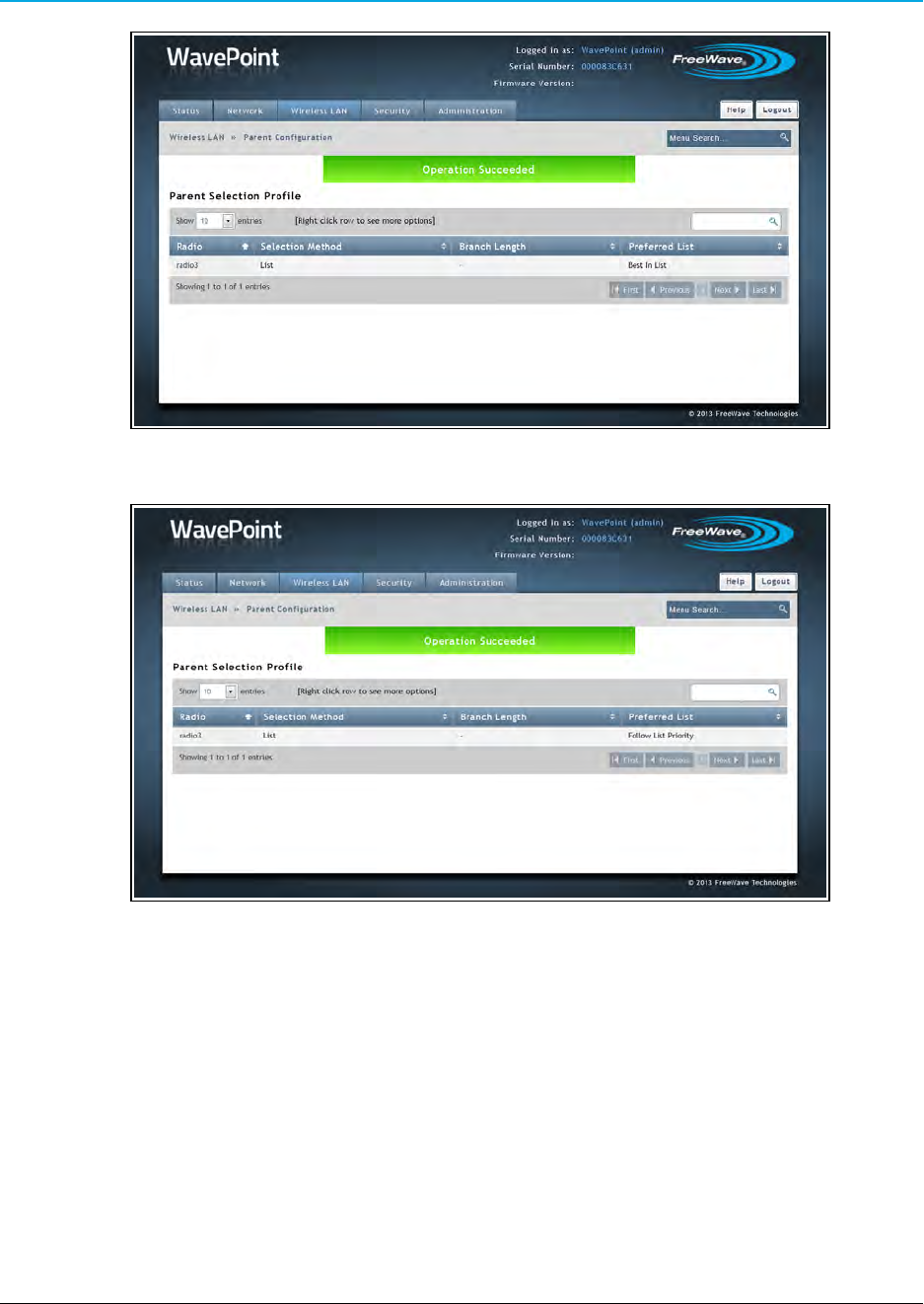
WavePoint 10e
Parent Selection Profile window with a successful Best in List WaveMesh
Parent Selection Profile window with a successful Follow List Priority WaveMesh
LUM0063AA Rev 05/05/2014 Page 77 of 171
This document is the property of FreeWave Technologies, Inc. and contains proprietary information owned by
FreeWave®. This document cannot be reproduced in whole or in part by any means without written permission from
FreeWave Technologies, Inc.

Page 78 of 171 LUM0063AA Rev 05/05/2014
This document is the property of FreeWave Technologies, Inc. and contains proprietary information owned by
FreeWave®. This document cannot be reproduced in whole or in part by any means without written permission from
FreeWave Technologies, Inc.

Chapter 4: Configuring Wireless Access
WavePoint 10e can provide connectivity between wired Ethernet networks and radio-equipped
wireless devices using Orthogonal Frequency Division Multiplexing (OFDM).
WavePoint 10e supports Point-to-Point (one-to-one communication link) wireless network types.
WavePoint 10e will support the following additional functionality in the next release:
lPoint-to-Multipoint - One-to-many communication link.
Example: An Access Point communicating with multiple Clients and
Repeaters.
This chapter provides information about:
lSetting up radios in network topographies.
lSecuring the wireless network from potentially malicious attacks.
lScheduling on and off times for an Access Point.
Example: Point-to-Point Configuration
Point-to-Point networks are networks that pass information from Point A to Point B.
In this example, data communication is directly between two points:
LUM0063AARev 05/05/2014 Page 79 of 171
This document is the property of FreeWave Technologies, Inc. and contains proprietary information owned by
FreeWave®. This document cannot be reproduced in whole or in part by any means without written permission from
FreeWave Technologies, Inc.
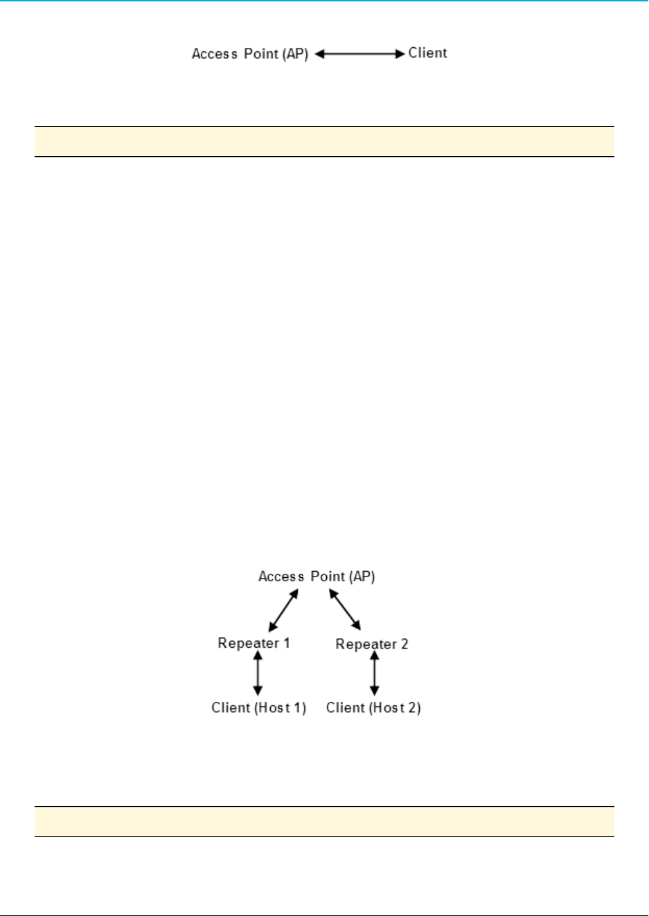
Chapter 4: Configuring Wireless Access
Configuring a Point-to-Point Network
Note: Both components communicate using a 2.4 GHz radio.
1. On the Wireless LAN > Radios > Basic page, set the AP to an Access Point.
2. Configure the wireless security settings described in Configuring Wireless
Communication on page 82.
3. On the Wireless LAN > Radios > Basic page, set the Client to Client mode.
4. Configure the wireless security settings to match the AP described in Configuring
Wireless Communication on page 82.
Point-to-Multipoint Configuration Examples
Multipoint networks can be in any number of configurations. This section provides two examples to
illustrate how to define the wireless settings on the WavePoint 10e Configuration pages.
Example 1: Point-to-Multipoint
In this example:
lData from Host 1 routes through Repeater 1 back to the Access Point (AP).
lData from Host 2 routes through Repeater 2 back to the AP.
Example 1: Point-to-Multipoint
Setup Procedure
Note: All components communicate using a 2.4 GHz radio.
Page 80 of 171 LUM0063AA Rev 05/05/2014
This document is the property of FreeWave Technologies, Inc. and contains proprietary information owned by
FreeWave®. This document cannot be reproduced in whole or in part by any means without written permission from
FreeWave Technologies, Inc.
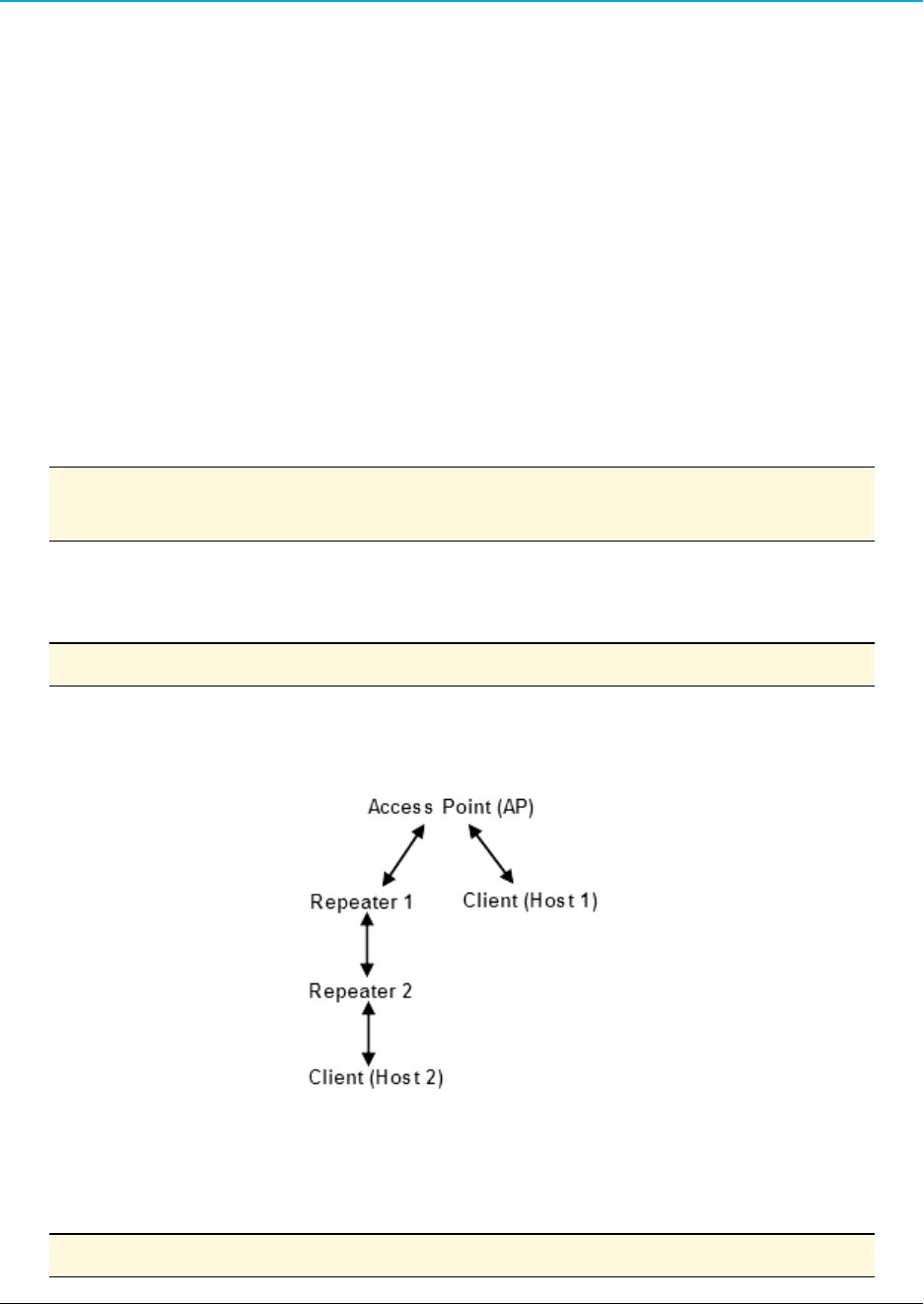
WavePoint 10e
1. On the Wireless LAN > Radios > Basic page, set the Access Point.
2. Configure the wireless security settings described in Configuring Wireless
Communication on page 82.
3. On the Wireless LAN > Radios > Basic page, set Repeater 1 and Repeater 2 to
Repeater mode.
4. Configure the wireless security settings to match the AP described in Configuring
Wireless Communication on page 82.
5. Set all components in the network to use the same Channel Width and Channel Size in
the Wireless LAN > Radios > Advanced page described in Defining Advanced Radio
Settings on page 85.
6. Verify the Max Distance parameter for each component is set to twice the distance (2x
Distance) between it and the device to which it connects.
Note: Additional advanced settings not described in this example may be required for the
network.
Example 2: Point-to-Multipoint
In this example:
Note: Repeater 2 must be set to find Repeater 1 for this type of wireless network.
lData from Host 1 routes directly to the AP.
lData from Host 2 routes through Repeater 2 and Repeater 1 back to the AP.
Example 2: Point-to-Multipoint
Procedure
Note: All components communicate using a 2.4 GHz radio.
LUM0063AA Rev 05/05/2014 Page 81 of 171
This document is the property of FreeWave Technologies, Inc. and contains proprietary information owned by
FreeWave®. This document cannot be reproduced in whole or in part by any means without written permission from
FreeWave Technologies, Inc.

Chapter 4: Configuring Wireless Access
1. On the Wireless LAN > Radios > Basic page, set the Access Point.
2. Configure the wireless security settings described in Configuring Wireless
Communication on page 82.
3. On the Wireless LAN > Radios > Basic page, set Repeater 1 and Repeater 2 to
Repeater mode.
4. Configure the wireless security settings to match the AP described in Configuring
Wireless Communication on page 82.
5. On the Wireless LAN > Radios > Advanced page, set all components in the network to
use the same Channel Width and Channel Size.
This is described in Defining Advanced Radio Settings on page 85.
6. Set the Max Distance parameter for each component to twice the distance (2x Distance)
between it and the device it connects to.
If the WaveMesh feature is activated, these optional selections can be made:
a. On the Wireless LAN > Parent Configuration page, set Repeater 1 to select its
parent (the AP) using the Branch selection method and a branch length of 1
(indicating a single hop).
b. On the Wireless LAN > Parent Configuration page, set Repeater 2 to select its
parent (Repeater 1) using the Branch selection method and a branch length of 2
(indicating 2 hops).
Configuring Wireless Communication
Each WavePoint 10e is configured with at least one radio for wireless communication. Using the
basic wireless settings, a WavePoint 10e can be configured as:
la wireless Access Point (AP) in the network that other wireless devices communicate with
that have the same 802.11 adapter settings and are within range.
la Repeater to extend the range of the network or as a Client at the ending point within the
network topology.
The basic instructions apply to all radio configurations, regardless of network topography.
Note: Verify the SSID, security method and security keys, channel, channel width, and
802.11 mode are set the same on all devices in a wireless network to establish a
link.
By default, all WavePoint 10e devices are shipped with the same SSID and
Security Key and will connect automatically.
Page 82 of 171 LUM0063AA Rev 05/05/2014
This document is the property of FreeWave Technologies, Inc. and contains proprietary information owned by
FreeWave®. This document cannot be reproduced in whole or in part by any means without written permission from
FreeWave Technologies, Inc.

WavePoint 10e
FreeWave Recommends: For security, and to avoid duplication of neighboring network names, it
is highly recommended that either the SSID or the Security Key be changed to a unique ID.
For information about defining and enabling virtual APs, see Enabling Virtual Access Points on page
89.
Procedure
1. Connect to the WavePoint 10e either through an Ethernet cable connected to Ethernet
port 3 or 4 or through the computer's wireless options.
2. Use a web browser to access the Configuration pages.
3. On the Wireless LAN menu, click Radios > Basic.
The Basic Radio table lists the available radios.
4. Right-click the radio in the table to configure and click Edit.
Radios are labeled 1, 2, 3, and 4.
The label on the back panel of each WavePoint 10e identifies what type of radio is
installed and which number corresponds to each installed radio.
5. In the Mode field, select the device's role in the network:
lAccess Point - Indicates this WavePoint 10e is the device in the wireless
network.
lMany network settings are provided to Repeaters and Clients from the AP.
lRepeater -Repeaters communicate with the AP, another Repeater, or a Client.
lThey are used to extend the physical distance of the network and allow wireless
clients to connect to wireless resources.
lClient - Clients communicate with Repeaters or the AP in the network.
lClients are the ending points in the network topography.
6. Enter this information that identifies the AP in the wireless network:
a. In the SSID field, enter a case sensitive, alphanumeric name that identifies this
device in a wireless access list.
Note: All devices that attempt to connect to this wireless network must have
the same SSID.
b. Optional: Enter the BSSID device's physical MAC address.
LUM0063AA Rev 05/05/2014 Page 83 of 171
This document is the property of FreeWave Technologies, Inc. and contains proprietary information owned by
FreeWave®. This document cannot be reproduced in whole or in part by any means without written permission from
FreeWave Technologies, Inc.

Chapter 4: Configuring Wireless Access
c. By default, the device is set to broadcast the wireless network name.
Broadcasting the name allows other wireless devices to see the device
automatically.
Set the Hide SSID option to Off to disable the broadcast.
Note: Other wireless devices can still connect; however, they do not
automatically see this device in their access lists.
7. In the Security field, select a security method for the wireless network:
lOpen - This method requires no authentication to connect to the wireless device
and provides no data encryption.
Note: This is the least secure option and is NOT recommended.
lWPA - This method uses the Temporal Key Integrity Protocol (TKIP) to connect to
the wireless device.
lThis security method generates a new 128-bit key for each packet the device
transmits.
lEnter the security password in the Security Key field.
Note: All other devices that access this device must use the key entered
here.
lWPA2 - This method uses CCMP, a strong AES encryption method, for securing
data over the network providing stronger security than WPA.
lEnter the security password in the Security Key field.
Note: All other devices that access this device must use the key entered
here.
lWPA2-Enterprise - This method is a type of WPA2 security, WPA2-Enterprise
uses an external RADIUS server to authenticate users.
Note: For more information about defining RADIUS settings, see Defining EAP
Authentication and External RADIUS Servers on page 95.
8. Optional: Set the AP Isolation field to Off to allow devices that connect to this
WavePoint 10e to connect with one another.
This setting applies only if the device is configured as the Access Point in the Mode field.
The default setting is On, devices can connect to this access point, but cannot connect
directly to other connected devices.
Page 84 of 171 LUM0063AA Rev 05/05/2014
This document is the property of FreeWave Technologies, Inc. and contains proprietary information owned by
FreeWave®. This document cannot be reproduced in whole or in part by any means without written permission from
FreeWave Technologies, Inc.

WavePoint 10e
9. Optional: In the Follow Schedules field, select a schedule from the list if schedules were
defined.
10. Click Save to save the changes or Cancel to clear any changes without saving.
11. On the Wireless LAN menu, click Radios > Advanced.
The Advanced Radio table lists the radios available in the device.
12. Right-click the radio to configure and click Edit.
13. Complete these fields described in Defining Advanced Radio Settings on page 85:
a. Mode (Modulation Scheme)
b. Channel
c. Channel Width
d. Distance
There are additional fields available in the Advanced Radio settings that
are not required for basic setup but that may be helpful.
14. Click Save to save the changes or Cancel to clear any changes without saving.
Defining Advanced Radio Settings
When initially setting up a WavePoint 10e for wireless communication, review the settings in the
Wireless LAN > Radios > Advanced page to ensure the parameters are set to meet the needs of
the network. The Channel and Channel Width fields should match across radios that
communicate in the network.
Procedure
1. Connect to the WavePoint 10e either through an Ethernet cable connected to Ethernet
port 3 or 4 or through the computer's wireless options.
2. Use a web browser to access the Configuration pages.
3. On the Wireless LAN menu, click Radios > Advanced.
4. Right-click the radio in the table to change and click Edit.
Radios are labeled 1, 2, 3, and 4.
The label on the back panel of each WavePoint 10e identifies what type of radio is
installed and which number corresponds to each installed radio.
LUM0063AA Rev 05/05/2014 Page 85 of 171
This document is the property of FreeWave Technologies, Inc. and contains proprietary information owned by
FreeWave®. This document cannot be reproduced in whole or in part by any means without written permission from
FreeWave Technologies, Inc.

Chapter 4: Configuring Wireless Access
5. In the Mode field, select the 802.11 Modulation Scheme to transmit packets from this
radio.
6. Complete these radio settings using the fields provided:
7. Select the frequency Channel the radio is set to broadcast and receive data on.
Select Auto to let the system determine the best channel within the
frequency band to use based on the environmental noise levels for the
available channels.
8. Select the Channel Width (spacing) setting for the radio.
The Channel Width is specific to 802.11n traffic.
9. In the Tx Antennas field, select the number of transmit antennas to use.
Note: If the WavePoint 10e in use does not support MIMO, set this field to 1to
indicate a single transmit antenna.
10. In the Rx Antennas field, select the number of transmit antennas to use.
Note: If the WavePoint 10e in use does not support MIMO, set this field to 1to
indicate a single transmit antenna.
11. In the Rate field, select the rate that governs the transmission speed the radio uses after a
wireless link is negotiated.
Note: The mode or modulation scheme and the number of transmit antennas in
use determine the available settings.
Setting the rate to Auto allows the WavePoint 10e to determine the optimal
rate to use based on environment conditions.
Notes
With WavePoint 10e:
l2.4 GHz & 5 GHz, when running 802.11n, can use a maximum of three antennas.
l900 MHz can use only one antenna with a second antenna configured for Diversity.
lIf the Tx Antenna field is set to 1or only a single antenna is detected, the 802.11n
MCS index values in the drop-down menu range from 0 to 7.
lIf the Tx Antenna field is set to 2, the 802.11n MCS index values in the drop-down
menu range from 0 to 15.
Page 86 of 171 LUM0063AA Rev 05/05/2014
This document is the property of FreeWave Technologies, Inc. and contains proprietary information owned by
FreeWave®. This document cannot be reproduced in whole or in part by any means without written permission from
FreeWave Technologies, Inc.

WavePoint 10e
lIf the Tx Antenna field is set to 3, the 802.11n MCS index values in the drop-down
menu range from 0 to 23.
12. Select the maximum Parent Rate to use when connecting to the upstream device
(Repeater or Access Point).
This parameter is applicable to the WavePoint 10e set as either a Repeater or Client.
Note: The available Parent Rate parameters are the same as in those available
in the Rate field.
13. Select the radio's Transmit Power in dBm, based on the radio's intrinsic power range.
When testing at a facility and devices are close in proximity to one another,
set the Transmit Power parameter to a low number.
When deploying the WavePoint 10e to the field, raise the Transmit Power
number accordingly.
14. Set the N only Mode option to On if legacy (802.11b or 802.11g) clients are NOT to
connect to this radio.
Selecting On ensures that the radio's bandwidth is only available for clients connecting at
802.11n rates.
15. Set the Enable AMSDU option to Off to optimize throughput for small sized data packets.
The 802.11n protocol uses this option to aggregate small size TCP packets.
Note: Small frames with the same physical source and destinations are combined
to a larger frame to improve overall throughput by cutting down transmission
overhead.
16. Use the Power Constraint field to limit the maximum power that an Access Point or
Repeater uses to communicate upstream.
The setting in this field does not change the transmit power for downstream
communications.
Example: Using this topography:
The Transmit Power in the Access Point and Repeater is set to 31 dBm and is
used for transmissions from the Access Point to the Repeater and from the
Repeater to the Client (endpoint).
The Repeater has a power constraint setting of 10 dBm, so transmission
LUM0063AA Rev 05/05/2014 Page 87 of 171
This document is the property of FreeWave Technologies, Inc. and contains proprietary information owned by
FreeWave®. This document cannot be reproduced in whole or in part by any means without written permission from
FreeWave Technologies, Inc.

Chapter 4: Configuring Wireless Access
upstream from the Repeater to the Access Point are reduced to 10 dBm.
This parameter is applicable only for radios set Access Point and Repeater
mode.
17. Enter the DTIM Interval that determines how often the Access Point sends notification of
the buffered data.
Note: A delivery traffic indication message (DTIM) is a map that informs
Repeaters and Clients about the presence of buffered multicast/broadcast
data on the Access Point waiting to be sent.
18. In the RTS Threshold field, enter the packet size in bytes that requires the WavePoint
10e to check the transmitting frames to determine if a Request to Send (RTS)/Clear to
Send (CTS) handshake is required with the receiving Client.
The default value is 2346, which effectively disables RTS.
Using a small value causes the device to send RTS packets more often,
consuming more of the available bandwidth; therefore, reducing the
apparent throughput of the network packets.
19. In the Max Range field, enter, in kilometers, the distance between this WavePoint 10e
and the farthest away device it is linking to.
The maximum is 2 times the distance (2x Distance).
20. Select the Country the WavePoint 10e is installed in.
21. Click Save to save the changes or Cancel to clear any changes without saving.
Verify the Wireless Connection
While the WavePoint 10e is easily accessible, verify that the wireless connection
is active.
Important: This procedure is only applicable to 2.4 GHz WavePoint™devices.
1. Log out of the Configuration web pages.
2. Close the web browser.
3. Disconnect the Ethernet cable from the computer.
4. Using a computer with wireless capability, establish a wireless connection using the SSID
and Security Key defined in the Basic Radio Settings page.
Page 88 of 171 LUM0063AA Rev 05/05/2014
This document is the property of FreeWave Technologies, Inc. and contains proprietary information owned by
FreeWave®. This document cannot be reproduced in whole or in part by any means without written permission from
FreeWave Technologies, Inc.

WavePoint 10e
5. After the connection is established, open a web browser and enter the IP address in the
browser navigation bar.
The IP address was entered in the LAN Setup page.
The Login page is shown when a successful wireless connection has been made.
If there is no connection, see the Internet Connection and Browser Display on page 147
Enabling Virtual Access Points
A Virtual Access Point (VAP) is similar to a VLAN, but in a wireless environment. VAPs are a way to
segment a wireless network so a single AP presents itself in the network as multiple APs.
Connecting wireless Repeaters or Clients see a VAP as a unique and independent AP while it is
actually a single, physical AP in the network.
Using VAPs offer these advantages:
lDiffering levels of security across the VAPs.
lIsolate portions of the wireless network.
A single WavePoint 10e can be used for multiple purposes, providing cost savings
and simplicity in designing the network.
Each radio in the WavePoint 10e can have a maximum of three VAPs enabled. Each VAP enabled
on a single radio uses the settings set for the radio in the Wireless LAN > Radios > Basic and
Wireless LAN > Radios > Advanced pages.
Note: Enabling VAPs can impact the overall throughput available for a radio.
Procedure
1. Connect to the WavePoint 10e either through an Ethernet cable connected to Ethernet
port 3 or 4 or through the computer's wireless options.
2. Use a web browser to access the Configuration pages.
3. On the Wireless LAN menu, click Virtual APs.
The table lists the available VAPs for each radio and their status.
4. Right-click a VAP in the list and click Enable.
LUM0063AA Rev 05/05/2014 Page 89 of 171
This document is the property of FreeWave Technologies, Inc. and contains proprietary information owned by
FreeWave®. This document cannot be reproduced in whole or in part by any means without written permission from
FreeWave Technologies, Inc.

Chapter 4: Configuring Wireless Access
Change a Virtual Access Point's Settings
1. Connect to the WavePoint 10e either through an Ethernet cable connected to Ethernet
port 3 or 4 or through the computer's wireless options.
2. Use a web browser to access the Configuration pages.
3. On the Wireless LAN menu, click Virtual APs.
The table lists the available VAPs for each radio and their status.
4. Right-click a VAP in the list and click Edit.
5. Enter a unique AP Name to identify the VAP.
Note: This name identifies the VAP on the Configuration pages, but is not
broadcast.
6. In the SSID field, enter a case sensitive, alphanumeric name that identifies this VAP in a
wireless access list.
A maximum of 32 characters are allowed.
Note: All devices that attempt to connect to this VAP must have the same SSID.
7. In the Security field, select a security method for the wireless network:
lOpen - This method requires no authentication to connect to the wireless device
and provides no data encryption.
Note: This is the least secure option and is NOT recommended.
lWPA - This method uses the Temporal Key Integrity Protocol (TKIP) to connect to
the wireless device.
lThis security method generates a new 128-bit key for each packet the device
transmits.
lEnter the security password in the Security Key field.
Important: All other devices that access this device must use the key
entered in the WPA field.
lWPA2 - This method uses CCMP, a strong AES encryption method, for securing
data over the network providing stronger security than WPA.
lEnter the security password in the Security Key field.
Important: All other devices that access this device must use the key
entered in the WPA2 field.
Page 90 of 171 LUM0063AA Rev 05/05/2014
This document is the property of FreeWave Technologies, Inc. and contains proprietary information owned by
FreeWave®. This document cannot be reproduced in whole or in part by any means without written permission from
FreeWave Technologies, Inc.

WavePoint 10e
lWPA2-Enterprise - This method is a type of WPA2 security, WPA2-Enterprise
uses an external RADIUS server to authenticate users.
Note: For more information about defining RADIUS settings, see Defining EAP
Authentication and External RADIUS Servers on page 95.
8. Optional: Set the AP Isolation field to Off to allow devices that connect to this VAP to be
able to connect with one another.
The default setting is On, which means that devices can connect to this VAP, but cannot
connect directly to other connected devices.
9. Click Save to save the changes or Cancel to clear any changes without saving.
Wireless Security
Enabling security filtering and user authentication are essential to secure the wireless data.
WavePoint 10e supports a variety of consumer and enterprise security, encryption, and
authentication options.
Authorizing Wireless Access
To increase the security of the wireless LAN, define a list of devices that have access based on their
MAC addresses. Filtering MAC addresses restricts which devices can access the network;
however, it does not secure the data broadcast over the wireless link.
Procedure
1. Connect to the WavePoint 10e either through an Ethernet cable connected to Ethernet
port 3 or 4 or through the computer's wireless options.
2. Use a web browser to access the Configuration pages.
3. On the Wireless LAN menu, click Authorized AP List.
The table shows MAC addresses already authorized for access.
4. Do one of the following:
lAdd - Click Add New Authorized AP below the Available Authorized AP table.
lDelete - Right-click an existing Authorized AP and click Delete.
lDelete All - Right-click anywhere in the table and click Select All > Delete.
4. In the SSID field, enter the network name of the device to authorize.
5. In the MAC Address field, enter the hardware address of the device to authorize.
LUM0063AA Rev 05/05/2014 Page 91 of 171
This document is the property of FreeWave Technologies, Inc. and contains proprietary information owned by
FreeWave®. This document cannot be reproduced in whole or in part by any means without written permission from
FreeWave Technologies, Inc.

Chapter 4: Configuring Wireless Access
6. In the Security field, select a security method for the wireless network:
lOpen - This method requires no authentication to connect to the wireless device
and provides no data encryption.
Note: This is the least secure option and is NOT recommended.
lWPA - This method uses the Temporal Key Integrity Protocol (TKIP) to connect to
the wireless device.
lThis security method generates a new 128-bit key for each packet the device
transmits.
lEnter the security password in the Security Key field.
Important: All other devices that access this device must use the key
entered in the WPA field.
lWPA2 - This method uses CCMP, a strong AES encryption method, for securing
data over the network providing stronger security than WPA.
lEnter the security password in the Security Key field.
Important: All other devices that access this device must use the key
entered in the WPA2 field.
lWPA2-Enterprise - This method is a type of WPA2 security, WPA2-Enterprise
uses an external RADIUS server to authenticate users.
Note: For more information about defining RADIUS settings, see Defining
EAP Authentication and External RADIUS Servers on page 95.
lEncryption - This method is available when either WPA or WPA2 is selected in
the Security field.
Select either the AES or TKIP method the device uses to access the network.
Note: The selected security method should match the security method defined in
the Wireless LAN > Radios > Basic menu.
7. ClickSave to save the changes and send them to the WavePoint 10e or click the Xin the
upper right corner to clear any changes without saving.
Restricting Access by MAC Address
To increase the security of the wireless network, restrict access to the network to only specific
devices based on their hardware address, or MAC address. Creating an Access Control List
Page 92 of 171 LUM0063AA Rev 05/05/2014
This document is the property of FreeWave Technologies, Inc. and contains proprietary information owned by
FreeWave®. This document cannot be reproduced in whole or in part by any means without written permission from
FreeWave Technologies, Inc.

WavePoint 10e
(ACL) of MAC addresses allows access to the network and adds security against devices that have
not been granted access to the network.
Important: The ACL does NOT secure the data that travels across the network..
Important: If configuring the WavePoint 10e through a wireless connection whose
MAC address is NOT in the ACL, the connection is lost when the changes are
saved.
This does include the laptop used to configure the WavePoint™device.
Use a wired connection or access from a computer whose address is in the ACL to
access the Configuration pages to make additional updates.
Set the ACL Policy Type
1. Connect to the WavePoint 10e either through an Ethernet cable connected to Ethernet
port 3 or 4 or through the computer's wireless options.
2. Use a web browser to access the Configuration pages.
3. On the Wireless LAN menu, click ACL.
4. Select a Policy Status:
lOpen - Allows any wireless device with any MAC address to connect to the
wireless network through the WavePoint 10e.
This is the default.
lAllow - Only permits MAC addresses in the List of MAC Addresses to connect to
the wireless network.
lDeny - Prevents any devices with a MAC addresses in the List of MAC Addresses
to connect to the wireless network.
5. Click Save to save the changes or Cancel to clear any changes without saving.
Add or Edit MAC Addresses in the ACL List
1. Connect to the WavePoint 10e either through an Ethernet cable connected to Ethernet
port 3 or 4 or through the computer's wireless options.
2. Use a web browser to access the Configuration pages.
3. On the Wireless LAN menu, click ACL.
4. Click Add New MAC Address under the List of MAC Addresses table.
LUM0063AA Rev 05/05/2014 Page 93 of 171
This document is the property of FreeWave Technologies, Inc. and contains proprietary information owned by
FreeWave®. This document cannot be reproduced in whole or in part by any means without written permission from
FreeWave Technologies, Inc.

Chapter 4: Configuring Wireless Access
5. In the MAC Address field, enter the MAC address of the device to grant network access
to.
Note: MAC addresses are typically printed on a device's physical label.
6. Click Save to save the changes or Cancel to clear any changes without saving.
Delete a Device from the List
lRight-click an address in the table and click Delete.
lRight-click anywhere in the table and click Select All > Delete.
Enabling Rogue Access Point Detection
A rogue access point is any device that accesses the network without authorization. Rogue access
points often do not meet the wireless LAN security policies and can allow anyone with a wireless-
enabled device to connect to the network.
Enabling rogue detection identifies unauthorized wireless devices and prevents them from
accessing the wireless network. WavePoint 10e collects a list of unauthorized devices that
attempted to access the network for review.
Procedure
1. Connect to the WavePoint 10e either through an Ethernet cable connected to Ethernet
port 3 or 4 or through the computer's wireless options.
2. Use a web browser to access the Configuration pages.
3. On the Wireless LAN menu, click Rogue AP List.
4. In the Radio field, select the radio to enable rogue detection on.
Radios are labeled 1, 2, 3, and 4.
The label on the back panel of each WavePoint 10e identifies what type of radio is
installed and which number corresponds to each installed radio.
5. Set the Enable Rogue AP Detection option to On to enable rogue detection for the
selected radio.
6. Click Save to save the changes or Cancel to clear any changes without saving.
Review Devices that Attempted to Access the Network
1. Connect to the WavePoint 10e either through an Ethernet cable connected to Ethernet
port 3 or 4 or through the computer's wireless options.
Page 94 of 171 LUM0063AA Rev 05/05/2014
This document is the property of FreeWave Technologies, Inc. and contains proprietary information owned by
FreeWave®. This document cannot be reproduced in whole or in part by any means without written permission from
FreeWave Technologies, Inc.

WavePoint 10e
2. Use a web browser to access the Configuration pages.
3. On the Wireless LAN menu, click Rogue AP List.
The Rogue AP List at the bottom of the page identifies the:
lSSID and MAC address of the unauthorized devices that attempted to access the
wireless network.
lSecurity mode set on the rogue device.
lTime that has passed since the access attempt.
Defining EAP Authentication and External RADIUS Servers
In wireless communications using the Extensible Authentication Protocol (EAP), users request
connection to the wireless network through a WavePoint 10e. The WavePoint 10e then requests
the user's identity and sends that identity to the RADIUS authentication server.
If WPA-Enterprise is selected as the wireless security option in the Wireless LAN > Radios >
Basic menu, a RADIUS server must be defined to authenticate and authorize users and devices to
access the wireless network.
Note: A RADIUS server is an external server that provides authentication for devices
and users trying to access the wireless network.
Configure the EAP Authentication
1. Connect to the WavePoint 10e either through an Ethernet cable connected to Ethernet
port 3 or 4 or through the computer's wireless options.
2. Use a web browser to access the Configuration pages.
3. On the Wireless LAN menu, click RADIUS Settings.
4. In the EAP Authentication Configuration section, complete these fields:
a. Select the Outer EAP Method authentication used to establish a tunnel the User
Name and Password are exchanged over.
b. Enter the unique User Name for the user.
c. Enter the unencrypted Anonymous ID that a Client must match to start an
authentication request.
Note: Both EAP-TTLS and EAP-PEAP support anonymous identification,
or identification hiding.
An access point typically generates an EAP-Identity request used to
LUM0063AA Rev 05/05/2014 Page 95 of 171
This document is the property of FreeWave Technologies, Inc. and contains proprietary information owned by
FreeWave®. This document cannot be reproduced in whole or in part by any means without written permission from
FreeWave Technologies, Inc.

Chapter 4: Configuring Wireless Access
establish authentication and a connection.
A Client may respond with only enough information so the RADIUS
server can process the request.
d. Enter the unique Password a requester must send in an authentication request.
Note: The password can contain alphanumeric characters, underscores
(_), and dashes (-).
e. Select the Inner Authentication method to establish a second layer of authorizing
a client after the initial tunnel is established.
f. Enter the EAP Server Name or IP address of the configured security server.
5. Click Save to save the changes or Cancel to clear any changes without saving.
Define an External RADIUS Server
1. Connect to the WavePoint 10e either through an Ethernet cable connected to Ethernet
port 3 or 4 or through the computer's wireless options.
2. Use a web browser to access the Configuration pages.
3. On the Wireless LAN menu, click RADIUS Settings.
The current list of RADIUS servers are in the Radius Server section.
4. Right-click the server name in the table and click Edit.
5. Enter the Server IP address on the network where the authentication server is located.
6. Enter the Port number the external server uses.
7. Enter the Secret shared key the Access Point and the RADIUS server exchange during
an authentication attempt.
8. Enter the Timeout, in seconds, authentication attempt is timed out after no response from
the server.
9. In the Retries field, enter the number of times authentication with this server is attempted
on event of server timeout.
After this number of retry attempts fail, the authentication attempt is considered to have
failed.
10. Click Save to save the changes or Cancel to clear any changes without saving.
Page 96 of 171 LUM0063AA Rev 05/05/2014
This document is the property of FreeWave Technologies, Inc. and contains proprietary information owned by
FreeWave®. This document cannot be reproduced in whole or in part by any means without written permission from
FreeWave Technologies, Inc.

WavePoint 10e
Scheduling When Wireless Connections are Available
The WavePoint 10e deployment may not require a wireless network connection to be available 24
hours a day.
If the wireless access is only required during certain portions of the day, define the hours in the day
the wireless network is available for use.
This also helps to conserve power.
Note: The defined schedules apply to every day of the week.
Schedules for individual days cannot be defined.
Define and Enable a Schedule for a Wireless Connection
1. Connect to the WavePoint 10e either through an Ethernet cable connected to Ethernet
port 3 or 4 or through the computer's wireless options.
2. Use a web browser to access the Configuration pages.
3. On the Wireless LAN menu, click Wireless LAN Schedules.
The SSIDs, including Virtual APs, are shown in the table.
4. Right-click the SSID to define a schedule for and click Edit.
5. Set the Active option to On.
6. Use the HH,MM, and AM/PM dials to set the range of time the SSID is available.
7. Place the mouse cursor over a single dial and use the mouse roller to move the correct
number across the black line in the dial.
Example: Select 7:00 AM in the Start Time field and 7:00 PM in the End Time
field, the wireless network is only accessible from 7:00 AM to 7:00 PM each day.
8. Click Save to save the changes or Cancel to clear any changes without saving.
The schedule is updated in the table as Enabled.
LUM0063AA Rev 05/05/2014 Page 97 of 171
This document is the property of FreeWave Technologies, Inc. and contains proprietary information owned by
FreeWave®. This document cannot be reproduced in whole or in part by any means without written permission from
FreeWave Technologies, Inc.

Chapter 4: Configuring Wireless Access
Disable a Schedule
1. Connect to the WavePoint 10e either through an Ethernet cable connected to Ethernet
port 3 or 4 or through the computer's wireless options.
2. Use a web browser to access the Configuration pages.
3. On the Wireless LAN menu, click Wireless LAN Schedules.
The SSIDs, including Virtual APs, are shown in the table as Enabled.
4. In the schedule, right-click the SSID to disable.
5. Set the Active option to Off.
6. Click Save to save the changes or Cancel to clear any changes without saving.
Page 98 of 171 LUM0063AA Rev 05/05/2014
This document is the property of FreeWave Technologies, Inc. and contains proprietary information owned by
FreeWave®. This document cannot be reproduced in whole or in part by any means without written permission from
FreeWave Technologies, Inc.

Chapter 5: Security
This chapter discusses these options for securing the traffic in the network:
lFirewall setup including policies, rules, and scheduling.
lRADIUS server setup.
Firewall Overview
Inbound rules govern access from the WAN to the LAN. Using firewall rules allows only specified
local resources to be accessed from the Internet.
By default, all access from the Internet is blocked from accessing the secure LAN, except in
response to requests from the LAN. Outbound (LAN to WAN) rules restrict access to traffic leaving
the network, selectively allowing only specific local users to access outside resources.
Firewall Basic Policies
Default Outbound Policy
This configuration determines whether LAN users can access the Internet in the absence of specific
allowed outbound rules.
Use Allow Always as the default outbound policy to permit any outbound traffic to
pass through the firewall and reach the WAN.
LUM0063AARev 05/05/2014 Page 99 of 171
This document is the property of FreeWave Technologies, Inc. and contains proprietary information owned by
FreeWave®. This document cannot be reproduced in whole or in part by any means without written permission from
FreeWave Technologies, Inc.

Chapter 5: Security
Set the Outbound Traffic Policy
1. Connect to the WavePoint 10e either through an Ethernet cable connected to Ethernet
port 3 or 4 or through the computer's wireless options.
2. Use a web browser to access the Configuration pages.
3. On the Security menu, click Firewall > Basic Policies.
The Basic Policies screen opens.
4. Select an option:
lAllow Always permits any outbound traffic to pass through the firewall and reach
the WAN.
lBlock Always closely manages the outbound traffic.
lThe Network Administrator must configure firewall and application rules to
permit outbound traffic from LAN addresses
5. Click Save to save the changes or Cancel to clear any changes without saving.
Note: Verify the IPv6 features are enabled in the Network > IPv6 menu to set the
outbound policy for IPv6 networks.
Firewall Rules
Creating Firewall Rules for IPv4
1. Connect to the WavePoint 10e either through an Ethernet cable connected to Ethernet
port 3 or 4 or through the computer's wireless options.
2. Use a web browser to access the Configuration pages.
3. On the Security menu, click Firewall > IPv4 Firewall Rules.
The IPv4 firewall rules are listed in the table.
4. Do one of the following:
lEdit an existing IPv4 Firewall Rule - Right-click an existing Firewall Rule and
select Edit.
lAdd a new IPv4 Firewall Rule - Click IPv4 Add Firewall Rule below the
Available IPv4 Firewall Rules table
5. In the From Zone, enter the source of the traffic this firewall rule controls.
lSecure (LAN) - Select this option if the traffic is coming from a secure location
(from the LAN).
Page 100 of 171 LUM0063AA Rev 05/05/2014
This document is the property of FreeWave Technologies, Inc. and contains proprietary information owned by
FreeWave®. This document cannot be reproduced in whole or in part by any means without written permission from
FreeWave Technologies, Inc.

WavePoint 10e
lInsecure (WAN) - Select this option if the traffic is coming from a non-secure
location (from the WAN).
6. In the To Zone, enter the destination of the traffic this firewall rule controls.
Note: Traffic can only be sent to a secure location.
7. Select a Service option from the drop down list or add an additional service on Firewall >
Custom Services.
The name usually indicates the type of traffic the rule covers (e.g., FTP, SSH, telnet, ping,
etc.).
8. Select an Action to be taken on the enabled rule:
lAlways Block - Blocks the selected service all the time.
lAlways Allow - Allows the selected service all the time.
lBlock by schedule , otherwise Allow - Allow block access in conjunction with a
defined schedule in the Schedule Configuration page.
lAllow by schedule, otherwise block - Allow access in conjunction with a defined
schedule in the Schedule Configuration page.
9. Select a Source Hosts that originates the traffic for this firewall rule:
lAny - The rule applies to all traffic from all hosts.
lSingle - The rule applies to traffic from a single host.
Enter the IP address of the host in the From field.
lRange - The rule applies to traffic from a group of computers/devices within an IP
address range.
Enter the first IP address in the From field and enter the final IP address in the To
field.
10. Select a Destination Hosts that receives the traffic for this firewall rule:
lAny - The rule applies to traffic destined to all hosts.
lSingle - The rule applies to traffic destined for a single host.
Enter the IP address of the host in the From field.
lRange - The rule applies to traffic destined for a group of computers/devices within
an IP address range.
Enter the first IP address in the From field and enter the final IP address in the To
field.
11. In the Log field, select the Never option button to disable logging.
12. In the QoS Priority field, select one Type of Service option.
This is the priority of the IP packets assigned for this service.
LUM0063AA Rev 05/05/2014 Page 101 of 171
This document is the property of FreeWave Technologies, Inc. and contains proprietary information owned by
FreeWave®. This document cannot be reproduced in whole or in part by any means without written permission from
FreeWave Technologies, Inc.

Chapter 5: Security
Note: The priorities are defined by Type of Service (TOS) in the Internet Protocol
Suite standards, RFC 1349.
Service Type ToS Description
Normal Service 0 (zero) No special priority is given to the traffic.
Minimize Cost 2 Transfer of data over a link that has a lower cost.
Maximize Reliability 4 Transfer of data over a more reliable link with little or no
transmission.
Maximize Throughput 8
Enables the importance of a high volume of data to be
transferred during an interval even if the latency over the
link is high.
Minimize Delay 16 Enables low latency for the packet to reach the
destination.
13. In the Select Schedule field, select the applicable schedule.
This field is visible when a selection is made in the Action field.
14. In the Internal IP Address field, enter an IP address of the computer on the LAN hosting
the server.
This field is visible in the Destination NAT Settings section when the source of the
traffic this firewall rule controls is set to INSECURE (WAN) in the From Zone field.
15. Set the Enable Port Forwarding field to On to forward to the port specified in the
Translate Port Number field.
This field is visible in the Destination NAT Settings section when the source of the traffic
this firewall rule controls is set to INSECURE (WAN) in the From Zone field.
16. In the Translate Port Number field, enter the port number to use for port forwarding.
This field is visible in the Destination NAT Settings section when the source of the traffic
this firewall rule controls is set to INSECURE (WAN) in the From Zone field.
Example: If a computer on the local network side is running a telnet server on
port 2000, then set the Enable Port Forwarding option to On and enter 2000 in
the Translate Port Number field.
If the server is listening on the default port 23, then it could be disabled.
17. In the External IP Address field, select the internet destination IP address used for this
firewall rule: WAN1, WAN2, or Other.
This field is visible in the Destination NAT Settings section when the source of the traffic
this firewall rule controls is set to INSECURE (WAN) in the From Zone field.
Page 102 of 171 LUM0063AA Rev 05/05/2014
This document is the property of FreeWave Technologies, Inc. and contains proprietary information owned by
FreeWave®. This document cannot be reproduced in whole or in part by any means without written permission from
FreeWave Technologies, Inc.

WavePoint 10e
Note: If Other is selected, enter the IP address in the Other IP address field.
18. Click Save to save the changes or Cancel to clear any changes without saving.
Delete an IPv4 Firewall Rule
1. Connect to the WavePoint 10e either through an Ethernet cable connected to Ethernet
port 3 or 4 or through the computer's wireless options.
2. Use a web browser to access the Configuration pages.
3. On the Security menu, click Firewall > IPv4 Firewall Rules.
The defined IPv4 firewall rules are listed in the table.
4. Right click the IPv4 firewall rule to remove and click Delete.
Note: Right-click anywhere in the table and click Select All > Delete to delete all
the IPv4 firewall rules.
5. Click Save to save the changes or Cancel to clear any changes without saving.
Disable an IPv4 Firewall Rule
1. Connect to the WavePoint 10e either through an Ethernet cable connected to Ethernet
port 3 or 4 or through the computer's wireless options.
2. Use a web browser to access the Configuration pages.
3. On the Security menu, click Firewall > IPv4 Firewall Rules.
The defined IPv4 firewall rules are listed in the table.
4. Right-click the IPv4 firewall rule to turn off and click Disable.
Note: Right-click anywhere in the table and click Select All > Disable to disable
all the IPv4 firewall rules
5. Click Save to save the changes or Cancel to clear any changes without saving.
Custom Services
While common services use known TCP/UDP/TCP and UDP/ICMP/ICMPv6 ports, many custom or
uncommon applications require traffic to be sent through the firewall. The parameters in this section
allow the traffic type and static ports to be defined for a unique identifier and then create firewall rules
for the user-defined service.
LUM0063AA Rev 05/05/2014 Page 103 of 171
This document is the property of FreeWave Technologies, Inc. and contains proprietary information owned by
FreeWave®. This document cannot be reproduced in whole or in part by any means without written permission from
FreeWave Technologies, Inc.

Chapter 5: Security
Configure Custom Service Settings
1. Connect to the WavePoint 10e either through an Ethernet cable connected to Ethernet
port 3 or 4 or through the computer's wireless options.
2. Use a web browser to access the Configuration pages.
3. On the Security menu, click Firewall > Custom Services.
The list of defined custom services is shown.
4. Do one of the following:
lEdit an existing Custom Service - Right-click an existing Custom Service and
click Edit.
lAdd a new Custom Service - Click Add New Custom Service below the
Available Custom Services table.
5. Enter the Name of the service for identification and management purposes.
6. Select a Type option the layer 3 (network layer) protocol that the service uses.
7. In the ICMP Type field, enter the numeric value ranging between 0 and 40 for ICMP or
ranging between 1 and 255 for ICMPv6.
This field is visible when the layer 3 protocol (in the Type field) is selected as ICMP or
ICMPv6.
8. In the Port Type field, select whether the service covers a range of ports or multiple ports
not in a range.
9. In the Start Port field, enter the first TCP, UDP, or TCP and UDP port in a range or ports
that the service uses.
If the service uses only one port, enter the same port in the End Port and Start Port
fields.
10. In the End Port field, enter the last port in the range of ports that the service uses.
If the service uses only one port, enter the same port in the End Port and Start Port
fields.
11. Enter the Ports this service supports separated by commas (,).
This field is visible when the Multiple Ports option button is selected.
12. Click Save to save the changes or Cancel to clear any changes without saving.
Delete an Existing Custom Service
1. Connect to the WavePoint 10e either through an Ethernet cable connected to Ethernet
port 3 or 4 or through the computer's wireless options.
2. Use a web browser to access the Configuration pages.
Page 104 of 171 LUM0063AA Rev 05/05/2014
This document is the property of FreeWave Technologies, Inc. and contains proprietary information owned by
FreeWave®. This document cannot be reproduced in whole or in part by any means without written permission from
FreeWave Technologies, Inc.

WavePoint 10e
3. On the Security menu, click Firewall > Custom Services.
The defined custom services are listed in the table.
4. Right click the custom service to remove and click Delete.
Note: Right-click anywhere in the table and click Select All > Delete to delete all
the custom services.
5. Click Save to save the changes or Cancel to clear any changes without saving.
VPN Passthrough
Configure the device's firewall settings to allow outbound encrypted VPN traffic for IPsec, PPTP,
and L2TP VPN tunnel connections. Enable the LAN-to-WAN pass through support on this page as
compared to creating a service-specific firewall outbound policy.
Procedure
1. Connect to the WavePoint 10e either through an Ethernet cable connected to Ethernet
port 3 or 4 or through the computer's wireless options.
2. Use a web browser to access the Configuration pages.
3. On the Security menu, click Firewall > VPN Passthrough.
The VPN Passthrough Setup page opens.
4. Set the IP Sec field to On to enable IPsec tunnels to pass through.
5. Set the PPTP to On to enable PPTP tunnels to pass through.
6. Set the L2TP to On to enable L2TP tunnels to pass through.
7. Click Save to save the changes or Cancel to clear any changes without saving.
Firewall Schedules
Schedules allow firewall rules to be enabled or disabled based on the time of day or day of the week.
Defined schedules are available to select in the Firewall Rule Configuration page.
Note: All schedules follow the time in the device's defined time zone.
Configuring Firewall Schedules
1. Connect to the WavePoint 10e either through an Ethernet cable connected to Ethernet
port 3 or 4 or through the computer's wireless options.
2. Use a web browser to access the Configuration pages.
3. On the Security menu, click Firewall > Firewall Schedules.
The defined Firewall Schedules are listed in the table.
LUM0063AA Rev 05/05/2014 Page 105 of 171
This document is the property of FreeWave Technologies, Inc. and contains proprietary information owned by
FreeWave®. This document cannot be reproduced in whole or in part by any means without written permission from
FreeWave Technologies, Inc.

Chapter 5: Security
4. Do one of the following:
lEdit an existing Firewall Schedule - Right-click an existing Firewall Schedule
and click Edit.
lAdd a new Firewall Schedule - Click Add New Schedule below the Available
Firewall Schedules table.
5. Enter a Name to identify the schedule.
The name is shown on the Firewall Rules Configuration page.
6. Set one or more of the Days to On to apply the schedule to the selected days.
7. In the Time of Day field, select the Specific Times radio button to specify during what
time period the schedule will apply.
8. Use the HH,MM, and AM/PM dials to set the schedule Start Time.
This field is visible when the Specific Times radio button is selected.
Note: Place the cursor over a single dial and use the mouse roller to move the
correct number across the black line in the dial.
The selected time populates in the Start Time field.
9. Use the HH,MM, and AM/PM dials to set the schedule End Time.
This field is visible when the Specific Times radio button is selected.
Note: Place the cursor over a single dial and use the mouse roller to move the
correct number across the black line in the dial.
The selected time populates in the End Time field.
10. Click Save to save the changes or Cancel to clear any changes without saving.
Delete a Firewall Schedule
1. Connect to the WavePoint 10e either through an Ethernet cable connected to Ethernet
port 3 or 4 or through the computer's wireless options.
2. Use a web browser to access the Configuration pages.
3. On the Security menu, click Firewall > Firewall Schedules.
The defined Firewall Schedules are listed in the table.
4. Right-click the firewall schedule to remove and click Delete.
Note: Right-click anywhere in the table and click Select All > Delete to delete all
the firewall schedules.
5. Click Save to save the changes or Cancel to clear any changes without saving.
Page 106 of 171 LUM0063AA Rev 05/05/2014
This document is the property of FreeWave Technologies, Inc. and contains proprietary information owned by
FreeWave®. This document cannot be reproduced in whole or in part by any means without written permission from
FreeWave Technologies, Inc.

WavePoint 10e
Application Rules
Application rules are commonly referred to as port triggering rules. Port triggering allows computers
on the LAN to request one or more ports to be forwarded to them.
Port triggering waits for an outbound request from the private network on one of the defined
outgoing ports. It automatically sets up forwarding to the IP address the request was made from.
When the application stops transmitting data over the port, the device waits for a timeout interval and
then closes the port or range of ports, making them available to other computers on the LAN.
Example: If an IRC client on the private network makes a connection request through
port 6667 and sends its Username information to the IRC server.
The IRC server sends an IDENT verification packet on port 113 to check the authenticity
of the IRC client.
In NAT mode, the device discards this packet since it does not know which computer to
send the request on port 113 to.
A port triggering rule can define port 6667 (or the range: 6660 to 7000) as the outgoing
(trigger) ports and port 113 as the incoming (response) port.
Configuring Application Rules
1. Connect to the WavePoint 10e either through an Ethernet cable connected to Ethernet
port 3 or 4 or through the computer's wireless options.
2. Use a web browser to access the Configuration pages.
3. On the Security menu, click Firewall > Application Rules.
The Application Rules table is shown.
4. Do one of the following:
lEdit an existing Application Rule - Right-click an existing Application Rule
and click Edit.
lAdd a new Application Rule - Click Add New Application Rule below the
Available Application Rules table.
5. Enter a unique Name to identify the Application Rule.
6. Set the Enable option to On to activate the application rule.
7. Use the Protocol field to select whether the port uses the TCP or UDP.
8. Select the Interface name on which the port triggering rule is configured.
9. In the Outgoing (Trigger) Port Range Start and To fields, enter the port number or
range of port numbers that trigger this rule when a connection request from outgoing
traffic is made.
LUM0063AA Rev 05/05/2014 Page 107 of 171
This document is the property of FreeWave Technologies, Inc. and contains proprietary information owned by
FreeWave®. This document cannot be reproduced in whole or in part by any means without written permission from
FreeWave Technologies, Inc.

Chapter 5: Security
lThis is the port number or port number range the remote system uses to respond to
the request it receives.
lIf the outgoing connection uses only one port, then:
lboth the Start Port and End Port fields are the same port number.
lspecify the same port number in both fields.
10. In the Incoming (Response) Port Range Start and To fields, enter the port number or
range of port numbers that trigger this rule when a connection request from incoming
traffic is made.
lThis is the port number or port number range the remote system uses to respond to
the request it receives.
lIf the incoming connection uses only one port, then:
lboth the Start Port and End Port fields are the same port number.
lspecify the same port number in both fields.
11. Click Save to save the changes or Cancel to clear any changes without saving.
Delete an Application Rule
1. Connect to the WavePoint 10e either through an Ethernet cable connected to Ethernet
port 3 or 4 or through the computer's wireless options.
2. Use a web browser to access the Configuration pages.
3. On the Security menu, click Firewall > Application Rules.
The defined application rules are listed in the table
4. Right-click the application rules to remove and click Delete.
Note: Right-click anywhere in the table and click Select All > Delete to delete all
the application rules.
5. Click Save to save the changes or Cancel to clear any changes without saving.
Application Rules Status
The Application Rules Status page provides information about the traffic related to the currently
defined application rules. This information is available:
lIP Address: The internal network IP address that triggered the application rule to be
active, and resulted in response ports being opened.
lOpen Ports: The incoming response ports that have been opened through this firewall
based on the internal devices request.
Page 108 of 171 LUM0063AA Rev 05/05/2014
This document is the property of FreeWave Technologies, Inc. and contains proprietary information owned by
FreeWave®. This document cannot be reproduced in whole or in part by any means without written permission from
FreeWave Technologies, Inc.

WavePoint 10e
lTime Remaining (sec): The remaining time in seconds the open ports allows external
traffic. This time is reset whenever traffic is sent from the LAN out on the trigger ports.
VPN Tunnels and IPsec
VPNs allow the exchange of data across the Internet through a tunnel including the security and
policies defined in a private network. Using IP Security (IPsec), a dedicated connection with
encryption is enabled across the Internet to the network between:
lTwo Gateways
lFrom a Client to a Gateway
Configuring a VPN Tunnel with IPsec
Use the IPsec Configuration page to define a VPN tunnel for a Gateway connection or for remote
users who access the network with VPN client software.
The IPsec Configuration page simplifies creation of VPN tunnels by setting the VPNC (VPN
Consortium) recommended defaults. The VPN (IKE phase 1 and phase 2) parameters chosen by
the IPsec Configuration are based on the VPN Consortium's (VPNC) recommendations.
Note: More information about the VPNC recommendations can be found at
www.vpnc.org/vpn-standards.
Configuring a Basic VPN Tunnel
1. Connect to the WavePoint 10e either through an Ethernet cable connected to Ethernet
port 3 or 4 or through the computer's wireless options.
2. Use a web browser to access the Configuration pages.
3. On the Security menu, click VPN > IPsec Configuration.
4. Enter a Name for the connection for management purposes.
5. In the Select VPN Type field, select a tunnel type:
lSite-to-Site - Create a Gateway tunnel to another VPN Gateway.
lRemote Access - Create a tunnel to the WavePoint 10e for remote access.
6. Enter the Pre-Shared Key, between 8 and 49 characters, that is shared between devices
for authentication.
Important: This key must be entered exactly the same here and on the
remote VPN Gateway or Client.
LUM0063AA Rev 05/05/2014 Page 109 of 171
This document is the property of FreeWave Technologies, Inc. and contains proprietary information owned by
FreeWave®. This document cannot be reproduced in whole or in part by any means without written permission from
FreeWave Technologies, Inc.

Chapter 5: Security
7. Select a Remote Gateway Type to identify the remote Gateway by IP address or FQDN
(Fully Qualified Domain Name).
8. In the Remote WAN IP Address / FQDN field, enter the IP address or the Internet name
of the Gateway selected in the Remote Gateway Type field.
Note: The Internet name is defined as the FQDN, such as vpn.FreeWave.com.
9. Use the Local Gateway Type field to select how to identify the local Gateway.
10. In the Local WAN IP Address / FQDN field, enter the IP address or the Internet name of
the WAN interface of the Gateway selected in the Local Gateway Type field.
Leave this field blank to use the same FQDN or IP address that is specified
in the WAN configuration.
11. Enter the Remote LAN IP Address of the default IP address of the core network.
12. Enter the associated Remote LAN Subnet Mask for the remote LAN IP address.
Note: This information is only applicable for IPv4 networks.
13. Enter the Local LAN IP Address of the local LAN.
14. Enter the associated Local LAN Subnet Mask for the local LAN IP address.
Note: This information is only applicable for IPv4 networks.
15. Click Save to save the changes or Cancel to clear any changes without saving.
IPsec Policies
When setting up a manual policy, only the Phase 1 (Manual Policy) parameters are required to
define the encryption and authentication key details. These parameters must be the same as on the
remote peer. An auto IPsec policy uses IKE to automatically exchange keys between two IPsec
hosts. The Phase 1 (IKE) and Phase 2 (Auto Policy) details determine the tunnel security.
The IPsec policy can be in Tunnel or Transport mode.
lSelect Tunnel mode to pass traffic between two trusted networks through an untrusted
network.
lAccept the default Transport mode for end-to-end communication.
Note: The VPN parameters chosen by the IPsec Configuration are based on the VPN
Consortium's (VPNC) recommendations.
More information on the VPNC recommendations can be found at:
www.vpnc.org/vpn-standards.
Page 110 of 171 LUM0063AA Rev 05/05/2014
This document is the property of FreeWave Technologies, Inc. and contains proprietary information owned by
FreeWave®. This document cannot be reproduced in whole or in part by any means without written permission from
FreeWave Technologies, Inc.

WavePoint 10e
Configuring an IPsec VPN Policy
1. Connect to the WavePoint 10e either through an Ethernet cable connected to Ethernet
port 3 or 4 or through the computer's wireless options.
2. Use a web browser to access the Configuration pages.
3. On the Security menu, click VPN > IPsec Policies.
The IPsec VPN Policies table is shown.
4. Do one of the following:
lEdit an existing IPsec VPN Policy - Right-click an existing IPsec VPN Policy
and click Edit.
lAdd a new IPsec VPN Policy - Click Add New IPsec Policy below the
Available IPsec VPN Policies table.
5. Enter a Policy Name.
6. Select one Policy Type:
lAuto Policy – Some parameters for the VPN tunnel are generated automatically.
Selecting Auto Policy requires that you use the IKE (Internet Key Exchange)
protocol to perform negotiations between the two VPN Clients.
lManual Policy – All settings (including the keys) for the VPN tunnel are manually
entered for each Client. No third-party server or organization is involved.
7. Select either an IPv4 or IPv6 IP Protocol Version .
8. Select an IKE Version:
Note: This field is visible when Auto Policy is selected in the Policy Type field.
lIKEv1
lIKEv2 – Reduces bandwidth requirements and includes EAP authentication.
9. In the IPsec Mode select either:
lTunnel – if IPsec communication is required between two gateways AND the LAN
hosts of the Gateway.
Select this option to specify subnet, range, etc.
lTransport – secure communication is required between two Gateways.
lThe communication between only those two Gateways is secured.
lSubnet, range, etc. options for this mode cannot be made.
LUM0063AA Rev 05/05/2014 Page 111 of 171
This document is the property of FreeWave Technologies, Inc. and contains proprietary information owned by
FreeWave®. This document cannot be reproduced in whole or in part by any means without written permission from
FreeWave Technologies, Inc.

Chapter 5: Security
10. If two WAN ports are configured to connect to an ISP, use the Select Local Gateway to
select the Gateway used as the local Endpoint for this IPsec tunnel.
11. Select one option to identify the Remote Endpoint (IP) Gateway:
lIP Address – Enter the IP Address of the Gateway in the IP Address/FQDN
field.
lFQDN (Fully Qualified Domain Name) – Enter the IP Address of the FQDN in the
IP Address/FQDN field.
12. Set the Enable Mode Config field to On to enable the Mode Configuration feature.
Mode configuration is similar to DHCP and is used to assign IP addresses to remote VPN
clients.
13. Set the Enable NetBIOS option to Off to disable NetBIOS broadcasts over the VPN
tunnel.
When enabled, NetBIOS broadcasts are allowed to travel over the VPN tunnel.
Note: This field is visible when the IPsec Mode is set to Tunnel Mode.
14. Set the Enable Rollover to On to allow rollover of the VPN when WAN Mode is set to
Auto Rollover on the Network > WAN Mode page.
15. In the Protocol field, select either:
lAH – Guarantees connectionless integrity and data origin authentication of IP
packets.
lESP – Enables data origin authenticity, integrity, and confidentiality protection of
packets.
16. Set the Enable DHCP field to either:
lOn to allow VPN client connection to the device over IPsec and receive an assigned
IP using DHCP.
lOff to manually define the local and remote traffic selections for tunnel mode IPsec
policies.
Note: This field is visible when the IPsec Mode is set to Tunnel Mod.
17. Select one Local IP identifier to provide for a Client.
This field is visible when the IPsec Mode is set to Tunnel Mode and Enable DHCP is set
to Off.
lAny – Specifies the policy is for traffic from the given Endpoint (local or remote).
Important: Selecting Any for both local and remote Endpoints is not
valid.
Page 112 of 171 LUM0063AA Rev 05/05/2014
This document is the property of FreeWave Technologies, Inc. and contains proprietary information owned by
FreeWave®. This document cannot be reproduced in whole or in part by any means without written permission from
FreeWave Technologies, Inc.

WavePoint 10e
lSingle - Limits the policy to one host.
lRange - Allows computers within an IP range to connect to the VPN.
lSubnet - Allows an entire subnet to connect to the VPN.
Note: Avoid using overlapping subnets for remote or local traffic selectors.
Using these subnets would require adding static routes on the router and the
hosts.
Example: Voice using Local Traffic Selector - 192.168.75.0/24 and Remote
Traffic Selector - 192.168.0.0./16.
18. Enter the Local Start IP Address of the single host, or the start IP address to specify a
range or the network address for a subnet of hosts that will be part of the VPN.
Note: This field is visible when Single ,Range ,or Subnet is selected in the
Local IP field.
19. Enter the Local End IP Address of the specified range of hosts that will be part of the
VPN.
This field is visible when Range is selected in the Local IP field.
20. Enter the Local Subnet Mask to be part of the VPN.
Note: This field is visible when Subnet is selected in the Local IP field.
21. Select a Remote IP identifier to provide for a Client:
This field is visible when the Enable DHCP is set to Off.
The options are the same as the Local IP field in Step 17.
22. Enter the Remote Start IP Address of the single host or the start IP address to specify a
range or the network address for a subnet of hosts that are part of the VPN.
Note: This field is visible when the Single ,Range. or Subnet is selected in the
Remote IP field.
23. Enter the Remote End IP address of the specified range of hosts that are part of the
VPN.
This field is visible when Range is selected in the Remote IP field.
24. Enter the Remote Subnet Mask to be part of the VPN.
This field is visible when Subnet is selected in the Remote IP field.
25. Enter the Prefix Length .
This field is visible when Subnet is selected in the Local IP or Remote IP field and the IP
Protocol version is set to IPv6.
LUM0063AA Rev 05/05/2014 Page 113 of 171
This document is the property of FreeWave Technologies, Inc. and contains proprietary information owned by
FreeWave®. This document cannot be reproduced in whole or in part by any means without written permission from
FreeWave Technologies, Inc.

Chapter 5: Security
26. Set the Enable Keepalive option to On to periodically send ping packets to the host on
the peer side of the network to keep the Tunnel open.
This field is visible when Auto Policy is selected in the Policy Type field.
27. Enter the Source IP Address the ping packet is sent from.
This field is visible when Enable Keepalive is set to On.
28. Enter the Destination IP Address the ping packet is sent to.
29. Enter the Detection Period frequency, in minutes, the ping packets are sent.
30. In the Reconnect After Failure Count field, enter the number of consecutive packets
sent with no acknowledgment before a connection negotiation restarts.
Configuring an Auto-policy that uses IKE to Perform Negotiations between Two
VPN Clients
Complete this information in the Phase 1 IKE SA Parameters section.
31. In the Exchange Mode field, select either:
lMain - Negotiates the tunnel with higher security.
Note: The WavePoint 10e may run slower.
lAggressive - Establishes a faster connection, but with lowered security.
32. Select a Direction / Type connection method:
lInitiator – To set the device to initiate the connection on the remote end.
lResponder – To set the device to wait passively for remote IKE requests, then
respond.
lBoth – To set the device to both initiate connections and respond to remote IKE
requests.
33. Set the NAT Traversal option to Onto enable Network Address Translation (NAT)
during IPsec communication.
34. In the NAT Keep Alive Frequency field, enter the frequency, in seconds, keep alive
packets are sent to keep the NAT mappings alive.
This field is visible when NAT Traversal is set to On.
Note: Entering 0(zero) disables this feature.
35. In the Local Identifier Type field, select an Internet Security Association and Key
Management Protocol (ISAKMP) identifier for the WavePoint 10e.
Page 114 of 171 LUM0063AA Rev 05/05/2014
This document is the property of FreeWave Technologies, Inc. and contains proprietary information owned by
FreeWave®. This document cannot be reproduced in whole or in part by any means without written permission from
FreeWave Technologies, Inc.

WavePoint 10e
Note: If the Local Identifier Type is NOT an IP address, then negotiation is only
possible in Aggressive mode.
If FQDN,User FQDN, or DER ASN1 DN is selected, the device disables
Main mode and sets the default to Aggressive mode.
36. If applicable, enter the Local Identifier value for the option selected in the Local
Identifier Type.
37. In the Remote Identifier Type field, select an Internet Security Association and Key
Management Protocol (ISAKMP) identifier for the remote device.
Note: If the Remote Identifier Type is NOT an IP address, then negotiation is
only possible in Aggressive mode.
If FQDN,User FQDN, or DER ASN1 DN is selected, the device disables
Main mode and sets the default to Aggressive mode.
38. If applicable, enter the Remote Identifier value for the option selected in the Remote
Identifier Type.
39. Set the Encryption Algorithm option to On to enable Encryption Method.
40. Select one Encryption Method to use to negotiate the Security Association.
Note: Verify the authentication method is configured identically on both sides of
the VPN.
41. Set the Authentication Algorithm option to On to enable Authentication Method.
42. Select one Authentication Method for the VPN header.
Note: Verify the authentication method is configured identically on both sides of
the VPN.
43. Select one Authentication Method:
lPre-Shared key - Set a password-based key.
lRSA-Signature - Uses the Active Self Certificate uploaded in the Administration
> Certificates page.
44. Enter an alphanumeric Pre-Shared Key to share with the IKE peer.
This field is visible when Pre-Shared Key is selected in the Authentication Method
field.
Important: The key cannot contain double quotes (“).
45. Select one Diffie-Hellman (DH) Group to use when exchanging keys.
The DH Group sets the strength of the algorithm in bits.
LUM0063AA Rev 05/05/2014 Page 115 of 171
This document is the property of FreeWave Technologies, Inc. and contains proprietary information owned by
FreeWave®. This document cannot be reproduced in whole or in part by any means without written permission from
FreeWave Technologies, Inc.

Chapter 5: Security
Note: Verify the DH Group is configured identically on both sides of the VPN.
46. Enter the SA - Lifetime interval, in seconds, after which the Security Association (SA)
becomes invalid.
The default is 28,800 seconds (or 8 hours).
47. Set the Enable Dead Peer Detection option to On to activate detection of whether the
connected peer device is alive or not.
48. Enter the Detection Period interval between consecutive DPD R-U-THERE messages.
DPD R-U-THERE messages are only sent when the IPsec traffic is idle.
49. In the Reconnect After Failure Count field, enter the maximum number of DPD failures
allowed before closing the connection.
50. Select one Extended Authentication.
When connecting many VPN clients to a VPN Gateway, Extended Authentication
allows authentication of users with methods in addition to the authentication method
mentioned in the IKE SA parameters.
lNone - disables extended authentication.
lIPsec Host - defines a unique VPN policy for a user.
lEdge Device - enables the VPN Gateway to authenticate users from a stored list of
user accounts or from an external authentication server such as a RADIUS server.
51. Enter the Username, containing any alphanumeric characters, for the extended
authentication type as a unique identifier for the user.
This field is visible when the Extended Authentication field is set to IPsec Host.
52. Enter the Password containing any alphanumeric characters.
This field is visible when the Extended Authentication field is set to IPsec Host.
53. Select one Authentication Type.
This field is visible when Edge Device is selected in the Extended Authentication field.
lUser Database – Use to enable the VPN Gateway to authenticate users from a
stored list of user accounts.
lRADIUS-PAP – Use to enable the VPN Gateway to authenticate users from a
RADIUS-PAP authentication server.
lRADIUS - CHAP – Use to enable the VPN Gateway to authenticate users from a
RADIUS-CHAP authentication server.
Configure Phase 2 Auto Policy Parameters
Complete the information in the Phase 2 (Auto Policy Parameters) section.
Page 116 of 171 LUM0063AA Rev 05/05/2014
This document is the property of FreeWave Technologies, Inc. and contains proprietary information owned by
FreeWave®. This document cannot be reproduced in whole or in part by any means without written permission from
FreeWave Technologies, Inc.

WavePoint 10e
54. Enter the SA Lifetime time or amount of data value, and select which measure to use.
This defines the amount of time, in seconds, or the amount of data allowed to pass, in
Kbytes, for which the Security Association remains effective.
Note: When configuring a Lifetime in kilobytes (also known as lifebytes), be aware
that two SAs are created for each policy. One SA applies to inbound traffic,
and one SA applies to outbound traffic. Due to differences in the upstream
and downstream traffic flows, the SA may expire asymmetrically.
Example: If the downstream traffic is very high, the lifebyte for a download
stream may expire frequently. The lifebyte of the upload stream may not expire as
frequently. It is recommended that the values be reasonably set, to reduce the
difference in expiry frequencies of the SAs; otherwise the system may eventually
run out of resources as a result of this asymmetry. The lifebyte specifications are
generally recommended for advanced users only.
55. Set the Encryption Algorithm option to On to enable an Encryption Method.
56. Select an Encryption Method to encrypt the data.
Note: If BLOWFISH is selected, it requires a Key Length in a multiple of 8
between 40 and 448.
If CAST128 is selected, it requires a Key Length in a multiple of 8 between
40 and 128.
57. Set the Integrity Algorithm option to On to enable Integrity Algorithm.
58. Select one Integrity Algorithm to verify the integrity of the data.
59. Select one PFS (Perfect Forward Secrecy) Key Group.
This ensures a Diffie-Hellman exchange is performed for every phase-2 negotiation.
Note: This selection will cause the WavePoint 10e to run slower.
Configure Phase 2 Manual Policy Parameters
Complete this additional information in the Phase 2 (Manual Policy Parameters) section for the
Phase 2 Manual Policy Parameters.
60. Enter a SPI - Incoming hexadecimal value between 3 and 8 characters.
The value must match the remote VPN endpoint’s Outgoing value.
61. Enter a SPI - Outgoing hexadecimal value between 3 and 8 characters.
The value must match the remote VPN endpoint’s Incoming value.
62. Select one Encryption Algorithm to encrypt the data.
LUM0063AA Rev 05/05/2014 Page 117 of 171
This document is the property of FreeWave Technologies, Inc. and contains proprietary information owned by
FreeWave®. This document cannot be reproduced in whole or in part by any means without written permission from
FreeWave Technologies, Inc.

Chapter 5: Security
63. Enter a Key Length as a multiple of 8 between 40 and 448 for the Blowfish encryption
method.
Enter a Key Length as a multiple of 8 between 40 and 128 for the CAST128 encryption
method.
This field is visible when Blowfish or CAST128 is selected in the Encryption Algorithm
field.
64. Enter the Key - In encryption key of the inbound policy.
This field is visible when any value except None,Blowfish, or CAST128 is selected in the
Encryption Algorithm field.
Note: The length of the key depends on the algorithm chosen in the Encryption
Algorithm field.
65. Enter the Key - Out encryption key of the inbound policy.
This field is visible when any value except None ,Blowfish ,or CAST128 is selected in
the Encryption Algorithm field.
Note: The length of the key depends on the algorithm chosen in the Encryption
Algorithm field.
66. Select one Integrity Algorithm to verify the integrity of the data.
67. Enter the Key - In encryption key of the inbound policy.
The length of the key depends on the algorithm chosen in the Integrity Algorithm field.
68. Enter the Key - Out encryption key of the inbound policy.
The length of the key depends on the algorithm chosen in the Integrity Algorithm field.
69. Click Save to save the changes or Cancel to clear any changes without saving.
Delete an IPsec VPN Policy
1. Connect to the WavePoint 10e either through an Ethernet cable connected to Ethernet
port 3 or 4 or through the computer's wireless options.
2. Use a web browser to access the Configuration pages.
3. On the Security menu, click VPN > IPsec Policies.
The defined IPsec VPN policies are listed in the table.
4. Right-click the IPsec VPN policy to remove and click Delete.
Page 118 of 171 LUM0063AA Rev 05/05/2014
This document is the property of FreeWave Technologies, Inc. and contains proprietary information owned by
FreeWave®. This document cannot be reproduced in whole or in part by any means without written permission from
FreeWave Technologies, Inc.

WavePoint 10e
Note: Right-click anywhere in the table and click Select All > Delete to delete all
the IPsec VPN policies.
5. Click Save to save the changes or Cancel to clear any changes without saving.
Edit the Default DHCP Range
Edit the default DHCP range to set the IP range assigned to Clients connecting using DHCP over
IPSec.
Note: By default the range is in the 192.168.12.0 subnet.
1. Connect to the WavePoint 10e either through an Ethernet cable connected to Ethernet
port 3 or 4 or through the computer's wireless options.
2. Use a web browser to access the Configuration pages.
3. On the Security menu, click VPN > IPSec DHCP Range.
The defined DHCP Range is shown.
4. In the Starting IP Address field, enter the starting IP address in the range.
5. In the Ending IP Address field, enter the ending IP address in the range.
6. In the Subnet Mask field, enter the subnet mask for the entered range.
7. ClickSave to save the changes and send them to the WavePoint 10e or click the Xin the
upper right corner to clear any changes without saving.
LUM0063AA Rev 05/05/2014 Page 119 of 171
This document is the property of FreeWave Technologies, Inc. and contains proprietary information owned by
FreeWave®. This document cannot be reproduced in whole or in part by any means without written permission from
FreeWave Technologies, Inc.

Page 120 of 171 LUM0063AA Rev 05/05/2014
This document is the property of FreeWave Technologies, Inc. and contains proprietary information owned by
FreeWave®. This document cannot be reproduced in whole or in part by any means without written permission from
FreeWave Technologies, Inc.

Chapter 6: Management and
Administration
The Administration tab in the Configuration pages contain functions for general device
management, access management and diagnostic tools for setting up and maintaining each
WavePoint 10e. This chapter contains information about:
lUpgrade the WavePoint 10e Software on page 130.
lAdding and Editing User Groups on page 124.
lDefine User Group IP Policies on page 127.
lAdding and Editing Users on page 129.
lBack Up Configuration Settings on page 131.
lRestore Configuration Settings on page 132.
lSet Up Remote Access to the WAN Port on page 122.
lAdding Trusted Certificates (CA Certificates) on page 139.
lGenerating Self Certificate Requests on page 140.
lSystem Statistics on page 144.
lSetting the Date and Time on page 143.
lSystem Logging on page 134.
LUM0063AARev 05/05/2014 Page 121 of 171
This document is the property of FreeWave Technologies, Inc. and contains proprietary information owned by
FreeWave®. This document cannot be reproduced in whole or in part by any means without written permission from
FreeWave Technologies, Inc.

Chapter 6: Management and Administration
Click Administration > Summary to view a high-level summary of administration
settings, including a list of users currently logged into the device.
Set Up Remote Access to the WAN Port
Set up the WavePoint 10e to allow:
lRemote access in to the WAN port.
lRemote connection for management.
lConfiguration from another network location.
Note: Verify the WAN port is also configured.
Procedure
1. Connect to the WavePoint 10e either through an Ethernet cable connected to Ethernet
port 3 or 4 or through the computer's wireless options.
2. Use a web browser to access the Configuration pages.
3. On the Administration menu, click Remote Management.
4. Click the Remote Management switch to On.
5. In the Allow Access From fields, select from these options:
lAll IP Address - Enables remote access from any PC or device.
lIP Address Range - Enables remote access for only those IP addresses that fall
between the range of addresses entered in the IP Address Start and IP Address
End fields for the network type.
lOnly This PC - Enables remote access for only the PC currently connected to the
WavePoint 10e.
6. In the Port field, enter the port number that grants remote access.
7. Set the Remote SNMP option to On to allow SNMP network management software to
manage the WavePoint 10e through the SNMP protocol.
User Access Management
The primary method to configure a WavePoint 10e is to use the Configuration pages accessed
through a web browser. The Configuration pages require a User Name and Password to log in.
Page 122 of 171 LUM0063AA Rev 05/05/2014
This document is the property of FreeWave Technologies, Inc. and contains proprietary information owned by
FreeWave®. This document cannot be reproduced in whole or in part by any means without written permission from
FreeWave Technologies, Inc.

WavePoint 10e
Users can access the Configuration pages on a computer connected directly to the WavePoint
10e or through a wireless connection by navigating to the WavePoint 10e IP address.
If the WAN port is setup for remote management, it can be connected using the
WAN IP address.
Users and Groups
The Users and Groups functionality is used to:
lControl who has access to the Configuration settings.
lDetermine how users are allowed to access the WavePoint 10e.
lWhich users have administrative privileges.
Note: Each user is assigned to a Group.
Users
Each user that accesses the WavePoint 10e is assigned a User Name and Password to access
the Configuration pages.
Groups
The group configuration determines:
luser access rights
lwhich browsers are allowed for access
lthe IP addresses a user can access the WavePoint 10e from.
Factory Defined Users
AWavePoint 10e ships from the factory with these users defined:
admin
The admin user is enabled by default.
lThe User Name is admin.
lThe Password is freewave.
lThe admin user is assigned to the admin group.
lThe admin user is allowed viewing and editing privileges to all Configuration pages.
Note: The admin user is used to log in for the first time.
guest
The guest user is disabled by default.
LUM0063AA Rev 05/05/2014 Page 123 of 171
This document is the property of FreeWave Technologies, Inc. and contains proprietary information owned by
FreeWave®. This document cannot be reproduced in whole or in part by any means without written permission from
FreeWave Technologies, Inc.

Chapter 6: Management and Administration
lThe User Name is guest.
lThe Password is freewave.
lThe guest user is
lassigned to the Guest Group.
lallowed viewing and user privileges to all Configuration pages but has limited editing
privileges.
Note: The guest cannot save changes made in the Configuration pages .
These sections detail:
lcreating and changing groups.
ladding users to those groups.
Adding and Editing User Groups
Each user is assigned to a User Group with an assigned User Name and Password.
A user Group defines:
lIf a User assigned to the Group is able to access the Configuration pages using any
method.
lThe browsers the User can use for access.
lThe IP addresses they can access the WavePoint 10e from.
Default User Groups
AWavePoint 10e ships from the factory with these default User Groups:
ladmin - Login is allowed from any browser or IP address.
lguest - By default, login capability is disabled.
Add additional Groups as necessary to manage the users and their access rights that are applicable
to the company.
Procedure
1. Connect to the WavePoint 10e either through an Ethernet cable connected to Ethernet
port 3 or 4 or through the computer's wireless options.
2. Use a web browser to access the Configuration pages.
3. On the Administration menu, click Users > Groups.
The current list of user groups is shown.
Page 124 of 171 LUM0063AA Rev 05/05/2014
This document is the property of FreeWave Technologies, Inc. and contains proprietary information owned by
FreeWave®. This document cannot be reproduced in whole or in part by any means without written permission from
FreeWave Technologies, Inc.

WavePoint 10e
4. Do one of the following:
lEdit an existing group - Right-click the user name in the Group Lists table and
click Edit.
lAdd a group - Click Add New Group in the Group Lists section.
5. In the Group Name field, enter the name of the group.
This name appears in drop-down lists and other areas of the Configuration pages that
reference user groups.
Note: Group names can contain only lower case letters, numbers, periods, and
hyphens.
Uppercase letters and other symbols are not allowed.
6. In the Description field, enter enough information to identify the user group and its
purpose.
The Group description is shown in the Group List field on the Groups page.
7. In the Privilege Type field, select one option:
lAdmin - Provides viewing and editing access to all functionality available in the
Configuration pages.
lSelect this option to create a second administrator group to assign to users that
require access to update Configuration settings.
lUser - Provides view-only access to the content in Configuration pages.
8. In the Idle Timeout field, enter the duration, in minutes, a user assigned to the user group
is automatically logged out if no activity has taken place.
9. Click Save to save the changes or Cancel to clear any changes without saving.
10. After creating a Group:
lDefine and Assign User Group Login Policies on page 125.
lDefine User Group Browser Policies on page 126.
lDefine User Group IP Policies on page 127.
Define and Assign User Group Login Policies
Each User Group is assigned a set of policies to determine if, and from where, a user assigned
under that group can access the Configuration pages.
AWavePoint 10e ships from the factory with these default in policies defined:
LUM0063AA Rev 05/05/2014 Page 125 of 171
This document is the property of FreeWave Technologies, Inc. and contains proprietary information owned by
FreeWave®. This document cannot be reproduced in whole or in part by any means without written permission from
FreeWave Technologies, Inc.

Chapter 6: Management and Administration
ladmin - Log in is allowed from any browser or IP address.
lguest - By default, login capability is disabled.
Procedure
1. Connect to the WavePoint 10e either through an Ethernet cable connected to Ethernet
port 3 or 4 or through the computer's wireless options.
2. Use a web browser to access the Configuration pages.
3. On the Administration menu, click Users > Groups.
The list of User Groups is shown.
4. In the Login Policies table, right-click the user group to assign a policy to and click Edit.
5. Set the Login Status field to Off to enable login from the standard login page for the
group.
6. Set the WAN Interface Login Status to On to enable access to the WAN interface.
7. Click Save to save the changes or Cancel to clear any changes without saving.
Define User Group Browser Policies
Each User Group is assigned a set of policies that determine if and from where a user assigned to
that group can access the Configuration pages and what web browsers are allowed.
Note: User Groups defined at the factory and any newly created User Groups do NOT
have a browser policy automatically defined.
Procedure
1. Connect to the WavePoint 10e either through an Ethernet cable connected to Ethernet
port 3 or 4 or through the computer's wireless options.
2. Use a web browser to access the Configuration pages.
3. On the Administration menu, click Users > Groups.
The current list of user groups is shown.
4. In the Browser Policies section, click Add Browser Policies.
5. Right-click the policy and click Edit to edit an existing policy.
6. In the Group Name field, select the user group the browser policy applies to.
7. Do one of the following:
Page 126 of 171 LUM0063AA Rev 05/05/2014
This document is the property of FreeWave Technologies, Inc. and contains proprietary information owned by
FreeWave®. This document cannot be reproduced in whole or in part by any means without written permission from
FreeWave Technologies, Inc.

WavePoint 10e
lSelect Deny Login from Defined Browsers to deny access to a particular
browser type.
lSelect Allow Login from Defined Browsers to allow access to a particular
browser.
8. In the Client Browser field, select the browser to deny or allow access to, depending on
the selection in Step 7.
9. Click Save to save the changes or Cancel to clear any changes without saving.
Define User Group IP Policies
Each User Group has a set of policies assigned to it that determine if and from where a user
assigned to that group can access the Configuration pages. The IP policies define whether
members assigned to a User Group have access to the Configuration pages from specific physical
or network IP addresses.
Note: User groups defined at the factory and any newly created user groups do NOT
have an IP policy automatically defined.
Procedure
1. Connect to the WavePoint 10e either through an Ethernet cable connected to Ethernet
port 3 or 4 or through the computer's wireless options.
2. Use a web browser to access the Configuration pages.
3. On the Administration menu, click Users > Groups.
The list of user groups is shown.
4. In the IP Policies section, click Add IP Policies.
5. Right-click the policy and click Edit to edit an existing policy.
6. In the Group Name field, select the user group the browser policy applies to .
7. Do one of the following:
lSelect Deny Login from Defined Browsers to deny login from a source IP
address.
lSelect Allow Login from Defined Browsers to allow login from a source IP
address.
8. In the Source Address Type field, select whether the address to allow or deny is a
physical or network translated IP address.
LUM0063AA Rev 05/05/2014 Page 127 of 171
This document is the property of FreeWave Technologies, Inc. and contains proprietary information owned by
FreeWave®. This document cannot be reproduced in whole or in part by any means without written permission from
FreeWave Technologies, Inc.

Chapter 6: Management and Administration
9. In the Network Address / IP Address field, enter the IP address to allow or deny access
to.
10. Click Save to save the changes or Cancel to clear any changes without saving.
Deleting User Groups Policies
A policy assigned to a User Group can be removed at any time, even if the Group has active users.
Delete a Single User Group Policy
1. Connect to the WavePoint 10e either through an Ethernet cable connected to Ethernet
port 3 or 4 or through the computer's wireless options.
2. Use a web browser to access the Configuration pages.
3. On the Administration menu, click Users > Groups.
The list of user groups is shown.
4. In any of the policy lists, right-click the policy to delete and click Delete.
Delete all User Policies in a List
1. Connect to the WavePoint 10e either through an Ethernet cable connected to Ethernet
port 3 or 4 or through the computer's wireless options.
2. Use a web browser to access the Configuration pages.
3. On the Administration menu, click Users > Groups.
The list of user groups is shown.
4. In any of the policy lists, right-click any policy and click Select All > Delete.
All policies defined in that list are deleted.
Deleting User Groups
Important: Before deleting a User Group, the Users assigned to the Group must
be deleted or assigned to a different Group.
AUser Group must be empty before it can be deleted.
Note: The factory default Administrator, Guest User, or User Group cannot be deleted.
Delete a User Group
1. Connect to the WavePoint 10e either through an Ethernet cable connected to Ethernet
port 3 or 4 or through the computer's wireless options.
2. Use a web browser to access the Configuration pages.
Page 128 of 171 LUM0063AA Rev 05/05/2014
This document is the property of FreeWave Technologies, Inc. and contains proprietary information owned by
FreeWave®. This document cannot be reproduced in whole or in part by any means without written permission from
FreeWave Technologies, Inc.

WavePoint 10e
3. On the Administration menu, click Users > Groups.
The list of user groups is shown.
4. In the Groups List, right-click the group to delete and click Delete.
Delete all User Groups
Note: All user groups except the factory defaults are deleted.
1. Connect to the WavePoint 10e either through an Ethernet cable connected to Ethernet
port 3 or 4 or through the computer's wireless options.
2. Use a web browser to access the Configuration pages.
3. On the Administration menu, click Users > Groups.
The current list of user groups is shown.
4. In the Groups List, right-click any group name and click Select All > Delete.
Adding and Editing Users
Each person that accesses the WavePoint 10e has a user login with a User Name and Password.
Prior to adding users, the Group that defines the user access privileges must be defined. See
Adding and Editing User Groups.
Procedure
1. Connect to the WavePoint 10e either through an Ethernet cable connected to Ethernet
port 3 or 4 or through the computer's wireless options.
2. Use a web browser to access the Configuration pages.
3. On the Administration menu, click Users > Users.
The list of users is shown.
4. Do one of the following:
lEdit an existing user - Right-click the user name in the table and click Edit.
lAdd a user - Click Add New User below the user table.
5. Enter the User Name (e.g., Technician).
6. Select the Group to assign the user to.
Note: Groups determine the login privileges for the user.
7. Enter the User Name.
LUM0063AA Rev 05/05/2014 Page 129 of 171
This document is the property of FreeWave Technologies, Inc. and contains proprietary information owned by
FreeWave®. This document cannot be reproduced in whole or in part by any means without written permission from
FreeWave Technologies, Inc.

Chapter 6: Management and Administration
8. Enter the Password and enter it again in the Confirm Password field.
9. Click Save to save the changes or Cancel to clear any changes without saving.
Deleting Users
For security purposes, delete Users that no longer require access to the WavePoint 10e.
Note: The factory default Administrator and Guest users cannot be deleted.
Procedure
1. Connect to the WavePoint 10e either through an Ethernet cable connected to Ethernet
port 3 or 4 or through the computer's wireless options.
2. Use a web browser to access the Configuration pages.
3. On the Administration menu, click Users > Users.
The list of users is shown.
4. Right-click the user to remove and click Delete.
Software Maintenance
When FreeWave releases new software, the WavePoint 10e is updated from the Configuration
pages. These options are also available:
lLoad the settings from a saved configuration.
lReboot using the currently saved configurations.
lRestore to the factory default settings.
lSave the current configuration settings.
Upgrade the WavePoint 10e Software
Use the Configuration pages to upgrade the WavePoint 10e when FreeWave releases new
software (firmware).
Note: The software upgrade is completed through either a direct connection or through a
wireless connection. Update files are located at
www.freewave.com/home/WavePointLogin.
Procedure
1. Open a web browser.
2. Go to the www.freewave.com/home/WavePointLogin page.
Page 130 of 171 LUM0063AA Rev 05/05/2014
This document is the property of FreeWave Technologies, Inc. and contains proprietary information owned by
FreeWave®. This document cannot be reproduced in whole or in part by any means without written permission from
FreeWave Technologies, Inc.

WavePoint 10e
3. Locate the WavePoint 10e upgrade file.
4. Save the WavePoint 10e upgrade file to an accessible location on the network or to an
external drive.
5. Connect to the WavePoint 10e either through an Ethernet cable connected to Ethernet
port 3 or 4 or through the computer's wireless options.
6. Use a web browser to access the Configuration pages.
7. On the Administration menu, click Maintenance > Upgrade Via Network.
The Upgrade Via Network window shows this information:
lName - This is the name assigned to the WavePoint 10e.
lVersion - This is the current firmware version.
lDate - This is the date and time the firmware was last updated.
8. Click Browse.
The Choose File to Upload dialog box opens.
9. In the dialog box, search for and select the upgrade file.
10. Click Open.
The Choose File to Upload dialog box closes and the Upgrade Via Network window
is shown.
11. Click Upgrade to start the upgrade.
Important: An upgrade can take several minutes to complete.
Do NOT disconnect power or interrupt the upgrade process in any way until
the upgrade is complete.
Interrupting the upgrade process can render the WavePoint 10e unusable.
After the update is complete, the WavePoint 10e reboots.
12. Refresh the browser session and log in again to access the Configuration pages.
Back Up Configuration Settings
At any time, the Configuration settings on a WavePoint 10e can be saved as a file to the network.
This saved configuration can be:
lloaded to another WavePoint 10e.
lused as a backup to restore a WavePoint 10e to the saved settings.
LUM0063AA Rev 05/05/2014 Page 131 of 171
This document is the property of FreeWave Technologies, Inc. and contains proprietary information owned by
FreeWave®. This document cannot be reproduced in whole or in part by any means without written permission from
FreeWave Technologies, Inc.

Chapter 6: Management and Administration
Important: The backup file includes sensitive information (e.g., Passwords) that
are NOT encrypted in the file.
Take the appropriate actions to secure the file after it is saved.
Procedure
1. Connect to the WavePoint 10e either through an Ethernet cable connected to Ethernet
port 3 or 4 or through the computer's wireless options.
2. Use a web browser to access the Configuration pages.
3. On the Administration menu, click Maintenance > Backup / Restore.
4. Click Backup > OK at the prompt.
The file is saved as wavepoint.cfg in the default downloads directory of the browser.
Restore Configuration Settings
Use a saved backup of the WavePoint 10e configuration settings to:
lrestore the WavePoint 10e settings.
lload the settings onto a different WavePoint 10e to use as a starting point for
configuration on the other machine.
Important: If the file is used as a base configuration on another WavePoint 10e,
change the IP address prior to connecting the WavePoint 10e to the network so
there are no two devices in the network have the same IP address.
Procedure
1. Connect to the WavePoint 10e either through an Ethernet cable connected to Ethernet
port 3 or 4 or through the computer's wireless options.
2. Use a web browser to access the Configuration pages.
3. On the Administration menu, click Maintenance > Backup / Restore.
4. In the Restore Saved Settings field, click Browse and select the saved configuration
file.
Configuration files have a CFG extension.
5. Click Restore to start the settings restoration process.
Page 132 of 171 LUM0063AA Rev 05/05/2014
This document is the property of FreeWave Technologies, Inc. and contains proprietary information owned by
FreeWave®. This document cannot be reproduced in whole or in part by any means without written permission from
FreeWave Technologies, Inc.

WavePoint 10e
Important: During a restore operation, do NOT do anything else to the
WavePoint 10e until the operation is complete.
A restoration can take several minutes to complete.
6. After the LEDs are turned off, wait a few more seconds before doing anything with the
WavePoint 10e.
When the restoration process is complete, the WavePoint 10e reboots automatically with the
restored settings.
Restoring Factory Default Settings
At any time, the WavePoint 10e can be restored to the factory default settings listed in Factory
Default Settings on page 151.
Important: When restoring to the factory default settings, the current configuration
settings are erased.
Firewall rules, VPN policies, LAN/WAN settings and all other settings are removed.
The previous settings CANNOT be retrieved unless a backup file was created.
See Back Up Configuration Settings on page 131 to save the current configuration
settings prior to restoring the factory default settings.
Procedure
1. Connect to the WavePoint 10e either through an Ethernet cable connected to Ethernet
port 3 or 4 or through the computer's wireless options.
2. Use a web browser to access the Configuration pages.
3. On the Administration menu, click Maintenance > Backup / Restore.
4. Click Default and OK at the warning message to proceed.
After the factory defaults are installed, the WavePoint 10e reboots automatically with the factory
default settings.
Rebooting
When rebooting the WavePoint 10e, all connections are down during the time it takes to reboot.
Note: The reboot process can take several minutes to complete.
Procedure
1. Connect to the WavePoint 10e either through an Ethernet cable connected to Ethernet
port 3 or 4 or through the computer's wireless options.
LUM0063AA Rev 05/05/2014 Page 133 of 171
This document is the property of FreeWave Technologies, Inc. and contains proprietary information owned by
FreeWave®. This document cannot be reproduced in whole or in part by any means without written permission from
FreeWave Technologies, Inc.

Chapter 6: Management and Administration
2. Use a web browser to access the Configuration pages.
3. On the Administration menu, click Maintenance > Backup / Restore.
4. Click Reboot and OK at the prompt.
5. Refresh the browser’s window.
6. Log back in after the reboot.
System Logging
The WavePoint 10e logs information about the packets received and transmitted as well as system
errors.
The available logging options are :
lLogging Packet Traffic on page 135.
lSet Up System Event Logging on page 134.
lSending Log Messages to Email Addresses on page 136.
lSending Logs to Syslog Servers on page 138.
Set Up System Event Logging
Select the event types and the severity level of the events to log. WavePoint 10e logs event activity
for device components that are called facilities.
lKernel - The kernel facility is the connection between the hardware components (the
boards seen in the board-level model) and the software used.
lLog messages generated for this facility correspond to traffic through the firewall or
network.
lSystem - Log messages generated for this facility correspond to SSL, VPN, and
administrator changes made in managing the WavePoint 10e.
System events for each facility are categorized in a severity level hierarchy. Notification of the
system events can be defined.
lEmergency - The system becomes unusable.
lAlert - Immediate action is required.
lCritical - Correction should be done immediately.
lCritical events typically indicate a failure in the network (e.g., the loss of a redundant
connection.)
lError - Non-urgent but network administrators should be made aware.
Page 134 of 171 LUM0063AA Rev 05/05/2014
This document is the property of FreeWave Technologies, Inc. and contains proprietary information owned by
FreeWave®. This document cannot be reproduced in whole or in part by any means without written permission from
FreeWave Technologies, Inc.

WavePoint 10e
lWarning - Conditions in the system that can cause an error if they are not resolved.
lNotice - Unusual events but are not errors or warnings about potential errors in the future.
No immediate action is required.
lInformation - Messages about normal, typical operation.
lThese messages can be useful for gathering data for reports or tracking system
performance.
lNo action is required.
lDebug - System information that is useful when debugging the network.
lDebugging information is not useful during normal network operations.
If the log data is sent to logging servers, select the facility and the severity level to send to each
server. For more information, see Sending Logs to Syslog Servers on page 138.
Procedure
1. Connect to the WavePoint 10e either through an Ethernet cable connected to Ethernet
port 3 or 4 or through the computer's wireless options.
2. Use a web browser to access the Configuration pages.
3. On the Administration menu, click Log > Log Facilities.
4. In the Facility field, select either Kernel or System.
5. For each severity level, indicate if the WavePoint 10e should send messages about those
events to the Event Log available through the Configuration pages or to a Syslog server.
For more information about defining Syslog servers, see Sending Logs to Syslog Servers
on page 138.
6. Click Save to save the changes or Cancel to clear any changes without saving.
Logging Packet Traffic
Logging packet activity allows a network administrator to monitor traffic as it flows through the
firewall in the WavePoint 10e. Logging and tracking accepted or dropped packets is useful if the
Default Outbound Policy for IPv4 setting in the Basic Policies page (Security > Firewall >
Basic Policies) is set to Block Always.
LUM0063AA Rev 05/05/2014 Page 135 of 171
This document is the property of FreeWave Technologies, Inc. and contains proprietary information owned by
FreeWave®. This document cannot be reproduced in whole or in part by any means without written permission from
FreeWave Technologies, Inc.

Chapter 6: Management and Administration
Log Packet Traffic in an IPv4 Network
1. Connect to the WavePoint 10e either through an Ethernet cable connected to Ethernet
port 3 or 4 or through the computer's wireless options.
2. Use a web browser to access the Configuration pages.
3. On the Administration menu, click Logs > Log Setup.
4. In the Routing Logs Accepted Packets section, select whether to log accepted packets
sent from the LAN to the WAN, from the WAN to the LAN, or both.
Important: Depending on how much data is sent through the network,
logging accepted packets can generate a significant number of log messages.
This is recommended for debugging purposes only.
5. In the Routing Logs Dropped Packets section, select whether to log dropped packets
from the LAN to the WAN, from the WAN to the LAN, or both.
Note: A dropped packet is a packet that the router intentionally blocked.
6. In the System Logs section, set each of the events to log to On:
lAll Unicast Traffic - Logs activity for transmissions sent to a single destination
within the network.
lRedirect ICMP Packets - Logs all ICMP redirect packets. Redirect requests are a
method to convey routing information to hosts. However, they can also be used in a
malicious attack. An attacker can alter the routing tables within your network,
diverting traffic to destinations of their choice.
lAll Broadcast Traffic - Logs activity for transmissions sent to all possible
destinations within the network.
lThis is also referred to as Multicast Traffic.
lInvalid Packets - Logs packets dropped due to the settings in the bandwidth
profile. Logging this data can help determine if the bandwidth profile requires
modification for the amount of traffic.
lFTP Logs - Logs activity for all FTP-type traffic.
7. Click Save to save the changes or Cancel to clear any changes without saving.
Sending Log Messages to Email Addresses
When the log types to collect are configured, the WavePoint 10e logs can be sent to a maximum of
three separate email address.
Page 136 of 171 LUM0063AA Rev 05/05/2014
This document is the property of FreeWave Technologies, Inc. and contains proprietary information owned by
FreeWave®. This document cannot be reproduced in whole or in part by any means without written permission from
FreeWave Technologies, Inc.

WavePoint 10e
Sending alert messages about logging activities to an email address helps monitor
the state of the network from a remote location.
Procedure
1. Connect to the WavePoint 10e either through an Ethernet cable connected to Ethernet
port 3 or 4 or through the computer's wireless options.
2. Use a web browser to access the Configuration pages.
3. On the Administration menu, click Logs > Email Logs.
4. Set the Enable Email Log option to On.
5. Enter the Email Server Address or the email server's domain name.
The WavePoint 10e tries to connect to this server when sending emails to the addresses
provided.
6. Enter the SMTP Port number on the email server associated with SMTP.
This setting is port 25 if the mail server uses TCP.
7. Enter the Return Email Address all generated log messages are sent from.
Note: This is also the email address that receives returned emails.
8. In the Send to Email Address (1 to 3) fields, enter a maximum of three different email
addresses the log messages are sent to.
9. Select a Authentication with SMTP method used to authenticate the WavePoint 10e
connection to the server identified in the Email Server Address and SMTP Port field.
lNone - Authentication is disabled, and not required on the email server.
lPlain Login - The User Name and Password are sent to the email server without
encryption.
lCRAM-MD5 - The User Name and Password are sent to the email server
encrypted.
CRAM-MD5 is a challenge-response authentication mechanism often supported by
SMTP mail servers.
10. In the Respond to IDENTD from SMTP field, select whether the WavePoint 10e
responds to IDENTD requests from the email server to verify its authentication.
IDENTD is a protocol that helps to identify the user of a TCP connection.
Note: If the email server in the network does not use the IDENTD protocol, leave
this set to Off.
LUM0063AA Rev 05/05/2014 Page 137 of 171
This document is the property of FreeWave Technologies, Inc. and contains proprietary information owned by
FreeWave®. This document cannot be reproduced in whole or in part by any means without written permission from
FreeWave Technologies, Inc.

Chapter 6: Management and Administration
11. In the Send Email Logs by Schedule section, select how often the system should
compile and send the log file to the provided email addresses.
Note: Selecting Never in this field disables log emails but preserves the email
server settings.
12. Click Save to save the changes or Cancel to clear any changes without saving.
Sending Logs to Syslog Servers
Use Logging servers or Syslog servers to collect and store logs from the WavePoint 10e in an
external location.
Using a Syslog server instead of the available log viewer in the Configuration
pages provides addition memory storage and allows the collection of a number of
logs over a longer period of time.
Collecting data using Syslog servers can be useful for troubleshooting network
issues.
When the log types to collect have been defined, a maximum of eight servers can be defined to send
log messages and log data to. Indicate which facilities and severity levels to send to each server.
Procedure
1. Connect to the WavePoint 10e either through an Ethernet cable connected to Ethernet
port 3 or 4 or through the computer's wireless options.
2. Use a web browser to access the Configuration pages.
3. On the Administration menu, click Logs > Syslog.
4. Change the applicable SysLog Server option to On.
5. In the Name field, enter the server's IP address or domain name.
6. In the Syslog Facility field, select the log type to send to the server.
7. In the Syslog Severity field, select the event severity level to send to the server.
All events with a severity level equal to or greater than the severity selected are captured
in the log.
8. Click Save to save the changes or Cancel to clear any changes without saving.
Page 138 of 171 LUM0063AA Rev 05/05/2014
This document is the property of FreeWave Technologies, Inc. and contains proprietary information owned by
FreeWave®. This document cannot be reproduced in whole or in part by any means without written permission from
FreeWave Technologies, Inc.

WavePoint 10e
Simple Network Management Protocol (SNMP)
This is an Internet-standard protocol for managing devices on IP networks. Devices that typically
support SNMP include routers, switches, servers, workstations, printers, modem racks. It is used
mostly in network management systems to monitor network-attached devices for conditions that
warrant administrative attention.
SNMP is a component of the Internet Protocol Suite as defined by the Internet Engineering Task
Force (IETF). It consists of a set of standards for network management, including an application
layer protocol, a database schema, and a set of data objects.
WavePoint 10e supports SNMP v1, v2c, and v3.
Authentication Certificates
The WavePoint 10e uses digital certificates for authentication between the WavePoint 10e and
Clients over IPsec VPN tunnels.
A digital certificate can be obtained from:
la well known commercial Certificate Authority (CA) such as Verisign.
la self certificate request using the options provided in the Certificates page.
Certificates provide authentication of a router's identity and are typically required for most corporate
level VPNs.
Use the Certificates page to:
lView certificates currently loaded and in use in the WavePoint 10e.
lUpload third-party generated certificates.
lUpload self-signed certificates.
lGenerate self certificates and the data required to send to a third party CA.
Adding Trusted Certificates (CA Certificates)
A Trusted Certificate is signed by a Certificate Authority (CA) that is different than the identity it
certifies.
A Trusted Certificate certifies that the subject named in the certificate is indeed the owner of the
authentication key. The certificate from an external CA can be upload it to the WavePoint 10e.
Procedure
LUM0063AA Rev 05/05/2014 Page 139 of 171
This document is the property of FreeWave Technologies, Inc. and contains proprietary information owned by
FreeWave®. This document cannot be reproduced in whole or in part by any means without written permission from
FreeWave Technologies, Inc.

Chapter 6: Management and Administration
1. Save the certificate file to a location on a computer or an accessible network location.
2. Connect to the WavePoint 10e either through an Ethernet cable connected to Ethernet
port 3 or 4 or through the computer's wireless options.
3. Use a web browser to access the Configuration pages.
4. On the Administration menu, click Certificates.
The list of Trusted Certificates is shown in the table at the top of the page.
5. Click Add New CA Certificate.
6. Click Browse to navigate to the certificate file to upload.
7. Select the file and click Open.
8. Click Upload to add the file.
Generating Self Certificate Requests
Complete these tasks to use a self certificate.
1. A self certificate request must be created.
lThe request provides information about the requesting company and about the
WavePoint 10e that uses the certificate.
2. Contact the Certificate Authority (CA) for the specific details they require for self certificate
submissions.
3. A request to certify the certificate from a CA must be received.
Procedure
1. Connect to the WavePoint 10e either through an Ethernet cable connected to Ethernet
port 3 or 4 or through the computer's wireless options.
2. Use a web browser to access the Configuration pages.
3. On the Administration menu, click Certificates.
The Self Certificate Requests table at the bottom of the page lists all generated
requests.
4. Click Generate Self Certificate Request.
5. Enter a Name that identifies the certificate.
6. Enter the Subject name that other organizations will see as the owner of the certificate.
Subject names are typically defined in the following format:
Page 140 of 171 LUM0063AA Rev 05/05/2014
This document is the property of FreeWave Technologies, Inc. and contains proprietary information owned by
FreeWave®. This document cannot be reproduced in whole or in part by any means without written permission from
FreeWave Technologies, Inc.

WavePoint 10e
lCN=<device name> (Example: CN=router1)
lOU=<department>
lO=<organization>
lL=<city>
lST=<state>
lC=<country>
7. Select either Hash Algorithm:
lMD5 to produce a 128-bit hash value.
lSHA-1 to produce a 160-bit hash value.
Note: The network and the installation environment determines the hash
algorithm needed.
8. Select the Signature Key Length in bits.
Larger key sizes may improve security, but they can also decrease network
performance.
9. Optional: Enter an IP Address to customize the certificate request.
10. Optional: Enter a Domain Name to customize the certificate request.
11. Optional: Enter an Email Address of a contact at the company that can answer questions
about the request.
12. Click Save to save the changes or Cancel to clear any changes without saving.
The WavePoint 10e generates the certificate request and is listed in the Self Certificate
Requests table.
13. In the Self Certificate Requests table, right-click the certificate and click Edit.
14. Copy all the text in the Data to Supply to CA field into a TXT file and save the text file.
15. Submit the certificate request to a CA including the information in the text file and any
other information required from the specific CA.
16. When the certificate is received from the CA, it can be uploaded as an active self
certificate.
See Adding Active Self Certificates on page 141.
Adding Active Self Certificates
When a self certificate is received from the Certificate Authority (CA), the certificate is uploaded to
WavePoint 10e as an active Self Certificate.
LUM0063AA Rev 05/05/2014 Page 141 of 171
This document is the property of FreeWave Technologies, Inc. and contains proprietary information owned by
FreeWave®. This document cannot be reproduced in whole or in part by any means without written permission from
FreeWave Technologies, Inc.

Chapter 6: Management and Administration
Procedure
1. Save the certificate file to a location on a computer or an accessible network location.
2. Connect to the WavePoint 10e either through an Ethernet cable connected to Ethernet
port 3 or 4 or through the computer's wireless options.
3. Use a web browser to access the Configuration pages.
4. On the Administration menu, click Certificates.
The Active Self Certificates table in the middle of the page lists the loaded self
certificates.
5. Click Add New Active Self Certificate below the table.
6. Click Browse to navigate to the certificate file to upload.
7. Select the file and click Open.
8. Click Upload to add the file.
Deleting Certificates
If a certificate expires or is replaced by a newer version, remove the olde certificate from the
WavePoint 10e.
Delete a Single Certificate
1. Connect to the WavePoint 10e either through an Ethernet cable connected to Ethernet
port 3 or 4 or through the computer's wireless options.
2. Use a web browser to access the Configuration pages.
3. On the Administration menu, click Certificates.
The list of loaded certificates is shown.
4. In the certificate table, right-click the certificate to delete and click Delete.
Delete all Certificates
1. Connect to the WavePoint 10e either through an Ethernet cable connected to Ethernet
port 3 or 4 or through the computer's wireless options.
2. Use a web browser to access the Configuration pages.
3. On the Administration menu, click Certificates.
The list of loaded certificates is shown.
4. In the certificate table, right-click any certificate and click Select All > Delete.
Page 142 of 171 LUM0063AA Rev 05/05/2014
This document is the property of FreeWave Technologies, Inc. and contains proprietary information owned by
FreeWave®. This document cannot be reproduced in whole or in part by any means without written permission from
FreeWave Technologies, Inc.

WavePoint 10e
Setting the Date and Time
An accurate date and time setting is critical for:
lfirewall schedules.
lWi-Fi power saving support to disable access points at certain times of day.
laccurate event tracking in the logs.
A time zone is selected to:
ladjust the time zone for Daylight Savings Time (DST).
luse a Network Time Protocol (NTP) server to synchronize the date and time.
Note: If the WavePoint 10e has access to the Internet, the most accurate way to set the
time is to enable NTP communication.
Use an NTP Server to Set the Date and Time
1. Connect to the WavePoint 10e either through an Ethernet cable connected to Ethernet
port 3 or 4 or through the computer's wireless options.
2. Use a web browser to access the Configuration pages.
3. On the Administration menu, click Date & Time.
The WavePoint 10e current date and time are shown in the Current Device Time field.
4. In the Time Zone field, select the time zone where the WavePoint 10e is located.
5. In the Daylight Saving field, select the Enable radio button if the WavePoint 10e is in an
time zone that observes Daylight Savings Time.
6. In the Time Settings field, click NTP.
7. Select Yes in the Use Custom NTP Server field to define a specific NTP server to sync
the time to.
8. In the Primary NTP Server field, enter the IP address of the primary server the
WavePoint 10e connects to synchronize its date and time.
9. In the Secondary NTP Server field, enter the IP address of the backup server the
WavePoint 10e connects to synchronize its date and time if it cannot connect to the
server identified in the Primary NTP Server field.
Note: If the WavePoint 10e has Internet access leave this option set to No to
synchronize the clock with an Internet time server.
WavePoint 10e attempts to connect to the Internet to synchronize its time
and the interval set in the Re-synchronize field.
LUM0063AA Rev 05/05/2014 Page 143 of 171
This document is the property of FreeWave Technologies, Inc. and contains proprietary information owned by
FreeWave®. This document cannot be reproduced in whole or in part by any means without written permission from
FreeWave Technologies, Inc.

Chapter 6: Management and Administration
10. In the Re-synchronize field, enter the interval, in minutes, WavePoint 10e re-
synchronizes its clock.
The default setting is every 120 minutes.
11. Click Save to save the changes or Cancel to clear any changes without saving.
Manually Set the Date and Time
1. Connect to the WavePoint 10e either through an Ethernet cable connected to Ethernet
port 3 or 4 or through the computer's wireless options.
2. Use a web browser to access the Configuration pages.
3. On the Administration menu, click Date & Time.
The WavePoint 10e current date and time are shown in the Current Device Time field.
4. In the Time Zone field, select the time zone where the WavePoint 10e is located.
5. In the Daylight Saving field, select the Enable radio button if the WavePoint 10e is in an
time zone that observes Daylight Savings Time.
6. In the Time Settings field, click Manual.
7. Use the MM,DD,YY,HH,MM, and AM/PM dials to set the time.
a. Place the mouse cursor over a single dial.
b. Use the mouse wheel to move the correct number across the black line in the dial.
The selected time populates in the Set Date and Time Manually field.
8. Click Save to save the changes or Cancel to clear any changes without saving.
System Statistics
Use the System Statistics page to view information about the wired (LAN) and wireless (WLAN)
network traffic and usage.
Procedure
1. Connect to the WavePoint 10e either through an Ethernet cable connected to Ethernet
port 3 or 4 or through the computer's wireless options.
Page 144 of 171 LUM0063AA Rev 05/05/2014
This document is the property of FreeWave Technologies, Inc. and contains proprietary information owned by
FreeWave®. This document cannot be reproduced in whole or in part by any means without written permission from
FreeWave Technologies, Inc.

WavePoint 10e
2. Use a web browser to access the Configuration pages.
3. On the Administration menu, click Diagnostics > System Statistics.
The WavePoint 10e System Statistics page opens.
4. Click Display next to the statistics to view.
The output opens in a new window.
5. Click the Xin the upper right corner of the window to return to the System Statistics
page.
LUM0063AA Rev 05/05/2014 Page 145 of 171
This document is the property of FreeWave Technologies, Inc. and contains proprietary information owned by
FreeWave®. This document cannot be reproduced in whole or in part by any means without written permission from
FreeWave Technologies, Inc.

Page 146 of 171 LUM0063AA Rev 05/05/2014
This document is the property of FreeWave Technologies, Inc. and contains proprietary information owned by
FreeWave®. This document cannot be reproduced in whole or in part by any means without written permission from
FreeWave Technologies, Inc.

Chapter 7: Diagnostics and
Troubleshooting
General Troubleshooting
Internet Connection and Browser Display
Cannot Access the Configuration Pages from a Computer on the LAN
Verify these items:
lThe Ethernet cable is connected between the computer and the WavePoint 10e.
lThe computer is connected to the WavePoint 10e and the WavePoint 10e IP addresses
are on the same subnet.
lThe computer's IP address.
Important: Some versions of Windows® and Mac operating systems
generate and assign an IP address to the computer.
These addresses start with 169.254.
If the IP address is in this range, check the connection from the computer to
the WavePoint 10e and reboot the computer.
lJava, JavaScript, or ActiveX is enabled, depending on the browser type used.
lIf using Internet Explorer, click Refresh in the browser to ensure that the Java applet
loads.
LUM0063AARev 05/05/2014 Page 147 of 171
This document is the property of FreeWave Technologies, Inc. and contains proprietary information owned by
FreeWave®. This document cannot be reproduced in whole or in part by any means without written permission from
FreeWave Technologies, Inc.

Chapter 7: Diagnostics and Troubleshooting
lClose and reopen the browser.
lTry using an alternate browser (e.g., Firefox, Chrome, etc.)
lThe correct login information is used.
lThe factory default User Name is admin and the Password is freewave.
Both are case sensitive.
Verifying the IP address of a Windows® Computer
1. Open a Windows Command Prompt.
2. Issue the command ipconfig.
3. Check the Local Area Connection for:
lIPv4 Address.
lSubnet Mask.
If IP address does NOT reside within the same subnet (see example) change the
computer’s IP address to reside within the same network.
Example:
Computer: 192.168.150.3/255.255.255.0.
WavePoint 10: 192.168.1.100/255.255.255.0.
To configure the computer to reside within the same subnet the correct IP
address is 192.168.1.3.
4. Use any unique address within the range that is NOT currently used.
Configuration Changes are not Saving
lClick Save in the current page before moving to another page.
lIf you navigate to another page without clicking Save, any changes made on that page
are lost.
lRefresh the web browser window.
lChanges may have been saved but the browser could be caching the old configuration
and not updating the new settings on the web page.
WavePoint 10e cannot Obtain an IP address from the ISP
1. Turn off the power to the cable or DSL modem.
2. Turn off the WavePoint 10e.
3. Wait 5 minutes, and then turn on the power to the cable or DSL modem.
Page 148 of 171 LUM0063AA Rev 05/05/2014
This document is the property of FreeWave Technologies, Inc. and contains proprietary information owned by
FreeWave®. This document cannot be reproduced in whole or in part by any means without written permission from
FreeWave Technologies, Inc.

WavePoint 10e
4. When the modem LEDs indicate that it has re-synchronized with the ISP, turn on the
power to the WavePoint 10e.
5. If the router still cannot obtain an ISP address, verify if the ISP requires PPP over
Ethernet (PPPoE) or some other type of login.
6. If Yes, verify that the configured User Name and Password are correct.
7. Ask the ISP if it checks for the computer's hostname.
8. If Yes, select and set the account name to the PC hostname of the ISP account.
9. Ask the ISP if it allows only one Ethernet MAC address to connect to the Internet, and
therefore checks for the computer’s MAC address.
10. If Yes, inform the ISP that there is a new network router and ask them to use the
WavePoint 10e MAC address.
Alternatively, select and configure the WavePoint 10e to spoof the
computer’s MAC address.
WavePoint 10e can Obtain an IP address but the PC is Unable to Load
Internet Pages
1. Ask the ISP for the addresses of its designated Domain Name System (DNS) servers.
2. Configure the PC to recognize those addresses.
3. On the PC, configure the router to be its TCP/IP gateway.
Date and Time
The Date Shown in the Log Files is January 1, 1970
The WavePoint 10e has not successfully connected to an active Network Time Server (NTS).
1. If the WavePoint 10e has just been configured, wait at least 5 minutes.
2. On the Administration menu, click Date & Time and recheck the date and time.
3. Verify the WavePoint 10e can successfully route across the network.
The Time is off by One Hour
The WavePoint 10e is not set to adjust for Daylight Savings Time.
1. On the Administration menu, click Date & Time to access the current date and time
settings.
LUM0063AA Rev 05/05/2014 Page 149 of 171
This document is the property of FreeWave Technologies, Inc. and contains proprietary information owned by
FreeWave®. This document cannot be reproduced in whole or in part by any means without written permission from
FreeWave Technologies, Inc.

Chapter 7: Diagnostics and Troubleshooting
2. In the Daylight Saving field, click Enable.
3. Click Save to save the changes or Cancel to clear any changes without saving.
Page 150 of 171 LUM0063AA Rev 05/05/2014
This document is the property of FreeWave Technologies, Inc. and contains proprietary information owned by
FreeWave®. This document cannot be reproduced in whole or in part by any means without written permission from
FreeWave Technologies, Inc.

Appendix A: Factory Default Settings
These are the factory default settings of the WavePoint 10e device.
lThe firewall blocks all outside access.
lThe DHCP server on LAN is disabled.
lThe WAN port configuration is completed with a DHCP configuration.
lWavePoint 10e is set in Repeater mode.
lThe WavePoint 10e has only one active antenna port on Port 1.
lThe LAN IP address = 192.168.1.1.
lThe User Name = admin.
lThe Password = freewave.
LUM0063AARev 05/05/2014 Page 151 of 171
This document is the property of FreeWave Technologies, Inc. and contains proprietary information owned by
FreeWave®. This document cannot be reproduced in whole or in part by any means without written permission from
FreeWave Technologies, Inc.

Page 152 of 171 LUM0063AA Rev 05/05/2014
This document is the property of FreeWave Technologies, Inc. and contains proprietary information owned by
FreeWave®. This document cannot be reproduced in whole or in part by any means without written permission from
FreeWave Technologies, Inc.
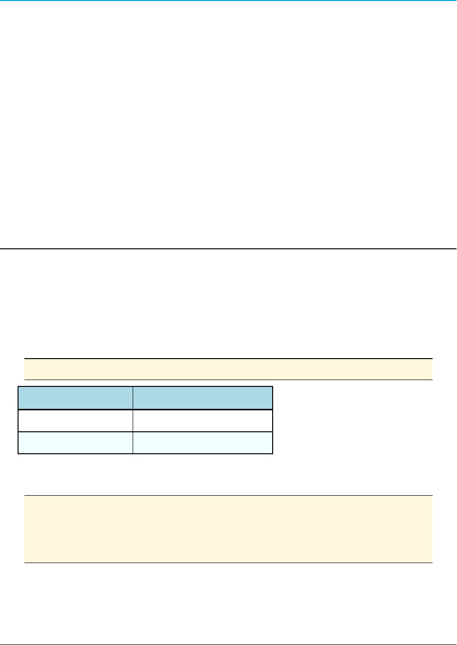
Chapter B: Installation Instructions
The mounting holes on the bottom panel of each WavePoint 10e provide a variety of ways to mount
the WavePoint 10e using either the mounting flanges or the DIN rail bracket provided in the
mounting kit. Mounting kits provide the hardware necessary to attach the flanges or the DIN rail
bracket to the WavePoint 10e, but do NOT contain items such as a the DIN rail or screws to mount
the flanges to an external surface.
Note: Mounting kits must be purchased separately.
FreeWave Part Number Description
POH0031AA DIN Rail Mounting Kit
POH0030AA Wall Mount Bracket Kit (flange)
If mounting outdoors, install the WavePoint 10e in a NEMA-4 rated enclosure. Follow the
installation instructions provided with the NEMA enclosure.
Note: Prior to mounting the WavePoint 10e, write the radio information and the serial
number information on the labels on the back panel. The radio information is helpful
for programming and the Serial Number is required when calling FreeWave
Technical Support for assistance.
LUM0063AARev 05/05/2014 Page 153 of 171
This document is the property of FreeWave Technologies, Inc. and contains proprietary information owned by
FreeWave®. This document cannot be reproduced in whole or in part by any means without written permission from
FreeWave Technologies, Inc.
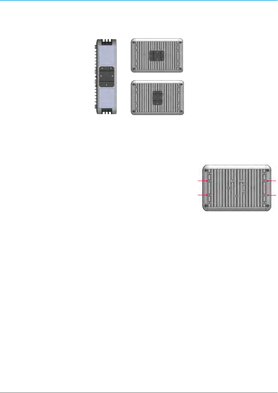
Chapter B: Installation Instructions
Attach the DIN Rail Bracket
1. Determine the orientation that is best for the installation.
2. Using the screws provided, securely attach the bracket to the WavePoint 10e using the
supplied screw holes.
Attach the Mounting Flanges
1. Determine which set of mounting holes on the mounting
flanges is best for the installation.
2. Align the brackets with the screw holes on the bottom panel
of the WavePoint 10e.
3. Securely attach the brackets using the provided screws.
Page 154 of 171 LUM0063AA Rev 05/05/2014
This document is the property of FreeWave Technologies, Inc. and contains proprietary information owned by
FreeWave®. This document cannot be reproduced in whole or in part by any means without written permission from
FreeWave Technologies, Inc.

WavePoint 10e
Appendix C: WavePoint™ Configurations
These are the configurations for the WavePoint 10e.
lWP10e-R100-100-100 on page 155
lWP10e-S100-100-100 on page 155
lWP10e-S200-101-100 on page 155
lWP10e-T100-100-100 on page 156
lWP10e-T200-101-100 on page 156
WP10e-R100-100-100
Model Radio 1 Radio 2 Radio 3 Radio 4 Radio 5 Power Ethernet RS-232 RS-485 USB Enclosure
WP10e-R100-100-100
900MHz
Port 1 -- Y1
Port 2 -- Y2
Not
Installed
Not
Installed
Not
Installed
GPS (option)
Port 1 -- Y4
10.5Vdc-30Vdc
24W
4 2 1 1 Standard
Base
WP10e-S100-100-100
Model Radio 1 Radio 2 Radio 3 Radio 4 Radio 5 Power Ethernet RS-232 RS-485 USB Enclosure
WP10e-S100-100-100 Not
Installed
Not
Installed
2.4GHz
Port 1 -- Y1
Port 2 -- Y2
Port 3 -- Y3
Not
Installed
GPS (option)
Port 1 -- Y4
10.5Vdc-30Vdc
24W
4 2 1 1 Standard
Base
WP10e-S200-101-100
Model Radio 1 Radio 2 Radio 3 Radio 4 Radio 5 Power Ethernet RS-232 RS-485 USB Enclosure
WP10e-S200-101-100 900MHz
Port 1 -- Y3
Not
Installed
2.4GHz
Port 1 -- Y1
Port 2 -- Y2
Not
Installed
GPS (option)
Port 1 -- Y4
10.5Vdc-30Vdc
24W
4 2 1 1 Standard
Base
LUM0063AA Rev 05/05/2014 Page 155 of 171
This document is the property of FreeWave Technologies, Inc. and contains proprietary information owned by FreeWave®. This document cannot be
reproduced in whole or in part by any means without written permission from FreeWave Technologies, Inc.

Appendix C: WavePoint™ Configurations
WP10e-T100-100-100
Model Radio 1 Radio 2 Radio 3 Radio 4 Radio 5 Power Ethernet RS-232 RS-485 USB Enclosure
WP10e-T100-100-100 Not
Installed
Not
Installed
5GHz
Port 1 -- Y1
Port 2 -- Y2
Port 3 -- Y3
Not
Installed
GPS (option)
Port 1 -- Y4
10.5Vdc-30Vdc
24W
4 2 1 1 Standard
Base
WP10e-T200-101-100
Model Radio 1 Radio 2 Radio 3 Radio 4 Radio 5 Power Ethernet RS-232 RS-485 USB Enclosure
WP10e-T200-101-100
900MHz
Port 1 -- Y3
Not
Installed
5GHz
Port 1 -- Y1
Port 2 -- Y2
Not
Installed
GPS (option)
Port 1 -- Y4
10.5Vdc-30Vdc
24W
4 2 1 1 Standard
Base
Page 156 of 171 LUM0063AA Rev 05/05/2014
This document is the property of FreeWave Technologies, Inc. and contains proprietary information owned by FreeWave®. This document cannot be
reproduced in whole or in part by any means without written permission from FreeWave Technologies, Inc.

WavePoint 10e
Appendix D: Bench Test Verification of
WavePoint™ Configuration
Important: For successful replication of this test for a 2.4GHz WavePoint™, the
Required Materials are needed. Where noted, these materials can be ordered from
FreeWave.
Required Materials
Qty Description
1 1 foot RF SMA cable
2 20dB SMA attenuators
2 TNC > SMA couplers (FreeWave Part Number: ECN0313TS)
2
2.4GHz whip stub antennas (FreeWave Part Number: EAN2400SR)
900MHz whip stub antennas (FreeWave Part Number: EAN0900SR)
Note: 5GHz antennas are not available from FreeWave.
RF Cabled Test Procedure
1. Connect a laptop to the WavePoint 10e using an Ethernet cable connected to Ethernet
port 3 or 4.
2. Connect an RF cable between the WavePoint™devices.
3. Use attenuators to establish 40 dB of attenuation.
4. On the laptop, open a web browser.
5. Navigate to the WavePoint 10e default IP address (192.168.1.1).
The WavePoint™ Login window opens.
6. Enter the admin Username and Password.
7. On the Wireless LAN menu, click Radios > Advanced.
The Advanced Radio window opens.
8. In the Radio table, select the radio to change the power settings and right-click.
9. On the right-click menu, select Edit.
The Advanced Radio Configuration dialog box opens.
LUM0063AA Rev 05/05/2014 Page 157 of 171
This document is the property of FreeWave Technologies, Inc. and contains proprietary information owned by
FreeWave®. This document cannot be reproduced in whole or in part by any means without written permission from
FreeWave Technologies, Inc.

Appendix D: Bench Test Verification of WavePoint™ Configuration
10. Click the Mode list box arrow and select ng.
11. Click the Transmit Power list box arrow and select 5.
12. In the Power Constraint text box, enter 5.
13. Click Save to save the changes and close the dialog box.
14. Log out of the WavePoint 10e Configuration window.
15. Repeat Steps 1 to 14 for all WavePoint 10e devices.
16. On the laptop, open either a web browser or a Command prompt.
17. Verify the connection to all WavePoint 10e devices:
lIn the web browser, enter 192.168.1.1 (or the designated WavePoint™IP
address.
lIn the Command prompt, use a Ping command.
Successful connection is verified when the WavePoint™ Login window opens when navigating
from a web browser to a WavePoint 10e IP address or successful ping responses are received.
Open Antenna Test Procedure
1. Connect a laptop to the WavePoint 10e using an Ethernet cable connected to Ethernet
port 3 or 4.
2. Connect the appropriate whip stub antenna to each WavePoint™device.
3. On the Wireless LAN menu, click Radios > Advanced.
The Advanced Radio window opens.
4. In the Radio table, select the radio to change the power settings and right-click.
5. On the right-click menu, select Edit.
The Advanced Radio Configuration dialog box opens.
6. Click the Mode list box arrow and select ng.
7. Click the Transmit Power list box arrow and select 5.
8. In the Power Constraint text box, enter 5.
9. Click Save to save the changes and close the dialog box.
10. Log out of the WavePoint 10e Configuration window.
11. Repeat Steps 1 to 10 for all WavePoint 10e devices.
12. On the laptop, open either a web browser or a Command prompt.
13. Verify the connection to all WavePoint 10e devices:
Page 158 of 171 LUM0063AA Rev 05/05/2014
This document is the property of FreeWave Technologies, Inc. and contains proprietary information owned by
FreeWave®. This document cannot be reproduced in whole or in part by any means without written permission from
FreeWave Technologies, Inc.

WavePoint 10e
lIn the web browser, enter 192.168.1.1 (or the designated WavePoint™IP
address.
lIn the Command prompt, use a Ping command.
Successful connection is verified when the WavePoint™ Login window opens when navigating
from a web browser to a WavePoint 10e IP address or successful ping responses are received.
LUM0063AA Rev 05/05/2014 Page 159 of 171
This document is the property of FreeWave Technologies, Inc. and contains proprietary information owned by
FreeWave®. This document cannot be reproduced in whole or in part by any means without written permission from
FreeWave Technologies, Inc.

Page 160 of 171 LUM0063AA Rev 05/05/2014
This document is the property of FreeWave Technologies, Inc. and contains proprietary information owned by
FreeWave®. This document cannot be reproduced in whole or in part by any means without written permission from
FreeWave Technologies, Inc.

WavePoint 10e
Appendix E: WavePoint 10e Technical
Specifications
Specifications may change at any time without notice. For the most up-to-date specifications
information, see the product's data sheet available at www.freewave.com.
WavePoint™ Technical Specifications
Specification Description
Wireless Interfaces
Network Configurations PTP, PtMP, Fixed Point Mesh, Mobile Mesh
RF Frequency Support
902 to 928 MHz UHF (ITU Region 2)
2.41 to 2.47 GHz (ITU ISM band)
5.15 to 5.825 GHz (U-NII & ISM bands)
800/900 MHz, 1.8/1.9/2.0 GHz
Cellular
RF Modulation Technology
OFDM: BPSK, QPSK, 16-QAM, 64-QAM
With Adaptive Link
Cellular – 3G UMTS/ HSPA
Over the Air Security
WPA, WPA2, WPA-Enterprise,
AES-128, 802.11i
Error Correction FEC, ARQ
SSID Multiple
GPS Yes (optional)
RF Interface 4 TNC, Female
Wired Interfaces
Network Interface
4 10/100 Base-TX (RJ-45) Ethernet
3 LAN Ports, 1 WAN Port
Serial Interface 2 RS-232, DCE, RJ-45
LUM0063AA Rev 05/05/2014 Page 161 of 171
This document is the property of FreeWave Technologies, Inc. and contains proprietary information owned by
FreeWave®. This document cannot be reproduced in whole or in part by any means without written permission from
FreeWave Technologies, Inc.

Appendix E: WavePoint 10e Technical Specifications
WavePoint™ Technical Specifications
Specification Description
1 RS-485, RJ-45
USB Interface Micro USB, Type B for configuration
LAN / WAN
802.3 and 802.3u, IPv4, TCP, UDP, ICMP
DHCP Server and Client, NAT
VLAN Up to 4 VLAN pass-through
LAN Security
RADIUS, X.509 Certificates,
MAC Filtering with ACL
IPsec, AES-128, AES-256, SSH, SSH-2
Management
SNMP v2 and v3, WebGUI, HTTP/HTTPS
RIP v1/v2, STP,* RSTP,* DNS, NAT, NTP
QoS 802.1p/q
Enclosure / Power
Dimensions
241mm x 51mm x 165mm
(9.5" x 2.0" x 6.5")
Weight 1.9kg (4.25lbs.)
Material Aluminum, Powder coated finish
Mounting Options DIN Rail, Brackets
Input Voltage 10 to 30VDC / 802.3at, PoE+ (optional)
Power Consumption 10W to 24W, configuration dependent
Status LEDs Power, GPS, Radio 1 through 4
Environmental / Compliance
Operating Temperature -35°C to +65°C
Humidity 0 to 95% non-condensing
ESD
EN 61000-4-2 with 15kV air and 8kV
contact discharge
Page 162 of 171 LUM0063AA Rev 05/05/2014
This document is the property of FreeWave Technologies, Inc. and contains proprietary information owned by
FreeWave®. This document cannot be reproduced in whole or in part by any means without written permission from
FreeWave Technologies, Inc.
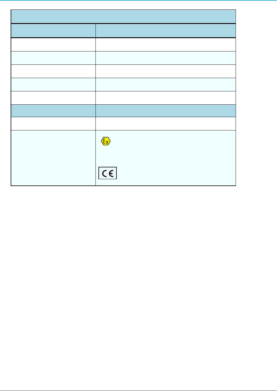
WavePoint 10e
WavePoint™ Technical Specifications
Specification Description
Shock and Vibration ETSI EN 300 019-2-4, 4M3
Transportation ISTA 3A
Compliance RoHS, WEEE, DFS
Wireless Approvals FCC Part 15.247, IC RSS-210
Warranty 1 Year
Product Safety
Standards EN 60079-0:2012 + A11:2013 and EN 60079-15:2010
Labeling Information
II 3 GExnAIICT4Gc
DEMKO 14 ATEX 1306X
LUM0063AA Rev 05/05/2014 Page 163 of 171
This document is the property of FreeWave Technologies, Inc. and contains proprietary information owned by
FreeWave®. This document cannot be reproduced in whole or in part by any means without written permission from
FreeWave Technologies, Inc.

Page 164 of 171 LUM0063AA Rev 05/05/2014
This document is the property of FreeWave Technologies, Inc. and contains proprietary information owned by
FreeWave®. This document cannot be reproduced in whole or in part by any means without written permission from
FreeWave Technologies, Inc.

Glossary
A
AP
Access Point. A device, such as a
wireless router, that allows other wireless
devices to connect to a network or the
Internet. Also referred to as a Gateway if
the device is the point to the wireless
network.
D
DHCP
Dynamic Host Configuration Protocol. A
DHCP server automatically issues IP
addresses within a specified range to
devices on a network. A DHCP client
receives addressing and other
information from the DHCP server.
WavePoint 10e can be set up is a DHCP
server.
F
FQDN
Fully Qualified Domain Name. Also
known as DNS namespace, is a hierarchy
that can logically locate a system based
on its domain identifier.
I
ICMP
Internet Control Message Protocol. Also
known as ICMPv4 and ICMPv6.
Networked devices use this protocol to
send error messages.
ISP
Internet Service Provider.
M
MIMO
Multiple input, multiple output. Use of
multiple transmitters and receiver
antennas to increase data throughput.
MMPE Encryption
Microsoft Point-to-Point Encryption.
N
NTP
Network Time Protocol is a protocol that
works in conjunction with other
synchronization utilities to ensure that all
computers on a given network agree on
the time.
P
PPPoE
Point-to-Point Protocol over Ethernet. A
network configuration used for
establishing a PPP connection using
anEthernet protocol.
PPTP
Point-to-Point Tunneling Protocol. A
networking standard used for connecting
to VPNs. The Point-to-Point Protocol
WavePoint 10e
LUM0063AA Rev 05/05/2014 Page 165 of 171
This document is the property of FreeWave Technologies, Inc. and contains proprietary information owned by
FreeWave®. This document cannot be reproduced in whole or in part by any means without written permission from
FreeWave Technologies, Inc.

(PPP) is wrapped inside the TCP/IP
protocol, allowing for a secure
connection.
PVID
Port VLAN ID.
R
Rogue AP
Any access point that is installed in a
network that is not authorized for
operation within that network.
RSTP
Rapid Spanning Tree Protocol.
S
STP
Spanning Tree Protocol. A link
management protocol for access control
bridges. STP provides path redundancy
while preventing bridge loops created by
multiple active paths between points.
T
TCP/IP
Transmission Control Protocol/Internet
Protocol. A protocol for communication
between computers. Used as a standard
for transmitting data over networks and as
the basis for standard Internet protocols.
W
WPA
Wi-Fi Protected Access. An
authentication protocol used to protect
wireless networks from unauthorized
access.
Page 166 of 171 LUM0063AA Rev 05/05/2014
This document is the property of FreeWave Technologies, Inc. and contains proprietary information owned by
FreeWave®. This document cannot be reproduced in whole or in part by any means without written permission from
FreeWave Technologies, Inc.
Glossary

Index
A
accessories 20
antennas, FCC certified 23
authentication certificates
about 139
self certificates 141
trusted 139
B
binding IP addresses 54
C
certificates, authentication
about 139
self certificates 140-141
trusted 139
configuration pages, overview 34
configurations
identifying 21
current settings, backing up 131
D
date and time
NTP server setup 143
setting 143
troubleshooting 149
device mode 47
DHCP server, enabling 39
F
factory default settings 123, 133, 151
firmware
upgrading 130
I
IC notifications 3
installation 153
Internet connections
DHCP 44
PPPoE 45
static IP 43
troubleshooting 147
introduction 17
K
key features 18
L
LAN
IPv4 setup
IP address 38
subnet mask 38
WavePoint 10e
LUM0063AA Rev 05/05/2014 Page 167 of 171
This document is the property of FreeWave Technologies, Inc. and contains proprietary information owned by
FreeWave®. This document cannot be reproduced in whole or in part by any means without written permission from
FreeWave Technologies, Inc.

legal notifications
IC 3
load balancing, WAN 51
logging in 32
login policies 125
logs
emailing 136
external servers, sending to 138
overview 134
packet traffic 135
SysLog Server, sending to 138
system events 134
M
MAC address filtering 91
management
features 18
model numbers
identifying 21
N
network deployments 31
network services
features 18
P
Point-to-Multipoint example configuration 80
power
connecting 30
protocol bindings, setting 52
R
radios
advanced settings 85
rebooting 133
requirements 19
RIPv1 and RIPv2 57
routing
RIP 57
static routes 55
Routing Information Protocol 57
routing mode 47
S
schedules, wireless networks 97
security
features 19
settings
backing up current settings 131
factory defaults 151
restoring from file 132
software
upgrading 130
static routes 55
Page 168 of 171 LUM0063AA Rev 05/05/2014
This document is the property of FreeWave Technologies, Inc. and contains proprietary information owned by
FreeWave®. This document cannot be reproduced in whole or in part by any means without written permission from
FreeWave Technologies, Inc.
Index

T
template files, creating 131
time and date
NTP server setup 143
setting 143
troubleshooting
date and time 149
Internet connection 147
U
user groups
deleting 128
policies 128
browser 126
IP 127
login 125
users
adding 129
deleting 130
editing 129
V
VLANs
associating port traffic 62
enabling 59
mapping to LAN subnets 60
VPN tunnels
configuring 109
W
WAN setup
DHCP 44
failover 50
load balancing 51
MTU size 49
multiple WANs 42, 50-51
physical settings 49
port binding 52
port speed 49
port traffic 52
PPPoE 45
PPTP 46
responding to Ping 49
static 43
warranty 2
web pages, overview 34
wireless networks
availability 97
configuring 82
modes 18
Point-to-Multipoint example con-
figurations 80
schedules 97
WavePoint 10e
LUM0063AA Rev 05/05/2014 Page 169 of 171
This document is the property of FreeWave Technologies, Inc. and contains proprietary information owned by
FreeWave®. This document cannot be reproduced in whole or in part by any means without written permission from
FreeWave Technologies, Inc.

security
authorized access list 91
EAP authentication 95
MAC address restrictions 92
RADIUS servers 95
rogue access point detection 94
virtual APs 89
Page 170 of 171 LUM0063AA Rev 05/05/2014
This document is the property of FreeWave Technologies, Inc. and contains proprietary information owned by
FreeWave®. This document cannot be reproduced in whole or in part by any means without written permission from
FreeWave Technologies, Inc.
Index

Page 171 of 171 LUM0063AA Rev 05/05/2014
This document is the property of FreeWave Technologies, Inc. and contains proprietary information owned by
FreeWave®. This document cannot be reproduced in whole or in part by any means without written permission from
FreeWave Technologies, Inc.