FreeWave Technologies PMT0101AA Z9-C, Z9-T User Manual My
FreeWave Technologies Inc. Z9-C, Z9-T My
UserManual.wiki
>
FreeWave Technologies
>
PMT0101AA User Manual
>
user manual
Contents
1.
user manual
2.
User Manual
3.
Manual
user manual
Navigation menu
Upload a User Manual
Namespaces
Wiki Guide
HTML
PDF
Info
Views
User Manual
Discussion / Help
Navigation
![PrefacePage 8 of 27 LUM0075AA Rev Feb-2016This document is the property of FreeWave Technologies, Inc. and contains proprietary information owned byFreeWave®. This document cannot be reproduced in whole or in part by any means without written permission fromFreeWave Technologies, Inc.Printing this DocumentThis document is set to print double-sided with a front cover and a back cover. Viewing thisdocument online with a PDF viewer, may show pages intentionally left blank to accommodate thedouble-sided printing.Document StylesThis document uses these styles:lFreeWave applications appear as: FreeWave.lParameter setting text appears as: [Page=radioSettings]lFile names appear as: configuration.cfg.lFile paths appear as: C:\Program Files (x86)\FreeWave Technologies.lUser-entered text appears as: xxxxxxxxx.l3rd-party names appear as: Notepad®.Caution: Indicates a situation that MAY cause damage to personnel, the radio, data, ornetwork.Example: Provides example information of the related text.FreeWave Recommends: Identifies FreeWave recommendation information.Important!: Provides crucial information relevant to the text or procedure.Note: Emphasis of specific information relevant to the text or procedure.Provides time saving or informative suggestions about using the product.Warning!Indicates a situation that WILL cause damage to personnel, the radio, data, ornetwork.Documentation FeedbackSend comments or questions about this document's content to techpubs@freewave.com. In theemail, include the title of the document or the document's part number and revision letter (found inthe footer).](https://usermanual.wiki/FreeWave-Technologies/PMT0101AA.user-manual/User-Guide-2926770-Page-8.png)
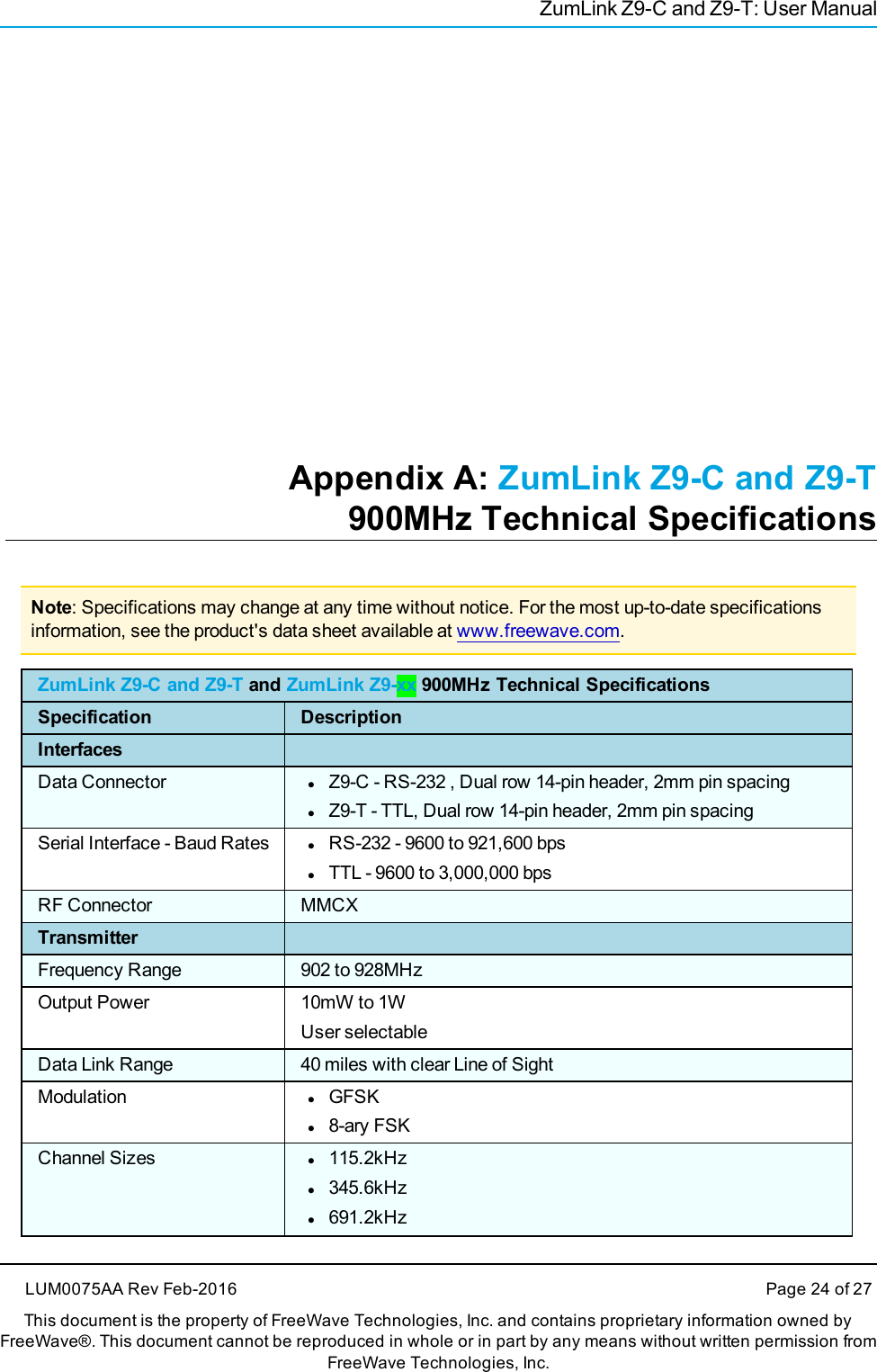
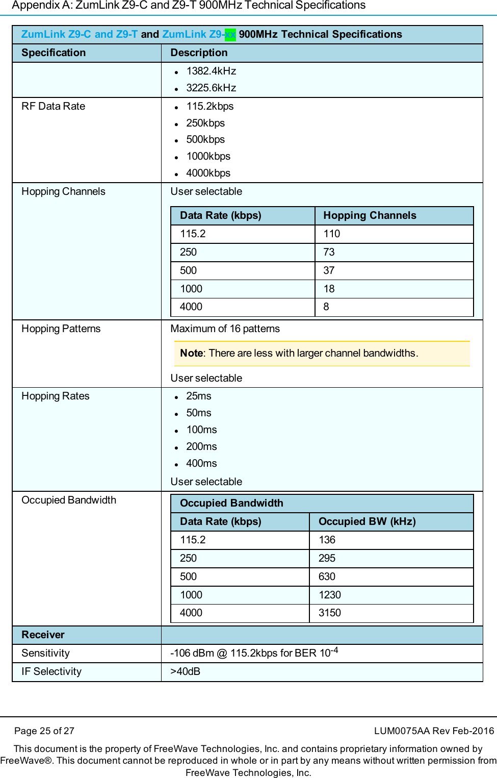
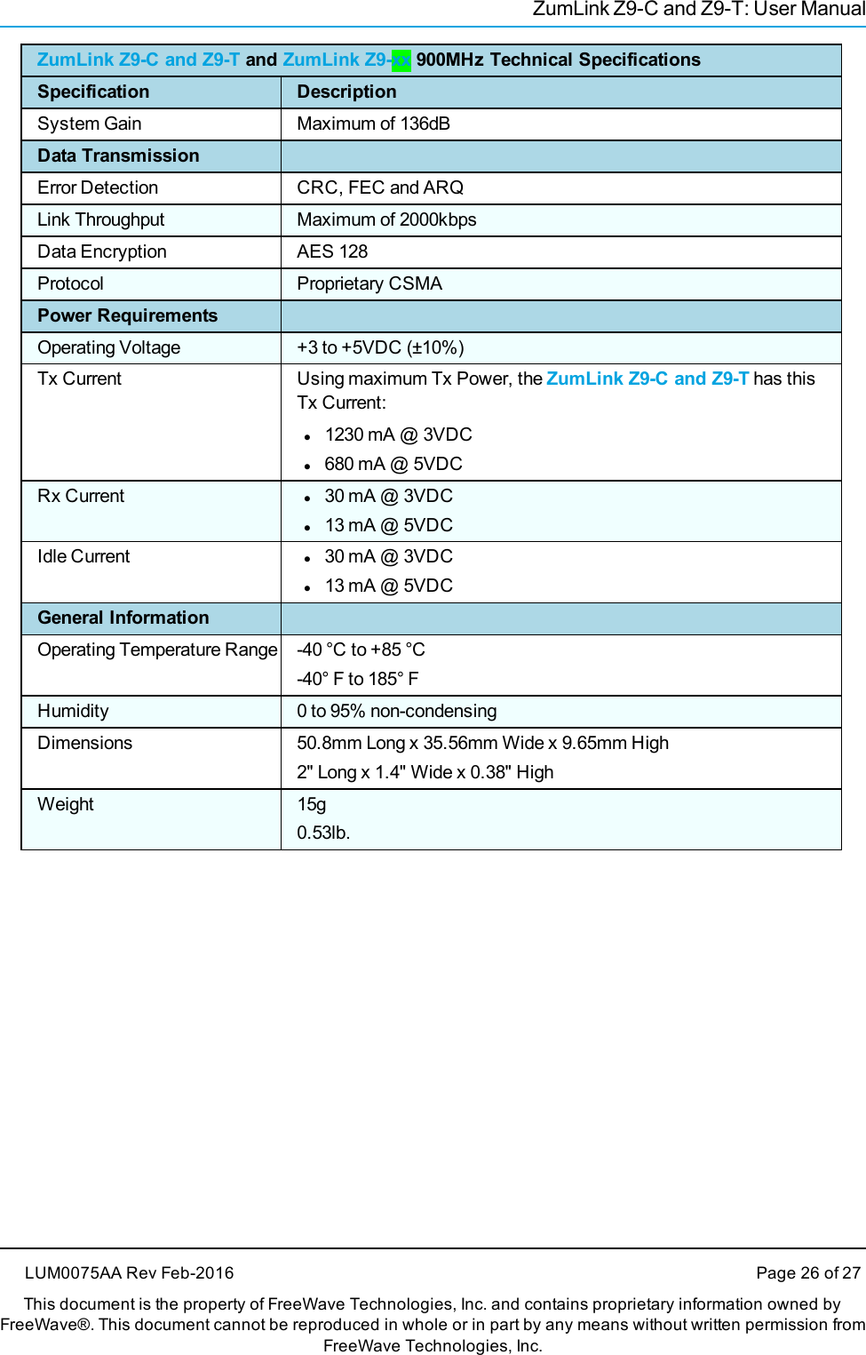
![4. ZumLink Z9-C and Z9-T Settings and DescriptionsThese are the Page Settings for the ZumLink Z9-C and Z9-T:lsystemInfo (on page 18)lradioSettings (on page 19)lconfig (on page 23)systemInfoSystem Info - ZumLink Z9-C and Z9-TZumLink Z9-PE Settings and DescriptionsPage CLI Command Description[Page=systemInfo] systemInfo.deviceId= This is the Modbus ID selected for the device.lThis number is used to identify the ZumLink Z9-C and Z9-T forpolling.lThis number MUST be unique to all devices in the ZumLinknetwork.lThe valid entry range is 1 to 255.Note: The default value is 1.[Page=systemInfo] systemInfo.deviceName= This is a site name only for the user's reference.LUM0075AA Rev Feb-2016 Page 18 of 27This document is the property of FreeWave Technologies, Inc. and contains proprietary information owned by FreeWave®. This document cannot bereproduced in whole or in part by any means without written permission from FreeWave Technologies, Inc.](https://usermanual.wiki/FreeWave-Technologies/PMT0101AA.user-manual/User-Guide-2926770-Page-18.png)
![4. ZumLink Z9-C and Z9-T Settings and DescriptionsPage 19 of 27 LUM0075AA Rev Feb-2016This document is the property of FreeWave Technologies, Inc. and contains proprietary information owned by FreeWave®. This document cannot bereproduced in whole or in part by any means without written permission from FreeWave Technologies, Inc.System Info - ZumLink Z9-C and Z9-TZumLink Z9-PE Settings and DescriptionsPage CLI Command DescriptionFreeWave Recommends: Use a name relevant to the site’slocation (e.g., Site 5).[Page=systemInfo] systemInfo.deviceFirmwareVersion= This setting identifies the ZumLink firmware version.[Page=systemInfo] systemInfo.macAddress= This setting designates the MAC Address of the ZumLink.radioSettingsradioSettings - ZumLink Settings and DescriptionsPage CLI Command Description[Page=radioSettings] radioSettings.txPower= 900MHzlThis setting defines the transmit power.lA higher power can be used to increase link margin.lUse lower a transmit power to reduce interference when multiple radiolinks are in close proximity.lEnter 0 (zero) to 30Note: The default value is 5.[Page=radioSettings] radioSettings.rfDataRate= Note: This is a ZumLink Golden Setting.This setting defines the RF link data rate speed in bits per second.A higher data rate provides more throughput at the expense of link distanceor fade margin.Important!: Both the Gateway and Endpoint radios MUST use thesame value for this setting.The options are:](https://usermanual.wiki/FreeWave-Technologies/PMT0101AA.user-manual/User-Guide-2926770-Page-19.png)
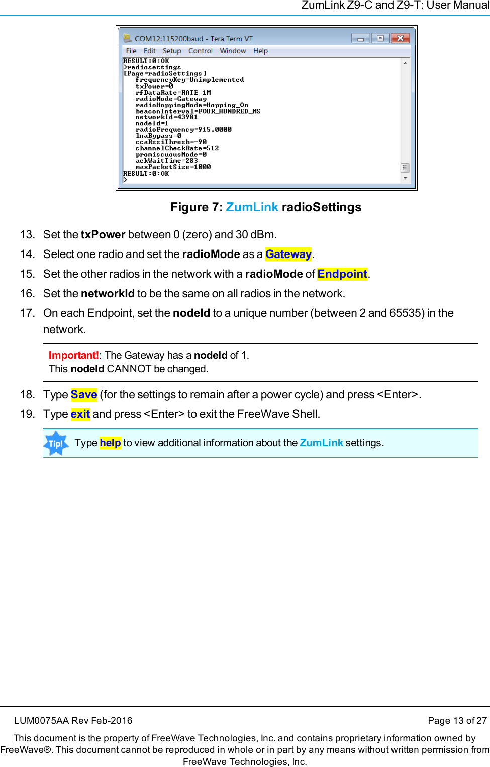
![ZumLink Z9-C and Z9-TradioSettings - ZumLink Settings and DescriptionsPage CLI Command DescriptionlRATE_1MlRATE_500KlRATE_250KlRATE_115.2KNote: The default value is RATE_1M.[Page=radioSettings] radioSettings.mode= This setting designates the device as a Gateway or Endpoint unit.lEach network should have only ONE Gateway unit.lThe remaining units should be configured as Endpoints.Note: The Gateway device will always have a nodeId of value 1.FreeWave Recommends: Use the default settings for normaloperation.The options are:lEndpointlGatewayNote: The default value is Endpoint.[Page=radioSettings] radioSettings.networkId= This is the Network Identifier.lThis setting can be used to subdivide traffic on radio units.lRadio units can only communicate with other units that have the samenetworkId setting.Note: If radios are on the same frequency they will still receive datafrom radios of a different networkId, but the data is dropped.Enter any number between 1 and 65533.LUM0075AA Rev Feb-2016 Page 20 of 27This document is the property of FreeWave Technologies, Inc. and contains proprietary information owned by FreeWave®. This document cannot bereproduced in whole or in part by any means without written permission from FreeWave Technologies, Inc.](https://usermanual.wiki/FreeWave-Technologies/PMT0101AA.user-manual/User-Guide-2926770-Page-20.png)
![4. ZumLink Z9-C and Z9-T Settings and DescriptionsPage 21 of 27 LUM0075AA Rev Feb-2016This document is the property of FreeWave Technologies, Inc. and contains proprietary information owned by FreeWave®. This document cannot bereproduced in whole or in part by any means without written permission from FreeWave Technologies, Inc.radioSettings - ZumLink Settings and DescriptionsPage CLI Command DescriptionNote: The default value is 51966.[Page=radioSettings] radioSettings.nodeId= This setting defines the Node ID.lEach radio with the same networkId must have a unique nodeId.lEnter any number between 1 and 65533.Note: The default value is 64206.The Gateway device will always have a nodeId of value 1.[Page=radioSettings] radioSettings.radioFrequency= This setting designates the Operating Center Frequency in MHz.lThis parameter ONLY takes effect whenradioHoppingMode=Hopping_Off.lAll radios in a network must have the same frequency.lEnter a frequency between 903.25 and 926.75.Note: The default value is 915.000.[Page=radioSettings] radioSettings.radioHoppingMode= This parameter is used to enable or disable frequency hopping.lFor rfDataRate values less then 500kbs, the radioHoppingMode isforced On.lFor all other rates, the radioHoppingMode is optional.lFor rfDataRate values greater than 500kbs, the choice of hopping modeshould be selected based on network frequency planning and channelconditions.Important!: Both the Gateway and Endpoint radios MUST use thesame value for this setting.The format of the option is:lHopping_Off](https://usermanual.wiki/FreeWave-Technologies/PMT0101AA.user-manual/User-Guide-2926770-Page-21.png)
![ZumLink Z9-C and Z9-TradioSettings - ZumLink Settings and DescriptionsPage CLI Command DescriptionlHopping_OnExample:radioSettings.radioHoppingMode=Hopping_On.Note: The default value is Hopping_Off.[Page=radioSettings] radioSettings.beaconInterval= The beaconInterval controls how often a Gateway radio sends out a beaconpacket and changes to the next radio frequency in the hopping pattern.lA longer beaconInterval will give the system better throughput inchannel environments where interference is minimal.lThroughput can be improved in some situations with shorter beaconintervals.Important!: Both the Gateway and Endpoint radios MUST use thesame value for this setting.The options are:lONE_SEClFIVE_SECSlTEN_SECSlONE_HUNDRED_MSlTWO_HUNDRED_MSlFOUR_HUNDRED_MSExample:radioSettings.beaconInterval=TEN_SECS.Note: The default value is ONE_HUNDRED_MS.[Page=radioSettings] lnaBypass= LNA BypasslThe options are 0 (zero) and 1.LUM0075AA Rev Feb-2016 Page 22 of 27This document is the property of FreeWave Technologies, Inc. and contains proprietary information owned by FreeWave®. This document cannot bereproduced in whole or in part by any means without written permission from FreeWave Technologies, Inc.](https://usermanual.wiki/FreeWave-Technologies/PMT0101AA.user-manual/User-Guide-2926770-Page-22.png)
![4. ZumLink Z9-C and Z9-T Settings and DescriptionsPage 23 of 27 LUM0075AA Rev Feb-2016This document is the property of FreeWave Technologies, Inc. and contains proprietary information owned by FreeWave®. This document cannot bereproduced in whole or in part by any means without written permission from FreeWave Technologies, Inc.radioSettings - ZumLink Settings and DescriptionsPage CLI Command DescriptionlWhen set to a value of 1, the LNA of the radio module is bypassed.lIt can be useful to bypass the LNA if there is a presence of strong signalsin band and packet reception is not good.Note: The default value is 0 (zero).configconfig - ZumLink Settings and DescriptionsPage CLI Command Description[Page=config] config.factoryDefaults= This setting identifies the ZumLink factory defaults.[Page=config] config.save= This setting saves changes made to the ZumLink configuration.](https://usermanual.wiki/FreeWave-Technologies/PMT0101AA.user-manual/User-Guide-2926770-Page-23.png)