FreeWave Technologies PRW1001ER mini-PCI radio Module User Manual Users manual
FreeWave Technologies Inc. mini-PCI radio Module Users manual
Contents
- 1. User manual
- 2. Users manual
- 3. User Manual
Users manual
WavePoint 10e
Software 1
.
0
.
38
User Ma
nu
a
l
Part Number: LUM0063AA
Revision: A
Last Updated: 03/21/2014

Page 2 of 165 LUM0063AA Rev A
This document is the property of FreeWave Technologies, Inc. and contains proprietary information owned by
FreeWave®. This document cannot be reproduced in whole or in part by any means without written permission
f
rom
FreeWave Technologies,
I
n
c.
Warranty
FreeWave Technologies, Inc. warrants your FreeWave® Wireless Data Transceiver against defects in materials and
manufacturing for a period of one year from the date of shipment, depending on model number. In the event of a
Product failure due to materials or workmanship, FreeWave will, at its discretion, repair or replace the Product. For
evaluation of Warranty coverage, return the Product to FreeWave upon receiving a Return Material Authorization
(RMA).
FreeWave’s policy for handling WavePoint products returned due to a fault, after complaint is validated by
FreeWave’s Customer Support, is to replace the product with a new or refurbished unit upon receipt of reported
faulty product. This means failure analysis on said product will not be performed and reported to customers. All
failed units will be bagged and tagged so they can be revisited in the event that FreeWave experiences a high
degree of failures or a trend. At which time, FreeWave will perform a root-cause analysis and take the appropriate
corrective actions. Any visual or external damage noted on returned units will be communicated back to customers
and may void the warranty, at which time, a Purchase Order (PO) will be requested from the customer for product
replacement
In no event will FreeWave Technologies, Inc., its suppliers, or its licensors be liable for any damages arising from
the use of or inability to use this Product. This includes business interruption, loss of business information, or other
loss which may arise from the use of this Product. OEM customer’s warranty periods can vary.
Warranty Policy will not apply in the following circumstances:
1. If Product repair, adjustments, or parts replacements are required due to accident, neglect, or undue
physical, electrical, or electromagnetic stress.
2. If Product is used outside of FreeWave specifications as stated in the Product's data sheet.
3. If Product has been modified, repaired, or altered by Customer unless FreeWave specifically authorized
such alterations in each instance in writing. This includes the addition of conformal coating.
Special Rate Replacement Option
A special rate replacement option is offered to non-warranty returns or upgrades. The option to purchase the
replacement unit at this special rate is only valid for that RMA. The special replacement rate option expires if not
exercised within 30 days of final disposition of RMA.
RestrictedRights
Any product names mentioned in this manual may be trademarks or registered trademarks of their respective
companies and are hereby acknowledged.
This manual is for use by purchasers and other authorized users of FreeWave products.
No part of this manual may be reproduced or transmitted in any form or by any means, electronic or mechanical, or
for any purpose without the express written permission of FreeWave Technologies, Inc. FreeWave reserves the
right to make changes to this manual without notice. FreeWave assumes no responsibility or liability for the use of
this manual or the infringement of any copyright or other proprietary right.
FreeWave Technologies,
In
c
.
Boulder, C
O
303
.
381
.
9200
Toll Free: 1
.
866
.
923
.
6168
Printed in the United States of America. Fax: 303.786.9948
Copyright © 2014 by FreeWave Technologies, Inc. All rights reserved. www.freewave.com

Wa
v
ePoint 10e
LUM0063AA Rev A Page 3 of 165
This document is the property of FreeWave Technologies, Inc. and contains proprietary information owned by
FreeWave®. This document cannot be reproduced in whole or in part by any means without written permission
f
rom
FreeWave Technologies,
I
n
c.
FreeWave Technologies, Inc. products may be subject to control by the Export Administration Regulations
(EAR) and/or the International Traffic in Arms Regulations (ITAR). Export, re-export, or transfer of these
products without required authorization from the U.S. Department of Commerce, Bureau of Industry and
Security, or the U.S. Department of State, Directorate of Defense Trade Controls, as applicable, is prohibited.
Any party exporting, re-exporting, or transferring FreeWave products is responsible for obtaining all
necessary U.S. government authorizations required to ensure compliance with these and other applicable
U.S. laws. Consult with your legal counsel for further guidance.
FCCNotifications
This device complies with part 15 of the FCC rules. Operation is subject to the following two conditions: 1) This
device may not cause harmful interference and 2) this device must accept any interference received, including
interference that may cause undesired operation.
The content of this guide covers FreeWave Technologies, Inc. models sold under FCC ID: KNYPRW1001ER,
KNYASM1101CR, KNYASM1101CR, KNYASM1101CR, KNYPRW1001EC, KNYPRW1001EC.
All models sold under the FCC ID(s) listed above must be installed professionally and are only approved for use
when installed in devices produced by FreeWave Technologies or third party OEMs with the express written
approval of FreeWave Technologies, Inc. Changes or modifications should not be made to the device.
ICNotifications
This device complies with Industry Canada license-exempt RSS standard(s). Operation is subject to the following
two conditions: (1) this device may not cause interference, and (2) this device must accept any interference,
including interference that may cause undesired operation of the device.
Ce dispositif est conforme aux normes permis-exemptes du Canada RSS d'industrie. L'opération est sujette aux
deux conditions suivantes : (1) ce dispositif peut ne pas causer l'interférence, et (2) ce dispositif doit accepter
n'importe quelle interférence, y compris l'interférence qui peut causer le fonctionnement peu désiré du dispositif.

Page 4 of 165 LUM0063AA Rev A
This document is the property of FreeWave Technologies, Inc. and contains proprietary information owned by
FreeWave®. This document cannot be reproduced in whole or in part by any means without written permission
f
rom
FreeWave Technologies,
I
n
c.

LUM0063AA Rev A Page 5 of 165
This document is the property of FreeWave Technologies, Inc. and contains proprietary information owned by
FreeWave®. This document cannot be reproduced in whole or in part by any means without written permission
f
rom
FreeWave Technologies,
I
n
c.
Wa
v
ePoint 10e
TableofC
ont
e
nts
Preface 17
Chapter 1: Introduction 19
Key Features and Supported Protocols 20
Wireless Operating Modes 20
Available Network Services 20
Device Management 20
Network Security 21
Requirements 21
Installation Settings 21
Equipment and Configuration 22
Accessories 22
Product Variations 23
WavePoint 10e Labels 23
Sample: Configuration Label 23
Sample: Port Assignment Label 23
WavePoint™ Components 24
Data Connectors 24
RF Connectors 24
Certified Antennas 25
Antenna Installation Warning 25
900MHz Antennas 25
2.4GHz Antennas 26
5GHz Antennas 26
Antenna Installation 27

Page 6 of 165 LUM0063AA Rev A
This document is the property of FreeWave Technologies, Inc. and contains proprietary information owned by
FreeWave®. This document cannot be reproduced in whole or in part by any means without written permission
f
rom
FreeWave Technologies,
I
n
c.
Placement Considerations 27
Transmit Power Settings 28
RF Loss 28
WavePoint™ EIRP Limits 29
RF Considerations for 2.4 GHz ISM Band 29
Peak Power Output 29
Point-to-Point Link 30
Guidelines 30
Point-to-Multi-Point Link 31
RF Considerations for 900MHz ISM Band 31
WavePoint™ GUI to Actual RF Power 31
Connect Power 32
Network Deployment Scenarios 32
Wired Access 33
Wireless Access 33
Multiple Repeaters 33
Connecting and Logging In 33
Configuration Pages 35
Searching for Menus 36
Chapter 2: Configuring Basic WavePoint™ Network Features 37
Setting the Device IP Address and Subnet 38
IPv4 Networks - Set the IP Address and Subnet 38
Reserved Subnets 38
Procedure 38
Enabling and Configuring DHCP 39

LUM0063AA Rev A Page 7 of 165
This document is the property of FreeWave Technologies, Inc. and contains proprietary information owned by
FreeWave®. This document cannot be reproduced in whole or in part by any means without written permission
f
rom
FreeWave Technologies,
I
n
c.
Wa
v
ePoint 10e
IPv4 Addressing - Enable and Configure DHCP 39
Reserving IP Addresses 41
Reserve IP Addresses in an IPv4 Network 41
Delete a Specific LAN Reserved IP Address 41
Delete all Reserved IP Addresses 42
Using Multiple
WANs
or a Single WAN 42
Indicate the Number of
WANs
in Use 42
Configuring the WAN in an IPv4 Network 43
Defining WAN Connections Using Static IP Addresses 43
Procedure 43
Defining WAN Connections Using DHCP 44
Procedure 44
Defining WAN Connections Using PPPoE 45
Procedure 45
Defining WAN Connections Using PPTP 46
Procedure 46
Setting the Device Mode 47
Procedure 47
Chapter 3: Additional Data Networking Features 49
Defining Physical WAN Port Settings 49
Procedure 49
Setting Up Auto Fail-Over in Multi-WAN Environments 50
Procedure 50
Balancing Data Flow in Multi-WAN Environments 51
Procedure 51

Page 8 of 165 LUM0063AA Rev A
This document is the property of FreeWave Technologies, Inc. and contains proprietary information owned by
FreeWave®. This document cannot be reproduced in whole or in part by any means without written permission
f
rom
FreeWave Technologies,
I
n
c.
Restricting the Traffic Type for Each WAN Port 52
Configure a Traffic Restriction (Protocol Binding) for a WAN Port 53
Enable or Disable a Protocol Binding Configuration 54
Delete a Protocol Binding Configuration 54
Binding an IP Address to a MAC Address 54
Procedure 54
Data Routing 55
Defining Static Routing Rules 55
Define a Static IPv4 Route 56
Delete an Existing Static Route 57
Defining Routing Internet Protocol Rules 57
Define RIP in IPv4 Networks 58
Virtual Local Area Networks (VLANs) 58
Enabling VLANs 59
Procedure 59
Defining VLANs in the Network 59
Procedure 59
Delete an Available VLAN 60
Mapping VLANs to LAN Subnets 60
Procedure 61
Associating Port Traffic to a VLAN 62
Procedure 62
WaveMesh 64
WaveMesh Methods 64
Example: WaveMesh Routing Diagram 65

LUM0063AA Rev A Page 9 of 165
This document is the property of FreeWave Technologies, Inc. and contains proprietary information owned by
FreeWave®. This document cannot be reproduced in whole or in part by any means without written permission
f
rom
FreeWave Technologies,
I
n
c.
Wa
v
ePoint 10e
WaveMesh using Auto Selection Method 66
WaveMesh using Branch Selection Method 69
WaveMesh using a List Selection Method 72
Chapter 4: Configuring Wireless Access 79
Example: Point-to-Point Configuration 79
Configuring a Point-to-Point Network 80
Point-to-Multipoint Configuration Examples 80
Example 1: Point-to-Multipoint 80
Setup Procedure 80
Example 2: Point-to-Multipoint 81
Procedure 81
Configuring Wireless Communication 82
Procedure 83
Bench Test Verification of WavePoint™ Configuration 85
Required Materials 85
RF Cabled Test Procedure 86
Open Antenna Test Procedure 86
Defining Advanced Radio Settings 87
Procedure 88
Verify the Wireless Connection 91
Enabling Virtual Access Points 91
Procedure 92
Change a Virtual Access Point's Settings 92
Wireless Security 93
Authorizing Wireless Access 93

Page 10 of 165 LUM0063AA Rev A
This document is the property of FreeWave Technologies, Inc. and contains proprietary information owned by
FreeWave®. This document cannot be reproduced in whole or in part by any means without written permission
f
rom
FreeWave Technologies,
I
n
c.
Procedure 93
Restricting Access by MAC Address 95
Set the ACL Policy Type 95
Add or Edit MAC Addresses in the ACL List 96
Delete a Device from the List 96
Enabling Rogue Access Point Detection 96
Procedure 96
Review Devices that Attempted to Access the Network 97
Defining EAP Authentication and External RADIUS Servers 97
Configure the EAP Authentication 97
Define an External RADIUS Server 98
Scheduling When Wireless Connections are Available 99
Define and Enable a Schedule for a Wireless Connection 99
Disable a Schedule 100
Chapter 5: Security 101
Firewall Overview 101
Firewall Basic Policies 101
Default Outbound Policy 101
Set the Outbound Traffic Policy 102
Firewall Rules 102
Creating Firewall Rules for IPv4 102
Delete an IPv4 Firewall Rule 105
Disable an IPv4 Firewall Rule 105
Custom Services 105
Configure Custom Service Settings 106

LUM0063AA Rev A Page 11 of 165
This document is the property of FreeWave Technologies, Inc. and contains proprietary information owned by
FreeWave®. This document cannot be reproduced in whole or in part by any means without written permission
f
rom
FreeWave Technologies,
I
n
c.
Wa
v
ePoint 10e
Delete an Existing Custom Service 107
VPN Passthrough 107
Procedure 107
Firewall Schedules 107
Configuring Firewall Schedules 108
Delete a Firewall Schedule 108
Application Rules 109
Configuring Application Rules 109
Delete an Application Rule 110
Application Rules Status 111
VPN Tunnels and IPsec 111
Configuring a VPN Tunnel with IPsec 111
Configuring a Basic VPN Tunnel 111
IPsec Policies 112
Configuring an IPsec VPN Policy 113
Configuring an Auto Policy that uses IKE to Perform Negotiations between Two VPN
Clients 116
Configure Phase 2 Auto Policy Parameters 119
Configure Phase 2 Manual Policy Parameters 120
Delete an
IPSec
VPN Policy 121
Edit the Default DHCP Range 121
Chapter 6: Management and Administration 123
Set Up Remote Access to the WAN Port 124
Procedure 124
User Access Management 124

Page 12 of 165 LUM0063AA Rev A
This document is the property of FreeWave Technologies, Inc. and contains proprietary information owned by
FreeWave®. This document cannot be reproduced in whole or in part by any means without written permission
f
rom
FreeWave Technologies,
I
n
c.
Users and Groups 125
Users 125
Groups 125
Factory Defined Users 125
admin 125
guest 126
Adding and Editing User Groups 126
Default User Groups 126
Procedure 126
Define and Assign User Group Login Policies 127
Procedure 128
Define User Group Browser Policies 128
Procedure 128
Define User Group IP Policies 129
Procedure 129
Deleting User Groups Policies 130
Delete a Single User Group Policy 130
Delete all User Policies in a List 130
Deleting User Groups 130
Delete a User Group 130
Delete all User Groups 131
Adding and Editing Users 131
Procedure 131
Deleting Users 132
Procedure 132

LUM0063AA Rev A Page 13 of 165
This document is the property of FreeWave Technologies, Inc. and contains proprietary information owned by
FreeWave®. This document cannot be reproduced in whole or in part by any means without written permission
f
rom
FreeWave Technologies,
I
n
c.
Wa
v
ePoint 10e
Software Maintenance 132
Upgrade the WavePoint 10e Software 132
Procedure 133
Back Up Configuration Settings 133
Procedure 134
Restore Configuration Settings 134
Procedure 134
Restoring Factory Default Settings 135
Procedure 135
Rebooting 135
Procedure 135
System Logging 136
Set Up System Event Logging 136
Procedure 137
Logging Packet Traffic 137
Log Packet Traffic in an IPv4 Network 137
Sending Log Messages to Email Addresses 138
Procedure 139
Sending Logs to Syslog Servers 140
Procedure 140
Simple Network Management Protocol (SNMP) 140
Authentication Certificates 141
Adding Trusted Certificates (CA Certificates) 141
Procedure 141
Generating Self Certificate Requests 142

Page 14 of 165 LUM0063AA Rev A
This document is the property of FreeWave Technologies, Inc. and contains proprietary information owned by
FreeWave®. This document cannot be reproduced in whole or in part by any means without written permission
f
rom
FreeWave Technologies,
I
n
c.
Procedure 142
Adding Active Self Certificates 143
Procedure 144
Deleting Certificates 144
Delete a Single Certificate 144
Delete all Certificates 144
Setting the Date and Time 145
Use an NTP Server to Set the Date and Time 145
Manually Set the Date and Time 146
System Statistics 146
Procedure 147
Chapter 7: Diagnostics and Troubleshooting 149
General Troubleshooting 149
Internet Connection and Browser Display 149
Cannot Access the Configuration Pages from a Computer on the LAN 149
Configuration Changes are not Saving 150
WavePoint 10e cannot Obtain an IP address from the ISP 150
WavePoint 10e can Obtain an IP address but the PC is Unable to Load Internet Pages 150
Date and Time 151
The Date Shown in the Log Files is January 1, 1970 151
The Time is off by One Hour 151
Chapter 8: Installation Instructions 153
Attach the DIN Rail Bracket 154
Attach the Mounting Flanges 154
Appendix A: Factory Default Settings 155

LUM0063AA Rev A Page 15 of 165
This document is the property of FreeWave Technologies, Inc. and contains proprietary information owned by
FreeWave®. This document cannot be reproduced in whole or in part by any means without written permission
f
rom
FreeWave Technologies,
I
n
c.
Wa
v
ePoint 10e
Appendix B: WavePoint™ Configurations 157
WP10e-R100-100-100 157
WP10e-S100-100-100 157
WP10e-S200-101-100 157
WP10e-T100-100-100 158
WP10e-T200-101-100 158
Glossary 159
Index 161

Page 16 of 165 LUM0063AA Rev A
This document is the property of FreeWave Technologies, Inc. and contains proprietary information owned by
FreeWave®. This document cannot be reproduced in whole or in part by any means without written permission
f
rom
FreeWave Technologies,
I
n
c.

LUM0063AA Rev A Page 17 of 165
This document is the property of FreeWave Technologies, Inc. and contains proprietary information owned by
FreeWave®. This document cannot be reproduced in whole or in part by any means without written permission
f
rom
FreeWave Technologies,
I
n
c.
P
reface
This document provides information to configure and setup the WavePoint 10e device and
includes:
l
An introduction to the WavePoint 10e device and its key features.
l
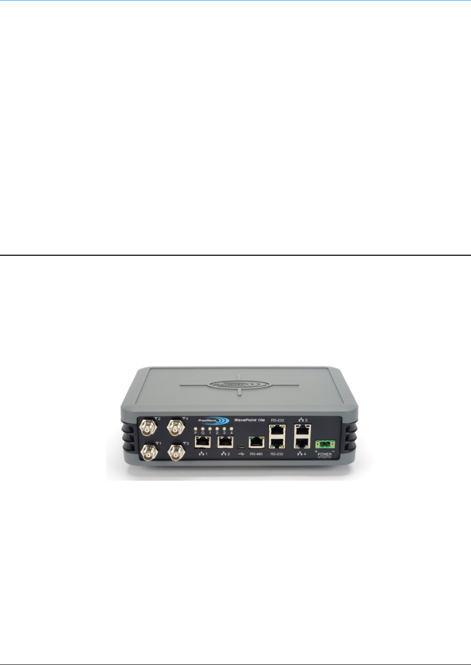
Physical components of the device including its ports and LEDs.
l
Configuring a basic WavePoint 10e network.
l
Setting up wireless access.
l
Using a WavePoint 10e for local communication or as a Wi-Fi hotspot.
l
Performing general administrative tasks (e.g., setting up users, defining the system time).
l
Performing basic diagnostics, including troubleshooting tips.
The WavePoint 10e has a variety of configurations for installation flexibility.
Note: The information provided in this documentation assumes the user has a general
understanding of networking devices (e.g., routers, bridges, etc.) and Ethernet and
RF communication.
ContactingFreeWaveTechnicalSupport
For up-to-date troubleshooting information, check the Support page at www.freewave.com.

Page 18 of 165 LUM0063AA Rev A
This document is the property of FreeWave Technologies, Inc. and contains proprietary information owned by
FreeWave®. This document cannot be reproduced in whole or in part by any means without written permission
f
rom
FreeWave Technologies,
I
n
c.
P
r
e
f
ace
FreeWave provides technical support Monday through Friday, 7:30 AM to 5:30 PM Mountain Time
(GMT -7).
l
Call toll-free at 1.866.923.6168.
l
In Colorado, call 303.381.9200.
l
Contact us through e-mail at moreinfo@freewave.com.
PrintingthisDocument
This document is set to print double-sided with a front cover and a back cover. Viewing this
document online with a PDF viewer, may show pages intentionally left blank to accommodate the
double-sided printing.
DocumentationFeedback
Send comments or questions about this document's content to techpubs@freewave.com. In the
email, include the title of the document or the document's part number and revision letter (found in
the footer).
LUM0063AA Rev A Page 19 of 165
This document is the property of FreeWave Technologies, Inc. and contains proprietary information owned by
FreeWave®. This document cannot be reproduced in whole or in part by any means without written permission
f
rom
FreeWave Technologies,
I
n
c.
Chapter 1: Introduction
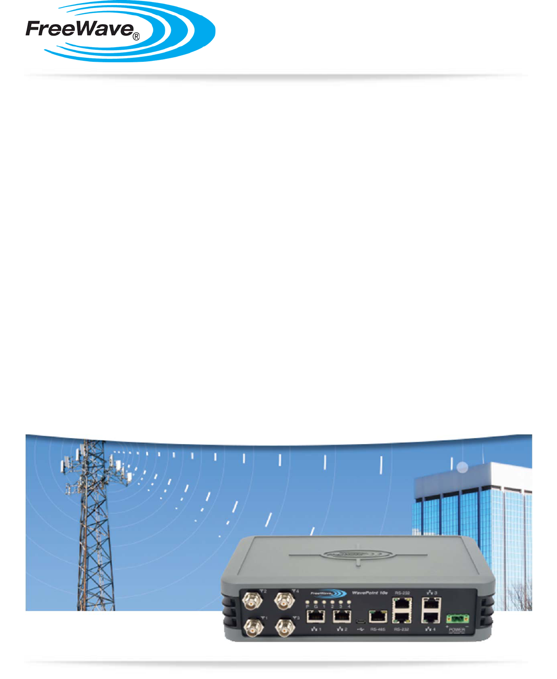
WavePoint 10e is a powerful, end-to-end wireless networking and communications platform. It
comprises a product family of networking devices to solve network infrastructure and
communications needs. The flexible WavePoint 10e platform delivers high-speed broadband data
communications across an entire network and to any environment.
WavePoint 10e provides:
l
Flexible installations on communication towers, rooftops, and street light poles with
diverse power and backhaul and antenna options.
l
Multiple applications such as voice, Internet access, video surveillance, sensory data, and
SCADA.
This chapter introduces WavePoint 10e and provides details about:

Chapte
r
1: Int
r
oduction
Page 20 of 165 LUM0063AA Rev A
This document is the property of FreeWave Technologies, Inc. and contains proprietary information owned by
FreeWave®. This document cannot be reproduced in whole or in part by any means without written permission
f
rom
FreeWave Technologies,
I
n
c.
l
Key Features and Supported Protocols on page 20
l
Requirements on page 21
l
Accessories on page 22
l
Product Variations on page 23
l
Certified Antennas on page 25
Key Features and Supported Protocols
The WavePoint 10e provides an industrial networking solution for a license-exempt market and
includes these features and standard networking technology and protocols.
Wireless Operating Modes
Configurations for the WavePoint 10e include:
l
Wireless mode: Access Point / Repeater / Client that can operate concurrently in the 900
MHz, 2.4 GHz, and 5 GHz bands.
l
Router mode: Network Address Translation (NAT) / Router / Bridge
For information about how WavePoint 10e fits into a network deployment, see Network
Deployment Scenarios on page 32.
Available Network Services
The networking services and protocols WavePoint 10e provides are:
l
Configurable MTU and PMTU discovery
when set up as an access point.
l
DHCP MAC filtering and MAC binding.
l
DHCP server or client.
l
Dynamic DNS clients.
l
Multi-instance DHCP server on WLAN.
l
Multiple LAN subnets.
Device Management
l
PPPoE, PPTP client
l
RIPv1 and RIPv2.
l
Static and dynamic IP addressing.
l
Static and dynamic routing.
l
TCP, UDP, and ICMP protocols.
l
VLAN setup.
l
VPN Tunneling and Transport.
Each WavePoint 10e is configured and monitored through a web browser interface.
The management options are:
l
Policy definition for when the WavePoint 10e is on and listening for network traffic.
l
Remote access and provisioning.

Wa
v
ePoint 10e
LUM0063AA Rev A Page 21 of 165
This document is the property of FreeWave Technologies, Inc. and contains proprietary information owned by
FreeWave®. This document cannot be reproduced in whole or in part by any means without written permission
f
rom
FreeWave Technologies,
I
n
c.
l
Logging services to monitor and track system performance using email logs, alerts, and
external
SYSLOG
servers.
l
Network Time Protocol (NTP).
l
Unlimited users definition (subject to the network capacity).
l
Over the air firmware updates.
Network Security
The security features WavePoint 10e provides to ensure the data passed through the network is
secure are:
l
Device certificates
l
Hidden, guest, and maintenance SSIDs
l
IPsec
l
MAC address filtering
l
RADIUS for authentication.
l
Rogue AP detection
l
SSL and SSH secured management
l
TCP Establish
l
VLAN-based per-SSID isolation
l
WPA, WPA2
Requirements
Important: Use the
www.freewave.com/home/WavePointLogin
site to download
the latest WavePoint 10e software. Updating the software to the latest version
provides the best experience with WavePoint 10e.
Installation Settings
Attention Network Administrator! Complete the information in this table.
SSID: _____________________________ (8-64 ASCII characters. The SSID field is case sensitive.)
Security Mode: Security Key: (This field is case sensitive.)
IP Address: Subnet Mask:
DHCP Setup Mode: Max Range:(Double the distance of the longest link in Km)

Chapte
r
1: Int
r
oduction
Page 22 of 165 LUM0063AA Rev A
This document is the property of FreeWave Technologies, Inc. and contains proprietary information owned by
FreeWave®. This document cannot be reproduced in whole or in part by any means without written permission
f
rom
FreeWave Technologies,
I
n
c.
Equipment and Configuration
This equipment and configurations are needed prior to the initial WavePoint 10e setup and
installation:
l
A computer or laptop with:
l
Windows 7 operating system.
l
A web browser to access the web pages for configuration.
l
Supported browsers include: Microsoft Internet Explorer 9 and 10, Firefox 27,
Google Chrome, Safari, and Opera.
Note:
Configuration
pages are NOT optimized for browsers on mobile devices (e.g.,
tablets, smart phones, etc.)
l
A device with wireless capability to verify the wireless connection.
l
A NEMA-4 rated enclosure (for outdoor installations only).
l
A screwdriver for attaching mounting brackets and power connector.
FreeWave Recommends: A Path Study, as applicable, for the network site.
Accessories
The items shipped in the box are:
l
The WavePoint 10e device.
l
The WavePoint 10e Quick Start Guide.
l
A CAT 5e Ethernet cable.
l
An AC power adapter.
These options are available and, if ordered, are included in the shipping box:
l
An RJ-45-to-DB9 serial cable.
l
A mounting kit.
Contact a FreeWave reseller or FreeWave Technical Support if the package is missing parts or any
parts were damaged during shipping.
Note: Antennas are shipped separately.
Wa
v
ePoint 10e
LUM0063AA Rev A Page 23 of 165
This document is the property of FreeWave Technologies, Inc. and contains proprietary information owned by
FreeWave®. This document cannot be reproduced in whole or in part by any means without written permission
f
rom
FreeWave Technologies,
I
n
c.
Product Variations
WavePoint™ has a variety of configurations offering multiple feature sets. This manual describes
these features and indicates the features that are only available on certain models.
To identify the variation and model number of the WavePoint 10e, see the product label on the back
panel.
Note: For a list of features included in each Model , see the WavePoint™ Configurations
on page 157.
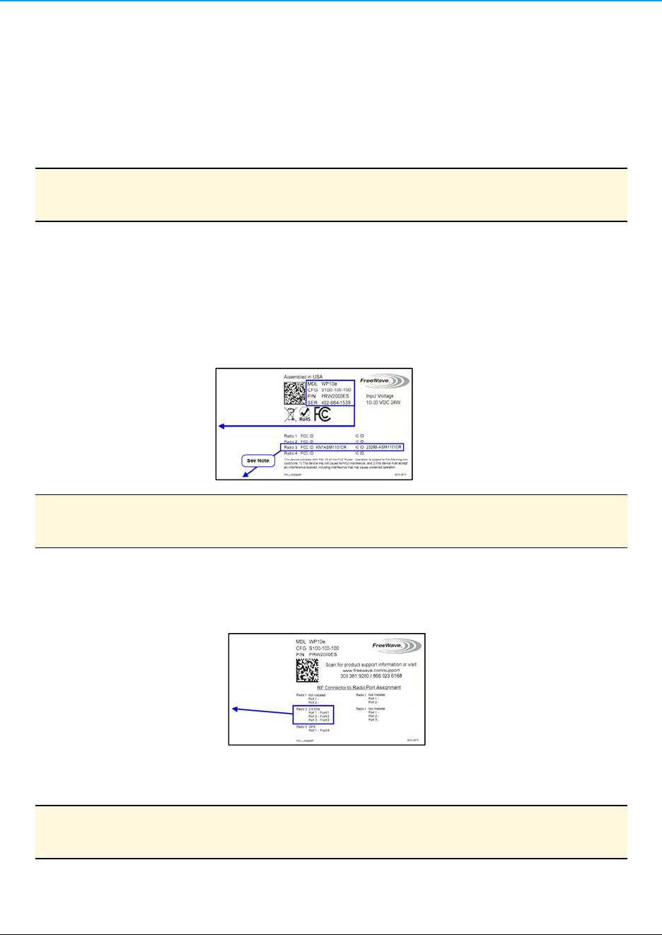
WavePoint 10e Labels
The labels on the back of the WavePoint 10e contain information about the device's port
assignments and Configuration (CFG).
Sample: Configuration Label
1. MDL - WP10e
2. CFG - S100-100-100
3. P/N - PRW2000ES
4. SER - 123-456-7890
Note: The
Configuration
label identifies the installed radios. This sample label shows
only one radio (Radio 3) installed in this WavePoint 10e device.
Sample: Port Assignment Label
1. Radio 1 - Not Installed
2. Radio 2 - Not Installed
3. Radio 3 - 2.4 GHz
a. Port 1 - Front 1
b. Port 2 - Front 2
c. Port 3 - Front 3
4. Radio 4 - Not Installed
Note: The Port Assignment label designates which RF ports (TNC connectors on the
WavePoint™ device) are used by which radio.
Chapte
r
1: Int
r
oduction
Page 24 of 165 LUM0063AA Rev A
This document is the property of FreeWave Technologies, Inc. and contains proprietary information owned by
FreeWave®. This document cannot be reproduced in whole or in part by any means without written permission
f
rom
FreeWave Technologies,
I
n
c.
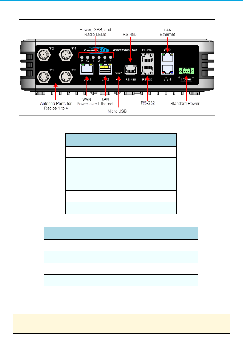
WavePoint™ Components
Data Connectors
Quantity Connector
4 RJ-45 connector for 4 Ethernet ports
3
RJ-45 connector
f
or
:
l
2 - R
S
-232
l
1 - R
S
-485
1 Micro USB connector
1 Power connector used for DC power
RF Connectors
Module Maximum Connectors
900MHz RF modules 2 TNC connectors for spatial diversity*
2.4GHz RF modules 3 TNC connectors for 3x3 MIMO operation*
5.8GHz RF modules 3 TNC connectors for 3x3 MIMO operation*
Cellular module 1 RF connector – TNC
GPS module 1 RF connector – TNC
*One active RF port is a typical configuration.
Note: Refer to the label on the WavePoint 10e to determine the exact RF Connector
configuration. A description of the labels are in WavePoint 10e Labels on page 23.

Wa
v
ePoint 10e
LUM0063AA Rev A Page 25 of 165
This document is the property of FreeWave Technologies, Inc. and contains proprietary information owned by
FreeWave®. This document cannot be reproduced in whole or in part by any means without written permission
f
rom
FreeWave Technologies,
I
n
c.
Certified Antennas
A WavePoint™ can have multiple radio modules installed, each potentially operating at different
frequencies. The model number reflects the number and frequency of the radios installed inside the
WavePoint™ device and determines the type of antennas that can be used.
Important: The use of an antenna with a higher gain or a different type of antenna
other than those approved requires new FCC approval and should not be used.
Antenna Installation Warning
Important: This section provides the required FCC warning information for working
in proximity of the WavePoint™ antennas.
1. All antenna installation and servicing must be performed by qualified technical personnel
only.
a. When servicing the antenna, or working at distances closer than those listed below,
verify the transmitter has been disabled.
b. Output is measured at the antenna terminal of the transmitter.
c. The antennas used for the WavePoint™ must be fixed-mounted on outdoor
permanent structures to provide the minimum separation distances described in this
filing for satisfying RF exposure compliance requirements.
d. When applicable, RF exposure compliance may need to be addressed at the time of
licensing, as required by the responsible FCC Bureaus, including antenna co-location
requirements of §1.1307(b)(3).
2. Typically, the antenna connected to the transmitter is a directional (high gain) antenna,
fixed-mounted on the side or top of a building, or on a tower.
a. Depending upon the application and the gain of the antenna, the total composite power
could exceed 20 watts EIRP.
b. The antenna location must only be accessible by qualified technical personnel.
c. Under normal operating conditions, no other person can touch the antenna or
approach within 3.05 meters of the antenna.
Note: These antennas have been approved for use with WavePoint 10e and the
designated Tx Streams.
900MHz Antennas
Note: Separation minimum RF safety distances are required for FCC RF exposure
compliance.

Chapte
r
1: Int
r
oduction
Page 26 of 165 LUM0063AA Rev A
This document is the property of FreeWave Technologies, Inc. and contains proprietary information owned by
FreeWave®. This document cannot be reproduced in whole or in part by any means without written permission
f
rom
FreeWave Technologies,
I
n
c.
900 MHz Antennas
Type
Antenna Model
Gain No of
Tx Streams Channel
Size
Minimum RF
Safety Distance
Omni Wavelink - PRO902-11 11dBi 2 20 MHz 94cm
Yagi Wavelink - PRO890-16 16dBi 2 20 MHz 260cm
2.4GHz Antennas
Note: Separation minimum RF safety distances are required for FCC RF exposure
compliance.
2.4GHz Antennas
Type
Antenna Model Gain No of
Tx Streams Channel
Size
Minimum RF
Safety Distance
Dipole
98618MNXX001 5dBi 3 20 MHz
40 MHz 20cm
Omni
ZDAQJ2400-12 12dBi 1 20 MHz
40 MHz 20cm
Yagi
YA240016 16dBi 1 20 MHz
40 MHz 20cm
60 degree sector RadioWaves
SEC-25V-60-17HP 17.5dBi 2 20 MHz
40 MHz 20cm
Directional Panel Superpass
SPAPG20 20.5dBi 2 20 MHz
40 MHz 25cm
Dish RadioWaves
SPD4 - 2.4NS 27dBi 3 20 MHz
40 MHz 40cm
5GHz Antennas
Note: Separation minimum RF safety distances are required for FCC RF exposure
compliance.
Wa
v
ePoint 10e
LUM0063AA Rev A Page 27 of 165
This document is the property of FreeWave Technologies, Inc. and contains proprietary information owned by
FreeWave®. This document cannot be reproduced in whole or in part by any means without written permission
f
rom
FreeWave Technologies,
I
n
c.
5GHz Antennas
Type
Antenna Model Gain No of
Tx Streams Channel
Size
Minimum RF
Safety Distance
Dipole
98618UNXX000 7dBi 1 20 MHz
40 MHz 20cm
Omni
ZDAQJ5800-12 12dBi 1 20 MHz
40 MHz 20cm
Yagi
Y5815 15dBi 1 20 MHz
40 MHz 26cm
Directional Panel RadioWaves
FP2-5-28 28.2dBi 2 20 MHz
40 MHz 71cm
Dish RadioWaves
SPD4-5.2S 34.9dBi 3 20 MHz
40 MHz 154cm
Antenna Installation
Antennas must be professionally installed on a fixed, mounted, and permanent structure to satisfy
RF exposure requirements.
Warning! Any antenna placed outdoors must be properly grounded. Use
extreme caution when installing antennas and follow ALL manufacturer
instructions included with the antenna.
Mise en garde ! Toute antenne placée à l'extérieur doit être correctement
mise à la terre. Soyez très prudent lors de l'installation d'antennes et suivre
toutes les instructions du fabricant fournies avec l'antenne.
Per FCC regulations, any antenna used with transceivers must be an approved antenna that has
comparable performance parameters.
Placement Considerations
Placement of the WavePoint 10e is likely to have a significant impact on its performance. The key to
the overall robustness of the RF link is the height and alignment of the antenna. Other antennas in
close proximity are a potential source of interference. See Diagnostics and Troubleshooting on page
149 for more information.

Chapte
r
1: Int
r
oduction
Page 28 of 165 LUM0063AA Rev A
This document is the property of FreeWave Technologies, Inc. and contains proprietary information owned by
FreeWave®. This document cannot be reproduced in whole or in part by any means without written permission
f
rom
FreeWave Technologies,
I
n
c.
FreeWave Recommends: In general, FreeWave units with a higher antenna placement have a
better communications link.
Use grid and dish antennas with low attenuation cable in lengths ranging from 3 to 100 feet.
To help optimize an antenna location, have FreeWave complete a free Path Site
study.
Contact a FreeWave sales representative for a Path Study form.
Email the completed form to pathstudy@freewave.com.
Transmit Power Settings
The Transmit Power parameter is the output power of the transceiver.
Important: The information in this section describes the FCC maximum Equivalent
Isotropically Radiated Power (EIRP) regulations.
The transceiver output power level must be set to satisfy the maximum requirements
in the country the WavePoint 10e is installed in.
The installer is responsible for ensuring that an installation is within EIRP emission
limits.
When setting up the network, consider the power gain that an antenna may add and the power loss
through cabling. Adjust the Transmit Power on the transceiver so it does NOT exceed the
maximum EIRP for the regulating body where WavePoint 10e is installed. Use the tables to
determine the correct Transmit Power parameter setting for each transceiver in the network.
When calculating the power gain, use Equation 1 to determine the total output power at the
antenna.
Transceiver Output – Losses + Antenna Gain = Output Antenna
P
ower
Equation 1
Note: Loss calculations should include cable, connectors, surge protectors, etc.
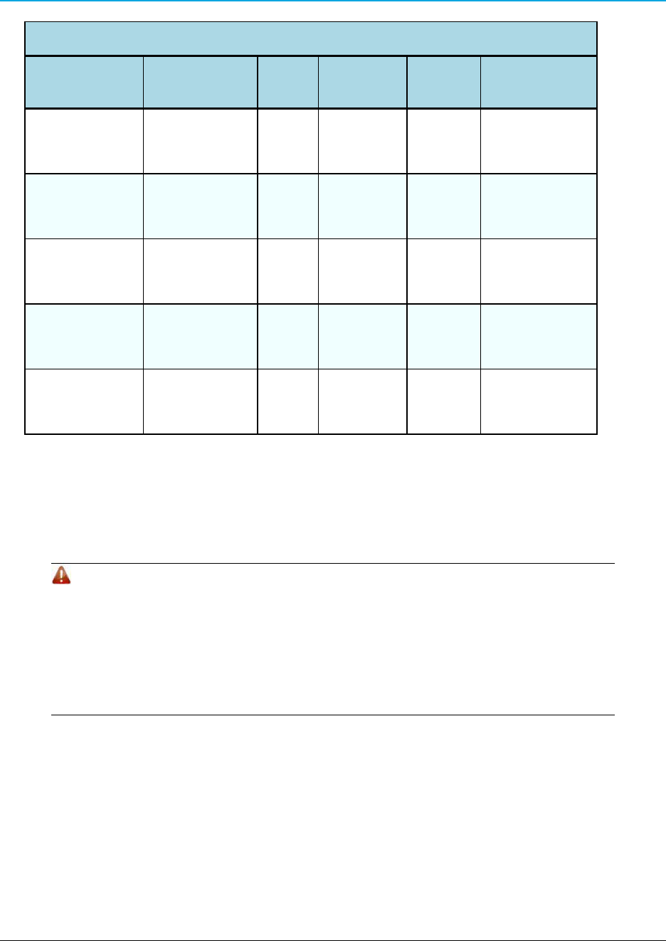
RF Loss
Cable losses for high frequency systems are one of the main losses to consider in Equation 1.
This table shows the RF loss at various cable lengths.
Example: Using the information in the table, a cable as short as 25 feet can have an
attenuation of almost 1dB.

Wa
v
ePoint 10e
LUM0063AA Rev A Page 29 of 165
This document is the property of FreeWave Technologies, Inc. and contains proprietary information owned by
FreeWave®. This document cannot be reproduced in whole or in part by any means without written permission
f
rom
FreeWave Technologies,
I
n
c.
Cable Type Attenuation
(db/100 ft)
Run Length (ft) Total Run
Attenuation (dB)
LMR400 3
.
93 25 1
.
0
LMR500 3.154 25 0
.
8
LMR600 2.518 25 0
.
6
LMR900 1.709 25 0
.
4
WavePoint™ EIRP Limits
This table provides a summary of the FCC limits for the different frequencies available in
WavePoint™.
Note: See the www.fcc.gov site for the most up-to-date information.
EIRP Limits
Frequency Band
PTP
Max EIRP
(dBm)
PTP
Max EIRP
(watts)
PTMP
Max EIRP
(dBm)
PTMP
Max EIRP
(watts)
900 ISM (902-928 MHz) 36 4 36 4
2.4 ISM (2.4 - 2.483.5
GHz)
50 158 36
4
UNII - 1 (5.15 - 5.25 GHz) 22 0
.
16 22 0
.
16
UNII - 2a (5.25 - 5.35 GHz) 29 0
.
8 29 0
.
8
UNII - 2c (5.470 - 5.725
GHz)
29 0
.
8 29
0
.
8
UNII - 3 (5.725 - 5.850
GHz)
53 200 35
3
.
2
RF Considerations for 2.4 GHz ISM Band
The FCC regulations for 2.4 GHz ISM Band are different for Point-to-Point (PTP) and Point-to-
Multi-Point (PtMP) links.
Peak Power Output
The maximum peak output power of the intentional radiator cannot exceed 1.000 Watts.

Chapte
r
1: Int
r
oduction
Page 30 of 165 LUM0063AA Rev A
This document is the property of FreeWave Technologies, Inc. and contains proprietary information owned by
FreeWave®. This document cannot be reproduced in whole or in part by any means without written permission
f
rom
FreeWave Technologies,
I
n
c.
Digital Transmission Systems (MHz) Output Limit (Watts)
2400-2483
.
5 1
.
000
Important: Point-to-Point applications operating in the 2400-2483.5 MHz band may
employ transmitting antennas with directional gain greater than 6 dBi provided the
maximum peak output power of the intentional radiator is reduced by 1 dB for every
3 dB that the directional gain of the antenna exceeds 6 dBi.
Example:
2.4 GHz with a 24 inch dish has a maximum output of 24 dBm.
2.4 GHz with a 27 inch dish has a maximum output of 23 dBm.
Point-to-Point Link
Note: The FCC permits a maximum of 36dBm EIRP when using a transmitter set to
30dBm.
However, for each 1dBm reduction in the transmitter power, the FCC permits an
increase in antenna gain of 3dBi.
Extrapolating this rule through different maximum power settings on the WavePoint™ provides
these guidelines.
Guidelines
Maximum Power
from Transmitter
Maximum Antenna
Gain (dBi)
EIRP (dBm)
30dBm 6 36
29dBm 9 38
28dBm 12 40
27dBm 15 42
26dBm 18 44
25dBm 21 46
24dBm 24 48
23dBm 27 50
22dBm 30 52

Wa
v
ePoint 10e
LUM0063AA Rev A Page 31 of 165
This document is the property of FreeWave Technologies, Inc. and contains proprietary information owned by
FreeWave®. This document cannot be reproduced in whole or in part by any means without written permission
f
rom
FreeWave Technologies,
I
n
c.
GUI Setting
(dBm)
Actual Tx Power Out
of Radio (dBm)
18 30
17 29
16 28
15 27
14 26
13 25
12 24
Note: FreeWave has certified a dish antenna with a maximum gain of 27d
B
i
.
This sets the maximum EIRP of a FreeWave system to 50 EIRP.
Dishes below 27dBi can be used with a corresponding reduction in total EIRP.
Point-to-Multi-Point Link
For Point-to-Multi-Point links, the FCC permits 1 Watt output power at the transceiver and 36dBm (4
Watts) at the antenna.
RF Considerations for 900MHz ISM Band
The 900MHz links requires these special considerations:
l
A Path Study is needed to confirm the right RF characteristics of the link.
l
The noise floor should be sampled at each site using similar antennas to the ones
expected to be deployed.
WavePoint™ GUI to Actual RF Power
This table identifies the WavePoint™ GUI settings on the Advanced Radio window and their
corresponding actual power out of the radio.
Note: Click Wireless LAN > Radios > Advanced to open the window.
GUI Setting
(dBm)
Actual Tx Power Out
of Radio (dBm)
11 23
10 22
9 21
8 20
7 19
6 18
5 17