Freemotion Fmsy99530 Owners Manual 202192
2014-07-19
: Freemotion Freemotion-Fmsy99530-Owners-Manual freemotion-fmsy99530-owners-manual freemotion pdf
Open the PDF directly: View PDF ![]() .
.
Page Count: 42
CAUTION
Read all precautions and instruc-
tions in this manual before using
this equipment. Save this manual
for future reference.
Model No. FMSY99530
Serial No.
Write the serial number in the
space above for future reference.
Serial Number Decal (Under Seat)
QUESTIONS?
As a manufacturer, we are com-
mitted to providing complete
customer satisfaction. If you
have questions, or if there are
missing or damaged parts, we
will guarantee complete satis-
faction through direct assis-
tance from our factory.
TO AVOID DELAYS, PLEASE
CALL DIRECT TO OUR TOLL-
FREE CUSTOMER HOT LINE.
The trained technicians on our
customer hot line will provide
immediate assistance, free of
charge.
CUSTOMER HOT LINE:
1-800-995-2699
Mon.–Fri., 6 a.m.–6 p.m. MST
USER’S MANUAL
Visit our website at
www.freemotionfitness.com
V

2
IMPORTANT PRECAUTIONS . . . . . . . . . . . . . . . . . . . . . . . . . . . . . . . . . . . . . . . . . . . . . . . . . . . . . . . . . . . . . . . . 3
BEFORE YOU BEGIN . . . . . . . . . . . . . . . . . . . . . . . . . . . . . . . . . . . . . . . . . . . . . . . . . . . . . . . . . . . . . . . . . . . . . . 4
ASSEMBLY . . . . . . . . . . . . . . . . . . . . . . . . . . . . . . . . . . . . . . . . . . . . . . . . . . . . . . . . . . . . . . . . . . . . . . . . . . . . . . 5
ADJUSTMENTS . . . . . . . . . . . . . . . . . . . . . . . . . . . . . . . . . . . . . . . . . . . . . . . . . . . . . . . . . . . . . . . . . . . . . . . . . . 27
WEIGHT RESISTANCE CHART . . . . . . . . . . . . . . . . . . . . . . . . . . . . . . . . . . . . . . . . . . . . . . . . . . . . . . . . . . . . . .29
CONSOLE . . . . . . . . . . . . . . . . . . . . . . . . . . . . . . . . . . . . . . . . . . . . . . . . . . . . . . . . . . . . . . . . . . . . . . . . . . . . . . .30
CABLE DIAGRAM . . . . . . . . . . . . . . . . . . . . . . . . . . . . . . . . . . . . . . . . . . . . . . . . . . . . . . . . . . . . . . . . . . . . . . . . .32
TROUBLESHOOTING AND MAINTENANCE . . . . . . . . . . . . . . . . . . . . . . . . . . . . . . . . . . . . . . . . . . . . . . . . . . .34
EXERCISE GUIDELINES . . . . . . . . . . . . . . . . . . . . . . . . . . . . . . . . . . . . . . . . . . . . . . . . . . . . . . . . . . . . . . . . . . 35
ORDERING REPLACEMENT PARTS . . . . . . . . . . . . . . . . . . . . . . . . . . . . . . . . . . . . . . . . . . . . . . . . . .Back Cover
LIMITED WARRANTY . . . . . . . . . . . . . . . . . . . . . . . . . . . . . . . . . . . . . . . . . . . . . . . . . . . . . . . . . . . . . . Back Cover
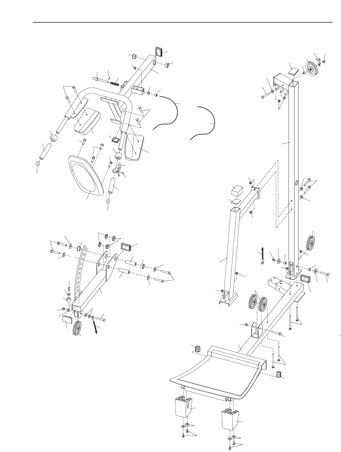
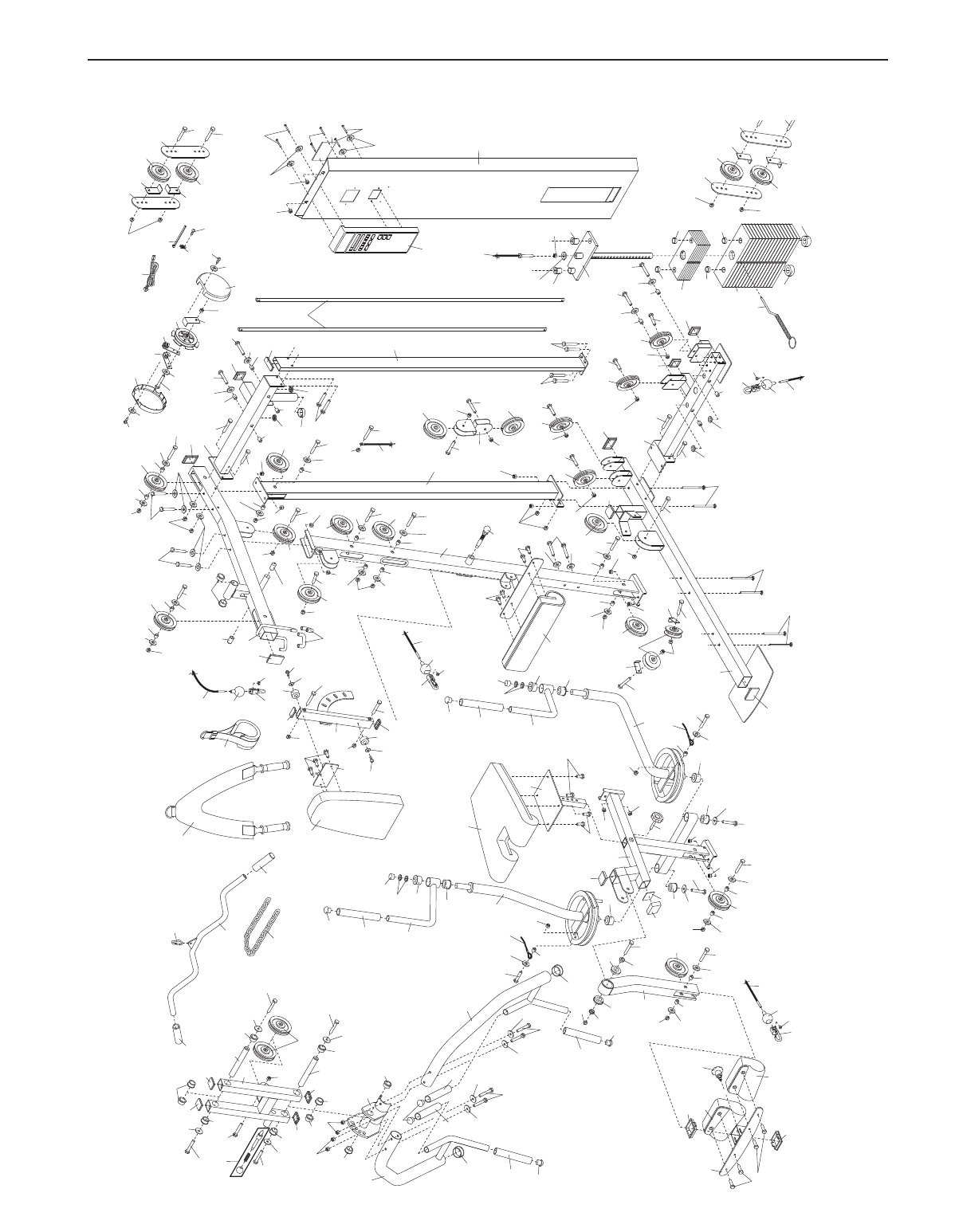
Note: A PART IDENTIFICATION CHART and a PART LIST/EXPLODED DRAWING are attached in the center of
this manual. Remove the PART IDENTIFICATION CHART and PART LIST/EXPLODED DRAWING before begin-
ning assembly.
FREEMOTION is a registered trademark of ICON IP, Inc.
TABLE OF CONTENTS
1. Read all instructions in this manual before
using the weight system. Use the weight sys-
tem only as described in this manual.
2. It is the responsibility of the owner to ensure
that all users of the weight system are ade-
quately informed of all precautions.
3. The weight system is intended for home use
only. Do not use the weight system in any
commercial, rental, or institutional setting.
4. Use the weight system only on a level sur-
face. Cover the floor beneath the weight sys-
tem to protect the floor.
5. Make sure all parts are properly tightened
each time the weight system is used.
Replace any worn parts immediately.
6. Keep children under 12 and pets away from
the weight system at all times.
7. Keep hands and feet away from moving parts.
8. Always wear athletic shoes for foot protec-
tion while exercising.
9. Make sure that the cables remain on the pul-
leys at all times. If the cables bind as you are
exercising, stop immediately and make sure
that the cables are on the pulleys.
10. Never release the press arm, butterfly arm,
leg lever, lat bar, or ab strap while the
weights are raised; the weights will fall with
great force.
11. Use only the top 20 weights with the butterfly
arms. Using the additional weights with the
butterfly arms may cause damage to the
weight system.
12. The weight system is designed to support a
maximum user weight of 300 pounds.
13. Always make sure the weight pin is fully
inserted into the weight stack before exercis-
ing.
14. Always disconnect the lat bar from the
weight system when performing an exercise
that does not use the lat bar.
15. If you feel pain or dizziness at any time while
exercising, stop immediately and begin cool-
ing down.
16. The decal shown has
been placed on the
weight system in the
location shown on page
4. If the decal is missing
or illegible, call our
Customer Service
Department toll-free at
1-800-995-2699 and order
a free replacement decal.
Apply the decal in the
location shown.
WARNING: Before beginning this or any exercise program, consult your physician. This
is especially important for persons over the age of 35 or persons with pre-existing health problems.
Read all instructions before using. ICON assumes no responsibility for personal injury or property
damage sustained by or through the use of this product.
WARNING: To reduce the risk of serious injury, read the following important precautions
before using the weight system.
IMPORTANT PRECAUTIONS
3
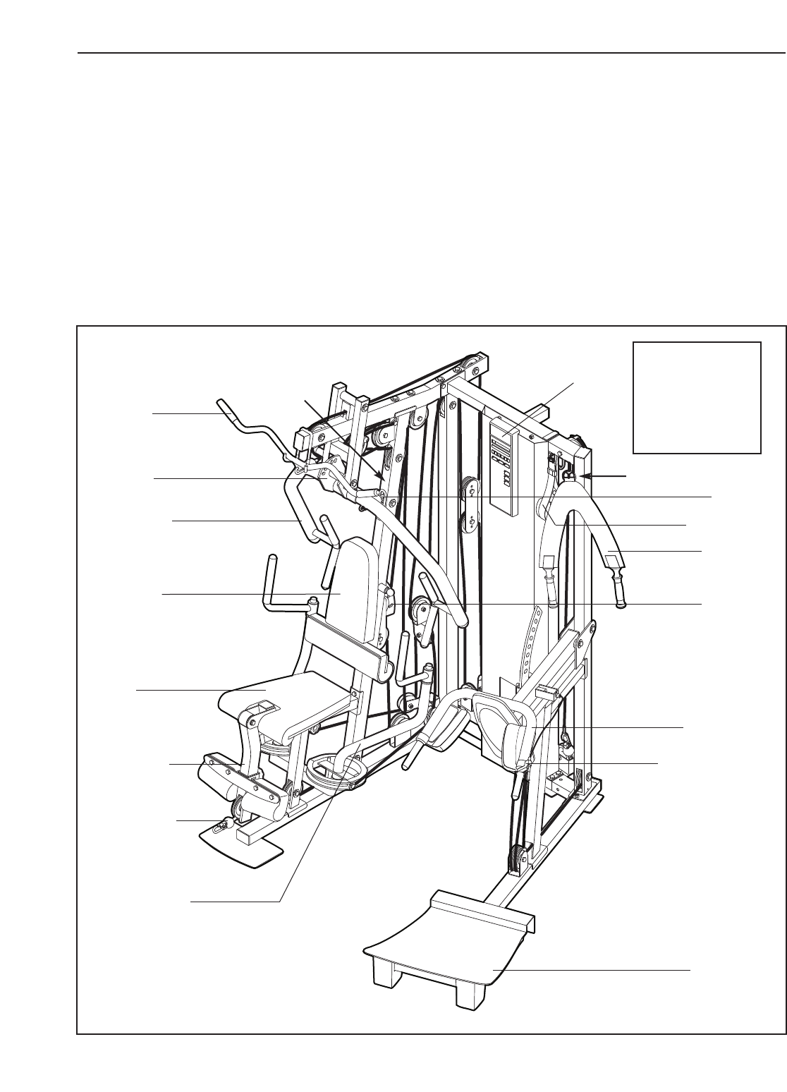
4
Press Arm
Backrest
Bracket
Release Handle
Foot Plate
Butterfly Arm
Hack Squat
Right Side
Decal
Decal
Left Side
Note: The terms “right side” and
“left side” are determined relative
to a person sitting on the seat; they
do not correspond to right and left
on the drawings in the manual.
Backrest
Low Pulley
Station
Ab Pulley
Station
Ab Strap
Ankle Strap
Console
Press Arm
Bracket
Leg Lever
Seat
Lat Bar
BEFORE YOU BEGIN
Thank you for selecting the versatile FREEMOTION®
S75 STRENGTH TRAINER weight system. The weight
system offers a selection of weight stations designed
to develop every major muscle group of the body.
Whether your goal is to tone your body, build dramatic
muscle size and strength, or improve your cardiovas-
cular system, the weight system will help you to
achieve the specific results you want.
For your benefit, read this manual carefully before
using the weight system. If you have additional ques-
tions, please call our Customer Service Department toll-
free at 1-800-995-2699, Monday through Friday, 6 a.m.
until 6 p.m. Mountain Time (excluding holidays). To help
us assist you, please note the product model number
and serial number before calling. The model number is
FMSY99530. The serial number can be found on a
decal attached to the weight system (see the front cover
of this manual).
Before reading further, please review the drawing below
and familiarize yourself with the parts that are labeled.
ASSEMBLED
DIMENSIONS:
Height: 84 in.
Width: 86 in.
Length: 72 in.

5
Make sure you have the following tools:
• Two adjustable wrenches
• One standard screwdriver
• One phillips screwdriver
• One rubber mallet
• You will also need grease or petroleum jelly, a
small amount of soapy water, and clear tape or
masking tape.
Note: Assembly will be more convenient if you have
a socket set, a set of open-end or closed-end
wrenches, or a set of ratchet wrenches.
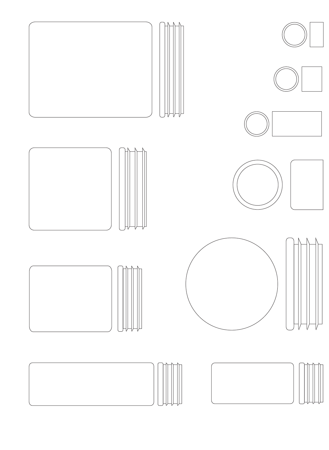
How to Identify Parts
To help you identify the small parts used in assembly,
we have included a PARTIDENTIFICATION CHART
in the center of this manual. Place the chart on the
floor and use it to easily identify parts during each
assembly step. Note: Some small parts may have
been pre-attached. If a part is not in the parts
bag, check to see if it has been pre-attached.
How to Orient Parts
As you assemble the weight system, make sure that
all parts are oriented exactly as shown in the draw-
ings.
Tightening Parts
Tighten all parts as you assemble them, unless
instructed to do otherwise.
Questions?
If you have questions after reading the assembly
instructions, please call our Customer Service
Department at 1-800-995-2699.
Assembly Requires Two Persons
For your convenience and safety, assemble the
weight system with the help of another person.
Set Aside Enough Time
Due to the many features of the weight system, the
assembly process will take a several hours. By set-
ting aside plenty of time and by deciding to make
the task enjoyable, assembly will go smoothly. You
may want to assemble the weight system over a
couple of evenings.
Select a Location for the Weight System
Because of its weight and size, the weight system
should be assembled in the location where it will be
used. Make sure that there is enough room to walk
around the weight system as you assemble it.
How to Unpack the Box
To make assembly as easy as possible, we have
divided the assembly process into four stages. The
parts needed for each stage are found in individual
bags. Important: Wait until you begin each stage
to open the parts bag for that stage. Place all
parts of the weight system in a cleared area and
remove the packing materials. Do not dispose of
the packing materials until assembly is completed.
Make Assembly Easier for Yourself
Everything in this manual is designed to
ensure that the weight system can be assem-
bled successfully by anyone. Before begin-
ning assembly, make sure to read the
information on this page. This brief intro-
duction will save you much more time than
it takes to read it.
The Four Stages of the Assembly Process
Frame Assembly—You will begin by assembling
the base and the uprights that form the skeleton of
the weight system.
Arm Assembly—During this stage you will
assemble the arms and the leg lever.
Cable Assembly—During this stage you will
attach the cables and pulleys that connect the
arms to the weights.
Seat Assembly—During the final stage you will
assemble the seats and the backrests.
ASSEMBLY
6
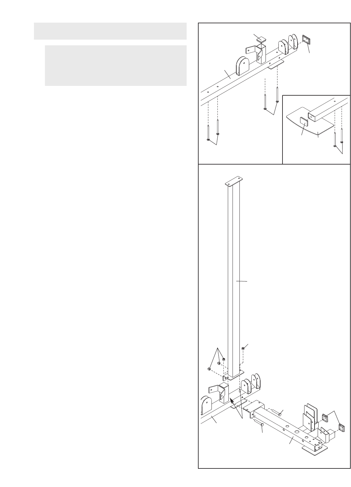
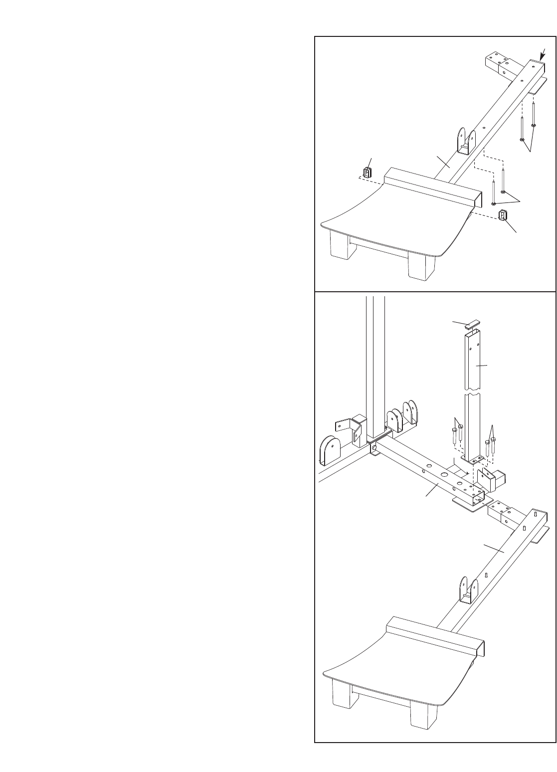
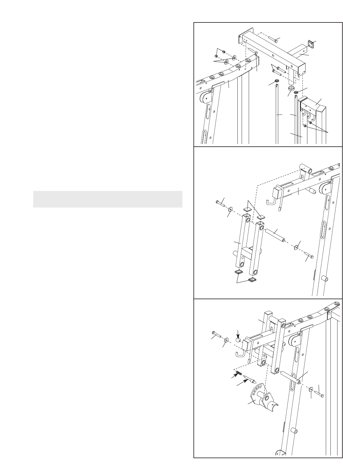
1.
Locate and open the parts bag labeled
“FRAME ASSEMBLY.”
Press a 50mm Square Inner Cap (61) and two
50mm x 75mm Inner Caps (53) into the Press
Base (1).
Insert four M10 x 68mm Carriage Bolts (104) and
two M10 x 74mm Carriage Bolts (102) up through
the bottom of the Press Base (1). Place the Press
Base flat on the floor. Note: If the Bolts fall out,
stick a piece of tape over the bolt heads to
hold them in place.
2. Press two 50mm Square Inner Caps (61) into the
extensions on the Rear Base (2).
Attach the Rear Base (2) and the Right Rear
Upright (8) to the Press Base (1) with the indicat-
ed pair of M10 x 74mm Carriage Bolts (102), two
M10 x 100mm Bolts (128), and four M10 Nylon
Locknuts (123). Do not tighten the Locknuts
yet.
Before beginning assembly, make sure you
have read and understood the information
on page 5. This brief introduction will save
you much more time than it takes to read it!
Frame Assembly 1
53
61
53
104
1
1
8
123
102
123
128 61
2
1
128
102
2
104
7
3. Press two 25mm x 50mm Inner Caps (101) and a
50mm x 75mm Inner Cap (53) into the Hack
Squat Base (3).
Insert four M10 x 68mm Carriage Bolts (104) up
through the Hack Squat Base (3). Place the Base
flat on the floor. Note: If the Bolts fall out, stick
a piece of tape over the bolt heads to hold
them in place.
4. Press a 26mm x 76mm Inner Cap (62) into the
Left Rear Upright (7).
Insert the Hack Squat Base (3) into the Rear
Base (2).
Attach the Hack Squat Base (3) and the Left Rear
Upright (7) to the Rear Base (2) with four M10 x
25mm Bolts (106). Do not tighten the Bolts yet.
3
4
3
104
101
101
53
104
62
7
2
106 106
3
8
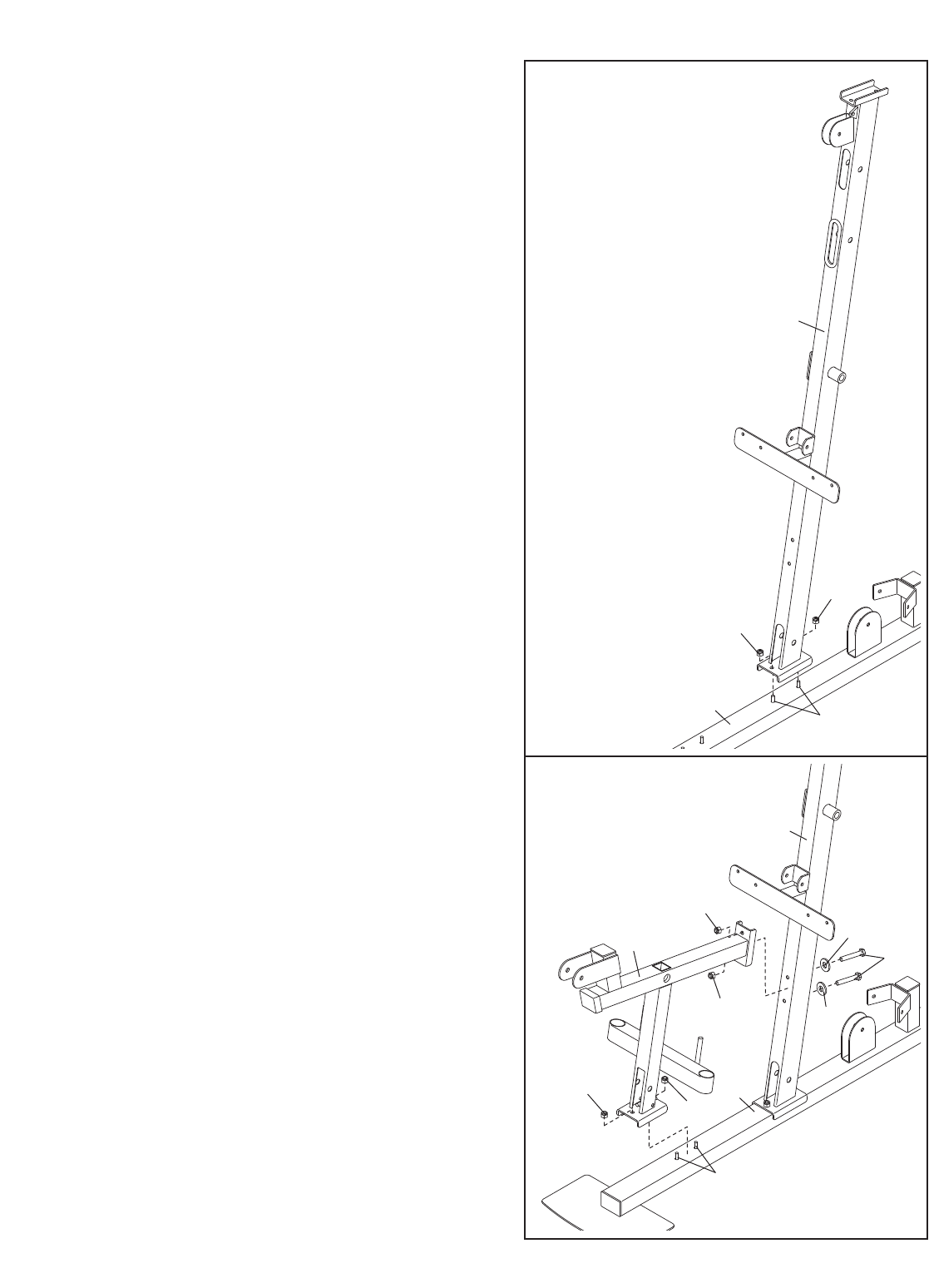
5. Attach the Front Upright (9) to the Press Base (1)
with the indicated two M10 x 68mm Carriage
Bolts (104) and two M10 Nylon Locknuts (123).
Do not tighten the Locknuts yet.
6. Attach the Seat Frame (10) to the Press Base (1)
with the indicated two M10 x 68mm Carriage
Bolts (104) and two M10 Nylon Locknuts (123).
Do not tighten the Locknuts yet.
Attach the Seat Frame (10) to the Front Upright
(9) with two M10 x 95mm Bolts (105), two M10
Washers (118), and M10 Nylon Locknuts (123).
Do not tighten the Locknuts yet.
5
6
104
1
9
123
123
104
1
123
123
123
123
118
118
10 105
9
9
7. Press a 50mm x 75mm Inner Cap (53) into the
top of the Hack Squat Upright (6).
Attach the Hack Squat Upright (6) to the Hack
Squat Base (3) with the indicated pair of M10 x
68mm Carriage Bolts (104) and two M10 Nylon
Locknuts (123). Do not tighten the Locknuts
yet.
8. Attach the Hack Squat Leg (4) to the Hack Squat
Base (3) with the indicated pair of M10 x 68mm
Carriage Bolts (104) and two M10 Nylon Locknuts
(123). Do not tighten the Locknuts yet.
Attach the Hack Squat Leg (4) to the Hack Squat
Upright (6) with two M10 x 95mm Bolts (105), two
M10 Washers (118), and two M10 Nylon Locknuts
(123). Do not tighten the Locknuts yet.
7
8
6
123
123
3
104
53
6
123
123
118
105
4
3
123 123
104
10
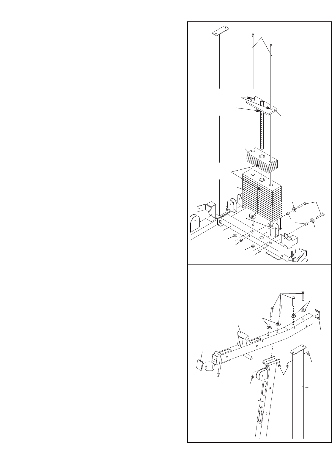
9. Press two Inner Bushings (88) into the Rear Base
(2). Set the two Weight Guides (25) in the indicat-
ed holes in the Rear Base.
Attach the Weight Guides (25) to the Rear Base
(2) with two M8 x 90mm Bolts (130), two M8
Washers (124), and four 15mm x 30mm Spacers
(87).
Slide two Weight Bumpers (89) onto the Weight
Guides (25). Make sure the large hole faces
down.
Slide the sixteen Large Weights (28), the seven
Small Weights (27) onto the Weights Guides (25).
Make sure the numbers are on the indicated
side and are in order.
Grease the indicated holes in the Top Weight
(26). Slide the Top Weight onto the Weight
Guides (25). Make sure the number is in the
indicated position.
9
10
25
26
27
Numbers
2
89
88
87
87
87
124
124
130
88
28
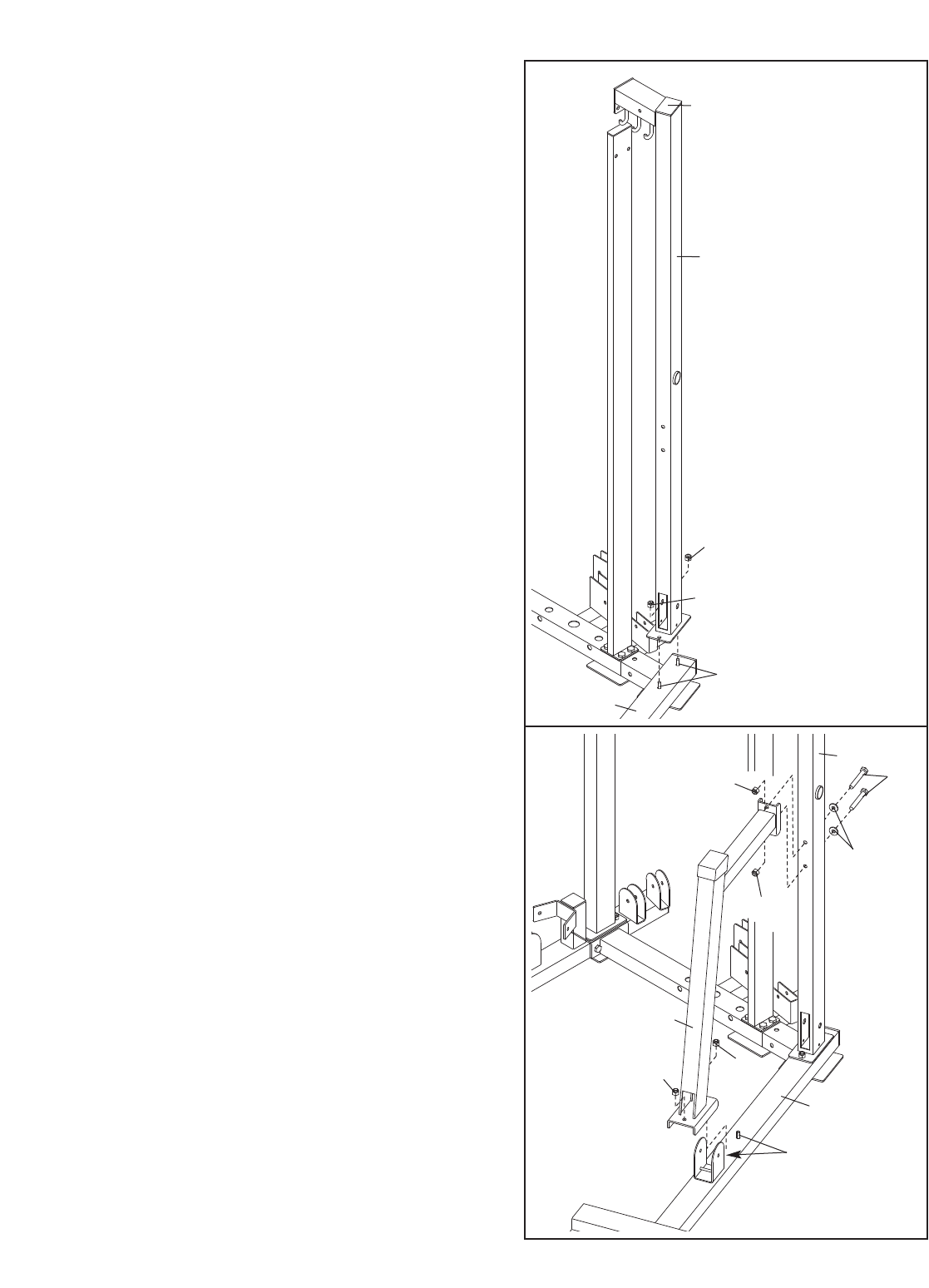
10. Press two 50mm x 75mm Inner Caps (53) into
the ends of the Press Top Frame (11).
Attach the Press Top Frame (11) to the Front
Upright (9) and the Right Rear Upright (8) with
four M10 x 95mm Bolts (105), four M10 Washers
(118), and four M10 Nylon Locknuts (123). Do
not tighten the Locknuts yet.
105
118
118
53
11
53
123
123
123 8
9
Grease
Number
11
11. Press a 50mm Square Inner Cap (61) and two
Inner Bushings (88) into the Rear Top Frame (12).
Press a 25mm Round Outer Cap (65) onto the
Rear Top Frame. Set the Rear Top Frame onto the
two Weight Guides (25).
Attach the Rear Top Frame (12) to the Press Top
Frame (11) with two M10 x 70mm Bolts (114), two
M10 Washers (118), and two M10 Nylon Locknuts
(123). Do not tighten the Locknuts yet.
Attach the Rear Top Frame (12) to the Left Rear
Upright (7) and Hack Squat Upright (6) with two
M10 x 50mm Bolts (111) and two M10 Nylon
Locknuts (123). Do not tighten the Locknuts yet.
Tighten the M10 Nylon Locknuts (123) used in
steps 2–11, and the M10 x 25mm Bolts (106)
used in step 4.
Note: The remaining hardware from the parts
bag will be used in step 63.
11
12
12. Locate and open the parts bag labeled “ARM
ASSEMBLY.”
Press four 40mm x 50mm Inner Caps (60) into
the Press Frame (22)
Attach the Press Frame (22) to the Press Top
Frame (11) with a Long Pivot Rod (45), two M10
Large Washers (122), and two M10 x 25mm Bolts
(106).
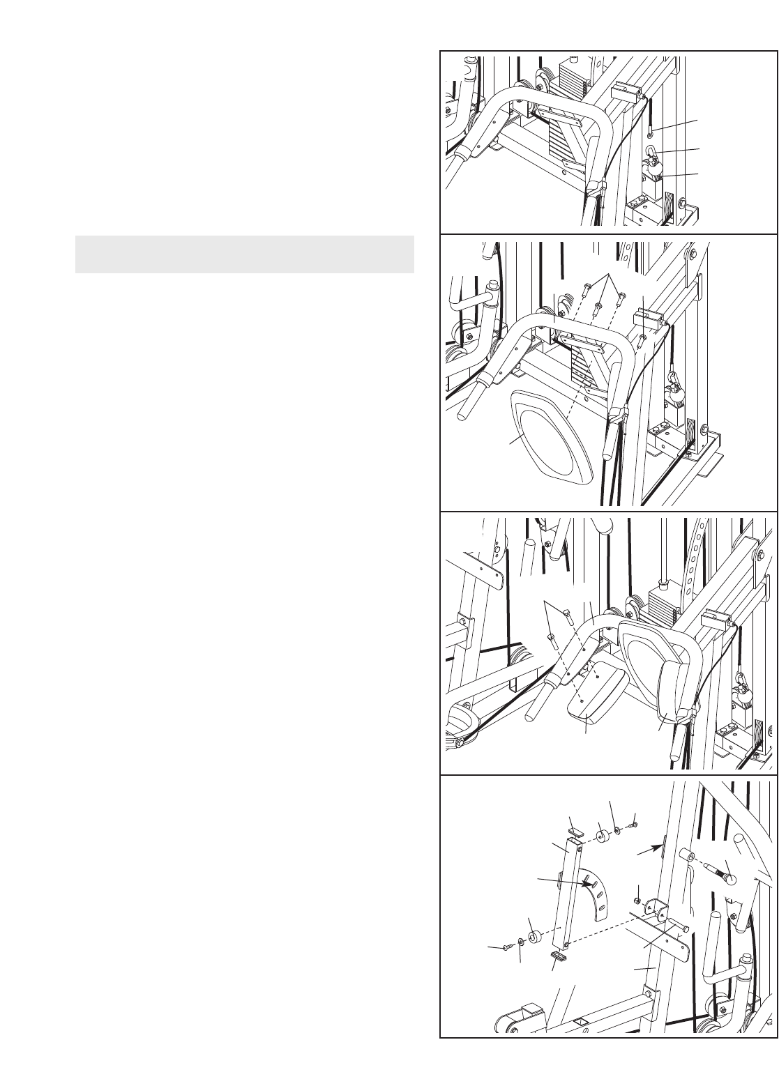
13. Note: The Press Knob (78) must be disassem-
bled for this step. Insert the pop pin through the
spring and the Press Frame (22). Tighten the
knob onto the pop pin. Make sure the knob is
fully tightened.
Have a second person pull the Press Knob (78)
out as far as it can go. Slide a Long Pivot Rod
(45) through the Press Frame (22) and the Press
Bracket (21). Engage the Press Knob into a hole
in the Bracket.
Tighten two M10 x 25mm Bolts (106) and two
M10 Large Washers (122) into the Long Pivot
Rod (45).
Arm Assembly
13
123
114
111
6
123
11
65
7
12
25
88 88
114 61
118
45
11
122
122
22
106
106 60
60
21
45
Spring
Pop Pin
Knob
22
106
106
122
122
65
119
12
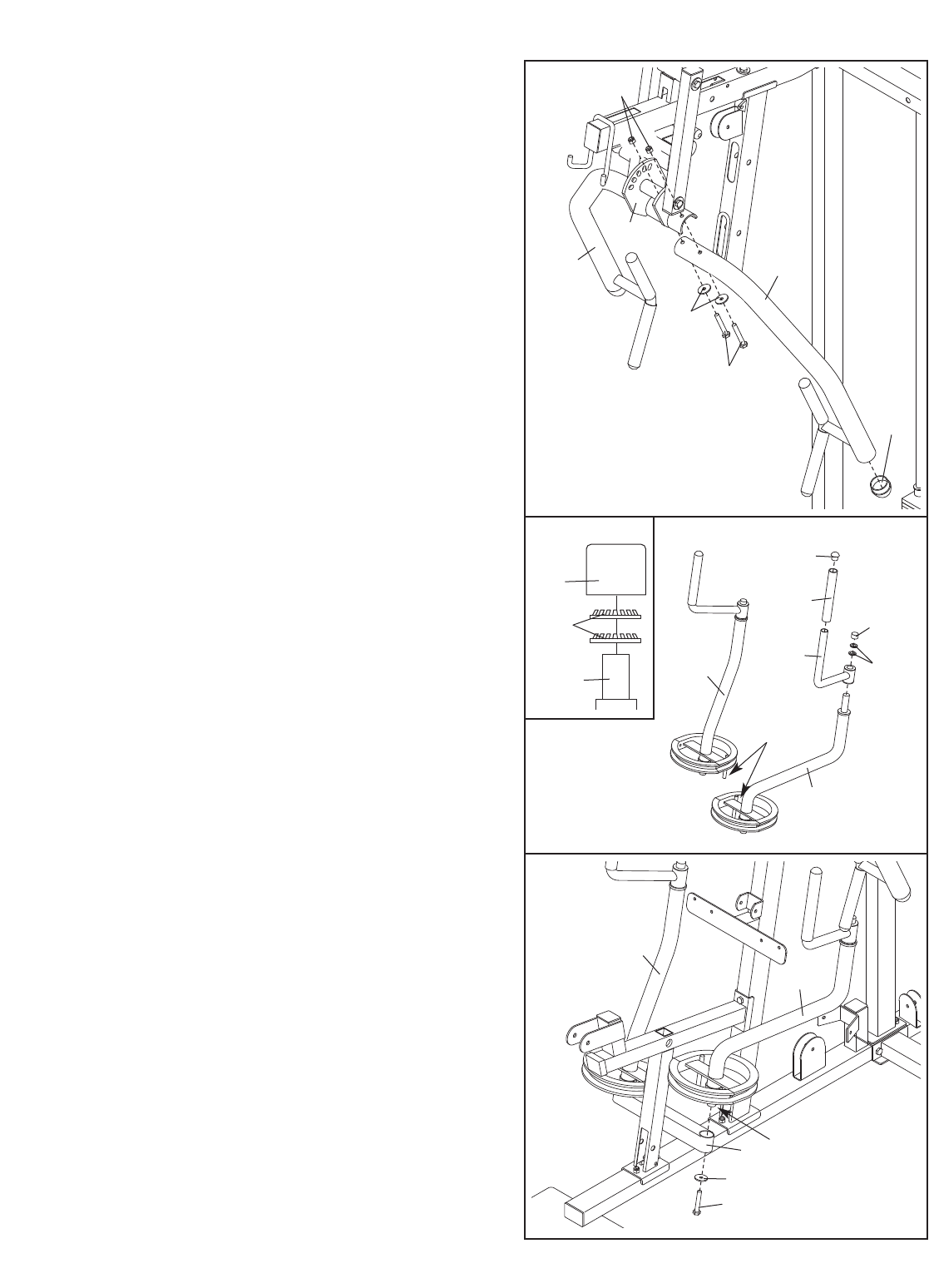
15. Slide a Butterfly Handgrip (43) onto a Butterfly
Handle (18). Press a 25mm Round Inner Cap
(58) into the Handle.
Identify the Left and Right Butterfly Arms (16,
17) by the location of the rods.
Slide the Butterfly Handle (18) onto the Left
Butterfly Arm (16). Place two 25mm Retainers
(119) under a 25mm Round Outer Cap (65), as
shown in the inset drawing. Make sure the teeth
on the Retainers bend toward the Cap. Tap the
Cap and Retainers onto the Butterfly Arm.
Attach the other Butterfly Handle (18) to the
Right Butterfly Arm (17) in the same manner.
16. Use an included grease packet to grease the axle
on the Left Butterfly Am (16). Attach the Left
Butterfly Arm to the Seat Frame (10) with an M10
x 25mm Bolt (106) and an M10 Large Washer
(122).
Attach the Right Butterfly Arm (17) in the
same manner.
14. Press a 56mm Round Inner Cap (56) into the end
of the Left Press Arm (19).
Orient the Left Press Arm (19) as shown. Attach
the Arm to the Press Bracket (21) with two M10 x
78mm Bolts (108), two M10 Washers (118), and
two M10 Nylon Locknuts (123).
Repeat this step with the Right Press Arm
(20).
14
15
16
21
20
123
56
108
118
19
43 65
119
17
16
16
18
Rod
16
58
106
10
122
Grease
17
13
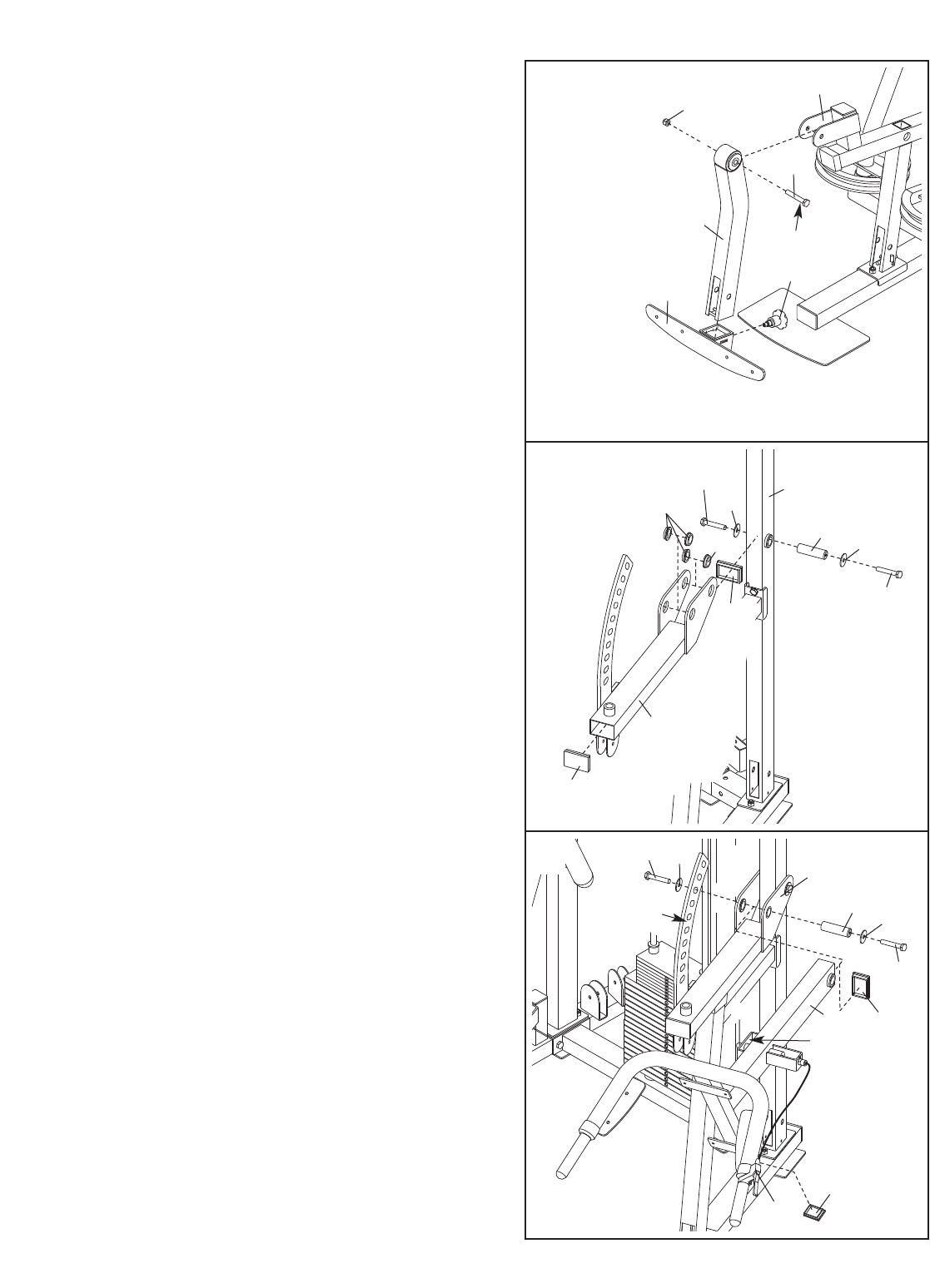
18. Press two 50mm x 75mm Inner Caps (53) and
four Small Support Bushings (38) into the Hack
Squat Bracket (5).
Attach the Hack Squat Bracket (5) to the Hack
Squat Upright (6) with a Short Pivot Rod (46), two
M10 Large Washers (122), and two M10 x 25mm
Bolts (106).
17. Attach the Pad Frame Knob (79) to the Leg Lever
(15). Make sure the Knob is fully tightened.
Pull the knob on the Pad Frame Knob (79) out
and slide the Pad Frame (23) onto the Leg Lever
(15). Engage the knob into a hole in the Leg
Lever.
Grease the M12 x 78mm Bolt (146). Attach the
Leg Lever (15) to the Seat Frame (10) with the
Bolt and an M12 Nylon Locknut (151). Do not
overtighten the Locknut; the Leg Lever must
be able to pivot easily.
17
18
19. Press a 50mm x 75mm Inner Cap (53) and a
40mm x 50mm Inner Cap (60) into the Hack
Squat Frame (31).
Squeeze the Release Handle (69) and slide the
guide on the Hack Squat Frame (31) over the
arm on the Hack Squat Bracket (5). Let go of the
Release Handle so that the Release Pin (75)
engages the arm.
Attach the Hack Squat Frame (31) to the Hack
Squat Bracket (5) with a Short Pivot Rod (46),
two M10 Large Washers (122), and two M10 x
25mm Bolts (106).
19
15
10
23
79
151
Grease
146
6
38
38 46 122
122
106
106
5
53
53
122
122
106
Arm
106
31
69
60
75
Guide
46
5
53
14
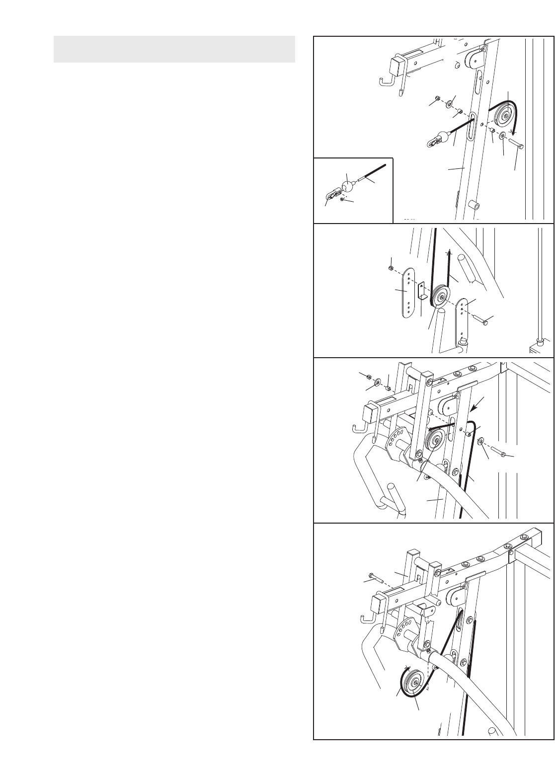
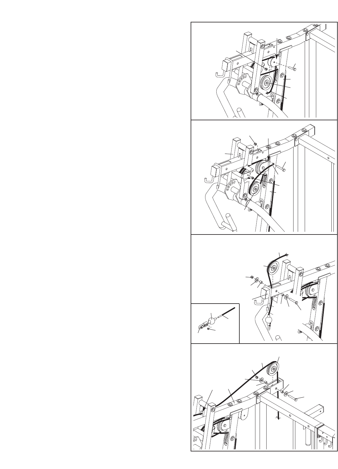
20. Locate and open the parts bag labeled
“CABLE ASSEMBLY.”
Refer to the CABLE DIAGRAMS on pages 32
and 33 to identify the cables. Do not overtight-
en the locknuts used to attach the pulleys; the
pulleys must be able to pivot easily.
Locate the Ab Cable (70). Slide a Cable Ball
(82) onto the end of the Cable. Hold an M8 Nylon
Locknut (134) inside a Clip End (83), and insert
the Cable into the Clip End and Locknut. Insert a
screwdriver between the Locknut and the Clip
End. Rotate the screwdriver, Clip End, and
Locknut together until two threads of the Cable
show past the Locknut.
Route the end of the Cable without the ball
through the indicated hole in the Front Upright (9)
and over a 115mm Pulley (47).
Attach the 115mm Pulley (47) inside the Front
Upright (9) with an M10 x 67mm Bolt (109), two
M10 Washers (118), two 15mm x 12mm Spacers
(86), and an M10 Nylon Locknut (123).
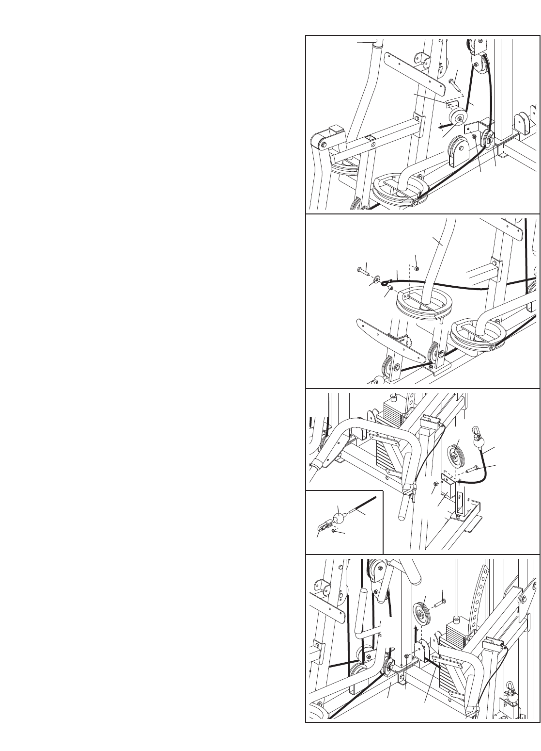
21. Wrap the Ab Cable (70) under a 115mm Pulley
(47). Attach the Pulley and a Cable Trap (66) to
the top set of holes in two Pulley Plates (50) with
an M10 x 50mm Bolt (111) and an M10 Nylon
Locknut (123). Make sure the Cable Trap is
turned to hold the Cable in the groove of the
Pulley.
22. Route the Ab Cable (70) over a 115mm Pulley
(47) and through the Front Upright (9). Make
sure the Cable is under the rod in the Upright.
Attach the Pulley inside the Upright with an M10 x
67mm Bolt (109), two M10 Washers (118), two
15mm x 12mm Spacers (86), and an M10 Nylon
Locknut (123).
23. Wrap the Ab Cable (70) under a 115mm Pulley
(47). Attach the Pulley to the bracket on the Press
Frame (22) with an M10 x 70mm Bolt (114). Do
not thread a locknut onto the Bolt yet.
20
21
22
23
70
9
86
86
118
118
109
47
123
50 50
66
70
47
111
123
22
114
47
70
9
86
86
118
Rod
118
109
47
123
Cable Assembly
70
134
83
82
70
15
25. Wrap the Ab Cable (70) under a 115mm Pulley
(47). Attach the Pulley to the bracket on the Press
Frame (22) with the M10 x 70mm Bolt (not shown)
used in step 23 and an M10 Nylon Locknut (123).
Attach the end of the Ab Cable (70) to the indicat-
ed bracket on the Front Upright (9) with an M8 x
23mm Shoulder Bolt (152) and an M8 Nylon
Locknut (134).
26. Locate the High Cable (81). Slide a Cable Ball
(82) onto the end of the Cable. Hold an M8 Nylon
Locknut (134) inside a Clip End (83), and insert
the Cable into the Clip End and Locknut. Insert a
screwdriver between the Locknut and the Clip
End. Rotate the screwdriver, Clip End, and
Locknut together until two threads of the Cable
show past the Locknut.
Route the other end of the High Cable (81) up
through the Press Top Frame (11).
Wrap the High Cable (81) over a 115mm Pulley
(47). Attach the Pulley inside the Press Top
Frame (11) with an M10 x 67mm Bolt (109), two
M10 Washers (118), two 15mm x 12mm Spacers
(86), and an M10 Nylon Locknut (123).
27. Route the High Cable (81) through the indicated
slot in the Press Top Frame (11), over a 115mm
Pulley (47), and down through the Press Top
Frame. Attach the Pulley inside the Press Top
Frame with an M10 x 67mm Bolt (109), two M10
Washers (118), two 15mm x 12mm Spacers (86),
and an M10 Nylon Locknut (123).
24. Wrap the Ab Cable (70) over a 115mm Pulley
(47). Attach the Pulley to the bracket on the Front
Upright (9) with an M10 x 45mm Bolt (110) and
an M10 Nylon Locknut (123).
24
25
26
27
123
9
70
47
Bracket
110
134
22
Bracket
152
123
70
47
9
47
11
118
123
118 109
86
86
81
109
118
118
11
Slot
81
47
86 86
123
81
134
83
82
16
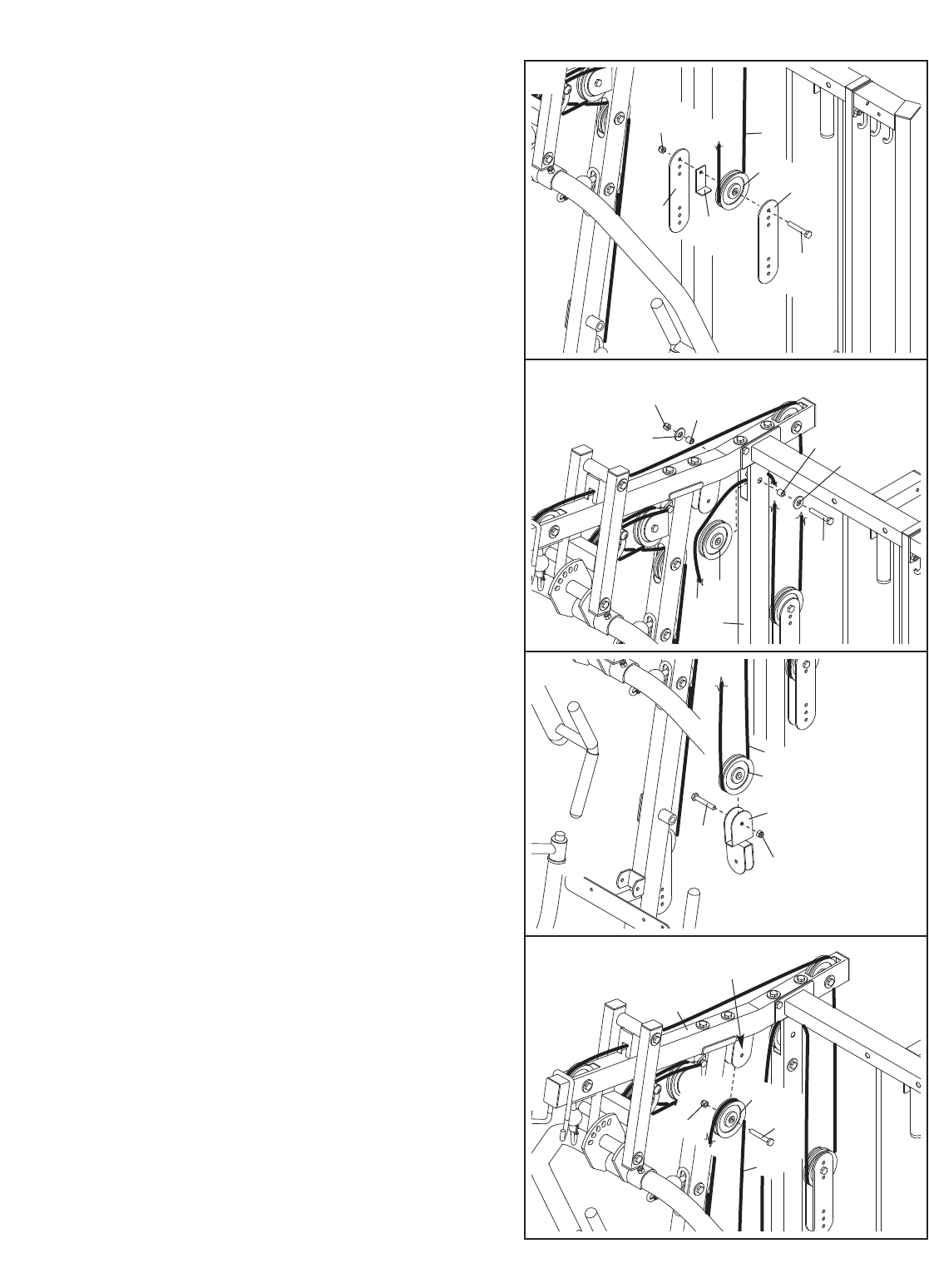
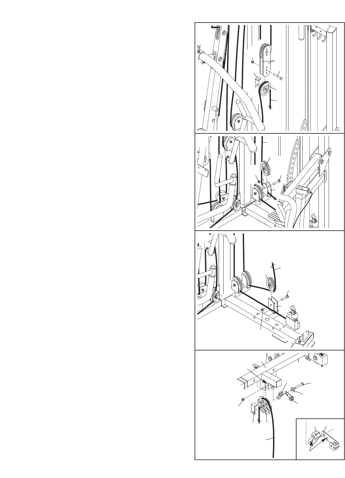
29. Route the High Cable (81) through the Right Rear
Upright (8) and over a 115mm Pulley (47). Attach
the Pulley inside the Upright with an M10 x 67mm
Bolt (109), two M10 Washers (118), two 15mm x
12mm Spacers (86), and an M10 Nylon Locknut
(123).
30. Wrap the High Cable (81) under a 115mm Pulley
(47). Attach the Pulley to the Double “U”-bracket
(147) with an M10 x 45mm Bolt (110) and an M10
Nylon Locknut (123).
28. Wrap the High Cable (81) under a 115mm Pulley
(47). Attach the Pulley and a Cable Trap (66) to
the top set of holes in the other pair of Pulley
Plates (50) with an M10 x 50mm Bolt (111) and
an M10 Nylon Locknut (123). Make sure the
Cable Trap is turned to hold the Cable in the
groove of the Pulley.
28
29
30
31. Wrap the High Cable (81) over a 115mm Pulley
(47). Attach the Pulley to the bracket on the Press
Top Frame (11) with an M10 x 45mm Bolt (110)
and an M10 Nylon Locknut (123).
31
123
50
50
66
47
86
86
81
123
118
118
109
8
47
81
111
123
81
47
110
147
11
81
47
123 110
Bracket
17
33. Wrap the High Cable (81) over a 115mm Pulley
(47). Attach the Pulley and a Cable Trap (66) to
the second set of holes from the bottom of the
indicated pair of Pulley Plates (50) with an M10 x
50mm Bolt (111) and an M10 Nylon Locknut
(123). Make sure the Cable Trap is turned to
hold the Cable in the groove of the Pulley.
34. Route the High Cable (81) through the Front
Upright (9) and under a 115mm Pulley (47).
Attach the Pulley inside the Front Upright with an
M10 x 67mm Bolt (109), two M10 Washers (118),
two 15mm x 12mm Spacers (86), and an M10
Nylon Locknut (123).
32. Wrap the High Cable (81) under a 115mm Pulley
(47). Attach the Pulley to the bracket on the Press
Base (1) with an M10 x 45mm Bolt (110) and an
M10 Nylon Locknut (123).
32
33
34
35. Route the High Cable (81) through the Seat
Frame (10) and under a 115mm Pulley (47).
Attach the Pulley inside the Seat Frame with an
M10 x 67mm Bolt (109), two M10 Washers (118),
two 15mm x 12mm Spacers (86), and an M10
Nylon Locknut (123).
35
47
81
1110
123
123
111
50
47
66
81
118
109
118
86
86
123 9
81
47
81
86
86
123
118
109
118
47
10
18
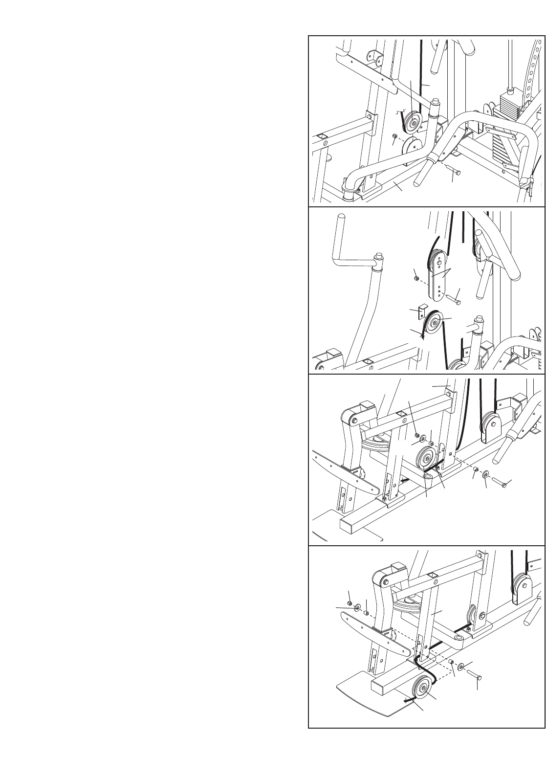
38. Wrap the Butterfly Cable (39) under a 115mm
Pulley (47). Attach the Pulley and a Cable Trap
(66) to the indicated bracket on the Press Base
(1) with an M10 x 45mm Bolt (110) and an M10
Nylon Locknut (123). Make sure the Cable Trap
is turned to hold the Cable in the groove of
the Pulley.
39. Wrap the Butterfly Cable (39) over a 115mm
Pulley (47). Attach the Pulley to the bottom of the
Double “U”-bracket (147) with an M10 x 45mm
Bolt (110) and an M10 Nylon Locknut (123).
36. Route the High Cable (81) through the Leg Lever
(15) and under a 115mm Pulley (47). Make sure
the Cable is over the rod in the Leg Lever.
Attach the Pulley inside the Leg Lever with an
M10 x 67mm Bolt (109), two M10 Washers (118),
two 15mm x 12mm Spacers (86), and an M10
Nylon Locknut (123).
Slide a Cable Ball (82) onto the end of the High
Cable (81). Hold an M8 Nylon Locknut (134)
inside a Clip End (83), and insert the Cable into
the Clip End and Locknut. Insert a screwdriver
between the Locknut and the Clip End. Rotate the
screwdriver, Clip End, and Locknut together until
two threads of the Cable show past the Locknut.
37. Locate the Butterfly Cable (39). Attach one end
of the Cable to the Left Butterfly Arm (16) with an
M10 x 40mm Bolt (148), an M10 Washer (118), a
15mm x 12mm Spacer (86), and an M10 Nylon
Locknut (123). Make sure the loop on the Cable
is over the Spacer.
36
37
38
39
109
118
118
86
15
47
86
123
81 Rod
86
123
118
39 148
47
66
39
110
123
1
123
39
147
110
47
16
81
134
83
82
19
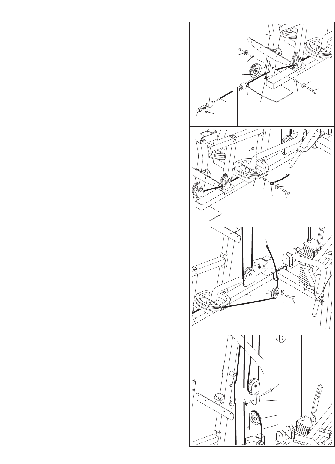
40. Wrap the Butterfly Cable (39) under a 115mm
Pulley (47). Attach the Pulley and a Cable Trap
(66) to the indicated bracket on the Press Base
(1) with an M10 x 45mm Bolt (110) and an M10
Nylon Locknut (123). Make sure the Cable Trap
is turned to hold the Cable in the groove of
the Pulley.
42. Locate the Low Cable (71). Slide a Cable Ball
(82) onto the end of the Cable. Hold an M8 Nylon
Locknut (134) inside a Clip End (83), and insert
the Cable into the Clip End and Locknut. Insert a
screwdriver between the Locknut and the Clip
End. Rotate the screwdriver, Clip End, and
Locknut together until two threads of the Cable
show past the Locknut.
Route the Low Cable (71) under a 115mm Pulley
(47). Attach the Pulley to the indicated bracket on
the Rear Base (2) with an M10 x 45mm Bolt (110)
and an M10 Nylon Locknut (123).
43. Wrap the Low Cable (71) under a 115mm Pulley
(47). Attach the Pulley to the indicated bracket on
the Press Base (1) with an M10 x 45mm Bolt
(110) and an M10 Nylon Locknut (123).
41. Attach the end of the Butterfly Cable (39) to the
Right Butterfly Arm (17) with an M10 x 40mm Bolt
(148), an M10 Washer (118), a 15mm x 12mm
Spacer (86), and an M10 Nylon Locknut (123).
Make sure the loop on the Cable is over the
Spacer.
40
41
42
43
66
47
39
123 1
110
39
123
17
86
118
148
123
2
47
110
71
123
1
47
71
110
71
134
83
82
20
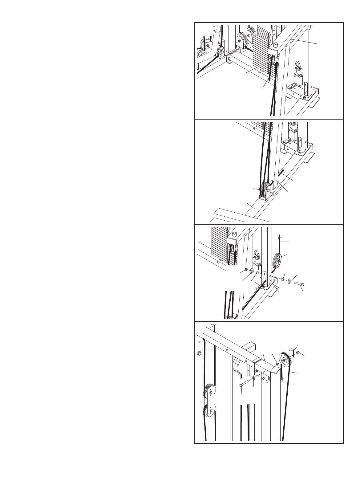
44. Wrap the Low Cable (71) over a 115mm Pulley
(47). Attach the Pulley and a Cable Trap (66) to
the second set of holes from the bottom of the
indicated pair of Pulley Plates (50) with an M10 x
50mm Bolt (111) and an M10 Nylon Locknut
(123). Make sure the Cable Trap is turned to
hold the Cable in the groove of the Pulley.
45. Wrap the Low Cable (71) under a 115mm Pulley
(47). Attach the Pulley to the indicated bracket on
the Press Base (1) with an M10 x 45mm Bolt
(110) and an M10 Nylon Locknut (123).
44
45
46
47
50
111
71
47
66
123
71
47
123
1
110
2
123
47 71
110
71
123 150
150
149
127
Bracket
Pins
49
67
67
12
118
46. Wrap the Low Cable (71) under a 115mm Pulley
(47). Attach the Pulley to the indicated bracket on
the Rear Base (2) with an M10 x 45mm Bolt (110)
and an M10 Nylon Locknut (123).
47. Note: The following steps are shown from the
back of the weight system.
Wrap the Low Cable (71) over the Special Pulley
(49). Attach the Pulley, the Switch Cable Trap (127,
this cable trap is labeled), the Two-hole Switch
Bracket (67), and the Single-hole Switch Bracket
(150) to the indicated bracket on the Rear Top
Frame (12) with an M10 x 53mm Bolt (149), an
M10 Washer (118), and an M10 Nylon Locknut
(123). Make sure that the Switch Brackets are
oriented as shown in the right inset drawing,
and that the pins on the Switch Brackets are
inserted into the holes in the indicated bracket.
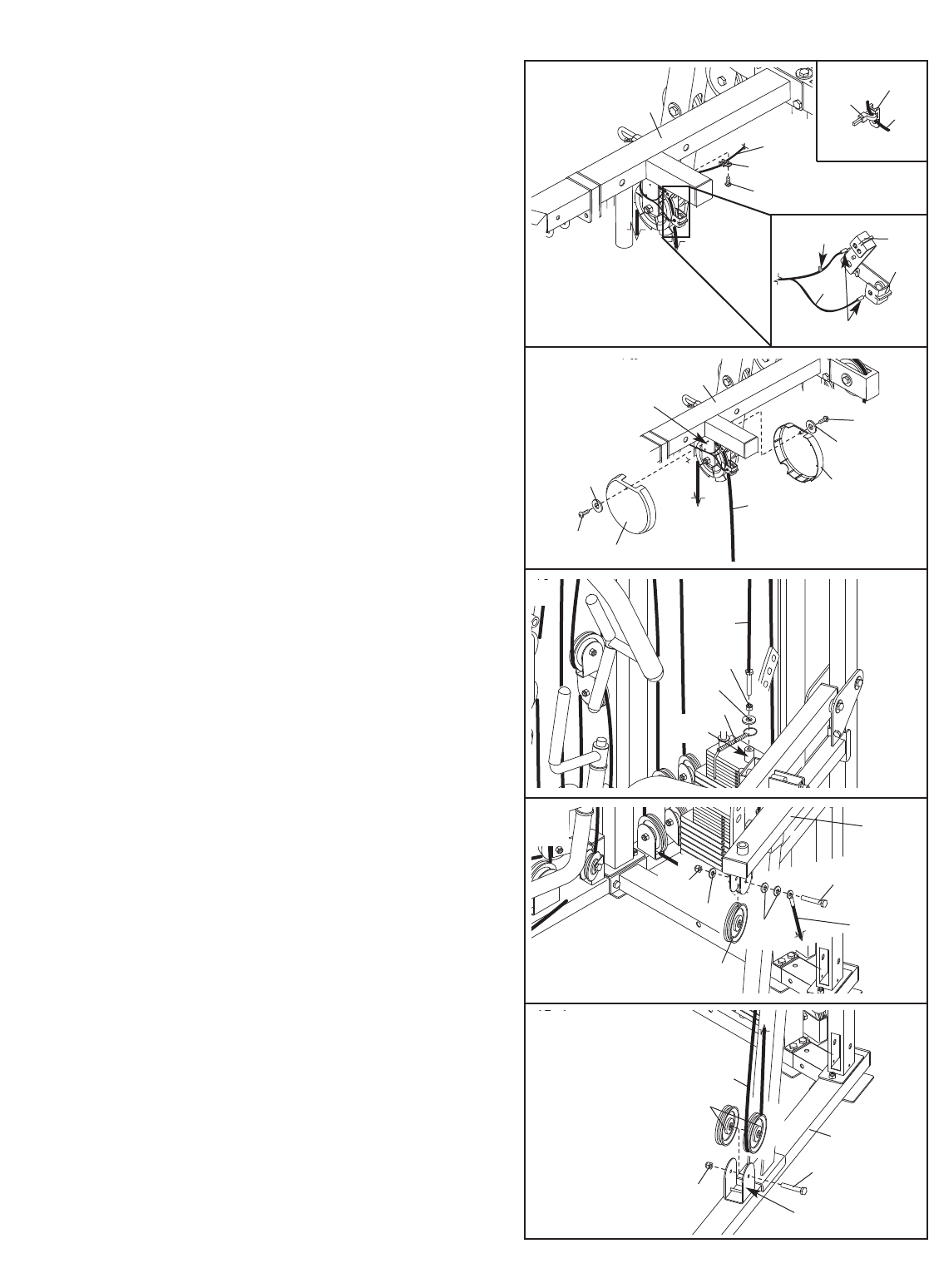
21
50. Slide the ring on the Weight Pin (93) onto tube on
the Top Weight (26). Rest the M12 Washer (138)
on the tube.
Thread an M12 Nut (137) onto the end of the Low
Cable (71). Thread the Cable into the tube in the
Top Weight (26) until there is no slack in the
Cable.
Tighten the M12 Nut (137) against the M12
Washer (138).
52. Wrap the Hack Squat Cable (72) under a 115mm
Pulley (47). Attach the Pulley, along with another
115mm Pulley, to the bracket on the Hack Squat
Base (3) with an M10 x 70mm Bolt (114) and an
M10 Nylon Locknut (123). Do not tighten the
Locknut yet. Make sure the Cable goes under
the indicated Pulley.
51. Locate the Hack Squat Cable (72). Attach the
Cable and a 115mm Pulley (47) to the Hack
Squat Bracket (5) with an M8 x 55mm Shoulder
Bolt (142), two M10 Washers (118), an M8
Washer (124), and an M8 Nylon Locknut (134).
Do not tighten the Locknut yet.
50
51
52
71
Tube
137
138
134
124
47
118 72
142
5
47
123
114
3
Bracket
72
93
49
71
68
68
48
117
48
117
Bracket
12
48
150
Sensors
Tab
80
80
80
115
67
153
153
154
B
A
12
48.See inset drawing A. Insert the indicated sensor
on the Reed Switch Wire (80), marked with the
tab, into the upper hole in the Two-hole Switch
Bracket (67) as shown. Insert the other sensor on
the Switch Wire into the Single-hole Switch
Bracket (150). Make sure that the Switch Wire
sensors are flush with the inside edge of the
Switch Brackets.
See inset drawing B. Attach the Reed Switch
Wire (80) to the Flat Tie holder (153) with the Zip
Tie (154).
Attach the Flat Tie Holder (153) to the bottom of
the Rear Top Frame (12) with an M4 x 20mm Self-
tapping Screw (115).
49. Attach the two Pulley Covers (68) to the Rear Top
Frame (12) with two M5 x 15mm Screws (117) and
two M5 Washers (48).
22
54. Route the Hack Squat Cable (72) under the other
115mm Pulley (47) attached to the Hack Squat
Base (3) in step 52, and through the Hack Squat
Leg (4).
Tighten the M10 Nylon Locknut (123) used in
step 50.
56. Wrap the Hack Squat Cable (72) over a 115mm
Pulley (47). Attach the Pulley and a Cable Trap
(66) to the Hack Squat Upright (6) with an M10 x
127mm Bolt (107), an M10 Washer (118), a
15mm x 8mm Spacer (94), and an M10 Nylon
Locknut (123). Make sure the Cable Trap is ori-
ented to hold the Cable in the groove of the
Pulley.
55. Route the Hack Squat Cable (72) under a 115mm
Pulley (47) and through the Hack Squat Upright
(6). Attach the Pulley inside the Upright with an
M10 x 67mm Bolt (109), two M10 Washers (118),
two 15mm x 12mm Spacers (86), and a M10
Nylon Locknut (123).
54
55
56
72
47
86
86
6
118
118
123
109
4
3
47
72
107
123
66
47
72
694
118
53. Route the Hack Squat Cable (72) over the
115mm Pulley (47) attached to the Hack Squat
Bracket (5) in step 49. Tighten M8 Nylon
Locknut (not shown) used in step 51.
53
72
47
5
23
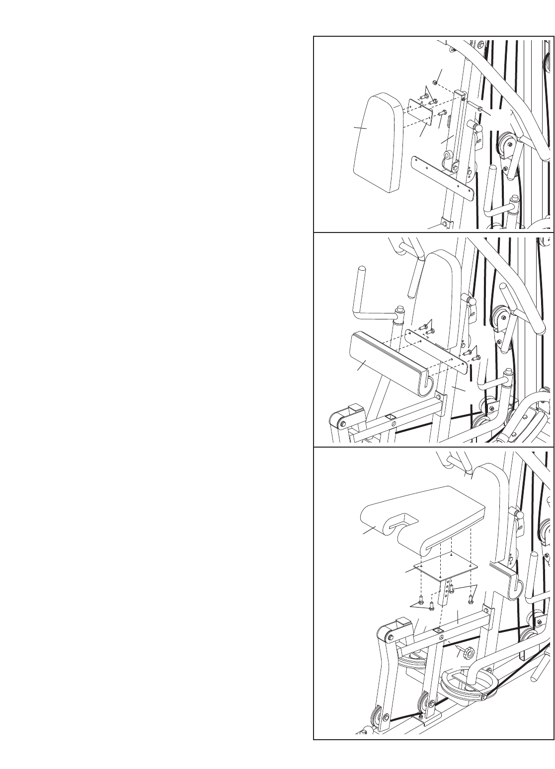
58. Locate and open the parts bag labeled “SEAT
ASSEMBLY.”
Attach the Hack Squat Backrest (32) to the Hack
Squat Frame (31) with four M6 x 20mm Screws
(112).
60. Press two 25mm x 50mm Inner Caps (101) into
the Backrest Frame (13). Attach a 25mm Bumper
(63) and a 38mm Bumper (85) to the Backrest
Frame with two M4 x 20mm Self-tapping Screws
(115) and two M4 Washers (144).
Slide the adjustment bracket on the Backrest
Frame (13) through the bracket on the Front
Upright (9). Tighten the Backrest Knob (77) into
the Upright and engage the adjustment bracket.
Attach the Backrest Frame (13) to the Front
Upright (9) with an M10 x 80mm Bolt (131) and
an M10 Nylon Locknut (123). Do not overtighten
the Locknut; the Backrest Frame must be able
to pivot easily.
59. Attach a Right Small Pad (36) to the Hack Squat
Frame (31) with two M6 x 20mm Screws (112).
Attach a Left Small Pad (37) to the Hack Squat
Frame (31) in the same manner.
58
112
112
32
31
59
112 31
36 37
60
144
144
85
9
63
115
115
Seat Assembly
101
101
123
131
77
13
Adjustment
Bracket
Bracket
57. Attach the end of the Hack Squat Cable (72) to
the Clip End (83) on the Low Cable (71). 57
72
71
83
24
62. Attach the Long Leg Pad (35) to the Front Upright
(9) with four M6 x 20mm Screws (112).
63. Attach the Seat (33) to the Seat Post (14) with
four M6 x 25mm Screws (129).
Slide the Seat Post (14) into the Seat Frame (10)
and secure it with the Seat Knob (76).
62
63
129
129
76
10
35
9
112
33
14
112
61. Attach the Backrest (34) to the Backrest Plate
(24) with three M8 x 20mm Screws (113).
Attach the Backrest Plate (24) to the Backrest
Frame (13) with M10 x 80mm Bolt (131) and an
M10 Nylon Locknut (123). Do not overtighten
the Locknut; the Backrest Plate must be able
to pivot easily.
61
34
24 13
123
113
113
131
25
65. Attach the Shroud (29) to the Rear Top
Frame (12) with two M8 x 90mm Bolts (130), two
M8 Washers (124), four 15mm x 30mm Spacers
(87), and two M8 Nylon Locknuts (134).
Attach the Shroud (29) to the Rear Base (2) by
tightening the two M8 x 90mm Bolts (not shown)
used in step 9 into the weld nuts on the Shroud.
65
87
87
87
12
124
124
130
130
134
29
2
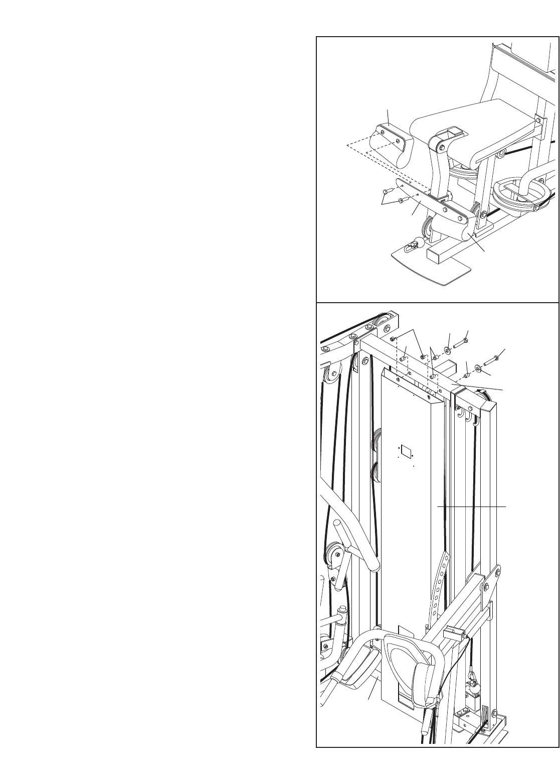
64. Attach the Right Small Pad (36) to the Pad Frame
(23) with two M6 x 20mm Bolts (112).
Attach the Left Small Pad (37) to the Pad
Frame (23) in the same manner.
64
36
112 23
37
26
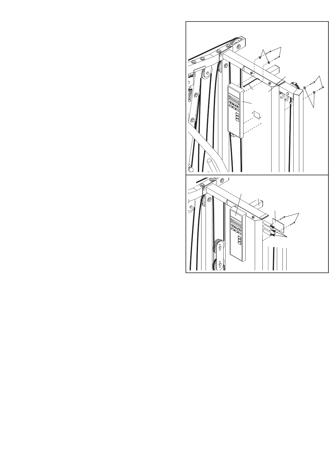
67. Insert three AA batteries into the Console (30).
Attach the Battery Cover (135) to the Console
with two M4 x 12mm Screws (141).
68. Make sure that all parts have been properly tightened. The use of the remaining parts will be explained in
ADJUSTMENTS, beginning on the following page.
Before using the weight system, pull each cable a few times to be sure that the cables move smoothly over
the pulleys. If one of the cables does not move smoothly, find and correct the problem. IMPORTANT: If the
cables are not properly installed, they may be damaged when heavy weight is used. See the CABLE
DIAGRAM on page 32 for proper cable routing. If there is any slack in the cables, you will need to
remove it by tightening the cables; see TROUBLESHOOTING AND MAINTENANCE on page 34.
67
135
Batteries
141
15
30
66. Plug the Reed Switch Wire (80) into the Console
(30).
Attach the Console (30) to the Shroud (29) with
four M4 x 20mm Self-tapping Screws (115) and
four M4 Washers (144).
66
30
80
29
115
144
144
115
This section explains how to adjust the weight system. See the EXERCISE GUIDELINES on page 35 for impor-
tant information about how to get the most benefit from your exercise program. Also, refer to the accompanying
exercise guide to see the correct form for each exercise.
Make sure all parts are properly tightened each time the weight system is used. Replace any worn parts immediate-
ly. The weight system can be cleaned with a damp cloth and a mild, non-abrasive detergent. Do not use solvents.
27
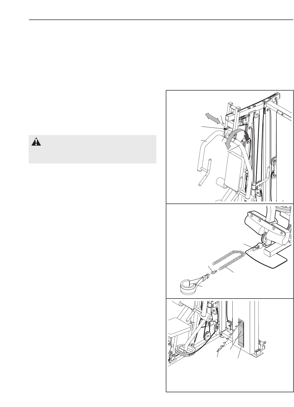
ADJUSTING THE PRESS ARM
To adjust the Press Arms (19, 20), pull the Press
Knob (78) out as far as it will go. Rotate the Press
Bracket (21) to the desired position and engage the
Press Knob into an adjustment hole.
93 28
27
CHANGING THE WEIGHT SETTING
To change the weight setting of the weight stack,
insert the Weight Pin (93) under the desired Weight
(27, 28). Make sure to insert the Weight Pin until the
bent end of the Weight Pin is touching the Weights,
and turn the bent end downward. The weight setting
of the weight stack can be changed from 5 pounds to
200 pounds, in increments of 5 and 10 pounds. Note:
Due to the cables and pulleys, the actual amount
of resistance at each exercise station may vary
from the weight setting. Use the WEIGHT
RESISTANCE CHART on page 29 to find the
approximate amount of resistance at each weight
station.
WARNING: Make sure the Press
Knob (78) is fully engaged into the Press
Bracket (21) before exercising.
ADJUSTMENTS
21
19
20
78
Adjustment
Hole
ATTACHING ACCESSORIES
Attach the Ankle Strap (103) to a Clip End (83). For
some exercises, the Chain (96) should be attached
between the Ankle Strap and the Clip End with a
Cable Clip (99). Adjust the length of the Chain
between the Ankle Strap and the Clip End so the
Ankle Strap is in the correct starting position for
the exercise to be performed.
The Lat Bar (not shown) or Ab Strap (not shown) can
be attached to any Clip End (83) in the same
manner. 103
96
99
83
31
75
5
Foot
Plate
69
36 37
3
Adjustment
Hole
28
33
76
34
13
77
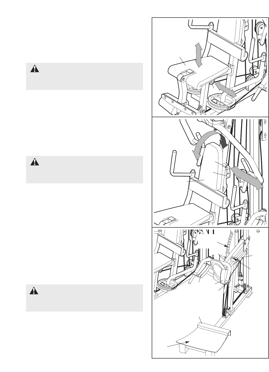
ADJUSTING THE SEAT
To adjust the height of the Seat (33), remove the Seat
Knob (76). Position the Seat at the desired height and
tighten the Knob into an adjustment hole in the Seat
Post (not shown). Fully tighten the Knob.
ADJUSTING THE HACK SQUAT
Stand on the foot plate on the Hack Squat Base (3)
with your shoulders under the Small Pads (36, 37).
Squeeze the Release Handle (69) and move the
Hack Squat Frame (31) to the desired position.
Release the Handle, and engage the Release Pin
(75) into an adjustment hole in the Hack Squat
Bracket (5).
WARNING: Make sure the Release
Pin (75) fully engages the Hack Squat Bracket
(5) before using the Hack Squat.
ADJUSTING THE BACKREST
To adjust the position of the Backrest (34), pull the
Backrest Knob (77) out as far as it will go. Set the
Backrest in the desired position and engage the Knob
into an adjustment hole in the Backrest Frame (13).
WARNING: Make sure the Backrest
Knob (77) fully engages the Backrest Frame (13)
before using the Backrest (34).
WARNING: Make sure the Seat
Knob (76) fully engages the Seat Post (14)
before using the Seat (33).

29
WEIGHT
PLATES
PRESS
ARM
(lbs.)
BUTTER-
FLY ARM
(lbs.)
LEG
LEVER
(lbs.)
HIGH
PULLEY
(lbs.)
AB
PULLEY
(lbs.)
LOW
PULLEY
(lbs.)
HACK
SQUAT
(lbs.)
Top
1
2
3
4
5
6
7
8
9
10
11
12
13
14
15
16
17
18
19
20
21
22
23
30
35
40
48
52
58
64
70
78
89
100
110
120
131
142
153
164
174
185
196
206
217
227
238
17
19
22
24
28
32
34
36
40
45
49
54
59
63
67
72
77
81
85
89
94
-
-
-
20
26
32
36
42
47
52
58
70
82
85
96
105
116
127
138
149
160
172
184
196
206
219
234
17
22
28
34
41
50
56
65
76
86
96
106
116
126
135
145
158
168
178
188
200
211
221
233
18
23
27
32
38
42
46
51
63
73
83
93
103
113
124
134
144
153
163
173
183
192
201
211
20
26
32
36
42
47
52
58
70
82
85
96
105
116
127
138
149
160
172
184
196
206
219
234
58
70
79
85
105
116
127
135
149
165
181
196
211
226
242
257
272
289
305
319
335
351
366
381
This chart shows the approximate weight resistance at each station. “Top” refers to the 5-pound top weight. The
other numbers refer to the seven 5-pound weight plates and the sixteen 10-pound weight plates. Note: The
actual resistance at each weight station may vary due to differences in individual weight plates, as well
as friction between the cables, pulleys, and weight guides. Weight resistance shown for the butterfly arm
station is for each butterfly arm. Note: Use only the top 20 weights with the butterfly arms.
WEIGHT RESISTANCE CHART
30
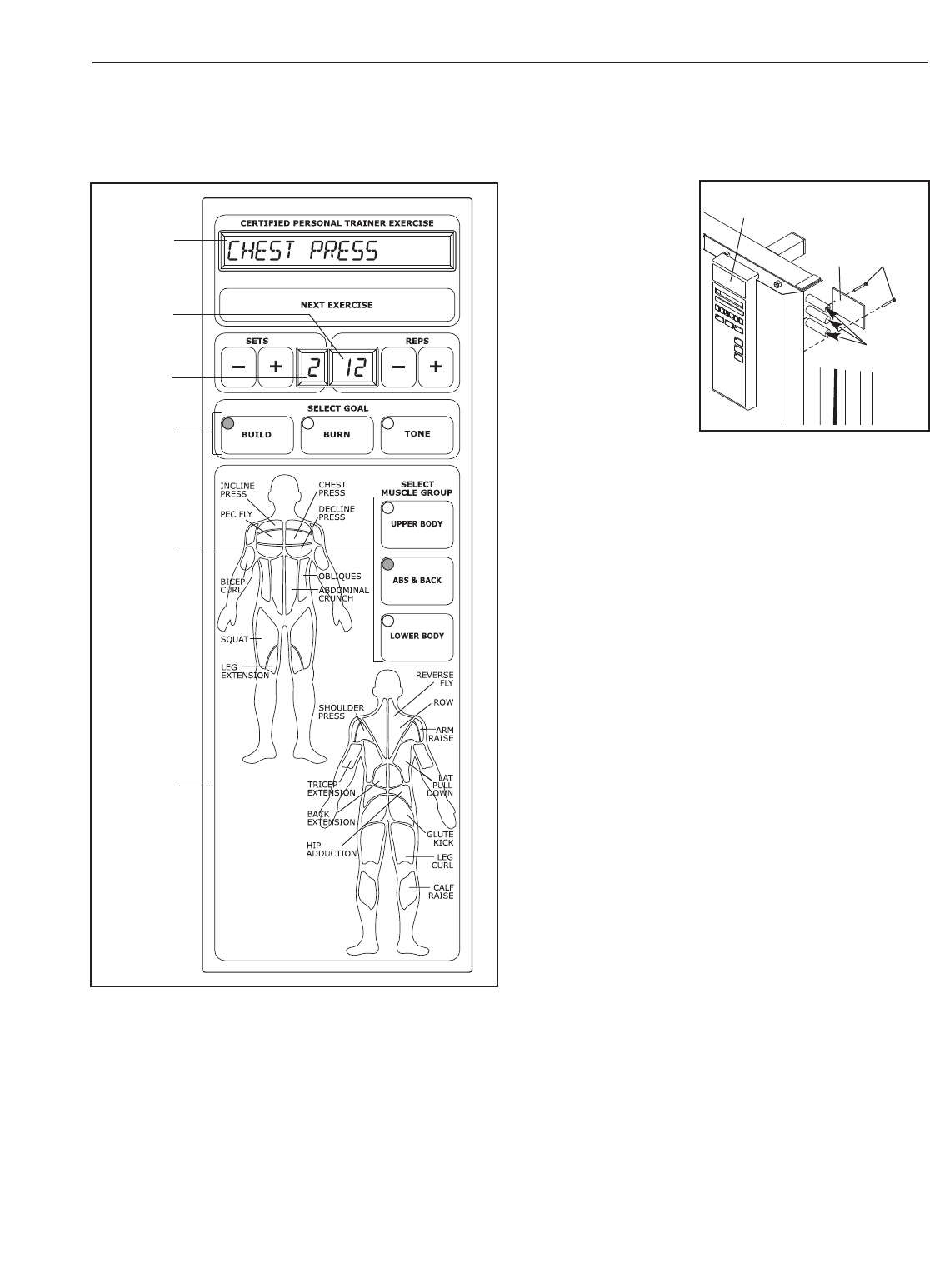
FEATURES OF THE CONSOLE
The heart of the weight system is the digital coach
console. The console offers both a manual mode and
nine workout programs. When a program is selected,
the console will guide you through an effective upper
body, ab and back, or lower body workout.
To use the manual mode of the console, follow the
steps at the right. To use a program, see page 31.
REPLACING THE BATTERIES
To replace the bat-
teries in the Console
(30), remove the
two M4 x 12mm
Screws (141) from
the Battery Cover
(135) and the
Console. Insert
three new AA batter-
ies into the Console.
Reattach the Battery
Cover with two M4 x
12mm Screws.
MANUAL OPERATION
1. Turn on the console.
Press the NEXT EXERCISE button to turn the con-
sole on. When the power is on, the words MANUAL
MODE will appear in the main display. To use a pro-
gram, see PROGRAM OPERATION on page 31.
Note: If you want to return to the manual mode while
the console is running a workout program, press
and hold the NEXT EXERCISE button.
2. Select a weight setting.
Select the desired weight setting as described in
CHANGING THE WEIGHT SETTING on page 27.
3. Enter the numbers of sets and repetitions that
you plan to complete for an exercise.
To enter the number of sets that you plan to do,
press the SETS + and – buttons. To enter the num-
ber of repetitions that you plan to do, press the
REPS + and – buttons.
Note: If you do not enter the numbers of sets and
repetitions that you plan to do, the console will
count the total number of repetitions that you com-
plete during your workout.
4. Perform the exercise.
If you have entered numbers of sets and repeti-
tions, the console will count down the repetitions
and sets you have completed. When you complete
the exercise, repeat steps 2 and 3 above for the
next exercises.
CONSOLE OPERATION
Main
Display
Goal
Buttons
Muscle
Group
Buttons
Console
Sets
Display
Reps
Display
135
Batteries
141
30

31
5. Turn off the console.
The console will turn off after it has been idle for
ten minutes.
PROGRAM OPERATION
1. Turn on the console.
Press the NEXT EXERCISE button to turn the con-
sole on. When the power is on, the words MANUAL
MODE will appear in the main display.
2. Select a program.
To select a program, press one of the three GOAL
buttons and one of the three MUSCLE GROUP
buttons. The indicators on the buttons you press
will light.
Note: The console offers three upper body pro-
grams, three ab and back programs, and three
lower body programs. If you wish to exercise your
upper body and if your goal is to lose weight, for
example, press the BURN button and the UPPER
BODY button.
3. Row for five minutes to warm up.
When a program is selected, the words CARDIO
ROW will appear in the main display. To warm up,
select the desired weight setting as described in
CHANGING THE WEIGHT SETTING on page 27.
Perform the cardio row exercise while the main dis-
play counts down from 5 minutes.
Note: To see the correct form for the cardio row
exercise, see the included exercise guide.
4. Adjust the numbers of sets and repetitions for
the exercise if desired.
The name of an exercise in the program will
appear in the main display. The recommended
numbers of sets and repetitions for the exercise will
appear in the two displays below the main display.
The recommended numbers of sets and repetitions
may be too high or too low for you, depending on
such factors as your body size and your physical
condition. If desired, adjust the numbers of sets
and repetitions by pressing the + and – buttons
next to each display.
5. Select a weight setting.
Select the desired weight setting as described in
CHANGING THE WEIGHT SETTING on page 27.
6. Perform the exercise.
As you perform the exercise, the console will count
down the numbers of sets and repetitions you have
completed.
When you complete the exercise, the word REST-
ING will appear in the main display. It is recom-
mended that you rest while the main display counts
down.
7. Perform the remaining exercises in the program.
After you have completed an exercise in the pro-
gram, press the NEXT EXERCISE button. The
name of the next exercise will appear in the main
display. Repeat steps 4–6 above for the exercise.
Note: The program may include the same exercise
twice, with different numbers of sets and repeti-
tions. If you wish to skip any part of the program,
press the NEXT EXERCISE button to advance to
the next part of the program.
When you complete the program, the words
WORKOUT COMPLETE will appear in the main
display.
8. Turn off the console.
The console will turn off after it has been idle for
ten minutes.
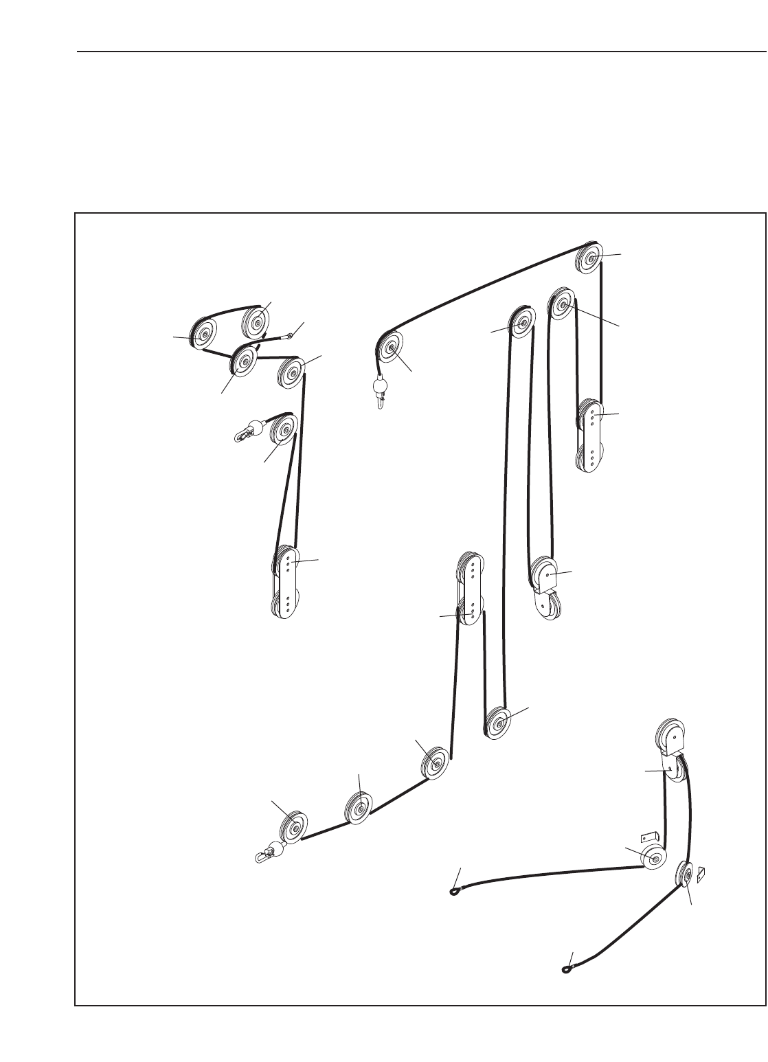
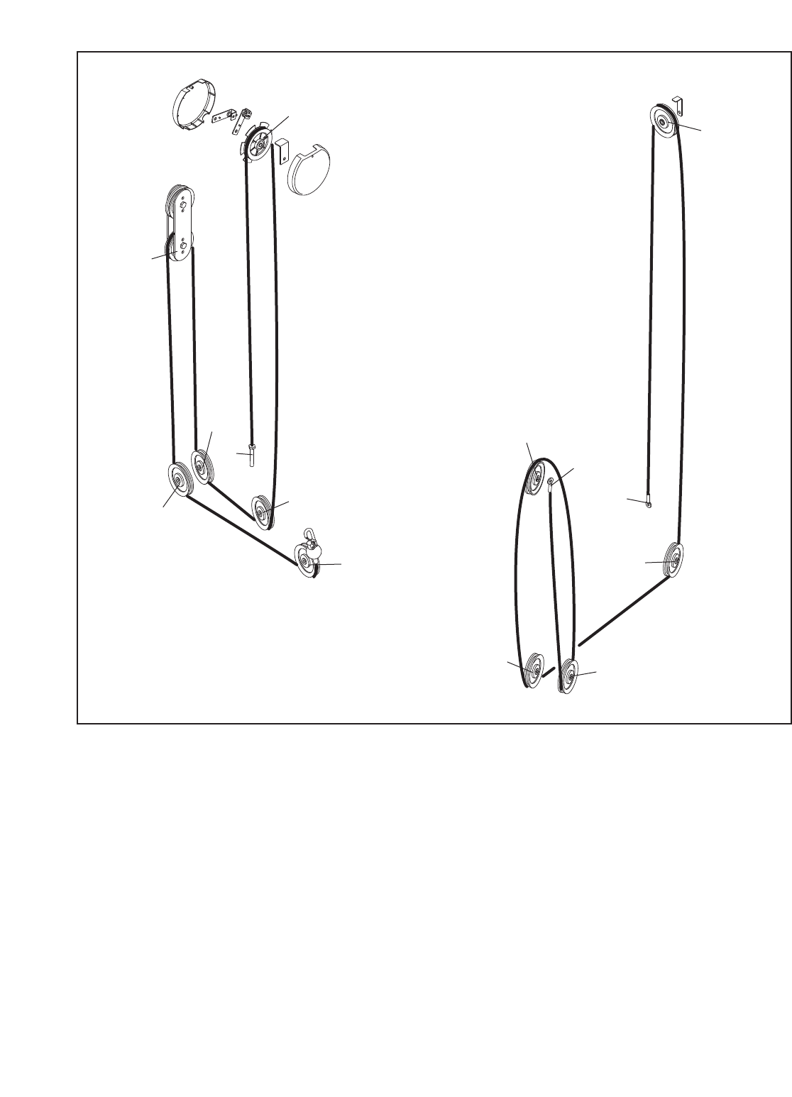
CABLE DIAGRAMS
The cable diagrams on page 30 and 31 show the proper routing of the Butterfly Cable (39), the Ab Cable (70),
the High Cable (81), the Low Cable (71), and the Hack Squat Cable (72). Use the diagram to make sure that the
cables have been assembled correctly. If the cables have not been correctly routed, the weight system will not
function properly and damage may occur. The numbers show the correct route for each cable. Make sure that
the cable traps do not touch or bind the cables.
5
3
6
4
2
1
5
64
7
8
9
10
1
2
11
Ab Cable (70)
Length: 11 feet 1 inch High Cable (81)
Length: 31 feet
Butterfly Cable (39)
Length: 9 feet 2 inches
7
2
3
1
32
3
4
5
1
2
4
4
5
2
7
6
3
1
7
3
6
5
33
Low Cable (71)
Length: 17 feet 6 inches
Hack Squat Cable (72)
Length: 21 feet 6 inches
34
TROUBLESHOOTING AND MAINTENANCE
Make sure all parts are properly tightened each time the weight system is used. Replace any worn parts immedi-
ately. The weight system can be cleaned using a damp cloth and mild non-abrasive detergent. Do not use solvents.
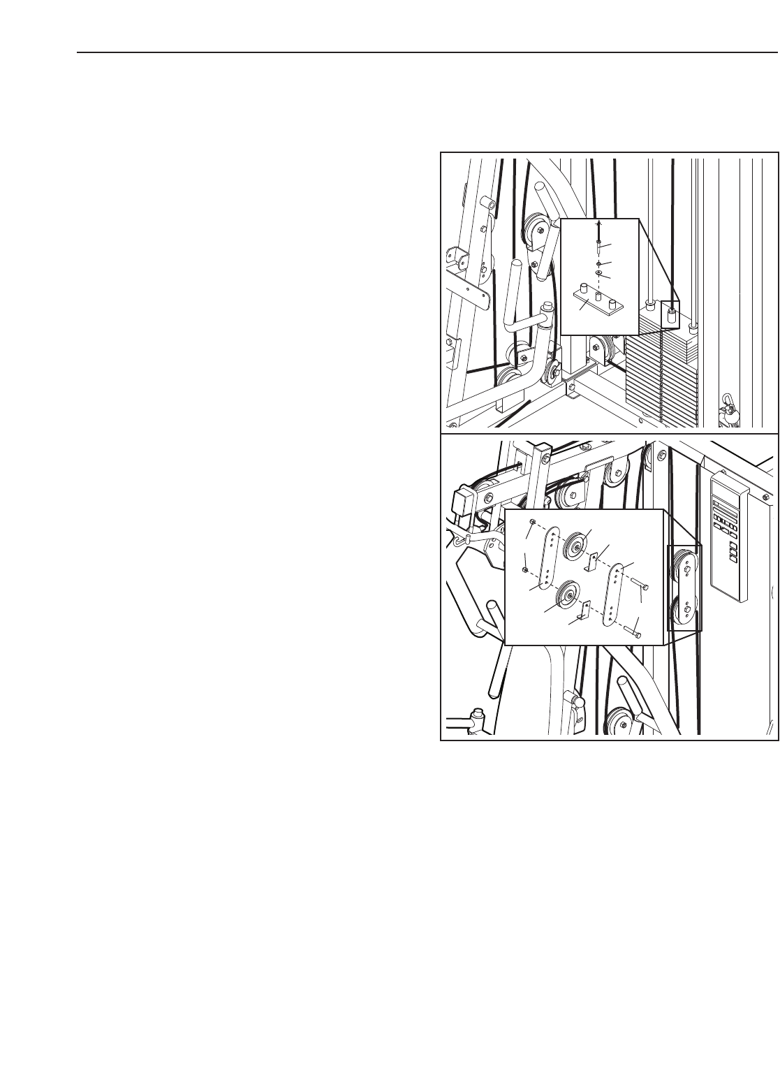
TIGHTENING THE CABLES
Woven cable, the type of cable used on the weight
system, can stretch slightly when it is first used. If
there is slack in the cables before resistance is felt,
the cables should be tightened. Make sure that the
cables are not too tight, or the Top Weight (26) will be
lifted off the weight stack.
Slack can be removed from the cables by tightening
the Low Cable (71) into the Top Weight (26). To do
this, loosen the M12 Nut (137) on the Cable. Turn the
Cable a few turns into the Top Weight, until there is no
slack in the cables. Retighten the M12 Nut against the
M12 Washer (138).
Additional slack can be removed by moving a 115mm
Pulley (47) to a set of holes that is closer to the center
of two Pulley Plates (50). Remove the M10 Nylon
Locknut (123) and the M10 x 50mm Bolt (111) from
the Cable Trap (66), Pulley, and Pulley Plates. Re-
attach the Pulley and Cable Trap to the Pulley Plates
with the Bolt and Locknut. Make sure that the Cable
Trap is positioned to hold the Cable in place, and
that the Cable and Pulley move smoothly.
Note: If a cable tends to slip off the pulleys often,
the cable may have become twisted. Remove the
cable and re-install it.
If the cables need to be replaced, see ORDERING
REPLACEMENT PARTS on the back cover of this
manual.
123
50
47
47
66
66
50
111
71
26
137
138

35
EXERCISE GUIDELINES
THE FOUR BASIC TYPES OF WORKOUTS
Muscle Building—Increase your muscle size by
using a high amount of resistance. Your muscles will
adapt and grow as you progressively increase the
intensity of your exercise by:
• changing the level of resistance
• changing the number of repetitions or sets per-
formed. (A “repetition” is one complete cycle of an
exercise, such as one sit-up. A “set” is a series of
repetitions.)
The proper amount of resistance for each exercise
depends upon the individual user. You must gauge
your limits and select the amount of resistance that is
right for you. Begin with 3 sets of 8 repetitions for each
exercise you perform. Rest for 3 minutes after each
set. When you can complete 3 sets of 12 repetitions
without difficulty, increase the amount of resistance.
Rest for 3 minutes after each set.
Toning—Tone your muscles by using a moderate
amount of resistance and increasing the number of
repetitions in each set. Complete as many sets of
15–20 repetitions as possible without discomfort. Work
your muscles by completing more sets rather than by
using high amounts of resistance. Rest for 1 minute
after each set.
Weight Loss—Lose weight by using a low amount of
resistance and increase the number of repetitions in
each set. Exercise for 20 to 30 minutes, resting for a
maximum of 30 seconds between sets.
Cross Training—Cross training is an efficient way to
get a complete and well-balanced fitness program. An
example of a balanced program is:
• Strength training workouts on Monday, Wednesday,
and Friday.
• 20–30 minutes of aerobic exercise, such as riding an
exercise bike or running on a treadmill, on Tuesday
and Thursday.
• Rest from both strength training and aerobic exercise
for at least one full day each week to give your body
time to regenerate.
The combination of strength training and aerobic exer-
cise will reshape and strengthen your body, plus devel-
op your heart and lungs.
PERSONALIZING YOUR EXERCISE PROGRAM
Determining the exact length of time for each workout,
as well as the number of repetitions or sets completed,
is an individual matter. It is important to avoid overdo-
ing it during the first few months of your exercise pro-
gram. You should progress at your own pace and be
sensitive to your body’s signals. If you experience pain
or dizziness at any time while exercising, stop immedi-
ately and begin cooling down. Find out what is wrong
before continuing. Remember that adequate rest and a
proper diet are important factors in any exercise pro-
gram.
Warming Up—Begin each workout with 5 to 10 min-
utes of stretching and light exercise to warm up.
Warming up prepares your body for more strenuous
exercise by increasing circulation, raising your body
temperature and delivering more oxygen to your mus-
cles.
Working Out—Each workout should include 6 to 10
different exercises. Select exercises for every major
muscle group, emphasizing areas that you want to
develop most. To give balance and variety to your
workouts, vary the exercises from session to session.
Schedule your workouts for the time of day when your
energy level is the highest. Each workout should be
followed by at least one day of rest. Once you find the
schedule that is right for you, stick with it.
Exercise Form—Maintaining proper form is an essen-
tial part of an effective exercise program. This requires
moving through the full range of motion for each exer-
cise, and moving only the appropriate parts of the
body. Exercising in an uncontrolled manner will leave
you feeling exhausted.
The repetitions in each set should be performed
smoothly and without pausing. The exertion stage of
each repetition should last about half as long as the
return stage. Proper breathing is important. Exhale
during the exertion stage of each repetition and inhale
during the return stroke. Never hold your breath. Rest
for a short period of time after each set. The time
depends on which type of workout you are performing
(see THE FOUR BASIC TYPES OF WORKOUTS).
Plan to spend the first couple of weeks familiarizing
yourself with the equipment and learning the proper
form for each exercise.
Cooling Down—End each workout with 5 to 10 min-
utes of stretching. Include stretches for both your arms
and legs. Move slowly as you stretch and do not
bounce. Ease into each stretch gradually and go only as
far as you can without strain. Stretching at the end of
each workout is an effective way to increase flexibility.
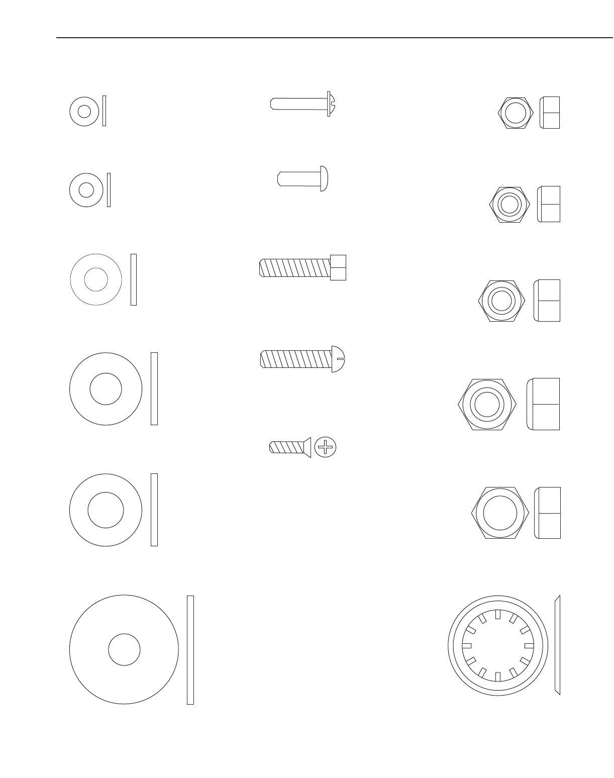
M5 Washer (127)
M8 Washer (124)
M8 Nylon Locknut (134)
M12 Nylon Locknut (151)
M12 Nut (137)
M4 Washer (144)
M10 Nylon Locknut (123)
M10 Large Washer (122)
M10 Washer (118)
M12 Washer (138)
25mm Retainer (119)
M7 Nut (120)
M4 x 20mm Self-tapping Screw (115)
M5 x 15mm Screw (117)
M6 x 25mm Screw (129)
M6 x 25mm Button Screw (116)
M4 x 12mm Screw (141)
PART IDENTIFICATION CHART—Model No. FMSY99530 R0504A
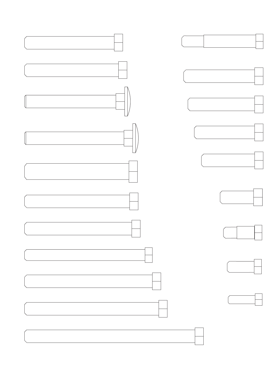
M10 x 74mm Carriage Bolt (102)
M10 x 68mm Carriage Bolt (104)
M10 x 95mm Bolt (105)
M10 x 25mm Bolt (106)
M10 x 127mm Bolt (107)
M10 x 78mm Bolt (108)
M10 x 67mm Bolt (109)
M10 x 45mm Bolt (110)
M10 x 50mm Bolt (111)
M10 x 70mm Bolt (114)
M10 x 100mm Bolt (128)
M10 x 80mm Bolt (131)
M10 x 40mm Bolt (148)
M10 x 53mm Bolt (149)
M6 x 20mm Bolt (112)
M8 x 20mm Bolt (113)
M8 x 90mm Bolt (130)
M8 x 55mm Shoulder Bolt (142)
M8 x 23mm Shoulder Bolt (152)
M12 x 78mm Bolt (146)
50mm x 75mm Inner Cap (53)
56mm Round Inner Cap (56)
40mm x 50mm Inner Cap (60)
50mm Square Inner Cap (61)
26mm x 76mm Inner Cap (62)
25mm Round Cover Cap (65)
25mm x 50mm Inner Cap (101)
15mm x 12mm Spacer (86)
15mm x 30mm Spacer (39)
15mm x 8mm Spacer (94)

Note: “#” indicates a non-illustrated part. Specifications are subject to change without notice. See the back cover
of the user’s manual for information about ordering replacement parts.
Key
No. Qty. Description
Key
No. Qty. Description
Key
No. Qty. Description
1 1 Press Base
2 1 Rear Base
3 1 Hack Squat Base
4 1 Hack Squat Leg
5 1 Hack Squat Bracket
6 1 Hack Squat Upright
7 1 Left Rear Upright
81 Right Rear Upright
9 1 Front Upright
10 1 Seat Frame
11 1 Press Top Frame
12 1 Rear Top Frame
13 1 Backrest Frame
14 1 Seat Post
15 1 Leg Lever
16 1 Left Butterfly Arm
17 1 Right Butterfly Arm
18 2 Butterfly Handle
19 1 Left Press Arm
20 1Right Press Arm
21 1 Press Bracket
22 1 Press Frame
23 1Pad Frame
24 1 Backrest Plate
25 2 Weight Guide
26 1 Top Weight
27 7 Small Weight
28 16 Large Weight
29 1Shroud
30 1Console
31 1 Hack Squat Frame
32 1 Hack Squat Backrest
33 1Seat
34 1 Backrest
35 1 Long Leg Pad
36 2 Right Small Pad
37 2 Left Small Pad
38 4 Small Support Bushing
39 1 Butterfly Cable
40 1 Short Handgrip
41 1 Long Handgrip
42 2 Short Press Handgrip
43 2 Butterfly Handgrip
44 2 Barbell Hook Sleeve
45 2 Long Pivot Rod
46 2 Short Pivot Rod
47 30 115mm Pulley
48 2 M5 Washer
49 1 Special Pulley
50 4Pulley Plate
51 1Left Foot
52 1Right Foot
53 9 50mm x 75mm Inner
Cap
54 1 81mm x 58mm Metal
Cap
55 1 81mm x 58mm Angled
Outer Cap
56 2 56mm Round Inner Cap
57 4 Butterfly Handle
Bushing
58 6 25mm Round Inner Cap
59 1 56mm Angled Square
Outer Cap
60 5 40mm x 50mm Inner
Cap
61 4 50mm Square Inner Cap
62 1 26mm x 76mm Inner
Cap
63 1 25mm Bumper
64 1 50mm Angled Square
Inner Cap
65 3 25mm Round Outer Cap
66 7 Cable Trap
67 1 Two-hole Switch Bracket
68 2 Pulley Cover
69 1 Release Handle
70 1 Ab Cable
71 1Low Cable
72 1 Hack Squat Cable
73 1 Release Cable
74 1Cable Cover
75 1 Release Pin
76 1 Seat Knob
77 1 Backrest Knob
78 1 Press Knob
79 1 Pad Frame Knob
80 1 Reed Switch Wire
81 1High Cable
82 4 Cable Ball
83 4 Clip End
84 2Rod Cover
85 2 38mm Bumper
86 20 15mm x 12mm Spacer
87 8 15mm x 30mm Spacer
88 4 Inner Bushing
89 2 Weight Bumper
90 2 Weight Guide Bushing
91 4 Press Arm Bushing
92 16 Support Rod Bushing
93 1 Weight Pin
94 1 15mm x 8mm Spacer
95 2 60mm x 80mm Bushing
96 1 Chain
97 1 Lat Bar
98 2 Lat Bar Handgrip
99 1 Cable Clip
100 1 Ab Strap
101 425mm x 50mm Inner
Cap
102 2M10 x 74mm Carriage
Bolt
103 1 Ankle Strap
104 8 M10 x 68mm Carriage
Bolt
105 8 M10 x 95mm Bolt
106 14 M10 x 25mm Bolt
107 1 M10 x 127mm Bolt
108 4 M10 x 78mm Bolt
109 9 M10 x 67mm Bolt
110 11 M10 x 45mm Bolt
111 6 M10 x 50mm Bolt
112 16 M6 x 20mm Bolt
113 3 M8 x 20mm Bolt
114 4 M10 x 70mm Bolt
115 12 M4 x 20mm Self-tapping
Screw
116 1 M6 x 25mm Button
Screw
117 2 M5 x 15mm Screw
118 38 M10 Washer
119 4 25mm Retainer
120 2 M7 Nut
121 1 Cable Adjustment Nut
122 10 M10 Large Washer
123 60 M10 Nylon Locknut
124 5 M8 Washer
125 151mm x 49mm Plate
126 1 Spring
127 1 Switch Cable Trap
128 2M10 x 100mm Bolt
129 5 M6 x 25mm Screw
130 4 M8 x 90mm Bolt
131 2 M10 x 80mm Bolt
132 14 5lb. Weight Bushing
133 32 1lb. Weight Bushing
134 8 M8 Nylon Locknut
135 1Battery Cover
136 2 Long Press Handgrip
137 1 M12 Nut
138 1M12 Washer
139 2 45mm Bushing
140 2 21mm Bushing
141 2 M4 x 12mm Screw
142 1 M8 x 55mm Shoulder
Bolt
143 2 Small Round Inner Cap
144 11 M4 Washer
145 2 63mm Bushing
146 1 M12 x 78mm Bolt
147 1 Double “U”-bracket
148 2 M10 x 40mm Bolt
149 1 M10 x 53mm Bolt
150 1 Single-hole Switch
Bracket
151 1 M12 Nylon Locknut
152 1 M8 x 23mm Shoulder
Bolt
153 1Flat Wire Holder
154 1Zip Tie
# 1 User’s Manual
# 1 Exercise Guide
# 1 Exercise Decal
# 4 Grease Pack
# 1 Allen Wrench
PART LIST—Model No. FMSY99530 R0504A
51
3
47
53
47
6
72
47
5
53
85
55
54
4
32
143
40
69
73
74
46
53
92
53 4766
104
106
107
94
115
116 118
118
122
115
144
123
123
123
134
106
104
123
123
115
52
123
123
75 129
126
36
139
41
112
112
112 112
112
139
142
72
122
38
92
46
92
122
92
122
105
86
109
118
86
118
123
123
114
60
53
120
120 121
38
143
37
31 118
118
124
144
144
101
101
123
EXPLODED DRAWING—Model No. FMSY99530 R0504A
85
24
44
1
53
91
76
10
91
86
86
86
86
81
82
83
37
36 79
95
23
95
47
47
15
58
136
91
64
59
14
16
57
18 57
65
35
86
47
47
77
9
86
47
47
47
86
86
86
84
84
11
8
53
86
47
86
53
83
82
81
70
82
83
34
58
43
58
43
65
57
18
17
33
19
20
136
58
21
92
92
92
92
60
60
92
78
92
45
45
60
60
92
92
47
92
22
87
87
62
61
70
68
127
49
67
68 80
29
25
7
89
90
89
90
71
26
87
87
47
61
83
82
71
28
93
50
47
47
66
66
50
88
2
88
96
97
98
98
99 100
103
42
42
58
13
104
104
102
105
105
105
114
114
111
106
108
108
146
109
109 106
106
109
109
109
130
130
152
109
110
106
106
130
130
110
110
110
131
113
112
112
128
128
129
129
57
114
111
111
115
117
149
112
124
124
118 118
118
118
118
118
118
118
118
118
122
122
122
122
118 118
118
118
118
118
122
118
122
118
118
124
119
119
144
123
123
134
123
123
123
123
123
123
123
134
134
151
123
134
123
123
123
106
106
123
123
123
123
123
123
123
123
123
123
134
134
123
123
134
12
27
106
56
56
101
101
92
115
115
132
132
133
133
138
137
135
144
115
144
63
124
88
140
145 145
140
131
88
65
118
123 47
91
123
66
66
110
110
47
47
47
110
123 47
110
123 47
53
110
110
123
123
147
47
86
118
86
109
118
123
148 118
86
123
148
118
86
61
39
39
150
61
86
47
86
109
118
118
123
123
86
123
123
47
110
144
125
30
50
66
66
47
47
50
111
111
123
117
48
48
87
87
87
123
87
154
141
118
153
115
EXPLODED DRAWING—Model No. FMSY99530 R0504A

Part No. 202192 R0504A Printed in China © 2003 ICON IP, Inc.
LIMITED WARRANTY
ICON Health & Fitness, Inc. (ICON), warrants this product to be free from defects in workmanship and mate-
rial, under normal use and service conditions, for a period of ninety (90) days from the date of purchase. This
warranty extends only to the original purchaser. ICON's obligation under this warranty is limited to replacing
or repairing, at ICON's option, the product at one of its authorized service centers. All products for which war-
ranty claim is made must be received by ICON at one of its authorized service centers with all freight and other
transportation charges prepaid, accompanied by sufficient proof of purchase. All returns must be pre-author-
ized by ICON. This warranty does not extend to any product or damage to a product caused by or attributa-
ble to freight damage, abuse, misuse, improper or abnormal usage or repairs not provided by an ICON author-
ized service center, products used for commercial or rental purposes, or products used as store display mod-
els. No other warranty beyond that specifically set forth above is authorized by ICON.
ICON is not responsible or liable for indirect, special or consequential damages arising out of or in connection
with the use or performance of the product or damages with respect to any economic loss, loss of property,
loss of revenues or profits, loss of enjoyment or use, costs of removal, installation or other consequential dam-
ages of whatsoever nature. Some states do not allow the exclusion or limitation of incidental or consequen-
tial damages. Accordingly, the above limitation may not apply to you.
The warranty extended hereunder is in lieu of any and all other warranties and any implied warranties of mer-
chantability or fitness for a particular purpose is limited in its scope and duration to the terms set forth herein.
Some states do not allow limitations on how long an implied warranty lasts. Accordingly, the above limitation
may not apply to you.
This warranty gives you specific legal rights. You may also have other rights which vary from state to state.
ICON HEALTH & FITNESS, INC., 1500 S. 1000 W., LOGAN, UT 84321-9813
To order replacement parts, simply call our Customer Service Department toll-free at 1-800-995-2699, Monday
through Friday, 6 a.m. until 6 p.m. Mountain Time (excluding holidays). To help us assist you, please be pre-
pared to give the following information:
1. The MODEL NUMBER of the product (FMSY99530)
2. The NAME of the product (FREEMOTION®S75 STRENGTH TRAINER weight system)
3. The SERIAL NUMBER of the product (see the front cover of this manual)
4. The KEY NUMBER and DESCRIPTION of the part(s) (see the PART LIST and EXPLODED DRAWING at the
center of this manual).
ORDERING REPLACEMENT PARTS
