Freemotion Gzfm60000 Owners Manual GZFM60003 GZ7217
Freemotion-Gzfm60003-Owners-Manual freemotion-gzfm60003-owners-manual
2014-07-19
: Freemotion Freemotion-Gzfm60000-Owners-Manual freemotion-gzfm60000-owners-manual freemotion pdf
Open the PDF directly: View PDF ![]() .
.
Page Count: 16
Visit our website at
www.proform.com
new products, prizes,
fitness tips, and much more!
Visit our website at
www.healthrider.com
new products, prizes,
fitness tips, and much more!
Visit our website at
www.nordictrack.com
new products, prizes,
fitness tips, and much more!
Visit our website at
www.weiderfitness.com
new products, prizes,
fitness tips, and much more!
Visit our website at
www.freemotionfitness.com
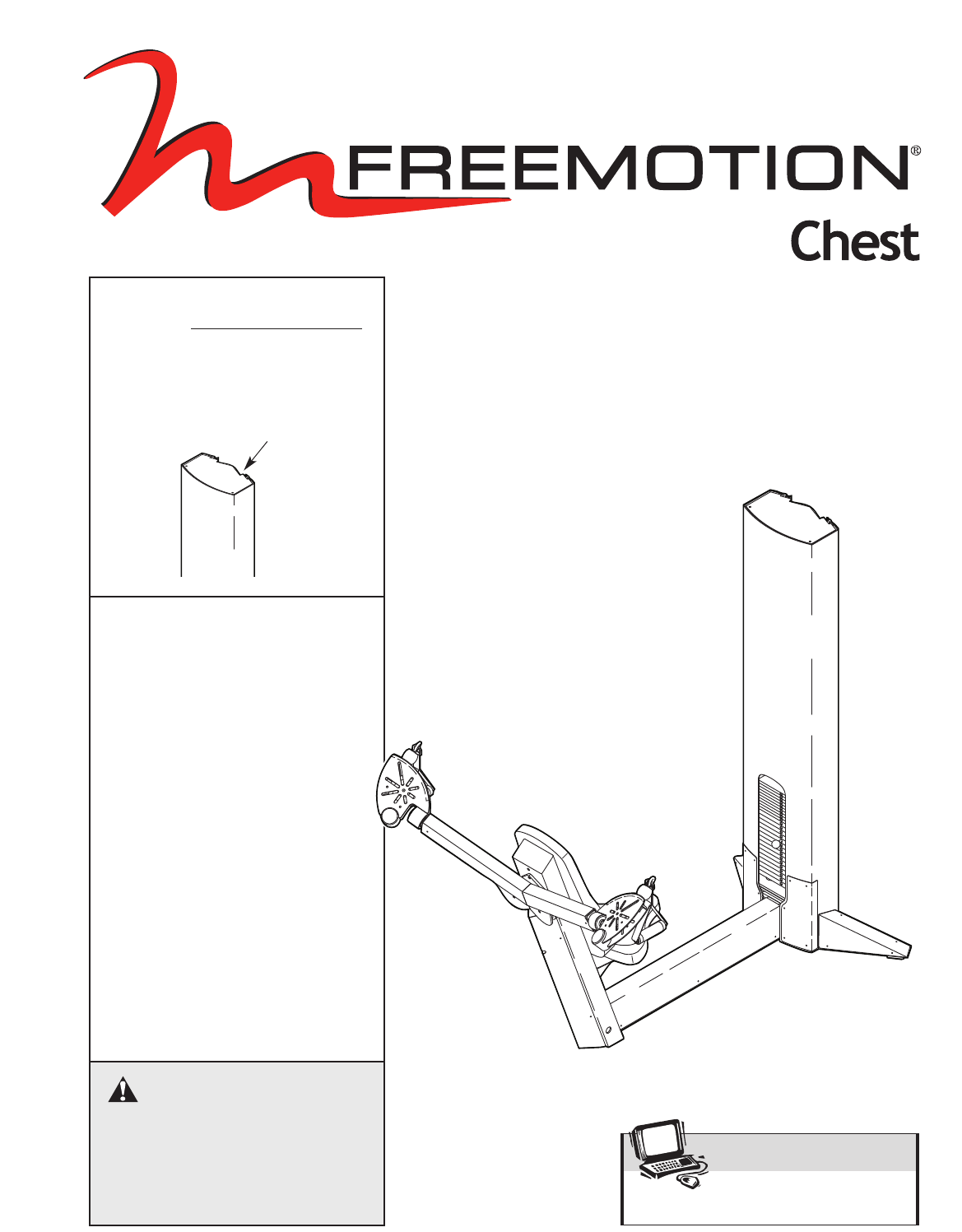
CAUTION
Read all precautions and instruc-
tions in this manual before using
this equipment. Save this manual
for future reference.
OWNER’S MANUAL
Model No. GZFM6000.3
Serial No.
Write the serial number in the
space above for future reference.
Serial Number Decal
(inside tower)
QUESTIONS?
At FreeMotion Fitness, we’re
committed to providing com-
plete customer satisfaction. If
you have questions, see HOW
TO CONTACT CUSTOMER
CARE on the back cover of this
manual.

2
IMPORTANT PRECAUTIONS . . . . . . . . . . . . . . . . . . . . . . . . . . . . . . . . . . . . . . . . . . . . . . . . . . . . . . . . . . . . . . . . 3
WARNING DECAL PLACEMENT . . . . . . . . . . . . . . . . . . . . . . . . . . . . . . . . . . . . . . . . . . . . . . . . . . . . . . . . . . . . . .4
BEFORE YOU BEGIN . . . . . . . . . . . . . . . . . . . . . . . . . . . . . . . . . . . . . . . . . . . . . . . . . . . . . . . . . . . . . . . . . . . . . . 5
ADJUSTMENTS . . . . . . . . . . . . . . . . . . . . . . . . . . . . . . . . . . . . . . . . . . . . . . . . . . . . . . . . . . . . . . . . . . . . . . . . . . . 6
MAINTENANCE . . . . . . . . . . . . . . . . . . . . . . . . . . . . . . . . . . . . . . . . . . . . . . . . . . . . . . . . . . . . . . . . . . . . . . . . . . .7
CABLE DIAGRAM . . . . . . . . . . . . . . . . . . . . . . . . . . . . . . . . . . . . . . . . . . . . . . . . . . . . . . . . . . . . . . . . . . . . . . . . .11
PART LIST . . . . . . . . . . . . . . . . . . . . . . . . . . . . . . . . . . . . . . . . . . . . . . . . . . . . . . . . . . . . . . . . . . . . . . . . . . . . . .12
EXPLODED DRAWING . . . . . . . . . . . . . . . . . . . . . . . . . . . . . . . . . . . . . . . . . . . . . . . . . . . . . . . . . . . . . . . . . . . .13
HOW TO CONTACT CUSTOMER CARE . . . . . . . . . . . . . . . . . . . . . . . . . . . . . . . . . . . . . . . . . . . . . . .Back Cover
TABLE OF CONTENTS

3
1. Read all instructions in this manual before
using the strength machine. Use the strength
machine only as described in this manual.
2. It is the purchaser’s responsibility to ensure
that there is enough space around the
strength machine for the intended exercise.
Do not crowd the strength machine.
3. Using the two 9/16” anchor holes to provide
maximum stability, the strength machine
must be anchored to the floor where required
or whenever possible.
4. Use the strength machine only on a level sur-
face. Cover the floor beneath the strength
machine to protect the floor.
5. It is the responsibility of the owner to ensure
that all users of the strength machine are
adequately informed of all precautions, have
read and understood all warning and caution
labels, and are informed of how to use the
strength machine properly.
6. Keep children under 12 and pets away from
the strength machine at all times.
7. Keep hands and feet away from moving
parts. Do not lean on or rest your hands on
the strength machine when it is in use.
8. Always wear athletic shoes for foot protec-
tion whilst exercising.
9. All users of the strength machine should be
instructed to report any injury or strength
machine irregularity to facility staff immedi-
ately.
10. Make sure the weight pin is completely
inserted into one of the weight plates.
11. Make sure the handles are attached securely
before each use of the strength machine.
12. Check all cables, cable connections, and pul-
leys before each use of the strength machine.
Make sure all parts are properly tightened.
Replace any worn parts immediately.
13. Make sure the cable remains on the pulleys
at all times. If the cable binds whilst you are
exercising, stop immediately and make sure
the cable is on the pulleys and nothing is
interfering with the cable or pulleys.
14. The strength machine is designed to support
amaximum user weight of 160 kg (350 lbs.).
15. If you feel pain or dizziness at any time
whilst exercising, stop immediately and
begin cooling down.
WARNING: Before beginning this or any exercise program, consult your physician. This
is especially important for persons over the age of 35 or persons with pre-existing health problems.
Read all instructions before using. ICON assumes no responsibility for personal injury or property
damage sustained by or through the use of this product.
WARNING: To reduce the risk of serious injury, read the following important precautions
before using the strength machine.
IMPORTANT PRECAUTIONS
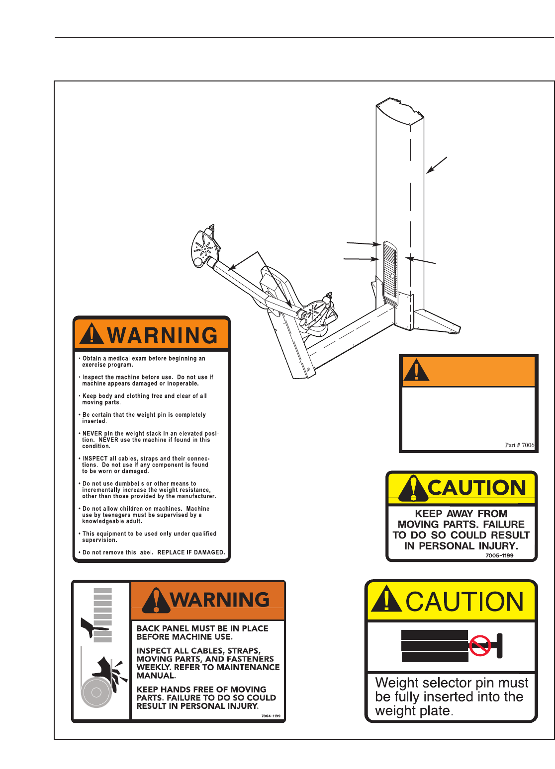
WARNING DECAL PLACEMENT
4
GZ7003
DO NOT USE
MACHINE FROM
THIS SIDE
WARNING
GZ7005
The decals shown below have been placed
on the strength machine in the indicated
locations. If a decal is missing or illegible,
see HOW TO CONTACT CUSTOMER CARE on
the back cover of this manual. Apply the decal
in the location shown.
Decal 1
Shown at 70%
PN GZ7003
Decal 4
Shown at 85%
Decal 3
Shown at 80%
Decal 2
Shown
at 50%
Decal 2
(Inside the
access cover)
Decal 5
PN GZ7026
Decal 5
Decal 4
Decal 1
Decal 3
Assembled Dimensions:
Height: 73 in./185 cm
Width: 52 in./132 cm
Depth: 71 in./180 cm
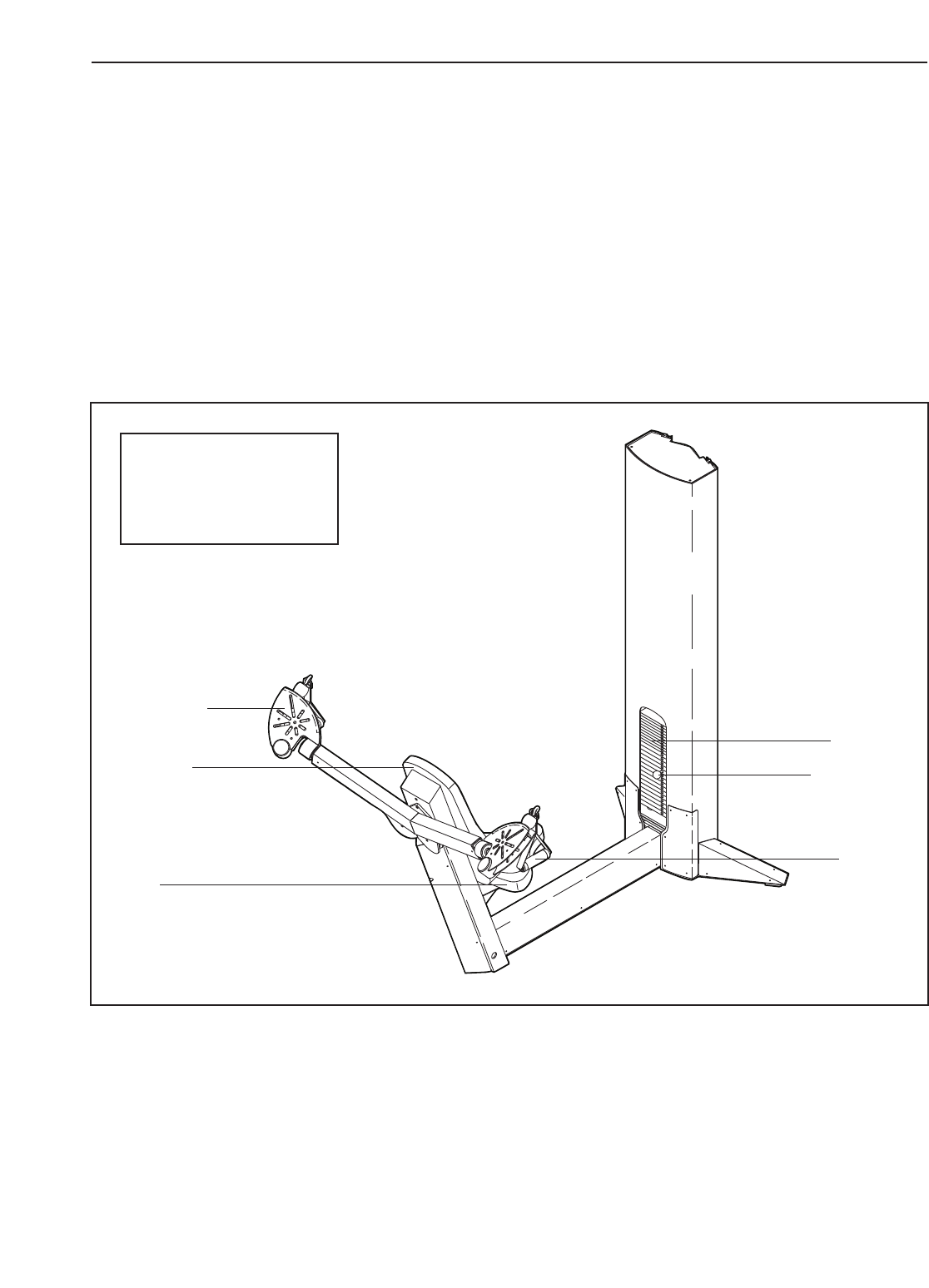
5
Backrest
Weights
Seat
Handle
Weight Pin
Swivel Arm
BEFORE YOU BEGIN
Thank you for selecting the FREEMOTION®CHEST
strength machine. With unrestricted motion, you can
work your body’s muscle groups together—the same
way you do in real life—and train more specifically and
efficiently. Whether your goal is to tone your body,
build dramatic muscle size and strength, improve your
cardiovascular system, or train muscles for precise
patterns of movement, the CHEST strength machine
will help you to achieve the specific results you want.
For your benefit, read this manual carefully before
using the strength machine. If you have questions
after reading this manual, see HOW TO CONTACT
CUSTOMER CARE on the back cover of this manual. To
help us assist you, please note the product model
number and serial number before calling. The model
number is GZFM6000.3. The serial number can be
found on a decal attached to the strength machine
(see the front cover of this manual).
Before reading further, please review the drawing
below and familiarise yourself with the parts that are
labelled.
This section explains how to adjust the strength machine. Make sure all parts are properly tightened each time
the strength machine is used. Replace any worn parts immediately.
6
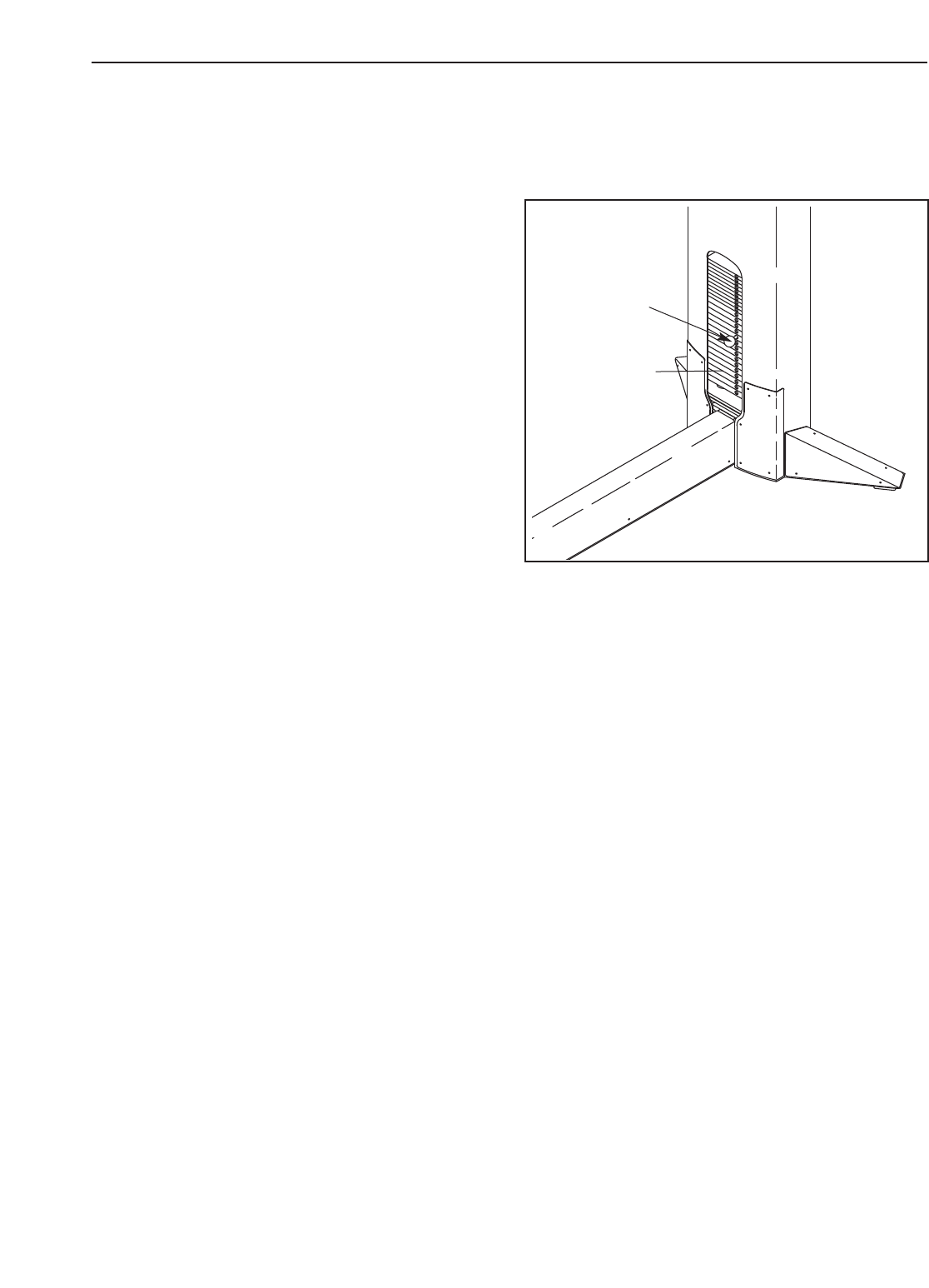
ADJUSTING THE RESISTANCE
To change the amount of resistance for your workout,
insert the weight pin into the desired weight. Make
sure that the weight pin is fully inserted into the
weight stack.
ADJUSTMENTS
Weight
Stack
Weight
Pin

7
MAINTENANCE
For safe and trouble-free operation of your FreeMotion Fitness strength equipment, it is important to perform
routine preventative maintenance on a regular basis. Make sure that all parts are properly tightened each time
the strength machine is used. Replace any worn parts immediately. The strength machine can be cleaned with a
damp cloth and a mild, non-abrasive detergent. Do not use solvents.
Note: Instruct all personnel to perform equipment inspection and maintenance requirements. Personnel must
record and report any accident. For any questions or concerns, see HOW TO CONTACT CUSTOMER CARE
on the back cover of this manual.
Use only original FreeMotion Fitness parts for repair or replacement to maintain your machine’s warranty.
FreeMotion Fitness recommends the following procedures:
SCHEDULED MAINTENANCE
DAILY
1. Upholstery—General cleaning:
•Wipe using a soft cloth dampened with a light
solution of household dish detergent and warm
water.
•If necessary, use a soft bristle brush with the
cleaning solution.
•Always remove the cleaning solution using a
cloth dampened with clean water. Rinse often.
2. Upholstery—Difficult stains:
•Spray the stain with a non-abrasive household
cleaner such as FORMULA 409®cleaner,
SIMPLE GREEN®,or a similar product.
•Rub the area gently and let it sit for a few min-
utes.
•Rinse thoroughly using a clean, water-damp-
ened cloth.
•Repeat if necessary using a soft bristle brush.
Optional method for difficult stains:
•Rub the area gently using a soft cloth damp-
ened with rubbing alcohol.
•Rinse thoroughly using a water-dampened cloth
to remove alcohol residue.
CAUTION: When using any cleaning product, try
it first in an inconspicuous place to ensure there
is no damage to the material. Follow directions
and adhere to the safety precautions of the manu-
facturer of each cleaning agent used. FreeMotion
Fitness and its vendors cannot be held liable for
damage or injuries resulting from the use or mis-
use of cleaning products.
3. Towers and Frames:
•Wipe with a light solution of mild soap and warm
water. Rinse and dry thoroughly.
Important: Do not use abrasive cleaners
because they may scratch the equipment. Strong
cleansers and abrasives will damage decals. Use
caution around decals. Do not use solvents such
as lacquer thinner, kerosene, gasoline, or similar
liquids.
4. Stainless Steel Covers:
•Wipe with a light solution of mild soap and warm
water.Rinse and dry thoroughly.
•If desired, or to remove corrosion, use available
commercial stainless steel polishing com-
pounds. Follow manufacturers’ instructions.
5. Handles:
•Check all straps for wear.
•Visually check each strap along the full length
for signs of wear such as cuts, tears, or nicks.
Replace the strap immediately if necessary.
•A“fuzz” will appear on straps over time and is
not a concern unless it appears to be worn
through strands of the weave.
6. Straps with Rings:
•If a ring is pulling through the strap or tearing
away from the edge of the strap, replace the
strap immediately.
•Check stitching points on straps for tears, worn
spots, or separation. Replace the strap if neces-
sary.
WEEKLY
1. Hardware:
•Check all nuts and bolts. Tighten them as
required.
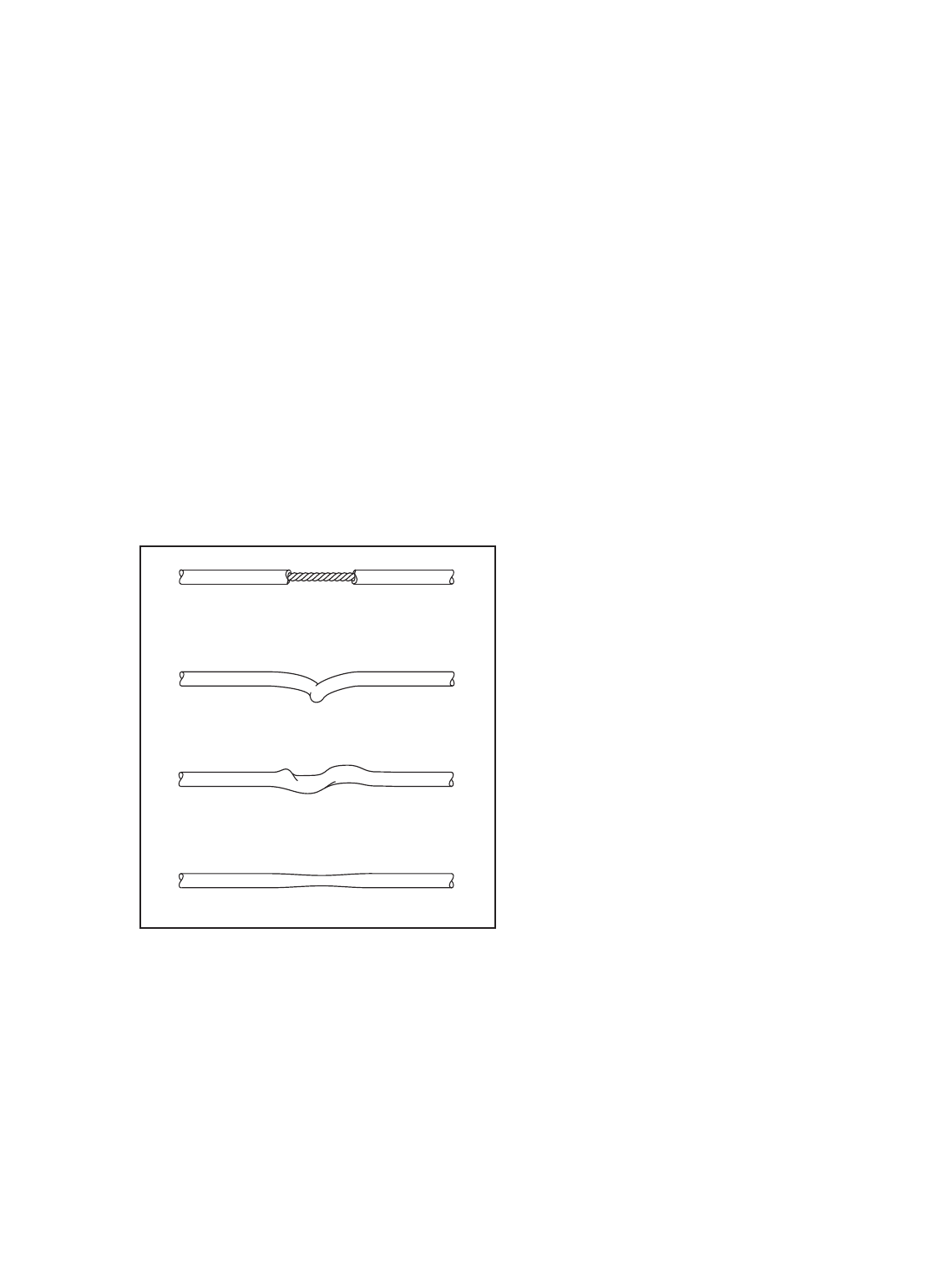
2. Cables:
•Check all cables for proper tension.
•Check the entire length of the cable by pulling
each handle individually to its fully extended
position and inspecting the cable that is
exposed on the exterior of the machine, as well
as the cable inside of the cut stack tower.
•Run your fingers along the cable, paying close
attention at the bends and attachment points.
•Watch for the following conditions, which may
indicate a worn cable in need of replacement:
A. Torn or split cable sheath that exposes the
cable
B. Kinked or severely bent cable
C.Curled or twisted sheath
D.Stretched cable sheath, showing a thinning
cross-section
MONTHLY OR AS REQUIRED
1. Grips:
•Check and replace as needed.
2. Weight Stack Guide Rods:
•Clean and lubricate the full length by wiping
using a soft cloth containing automotive engine
oil. Only a light coating over the entire length is
needed.
CUSHION ATTACHMENT
Important: All FreeMotion Fitness cushions are fabri-
cated using dense plywood with tee-nuts installed for
bolting to the machine framework. Because these tee-
nuts are held by the plywood, they will not withstand
the torque that standard nuts and bolts will. Therefore,
when tightening the cushion bolts, turn them only until
they are snug and the cushion does not move or feel
loose. Overtightening may strip the tee-nuts from the
plywood and make it impossible to remove the cushion
in the future.
CABLE TENSION CHECK
1. Insert the weight pin into the top weight plate.
2. Slowly raise and lower the top weight by normal
machine use. The top weight should come to rest
just on top of the second weight when the handle
is returned to the resting position.
•If there is too much tension on the cable, the top
weight will not rest on the second weight, and it
may be difficult to insert the weight pin into the
weight plates.
•If there is not enough tension on the cable, the
top weight will not be lifted immediately when
one of the handles is pulled. Ideally,the han-
dle/cable should not move more than 1.3 cm
(1/2 in.) from the resting position before the top
weight begins to be lifted.
3. If there is too much or not enough tension on the
cable, adjust the cable as described in CABLE
ADJUSTMENTS, on page 9.
8
A
B
D
C
9
CAUTION: After making any cable adjustment, pull the
handle using a light load and have someone make
sure that the cable is not derailed from a pulley or rub-
bing on a guard (see CABLE GUARDS on page 10).
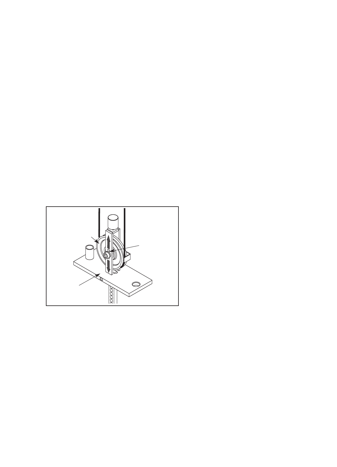
INITIAL ADJUSTMENT
Top Weight Pulley Adjustment—All machines.
Tools required: 9/16” open or box-end wrench, 5/16”
Allen wrench
Note: This is the primary adjustment for all
machines. If this adjustment does not remove the
excess slack, see ADDITIONAL ADJUSTMENTS at
the right.
1. Remove the access cover by pulling it free at the
bottom and then sliding it up until the two sets of
tabs release.
2. Using a 5/16” Allen wrench and a 9/16” open or
box-end wrench, loosen the nut holding the pulley
in the bracket on the top weight.
3. Toincrease the tension, slide the pulley down in
the slot. Todecrease the tension, slide the pulley
up.
4. Tighten the nut and check the tension as
described in CABLE TENSION CHECK on page
8. If necessary, readjust the pulley.
5. Replace the access cover.
ADDITIONAL ADJUSTMENTS
Handle End Adjustment—All machines with a
strap and handle
Tools required: 1/8" Allen wrench, cable cutters,
utility knife, torque wrench
Note: Make this adjustment only if the pulley in the
top weight has been fully adjusted to the bottom of
the slot and the cable requires more tension.
Note: This adjustment is only for increasing the
cable tension because it requires shortening the
cable. Only one end of the cable should be short-
ened.
1. Create slack in the cable by removing the weight
pin and pulling the handle out 15–20 cm (6–8 in.).
Insert the weight pin into the third weight plate
and the tube on the bottom of the top weight.
2. Push the black rubber cover off the aluminum
coupler and slide the cover up the cable to con-
tact the pulley in the swivel arm.
3. Loosen the four oval-point, 1/4-20-unc set screws
in the coupler and pull the cable free.
4. Cut off 2.5 cm (1 in.) of the cable end using cable
cutters. Note: Using any other tool may flatten
or disrupt the end strands so that it may be
difficult to reinsert the cable into the hole of
the coupler.
5. Cut off 2.5 cm (1 in.) of the black cable sheath
from the end of the cable.
6. Reinsert the cable and the sheath into the coupler
so that all of the bare cable is in the hole.
7. Retighten the four set screws into the threaded
holes. Tighten the set screws equally until they
contact the cable. Then, tighten each screw alter-
nately 1/4 turn, until all are set to 85 inch-pounds
(9.6 Newton-meters).
8. Slide the rubber cover over the coupler,remove
the weight pin, and lower the handle.
9. Check for proper tension on the cable as described
in CABLE TENSION CHECK on page 8.
Pulley
Slot
Top Weight
CABLE ADJUSTMENTS
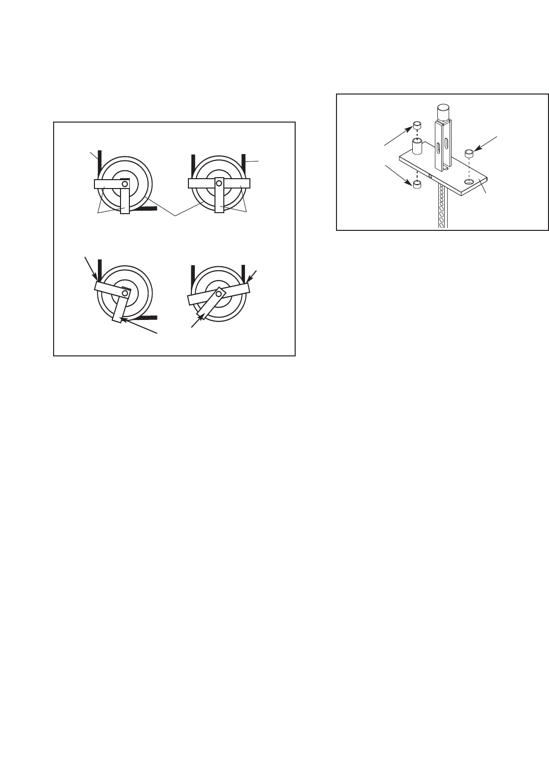
CABLE GUARDS
Check for alignment periodically to ensure that guards
are not dragging on the cable and that they are per-
forming their intended duty. If the alignment is not prop-
er, loosen the bolt slightly and readjust as necessary.
SERVICING THE WEIGHT STACK
For required parts, see HOW TO CONTACT CUS-
TOMER CARE on the back cover of this manual.
1. Remove the access cover by pulling it free at the
bottom and then sliding it up until the two sets of
tabs release.
2. Loosen the top bolt or nuts on each guide rod.
Remove the bolts or nuts and let the guide rods
slide down to the floor.
3. To remove the top weight, first unbolt the pul-
ley(s) to release the cable using a 5/16” allen
wrench/ hex key and a 9/16” open-end
wrench/spanner.
4. Slide the top weight off the top of the guide rods.
Note: Pull the guide rods toward the back of the
machine for increased clearance.
5. Servicing the weight stack involves replacing the
three bushings in the top weight. First, use a
punch to drive the three existing bushings out of
the top weight.
6. To insert the new bushings, hold each bushing
square to the face of one of the holes in the top
weight, place a protective piece of wood on top
of the bushing, and lightly tap the bushing into
place. The bushings should be flush with the sur-
face. Note: There are two sizes of bushings. The
slightly larger bushing is for the single hole in the
top weight; the smaller bushings are for the top
and bottom of the cylindrical standoff.
7. Clean and lubricate the guide rods by wiping
them using a soft cloth containing automotive
engine oil. Apply only a light coating over the
entire length.
8. Replace the top weight on the guide rods. Bolt
the pulley,cable, and cable guards back into
place.
9. Reattach the guide rods to the top of the frame.
10. Insert the weight pin into the top weight. Pull the
handle, lifting the top weight all of the way to the
top. Slowly return the handle to the resting posi-
tion. If the top weight sticks, loosen one of the
guide rod bolts or nuts. Lift the top weight to the
top again. Retighten the guide rod bolt or nuts.
Check the full travel again and readjust the guide
rods if necessary.
11. Whilst slowly pulling the handle, have someone
check the top weight pulley guard to ensure that
it is not dragging or rubbing on the cable.
12. Replace the access cover.
10
Large
Bushing
Small
Bushings
Top
Weight
Correct Alignment
Incorrect Alignment
Rubbing Contacts
Cable
Out of
Alignment
Guards Guards
Cable
Cable
Pulley
11
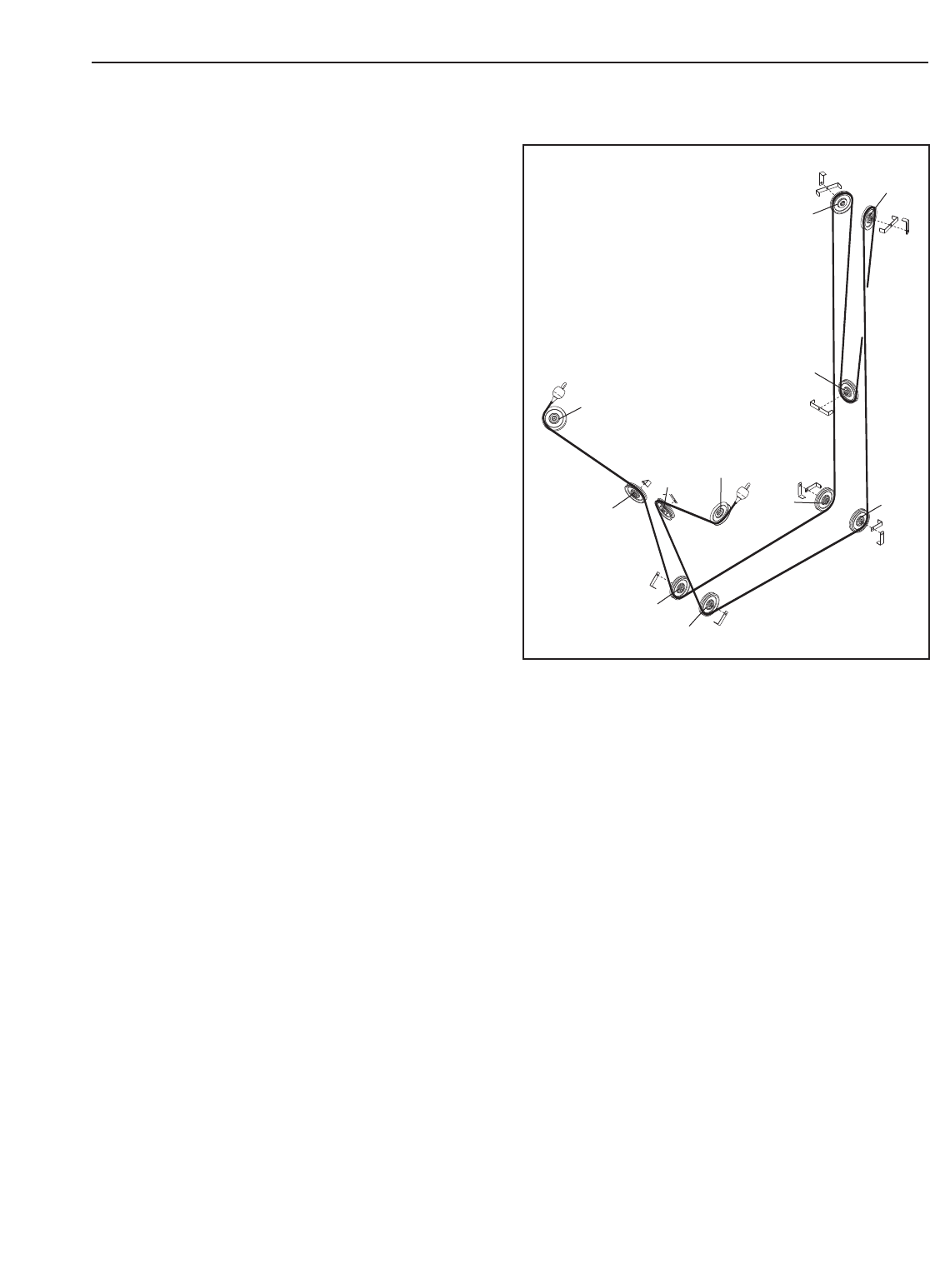
CABLE DIAGRAM
The cable diagram at the right shows the proper route
of the cable. Use the diagram to make sure that the
cable and the cable guards have been assembled
correctly. If the cable has not been correctly routed,
the strength machine will not function properly and
damage may occur. The numbers show the correct
route of the cable. Make sure that the cable guards
do not touch or bind the cable.
1
2
10 11
3
4
5
6
7
8
9

12
Note: “#” indicates a non-illustrated part. Specifications are subject to change without notice.
If replacement parts are needed, or if parts are missing or damaged, see HOW TO CONTACT CUS-
TOMER CARE on the back cover of the owner’s manual.
Key No. Qty. Description Key No. Qty. Description
1 1 Base
21 Tower
3 1 Access Cover
41 Frame Arm
5 2 Swivel Arm
6 1 Seat
7 1 Backrest
8 15 Large Weight
9 1 Top Weight
10 2 Weight Guide Rod
11 1 Right Stabiliser
12 1 Left Stabiliser
13 1 Left Stabiliser Cover
14 1 Right Stabiliser Cover
15 1 Right Tower Cover
16 1 Left Tower Cover
17 1 Upright Cover
18 1 Base Cover
19 3 Floor Bumper
20 11 4 1/2” Pulley
21 10 Large Single Cable Guide
22 3 Large Double Cable Guide
23 2 Weight Bumper
24 2 Small Weight Guide Bushing
25 4 5/8” Lock Washer
26 1 Weight Pin
27 1 Top Weight Bumper
28 4 Pivot Pulley Bearing
29 2 Rubber Cover
30 2 Aluminum Coupler
31 2 Eyebolt
32 4 3/8” x 2” Bolt
33 2 3/8” x 4” Bolt
34 1 Large Weight Guide Bushing
35 2 3/8” x 3 1/2” Bolt
36 4 3/8” x 1” Screw
37 6 3/8” x 1/2” Screw
38 1 3/8” x 2 1/4” Bolt
39 2 Spring Clip
40 2 1/2” x 4 1/2” Bolt
41 11 1/2” x 1” Bolt
42 9 3/8” Nut
43 2 3/8” Serrated Lock Washer
44 2 1” Retainer Ring
45 2 1” Washer
46 2 1” Wave Washer
47 28 Rivet
48 9 Small Weight
49 2 Handle w/Strap
50 8 Cable Set Screw
51 2 1 1/8” Retainer Ring
52 1 Cable
53 4 5/8” Nut
54 2 Trunnion
55 2 Cable Bearing
56 4 3/8” Jamnut
57 2 1” Hole Plug
58 2 3/8” x 1 3/4” Bolt
59 2 Bungee Cord
60 4 Bungee Tie
61 2 Bungee Clip
62 2 #10 x 1/2” Screw
# 1 Owner’s Manual
PART LIST—Model No. GZFM6000.3 R0305A
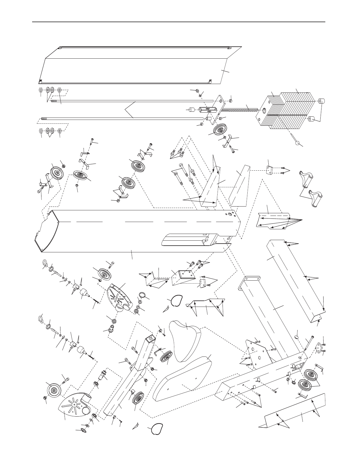
EXPLODED DRAWING—Model No. GZFM6000.3 R0305A
3
26
40 41
41
1
2
4
5
5
6
7
8
9
10
11
12
13
14
15
16
17
18
19
19
19
20
20
20
20
20
20
21
21
22
23
34
24
27
54
28 54 28
58
58
32
32
33
33
41
35
36
36
36
37
37
37
37
38
32
41
41 42
42
42
42
42
42
43
43
44
44
46
46 52 52
51 51
48
49
47
47
47
47
47
47
47
47
47
47
47
47
47
53
53
25
53
53
25
20
21
22 32
42
20
21
22
42
20
20
21
21
35
42
45
45 29
30
31
56
55 56
50
50
29
30
31
56
55
56
50
50
39
39
24
28
28
57
57
21
21
60
59
61
62
61
62 60
59
13

14
NOTES

15
NOTES

Part No. GZ7217 R0305A Printed in USA © 2005 ICON IP, Inc.
HOW TO CONTACT CUSTOMER CARE
If you have questions after reading this manual, or if you require assistance, please contact Customer Care at
the address and phone number listed below. Please be prepared to give the following information:
•The MODEL NUMBER of the product (GZFM6000.3)
• The NAME of the product (FREEMOTION®CHEST strength machine)
• The SERIAL NUMBER of the product (see the front cover of this manual)
When ordering replacement parts, please also give the KEY NUMBER and DESCRIPTION of the part(s) (see
the PART LIST and the EXPLODED DRAWING on pages 12 and 13 of this manual).
Customer Care: 1-800-201-2109, Monday–Friday, 8 a.m.–5 p.m. Mountain Time
FreeMotion Fitness, Inc. • 1096 Elkton, Suite 600 • Colorado Springs, CO 80907
