Freescale Semiconductor WCT-5WTXMULTI Wireless Charger Transmitter User Manual WCT1000 A11 Reference Design System User Guide
Freescale Semiconductor, Inc. Wireless Charger Transmitter WCT1000 A11 Reference Design System User Guide
RUN-WCT-5WTXMULTI_User Manual
Freescale Semiconductor Document Number: WCT1101SYSUG
User Guide Rev. 2, 11/2014
© Freescale Semiconductor, Inc., 2014. All rights reserved.
_______________________________________________________________________
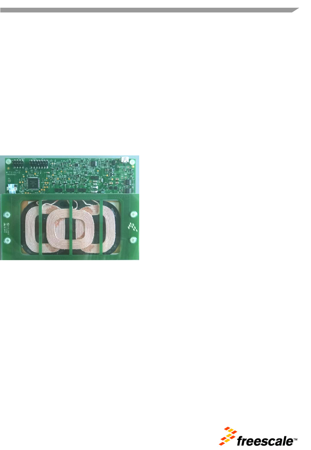
WCT-5WTXMULTI
User Guide
1 Introduction
This document describes how to use 5W low
power wireless charger transmitter WCT-5WTX
MULTI designed by Freescale.
Figure-1 WCT-5WTXMULTI
Contents
1 Introduction 1
2 System Features 2
3 Getting Started 2
4 Cautions 3
WCT-5WTXMULTI Reference Design System User Guide, Rev. 2
2 Freescale Semiconductor
2 System Features
The WCT-5WTXMULTI reference board has following features:
• Reference design compliant with low power WPC Qi version 1.1 Specification.
• Integrated digital demodulation in chip.
• Support multiple types Rx modulation signals (AC capacitor, AC resistor and DC resistor).
• Support FOD. Support four types of Foreign Object protection.
• Support Qi 1.1 receiver with 5 V DC@1A output power capability.
• Super low standby power by Freescale touch technology.
• Full bridge topology with freqency modulation power control strategy.
• LED for RX and TX alignment indication.
• Input voltage/current, coil current sensing for protection.
• Free position charging.
3 Getting Started
WCT-5WTXMULTI is easy to use, and can convenience to charging the mobile equipment that support
the Qi wireless charging, below is the detail step to power up the system and use.
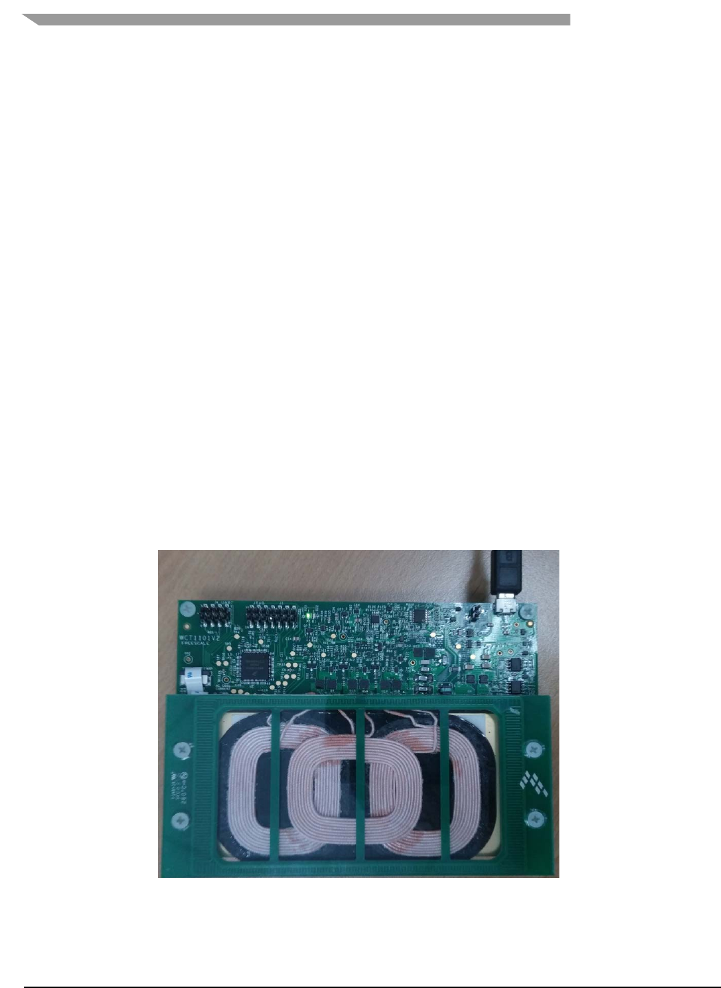
Step 1: power on the Transmitter, plug the 5V adaptor to the AC power line, and plug the adaptor USB
port to the transmitter input port, and the LED2 will be blanking.
Figure-2 WCT-5WTXMULTI powered on
WCT- 5WTXMULTI User Guide
Freescale Semiconductor 3
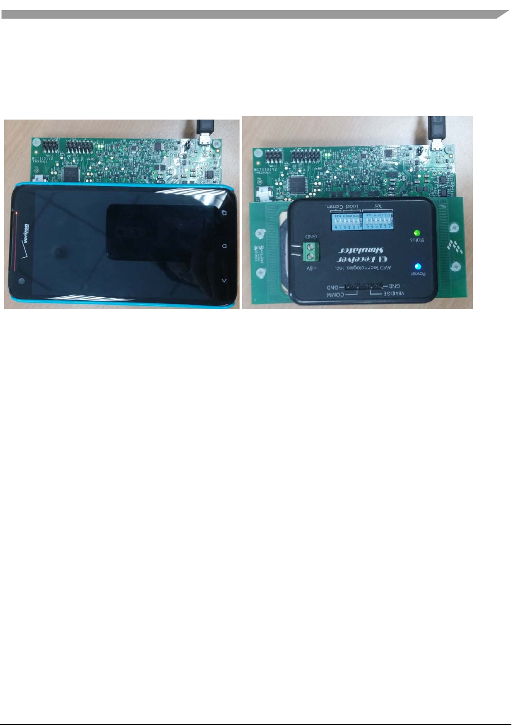
Step 2: Place the wireless charging RX or some equipment that support the Qi wireless charger(such as
cell phone, battery and so on ) on the WCT-5WTXMULTI’s coil surface, then the transmitter will charge
the equipment, under the normal charging states, LED2 will be turned on all the time, and LED1 will be
blanking, and the RX will powered on the equipment normally.
Figure-3 WCT-5WTXMULTI charging the equipments
Others Indicates: when the Transmitter get the end power communication information, it will stop the
charging and wait until the RX is removed, under this states LED1 will be turned off, and LED2 will be
turned on all the time. When some fault found, the transmitter will turn off LED1, and turn on LED2 until
the fault is removed, fault include the FOD fault, OVP, OTP and so on.
DPL mode: when the transmitter is powered by the limited power USB port, the sytem maybe enter the
DPL mode, the cell phone will be charged with limited power.
4 Cautions
• This device has been tested and found to comply with the limits pursuant to Part 18 of the FCC Rules.
These limits are designed to provide reasonable protection against harmful interference in a residential
installation. This equipment generates uses and can radiate radio frequency energy and, if not installed
and used in accordance with the instructions, may cause harmful interference to radio communications.
However, there is no guarantee that interference will not occur in a particular installation.
• If this equipment does cause harmful interference to other electronic equipments, which can be
determined by turning the equipment OFF and ON, the user is encouraged to try to correct the
interference by one or more of the following measures:
• Reorient or relocate the equipment
• Increase the separation
• In order to use the equipment safely,please don’t open the case when powered on,and don’t touch
the PCB and components with hand.

WCT-5WTXMULTI Reference Design System User Guide, Rev. 2
4 Freescale Semiconductor
• Don’t place some metal things between the TX surface and the RX surface, otherwise the metal
things will be heated, it the temperature is too high, the Transmitter will shut down for protection.
This device complies with Part15 of the FCC Rules. Operation is subject to the following
two conditions:
(1) This device may not cause harmful interference, and (2) This device must accept any
interference received, including interference that may cause undesired operation.

Document Number: WCT1101SYSUG
Rev. 2
11/2014
How to Reach Us:
Home Page:
www.freescale.com
Web Support:
www.freescale.com/support
Information in this document is provided solely to enable system and software
implementers to use Freescale products. There are no express or implied copyright
licenses granted hereunder to design or fabricate any integrated circuits based on the
information in this document.
Freescale reserves the right to make changes without further notice to any products herein.
Freescale makes no warranty, representation, or guarantee regarding the suitability of its
products for any particular purpose, nor does Freescale assume any liability arising out of
the application or use of any product or circuit, and specifically disclaims any and all liability,
including without limitation consequential or incidental damages. “Typical” parameters that
may be provided in Freescale data sheets and/or specifications can and do vary in different
applications, and actual performance may vary over time. All operating parameters,
including “typicals,” must be validated for each customer application by customer’s
technical experts. Freescale does not convey any license under its patent rights nor the
rights of others. Freescale sells products pursuant to standard terms and conditions of sale,
which can be found at the following address: freescale.com/SalesTermsandConditions.
Freescale and the Freescale logo are trademarks of Freescale Semiconductor, Inc., Reg.
U.S. Pat. & Tm. Off. All other product or service names are the property of their respective
owners.
©2013 Freescale Semiconductor, Inc.