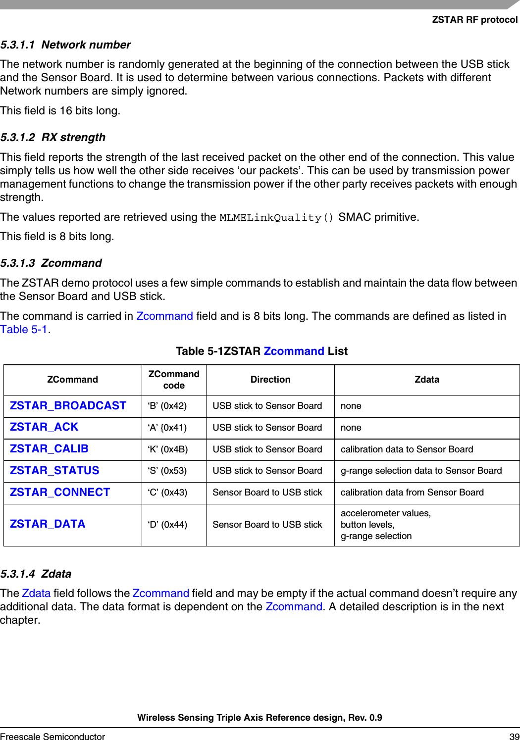
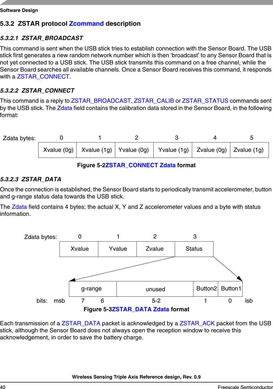
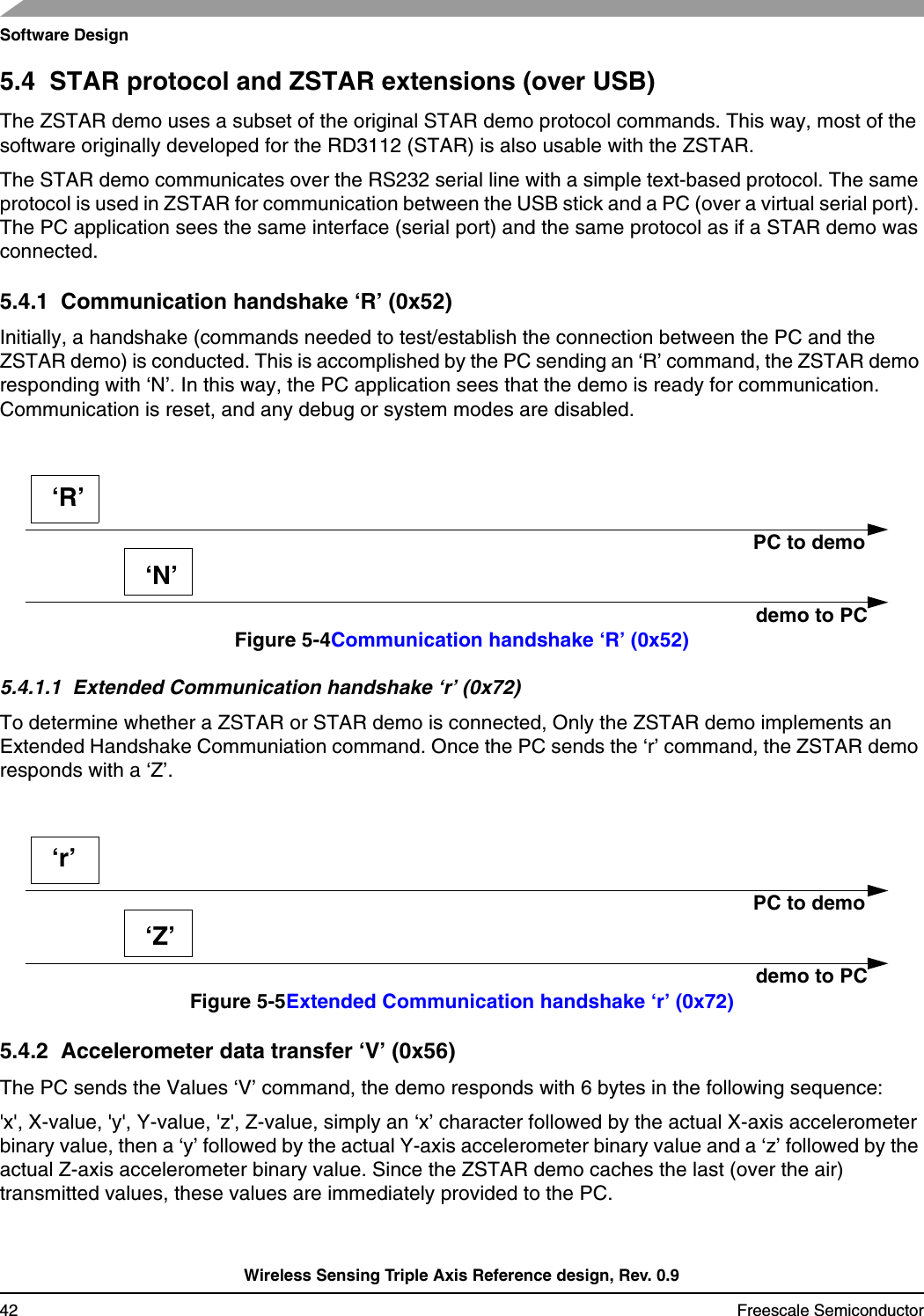
Freescale Semiconductor ZT2 ZStar Triaxial Accelerometer User Manual DRM078
Freescale Semiconductor, Inc. ZStar Triaxial Accelerometer DRM078
UserManual.wiki
>
Freescale Semiconductor
>
ZT2 User Manual
manual
Navigation menu
Upload a User Manual
Namespaces
Wiki Guide
HTML
PDF
Info
Views
User Manual
Discussion / Help
Navigation
![USA:This device complies with Part 15 of the FCC Rules. Operation is subject to the following two conditions: (1) this device may not cause harmful interference, and (2) this device must accept any interferenceCanada:This Class [*] digital apparatus complies with Canadian ICES-003.Cet appareil numériqué de la classe [*] est conformé à la norme NMB-003 du Canada.Europe:TBD Warning: Any changes or modifications to this device not expressly approved by the party responsible forcompliance could void the user's authority to operate the equipment.](https://usermanual.wiki/Freescale-Semiconductor/ZT2/User-Guide-964997-Page-2.png)

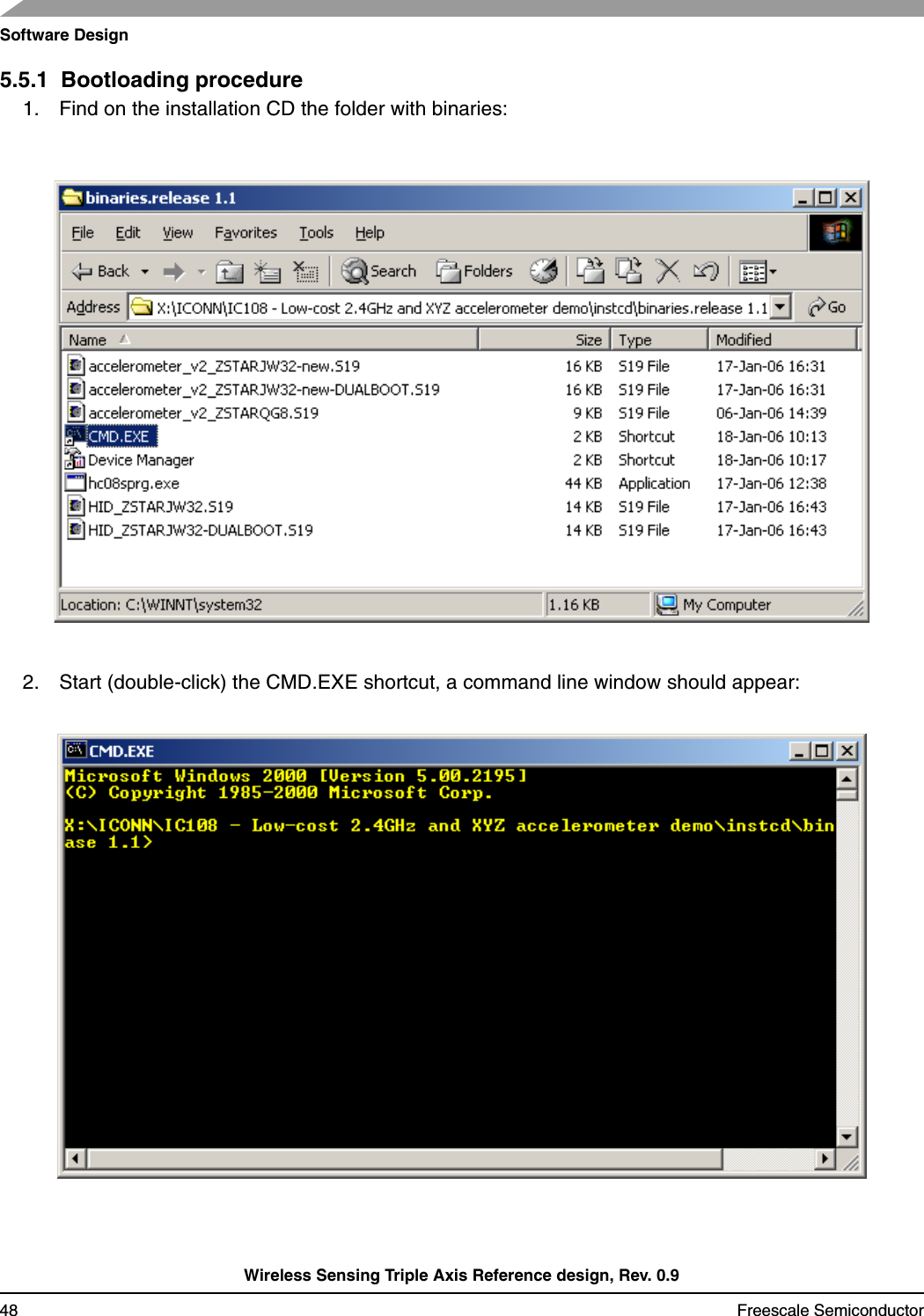
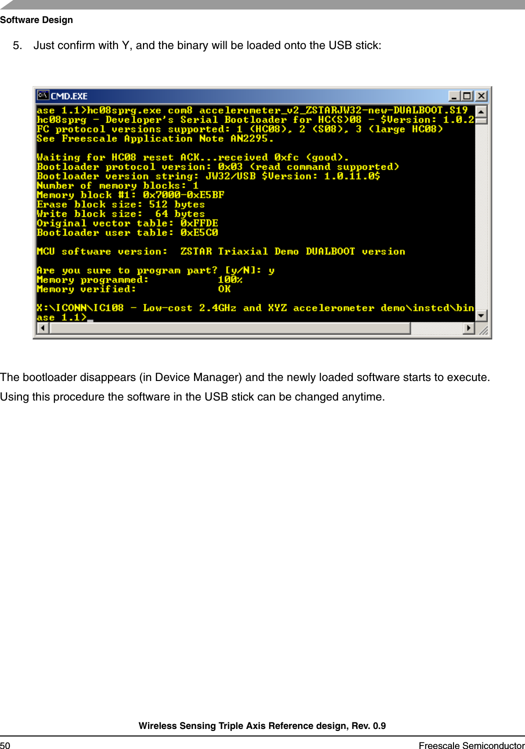
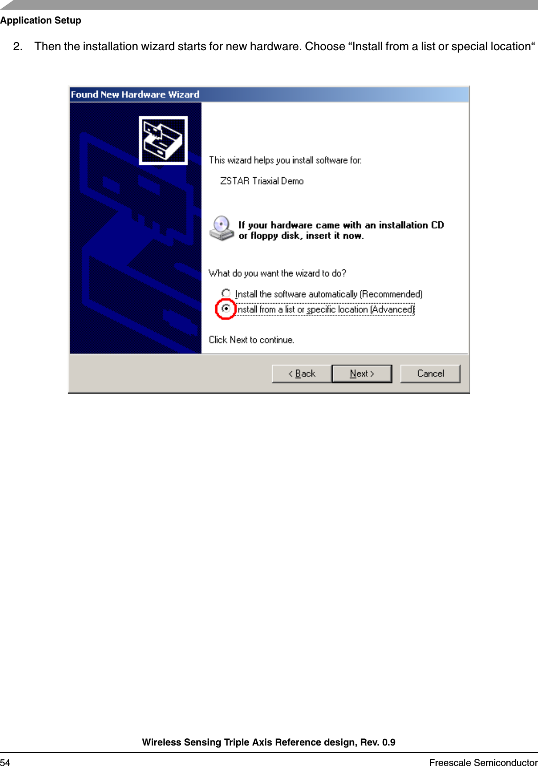
![BootloaderWireless Sensing Triple Axis Reference design, Rev. 0.9Freescale Semiconductor 493. Now type: hc08sprg [bootloader com port number] [binary (S file) that you want to bootload], just like this:hc08sprg.exe com8 accelerometer_v2_ZSTARJW32-new-DUALBOOT.S194. Press ENTER and initial bootloader communication will start:If this screen does not appear, remove the USB stick and start from the beginning.](https://usermanual.wiki/Freescale-Semiconductor/ZT2/User-Guide-964997-Page-49.png)