Freestyle 789 TR35705 User Manual To The F1b08a09 5410 4394 826b 90f38124c199
User Manual: Freestyle 789 to the manual
Open the PDF directly: View PDF ![]() .
.
Page Count: 40
INTELA-TRAUL®
Quality Refrigeration
MASTER SERVICE MANUAL
Form Number TR35705, revised 10/04
Traulsen
4401 Blue Mound Road - Fort Worth, Texas 76106
Phone: (800) 825-8220 or (817) 625-9671
Fax-Service (817) 740-6757
For All Full Size Undercounter, G-Series and
R&A Series Refrigerator, Freezer, Dual-Temp
and Hot Food Unit Controllers
TABLE OF CONTENTS
-1-
I. General Information
a) How To Use This Manual Page 2
b) About INTELA-TRAUL Page 2
c) Operating The Controller Page 2
II. Basic Service Procedures
a) Adjusting The Temperature Page 3
b) Starting A Manual Defrost Cycle (R & A Series) Page 4
c) Starting A Manual Defrost Cycle (G-Series) Page 5
III. Troubleshooting
a) Checking For Defective Sensors Page 6
b) Checking For Failed Relays Page 7
c) Checking For Other Failed Components Page 8
d) Checking For Iced Evaporator Coil Page 9
e) Proper Sensor Placement Page 10
IV. Control Architecture
a) R & A Series Refrigerator & Freezer Vertical Controllers Page 11-14
b) Undercounter Refrigerator & Freezer Horizontal Controllers Page 15
c) G-Series Refrigerator & Freezer Vertical Controllers Page 16-17
d) R & A Series Heated Cabinet Vertical Controllers Page 18-20
V. Removal/Installation
a) All Vertical Controllers Pages 21-22
b) All Horizontal Controllers Page 23
VI. Problem Diagnosis
a) How To Use Troubleshooting Trees Page 24
b) Hi-Temp Alarm (all HT/RI & LT/IF models) Page 25
c) Lo-Temp Alarm (all HT/RI & LT/IF models) Page 26
d) Door Open Alarm (all HT/RI, LT/IF HF/IH models) Page 27
e) Power Loss Alarm (all HT/RI, LT/IF HF/IH models) Page 28
f) System Leak Alarm (all HT/RI & LT/IF models) Page 29
g) Condenserclean Alarm (all HT/RI & LT/IF models) Page 30
VII. Accessing The Engineering Level Page 31
VIII. Control Parameters
a) Parameter Descriptions Page 32-33
b) Parameter Access & Units Of Measurement Page 34
c) G-Series Parameter Settings Page 35
d) R-Series Parameter Settings - Refrigerator Models Page 36
e) R-Series Parameter Settings - Freezer Models Page 37
f) Undercounter Parameter Settings Page 38

I. a - HOW TO USE THIS MANUAL:
Traulsen provides this manual as an aid to the service technician in installation,
operation, and maintenance of INTELA-TRAUL® Controllers. When used
properly, this service manual can help the service technician maintain,
troubleshoot and diagnose most of the problems and malfunctions that may occur
with the Controllers.
This manual covers the four different types of Controllers (Full Size Undercounter,
G-Series, R&A Series Refrigerator & Freezer, and R&A Series Hot Food). These
vary slightly from one another, all exceptions are noted, and where appropriate
separate sections are provided.
While we believe that most aspects of the controllers are covered in this manual,
should you encounter a condition not addressed, or require a wiring diagram please
contact:
All service communication must include:
Model Number & Serial Number Of Unit
A detailed explanation of the problem
Traulsen
4401 Blue Mound Road Fort Worth, TX 76106
Attn: Service Department
Phone: (800) 825-8220 or (817) 625-9671
Fax: (817) 740-6757
-2-
I. GENERAL INFORMATION
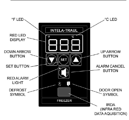
I. b - ABOUT INTELA-TRAUL:
The Traulsen INTELA-TRAUL and G-Series microprocessor controls are
microprocessor based systems which replace several electromechanical
components typically built into refrigeration products, such as: time clocks,
thermometers, defrost limit switches and temperature controls, all combined into
one solid state modular unit.
These microprocessor controls both monitor a cabinet air sensor and a coil
sensor. The INTELA-TRAUL on the R & A Series also includes a discharge line
sensor and a relative humidity sensor (H1 versions only). In conjuction with the
programmed parameters of the control, and the information received, it cycles the
refrigeration system ON and OFF at set temperatures, initiates and/or terminates
defrost cycles, and initiates one of several alarm features if a problem is sensed
(R & A Series only). R & A Series controls also allow the operator to cycle the door
perimeter heaters ON/OFF as needed.
I. c - OPERATING THE CONTROLLER:
When operating the controller it is important to note that you only have
approximately 20-30 seconds between button pushes. If you take longer than 30
seconds, the controller will revert back to displaying the cabinet temperature.If you
enter the wrong security code, the controller will revert back to displaying the
cabinet temperature. You can exit the parameters at any time by waiting 20-30
seconds for the control to return to normal operation.
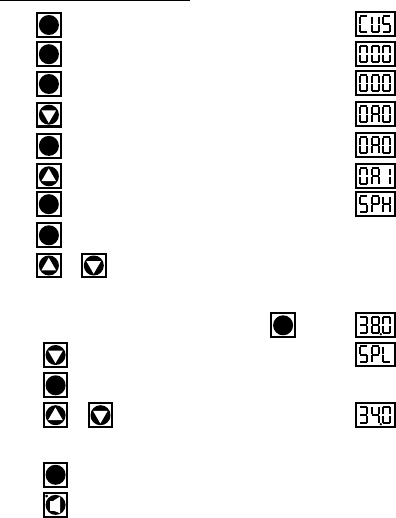
Step 1: Press . Display will read “CUS.”
Step 2: Press . Display will read “000” with the left digit flashing.
Step 3: Press . Display will read “000” with the center digit flashing.
Step 4: Press until the center digit changes to an “A”.
Step 5: Press . Display will read “0A0” with the right digit flashing.
Step 6: Press until the right digit changes to an “1”.
Step 7: Press . Display will read “SPH”.
Step 8: Press again.
Step 9: Press or to adjust temperature to desired setting.
(NOTE: SPH should be set at 38 to 40
°
F for refrigerators and 0
°
F for freezers)
Step 10: When display reads the desired temperature press .
Step 11: Press until display reads “SPL”.
Step 12: Press .
Step 13: Press or to adjust temperature to desired setting.
(NOTE: SPL should be set at 34
°
F for refrigerators and -4
°
F for freezers)
Step 14: Press .
Step 15: Press to exit (R & A Series only). On G-Series models the
controller will automatically revert back to normal temperature display operation
after a delay of approximately 20-30 seconds.
SET
II. BASIC SERVICE PROCEDURES
The Display
Will Read
II. a - ADJUSTING THE TEMPERATURE:
SET
SET
SET
SET
SET
SET
SET
SET
-3-
-4-
II. BASIC SERVICE PROCEDURES
II. b - STARTING A MANUAL DEFROST CYCLE (R & A Series):
The Display
Will Read
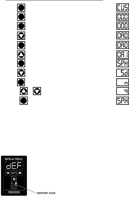
Step 1: Press . Display will read “CUS.”
Step 2: Press . Display will read “000” with the left digit flashing.
Step 3: Press . Display will read “000” with the center digit flashing.
Step 4: Press until the center digit changes to an “A”.
Step 5: Press . Display will read “0A0” with the right digit flashing.
Step 6: Press until the right digit changes to an “1”.
Step 7: Press . Display will read “SPH”.
Step 8: Press until the control reads “Sd,” Start Manual Defrost.
Step 9: Press . Display will read “n” (NO).
Step 10: Press or . Display will read “4” (YES).
Step 11: Press . Controller will display “SPH” for 30 seconds and
then “DEF” will appear.
SET
SET
SET
SET
SET
SET
NOTE:
Traulsen R & A Series refrigerator models also include an off-
cycle defrost feature, which occurs once an hour. This is
indicated by the control display, is time or temperature
terminated, and generally is of 3 - 10 minutes in duration.
NOTE: The controller will automatically revert back to normal operation
after a delay of approximately 20-30 seconds.
SET
-5-
II. BASIC SERVICE PROCEDURES
II. c - STARTING A MANUAL DEFROST CYCLE (G-Series):
The Display
Will Read
NOTE:
Traulsen G-Series refrigerator models also include an off-cycle
defrost feature, which occurs once an hour. This is
indicated by the control display, is time terminated, and is
generally of 3 - 10 minutes in duration.
The defrost cycle on Traulsen G-Series freezer models can
be either time or temperature terminated.
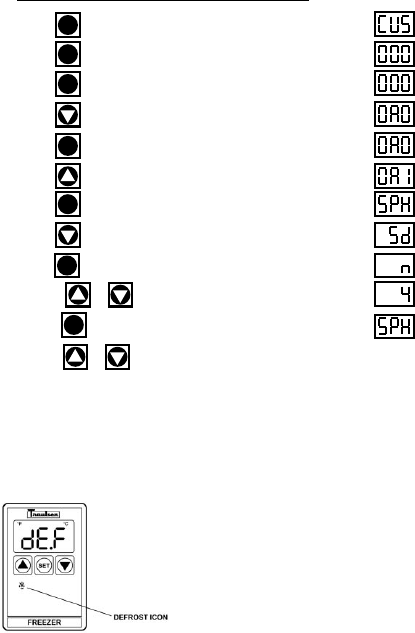
Step 1: Press . Display will read “CUS.”
Step 2: Press . Display will read “000” with the left digit flashing.
Step 3: Press . Display will read “000” with the center digit flashing.
Step 4: Press until the center digit changes to an “A”.
Step 5: Press . Display will read “0A0” with the right digit flashing.
Step 6: Press until the right digit changes to an “1”.
Step 7: Press . Display will read “SPH”.
Step 8: Press until the control reads “Sd,” Start Manual Defrost.
Step 9: Press . Display will read “n” (NO).
Step 10: Press or . Display will read “4” (YES).
Step 11: Press . Display will then read “SPH,” Start Manual Defrost.
Step 14: Press or to scroll to the next parameter, otherwise the
controller will automatically revert back to normal operation after a delay of
approximately 20-30 seconds.
SET
SET
SET
SET
SET
SET
SET
-6-
III. TROUBLESHOOTING
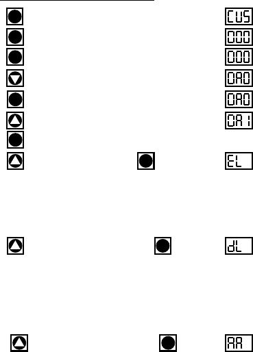
Step 1: Press . Display will read “CUS.”
Step 2: Press . Display will read “000” with the left digit flashing.
Step 3: Press . Display will read “000” with the center digit flashing.
Step 4: Press until the center digit changes to an “A”.
Step 5: Press . Display will read “0A0” with the right digit flashing.
Step 6: Press until the right digit changes to an “1”.
Step 7: Press .
Step 8: Press until display reads “EL”. Press .
If the display now reads “-40,” check for loose connection on the EVAPORATOR
sensor. If the display has a very high reading such as “266,” replace the evaporator
sensor.
NOTE: Erroneous readings may be the result of a faulty sensing circuit (open or
shorted) in the Controller.
Step 9: Press until the display reads “DL1”. Press .
In the event that the display now reads “-40,” check for a loose connection on the
DISCHARGE LINE sensor. If the display has a reading of “220” or higher, check for lack
of adequate air-flow through the condenser, a bad condenser motor, or any other
condition around the unit which could cause a high temperature, such as a steam
table or a crossdraft. Otherwise, proceed with replacing the DISCHARGE LINE sensor.
NOTE: Erroneous readings may be the result of a faulty sensing circuit (open or
shorted) in the Controller.
Step 10: Press until the display reads “AA2”. Press .
Display should read the approximate ambient air temperature behind the louver panel.
If the display reads “111” check for a loose connection on the RH/AMBIENT AIR sensor.
If the display reads “32.0” check the sensor for a short circuit.
NOTE: If display reads -40 or 266 the cabinet sensor is defective and requires
replacement.
NOTE: Ambient Air Sensor not included on MIT version controllers.
NOTE: Erroneous readings may be the result of a faulty sensing circuit (open or
shorted) in the Controller (on H1 control version only).
The Display
Will Read
III. a - CHECKING FOR DEFECTIVE SENSORS:
SET
SET
SET
SET
SET
SET
SET
SET
1= DL is not included on G-Series controllers.
2= AA is not available with MIT version controllers.

-7-
III. TROUBLESHOOTING
III. b - CHECKING FOR FAILED RELAYS:
Checking For A Failed Internal Controller Relay:
1. Gain access to Controller compressor relay (see REMOVAL
INSTRUCTIONS within this service manual for the specific type of
controller your are servicing).
2. Locate the connector with the black/blue/purple wires and unplug it.
Refer to the schematic on the side of the controller, or refer to the
appropriate wiring diagram (to obtain this please contact the factory,
referencing the serial numberof the unit involved).
3. Using a volt/ohm meter (VOM) with the power OFF, check the resistance
across the black to blue wires of the Controller connector. If completed
circuit is indicated (with no power to the Controller), the contacts are
stuck closed and the Controller should be replaced (on MIT versions
either the relay box or one of the other relays within the unit need to be
replaced).
Checking For A Failed External “Slave” Relay or Solid State Relay (SSR),
p/n 337-60360-01 (MIT II Only):
1. Gain access to the controller compressor relay (see REMOVAL
INSTRUCTIONS within this service manual for the specific type of
controller your are servicing).
2. Locate the external “slave” relay and unplug the harness connectors.
3. Using a volt/ohm meter (VOM), check the resistance from the “COM”
terminal to the “NO” terminal. If a completed circuit is indicated, the
contacts are stuck closed and the slave relay should be replaced.
4. For the SSR, remove the black and blue wires from terminals 3 & 4. Using
a volt/ohm meter, and with the power OFF, measure the resistance across
the terminals. A completed circuit indicates that the circuit is closed and
that the relay should be replaced. A reading of 25 mΩ to 35 mΩ is
considered normal for an open circuit in the SSR.
Checking For A Failed Door/Light Relay (R & A Series models only):
1. Gain access to Controller door relay (see REMOVAL INSTRUCTIONS
within this service manual for the specific type of controller your are
servicing).
2. Remove the wire from the door relay coil.
3. Using a volt/ohm meter (VOM), check across the relay contacts. If an
open across the contacts is not indicated, replace the door relay.
NOTE: Equipment manufactured with the MIT II controller version do not
include a Door/Light relay).
4. Physically check the switch for evidence of water. If switch has water in
it, proceed with replacing the switch.
-8-
III. TROUBLESHOOTING
III. c - CHECKING FOR OTHER FAILED COMPONENTS:
Checking For A Failed Door Switch:
1. Remove the door(s) from the unit involved.
2. Locate the door switch, which is located behind the top door hinge(s).
3. Remove the switch from the cabinet.
4. Using a volt/ohm meter (VOM), check across the switch contacts. “COM”
to “NO” should read open. If not, replace the switch.
5. Reinstall the switch and hinge onto the cabinet.
NOTE: If the unit has more than one door, check ALL door switches in the
same manner as described in steps 1 thru 5 above.
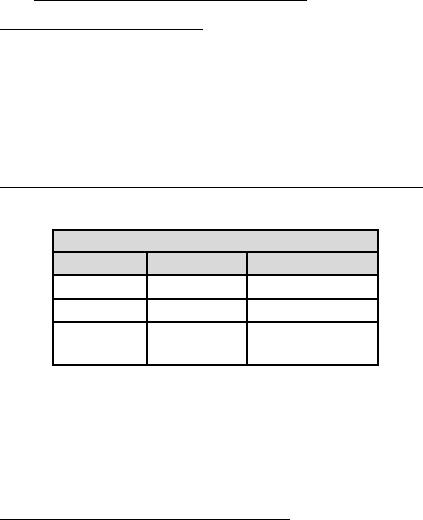
Checking For A Failed Controller Transformer
(H1 & MIT I control versions only)
:
1. Check incoming voltage. Voltage at the unit must be within the ranges
shown in the table below.
2. If the controller display does not come back on, use a volt/ohm meter
(VOM) and check the output voltage of the controller transformer.
3. If the output voltage from the transformer is not within the range
shown in the table above, replace the transformer. If the transformer
tests OK, replace the controller instead.
4. For equipment manufactured with the MIT II controller version the
transformer is mounted inside the relay module. Check between 17 and
8 on 18 pin connector on relay module for 12V DC.
Checking Cabinet, Coil or Discharge Line Sensors:
1. Gain access to CABINET, COIL or DISCHARGE LINE sensor and
disconnect it.
2. Place tip if sensor probe in a mixture of icewater for several minutes.
Allow enough time for sensor probe to aclimate to the icewater.
3. At 32°F, probe resistance shoud be 32.7K Ohms, +/- 10%. If resistance
is not within this range, repalce the sensor.
VOLTAGE
MIN MAX STANDARD
104 VAC 126 VAC 115/60/1
187 VAC 253 VAC 208-230/60/1
10.2 Volts 13.8 Volts Transformer
(MIT 12.4) (MIT 14.7) Output Voltage
Replace
controller*
(see note below).
III. TROUBLESHOOTING
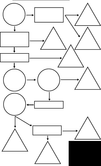
III. d - CHECKING FOR ICED EVAPORATOR COIL:
With
evaporator
clear of ice is
there proper
air-flow?
Check evaporator
blower motor for
proper operation.
Replace
evaporator
blower motor.
Evap’r
or ducting
restriction.
Remove restriction.
Check DEF settings in
controller parameters.
Go to pages 33-36.
Check coil sensors.
Go to pages 6, 7 & 8.
Reset
control
parameters
NO NOT OK
YES
OK
NOT OK
Replace
failed
sensor.
NOT OK
OK
Will unit
enter manual
defrost cycle?
Does
compressor
shut-off in
defrost?
Check defrost heater.
YES
Replace
compressor
relay or module.
NO
YES
Will control
cycle unit at set
temps?
OK
YES
Problem
with ref’n
system.
Check cabinet sensor.
Go to pages 6, 7 & 8.
OK
NOT OK
-9-
Replace
failed
cabinet sensor.
*NOTE: See the corresponding pages to
remove and replace the controller:
•R & A Series Refrigerator & Freezer
Pages 21 - 22.
•G-Series Refrigerator & Freezer
Pages 21 - 22.
•Undercounter Refrigerator & Freezer
Page 23.
•R & A Series Hot Food Cabinets
Pages 21 - 22.
III. TROUBLESHOOTING
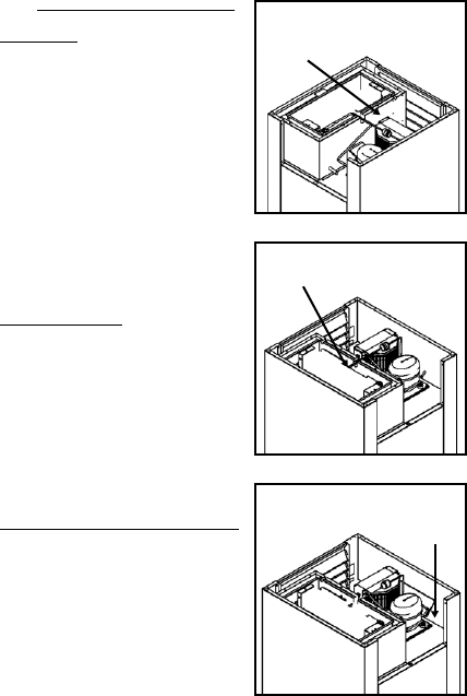
III. e - PROPER SENSOR PLACEMENT:
Coil Sensor:
The coil sensor should be inserted into
the return air side of the evaporator coil.
On freezer models only this sensor
should be centered approximately 2”
(two inches) from the top (horizontally
through coil - centered in coil).
On refrigerator models this sensor
should be mounted on top of the coil.
Cabinet Air Sensor:
The cabinet air sensor should be
mounted inside the evaporator housing
(hump) on the return air side of the
evaporator coil.
Discharge Sensor (R & A Series Only):
The discharge air sensor should be
mounted on the hot gas side of the
compressor. Placement should be as
close to the compressor as possible
and must be placed prior to the
beginning of the hot gas loop. Please
note that discharge sensors must be
insulated.
-10-
Correct
Sensor
Location
Correct
Sensor
Location
Correct
Sensor
Location
-11-
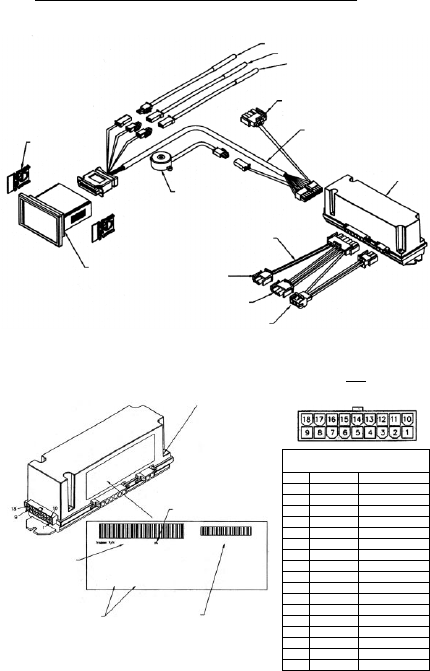
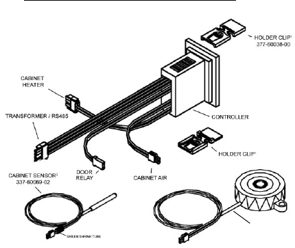
IV. CONTROL ARCHITECTURE
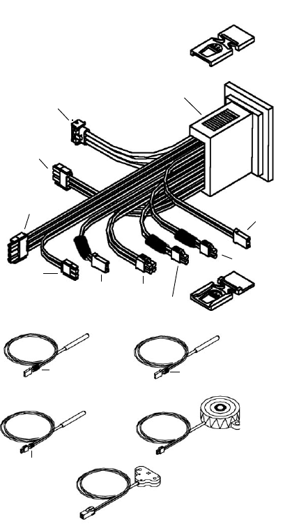
IV. a -
R & A SERIES REFRIGERATOR & FREEZER VERTICAL CONTROLLER:
NOTES: IRDA not included on equipment
manufactured with the MIT II control
version.
See parts assembly on pages 12-13.
-12-
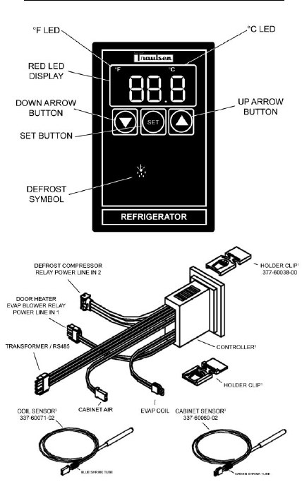
IV. CONTROL ARCHITECTURE
COIL SENSOR3
P/N 337-60071-02
DISCHARGE SENSOR3
P/N 337-60072-00
HORN3
P/N 337-60070-00
CABINET SENSOR3
P/N 337-60069-02
RH SENSOR3
P/N 337-60080-00
(control versions H only)
3= Component can be ordered separately.
HOLDER CLIP1
P/N 337-60038-00
HOLDER CLIP1
P/N 337-60038-00
H1 CONTROLLER2
TRANSFORMER/
RS485
DOOR RELAY
EVAP BLOWER
RELAY
POWER LINE IN 1
DEFROST COMPRESSOR
RELAY POWER LINE IN 2
DOOR
RELAY
CABINET
AIR
HORN
RH/AMBIENT
AIR EVAP
COIL
DISCHARGE LINE
1= Set of two (can be ordered separately).
2= Requires unit model number and serial
number to place order.
BLUE SHRINK TUBE YELLOW SHRINK TUBE
GREEN
SHRINK TUBE
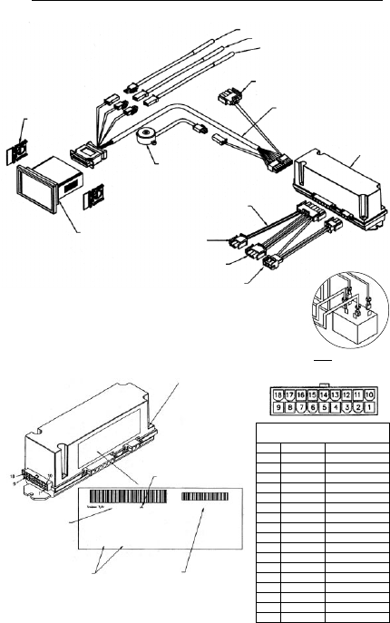
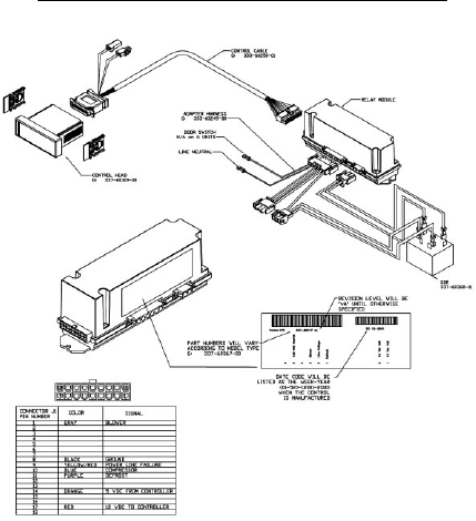
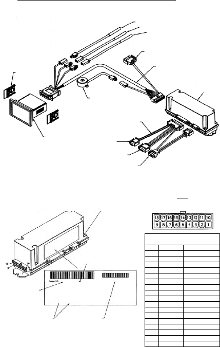
IV. CONTROL ARCHITECTURE
IV. b -
R & A SERIES REFRIGERATOR & FREEZER VERTICAL CONTROLLER:
Parts assembly for H1 thru MIT control versions only
-13-
6 Door Switch
5 Line Neutral
4 Door Heater
3 Blower
2 Line Voltage
1 Defrost
337-60317-00
2 12 VDC Coil
1 12 VDC Coil
DC 12-2001
HOLDER CLIP
337-60038-00
(set of two)
CONTROL HEAD
R/A 337-60318-00
G 337-60319-00
HF 337-60320-00
UC/UL 337-60321-00
HORN
337-60070-00
CABINET SENSOR - 337-60069-02
COIL SENSOR - 337-60071-02
DISCHARGE SENSOR - 337-60072-00
TO TRANSFORMER
(not included for MIT II versions)
CONTROL CABLE
333-60250-00
RELAY BOX
337-60162-02
ADAPTER HARNESS
333-60249-00
TO DOOR RELAY
(door switch & line neutral)
TO DOOR HEATERS
(evap blower relay
power line in 1)
TO COMPRESSOR
& DEFROST RELAY
(power line in 2)
MIT CONTROL TROUBLE SHOOTING DIAGRAM
Date code will be listed
as the week-year (01-52)-
(2001-2100) when the
control is manufactured.
PIN connections may
not be available for
all model types.
Part numbers may
vary according to
model type.
Remove the 4 screws (one
in each corner) & remove
the relay box cover to
expose pin connections &
transformer with voltage
setting jumper.
NOTE
All pins in this connection should
not read more than 20 VAC
Connector
Pin No. Color Signal
1Gray Blower*
2 Orange Door Heater*
3 Green Alarm From Controller
4
5
6 Brown
7White/Purple -RS485
8Black Ground
9Yellow/Red 12 VAC
10 Blue Compressor*
11 Purple Defrost*
12 Yellow Door Open Signal
13 Red Power to Horn
14 Orange
15 White
16 Pink +RS485
17 Red 12 VDC to Controller
18
TO SSR COIL
CIRCUIT (MIT II ONLY)
337-60360-01 - see below
*Voltage should
not be more than
5 DC when
measured to
ground (pin 8).
-14-
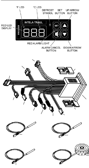
IV. CONTROL ARCHITECTURE
IV. c -
UC & UL (UNDERCOUNTER) HORIZONTAL CONTROLLER:
COIL SENSOR3
P/N 337-60071-02
DISCHARGE SENSOR3
P/N 337-60072-00
HORN3
P/N 337-60070-00
CABINET SENSOR3
P/N 337-60069-02
3= Component can be ordered separately.
BLUE SHRINK TUBE YELLOW SHRINK TUBE
GREEN
SHRINK TUBE
HOLDER CLIP1
P/N 337-60038-00
HOLDER CLIP1
P/N 337-60038-00
HORN
DISCHARGE
LINE
EVAP
COIL
NOT
USED
NOT
USED CABINET
AIR
CONTROLLER2
TRANSFORMER/RS485
DOOR HEATER EVAP
BLOWER RELAY
POWER LINE IN 1
DEFROST COMPRESSOR
RELAY POWER LINE IN 2
1= Set of two (can be ordered separately).
2= Requires unit model number and serial
number to place order.
-15-
IV. CONTROL ARCHITECTURE
IV. c -
UC & UL (UNDERCOUNTER) HORIZONTAL CONTROLLER:
Parts assembly for MIT control version only
HOLDER CLIP
337-60038-00
(set of two)
CONTROL HEAD
UC/UL 337-60321-00
HORN
337-60070-00
CABINET SENSOR - 337-60069-02
COIL SENSOR - 337-60071-02
DISCHARGE SENSOR - 337-60072-00
TO TRANSFORMER
(not included for MIT II versions)
CONTROL CABLE
333-60228-00
RELAY BOX
337-60172-02
ADAPTER HARNESS
HT = 333-60240-00
LT = 333-60225-00
UNUSED
EVAP BLOWER RELAY
(power line in 1)
TO COMPRESSOR
& DEFROST RELAY
(power line in 2)
6 Door Switch
5 Door Switch
4 Door Heater
3 Blower
2 Line Voltage
1 Defrost
337-60172-02
2 Compressor
1 Line Voltage
DC 12-2001
MIT CONTROL TROUBLE SHOOTING DIAGRAM
Date code will be listed
as the week-year (01-52)-
(2001-2100) when the
control is manufactured.
PIN connections may
not be available for
all model types.
Part numbers may
vary according to
model type.
Revision Level
Remove the 4 screws (one
in each corner) & remove
the relay box cover to
expose pin connections &
transformer with voltage
setting jumper.
NOTE
All pins in this connection should
not read more than 20 VAC
Connector
Pin No. Color Signal
1Gray Blower*
2 Orange Door Heater*
3 Green Alarm From Controller
4Black Return From Horn
5
6
7White/Purple -RS485
8Black Ground
9White 12 VAC
10 Blue Compressor*
11 Purple Defrost*
12 Yellow Door Open Signal
13 Red Power to Horn
14
15
16 Pink +RS485
17 Red 12 VDC to Controller
18 Black 12 VAC
*Voltage should not be more than 5 DC when
measured to ground (pin 8).
-16-
IV. CONTROL ARCHITECTURE
IV. d -
G-SERIES REFRIGERATOR & FREEZER VERTICAL CONTROLLER:
-17-
IV. CONTROL ARCHITECTURE
IV. d -
G-SERIES REFRIGERATOR & FREEZER VERTICAL CONTROLLER:
-18-
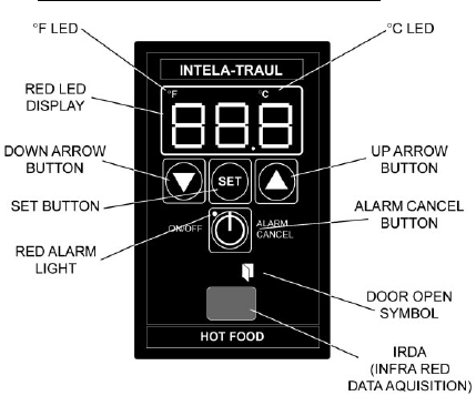
IV. CONTROL ARCHITECTURE
IV. e -
R-SERIES HEATED CABINET VERTICAL CONTROLLER:
HOT FOOD CABINET START-UP (pre-MIT version):
When power is first applied to the unit, you must set the temperature by pressing
the “SET” and “UP ARROW” buttons at the same time using equal pressure with
both thumbs, until the temperature appears on the display. Next, use the “UP”
button to reach the desired temperature (maximum 180°), then press and release
the “SET” button to lock it in.
After this is done you can turn the control ON and OFF by pressing and releasing
the “ALARM CANCEL” button.
Be aware to watch for the display constantly reading “OFF”. This is an indication of
a possible faulty cabinet sensor. To remedy, replace the sensor and reset the
operating temperature.
HOT FOOD CABINET START-UP (MIT version):
The MIT control offers an additional means of turning the cabinet heaters ON and
OFF. After the operating temperature has been set, the operator can continuously
turn the unit OFF and then back ON again to the same operating temperature by
pressing the “ON/OFF” button on the face of the control.
Please note that this feature will not function if the control is in an alarm state with
the alarm LED illuminated.
NOTES: IRDA not included on equipment
manufactured with MIT II control
version.
See parts assembly on pages 17-18.
2
1= Set of two (can be ordered separately).
2= Requires unit model number and serial
number to place order.
-19-
IV. CONTROL ARCHITECTURE
HORN
337-60070-001
IV. e -
R-SERIES HEATED CABINET VERTICAL CONTROLLER:
Parts assembly for H1 control versions only
-20-
IV. CONTROL ARCHITECTURE
IV. e -
R-SERIES HEATED CABINET VERTICAL CONTROLLER:
Parts assembly for MIT control versions only
HOLDER CLIP
337-60038-00
(set of two)
CONTROL HEAD
HF 337-60320-00
HORN
337-60070-00
CABINET SENSOR - 337-60069-02
UNUSED
TO TRANSFORMER
(not included for MIT II versions)
CONTROL CABLE
333-60228-00
RELAY BOX
337-60171-02
ADAPTER HARNESS
333-60225-00
TO DOOR RELAY
UNUSED
TO HEATERS
UNUSED
6 Door Switch
5 Line Neutral
4 Door Heater
3 Blower
2 Line Voltage
1 Defrost
337-60371-00
2 12 VDC Coil
1 12 VDC Coil
DC 12-2001
MIT CONTROL TROUBLE SHOOTING DIAGRAM
Date code will be listed
as the week-year (01-52)-
(2001-2100) when the
control is manufactured.
PIN connections may
not be available for
all model types.
Part numbers may
vary according to
model type.
Revision Level
Remove the 4 screws (one
in each corner) & remove
the relay box cover to
expose pin connections &
transformer with voltage
setting jumper (MIT II
version only).
NOTE
All pins in this connection should
not read more than 20 VAC
Connector
Pin No. Color Signal
1Gray Blower*
2 Orange Door Heater*
3 Green Alarm From Controller
4Black Return To Horn
5
6
7White/Purple -RS485
8Black Ground
9White 12 VAC
10 Blue Compressor*
11 Purple Defrost*
12 Yellow Door Open Signal
13 Red Power to Horn
14
15
16 Pink +RS485
17 Red 12 VDC to Controller
18 Black 12VAC
*Voltage should
not be more than
5 DC when
measured to
ground (pin 8).
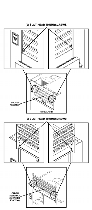
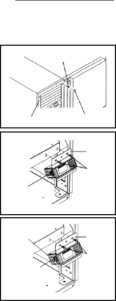
V. REMOVAL/INSTALLATION
V. a -
ALL VERTICAL CONTROLLERS:
To remove INTELA-TRAUL® (p/n’s 337-60090-00, 337-60091-00 and
337-60092-00) and G-Series (p/n’s 337-60093-00, 337-60094-00 and
337-60095-00) Vertical Controller from the unit in which it is installed, proceed as
follows (If unable to access the unit from the rear perform steps 1 through 3,
otherwise, proceed to step 4):
-21-
1. At front of unit,
remove two (2)
slot head thumb
screws from
bottom corners of
louver
assembly. Set
thumbscrews
aside.
2. Swing louver
assembly up and
away from front of
unit until it stops.
3. Remove two (2)
Slot head thumb-
screws from top of
louver assembly.
Set thumbscrews
and louver
assembly aside.
-22-
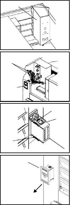
V. REMOVAL/INSTALLATION
4. At the top of the junction box,
remove three (3) Phillips head
screws. Set screws aside.
5. Locate one (1) Phillips head
screw at bottom of junction box,
and remove. Set screw aside.
6. Carefully slide junction box
away from front of unit until all
wiring and connections to the
controller are exposed.
7. Locate all nine (9) Controller
connections (five for G-Series),
then carefully disconnect each
one.
8. Firmly grasp and compress the
rounded portion of the middle
prong on each holder clip.
Slowly slide each holder clip off
the controller. Set clips aside.
9. Slowly pull Controller through
mounting hole and set aside.
WARNING: DISCONNECT ALL POWER BEFORE PROCEEDING
TO RE-INSTALL CONTROLLER,
REVERSE THE PRECEEDING
PROCEDURE.
NOTE:
Be sure ALL components
have been disconnected
from the Controller before
performing the next step.
CONTROLLER
PULL CONTROLLER
IN THIS DIRECTION
(3) PHILLIPS
HEAD SCREWS
(1) PHILLIPS
HEAD SCREW
JUNCTION
BOX
REAR VIEW
OF UNIT
CONNECTIONS
CONTROLLER
JUNCTION
BOX
(relay junction
box shown
turned 90
degrees)
MIDDLE
PRONG
HOLDER
CLIP
HOLDER
CLIP
-23-
V. REMOVAL/INSTALLATION
V. a -
ALL HORIZONTAL CONTROLLERS:
To remove INTELA-TRAUL® (p/n’s 337-60096-00 and 337-60097-00) Horizontal
Controller from the unit in which it is installed, proceed as follows:
1. Check to make sure that the
power cable is disconnected
from the wall.
2. Remove the four (4) black
plugs that are located in each
corner of the power pack
louver assembly. Set plugs
aside.
3. Remove the four (4) Phillips
head screws holding the louver
assembly in place. Set screws
and louver assembly aside.
4. Remove the two (2) Phillips
head screws thathold the
Controller and the bracket
assembly to the condenser fan
assembly. Set screws aside.
5. Locate all nine (9) Controller
connections, then carefully
disconnect each one.
6. Firmly grasp and compress the
rounded portion of the middle
prong on each holder clip.
Slowly slide each holder clip off
the Controller. Set clips aside.
WARNING: DISCONNECT ALL POWER BEFORE PROCEEDING
TO RE-INSTALL CONTROLLER,
REVERSE THE PRECEEDING
PROCEDURE.
(4) PHILLIPS
HEAD SCREWS
LOUVER ASSEMBLY (4) BLACK PLASTIC
PLUGS
MOUNTING
BRACKET
(2) PHILLIPS
HEAD SCREWS
MIDDLE
PRONG OF
HOLDER CLIP
(one on each side
of the controller)
MIDDLE
PRONG OF
HOLDER CLIP
(one on each side
of the controller)
MOUNTING
BRACKET
(2) PHILLIPS
HEAD SCREWS
GUIDE SLOTS
(one on each side
of the controller)
-24-
VI. PROBLEM DIAGNOSIS
QUESTION CHECK SOLUTION
VI. a - HOW TO USE THE TROUBLESHOOTING TREES:
The troubleshooting trees on the following pages were developed as an aid to the
service technician in determining the exact solution to a certain problem or mal-
function. When used as designed, the troubleshooting trees can lead you from a
general symptom to the most likely component to suspect as the cause of the
problem.
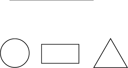
The trees are made up of three different types of boxes:
QUESTION
Boxes ask a yes/no question and the answer will lead to either another question
box, a check box, or a solution box.
CHECK
Boxes will suggest a point to check for proper operation, and will often refer you to
a page in either the SERVICE INFORMATION or the REMOVAL/INSTALLATION
sections of this manual. The result of the check may lead to another box, or a
solution box.
SOLUTION
Boxes suggest the most likely component to cause the malfunction described in
the heading of the tree. When reaching a solution box, do not immediately
assume the component is defective. The final step is to use the SERVICE
INFORMATION section of this manual to verify that the component is defective.
To use the troubleshooting trees, first find the page with the heading describing the
type of problem occurring. Begin at the top of the page and follow the tree,
step-by-step. When a check box is reached, refer to the suggested section to
make the check suggested. Once a solution box is reached, refer to the
suggested section to verify that the component in the solution box is indeed
defective, and repair or replace per the direction in that section.
-25-
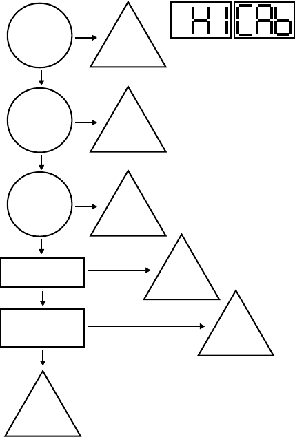
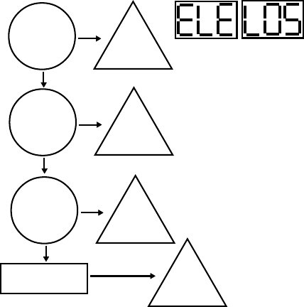
VI. b- HIGH TEMPERATURE ALARM
Door(s) open
longer than 5
minutes?
Check compressor
for low refrigerant.
YES
NO
Close
door(s).
Excessive
amount of hot
product placed
in unit?
YES
NO
Reduce
volume of
hot product.
Is evaporator
coil frozen up?1
YES
NO
Defrost
evaporator
coil.
IS OK
Check that sensor
probe(s) properly
connected.
YES
IS NOT OK
Add
refrigerant.
IS NOT OK
Connect
probe(s).
Replace
failed
sensor.
1= See procedure on page 9.
-26-
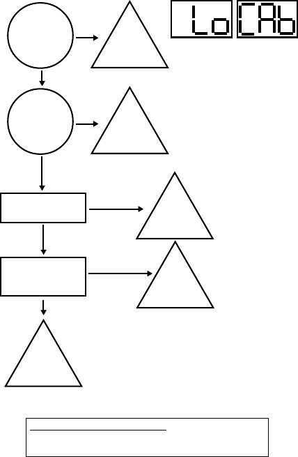
VI. c- LOW TEMPERATURE ALARM
Is temperature
setting for unit
too low?
Check for failed
compressor relay.
YES
NO
Increase
operating
temperature.
Is there food
product in the
unit?
YES
NO
Add
product
to the unit.
IS NOT OK
Replace
failed
controller or
slave relay.
IS OK
Check that sensor
probe(s) properly
connected.
YES
IS NOT OK
Replace
failed
sensor.
Connect
probe(s).
NOTE ON HOT FOOD UNITS ONLY
Hot food units are designed to hold hot food at set temperature.
The cabinet is not designed to heat cold products.
-27-
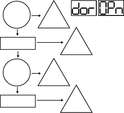
VI. d- DOOR OPEN ALARM
Checkfor a failed door/
light relay.2
Door(s) open
longer than 5
minutes?1
YES
NO
Close
door(s).
IS OK
IS NOT OK
Replace
failed
relay.
Check for mis-wired
door switch.
Is there water
in the door
switch?
YES
NO
Replace
door
switch.
IS NOT OK
Replace
door
switch.
1= H1 and MIT 1 control versions only.
2= See procedure on page 7.
-28-
VI. e- POWER LOSS ALARM
Is unit
plugged
in?
NO
YES
Plug
unit in.
Has unit
suffered a loss
of power due to
bad weather?
YES
NO
Full
operation
will return
when service
is restored.
Is unit
receiving low
voltage input?
YES
NO
Contact
local utility
provider.
Check for failed
controller transformer.1
IS NOT OK
Replace
controller
transformer.
1= See procedure on page 8.
-29-
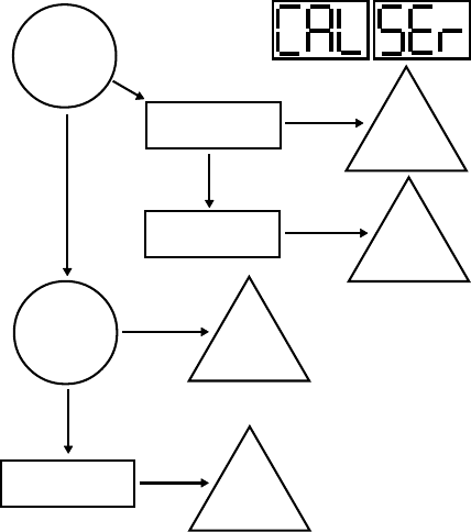
VI. f- SYSTEM LEAK ALARM
Does
discharge temp
rise 45°F within
5 min. of a ref’n.
cycle start?
NO
YES
Add
refrigerant.
Check compressor
for low refrigerant.
IS OK
Check discharge
line sensor.1Replace
failed
sensor.
IS NOT OK
IS NOT OK
Are sensor
probes properly
connected?
YES
Check for disolocated
sensor probe(s).
YES
NO
Connect
Probes.
Relocate
probe(s) to
proper position.
1= See procedure on page 8.
-30-
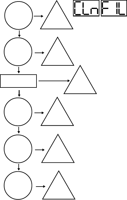
VI. g - CONDENSERCLEAN ALARM
Is
condenser
coil dirty?
YES
NO
Clean
condenser
coil.
Is
condenser fan
disconnected?
YES
NO
Properly
conenct fan.
Check forfailed
condenser fan.
IS NOT OK
Replace
fan.
Are there
any obstructions
at top or rear
of unit?
YES
NO
Remove
obstructions.
Is the room
temperature
too warm?
YES
NO
Lower
the room
temperature.
Is air-flow
restricted by
any objects?
YES
Move
unit or
objects for
better air-flow.
OK
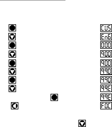
Step 1: Press . Display will read “CUS.”
Step 2: Press until “EnG” is displayed.
Step 3: Press . Display will read “000” with the left digit flashing.
Step 4: Press until the left digit changes to an “9”.
Step 5: Press . Display will read “900” with the center digit flashing.
Step 6: Press until the center digit changes to an “9”.
Step 7: Press . Display will read “990” with the right digit flashing.
Step 8: Press until the right digit changes to an “E”.
Step 9: The display will read (99E), press .
Step 10: Press . The display will now read “FOC” - See Note.
NOTE: R & A Series Only, for G-Series models press for the
control to display “FOC.”
SET
The Display
Will Read
SET
SET
SET
SET
-31-
VII. ACCESSING THE ENGINEERING LEVEL
VII. a - ACCESSING THE ENGINEERING LEVEL:
Not all control parameters can be adjusted at the customers level of access.
To adjust these other parameters it is first necessary to gain access to the
ENGINEERING LEVEL. Please follow the below procedure in order to enter
this level.

FOC 3-digit code which identifies the .hex file loaded at the factory.
ADR Device address for NAFEM networks.
BAU Communications rate when connected into a NAFEM network.
NAF Allow the control to communicate with a NAFEM network.
SPH High value of desired cabinet temperature range.
SPL Low value of desired cabinet temperature range.
SHL Lowest temperature of allowed range for setting of SPH.
SHH Highest temperature of allowed range for setting of SPH.
SLL Lowest temperature of allowed range for setting of SPL.
SLH Highest temperature of allowed range for setting of SPL.
RO Difference, in degrees, between displayed & measured temperature.
HI The highest temperature the cabinet air temperature is allowed to reach before
triggering a High-Temp alarm.
LO The lowest temperature the cabinet air temperature is allowed to reach before
triggering a Low-Temp alarm.
SCL Sets the temperature display scale (fahrenheit or celsius).
HAD Time, in minutes, that the controller delays triggering the High-Temp alarm at any
start-up or at the end of a defrost cycle.
LAD Time, in minutes, that the controller delays triggering the Low-Temp alarm if
cabinet air temperature equal or below SPL setting.
AC The amount of time, in minutes, that the compressor must be off between cycles.
DEF Defines the type of heat used to defrost the coil: Electric, Hot Gas, None or
Off-Cycle.
IBD The amount of time, in hours, between the end of the drip time& start of the next
defrost cycle.
DDC The maximum amount of time, in minutes, that the heat will be on during a defrost
cycle.
CDE The temperature of the evaporator coil that indicates the end of a defrost heat
cycle.
DDE The amount of time, in minutes, between the defrost heat being turned off and the
compressor turning on.
BDD The delay time, in minutes, between the end of the drip time and and before the
evaporator blower turns on.
BSD The temperature of the evaporator coil that triggers the evaporator blower to turn
on after drip time ends.
ODD The maximum amount of time, in minutes, that the display will read the last
temperature recorded before entering the defrost cycle.
SD Allows a techinician to start or stop a defrost cycle.
CFA Alows the customer to turn the clogged filter alram ON/OFF ( R & A Series only).
CCR The minium amount of time, in minutes, that the compressor must be running
before generating a clogged filter alarm.
CDL The discharge line temperature that will trigger a clogged filter alarm.
DOA Allows the customer to turn the door open alarm ON/OFF in units equipped with
the appropriate hardware.
DAD The time, in minutes, that a door must be open before triggering a door open
alarm.
-32-
VIII. CONTROL PARAMETERS
VIII. a - PARAMETER DESCRIPTIONS:

-33-
APD The amount of time, in seconds, that a visual alarm text will be displayed.
ATD Alarm temperature delay.
AAS Allows the customer to set the type of audible alarm style, either Blast, OFF or
Continuous.
CL Allows the customer to set the time of day.
DAY Allows the customer to set the date.
DS Sets daylight savings time On or OFF.
DL1 Selects the time to start a defrost lockout.
DL2 Selects the time to start a defrost lockout.
DL3 Selects the time to start a defrost lockout.
DL4 Selects the time to start a defrost lockout.
DCF Allows the customer to set the percentage of time that the door perimeter heaters
will operate, to control surface condensation.
CON The amount of time the compressor will run in the event of a cabinet air sensor
failure.
COF The amount of time, in minutes, that the compressor will be OFF in the event of a
cabinet air sensor failure.
EL Displays the evaporator temperature at the time (press set or the up arrow button
to display this feature).
DL Displays the discharge line temperature at the time (press set or the up arrow
button to display this feature).
CB When activated (by pressing the set or up arrow buttons), will display the cabinet
air temperature at the time the button is pressed.
PLn When activated will display the approximate line voltage.
RCO Will energize the compressor relay for 10 seconds when activated.
RdF Will energize the heater relay for 10 seconds when activated.
RFA Will energize the blower relay for 10 seconds when activated.
RDH Will energize the door heater relay for 10 seconds when activated.
Pro Parameter used only when reflashing the program memory.
CEP When activated, will return all of the parameters to the initial factory settings.
REF Displays the revision level of the software loaded into memory.
VIII. CONTROL PARAMETERS
VIII. a - PARAMETER DESCRIPTIONS (continued):

VIII. CONTROL PARAMETERS
VIII. b - PARAMETER ACCCESS & UNITS OF MEASUREMENT:
Control Unit of
Parameter Description Access Measure
ADR* Device Address ENG
BAU* Comm. Baud Rate in K ENG KBaud
NAF* NAFEM Communications Enable ENG On/Off
SPH Temperature Set-Point High CUS Degree
SPL Temperature Set-Point Low CUS Degree
SHL Set-Point High/Low ENG Degree
SHH Set-Point High/High ENG Degree
SLL Set-Point Low/Low ENG Degree
SLH Set-Point Low/High ENG Degree
RO Room Offset CUS Degree
HI Upper Temperature Limit ENG Degree
LO Lower Temperature Limit ENG Degree
SCL Temperature Scale CUS F or C
HAD High-Temperature Alarm Delay ENG Minute
LAD Low-Temperature Alarm Delay ENG Minute
AC Anticylcing ENG Minute
DEF Defrost Type ENG Electric/Gas/Off
IBD Intervals Between Defrosts ENG Hours
DDC Maximum Defrost Duration ENG Minute
CDE Coil Temperature At End of Defrost Cycle ENG Degree
DDE Drip Time At End of Defrost Cycle ENG Minute
BDD Blower Delay At Drip Time ENG Minute
BSD BSD After Defrost End ENG Degree
ODD Display Hold After Defrost ENG Minute
SD Start/Stop Defrost CUS Start/Stop
CFA Clogged Filter Alarm n/a On/Off
CCR Clogged Filter Compressor Run Time n/a Minute
CDL Clogged Filter Alarm Temperature n/a Degree
DOA Door Open Alarm ENG On/Off
DAD Door Display Alarm Delay ENG Minute
APD Alarm Pause Delay ENG Second
ATD Alarm Temperature Delay ENG Second
AAS Audible Alarm Style CUS On/Off
CL Set The Clock Time CUS H/N/S
DAY Set The Clock Date CUS Y/N/D
DS Daylight Savings CUS On/Off
DL1 Defrost Lockout 1 CUS Time/Off
DL2 Defrost Lockout 2 CUS Time/Off
DL3 Defrost Lockout 3 CUS Time/Off
DL4 Defrost Lockout 4 CUS Time/Off
DCF Dewpoint Correction Factor CUS %
CON Compressor Default On Time ENG Minute
COF Compressor Off Time ENG Minute
EL Evaporator Coil Temperature CUS Degree
DL Discharge Line Temperature CUS Degree
CB Cabinet Air Temperature CUS Degree
PLn* Display Line Voltage ENG Volts
RCO* Cycle Compressor Relay ENG On/Off
RdF* Cycle Defrost Relay ENG On/Off
RFA* Cycle Blower/Fan Relay ENG On/Off
RDH* Cycle Door Heater Relay ENG On/Off
PRO* Go To Bootloader For Programming ENG
CEP* Clear EEPROM & Load Defaults ENG
REF* Software Version/Revision/Step n/a
-34-
H1, MIT I & MIT II CONTROL VERSIONS ONLY
*MIT II control version only.

-35-
VIII. c - G-SERIES PARAMETER SETTINGS (MIT II Control Version):
Control Freezer Models Refrigerator Models
Parameter GF1 GF2 GF3 GF4 GR1 GR2 GR3
ADR* 2 2 2 2 2 2 2
BAU* 9.6 9.6 9.6 9.6 9.6 9.6 9.6
NAF* ON ON ON ON ON ON ON
SPH -5.2 0.1 0.1 32 38.1 39.2 39.2
SPL -10 -4 -4 26.1 34 37 37
SHL -8 -3.1 -3.1 30.2 36 39.2 39.2
SHH -5.2 0.1 0.1 34 40 40 40
SLL -13 -6.2 -6.2 26.1 32 34 34
SLH -10 -4 -4 28 34 37 37
RO 0 000 000
HI 0.1 5 5 35.2 41 41 41
LO -18.4 -10 -10 20 30.2 30.2 30.2
SCL F FFF FFF
HAD n/a n/a n/a n/a n/a n/a n/a
LAD n/a n/a n/a n/a n/a n/a n/a
AC 3 333 333
DEF ELE ELE ELE ELE OFF ELE OFF
IBD 4.0 4.0 4.0 4.0 1.0 2.0 1.0
DDC 20 20 20 20 10 20 10
CDE 75 75 75 75 45.1 70 45.1
DDE 2 222 222
BDD 1 111 000
BSD 32 32 32 32 32 32 32
ODD 10 10 10 10 10 10 10
SD
Starts a new defrost cycle at any time or stops a current defrost cycle.
CFA n/a n/a n/a n/a n/a n/a n/a
CCR n/a n/a n/a n/a n/a n/a n/a
CDL n/a n/a n/a n/a n/a n/a n/a
DOA n/a n/a n/a n/a n/a n/a n/a
DAD n/a n/a n/a n/a n/a n/a n/a
APD n/a n/a n/a n/a n/a n/a n/a
ATD n/a n/a n/a n/a n/a n/a n/a
AAS n/a n/a n/a n/a n/a n/a n/a
CL Set the hours and minutes in military time.
DAY Set the year, month, day of the month and day of the week.
DS ON ON ON ON ON ON ON
DL1 OFF OFF OFF OFF OFF OFF OFF
DL2 OFF
11:30am
OFF OFF OFF OFF OFF
DL3 OFF
5:30pm
OFF OFF OFF OFF OFF
DL4 OFF OFF OFF OFF OFF OFF OFF
DCF n/a n/a n/a n/a n/a n/a n/a
CON 19 19 19 19 11 11 11
COF 7 7 7 7 10 10 10
EL
Will display evaporator coil temp in real time every time an arrow is pressed.
DL
Will display discharge line temp in real time every time an arrow is pressed.
CB
Will display cabinet air temp in real time every time an arrow is pressed.
PLn*
Will display power line voltage in real time every time an arrow is pressed.
RCO*
Turns ON/OFF the compressor relay for 10-seconds or until an arrow is pressed.
RdF*
Turns ON/OFF the defrost relay for 10-seconds or until an arrow is pressed.
RFA*
Turns ON/OFF the blower relay for 10-seconds or until an arrow is pressed.
RDH*
Turns ON/OFF the door heater triac for 10-seconds or until an arrow is pressed.
PRO* Set the controller in receiving mode for programming.
CEP* Clear all controller memories and reloads the factory default parameters.
REF*
Firmware revision in the format X9.9 (X=version, 9=major revision, 9=minor revision).
VIII. CONTROL PARAMETERS
*MIT II control version only.

-36-
VIII. CONTROL PARAMETERS
VIII. d - R-SERIES PARAMETER SETTINGS (MIT II Control Version):
Control Refrigerator Models
Parameter RA1 RA2 RA3 RA4 RA5 RA6 RA7 RA8
ADR 2 2222222
BAU 9.6 9.6 9.6 9.6 9.6 9.6 9.6 9.6
NAF ON ON ON ON ON ON ON ON
SPH 39.2 39.2 39.2 39.2 38.1 38.1 39.2 39.2
SPL 37 37 37 37 34 34 37 37
SHL 39.2 39.2 39.2 39.2 36 36 39.2 39.2
SHH 40 40 40 40 40 40 40 40
SLL 34 34 34 34 32 32 34 34
SLH 37 37 37 37 34 34 37 37
RO 0 0000000
HI 41 41 41 41 41 41 41 41
LO 30.2 30.2 30.2 30.2 30.2 30.2 30.2 30.2
SCL F FFFFFFF
HAD 15 15 15 15 15 15 15 15
LAD 2 2222222
AC 3 3333333
DEF OFF OFF OFF OFF OFF OFF ELE ELE
IBD 1.0 1.0 1.0 1.0 1.0 1.0 2.0 2.0
DDC 10 10 10 10 10 10 20 20
CDE 45.1 45.1 45.1 45.1 45.1 45.1 70 70
DDE 2 2222222
BDD 0 0000000
BSD 32 32 32 32 32 32 32 32
ODD 10 10 10 10 10 10 10 10
SD
Starts a new defrost cycle at any time or stops a current defrost cycle.
CFA OFF ON OFF ON ON ON OFF ON
CCR 20 20 20 20 20 20 20 20
CDL 220.1 220.1 220.1 220.1 220.1 220.1 220.1 220.1
DOA ON ON ON ON ON ON ON ON
DAD 15 15 15 15 15 15 15 15
APD 2 2222222
ATD 10 10 101010101010
AAS OFF OFF OFF OFF OFF OFF OFF OFF
CL Set the hours and minutes in military time.
DAY Set the year, month, day of the month and day of the week.
DS ON ON ON ON ON ON ON ON
DL1 OFF OFF OFF OFF OFF OFF OFF OFF
DL2 OFF OFF OFF OFF OFF OFF OFF OFF
DL3 OFF OFF OFF OFF OFF OFF OFF OFF
DL4 OFF OFF OFF OFF OFF OFF OFF OFF
DCF 100 100 100 100 100 100 100 100
CON 11 11 11 11 11 11 11 11
COF 10 10 10 10 10 10 10 10
EL
Will display evaporator coil temp in real time every time an arrow is pressed.
DL
Will display discharge line temp in real time every time an arrow is pressed.
CB
Will display cabinet air temp in real time every time an arrow is pressed.
PLn*
Will display power line voltage in real time every time an arrow is pressed.
RCO*
Turns ON/OFF the compressor relay for 10-seconds or until an arrow is pressed.
RdF*
Turns ON/OFF the defrost relay for 10-seconds or until an arrow is pressed.
RFA*
Turns ON/OFF the blower relay for 10-seconds or until an arrow is pressed.
RDH*
Turns ON/OFF the door heater triac for 10-seconds or until an arrow is pressed.
PRO* Set the controller in receiving mode for programming.
CEP* Clear all controller memories and reloads the factory default parameters.
REF*
Firmware revision in the format X9.9 (X=version, 9=major revision, 9=minor revision).
*MIT II control version only.

-37-
VIII. CONTROL PARAMETERS
VIII. e - R-SERIES PARAMETER SETTINGS (MIT II Control Version):
Control Freezer Models
Parameter RF1 RF2 RF3 RF4 RF5
ADR 2 2222
BAU 9.6 9.6 9.6 9.6 9.6
NAF ON ON ON ON ON
SPH -15.4 -10 0.1 0.1 -5.2
SPL -20.2 -15.4 -4 -4 -10
SHL -15.4 -13.6 -2.2 -2.2 -8
SHH -10 -10 0.1 0.1 -5.2
SLL -20.2 -20.2 -6.2 -6.2 -13
SLH -17 -15.4 -4 -4 -10
RO 0 0000
HI 5.2 5.2 5 5 0.1
LO -25.6 -25.6 -10 -10 -17.8
SCL F FFFF
HAD 15 15 15 15 15
LAD 2 2222
AC 3 3333
DEF ELE ELE ELE ELE ELE
IBD 4.0 4.0 4.0 4.0 4.0
DDC 30 20 20 20 20
CDE 55 75 75 70 70
DDE 5 2222
BDD 1 1111
BSD -10 32 32 32 32
ODD 10 10 10 10 10
SD
Starts a new defrost cycle at any time or stops a current defrost cycle.
CFA ON OFF OFF ON ON
CCR 20 20 20 20 20
CDL 220.1 220.1 220.1 220.1 220.1
DOA ON ON ON ON ON
DAD 15 15 15 15 15
APD 2 2222
ATD 10 10 101010
AAS OFF OFF OFF OFF OFF
CL Set the hours and minutes in military time.
DAY Set the year, month, day of the month and day of the week.
DS ON ON ON ON ON
DL1 OFF OFF OFF OFF OFF
DL2 OFF OFF OFF OFF OFF
DL3 OFF OFF OFF OFF OFF
DL4 OFF OFF OFF OFF OFF
DCF 100 100 100 100 100
CON 19 19 19 19 19
COF 7 7777
EL
Will display evaporator coil temp in real time every time an arrow is pressed.
DL
Will display discharge line temp in real time every time an arrow is pressed.
CB
Will display cabinet air temp in real time every time an arrow is pressed.
PLn
Will display power line voltage in real time every time an arrow is pressed.
RCO
Turns ON/OFF the compressor relay for 10-seconds or until an arrow is pressed.
RdF
Turns ON/OFF the defrost relay for 10-seconds or until an arrow is pressed.
RFA
Turns ON/OFF the blower relay for 10-seconds or until an arrow is pressed.
RDH
Turns ON/OFF the door heater triac for 10-seconds or until an arrow is pressed.
PRO Set the controller in receiving mode for programming.
CEP Clear all controller memories and reloads the factory default parameters.
REF
Firmware revision in the format X9.9 (X=version, 9=major revision, 9=minor revision).

-38-
VIII. CONTROL PARAMETERS
VIII. f - UNDERCOUNTER PARAMETER SETTINGS (MIT II Control Version):
Control
Parameter UF1 UF2 UP1 UP2
ADR 2 2 2 2
BAU 9.6 9.6 9.6 9.6
NAF ON ON ON ON
SPH 0.1 38.1 38.1 38.1
SPL -4 33.8 33.8 33.8
SHL -0.31 36 36 36
SHH 0.1 40 40 40
SLL -6.2 32 32 32
SLH -4 34 34 34
RO 0 0 0 0
HI 5 41 41 41
LO -10 30.2 30.2 30.2
SCL F F F F
HAD 15 15 15 15
LAD 2 2 2 2
AC 3 3 3 3
DEF GAS GAS OFF OFF
IBD 4.0 4.0 1.0 1.0
DDC 20 20 10 10
CDE 75 75 45.1 45.1
DDE 5 2 2 2
BDD 1 1 0 0
BSD -10 32 32 32
ODD 10 10 10 10
SD
Starts a new defrost cycle at any time or stops a current defrost cycle.
CFA OFF OFF N/A OFF
CCR 20 20 N/A 20
CDL 220.1 220.1 N/A 220.1
DOA OFF OFF N/A OFF
DAD 15 15 N/A 15
APD 2 2 2 2
ATD 10 10 N/A 10
AAS OFF OFF N/A OFF
CL Set the hours and minutes in military time.
DAY Set the year, month, day of the month and day of the week.
DS ON ON ON ON
DL1 OFF OFF OFF OFF
DL2 OFF OFF OFF OFF
DL3 OFF OFF OFF OFF
DL4 OFF OFF OFF OFF
DCF 100 100 100 100
CON 19 19 11 11
COF 7 7 10 10
EL
Will display evaporator coil temp in real time every time an arrow is pressed.
DL
Will display discharge line temp in real time every time an arrow is pressed.
CB
Will display cabinet air temp in real time every time an arrow is pressed.
PLn
Will display power line voltage in real time every time an arrow is pressed.
RCO
Turns ON/OFF the compressor relay for 10-seconds or until an arrow is pressed.
RdF
Turns ON/OFF the defrost relay for 10-seconds or until an arrow is pressed.
RFA
Turns ON/OFF the blower relay for 10-seconds or until an arrow is pressed.
RDH
Turns ON/OFF the door heater triac for 10-seconds or until an arrow is pressed.
PRO Set the controller in receiving mode for programming.
CEP Clear all controller memories and reloads the factory default parameters.
REF
Firmware revision in the format X9.9 (X=version, 9=major revision, 9=minor revision).

Traulsen
4401 Blue Mound Road Fort Worth, TX 76106
Phone: (800) 825-8220 Fax-Svce: (817) 740-6757
Website: www.traulsen.com
HOURS OF OPERATION:
Monday thru Friday 7:30 am - 4:30 pm CST
Quality Refrigeration
