Freightliner Cascadia Driver Guide ManualsLib Makes It Easy To Find Manuals Online!
2016-11-23
: Freightliner Freightliner-Cascadia-Driver-Guide-822409 freightliner-cascadia-driver-guide-822409 freightliner pdf
Open the PDF directly: View PDF ![]() .
.
Page Count: 238 [warning: Documents this large are best viewed by clicking the View PDF Link!]
Driver’s Manual
®
CASCADIA
Part Number STI 478

Introduction
This manual provides information needed to operate
and understand the vehicle and its components.
More detailed information is contained in the Owner’s
Warranty Information for North America booklet, and
in the vehicle’s workshop and maintenance manuals.
Custom-built Freightliner vehicles are equipped with
various chassis and cab components. Not all of the
information contained in this manual applies to every
vehicle. For details about components in your ve-
hicle, refer to the chassis specification pages in-
cluded in all new vehicles and to the vehicle specifi-
cation decal, located inside the vehicle.
For your reference, keep this manual in the vehicle
at all times.
IMPORTANT: Descriptions and specifications in
this manual were in effect at the time of printing.
Freightliner Trucks reserves the right to discon-
tinue models and to change specifications or
design at any time without notice and without
incurring obligation. Descriptions and specifica-
tions contained in this publication provide no
warranty, expressed or implied, and are subject
to revisions and editions without notice.
Environmental Concerns and
Recommendations
Whenever you see instructions in this manual to dis-
card materials, you should first attempt to reclaim
and recycle them. To preserve our environment, fol-
low appropriate environmental rules and regulations
when disposing of materials.
Event Data Recorder
This vehicle is equipped with one or more devices
that record specific vehicle data. The type and
amount of data recorded varies depending on how
the vehicle is equipped (such as the brand of engine,
if an air bag is installed, or if the vehicle features a
collision avoidance system, etc.).
This vehicle is equipped with an event data recorder
(EDR). The main purpose of an EDR is to record
data in certain crash or near-crash situations, such
as air bag deployment or hitting a road obstacle, that
will assist in understanding how a vehicle’s systems
performed. The EDR is designed to record data re-
lated to vehicle dynamics and safety systems for ap-
proximately 60 seconds. This data can help provide
a better understanding of the circumstances in which
crashes and injuries occur. Data recorded includes
the following items:
•how various systems in the vehicle were oper-
ating
•engine system information
•how far (if at all) the driver was depressing the
accelerator
•if the driver was depressing the brake pedal
•how fast the vehicle was traveling
NOTE: Data is not recorded by the EDR under
normal driving conditions. Personal data such
as name, gender, age, and crash location are
not recorded. However, other parties such as
law enforcement could combine the EDR data
with the type of personally identifying data rou-
tinely acquired during a crash investigation.
To read data recorded by an EDR, special equipment
is required, and access to the vehicle or the EDR is
needed. In addition to the vehicle manufacturer, other
parties that have the special equipment, such as law
enforcement, can read the information if they have
access to the vehicle or the EDR.
Emissions and Fuel Efficiency
Compliance
This vehicle must be regularly inspected and main-
tained as indicated in the Cascadia Maintenance
Manual, and in the Pre- and Post-Trip Inspections
and Maintenance chapter in this manual, in order to
continue satisfactory performance and ensure cover-
age of the vehicle under the manufacturer’s warranty.
Many maintenance procedures ensure that the ve-
hicle and engine continue to comply with applicable
emissions standards. Maintenance procedures, using
components engineered to comply with greenhouse
gas emissions and fuel efficiency regulations, may be
performed by an authorized Daimler Trucks North
America dealer, an independent outlet, or the vehicle
owner or operator.
The vehicle owner is responsible for determining the
suitability of replacement components to maintain
Foreword
STI-478-6 (11/14)
Part Number STI 478
Printed in U.S.A.

compliance with federal and local jurisdictional regu-
lations. Components including, but not limited to,
tires, cab/sleeper side extenders, chassis fairings,
bumper, hood, vehicle speed limiters, and idle reduc-
tion timers are specifically designed and manufac-
tured to exacting standards for regulatory fuel effi-
ciency and greenhouse gas emissions compliance. It
is important that these components are always re-
placed with components that meet or exceed the per-
formance of the originally installed components.
Customer Assistance Center
Having trouble finding service? Call the Customer
Assistance Center at 1-800-385-4357 or 1-800-FTL-
HELP. Call night or day, weekdays or weekends, for
dealer referral, vehicle information, breakdown coor-
dination, or Fleetpack assistance. Our people are
knowledgeable, professional, and committed to fol-
lowing through to help you keep your truck moving.
Reporting Safety Defects
If you believe that your vehicle has a defect which
could cause a crash or could cause injury or
death, you should immediately inform the National
Highway Traffic Safety Administration (NHTSA) in
addition to notifying Daimler Trucks North America
LLC.
If the NHTSA receives similar complaints, it may
open an investigation, and if it finds that a safety
defect exists in a group of vehicles, it may order a
recall and remedy campaign. However, NHTSA
cannot become involved in individual problems
between you, your dealer, or Daimler Trucks North
America LLC.
To contact NHTSA, you may call the Vehicle
Safety Hotline toll-free at 1-888-327-4236 (TTY:
1-800-424-9153); go to www.safercar.gov;or
write to: Administrator, NHTSA, 1200 New Jersey
Avenue, SE, Washington, DC 20590. You can also
obtain other information about motor vehicle safety
from www.safercar.gov.
Canadian customers who wish to report a safety-
related defect to Transport Canada, Defect Investi-
gations and Recalls, may telephone the toll-free
hotline 1-800-333-0510, or contact Transport
Canada by mail at: Transport Canada, ASFAD,
Place de Ville Tower C, 330 Sparks Street, Ot-
tawa, Ontario, Canada K1A 0N5.
For additional road safety information, please visit
the Road Safety website at: www.tc.gc.ca/
roadsafety.
© 2007–2015 Daimler Trucks North America LLC. All rights reserved. Daimler Trucks North America LLC is a Daimler
company.
No part of this publication, in whole or part, may be translated, reproduced, stored in a retrieval system, or transmitted
in any form by any means, electronic, mechanical, photocopying, recording, or otherwise, without the prior written per-
mission of Daimler Trucks North America LLC. For additional information, please contact Daimler Trucks North
America LLC, Service Systems and Documentation, P.O. Box 3849, Portland OR 97208–3849 U.S.A. or refer to
www.Daimler-TrucksNorthAmerica.comand www.FreightlinerTrucks.com.
Foreword

Contents
Chapter Page
Introduction, Environmental Concerns and Recommendations,
Event Data Recorder, Emissions and Fuel Efficiency Compliance,
Customer Assistance Center, Reporting Safety Defects .................... Foreword
1Vehicle Identification ...................................................... 1.1
2Vehicle Access .......................................................... 2.1
3Electrical System ........................................................ 3.1
4Instruments ............................................................. 4.1
5Driver Controls .......................................................... 5.1
6Driver Assistance Features ................................................ 6.1
7Seats and Restraints ..................................................... 7.1
8Climate Control .......................................................... 8.1
9Cab Features ........................................................... 9.1
10 Engine Starting, Operation, and Shutdown ................................... 10.1
11 Optional Engine Systems ................................................. 11.1
12 Emissions and Fuel Efficient Components ................................... 12.1
13 Brake Systems ......................................................... 13.1
14 Manual Transmissions and Hydraulic Clutch ................................. 14.1
15 Automated Transmissions ................................................ 15.1
16 Drive Axles ............................................................ 16.1
17 Steering System ........................................................ 17.1
18 Fifth Wheels ........................................................... 18.1
19 Trailer Couplings ........................................................ 19.1
20 Pre- and Post-Trip Checklists ............................................. 20.1
21 Pre- and Post-Trip Inspections and Maintenance .............................. 21.1
22 Cab Appearance ........................................................ 22.1
23 Headlight Aiming ........................................................ 23.1
24 In an Emergency ....................................................... 24.1
25 Natural Gas Vehicles .................................................... 25.1
26 Specifications .......................................................... 26.1
Index .................................................................. I.1

1
Vehicle Identification
Component Information Label ....................................................... 1.1
Component GWR Label ............................................................ 1.1
Federal Motor Vehicle Safety Standard Labels .......................................... 1.1
Canadian Motor Vehicle Safety Standard Labels ........................................ 1.1
Emissions Labels ................................................................. 1.1
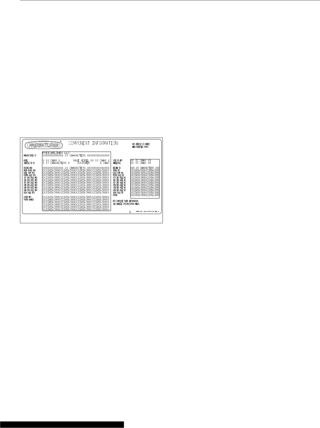
Component Information Label
NOTE: Labels shown in this chapter are ex-
amples only. Actual specifications may vary from
vehicle to vehicle.
The component information label lists the vehicle
model, identification number, and major component
models. It also lists the major assemblies and instal-
lations shown on the chassis specification sheet.
One copy of the component information label is at-
tached to the inside of the glove box; another copy is
inside the rear cover of the Owner’s Warranty Infor-
mation for North America booklet. An illustration of
the label is shown in Fig. 1.1.
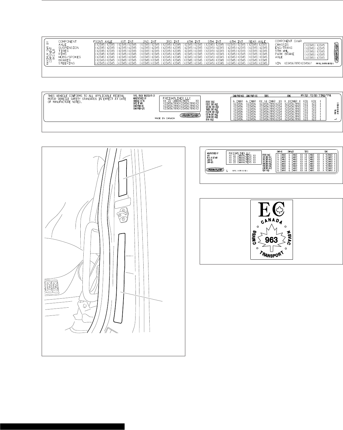
Component GWR Label
The component GWR label is located on the
passenger-side B-pillar. The label provides maximum
GWR ratings for each component.
See Fig. 1.2 for a typical component GWR label.
Federal Motor Vehicle Safety
Standard Labels
NOTE: Due to the variety of Federal Motor Ve-
hicle Safety Standard (FMVSS) certification re-
quirements, not all of the labels shown will apply
to your vehicle.
Tractors with or without fifth wheels purchased in the
U.S. are marked as certified by means of an FMVSS
certification label. See Fig. 1.3. This label is attached
to the driver-side B-pillar, as shown in Fig. 1.4.
The tire and rim portion of the FMVSS certification
label certifies suitable tire and rim combinations that
can be installed on the vehicle, for the given gross
axle weight rating. Tires and rims installed on the
vehicle at the time of manufacture may have a higher
load capacity than that certified by the tire and rim
label. If the tires and rims currently on the vehicle
have a lower load capacity than that shown on the
tire and rim label, then the tires and rims determine
the load limitations on each of the axles.
Trucks built without a cargo body that are intended
for service in the U.S. have an incomplete vehicle
certification label attached by the final-stage manu-
facturer. See Fig. 1.5. This label will be attached to
the incomplete vehicle document included with the
vehicle, and certifies that the vehicle conforms to all
applicable FMVSS regulations in effect on the date of
completion.
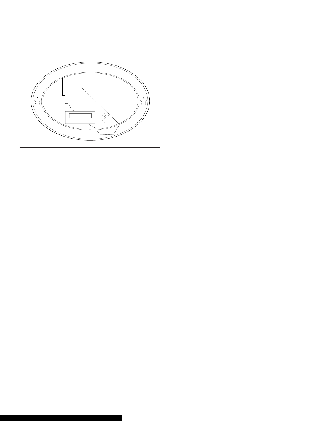
Canadian Motor Vehicle Safety
Standard Labels
In Canada, tractors with fifth wheels are marked as
certified by means of a statement of compliance label
with the Canadian National Safety Mark attached to
the driver-side door frame B-pillar. See Fig. 1.6.
Trucks built without a cargo body and tractors built
without a fifth wheel that are intended for service in
Canada have an incomplete vehicle certification label
attached to the driver-side B-pillar. After completion
of the vehicle, a complete certification label must be
attached by the final-stage manufacturer to certify
that the vehicle conforms to all applicable Canada
Motor Vehicle Safety Standard (CMVSS) regulations
in effect on the date of completion.
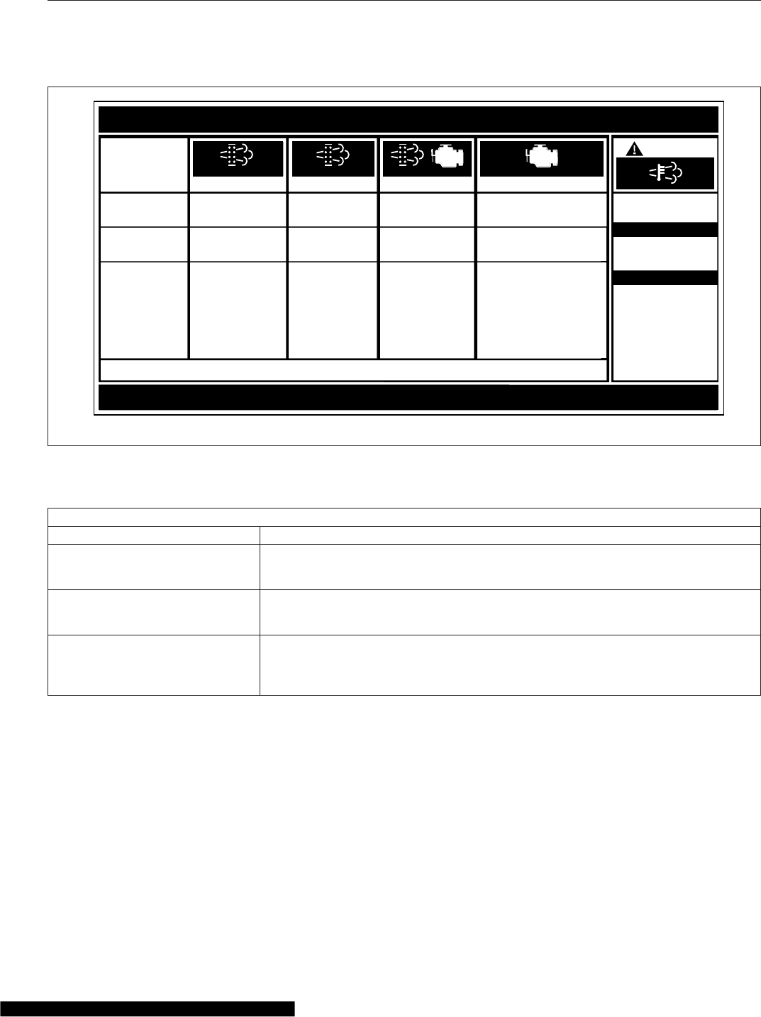
Emissions Labels
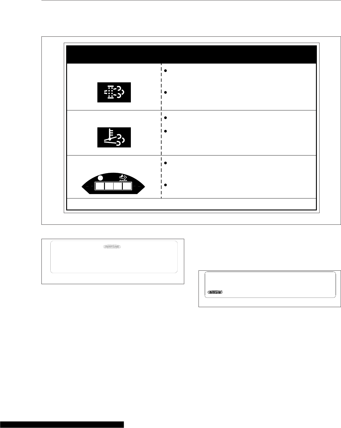
Aftertreatment System Indicators
Label
Engines and vehicles manufactured after December
31, 2006 and domiciled in the U.S. or Canada are
required to meet all EPA regulations effective as of
the vehicle build date, and are equipped with an
emission aftertreatment system (ATS). Vehicles do-
miciled outside of the U.S. and Canada may not
have aftertreatment equipment, depending upon local
statutory emissions guidelines. See Table 1.1.
02/20/2012 f080176
Fig. 1.1, Component Information Label
Vehicle Identification
1.1
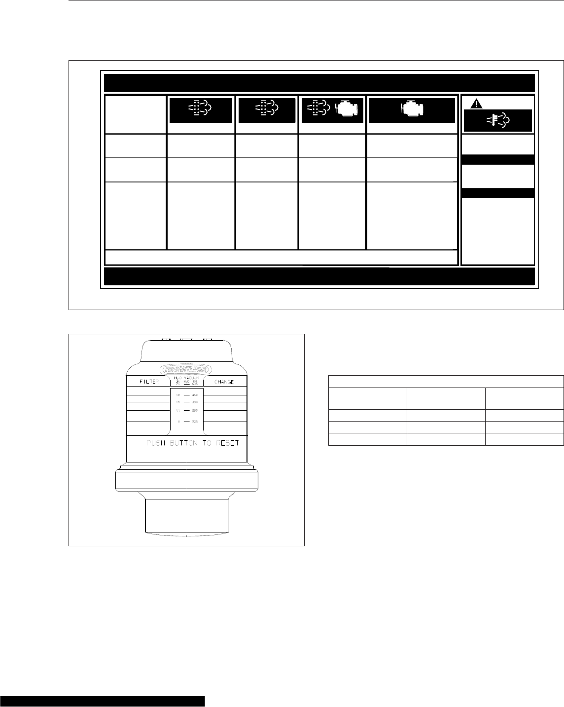
A warning label on the driver-side visor contains im-
portant warning indicators in the instrument cluster
that pertain to the ATS. See Fig. 1.7 or Fig. 1.8.
It is a violation of U.S. federal law to alter exhaust
plumbing, ATS, or other components in any way that
would bring the engine/vehicle out of compliance with
certification requirements [Ref: 42 U.S.C. S7522(a)
(3)]. It is the owner’s responsibility to maintain the
vehicle so that it conforms to EPA regulations.
02/20/2012 f080178
Fig. 1.2, Component GWR Label
02/20/2012 f080177
Fig. 1.3, Vehicle Certification Label
02/28/2012 f080182
1
2
1. EPA Noise Emission Control Label
2. FMVSS Certification Label
Fig. 1.4, Label Locations
f080180
02/28/2012
Fig. 1.5, Incomplete Vehicle Certification Label
f08002410/10/2006
Fig. 1.6, Canadian National Safety Mark
Vehicle Identification
1.2
Applicable Emissions System Based on Build Date and EPA Regulations
Build Date Regulation: Emissions Components
January 1, 2007–December 31,
2009
EPA07 (reduce nitrogen oxides (NOx) emissions to 1.1 g/bhp-hr, and reduce
particulate matter emissions to 0.01 g/bhp-hr): Aftertreatment device (ATD) containing
a diesel particulate filter that traps soot and ash.*
January 1, 2010–December 31,
2012
EPA10 (reduce NOx emissions to 0.2 g/bhp-hr): EPA07-type ATD, with additional
selective catalyst reduction (SCR) technology that utilizes diesel exhaust fluid (DEF)
to convert NOx to nitrogen and water vapor.
From March 5, 2012
GHG14: Aerodynamic and fuel efficiency components including, but not limited to,
tires, cab/sleeper side extenders, chassis fairings, bumper, hood, vehicle speed
limiters, and idle reduction timers specifically designed to meet regulatory fuel
efficiency and greenhouse gas emissions standards.
*Cummins, Detroit, and Mercedes-Benz ATD’s are also equipped with a diesel oxidation catalyst to break down pollutants.
Table 1.1, Applicable Emissions System Based on Build Date and EPA Regulations
EPA Noise Emission Control Label
A vehicle noise emission control label (Fig. 1.9)is
located on the driver-side B-pillar as shown in
Fig. 1.4. It is the owner’s responsibility to maintain
the vehicle so that it conforms to EPA regulations.
IMPORTANT: Certain Freightliner incomplete
vehicles may be produced with incomplete noise
control hardware. Such vehicles will not have a
vehicle noise emission control information label.
For such vehicles, it is the final-stage manufac-
turer’s responsibility to complete the vehicle in
conformity to U.S. EPA regulations (40 CFR Part
205) and label it for compliance.
f080156
EXHAUST AFTERTREATMENT SYSTEM INFORMATION
Switch.
Level 1 Level 3Level 2 Level 4
Filter Regeneration
Recommended.
Filter is reaching
Bring vehicle to
highway speeds to
Filter
Regeneration
Filter is now
reaching maximum
capacity
.
To avoid engine
derate, bring vehicle
Parked Regeneration
Required − Engine
Derate
Filter has reached
maximum capacity
.
Vehicle must be
parked, and a Parked
Service Regeneration Required.
Engine Derate To Idle Only.
Filter has exceeded maximum
capacity.
Vehicle must be parked, and a
Service Regeneration must be
(Solid)
(Flashing) (Flashing)
CHECK
INDICATOR
LAMP(S)
Indicator Lamp
Message(s)
Diesel Particulate
Filter Condition
Required Action
capacity
.
STOP
allow for an
Automatic
Regeneration or
perform a Parked
to highway speeds
to allow for an
Automatic
Regeneration, or
perform a Parked
Regeneration as
soon as possible.
Regeneration must
be performed.
Engine will begin
derate.
performed. Check engine
operator’s manual for details.
Engine will shut down.
For a driver performed Parked Regeneration, vehicle must be equipped with a dash mounted Regeneration Switch.
02/20/2009
W
ARNING
HEST (High Exhaust
System Temperature)
Exhaust components
and exhaust gas are at
high temperature. When
stationary, keep away
from people and
flammable materials or
vapors.
A regeneration is in
progress.
Flashing
Solid
Regeneration.
Necessary
Fig. 1.7, ATS Indicators, EPA07
Vehicle Identification
1.3
Vehicle Emission Control Information
Label
Model year 2013 and later vehicles meet additional
requirements as specified by federal greenhouse gas
and fuel efficiency regulations (GHG14). These ve-
hicles are equipped with components that increase
fuel efficiency and reduce GHG emissions. Compo-
nents may include, but are not limited to, low-rolling
resistance tires; aerodynamic devices such as hood,
cab side extenders, and fuel tank fairings; vehicle
speed limiters; and idle shutdown timers.
A Vehicle Emission Control Information Label is lo-
cated on the driver-side door. See Fig. 1.10.Itisthe
owner’s responsibility to maintain the vehicle so that
it conforms to EPA and NHTSA regulations.
Certified Clean Idle Label
The California Air Resources Board (CARB) requires
model year 2008 and newer heavy-duty diesel en-
gines to be equipped with a non-programmable en-
gine shutdown system that automatically shuts down
the engine after five minutes of idling in order to limit
emissions of particulate matter and NOx.
DPF Regen Needed
Hot Exhaust
DEF Refill Needed
Diesel Particulate Filter (DPF)
regeneration is needed.
If flashing, regenerate as soon as
possible. Engine derate possible.
Hot exhaust can cause fire.
Keep flammables and people away
from exhaust.
Diesel Exhaust Fluid (DEF) level is
low. Engine derate likely.
Refill tank with certified DEF.
24−01656−000
IMPORTANT
DEF
11/30/2010 f080162
See operator’s manual for complete instructions.
Fig. 1.8, ATS Indicators, EPA10 and Newer
10/06/98 f080026
24−00273−020
VEHICLE NOISE EMISSION CONTROL INFORMATION
FREIGHTLINER CORPORATION
THIS VEHICLE CONFORMS TO U.S. EPA REGULATIONS FOR NOISE EMISSION
APPLICABLE TO MEDIUM AND HEAVY TRUCKS.
THE FOLLOWING ACTS OR THE CAUSING THEREOF BY ANY PERSON ARE PROHIBITED BY
THE NOISE CONTROL ACT OF 1972:
A. THE REMOVAL OR RENDERING INOPERATIVE, OTHER THAN FOR PURPOSES OF
MAINTENANCE, REPAIR, OR REPLACEMENT, OF ANY NOISE CONTROL DEVICE OR
ELEMENT OF DESIGN (LISTED IN THE OWNER’S MANUAL) INCORPORATED INTO THIS
VEHICLE IN COMPLIANCE WITH THE NOISE CONTROL ACT.
B. THE USE THIS VEHICLE AFTER SUCH DEVICE OR ELEMENT OF DESIGN HAS
BEEN REMOVED OR RENDERED INOPERATIVE.
DATE OF MANUFACTURE
01/96
Fig. 1.9, Vehicle Noise Emission Control Label
f080181
02/29/2012
MANUFACTURED BY:
VIN:
VEH FAMILY CD:
GVWR−KG
GVWR−LBS
REGULATORY CLASS:
EMISSION CONTROL IDENTIFIERS:
DATE OF MANUFACTURE:
VEHICLE EMISSION CONTROL INFORMATION
THIS VEHICLE COMPLIES WITH U. S. EPA REGULATIONS FOR XXXX HEAVY DUTY VEHICLES.
SEE OWNER’S MANUAL FOR PROPER MAINTENANCE OF THIS VEHICLE. U PART NO. 24−01177−060 REV A
Fig. 1.10, Vehicle Emission Control Information Label
Vehicle Identification
1.4
Certified vehicles are equipped with a label placed
near the bottom edge of the driver-side door. See
Fig. 1.11.
CERTIFIED
CLEAN IDLE
02/20/2012 f080179
Fig. 1.11, CARB Clean Idle Label
Vehicle Identification
1.5

2
Vehicle Access
Cab Door Locks and Handles ....................................................... 2.1
Grab Handles and Access Steps ..................................................... 2.1
Cab-to-Sleeper Access ............................................................. 2.3
Sleeper Door ..................................................................... 2.3
Sleeper Luggage Door ............................................................. 2.4
Back-of-Cab Access ............................................................... 2.4
Hood Opening and Closing ......................................................... 2.5
Cab Door Locks and Handles
One common key operates the ignition switch and all
of the door locks.
IMPORTANT: Each key is numbered. Record
the number so a duplicate key can be made, if
needed.
To unlock the driver’s door from outside the cab, in-
sert the key in the lockset and turn it one-quarter turn
clockwise. See Fig. 2.1. To remove the key, turn it
counterclockwise to the original position. Pull out on
the door pull handle to open the door.
To unlock the passenger’s door from outside the cab,
insert the key in the lockset and turn it one-quarter
turn counterclockwise. Turn the key clockwise to the
original position to remove it.
NOTE: The cab door locks can be operated
when the doors are open.
To lock a door from outside the cab, insert the key in
the lockset and turn it in the direction opposite to the
unlocking direction (counterclockwise for the driver’s
door, clockwise for the passenger’s door). Close the
door if it is open.
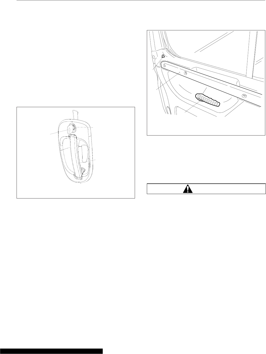
To lock either door from inside the cab, push the lock
button downwards. See Fig. 2.2.
To open the door from the inside, lift up on the door
lever. This will unlatch the door whether or not it is
locked.
To unlock the door without unlatching it, pull the lock
button upwards.
Grab Handles and Access
Steps
WARNING
Wet or dirty shoe soles greatly increase the
chance of slipping or falling. If your soles are wet
or dirty, be especially careful when climbing
onto, or down from, the back-of-cab area.
Always maintain three-point contact with the
back-of-cab access supports while entering and
exiting the back-of-cab area. Three-point contact
means both feet and one hand, or both hands
and one foot, on the grab handles, steps, and
deck plates. Other areas are not meant to sup-
port back-of-cab access, and grabbing or step-
ping in the wrong place could lead to a fall, and
personal injury.
Be careful not to get hands or feet tangled in
hoses or other back-of-cab equipment. Careless-
ness could cause a person to trip and fall, with
possible injury.
10/22/2001 f720397
1
2
3
1. Key
2. Lockset
3. Door Pull Handle
Fig. 2.1, Exterior Door Handle
06/22/2006
1
2
3f720639
1. Lock Button
2. Integral Door Upper Grab Handle
3. Door Lever
Fig. 2.2, Door Interior
Vehicle Access
2.1
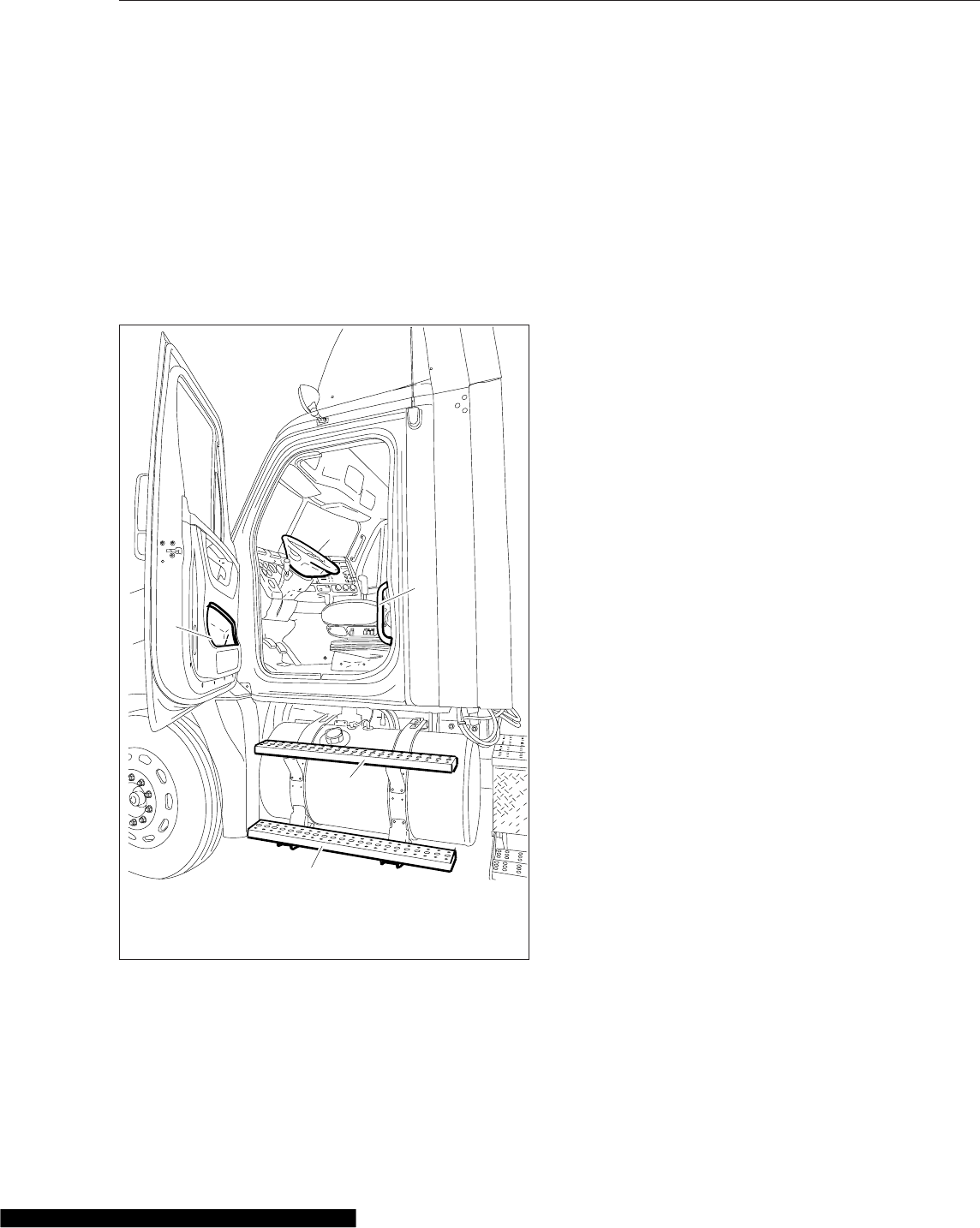
Entering the Driver Side
When entering the cab from the driver side, use the
grab handle and access steps as follows:
1. Open the driver side door, and place anything
that you are carrying in the cab.
2. Using both hands, grasp the grab handle that is
on the B-pillar, or use your left hand on the inte-
gral door lower grab handle. See Fig. 2.3. Reach
up as far as is comfortable.
3. Place your right foot on the bottom step, and pull
yourself up. Move your left hand to the integral
door upper grab handle.
4. Place your left foot on the top step.
5. Grasp the steering wheel with your left hand, and
step up.
6. Step into the cab with your right foot first, and
grasp the steering wheel with your right hand.
Exiting the Driver Side
Exit the cab from the driver side as follows:
IMPORTANT: Do not attempt to exit the cab
while carrying any items in your hands.
1. Grasp the steering wheel with both hands, place
your left foot on the top step, then stand on the
threshold facing into the cab.
2. Using your right hand, grasp the grab handle,
located on the B-pillar.
3. Move your right foot to the bottom step.
4. Move your left hand to the integral door lower
grab handle.
5. Step to the ground with your left foot first.
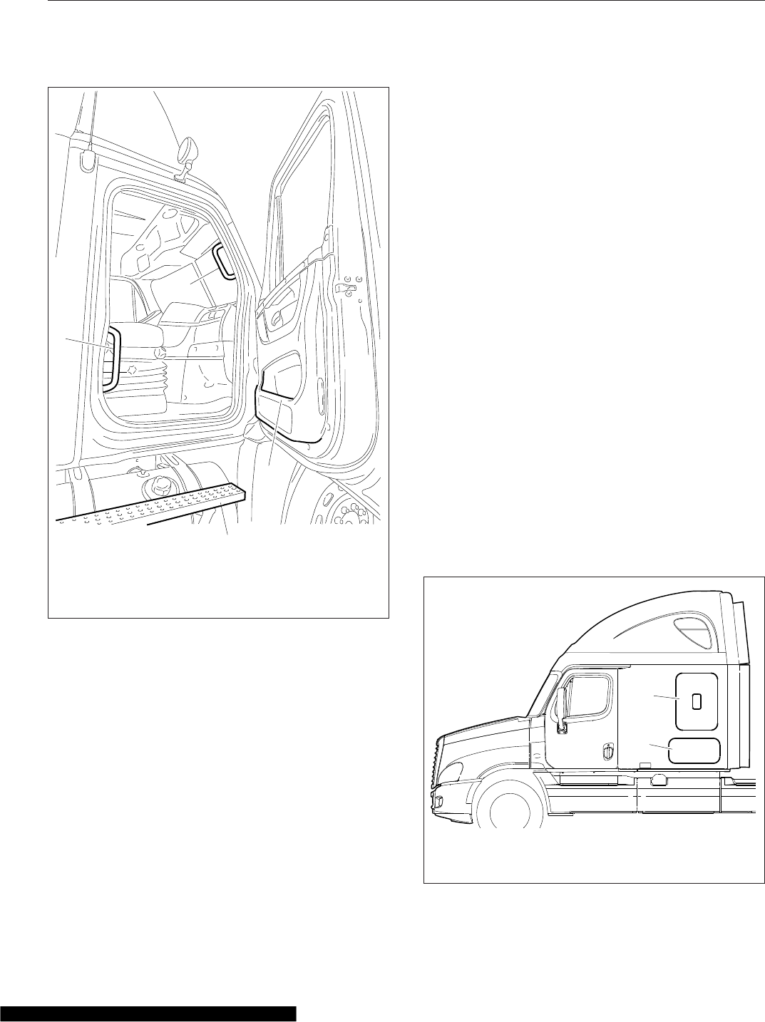
Entering the Passenger Side
When entering the cab from the passenger side, use
the grab handles and access steps as follows:
1. Open the passenger-side door, and place any-
thing that you are carrying in the cab.
2. Using your left hand, grasp the grab handle
that’s on the rear of the door opening. See
Fig. 2.4.
3. Using your right hand, grasp the integral door
lower grab handle.
4. Place your right foot on the bottom step, and
step up to the upper step with your left foot.
5. Place your right foot on the top step, and step
up.
6. Move your right hand to the upper grab handle
on the windshield post.
7. Step into the cab with your left foot first.
Exiting the Passenger Side
Exit the cab from the passenger side as follows:
IMPORTANT: Do not attempt to exit the cab
while carrying any items in your hands.
11/30/2006 f602271
1
2
3
4
5
1. Steering Wheel
2. B-Pillar Grab Handle
3. Bottom Step
4. Top Step
5. Integral Door Lower
Grab Handle
Fig. 2.3, Driver-Side Steps and Grab Handle
Vehicle Access
2.2
1. Using both hands, grasp the grab handle thats
on the windshield post, and place your right foot
on the top step while standing up from the seat
facing inward.
2. Place your left foot on the bottom step.
3. Move your left hand to the lower grab handle
located at the rear edge of the door opening.
See Fig. 2.4.
4. Move your right hand to the integral door lower
grab handle.
5. Step to the ground with your right foot first.
Cab-to-Sleeper Access
To open the sleeper access on vehicles with vinyl
sleeper curtains, unzip the sleeper curtains. If de-
sired, unsnap the curtains all the way around the
sides and top, and remove the curtains.
To open the sleeper access on vehicles with velour
sleeper curtains, unfasten the snaps at one side,
then push the curtain to the opposite side.
Sleeper Door
The sleeper door (Fig. 2.5, Ref. 1) is not intended for
entry or exit. The door is intended only as a conve-
nient means to stow or remove personal belongings
in and from the sleeper area. To open the sleeper
door from the inside, push down on the lever handle
located inside the sleeper compartment aft of the
door, or pull out on the upper lever located inside the
cab door opening; see Fig. 2.6. To open the sleeper
door from outside, open the cab door, then pull out
on the upper lever located inside the cab door open-
ing. To close the door, pull on the strap attached to
the inside of the door, or push it closed from the out-
side, until it latches.
IMPORTANT: The sleeper doors are two-stage
latching. When closing the doors, ensure that
they are completely latched to prevent wind
noise and water intrusion.
01/03/2007 f720643
1
2
3
4
1. Lower Grab Handle
2. Upper Grab Handle
3. Integral Door Lower Grab Handle
4. Top Step
Fig. 2.4, Passenger-Side Steps and Grab Handles
04/20/2007
1
2
f602302
1. Sleeper Door
2. Luggage Compartment Door
Fig. 2.5, Sleeper Doors
Vehicle Access
2.3
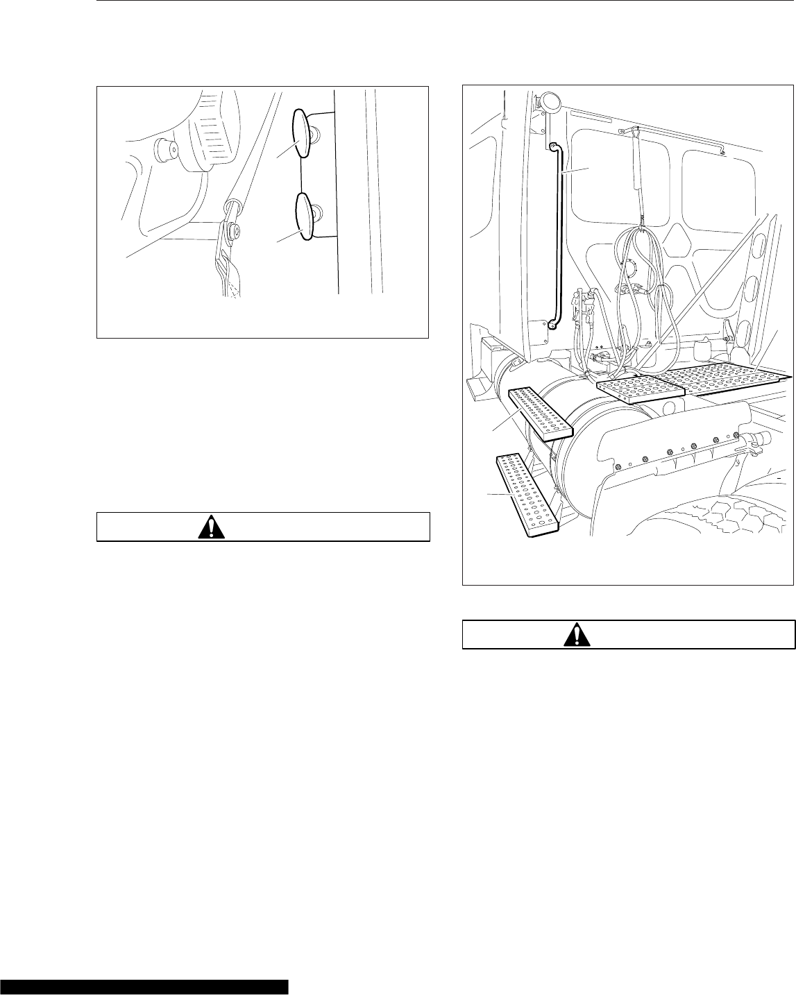
Sleeper Luggage Door
To open the sleeper luggage door, pull out on the
lower lever located inside the cab door opening. See
Fig. 2.6. To close the door, push it closed until it
latches.
Back-of-Cab Access
WARNING
External surfaces of the exhaust system remain
hot after the engine has been shut down. When
accessing the back of the cab or sleeper, do not
touch any part of the exhaust system, or severe
burns could occur.
When trailer air and electrical connections cannot be
reached conveniently from the ground, Federal Motor
Carrier Safety Regulations require commercial carri-
ers to provide back-of-cab access.
Optional grab handles are mounted either on both
cab sidewalls, or on the left sidewall only. See
Fig. 2.7. Steps are mounted either on the fuel tank(s)
or on metal brackets. When a deck plate is neces-
sary, it is mounted across the top of the frame rails.
IMPORTANT: Climb onto, and down from, back-
of-cab access facing in toward the vehicle, as
you would on a ladder. Do not climb up or down
facing out away from the vehicle.
WARNING
Wet or dirty shoe soles greatly increase the
chance of slipping or falling. If your soles are wet
or dirty, be especially careful when climbing
onto, or leaving, the back-of-cab area.
Always maintain three-point contact with the
back-of-cab access supports while entering and
exiting the back-of-cab area. Three-point contact
means both feet and one hand, or both hands
and one foot, on the grab handles, steps, and
deck plates. Other areas are not meant to sup-
port back-of-cab access, and grabbing or step-
ping in the wrong place could lead to a fall, and
personal injury.
03/22/2007 f720661
1
2
1. Sleeper Door Lever
2. Luggage Door Lever
Fig. 2.6, Sleeper Door Levers
09/24/2007 f602335
2
1
1
3
1. Steps
2. Grab Handle
3. Deck Plate
Fig. 2.7, Back-of-Cab Access
Vehicle Access
2.4
Be careful not to get hands or feet tangled in
hoses or other back-of-cab equipment. Careless-
ness could cause a person to trip and fall, with
possible injury.
Entering Back-of-Cab
When climbing onto the deck plate, do the following:
1. Grasp the sidewall grab handle with both hands.
Reach up as far as is comfortable.
2. Place one foot on the bottom step and pull your-
self up.
3. Place your other foot on the top step.
4. Move your lower hand to a higher position on the
grab handle.
5. Step onto the deck plate.
Climbing Down from Back-of-Cab
To climb down from the back-of-cab area:
1. Grasp the sidewall grab handle with both hands.
2. Step one foot at a time onto the top step.
3. Move your upper hand to a lower position on the
grab handle.
4. Move one foot to the bottom step.
5. Move your upper hand to a lower position on the
grab handle.
6. Step to the ground with your upper foot first.
Hood Opening and Closing
A grab handle at the front of the hood provides a
hand-hold for hood tilting. Two tilt-assist struts help to
tilt the hood open, and to return it to the operating
position. A damper controls the closing rate of the
hood and hood straps prevent the hood from over-
travel. In the operating position, the hood is secured
by a hold-down latch on each side of the hood.
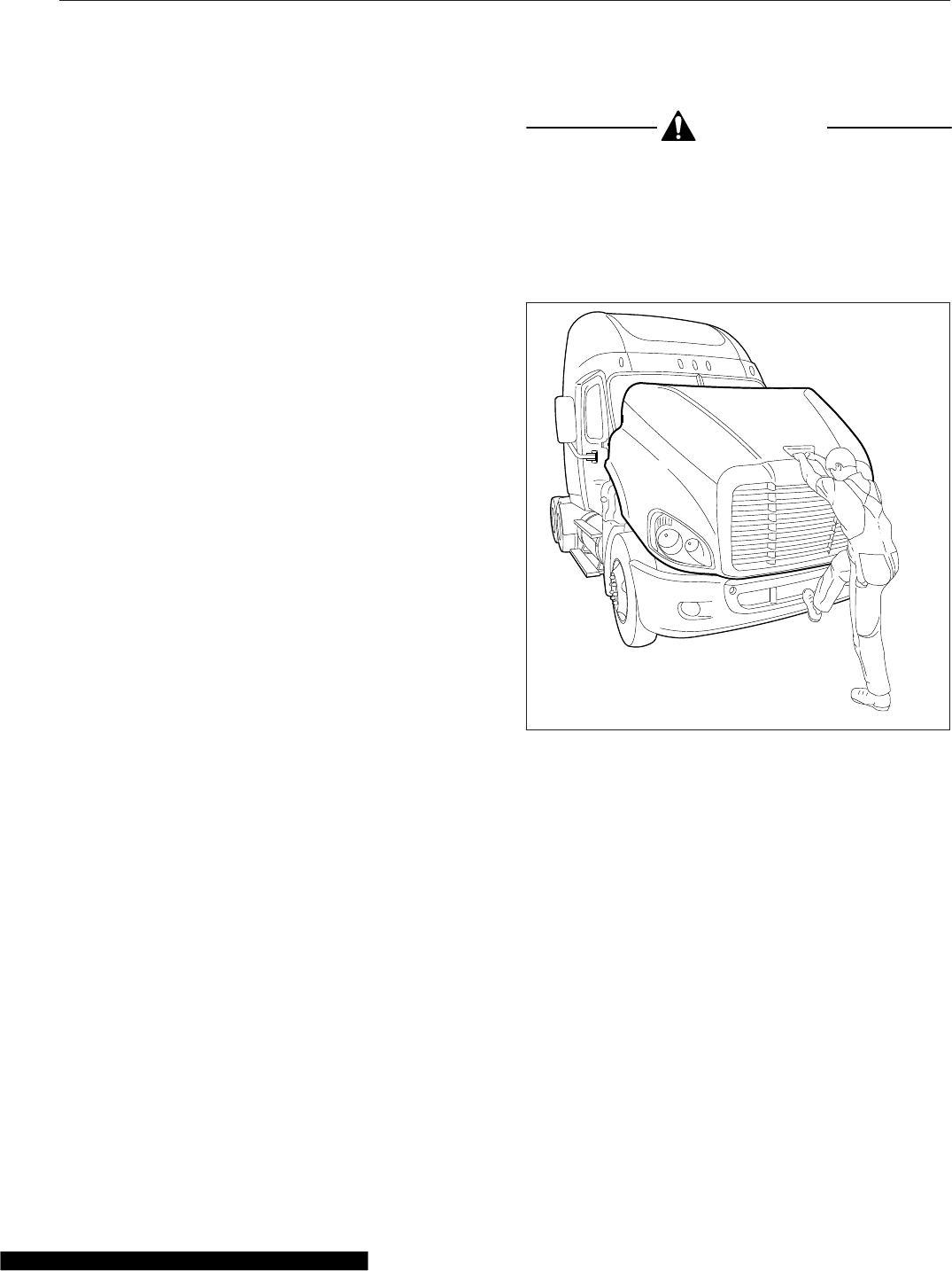
To Tilt the Hood
1. Apply the parking brakes.
2. Release both hood hold-down latches by pulling
the ends outward.
CAUTION
Do not let the hood free-fall to the full-open posi-
tion. To do so could cause damage to the hood
or hood straps.
3. Using the bumper step and grab handle, slowly
tilt the hood until the straps support it. See
Fig. 2.8.
To Return the Hood
1. Grasp the grab handle, and lift the hood a just-
over-center position.
2. As the hood goes over center, the hood damper
controls the rate of descent to the operating posi-
tion.
3. Make sure the hood is flush with the cowl, then
secure the hood by engaging both hood hold-
down latches.
IMPORTANT: Make sure that both hold-down
latches are fully engaged before operating the
vehicle.
03/22/2007 f880788
Fig. 2.8, Hood Tilting
Vehicle Access
2.5

3
Electrical System
Electrical Power Distribution ........................................................ 3.1
Emergency Power Supply .......................................................... 3.3
Progressive Low Voltage Disconnect ................................................. 3.4

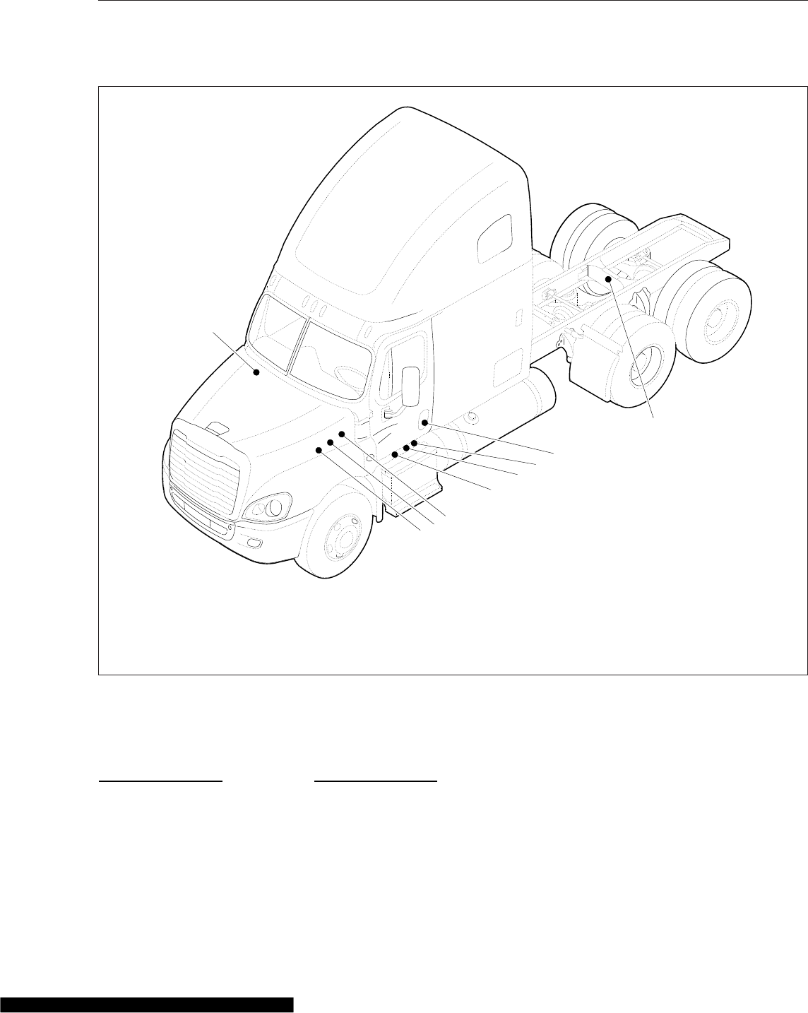
Electrical Power Distribution
Electrical power distribution provides battery power to
the electrical and electronic systems. See Fig. 3.1 for
power distribution component locations.
The following components make up the power distri-
bution system:
•MEGA Fuse Junction Block (MFJB), EPA07
only
•Powertrain Power Distribution Module
(PT-PDM)
•Powernet Distribution Box (PNDB), EPA10 and
newer
•Cab Load Disconnect Switch
•Auxiliary PDM
MEGA Fuse Junction Block, EPA07
On EPA07 vehicles, the MFJB distributes battery
power to the alternator, SAM cab, SAM chassis, and
powertrain PDM. Battery power may also be routed
to an inverter and a trailer PDM. The MFJB houses
up to five MEGA fuses, and is located on the left
frame rail in front of the batteries. See Fig. 3.2.
Powernet Distribution Box, EPA10
and Newer
The PNDB distributes battery power to the SAM cab,
SAM chassis, powertrain PDM, and other keep-alive
circuits.
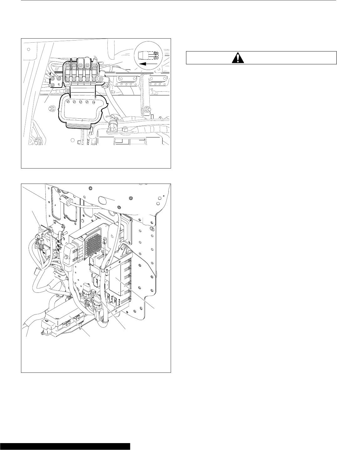
The PNDB is mounted in the engine compartment on
the frontwall near the steering column. The label on
the PNDB fuse cover identifies typical circuits. See
Fig. 3.3.
Power Distribution Modules
Powertrain PDM
The powertrain PDM contains fuses and relays that
provide battery and ignition power to the engine, af-
tertreatment device, transmission, and other
powertrain-related circuits. It is mounted in the en-
gine compartment, above the driver-side inner
fender.
Auxiliary PDM
The optional auxiliary PDM is used when additional
circuit protection is needed for optional features. For
example, if a beacon light is added to the Cascadia,
it may require an auxiliary PDM. The auxiliary PDM
may contain fuses and relays for these devices. It is
mounted in the cab, behind the doghouse cover.
Trailer PDM
The optional trailer PDM, mounted on the frame rail,
is used to supply trailer power to the chassis-
mounted trailer receptacles. The SAM chassis sup-
plies control signals to the relays in the trailer PDM.
SAM Cab
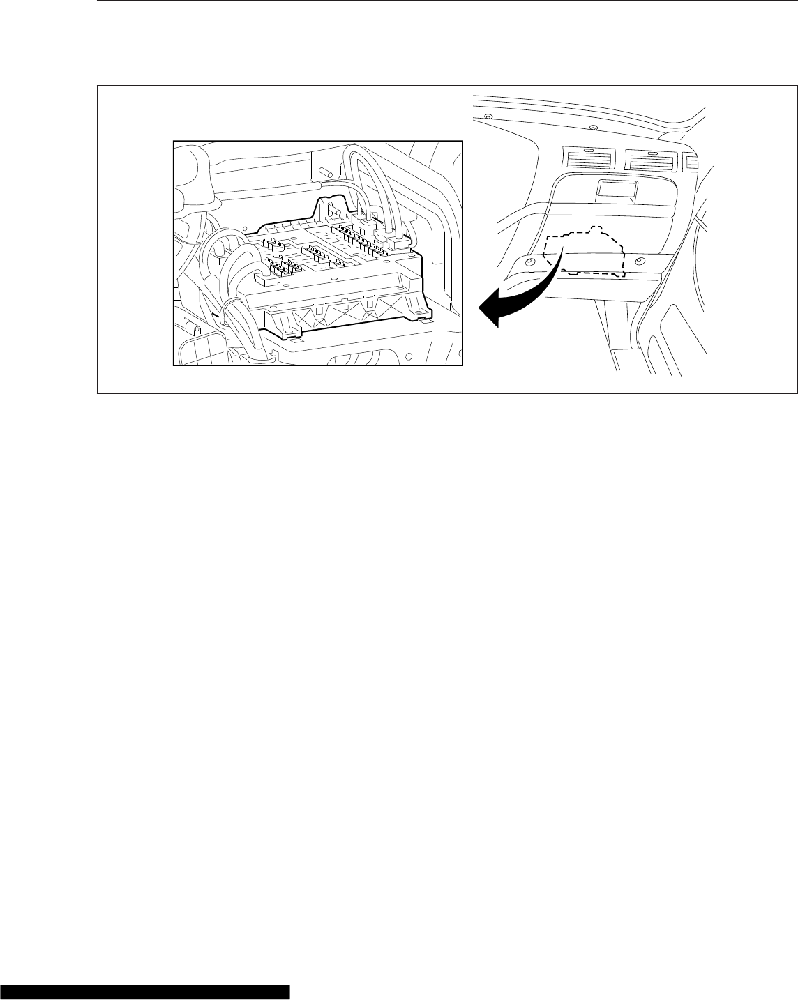
The SAM cab is located behind the glove box inside
the vehicle cab. See Fig. 3.4. The SAM cab contains
fuses and relays in addition to solid state circuit pro-
tection devices that will trip when a circuit is over-
loaded.
Refer to Chapter 25 for fuse and relay locations.
SAM Chassis
The SAM Chassis is located in the engine compart-
ment on the driver-side frontwall. See Fig. 3.3. The
SAM chassis contains fuses and relays in addition to
solid state circuit protection devices that will trip
when a circuit is overloaded.
Refer to Chapter 25 for fuse and relay locations.
Circuit Protection Features
The SAM chassis and SAM cab may be equipped
with self-resetting circuit breakers instead of fuses.
Self-resetting circuit breakers are tripped when they
reach 170°F (77°C), then self-reset once the tem-
perature drops sufficiently. When the circuit overload
is removed, this circuit protection will self-reset.
Some of these circuits require the ignition switch to
be cycled off then back on again for the self-reset to
occur.
Some ECU’s are equipped with a self-resetting circuit
breaker removal tool.
WARNING
Always wear heat-protective gloves when han-
dling a self-resetting circuit breakers, which can
Electrical System
3.1
reach extremely high temperatures. Failure to use
appropriate heat protection can lead to serious
injury.
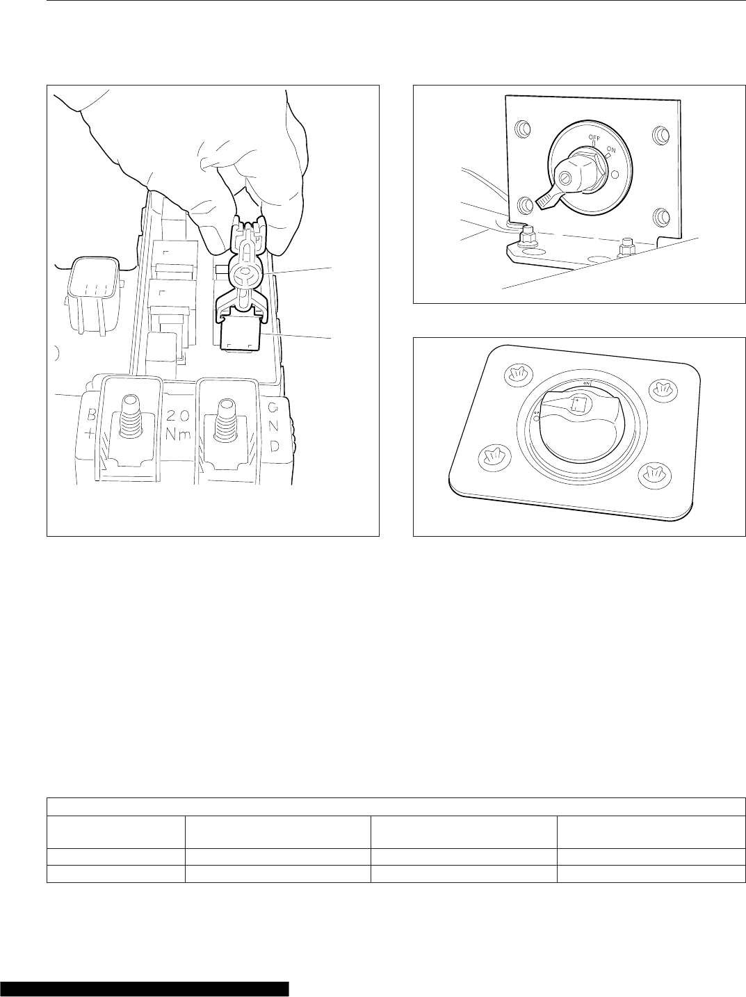
NOTICE
Self-resetting circuit breakers can be perma-
nently damaged if improperly handled. Use the
guidelines below to handle them safely.
•Disconnect the batteries before removing a
self-resetting circuit breaker.
•Use a circuit breaker removal tool to remove a
self-resetting circuit breaker. See Fig. 3.5. Use
of any other tool, including pliers, may damage
the circuit breaker.
•Never attempt to probe a self-resetting circuit
breaker while installed on the SAM Cab or
SAM Chassis. Remove the circuit breaker first,
or use a non-contact infrared thermometer to
measure temperature.
f001175a
02/27/2012
2
1
4
9
8
6
5
3
7
1. SAM Cab
2. Powertrain PDM (PT-PDM)
3. Powernet Distribution Box (PNDB)
4. SAM Chassis
5. Main Ground Junction Block
6. MEGA Fuse Junction Block
7. Cab Load Disconnect Switch (optional location)
8. Cab Load Disconnect Switch (optional location)
9. Trailer PDM
Fig. 3.1, Component Locations
Electrical System
3.2
Cab Load Disconnect Switch
WARNING
Turning the cab load disconnect switch (CLDS) to
the off position does not disconnect the connec-
tion between the battery and the starter. To work
on the vehicle safely, the negative leads must be
disconnected from the battery.
IMPORTANT: The ignition should be turned off
before turning the CLDS to on or off.
The CLDS is used to avoid excessive draw on the
battery when the vehicle is parked for an extended
period of time by disconnecting (or opening) the con-
nection between the battery and the most of the ve-
hicle electrical system.
The CLDS may be mounted:
•inside the cab on the outboard side of the
driver’s seat;
•at the battery box;
•outboard on the left frame rail.
See Fig. 3.6 for an EPA07 CLDS; see Fig. 3.7 for an
EPA10 and newer switch.
If the CLDS is turned to the off position while the ve-
hicle is running, the emergency power system will
activate. The powertrain PDM will receive power from
the emergency power feed, but the batteries will not
be charging. See the Emergency Power Supply
heading below for details.
Emergency Power Supply
The Cascadia electrical system has an emergency
power circuit that supplies battery power for exterior
lighting. This assists vehicle visibility in the event a
MEGA fuse is open circuit. The emergency power
circuit is live even when the CLDS is turned off.
The emergency power supply feature allows for the
vehicle to be driven off the highway and for the exte-
rior lighting to remain on in the event of a SAM Cab
or SAM Chassis failure. The emergency power sup-
ply will cause certain exterior lamps to flash (depend-
ing on if it is the SAM Cab or SAM Chassis that
failed), indicating that the vehicle is disabled.
06/15/2007 f545073
1
2
1. MEGA Fuse Junction Block
2. Main Ground Junction Block
Fig. 3.2, EPA07 MEGA Fuse Junction Block
02/27/2012 f545682a
1
3
2
4
1. Powertrain PDM (PT-PDM)
2. Inline Fuse, Auxiliary PDM
3. SAM Chassis
4. Powernet Distribution Box (PNDB)
Fig. 3.3, Engine Compartment Power Distribution
Components
Electrical System
3.3
SAM Cab Fault
If the emergency power supply system activates, do
not shut down the engine until the vehicle is in a safe
position to do so. It will not be able to be restarted
until the problem is corrected. If emergency power
mode is due to a SAM Cab fault, the gauges will be-
come unresponsive but the engine will remain run-
ning until it is turned off.
When the ignition is in the ON position, the emer-
gency power supply will cause the following lamps to
flash:
•dash panel lights
•clearance lights
•front marker lights
•side marker lights
•trailer taillights
•rear stop lights
SAM Chassis Fault
The engine may be able to be restarted when the
SAM Chassis fails. When the ignition is in the ON
position, the emergency power supply will cause the
following lamps to flash:
•dash panel lights
•identification lights
•front marker lights
•turn-signal indicators in the ICU (alternately)
•side marker lights
•rear turn-signal lights
•trailer taillights
If the ignition switch is turned ON while the load dis-
connect switch is in the OFF position, the emergency
power supply feature will activate the following
lamps:
•clearance lights (flashing)
•side marker lamps (flashing)
•low beam headlights
Progressive Low Voltage
Disconnect
The progressive low voltage disconnect (PLVD) fea-
ture protects the batteries from excessive discharge
by disconnecting certain circuits from battery power
supply. This allows the batteries to maintain accept-
able charge to restart the vehicle.
When battery voltage drops below a predetermined
value, loads designated as comfort loads (priority
f544945
02/07/2007
Fig. 3.4, SAM Cab Location
Electrical System
3.4
level I) are shut down first. Then loads designated as
house loads (priority level II) are shut down. If neces-
sary, basic loads (priority level III) are shut down last.
PLVD allows the driver to continue using critical
loads, while noncritical loads are temporarily unavail-
able. Calculations for disconnecting loads are based
on battery voltage, ignition switch status, and engine
rpm. Also, a time delay is implemented for the shut-
down and reactivation of loads to avoid unnecessary
cycling of loads when battery voltage is close to
shutdown thresholds.
One minute before the comfort loads or house loads
are shut down, the alarm in the instrument cluster
beeps. No alarm sounds before basic loads are shut
down.
If the interior lights have been shut down by PLVD,
pressing one of the interior light switches (if
equipped) brings the interior lights back on.
See Table 3.1 for the type of loads shut down under
specific conditions.
See Table 3.2 for the loads that are designated com-
fort, house, and basic load status.
Type of Loads Shut Down Under Specific Conditions
Key Switch Position Engine On, Voltage less than
12.5 Volts
Engine Off, Voltage less than
12.3 Volts
Engine Off, Voltage less than
12.1 Volts
Off N/A Priority level I, II loads Priority level I, II, and III loads
Accessory N/A Priority Level I loads Priority level I, II loads
02/20/2012 f545876
1
2
1. Circuit Breaker
Removal Tool
2. Self-Resetting Circuit
Breaker
Fig. 3.5, Self-Resetting Circuit Breaker Removal
06/19/2007 f545071
Fig. 3.6, Cab Load Disconnect Switch, EPA07
05/13/2009 f545527
Fig. 3.7, Cab Load Disconnect Switch, EPA10 and
Newer
Electrical System
3.5

Type of Loads Shut Down Under Specific Conditions
Key Switch Position Engine On, Voltage less than
12.5 Volts
Engine Off, Voltage less than
12.3 Volts
Engine Off, Voltage less than
12.1 Volts
On Priority level I loads Priority Level I loads Priority level I, II loads
Start N/A N/A N/A
Table 3.1, Type of Loads Shut Down Under Specific Conditions
Designated Loads
Type of Load Function
Priority Level I
12V power receptacle 6 (sleeper, refrigerator)
Amplifier power, accessory
General sleeper light
Foot well light
Reading light 1 (dimmer/theater)
Reading light 2 (dimmer/theater)
Rear baggage compartment light
12V power receptacle 5 (sleeper, cigar), battery
Auxiliary circulation fan-sleeper, battery
12V power receptacle 4 (sleeper, cigar), battery
Reading light 4 (switched locally), battery
Priority Level II
Heated seats, ignition*
Sleeper HVAC controller, accessory*
Cabin HVAC controller, accessory*
Radio, accessory (clamp 15R)
Power feed spare output I, battery
Power feed spare output III, battery
Mirror heating, passenger*
Mirror heating, driver*
Power feed spare output IV, battery
Power feed spare output II, battery
Fuel/water separator heater element, ignition*
Air dryer (pneumatic, electrically heated), accessory*
Auxiliary circulation fan-windshield, accessory*
Accessory heater power
Utility light
Utility light
Dome light rear
Area lighting (lower bunk and sleeper work surface),
battery
Dome light cab, battery
Overhead compartment lights, battery
12V power receptacle 3 (sleeper, cigar), battery
Stand-alone HVAC, battery
Advertising light, accessory*
Dome light passenger
Dome light driver/forward overhead
Electrical System
3.6

Designated Loads
Type of Load Function
Priority Level III
CB radio, battery†
Fleet management system, battery†
Trailer power, battery or ignition
12V power receptacle 2 (dash, phone), battery
12V power receptacle 1 (dash, cigar), battery
*When the vehicle has Optimized Idle, these functions will not operate with the ignition switch in the accessory
position. Optimized Idle may also turn these functions off to reduce stress on the batteries. Refer to the Opti-
mized Idle section in Chapter 11 for more information.
†May or may not shut down depending on how an additional parameter is set at the factory or dealership.
Table 3.2, Load Designation
Electrical System
3.7

4
Instruments
Instrumentation Control Units ....................................................... 4.1
Warning and Indicator Lights ........................................................ 4.3
Instruments ...................................................................... 4.7
Driver Message Center ........................................................... 4.11
Overhead Instrument Panel ........................................................ 4.24
Instrumentation Control Units
The instrumentation control unit (ICU) provides the
driver with engine and vehicle information. It is com-
prised of standard and optional gauges, an audible
warning, a driver message center, and a lightbar con-
taining warning and indicator lamps (also known as
telltales). Warning and indicator lamps illuminate in
red (danger), amber (caution), green (status advi-
sory), or blue (high-beam headlights active).
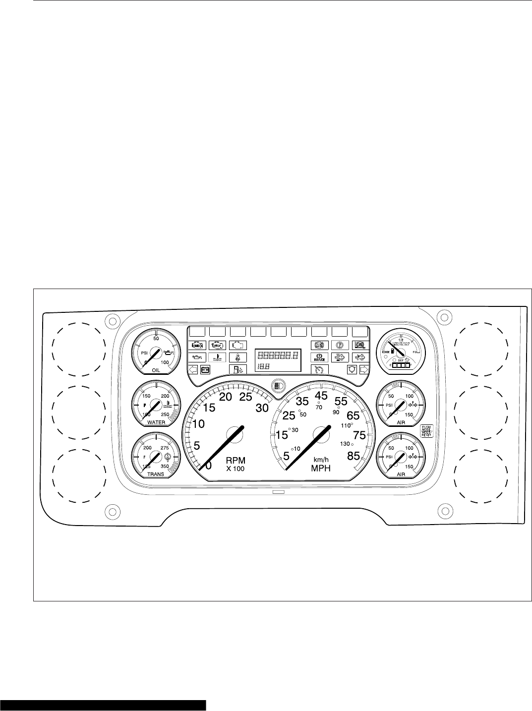
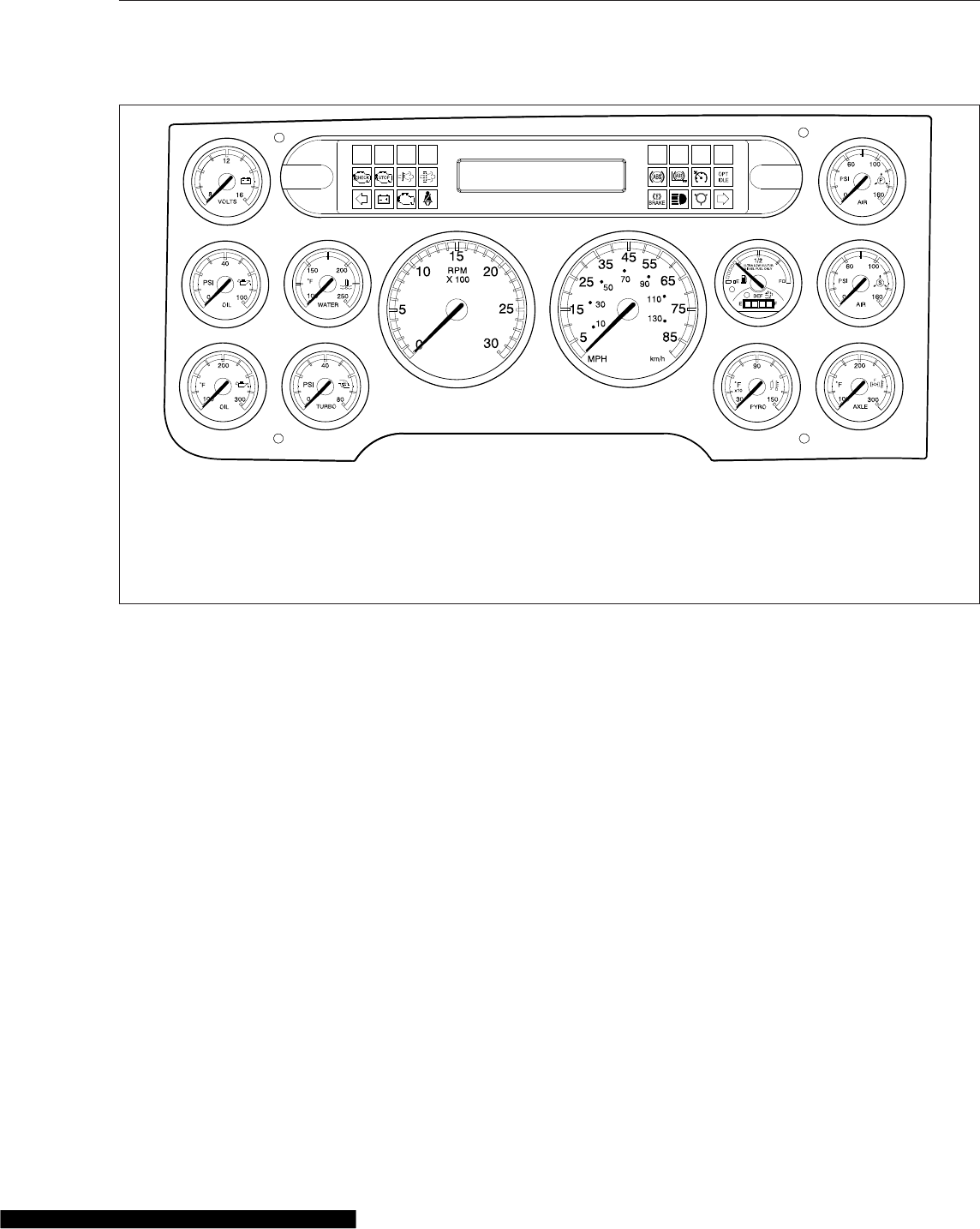
Cascadia vehicles are equipped with an ICU3, ICU4,
ICU4M, or ICU4Me. See Fig. 4.1,Fig. 4.2, and
Fig. 4.3 for typical ICU layouts.
The following headings in this chapter provide addi-
tional information and operating instructions for ICU
components:
•"Warning and Indicator Lights"
•"Instruments"
•"Driver Message Center"
Ignition Sequence
When the ignition is turned on, the ICU runs a self-
check. See Fig. 4.4. Observing the ignition sequence
is a good way to ensure the ICU is functioning prop-
erly.
IMPORTANT: Do not crank the engine until the
ICU self-check is complete.
NOTE: Air gauges do not complete a sweep of
their dials during the ignition sequence.
When the ignition is turned on, the following actions
should occur:
•electronic gauges complete a full sweep of
their dials
09/10/2009 f610864a
1
2
3
4
5
6
7
8
9
13
10
11
12
1. Transmission Temperature Gauge
2. Coolant Temperature Gauge
3. Engine Oil Pressure Gauge
4. Driver Message Center
5. Fuel/DEF Level Gauge
6. Primary Air Pressure Gauge
7. Secondary Air Pressure Gauge
8. Speedometer
9. Tachometer
10. High Beam Indicator
11. Driver Display Screen
12. Mode/Reset Switch
13. Satellite Gauges
Fig. 4.1, ICU3 Instrument Cluster (EPA10 shown)
Instruments
4.1
•warning and indicator lamps illuminate, then
are extinguished
•audible alert sounds for approximately four
seconds or until sufficient air pressure builds
up in the primary and secondary air systems
•DEF level indicator illuminates all segments
green, then turns them off one at a time before
turning the leftmost segment amber and then
red
•Freightliner logo displays on the ICU4Me driver
message center for two seconds.
•software revision level of the ICU is displayed
on the driver message center, followed by any
active faults
IMPORTANT: If any red or amber warning and
indicator lamps do not illuminate during the ICU
self-check or do not go out after the self-check
completes, take the action outlined in Table 4.1,
or take the vehicle to an authorized Freightliner
service facility as soon as possible.
NOTE: If active faults are present, take the ve-
hicle to an authorized Freightliner service facility
as soon as possible.
If the ICU receives active fault codes, it displays
them one after the other until the parking brake is
released or the ignition is turned off. Once the park-
ing brake is completely released, the ICU displays
the odometer. If there are no active faults, the ICU
displays the odometer after the self-check completes.
When the self-check is complete on an ICU4M, the
fasten seat belt screen displays if the engine is off. If
the engine is running, the idle hours screen displays.
Audible Alerts
An audible alert sounds during the ignition sequence
and whenever one of the following conditions exists:
•Engine oil pressure falls below the minimum
preset value.
•Coolant temperature rises above the maximum
preset value.
f610865b
1
34
56
7
89
10
11 12
13 14
2
09/10/2009
NOTE: The ICU4 and ICU4M are nearly identical, with the exception of the driver message center (Item 7).
1. Battery Voltage Gauge
2. Lightbar
3. Engine Oil Pressure Gauge
4. Coolant Temperature Gauge
5. Engine Oil Temperature Gauge
6. Turbo Boost Air Pressure Gauge
7. Driver Message Center
8. Tachometer
9. Speedometer
10. Primary Air Pressure Gauge
11. Fuel/DEF Level Gauge
12. Secondary Air Pressure Gauge
13. Pyrometer
14. Rear Axle Temperature Gauge
Fig. 4.2, ICU4M Instrument Cluster (EPA10 shown)
Instruments
4.2
•Air pressure falls below approximately 70 psi
(483 kPa).
•Parking brake is set with the vehicle moving
faster than two miles per hour.
•System voltage falls below 11.9 volts.
•Door is open or the headlights are on, with the
parking brake off.
•Driver seat belt is not fastened with the parking
brake off (optional).
•Outside temperature falls below 35°F (1.7°C)
(optional).
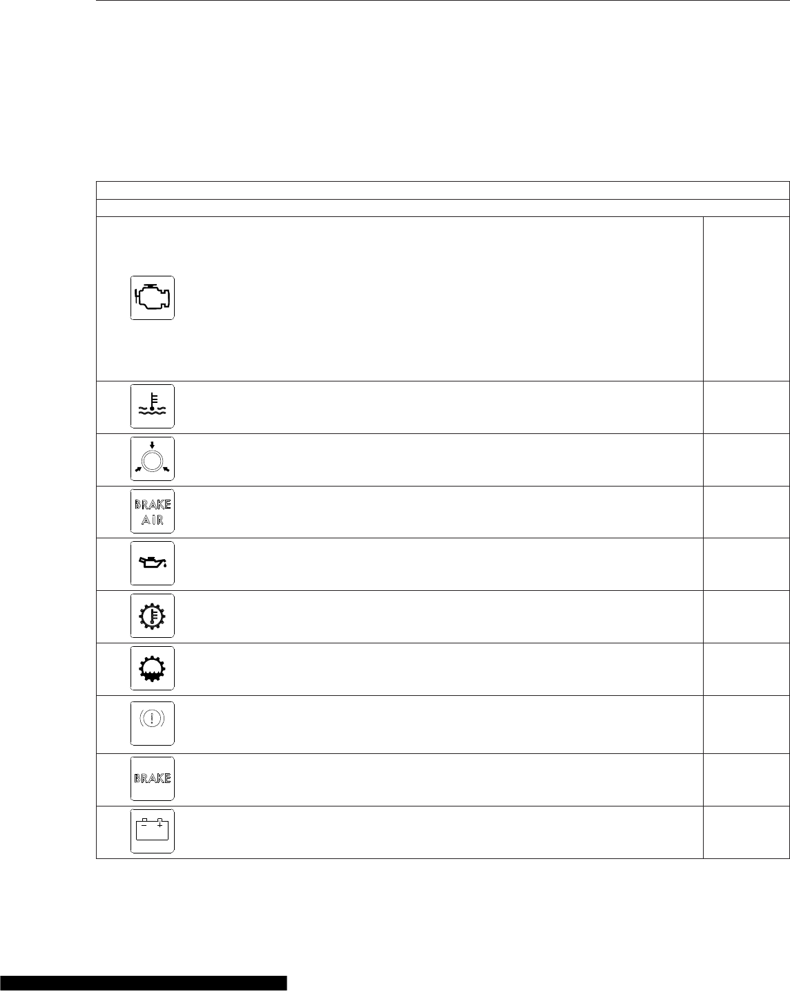
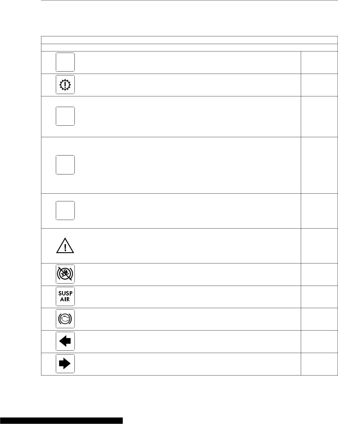
Warning and Indicator Lights
The ICU lightbar has three or four rows of warning
and indicator lights with icon symbols, depending on
the ICU. The positions of the lights may vary for the
different ICU’s, but the telltales are standard for all
applications. See Table 4.1 for a listing of standard
and commonly used warning and indicator lamps.
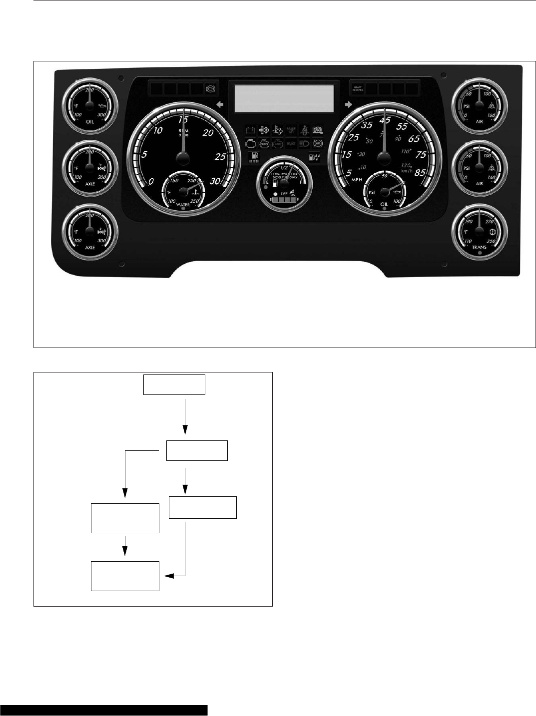
06/27/2012 f611164
1
2
3
456
7
8
9
10
1. Engine Oil Temperature Gauge
2. Front Axle Temperature Gauge
3. Rear Axle Temperature Gauge
4. Speedometer and Coolant
Temperature Gauge
5. Fuel/DEF Level Gauge
6. Tachometer and Engine Oil
Pressure Gauge
7. Primary Air Pressure Gauge
8. Secondary Air Pressure Gauge
9. Transmission Oil Temperature
Gauge
10. Driver Message Center
Fig. 4.3, ICU4Me Instrument Cluster
IGNITION SWITCH
PARKING BRAKE
RELEASED
IF NO FAULTS
WERE DETECTED
IF FAULT DETECTED
APU 190
123456.7
12.3 VOLTS
123456.7
12.3 VOLTS
MI
MI
01/18/2012 f040420c
PARKING BRAKE
RELEASED
TURNED TO ON
ICU PERFORMS
SELF−TEST
Fig. 4.4, ICU Ignition Sequence
Instruments
4.3
Warning and indicator lamps illuminate in red (dan-
ger), amber (caution), green (status advisory), or
blue (high-beam headlights active).
IMPORTANT: Depending upon local jurisdic-
tional emissions guidelines, vehicles and/or en-
gines that are domiciled outside of the U.S. and
Canada may not be compliant with EPA07,
EPA10, or GHG14 regulations. Noncompliant
vehicles may not be equipped with all of the
lamps shown in Table 4.1.
Common Warning and Indicator Lamps
Lamp Description Color
STOP
STOP Engine*
Indicates a serious fault that requires engine shutdown
immediately. The engine protection system will reduce the
maximum engine torque and speed, and, if the condition
does not improve, will shut down the engine within 30 to 60
seconds.
Safely bring the vehicle to a stop on the side of the road
and shut down the engine as soon as the red light is seen.
If the engine shuts down while the vehicle is in a
hazardous location, turn the key to the OFF position for
a few seconds, then restart the engine and move the
vehicle to a safer location.
Red
High Coolant Temperature Indicates the coolant temperature is above the maximum
allowable temperature. Red
Low Air Pressure (EPA07) Indicates air pressure in the primary or secondary reservoir
has dropped below approximately 70 psi (483 kPa). Red
Low Air Pressure (EPA10
and Newer)
Indicates air pressure in the primary or secondary reservoir
has dropped below approximately 70 psi (483 kPa). Red
Low Engine Oil Pressure Indicates the engine oil pressure is below the minimum
allowable pressure. Red
Transmission Overheat Indicates high transmission temperature. Red
Transmission Fluid Level Indicates low transmission fluid level. Safely bring the
vehicle to a stop as soon as possible. Red
BRAKE Parking Brake (EPA07)
Indicates the parking brake is engaged, or hydraulic brake
fluid pressure is low. An audible alert activates when the
vehicle is moving over 2 mph (3 km/h) with the parking
brake set.
Red
Parking Brake (EPA10
and Newer) Indicates the parking brake is engaged. Red
Low Battery Voltage Indicates that battery voltage is 11.9 volts or less. Red
Instruments
4.4
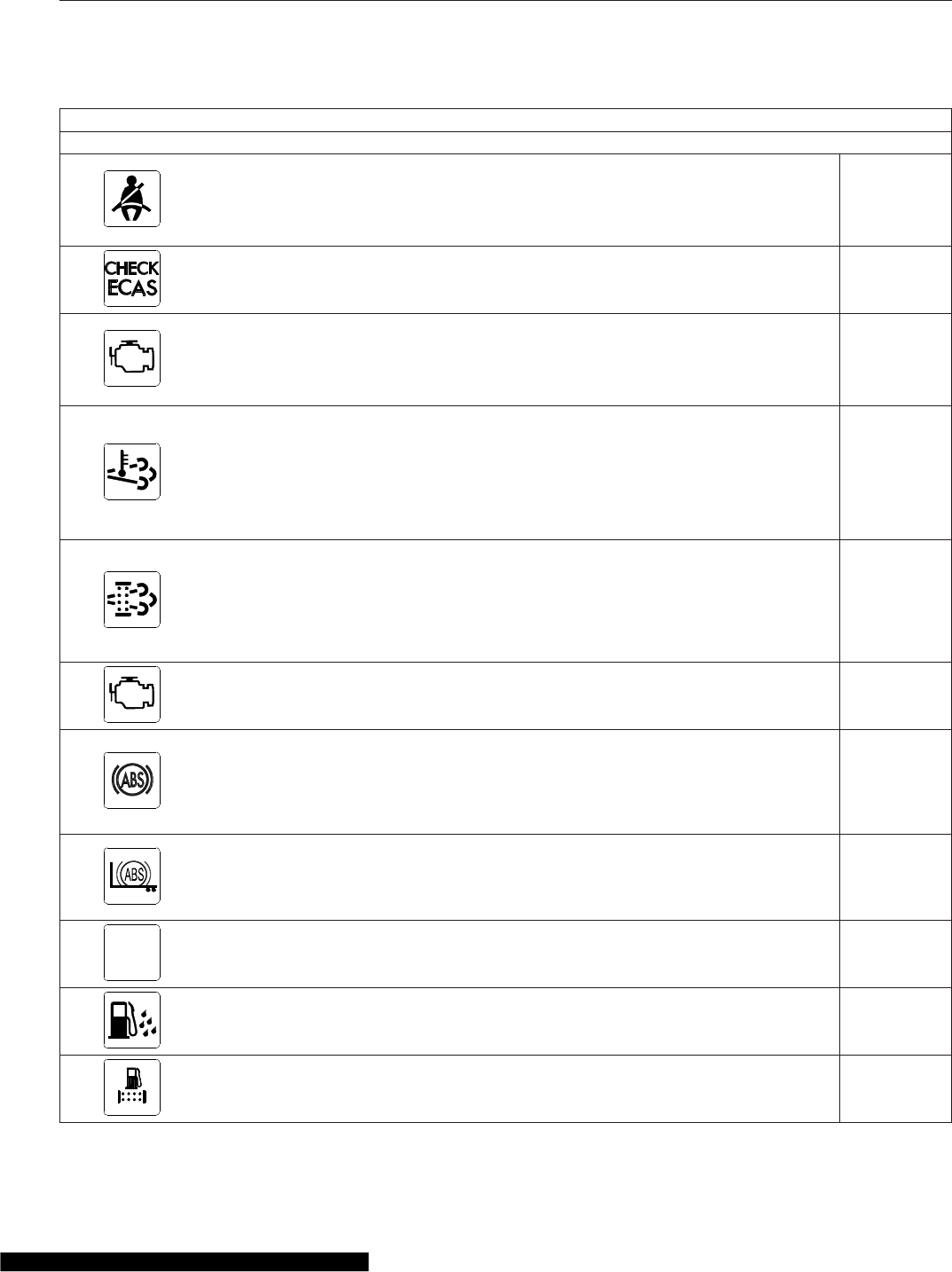
Common Warning and Indicator Lamps
Lamp Description Color
Unfastened Seat Belt
Activates with an audible alert when the system detects that
the parking brake is off and the driver seat belt is not
fastened on some vehicles. On other vehicles, this lamp
illuminates for 15 seconds when the ignition is first turned
on.
Red
Check ECAS Indicates Electronically Controlled Air Suspension (ECAS)
active fault. Red
CHECK
CHECK Engine*
Indicates an engine condition (low oil pressure, low coolant
level, high coolant temperature, high DPF soot level, or
uncontrolled DPF regeneration) that requires correction.
Correct the condition as soon as possible. If the condition
worsens, the STOP engine lamp will illuminate.
Amber
High Exhaust System
Temperature (HEST)*
Slow (10-second) flashing indicates a regeneration (regen)
is in progress.
IMPORTANT: When the HEST lamp is illuminated, do
not park the vehicle near flammable material.
Solid illumination indicates high exhaust temperatures at the
outlet of the tail pipe when speed is below 5 mph (8 km/h).
Amber
Diesel Particulate Filter
(DPF) Status
Solid illumination indicates a regen is required. Change to a
more challenging duty cycle (such as highway driving ) to
raise exhaust temperatures for at least twenty minutes, or
perform a parked regen.
Blinking indicates that a parked regen is required
immediately. An engine derate and shutdown will occur.
Amber
Malfunction Indicator
Lamp (MIL)
Indicates an emissions-related fault. See the engine
operation manual for details. Amber
Vehicle ABS
Momentary illumination indicates the vehicle ABS is
engaged.
Solid illumination indicates a problem with the vehicle ABS.
Repair the ABS immediately to ensure full braking
capability.
Amber
Trailer ABS
Momentary illumination indicates the trailer ABS is engaged.
Solid illumination indicates a problem with the trailer ABS.
Repair the ABS immediately to ensure full braking
capability.
Amber
NO
CHARGE No Charge Indicates the alternator is not properly powering the
electrical system. Amber
Water in Fuel Indicates the fuel may contain water. Drain any water
collected in the fuel/water separators. Amber
Fuel Filter Restriction Indicates the fuel filter is clogged and requires service. Amber
Instruments
4.5
Common Warning and Indicator Lamps
Lamp Description Color
IDLE
MGMT
Optimized Idle Indicates optimized idle is enabled. Amber
Check Transmission Indicates an undesirable transmission condition. Amber
WAIT
TO START
Wait To Start (EPA07/
EPA10)
Indicates that the system is preventing the starter from
cranking. This can occur when the ignition switch is turned
to START before the gauge sweep has completed, or if the
starter has overheated.
Turn the ignition switch back to ON, wait for the lamp to go
out, then turn the ignition switch to START again.
Amber
START
BLOCKED
Start Blocked (GHG14)
Indicates that the system is preventing the starter from
cranking. This can occur when the ignition switch is turned
to START before the gauge sweep has completed, or if the
starter has overheated.
NOTE: Illumination of the Start Blocked lamp does not
indicate a problem with the starter.
Turn the ignition switch back to ON, wait for the lamp to go
out, then turn the ignition switch to START again.
Amber
WHEEL
SPIN Wheel Spin
Flashing indicates the ATC system is active, or the ATC
button has been pressed to allow wheel slip.
Solid illumination indicates a problem with the ATC system.
Repair the ATC system immediately to ensure full braking
capability.
Amber
Roll Stability
Momentary illumination indicates that a stability event has
occurred.
On vehicles that are also equipped with ATC, flashing
indicates the ATC button has been pressed to allow wheel
slip.
Amber
Hill Start Aid (HSA)
Override
Indicates the HSA switch has been pressed to override the
hill start assist feature. Amber
Outside Normal Ride
Height
Indicates the current rear suspension height is not at the
normal ride height. This light will turn off once the vehicle
returns to normal ride height.
Amber
Engine Brake Indicates the engine brake is enabled. Green
Left-Turn Signal Flashing indicates the outside left-turn signal lights are
activated. Green
Right-Turn Signal Flashing indicates the outside right-turn signal lights are
activated. Green
Instruments
4.6
Common Warning and Indicator Lamps
Lamp Description Color
Cruise Control
Indicates the cruise control is enabled.
NOTE: The ICU4Me does not have a green cruise control
telltale.
Green
High-Beam Headlights Indicates the high-beam headlights are on. Blue
*See Fig. 4.5 for an explanation of the aftertreatment system (ATS) warning indicators, and actions required to avoid further engine protection steps.
Table 4.1, Common Warning and Indicator Lamps
Engine Protection System
WARNING
When the red STOP engine lamp illuminates,
most engines are programmed to shut down au-
tomatically within 30 seconds. The driver must
immediately move the vehicle to a safe location
at the side of the road to prevent causing a haz-
ardous situation that could cause bodily injury,
property damage, or severe damage to the en-
gine.
See Fig. 4.5 for an explanation of the aftertreatment
system (ATS) warning indicators, and actions re-
quired to avoid further engine protection steps.
The STOP engine lamp illuminates when the engine
protection system is activated in one of two ways. On
some engines, the engine protection system will der-
ate the engine, allowing it to run at lower rpm and
slower vehicle speed. Drive the vehicle to a safe lo-
cation or to a service facility.
IMPORTANT: Safely bring the vehicle to a stop
on the side of the road and shut down the en-
gine as soon as the red light is seen. If the en-
gine shuts down while the vehicle is in a haz-
ardous location, turn the key to the OFF position
for a few seconds, then restart the engine and
move the vehicle to a safer location.
On other engines, the engine protection system will
shut down the engine. It will first derate the engine,
then shut it down completely 30 to 60 seconds after
the indicator illuminates (depending on the critical
fault type) if the condition does not improve. Bring
the vehicle to a stop on the side of the road before
the engine shuts down.
Some vehicles may have a shutdown-override
switch, which may be used to momentarily override
the shutdown sequence. See Chapter 11 for detailed
information regarding the shutdown process.
IMPORTANT: Do not attempt to restart the en-
gine while the vehicle is moving. Bring the ve-
hicle to a safe stop, then restart the engine.
To restart the engine, turn the ignition to OFF, leave
it there a few seconds, then turn the ignition to
START. The engine will run for a short period and
shut down again if the condition does not improve.
Instruments
Standard instruments are present on every vehicle.
They are listed here in alphabetical order to make
the information easier to find.
Optional instruments, typically located on the auxil-
iary dash panel or right-hand control panel, are not
found on every vehicle. They are listed here in alpha-
betical order, to make the information easier to find.
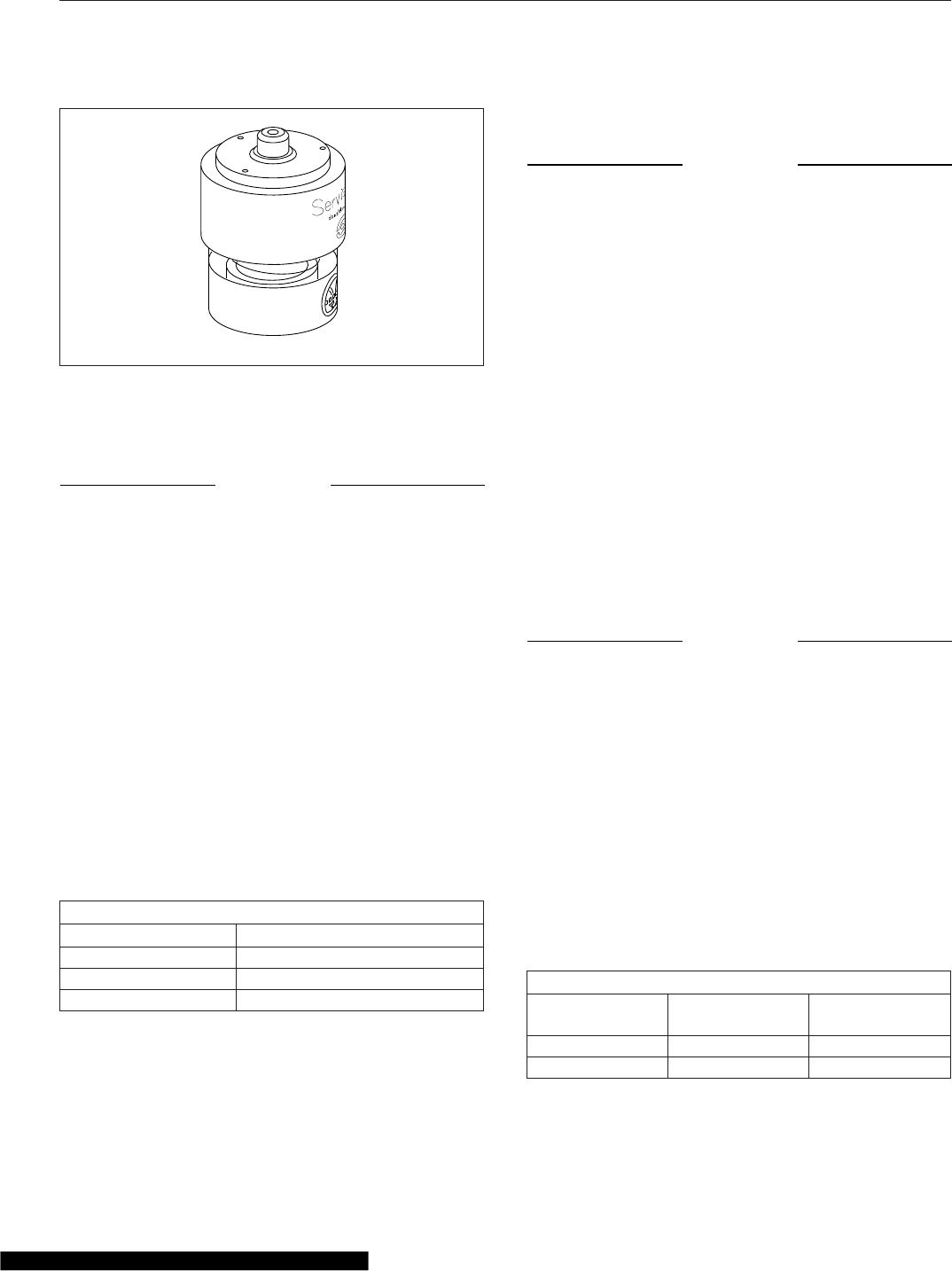
Air Intake Restriction Gauge
The air intake restriction gauge indicates the vacuum
on the engine side of the air cleaner. On standard
installations, it is mounted on the air intake duct in
the engine compartment. As an option for easier
viewing, the air intake restriction indicator (see
Fig. 4.6) can be mounted on the dash, usually on the
right-hand control panel.
NOTE: Rain or snow can wet the filter and
cause a temporary high reading.
Air intake restriction vacuum is measured in inches
of water (inH
2
O). For vehicles equipped with a
graduated indicator or a restriction gauge on the
Instruments
4.7
dash, check the gauge with the engine off. If the yel-
low signal stays locked in the red zone once the en-
gine is shut down, or is at or above the values
shown in Table 4.2, the air cleaner element needs to
be replaced.
Vehicles may be equipped with a go/no-go restriction
indicator without graduations (see Fig. 4.7) instead of
agraduated indicator.
Air Intake Maximum Restriction Values (inH
2
O)
Engine Make Pre-EPA07
Engines
EPA07 and
Newer Engines
Cummins 25 25
Detroit 20 22
Mercedes-Benz 22 22
Table 4.2, Air Intake Maximum Restriction Values
Application Air Pressure Gauge
An application air pressure gauge registers the air
pressure being used to apply the brakes, and should
be used for reference only. The gauge will not regis-
ter air pressure until the foot brake pedal is de-
pressed or the trailer hand brake is applied.
f080156
EXHAUST AFTERTREATMENT SYSTEM INFORMATION
Switch.
Level 1 Level 3Level 2 Level 4
Filter Regeneration
Recommended.
Filter is reaching
Bring vehicle to
highway speeds to
Filter
Regeneration
Filter is now
reaching maximum
capacity
.
To avoid engine
derate, bring vehicle
Parked Regeneration
Required − Engine
Derate
Filter has reached
maximum capacity
.
Vehicle must be
parked, and a Parked
Service Regeneration Required.
Engine Derate To Idle Only.
Filter has exceeded maximum
capacity.
Vehicle must be parked, and a
Service Regeneration must be
(Solid)
(Flashing) (Flashing)
CHECK
INDICATOR
LAMP(S)
Indicator Lamp
Message(s)
Diesel Particulate
Filter Condition
Required Action
capacity
.
STOP
allow for an
Automatic
Regeneration or
perform a Parked
to highway speeds
to allow for an
Automatic
Regeneration, or
perform a Parked
Regeneration as
soon as possible.
Regeneration must
be performed.
Engine will begin
derate.
performed. Check engine
operator’s manual for details.
Engine will shut down.
For a driver performed Parked Regeneration, vehicle must be equipped with a dash mounted Regeneration Switch.
02/20/2009
W
ARNING
HEST (High Exhaust
System Temperature)
Exhaust components
and exhaust gas are at
high temperature. When
stationary, keep away
from people and
flammable materials or
vapors.
A regeneration is in
progress.
Flashing
Solid
Regeneration.
Necessary
Fig. 4.5, ATS Warning Lamps
10/10/2001 f610568
Fig. 4.6, Air Intake Restriction Indicator
Instruments
4.8
Coolant Temperature Gauge
NOTICE
A sudden increase in coolant temperature may
indicate engine or cooling system failure. Bring
the vehicle to a safe stop and investigate the
cause to prevent further damage. Do not operate
the engine until the cause has been determined
and corrected.
During normal engine operation, the coolant tem-
perature gauge should read 175 to 195°F (79 to
91°C). If the temperature remains below 160°F
(71°C), inspect the cooling system to determine the
cause.
If coolant temperature rises above the maximum
temperature listed in Table 4.3, the CHECK engine
lamp will illuminate. If the condition does not im-
prove, the STOP engine lamp will also illuminate and
an audible warning will sound. The engine will then
derate or shut down, depending on the type of en-
gine protection system installed.
Maximum Coolant Temperature
Engine Make Temperature: °F (°C)
Cummins 225 (107)
Detroit 215 (101)
Mercedes-Benz 221 (105)
Table 4.3, Maximum Coolant Temperature
Drive Axle Oil Temperature Gauges
NOTICE
A sudden increase in oil temperature that is not
caused by a load increase may indicate mechani-
cal failure. Bring the vehicle to a safe stop and
investigate the cause to prevent further damage.
Do not operate the vehicle until the cause has
been determined and corrected.
During normal operation, drive axle oil temperature
gauges should read as follows:
•160 to 220°F (71 to 104°C) for Detroit™and
Meritor™drive axles
•180 to 200°F (82 to 93°C) for Dana Spicer®
drive axles
Under heavy loads, such as when climbing steep
grades, temperatures that exceed the normal oil tem-
perature range for a short period are not unusual. If
the temperature returns to normal when the load de-
creases, there is no problem.
Engine Oil Pressure Gauge
NOTICE
A sudden decrease or absence of oil pressure
may indicate mechanical failure. Bring the vehicle
to a safe stop and investigate the cause to pre-
vent further damage. Do not operate the engine
until the cause has been determined and cor-
rected.
The engine oil pressure gauge displays the current
engine oil pressure. If engine oil pressure falls below
the minimum levels shown in Table 4.4, the CHECK
engine lamp will illuminate. If the condition does not
improve, the STOP engine lamp will also illuminate
and an audible warning will sound. The engine will
then derate or shut down, depending on the type of
engine protection system installed.
Minimum Oil Pressure*
Engine Model At Idle Speed:
psi (kPa)
At Rated RPM:
psi (kPa)
Cummins 15 (103) 35 (241)
Detroit 14 (97) 55 (350)
04/08/2005 f090431
Fig. 4.7, Manual-Reset Air Restriction Indicator, Go/
No-Go
Instruments
4.9
Minimum Oil Pressure*
Engine Model At Idle Speed:
psi (kPa)
At Rated RPM:
psi (kPa)
Mercedes-Benz 7 (50) 36 (250)
*Oil pressures are given with the engine at operating temperature. With
the engine cold, oil pressure may be higher. Individual engines may vary
from the listed pressures; observe and record pressures when the engine
is new to create a guide for checking engine condition.
Table 4.4, Minimum Engine Oil Pressure
Engine Oil Temperature Gauge
NOTICE
A sudden increase in oil temperature that is not
caused by a load increase may indicate mechani-
cal failure. Bring the vehicle to a safe stop and
investigate the cause to prevent further damage.
Do not operate the engine until the cause has
been determined and corrected.
During normal operation, the optional engine oil tem-
perature gauge should read:
•200 to 260°F (93 to 126°C) for Detroit and
Cummins engines
•177 to 203°F (81 to 95°C) for Mercedes-Benz
engines
Under heavy loads, such as when climbing steep
grades, temperatures that exceed the normal oil tem-
perature range for a short period are not unusual. If
the temperature returns to normal when the load de-
creases, there is no problem.
Fuel Gauge, Pre-EPA10
The fuel gauge indicates the level of fuel in the fuel
tank(s). A single fuel gauge is standard. If equipped
with an optional second fuel tank, each fuel tank
level is indicated on a separate gauge.
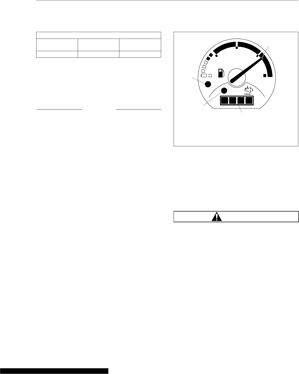
Fuel/Diesel Exhaust Fluid (DEF)
Gauge, EPA10 and Newer
For engines that are EPA10-compliant or newer, the
fuel and DEF levels are measured in a dual purpose
fuel/DEF level gauge. See Fig. 4.8.
The diesel fuel level is indicated at the top of the
gauge, with a low-fuel warning lamp that illuminates
amber when the diesel fuel level registers 1/8th of
capacity.
The DEF level is indicated in the lightbar on the
lower portion of the gauge. There is a low DEF level
warning lamp that illuminates amber when the DEF
level reaches 10% of capacity. See Chapter 12 for
details of the DEF gauge functions.
Primary and Secondary Air Pressure
Gauges
WARNING
If air pressure falls below minimum pressure, the
braking ability of the vehicle will be limited. Slow
the vehicle down and bring it to a gradual stop.
Do not attempt to move the vehicle until air pres-
sure has risen above the minimum level. Moving
a vehicle without adequate braking power could
cause an accident resulting in property damage,
personal injury, or death.
Air pressure gauges register the pressure in the pri-
mary and secondary air systems. Normal pressure,
with the engine running, is 100 to 120 psi (689 to
827 kPa) in both systems.
A low-air-pressure warning light and audible alert,
connected to both the primary and secondary sys-
tems, activate when air pressure in either system
drops below approximately 70 psi (483 kPa).
08/21/2009
1/2
ULTRA LOW SULFUR
DIESEL FUEL ONLY
EF
DEF
FE
f611045
1
2
3
4
1. Diesel Fuel Level Indicator
2. DEF Level Indicator
3. Low DEF Warning Lamp (amber below 10% DEF)
4. Low Fuel Warning Lamp (amber at 1/8 tank of fuel)
Fig. 4.8, Fuel/DEF Gauge, EPA10 and Newer
Instruments
4.10

When the engine is started, the warning light and
audible warning remain on until air pressure in both
systems exceeds minimum pressure.
Speedometer
Two speedometer options are available. The U.S.
version of the speedometer registers speed in both
miles per hour (mph) and kilometers per hour (km/h),
with mph in larger numbers. The metric version of
the speedometer face reverses this arrangement,
with km/h in larger numbers.
Tachometer
The tachometer indicates engine speed in revolutions
per minute (rpm) and serves as a guide for shifting
the transmission and keeping the engine in the ap-
propriate rpm range. For low idle and rated rpm, see
the engine identification plate.
Transmission Fluid Temperature
Gauge
The transmission fluid temperature gauge indicates
the transmission lubricant operating temperature.
Temperatures vary by application, but the transmis-
sion fluid temperature gauge reading should not ex-
ceed 250°F (121°C).
NOTICE
A sudden increase in transmission fluid tempera-
ture that is not caused by a load increase may
indicate mechanical failure. Bring the vehicle to a
safe stop and investigate the cause to prevent
further damage. Do not operate the vehicle until
the cause has been determined and corrected.
Under heavy loads, such as when climbing steep
grades, temperatures that exceed the normal oil tem-
perature range for a short period are not unusual. If
the temperature returns to normal when the load de-
creases, there is no problem.
Turbocharger Boost Pressure Gauge
A turbocharger boost pressure gauge indicates the
pressure in the intake manifold, in excess of atmos-
pheric pressure, being created by the turbocharger.
Voltmeter
The voltmeter indicates the vehicle charging system
voltage when the engine is running and the battery
voltage when the engine is off. By monitoring the
voltmeter, the driver can stay aware of potential bat-
tery charging problems and have them fixed before
the batteries discharge enough to create starting diffi-
culties. Cascadia vehicles are equipped with either a
voltmeter gauge, or a digital voltmeter readout lo-
cated on the bottom line of the dash message center.
The voltmeter will normally show approximately 13.7
to 14.1 volts when the engine is running. The voltage
of a fully charged battery is 12.7 to 12.8 volts when
the engine is off. Battery voltage under 12.0 volts is
considered a low battery, and a completely dis-
charged battery will produce only about 11.0 volts.
If the voltmeter shows an undercharged or over-
charged condition for an extended period, have the
charging system and batteries checked at an autho-
rized Freightliner service facility.
On a vehicle equipped with a battery isolator system,
the voltmeter measures the average voltage of all the
batteries when the engine is running. When the en-
gine is off, the voltmeter shows only the isolated bat-
tery voltage and does not indicate the voltage of the
engine-starting batteries.
Driver Message Center
ICU3/ICU4
The driver message center is controlled using the
mode/reset switch, located on the right side of the
ICU, and the +and –buttons mounted in the right-
hand pod of the steering wheel (Fig. 4.9). See
Fig. 4.1 and Fig. 4.9. Tap the mode/reset switch or
the +switch to advance one screen; press and hold
either switch to select a menu choice or reset the
display. When the display resets, an audible chirp
sounds.
Four driving screens are accessible when the parking
brake is off. All screens and menus are accessible
when the parking brake is on (parked screens).
Driving Screens
The following screens are available when the parking
brake is off (when the vehicle is mobile) and no ac-
tive fault codes are found. Use the +and –switches
on the steering wheel, or the mode/reset switch, to
Instruments
4.11
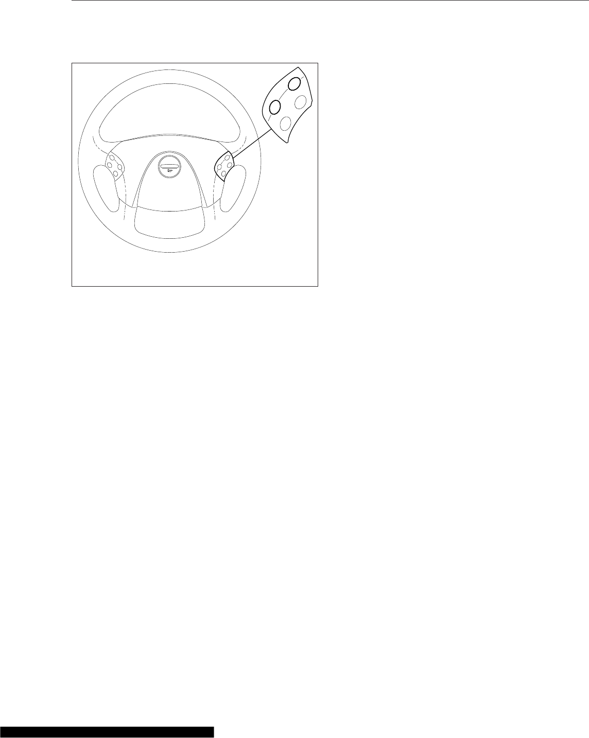
scroll through the screens. To reset any values,
press and hold the +switch or the mode/reset
switch. The driving screens appear in the following
order:
i. Odometer
ii. Trip distance
iii. Trip hours
iv. Outside temperature
Parked Screens/Menus
The following screens and menus are available when
the parking brake is on (when the vehicle is parked)
and no active fault codes are found. Use the +and –
switches on the steering wheel, or the mode/reset
switch, to scroll through the driving screens. To reset
any values, press and hold the +switch or the mode/
reset switch. See Fig. 4.10. The parked screens ap-
pear in the following order:
i. Odometer
ii. Trip distance
iii. Trip hours
iv. Outside temperature
v. Temperature alert
vi. Diagnostics
vii. Clear screen (on vehicles with less than 255
miles on the odometer)
viii. Engine miles/hours
ix. Setup
Temperature Alert
When the outside temperature drops to 35°F (1.7°C)
or less, the ICU displays a caution text at one-
second intervals for five seconds, and an audible
alert sounds. Tap the +or –switch on the steering
wheel, or the mode/reset switch, to acknowledge the
message. The audible alert will not sound again un-
less the temperature cycles above 37°F (4°C) and
back to 35°F (1.7°C) or less. This warning only oc-
curs while the ignition is on and the parking brake is
released.
The temperature alert message allows the driver to
enable or disable the ambient temperature warning.
Press and hold the mode/reset switch to toggle be-
tween on and off. Release the mode/reset switch,
then tap it to select the displayed choice.
Diagnostics
When the DIAG screen is displayed, press and hold
the mode/reset switch to access the various diagnos-
tic screens. See Fig. 4.11 for a diagram of the diag-
nostic screens.
The diagnostic screens are used by trained techni-
cians to retrieve fault codes and other diagnostic in-
formation pertaining to the vehicle. If active fault
codes display during start-up or at any other time,
make a note of the fault code and take the vehicle to
an authorized Freightliner service facility
If fault codes are displayed, press and hold the
mode/reset switch to view the next fault code until
reaching the DIAG screen.
Engine Miles/Hours
When the engine miles/hours screen is displayed,
press and hold the mode/reset switch to access the
engines screen submenu. See Fig. 4.11 for a dia-
gram of the engine screens.
MRKR
INT
ENG
BRK
−
+
02/06/2007 f462061
NOTE: To reset values in the ICU4M and ICU4Me driver
message centers, press and hold the +switch.
Fig. 4.9, Steering Wheel-Mounted Switches
Instruments
4.12
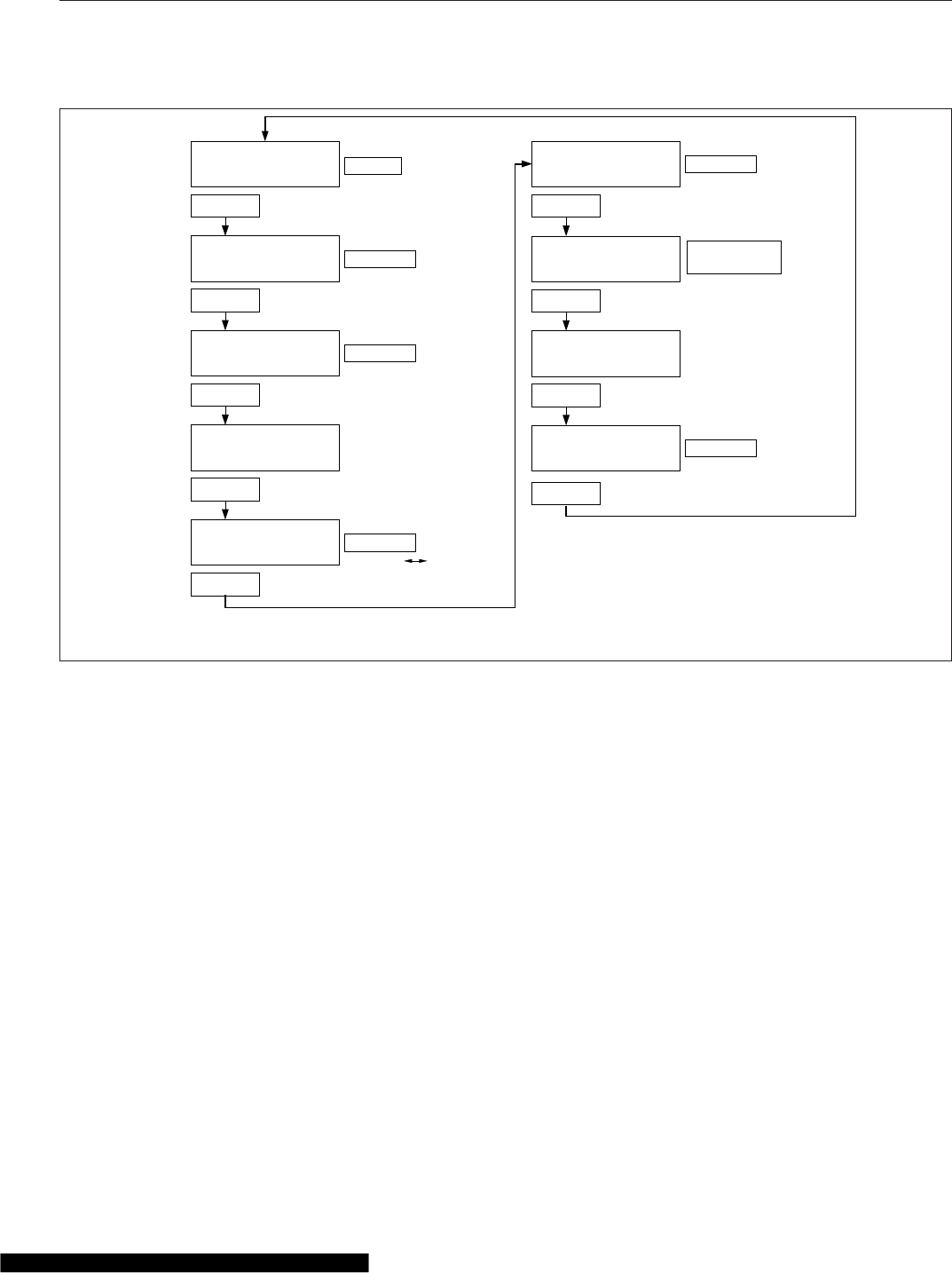
Setup
The setup menu allows the driver to manage ICU
parameters. The setup screen submenu allows the
driver to enable and change service intervals. See
Fig. 4.12.
If service intervals are enabled and service distance
or time has been exceeded, the text SERVICE
HOUR/MI (KM) will display at start-up to indicate ve-
hicle service is required.
For each parameter, press and hold the mode/reset
switch to navigate to the parameter change screen.
In each change screen, tap the mode/reset switch to
toggle between options.
Use the last screen in the setup menu, RESET EE,
to reset the parameters the ICU learns back to the
default settings. Press and hold the mode/reset
switch to reset the following learned parameters:
•automated transmission display
•seat belt switch learning
•engine oil level
•other electronic devices that have been re-
moved from the vehicle (e.g. Qualcomm)
ICU4M
Functions
ICU4M settings and the driver message center are
controlled with the +and –switches and the MY
INFO switch, mounted on the dash. See Fig. 4.13.
Tap the MY INFO switch to drill down from each
main screen to the submenus contained within it.
Use the +and –switches to scroll through screens
and select options. Tap the MY INFO switch again to
exit each change screen.
With the parking brake off, only the odometer and
alert messages can be displayed. Park the vehicle
and set the parking brake to access the parked
screens and menus.
01/30/2012 f040754
123456.7
TRIP MI
12.3 VOLTS
Tap
123456.7
MI
12.3 VOLTS
Tap
123456.7
TRIP HOURS
12.3 VOLTS
ALrt
n
123456.7
HOURS
ENGINE
oiL
*Lo
SEtUP
**MI **HOURS
**no
To reset trip miles
Press & Hold
To reset trip hours
Press & Hold
Display service
interval screens
Press & Hold
Press & Hold
Tap
To toggle ON
*Lo = Oil Level Low
HI = Oil Level High
Blank = Oil Level OK
− − = No Message
**MI = Miles Interval Mode
**HOURS = Hours Interval Mode
**no = Service Interval Inactive
dIAG
MI HOURS
n
Display diagnostics
Press & Hold
n = Number of Active Fault Codes
MI = Miles Interval Mode
HOURS = Hours Interval Mode
°t
ENGINE
Tap
Tap
Tap
Tap
Tap
Tap
12.3 VOLTS
56°F
OFF
Odometer
To display total
engine miles/hours
Note: The engine oil level screen displays for Mercedes-Benz engines only (if equipped and enabled).
Fig. 4.10, ICU3 Parked Screens
Instruments
4.13
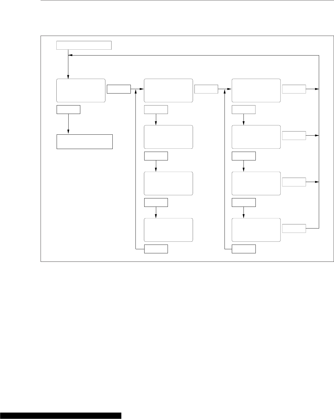
Alert Messages
The driver message center displays alert messages
when certain conditions occur. They are warnings,
cautions, or other messages that require the driver’s
attention, but not all of them are critical to the opera-
tion of the vehicle.
NOTE: If there is more than one alert message
to display, tap the +switch or the MY INFO
switch to access the next message, and so on,
until all messages have been viewed.
More important messages take priority over less im-
portant messages. The order of priority is:
1. parking brake set (with the vehicle moving)
2. parking brake off (with the door open)
3. low oil pressure or high coolant temperature
4. hard brake warnings (if equipped with roll stabil-
ity advisor)
5. low battery voltage
6. ambient temperature below 35°F (1.7°C)
7. turn signal on
8. incoming instant or Qualcomm messages
9. service warnings
f040802
From Temp Alert Screen
Press & Hold
Tap
Press & Hold
Tap
Press & Hold
Tap
n = Number of
Active Fault Codes
dlAG
n
*FAULT
01
*If fault goes inactive,
display "noFault 1"
*FAULT
nn
*If fault goes inactive,
display "noFault n"
To Setup Screen (or Oil
Level Screen, if equipped)
Press & Hold
AbS 11 ECU 0
Tap Tap
Press & Hold
123456
Tap Tap
Press & Hold
FAIL 03 FAIL 00
Tap Tap
SPN SPN
123456
01/31/2012
Fig. 4.11, ICU4 Diagnostic Screens
Instruments
4.14
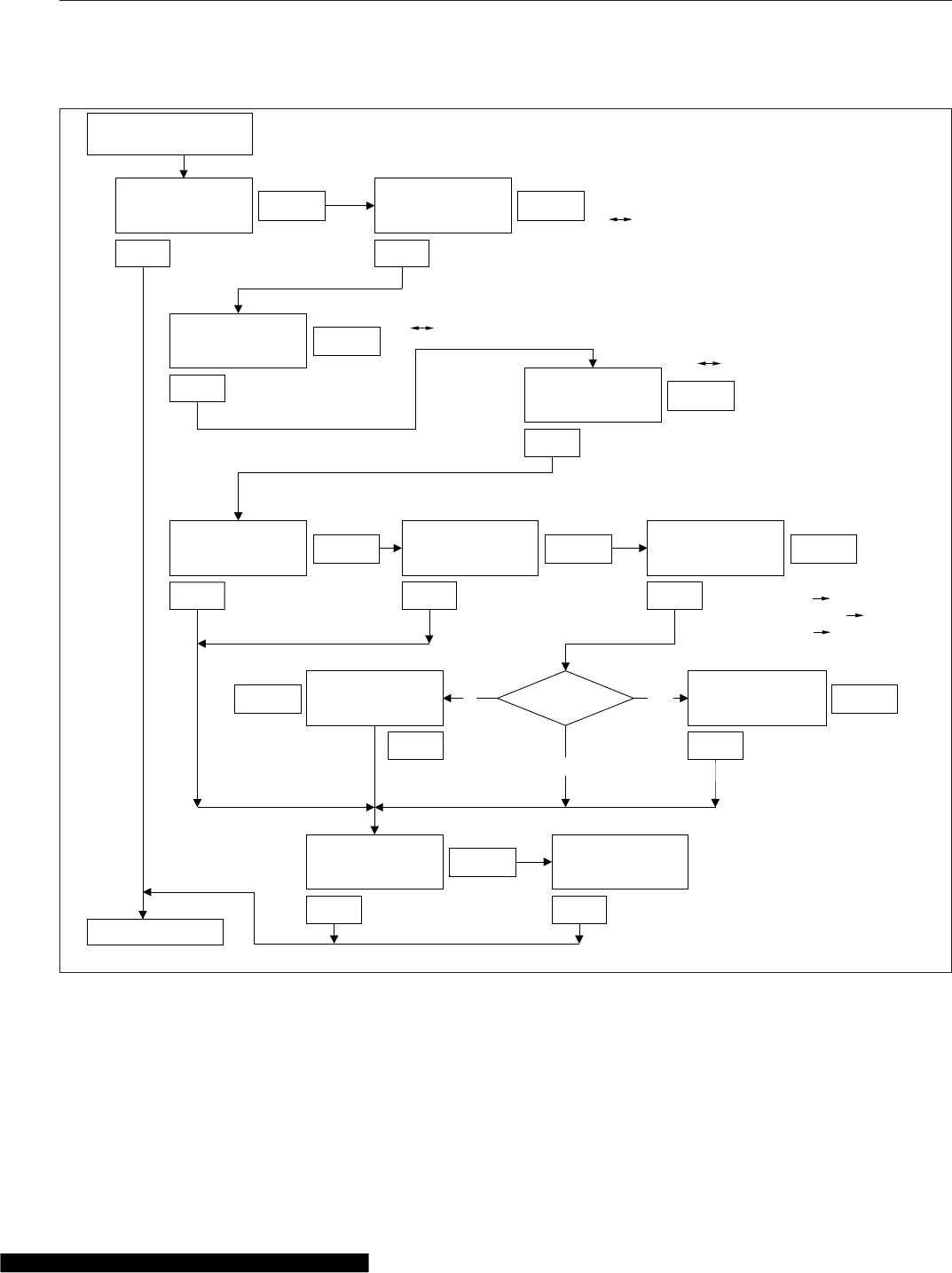
10. no datalink activity Incoming Message
On vehicles with a Qualcomm onboard communica-
tions system, a notification appears on the driver
message center whenever a message is received.
Selection?
To toggle
MI
HOURS
no
NOTE:
* Flash screen text
**Display active mode
Select NO
to disable
Service Intervals
Press & Hold to reset all
Service Interval counters
To toggle
MI
To toggle
Tap
To toggle
ON
HRS
MI
no
Tap
TapTap
Tap Tap Tap
Tap
Tap
TapTap
Press & Hold
Press & Hold
Press & Hold
Press & Hold
Press & Hold Press & Hold Press & Hold
Press & HoldPress & Hold
Press & Hold
SET UP SELECT
*MI
SET UP
WARN°T
*on
LCD LMP
*on
**MI **HOURS
**no
RESET
**MI **HOURS
*no
SELECT
*MI *HOURS
*no
SERVICE SERVICE SERVICE
*12345
MI
SERVICE
*12345
HOURS
SERVICE
RESET
EE
DONE
f040755
01/30/2012
OFF
KM
ON OFF
To Odometer
From Engine
Miles/Hours Screen
Fig. 4.12, ICU4 Setup Screens
Instruments
4.15

NOTE: The incoming message screen also dis-
plays during the ignition sequence if a message
is available.
This message displays for a preset time period, then
returns after a preset interval until it is dismissed by
the +and –switches or the MY INFO switch.
Parking Brake On
This warning message and an audible warning come
on whenever the parking brake is applied and the
vehicle is moving faster than 2 mph (3 km/h). See
Fig. 4.14. The screen and audible warning go away
only when the parking brake is released, or speed is
reduced below 2 mph.
Low Oil Pressure
This warning message and an audible warning come
on whenever the oil pressure falls below the mini-
mum oil pressure, whether the vehicle is idling or in
motion. Tap the +and –switches or the MY INFO
switch to dismiss the message.
If low oil pressure is detected during the ignition se-
quence, it displays as an active fault instead of an
alert message. After 30 seconds, the message dis-
plays again.
High Coolant Temp
This message and an audible warning come on
whenever the engine coolant temperature exceeds
the maximum allowable temperature.
If high coolant temperature is detected during the
ignition sequence, it displays as an active fault in-
stead of an alert message. After 30 seconds, the
message displays again.
Low Voltage
On some vehicles, this optional message and an au-
dible warning come on whenever a low voltage con-
dition is detected.
Turn Signal On
This warning message and audible warning come on
whenever the turn signal remains on for four minutes
or five miles of travel. To dismiss this message, ei-
ther turn off the turn signal or tap the +and –
switches or the MY INFO switch.
Air Temperature
When the outside air temperature drops below 35°F
(1.7°C), a warning text is displayed at one-second
intervals for five seconds, and an audible warning will
sound. Tap the +and –switches or the MY INFO
switch to acknowledge the warning. The alert mes-
sage will not occur again unless the temperature
cycles above 37°F (4°C) and back below 35°F
(1.7°C). This warning only occurs while the ignition is
on and the parking brake is off.
Service Warnings
Service warning alerts display during the ignition se-
quence and indicate if a service interval has been
reached or exceeded and maintenance is required.
The messages may indicate the number of miles
(KM) or hours until the next required service or, once
passed, the number of miles (KM) or hours since
maintenance should have been performed.
Automated Transmission Display
The ICU4M can display current gear information for
vehicles with an automated transmission. The last
three digits at the far right on the lower line of the
driver message center are reserved for this informa-
tion.
02/22/2007
MY
INFO
f610887a
Fig. 4.13, MY INFO Switch
f601414
WARNING
PARK BRAKE ON
06/21/2007
Fig. 4.14, Parking Brake On Alert Message
Instruments
4.16
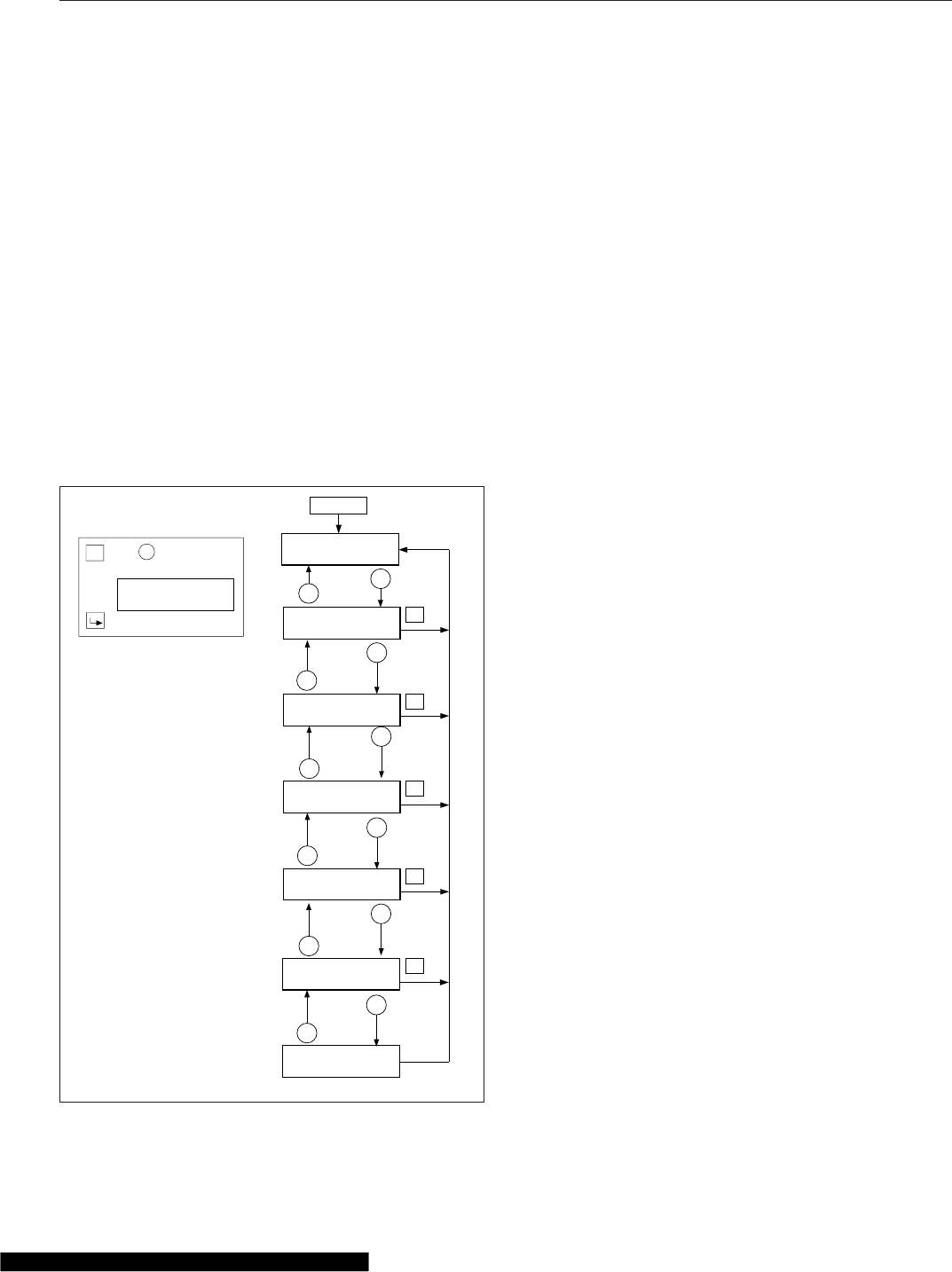
When a shift request is made by the driver, an up or
down arrow is also displayed, depending on the shift
direction.
For more information about specific models of auto-
mated transmissions, see Chapter 15.
Driving Screens
The following screens are available when the parking
brake is off (when the vehicle is mobile).
Tap the MY INFO switch to drill down from each
main screen to the submenus contained within it.
Use the +and –switches to scroll through screens
and select options. Tap the MY INFO switch again to
exit each change screen. See Fig. 4.15.
i. Fasten seat belt (rpm<100)
ii. Fuel economy (rpm>100)
iii. Odometer
iv. Trip distance/hours
v. Trip advisory
vi. Leg distance/hours
vii. Leg advisory
viii. Fuel used/average MPG (KM/L)
ix. Outside air temperature
Favorite Screen
The driver can set a favorite driving screen using the
MY INFO switch. Press and hold the lower half of the
MY INFO switch for just over one second to set the
current screen as the favorite screen. A chirp will
sound to verify the screen has been set.
Tap the lower half of the MY INFO switch to access
the favorite screen. Tap the MY INFO switch again to
leave the favorite screen.
NOTE: Only driving screens can be set as the
favorite screen.
Parked Screens/Menus
Tap the MY INFO switch to drill down from each
main screen to the submenus contained within it.
Use the +and –switches to scroll through screens
and select options. Tap the MY INFO switch again to
exit each change screen. Press and hold the +
switch or the upper half of the MY INFO switch to
reset the counters for trip and fuel information.
The following screens are available when the parking
brake is on (when the vehicle is parked). See
Fig. 4.16.
i. Odometer
ii. Trip information including trip miles/hours, idle
hours, average speed, leg miles/hours
iii. Fuel information including fuel used, fuel
economy, idle/PTO fuel usage
iv. Engine information including engine miles/hours,
engine/PTO gallons, oil level
v. Diagnostic information
vi. Service information including mileage or time to
next service
vii. Setup information
R
R
R
R
R
+
+
+
+
+
+
−
−
−
−
−
−
−0%III +
10.5 MPG 23456.7 MI
TRIP MILES 123456.7
TRIP HR 1234:56
TRIP ADVISORIES
123 ROLL 456 BRK
LEG MILES 123456.7
LEG HR 1234:56
LEG ADVISORIES
123 ROLL 456 BRK
FUEL USED 12345.6
AVG MPG 12:34
OUTSIDE AIR
TEMPERATURE 56F
01/30/2012 f545600a
R
=
H
o
l
dto
r
e
s
et.
P
U
S
H
+
KEY
T
O
C
O
N
F
I
R
M
C
LEA
R
C
onf
i
r
mat
i
on
sc
r
een
w
ill
d
i
s
p
l
a
y
r
i
ght afte
r
the f
i
r
s
tho
l
d.
+
My Info
Odometer
Fig. 4.15, ICU4M Driving Screens
Instruments
4.17
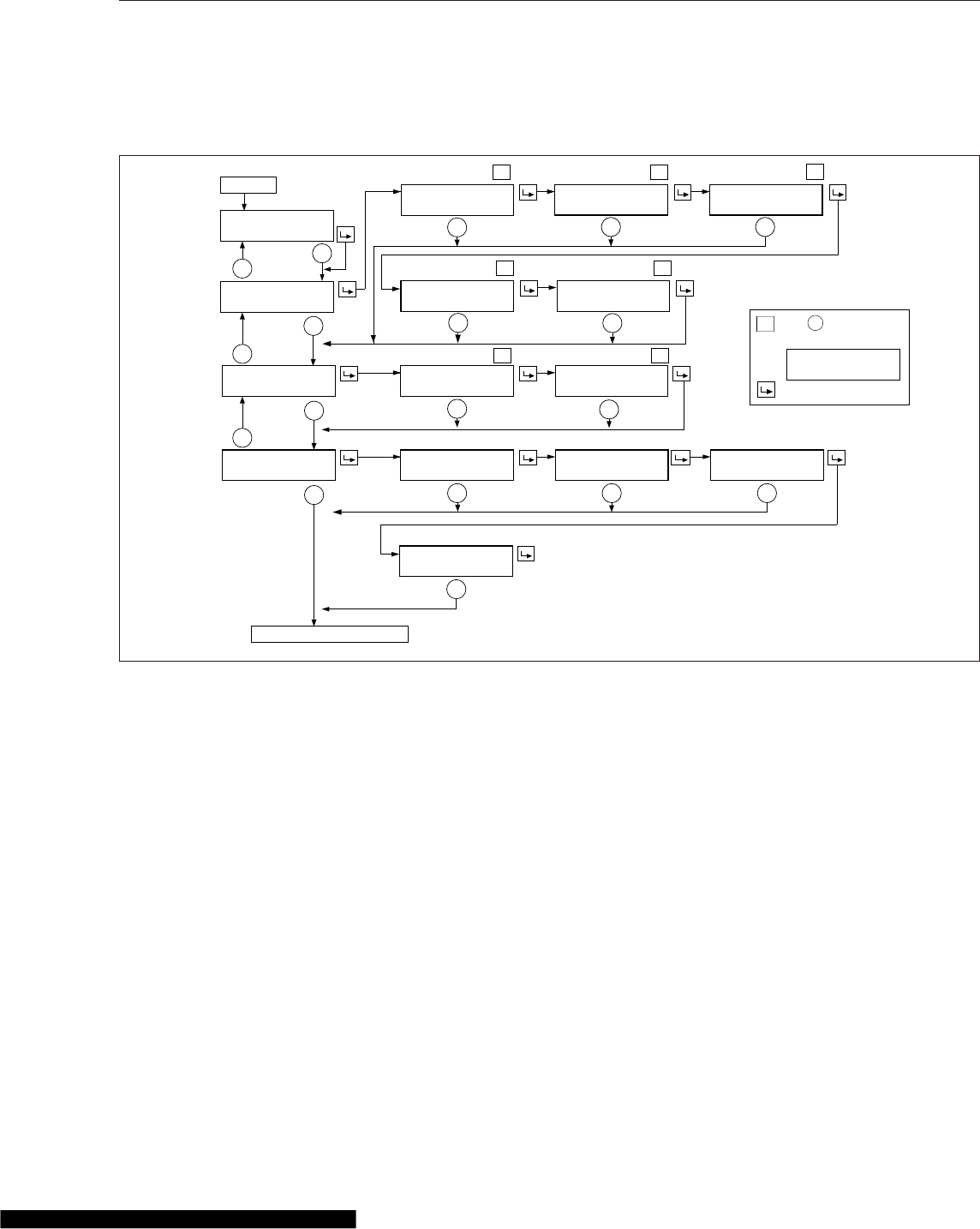
viii. Vehicle information including Datalink status, ICU
serial number, software version
ix. Outside air temperature
x. Fasten seat belt warning
Trip Information
Trip Information displays the trip miles, trip adviso-
ries, idle hours, leg miles, and leg advisories, in that
order.
Fuel Information
Fuel information displays total fuel usage since the
last reset, fuel mileage, and fuel consumed while
idling or running the PTO, in that order.
Engine Information
Engine information displays engine mileage and
hours, and total fuel consumption, in that order.
Diagnostic Information
If active fault codes are displayed on the diagnostic
information screens, make a note of the fault code
and text message, then take the vehicle to an autho-
rized Freightliner service facility See Fig. 4.17 for a
diagram of the diagnostic information screens.
Service Information
The Service Information menu displays the next ser-
vice interval, expressed in either miles or hours. See
Fig. 4.17. Service intervals can also be deactivated.
For programming service intervals, see Setup Infor-
mation, below.
NOTE: If the vehicle has exceeded the service
interval, the miles(km)/hours remaining screen
is replaced by the service was due screen, fol-
lowed by the number of miles(km)/hours since
the service was due.
IDLE HOURS 1234:56
12.3 GAL 123456.7 MI
R
RR
R
RR
R
+
+
+
−
−
−
− −
−
−
−
−
−
− − −
TRIP
INFORMATION
FUEL
INFORMATION
ENGINE
INFORMATION
TRIP MILES 123456.7
TRIP HR 1234:56
TRIP ADVISORIES
123 ROLL 456 BRK
IDLE HOURS 1234:56
AVG MPH 12.3
LEG MILES 123456.7
LEG HR 1234:56
LEG ADVISORIES
123 ROLL 456 BRK
FUEL USED 12345.6
AVG MPG 12:34
IDLE GALLONS 12345.6
PTO GAL 12345.6
ENG MILES 1234567.8
ENG HOUR 1234:56
ENG GALLONS 123456.7
PTO GAL 123456.7
OIL LVL
*Lo
f545600b
−
01/30/2012
−
85
ENGINE
PER
*Lo ENGINE
R
=
H
o
l
dto
r
e
s
et.
P
U
S
H
+
KEY
T
O
C
O
N
F
I
R
M
C
LEA
R
C
onf
i
r
mat
i
on
sc
r
een
w
ill
d
i
s
p
l
a
y
r
i
ght afte
r
the f
i
r
s
tho
l
d.
+
My Info
Odometer
To Diagnostic Information Screen
Fig. 4.16, ICU4M Idle Hours, Trip Information, Fuel Information, and Engine Information Screens
Instruments
4.18
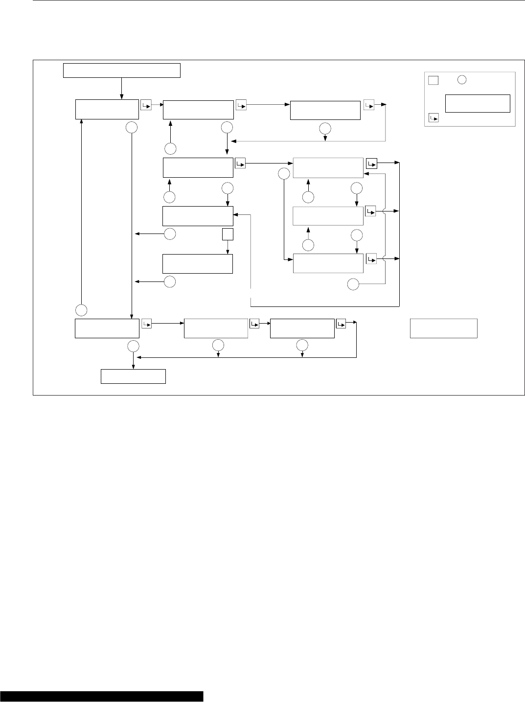
Setup Information
The Setup Information menu allows the driver to pro-
gram various features of the ICU4M. See Fig. 4.18.
The setup features include:
1. Service intervals (OFF/MILES/HOURS)
2. Outside temperature warning (ON/OFF)
3. Target MPG
4. LCD lamp (ON/OFF)
5. Driver message center brightness
6. Language (English/French/Spanish)
7. Units of measurement (English/Metric)
8. Driver select (ON/OFF)
9. Reset parameters to original settings
Vehicle Information Screens
The vehicle information screens display hardware
and software information, including the Freightliner
part number and switch ID of the ICU. See Fig. 4.19.
ICU4Me
Functions
ICU4Me settings and the driver message center are
controlled using the ICU4Me control switch located
on the dash, and the +and –switches mounted in
the right-hand pod of the steering wheel. See
Fig. 4.20 and Fig. 4.9.
The driver message center is divided into four sec-
tions. The odometer and cruise control status field
are displayed along the bottom of the message cen-
ter. When cruise control is active, the cruise control
D
I
A
G
N
O
S
T
I
C
I
N
F
O
R
M
A
T
I
O
N
A
C
T
I
VE
F
A
U
L
T
S
3
2
H
I
S
T
D
AS
H
F
A
U
L
T
S
L
AS
T
C
L
R
123456.7
+
SA(
t
e
x
t
)SA
#
SP
N
#
SP
N
(
t
e
x
t
)
F
M
I
#
LAST OCCUR 123456.7
1234 TI
M
ES
FIRST OCCUR 123456.7
1234 TI
M
ES
faults when odo
m
eter is
<
254
M
I.
M
I
LES
T
O
N
EX
T
SE
R
V
I
C
E
I
N
T
E
R
VAL
I
SSE
T
T
O
M
I
LES
HOLD
+
TO CLEAR
DASH FAULTS
A
LL
F
A
U
L
T
S
C
L
EA
R
E
D
R
+
SE
R
V
I
C
E
I
N
F
O
R
M
A
T
I
O
N
SE
R
V
I
C
E
W
AS
DU
E
M
I
LES AGO
SA(
t
e
x
t
)SA
##
SP
N
####
SP
N
(
t
e
x
t
)
F
M
I
##
2SecTi
m
eout
This will also clear other vehicle ECU’s inactive
If overdue:
R
=
H
o
l
dto
r
e
s
et.
P
U
S
H
+
KEY
T
O
C
O
N
F
I
R
M
C
LEA
R
C
onf
i
r
mat
i
on
sc
r
een
w
ill
d
i
s
p
l
a
y
r
i
ght afte
r
the f
i
r
s
tho
l
d.
−−
−
−
−
+
−−
+
−
−
+
−− −
+
+
12345
12345 12345
f54560101/30/2012
My Info
From Engine Information Screen
To Setup Screen
Fig. 4.17, ICU4M Diagnostic Information and Service Information Screens
Instruments
4.19
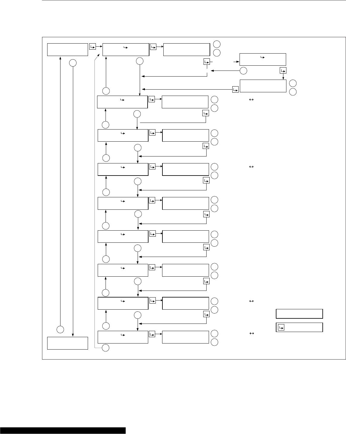
status field displays relevant cruise control icons and the set speed. If the vehicle is equipped with a
01/30/2012
SETUP
INFORMATION
+
−
+
−
+
−
+
−
+
−
+
−
+
−
+
−
+
−
+
−
+
+
+
+
+
+
+
+
−
−
−
−
−
−
−
−
−
+
PUSH KEY TO
Note: If parking brake is released while in stationary screens,
the display will return to the bar graph screen.
* = Indicates flashing text
= My Info
Press to toggle between selections
Miles or Hours
Press to set service interval
Press to toggle On Off
Press to toggle On Off
Press to toggle On Off
Press to toggle Yes No
Press to increase target MPG
Press to decrease target MPG
Press to increase brightness
Press to decrease brightness
Press to toggle between selections
Press to toggle between selections
Off
SERVICE INTERVAL
PUSH KEY TO
CHANGE SERV MI
PUSH KEY TO
CHANGE TEMP WARN
PUSH KEY TO
CHANGE TARGET MPG
PUSH KEY TO
PUSH KEY TO
PUSH KEY TO
PUSH KEY TO
PUSH KEY TO
PUSH KEY TO
INTERVAL *2000 MILES
− LESS MORE +
TEMPERATURE WARNING
− OFF * ON +
LCD LAMP
− OFF * ON +
TARGET MPG *8.5
− LESS MORE +
CHANGE LCD LAMP
CHANGE BRIGHTNESS
CHANGE LANGUAGE
DISPLAY BRIGHTNESS
− DARK LIGHT +
LANGUAGE: *ENGLISH
FRENCH / SPNISH
CHANGE UNITS
CHANGE DRIVER SEL
RESET PARAMETERS
UNITS
*ENGLISH / METRIC
DRIVER SELECT
− OFF * ON +
RESET PARAMETERS
− *NO YES +
f544963a
OFF/*MILES/HOURS
CHANGE SERVICE
Vehicle Information
Screen
+
−
Fig. 4.18, ICU4M Setup Information Screens
Instruments
4.20
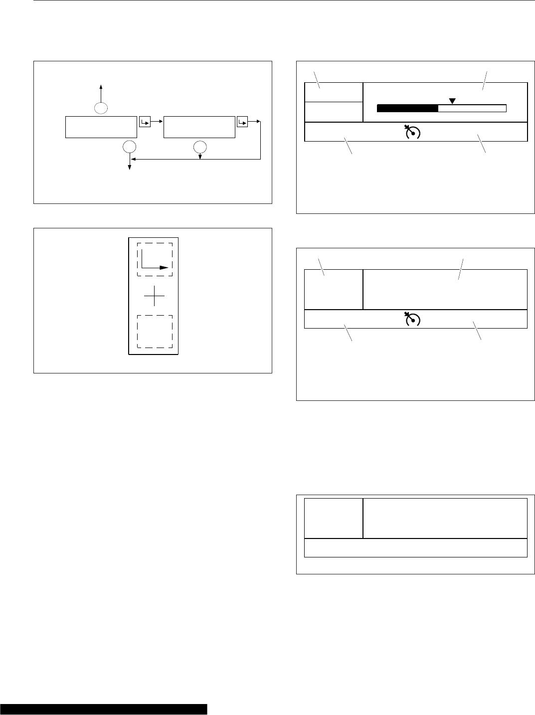
manual transmission, time and temperature are dis-
played in the top left corner of the driver message
center. The message field displays the driving
screens and alert messages. See Fig. 4.21.
If the vehicle is equipped with an automated trans-
mission, the gear display is located in the top left
corner of the driver message center. Time and tem-
perature are displayed in the message field, unless
an alert message is active or a driving screen has
been selected. The odometer and cruise control sta-
tus field are displayed along the bottom of the mes-
sage center. See Fig. 4.22. For information about
transmission display options, see Chapter 15.
Alert Messages
Alert messages are displayed in the message field to
notify the driver when certain conditions occur. They
include warnings, cautions, and other messages that
require the driver’s attention. Not all alert messages
are critical to the operation of the vehicle. More im-
portant messages take priority over less important
messages.
NOTE: All alert messages follow the format
shown in Fig. 4.23.
Press the +switch to acknowledge alert messages
and revert to the previously displayed driving screen.
+
−−
VEHICLE
INFORMA
TION
DASH
#
123
−
12345
−
123
SW VER
1
.
0
Setup Information
Outside
Air
T
emp
03/30/2010 f040803
Fig. 4.19, ICU4M Vehicle Information Screens
f61117304/03/2012
Menu
Back
Fig. 4.20, ICU4Me Control Switch
06/26/2012 f611166
5555555 mi
1/7
NW
77° F
Trip MPG: 5.6
015
5
12
3
4
10
65 mph
1. Temperature and Compass
2. Message Field
3. Cruise Control Status Field
4. Odometer
Fig. 4.21, Driver Message Center Without Gear Display,
ICU4Me
1/7
NW
77 °F
06/26/2012 f611165
10
A econ
5555555 mi
12
3
4
65 mph
1. Gear Display
2. Temperature and Compass
3. Cruise Control Status Field
4. Odometer
Fig. 4.22, Driver Message Center with Gear Display,
ICU4Me
Park Brake On!
06/12/2012 f611192
10
A econ
5555555 mi
Fig. 4.23, Parking Brake Alert Message
Instruments
4.21
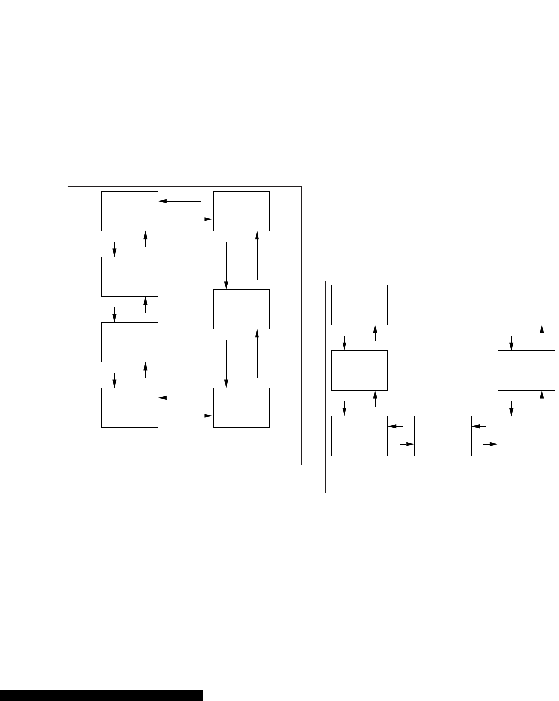
The following alert messages will repeat intermittently
until the condition is eliminated:
•turn signal on
•low voltage
•no datalink
•low transmission air pressure (Detroit transmis-
sions only)
Driving Screens
With the parking brake off, only the driving screens
are available. Use the +and –switches on the steer-
ing wheel to scroll through the driving screens; see
Fig. 4.24. To reset any values, press and hold the +
switch.
•Temperature
•MPG information
•Trip information
•Leg information
•Gauge display (if selected)
•Predictive Cruise Control (optional)
•Enter parked menus
Parked Screens/Menus
Park the vehicle and set the parking brake to access
the parked menus and submenus. See Fig. 4.25.To
reset values in any of the menus, press and hold the
+switch.
•Trip information
•Fuel information
•Engine information
•Diagnostics
•Service information
•Settings
•ICU Information
A small numerical fraction is displayed in the upper
right-hand corner of each screen to indicate the num-
ber of available screens or options to scroll through.
See Fig. 4.26. Press the upper half of the ICU4Me
control switch to select a menu choice. Press the
lower half of the control switch to back out of a se-
lected menu or submenu. Use the +switch to scroll
up, and the –switch to scroll down.
Time &
Temperature
MPG
Information
+
−
−
Trip
Information
Enter to
Stationary
Menu
−
+
Gauge
Display
Screens
Leg
Information
Predictive
Cruise
Control (opt)
+
+
−
+
−
+
−
06/21/2012 f040823
−
+
(if selected)
Use the +and –switches on the steering wheel to
navigate through the driving screens.
Fig. 4.24, Driving Screen Navigation, ICU4Me
+
−
−
+
−
+
−
+
+
−
−
+
06/26/2012 f040824
Trip Info
Fuel Info
Engine Info Diagnostics Service
Settings
ICU Info
Use the +and –switches on the steering wheel to
navigate through the parked menus.
Fig. 4.25, Parked Menus, ICU4Me
Instruments
4.22
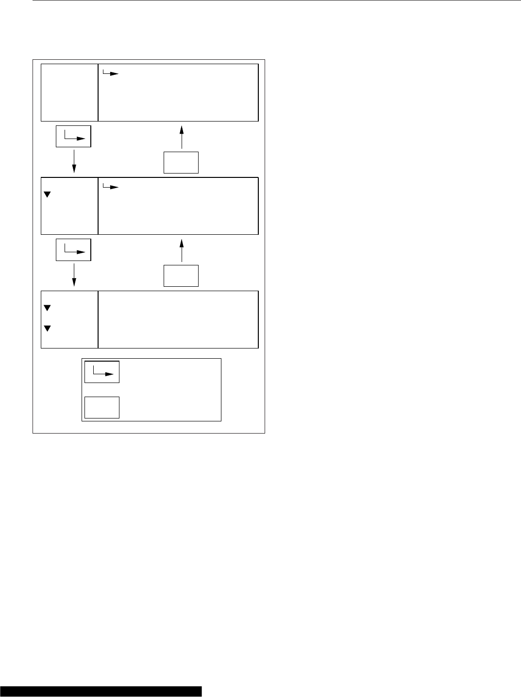
When navigating the parked menus, the left side of
the driver message center displays a "breadcrumb
menu" to show the order of menus and submenus
that have been selected during the current naviga-
tion.
Trip Information
The ICU can record data for one trip segment and
one leg segment. When trip information is reset, all
the leg information is reset as well.
Fuel Information
Using this menu, the driver can view the total fuel
used since the last reset, the total idle gallons used
since the last reset, and the average MPG since the
last reset.
Engine Information
Using this menu, the driver can view engine miles,
engine hours, gallons used, PTO hours, and PTO
gallons. Engine oil level is optional for Detroit en-
gines. The information contained in the Engine Infor-
mation screens cannot be reset.
Diagnostics
Active and historical faults are displayed in the diag-
nostics menu. See Fig. 4.27. If there are any active
faults, the total number of faults is displayed in pa-
renthesis next to the affected controller. To view spe-
cific active faults, press the upper half of the ICU4Me
control switch on the dash. Press the upper half of
the ICU4Me control switch to toggle between the text
description and the failure code for each selected
fault.
Service Information
Using this menu, the driver can enable, disable, and
set service intervals for engine miles or engine
hours. After enabling service intervals, select interval
unit (miles or hours), and the interval duration.
Settings
The settings menu contains the controls for the fol-
lowing settings:
•Display (includes brightness, contrast, display
light, and night mode settings)
•Gauge select
•Language
•Self-test
•Temperature warning enable/disable
•Units
The Gauge Select submenu allows the driver to se-
lect certain gauge values for display in the message
field while driving. See Fig. 4.28. Use the +and –
switches on the steering wheel to scroll through the
list of available gauges, then press the upper half of
the ICU4Me control switch to select a desired gauge.
The ICU4Me control switch can also be used to un-
check boxes if necessary.
1/3
Miles:
Gallons:
Menu
MENU
BACK
Avg. MPG:
Trip Info
Trip
123456.7
123456.7
123.4
1/2
Trip
Leg
Menu
MENU
BACK
Trip Info
1/7
Trip Info
Fuel Info
Menu
Engine Info
MENU
BACK
Indicates when to press
the MENU BACK switch
Indicates when to press
the ENTER switch
06/21/2012 f611193
Fig. 4.26, Parked Menu Navigation, ICU4Me
Instruments
4.23
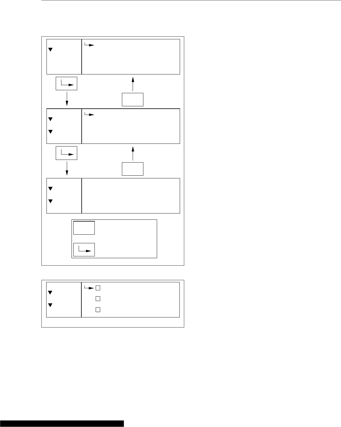
ICU Information
The ICU Information screen displays the part num-
bers for the instrument cluster and software.
Overhead Instrument Panel
The optional overhead instrument panel may hold a
citizen’s band (C/B) radio and any switches that can
not be accommodated on the driver’s or auxiliary
dash panels.
The underside of the overhead console also holds
the sun visors and the optional dome/reading light
asssembly. See Chapter 5 for more information on
the dome/reading light assembly.
1/3
Accelerator Pedal
Problem Detected
Diagnostics
MENU
BACK
Active
Engine (3)
1/3
ABS (1)
Engine (3)
MENU
BACK
1/2
Active (12)
Historic (0)
MENU
BACK
Indicates when to press
the MENU BACK switch
Indicates when to press
the ENTER switch
05/30/2012 f611194
Menu
Diagnostics
MSF (1)
Menu
Diagnostics
Active
Fig. 4.27, Diagnostics Menu Navigation, ICU4Me
06/26/2012 f611195
1/6
Axle Temp
Air Pressure
Engine Oil Temp
Menu
Settings
Gauge Disp. x
Fig. 4.28, Selecting Gauges to Display, ICU4Me
Instruments
4.24

5
Driver Controls
Ignition Switch and Key ............................................................ 5.1
Lighting Controls .................................................................. 5.2
Horn Controls .................................................................... 5.7
Powertrain Controls ............................................................... 5.7
Cruise Control ................................................................... 5.11
Dash-Mounted Brake Controls ...................................................... 5.14
Windshield Wiper/Washer Controls .................................................. 5.15
Suspension/Trailer Connection Controls .............................................. 5.16
Climate Controls ................................................................. 5.17
Seat Controls ................................................................... 5.19
Adjustable Steering Column Controls ................................................ 5.20
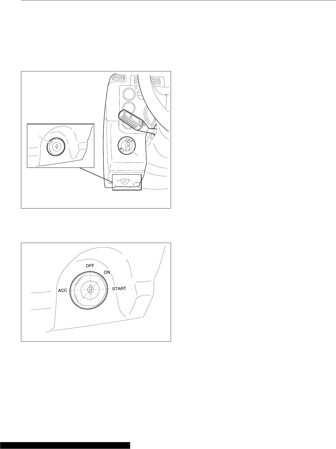
Ignition Switch and Key
The ignition switch is located on the left-hand dash,
below the headlight switch. See Fig. 5.1.
The ignition switch has four positions: OFF, ACC (ac-
cessory), ON, and START. See Fig. 5.2.
In the OFF position, the ignition switch is vertical.
The key can be inserted and removed only in the
OFF position.
The following functions are operable when the igni-
tion switch is in the OFF position (regardless of
whether the key is inserted):
•low-beam headlights
•taillights
•brake lights
•road lights
•dome lights
•clearance lights
•hazard warning lights
•utility lights
•baggage compartment lights
•spotlights
•electric horn
•clock
•refrigerator
•CB radio
•power mirrors
•power receptacle
•fuel heater
•electric oil pan heater
•electric or diesel-fired engine coolant pre-
heater
Turn the key counterclockwise to reach the ACC po-
sition. In addition to all the functions that are oper-
able in the OFF position, the following functions are
operable when the switch is in the ACC position:
•radio/stereo system
•heater and A/C fan
•mirror defog
•windshield fan
•ether start system
•air dryer
•backup lights
Turn the key clockwise past the OFF position to
reach the ON position. With the switch in the ON po-
sition, all electrical systems become operable and
04/30/2007
1
f610916
2
1. Headlight Switch 2. Ignition Switch
Fig. 5.1, Left-Hand Dash
07/19/2006 f610805
Fig. 5.2, Ignition Switch
Driver Controls
5.1

the warning and indicator lamps illuminate. Wait for
three seconds before starting the engine.
The SAM Cab vehicle controller automatically cycles
all exterior lights off and then on when the head-
lamps are on and the park brake is released, or set.
This rapid flash of the exterior lights is a self-test to
detect any bulb that is not operational. Drivers may
notice all lights flash simultaneously during this pro-
cess. This is the normal operating sequence. A fault
code is set for any bulb that is out.
IMPORTANT: Do not crank the engine until the
ICU self-check is complete.
Turn the key clockwise past the ON position to reach
the START position to start the engine. Release the
key the moment the engine starts. Do not operate
the starter longer than thirty seconds, then allow the
starter to cool between attempts. If the starter over-
heats, the starter protection system will prevent op-
eration of the starter until it has cooled. Release the
key the moment the engine starts.
The ignition key also locks and unlocks the cab
doors, the baggage door(s) and if equipped, the bunk
door(s).
Lighting Controls
IMPORTANT: Unless otherwise noted below,
press the upper half of the switch to activate the
desired light(s). Press the lower half of the
switch to turn the light(s) off.
Exterior Lighting Controls
Exterior light controls are listed here in alphabetical
order. See Fig. 5.3 for exterior light locations.
Auxiliary High Beam Lights
Auxiliary high-beam lights may be located in the front
bumper. To activate the auxiliary high beam lights,
press the upper part of the dash switch. The auxiliary
high beam lights will illuminate only when the high-
beam headlights are on. They will switch off tempo-
rarily when the low-beam headlights are on, until the
high beams are on again. Press the lower half of the
switch to deactivate it. See Fig. 5.4.
Backup Lights
Backup lights activate only when the vehicle is in re-
verse, and are designed to be used while backing up
at night.
Daytime Running Lights
The daytime running lights (DRL), if equipped, are
automatically activated when the ignition is switched
on and the parking brake is released. The DRL turn
off when the engine falls below 400 rpm, the parking
brake is applied, or the headlights are turned on.
Daytime running lights are mandatory for vehicles
domiciled in Canada. Vehicles domiciled in any other
location may have an optional override switch
(Fig. 5.4, ref. 2). This is a momentary switch that en-
ables the driver to deactivate the DRL. Press the
upper half of the switch briefly to activate or deacti-
vate the DRL.
Fog Lights
Fog lights are designed to reduce glare in foggy con-
ditions. The low-beam headlights must be on in order
to turn the fog lights on. Pull the headlight switch out-
ward to activate the fog lights.
Hazard Warning Lights
The hazard warning light switch is located on the
dash in what is referred to as the master module.
See Fig. 5.5. The hazard lights can be activated re-
gardless of the ignition switch position.
To activate the hazard lights, press the center of the
switch once. The switch will blink at the same rate
that the hazard lights flash. Press the switch again to
turn them off. All the turn signals on the vehicle and
trailer, as well as the turn signal indicators in the
ICU, flash simultaneously when the hazard lights are
activated.
Headlights
The headlight switch is a rotary switch located to the
left of the steering column, above the ignition switch.
See Fig. 5.6.
If the Follow Me Home feature is activated, the low-
beam headlights will remain on for nine seconds
after the vehicle is parked, if the headlights were on
prior to engine shutdown. This feature provides tem-
porary lighting in the path of the headlights while
walking to a building or other destination. If a vehicle
Driver Controls
5.2
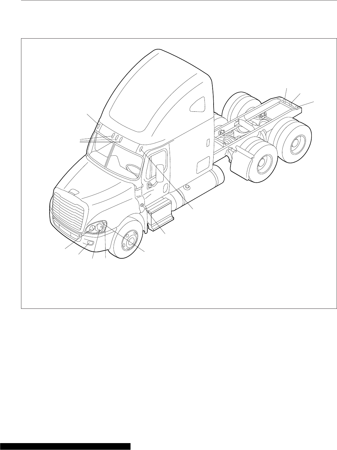
door is opened or closed while this feature is active,
the timer will add an additional 10 seconds of light-
ing. This feature can be temporarily disabled by turn-
ing the ignition switch on, or by cycling the headlight
switch from the off position to one of the other two
positions.
High-Beam Headlights
To activate the high-beam headlights, press the turn
signal lever forward towards the windshield while the
low-beam headlights are on. Return the turn-signal
lever back to its neutral position to deactivate the
high beams, and return to low beam headlights.
When the high-beam headlights are on, a blue light
illuminates on the instrument cluster. For vehicles
with fog lights, switching on the high beams will
switch off the fog lights. The headlight low beams
remain on continuously during high-beam operation.
02/03/2012 f544971
1
234
6
7
7
8
8
9
10
5
1. High-Beam Headlight
2. Fog Light, or Auxiliary High-Beam Light
3. Low-Beam Headlight
4. Marker Light
5. Turn Signal
6. Side Turn Signal and Marker Light
7. Clearance Light
8. Stop Light, Taillight, and Turn Signal
9. Back-Up Light
10. Identification Light
Fig. 5.3, Exterior Lights
Driver Controls
5.3
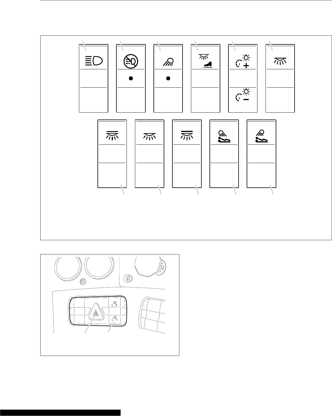
NOTE: The ignition switch must be on for the
high beams to work.
Marker Lights
Turn the headlight switch clockwise to past the off
position. See Fig. 5.6.
Marker Interrupt
The marker interrupt switch, located in the right-hand
switch pod of the steering wheel, temporarily flashes
the marker lights. See Fig. 5.7.
AUX
HIGH
DRL
OVRD
UTLY
LAMP
FOOT
WELL DOME
DOME REAR
DOME
REAR
DOME
LWR
LAMP
LWR
LAMP
01/05/2012 f611155
1 2 3 4 5 6
7 8 9 10 11
1. Auxiliary High Beam Light Switch
2. DRL Override Switch
3. Utility Light Switch
4. Cab Foot Well Light Switch
5. Panel Lights Switch
6. Rear Cab Dome Light Switch
7. Rear Cab Dome Light Switch
(mounted in sleeper)
8. Sleeper Rear Dome Light Switch,
Driver Side
9. Sleeper Rear Dome Light Switch,
Passenger Side
10. Sleeper Reading Light Switch,
Driver Side
11. Sleeper Reading Light Switch,
Passenger Side
Fig. 5.4, Dash-Mounted and Sleeper-Control Light Switches
03/20/2007 1f610855
2
1. Hazard Warning
Switch
2. Panel Lights Dimmer
Switch
Fig. 5.5, Master Module
Driver Controls
5.4
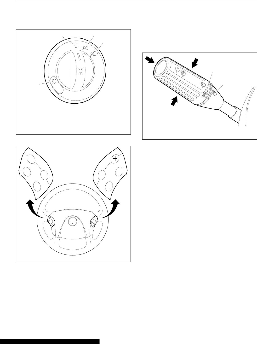
Spotlight
The spotlight switch is located on the pivoting handle
of the spotlight. There may be a single spotlight as-
sembly mounted above the driver’s door, or one
above each door.
Turn Signals
The turn-signal lever is on the left side of the steer-
ing column. See Fig. 5.8.
NOTE: The optional self-canceling turn signal
lever will automatically return to the neutral posi-
tion when the steering wheel returns to the
straight-ahead position after a turn.
Move the turn signal lever downward to turn the left-
turn signal on; move it upward to turn the right-turn
signal on. To manually cancel the signal, move the
lever to the neutral position.
When a turn signal is activated, a green indicator
light flashes on the instrument cluster.
Turn-Tip Feature
The turn-tip feature is advantageous in lane change
situations when the steering wheel does not travel far
enough to cancel a conventional turn signal request.
Pushing the turn-signal lever halfway to the normal
turning position to activate the turn-tip feature. The
signal will flash for a few seconds, then cancel. Acti-
vation of the turn-tip feature is immediately canceled
when a request for the turn signal in the opposite
direction is made.
Utility Lights
Utility lights can be swivel-mounted on upper half of
the cab, mounted on the exhaust support, or flush-
mounted on the back of the cab or sleeper. Press the
upper half of the switch to activate it. Press the lower
f610806
01/05/2012
1
23
4
1. Fog Lights (optional)—Activate by pulling the switch
out when the marker lights or headlights are on.
2. Off
3. Marker Lights
4. Headlights
Fig. 5.6, Headlight Switch
05/24/2007 f462049
ON/
OFF
ACC
RES CNCL
DEC/
SET
MRKR
INT
ENG
BRK
Fig. 5.7, Steering Wheel-Mounted Controls
07/19/2006 f820427
1
2
1. Wiper Control Dial 2. High-Beam Icon
Fig. 5.8, Multifunction Turn Signal Lever
Driver Controls
5.5
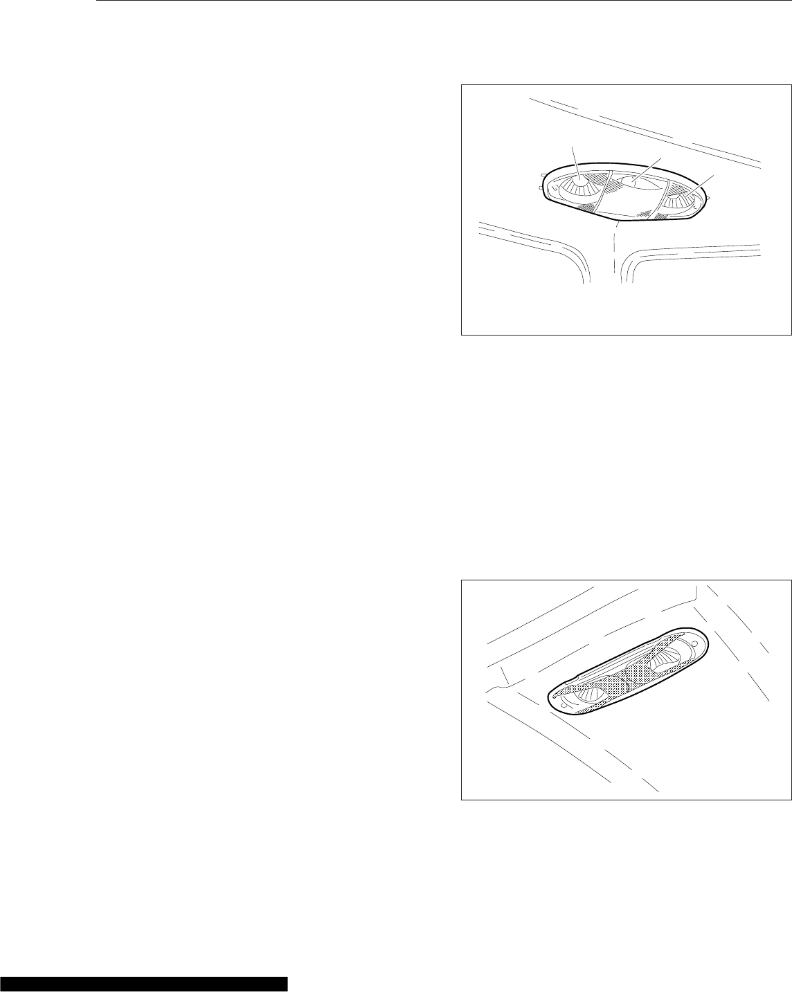
half of the switch to turn it off. When activated, a red
indicator light in the switch is illuminated. See
Fig. 5.4.
Interior Lighting Controls
Interior light controls are listed here in alphabetical
order.
The interior lights include panel lights, dome lights,
red map lights, clear reading lights, and courtesy
lights. Vehicles come pre-set from the factory with
theater lighting, which ramps up lights from low
power to full power when activated.
Sleepers have rear dome lights, bunk reading lights,
sleeper floor lights, and baggage compartment lights.
Baggage Compartment Lights
Baggage compartment lights are located on the un-
derside of the lower bunk, on both sides. Both lights
turn on when either baggage compartment door is
opened to illuminate the baggage compartment. The
lights also come on when the lower bunk is raised.
Foot Well Lights
When the driver or passenger doors are opened, red
lights illuminate both foot wells. These lights can also
be activated with the foot well light switch. See
Fig. 5.4. Press the upper half of the switch to turn
the foot well lights on, press the lower half of the
switch to turn them off.
Overhead Console Lights
The overhead console includes a clear reading light,
a clear dome light, and a red map light. See Fig. 5.9.
The dome lights illuminate when a door opens, then
stay on for a short time after both doors are closed.
Press the lens of the reading light, dome light, or
map light to activate each one independently of the
others.
Panel Lights
The panel lights illuminate when the headlights are
turned on. To adjust the brightness of the panel
lights, use the panel lights switch, usually located in
the master module next to the hazard flasher switch.
See Fig. 5.4. The panel lights brighten and dim in
5% increments, depending on whether the upper half
or the lower half of the switch is pressed. When the
headlights are turned on, the panel lights setting will
default to the intensity that was last set.
Rear Dome Light
A rear cab dome light is located on the roof, between
the bunk and the cab on sleeper vehicles. See
Fig. 5.10. The rear cab dome light will activate with
the dome lights when a door is opened, then stay on
for a short time after both doors are closed.
Use the dash-mounted switch or the switch in the
sleeper panel to activate the rear cab dome light.
See Fig. 5.4.
11/21/2006 f544907
1
2
3
1. Clear Reading Lamp
2. Clear Dome Lamp
3. Red Map Lamp
Fig. 5.9, Overhead Console Lights
11/21/2006 f544908
Fig. 5.10, Rear Cab Dome Light
Driver Controls
5.6
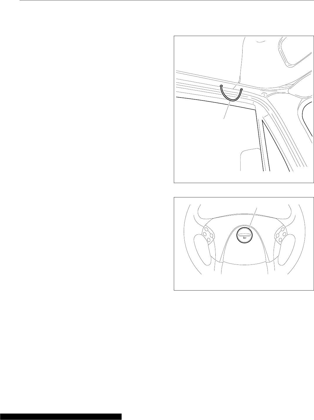
Sleeper Dome Light
Two dome lights are mounted on the sleeper roof,
close to the outside walls.
There are two switches in the sleeper that control the
sleeper dome lights. The passenger-side switch will
activate both dome lights. The driver-side switch op-
erates the driver-side light only. Press the upper half
of the switch to turn the sleeper dome light on, press
the lower half of the switch to turn it off.
Sleeper Foot Well Lights
The sleeper foot well switch is located in the lower
switch module in the sleeper. It looks identical to the
cab foot well switch. See Fig. 5.4. When the switch
is activated, two lights illuminate the sleeper floor.
Sleeper Reading Lights
Clear reading lights are mounted above the lower
bunk in the rear corners of the sleeper. There are
two switches in the sleeper control panel for the
reading lights. To turn a reading light on, press the
upper half of the switch. Press the lower half of the
switch to turn it off. See Fig. 5.4.
The reading lights can also be activated by pressing
the lens.
Horn Controls
Air Horn
Air horn(s) may be mounted on the roof of day cabs,
or under the driver-side floor for sleeper cabs. The
air horn is controlled by a wire lanyard that hangs
down inboard by the driver’s door. See Fig. 5.11.
Pull downward on the lanyard to sound the air horn.
Electric Horn
The button for the electric horn on a vehicle without
an airbag is located in the center of the steering
wheel. See Fig. 5.12. To sound the horn, press down
on the button.
The electric horn on a vehicle with an airbag is acti-
vated by pressing down on the top of the steering
wheel center pad. See Fig. 5.13.
The horn will sound for the duration that the button is
pressed, up to 60 seconds. The electric horn will op-
erate regardless of the position of the ignition key.
Powertrain Controls
Aftertreatment System Regen
Switches
NOTE: See Chapter 12 for detailed information
about the operation of the regeneration (regen)
switches and the aftertreatment system (ATS).
06/13/2007 f602322
1
1. Lanyard
Fig. 5.11, Air Horn Control
02/05/2007
1
f544961
1. Horn Button
Fig. 5.12, Steering Wheel, No Airbag
Driver Controls
5.7
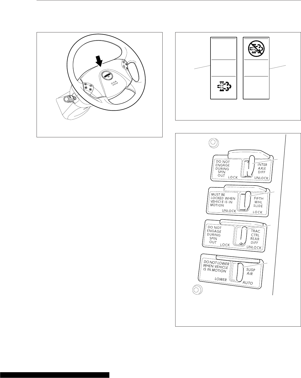
IMPORTANT: Depending upon local jurisdic-
tional emissions guidelines, vehicles that are
domiciled outside of the U.S. and Canada may
not have engines and/or emissions aftertreat-
ment systems that are compliant with EPA07,
EPA10, or GHG14 regulations.
The regen request switch, located on the dash, is
used to initiate a parked regen. See Fig. 5.14.To
access the regen request switch, lift the guard and
press the yellow button.
Some vehicles may be equipped with a regen inhibit
switch. See Fig. 5.14. To stop a regen in progress or
prevent the start of a regen, press the lower half of
the switch. Regen will be delayed until the switch is
no longer active.
Axle Switches
Some vehicles are equipped with an interaxle differ-
ential lock switch and/or a switch for each driver-
controlled differential lock (DCDL). See Fig. 5.15. For
more information about differential locks and using
them for traction control, see Chapter 16.
Engine Brake Switch
The Hi/Med/Lo engine brake 3-position switch con-
trols the amount of engine braking. See Fig. 5.16.
Press the lower third of the switch for low, center for
medium, and upper third for high.
01/13/2012 f462236
Press down on the top of the steering wheel center pad
to activate the horn.
Fig. 5.13, Steering Wheel With Airbag
f61115702/08/2012
NO
RGEN
1
2
1. Regen Request
Switch
2. Regen Inhibit Switch
Fig. 5.14, Regen Request and Inhibit Switches
1
2
3
4
01/05/2012 f611158
1. Interaxle Differential Lock Switch
2. Fifth Wheel Slide Switch
3. Driver-Controlled Differential Lock (DCDL) Switch
4. Air Suspension Dump Control Switch
Fig. 5.15, Axle and Suspension Switches
Driver Controls
5.8
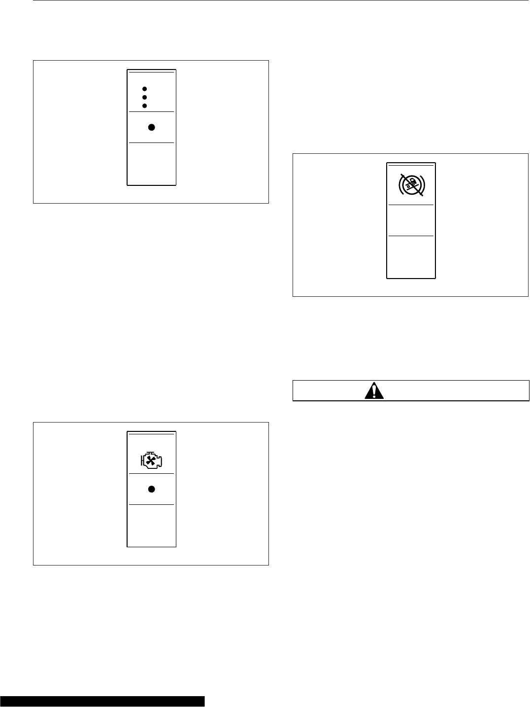
There is also an engine brake switch located in the
right-hand switch pod on the steering wheel. See
Fig. 5.7. Press the ENG BRK switch once to engage
or disengage the engine brake. Refer to Chapter 13
for instructions on using the engine brake.
Engine Fan Switch
The engine cooling fan can be turned on by the en-
gine fan switch.
To turn the engine fan on, press the upper half of the
switch. The fan will continue to operate for a set
amount of time and then turn off unless the coolant
temperature is high enough to continue fan opera-
tion. To turn the fan off before the set time period
ends, press the lower half of the switch. See
Fig. 5.17.
Hill Start Aid Override Switch
Some vehicles are equipped with a Hill Start Aid
(HSA) feature to prevent the vehicle from rolling
while on steep grades and to allow for a controlled
launch. HSA is "on" by default. It can be turned off
by pressing and releasing the HSA override switch
on the dash (see Fig. 5.18).
PTO Switch
To activate the PTO function, press the upper half of
the switch. Press the lower half of the switch to de-
activate the PTO function. See Fig. 5.19.
WARNING
To avoid injury, do not install a PTO that is not
Detroit Diesel approved onto a Detroit™Trans-
mission. Use of a non-Detroit Diesel approved
PTO with a Detroit Transmission could result in
unintended operation which could lead to severe
personal injury.
Transmission Controls
Detroit™Automated Transmissions
NOTE: See Chapter 15 for complete Detroit
automated transmission operating instructions.
Vehicles with Detroit transmissions use the multifunc-
tion control shown in Fig. 5.20. This control moves in
two directions and has two switches. It is used to
request manual shifts, change shift mode, set engine
brake levels, and control specialty engine brake func-
tions during cruise control operation.
ENG
BRK
f61090505/02/2007
HI
LO
Fig. 5.16, Engine Brake Switch
ENG
FAN
f61089902/26/2007
Fig. 5.17, Engine Fan Switch
HSA
OVRD
f61118604/30/2012
Fig. 5.18, Hill Start Aid Override Switch
Driver Controls
5.9
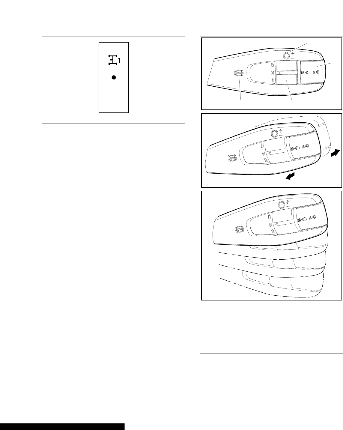
Eaton Automated Transmissions
NOTE: See Chapter 15 for complete automated
transmission operating instructions.
The SmartShift electronic transmission control is in-
stalled with the Eaton® Fuller® UltraShift™and
Eaton Fuller AutoShift™transmissions. The Smart-
Shift control is operated by the fingers of the driver’s
right hand, allowing both hands to remain on the
steering wheel.
A two-position driving mode slide switch is mounted
on the body of the control lever just before the
paddle widens out. The slide switch allows the driver
to choose automatic (AUTO) or manual (MAN) mode.
See Fig. 5.21.
Manual Transmissions
NOTE: See Chapter 14 for complete manual
transmission operating instructions.
If so equipped, the transmission range control and
splitter valves are attached to the gear shift knob.
The range-preselection lever allows the selection of
the low or high range for each transmission ratio. It is
used once during an upshift sequence and once dur-
ing a downshift sequence.
Dependent on the transmission model, some ratios
can be split using the splitter-control button.
Allison Automatic Transmissions
Automatic transmissions have up to six forward
speeds and one reverse speed. These transmissions
have electronic shift controls that can be pro- grammed to allow the use of different geared
speeds. See Fig. 5.22.
f61089402/23/2007
PTO
Fig. 5.19, PTO Switch
B
2
3
1
( + )
( − )
4
05/30/2012 f270163a
A
C
A. Front View
B. Shift Requests
C. Four positions for engine brake settings
1. Engine Brake Symbol
2. D/N/R Switch
3. Mode Switch
4. Gear Shift Symbol
Fig. 5.20, Detroit Multifunction Control
Driver Controls
5.10
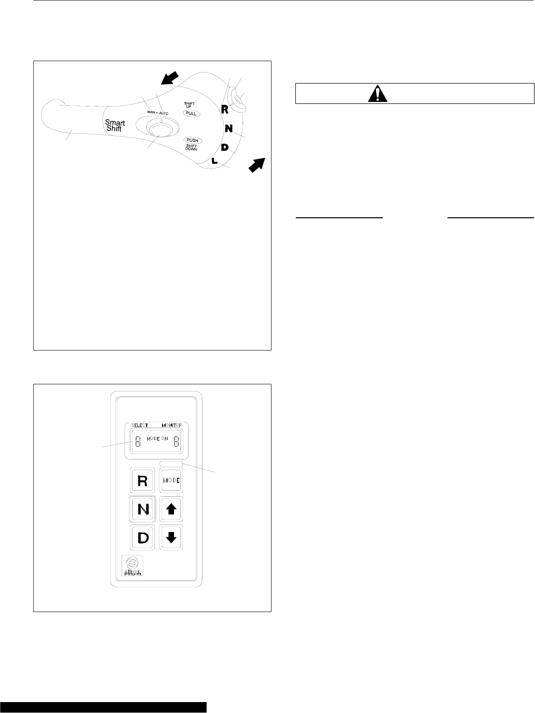
Cruise Control
WARNING
Do not use the cruise control system when driv-
ing conditions do not permit maintaining a con-
stant speed, such as in heavy traffic or on roads
that are winding, icy, snow-covered, slippery, or
roads with a loose driving surface. Failure to fol-
low this precaution could cause a collision or
loss of vehicle control, possibly resulting in per-
sonal injury or property damage.
NOTICE
When the cruise control is engaged, do not at-
tempt to shift gears without using the clutch
pedal. Failure to follow this precaution will result
in a temporarily uncontrolled increase in engine
speed. Transmission damage and gear stripping
could result.
IMPORTANT: On vehicles equipped with
VORAD Collision Warning System with Smart-
Cruise, see Chapter 6 before operating the
cruise control.
NOTE: If the vehicle is equipped with a Detroit
multifunction control, setting the cruise control
with the engine brake on will activate Descent
Control Mode. Moving the lever to the top posi-
tion will resume the set cruise speed. Moving
the lever down to engage the engine brake after
the cruise control has been set will activate De-
celeration Mode. See "Descent Control and De-
celeration Modes, Detroit™Automated Transmis-
sions" in this chapter.
The cruise control is operated by four buttons
mounted in the left-hand button pod of the steering
wheel. See Fig. 5.7.
•ON/OFF Button—Press to turn cruise control
on or off. When cruise control is on, a green
telltale illuminates in the ICU. The speed
memory will be retained until the cruise control
is disabled with the ON/OFF button, or the igni-
tion is turned off.
01/24/2003
12
34
56
8
9
10
11 12
f270120
7
To upshift manually, pull the lever back (towards the
driver). To downshift manually, push the lever forward
(away from the driver).
1. SmartShift Control Lever
2. Slide Switch (forward driving mode switch)
3. MAN Mode (of slide switch)
4. AUTO Mode (of slide switch)
5. Upshift Direction
6. Reverse Position (of selector switch)
7. Selector Switch
8. Neutral Lock Button
9. Neutral Position (of selector switch)
10. Drive Position (of selector switch)
11. Low Position (of selector switch)
12. Downshift Direction
Fig. 5.21, SmartShift Control (Eaton Fuller UltraShift
and AutoShift transmissions)
10/31/94 f600369a
1
2
1. Indicator Panel 2. Mode ID
Fig. 5.22, Allison Push-Button Shift Selector
Driver Controls
5.11
•DEC/SET Button—Press to set the cruise
speed while the vehicle is traveling at the de-
sired speed. Press and hold to decrease the
set cruise speed.
•CNCL Button—Press to pause the cruise con-
trol, while retaining the speed setting in
memory. The cruise control can also be disen-
gaged, while retaining the speed memory, by
depressing the brake or clutch pedals.
•ACC/RES Button—Press to resume the set
speed. Press and hold to accelerate the set
cruise speed.
1. To cruise at a particular speed:
1.1 Press the ON/OFF button to turn cruise
control on.
1.2 Depress the accelerator pedal until the
speedometer reaches the desired speed.
NOTE: Cruise control is cancelled if the
brake or clutch pedal is depressed, or ve-
hicle speed drops below the minimum cruise
control speed.
1.3 Press the DEC/SET button to set the de-
sired speed.
NOTE: The speed memory is lost whenever the
ignition switch is turned to OFF, or cruise control
is turned off.
2. To disengage the cruise control, do one of the
following:
•Press the CNCL button.
•Depress the brake pedal.
•Depress the clutch pedal (on a manual
transmission only).
3. To resume a preselected cruise speed:
3.1 Ensure cruise control is on.
3.2 Press the ACC/RES button. Cruise will
return to the last set speed.
NOTE: If vehicle speed drops below the
minimum cruise control speed, cruise control
will disengage. To resume to the preselected
cruise speed, increase vehicle speed to
above minimum cruise control speed and
press the ACC/RES button.
4. To increase cruise speed, press the ACC/RES
button until the vehicle accelerates to the desired
speed.
5. To decrease cruise speed, press the DEC/SET
button until the vehicle decelerates to the desired
speed.
Run Smart Predictive Cruise™
Predictive Cruise Control (PCC) is an optional fuel
savings application that adjusts vehicle speed predic-
tively, based on the approaching road. Using 3D digi-
tal map technology and GPS, PCC evaluates the up-
coming road grade about a mile in advance to
determine the most fuel-efficient vehicle speed. Ve-
hicles equipped with PCC have a sticker on the
dash. See Fig. 5.23.
The 3D digital map database contains profile infor-
mation for over 200,000 highway miles (322,000 km)
in the 48 contiguous United States. PCC will vary the
set cruise speed by up to 6% depending on the ap-
proaching road grade. If the engine brake is enabled,
PCC will automatically engage the engine brake
when actual vehicle speed exceeds the cruise set
speed by 6%. This is different from conventional
cruise control, which maintains the speed set by the
driver.
WARNING
Apply the brakes and downshift as necessary
when driving on downhill grades. PCC does not
adequately control vehicle speed on steep down-
hill grades. Failure to use normal braking tech-
niques when PCC is active could result in per-
sonal injury and vehicle damage.
IMPORTANT: PCC adjusts the vehicle set speed
to achieve maximum fuel economy, but it does
04/15/2009 f100149
Fig. 5.23, Run Smart Predictive Cruise Control Sticker
Driver Controls
5.12
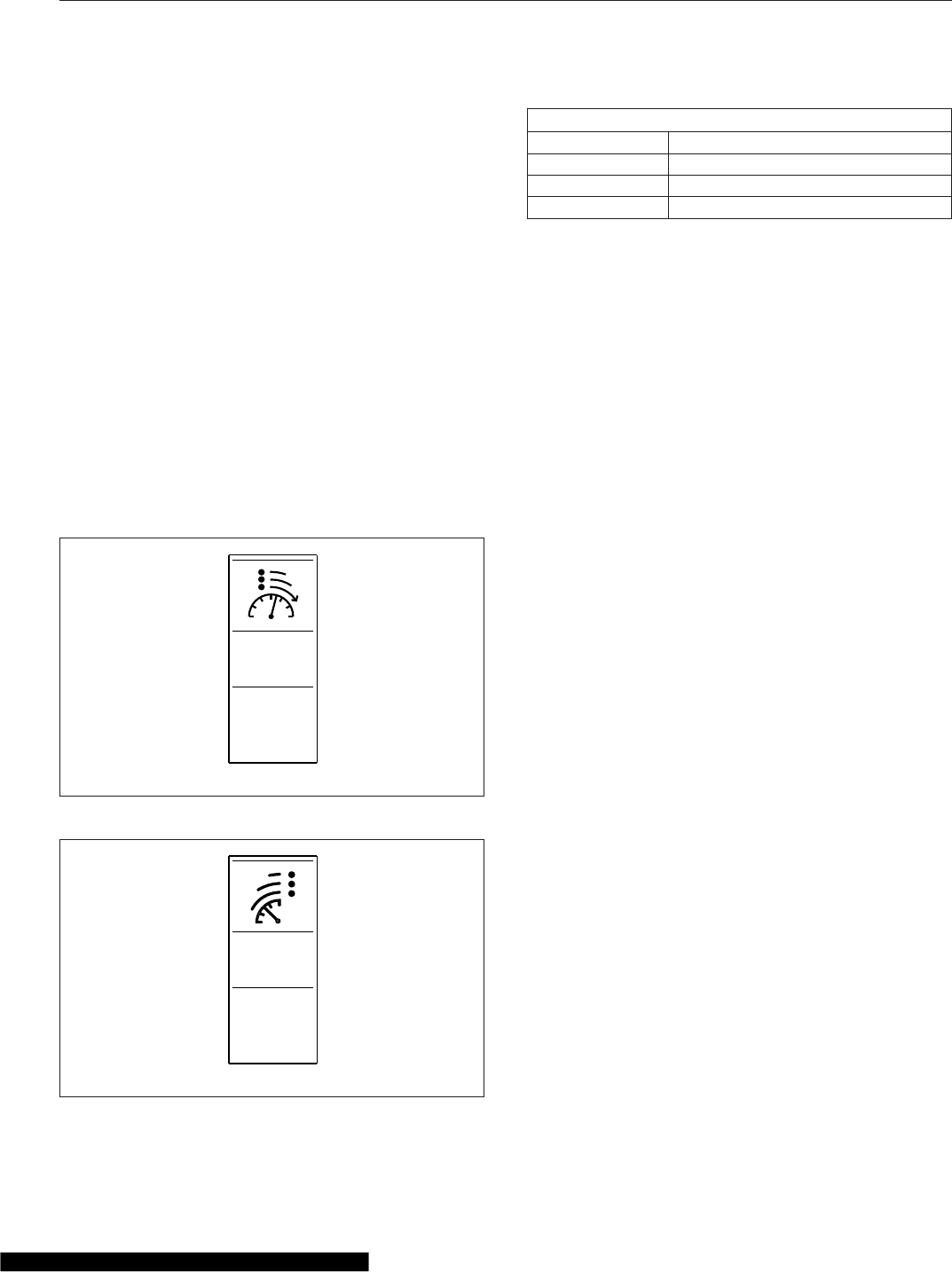
not account for traffic flows or surrounding ve-
hicles.
Driver interaction with PCC is the same as conven-
tional cruise control, using the standard cruise control
buttons. In the event of a problem with PCC, or when
driving on a road with no profile information avail-
able, the system reverts to conventional cruise
control.
Cruise Control ("CC") Limiter
On vehicles equipped with a CC Limiter (or CC
Band) switch (see Fig. 5.24 or Fig. 5.25), the cruise
control limiter allows the vehicle to exceed the set
cruise control speed before engine braking is ap-
plied. The CC limiter switch provides more flexibility
to the existing cruise control limit function, allowing
the driver to tune the cruise function to better suit
driving preferences and conditions. To select a limit,
use the three-position CC Limiter switch on the dash.
See Table 5.1 for switch settings.
CC Limiter Switch Settings
Position Approximate Overrun Setting
Topin 3mph(5km/h)
Middle 6 mph (9 km/h)
Bottom in Unlimited
Table 5.1, CC Limiter Switch Settings
Descent Control and Deceleration
Modes, Detroit™Automated
Transmissions
On vehicles equipped with a Detroit multifunction
control (Fig. 5.26), the functions of the lever posi-
tions for engine brake control change when cruise
control is set. Two distinct modes can be activated:
•Descent Control Mode—engine braking keeps
the speed below cruise set speed; throttle is
not automatically applied.
•Deceleration Mode—engine braking activates
to reduce vehicle speed (with no lower limit) at
a constant rate.
Descent Control Mode
Descent Control Mode keeps the vehicle speed
below the set cruise speed on a downhill.
To activate Descent Control Mode, set the cruise
control speed with the engine brake on (Fig. 5.26,
positions 1, 2, or 3). In this mode, all three levels of
engine braking will be employed to to keep the
speed below the set cruise speed. This mode will not
keep the speed above the lower limit of the set
speed, so it is possible to eventually coast to a stop,
unless the lever is moved to "engine brake off" (posi-
tion 0), or throttle is applied. After throttle application,
the Descent Control Mode is resumed.
Moving the lever to "engine brake off" (position 0)
cancels Descent Control Mode and resumes cruise
speed. To reactivate Descent Control Mode, reset the
cruise control speed with the lever in position 1, 2, or
3.
Deceleration Mode
Deceleration Mode reduces the vehicle speed at a
constant rate.
With the cruise control speed set, activate Decelera-
tion Mode by moving the lever to engine brake on
CC
LIMIT
f61120302/19/2013
Fig. 5.24, CC Limiter Switch
CC
BAND
f61119105/08/2012
Fig. 5.25, CC Band Switch
Driver Controls
5.13
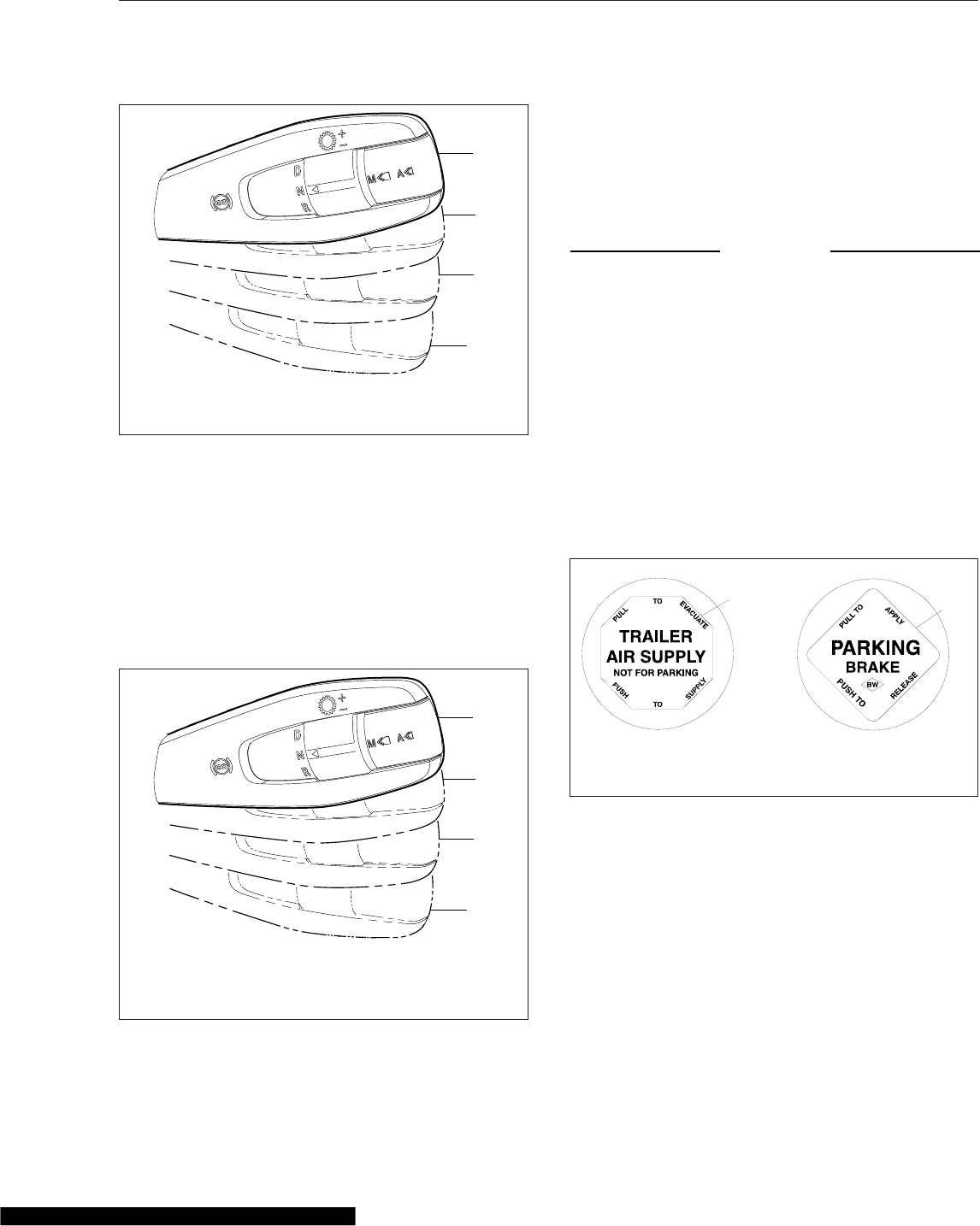
(Fig. 5.27, position 1, 2, or 3). This mode engages
one of the engine brake levels, depending on the
lever position. The vehicle will decelerate at a con-
stant rate until the vehicle comes to a stop, unless
throttle applied to override the deceleration, or the
lever is moved to "engine brake off" (position 0).
Moving the lever to position 0 resumes the previously
set cruise control speed.
Dash-Mounted Brake Controls
NOTE: See Chapter 13 for detailed information
about brake systems.
Parking Brake Control Valve
NOTICE
Do not step on the service brake pedal while the
parking brakes are applied. To do so can cause
damage to the brake mechanisms.
The yellow diamond-shaped knob operates the park-
ing brake valve. See Fig. 5.28. Pull the knob out to
apply both the tractor and the trailer spring parking
brakes. Push the knob in to release the tractor spring
parking brakes. Before the spring parking brakes can
be released, the air pressure in either air brake sys-
tem must be at least 65 psi (447 kPa).
If the trailer is not equipped with spring parking
brakes, pull the parking brake valve out to apply the
tractor parking brakes and the trailer service brakes.
Trailer Air Supply Valve
The red octagonal-shaped knob operates the trailer
air supply valve, which charges the trailer air supply
system and releases the trailer spring parking
brakes. See Fig. 5.28.
After the vehicle and its air hoses are connected to a
trailer and the pressure in the air system is at least
65 psi (447 kPa), push the trailer air supply valve
knob in (and leave it in) to charge the trailer air sup-
ply system and release the trailer spring parking
brakes. Pull the trailer air supply valve out before
0
1
2
3
02/19/2013 f270164a
0. Resume cruise control set speed.
1, 2, 3. Descent Control maintains set speed.
Fig. 5.26, Descent Control Mode Positions, Detroit
Multifunction Control
0
1
2
3
02/19/2013 f270164a
0. Resume cruise control
set speed.
1. Low
2. Medium
3. High
Fig. 5.27, Deceleration Mode Positions, Detroit
Multifunction Control
f610291
1 2
03/10/99
1. Trailer Air Supply Valve (red knob)
2. Parking Brake Control Valve (yellow knob)
Fig. 5.28, Brake Valve Control Knobs
Driver Controls
5.14
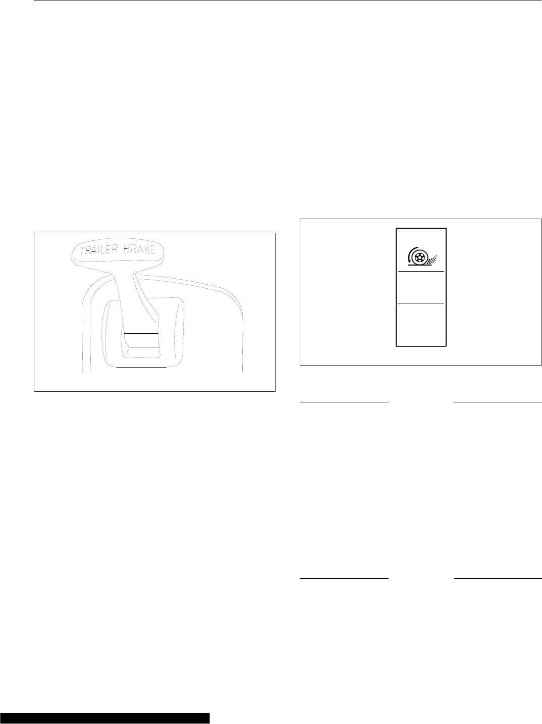
disconnecting a trailer or when operating a vehicle
without a trailer.
Trailer Brake Lever
The trailer brake lever is used to apply the trailer ser-
vice brakes without applying the truck or tractor ser-
vice brakes. It is usually mounted on the right-hand
control panel. See Fig. 5.29. The valve can be par-
tially or fully applied, but in any partially on position it
will be overridden by a full application of the service
brake pedal. Move the lever down to apply the trailer
brakes; move the lever up to release the trailer
brakes. The lever will automatically return to the up
position when it is released.
Antilock Braking System
The Meritor™WABCO® Antilock Braking System
(ABS) passively monitors vehicle wheel speed at all
times, and controls wheel speed during emergency
stops or wheel lock situations.
During emergency or reduced-traction stops, fully
depress the brake pedal until the vehicle comes to a
safe stop. Do not pump the brake pedal. With the
brake pedal fully depressed, the ABS will control all
wheels to provide steering control and a reduced
braking distance.
The ABS is designed to communicate with a trailer
ABS, if they are compatible. Compatibility will result
in the illumination of the trailer ABS lamp during ve-
hicle start-up and fault detection. The trailer ABS
lamp will not illuminate unless a compatible trailer is
connected to the tractor.
Vehicles with ABS may have Automatic Traction Con-
trol (ATC). On these vehicles, the ATC system auto-
matically limits wheel spin during reduced-traction
situations. In normal braking applications, the stan-
dard air brake system is in effect.
ATC includes a deep snow and mud option to in-
crease available traction on extra-soft surfaces like
snow, mud, or gravel. A switch labeled ATC will be
located on the dash. See Fig. 5.30. Press the switch
to temporarily allow more drive wheel spin. The acti-
vation of the deep snow and mud option is indicated
by a flashing WHEEL SPIN lamp. Press the switch
again to cycle the system back to normal operation.
NOTICE
The deep snow and mud option is intended to be
used under specific slippery conditions that re-
quire momentary increased wheel spin. Using
this option for an extended period of time may
damage the brake system.
Windshield Wiper/Washer
Controls
The multifunction turn signal lever is attached to the
left-hand side of the steering column, just below the
steering wheel. See Fig. 5.8.
NOTICE
Do not attempt to manually move the windshield
wiper arms. Wiper motor damage will occur if the
arms are forcibly moved.
10/17/2001 f610591
Fig. 5.29, Trailer Brake Lever
f61090706/15/2007
ATC
Fig. 5.30, ATC Switch
Driver Controls
5.15
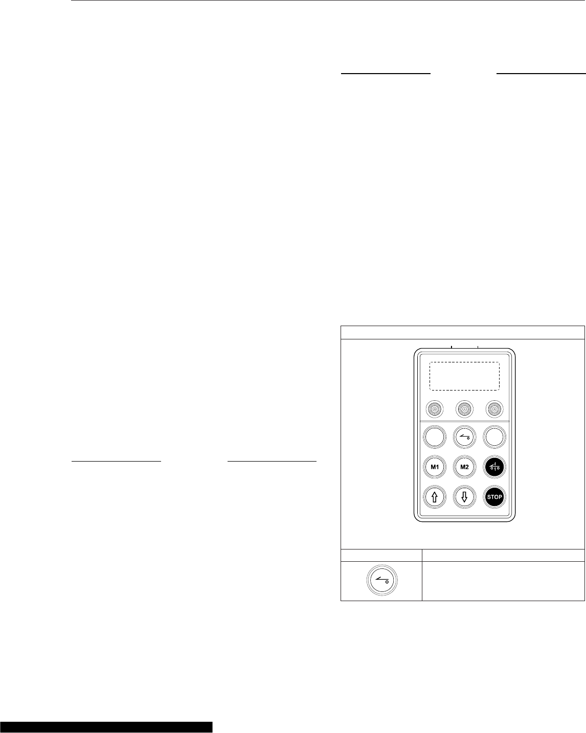
The wipers are operated by a rotary switch in the
wiper control dial, which is on the end of the turn sig-
nal lever. There are five intermittent settings, marked
on the dial by lines of increasing length, and two
steady speed settings: LO and HI.
Turn the wipers on by rotating the control dial coun-
terclockwise. Rotate the control dial further to in-
crease the speed of the wipers through the various
intermittent settings, then to LO and HI.
Rotate the control dial clockwise to slow the wipers
down. Rotate the control dial clockwise as far as it
will go to turn the wipers off.
The windshield washer button is located at the end
of the turn signal lever. Momentarily press the wind-
shield washer button to initiate a single wipe without
activating the washer pump. The wipers will swipe
one full cycle and return to the inactive position.
To operate the windshield washers, press and hold
the button in. After a short delay, the washer will
pump windshield washer fluid onto the windshield for
as long as the washer button is pressed. The wind-
shield wipers will turn on at low speed while the
washer button is pressed. After the button is re-
leased, the wipers will continue to operate for one to
several wipe cycles, depending on how long the
wash button was pressed initially.
Suspension/Trailer Connection
Controls
Air Suspension Dump Control Switch
NOTICE
Do not operate the vehicle over uneven ground
such as ramps, speed bumps, curbs, etc. with
the air springs deflated. Doing this may lead to
air bag separation from the piston, preventing the
suspension air springs from re-inflating.
The air suspension height control switch may be
used to aid in connecting or disconnecting from a
trailer. See Fig. 5.15. When the switch is set to
LOWER, the air-suspension dump valve deflates the
air springs to lower the rear of the vehicle. In the
AUTO position, the automatic ride-control valves op-
erate for normal driving.
NOTICE
Never exhaust air from the suspension while
driving. When the air is exhausted, the suspen-
sion will not absorb road shocks, and compo-
nents may be damaged.
A red LED in the switch is illuminated when the sus-
pension is deflated.
ECAS Remote Control Unit (ECAS
only)
Some vehicles equipped with Electronically Con-
trolled Air Suspension (ECAS) have a remote control
unit to lower and raise the rear suspension. See
Table 5.2 for keys and functions.
If the suspension is outside normal ride height
(amber lamp on), the ECAS system will automatically
return the suspension to normal ride height when
vehicle speed reaches or exceeds a set speed (usu-
ally set to 5 mph).
ECAS Remote Control Keys and Functions
08/16/2013 f611211
Key Function
Remote Control On/Off. The middle
light will remain lit while the remote is
active.
Driver Controls
5.16
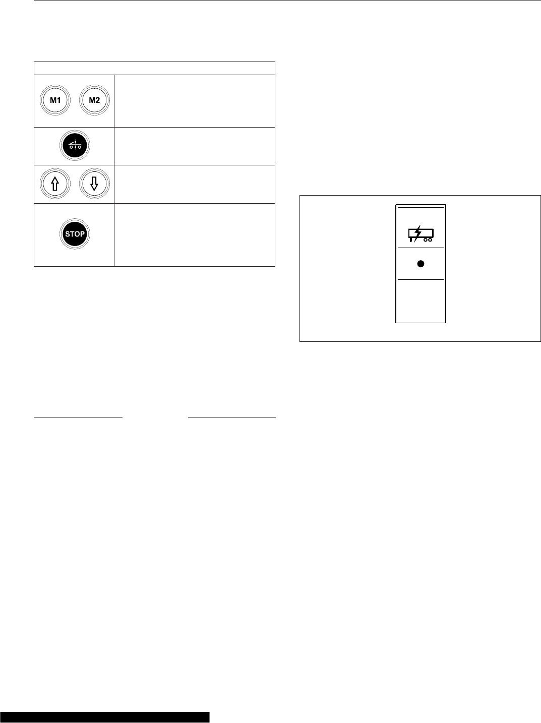
ECAS Remote Control Keys and Functions
Memory keys. Pressing the Stop key
and a memory key simultaneously will
store the current height. Once stored,
pressing the key will adjust the
vehicle to the stored height.
Normal height key. This key will
return the vehicle to normal ride
height.
Lift and lower keys. These keys will
raise or lower the rear suspension
height.
The Stop key. Pressing the Stop key
will interrupt and stop all adjustments
being made by the remote control.
When the key is off, holding the Stop
key for 2 seconds will cancel the 1
hour Standby mode.
Table 5.2, ECAS Remote Control Keys and Functions
ECAS Standby Mode
Once the key is turned off, the ECAS will enter
Standby Mode, remaining powered and adjusting to
level and load changes for 1 hour. To cancel Standby
mode, hold the STOP button on the remote for 2
seconds.
Fifth Wheel Slide Control Switch
NOTICE
Do not activate the fifth wheel slide control valve
while the vehicle is in motion. To do so could
cause damage to the fifth wheel member, the
kingpin, the cab or trailer, and ultimately to the
drivetrain.
The fifth wheel air slide valve allows repositioning of
the sliding fifth wheel from inside the cab. See
Fig. 5.15. Move the air slide control valve switch to
the LOCK position to lock the fifth wheel to the base-
plate. Move the switch to the UNLOCK position to
unlock the fifth wheel slide mechanism, allowing
changes to the total length of the tractor-trailer and
changes to axle loads to comply with state or provin-
cial laws.
For detailed operating instructions for fifth wheel
slide, refer to Chapter 18. A red indicator light illumi-
nates whenever the fifth wheel slide is unlocked.
Trailer Auxiliary Switch
Trailers that are equipped with pneumatic brakes and
used in North America or South America are gener-
ally equipped with power for the trailer lights. The
connection is passed from the vehicle to the trailer
via the primary receptacle, controlled by a dash
switch.
Press the top of the switch to activate the trailer aux-
iliary function. Press the bottom of the switch to turn
trailer auxiliary function off. See Fig. 5.31.
Climate Controls
NOTE: See Chapter 8 for detailed climate con-
trol panel operating instructions.
Cab Climate Control
The climate control panel allows you to control the
heating, ventilating, defrosting, and air conditioning
(A/C) functions. The cab climate control panel has
three switches to control the functions of the cab
temperature system; see Fig. 5.32:
•fan switch with recirculation button
•temperature control switch with A/C button
•air selection switch (with bunk-override button
on sleeper cab only)
The fan switch controls the fan speed, and forces
fresh or recirculated air through the air outlets. To
increase airflow, turn the switch clockwise to a higher
number. To decrease airflow, turn the switch counter-
clockwise to a lower number.
TRLR
AUX
f610888
02/23/2007
Fig. 5.31, Trailer Auxiliary Switch
Driver Controls
5.17
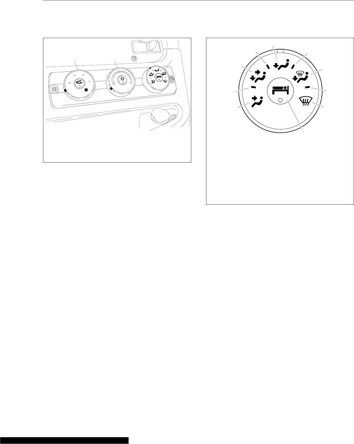
Recirculation mode limits the amount of outside air
that enters the cab. Press the recirculation button to
prevent dusty or smoky air from entering the cab.
NOTE: To prevent the buildup of odors and/or
oxygen depletion inside the cab, the system
switches from full recirculation mode to partial
recirculation mode after 20 minutes.
The temperature control switch is used to select the
desired temperature. Turn the switch clockwise to the
red area for warm air. Turn the switch counterclock-
wise to the blue area for cool air.
The A/C cools and dehumidifies the air inside the
cab. Press the A/C button, located in the center of
the temperature control switch, to turn the A/C on
and off.
The air selection switch allows the control of air flow
through the face outlets, the floor outlets, the defrost
(windshield) outlets, or a combination of these out-
lets. See Fig. 5.33.
Bunk-Override Button
The bunk-override button is located in the center of
the cab air-selection switch (sleeper-cabs only). See
Fig. 5.33.
Press the bunk-override button to make the cab con-
trols override the settings on the sleeper temperature
control panel; the sleeper temperature will mimic the
cab settings. An amber LED in the button is illumi-
nated when the bunk-override mode is activated.
When the override switch is not activated, the cab
climate control panel can be adjusted without affect-
ing the sleeper settings.
Sleeper Climate Control
The sleeper temperature can be controlled from the
sleeper climate control panel or from the cab climate
control panel if the bunk-override button is activated.
The fan switch controls the sleeper temperature fan
speed. To increase airflow, turn the switch clockwise
to a higher number. To decrease the airflow, turn the
switch counterclockwise to a lower number. See
Fig. 5.34.
The temperature control switch is used to select the
desired temperature in the sleeper. Turn the switch
clockwise to the red area for warm air. Turn the
switch counterclockwise to the blue area for cool air.
Press the button in the center of the temperature
control switch to activate the A/C.
0
24
8
6
07/20/2006 f831701
12 3
1. Fan Switch with Recirculation Button
2. Temperature Control Switch with Air Conditioning
Button
3. Air Selection Switch with Bunk-Override Button
Fig. 5.32, Cab Climate Control Panel
06/08/2007 f610948
1
2
3
4
5
6
7
8
9
10
1. Face Mode
2. Selection Between Face Mode and Bi-Level Mode
3. Bi-Level Mode
4. Selection Between Bi-Level Mode and Floor Mode
5. Floor Mode
6. Selection Between Floor Mode and Defog Mode
7. Defog Mode
8. Selection Between Defog Mode and Defrost Mode
9. Defrost Mode
10. Bunk-Override Button (on sleeper-cabs only)
Fig. 5.33, Air Selection Switch With Bunk-Override
Button
Driver Controls
5.18
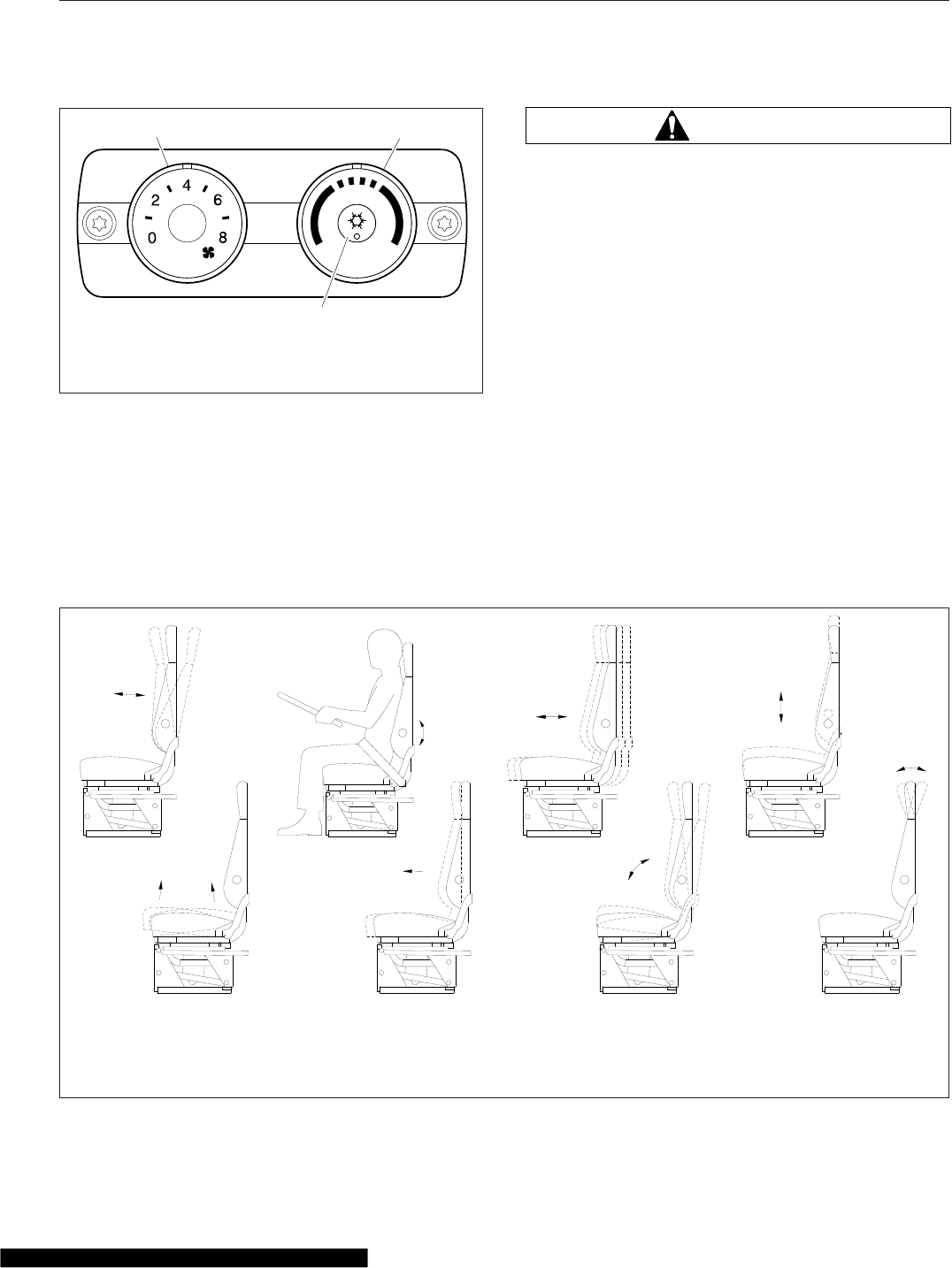
Cancel bunk-override mode, if activated, by changing
the sleeper fan speed or temperature setting. The
system will then operate from the sleeper controls.
Seat Controls
NOTE: See Chapter 7 for detailed information
about seat controls and adjustments.
WARNING
Keep hands, tools, and other objects away from
the scissor points under the seats. Failure to do
so could cause personal injury.
The following is a description of adjustments that can
be made to various seats. Not all seats have all of
the adjustments listed below. See Fig. 5.35.
•Backrest tilt
•Lumbar support
•Isolator
•Height adjustment
•Bottom cushion angle (fore-and-aft bottom
cushion height)
•Fore-and-aft seat slide (seat track adjustment)
•Seat tilt
•Headrest adjustment
06/08/2007 f610949
12
3
1. Fan Switch
2. Temperature Control
3. Air Conditioning
Button
Fig. 5.34, Sleeper Climate Control Panel
10/26/2000 f910149a
1
2
34
567
8
1. Backrest Tilt
2. Lumbar Support
3. Isolator Feature
4. Height Adjustment
5. Bottom Cushion Angle (fore-and-
aft cushion height)
6. Fore-and-Aft Seat Slide (seat
track adjustment)
7. Seat Tilt
8. Upper Backrest Adjustment
Fig. 5.35, General Seat Adjustments
Driver Controls
5.19
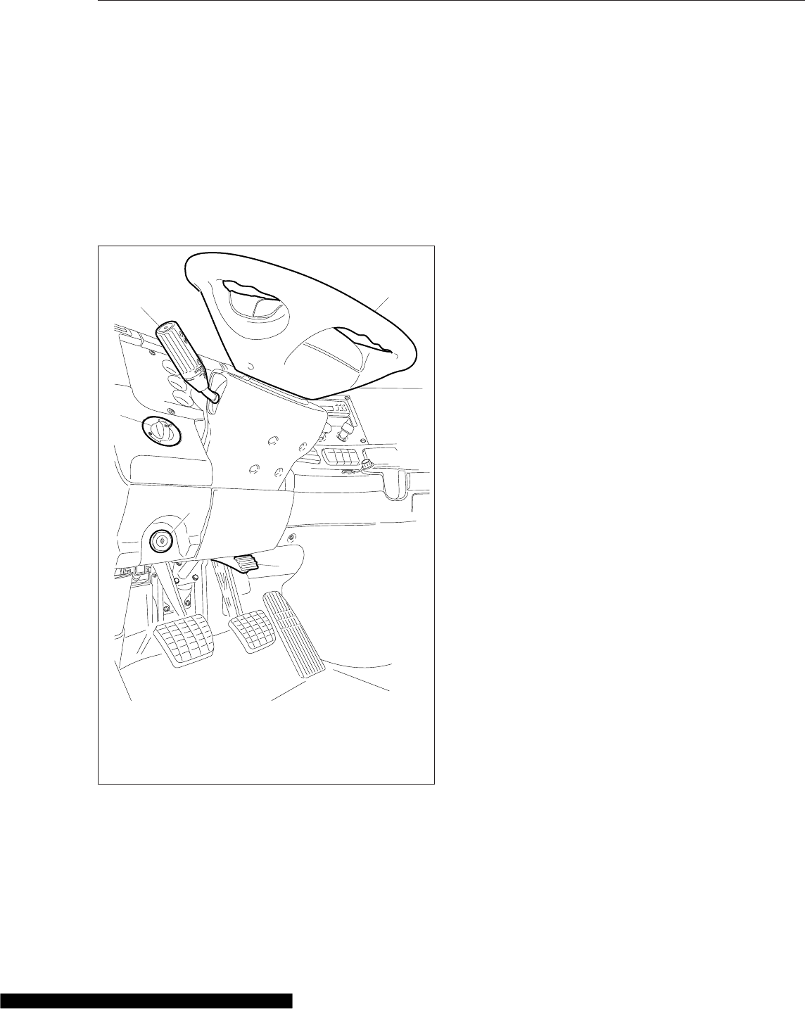
Adjustable Steering Column
Controls
To adjust the steering column, depress the foot pedal
located below the steering column. See Fig. 5.36. Tilt
the steering column to the desired angle. Telescope
the steering column closer or further away by push-
ing or pulling it. Release the foot pedal to lock the
steering column in place.
07/19/2006 f610799
1
2
3
4
5
1. Multifunction Turn
Signal Switch
2. Headlight Switch
3. Ignition Switch
4. Tilt Steering Column
Lever
5. Steering Wheel
Fig. 5.36, Steering Column and Left Panel Controls
Driver Controls
5.20

6
Driver Assistance Features
VORAD VS-400 System ........................................................... 6.1
OnGuard™Collision Safety System ................................................... 6.7
Lane Departure Warning Controls ................................................... 6.10
Roll Stability System .............................................................. 6.11
Enhanced Stability Control ......................................................... 6.13
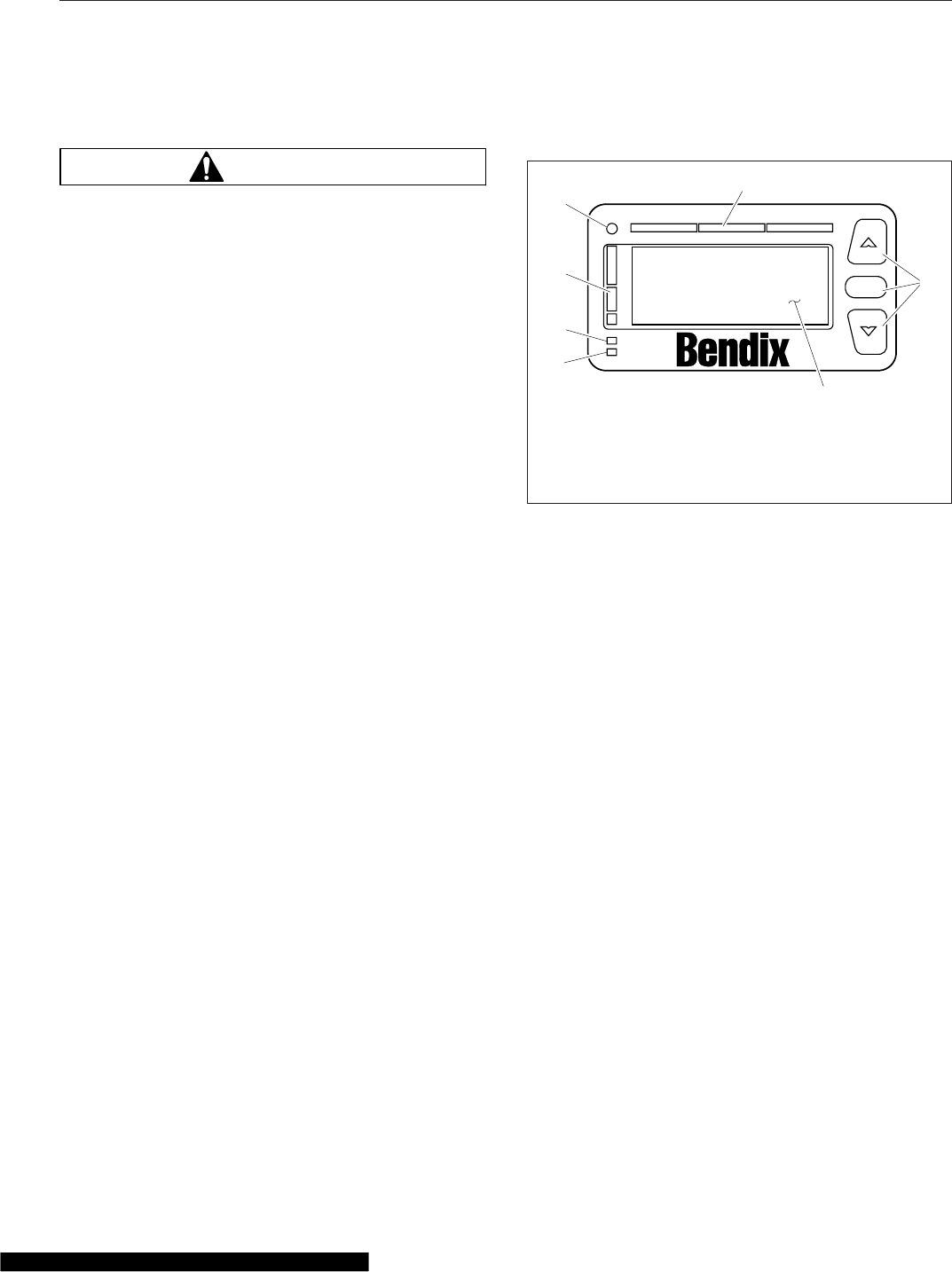
VORAD VS-400 System
WARNING
The VORAD VS-400 System is intended solely as
an aid for an alert and conscientious professional
driver. It is not intended to be relied upon to op-
erate a vehicle. Use the system in conjunction
with rearview mirrors and other instruments to
safely operate the vehicle. Operate a vehicle
equipped with the VS-400 System in the same
safe manner as if the CWS were not present.
The VS-400 System is not a substitute for safe,
normal driving procedures, nor will it compen-
sate for any driver impairment such as drugs,
alcohol, or fatigue.
The VS-400 System may provide little or no warn-
ing of hazards such as pedestrians, animals, on-
coming vehicles, or cross traffic.
Failure to drive safely and use the system prop-
erly could result in personal injury and/or death
and severe property damage.
The VORAD VS-400 system is an on-board radar
system that monitors traffic conditions, warning the
driver of potentially hazardous driving situations.
The collision warning system (CWS) tracks objects
ahead of the vehicle, warning the driver with visual
and audible indicators whenever following distances
become unsafe.
SmartCruise® adjusts the vehicle’s cruise speed in
order to match the speed of traffic ahead, allowing
the driver to maintain a safe following distance while
cruise control is engaged.
The optional side object detection system warns of
unsafe lane changes by detecting vehicles that may
be difficult to see in adjacent lanes.
The VORAD VS-400 system performs in fog, rain,
snow, dust, smoke, and darkness. The VS-400 sys-
tem becomes active whenever the ignition key is
switched to ON.
Driver Interface Unit
The driver interface unit (DIU) provides visual and
audible alerts, along with system status information.
The DIU also provides an interface for changing sys-
tem settings. Menu selections are made by pressing
the up and down arrow buttons, and the OK button.
See Fig. 6.1.
The following warning and indicator lights illuminate
on the DIU:
•Red: illuminates with the collision alert
•Yellow: illuminates with 3-, 2-, and 1-second
following distance alerts
•Orange: illuminates when a system failure oc-
curs
•Blue: illuminates when information is available
Immediately after the ignition switch is turned to ON,
the DIU initializes a self-test routine. During the ini-
tialization, the VORAD screen displays and all lamps
illuminate for approximately three seconds, along
with a power-up tone. When the initialization is com-
plete, the DIU displays the VS-400 system configura-
tion screen. See Fig. 6.2.
Menu Selections
IMPORTANT: The display of a menu item is
overridden whenever conditions require an alert
or collision warning to be displayed.
After initialization, the menu screen is displayed.
Scroll to the desired menu item by pressing an arrow
button, then press the OK button to select the item.
See Fig. 6.3. If the driver does not make a selection
within 30 seconds, or the vehicle begins to move, the
DIU reverts to the system status display.
TM
f610919a
1
2
3
4
5
6
7
OK
02/03/2012
1. Fault Indicator
2. Info Indicator
3. Following Distance
Lights
4. Ambient Light Sensor
5. Collision Alert Lights
6. User Interface Keypad
7. Graphic Display
Fig. 6.1, Driver Interface Unit (DIU)
Driver Assistance Features
6.1
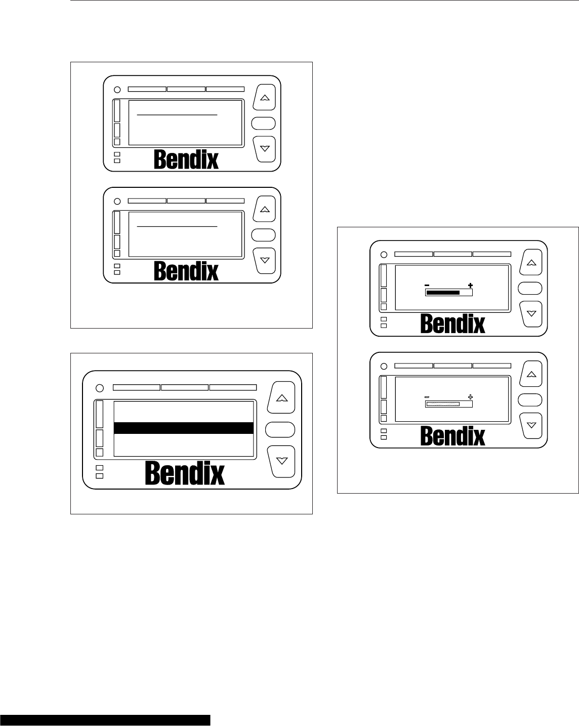
The display of any menu item is overridden when-
ever conditions require an alert or collision warning
to be displayed.
Demo (vehicle must be stationary)
When the vehicle is stationary and Demo mode is
selected, the DIU will demonstrate the meaning of all
LED and screen displays, including alert messages
and sound warnings. Scroll through the demo
screens by pressing the down arrow. Pressing any
other key exits Demo mode.
Volume
The minimum adjustable volume is 50% of the maxi-
mum volume. If the DIU volume is not adjustable, the
display screen shows a grayed bar graph whenever
volume adjustment is selected. See Fig. 6.4. After
each ignition switch cycle, the volume will default
back to 100%.
NOTE: Headway and collision alert tones may
be suppressed when the brake is applied if the
system is configured to do so.
SmartCruise Headway Range
Headway range adjustment is only available with
SmartCruise. Headway range is adjustable between
3.25 and 2.25 seconds. The headway range setting
will default to 3.25 seconds after each ignition power
cycle.
If headway range adjustment is disabled, only the
3.25 sec screen is displayed. See Fig. 6.5 for the
various headway range screens. Press the OK but-
ton to exit the menu.
VORAD started
Collision Warn
SmartCruise
f610921a
VORAD started
Collision Warn
A
B
OK
OK
02/03/2012
TM
TM
A. Configured for CWS only
B. Configured for CWS and SmartCruise
Fig. 6.2, System Configuration Screens
f610922a
System Status
Volume
Demo
02/03/2012
OK
TM
Fig. 6.3, Menu Screen
f610925a
A
B
Volume
Volume
OK
OK
02/03/2012
TM
TM
A. Adjustable Volume
B. Non-Adjustable Volume
Fig. 6.4, Volume Screen
Driver Assistance Features
6.2
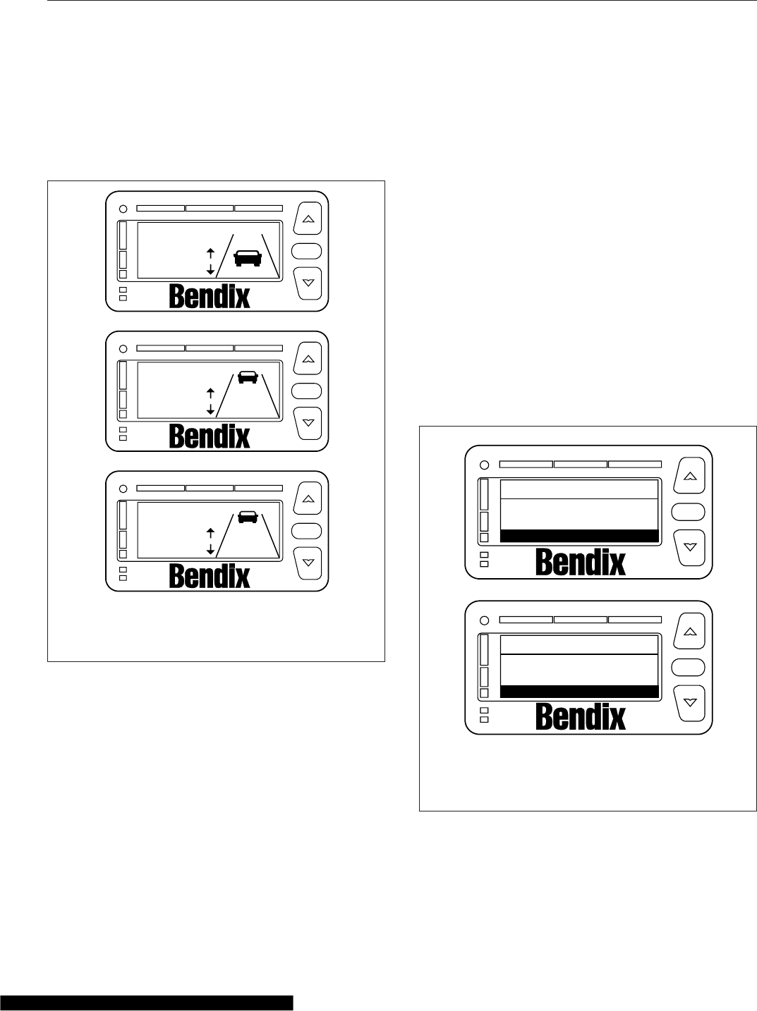
NOTE: If the headway range is adjusted to
three seconds or below and SmartCruise is ac-
tive, the 3-second collision warning headway
alert will not display. All other alerts are not
suppressed.
Brightness
Use the up and down arrows to change the DIU
backlight and warning LED brightness. Press the OK
button to exit the brightness screen.
The ambient light sensor reading determines if the
DIU is in daytime or nighttime mode. Menu-adjusted
brightness is applied only to the mode the DIU is in
at the time of adjustment. The previous brightness
settings are repeated after each ignition cycle. How-
ever, the graphic display and the warning LED bright-
ness range are constrained such that they are al-
ways visible regardless of how low the brightness is
adjusted in all driving conditions. Press the OK but-
ton to exit the menu.
Unit Adjustment Screen
The unit adjustment screen allows the driver to select
either km/h or mph units for display of SmartCruise
set speed. Press OK to exit the mph selection
screen.
System Status
System status shows the status of each system, indi-
cating if the system is operating normally. If a system
is not operating normally, the system displays Failed
beside the system name. Failed indicates that a fault
is preventing the system from operating and it cannot
be used until the fault is corrected or acknowledged.
Depending on the VS-400 system installed, one of
the screens shown in Fig. 6.6 will appear unless a
system fault is active. Press OK to exit the system
status menu.
Diagnostics
The DIU displays fault codes currently active when
this screen is selected and the vehicle is stationary.
f610927a
C
3.25 sec
SmartCruise
Range
A
SmartCruise
Range
2.25 sec
B
3.25 sec
SmartCruise
Range
fixed
OK
OK
OK
02/03/2012
TM
TM
TM
A. Minimum headway adjustment
B. Maximum headway adjustment
C. Headway range disabled
Fig. 6.5, Headway Range Screen
f610923a
A
B
Collision warn
SmartCruise
VORAD
status
OK
OK
Press OK for Menu
Collision warn
VORAD
status
OK
Press OK for Menu
OK
OK
02/03/2012
TM
TM
A. Status display for CWS and SmartCruise
configuration
B. Status display for CWS configuration
Fig. 6.6, System Status Screens
Driver Assistance Features
6.3
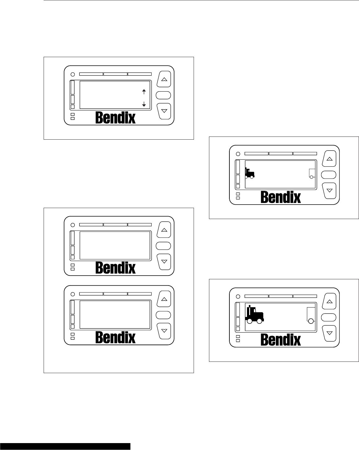
See Fig. 6.7. Contact an authorized Freightliner ser-
vice center if fault codes display.
Collision Warning System
The CWS may require a warm-up period of up to
one minute if the outside air temperature is below
32°F (0°C). The DIU will display a warm-up message
until the system reaches operating temperature. See
Fig. 6.8.
The alerts given by the VS-400 system are based on
the distance to the object ahead, whenever vehicle
speed is 10 mph (16 km/h) or faster. The VS-400
CWS identifies and tracks the nearest object in the
lane of travel. This object is classified by the range,
and assigned a message described under the follow-
ing headings.
Object Detected
When a vehicle is detected in the same lane of travel
within 350 ft (107 m) but farther than a 3-second fol-
lowing distance, the DIU will display OBJECT DE-
TECTED. See Fig. 6.9.
3-Second Headway Alert
When a vehicle is detected to be within a 3-second
following distance, a single yellow indicator will illumi-
nate and the DIU will display 3 seconds. See
Fig. 6.10.
f610929a
DIU DIAGNOSTICS
SPN: 00886 FMI:012
OK OK
02/03/2012
TM
Fig. 6.7, DIU Diagnostic Screen
f610924a
A
B
Do not use
Radar Warming Up
Radar Warming Up
SmartCruise
Please wait
OK
OK
02/03/2012
TM
TM
A. CWS with
SmartCruise
B. CWS Only
Fig. 6.8, CWS Warm-Up Screens
f610930a
Object Detected OK
02/03/2012
TM
Fig. 6.9, Object Detected Alert
f610931a
3 seconds OK
02/03/2012
TM
Fig. 6.10, 3-Second Alert
Driver Assistance Features
6.4
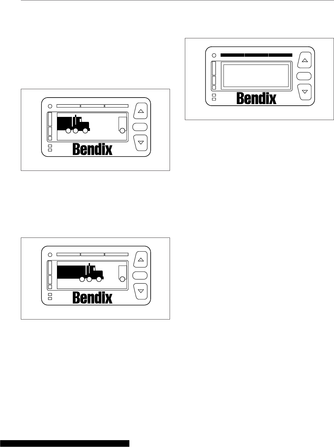
2-Second Headway Alert
When the following distance to the object ahead in
the same lane of travel decreases to within two sec-
onds, a second yellow indicator will illuminate, the
DIU will display 2 seconds, and a single tone will
sound. See Fig. 6.11.
1-Second Headway Alert
When the following distance to the object ahead in
the same lane of travel decreases to within one sec-
ond, a third yellow indicator will illuminate, the DIU
will display 1 sec, and two tones will sound. See
Fig. 6.12.
Collision Alert: ½-Second Headway
When the following distance to the object ahead in
the same lane of travel decreases to 0.5 second, the
red indicators all illuminate across of the DIU, the
DIU will display COLLISION ALERT, and a tone will
sound repeatedly. See Fig. 6.13.
SmartCruise
When approaching slower moving traffic with the ve-
hicle’s cruise control engaged, SmartCruise adapts
the engine cruise speed to that of the closest vehicle
ahead, allowing the vehicle to maintain a safe follow-
ing distance without disengaging the cruise control.
The DIU will display the SmartCruise status screen
indicating the vehicle’s current set cruise speed.
Once the speed of traffic ahead increases beyond
the adapted engine cruise speed, the original cruise
control set speed re-engages.
When SmartCruise is engaged, depressing the accel-
erator pedal will override the SmartCruise and will
cause the vehicle to accelerate. Depressing the
brake or clutch pedals will deactivate SmartCruise.
When approaching a slow moving or stopped vehicle
ahead, SmartCruise will attempt to maintain the mini-
mum following distance by reducing the engine
cruise speed and engaging the engine brake, if nec-
essary. If SmartCruise is unable to maintain the mini-
mum following distance, the driver will be alerted by
the CWS headway alerts until the driver takes control
or conditions clear.
Side Object Detection
The optional side object detection system may be
installed on one or both sides of the vehicle. The
radar sensor(s) are located on the side of the ve-
hicle, while the sensor display unit is mounted on the
A-pillar. See Fig. 6.14.
The side sensor display unit uses two lights to dis-
play the status of the side sensor(s). The yellow light
indicates the system is active, but no objects are de-
tected. The red light indicates that the side sensor
detects an object. If the vehicles turn signal is active
f610932a
seconds
2
OK
02/03/2012
TM
Fig. 6.11, 2-Second Alert
f610933a
sec
1
OK
02/03/2012
TM
Fig. 6.12, 1-Second Alert
f610934a
COLLISION
ALERT OK
02/03/2012
TM
Fig. 6.13, Collision Alert
Driver Assistance Features
6.5
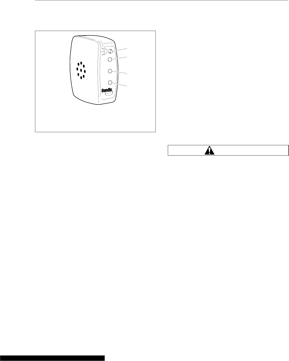
and the sensor detects an object alongside the ve-
hicle, an audible warning tone will sound.
Special Road Situations
Certain road situations may affect the system’s ability
to detect objects. These situations include the effects
of curves, dips, and hills which can provide an unex-
pected result.
NOTE: A warning may sound when an object is
detected in front of the vehicle even though the
driver intends to turn away or stop before reach-
ing the object.
•When an object is detected in a very sharp
right- or left-hand turn, the audible alarm will
not sound.
•When approaching a curve, alarms may sound
and lights illuminate, because of an object off
the road directly in line with your vehicle. This
will not occur when the brakes are applied.
•When approaching a roadway descending to a
lower elevation, elevated obstacles such as
overpasses and overhead signs may be de-
tected.
•Vehicles cannot be detected on the other side
of a hill. An alarm will not sound until the object
is within the antenna assembly’s field of view.
•On approaching a steep hill, objects above the
beam cannot be detected. Generally, the beam
hitting the road surface does not cause an
alarm.
•The side sensor only detects objects within its
field of view, next to the tractor. A vehicle be-
hind the field of view will not be detected.
•The side sensor range is set to detect
average-sized vehicles 2 to 10 feet (0.5 to 3
meters) away in the adjacent lane.
•The radar beam will detect near range cut-ins
of approximately 30 feet (9 meters) or less,
depending on the angle of entrance into the
lane in front of your vehicle.
•A continuous fixed object on the right side of
the vehicle such as a guard rail, wall, tunnel, or
bridge may cause the side sensor alert light to
stay on.
WARNING
Heavy rain or water spray at the side sensor may
cause both the yellow and red lights on the side
sensor display to illuminate at the same time.
Under these conditions the system is temporarily
unable to provide adequate warnings.
Failure to drive safely and use the system prop-
erly could result in personal injury and/or death
and severe property damage.
Maintenance
Keep the antenna and side sensor free of buildup of
mud, dirt, ice, or other debris that might reduce the
system’s range.
Failure Display Mode/Fault Codes
The VS-400 performs internal diagnostics at power-
up, then continuously monitors system components
thereafter.
If a failure is detected, depending on what features
are affected, the DIU displays a screen similar to
Fig. 6.15, blinks the orange fault light, and sounds a
tone. Press the OK button to acknowledge the fault.
After the fault has been acknowledged, the DIU will
attempt to return to normal operations. The orange
LED is continuously illuminated while the fault per-
sists. If the fault disappears, the VS-400 transmits a
f610935b
02/06/2012
1
4
3
2
1. Volume Adjust
2. Red LED–Object Detected
3. Ambient Light Sensor
4. Yellow–No Object Detected
Fig. 6.14, Side Sensor Display Unit
Driver Assistance Features
6.6
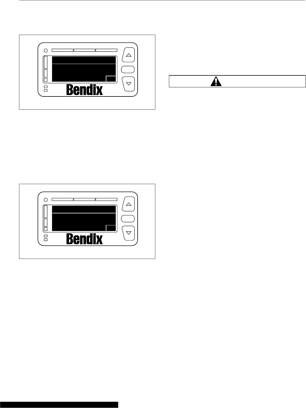
message to indicate that the fault status has
changed to a previously active fault.
In the event the CWS antenna becomes blocked
while the vehicle is moving (e.g., snow, mud, ice,
tampering, etc.), the system sounds a tone and dis-
plays the fault screen shown in Fig. 6.16.
Contact an authorized Freightliner dealer to review
and clear previously active fault codes.
OnGuard™Collision Safety
System
Meritor WABCO OnGuard is a forward-looking radar-
based adaptive cruise control and collision safety
system with active braking. The system includes a
collision warning system (CWS), adaptive cruise con-
trol (ACC) with active braking, and a collision mitiga-
tion system (CMS).
The system performs in fog, rain, snow, dust, smoke,
and darkness. To be detected, objects must be within
the radar field of view and provide a surface area
that can reflect the radar.
The front-looking antenna assembly transmits radar
signals to, and receives them back from, objects
ahead of the vehicle. This allows the determination of
the distance, speed, and angle of the object ahead.
The system uses this information to warn the driver
of potentially dangerous situations.
WARNING
The Meritor WABCO OnGuard™Collision Safety
System is intended solely as an aid for an alert
and conscientious professional driver. It is not
intended to be relied upon to operate a vehicle.
Use the system in conjunction with rearview mir-
rors and other instruments to safely operate the
vehicle. Operate a vehicle equipped with the On-
Guard in the same safe manner as if the CWS
were not present.
The OnGuard Collision Safety System is not a
substitute for safe, normal driving procedures,
nor will it compensate for any driver impairment
such as drugs, alcohol, or fatigue.
The OnGuard Collision Safety System may pro-
vide little or no warning of hazards such as pe-
destrians, animals, oncoming vehicles, or cross
traffic.
Failure to drive safely and use the system prop-
erly could result in personal injury and/or death
and severe property damage.
OnGuard Display Unit
The OnGuard system controls are located in the dis-
play unit. The display provides visual and audible
warnings and messages, as well as verification of
correct system operation and faults. Menu selections
are made by pressing the up and down arrows, and
the MODE button. See Fig. 6.17.
The display includes:
•an internal speaker
•a graphic display
•buttons to scroll and select options
Collision Warning System (CWS)
The CWS generates audible and visual alerts when
the vehicle’s following distance may result in a colli-
sion. The CWS provides only a warning, and will not
control vehicle speed.
f610936a
VORAD fault
Collision warn FAILED
OK
OK
02/03/2012
TM
Fig. 6.15, VORAD Fault Display
f610937a
VORAD fault
Radar Blocked
OK
OK
02/03/2012
TM
Fig. 6.16, Antenna Blocked Display
Driver Assistance Features
6.7
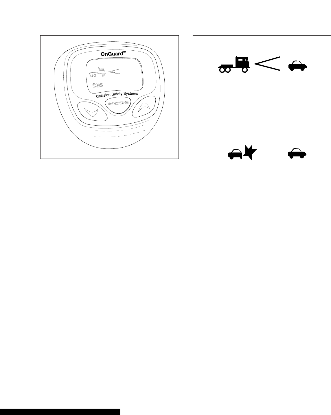
The CWS cannot be disengaged or turned off, and is
always active at vehicle speeds above 15 mph (25
km/h).
Standby
When no object is detected, the display shows that
the CWS is on and the radar is searching. See
Fig. 6.17.
Object Detected
When an object is detected in the lane ahead, the
display shows that the CWS is on and the radar is
tracking an object at the speed shown. See
Fig. 6.18.
If the following distance between the vehicle and the
object is too close, the CWS will emit an audible alert
and the display background will turn yellow. The alert
will end when vehicle speed drops below the object
speed and the following distance is increased.
Collision Warning
If the object is traveling slower than the driver’s ve-
hicle, the CWS warns of an impending collision by
emitting an urgent audible alert and displaying the
collision warning symbol with a red background. See
Fig. 6.19.
Adaptive Cruise Control (ACC)
ACC is a radar-based system that works in conjunc-
tion with conventional cruise control to maintain the
set cruise speed when no vehicle is being tracked,
and maintains a minimum following distance when an
object is being tracked. The minimum following dis-
tance is maintained by automatically decelerating the
vehicle using throttle, engine, and service brakes
without driver intervention. When the object is no lon-
ger being tracked, the set cruise control speed re-
sumes automatically.
Standby
When no object is detected, OnGuard ACC operates
similarly to conventional cruise control. The cruise
control set speed is shown on the OnGuard display
unit. See Fig. 6.20.
Object Detected
When an object is detected in the lane ahead, the
display shows that ACC is on and the radar is track-
ing an object at the speed shown. See Fig. 6.21.
08/30/2011 f545826
Fig. 6.17, OnGuard Display Unit
CWS
10/31/2014 f611143
55 MPH
230FT
Fig. 6.18, CWS Object Detected
10/31/2014 f611144
CWS 15 MPH
15 FT
Fig. 6.19, CWS Collision Warning
Driver Assistance Features
6.8
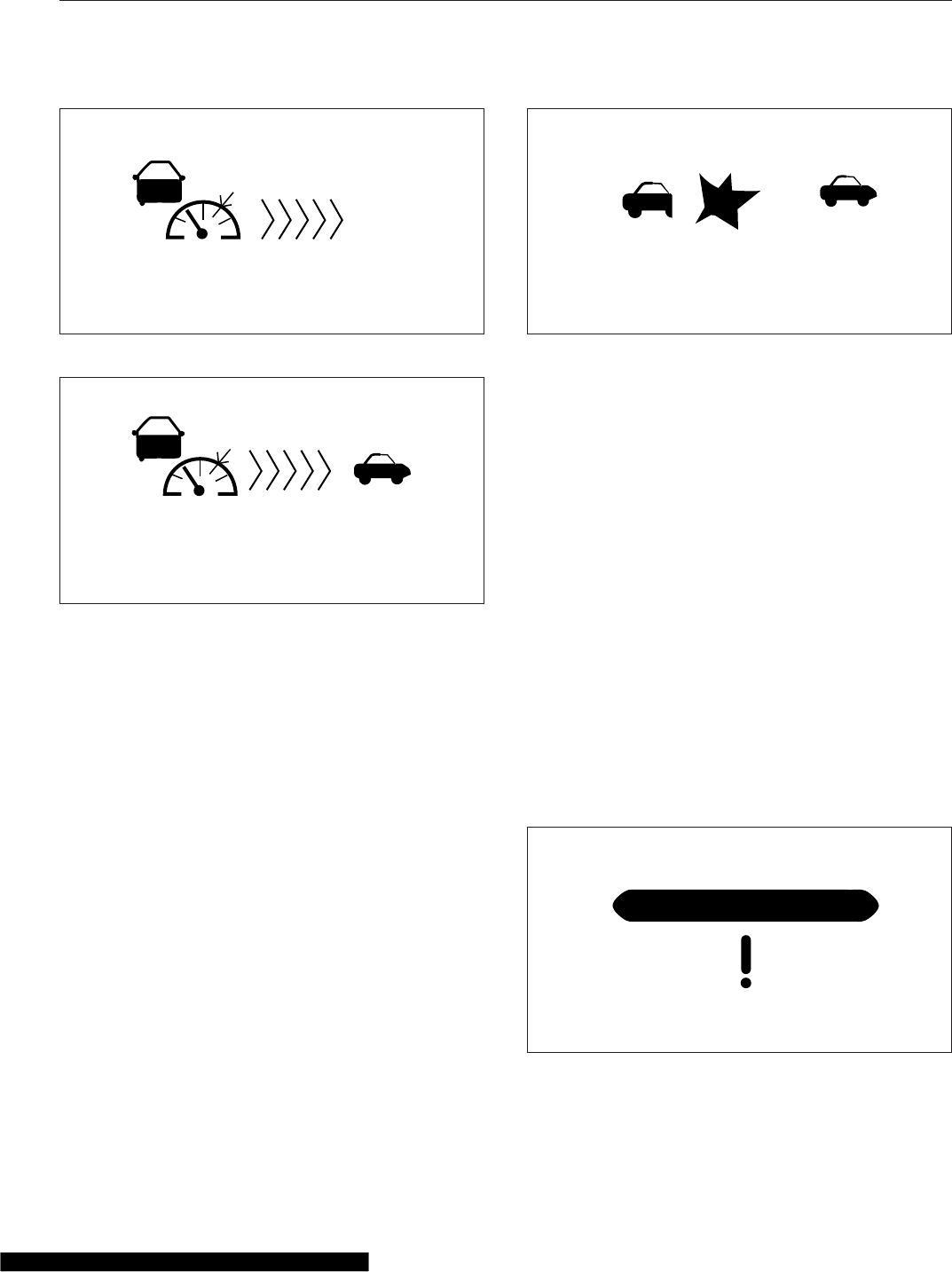
If the driver uses the accelerator pedal to override
the cruise control and approach a vehicle too closely,
the ACC will emit an audible alert and the display
background will turn yellow. The alert will end when
vehicle speed drops below the object’s speed and
the following distance is increased.
NOTE: The following distance alert does not
operate at speeds below 15 mph (25 km/h).
Collision Warning
If the object is traveling more slowly than the driver’s
vehicle, the CWS warns of an impending collision by
emitting an urgent audible alert and displaying the
collision warning symbol with a red background. See
Fig. 6.22.
The braking control will activate and slow the vehicle.
The driver must also initiate braking.
Collision Mitigation System (CMS)
The CMS provides the driver with audible and visual
alerts when the vehicle’s following distance could
result in a rear-end collision. If a potential rear-end
collision is developing and the driver does decelerate
the vehicle, OnGuard’s active braking automatically
applies the engine and service brakes to provide
braking power. The active braking application is in-
tended only to provide early braking as the driver is
recognizing and reacting to the situation.
IMPORTANT: CMS and active braking are not
operational at vehicle speeds below 15 mph (25
km/h).
Error Screens
IMPORTANT: The OnGuard collision safety sys-
tem is not operational when an error screen is
displayed.
If a system fault is detected, the OnGuard display
unit will immediately display an error screen like the
one shown in Fig. 6.23. The first error code transmit-
ted will be displayed first; additional faults (if any)
can be viewed using the up or down buttons. The
display does not show stored fault codes.
10/31/2014 f611145
Set: 60 MPH
Fig. 6.20, ACC Standby
10/31/2014 f611146
Set: 60 MPH 55 MPH
230 FT
Fig. 6.21, ACC Object Detected
10/31/2014 f611147
Set: 60 MPH 15 MPH
15 FT
Fig. 6.22, ACC Collision Warning
10/31/2014 f611148
ACC1 Link Error
DATA ERROR
Fig. 6.23, OnGuard Error Screen
Driver Assistance Features
6.9

If a fault occurs or OnGuard fails to properly track a
vehicle, take the vehicle in for service as soon as
possible. Standard cruise control will not function
with an active OnGuard system fault.
Refer to the OnGuard Collision Safety System Main-
tenance Manual MM-0951 for a full list of faults (ww-
w.Meritor.WABCO.com).
IMPORTANT: If the system fails to track an ob-
ject, look for signs of damage to the radar as-
sembly.
Additional Features
Press the MODE button to access the OnGuard dis-
play unit additional features from the CWS or ACC
main operating screen. Press the up and down ar-
rows to scroll through each menu, then press the
MODE button to select the value to be changed. In
edit mode, press the up or down arrows to change a
value setting, then press the MODE button to save
the setting. Pressing MODE in each feature screen
advances the display to the next feature.
The Display Control menu allows adjustment of the
alarm volume, LCD brightness, LCD contrast, and
U.S./metric unit conversion. See Fig. 6.24.
The component test menu provides verification of
system component operation and acts as a valuable
OnGuard system diagnostic tool. The header will dis-
play either COMPONENT TEST or ACC FUNCTION,
depending on the software release version of the On-
Guard system. The component test screen shown in
Fig. 6.25 provides access to the following compo-
nents (press the up or down arrows to scroll through
the menu):
•brake pedal position
•EBS brake switch
•CCVS brake switch
•clutch switch
•park brake switch
•accelerator pedal position
•driveline engaged
•cruise control enable
•cruise control set speed switch
•cruise control coast switch
•cruise control resume switch
•cruise control accelerate switch
•cruise control pause switch
Lane Departure Warning
Controls
The Lane Guidance lane departure warning system
monitors the vehicle’s position within the roadway
lane markings and sounds a warning in the cab
when the vehicle is about to stray outside its lane,
provided the turn signal is not on and the vehicle is
traveling at least 37 mph (60 km/h). The system in-
cludes a digital camera mounted high near the center
of the windshield inside the cab and speakers that
emit a sound similar to a rumble strip. The sound is
made on the side of the vehicle it’s straying toward,
prompting the driver to respond and steer away from
the sound and back into the center of the correct
lane.
10/31/2014 f611149
DISPLAY CONTROL
Alarm Volume
Alarm Tone
10
4
LCD Intensity
9
Fig. 6.24, Display Control Menu
10/31/2014 f611151
COMPONENT TEST
CCVS Brake Switch
Brake Pedal Position
ON
37%
ON
EBS Brake Switch
Fig. 6.25, Component Test Menu
Driver Assistance Features
6.10
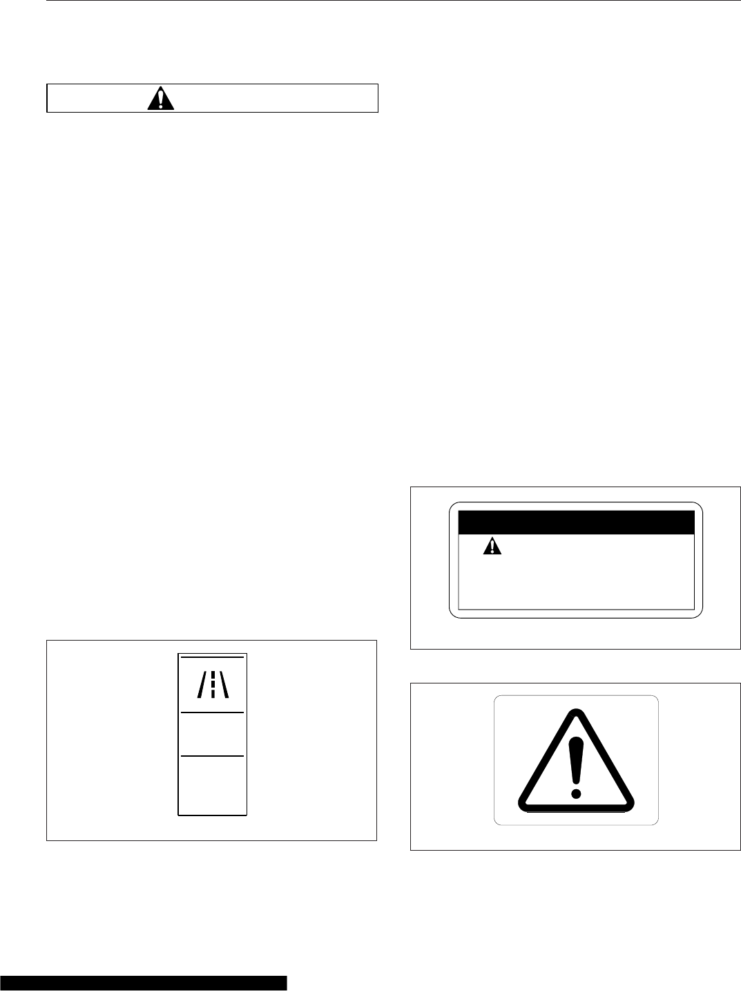
WARNING
The lane departure warning system is intended
only as an aid for a conscientious and alert
driver. The system may not indicate lane depar-
tures under certain conditions. Read carefully the
information in this manual to understand the cir-
cumstances under which this system may not
provide adequate lane departure warnings. Do
not rely solely on the system to safely operate
the vehicle. The system does not warn of all pos-
sible hazards. For example, the system cannot
prevent an accident if the driver is impaired or
not driving safely.
The lane departure warning system is not a sub-
stitute for safe driving procedures.
Failure to drive safely and use the system prop-
erly could result in personal injury and/or death
and severe property damage.
The lane departure warning system powers up each
time the ignition is turned to ON. The system con-
ducts a self test, and initiates test tones from the left
speaker and then the right speaker. Once the vehicle
is started and the system is ready, the LED in the
switch illuminates.
Press the LANE ALERT switch to temporarily disable
the lane departure warning system. See Fig. 6.26.
Some vehicles are equipped with a timer that auto-
matically re-enables the warning system after 15
minutes. On all other vehicles, the warning system
will remain disabled until the driver enables the sys-
tem by pressing the LANE ALERT switch again, or
the ignition is cycled off and then on.
When the vehicle approaches the lane markings on
either side, the system sense the activation of a turn
signal. If a turn signal has not been activated, the
system initiates the audible warning to alert the driver
that the vehicle is departing its current lane of travel.
The LANE SRCHNG warning light illuminates to indi-
cate the system is not fully functional. When the
warning light is on, the system audible alert may not
indicate a lane departure. Conditions that can cause
the warning light to illuminate include:
•The system is unable to detect lane markings.
•Vehicle speed is less than 37 mph (60 km/h).
•A system problem is detected.
Roll Stability System
The roll stability system may include the roll stability
advisor (RSA) only, or it may also include the roll sta-
bility control (RSC).
A decal (Fig. 6.27) on the auxiliary dash panel, and
an amber-colored dash indicator light (Fig. 6.28), in-
dicate that the vehicle is equipped with roll stability
system components.
LANE
ALERT
f61115601/05/2012
Fig. 6.26, Lane Departure Warning System Disable
Switch
lamp indicates traction
OR roll control event.
Follow instructions in
driver’s manual.
24−01204−000
07/11/2003 f080125
SAFETY INSTRUCTIONS
Fig. 6.27, Roll Stability Decal
06/26/2003 f602128
Fig. 6.28, Roll Stability Indicator Lamp
Driver Assistance Features
6.11
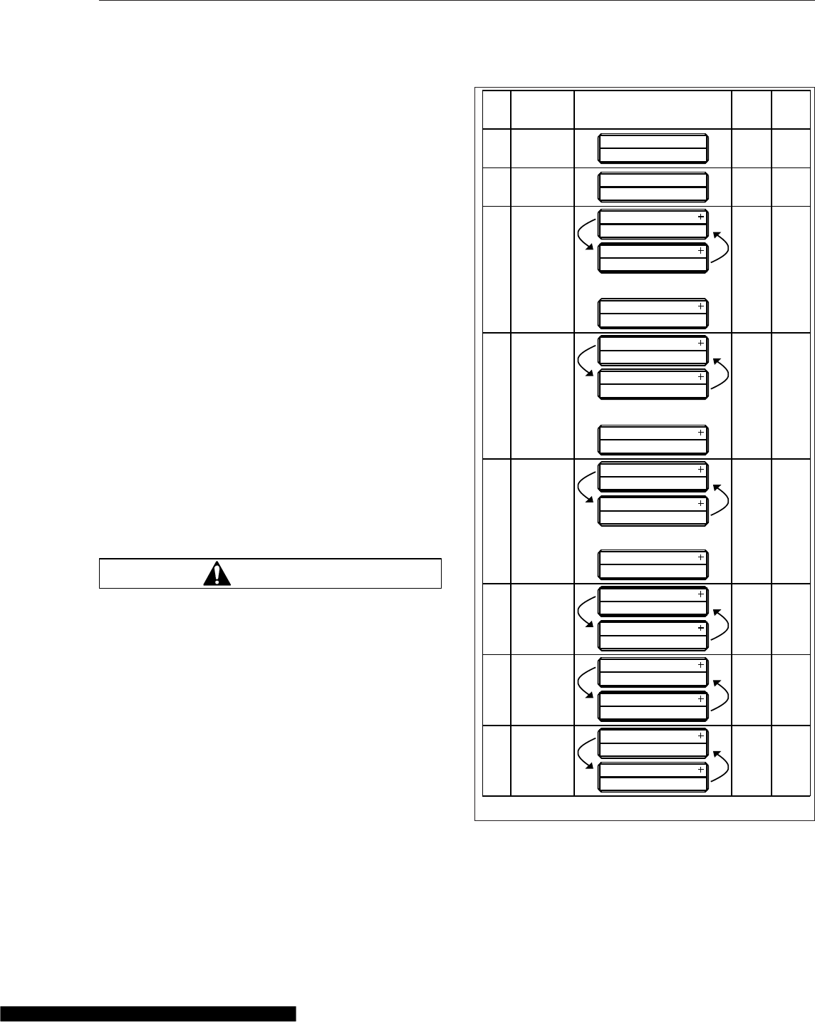
Roll Stability Advisor
IMPORTANT: This is not an advance warning
system. The roll stability advisor displays a mes-
sage only after the driving maneuver is com-
pleted.
The roll stability system uses a lateral-acceleration
sensor that monitors rollover risk. Shortly after a
curve, lane change, or other driving maneuver that
results in a rollover-risk detection, a dash warning
light illuminates, an audible tone sounds, and a driver
advisory message is displayed in the driver message
center. The purpose is to advise the driver that the
previous maneuver produced a rollover risk.
The roll stability advisor displays different text mes-
sages depending on the severity of the risk of each
occurrence of risky driving. From the highest risk
level to the lowest risk level, the system will sound
an audible alert, and display a message, as shown in
Fig. 6.29.
NOTE: The system will calculate and recom-
mend a speed reduction value. It may be differ-
ent than the values shown here.
Bring the vehicle to an authorized service facility if a
system failure message is displayed.
Roll Stability Control
WARNING
The Roll Stability Control system is intended only
as an aid for a conscientious and alert driver.
Carefully read the information in this manual to
understand this system and its limitations. The
Roll Stability Control system is not a substitute
for safe driving procedures. Failure to drive
safely, and use the system properly, could result
in personal injury and/or death and property
damage.
The roll stability control system automatically reduces
engine power, applies the engine brake, and/or ap-
plies the tractor and trailer brakes when the accelera-
tion sensor detects that the vehicle is at risk of rolling
over. The control can intervene even before an advi-
sory message is displayed.
The dash indicator light illuminates whenever the roll
stability control system intervenes.
Message to Display
41
MessageMSG
No.
System Fault1WARNING
RAC SYSTEM FAIL
ACTIVE SLOWING
ROLLOVER RISK
4 NoneRSC2
VERY HIGH RISK OF
ROLLOVER DETECTED
REDUCE SPEED
AT LEAST 11 KPH
REDUCE SPEED
AT LEAST 7 MPH
or in metric
19.6 10RSA Level 33
HIGH RISK OF
ROLLOVER DETECTED
REDUCE SPEED
AT LEAST 11 KPH
REDUCE SPEED
AT LEAST 7 MPH
or in metric
14 5RSA Level 24
ROLLOVER RISK
DETECTED
REDUCE SPEED
AT LEAST 11 KPH
or in metric
REDUCE SPEED
AT LEAST 7 MPH
8.4 2RSA Level 15
HARD BRAKING WITH
ABS ACTIVATED
LOOK AHEAD
BRAKE SOONER
14 0.5HBED Level 36
HARD BRAKING
DETECTED
LOOK AHEAD
BRAKE SOONER
14 0.5HBED Level 27
LOSS OF TRACTION
ABS ACTIVATED
ROAD SURFACE
MAY BE POOR
14 0.5HBED Level 18
07/25/2008 f040769
Display
Time:
Seconds
Buzzer
Time:
Seconds
Fig. 6.29, Roll Stability and Hard-Braking Warnings
Driver Assistance Features
6.12
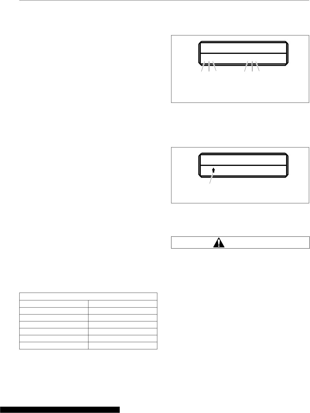
Hard-Braking Advisor
The hard-braking advisor uses the information from
the ABS wheel speed sensors to determine when
braking is severe enough to produce lockup at one
or more wheels on the tractor, and/or very rapid ve-
hicle deceleration. Shortly after a hard-braking event
occurs, an advisory message is displayed in the
driver message center, indicating that the braking
behavior was too aggressive for the current road sur-
face conditions. This system is not a replacement for
a driver’s good judgment. Sometimes it is necessary
to brake hard.
From the highest risk level to the lowest risk level,
the system will sound an audible alert, and display a
message, as shown in Fig. 6.29.
Trip/Leg Totals
The driver message center records the number of
messages received, and displays the number of
messages as counts. Roll stability advisor (RSA) and
hard-braking event data (HBED) counts can be
viewed in the trip advisory screen, and the leg advi-
sory screen.
Counts can be reset using the + key on the steering
wheel. Clearing RSA and HBED leg counts will also
reset the leg miles and leg hours. Clearing RSA and
HBED trip counts will also reset trip miles, trip hours,
leg miles, leg hours, and leg advisory counts. In ad-
dition, resetting leg miles will clear leg counts. Clear-
ing trip miles will reset miles, hours, and counts in
both the leg and trip screens.
The TRIP and LEG advisor screens count both the
roll stability advisories (ROLL) and hard-braking
events (BRK). For example, if during a TRIP, the
driver message center recorded the events in
Table 6.1, the message center would display as
shown in Fig. 6.30.
RSA/HBED Count
Message Received Message Counts
RSA Level 3 2
RSA Level 2 3
RSA Level 1 7
HBED Level 3 5
HBED Level 2 1
HBED Level 1 8
Table 6.1, RSA/HBED Count
If the count reaches more than 9 occurrences an up-
arrow symbol will appear, to indicate to the driver
that the count has exceeded 9 counts. See
Fig. 6.31.
Enhanced Stability Control
WARNING
Enhance Stability Control (ESC) is intended only
as an aid for a conscientious and alert driver.
Carefully read the information in this manual to
understand this system and its limitations. ESC
is not a substitute for safe driving procedures.
Failure to drive safely, and use the system prop-
erly, could result in personal injury and/or death
and property damage.
ESC offers the full capability of RSC (shown above)
with the added capability of complete directional sta-
bility (yaw control) in oversteer and understeer condi-
tions to reduce the likelihood of drift-out or jackknife.
The system determines where the driver is attempt-
ing to steer the vehicle and how much brake demand
is required in order to more precisely control the ve-
hicle in an emergency situation.
07/25/2008
TRIP ADVISORIES
237 ROLL 518 BRK
f040770
ABC DEF
A. RSA lev. 3 Count (2)
B. RSA lev. 2 Count (3)
C. RSA lev. 1 Count (7)
D. HBED lev. 3 Count (5)
E. HBED lev. 2 Count (1)
F. HBED lev. 1 Count (8)
Fig. 6.30, Trip Advisor Message Screen
07/25/2008
TRIP ADVISORIES
23 ROLL 518 BRK
f040771
A
A. RSA Lev. 1 has more than 9 counts.
Fig. 6.31, Trip Advisor Message Screen (more than 9
counts)
Driver Assistance Features
6.13

ESC works by constantly comparing the driver’s in-
tention with the vehicle’s actual behavior. The system
does this by monitoring systems such as wheel
speed, steering angle, yaw rate, lateral acceleration,
throttle position, and brake application. A central mi-
crocomputer analyzes the collected data and triggers
a response to keep the vehicle on course when an
unstable condition is detected.
When the system detects that the vehicle is at risk of
oversteering or understeering, it applies individual
tractor wheel end brakes and trailer brakes, activates
the engine retarder (if equipped), and/or cuts engine
power, depending on the severity. As a result, the
driver has full control over the vehicle until the sys-
tem detects a potential risk and intervenes accord-
ingly. ESC operates automatically; the driver does
not monitor or activate the system.
Driver Assistance Features
6.14

7
Seats and Restraints
Seats, General Information ......................................................... 7.1
Cascadia 2.0 High-Back Seat ....................................................... 7.2
Cascadia High-Back Seat .......................................................... 7.3
Sears Atlas Seat .................................................................. 7.4
Seat Belts and Tether Belts ......................................................... 7.5
Steering Wheel Air Bag ............................................................ 7.8
RollTek Rollover Protection System .................................................. 7.9
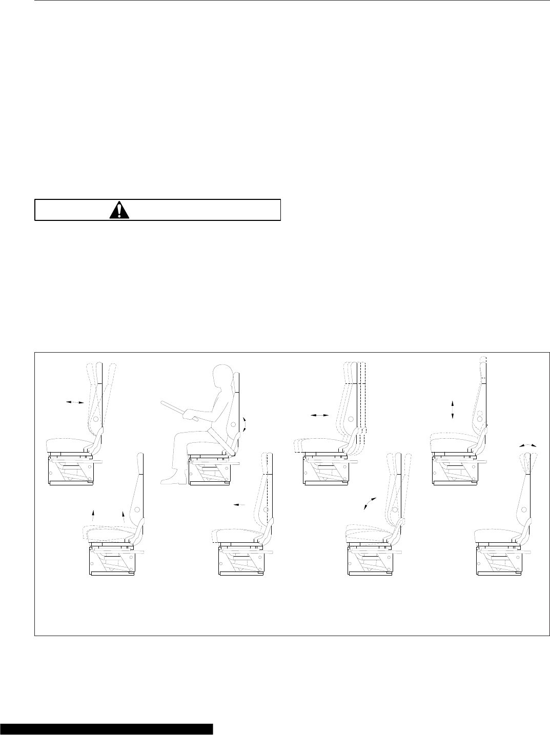
Seats, General Information
Unless otherwise noted, all seat adjustments should
be made while seated and before the engine is
started.
Due to the high degree of adjustability of mid- and
high-back air suspension seats, it is possible to com-
bine the seat back recline adjustment and the seat
slide adjustment so that the seat back contacts the
back wall. Use care when adjusting the seat to pre-
vent damage to the seat and the cab interior.
WARNING
Keep hands, tools, and other objects away from
the scissor points under the seats. Failure to do
so could cause personal injury.
The following is a description of adjustments that can
be made to various Freightliner-installed seats. Not
all seats have all of the adjustments listed below.
See Fig. 7.1.
•Backrest Tilt enables the backrest to pivot for-
ward or backward.
•Lumbar Support changes the shape of the
backrest to give more or less support to the
occupant’s lumbar (lower back) area. This ad-
justment is either mechanical or air controlled,
depending on the seat model.
•Fore/Aft Isolator feature reduces the amount of
road shock by isolating the occupant from the
motion of the vehicle, and allowing the upper
seat to move in a simple pendulum motion. A
lockout feature is used whenever the isolator is
not desired.
•Height Adjustment moves the entire seat up or
down. The adjustment is either manually- or
air-controlled, depending on the seat model.
•Bottom Cushion Angle (fore-and-aft bottom
cushion height) enables the occupant to raise
or lower the front or back of the bottom cush-
ion. This adjustment is easier to perform when
all weight is removed from the seat.
•Fore/Aft Seat Slide (seat track adjustment)
moves the entire seat forward or backward on
its track.
10/26/2000 f910149a
1
2
34
567
8
1. Backrest Tilt
2. Lumbar Support
3. Fore/Aft Isolator
4. Height Adjustment
5. Bottom Cushion Tilt (fore-and-aft
cushion height)
6. Fore/Aft Seat Slide (seat track
adjustment)
7. Seat Tilt
8. Headrest Adjustment
Fig. 7.1, General Seat Adjustments
Seats and Restraints
7.1
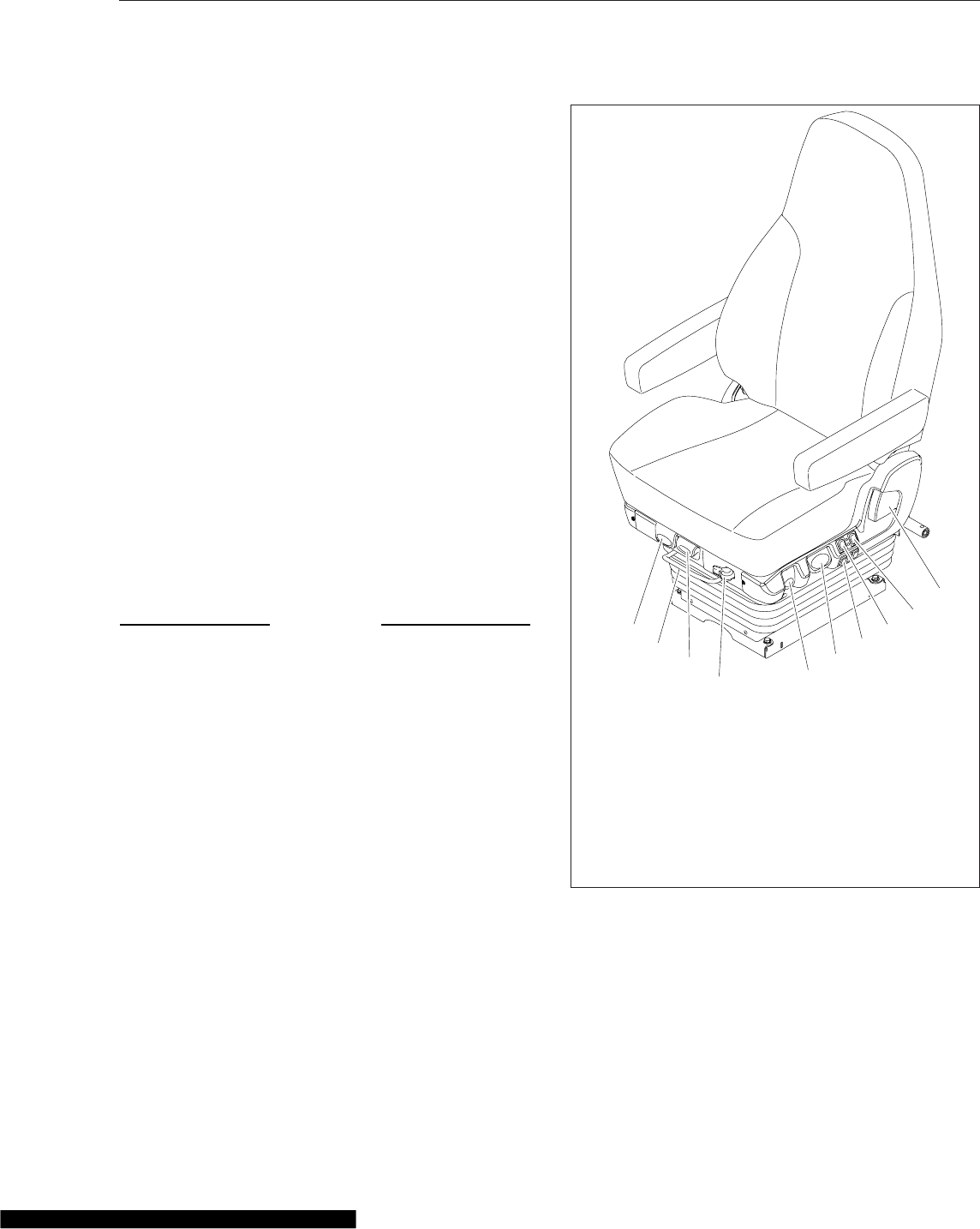
•Seat Tilt allows the seat assembly (back and
bottom cushions) to tilt forward or backward.
•Headrest Adjustment changes the angle of the
upper part of the backrest to provide head and
upper back support.
Cascadia 2.0 High-Back Seat
See Fig. 7.2 for seat adjustment controls. Not all
models of the Cascadia 2.0 Hi-Back seat have all the
adjustments listed below.
Recline
Pull the recline handle to adjust the backrest tilt.
Seat Heating/Ventilation
Use the forward switch to turn the seat heater and
ventilation ON or OFF. To turn on the heat, push the
top of the switch. To turn on the ventilation, push the
bottom of the switch. To turn off the heat or ventila-
tion, move the switch to the middle position. To ad-
just the heat or ventilation, Use the rear button to
adjust seat heating or ventilation. Three settings are
available: low, medium, and high. See Fig. 7.3.
NOTICE
Do not install seat covers on seats with heating
and ventilation. Do not cover the seat with blan-
kets, clothing, or pillows. Blocking the air flow
through the cushions can overheat and damage
the seat.
IMPORTANT: Turn off seat heating/ventilation
when the seat is unoccupied.
Lumbar Support
Press the forward button to adjust lower lumbar sup-
port, the middle button to adjust upper lumbar sup-
port, and the rear button to adjust side support.
Height Adjustment
Pull or push the lever to adjust seat height.
Shock Absorber Adjustment
Move the lever down to increase damping on rough
roads, or up to decrease damping on flat roads.
Fore/Aft Isolator
Rotate the isolator knob to the left to lock the isola-
tor, or to the right to allow movement.
05/11/2012 f910682
1
2
3
4
5
6
7
8
9
10
1. Recline Handle
2. Heat/Ventilation Adjustment Switch
3. Heat/Ventilation ON/OFF Switch
4. Lumbar and Side Support Switches
5. Height Adjustment Lever
6. Shock Absorber Adjustment Lever
7. Fore/Aft Isolator Lever
8. Bottom Cushion Extension Lever
9. Seat Fore/Aft Slide Lever
10. Seat Tilt Lever
Fig. 7.2, Cascadia 2.0 Hi-Back Seat
Seats and Restraints
7.2

Bottom Cushion Extension
Pull the lever to move the seat cushion forwards or
backwards. The cushion moves 2-3/8 inches (60
mm) in 3/8-inch (10-mm) increments.
Seat Fore/Aft Slide
Lift the lever to slide the seat forward or backward.
Release the lever to lock the seat in position.
Seat Tilt
Pull the lever and lean back to tilt the seat back-
wards. Three positions are available.
Armrest Angle
To adjust the armrest angle, tilt the armrest to the
highest position, then down to the lowest position,
then to the desired position.
Cascadia High-Back Seat
See Fig. 7.4 for seat adjustment controls.
Backrest Tilt
To tilt the backrest, lean forward slightly to remove
pressure from the cushion, then turn the knob for-
ward or rearward to achieve the desired position.
Lumbar Support
To adjust the lumbar support, use the lumbar support
switches on the side of the seat.
Height Adjustment
To raise or lower the height of the seat, use the
height adjustment switch on the side of the seat.
Bottom Cushion Extension
To adjust the fore-and-aft position of the seat cush-
ion, remove your weight from the seat, then lift up
and pull forward on the cushion adjustment handle.
To return the cushion to the aft position, lift up and
push rearward.
Fore/Aft Seat Slide
To adjust the fore-and-aft position of the entire seat,
move the fore-and-aft seat adjustment lever to the
left and slide the seat forward or backward to the
desired position. Move the lever back to its original
position to lock the seat in place.
Fore/Aft Isolator
To engage the isolator, turn the isolator knob rear-
ward to the unlocked position. Turn the isolator knob
forward to the locked position when the isolator fea-
ture is not desired.
Shock Absorber
To adjust the amount of damping the shock absorber
provides, move the lever up to increase damping;
move the lever down to decrease damping.
Front Cushion Height
To adjust the height of the front of the cushion, re-
move your weight from the seat, then turn the adjust-
ment knob toward the front of the seat (clockwise) to
increase cushion height. To lower the cushion height,
turn the adjustment knob toward the rear of the seat
(counterclockwise).
Rear Cushion Height
To adjust the height of the rear of the seat cushion,
remove your weight from the seat and turn the rear
cushion adjustment knob to one of three positions.
05/08/2012 f910683
1
2
3
45
1. Ventilation ON
2. Heat/Ventilation OFF
3. Heat ON
4. Heat/Ventilation ON/OFF Switch
5. Heat/Ventilation Adjustment Switch
Fig. 7.3, Cascadia 2.0 Hi-Back Seat Heat/Ventilation
Controls
Seats and Restraints
7.3
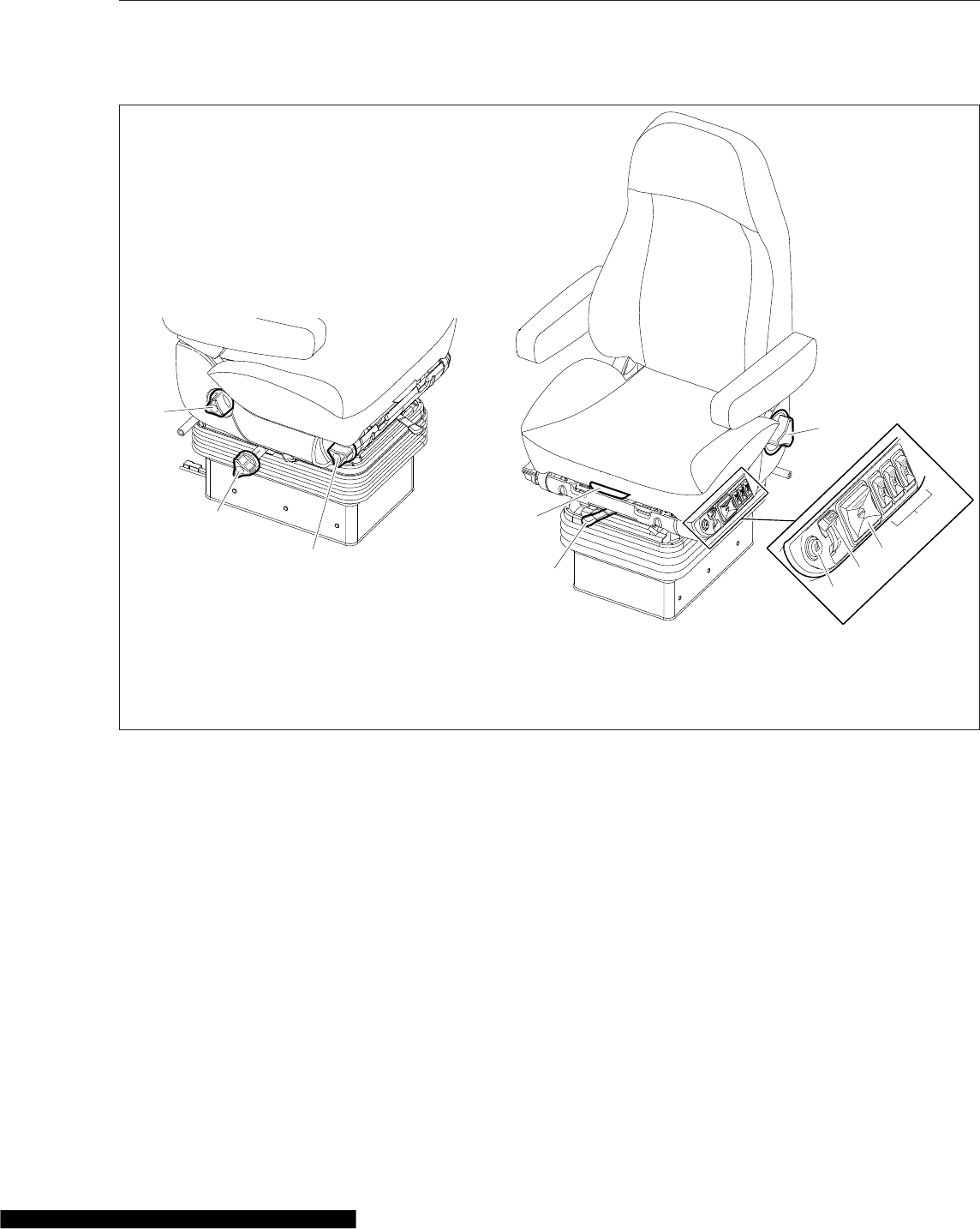
Heater
To turn on the heat option, press the button. To turn
off the heat option, press the button again. If the ve-
hicle has Optimized Idle, seat heating will not oper-
ate with the key in accessory mode. Optimized Idle
may also turn seat heating off to reduce stress on
the batteries. Refer to Chapter 11 for more informa-
tion.
Sears Atlas Seat
See Fig. 7.5 for seat adjustment controls.
Backrest Tilt
Pull upward on the recliner handle, move the back-
rest to the desired position and release the handle.
Lumbar Support
Rear rocker switch: Push forward to inflate the lower
lumbar bag; push rearward to deflate the bag. Center
rocker switch: Push forward to inflate the upper lum-
bar bag; push rearward to deflate the bag.
Fore/Aft Seat Slide
To adjust the fore-and-aft position of the entire seat,
squeeze the fore/aft slide lock against the adjustment
bail, and lift the bail up. See Fig. 7.6. Slide the seat
f910576
5
4
7
8
9
10
6
07/18/2007
1
2
3
1. Rear Cushion Height Adjustment
Knob
2. Fore/Aft Isolator
3. Front Cushion Height Adjustment
Knob
4. Bottom Cushion Extension Handle
5. Fore/Aft Seat Slide Lever
6. Backrest Tilt Knob
7. Heater Button
8. Shock Absorber Lever
9. Height Adjustment Switch
10 Lumbar Support Switches
Fig. 7.4, Cascadia Hi Back Seat
Seats and Restraints
7.4
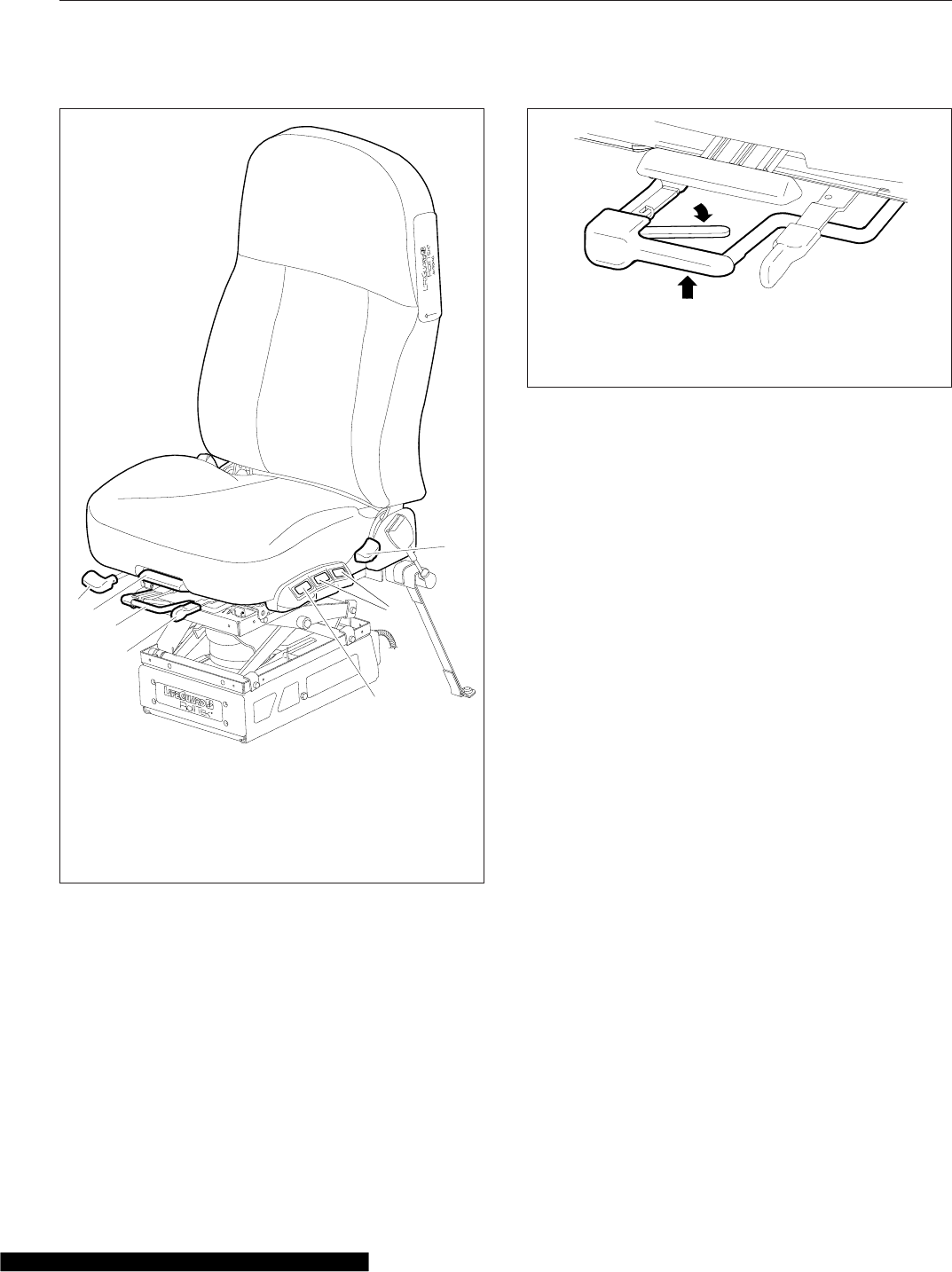
forward or backward to the desired position. Release
the bail and fore/aft slide lock, to its original position,
to lock the seat in place.
Bottom Cushion Tilt
Lift the handle upward and move the seat cushion to
the desired position. Three positions are available.
Armrest Angle
Rotate the control knob, located on the underside of
the armrest, to set the desired angle of the armrest.
Isolator
Position the handle to the left to allow isolation
movement. Position the handle to the right to lock-
out isolation movement.
Suspension Inflation/Deflation
Push forward on the gray rocker switch to inflate and
raise the suspension; push rearward to deflate and
lower the suspension.
Seat Extension
Rotate the handle upward to disengage, then move
the seat cushion to the desired position and release
the lever. Three positions are available.
Seat Belts and Tether Belts
Seat belt assemblies are designed to secure persons
in the vehicle to help reduce the chance of injury, or
the amount of injury, resulting from accidents or sud-
den stops. For this reason, Daimler Trucks North
America LLC (DTNA) urges that the driver and all
passengers, regardless of age or physical condition,
use seat belts when riding in the vehicle.
10/15/2007 f910597
1
2
3
4
5
6
7
1. Isolator Lever
2. Fore/Aft Seat Slide
Lever
3. Bottom Cushion Tilt
Handle
4. Seat Extension Lever
5. Backrest Tilt Lever
6. Lumbar Support
Switches
7. Suspension Inflation/
Deflation Switch
Fig. 7.5, Sears Atlas Seat
10/15/2007 f910599
A
B
A. Squeeze the fore-and-aft slide lock against the
adjustment bail.
B. Lift up the adjustment bail.
Fig. 7.6, Fore/Aft Slide Adjustment, Sears Atlas Seat
Seats and Restraints
7.5
WARNING
Always use the vehicle’s seat belt system when
operating the vehicle. Failure to do so can result
in severe personal injury or death.
Seat belt assemblies in DTNA vehicles meet Federal
Motor Vehicle Safety Standard 209, "Type 1" and
"Type 2" requirements.
When transporting a child, always use a child re-
straint system or the vehicle seat belts as appropri-
ate. To determine whether a child restraint system is
required, review and comply with applicable state
and local laws. Any child restraint used must comply
with Federal Motor Vehicle Safety Standard 213,
"Child Restraint Systems." When providing a child
restraint system, always carefully read and follow all
instructions pertaining to installation and usage for
the child. Make certain the child remains in the re-
straint system at all times when the vehicle is in
motion.
In addition to seat belt assemblies, tether belts are
installed on suspension-type seats. Tether belts help
secure the seat to the floor and are intended to re-
strain the seat and seat belt in case of an accident or
sudden stop.
IMPORTANT: Seat belts have a finite life which
may be much shorter than the life of the vehicle.
Regular inspections and replacement as needed
are the only assurance of adequate seat belt
security over the life of the vehicle.
Seat Belt Inspection
WARNING
Inspect and maintain seat belts. When any part of
a seat belt system needs replacement, the entire
seat belt must be replaced, both retractor and
buckle side. Any time a vehicle is involved in an
accident, and the seat belt system was in use,
the entire vehicle seat belt system must be re-
placed before operating the vehicle. Do not at-
tempt to modify the seat belt system; doing so
could change the effectiveness of the system.
Failure to replace worn or damaged seat belts, or
making any modifications to the system, may re-
sult in personal injury or death.
Inspect the seat belts and tether belts (if so
equipped).
1. Check the web for fraying, cuts, extreme dirt and
dust, or for severe fading from exposure to sun-
light, especially near the buckle latch plate and in
the D-loop guide area.
2. Check operation of the buckle, latch, Komfort
Latch or Sliding Komfort Latch (if equipped), web
retractor, and upper seat belt mount on the door
pillar. Check all visible components for wear or
damage.
3. Check the seat belt and tether belt connection
points and tighten any that are loose.
Seat Belt Operation
WARNING
Wear three-point seat belts only as described
below. Three-point seat belts are designed to be
worn by one person at a time. In case of an acci-
dent or sudden stop, personal injury or death
could result from misuse.
Fasten the seat belts before driving. Fastening a
three-point seat belt while driving creates a haz-
ard.
When engaged and used properly, the Komfort Latch
(Fig. 7.7) and the Sliding Komfort Latch (Fig. 7.8)
introduce a small amount of slack into the seat belt,
resulting in a more comfortable ride.
1. Slowly pull the link end of the seat belt out of the
retractor and pull it across your lap (from out-
board to inboard) far enough to engage the
buckle. If the retractor locks too soon, allow the
belt to retract slightly, then slowly pull it out
again. See Fig. 7.9.
2. Fasten the seat belt by pushing the latch into the
buckle. Listen for an audible click.
3. Tug on the seat belt to make sure it is securely
fastened. If the buckle unlatches, repeat this
step. If the problem continues, replace the seat
belt.
4. Snug the seat belt to your waist.
Seats and Restraints
7.6
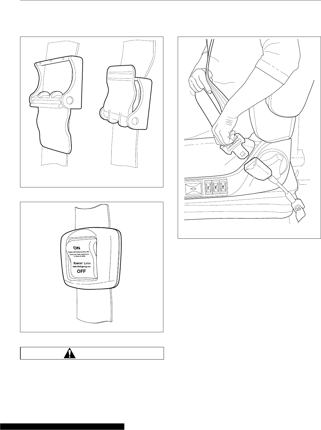
WARNING
Before activating the Komfort Latch or the Slid-
ing Komfort Latch, make sure the amount of
slack in the shoulder strap is set as described
below. Excess slack in the shoulder strap re-
duces the effectiveness of the seat belt, and in-
creases the risk of injury or death in an accident.
5. Position the shoulder strap diagonally across
your chest with the adjustable D-loop bracket (if
equipped). The shoulder strap must be centered
on your shoulder and chest, away from your face
and neck. See Fig. 7.10. If desired, engage the
Komfort Latch or Sliding Komfort Latch as fol-
lows.
If equipped with a Sliding Komfort Latch, make
sure that the shoulder strap is snug against your
chest. Without loosening the shoulder strap,
push the Sliding Komfort Latch switch to the
"ON" position. See Fig. 7.8. To activate the latch
lean forward until you hear a click. This will allow
03/11/2010 f910620
AB
A. Disengaged B. Engaged
Fig. 7.7, Komfort Latch
11/18/2010 f910621a
Fig. 7.8, Sliding Komfort Latch
07/02/2007 f910578
1
2
1. Latch 2. Buckle
Fig. 7.9, Three-Point Seat Belt Operation
Seats and Restraints
7.7
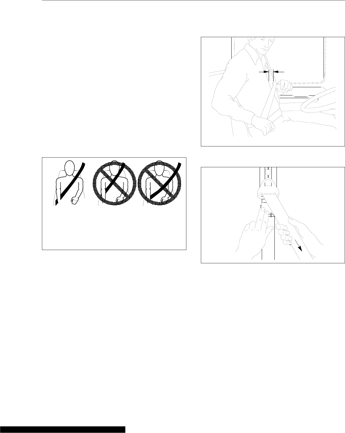
for approximately 1 inch (2.5 cm) of slack be-
tween your chest and the shoulder harness.
Once engaged, the latch will allow you to lean
forward about 5 inches (13 cm) without having to
reset the latch. Leaning forward more than 5
inches (13 cm) will disengage the Sliding Kom-
fort Latch, requiring it to be reset.
If equipped with a Komfort Latch, pull on the
shoulder strap to lessen the pressure of the strap
on your shoulder and chest. Allow no more than
1 inch (2.5 cm) of slack between your chest and
the shoulder harness. More slack can signifi-
cantly reduce the seat belt effectiveness in an
accident or a sudden stop. While holding the belt
slack, press the Komfort Latch lever up, clamp-
ing the seat belt webbing (Fig. 7.11 and
Fig. 7.12).
6. Unbuckle the seat belt and release the Komfort
Latch or the Sliding Komfort Latch as follows.
If equipped with a Sliding Komfort Latch, un-
buckle the seat belt, then tug on the shoulder
belt to release the Sliding Komfort Latch, or
press the Sliding Komfort latch to the "OFF" po-
sition, then unbuckle the seat belt.
If equipped with a Komfort Latch, unbuckle the
seat belt, then release the Komfort Latch by giv-
ing the shoulder belt a quick tug. If you lean for-
ward against the shoulder belt, the Komfort Latch
will automatically release, and will need to be
reset.
NOTE: Neither the Komfort Latch nor the Sliding
Komfort Latch need to be manually released in
an emergency situation. Each will release by
itself under rough road or other abnormal condi-
tions. Make sure the seat belt is completely re-
tracted when it is not in use.
Steering Wheel Air Bag
Operation
NOTE: Only vehicles with the letters "SRS"
molded into the steering wheel center pad are
equipped with a steering wheel air bag.
The air bag, when used with seat belts, provides ad-
ditional protection to the driver in severe frontal colli-
sions. Steering wheel air bags are designed to inflate
only in severe frontal collisions. The driver and the
08/09/2010 f910634
ABC
A. Correct—Belt is centered on your shoulder and
chest, away from your face and neck.
B. Wrong—Belt must not rub against face or neck.
C. Wrong—Belt must not hang off shoulder.
Fig. 7.10, Proper Shoulder Strap Fit
A
01/06/95 f910048a
A. 1 Inch (2.5 cm) Maximum
Fig. 7.11, Adjusting Shoulder Harness Clearance,
Komfort Latch
11/02/95 f910144
Fig. 7.12, Locking the Komfort Latch
Seats and Restraints
7.8
passenger should always wear seat belts. The steer-
ing wheel air bag will activate during a collision even
if the seat belts are not fastened, but the system is
designed to provide protection to the occupant only
when the seat belts are fastened.
WARNING
Keep all heavy objects in the cab secured. Do not
place objects on the steering wheel or between
you and the steering wheel. Any such objects
may cause harm during an accident. Keep your
hands on the sides and lower portion of the
steering wheel. Failure to follow these instruc-
tions may result in death or personal injury.
For maximum protection in a collision, always be in a
normal seated position with your back against the
seat back and your head upright. Fasten your seat
belt and ensure that it is properly positioned on your
body as described under the "Seat Belt Operation"
heading. Since the air bag inflates with considerable
speed and force, a proper seat position will help
keep you a safe distance from the inflating air bag.
Inspection and Service
WARNING
Do not attempt to service or modify the air bag
system. Unintentional or improper air bag deploy-
ment could cause severe bodily injury or death.
Contact an authorized Freightliner service facility
for all service and maintenance.
The air bag system contains components that
use combustible chemicals. Do not cut, drill,
braze, solder, weld, strike, or probe the air bag
components. Keep all liquids and chemicals
away from air bag components.
The surface of the deployed air bag may contain
small amounts of sodium hydroxide (which is a
by-product of the gas generant combustion) and
metallic sodium. Sodium hydroxide may be irri-
tating to the skin and eyes. Immediately wash
your hands and exposed skin areas with a mild
soap and water. Flush your eyes immediately if
exposed to sodium hydroxide.
The operational readiness of the air bag system is
indicated by the supplemental restraint system (SRS)
indicator on the dash. The SRS indicator illuminates
for several seconds when the ignition is turned on,
and then it goes off. The indicator will remain on if
there is a problem with the air bag system. The ve-
hicle should be serviced if the SRS indicator does
not illuminate when the ignition is turned on, or if the
SRS indicator remains on.
The air bag module may contain perchlorate mate-
rial; for information, see www.dtsc.ca.gov/
hazardouswaste/perchlorate. Special handling may
apply; follow appropriate rules and regulations when
disposing of materials.
For all service and maintenance, contact an autho-
rized Freightliner service facility.
RollTek Rollover Protection
System
Identification
Only seats with the RollTek module under the seat
and the molded side-roll air bag cover on the upper
side of the seat back are equipped with the RollTek
rollover protection system; see Fig. 7.13. RollTek
may be installed in one of the following configura-
tions:
•driver seat only or driver and passenger seats
•driver seat only, with an optional steering
wheel frontal air bag
•driver and passenger seats, with an optional
steering wheel frontal air bag
Operation
The RollTek system, when used with seat belts, pro-
vides additional protection to the driver and passen-
ger (if equipped with a passenger-side system) in
rollover accidents. The RollTek system provides a
significant increase in seat stability during a rollover.
Vehicles equipped with RollTek rollover protection
have a sensor mounted in the seat base that acti-
vates the side-roll air bag and seat pull-down device
during a rollover.
When the RollTek module senses a rollover, the
module triggers gas cylinders mounted in the base of
the seat. The gas cylinders activate the power
cinches that then tighten the lap and shoulder belts
against the occupant of the seat and lower the seat
suspension, moving the occupant down and away
from the steering wheel and ceiling. The side-roll air
Seats and Restraints
7.9
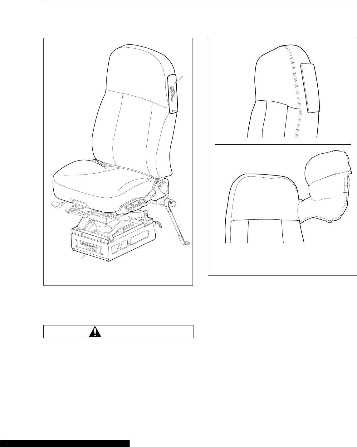
bag deploys from the outboard side of the seat as
the seat is pulled down to its lowest position. See
Fig. 7.14.
WARNING
Always use the seat belts when operating the ve-
hicle. Failure to do so can result in severe per-
sonal injury or death. Do not place infants and
children in seats equipped with the RollTek sys-
tem. The RollTek system is designed for adults
only. Doing so could result in severe bodily in-
jury or death. Keep all heavy objects in the cab
secured. Do not place objects on the seat back
or block the side-roll air bag. Objects that block
the side-roll air bag may prevent proper inflation
and could result in serious injury or death.
The RollTek system will activate during a rollover
even if the seat belts are not fastened, but the
RollTek system is only designed to provide protection
to the occupant when the seat belts are fastened.
For vehicles with the RollTek system(s) only, de-
vice(s) deploy as follows:
•Rollover Crash—occupant seat belt pretension-
ing, seat pretensioning, and side-roll air bag at
the proper time
•Frontal Crash—no devices deployed
10/15/2007 f910598
1
2
1. RollTek Module
2. Side-Roll Air Bag Cover
Fig. 7.13, RollTek Protection System Components
07/03/2007
A
B
f910579
A. Side-roll air bag contained in seat.
B. Side-roll air bag deployed.
Fig. 7.14, Side-Roll Air Bag
Seats and Restraints
7.10

For vehicles with the RollTek system(s) and frontal
steering wheel air bag, device(s) deploy as follows:
•Rollover Crash—occupant seat belt pretension-
ing, seat pretensioning, and side-roll air bag at
the proper time
•Frontal Crash—steering wheel air bag, occu-
pant seat belt pretensioning, seat pretension-
ing, and the side-roll air bag at the proper time
Inspection and Service
WARNING
Keep hands and tools away from the scissor
points under the seats.
The RollTek system contains components that
use combustible chemicals. Do not cut, drill,
braze, solder, weld, strike, or probe any part of
the RollTek system. Keep all liquids and chemi-
cals away from the RollTek components.
Do not attempt to service or modify the RollTek
system. Unintentional or improper deployment of
the RollTek system could cause severe bodily
injury or death. Contact an authorized Freight-
liner service facility for all service and mainte-
nance.
IMPORTANT: The RollTek system must be re-
placed after being activated. Damaged seat
belts and tethers, or seat belts and tethers that
were worn in an accident, must be replaced,
and their anchoring points must be checked.
The operational readiness of the RollTek system is
indicated by the supplemental restraint system (SRS)
indicator on the dash. The SRS indicator illuminates
for several seconds when the ignition is turned on,
and then it goes off. The indicator will remain on if
there is a problem with the air bag or RollTek sys-
tem. The vehicle must be serviced if the SRS indica-
tor does not illuminate when the ignition is turned on,
or if the SRS indicator remains on.
The air bag module may contain perchlorate mate-
rial; for information, see www.dtsc.ca.gov/
hazardouswaste/perchlorate. Special handling may
apply; follow appropriate rules and regulations when
disposing of materials.
For all service and maintenance, contact an autho-
rized Freightliner service facility.
Seats and Restraints
7.11

8
Climate Control
Cab Climate Control Panel ......................................................... 8.1
Sleeper Climate Control Panel ...................................................... 8.2
ParkSmart™HVAC System ......................................................... 8.3
Accessory Heaters ................................................................ 8.5
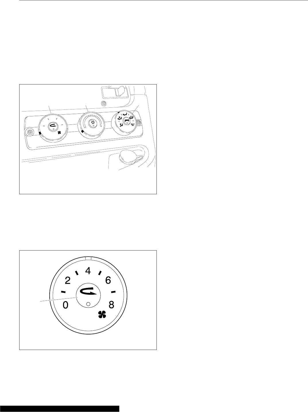
Cab Climate Control Panel
The standard cab climate control panel has a fan
switch with a recirculation button, temperature control
switch with an A/C button, and a mode control
switch. See Fig. 8.1. Sleeper cabs are also equipped
with a bunk override button.
Fan Switch
The fan switch activates the fan, which forces fresh
air or recirculated air through the air outlets. The fan
switch has eight fan speed settings and an OFF po-
sition. See Fig. 8.2.
To operate the fan switch, turn the fan switch clock-
wise to increase airflow; turn the fan switch counter-
clockwise to decrease airflow.
There is a two-second delay between the time the
engine is started and the blower is operational. It can
take an additional four seconds for the blower to
reach high speed. The blower motor performs a self-
test immediately after the engine is started, which
causes the delay. If the vehicle has Optimized Idle,
the fan will not operate with the key in accessory
mode. Optimized Idle may also turn the fan off to
reduce stress on the batteries. Refer to Chapter 11
for more information.
Recirculation
Recirculation mode limits the amount of outside air
entering the cab. Press the recirculation button to
prevent dusty or smoky air from entering the cab.
See Fig. 8.2. Recirculation mode can also decrease
the time required to cool or heat the cab interior dur-
ing extreme outside temperature conditions. When
the recirculation mode is turned on, the amber indi-
cator on the recirculation button will illuminate.
The recirculation button will not work when the mode
control switch is in either defog or defrost modes.
NOTE: To prevent the buildup of odors or oxy-
gen depletion inside the cab, the system
switches from full recirculation mode to partial
recirculation mode after 20 minutes. In ex-
tremely dusty or smoky conditions, the partial
recirculation mode can be overridden by press-
ing the recirculation button twice to obtain full
recirculation mode. This resets the 20-minute
timer.
Temperature Control Switch
The temperature control switch is used to select the
desired temperature in the cab. Turn the switch
counterclockwise for cool air, or clockwise for hot air.
See Fig. 8.3.
Air Conditioning Button
The air conditioner (A/C) cools and dehumidifies the
air inside the cab. Press the A/C button, located in
the center of the temperature control switch, to turn
the air conditioner on and off. See Fig. 8.3.
A/C will be automatically disabled when:
0
24
8
6
07/20/2006 f831701
12 3
1. Fan Switch
2. Temperature Control Switch
3. Mode Control Switch
Fig. 8.1, Cab Climate Control Panel
06/08/2007 f610946
1
1. Recirculation Button
Fig. 8.2, Fan Switch
Climate Control
8.1
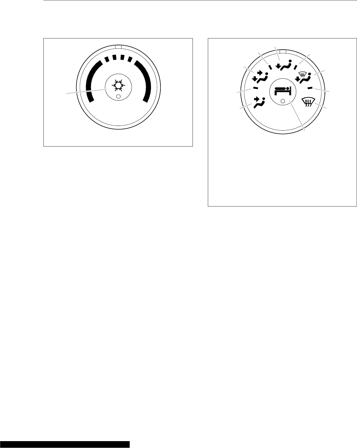
•outside air temperature is low enough to make
the A/C ineffective;
•engine is running at extremely low rpm;
•conditions exist that result in the climate con-
trol system going into protection mode.
Mode Control Switch
The mode control switch allows the driver to control
the flow of air through the face outlets, the floor out-
lets, the defrost (windshield) outlets, or a combination
of these outlets. See Fig. 8.4.
•Face Mode: Directs all airflow through the face
or instrument panel outlets.
•Bi-Level Mode: Directs the airflow equally to
the face outlets and the floor outlets.
•Floor Mode: Directs all airflow through the floor
outlets.
•Floor/Defrost Mode: Directs the airflow equally
to the floor outlets and the defrost outlets.
•Defrost Mode: Directs all airflow through the
defrost outlets.
Bunk Override Button
The bunk override button, equipped on sleeper cabs
only, allows the driver to control the sleeper heat and
A/C settings from the cab. See Fig. 8.4.
Press the bunk override button to turn the sleeper
heat or A/C on. An amber indicator will illuminate
when bunk override mode is activated.
Press the bunk override button again to turn bunk
override mode off. Adjusting the sleeper climate con-
trols at any time will also cause the bunk override
mode to cancel.
Sleeper Climate Control Panel
The standard sleeper climate control panel has a fan
switch and a temperature control switch with an A/C
button.
If the bunk override button has been activated, the
override mode can be canceled by changing the
sleeper fan speed or temperature setting. The cli-
mate control system will then operate from the
sleeper controls.
Fan Switch
The fan switch activates the fan, which forces air
through the air outlets. The fan switch has eight fan
speeds and an OFF position. See Fig. 8.5.
To operate the fan switch, turn the switch clockwise
to increase airflow; turn the fan switch counterclock-
wise to decrease airflow. If the vehicle has Optimized
06/08/2007 f610947
1
1. Air Conditioning Button
Fig. 8.3, Temperature Control Switch
06/08/2007 f610948
1
2
3
4
5
6
7
8
9
10
1. Face Mode
2. Selection Between Face Mode and Bi-Level Mode
3. Bi-Level Mode
4. Selection Between Bi-Level Mode and Floor Mode
5. Floor Mode
6. Selection Between Floor Mode and Defog Mode
7. Defog Mode
8. Selection Between Defog Mode and Defrost Mode
9. Defrost Mode
10. Bunk Override Button (on sleeper-cabs only)
Fig. 8.4, Mode Control Switch With Bunk Override
Button
Climate Control
8.2
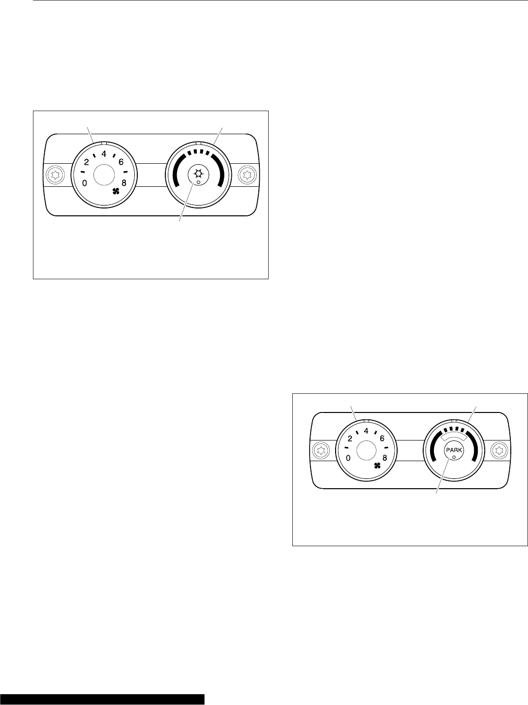
Idle, the fan will not operate with the key in acces-
sory mode. Optimized Idle may also turn the fan off
to reduce stress on the batteries. Refer to Chap-
ter 11 for more information.
NOTE: When the cab air conditioner (A/C) is on,
the sleeper fan will operate at low speed even if
the sleeper fan switch is in the off position. This
is necessary to protect the evaporator in the
sleeper heater and air conditioner system from
freezing. In lower fan speed settings, a slight
increase in airflow levels may appear at times,
as the control acts to regulate the evaporator
temperature.
Temperature Control Switch
The temperature control switch is used to select the
desired temperature in the sleeper. Turn the switch
counterclockwise for cool air, or clockwise for hot air.
Air Conditioning Button
The A/C cools and dehumidifies the air inside the
sleeper. Press the air conditioning button, located in
the center of the temperature control switch, to turn
the A/C on and off.
ParkSmart™HVAC System
There are two variations of the ParkSmart vehicle
configuration. The standard configuration is the most
common, and includes all vehicles without Detroit
Diesel Optimized Idle (O/I). The second variation in-
cludes vehicles equipped with Detroit Diesel Opti-
mized Idle (O/I). Both configurations are operated in
the same way, the differences are in how the batter-
ies and charging system are configured. Refer to
"Standard Vehicle Configuration" or "Vehicles with
Detroit Diesel Optimized Idle" below for more infor-
mation on your vehicle.
Standard Vehicle Configuration
The ParkSmart™climate control panel replaces the
standard sleeper control panel in ParkSmart-
equipped sleeper cabs. The ParkSmart HVAC sys-
tem is designed to maintain a comfortable tempera-
ture inside the sleeper, and can operate in
combination with the cab climate control system
when the vehicle is running, or independently when
the vehicle is parked. It uses a set of four dedicated
batteries mounted aft of the starting batteries, either
between the frame rails behind the cab or outside
the frame rail.
The ParkSmart climate controls operate similarly to
the standard sleeper climate controls. The tempera-
ture settings range from 60°F (15°C) to 85°F (29°C),
with 74°F (23°C) at the very center of the range. The
fan switch activates the fan. The fan switch has eight
fan speeds. Zero (0) is the OFF position. See
Fig. 8.6. To operate the fan switch, turn the switch
clockwise to increase airflow; turn the fan switch
counterclockwise to decrease airflow.
The ParkSmart HVAC system operates both when
the engine is running and when the engine is off.
When the engine is running, the air conditioning
(A/C) is powered by the vehicle electrical system,
while the auxiliary heater core is supplied with engine
06/08/2007 f610949
12
3
1. Fan Switch
2. Temperature Control Switch
3. Air Conditioning Button
Fig. 8.5, Sleeper Climate Control Panel
f610949c
12
3
05/24/2011
E
C
O
N
O
M
Y
1. Fan Switch
2. Temperature Control
Switch
3. PARK Mode Control
Button
Fig. 8.6, ParkSmart Climate Control Panel
Climate Control
8.3

coolant. While the engine is running, the ParkSmart
batteries are also being recharged by the vehicle
electrical system.
When the engine is off with the key in the ACC or
ON positions, A/C mode is powered by the
ParkSmart batteries. The cab fan will also circulate
air in the cab using power from the main vehicle bat-
teries. The available power for other vehicle-supplied
accessories (house loads) will be affected when run-
ning in this mode. If there is no Low Voltage Discon-
nect (LVD) control on the main electrical system, the
ability to start the vehicle could also be compromised
if this mode is activated for an extended time period.
When the engine is off with the ignition switch in the
OFF position, the ParkSmart system runs the
battery-operated A/C or diesel-operated coolant
heater, depending on the temperature requested,
and power is drawn from the batteries. The main bat-
teries and the ParkSmart batteries will both be used
until the system voltage drops to 12.5 volts, then the
system will switch to the ParkSmart batteries only.
The ParkSmart system will run until the dedicated
batteries reach 11.3 volts.
Before operating the ParkSmart system, bring the
sleeper interior temperature to the desired tempera-
ture with the engine running and the bunk curtain
open. The ParkSmart system is designed to maintain
an established comfortable bunk temperature, in
parked mode, for up to 12 hours with the bunk cur-
tain closed. See Table 8.1 for recommended settings
for comfort while the vehicle is parked. Table 8.2
shows the temperature knob setting for desired tem-
peratures.
To use the ParkSmart control panel, select a fan
speed (other than off) and push the PARK button.
Adjust the temperature control knob to the desired
temperature. Refer to Table 8.1 or Table 8.2, de-
pending what mode is being used.
Start the fuel-operated heater once per month and
allow it to run for 15 minutes. Periodically running the
heater will keep fresh fuel in the lines and ensure the
heater is ready to perform when needed.
IMPORTANT: Wait three minutes after shutting
down the ParkSmart system before turning the
cab load disconnect switch (CLDS) to OFF.
NOTE: The Espar Hydronic 5 water heater can
use biodiesel blends up to 10% (B-10). Consult
the engine manufacturer’s manual to confirm the
lowest allowable blend (engine or heater) is not
being exceeded.
IMPORTANT: The condition and charge of the
auxiliary batteries will directly affect run time of
the ParkSmart system. If the vehicle run-time
between discharges is less than eight hours, or
if additional loads are added to the auxiliary bat-
teries, the ParkSmart run-time will be less than
expected.
Parked HVAC Comfort Guide
Rest Hours Desired
Weather Setting Guide
Outdoor Temperature
Less Than or Equal
to: °F (°C)
Sunshine Less Than
or Equal to:
Maximum Blower
Speed
Minimum
Temperature Knob
Setting
4 105 (40) Light Sun 8 Full Cold
6
95 (35) Full Sun 8 Mid
90 (32) Light Sun 8 Full Cold
100 (38) Night Time 8 Full Cold
110 (43) Full Sun 6 3 O’clock
875 (24) Night Time 6-8 Full Cold
95 (35) Light Sun 6 10 O’clock
10
85 (30) Light Sun 6 10 O’clock
100 (38) Light Sun 6 Mid
95 (35) Night Time 6 10 O’clock
105 (40) Night Time 6 Mid
Climate Control
8.4
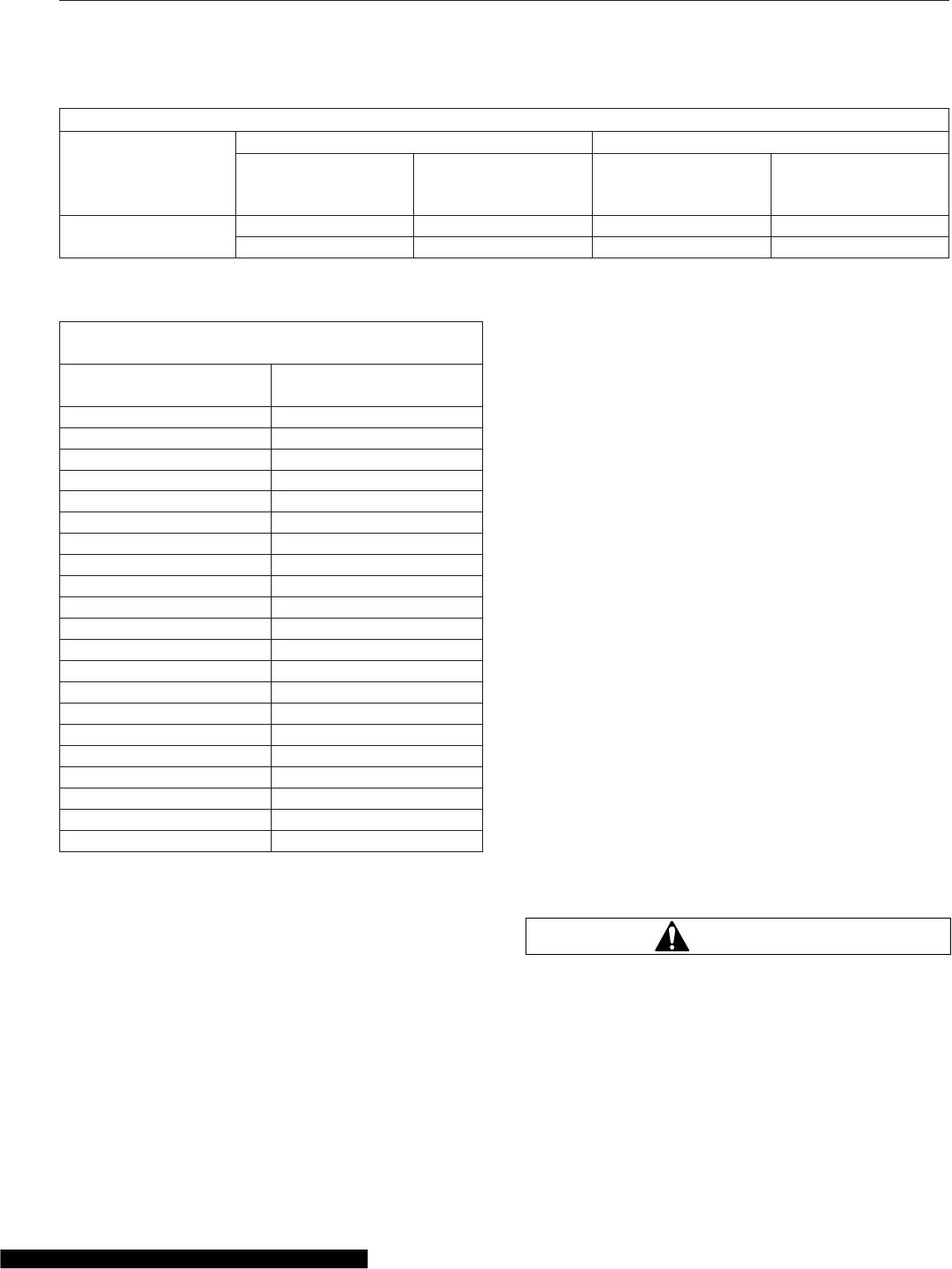
Parked HVAC Comfort Guide
Rest Hours Desired
Weather Setting Guide
Outdoor Temperature
Less Than or Equal
to: °F (°C)
Sunshine Less Than
or Equal to:
Maximum Blower
Speed
Minimum
Temperature Knob
Setting
12 90 (32) Night Time 6 10 O’clock
100 (38) Night Time 6 Mid
Table 8.1, Parked HVAC Comfort Guide
Temperature Control Knob Position to Requested
Output Temperature
Temperature Control
Knob Position (Clicks)
Requested Sleeper
Temperature: °F (°C)
1 60 (16)
2 60 (16)
3 62 (17)
4 64 (18)
5 66 (19)
6 68 (20)
7 70 (21)
8 71 (22)
9 72 (22)
10 73 (23)
11 74 (23)
12 75 (24)
13 76 (24)
14 77 (25)
15 78 (25)
16 79 (26)
17 80 (27)
18 82 (38)
19 84 (29)
20 85 (29)
21 Full Hot
Table 8.2, Temperature Control Knob Position to
Requested Output Temperature
Vehicles with Detroit Diesel Optimized
Idle
If a Cascadia vehicle is equipped with Detroit Diesel
optimized idle (O/I), it will affect the way the
ParkSmart operates. When the driver initiates the
O/I, the ParkSmart will operate in O/I mode as fol-
lows.
•The ParkSmart runs unless the ParkSmart fan
speed control knob is turned to the "OFF" posi-
tion. See Fig. 8.6. The fan speed control knob
must be set at "1" or higher.
•The engine will periodically start and run for at
least two hours to maintain battery voltage
then shut off. The ParkSmart will continue to
operate during this time.
•If the O/I shuts down due to a fault in the O/I
system, the ParkSmart will continue to operate
until it is shut off by the driver or one of the
automated failsafes.
•The ParkSmart ON/OFF button and LED indi-
cator on the parked HVAC control module do
not function when the vehicle is in O/I mode.
When the vehicle is not in O/I mode, the
ParkSmart ON/OFF button and LED indicator
operate normally.
All other functions are the same as the standard sys-
tem.
Accessory Heaters
Optional accessary heaters are available from the
factory in several configurations. Familiarize yourself
with the equipment on your specific vehicle, and fol-
low the manufacturer’s operating and maintenance
instructions.
WARNING
Do not operate fuel-operated heaters in an area
where flammable vapors, including gasoline or
diesel fumes, are present, such as at filling sta-
tions and tank farms. Turn off a fuel-operated
heater and allow it shut down completely before
entering an area where flammable gases or liq-
uids are present. Heaters continue to operate for
up to three minutes after being turned off.
Climate Control
8.5
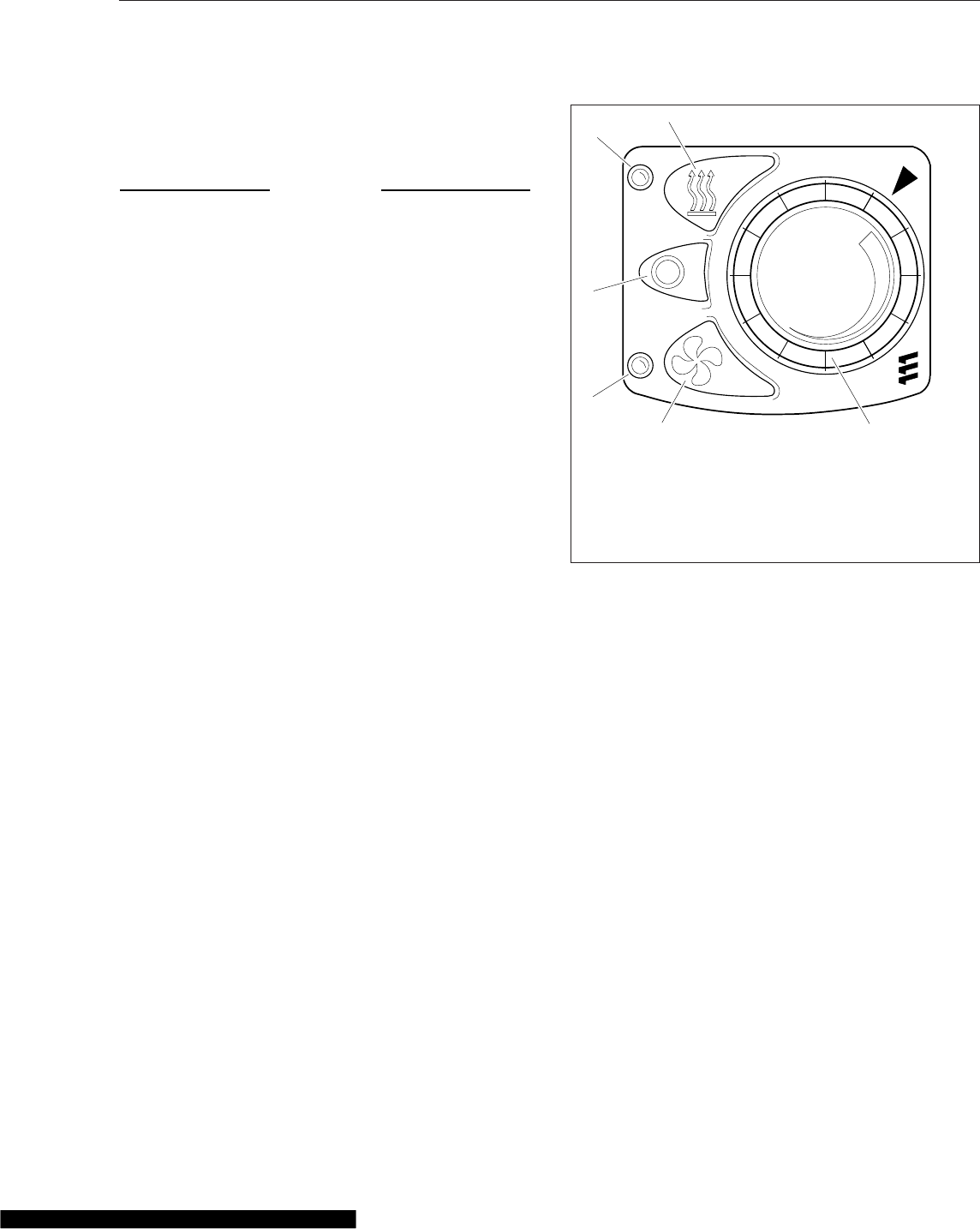
Failure to observe these precautions could cause
an explosion or fire, resulting in serious property
damage, and personal injury or death.
NOTICE
Always ensure that air inlet and outlet grilles are
not restricted. Restriction of any air inlet or outlet
ports could result in damage to the auxiliary
heater.
IMPORTANT: To maintain reliable performance,
run the accessory heater for at least 15 minutes
every month to prevent fuel from degrading.
Accessory heaters function when the ignition switch
is in the off position and the cab load disconnect
switch is on, if equipped.
IMPORTANT: Wait three minutes after shutting
down an accessory heater before turning the
cab load disconnect switch (CLDS) to OFF.
NOTE: The low voltage disconnect (LVD) control
prevents a heater from draining the batteries
below starting voltage.
Espar Heater
Refer to the Espar website, www.espar.com, for ad-
ditional information.
Espar Mini-Controller
To turn the heat on, press the heat button. See
Fig. 8.7. The red indicator will illuminate when heat
mode is activated. Adjust the desired temperature
with the control knob; rotate the temperature control
knob clockwise for warmer air, or counterclockwise
for cooler air. To turn the heat off, press the off but-
ton.
To turn the fan on, press the fan button. The blue
indicator will illuminate when ventilation mode is acti-
vated. To turn the fan off, press the off button.
Espar Digi-Controller
Vehicles built after December 8, 2011 with the Digi-
Controller and D2 air heaters are equipped with an
internal LVD in the Digi-Controller that prevents the
heater from draining battery voltage below 12.0 volts.
To turn heat mode on, press the heat button and the
heater will begin its start-up cycle. See Fig. 8.8.ON
will display briefly followed by the ambient tempera-
ture, and the green indicator will illuminate. Ambient
display temperature range is 41°F to 90°F.
To adjust the desired temperature, press the up or
down arrow buttons. The desired temperature will
display briefly, followed by the ambient temperature.
The desired temperature will remain in the modulator
memory when the heater is not in operation. Tem-
perature adjustment range is from 41°F to 90°F.
To turn heat mode off, press the heat button again.
The heater will initiate a 3-minute cooling cycle.
To turn the fan on, press and hold the fan button until
the blue indicator illuminates and the display shows
active rotating digits. To turn the fan off, press the
fan button again.
NOTE: The Digi-Controller also has a program-
mable run timer that will automatically shut the
heater off after the set time limit. The default
time limit setting is 10 hours.
02/06/2012 f611161
1
2
3
4
5
6
1. Temperature Control Knob
2. Fan Button
3. Fan Indicator (blue)
4. Off Button
5. Heat Indicator (red)
6 Heat Button
Fig. 8.7, Espar Mini-Controller
Climate Control
8.6
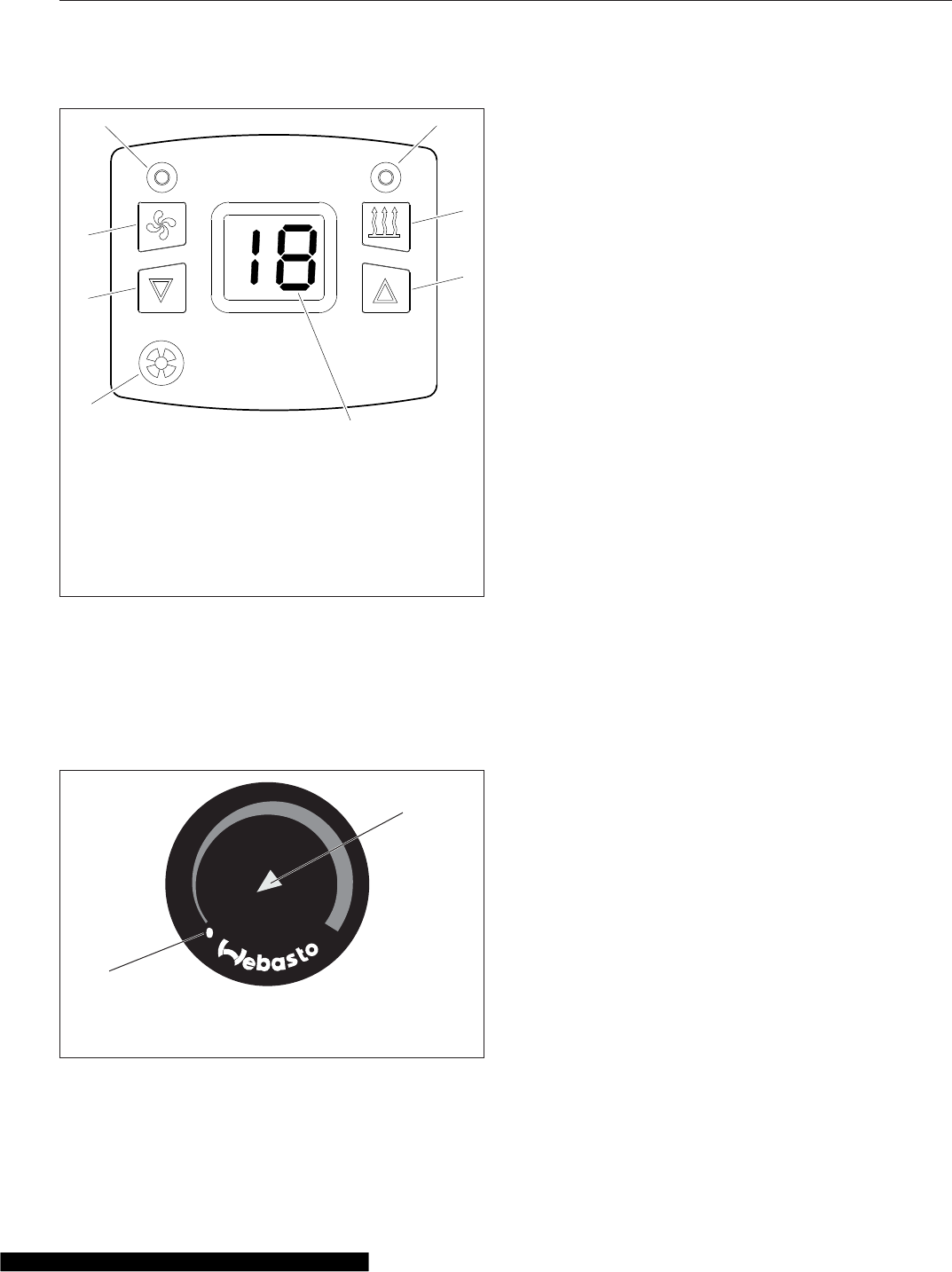
Webasto Heater
To turn the heater on, rotate the heater control knob
clockwise until the indicator light illuminates. See
Fig. 8.9. The Webasto heater requires one to two
minutes to warm up before warm air is delivered.
To set the desired temperature, rotate the heater
control knob clockwise for warmer air, or counter-
clockwise for cooler air.
To turn the heater off, rotate the heater control coun-
terclockwise until it clicks and the indicator light is
extinguished. The heater will initiate a two-minute
cooling cycle.
Refer to the Webasto website, techwebasto.com,
for additional information.
02/06/2012 f611160
Espar
8
1
2
3
45
6
7
1. Ambient Temperature Sensor
2. Down Arrow Button
3. Fan Button
4. Fan Indicator (blue)
5. Heat Indicator (green)
6 Heat On/Off Button
7. Up Arrow Button
8. Ambient Temperature Display
Fig. 8.8, Espar Digi-Controller
10/24/2014 f611162
1
2
1. Off Position
2. Heater On Indicator Light
Fig. 8.9, Webasto Heater Control Knob
Climate Control
8.7

9
Cab Features
Windows ........................................................................ 9.1
Mirrors .......................................................................... 9.1
Cab Amenities ................................................................... 9.1
Sleeper Amenities ................................................................. 9.2
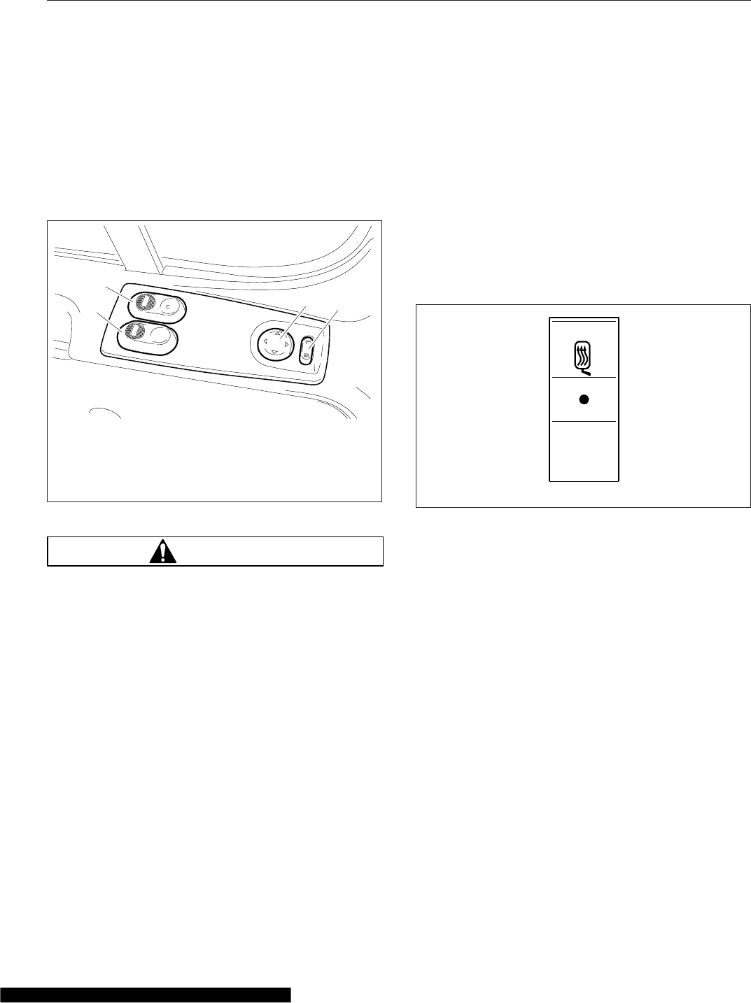
Windows
Power windows are standard on Cascadia™vehicles.
The driver’s door has two switches mounted in the
top of the door, that control the driver and passenger
windows separately. See Fig. 9.1. The passenger
door has a switch mounted in the top of the door that
controls the passenger-side power window.
WARNING
There is no anti-pinch protection when the win-
dow is almost closed. Be sure to clear all objects
from the window before closing.
The window switches have three positions: lower
window, neutral, and raise window. Press forward on
the switch to lower the window. Hold the switch down
in the forward position for approximately one second
to activate the express function; the window will con-
tinue to roll down after the switch is released. Press
the switch in the rearward position (bump) to raise
the window.
Mirrors
The standard outside mirrors are mounted on the
door frame. The power mirrors are controlled with a
left-hand or right-hand mirror selector switch, and a
directional switch. Select the left (driver) mirror, or
the right (passenger) mirror using the selector switch.
The mirror can then be adjusted by pressing the di-
rectional switch arrow for the direction the mirror
should be adjusted.
The outside door mirrors can be heated to keep
them clear of fog, frost, and ice. To heat the mirrors,
press the upper part of the mirror heat switch on the
dash. See Fig. 9.2. When the mirror heat switch is
on, an amber indicator light illuminates inside the
switch. If the vehicle has Optimized Idle, mirror heat-
ing will not operate with the key in accessory mode,
or if the Optimized Idle feature turns mirror heating
off to reduce stress on the batteries. Refer to Chap-
ter 11 for more information.
Cab Amenities
Cascadia vehicles are available with many optional
features. The following are some of those options.
Cup Holders
Two cup holders and a storage tray are molded into
the center dash. See Fig. 9.3.
Lighting
See Chapter 5 for detailed information regarding
lighting controls.
Power Outlets
Power outlets that supply 12V power for accessories
are located on either side of the cup holders. An op-
tional ashtray/coin holder may be located in the cen-
ter dash. See Fig. 9.3.
06/13/2007 f602318
1
2
34
1. Passenger-Side Window Switch
2. Driver-Side Window Switch
3. Mirror Directional Switch
4. Left-Hand or Right-Hand Mirror Selector Switch
Fig. 9.1, Door Switches (driver-side shown)
MIRR
HEAT
f61090402/26/2007
Fig. 9.2, Mirror Heat Switch
Cab Features
9.1
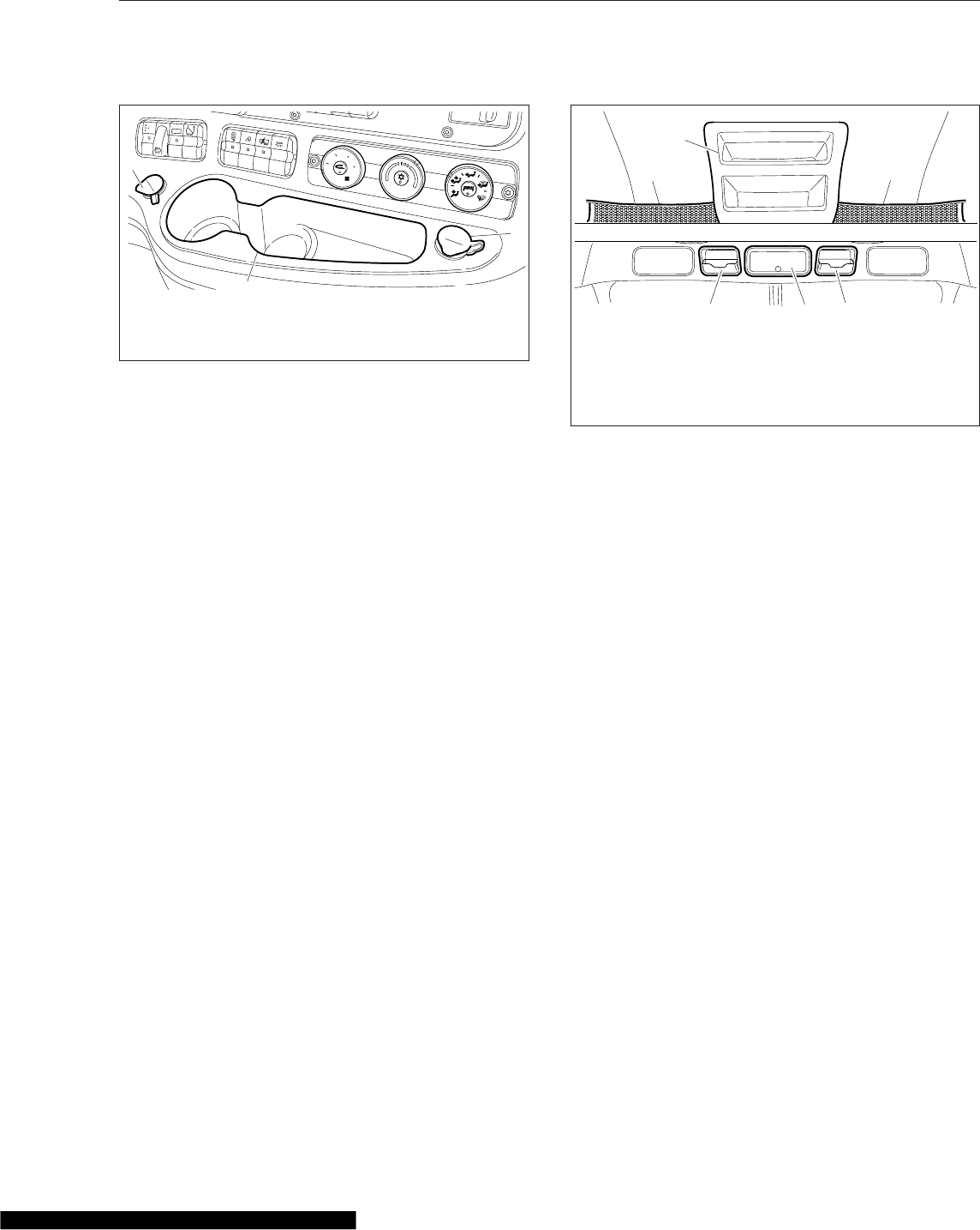
Radio and CB
The radio and CB are typically installed in the over-
head console. An optional hot mount may be in-
stalled on the dash for fleet CB radios.
Storage
Storage compartments/grab handles are molded into
the lower portion of the driver and passenger doors.
The glove box is located in front of the passenger
seat. To lock the latch, insert the key in the lock, and
turn it 1/2-turn clockwise. Remove the key. To unlock
the latch, insert the key in the lock, and turn it 1/2-
turn counterclockwise. The glove box door is hinged
at the bottom. To open the unlocked door, push the
button in with your thumb and pull gently on the
tang-style latch. The door will swing downwards, then
stop in the open position. To close the door, swing it
upwards, and put gentle pressure on the latch. The
door will be secured, but not locked.
Storage pockets are located in the overhead console,
above the driver and passenger seats. A glove box is
located in the center of the overhead console. See
Fig. 9.4.
Sleeper Amenities
Cascadia sleepers are available with many optional
features. The following are some of those options.
NOTE: See Chapter 8 for detailed information
regarding sleeper climate controls.
Baggage Compartment Doors
The baggage compartment doors are intended as a
convenient means to stow or remove items under the
bunk. The baggage compartment doors can be
opened using the pull cable located near the aft edge
of the cab door opening on the sidewall behind the
seat. Pull the cable handle labeled BAGGAGE for-
ward to open the door.
IMPORTANT: The baggage compartment doors
are two-stage latching. When closing the doors,
ensure that they are completely latched to pre-
vent wind noise and water intrusion.
Lighting
See Chapter 5 for detailed information regarding
lighting controls.
Power Outlets
Power outlets are located underneath the lower
bunk.
Sleeper Access Door
The sleeper access door is not intended for entry or
exit. The door is intended only as a convenient
means to stow or remove personal belongings in the
sleeper area. The sleeper access door can be
opened using two different methods. The primary
method is the pull cable located near the lower rear
edge of the cab door opening on the sidewall behind
ENG
SHDN
ATC
ENG
BRK
MIRR
HEAT
UTLY
LAMP DOME
HI
LO
0
24
8
6
POWER
OUTLET
12V−10A
IS IN MOTION
SUSP
AIR
LOWER
AUTO
POWER
OUTLET
12V−10A
TRLR
AUX
OVRD
TC
06/14/2007 f610950a
2
1
1
1. Power Outlets
2. Cup Holders and Storage Tray
Fig. 9.3, Center Dash
02/25/2014 f602319a
11
2
33
4
1. Cargo Storage with Netting
2. Overhead Storage Compartment
3. Storage Pocket
4. Glove Box
Fig. 9.4, Overhead Storage
Cab Features
9.2

the seat. Pull the cable handle labeled ACCESS for-
ward to open the sleeper door. The secondary
method is the black knob located at the upper rear
edge of the sleeper door opening. Pull the knob
down to open the sleeper door.
IMPORTANT: The sleeper access doors are
two-stage latching. When closing the doors, en-
sure that they are completely latched to prevent
wind noise and water intrusion.
Sliding Side Window
The lower section of the sliding side window moves
vertically and may be locked in multiple positions to
suit. Two spring-loaded tabs are located at the top of
the sliding section. To adjust the window, pull both
tabs toward the center of the glass and move the
sliding section to the desired height. Release the
tabs to lock the sliding section.
Cab Features
9.3

10
Engine Starting, Operation,
and Shutdown
Engine Starting .................................................................. 10.1
Engine Operation ................................................................ 10.2
Engine Shutdown ................................................................ 10.4
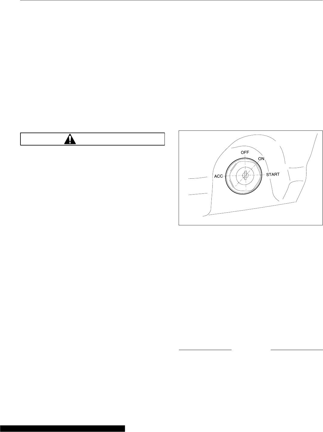
Engine Starting
This engine chapter is to serve as a guide for best
practices only. Each engine model may have operat-
ing characteristics that are unique to that particular
engine, and will be documented in the engine manu-
facturer’s literature. Always refer to specific instruc-
tions and recommendations from the engine manu-
facturer.
NOTE: Before starting the engine, read Chap-
ter 4,Instruments,and Chapter 5,Driver
Controls. Read the engine manufacturer’s oper-
ating instructions before starting the engine.
WARNING
Never pour fuel or other flammable liquid into the
air inlet opening in the air intake in an attempt to
start the vehicle. This could result in a flash fire
causing serious personal injury or property
damage.
IMPORTANT: Cascadia vehicles are equipped
with starter interlocks to enhance reliability and
safety. Anti-grinding, starter pinion, and thermal
protection logic limit the amount of time and
conditions for starter engagement. Cranking
may be limited from 5 to 15 seconds, with a 30-
second cool-down period, as determined by the
protection logic. If the engine is turning, the
starter will not engage. Depending on the trans-
mission option, the starter will not engage if the
clutch is not fully depressed, or if the transmis-
sion is not in neutral.
IMPORTANT: The starter can not be used for
priming the fuel system. If the fuel/water separa-
tor filter is replaced, and the fuel system needs
to be primed, see the engine manufacturer’s
operating instructions.
1. Before engine start-up, complete the pre- and
post-trip inspections and maintenance proce-
dures in Chapter 21.
2. Set the parking brake.
3. Place the transmission in neutral. On vehicles
with manual transmissions, fully depress the
clutch pedal.
NOTE: Depending on local jurisdictional emis-
sions regulations, vehicles and/or engines that
are domiciled outside of the U.S. and Canada
may not be equipped with the WAIT TO START
or START BLOCKED lamp.
4. Turn the ignition switch to the ON position and
allow the gauge sweep to complete. See
Fig. 10.1. The audible alert will sound for ap-
proximately four seconds.
During cold conditions, the WAIT TO START
lamp may illuminate. Wait until the lamp goes out
before turning the ignition key to START.
NOTE: The length of time the WAIT TO START
lamp remains illuminated depends on the ambi-
ent temperature. The lower the ambient tem-
perature, the longer the lamp will be illuminated.
NOTE: If the ignition switch is turned to START
before the gauge sweep has completed or if the
starter has overheated, the START BLOCKED
lamp may illuminate. Turn the ignition switch
back to ON, wait for the lamp to go out, then
turn the ignition switch to START again.
5. Once the gauge sweep has completed, turn the
ignition key to the START position. Release the
key the moment the engine starts.
NOTICE
Do not rev the engine if the oil pressure gauge
indicates no oil pressure. Shut down the engine
07/19/2006 f610805
Fig. 10.1, Ignition Switch
Engine Starting, Operation, and Shutdown
10.1

if oil pressure does not build within approxi-
mately ten seconds. Check to determine the
cause of the problem. Operating the engine with
no oil pressure will damage the engine.
6. It is not necessary to idle the engine before en-
gaging or starting the operation, but load should
be applied gradually during the warm-up period
until the oil temperature reaches 140°F (60°C).
7. Apply load gradually during the warm-up period.
NOTICE
If the oil pressure gauge indicates no oil pres-
sure, shut down the engine within approximately
ten seconds to avoid engine damage.
8. Check the oil pressure gauge for any drop in lu-
bricating oil pressure or mechanical malfunction
in the lubricating oil system. Minimum oil pres-
sure at idle is 7 psi (50 kPa).
Cold-Weather Starting
See the engine manufacturer’s operation manual for
starting aids that are approved for specific engines.
Starting After Extended Shutdown
Before engine start-up, complete the engine pretrip
inspections in Chapter 21.
NOTICE
Failure to eliminate water-diluted lubricating oil
may lead to serious engine damage at startup.
An engine in storage for an extended period of time
(over winter, for example) may accumulate water in
the oil pan through normal condensation of moisture
on the internal surfaces of the engine. Oil diluted by
water cannot provide adequate bearing protection at
start-up. For this reason, change the engine oil and
filters after extended storage.
Engine Operation
Safety and Environmental
Considerations
WARNING
Do not operate the engine in an area where flam-
mable vapors such as gasoline or diesel fumes
are present. Shut off the engine when in an area
where flammable liquids or gases are being
handled. Failure to observe these precautions
could result in serious injury or death.
All engines on Freightliner vehicles comply with the
requirements of the Federal (U.S.) Clean Air Act.
Once an engine is placed in service, the responsibil-
ity for meeting both state and local regulations is with
the owner/operator.
IMPORTANT: Depending upon local jurisdic-
tional emissions guidelines, vehicles that are
domiciled outside of the U.S. and Canada may
not have engines and/or emissions aftertreat-
ment systems that are compliant with EPA07,
EPA10, or GHG14 regulations.
NOTICE
It is extremely important that the following guide-
lines be followed for engines that comply with
EPA07 or newer regulations, or damage may
occur to the aftertreatment device, and the war-
ranty may be compromised.
•Use ultralow-sulfur diesel with 15 ppm sul-
fur content or less.
•Do not use fuel blended with used engine
lube oil or kerosene.
•Use only engine lube oil with a sulfated ash
level less than 1.0 wt%; currently referred
to as CJ-4 oil.
Adequate maintenance of the engine and the diesel
particulate filter (DPF) are the responsibility of the
owner/operator, and are essential to keep the emis-
sion levels low. Good operating practices, regular
maintenance, and correct adjustments are factors
that will help keep emissions within the regulations.
The driver should be familiar with the vehicle warning
system in order to bring the vehicle to a safe stop if
Engine Starting, Operation, and Shutdown
10.2
the engine malfunctions. If the driver doesn’t under-
stand how the warning system works, an engine
shutdown could occur, causing a safety hazard. See
Chapter 11 for more information.
Engine Break-In
Each engine must pass a full-load operating test on
a dynamometer before shipment, thereby eliminating
the need for a break-in. Before running the engine
for the first time, follow the instructions in the manu-
facturer’s engine operation manual.
Normal Operation
WARNING
Do not operate the engine in an area where flam-
mable vapors such as gasoline or diesel fumes
are present. Shut off the engine when in an area
where flammable liquids or gases are being
handled. Failure to observe these precautions
could result in serious injury or death.
Every engine has an operating range in which it per-
forms most efficiently. The operating range extends
from maximum torque rpm at the low end, to engine
rated speed at the high end. Most engines deliver
best fuel economy when operated in the low- and
mid-speed segments of the efficiency range and pro-
duce maximum horsepower at rated speed, which is
also the recommended maximum speed of the en-
gine. For further engine-specific information, refer to
the engine manufacturer’s operation manual.
Prolonged idling of engines is not recommended, and
is illegal in some states. Idling produces sulfuric acid
that is absorbed by the lubricating oil, and eats into
bearings, rings, valve stems, and engine surfaces. If
you must idle the engine for cab heating or cooling,
use the high idle function of the cruise control
switches. An idle speed of 900 rpm should be
enough to provide cab heat in ambient temperatures
that are above freezing.
If the engine is programmed with an idle shutdown
timer, 90 seconds before the preset shutdown time,
the CHECK engine light will begin to flash at a rapid
rate. If the position of the clutch pedal or service
brake changes during this final 90 seconds the idle
shutdown timer will be disabled until reset.
Cold-Weather Operation
Satisfactory performance of a diesel engine operating
in low ambient temperatures requires modification of
the engine, surrounding equipment, operating prac-
tices, and maintenance procedures. The lower the
temperature, the greater the amount of modification
required. For service products approved for use in
cold weather for your engine, see the engine manu-
facturer’s engine operation manual.
If satisfactory engine temperature is not maintained,
maintenance costs will increase due to greater en-
gine wear. If the engine coolant gets too cold, raw
fuel will wash the lubricating oil off the cylinder walls
and dilute the crankcase oil, causing all moving parts
of the engine to suffer from poor lubrication.
If the engine is in good mechanical condition and the
precautions necessary for cold-weather operation are
taken, ordinary cold weather will not cause difficulty
in starting or loss of efficiency.
The following points are important to observe when
operating in cold weather.
•Check for cracks in the battery cases, for cor-
rosion of the terminals, and for tightness of the
cable clamps at the terminals.
•Charge the batteries to full capacity. Replace
damaged batteries.
•If equipped, turn off the load disconnect switch
after the engine is shut down to prevent battery
discharge.
•Have the alternator output checked at an au-
thorized Freightliner service provider.
•Check the condition and tension of the drive
belts.
•Refer to the engine manufacturer’s operation
manual for recommended heaters, low-
viscosity lubricating oils, winter-grade fuels,
and approved coolants.
•Periodically check the coolant mixing ratio
(concentration of antifreeze in the coolant). Add
more if necessary.
•At outside temperatures below -4°F (-20°C), a
coolant preheater is recommended.
Engine Starting, Operation, and Shutdown
10.3

NOTICE
For Detroit engines (EPA07 and newer), use of a
winterfront is not recommended, as it can cause
false fault codes with the engine and aftertreat-
ment system, and possible emission component
failures.
If using a winterfront, leave at least 25% of the grille
opening exposed in sectioned stripes that run per-
pendicular to the charge-air-cooler tube-flow direc-
tion. This assures even cooling across each tube,
and reduces header-to-tube stress, and possible
chance of component failure. For engine-specific
guidelines, see below:
Cummins and Mercedes-Benz engines: A winterfront
may be used to improve cab heating while idling, and
only when the ambient temperature remains below
10°F (-12°C).
Detroit engines (EPA07 and newer): Use of a winter-
front is not recommended. Using a winterfront can
cause excessive fan run time, increased fuel con-
sumption, and failure of the DEF system heaters to
operate correctly, resulting in fault codes, poor per-
formance, and power reduction. A winterfront should
only be used temporarily in the following situations:
•To improve cab heating while idling in an ex-
tremely cold ambient temperature;
•When the ambient temperature remains below
-22°F (-30°C) and the engine is unable to
maintain a running coolant temperature of
175°F (80°C) during normal over-the-road
operation.
High-Altitude Operation
Engines lose horsepower when operated at high alti-
tude because the air is too thin to burn as much fuel
as at sea level. This loss equals about three percent
for each 1000 ft (300 m) altitude above sea level for
a naturally aspirated engine.
All engines used on Freightliner vehicles are altitude-
compensated by the use of a turbocharger. This re-
duces smoky exhaust at high altitudes, requires less
downshifting, and allows the engine to make better
use of its fuel. Nevertheless, shift gears as needed to
avoid excessive exhaust smoke.
Engine Shutdown
1. With the vehicle stopped, set the parking brake
and place the transmission in neutral.
NOTICE
Idle the engine one to two minutes before shut-
ting it down. After hard operation, shutting down
the engine without idling may cause damage to
the turbocharger.
2. Allow the engine to idle one to two minutes be-
fore shutting it down. This allows the lubricating
oil and the coolant to carry heat away from the
combustion chambers, bearings, shafts, and
seals.
NOTICE
Except in an emergency, do not shut down the
engine when the coolant temperature is above
194°F (90°C). To do so could damage the engine.
3. Turn off the ignition switch and shut down the
engine.
Engine Starting, Operation, and Shutdown
10.4

11
Optional Engine Systems
Engine Protection—Warning and Shutdown ........................................... 11.1
Engine Idle Limiting .............................................................. 11.2
Power Takeoff (PTO) Governor ..................................................... 11.2
Optimized Idle® ................................................................. 11.2
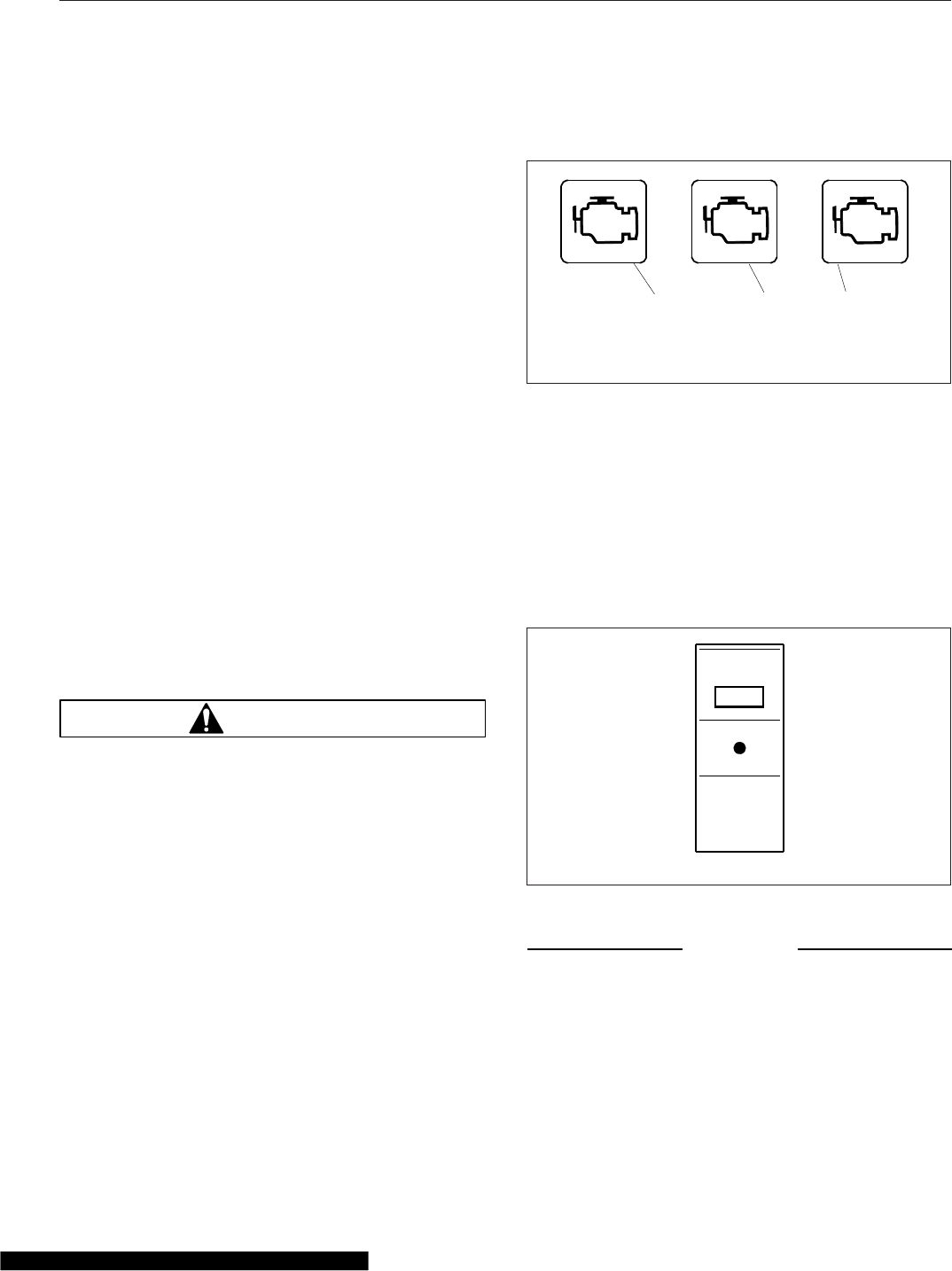
Engine Protection—Warning
and Shutdown
NOTE: The engine warning and shutdown sys-
tem is present on EPA07-compliant and newer
vehicles.
The driver should be familiar with the vehicle warning
system in order to bring the vehicle to a safe stop if
necessary. If the driver doesn’t understand how the
warning system works, the driver may not be able to
utilize the advantage of the advance warning system
to pull over appropriately.
The engine will begin a warning and derate and/or
shutdown process if the engine coolant temperature,
coolant level, engine oil pressure, or exhaust after-
treatment system (ATS) reach preset levels. On
some engines, the warning process will begin when
the engine oil temperature, engine coolant tempera-
ture, or the intake air temperature reach preset lev-
els. Detroit™engines may also begin the warning
and shutdown process if water is detected in the fuel.
See the engine manufacturer’s operation manual for
specific details for your vehicle. See Chapter 12 for
the warning and shutdown modes associated with
the ATS.
Electronic engine protection can be specified as ei-
ther SHUTDOWN or WARNING and DERATE.
WARNING
When the STOP engine or CHECK engine lamp
illuminates, most engines are programmed to
shut down automatically within 30 seconds. The
driver must immediately move the vehicle to a
safe location at the side of the road to prevent
causing a hazardous situation that could cause
bodily injury, property damage, or severe damage
to the engine.
In SHUTDOWN mode, the red STOP engine lamp
will illuminate when the problem is serious enough to
reduce power or speed. See Fig. 11.1. Engine power
will ramp down, then the engine will shut down if the
problem continues while in derate mode. The driver
has 30 or 60 seconds (depending on the critical fault
type) after the STOP engine lamp illuminates to
move the vehicle safely off the road. If the vehicle
cannot be moved to a safe location within that time,
turn the ignition switch to OFF for at least five sec-
onds, then restart the engine. Repeat this action until
the vehicle is safely off the road.
Do not operate the vehicle further until the problem
causing the shutdown has been corrected.
Some vehicles may have a shutdown override
switch, which can be used to momentarily override
the shutdown sequence. This switch resets the shut-
down timer, restoring power to the level before the
derate. The switch must be pressed again after five
seconds to obtain a subsequent override. See
Fig. 11.2.
NOTICE
When the derate process begins, immediately get
the vehicle serviced in order to prevent severe
damage to the engine.
Detroit engines may begin a warning and derate pro-
cess if water is detected in the fuel, or for high en-
gine coolant temperature. In WARNING and DER-
ATE mode, the CHECK engine, STOP engine, or MIL
07/09/2009 f611036
123
CHECK STOP
1. Malfunction Indicator Lamp (MIL)
2. CHECK Engine Lamp
3. STOP Engine Lamp
Fig. 11.1, Engine Warning Lamps
ENG
SHDN
f61090002/26/2007
OVRD
Fig. 11.2, Shutdown Override Switch
Optional Engine Systems
11.1

lamp will illuminate to indicate an engine problem
that requires service and the engine controls will
begin a derate of engine output. Continuing to run
the engine while it is in derate mode could cause
severe damage to the engine.
Engine Idle Limiting
Idle Shutdown Timer
This feature is an optional 1- to 100-minute idle shut-
down system. Its purpose is to conserve fuel by
eliminating excessive idling, and allowing a turbo-
charger cool-down period. Idle shutdown timing and
parameters are programmable. See the engine
manufacturer’s operation manual for specific details
for your vehicle.
The idle shutdown system requires that the transmis-
sion be in neutral with the parking brake set.
California Engine Idle Limiting
In order to meet the California Air Resources Board
(CARB) engine idle limit, vehicles are equipped with
an engine idle shutdown feature. The automatic shut-
down feature is required on all California-certified
engines (with the exception of engines used in spe-
cific vehicle types that are exempt from the require-
ment). Owners that wish to have the shutdown fea-
ture disabled on vehicles operating in California
should consult with California authorities to determine
if their vehicle qualifies for the exemption.
When the CARB engine idle limiting feature is en-
abled, the engine will typically shut down after five
minutes of continuous idling with the transmission in
neutral or park, and the parking brake set. It will also
shut down after 15 minutes with the transmission in
neutral or park, and the parking brake off. See the
engine manufacturer’s operation manual for specific
details for your vehicle.
Changing the position of the brake pedal, clutch
pedal, accelerator pedal, shutdown override switch,
or parking brake during the final 30 seconds will
cause the shutdown timer to reset. After an auto-
matic shutdown, the engine may be restarted and
operated normally.
Power Takeoff (PTO) Governor
WARNING
To avoid injury, do not install a PTO that is not
Detroit Diesel approved onto a Detroit™Trans-
mission. Use of a non-Detroit Diesel approved
PTO with a Detroit Transmission could result in
unintended operation which could lead to severe
personal injury.
Engine power takeoffs (PTO) tap into engine power
to run auxiliary devices, such as hydraulic pumps
that power additional equipment. The following are
general guidelines for operating a PTO.
1. Set the parking brake and put the transmission in
neutral.
2. Press the dash PTO switch. Release the switch
when the light begins to blink.
When the light illuminates steadily, the PTO is
engaged and ready to operate. In stationary
mode, the vehicle must remain in neutral with the
parking brake set.
3. To activate mobile mode, shift from neutral to
reverse, 1st, or 2nd gear. The clutch will open
and the PTO will disengage for a moment.
4. Touch the accelerator pedal to close the clutch
and engage the PTO in mobile mode. The PTO
may be operated with the transmission in neutral
or reverse, and 1st and 2nd gears only.
NOTE: Do not attempt to change gears while
the vehicle is moving. The transmission will ig-
nore the request.
5. To deactivate mobile mode, bring the vehicle to a
stop. The clutch will open and shut down power
to the PTO.
6. To resume stationary mode, shift to neutral. The
PTO will engage.
7. To deactivate PTO, press the PTO switch again.
When the light in the switch goes out, power to
the PTO is shut off.
Optimized Idle®
Optimized Idle reduces engine idle time by running
the engine only when required. Optimized Idle auto-
matically shuts down and restarts the engine as
Optional Engine Systems
11.2
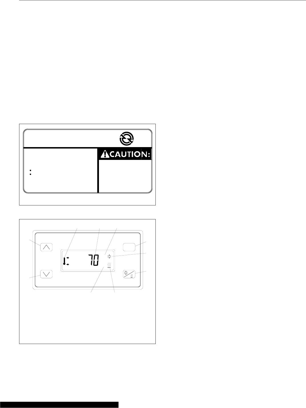
needed to ensure engine oil temperature remains
within factory preset limits, the batteries stay
charged, and cab/sleeper temperature remains at the
thermostat setting. The benefits of the system in-
clude reduced engine idle time, fuel savings, reduc-
tion of exhaust emissions and noise, increased
starter and engine life, and reduced chance of dead
batteries.
Vehicles equipped with Optimized Idle have a label
on the dash, and a telltale (OPT IDLE) in the ICU.
See Fig. 11.3 for the dash label detail. If equipped, a
thermostat is located above the sleeper bunk. See
Fig. 11.4.
Optimized Idle operates in two modes:
•Engine mode: Keeps the battery charged and
engine oil temperature between 60 and 104°F
(16 to 40°C).
•Thermostat mode (activated when the optional
thermostat is turned on): Keeps the cab and
sleeper at a constant preset temperature, in
addition to all functions available in engine
mode.
Thermostat mode controls the set point, which is the
desired temperature of the cab and sleeper, and the
comfort zone, which is the allowed temperature de-
viation from the set point before the engine starts.
The thermostat display defaults to show the tempera-
ture of the sleeper, but changes accordingly as the
buttons are pressed.
The button functions are as follows:
•Up arrow: Increases the set point and comfort
zone (allowed temperature variation).
•Down arrow: Decreases the set point and com-
fort zone.
•Cool/Heat: Sets either cooling or heating op-
eration.
•MODE: Scrolls through the various functions. It
can also be used to set desired temperature
values.
If a vehicle has Optimized Idle, the following func-
tions will not operate with the key in accessory
mode. Optimized Idle may also turn these functions
off to reduce stress on the batteries.
•Cab climate control fan
•Sleeper climate control fan
•Mirror heat
•Fuel/water separator heat
•Seat heat
•Advertising light
•Auxiliary circulation fan (windshield)
•Air dryer
1. To activate Optimized Idle (engine mode):
1.1 Set the parking brake.
1.2 If it is open, close and secure the hood.
11/13/96 f080062
TO AVOID
UNINTENTIONAL
VEHICLE MOVEMENT,
DO NOT MOVE SHIFT
LEVER OR RANGE
SELECTOR WHEN
OPTIMIZED IDLE IS ON
OPTIMIZED IDLETM
TO USE:
− IDLE ENGINE
− CLOSE HOOD
− ENGAGE PARKING BRAKES
− PUT TRANSMISSION IN
NEUTRAL AND
HI RANGE (IF EQUIPPED)
− THEN, MOVE CRUISE SWITCH
FROM OFF TO ON
− IF DESIRED, TURN CAB
THERMOSTAT ON (IF EQUIPPED)
Fig. 11.3, Optimized Idle Dash Label
MODE
°F
°C
11/08/96
1
2
3 4 5
6
7
8
9
10 f601250
1. Down Arrow Button
2. Up Arrow Button
3. Upper/Lower
Temperature Icon
4. Temperature Display
5. Degrees Fahrenheit
Indicator
6. MODE Button
7. Cooling Icon
8. Cool/Heat Selection
Button
9. Heating Icon
10. Degrees Celsius
Indicator
Fig. 11.4, Optimized Idle Thermostat
Optional Engine Systems
11.3

1.3 Start the engine and let it idle.
1.4 Put the transmission in neutral.
1.5 Turn on the cruise control.
The OPT IDLE lamp will blink, indicating
that Optimized Idle is active. The system
is now in engine mode and after an initial
phase, in which the idle speeds up to
1000 rpm, the engine will stop and start
automatically to keep the battery charged
and the engine oil warm.
IMPORTANT: The cruise control must be
turned on once the engine is idling. If it was
previously turned on, turn the cruise control
off, then turn it on again.
2. Activate thermostat mode, if equipped.
NOTE: When the system is in thermostat
mode, it is also in engine mode. It will con-
tinue to operate in engine mode even if ther-
mostat mode is turned off.
2.1 With the system in engine mode, set the
cab and sleeper heater or air conditioner
controls to the highest setting.
2.2 Turn on the thermostat by touching any of
the four buttons. See Fig. 11.4.
The display will flash the current sleeper
temperature and the previous mode (cool-
ing or heating) selected. If the cab needs
to be cooled or heated, the cool/heat icon
will flash.
2.3 Choose either cool or heat by pressing the
Cool/Heat button. Make sure the selection
matches that of the cab controls.
IMPORTANT: If the heat or cool selection of
the thermostat does not match that of the
cab controls, the system will idle and cycle
excessively.
2.4 Select Fahrenheit or Celsius by pressing
and holding the MODE button until either
the "F" or "C" is displayed.
2.5 Select the temperature set point by press-
ing the up or down arrows, as applicable.
Holding the button will cause the display
to scroll up or down rapidly. When the de-
sired set point is displayed, release the
button. The set point is stored in memory.
2.6 Select the temperature comfort zone by
pressing the MODE button until the upper
and lower temperature limit icon is dis-
played. Then use the up or down arrow to
select one of the three comfort zones: 4°F
(2°C), 7°F (4°C), or 10°F (6°C).
3. To deactivate thermostat mode and return to just
engine mode, press and hold the MODE button
for three seconds.
4. To shut down Optimized Idle completely, either
turn off the ignition or use the drive away feature.
The drive away feature allows the use of all the
engine features. Use the drive away feature as
follows:
4.1 If the engine is running: Release the park-
ing brakes or put the transmission in gear.
If the engine is not running: Start the en-
gine. Release the parking brakes or put
the transmission into gear.
4.2 Let the engine return to base idle. The
active light will turn off. Optimized Idle is
now disabled.
Optional Engine Systems
11.4

12
Emissions and Fuel Efficient
Components
Greenhouse Gas Emissions and Fuel Consumption Standards ........................... 12.1
EPA-Regulated Emissions Aftertreatment Systems ..................................... 12.1
Diesel Exhaust Fluid and Tank, EPA10 and Newer Engines .............................. 12.3

Greenhouse Gas Emissions
and Fuel Consumption
Standards
Vehicles and/or engines manufactured after Decem-
ber 31, 2006 and domiciled in the U.S. or Canada
are required to meet all EPA and NHTSA regulations
effective as of the vehicle build date. Engines manu-
factured between January 1, 2007 and December 31,
2009 meet EPA07 requirements. Engines manufac-
tured between January 1, 2010 and December 31,
2012 meet EPA10 requirements. Engines manufac-
tured from January 1, 2013 meet NHTSA and EPA
2014 fuel efficiency and greenhouse gas emission
standards (GHG14) requirements.
Model year 2013 and later vehicles meet additional
requirements as specified by GHG14 requirements.
These vehicles are equipped with components that
increase fuel efficiency and reduce GHG emissions.
Components may include, but are not limited to, low-
rolling resistance tires; aerodynamic devices such as
hood, cab/sleeper extenders, and fuel tank fairings;
vehicle speed limiter; and idle shutdown timer. If re-
placement of any drag-reducing component is re-
quired, the replacement component must meet or
exceed the drag reduction performance of the origi-
nally installed component in order to maintain compli-
ance with GHG14 requirements.
EPA-Regulated Emissions
Aftertreatment Systems
IMPORTANT: Depending on local jurisdictional
guidelines, vehicles that are domiciled outside of
the U.S. and Canada may not have emissions
aftertreatment systems (ATS) that are compliant
with EPA regulations.
NOTICE
Follow these guidelines for engines that comply
with EPA07 or newer regulations, or damage may
occur to the aftertreatment device (ATD) and the
warranty may be compromised.
•Use ultralow-sulfur diesel with 15 ppm sul-
fur content or less.
•Do not use fuel blended with used engine
lube oil or kerosene.
•Engine lube oil must have a sulfated ash
level less than 1.0 wt %; currently referred
to as CJ-4 oil.
IMPORTANT: Using non-specification fuels or
oils can lead to shortened diesel particulate filter
(DPF) cleaning or replacement intervals. For
example, using CJ-4+ oil with 1.3% sulfated ash
(30% more ash content) may result in the need
for DPF cleaning or replacement 20 to 30%
sooner than would normally be required.
IMPORTANT: See the engine manufacturer’s
operation manual for complete details and op-
eration of the ATS.
EPA07 Engines
Engines built between January 1, 2007 and Decem-
ber 31, 2009 are required to meet EPA07 guidelines
for reduced exhaust emissions of particulate matter
and nitrogen oxides (NOx). NOx is limited to just
over 1 gram per brake horsepower hour (g/bhp-hr),
and particulate matter cannot exceed 0.01 g/bhp-hr.
The EPA07 ATS varies according to engine manufac-
turer and vehicle configuration, but the exhaust muf-
fler is replaced by an aftertreatment device (ATD).
Inside the ATD, the exhaust first passes over the die-
sel oxidation catalyst (DOC), then passes through
the diesel particulate filter (DPF), which traps soot
particles. The soot is burned to ash during a process
called regeneration (regen).
EPA10 and Newer Engines
The EPA mandates that all engines built after De-
cember 31, 2009 must reduce the level of emissions
exhausted by the engine to the following levels:
•Nitrogen Oxides (NOx) – 0.2 g/bhp-hr
•Particulate Matter (PM) – .01 g/bhp-hr
To meet EPA guidelines, engines that are compliant
with EPA10 and newer regulations use an ATS that
has, in addition to a DOC/DPF device like that used
in an EPA07 ATD, a Selective Catalytic Reduction
(SCR) device to reduce NOx downstream of the en-
gine. After exhaust gases leave the DPF, a controlled
quantity of diesel exhaust fluid (DEF) is injected into
the exhaust stream. In the presence of heat, DEF is
converted to ammonia gas, which reacts with NOx in
the selective catalyst chamber to yield nitrogen and
water vapor, which exit through the tailpipe.
Emissions and Fuel Efficient Components
12.1
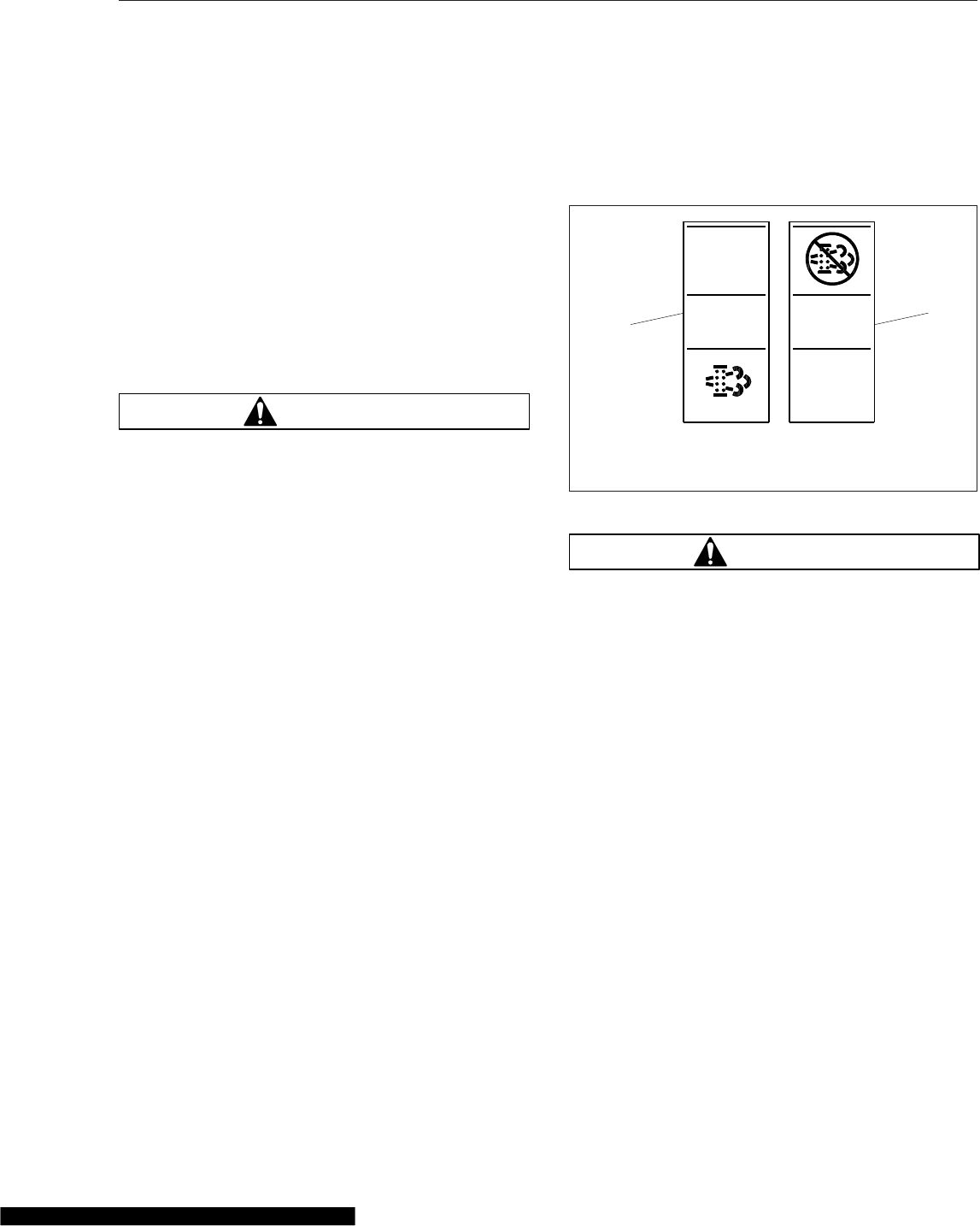
Regeneration
The harder an engine works, the better it disposes of
soot. If the exhaust temperature is high enough, a
process called passive regeneration (regen) occurs
as the vehicle is driven normally. However, if the en-
gine isn’t running hot enough, the electronic controls
may initiate an active regen, whereby extra fuel is
injected into the exhaust stream to superheat and
reduce the soot trapped in the DPF to ash. Active
regen happens only when the vehicle is moving
above a certain speed, determined by the engine
manufacturer. See your engine operation manual for
complete details. Both active and passive regen hap-
pen automatically, without driver input.
WARNING
Active regeneration can occur automatically any-
time the vehicle is moving. The exhaust gas tem-
perature could reach 1500°F (800°C), which is hot
enough to cause a fire, heat damage to objects
or materials, or personal injury to persons near
the exhaust outlet. The exhaust temperature can
remain high even after the vehicle has stopped.
When stopping the vehicle shortly after an auto-
matic regen, ensure the exhaust outlets are di-
rected away from structures, trees, vegetation,
flammable materials, and anything else that may
be damaged or injured by exposure to high heat.
See Regen Switches, below, for instructions on
preventing automatic regen if necessary.
When operating conditions do not allow for ATD filter
cleaning by active or passive regen, the vehicle may
require a driver-activated parked regen. When this
occurs, the DPF lamp illuminates, indicating that a
regen is required. The driver must either bring the
vehicle up to highway speed to increase the load
(thus starting an active regen), or park the vehicle
and initiate a parked regen. See Regen Switches,
below, for instructions on initiating a parked regen.
Regen Switches
The regen request switch, located on the dash, is
used to initiate a parked regen. See Fig. 12.1.To
access the regen request switch, lift the guard and
press the yellow button.
Some vehicles may be equipped with a regen inhibit
switch. See Fig. 12.1. To stop a regen in progress or
prevent the start of a regen, press the lower half of
the switch. Regen is then delayed until the switch is
no longer active.
NOTE: The regen switch can initiate a parked
regen only when the DPF lamp is illuminated.
WARNING
During parked regen, exhaust temperatures are
very high and could cause a fire, heat damage to
objects or materials, or personal injury to per-
sons near the exhaust outlet.
Before initiating a parked regeneration, make cer-
tain the exhaust outlets are directed away from
structures, trees, vegetation, flammable materi-
als, and anything else that may be damaged or
injured by prolonged exposure to high heat.
To initiate a parked regen, perform the following
steps.
1. Park the vehicle away from all flammable materi-
als, put the transmission in neutral, and set the
parking brake.
2. Start and warm the engine until the coolant tem-
perature is at least 150°F (66°C).
3. Lift the regen request switch guard and press
and hold the yellow button for five seconds. As
the regen process is initiated, engine rpm in-
creases and the HEST lamp illuminates to indi-
cate extremely high exhaust temperatures.
IMPORTANT: The driver must remain with the
vehicle during the entire regen cycle.
f61115702/08/2012
NO
RGEN
1
2
1. Regen Request
Switch
2. Regen Inhibit Switch
Fig. 12.1, Regen Request and Inhibit Switches
Emissions and Fuel Efficient Components
12.2

4. The regen cycle will finish after 20 to 60 minutes,
at which time engine idle speed drops to normal
and the vehicle can be driven normally. The
HEST lamp is extinguished when vehicle speed
exceeds 5 mph (8 km/h) or the system has
cooled to normal operating temperature.
5. To stop a parked regen at any time during the
process:
•depress the clutch pedal, brake pedal, or
accelerator pedal;
•press and hold the regen inhibit switch until
idle returns to normal;
•shut down the engine.
ATS Warning Lamps
There are three warning lamps that alert the driver of
high exhaust temperature, the need to perform a
parked regen or service the DPF, or of an engine
fault that affects emissions. A decal attached to the
driver’s sun visor explains the ATS warning lamps.
Fig. 12.2.
See Fig. 12.3 for an explanation of the ATS warn-
ings, and actions required to avoid engine protection
sequences.
Malfunction Indicator Lamp (MIL)
A steadily illuminated yellow malfunction indicator
lamp (MIL) indicates an engine fault that affects
emissions. See Fig. 12.4.
DPF Status Lamp
When soot accumulates in the DPF and the DPF sta-
tus lamp illuminates, see Fig. 12.5, perform a parked
regen or bring the vehicle up to highway speed to
increase the load (thus starting an active regen).
If the DPF status lamp blinks while the CHECK en-
gine lamp is illuminated, initiate a parked regen im-
mediately in order to prevent an engine derate.
If the red STOP engine lamp illuminates with the
blinking DPF lamp and the CHECK engine lamp,
begin a parked regen in order to prevent an engine
shutdown. Park the vehicle and perform a parked
regen.
High Exhaust System Temperature
(HEST) Lamp
Slow (10-second) flashing of the high exhaust sys-
tem temperature (HEST) lamp indicates that a
parked regen is in progress, and the engine’s high
idle speed is being controlled by the engine software,
not the vehicle driver.
Steady illumination of the HEST lamp alerts the
driver of high exhaust temperature during the regen
process if the vehicle speed is below 5 mph (8 km/
h), or during a parked regen. See Fig. 12.6.
Maintenance
Authorized service facilities must perform any DPF
service. For warranty purposes, maintain a record
that includes:
•date of cleaning or replacement;
•vehicle mileage;
•particulate filter part number and serial number.
Diesel Exhaust Fluid and Tank,
EPA10 and Newer Engines
Diesel Exhaust Fluid
Diesel exhaust fluid (DEF) is used in the ATS to
lower NOx in the exhaust stream. DEF is colorless
and close to odorless (it may have a slightly pungent
odor similar to ammonia). It is nontoxic, nonflam-
mable, and biodegradable. It is mildly corrosive to
aluminum, but does not affect the strength or struc-
ture of the aluminum.
White crystals may be noticeable around compo-
nents that come into contact with DEF. The crystals
are easily removed with water.
DEF consumption varies depending on ambient con-
ditions and vehicle application.
Freezing Conditions
DEF freezes to slush at around 12°F (-11°C). It is not
damaged or destroyed if frozen, and is fully usable
when thawed. The DEF in the tank is allowed to
freeze while a vehicle is non-operational. At start-up,
normal operation of the vehicle is not inhibited if the
DEF is frozen; an immersion heater with engine cool-
ant flowing through it warms the DEF once the en-
gine is running, allowing the SCR system to operate.
Emissions and Fuel Efficient Components
12.3
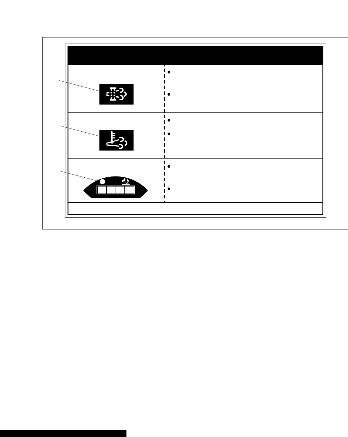
Pre-2013 DEF supply lines are electrically-heated
and are purged when the engine is shut down; com-
plete purging of the DEF lines requires approximately
five minutes after the engine is shut down.
DEF supply lines with engine model year 2013 and
newer are designed to survive freezing conditions
while containing DEF, so purging is not required.
DEF Tank
Engines that are compliant with EPA10 and newer
regulations are equipped with a DEF tank located on
the driver’s side of the vehicle behind the battery box
or forward of the fuel tank. See Fig. 12.7 and
Fig. 12.8. The DEF tank has a 19 mm filler neck inlet
that prevents the hose from a diesel outlet from
being inserted, and has a blue cap for easy
identification.
Fuel/DEF Gauge
The diesel fuel and DEF levels are measured in a
dual-purpose gauge. See Fig. 12.9.
Fuel level is indicated at the top of the gauge. Below
the fuel level, a low fuel warning lamp illuminates
amber when the fuel level drops below 1/8th of the
capacity.
The lower portion of the gauge has a DEF warning
lamp that illuminates amber when the DEF tank is
near empty, and a lightbar that indicates the level of
DEF in the tank. The DEF light bar illuminates as fol-
lows.
•Four bars illuminated green—Between 75%
and 100% full
•Three bars illuminated green—Between 50%
and 75% full
•Two bars illuminated green—Between 25%
and 50% full
DPF Regen Needed
Hot Exhaust
DEF Refill Needed
Diesel Particulate Filter (DPF)
regeneration is needed.
If flashing, regenerate as soon as
possible. Engine derate possible.
Hot exhaust can cause fire.
Keep flammables and people away
from exhaust.
Diesel Exhaust Fluid (DEF) level is
low. Engine derate likely.
Refill tank with certified DEF.
See operator’s manual for complete instructions. 24−01656−000
IMPORTANT
DEF
11/30/2010 f080161
1
2
3
Fig. 12.2, Warning Lamp Decal, Sun Visor
Emissions and Fuel Efficient Components
12.4
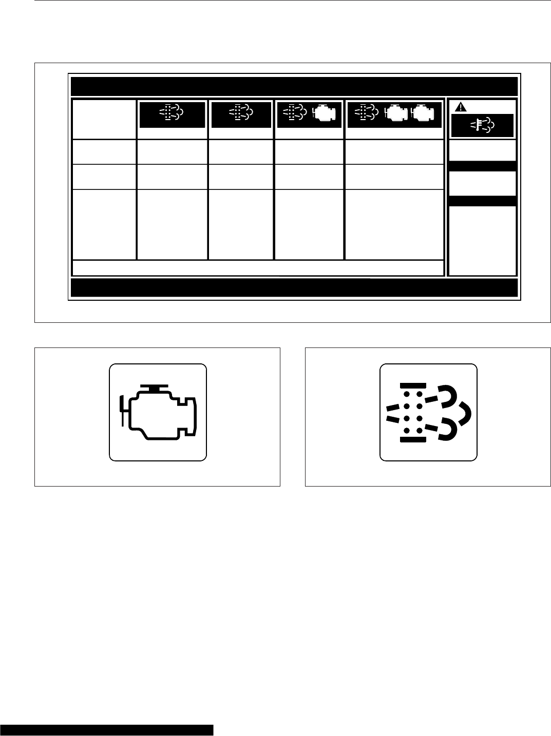
•One bar illuminated green—Between approxi-
mately 10% and 25% full
•One bar illuminated amber—DEF very low, re-
fill DEF
•One bar flashing red—DEF empty, refill DEF
DEF Warnings and Engine Limits
IMPORTANT: Ignoring the DEF warning lights
results in limited engine power, with the applica-
tion of a 5 mph (8 km/h) speed limit.
DEF Level Low—Initial Warning
When the DEF level is low, the following lamps notify
the driver. See Fig. 12.10. Refill the DEF tank in
order to cancel the warning sequence.
•One bar of the DEF level indicator illuminates
amber—DEF very low, refill DEF.
•The DEF warning lamp illuminates solid amber.
f080147
EXHAUST AFTERTREATMENT SYSTEM INFORMATION
Switch.
Level 1 Level 3Level 2 Level 4
Filter Regeneration
Recommended
Filter is reaching
Bring vehicle to
highway speeds to
Filter Regeneration
Necessary
Filter is now
reaching maximum
capacity
.
To avoid engine
derate bring vehicle
Parked Regeneration
Required − Engine
Derate
Filter has reached
maximum capacity
.
Vehicle must be
parked and a Parked
Parked Regeneration Required −
Engine Shut Down
Filter has exceeded
maximum capacity
Vehicle must be parked and a
Parked Regeneration or Service
(Solid)
(Flashing) (Flashing)
CHECK CHECK
(Flashing)
INDICATOR
LAMP(S)
Indicator Lamp
Message(s)
Diesel Particulate
Filter Condition
Required Action
capacity
. .
STOP
See Engine Operator’s Manual for complete Regeneration Instructions.
allow for an Automatic
Regeneration or
perform a Parked
Regeneration.
to highway speeds
to allow for an
Automatic
Regeneration or
perform a Parked
Regeneration as
soon as possible.
Regeneration must
be performed −
engine will begin
derate.
Regeneration must be performed.
Check engine operator’s manual
for details −engine will shut down.
For a driver performed Parked Regeneration, vehicle must be equipped with a dash mounted Regeneration Switch.
06/29/2009
24−01583−000B
W
ARNING
HEST (High Exhaust
System Temperature)
Exhaust Components
and exhaust gas are
at high temperature.
When stationary, keep
away from people and
flammable materials
or vapors.
A regeneration is in
progress.
Flashing
Solid
Fig. 12.3, ATS Warning Lamps
09/25/2006 f610814a
Fig. 12.4, Malfunction Indicator Lamp (MIL)
09/25/2006 f610815a
Fig. 12.5, DPF Status Lamp
Emissions and Fuel Efficient Components
12.5
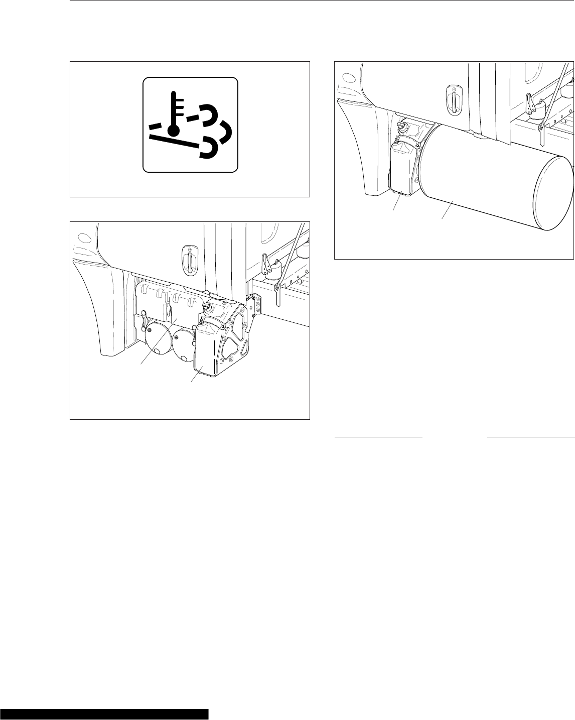
DEF Empty
When the DEF level reads empty, the following
lamps notify the driver. See Fig. 12.11.
•One bar of the DEF level indicator flashes
red—DEF empty, refill DEF.
•The DEF warning lamp flashes amber.
•The MIL lamp illuminates.
Pre-2013 Detroit engines: Power is limited, with a 55
mph (90 km/h) speed limit.
Cummins and 2013 Detroit engines: Power is limited
with progressively harsher engine power limits
applied.
DEF Tank Empty and Ignored
If the empty warning is ignored and the DEF tank is
not refilled, the red STOP engine lamp illuminates in
addition to the MIL lamp and CHECK engine lamp
(on vehicles with a Cummins ISB or ISC/L engine.)
See Fig. 12.12.
If the DEF is not refilled, a 5 mph (8 km/h) speed
limit is applied after the next engine shutdown, while
parked and idling, or if a fuel refill is detected.
DEF Contamination or SCR Tampering
NOTICE
Once contaminated DEF or tampering has been
detected, the vehicle must be taken to an autho-
rized service facility to check the SCR system for
damage and to deactivate the warning lights and
engine limits.
If contaminated DEF or tampering with the ATS is
detected, the DEF warning light flashes and the MIL
lamp illuminates to warn the driver. The CHECK en-
gine lamp also illuminates on vehicles with a Cum-
mins ISB or ISC/L engine. See Fig. 12.12.
•Detroit engines: Engine power is limited with
progressively harsher limits applied. If the fault
09/25/2006 f610816a
Fig. 12.6, HEST Lamp
07/24/2009 f470542
1
2
1. Batteries 2. DEF Tank
Fig. 12.7, DEF Tank Located Behind the Battery Box
07/24/2009 f470541
1
2
1. DEF Tank 2. Fuel Tank
Fig. 12.8, DEF Tank Located Forward of the Fuel Tank
Emissions and Fuel Efficient Components
12.6
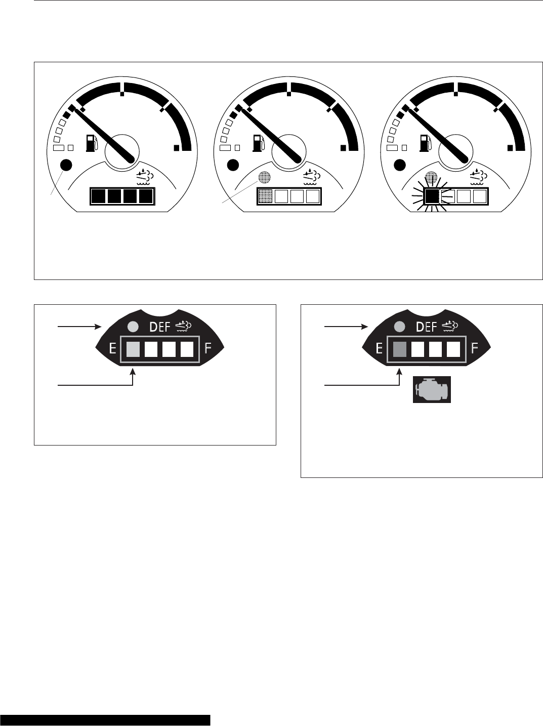
is not corrected, the STOP engine light illumi-
nates and a 5 mph (8 km/h) speed limit is ap-
plied after the next engine shutdown, while
parked and idling, or if a fuel refill is detected.
•Cummins engines: Engine power is limited with
progressively harsher limits applied. If the fault
is not corrected, the STOP engine light illumi-
nates and a 5 mph (8 km/h) speed limit is ap-
plied after the next engine shutdown, or while
parked and idling.
11/08/2010 f611037
B
1/2
ULTRA LOW SULFUR
DIESEL FUEL ONLY
EF
DEF
FE
1/2
ULTRA LOW SULFUR
DIESEL FUEL ONLY
EF
DEF
FE
1/2
ULTRA LOW SULFUR
DIESEL FUEL ONLY
EF
DEF
FE
A C
12
A. Green bars—DEF level indicators
B. One bar illuminated amber—DEF very low, refill DEF
C. One bar flashing red—DEF empty, refill DEF
1. Low Fuel Warning Lamp 2. DEF Warning Lamp
Fig. 12.9, Fuel/DEF Gauge
A
B
07/09/2009 f470537
A. DEF Warning Lamp (illuminated)
B. DEF Lightbar (one bar amber)
Fig. 12.10, DEF Level Low Initial Warning
A
B
11/08/2010 f470539a
NOTE: MIL illuminates. CHECK engine lamp illuminates
if Cummins ISB or ISC/L engine. Engine power is lim-
ited.
A. DEF Warning Lamp (flashing)
B. DEF Lightbar (one bar flashing red)
Fig. 12.11, DEF Empty Warning
Emissions and Fuel Efficient Components
12.7
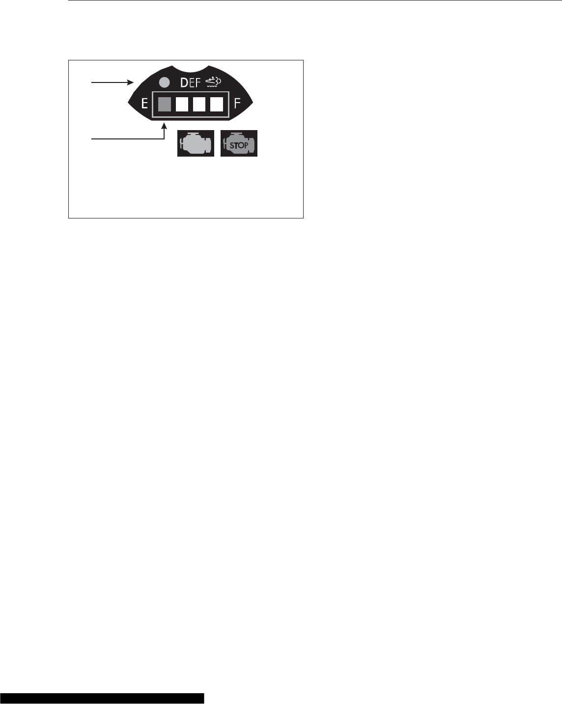
A
B
11/08/2010 f470540a
NOTE: STOP engine light and MIL illuminate, engine
power is limited, speed limit of 5 mph (8 km/h)
A. DEF Warning Lamp (flashing)
B. DEF Lightbar (one bar flashing red)
Fig. 12.12, DEF Empty and Ignored Warning
Emissions and Fuel Efficient Components
12.8

13
Brake Systems
Air Brake System ................................................................ 13.1
Meritor WABCO® Antilock Braking System ........................................... 13.3
Engine Brake ................................................................... 13.5
Air Brake System
Brake System General Information
A dual air brake system consists of two independent
air systems that use a single set of brake controls.
Each system has its own reservoirs, plumbing, and
brake chambers. The primary system operates the
service brakes on the rear axle; the secondary sys-
tem operates the service brakes on the front axle.
Service brake signals from both systems are sent to
the trailer.
WARNING
Do not operate the vehicle with the front brakes
backed off or disconnected. Backing off or dis-
connecting the front brakes will not improve ve-
hicle handling and may lead to loss of vehicle
control, resulting in property damage or personal
injury.
Brake System Components
The warning light and buzzer come on if air pressure
drops below approximately 70 psi (483 kPa) in either
system. If this happens, check the air pressure
gauges to determine which system has low air pres-
sure. Although the vehicle’s speed can be reduced
using the foot brake control pedal, either the front or
rear service brakes will not be operating at full ca-
pacity, causing a longer stopping distance. Bring the
vehicle to a safe stop and have the air system re-
paired before continuing.
IMPORTANT: In the event of a total loss of ser-
vice brakes with full system air pressure, use
the parking brake control valve (yellow knob) to
bring the vehicle to a complete stop in the saf-
est location possible.
Before a vehicle with insufficient system air pressure
can be moved, the spring parking brakes must be
released by applying an external air source at the
gladhands, or by manually caging the parking brake
springs.
WARNING
Do not release the spring parking brakes and
then drive the vehicle. There would be no means
of stopping the vehicle, which could result in se-
rious personal injury or vehicle damage. Before
releasing the spring parking brakes, make the
connection to a towing vehicle or chock the tires.
After correcting the brake system problem, uncage
the spring parking brakes before resuming normal
vehicle operation.
Primary Air Brake System
Loss of air pressure in the primary air system causes
the rear service brakes to become inoperative. The
secondary air system will continue to operate the
front brakes and the trailer brakes (if equipped).
Secondary Air System
Loss of air pressure in the secondary air system
causes the front axle brakes to become inoperative.
The primary air system will continue to operate the
rear service brakes and the trailer brakes (if
equipped).
Brake System Operation
Before driving your vehicle, allow time for the air
compressor to build up a minimum of 100 psi (689
kPa) pressure in both the primary and secondary
systems. Monitor the air pressure system by observ-
ing the air pressure gauges and the low-air-pressure
warning light and buzzer. The warning light and
buzzer shut off when air pressure in both systems
reaches approximately 70 psi (483 kPa).
IMPORTANT: Before driving the vehicle, secure all
loose items in the cab so that they will not fly forward
during a full brake application. Make sure all passen-
gers are wearing seat belts.
During normal brake stops, depress the foot brake
control pedal until braking action slows down the ve-
hicle. Increase or decrease the pressure on the
pedal so that the vehicle comes to a smooth, safe
stop. Apply the spring parking brakes if the vehicle is
to be parked.
IMPORTANT: An air brake proportioning system
may be used in tractor air brake systems when
the vehicle is not equipped with antilock braking
system (ABS). When operating in bobtail mode,
the rear brake chambers (on which the axle
load has been greatly reduced) receive reduced
(proportional) air pressure, while the front axle
brake chambers receive full (normal) air pres-
sure. This results in a different brake pedal
"feel," as the pedal seems to require more travel
Brake Systems
13.1
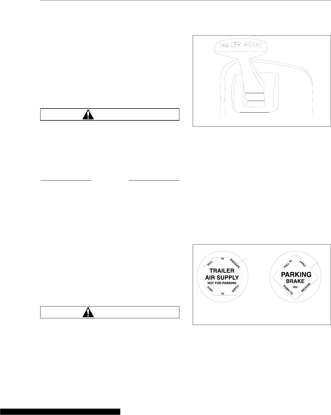
and/or effort to slow or stop the vehicle. How-
ever, the air brake proportioning system actually
improves vehicle control when the tractor is in
bobtail mode. When the tractor is towing a
trailer, the rear brake chambers will receive full
(normal) application air pressure.
When parking a vehicle attached to a trailer that
does not have spring parking brakes, apply the trac-
tor parking brakes. Chock the trailer tires before dis-
connecting the vehicle from the trailer.
WARNING
If a trailer or combination vehicle is not equipped
with spring parking brakes, do not park it by pull-
ing out only the trailer air supply valve knob.
This would apply only the trailer service brakes.
If air were to bleed from the trailer brake system,
the trailer brakes would release, possibly causing
an unattended runaway vehicle.
NOTICE
Never apply the service and spring parking
brakes simultaneously. To do so transmits exces-
sive input force to the brake components, which
could damage or cause eventual failure of brake
actuating components.
Brake Controls
The trailer brake lever (hand control valve) is used
for applying the trailer brakes without applying the
truck or tractor service brakes. It is usually mounted
on the right-hand control panel. See Fig. 13.1. The
valve can be partially or fully applied, but in any par-
tially on position it will be overridden by a full applica-
tion of the service brake pedal. Moving the lever
down applies the trailer brakes, while moving it up
releases the trailer brakes. The lever will automati-
cally return to the up position when it is released.
WARNING
Do not use the trailer service brakes for parking;
they are not designed for this purpose. If air
bleeds out of the trailer air tank during parking,
the vehicle could roll, causing serious personal
injury or property damage.
The red octagonal-shaped knob in the control panel
actuates the trailer air supply valve. See Fig. 13.2.
After the vehicle’s air hoses are connected to a
trailer and the pressure in both air systems is at least
65 psi (448 kPa), the trailer air supply valve must be
pushed in. It should stay in to charge the trailer air
supply system and to release the trailer spring park-
ing brakes.
Pull the trailer air supply valve out before disconnect-
ing a trailer or when operating a vehicle without a
trailer. If pressure in both air systems drops to 35 to
45 psi (242 to 310 kPa), the trailer air supply valve
automatically pops out, exhausting the trailer air sup-
ply, and applying the trailer service or spring parking
brakes.
The yellow diamond-shaped knob in the control
panel actuates the parking brake valve. See
Fig. 13.2. Pulling out the parking brake valve applies
both the tractor and trailer spring parking brakes and
10/17/2001 f610591
Fig. 13.1, Trailer Brake Lever
f610291
1 2
03/10/99
1. Trailer Air-Supply-Valve Knob
2. Parking-Brake-Valve Knob
Fig. 13.2, Brake Valve Knobs
Brake Systems
13.2

automatically causes the trailer air supply valve to
pop out.
NOTICE
Do not use the spring parking brakes if the ser-
vice brakes are hot, such as after descending a
steep grade. To do so could damage the brakes.
Allow hot brakes to cool before using the spring
parking brakes.
Do not use the spring parking brakes during
freezing temperatures if the service brakes are
wet. To do so could cause them to freeze. If the
brakes are wet, drive the vehicle in low gear and
lightly apply the brakes to heat and dry them.
If the trailer is not equipped with spring parking
brakes, pulling out the parking brake valve applies
the tractor spring parking brakes and the trailer ser-
vice brakes. When the tractor and trailer parking
brakes (or trailer service brakes) are both applied,
the trailer brakes are released by pushing in the
trailer air supply valve, leaving the tractor parking
brakes applied. Air pressure in the primary or sec-
ondary reservoir must be at least 65 psi (447 kPa)
before the tractor spring parking brakes, or the trailer
service or spring parking brakes, can be released.
Automatic Slack Adjusters
Automatic slack adjusters should never be manually
adjusted except during routine maintenance of the
foundation brakes (e.g., replacing shoes), during
slack adjuster installation, or in an emergency situa-
tion.
When the brake pushrod stroke exceeds the legal
brake adjustment limit on a vehicle, there is likely a
mechanical problem with the foundation brake com-
ponents or the adjuster is improperly installed.
Visit a repair facility as soon as possible when
brakes equipped with automatic slack adjusters are
determined to be out of adjustment.
WARNING
Manually adjusting an automatic slack adjuster to
bring the pushrod stroke within legal limits is
likely masking a mechanical problem. Adjustment
is not a repair. Before adjusting an automatic
slack adjuster, troubleshoot the foundation brake
system and inspect it for worn or damaged com-
ponents. Improperly maintaining the vehicle brak-
ing system may lead to brake failure, resulting in
property damage, personal injury, or death.
Meritor WABCO® Antilock
Braking System
The Meritor WABCO Antilock Braking System (ABS)
is an electronic wheel speed monitoring and control
system that works with the standard air brake sys-
tem. ABS passively monitors vehicle wheel speed at
all times, and controls wheel speed during emer-
gency stops.
IMPORTANT: For proper ABS system operation,
do not change tire sizes. The sizes of the tires
installed during production are programmed into
the electronic control unit. Installing different-
sized tires could result in a reduced braking
force, leading to longer stopping distances.
ABS includes signal-generating tone wheels and sen-
sors located in the wheel hubs of each sensed
wheel. The sensors transmit vehicle wheel speed
information to an electronic control unit (located be-
hind the center dash). The control unit’s main circuit
interprets the speed sensor signals and calculates
wheel speed, wheel retardation, and a vehicle refer-
ence speed. If the calculations indicate wheel lockup,
the main circuit signals the appropriate modulator
valve to reduce braking pressure. During emergency
braking, the modulator valve alternately reduces, in-
creases, or maintains air pressure supply in the
brake chamber to prevent front and rear wheel
lockup.
The electronic control unit (ECU) also has a safety
circuit that constantly monitors the wheel sensors,
traction control valve (if equipped), modulator valves,
and the electrical circuitry.
The Meritor WABCO ABS combines one front-axle
control channel with one rear-axle control channel to
form one control circuit. For example, the sensor and
modulator valve on the left-front axle form a control
circuit with the sensor and modulator valve on the
right-rear axle. If, during vehicle operation, the safety
circuit senses a failure in any part of the ABS, the
tractor warning lamp (TRACTOR ABS) illuminates
and the control circuit where the failure occurred is
switched to normal braking action. The remaining
control circuit will retain the ABS effect. Even if the
ABS is completely inoperative, normal braking ability
Brake Systems
13.3

is maintained. An exception would be if a modulator
valve (or combination modulator valve) is damaged
and inoperative. As these components are an integral
part of the air brake system, normal braking may be
impaired or inoperative.
During emergency or reduced-traction stops, fully
depress the brake pedal until the vehicle comes to a
safe stop. Do not pump the brake pedal. With the
brake pedal fully depressed, the ABS will control all
wheels to provide steering control and a reduced
braking distance.
Although the ABS improves vehicle control during
emergency braking situations, the driver still has the
responsibility to change driving styles depending on
existing traffic and road conditions. For example, the
ABS cannot prevent an accident if the driver is
speeding or following too closely.
Trailer ABS Compatibility
The Meritor WABCO ABS is designed to communi-
cate with a trailer ABS, if they are compatible. Com-
patibility will result in the illumination of the TRAILER
ABS lamp during vehicle start-up and fault detection.
The TRAILER ABS lamp will not illuminate unless a
compatible trailer is connected to the tractor. The
dash-mounted lamp will operate as follows when a
compatible trailer is properly connected to the tractor:
•When the ignition key is turned to the ON posi-
tion, the TRAILER ABS lamp will illuminate mo-
mentarily, then turn off.
•If the lamp illuminates momentarily during ve-
hicle operation, then shuts off, a fault was de-
tected and corrected.
•If the lamp illuminates and stays on during ve-
hicle operation, there is a fault with the trailer
ABS. Repair the trailer ABS system immedi-
ately to ensure full antilock braking capability.
IMPORTANT: If a compatible trailer is con-
nected, and the lamp is not illuminating momen-
tarily when the ignition key is turned to the ON
position, it is possible that the lamp is burnt out.
Automatic Traction Control
Vehicles with electronic engines and ABS may have
Automatic Traction Control (ATC). On these vehicles,
the ATC system automatically limits wheel spin dur-
ing reduced-traction situations. In normal braking ap-
plications, the standard air brake system is in effect.
An additional solenoid valve is installed. During
reduced-traction situations, the ATC solenoid valve
controls air pressure to the modulator valves and
they in turn increase, hold, or reduce pressure to the
appropriate brake chambers to provide better traction
whenever wheel spin occurs.
When the ATC system is in the NORMAL mode, it
will apply gentle braking to the spinning wheel, to
feed power to the wheel(s) with better traction. If
both wheels are spinning, the system will signal the
engine to reduce power.
ATC includes a deep snow and mud option to in-
crease available traction on extra soft surfaces like
snow, mud, or gravel. A rocker switch labeled ATC
will be located on the dash. Pressing the switch will
temporarily allow more drive wheel spin. The activa-
tion of the deep snow and mud option is indicated by
a flashing WHEEL SPIN lamp. Pressing the switch
again will cycle the system back to normal operation.
NOTICE
The deep snow and mud option is intended to be
used under specific slippery conditions that re-
quire momentary increased wheel spin. Using
this option for an extended period of time may
damage the vehicle brake system.
After the ignition switch is turned on, the TRACTOR
ABS lamp and the WHEEL SPIN indicator lamp
come on for about three seconds. After three sec-
onds, the warning lights go out if all of the tractor’s
ABS components are working.
IMPORTANT: If any of the ABS warning lights
do not work as described above, or come on
while driving, repair the ABS immediately to en-
sure full antilock braking capability.
ECAS Automatic Load Transfer
(ECAS only)
On those vehicles equipped with Electronically Con-
trolled Air Suspension (ECAS), ECAS works in con-
junction with ABS. When wheel slippage is detected
by the ABS, the ECAS system transfers weight from
the tag axle to the drive axle by changing air pres-
sures in the suspension air bellows, increasing drive
wheel traction.
Brake Systems
13.4
Engine Brake
Each engine manufacturer uses a specific engine
brake for their engine. Regardless of the manufac-
turer, the engine brake is operated with the principles
outlined in here. Refer to the engine manufacturer’s
operation manual for details of their particular engine
brake product.
WARNING
To avoid injury from loss of vehicle control, do
not activate the engine brake system under the
following conditions:
•on wet or slippery pavement, unless the
vehicle is equipped with antilock braking
system (ABS) and you have had prior expe-
rience driving under these conditions;
•when driving without a trailer or pulling an
empty trailer;
•if the tractor drive wheels begin to lock, or
there is fishtail motion after the engine
brake is activated.
NOTE: When the engine brake is enabled, the
engine brake lamp illuminates in the ICU. See
Fig. 13.3, Item 1.
Whenever vehicle braking is required on good road
conditions, the engine brake may be used in con-
junction with the service brakes. There is no time
limit for operation of the engine brake. However, an
engine brake does not provide the precise control of,
and is not a substitute for, service brakes.
WARNING
Usage of the engine brake as the primary braking
system can cause unpredictable stopping dis-
tances, that could result in personal injury or
property damage. Service brakes are the primary
vehicle braking system.
Since the engine brake is most effective at rated en-
gine speed, gear selection is very important. Gearing
down the vehicle within the limits of the rated engine
speed makes the engine brake more effective. Rec-
ommended engine braking speed is above 1800 rpm
and below the rated speed.
WARNING
The engine brake must be disengaged when
shifting gears using the clutch pedal. If the en-
gine brake is engaged when the transmission is
in neutral, the braking power of the engine brake
can stall the engine, which could result in loss of
vehicle control, possibly causing personal injury
and property damage.
"Control speed" is the speed at which the engine
brake performs 100 percent of the required downhill
braking, resulting in a constant speed of descent.
The control speed varies, depending on vehicle
weight and the downhill grade.
For faster descent, select a higher gear than that
used for control speed. Service brakes must then be
used intermittently to prevent engine overspeed and
to maintain desired vehicle speed.
For slower descent, select a lower gear, being care-
ful not to overspeed the engine. Occasional deactiva-
tion of the engine brake may be necessary to main-
tain the designated road speed under these
conditions.
If the engine is equipped with both cruise control and
an engine brake, the engine brake can operate auto-
matically while cruise control is activated. The maxi-
mum amount of braking is selected with the engine
brake control. When the vehicle returns to the set
cruise speed, the engine brake will turn off.
The engine brake will only operate when the accel-
erator and clutch pedals are fully released.
Vehicles equipped with ABS have the ability to turn
the engine brake off if wheel slip is detected. The
engine brake will automatically turn back on once
wheel slip is no longer detected.
Engine Brake Operation
NOTICE
Do not allow the engine to exceed its governed
speed, or serious engine damage could result.
NOTE: Depending on the brake type, the engine
brake may be disabled when engine tempera-
ture falls below a set level.
Brake Systems
13.5
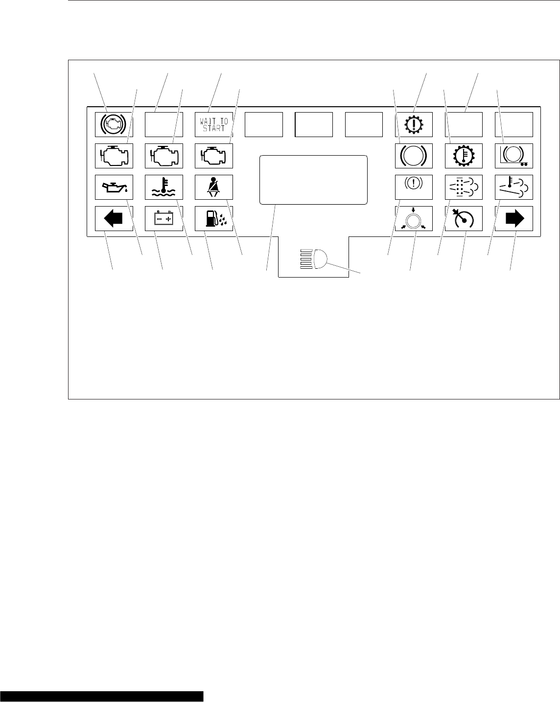
The engine brake control depends on vehicle con-
figuration. On some vehicles, there is an engine
brake (ENG BRK) switch located in the right-hand
pod on the steering wheel that is used to turn the
engine brake on and off, and an engine brake level
switch on the dash used to set the intensity—high,
medium, or low. See Fig. 13.4 and Fig. 13.5.
On vehicles equipped with a column-mounted Detroit
multifunction control, the engine brake is controlled
by the lever position, as shown in Fig. 13.6. At the
top position, the engine brake is off, and at the three
lower positions, the engine brake is on and the inten-
sity (low, medium, high) increases with each step
down.
NOTE: On vehicles equipped with a Detroit mul-
tifunction control, setting the engine brake with
the cruise control set activates Deceleration
Mode. Setting the cruise control while the en-
gine brake is on activates Descent Control
Mode. For information on these modes, see
"Cruise Control" in Chapter 5.
On vehicles equipped with an engine brake switch in
the right-hand pod on the steering wheel, operate the
engine brake after the engine is warmed up and the
vehicle is in motion, as follows:
1. Remove feet from both the clutch and accelera-
tor pedals.
2. Press the upper half of the on/off switch (see
Fig. 13.4) to turn the engine brake on. The en-
gine brake will engage at the rate last set on the
engine brake intensity switch and the engine
brake lamp will illuminate.
ABS ABS
CHECK STOP
OPT 2 OPT 4 OPT 5 OPT 6 OPT 9
05/07/2012 f611094
1
6 7 8 9 10 11
12 13 14 15 16 17
18 19 21 22 24 2520 23
234 5
IDLE
MGMT
BRAKE
1. Engine Brake
2. Optional
3. Wait To Start
4. Check Transmission
5. Optimized Idle
6. CHECK Engine
7. STOP Engine
8. Malfunction Indicator Lamp (MIL)
9. Vehicle ABS
10. Transmission Overheat
11. Trailer ABS
12. Low Engine Oil Pressure
13. High Coolant Temperature
14. Unfastened Seat Belt
15. Park Brake On
16. Diesel Particulate Filter (DPF)
Status
17. High Exhaust Temperature
(HEST)
18. Left-Turn Signal
19. Low Battery Voltage
20. Water In Fuel
21. Driver Message Center
22. High Beams On
23. Brake Air
24. Cruise Control On
25. Right-Turn Signal
Fig. 13.3, ICU3 Message Center (typical)
Brake Systems
13.6
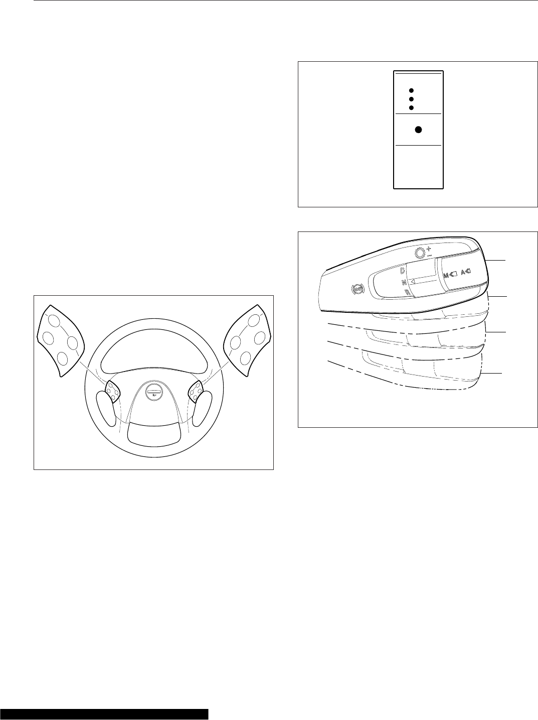
3. Press the upper or lower half of the intensity
switch (see Fig. 13.5) to select the desired brak-
ing intensity.
Use the intensity switch set at the LOW position
when driving on flat, open stretches of road. If
the service brakes are still required to slow down
on a grade, switch to a higher setting on the
dash switch to maintain constant speed of de-
scent. Grade descent speed should be such that
the service brakes are used infrequently and re-
main cool, thus retaining their effectiveness.
4. For maximum retarding, maintain the top gov-
erned speed of the engine through the appropri-
ate selection of gears. When shifting gears, the
engine brake will disengage when the clutch
pedal is depressed, then engage when the clutch
pedal is released.
5. To cancel the engine brake application, press the
lower half of the on/off switch.
06/15/2007
ON/
OFF
ACC/
RES
CNCL
DEC/
SET
MRKR
INT
ENG
BRK
−
+
f462049a
Fig. 13.4, Steering Wheel Switches
ENG
BRK
f61090505/02/2007
HI
LO
Fig. 13.5, Engine Brake Level Switch
0
1
2
3
02/19/2013 f270164a
0. Off
1. Low
2. Medium
3. High
Fig. 13.6, Engine Brake Positions, Detroit Multifunction
Control
Brake Systems
13.7

14
Manual Transmissions and
Hydraulic Clutch
Eaton Fuller 13-Speed and 18-Speed Splitter and Range-Shift Transmissions ............... 14.1
Eaton Fuller 10-Speed Range-Shift Transmissions ..................................... 14.4
Clutch ......................................................................... 14.5
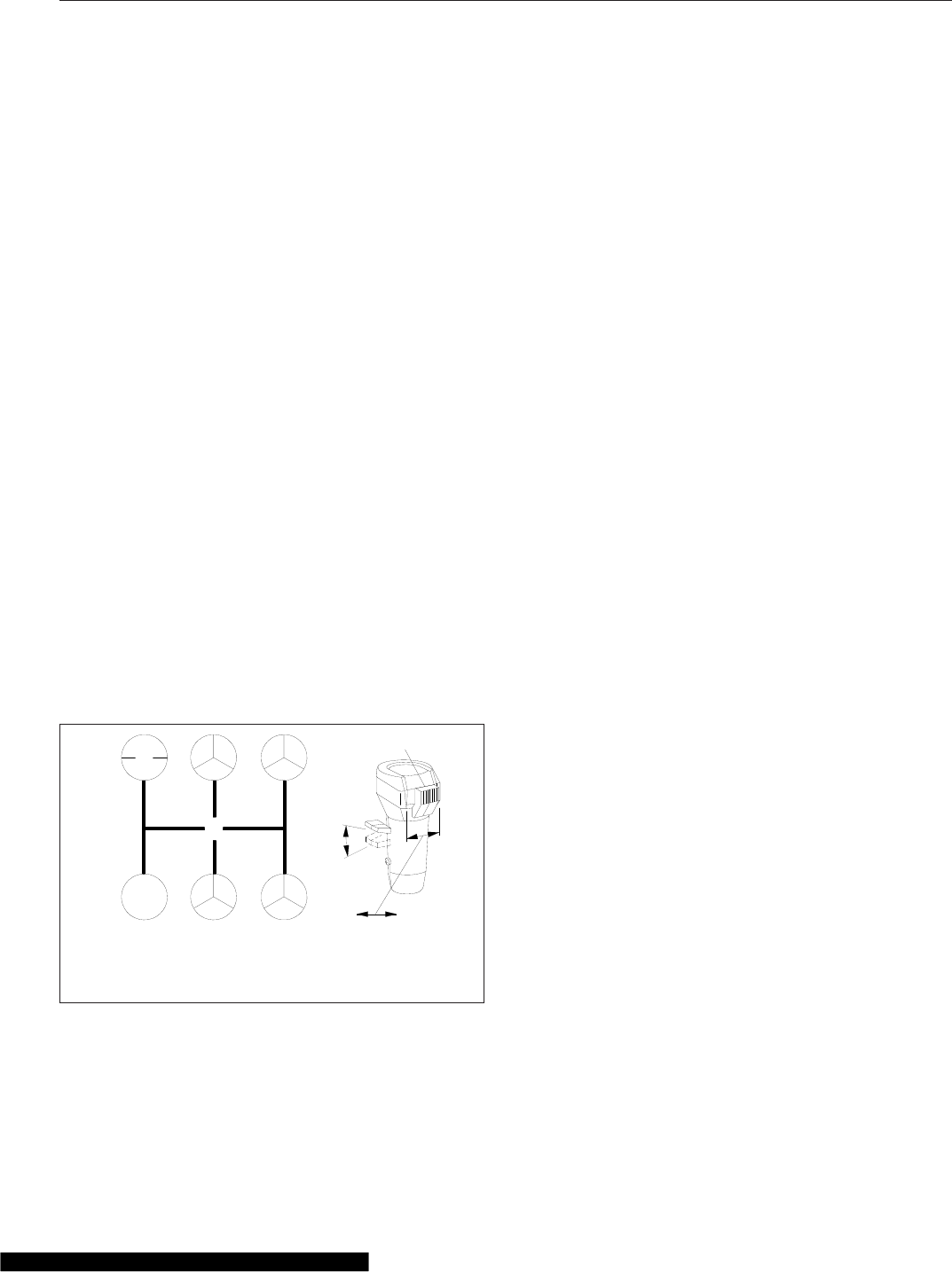
Eaton Fuller 13-Speed and 18-
Speed Splitter and Range-Shift
Transmissions
Refer to the Eaton website for additional information,
www.roadranger.com.
General Information, Eaton Fuller
Splitter and Range-Shift
Combination splitter and range-shift transmissions
allow the choice of two splitter ratios in each lever
position as well as the additional ratio provided in
each lever position after shifting to the other range.
IMPORTANT: Not all lever positions are used in
each range and the shift patterns vary between
transmissions. Be sure to read the shift pattern
decal on the dash for the operating instructions
for the specific transmission installed in your ve-
hicle.
13-Speed RTLO Models
Eaton Fuller 13-speed transmissions have thirteen
forward speeds and two reverse speeds. Each trans-
mission consists of a 5-speed front section, and a
3-speed auxiliary section. The auxiliary section con-
tains low- and high-range ratios, plus an overdrive
splitter gear. See Fig. 14.1 for the shift pattern.
All of the 13 speeds are controlled with one shift
lever. A range preselection lever and a splitter control
button are built into the shift knob. The range prese-
lection lever controls range selection and the splitter
control button (located on the side of the shift knob)
controls gear splits.
Low gear in the front section is used only as a start-
ing ratio. The remaining four forward positions are
used once in the low range and once in the high
range. However, each of the four high range gear
positions can be split with the underdrive ratio (RT
models), or overdrive ratio (RTO models) of the split-
ter gear. Ratios cannot be split while the transmis-
sion is in low range.
18-Speed RTLO Splitter and Range-Shift
Models
Eaton Fuller 18-speed transmissions have 18 forward
speeds and four reverse speeds. These transmis-
sions consisting of a 5-speed front section and a
3-speed auxiliary section. The auxiliary section con-
tains low and high range ratios, plus an overdrive
splitter gear.
One ratio in the front section (low) is used as a start-
ing ratio; it is never used when the transmission is in
high range. Low gear can be split to provide both a
direct and an overdrive ratio.
The other four ratios in the front section are used
once in low range and once again in high range;
however, each of the five ratios (low–1–2–3–4) in low
range and each of the four ratios (5–6–7–8) in high
range can be split with the overdrive splitter gear.
All of the 18 speeds are controlled with one shift
lever. A range preselection lever and a splitter control
button are built into the shift knob. The range prese-
lection lever controls range selection and the splitter
control button (located on the side of the shift knob)
controls gear splits.
Operation, Eaton Fuller Splitter and
Range-Shift
IMPORTANT: The shifter knob has an interlock
feature that prevents the splitter control button
from being moved forward when the range pre-
selection lever is down (in low range); when in
high range and the splitter control button is in
the forward position, the range preselection
lever cannot be moved down.
R1 3
24
LOW
Dir OD
55
Dir OD
Dir OD Dir OD
77
66 8 8
Hi
Lo
A
B
CD
1
03/13/96 f260044a
N
A. High Range
B. Low Range
C. Overdrive (forward)
D. Direct Drive (rearward)
1. Splitter Control Button
Fig. 14.1, Eaton Fuller 13-Speed Transmission Shift
Pattern
Manual Transmissions and Hydraulic Clutch
14.1
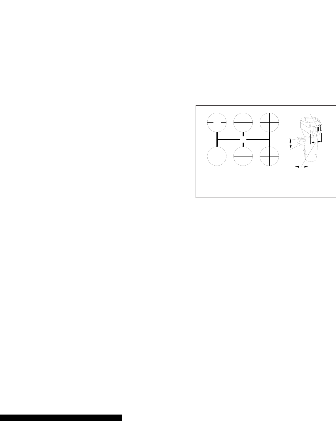
1. When operating off-road, or under adverse condi-
tions, always use low gear when starting to move
the vehicle forward.
When operating on-highway, with no load, or
under ideal conditions, use 1st gear when start-
ing to move the vehicle forward.
For all conditions, use the highest gear that is
still low enough to start the vehicle moving with
the engine at or near idle speed, and without
slipping the clutch excessively.
2. Use the clutch brake to stop gear rotation when
shifting into low (or 1st) or reverse when the ve-
hicle is stationary. The clutch brake is actuated
by depressing the clutch pedal all the way to the
floor.
For normal upshifts and downshifts, only a partial
disengagement of the clutch is necessary to
break engine torque.
3. Use double-clutching between all upshifts and
downshifts that require movement of the shift
lever. Splitting of the high range gears does not
require movement of the shift lever.
4. Never move the shift lever into low gear while in
high range.
5. Never move the splitter control button while in
neutral.
6. Do not preselect with the splitter control button;
after moving the control button, complete the
shift immediately.
7. Except when downshifting from 5th direct to 4th
gear, never push the range preselection lever
down into low range while operating in high
range—the splitter will become inoperative.
8. Do not shift from high range to low range at high
vehicle speeds.
9. Do not make range shifts with the vehicle moving
in reverse gear.
10. Never attempt to move the range preselection
lever with the gear shift lever in neutral while the
vehicle is moving. Preselection with the range
preselection lever must be made prior to moving
the shift lever out of gear into neutral.
11. After your shifting ability improves, you may want
to skip some of the ratios. This may be done
only when operating conditions permit, depend-
ing on the load, grade, and road speed.
Upshifting
1. Position the gear shift lever in neutral. Start the
engine, and bring the air system pressure up to
100 to 120 psi (689 to 827 kPa).
2. Position the range preselection lever down, into
low range. See Fig. 14.2.
3. Make sure the splitter control button is in the di-
rect (rearward) position. See Fig. 14.2.
4. For 13-speed transmissions:
Press the clutch to the floor, shift into low or 1st
gear; then engage the clutch, with the engine at
or near idle speed, to start the vehicle moving.
Accelerate to 80 percent of engine governed
speed.
For 18-speed transmissions:
Press the clutch to the floor, shift into low; then
engage the clutch, with the engine at or near idle
speed, to start the vehicle moving.
To shift from low direct to low overdrive, move
the splitter control button into the overdrive (for-
ward) position, then immediately release the ac-
celerator. Press and release the clutch pedal.
After releasing the clutch, accelerate again.
5. For 13-speed transmissions:
Shift upward from low to 1st gear, 2nd, etc. until
4th gear, double-clutching between shifts, and
N
R1
Dir
5
Dir 5
OD
1
OD 3
Dir
7
Dir 7
OD
3
OD
2
Dir
6
Dir 6
OD
2
OD 4
Dir
8
Dir 8
OD
4
OD
LOW
Dir
LOW
OD
A
B
CD
1
03/13/96 f260157a
A. High Range
B. Low Range
C. Overdrive (forward)
D. Direct Drive (rearward)
1. Splitter Control Button
Fig. 14.2, Eaton Fuller 18-Speed Transmission Shift
Pattern
Manual Transmissions and Hydraulic Clutch
14.2

accelerating to 80 percent of engine governed
speed. See Fig. 14.1.
For 18-speed transmissions:
Shift upward from low overdrive to 1st direct by
first moving the splitter control button into the
direct (rearward) position (Fig. 14.2). Move the
shift lever, double-clutching, to the 1st gear posi-
tion.
Continue upshifting through the shift pattern.
Double-clutch during lever shifts (1st to 2nd to
3rd to 4th); single-clutch during split shifts (1st
direct to 1st overdrive, etc.).
6. When in 4th gear (13-speed transmissions) or
4th overdrive (18-speed transmissions) and
ready to shift up to 5th gear, use the range shift
lever as follows:
For 13-speed transmissions:
While in 4th gear, pull the range shift preselec-
tion lever up, into high range. The transmission
will automatically shift from low to high range as
the shift lever passes through neutral. Then, dis-
engage the clutch; double-clutch through neutral;
move the shift lever to 5th gear; engage the
clutch, and accelerate the engine.
For 18-speed transmissions:
While in 4th overdrive, pull the range shift prese-
lection lever up, into high range. The transmis-
sion will automatically shift from low to high
range as the shift lever passes through neutral.
Move the shift lever, double-clutching, to the 5th
gear position. Just before making final clutch en-
gagement, move the splitter control button to the
direct (rearward) position; then engage the clutch
and accelerate. Do not move the control button
while the shift lever is in neutral.
7. Shift up through the high range gears as follows:
For 13-speed transmissions:
To shift from 5th direct to 5th overdrive, move the
splitter control button (Fig. 14.1) into the over-
drive (forward) position, then immediately release
the accelerator. Press and release the clutch
pedal. After releasing the clutch, accelerate
again.
Continue upshifting through the shift pattern.
Double-clutch during lever shifts (6th to 7th to
8th); single-clutch during split shifts (6th direct to
6th overdrive, etc.).
For 18-speed transmissions:
To shift from 5th direct to 5th overdrive, move the
splitter control button (Fig. 14.2) into the over-
drive (forward) position, then immediately release
the accelerator. Press and release the clutch
pedal. After releasing the clutch, accelerate
again.
Continue upshifting through the shift pattern.
Double-clutch during lever shifts (6th to 7th to
8th); single-clutch during split shifts (6th direct to
6th overdrive, etc.).
Downshifting
1. Downshift from 8th overdrive to 8th direct without
moving the shift lever. Flip the splitter control but-
ton to the direct (rearward) position, then imme-
diately release the accelerator, and disengage
the clutch. Engage the clutch, and accelerate the
engine only after the transmission has shifted.
2. Start the downshift from 8th direct to 7th over-
drive by flipping the splitter control button to the
overdrive (forward) position; then, immediately
double-clutch through neutral, moving the shift
lever from 8th to 7th gear.
3. Shift downward through each of the high range
gears, alternating the procedures in steps 1 and
2, above, until reaching 5th direct.
4. While in 5th direct and ready for the downshift to
4th (13-speed transmissions) or 4th overdrive
(18-speed transmissions), push the range prese-
lection lever down. Then, double-clutch through
neutral and move the shift lever to the 4th gear
position. On 18-speed transmissions, move the
splitter control button to the overdrive (forward)
position beforeengaging the clutch. Do not move
the control button while the shift lever is in neu-
tral.
5. Continue downshifting from 4th to 1st as follows:
For 13-speed transmissions:
Downshift through the low range gears as condi-
tions require.
For 18-speed transmissions:
Manual Transmissions and Hydraulic Clutch
14.3

Continue downshifting from 4th overdrive to 4th
direct, then 4th direct to 3rd overdrive, 3rd over-
drive to 3rd direct, etc. Single-clutch when split
shifting (direct to overdrive, overdrive to direct).
Double-clutch when making lever shifts (4th to
3rd, 3rd to 2nd, etc.).
IMPORTANT: Never use the clutch brake when
downshifting, or as a brake to slow the vehicle.
Eaton Fuller 10-Speed Range-
Shift Transmissions
Refer to the Eaton website for additional information,
www.roadranger.com.
General Information, Eaton Fuller
Range-Shift
To operate a range-shift transmission, move the shift
lever through all the low gear positions and then acti-
vate a range switch to provide an additional set of
ratios in the high range. Using the same shift lever
positions as in low range, move the shift lever
through each position as before. On some models,
the initial low gear is often used only in low range.
IMPORTANT: Not all lever positions are used in each
range and the shift patterns vary between transmis-
sions. Be sure to read the shift pattern decal on the
dash for the operating instructions for the specific
transmission installed in your vehicle.
10-Speed FR/FRO and RT/RTO/RTX
Models
Eaton Fuller 10-speed transmissions have 10 selec-
tive, evenly spaced forward ratios. Each transmission
has a 5-speed front section and a 2-speed rear
range section. The 10 forward speeds are obtained
by twice using a 5-speed shift pattern: the first time
in low range, the second time in high range. See
Fig. 14.3 for the shift patterns.
NOTE: The 4th/9th and the 5th/10th shift posi-
tions in the RT (direct ratio) and RTX (overdrive
ratio) transmissions are directly opposite in the
RTO (overdrive ratio) transmissions
Operation, Eaton Fuller Range-Shift
1. When operating off-highway, or under adverse
conditions, always use low gear (if so equipped)
when starting to move the vehicle.
When operating on-highway, with no load, or
under ideal conditions, use 1st gear when start-
ing to move the vehicle (except when equipped
with a 9-speed RTO transmission, then always
start in low gear).
For all conditions, use the highest gear that is
still low enough to start the vehicle moving with
engine idling, and without slipping the clutch ex-
cessively.
2. Use the clutch brake to stop gear rotation when
shifting into low (or 1st) or reverse when the ve-
hicle is stationary. The clutch brake is actuated
by depressing the clutch pedal all the way to the
floor.
For normal upshifts and downshifts, only a partial
disengagement of the clutch is necessary to
break engine torque.
3. Do not make range shifts with the vehicle moving
in reverse gear.
4. Never attempt to move the range preselection
lever with the gear shift lever in neutral while the
vehicle is moving. Preselection with the range
preselection lever must be made prior to moving
the shift lever out of gear into neutral.
5. Do not shift from high range to low range at high
vehicle speeds.
4
N
7
2
9
6
1
8
3
10
5
R
HI
LO
f261053
A
B
12/15/1999
A. High Range B. Low Range
Fig. 14.3, Eaton Fuller 10-Speed Transmission Shift
Patterns
Manual Transmissions and Hydraulic Clutch
14.4
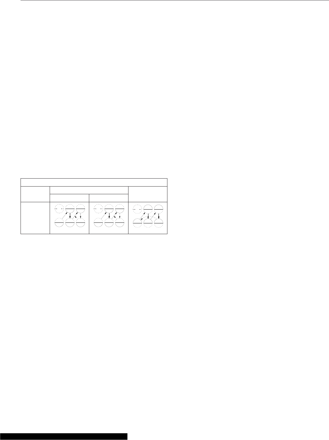
6. Double-clutch between all upshifts and down-
shifts.
7. After your shifting ability improves, you may want
to skip some of the ratios. This may be done
only when operating conditions permit, depend-
ing on the load, grade, and road speed.
Upshifting
1. Position the gear shift lever in neutral. Start the
engine, and bring the air system pressure up to
100 to 120 psi (689 to 827 kPa).
2. Position the range preselection lever down, into
low range.
3. Press the clutch pedal to the floor; shift into low
or 1st gear (Table 14.1), then engage the clutch,
with the engine at or near idle speed, to start the
vehicle moving. Accelerate to 80 percent of en-
gine governed speed.
Eaton Fuller Shift Progressions
TRANS.
MODEL
LOW RANGE HIGH
RANGE
Off-Highway On-Highway
10-Speed
Direct or
Overdrive
(RT or
RTX)
2
3
4
1
f260329
R
5
2
3
4
1
f260329
R
5
9
810
7
f260330
R
6
Table 14.1, Eaton Fuller Range-Shift Shift
Progressions
4. Shift progressively upward from low or 1st gear,
to the top gear in low range (Table 14.1),
double-clutching between shifts, and accelerating
to 80 percent of engine governed speed.
5. While in the top gear of the low range shift pat-
tern, and ready for the next upshift, flip the range
preselection lever up into high range. Double-
clutch through neutral, and shift into the bottom
gear in high range (Table 14.1). As the shift lever
passes through neutral, the transmission will au-
tomatically shift from low range to high range.
6. With the transmission in high range, shift pro-
gressively upward through each of the high
range gears (Table 14.1), double-clutching be-
tween shifts.
Downshifting
1. With the transmission in high range, shift pro-
gressively downward to the bottom gear in high
range, double-clutching between shifts.
2. When in the bottom gear of the high range shift
pattern, and ready for the next downshift, push
the range preselection lever down into low range.
Double-clutch through neutral, and shift into the
top gear of the low range shift pattern. As the
shift lever passes through neutral, the transmis-
sion will automatically shift from high range to
low range.
3. With the transmission in low range, downshift
through the low range gears as conditions re-
quire.
IMPORTANT: Never use the clutch brake when
downshifting, or as a brake to slow the vehicle.
Clutch
General Information
The hydraulic clutch control system consists of a
pedal unit and a slave cylinder, connected by a hy-
draulic hose and fastened with quick-disconnect
clamps. The components of the system have been
specially designed to use DOT 4 brake fluid. The
pedal unit includes a hydraulic subassembly, com-
posed of the master cylinder and reservoir, which
can be removed from the pedal unit for service pur-
poses. When the clutch pedal is depressed, the fluid
in the master cylinder is forced through a hydraulic
line to the slave cylinder. The fluid pressure moves
the slave cylinder piston, pushing the plunger rod
and clutch release lever, which disengages the
clutch. The hydraulic system is self-adjusting.
Clutches are designed to absorb and dissipate more
heat than encountered in typical operation. The tem-
peratures developed in typical operation will not
break down the clutch friction surfaces. However, if a
clutch is slipped excessively, or asked to do the job
of a fluid coupling, high temperatures develop quickly
and destroy the clutch. Temperatures generated be-
tween the flywheel, driven discs, and pressure plates
can be high enough to cause the metal to flow and
the friction facing material to char and burn.
Heat and wear are practically nonexistent when a
clutch is fully engaged. But during the moment of
engagement, when the clutch is picking up the load,
Manual Transmissions and Hydraulic Clutch
14.5
it generates considerable heat. An improperly ad-
justed or slipping clutch will rapidly generate suffi-
cient heat to destroy itself.
To ensure long service life of the clutch; start in the
right gear, be alert to clutch malfunctions, and know
when to adjust the clutch.
Clutch Operation
Clutch Break-In
With a new or newly installed clutch, the clutch may
slip for a short time while the friction surfaces break-
in. However, allowing the clutch to slip for more than
two seconds can severely damage the clutch disc,
pressure plate, and the flywheel.
During initial operation of a new vehicle or a vehicle
with a new clutch, check for clutch slippage during
acceleration. If the clutch slips, decelerate until the
clutch does not slip. Allow the clutch to cool 15 to 30
seconds, and then gradually accelerate again. If the
clutch continues to slip, repeat the procedure. If nec-
essary, repeat the procedure up to five times. If the
clutch slips after five attempts, stop the vehicle. Allow
the clutch to cool for at least one hour. Notify your
Freightliner dealer of the problem.
CAUTION
Do not allow sustained slippage of the clutch;
this could severely damage the clutch disc, pres-
sure plate, or flywheel. Damage caused by clutch
slippage due to improper break-in is not warrant-
able.
Moving the Vehicle in the Proper Gear
An empty truck can be started in a higher transmis-
sion gear than can a partially or fully loaded truck. A
good rule of thumb for the driver to follow is to select
the gear combination that allows the vehicle to start
moving with an idling engine, or, if necessary, just
enough throttle to prevent stalling the engine. After
the clutch is fully engaged, the engine can be accel-
erated to the correct rpm for the upshift into the next
higher gear.
Gear Shifting Techniques
Shift into the next higher gear when the vehicle
speed allows the transmission input shaft speed to
match the flywheel speed when engaging the clutch.
This technique results in the smallest speed differ-
ence between the clutch disc and the flywheel and
causes the least heat and wear on the clutch assem-
bly. When downshifting, the input shaft speed must
be increased by slightly revving the engine to match
the flywheel speed for smooth clutch engagement.
For transmission operating instructions, refer to the
transmission headings in this manual.
Vehicle Loading
Clutches are designed for specific vehicle applica-
tions and loads. These weight limitations should not
be exceeded.
CAUTION
Exceeding vehicle load limits can not only result
in damage to the clutch, but can also damage the
entire powertrain.
Using the Clutch
The clutch pedal must be used only to start the ve-
hicle moving or while shifting. To start the vehicle
moving, depress the clutch pedal all the way to the
floor plate (see "Using the Clutch Brake") and shift
from neutral to a low gear. Slowly raise your foot until
the clutch starts to engage. In this position the clutch
is starting to connect the transmission input shaft to
the flywheel and is causing the most heat and wear.
Slightly increase the engine speed and smoothly
allow the clutch pedal to return to its at rest position.
Do not allow the clutch to remain in the partially en-
gaged position any longer than necessary to obtain a
smooth start.
To shift gears while the vehicle is moving, push the
clutch pedal most of the way (but not all of the way)
to the floor plate. Shift the transmission into neutral
and fully release the clutch pedal. If upshifting, wait
long enough for the engine speed to decrease to the
road speed. If downshifting, increase the engine
speed to match the road speed. Again, push down
the clutch pedal part way and then move the shift
lever to the next gear position. Fully release the
clutch pedal after completing the shift.
Slightly depressing the clutch pedal while driving is
damaging to the clutch, because partial clutch en-
gagement causes slippage and heat. Resting your
foot on the clutch pedal will also put a constant thrust
load on the release bearing, thinning the bearing lu-
bricant and increasing the wear on the bearing.
Manual Transmissions and Hydraulic Clutch
14.6
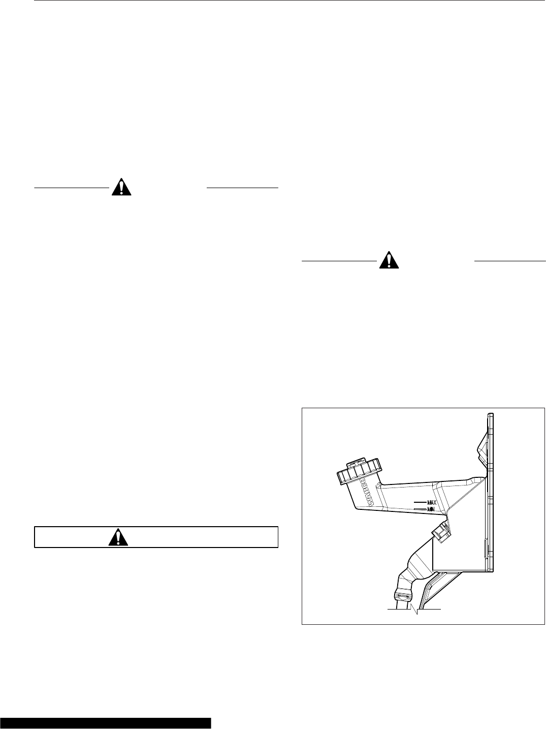
Using the Clutch Brake
The clutch brake is applied by depressing the clutch
pedal past the fully released clutch position, almost
to the floor plate. The last part of the clutch pedal
travel will compress the clutch brake plates together,
stopping the transmission input shaft. The purpose of
the clutch brake is to stop the transmission gears
from rotating in order to quickly engage a transmis-
sion gear after idling in neutral.
CAUTION
Never apply the clutch brake when the vehicle is
moving. If the clutch brake is applied when the
vehicle is moving, the clutch brake will try to
stop or decelerate the vehicle, causing rapid
wear of the clutch brake friction discs. Consider-
able heat will be generated, causing damage to
the release bearings and the transmission front
bearings.
Holding the Vehicle on an Incline
Always use the vehicle service brakes to prevent the
vehicle from rolling backwards while stopped on a
hill. Slipping the clutch on a hill to maintain the ve-
hicle position will quickly damage the clutch assem-
bly.
Coasting
Coasting with the clutch pedal depressed and the
transmission in a low gear can cause high driven
disc speed. The clutch speed can be much higher
under these conditions than when the engine is driv-
ing the clutch. This condition creates a hazardous
situation due to the lack of vehicle control and due to
the high clutch disc speed. Engaging the clutch
under these conditions can cause component dam-
age because of the shock loads to the clutch and
drivetrain.
WARNING
Always shift into the gear that is correct for the
traveling speed of the vehicle and engage the
clutch. Coasting with the clutch disengaged can
prevent engagement of the correct transmission
gear which can cause loss of vehicle control,
possibly resulting in personal injury or property
damage.
High clutch disc speeds while coasting can also
cause the clutch facing to be thrown off the disc.
Flying debris from the clutch can cause injury to
persons in the cab.
Clutch Maintenance
Clutch Adjustment
Eaton Fuller Solo clutches are adjustment-free. As
the clutch wears, its wear-adjusting technology moni-
tors clutch components and makes any necessary
adjustments. The wear adjusting technology comes
from two sliding cams, which rotate to maintain the
proper adjustment. Atop the upper cam, a wear indi-
cating tab mirrors the cam’s movement, letting you
know when it’s time to replace the clutch.
CAUTION
Operating the vehicle with incorrect free pedal
could result in clutch damage.
Hydraulic Clutch Fluid Reservoir
Checking
Make sure that the clutch fluid reservoir is full. See
Fig. 14.4. The reservoir is full when the fluid level is
up to the "max" mark. The fluid level must always be
above the "min" mark. Use only heavy-duty brake
fluid, DOT 4, in the clutch hydraulic system.
06/05/2007 f250664
Fig. 14.4, Clutch Fluid Reservoir
Manual Transmissions and Hydraulic Clutch
14.7

15
Automated Transmissions
Detroit™Automated Transmissions .................................................. 15.1
Freightliner SmartShift Shift Control ................................................. 15.5
Eaton Fuller UltraShift ............................................................ 15.6
Eaton Fuller AutoShift Automated Transmissions ...................................... 15.11
Eaton Fuller UltraShift PLUS ...................................................... 15.14
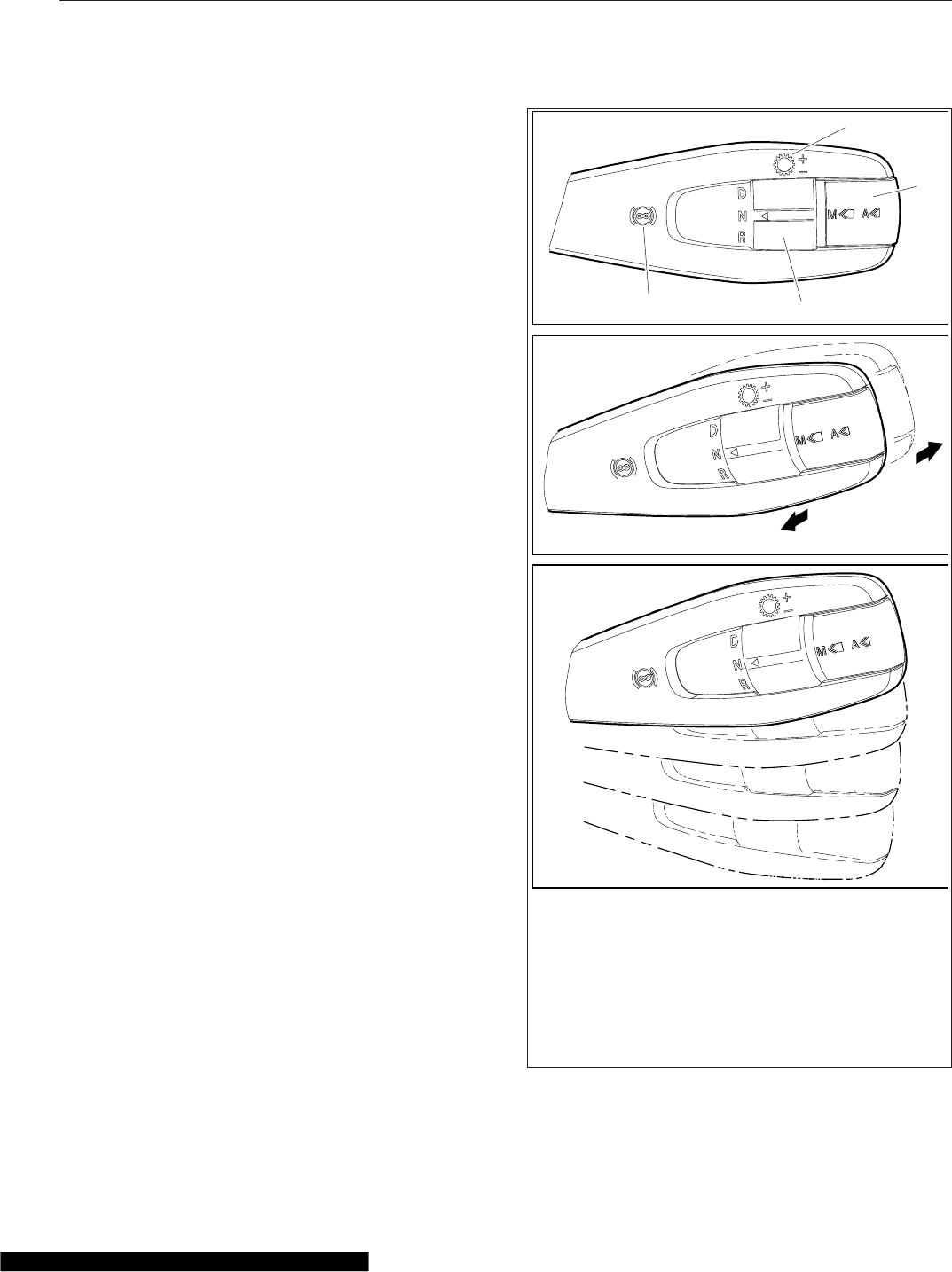
Detroit™Automated
Transmissions
Detroit transmissions have twelve forward gears and
up to four reverse gears that can be shifted automati-
cally or manually. Shifting and clutch actuation are
computer controlled, and there is no clutch pedal
needed to operate the vehicle. Automatic shifts are
selected for fuel economy or engine power. Manual
shifts can be requested with the shift control and the
transmission ECU grants them when conditions per-
mit. In all cases, shifts depend on the following fac-
tors: engine speed, accelerator pedal position, ser-
vice brake usage, engine brake operation, vehicle
load status, and road conditions.
NOTE: To avoid potential engine stall risk or un-
expected shifting, use the interaxle differential
lock when the vehicle is operated in slippery
conditions. See Chapter 16 for information
about the interaxle differential lock.
Detroit™Multifunction Control
Vehicles with Detroit transmissions use the control
shown in Fig. 15.1. This control can be used to re-
quest manual shifts, change driving mode, and set
engine brake levels. See Table 15.1 for an overview
of control functionality.
D/N/R Switch
Use the "D/N/R Switch" to request drive (D), neutral
(N), or reverse (R).
Mode Switch
The driving mode can be changed using the Mode
switch on the shift control (see Fig. 15.1). To activate
the manual drive mode, press and hold the switch
briefly. Press the switch quickly to activate the auto-
matic drive mode or change between Automatic
Economy and Automatic Performance modes.
Upshifting and Downshifting
Gear shifts can be requested manually; push the
lever away to request a downshift, or pull the lever
toward you to request an upshift. See Table 15.1 for
more information about upshift and downshift
requests.
B
2
3
1
( + )
( − )
4
05/30/2012 f270163a
A
C
See Table 15.1 for a description of control functionality.
A. Front View
B. Shift Requests
C. Four positions for engine brake settings
1. Engine Brake Symbol
2. D/N/R Switch
3. Mode Switch
4. Gear Shift Symbol
Fig. 15.1, Detroit Multifunction Control
Automated Transmissions
15.1
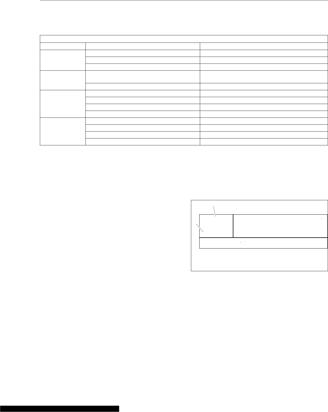
Functionality, Detroit Multifunction Control
Function/Switch Action/Position Request
D/N/R
D Forward gears
N Neutral
R Reverse gears
Mode Depress switch and release it quickly Activate the automatic drive mode, or switch between
Automatic Economy and Automatic Performance.
Depress switch and hold it briefly Activate the manual drive mode.
Upshifting and
Downshifting
Pull the lever toward you momentarily Upshift, single gear
Pull the lever toward you in quick repetitions Upshift, multiple gears
Push the lever away momentarily Downshift, single gear
Push the lever away in quick repetitions Downshift, multiple gears
Engine Brake*
Lever at position 0 (top) Engine brake off
Lever at position 1 Low intensity
Lever at position 2 Medium intensity
Lever at position 3 (bottom) High intensity
*For functions with cruise control active, see Chapter 5.
Table 15.1, Functionality, Detroit Multifunction Control
Engine Brake
The engine brake is controlled by the lever position
(as shown in Fig. 15.1, Ref. C). At the top position,
the engine brake is off, and at the three lower posi-
tions, the engine brake is on and the intensity (low,
medium, high) increases with each step down. For
more information about using the engine brake, see
Chapter 13.
NOTE: Using the engine brake with cruise con-
trol can be used to activate Descent Control
Mode or Deceleration Mode. For more informa-
tion, see "Cruise Control" in Chapter 5.
Power Up and Shift into Gear
1. With the parking brake set and Neutral (N) se-
lected on the shift control, turn the ignition switch
to the ON position.
2. Start the engine.
3. Apply the service brake.
4. Select the desired starting gear.
5. Release the parking brake.
6. Release the service brake and apply the accel-
erator.
Gear Display Window
The gear display window shows the current transmis-
sion gear and driving mode. See Fig. 15.2.
Driving Modes
There are three driving modes: Manual, Automatic
Economy, and Automatic Performance.
In Automatic Economy mode, gear shifts are de-
signed for saving fuel. In Automatic Performance
mode, gear shifts are designed for higher perfor-
mance and are made at higher engine speeds. In
manual mode, gear shifts are requested manually.
See Chapter 5 for more information about upshifting
and downshifting using the control.
5
A econ
07/09/2012 f611187
1
2
N
70 °F
1. Driving Mode
2. Current Gear
Fig. 15.2, Gear Display Window
Automated Transmissions
15.2
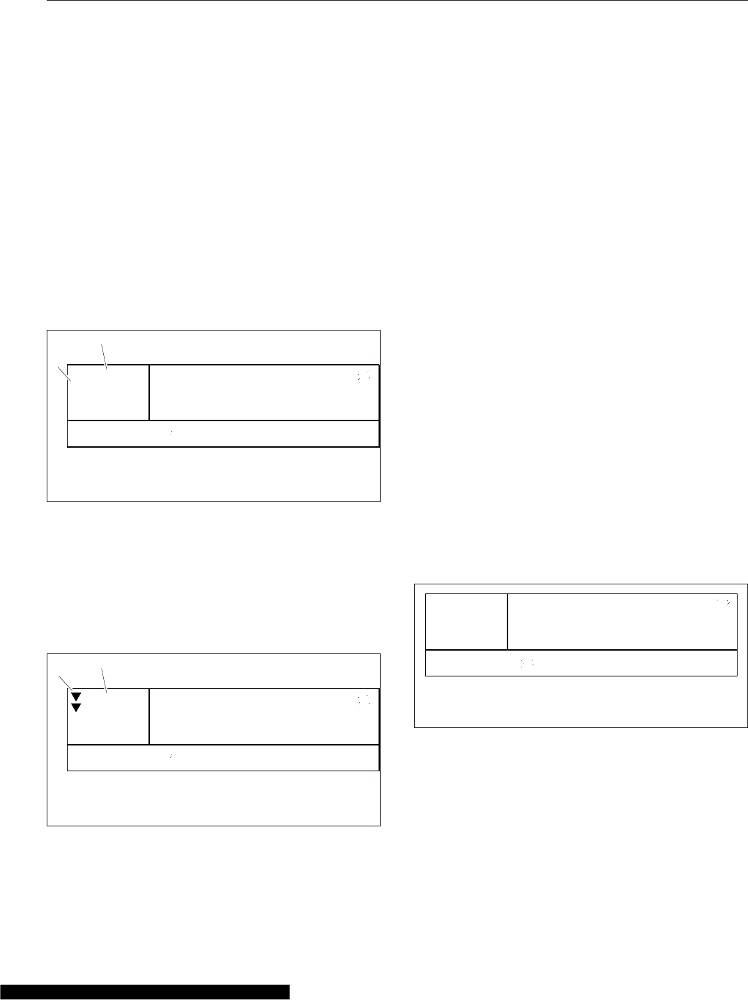
NOTE: In Automatic Performance mode, the
transmission will automatically change to Auto-
matic Economy mode if it hasn’t received a re-
quest for more power in several minutes, unless
current road conditions require higher engine
performance.
Selected Gear
If the selected gear is different than the current gear
for longer than a half second, the current gear dis-
play will flash and the selected gear value will be
shown. Once the current gear and selected gear
match, the selected gear display disappears and the
current gear display stops flashing. See Fig. 15.3.
Suggested Shift
In Manual mode only, a suggested shift is displayed
to indicate the most economical gear available. The
suggested shift is the number of up or down arrows
from the current gear with a maximum of three up or
down arrows. See Fig. 15.4.
eCoast
The eCoast feature can improve driving economy.
When conditions permit, the transmission control au-
tomatically shifts the transmission to neutral to coast
at speeds of approximately 22 mph (35 km/h) and
above. An "E" shows in the gear display window
when eCoast is in effect. See Fig. 15.5.
The eCoast function is not active when any of the
following occur:
•the accelerator pedal is pressed.
•vehicle acceleration rate is exceeded.
•the service brake pedal is pressed.
•the engine brake is in use.
•cruise control brakes or accelerates.
•vehicle speed exceeds the cruise control set
speed by more than approximately 4 mph (6
km/h).
•the speed limiter is active and the maximum
speed set is exceeded.
•diesel particulate filter (DPF) regeneration oc-
curs.
The eCoast function cannot be deactivated when the
Automatic Economy mode is active.
NOTE: To disable eCoast, see an authorized
Freightliner service facility.
Creep Mode
Creep mode allows the vehicle to be maneuvered at
very slow speeds. To activate Creep mode for the
first time within the current driving cycle, press the
accelerator pedal to launch the vehicle, thereby fully
07/09/2012 f611188
1
2
7
A econ
5N
70 °F
1. Selected Gear
2. Current Gear
Fig. 15.3, Selected Gear Display
Manual
07/09/2012 f611189
12
5N
70 °F
1. Suggested Shift Arrows
2. Current Gear
Fig. 15.4, Suggested Shift
E
07/09/2012 f611190
A econ
N
70 °F
NOTE: Upshift and downshift arrows are not shown
when "E" is shown in the gear display window.
Fig. 15.5, eCoast Display
Automated Transmissions
15.3

engaging the clutch. Following this and for the dura-
tion of the current driving cycle, Creep mode is ac-
tive.
Once the vehicle is stopped via the service brakes,
the vehicle will begin to creep again, without the ac-
celerator pedal actuation, as soon as the service
brakes are released.
To begin using Creep mode (once active) from a
parked position, shift from neutral to either drive or
reverse, release the service brakes, and briefly de-
press the accelerator pedal. The vehicle’s urge to
move can then be felt.
If creep is active and no acceleration is achieved
within five seconds, then Creep mode will abort. A
display message notifies the operator when Creep
mode is about to be aborted.
IMPORTANT: When slowing down from higher
speeds in drive or reverse, remember that
Creep mode will be in effect at lower speeds.
Use the service brakes to stop the vehicle.
Clutch Abuse Protection
A vehicle equipped with a Detroit transmission does
not have a clutch pedal, but still has a clutch that is
operated automatically and can be damaged by abu-
sive driver actions. To protect the clutch, the vehicle
has a clutch abuse protection system that alerts the
driver and restricts functionality when needed. Ex-
tended periods in Creep Mode, slipping the clutch
(using the accelerator pedal to hold the vehicle on a
hill, for example), and high clutch temperatures can
activate the clutch abuse protection system. A display
message notifies the operator when the protections
are needed.
NOTICE
To hold the vehicle stationary on an uphill slope,
use the service brakes, not the accelerator pedal.
Using the accelerator pedal can overheat and
damage the clutch. To start moving, use the ac-
celerator pedal and release the brakes as the ve-
hicle begins to move.
There are three clutch abuse protection levels. At
each, the driver is alerted and functionality is modi-
fied; see Table 15.2.
To avoid clutch overheating, follow these tips:
•To hold the vehicle stationary on an uphill
slope, use the service brakes, not the accel-
erator pedal.
•To start moving on an uphill slope, use the ac-
celerator pedal and release the brakes as the
vehicle begins to move.
•When hooking up to a trailer, ensure the trailer
is high enough to back under, and use first
gear reverse.
•Avoid starting in higher gears, and start in first
gear when a trailer is attached.
•Ensure trailer brakes have had time to com-
pletely release prior to starting.
•Do not use Creep mode for an extended pe-
riod. Stop or adjust the vehicle speed when
warned to deactivate Creep mode.
Engine Overspeed Alerts
To help protect the engine, the system has display
messages to notify the operator when the engine has
exceeded certain thresholds and needs to be slowed
down before significant engine damage occurs.
There are two warnings, one at about 2400 rpm and
another at 2500 rpm, indicated with messages and a
fault code.
Low Transmission Air Warning
Pneumatic controls are used to shift the transmis-
sion. If there is inadequate air pressure, a warning is
displayed and the quality of gear shifts may be de-
graded. Wait for air pressure to build before operat-
ing the vehicle.
IMPORTANT: If the low transmission air warning
indicator appears while the vehicle is in opera-
tion, safely pull the vehicle off the road, and cor-
rect the problem.
Clutch Abuse Alerts and Protections
Alert Level Alert Protections
Highest Start Gear Creep Mode Clutch Function
1 Heavy clutch load message 1 No restriction Normal function
Automated Transmissions
15.4
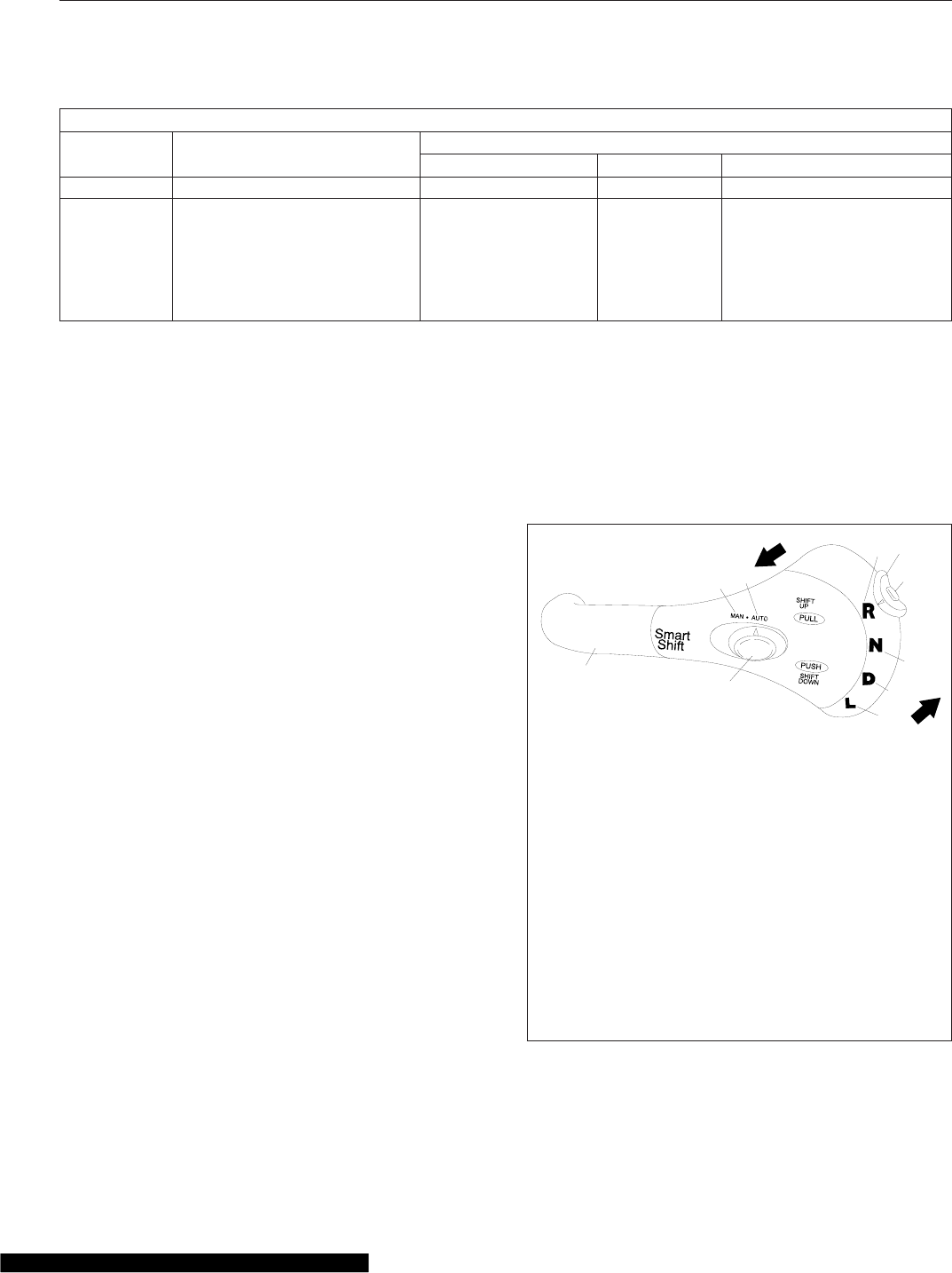
Clutch Abuse Alerts and Protections
Alert Level Alert Protections
Highest Start Gear Creep Mode Clutch Function
2 Heavy clutch load message 1 Disabled Normal function
3Clutch overload message and
buzzer 1 Disabled
If the accelerator pedal is
depressed, the clutch closes
at fixed rate.
If the accelerator pedal is
released, the clutch opens at
fixed rate.
Table 15.2, Clutch Abuse Alerts and Protections
Freightliner SmartShift Shift
Control
General Information, SmartShift
The SmartShift transmission control is an electronic
transmission control device. It is installed with the
following transmissions:
•Eaton Fuller UltraShift™
•Eaton Fuller UltraShift™PLUS
•Eaton Fuller AutoShift™
It replaces the typical floor-mounted shift lever or
dash-mounted push button control.
SmartShift accepts driver requests for transmission
functions and transmits them through hard wiring to
the transmission control unit (TCU). SmartShift is a
true shift-by-wire system.
SmartShift offers two main advantages over conven-
tional transmission control devices. Without a floor-
mounted shift control, usable cab space is increased.
The SmartShift control mounts to the right-hand side
of the steering column and is operated by the fingers
of the driver’s right hand, allowing both hands to re-
main on the steering wheel.
A two-position slide switch (Fig. 15.6) is mounted on
the body of the control lever just before the paddle
widens out. The slide switch allows the driver to
choose automatic (AUTO) or manual (MAN) mode.
In AUTO mode, gears shift automatically, without
driver interaction. Manual gearshifts are accom-
plished by a momentary pull or push on the control in
the plane perpendicular to the steering wheel. Pull
upward (toward you) on the control to upshift and
push downward (away from you) to downshift. The
control is spring-loaded and returns to mid-position
when released after an upshift or downshift.
For Eaton Fuller UltraShift, UltraShift PLUS, and Au-
toShift transmissions (Fig. 15.6), a four-position (R,
N, D, L) selector switch is located at the end of the
lever.
01/24/2003
12
34
56
8
9
10
11 12
f270120
7
To upshift manually, pull the lever up (towards you). To
downshift manually, push the lever down (away from
you).
1. SmartShift Control Lever
2. Slide Switch (forward driving mode switch)
3. MAN Mode (of slide switch)
4. AUTO Mode (of slide switch)
5. Upshift Direction
6. Reverse Position (of selector switch)
7. Selector Switch
8. Neutral Lock Button
9. Neutral Position (of selector switch)
10. Drive Position (of selector switch)
11. Low Position (of selector switch)
12. Downshift Direction
Fig. 15.6, SmartShift Control (Eaton Fuller UltraShift,
UltraShift PLUS, and AutoShift Transmissions)
Automated Transmissions
15.5
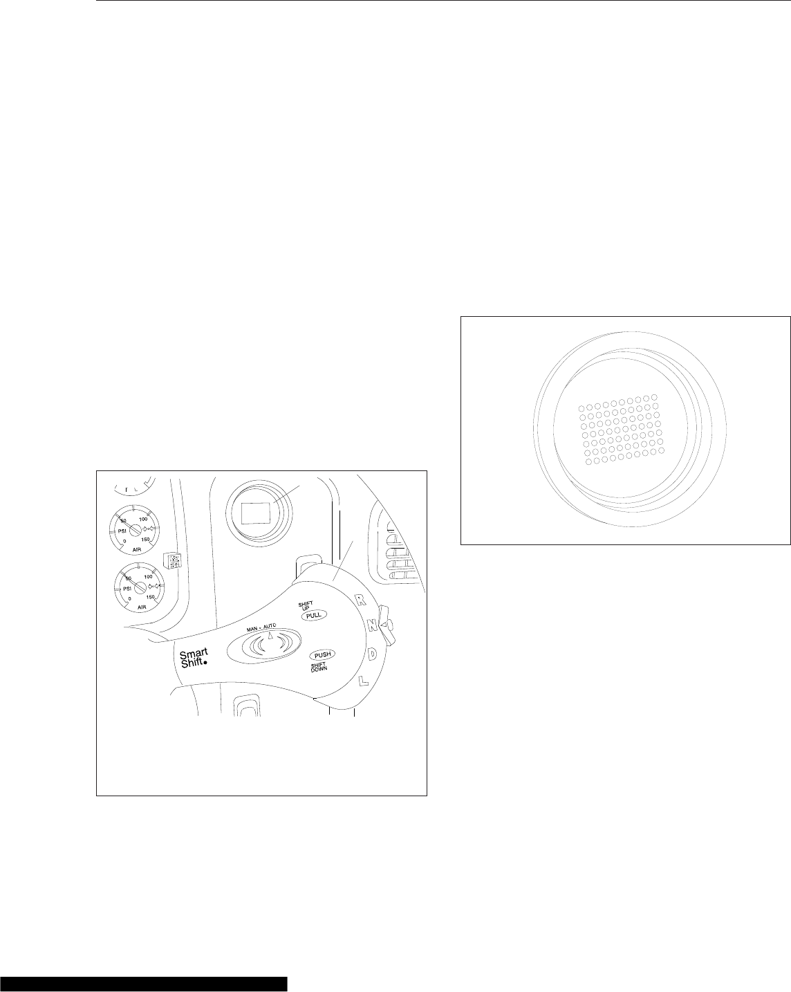
Embedded in the selector switch is a small neutral
lock button to prevent accidental shifts into gear from
neutral. Any time you shift through N, press down on
the neutral lock button to move the switch from neu-
tral (N) to another gear, such as drive (D), low (L), or
reverse (R). When shifting to N, it is not necessary to
press the neutral lock button.
Eaton Fuller UltraShift
General Information, UltraShift DM
Eaton® Fuller® UltraShift™DM is a ten-speed heavy-
duty fully automated transmission. No clutch pedal is
required to operate the vehicle.
UltraShift DM uses a dry clutch system which is of-
fered only on this automated transmission system.
The UltraShift transmission uses the four-position
SmartShift lever on the steering column to select
gears. To know what gear the transmission is in, look
at the round current gear indicator on the right-hand
control panel as shown in Fig. 15.7. All forward shifts
can be made either manually or automatically, at the
driver’s choice.
Operation, UltraShift DM
Power Up
1. With the parking brake set, select neutral (N) by
moving the selector switch to the N position.
2. With the transmission in neutral, turn on the igni-
tion switch. The CHECK TRANS and TRANS
TEMP telltale lights come on and go out again
(bulb check).
3. After the ignition is turned on, the current gear
indicator shows the dot display, arranged in a
square pattern. All dots in the pattern should light
up, without gaps or spaces. See Fig. 15.8.
4. Wait for the current gear indicator to show a solid
N. When the N is solid, rather than flashing, the
UltraShift DM TCU is powered up. Apply the ser-
vice brake and start the engine.
5. Select drive (D) by pressing in the neutral lock
button and moving the selector switch downward
to the position below neutral. Release the park-
ing brake. The gear is displayed on the current
gear indicator.
NOTE: When D is selected, the transmission
controller starts up in second gear. If desired,
the driver can select to start up in first. No other
start gear is available.
6. On a level grade, release the service brake and
press down on the throttle pedal to allow the ve-
hicle to move forward. The vehicle will not move
until the pedal is depressed.
12/22/2003 f270079a
1
2
To know what gear the transmission is in, look at the
current gear indicator.
1. Current Gear Indicator
2. SmartShift Control
Fig. 15.7, Shift Controls and Indicators, UltraShift
Transmissions
10/13/2003 f610678
Fig. 15.8, Power-Up Dot Display
Automated Transmissions
15.6
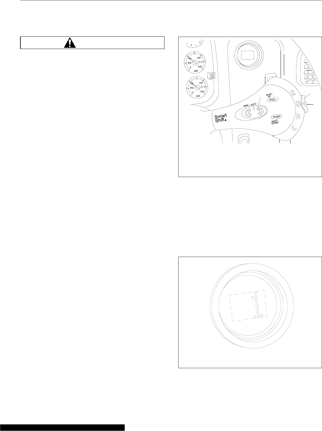
WARNING
When starting or stopping on hills and grades,
use extra care to prevent the vehicle from rolling
back. A rollback accident could cause death, seri-
ous personal injury, or property damage.
7. Prevent the vehicle from rolling backwards when
stopped on a hill or grade, or when the vehicle is
starting from a stop on a hill or grade.
7.1 To start from a full stop on a hill or grade,
quickly move your foot from the brake
pedal and press firmly on the throttle
pedal.
On steep hills, set the parking brake, and
release it only when there is enough en-
gine power to prevent rollback.
7.2 To stop on a hill or grade, press and hold
the brake pedal to keep the vehicle from
moving.
On steep hills, set the parking brake.
When parking, chock the tires, front and/or
rear. Never hold a hill with the throttle
pedal. This will cause the clutch to over-
heat.
Power Down
1. Apply the service brakes.
2. Select neutral (N) by pressing in the neutral lock
button and moving the selector switch to N.
When the N on the current gear indicator is solid,
rather than flashing, the UltraShift DM TCU is
ready to power down.
3. With the transmission in neutral, set the parking
brake.
4. Turn off the ignition key and shut down the en-
gine.
Automatic and Manual Modes
The SmartShift control has a slide switch located on
the body of the control lever just before the paddle
widens out. See Fig. 15.9. The slide switch controls
the forward driving mode, automatic or manual.
To change mode at any time, move the slide switch
in the desired direction. This allows the driver to re-
spond to a wide range of driving conditions, such as
blind corners, tight curves, and steep hills.
IMPORTANT: Whatever the mode, it is always
possible to shift manually by moving the lever
up or down as needed. When the engine speed
is within 75 revolutions per minute (rpm) of the
load-based shift point for an automatic shift, the
UltraShift DM TCU will advance the shift.
In either mode, the gear indicator displays the cur-
rent gear. See Fig. 15.10.
01/21/2004 f270079c
12
3
1. Slide Switch (controls forward driving mode)
2. Selector Switch (controls gear selection)
3. Neutral Lock Button (prevents accidental shift into
gear)
Fig. 15.9, Switches, UltraShift Transmissions
10/13/2003 f610680
NOTE: The gear indicator displays the current gear. In
this example, it displays first gear.
Fig. 15.10, Current Gear Display
Automated Transmissions
15.7

At the start of a shift, the current gear continues to
display until the transmission has been pulled into
neutral. At this point, as the transmission is synchro-
nizing for the new (target) gear, the gear indicator
flashes the number of the new gear.
When the shift is complete, the new gear displays
solid, without flashing.
Automatic Mode (AUTO)
In automatic drive mode (AUTO), upshifts and down-
shifts are made by the transmission without driver
intervention. Press in the neutral lock button, move
the selector switch to drive (D), and press down on
the throttle pedal. The transmission will shift auto-
matically.
If driving conditions require, it is still possible to re-
quest a manual shift. The transmission will make the
shift if the engine speed is within 75 rpm of the load-
based shift point for that gear.
If the driver presses down on the throttle pedal after
a manual downshift in automatic mode, the transmis-
sion will upshift again if the UltraShift DM TCU re-
quires it.
Manual Mode (MAN)
In manual drive mode (MAN), upshifts and down-
shifts are made by the driver:
•To shift up, pull the lever up (towards you).
•To shift down, push the lever down (away from
you).
The system will hold the current gear until the driver
requests a shift. In downhill situations in particular,
the driver must be alert to vehicle speed by down-
shifting and/or using the service brakes as needed.
A shift request will still be refused if the selected gear
would cause engine overspeed or excessive lugging.
Selecting Gears
Reverse
Reverse (R) is at the upper end of the four-position
selector switch located at the end of the SmartShift
control lever. To select R, press in the neutral lock
button and move the selector switch upward to the
position above neutral.
UltraShift DM has two reverse gears, reverse low
and reverse high. To shift manually between them,
use the shift lever as described for MAN mode.
There is no AUTO mode for reverse.
When reverse low is selected, the letter R displays
on the current gear indicator. When reverse high is
selected, the letter H displays on the current gear
indicator. See Fig. 15.11.
IMPORTANT: Under normal conditions, do not
select reverse with the vehicle moving forward.
The vehicle must be moving at less than two miles
per hour (3 km/h) before selecting reverse. If reverse
is selected when the vehicle is moving faster, an au-
dible alert will sound and continue sounding at three-
second intervals until the control lever is returned to
the D position or the vehicle slows to the proper
speed.
If necessary to rock the vehicle, use the selector
switch to shift back and forth at low speed between
reverse and drive.
Neutral
IMPORTANT: Always start the engine with the
transmission in neutral, the parking brake set,
and the service brakes applied.
Neutral (N) is directly below R on the four-position
selector switch located at the end of the SmartShift
control lever. To select N, press in the neutral lock
button and move the selector switch to the position
below R. When neutral is selected, the letter N dis-
plays on the current gear indicator. See Fig. 15.12.
10/14/2003 f610681
Fig. 15.11, Reverse Gear Display
Automated Transmissions
15.8
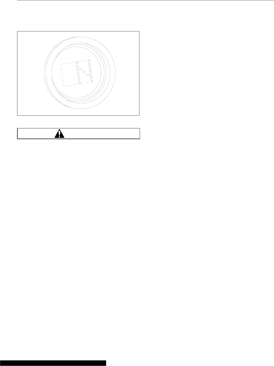
WARNING
Do not coast in neutral. Coasting in neutral can
cause an accident, possibly resulting in severe
personal injury or death.
Neutral is always available during operation, what-
ever the vehicle speed. When in neutral, requests to
upshift or downshift are ignored. If the selector switch
is moved from neutral to drive while the vehicle is
moving, the transmission will shift into a gear within
the engine’s operating speed range.
When shifting from neutral, always press on the
brake pedal. If the brake pedal is not pressed, the
transmission will not shift, the current gear display
will flash N, and an audible alert will sound.
NOTE: To reset the transmission, return the se-
lector switch on the SmartShift lever to N and
attempt the shift again, this time with the brake
pedal pressed.
Before shutting down the engine, return the selector
switch to N. When the ignition is turned off, the trans-
mission will reset to neutral in a few minutes regard-
less of the position of the shift lever.
Drive
Drive (D) is directly below N on the four-position se-
lector switch located at the end of the SmartShift
control lever. To select D, press in the neutral lock
button and move the selector switch to the position
below N. When drive is selected, the number of the
currently selected forward gear (1 through 10) dis-
plays on the gear indicator. See Fig. 15.10.
When in drive, requests to upshift or downshift are
enabled. Either manual or automatic mode can be
selected on the slide switch.
Two starting gears are available, first and second.
The default starting gear is second, but first can be
selected by the driver, if desired. To change the start-
ing gear, press the brake pedal and select D with the
vehicle stopped. The current gear indicator will dis-
play the starting gear. Move the shift lever up or
down until the desired starting gear is displayed.
The UltraShift DM TCU adapts to the working condi-
tions of each vehicle and its driver. After power up or
a load change, it needs to learn the new conditions.
While learning, it may hold a gear too long before
upshifting. Start the upshift manually. It may take
three or four shifts before UltraShift succeeds in
learning the new load-based shift points, but after
that it will handle the shifting automatically.
Low
Low (L) is at the lower end of the four-position selec-
tor switch located at the end of the SmartShift control
lever. To select L, press in the neutral lock button
and move the selector switch to the position below
D.
When in low, the current gear is maintained. Re-
quests to upshift are not enabled.
IMPORTANT: If the engine is approaching over-
speed, the UltraShift DM TCU will override the
current gear setting and upshift to prevent en-
gine damage.
To enhance engine braking, downshifts are per-
formed at higher rpm than normal.
If L is selected from neutral while stopped, the ve-
hicle starts up in first gear and stays there until the
engine approaches overspeed.
Upshifting
To request an upshift with the transmission in drive,
pull the control lever up (towards you). If the gear is
available, the transmission upshifts and the new gear
displays on the gear indicator. No skip shifts are
available while upshifting.
No upshifts are available in low, except to prevent
engine overspeed.
10/13/2003 f610679
Fig. 15.12, Neutral Display
Automated Transmissions
15.9

If the transmission does not upshift quickly enough
after power-up or a load change, begin the shift
manually. The UltraShift DM TCU will learn the new
load-based shift conditions after three or four shifts.
If the gear requested is unavailable, a tone will
sound. An unavailable request to upshift is not stored
in memory. The upshift must be requested again.
Downshifting
NOTE: The driver can manually downshift at
any time, even when the slide switch is set to
AUTO mode.
To request a downshift with the transmission in drive
or low, push the control lever down (away from you).
If the gear is available, the transmission downshifts
and the new gear displays on the gear indicator. Skip
shifts are available while downshifting.
For best engine braking, select low while moving. In
low, downshifts are performed at higher rpm than in
drive.
IMPORTANT: If the engine is approaching over-
speed, the UltraShift DM TCU will override the
current gear setting and upshift to prevent en-
gine damage.
If the gear requested is unavailable, a tone will
sound. An unavailable request to downshift is not
stored in memory. The downshift must be requested
again.
When coasting to a stop, the UltraShift DM TCU may
not finish the downshift until the driver presses down
on the throttle pedal again.
IMPORTANT: A downshift request can never
result in a shift into neutral, even if the vehicle is
in the drive position in the lowest possible gear.
Before starting down a hill, slow down. Downshift to
a speed that you can control without hard pressure
on the service brakes.
Before entering a curve, slow down to a safe speed.
Downshift if necessary. This lets you use some
power through the curve to help the vehicle be more
stable on the turn. It also allows you to regain speed
faster as you come out of the curve.
Ultrashift Diagnostics
Clutch Protection Fault
Excessive clutch slippage creates heat and reduces
the life of the clutch. These are some conditions
which lead to clutch abuse:
•Using the throttle to hold the vehicle on a
grade
•Starting the vehicle in too high a gear
•Overloading the vehicle
•Using high idle with the vehicle in gear
The UltraShift DM TCU is programmed to prevent
clutch abuse. When the clutch overheats, the follow-
ing alerts take place:
•The TRANS TEMP light comes on
•The current gear indicator displays CA
•A warning tone sounds at one-second intervals
The alerts continue until the clutch cools, the throttle
is released, or the clutch is fully engaged.
System Problem
In the event of a problem, do the following steps.
1. Note the driving conditions at the time the prob-
lem occurred.
2. Record the status of the transmission at the time
of the problem (AUTO or MAN mode, gear set-
ting R, N, D, or L, current gear, engine speed,
etc.)
3. Reset the system, using the procedure below.
Reset Procedure
Transmission operation can sometimes be restored
by doing the following reset procedure:
1. Stop the vehicle when it is safe to do so. Set the
parking brake.
2. Place the selector switch in neutral and turn off
the ignition.
3. Check all harness connectors as described in
Chapter 21.
4. Wait at least two minutes with the engine shut
down.
5. Restart the engine.
Automated Transmissions
15.10
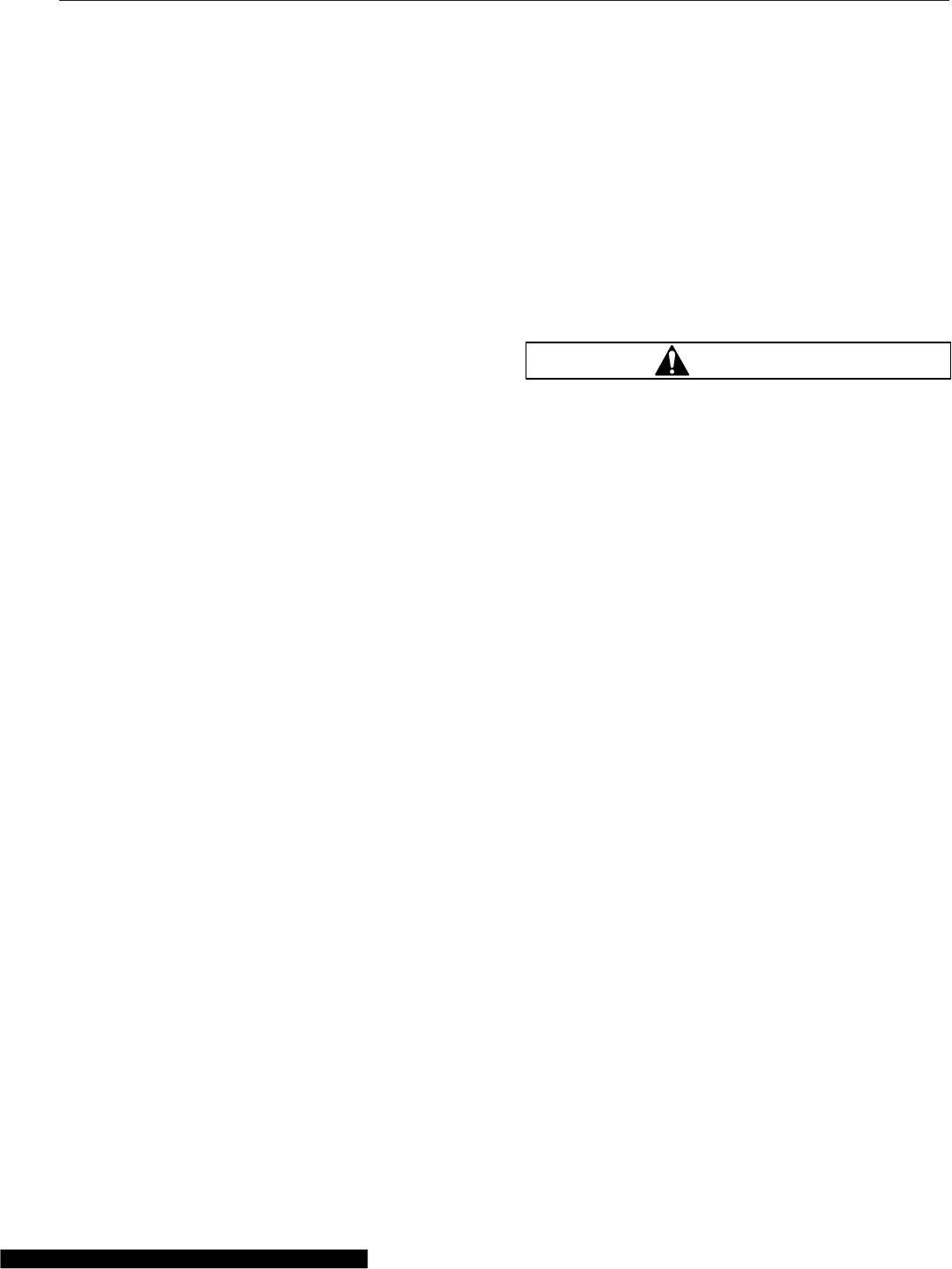
If the problem continues, contact an authorized
Freightliner or Eaton service facility.
Locked In Gear
If the transmission becomes locked in gear, a dash
(–) will appear on the current gear indicator when the
vehicle is restarted during the reset procedure.
NOTE: If the transmission becomes locked in
gear while the vehicle is moving, increased
braking effort may be required to stop the ve-
hicle.
If the current gear indicator displays a dash during
power-up with the selector switch in neutral, do the
following steps.
1. Make sure the parking brake is set.
2. Turn off the ignition and wait at least two min-
utes.
3. Apply the service brakes.
4. With the service brakes applied, release the
parking brake.
5. Make sure the selector switch is in neutral and
turn on the ignition key. Do not attempt to start
the engine at this time.
6. If necessary to get the transmission to shift into
neutral, release the pressure on the brake pedal
slightly.
7. Once the UltraShift DM TCU reaches neutral, a
solid N will appear on the current gear indicator
and the vehicle will start. Make sure the service
brakes are applied and the parking brake is set.
If the current gear indicator continues to display a
dash, contact an authorized Freightliner or Eaton ser-
vice facility.
Eaton Fuller AutoShift
Automated Transmissions
Refer to the Eaton website for additional information,
www.roadranger.com.
General Information, AutoShift
10-Speed RT/RTO Models
Eaton Fuller 10-speed AutoShift transmissions have
10 forward speeds and two reverse speeds. The
transmission consists of a 5-speed front section and
a 2-speed rear section. The driver must use the
clutch to start and stop the vehicle.
The driver does not need to break torque or increase
or decrease engine speed to synchronize the shift.
The transmission signals the engine controller when
to break torque and the engine controller automati-
cally increases or decreases engine speed. When
engine speed is correct, the transmission engages
the next gear and signals the engine controller to
resume operation.
WARNING
When starting or stopping on hills and grades,
use extra care to prevent the vehicle from rolling
back. A rollback accident could cause death, seri-
ous personal injury, or property damage.
The AutoShift system consists of the following com-
ponents:
•The SmartShift control paddle on the steering
column. See Fig. 15.6.
•The gear display module (Fig. 15.13) mounted
on the dashboard indicates the current gear
position or transmission status. The display
also flashes the next gear to be engaged while
the transmission is in neutral during a gear
change.
•The shifter mechanism performs shifts at the
front portion of the transmission. It preselects
the shift to neutral and completes the gear
change after driver input.
•The Electronic Control Unit (ECU) includes two
controllers: a transmission ECU and a system
ECU. The transmission ECU controls all trans-
mission shift functions and the system ECU
manages all vehicle interfaces for transmission
shift functions.
•An electronic range valve, controlled by the
transmission ECU, is used to perform range
shifts.
Operation, AutoShift with SmartShift
Automatic and Manual Modes
A two-position slide switch (forward driving mode
switch) is located near the end of the control
(Fig. 15.6). The switch positions are labelled MAN
Automated Transmissions
15.11
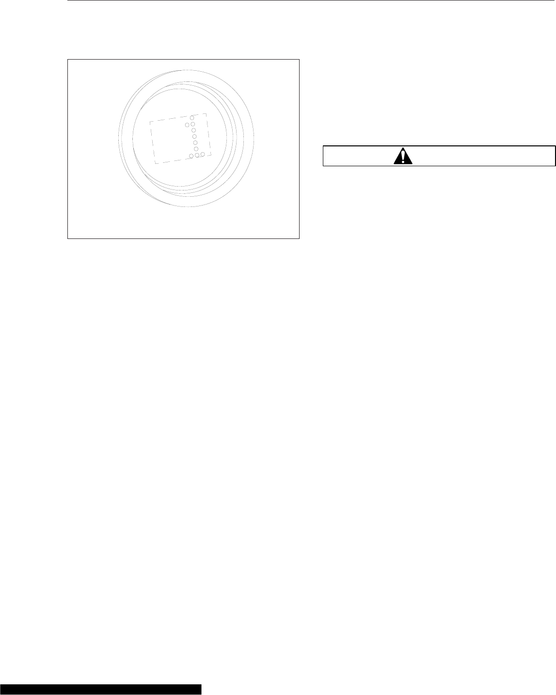
(manual shift mode) and AUTO (automatic drive
mode).
NOTE: In automatic drive mode, upshifts and
downshifts require no driver interaction. Move
the selector switch to the drive (D) position, dis-
engage the clutch to engage the gear selected,
engage the clutch and drive the vehicle. In
manual shift mode, upshifts and downshifts re-
quire either a pull upward or push downward on
the control.
Driver Message Center
Gear information is presented to the driver on the
dash display. In automatic drive mode, the number of
the forward gear currently engaged appears continu-
ally on the message display screen when in drive
(D). In manual shift mode, the current gear is dis-
played until a new gear is requested. When neutral
(N) is engaged, "N" will appear on the message dis-
play screen. When reverse (R) is engaged, either
"RL" or "RH" will appear on the message display
screen.
IMPORTANT: The information shown on the
message display screen indicates the state of
the transmission only, not the state of the
SmartShift control.
Neutral Position
Select neutral by sliding the selector switch to the
"N" position.
NOTE: Neutral is always available during opera-
tion. When in neutral, upshift and downshift re-
quests are ignored. If the mode selector switch
is moved from neutral (N) to drive (D) while the
vehicle is moving, the transmission will shift into
a gear causing the engine to go to a high torque
level, under the engine’s rated torque.
WARNING
Do not coast in neutral. Coasting in neutral can
cause an accident, possibly resulting in severe
personal injury or death.
Selecting a Starting Gear
1. In automatic mode, select drive (D) by sliding the
selector switch downward to the next position
below the neutral position.
2. Disengage the clutch to engage the gear se-
lected. Engage the clutch and drive the vehicle.
Changing the Default Starting Gear
To select a starting gear other than the default start-
ing gear, follow the instructions below.
1. Make sure the vehicle is stopped and in drive.
2. In either automatic or manual mode, pull upward
on the control (to increase), or push downward
(to decrease). Each pull upward on the control
increases the starting gear by one gear, but no
higher than fourth gear.
3. The number of the gear selected will flash on the
message display screen until the driver engages
the clutch. This gear will be stored in memory as
the default starting gear until either a different
starting gear is selected by the driver or the en-
gine is shut down.
NOTE: The transmission may also be pro-
grammed so that it is not possible to select a
starting gear other than the preprogrammed de-
fault starting gear.
Upshifting
NOTE: With the transmission in drive (D) in the
automatic mode, upshifts require no driver inter-
action.
10/13/2003 f610680
NOTE: The gear indicator displays the current gear. In
this example it displays first gear.
Fig. 15.13, Gear Display Module
Automated Transmissions
15.12

1. With the transmission in drive in the manual
mode, request an upshift by pulling upward on
the control. If the requested gear is available, the
transmission will upshift.
NOTE: A single, momentary pull upward on the
control selects the next higher gear when it is
available. Two consecutive, momentary upward
pulls will cause a skip shift when the next two
higher gears are available and conditions are
right.
2. To skip shift, move the control two times in less
than 1/2 second. The number of the gear en-
gaged will appear on the message display
screen.
NOTE: The Eaton Fuller AutoShift 18-speed
transmission is able to perform triple upshifts
when the next three higher gears are available
and conditions are right. To triple-shift this trans-
mission, move the control three times in less
than 1/2 second.
If a requested gear is not available, an audible
warning will sound and the gear display module
will indicate that the gear is not available. An
unavailable requested upshift is not stored in
memory. The upshift must be requested again.
Downshifting
NOTE: With the transmission in drive (D) in the
automatic mode, downshifts require no driver
interaction.
1. With the transmission in drive in the manual
mode, request a downshift by pushing downward
on the control. If the requested gear is available,
the transmission will downshift.
NOTE: A single, momentary push downward on
the control selects the next lower gear when it is
available. Two consecutive, momentary down-
ward pushes will cause a skip shift, when the
next two lower gears are available and condi-
tions are right.
2. To skip shift, move the control two times in less
than 1/2 second. The number of the gear en-
gaged will appear on the message display
screen.
NOTE: The Eaton Fuller AutoShift 18-speed
transmission is able to perform triple downshifts
when the next three lower gears are available
and conditions are right. To triple shift this trans-
mission, move the control three times in less
than 1/2 second.
If a requested gear is not available, an audible
warning will sound and the gear display module
will indicate that the requested gear is not avail-
able. Unlike upshifting, an unavailable requested
downshift is stored in memory and the shift will
be made when the gear is available. The time
limit for this memory is a programmable param-
eter.
Start-Up
1. With the parking brake applied, press the clutch
all the way down to the floor.
2. Start the engine.
3. Check to make sure the transmission is in neu-
tral.
4. With the transmission in neutral, release the
clutch.
NOTE: This allows the speed sensor on the
input shaft to get a reading.
5. Press down on the clutch again and release the
parking brake.
6. Select the desired starting gear.
7. Release the clutch.
Reverse
1. To engage reverse (R), slide the selector switch
upward to the next position above the neutral
position and disengage the clutch.
NOTE: AutoShift 10- and 18-speed transmis-
sions have a dual-range reverse. Reverse low
(RL) is the default reverse gear.
2. Select reverse high (RH) by pulling upward on
the control.
NOTE: Reverse may be engaged below a pro-
grammable forward speed in order to rock the
vehicle. If reverse is selected above the pro-
grammed forward speed, an audible warning will
Automated Transmissions
15.13

sound and a message indicating that the gear is
not available will appear on the message dis-
play screen.
Low Gear Operation
Use low (L) when descending steep hills and using
compression braking. Engine speed will be increased
by 200 rpm and shift points will be offset by 200 rpm.
The efficiency of the exhaust brake will be maxi-
mized.
Using the Clutch
Use the clutch to start and stop the vehicle.
Eaton Fuller UltraShift PLUS
Eaton Fuller UltraShift PLUS automated transmis-
sions use shift selection software and electric clutch
actuation; a clutch pedal is not needed to operate the
vehicle. These transmissions use the four-position
SmartShift control (see Fig. 15.6) on the steering
column to select mode, direction, neutral, low, and to
make manual shifts. To know what gear the transmis-
sion is in, see the current gear indicator on the dash.
Forward shifts can be made either manually or
automatically.
Power Up
NOTE: Engine cranking is delayed until the
transmission power-up is complete and the gear
display shows a solid "N".
1. With the parking brake set, turn the ignition
switch to the ON position.
2. Start the engine.
3. Apply the service brake.
NOTE: If the service brake is not applied while
selecting a starting gear, the initial start gear will
not be found and the driver will need to select
Neutral and press the service brake while se-
lecting the desired mode.
4. Select the desired mode and starting gear. (Inap-
propriate start gear selections are ignored to
avoid damaging the transmission.)
5. Release the parking brake.
6. Release the service brake and apply the accel-
erator.
Power Down
1. Select Neutral on the shift control.
NOTE: If the gear display does not show a solid
"N", neutral has not yet been obtained. Neutral
should always be reached before powering
down an UltraShift PLUS, except in cases of
emergency.
2. Set the parking brake.
3. Turn off the ignition, and shut down the engine.
Reverse (R)
NOTE: If attempting to select a non-Neutral
mode without applying the service brakes, the
transmission will not shift into gear. To shift into
gear, select Neutral, apply the service brakes,
and select the desired mode again. Also, the
vehicle will not engage reverse above 2 mph (3
km/h).
Reverse (R) is at the upper end of the four-position
selector switch located at the end of the SmartShift
control. To select R, press in the neutral lock button
and move the selector switch to the position above
neutral. The default Reverse gear is engaged.
NOTICE
Avoid launching the vehicle in high range.
Launching the vehicle in high range increases
the likelihood of clutch abuse and could be detri-
mental to clutch life.
Automatic Mode (AUTO)
In automatic drive mode (AUTO), upshifts and down-
shifts are made by the UltraShift PLUS without driver
intervention. Press in the neutral lock button, move
the selector switch to Drive (D), and press down on
the throttle pedal. The transmission will shift auto-
matically.
NOTE: If attempting to select a non-Neutral
mode without applying the service brakes, the
transmission will not shift into gear. To shift into
gear, select Neutral, apply the service brakes,
and select the desired mode again.
In Drive, the start gear is automatically selected. The
selected start gear can vary depending on several
Automated Transmissions
15.14

vehicle inputs such as load, grade, and axle/
transmission ratio. The start gear can be changed
using the SmartShift control, provided the selected
gear would allow the vehicle to launch without dam-
aging the transmission. If the start gear is changed
using the SmartShift control, it will be the default until
the vehicle is powered down or the selection is
changed again manually.
IMPORTANT: Prior to ascending a steep grade,
either reduce the default start gear by one
(using the SmartShift control) or apply full
throttle for the duration of the grade so the ve-
hicle maintains the proper engine and vehicle
speed during the entire grade.
In Drive, the transmission automatically performs up-
shifts and downshifts. However, when the transmis-
sion is near the shift point, the shift can be forced
using the upshift or downshift function of the Smart-
Shift control.
NOTE: The transmission may deny a shift while
ascending or descending a grade if the load of
the vehicle and grade of the terrain in combina-
tion with the drivetrain ratio and engine torque
fall outside of the acceptable range to perform a
shift. If the shift is denied, a tone will sound.
Manual Mode (MAN)
In manual mode (MAN), the driver selects upshifts
and downshifts instead of letting the UltraShift PLUS
select them automatically. Manual shifting may be
helpful when traversing a work site, railroad tracks,
or steep grades, for example. To drive forward, press
in the neutral lock button, move the selector switch to
Drive (D), and press down on the throttle pedal. To
shift up, pull the lever up (towards you); to shift
down, push the lever down (away from you). The
system holds the current gear unless a shift is re-
quested or if the system initiates a manual mode
override.
NOTE: The transmission may deny a shift while
ascending or descending a grade if the load of
the vehicle and grade of the terrain in combina-
tion with the drivetrain ratio and engine torque
fall outside of the acceptable range to perform a
shift. If the shift is denied, a tone will sound.
NOTE: If attempting to select a non-Neutral
mode without applying the service brakes, the
transmission will not shift into gear. To shift into
gear, select Neutral, apply the service brakes,
and select the desired mode again.
Manual Mode Override
The system is equipped with a manual mode over-
ride function. If the vehicle is being "back driven" (for
example, descending a grade and vehicle speed ex-
ceeds engine speed) and the engine speed is exces-
sively high, the system will upshift automatically.
Also, if the start gear is changed and it causes the
engine to lug at takeoff, the system will override the
current position and select the best available gear.
Low (L)
Low (L) is at the lower end of the four-position selec-
tor switch located at the end of the SmartShift con-
trol. Use Low when wanting to maximize engine
braking and minimize the use of the brake pedal—for
example, when driving down long grades or when
coming to a stop. To select Low, press in the neutral
lock button and move the selector switch to the L
position. The lowest available start gear will be se-
lected (the starting gear cannot be changed in Low).
If Low is selected while moving, the transmission will
not upshift (unless the system initiates a Low over-
ride). The system will downshift at the earliest oppor-
tunity to provide maximum engine braking.
NOTE: If attempting to select a non-Neutral
mode without applying the service brakes, the
transmission will not shift into gear. To shift into
gear, select Neutral, apply the service brakes,
and select the desired mode again.
Low Override
The system is equipped with a Low override function.
If the vehicle is being "back driven" (for example, de-
scending a grade and vehicle speed exceeds engine
speed) and the engine speed is excessively high, the
system will upshift automatically. Also, if the start
gear is changed and it causes the engine to lug at
takeoff, the system will override the current position
and upshift.
Clutch Abuse Protection
Although a vehicle equipped with an UltraShift PLUS
uses an automated clutch, the clutch can still over-
heat and slip with improper use. The clutch abuse
Automated Transmissions
15.15

protection feature helps protect the clutch if the auto-
mated clutch starts to overheat. When the clutch
abuse protection feature initiates and sounds a warn-
ing tone, full clutch actuation must be completed
quickly. If it is not completed quickly enough, the sys-
tem will either open the clutch (if the throttle pedal is
not being pressed) or close the clutch (if the throttle
pedal is being pressed). If the abuse continues, the
system will open the clutch and take away throttle
control briefly to allow the clutch to cool down.
To protect the clutch:
•Select the lowest possible start gear for the
application.
•Use Creep Mode when appropriate.
•Use the service brakes and the Hill Start Aid
when launching on a grade.
•Minimize the time it takes to engage the clutch
from rest.
•Do not use the throttle to hold the vehicle on a
grade; use the service brakes.
•Do not use the throttle to stop roll back on an
incline after Hill Start Aid disengages; use the
service brakes, and then relaunch.
•Do not continually start and stop, especially
when loaded; use a lower gear or Creep Mode.
Creep Mode
The Creep Mode function allows the vehicle to main-
tain a constant speed at engine idle without the
driver holding the throttle pedal position. This mode
is useful for very low-speed maneuvering and appli-
cations where steady vehicle speed is required. The
vehicle speed is determined by the selected gear
ratio operating at governed low engine idle speed.
Any available gear may be selected, though the
transmission will downshift or exit Creep Mode to
prevent stalling if the engine lugs due to load condi-
tions.
By default, Creep Mode can be activated while in
Manual Mode or Low. Eaton’s ServiceRanger diag-
nostic software can be used to enable Creep Mode
in Automatic Mode and/or Reverse.
Engaging Creep Mode
To engage Creep Mode:
1. Select Low or Manual Mode and the desired
gear (while stopped or moving).
2. Apply the throttle pedal to accelerate the vehicle
until the clutch is closed (engaged).
3. Release the throttle pedal. The vehicle will con-
tinue moving at governed low engine idle speed.
Exiting Creep Mode
To exit Creep Mode, apply the throttle pedal to accel-
erate temporarily, or select a higher gear in Manual
Mode. (Creep Mode can be resumed in the selected
gear by releasing the throttle pedal.)
NOTE: The transmission will exit Creep Mode if
the engine lugs 150 rpm below the governed
low engine idle speed. In this case, a lower gear
should be selected if available.
Hill Start Aid
UltraShift PLUS transmissions are equipped with a
Hill Start Aid (HSA) feature to prevent the vehicle
from rolling while on grades steeper than 3% and
allow for a controlled launch. A grade sensor is used
to determine when to engage the feature.
HSA is "on" by default. It can be turned off by press-
ing and releasing the override switch on the dash
(see Chapter 5). HSA will turn back on after the first
successful launch.
When the vehicle is stopped on a grade greater than
3% and in a forward mode or reverse, depress the
service brakes then release them. The vehicle will
begin to move after 3 seconds, and the clutch will
perform partial engagements to slow the vehicle mo-
tion. Either step on the brake or apply the throttle to
continue negotiating the grade.
Engine Overspeed Protection
The system will upshift if necessary to prevent en-
gine overspeed in Drive, Manual, and Low.
Shuttle Shifting
Shuttle shifting from reverse to any forward mode is
only allowed if the vehicle speed is approximately
zero.
Automated Transmissions
15.16

Auto Start Gear Selection and
Override
The UltraShift PLUS system uses various inputs to
automatically select the best start gear in Drive and
Manual. This selection can be changed using the
SmartShift control; however, if the selection re-
quested could cause damage or engine lugging, the
request will be denied and a tone will sound.
Skip Shifting
When appropriate, the UltraShift PLUS system may
skip shift in Drive. When prevailing conditions like
load and grade allow, skip shifts can be performed in
Manual mode using the SmartShift control.
Auto Neutral
The UltraShift PLUS system will automatically shift to
neutral if the vehicle is left in Drive and the parking
brake is set. "AN" will show on the gear display. To
re-engage the transmission, select Neutral and then
either Drive or Reverse on the shift control (it will re-
engage regardless of whether the parking brake is
released).
Automatic Traction Control
The UltraShift PLUS system requires the Automatic
Traction Control (ATC) option to be enabled when
driving in soft soil/sand to prevent wheel slippage
and shifting issues. The ATC system has two modes:
"normal" (for sand and loose road surface) and a
mud/snow setting.
ATC Normal Mode
In normal mode, the system will engage the brakes
on the wheel or side that the wheel slip is occurring
to help the vehicle gain traction. The point at which
the traction control will actuate the braking system
increases with throttle: low throttle allows the system
to brake the wheels earlier; heavy/full throttle raises
the point of the acceptable wheel slip.
Adhere to the following points when driving in ATC
normal mode:
•If using Automatic mode in soft soil and/or
sand, maintain the engine speed between
1000 and 1300 rpm to prevent unnecessary
upshifting.
•If using Manual mode in soft soil and/or sand,
do not attempt an upshift and try to maintain
the current gear.
•If the vehicle comes to a stop in the sand it
may be necessary to back up prior to attempt-
ing forward movement.
ATC Mud/Snow Mode
To select the mud/snow mode, depress the ATC
switch (see Chapter 5). This mode raises the wheel
slip speed that is allowed before the traction control
activates. The point at which the traction control will
actuate the braking system increases with throttle:
low throttle allows the system to brake the wheels
earlier; heavy/full throttle raises the point of the ac-
ceptable wheel slip.
Load-Based Shifting
The UltraShift PLUS system is adaptive and will
change the shift points based on grade, engine RPM,
throttle position, and vehicle load. After changing
loads or powering up, the system needs to relearn
these inputs for the first few shifts to make the
proper adjustments.
Coasting
When coasting to a stop on level terrain, the Ultra-
Shift PLUS system may not downshift into the lower
gears. It will select a gear after the throttle is applied.
Automated Transmissions
15.17

16
Drive Axles
Differential Locks ................................................................ 16.1
Two-Speed Drive Axles ........................................................... 16.2

Differential Locks
Tandem Drive Axles with Interaxle
Differential Lock
An interaxle differential lock is standard on vehicles
equipped with tandem drive axles. It is driver-
actuated by means of a LOCK/UNLOCK control
valve switch located on the dash in the cab (see
Chapter 5 for more information about the switch).
Engagement can be at any speed, provided the
wheels are not slipping or spinning. A red indicator
illuminates when the interaxle differential lock is en-
gaged.
In the UNLOCK position, there is differential action
between the two axles. The differential compensates
for different wheel speeds and variations in tire size.
Keep the interaxle differential unlocked for normal
driving on roads where traction is good.
In the LOCK position, the interaxle differential is
locked out and the driveshaft becomes a solid con-
nection between the two axles. Power entering the
forward axle is also transmitted straight through to
the rear axle, so both axles turn together at the same
speed. The LOCK position should be used when the
vehicle encounters poor traction conditions; however,
it also increases drivetrain and tire wear and should
be used only when improved traction is required.
Interaxle Differential Lockout Operation
NOTICE
Do not actuate the interaxle differential control
valve while the tires are slipping. Do not operate
the vehicle continuously with the interaxle differ-
ential locked during extended good road condi-
tions. Using the IAD lock when wheels have good
traction can harm the axle, wear the tires exces-
sively, and increases fuel consumption. Release
the IAD lock as soon as road conditions permit it.
To lock the interaxle differential and achieve maxi-
mum pulling power when approaching slippery or
poor road conditions, move the lockout control valve
to LOCK while maintaining vehicle speed, before en-
countering the poor road conditions. Let up momen-
tarily on the accelerator to engage the differential
lock. Proceed over poor road conditions with caution.
Do not wait until traction is lost and the tires are
spinning before locking the interaxle differential.
To unlock the interaxle differential, move the lockout
control valve to UNLOCK while maintaining vehicle
speed, after leaving the poor road conditions. Let up
momentarily on the accelerator to allow the shift,
then resume driving at normal speed.
Driver-Controlled Differential Lock
(DCDL)
Some vehicles are equipped with a driver-controlled
differential lock (DCDL) that is operated by a dash
switch in the cab (see Chapter 5 for more informa-
tion about the switch). The differential lock provides
maximum traction for slippery conditions by forcing
the wheels on a drive axle to rotate together. The
differential lock should be engaged when the vehicle
is stopped or moving at a low, constant speed and
the wheels are not spinning, slipping, or losing trac-
tion. Do not exceed 25 mph (40 km/h) when the dif-
ferential lock is engaged.
On tandem axles there are three possible DCDL op-
tions:
•Forward-rear carrier only
•Rear-rear carrier only
•Both rear carriers.
An indicator light comes on when the DCDL is en-
gaged. An optional buzzer can also be used to indi-
cate DCDL engagement.
The DCDL provides maximum traction under slippery
conditions. When the DCDL is engaged, the clutch
collar completely locks the differential case, gearing,
and axle shafts together, maximizing traction of both
wheels and protecting against spinout. Under normal
traction conditions, do not engage the DCDL; operate
the axle with differential action between both wheels.
WARNING
Be especially careful when driving under slippery
conditions with the differential locked. Though
forward traction is improved, the vehicle can still
slip sideways, causing possible loss of vehicle
control, personal injury, and property damage.
Drive Axles
16.1
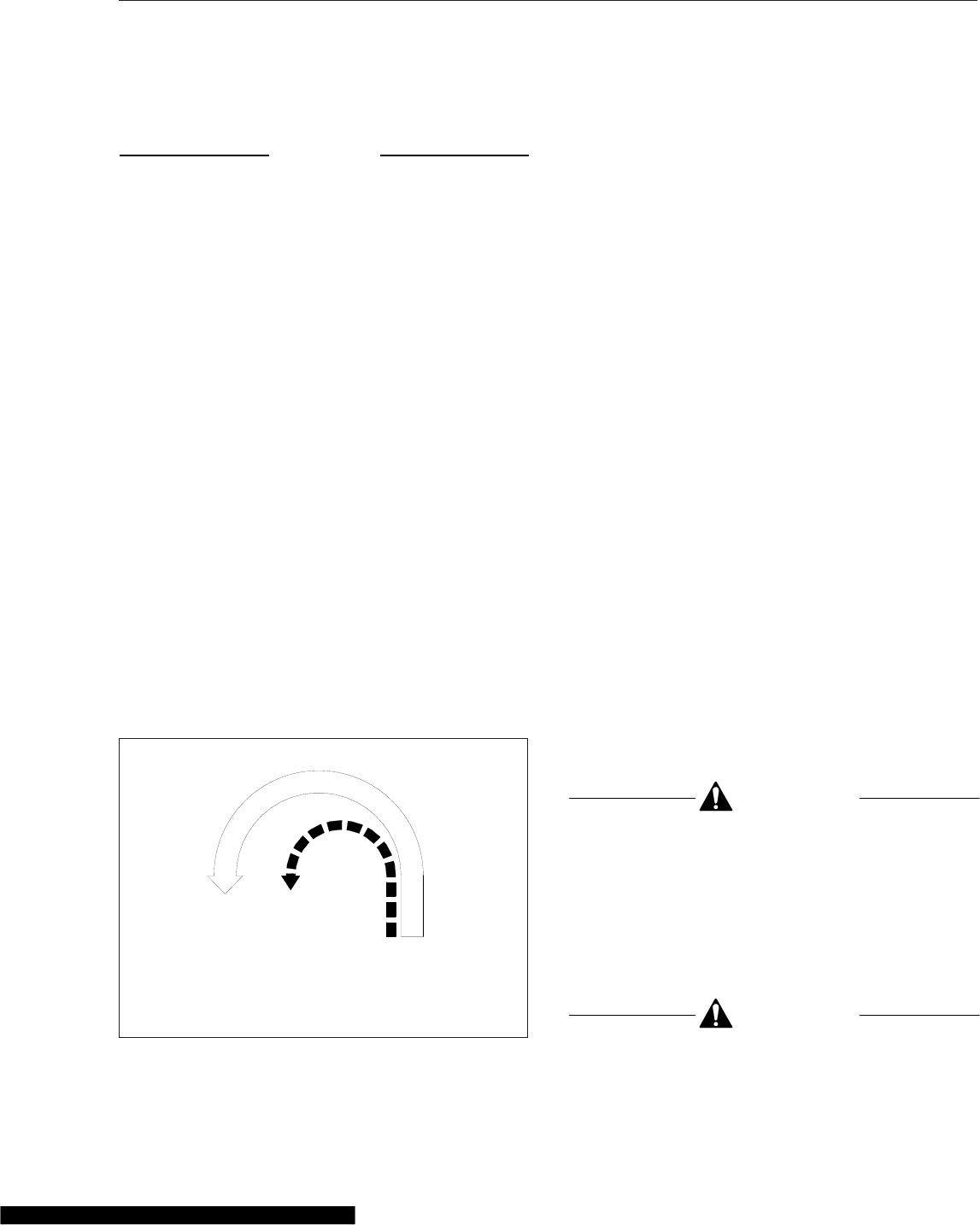
Main Differential Lock Operation
NOTICE
The differential lock should be engaged when the
vehicle is stopped or moving at a low, constant
speed and the wheels are not spinning, slipping,
or losing traction. Engagement at high speed or
power can damage the axle(s).
Do not permit rear wheels to spin freely for more
than ten seconds when traction is lost. Shift into
LOCK to prevent damage to interaxle and main
differentials.
To lock the main differential and obtain maximum
traction under slippery conditions, move the control
switch to the lock position.
NOTE: On some vehicles, the differential lock
system is connected through the low speed
range of the transmission. If this system is used,
the transmission must be in the low speed
range for the differential to fully lock.
If the vehicle is moving, maintain a constant vehicle
speed while engaging the differential lock. Briefly let
up on the accelerator to relieve torque on the gear-
ing, allowing the differential to fully lock. The indica-
tor light should come on and the buzzer should
sound on vehicles so equipped. When the differential
is fully locked, the turning radius will increase be-
cause the vehicle understeers. See Fig. 16.1. Drive
cautiously and do not exceed 25 mph (40 km/h).
To unlock the main differential, move the control
switch to the unlock position. Briefly let up on the
accelerator to relieve torque on the gearing, allowing
the differential to fully unlock.
NOTE: If the differential lock system is con-
nected through the low speed range of the
transmission, shifting out of low speed range will
also unlock the differential.
When the differential lock disengages, the indicator
light will go off and the buzzer will stop.
Single Drive Axles with Traction
Equalizer
Some single drive axles are equipped with a traction
equalizer that is a load-sensing, self-actuating fea-
ture. A traction equalizer provides normal differential
action where traction is good. When one wheel be-
gins to spin faster than the other, clutch plates in the
differential housing automatically engage, delivering
power to both wheels. There is no operator control
with this feature.
A traction equalizer occasionally tends to slip in a
jerking motion, producing irregular intervals of sharp
noises. This generally occurs when the vehicle is op-
erating at low speeds on fairly sharp turns. This con-
dition is corrected by adding a friction modifier to the
axle lubricant. This additive tends to reduce the static
coefficient of friction to a value equal to, or lower
than, the sliding coefficient.
See Group 35 of the Cascadia™Maintenance
Manual for additional information on friction modifiers
and when to add them to axle lubricants.
CAUTION
Tire sizes on both rear wheels should be the
same on axles equipped with a traction equalizer.
If not, excessive wear may occur in the traction
equalizer.
Two-Speed Drive Axles
Axle Shift
CAUTION
To prevent transmission and axle damage, make
sure the automatic transmission is in high range
02/09/96 f350079a
A
B
A. Turning Radius When Differential is Locked
(engaged)—Understeer Condition
B. Turning Radius When Differential is Unlocked
(disengaged)
Fig. 16.1, Turning Radius
Drive Axles
16.2
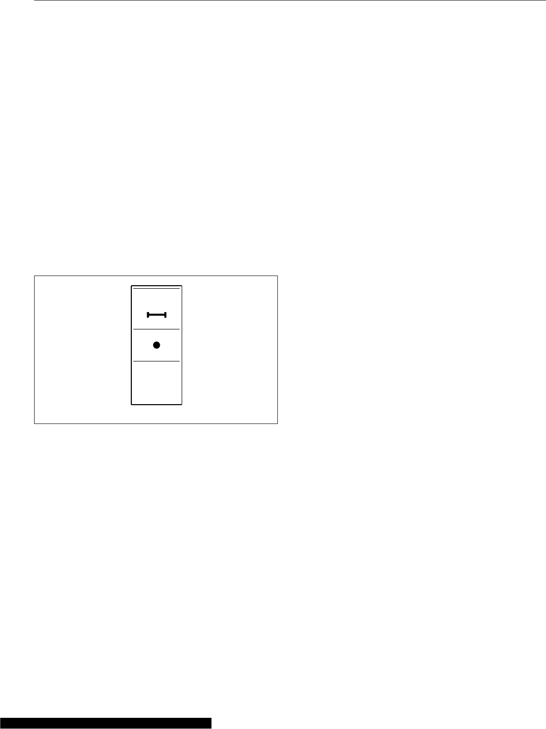
when performing an axle shift with the vehicle
moving.
Axle shift is a function installed on vehicles with two-
speed axles to allow the use of the low speed range
when greater traction and maximum pulling power is
needed at low engine speed (rpm).
Under normal operating conditions, the vehicle is op-
erated using the high-speed gear ratios of the axle.
Under extreme weather or off-road conditions, at low
speed and rpm and/or to pull heavy loads, the ve-
hicle must be operated using the low-speed, or re-
duction, gear ratios of the axle.
Axle Shift Switch
The axle shift switch is a two-position rocker switch
(Fig. 16.2) installed on vehicles with two-speed
axles.
To shift the axle from low speed to high speed, press
the top of the switch. To turn the axle shift off (switch
from high speed back to low speed), press the bot-
tom of the switch. When the axle has shifted speed,
the LED turns off.
When the panel lights are on, the AXLE SHIFT leg-
end is backlit in green.
IMPORTANT: If the LED in the switch begins to
blink during normal operation, when the switch
has not been activated, this indicates an error
condition. Bring the vehicle to an authorized
Freightliner service facility as soon as possible.
When the axle shift switch is pressed, three re-
sponses are possible: a normal response, a slow re-
sponse, and an abnormal response.
Normal Response: The LED in the switch blinks until
the axle shifts speed. At this point, the LED comes
on steady and stays illuminated. In normal operation,
the axle may shift so quickly that the blinking of the
switch is barely noticeable.
If operation of the switch is not possible for any rea-
son (interaxle lock is on, ignition is turned off, etc.),
the LED will stop blinking and turn off.
Slow Response: If operation of the switch is slowed
for any reason (by cold weather, low air pressure,
etc.), the switch will continue to blink until the axle
shifts. As in the normal response, the LED comes on
steady and stays illuminated.
Abnormal Response: If the LED blinks for more than
30 seconds, the axle shift function/mechanism may
not be operating correctly. Bring the vehicle to an
authorized Freightliner service facility for testing.
Axle Switch Interlock
NOTE: On vehicles with tandem drive axles,
there is an interlock that prevents an axle from
shifting speed whenever the interaxle lock is on.
If the axle shift switch is pressed when the interaxle
lock is on, the axle shift will not be completed. The
LED does the following:
•If the LED is off, the LED comes on briefly and
turns off again.
•If the LED is on, it stays on.
To complete the axle shift, turn off the interaxle lock
and press the axle shift switch again. If still needed,
the interaxle lock can then be reactivated.
AXLE
SHIFT
f61095106/12/2007
Fig. 16.2, Axle Shift Switch
Drive Axles
16.3

17
Steering System
Power Steering System General Information .......................................... 17.1
Power Steering Systems .......................................................... 17.1
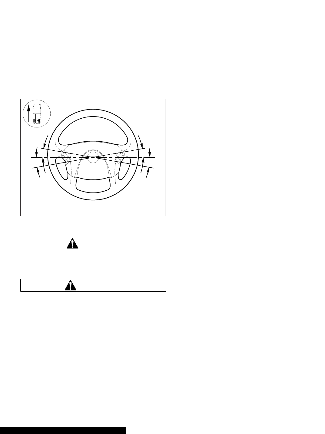
Power Steering System
General Information
When there is no load on the vehicle, and the front
tires are pointed straight ahead, the steering wheel
spokes should be centered, ±10 degrees, as shown
in Fig. 17.1. See Group 46 of the Cascadia™Work-
shop Manual for steering adjustment procedures.
CAUTION
Never steam clean or high-pressure wash the
steering gear. Internal damage to gear seals, and
ultimately the steering gear, can result.
WARNING
Driving the vehicle without the power-assist fea-
ture of the steering system requires much greater
effort, especially in sharp turns or at low speeds,
which could result in an accident and possible
injury.
Drivers should carefully use the power available with
a power steering system. If the front tires become
lodged in a deep chuckhole or rut, drive the vehicle
out, instead of using the steering system to lift the
tires from the hole. Also, avoid turning the tires when
they are against a curb, as this places a heavy load
on steering components and could damage them.
Power Steering Systems
Steering Gear System
The steering gear system includes the power steer-
ing gear, hydraulic hoses, power steering pump, res-
ervoir, and other components. Some models are also
equipped with a separate hydraulic power cylinder on
the right side of the front axle, or a right-hand slave
gear (such as the TRW RCH-45). The power steering
pump, driven by the engine, provides the power as-
sist for the steering system. If the engine is not run-
ning, there is no power assist. If the power-assist
feature does not work due to hydraulic fluid loss,
steering pump damage, or some other cause, bring
the vehicle to a safe stop. Do not drive the vehicle
until the cause of the problem has been corrected.
Rack and Pinion Steering System
The rack and pinion steering gear is mounted to the
front axle with two brackets, and connected by tie-
rod ends to the axle steering arms. When the steer-
ing wheel is turned, the intermediate steering shaft
turns the input shaft, rotating the torsion bar and the
valve. When the valve turns, power steering fluid is
redirected and provides power assist to turn the pin-
ion gear meshed with the rack teeth, moving the rack
left or right. The rack, with a tie-rod at each end,
then moves the steering arms on the axle, and pivots
the wheels.
This design provides drivers with more responsive
steering, with increased performance and “road feel.”
It virtually eliminates steering issues when the driver
hits a bump (bumpsteer), and significantly reduces
roll steer when a vehicle goes into a curve. Wander-
ing is significantly reduced as well, so the vehicle
tends to drive straight on the highway. It has a lower
steering ratio, which means drivers don’t have to turn
the steering wheel as much to get the wheels to turn
a given distance. Overall, rack and pinion steering
greatly improves steering response, and reduces
driver effort and fatigue.
06/13/2007 f462080
10°
10°
12
10°
10°
1. 9 o’Clock 2. 3 o’Clock
Fig. 17.1, Proper Steering Wheel Position (with tires
pointed straight ahead)
Steering System
17.1

18
Fifth Wheels
Fifth Wheels, General Information ................................................... 18.1
Fifth Wheel Coupling ............................................................. 18.1
Fifth Wheel Uncoupling ........................................................... 18.4
Fifth Wheel Slide ................................................................ 18.7
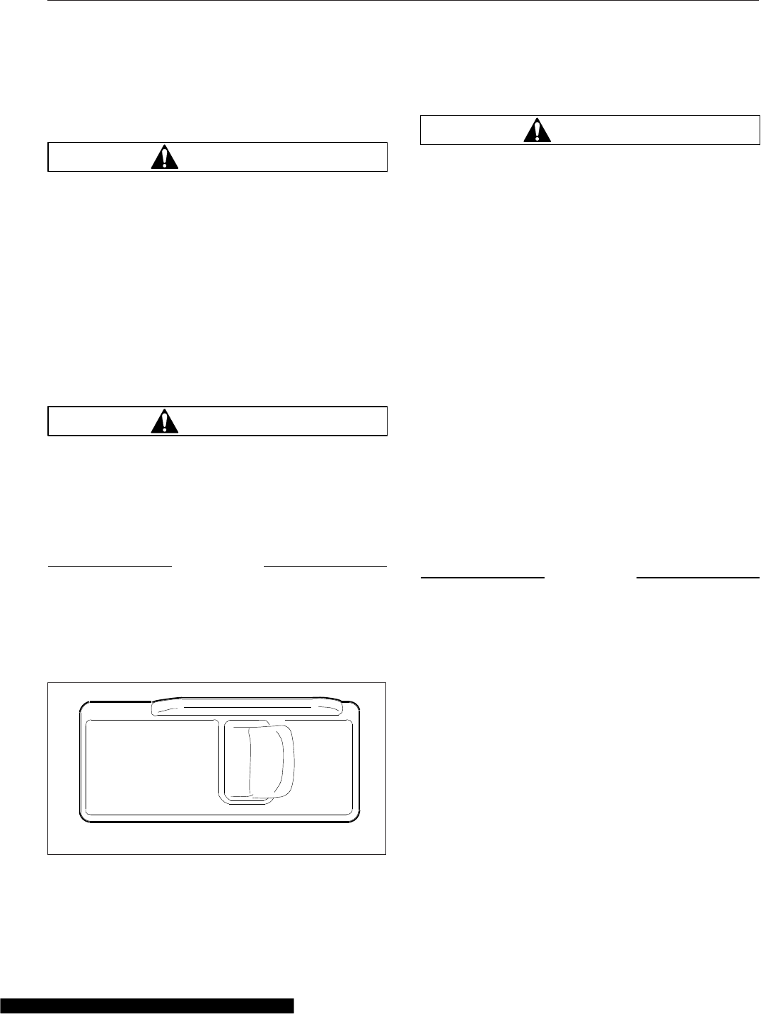
Fifth Wheels, General
Information
WARNING
Do not use any fifth wheel that fails to operate
properly. Doing so may cause loss of vehicle
control, possibly resulting in severe personal in-
jury or death.
Air-Suspension Dump Valve
The air-suspension dump valve may be used to ad-
just the tractor height to aid with coupling to or un-
coupling from a trailer. See Fig. 18.1. When the
switch is set to LOWER, the air-suspension dump
valve deflates the air springs to lower the rear of the
vehicle. In the AUTO position, the automatic ride-
control valves operate for normal driving.
WARNING
Never exhaust air from the suspension while
driving. The suspension will not absorb road
shocks, possibly damaging components, and ve-
hicle handling may be compromised. This could
result in loss of vehicle control, possibly result-
ing in severe personal injury or death.
NOTICE
Do not operate the vehicle over uneven ground
such as ramps, speed bumps, curbs, etc. with
the air springs deflated. Doing this may lead to
air bag separation from the piston, preventing the
suspension air springs from inflating.
Fifth Wheel Lubrication
WARNING
Keep the fifth wheel plate lubricated to prevent
binding between the tractor and trailer. A binding
fifth wheel could cause erratic steering and loss
of vehicle control, possibly resulting in personal
injury or death.
The standard fifth wheel plate must be kept well lu-
bricated with chassis grease to prevent friction and
binding between the tractor fifth wheel plate and the
trailer.
For a low-lube fifth wheel plate, inspect the condition
of the low-lube pads. There should be no damaged
or missing pieces. Slight puckering at the outside
edges is normal.
For lubrication instructions, see Group 31 of the
Cascadia® Maintenance Manual.
Fifth Wheel Coupling
Fifth wheel coupling is activated with the lock control
handle located on either the right side or left side of
the fifth wheel. Coupling has successfully occurred
when the kingpin has been forced into the jaws and
the lock control handle has moved to the locked
position.
NOTICE
Some fifth wheels may be mounted on sliding
rails. Before attempting to couple a trailer to a
sliding fifth wheel, the slide feature must be
locked to prevent the top plate from sliding rap-
idly forward or rearward, causing damage to the
fifth wheel or kingpin.
Fontaine and Holland Fifth Wheels
Coupling
1. Chock the front and rear of the trailer tires to
prevent the trailer from moving.
2. Ensure the fifth wheel jaw is fully open and the
operating rod is in the unlocked position. See
Fig. 18.2 or Fig. 18.3.
3. Make sure the fifth wheel top plate is tilted so the
ramps are as low as possible.
10/25/2010 f611101
DO NOT LOWER
WHEN VEHICLE
IS IN MOTION
LOWER AUTO
SUSP
AIR
Fig. 18.1, Air-Suspension Dump Valve
Fifth Wheels
18.1
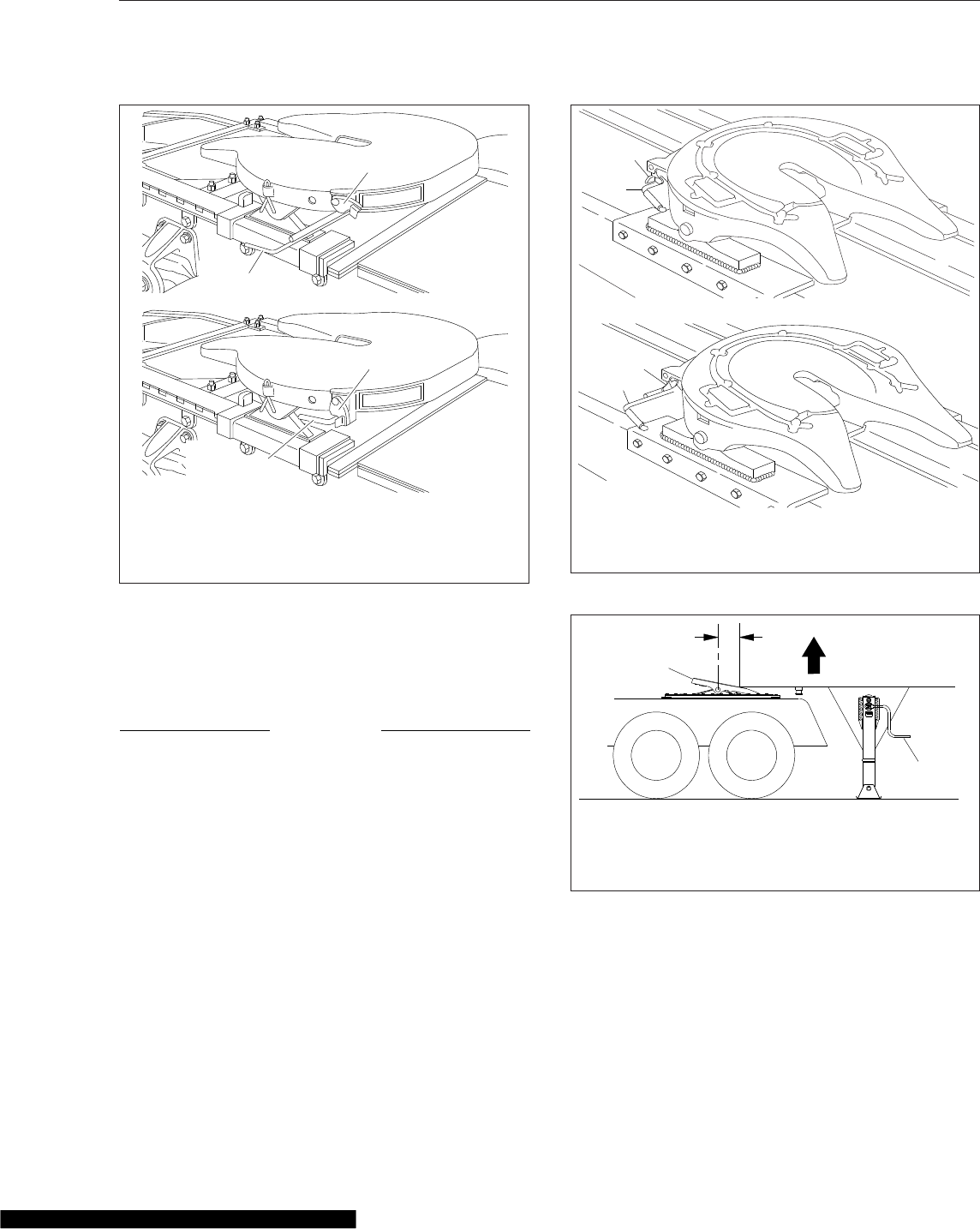
4. Position the tractor so that the center of the fifth
wheel is in line with the trailer kingpin. The king-
pin should be in a position to enter the throat of
the locking mechanism.
NOTICE
Attempting to couple at the wrong height may
cause improper coupling, which could result in
damage to the fifth wheel or kingpin.
5. Adjust the trailer height if required.
For a standard fifth wheel plate, the trailer
should contact the fifth wheel approximately 4 to
8 inches (10 to 20 cm) behind the fifth wheel
pivot. See Fig. 18.4.
For a low-lube fifth wheel plate, the fifth wheel
must slide freely under the trailer, and the trailer
should contact the fifth wheel at the pivot. See
Fig. 18.5.
6. With the fifth wheel lock opening aligned with the
trailer kingpin, back the tractor slowly toward the
trailer. After sliding under the trailer, STOP to
prevent from hitting the kingpin too hard, then
resume backing slowly until the fifth wheel locks.
On a standard fifth wheel, the fifth wheel must lift
the trailer.
On a low-lube fifth wheel, do not lift the trailer as
this may damage the fifth wheel plate.
1
1
2
2
10/26/2010 f310110a
A
B
NOTE: Make sure the safety latch is down when the
control handle is locked.
A. Unlocked B. Locked
1. Safety Latch 2. Lock Control Handle
Fig. 18.2, Fontaine Locking Mechanism
1
1
2
3
11/02/2010 f310447
1. Safety Latch
2. Operating Rod (locked)
3. Operating Rod (unlocked)
Fig. 18.3, Holland Simplex SE Locking Mechanism
10/28/2010 f311124
A
B
C
D
A. Fifth wheel must lift
trailer
B. Adjust trailer height
C. Ramps tilted down
D. 4 to 8 inches
Fig. 18.4, Trailer Connection Point, Standard Fifth
Wheel
Fifth Wheels
18.2
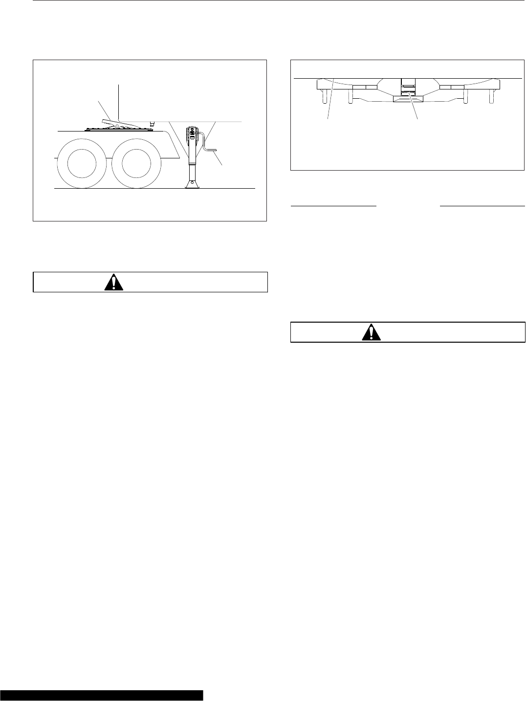
7. Apply the tractor parking brakes.
WARNING
A visual inspection is required by law. Some im-
proper couplings can pass a pull test. Sound is
not reliable. Get out of the cab and look. Incor-
rect coupling could cause the trailer to discon-
nect, possibly resulting in serious personal injury
or death.
8. Perform a coupling inspection, checking that
there is no gap between the bottom of the trailer
and the fifth wheel, and that the kingpin is se-
curely locked. See Fig. 18.6
When lockup has occurred, the fifth wheel con-
trol handle moves to the locked position. Make
sure that the safety latch is down over the lock
control handle to hold the control handle in the
locked position. (The safety latch will only rotate
down if the operating rod is fully retracted in the
locked position.) See Fig. 18.2 for Fontaine fifth
wheels. See Fig. 18.3 for Holland fifth wheels.
9. Release the tractor parking brakes. Test for king-
pin lockup slowly inching the tractor forward, pull-
ing on the trailer against the chocks.
10. After lockup is completed, connect the tractor-to-
trailer air system lines and the electrical cable to
the trailer. Take care to prevent dirt or foreign
material from entering the air system lines.
NOTICE
Always make sure the connection hanger keeps
the trailer air hoses and electrical cables posi-
tioned so that they do not rub on anything. Rub-
bing may wear through hoses or cables, resulting
in air leaks, or exposed or broken wires, poten-
tially affecting trailer brake or electrical systems.
11. Charge the air brake system with air, checking
that the air connections do not leak.
WARNING
Incorrect fifth wheel lock adjustment could cause
the trailer to disconnect, possibly resulting in se-
rious personal injury or death.
12. With the trailer wheels chocked and the brakes
set, check for clearance between the kingpin and
the fifth wheel jaws by moving the tractor forward
and backward against the locked kingpin. If slack
is present, uncouple the trailer and have the fifth
wheel inspected and adjusted by a certified
technician.
Jost Fifth Wheel Coupling
1. Tilt the ramp down.
2. Open the kingpin locks. See Fig. 18.7.
3. Back the vehicle close to the trailer, centering the
kingpin on the fifth wheel.
4. Chock the trailer wheels.
5. Connect the air lines and electrical cable.
6. Ensure that the red trailer air supply valve (trailer
brake) is pulled out, and that the trailer parking
09/10/2010 f311125
A
B
A. Adjust trailer height B. Ramps tilted down
Fig. 18.5, Trailer Connection Point, Low-Lube Fifth
Wheel
09/10/2010 f311126
AB
A. No gap between trailer
and fifth wheel
B. Kingpin inside lock
Fig. 18.6, Coupling Inspection
Fifth Wheels
18.3
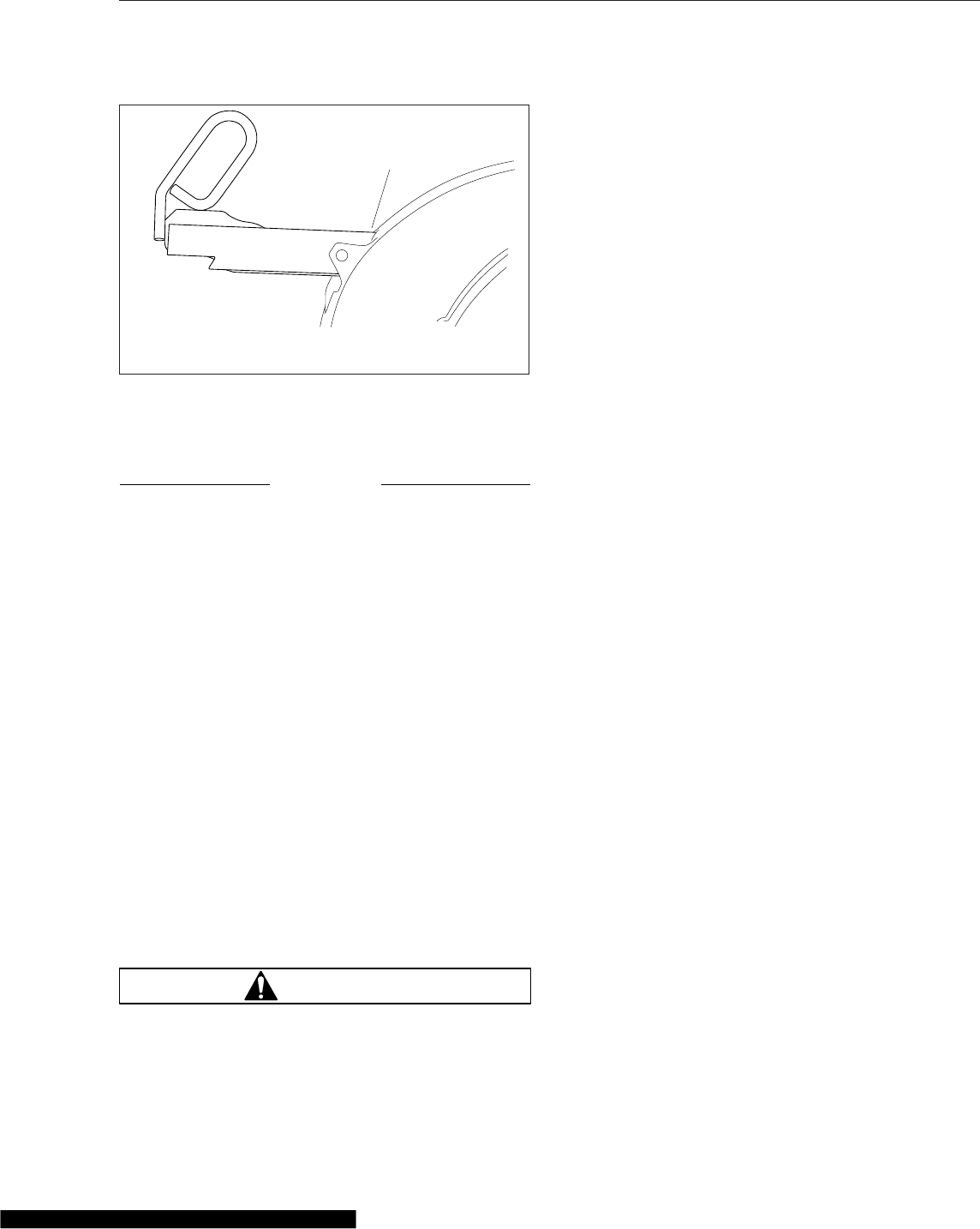
brakes are set. See Chapter 5 in this manual for
operation of the dash-mounted brake controls.
NOTICE
Attempting to couple at the wrong height may
cause improper coupling, which could result in
damage to the fifth wheel or kingpin.
7. Adjust the trailer height (if required).
For a standard fifth wheel plate, the trailer
should contact the fifth wheel approximately 4 to
8 inches (10 to 20 cm) behind the pivot. See
Fig. 18.4.
For a low-lube fifth wheel plate, the fifth wheel
must slide freely under the trailer, and the trailer
should contact the fifth wheel at the pivot. See
Fig. 18.5.
8. Back the tractor under the trailer.
On a standard fifth wheel, the fifth wheel must lift
the trailer.
On a low-lube fifth wheel, do not lift the trailer as
this may damage the fifth wheel plate.
9. After sliding under the trailer, STOP to prevent
from hitting the kingpin too hard, then resume
backing slowly until the fifth wheel locks.
WARNING
A visual inspection is required by law. Some im-
proper couplings can pass a pull test. Sound is
not reliable. Get out of the cab and look. Incor-
rect coupling could cause the trailer to discon-
nect, possibly resulting in serious personal injury
or death.
10. Apply the tractor parking brake, then perform a
physical check for positive kingpin lockup, and
that there is no gap between the trailer and the
fifth wheel. See Fig. 18.6.
11. Ensure that the release handle is in the locked
position adjacent to the casting. See Fig. 18.8.
12. Release the tractor parking brakes and test for
kingpin lockup by slowly moving the tractor for-
ward, pulling on the trailer against the chocks.
Fifth Wheel Uncoupling
Manual Uncoupling
1. Apply the tractor and trailer parking brakes.
2. Chock the trailer rear wheels.
3. Lower the trailer landing gear until the weight is
removed from the fifth wheel.
4. Disconnect the tractor-to-trailer air system lines
and electrical cable. Plug the air lines to prevent
dirt or foreign material from entering the lines.
5. Verify that both the yellow parking-brake and red
trailer-air-supply knobs are out, the tractor and
trailer parking brakes are set, and that the trailer
is prepared for uncoupling.
6. Release the kingpin locking mechanism following
the instructions for each manufacturer below.
6.1 Fontaine: Lift the safety latch and pull the
lock control handle to the unlocked posi-
tion. See Fig. 18.2.
6.2 Holland: In the locked position the safety
indicator swings freely over the operating
rod. See Fig. 18.9, View A.
To unlock the mechanism, manually rotate
the safety indicator toward the rear of the
fifth wheel. See Fig. 18.9, View B.
Pull the operating rod out. When the
upper operating rod shoulder is outside
the slot, raise the handle and place the
shoulder of the upper rod against the plate
casting, above the slot. See Fig. 18.9,
View C.
09/10/2010 f311128
A
A. Lock held open by catch mechanism
Fig. 18.7, Jost Release Handle Unlocked
Fifth Wheels
18.4
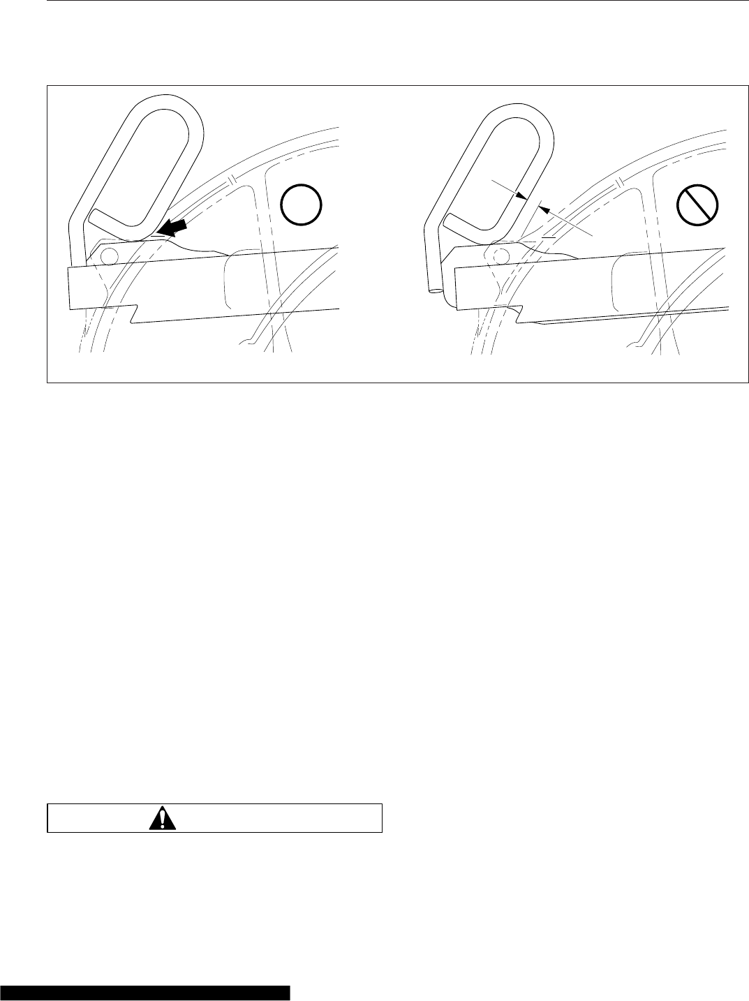
The fifth wheel is now in the lockset posi-
tion and is ready for uncoupling. As the
tractor pulls away from the trailer the king-
pin forces the jaw to rotate, contacting the
lock. Continued rotation of the jaw forces
the lock to move outward, and drops the
upper rod back into the slot. See Fig. 18.9
View D. The wheel is now ready for
coupling.
6.3 Jost: Pull the retractable handle out, then
secure it in the open position with the
catch. See Fig. 18.7.
7. Release the tractor parking brake then drive out
slowly, allowing the trailer to slide down the fifth
wheel and pick-up ramps.
Air-Actuated Uncoupling
An air-actuated kingpin release valve is optional with
all fifth wheels. See Fig. 18.10.
NOTE: In the event of an air system failure, air-
actuated kingpins can be manually released fol-
lowing the instructions for manual unlocking.
WARNING
Once the kingpin release valve has been pulled
the kingpin lock is released. The vehicle MUST
NOT be driven with the trailer until the trailer has
been uncoupled and coupled again. Failure to do
so may result in separation of the trailer from the
tractor, possibly causing serious personal injury
or death.
Preparing the Trailer for Uncoupling
Before using the air valve to unlock a fifth wheel
kingpin, prepare the trailer as follows.
1. Apply the tractor and trailer parking brakes.
2. Chock the trailer rear wheels.
3. Lower the trailer landing gear until the weight is
removed from the fifth wheel.
4. Disconnect the tractor-to-trailer air lines and elec-
trical cable. Plug the air lines to prevent dirt or
foreign material from entering the lines.
Fontaine and Holland Fifth Wheels Air-
Activated Kingpin Unlock
1. Verify that both the yellow parking-brake and red
trailer-air supply knobs are out, the tractor and
trailer parking brakes are set, and that the trailer
is prepared for uncoupling.
NOTE: On Fontaine and Holland fifth wheels, if
the tractor parking brake is not set, the air-
actuated kingpin-release valve will not activate.
09/10/2010 f311127
OK OK
Fig. 18.8, Jost Release Handle Locked
Fifth Wheels
18.5
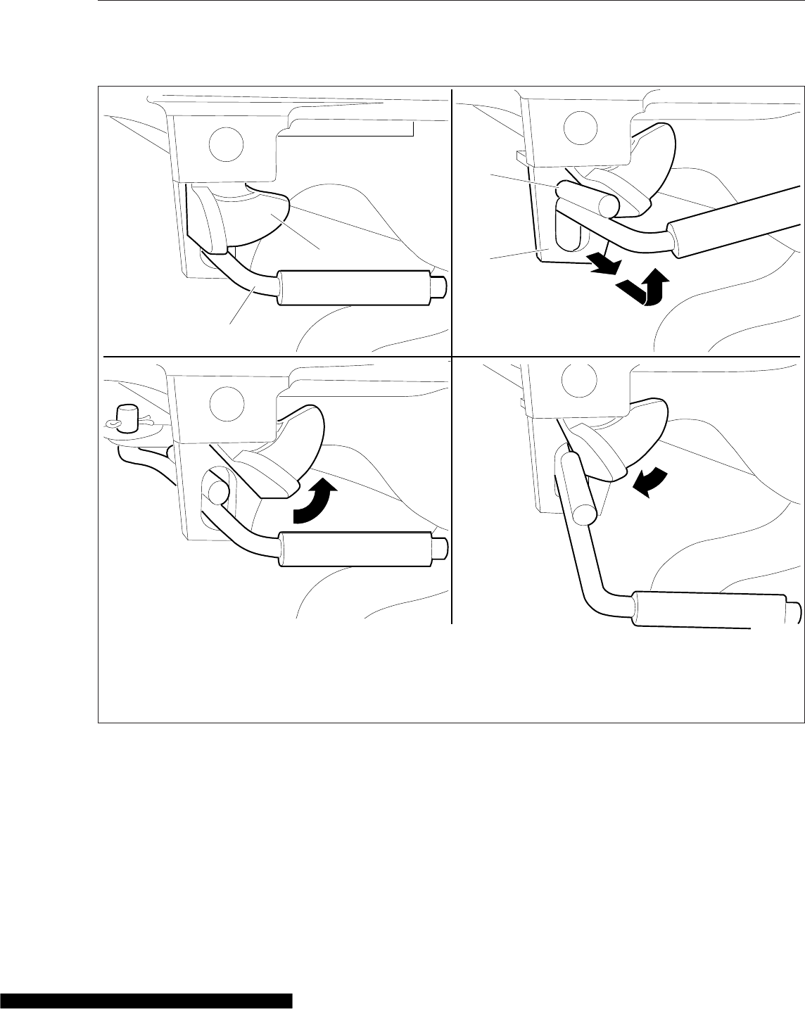
2. Pull and hold the kingpin release valve
(Fig. 18.10) until the kingpin lock mechanism
opens and locks in place.
3. Release the pull valve.
4. Release the tractor parking brake.
5. Drive out from under the trailer.
Jost Fifth Wheels Air-Activated Kingpin
Unlock
1. Verify that both the yellow parking-brake and red
trailer-air-supply knobs are out, the tractor and
trailer parking brakes are set, and that the trailer
is prepared for uncoupling.
11/02/2010 f311133
A
B
C
D
1
2
3
4
A. Locked Position
B. Unlatched Position (safety indicator rotated towards the
rear of the fifth wheel)
C. Lockset Position (upper rod resting against casting
above slot)
D. Open Position (ready for recoupling)
1. Safety Indicator
2. Operating Rod
3. Upper Rod
4. Plate Casting
Fig. 18.9, Holland Kingpin Locking Mechanism
Fifth Wheels
18.6
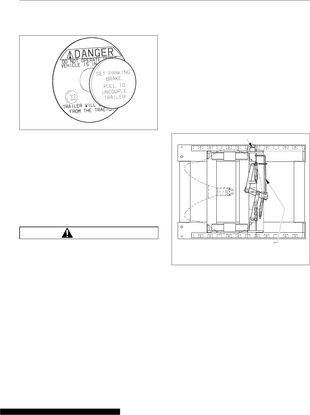
NOTE: With Jost fifth wheels, if the trailer park-
ing brake is not set the air-actuated valve will
not activate.
2. Release the tractor parking brake.
3. Pull and hold the kingpin release valve, then
drive forward slowly.
4. After the trailer has slid down the fifth wheel and
pick-up ramps, release the pull valve.
Fifth Wheel Slide
WARNING
Adjust the fifth wheel slide correctly, and do not
overload any tractor axle by incorrectly loading
the trailer. Incorrect slide adjustment or improper
axle loading could cause erratic steering and
loss of vehicle control, possibly resulting in seri-
ous personal injury or death.
On sliding fifth wheel assemblies, the fifth-wheel
plate is attached to rails that allow forward and rear-
ward movement of the fifth wheel to optimally distrib-
ute the load across the axles. Slots are evenly
spaced along the slide rails, and retractable wedges
are positioned through the slots to hold the fifth
wheel in the desired position.
The amount of load distribution on the front steering
axle and rear drive axle(s) will have a direct effect on
the steering control of the vehicle. Determine the
front and rear axle weights by weighing the vehicle
on scales designed for this purpose.
The maximum axle weight ratings are shown on the
Federal Motor Vehicle Safety Standard (FMVSS)
label or Canadian Motor Vehicle Safety Standard
(CMVSS) label attached to the left rear door post of
the tractor. The desired load on the axle is no less
than 80 percent of the maximum axle weight rating,
but in no instances should the axle load exceed the
maximum axle weight rating given on the FMVSS or
CMVSS label.
Manual Slide Operation
The manual slide feature is operated from the fifth
wheel plate with a manual release handle using the
following procedure. See Fig. 18.11.
1. Stop the tractor and trailer in a straight line on
level ground. Pull the red trailer air supply knob
to apply the trailer parking brakes.
2. Apply the tractor parking brake, then release the
sliding mechanism using the appropriate method
for the fifth wheel manufacturer.
2.1 Fontaine: Lift the slide release pull handle
to disengage it from the guide plate. Then,
pull out the handle until it is in the un-
locked position and can be positioned
against the guide plate to hold it out. The
10/26/2010 f611102
Fig. 18.10, Air-Actuated Kingpin Release Valve
07/25/95 f310190
1
2
1. Locking Wedge
2. Slide Release Pull Handle
Fig. 18.11, Manual Release Sliding Fifth Wheel
(Fontaine shown)
Fifth Wheels
18.7
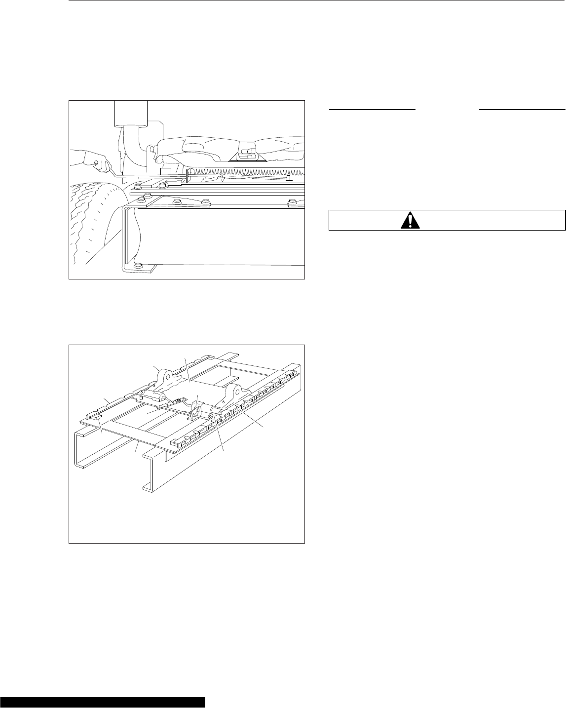
handle will stay in the unlocked position
until it is manually disengaged from the
guide plate. See Fig. 18.12.
2.2 Holland: Pull the operating rod out. Make
sure both side plungers have released.
See Fig. 18.13.
3. Lower the trailer landing gear just enough to re-
move the weight from the tractor.
4. Chock the front and rear of the trailer tires to
prevent the trailer from moving.
5. Release the tractor parking brakes, then slowly
move the tractor forward or backward until the
fifth wheel is in the desired location.
NOTICE
When moving the fifth wheel to the desired posi-
tion, be sure the trailer landing gear will not at
any time come in contact with the tractor frame
or other components. Make sure that the front of
the trailer will not come in contact with the rear
of the cab or with other components if they ex-
tend beyond the rear of the cab.
WARNING
Check that the locking wedges have seated in the
slots. Failure to achieve complete lockup may
allow disengagement of the tractor from the
trailer, possibly resulting in serious personal in-
jury or death.
6. Apply the tractor parking brakes, then lock the
sliding member in position using one of the fol-
lowing methods:
6.1 Fontaine: Disengage the slide release
pull handle from the guide plate. The slide
release pull handle is spring-loaded in the
locked position and will seek the locked
position when disengaged from the guide
plate. After the slide release pull handle
returns to the fully locked position, visually
and physically check the locking wedges
to make sure they are fully inserted into
the slots in the slide rails. Make sure the
handle is locked in position against the
guide plate.
6.2 Holland: Raise the operating rod so that it
is free to move inward. Make sure that the
lock pins have seated in the base plate
rail holes and the operating rod moves
into the locked position.
NOTE: The fifth wheel may need to be moved
slightly to enable the locking wedges to enter
the fully locked position.
10/26/2010 f310050
Fig. 18.12, Releasing the Sliding Fifth Wheel, (Fontaine)
1
2
3
4
5
6
3
10/26/2010 f310445
7
8
1. Baseplate
2. Bolted Stop
3. Baseplate Rail
4. Fifth Wheel Mount
5. Slider Saddle Plate
6. Safety Latch
7. Operating Rod
8. Operating Lever
Fig. 18.13, Sliding Fifth Wheel Manual Release,
(Holland Simplex)
Fifth Wheels
18.8
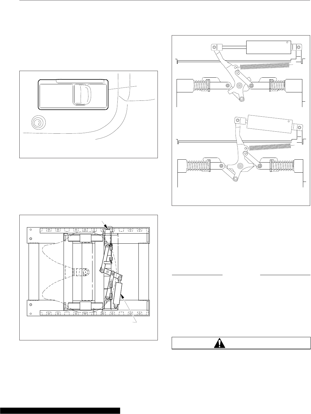
Air Slide Operation
The slide feature may be operated with an air switch
mounted in the dash, that operates an air cylinder
that locks and unlocks the slide. See Fig. 18.14.
1. Set the air-slide switch (Fig. 18.14) to UNLOCK.
Ensure the locking plungers have released. See
Fig. 18.15.
For Jost fifth wheels, the mechanism activates as
shown in Fig. 18.16.
2. Lower the trailer landing gear just enough to re-
move the weight from the tractor.
3. Pull the red trailer-air-supply knob to set the
trailer-parking brakes.
4. Slowly move the tractor forward or backward
until the fifth wheel is in the desired location.
NOTICE
Ensure the trailer landing gear does not come in
contact with the tractor frame or other compo-
nents, and that the front of the trailer will not
come in contact with the rear of the cab or other
components if they extend beyond the rear of the
cab.
5. Apply the tractor parking brakes.
WARNING
Check that the locking wedges have seated in the
slots. Failure to achieve complete lockup may
LOCKUNLOCK
FIFTH
WHL
SLIDE
MUST BE
LOCKED WHEN
VEHICLE IS IN
MOTION
10/22/2009 f611074
1
1. Fifth Wheel Air-Slide Switch
Fig. 18.14, Air-Slide Switch
07/25/95 f310189
1
2
1. Locking Wedge 2. Air Cylinder
Fig. 18.15, Air-Operated Sliding Fifth Wheel (Fontaine
shown)
09/10/2010 f311131
A
B
A. Unlocked B. Locked
Fig. 18.16, Jost Sliding Fifth Wheel
Fifth Wheels
18.9

allow disengagement of the tractor from the
trailer, possibly resulting in serious personal in-
jury or death.
6. Set the air-slide switch to LOCK. Visually inspect
the locking wedges or plungers to make sure
that they are fully inserted in the slide rail slots.
Verify that the plungers have engaged by tugging
the tractor forward while the trailer brakes are
locked and the wheels are chocked.
NOTE: The fifth wheel may need to be moved
slightly to enable the locking wedges to fully
lock.
Fifth Wheels
18.10

19
Trailer Couplings
Air-Suspension Dump Valve ....................................................... 19.1
Holland Trailer Coupling ........................................................... 19.1
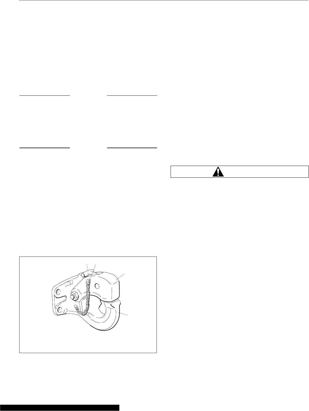
Air-Suspension Dump Valve
The air-suspension height switch may be used to aid
in connecting or disconnecting from a trailer. When
the switch is set to LOWER, the air-suspension
dump valve deflates the air springs to lower the rear
of the vehicle. In the AUTO position, the automatic
ride-control valves operate for normal driving.
NOTICE
Do not operate the vehicle over uneven ground
such as ramps, speed bumps, curbs, etc. with
the air springs deflated. Doing this may lead to
air bag separation from the piston, preventing the
suspension air springs from reinflating.
NOTICE
Never exhaust air from the suspension while
driving. When the air is exhausted, the suspen-
sion will not absorb road shocks, and compo-
nents may be damaged.
Holland Trailer Coupling
General Information
The Holland PH-T-60-AL trailer coupling is designed
for use with trailers having a maximum gross weight
of 10,000 lb. See Fig. 19.1. It is a rigid-type pintle
hook, used only on tractor applications, and is fas-
tened to the rear closing crossmember of the vehicle.
It is a non-air-adjusted coupling.
Operation
Trailer Hookup
1. Chock the front and rear tires of the trailer.
2. Remove the cotter pin, then lift the lock and raise
the latch.
3. Back up the vehicle, until the drawbar eye is
over the pintle hook.
4. Lower the trailer, until the drawbar eye rests on
the pintle hook.
5. Close the latch, then insert the cotter pin.
6. Hook up the trailer electrical and air lines.
7. Remove the chocks from the trailer’s tires.
Trailer Release
1. Apply the tractor and trailer parking brakes.
WARNING
Do not use the trailer air supply for parking trail-
ers not equipped with spring parking brakes.
This applies the trailer service brakes only. As air
bleeds from the trailer brake system, brake appli-
cation is lost. This could allow the unattended
vehicle to roll away, possibly resulting in serious
personal injury or death.
2. Chock the front and rear tires of the trailer.
3. Disconnect the trailer air and electrical lines.
Plug the air lines to keep out dirt.
4. Take the weight of the trailer drawbar off the
pintle hook.
5. Open the latch, by first removing the cotter pin,
then lift up the lock and raise the latch.
6. Slowly drive the vehicle away from the trailer.
12
3
4
01/20/95 f310314a
1. Lock
2. Cotter Pin
3. Latch
4. Pintle Hook
Fig. 19.1, Holland PH-T-60-AL Trailer Coupling
Trailer Couplings
19.1

20
Pre- and Post-Trip
Checklists
Periodic Inspections and Maintenance, General Information .............................. 20.1
Checklists ...................................................................... 20.1
Fluids Added .................................................................... 20.2

Periodic Inspections and
Maintenance, General
Information
Regulations in Canada and the U.S. clearly indicate
that it is the driver’s responsibility to perform an in-
spection, and ensure the complete road-worthiness
of a vehicle, before placing it into service. Commer-
cial vehicles may be subject to inspection by autho-
rized inspectors, and an unsafe vehicle can be taken
"out of service" until the driver or owner repairs it.
Use the following checklists to ensure that vehicle
components are in good working condition before
each trip. Careful inspections eliminate stops later to
fix overlooked or forgotten items.
The checklists in this chapter can be copied and kept
as a record that the procedures have been com-
pleted. For details on how to inspect each item on
the checklists, see the corresponding procedure
(step number) in Chapter 21.
Checklists
NOTE: Checklists in this chapter correspond
with the procedures and steps in Chapter 21,
Pre- and Post-Trip Inspections and Mainte-
nance. Your vehicle may not be equipped with
all components listed below.
Daily Pretrip Inspection Checklists
See the following tables for a list of procedures that
should be performed daily, before the first trip. Place
a check mark in the complete (Comp.) column to
indicate a procedure has been performed.
Inspector Date
Suspension and Slack Adjusters Comp.
1 Suspension components
2 Slack adjusters
Wheels and Tires Comp.
1 Wheel covers
2 Tire condition
3 Tire inflation
4 Rims and wheel components
Wheels and Tires Comp.
5 Wheel bearing oil seals and lubrication levels
6 Mud Flaps
Saddle Tank Areas Comp.
1Drain air reservoirs (without automatic drain
valves)
2 Fuel tank(s) secure
3 Frame rails and crossmembers
4 Visible exhaust components
Engine Compartment Comp.
1 Leakage under engine
2 Air intake system
3 Engine oil level
4 Power steering reservoir level
5 Engine coolant level
6 Visible engine wiring
7 Frame rails
Cab Comp.
1Reset dash-mounted air intake restriction
indicator
2 Air-pressure warning systems
3 Air governor cut-in and cut-out pressures
4 Air pressure build-up time
5 Air system leakage
6 Air pressure reserve
7 Mirrors, windows, windshield
8 Horn, windshield wipers, windshield washers
9 Heater and defroster
10 Interior lights
11 Exterior lights
12 Seat belts and tether belts
13 Fuel level
14 Mirror adjustment
15 Service brakes
16 Backup alarm
Natural Gas Fuel System Comp.
1 Fuel tanks
2 Required decals
3 Vent caps
4Plumbing components, fuel fill fitting, fuel
lines
5Fuel gauge components, fuel level sender
cable, LNG fuel tank pressure
6 Coolant hoses
7 LNG fuel tank pressure
Pre- and Post-Trip Checklists
20.1

Natural Gas Fuel System Comp.
8 LNG vaporizer
9 Low pressure filter drain
Weekly Post-trip Inspection Checklist
See the following table for procedures that should be
performed weekly, post-trip. Place a check mark in
the complete (Comp.) column to indicate a proce-
dure has been performed.
Inspector Date
Engine Compartment Comp.
1 Windshield washer reservoir level
2 Air intake restriction indicator
3 Water evacuation components
4 Automatic transmission fluid level
5 Water in fuel/water separator
6 Steering components
7 Serpentine drive belts
Monthly Post-trip Inspection
Checklists
See the following tables for procedures that should
be performed monthly, post-trip. Place a check mark
in the complete (Comp.) column to indicate a proce-
dure has been performed.
Inspector Date
Brake Components Comp.
1 Brake system components
2 Brake chambers
3 Air brake lines
4 Flex air hoses
5 Brake linings and brake drums
6 Brake lining thickness
Saddle Tank Areas Comp.
1Drain air reservoirs (with automatic drain
valves)
2 Batteries (location may vary)
3 Aerodynamic components
Engine Compartment Comp.
1 Hood and bumper
2 Hydraulic clutch reservoir
3 Radiator and heater hoses
4 Steering wheel play
Fluids Added
Use the following table to note any fluids that were
added during the inspection and maintenance proce-
dures.
Fluids Added During Inspection
Fluid Amount Added
Wheel Bearing Lubricant
Engine Oil
Power Steering Fluid
Engine Coolant
Windshield Washer Fluid
Automatic Transmission
Fluid
Hydraulic Clutch Fluid (DOT
4 brake fluid)
Pre- and Post-Trip Checklists
20.2

21
Pre- and Post-Trip
Inspections and
Maintenance
Daily Pretrip Inspection and Maintenance ............................................. 21.1
Weekly Post-Trip Inspections and Maintenance ....................................... 21.10
Monthly Post-Trip Inspections and Maintenance ...................................... 21.13
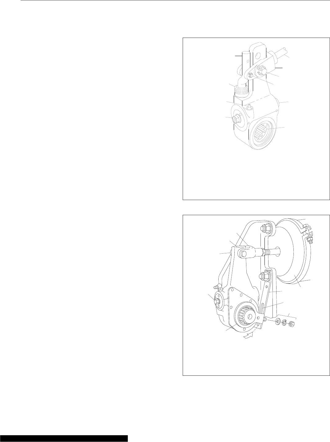
Daily Pretrip Inspection and
Maintenance
Complete the following inspection and maintenance
procedures to ensure that vehicle components are in
good working condition before each trip. A driver who
is familiar with the vehicle and drives it regularly can
perform the daily inspections, then add the weekly
and monthly post-trip inspections as scheduled.
If the driver does not operate the vehicle on a con-
sistent basis, all daily, weekly, and monthly inspec-
tion and maintenance procedures should be per-
formed before the trip.
IMPORTANT: The pre- and post-trip checklists,
inspections, and maintenance procedures de-
tailed in this chapter are not all-inclusive.
Refer to other component and body manufactur-
ers’ instructions for specific inspection and
maintenance instructions, as well as local, state,
and federal guidelines.
NOTE: If any system or component does not
pass this inspection, it must be corrected before
operating the vehicle. Whenever equipment re-
quires adjustment, replacement, and/or repair,
see the Cascadia Workshop Manual for proce-
dures and specifications.erticfied
Suspension and Slack Adjuster
Inspection
Walk around the vehicle and visually inspect suspen-
sion and slack adjuster components.
1. Inspect the following suspension components for
signs of structural damage, cracks, or wear.
•springs
•spring hangers
•shocks
•suspension arms
•suspension brackets
•axle seats
•bushings
2. Inspect slack adjusters for signs of damage. See
Fig. 21.1,Fig. 21.2,orFig. 21.3.
f421398
06/17/2003
1
2
3
45
6
7
8
10
9
1. 7/16-inch Adjusting
Nut
2. Grease Fitting
3. Boot
4. Link
5. Brake Chamber Piston
Rod
6. Clevis
7. ½-inch Clevis Pin
8. 1/4-inch Clevis Pin
9. Grease Relief
Opening
10. Slack Adjuster Spline
Fig. 21.1, Gunite Automatic Slack Adjuster
10/11/2005 f421397
1
2
3
4
5
6
7
89
A
1. Clevis
2. Slack Adjuster
3. Clevis Pin
4. Manual Adjusting Nut
5. Control Arm
6. Control-Arm Washers
and Nut
7. Anchor Strap Slot
8. Anchor Strap
9. Brake Chamber
Fig. 21.2, Haldex Automatic Slack Adjuster
Pre- and Post-Trip Inspections and Maintenance
21.1
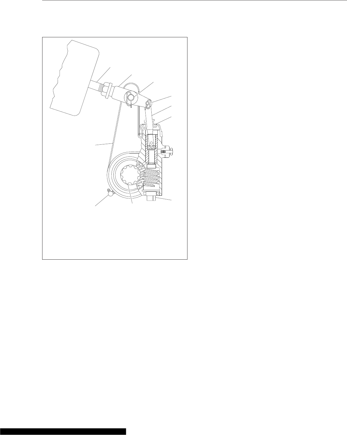
•Inspect slack adjuster boots, if equipped,
for cuts or tears.
•Inspect anchor straps, if equipped, for
damage.
•Look for worn clevis pins on brake cham-
ber pushrods.
•Look for missing or damaged cotter pins
on the clevis pins.
•Ensure chamber piston rods are in line
with the slack adjusters.
Wheel and Tire Inspection
Walk around the vehicle and visually inspect each
wheel and tire assembly.
IMPORTANT: Wheel covers decrease drag force
as a vehicle moves, thereby improving fuel effi-
ciency. If replacement of a wheel cover is nec-
essary, the replacement cover must meet or ex-
ceed the drag reduction performance of the
originally installed cover in order to maintain
compliance with greenhouse gas and full effi-
ciency regulations (GHG14).
1. If the vehicle was originally equipped with wheel
covers, ensure all wheel covers are present. In-
spect wheel covers for damage or wear. Remove
wheel covers from rear drive wheels, if equipped,
prior to inspecting the tires and wheel compo-
nents.
NOTE: During wheel cover installation, ensure
the V-notch in the liner inner retaining ring is
centered on the valve stem. The inner and outer
retaining rings should be uniformly aligned to
each other and to the wheel rim. The outer re-
taining ring of the liner is equipped with two
canvas flaps. When installing the face cover,
make sure the cover retaining ring is inserted
between the two canvas flaps on the liner outer
retaining ring so that the Velcro strips line up
between the face cover and the liner. Make cer-
tain the detachable view cover is centered on
the face cover, and the Velcro strips are
pressed firmly in place.
2. Inspect each tire for the following:
•valve stem caps on every tire, screwed on
finger-tight
•bulges, cracks, cuts, and penetrations
•oil contamination (petroleum derivatives will
soften the rubber and destroy the tire)
•tread depth—if tread is less than 4/32 inch
(3 mm) on any front tire, or less than 2/32
inch (1.5 mm) on any rear tire, replace the
tire
•debris lodged between duel tire sets
IMPORTANT: Low-rolling resistance (LRR) tires
minimize wasted energy as a tire rolls, thereby
decreasing rolling effort and improving fuel effi-
ciency. If tire replacement is necessary, replace-
ment tires must meet or exceed the rolling resis-
tance of the originally installed tires in order to
01/31/2011 f422530
1
2
3
4
5
6
7
8
9
10
1. Grease Fitting (if
equipped)
2. Slack Adjuster
Housing
3. Brake Chamber
Pushrod
4. Clevis
5. Clevis Pin (large)
6. Clevis Pin (small)
7. Actuator Rod
8. Boot
9. Manual Adjusting Nut
10. Camshaft Splines
Fig. 21.3, Meritor Automatic Slack Adjuster
Pre- and Post-Trip Inspections and Maintenance
21.2
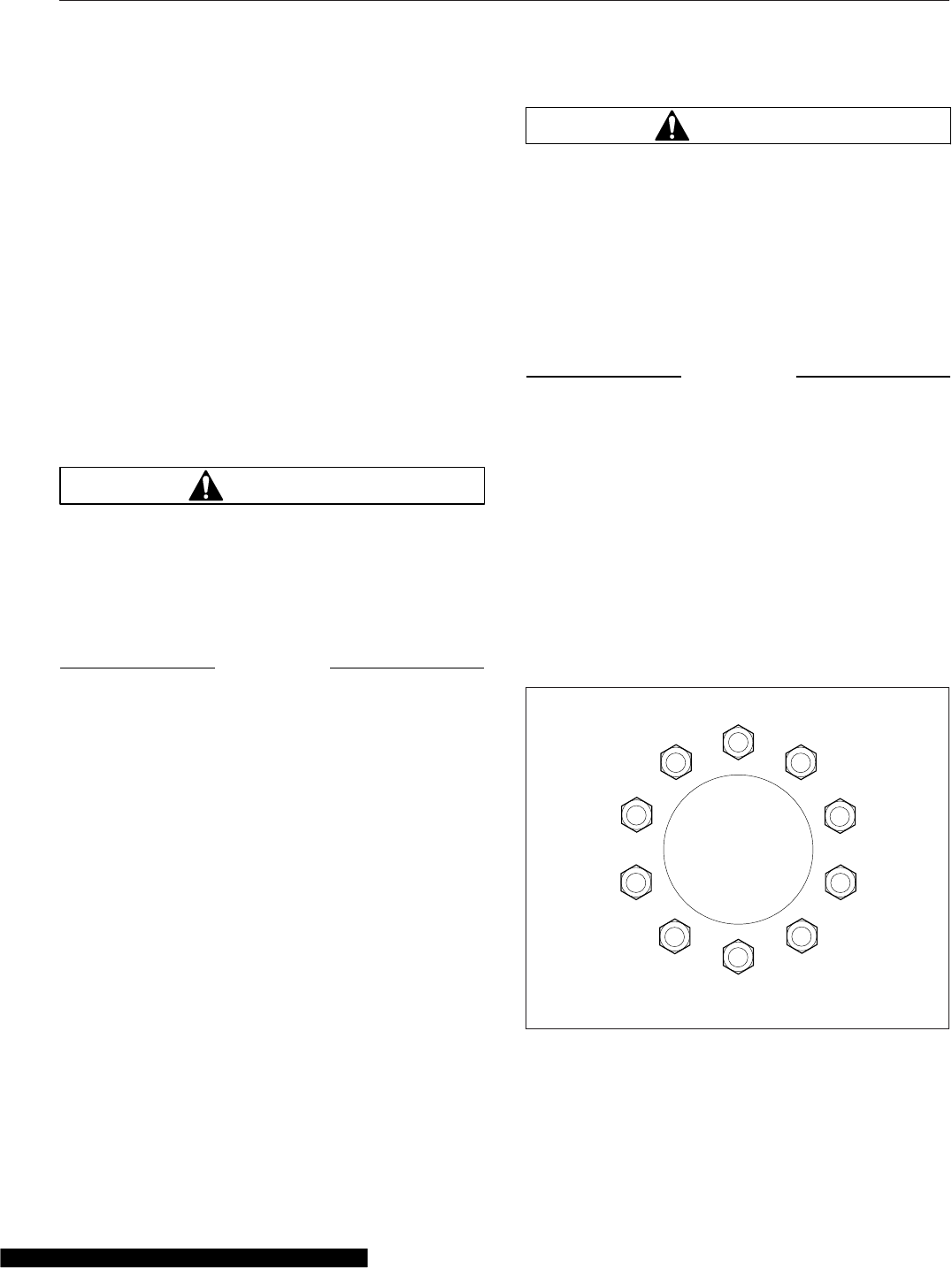
maintain compliance with greenhouse gas and
full efficiency regulations (GHG14).
Contact your tire manufacturer/supplier to deter-
mine the rolling resistance of the originally in-
stalled tires. Visit www.epa.gov/smartway for
additional information and resources.
3. Check tire inflation.
For inflation pressures and maximum loads, see
the tire manufacturer’s guidelines. Inflate the tires
to the applicable pressures if needed.
If a tire has been run flat or under-inflated, check
the wheel and tire for damage before adding air.
Keep compressed air reservoirs and lines dry
during tire inflation. Use well-maintained inline
moisture traps and service them regularly.
WARNING
Do not operate the vehicle with underinflated or
overinflated tires. Incorrect inflation can stress
the tires and make the tires and rims more sus-
ceptible to damage, possibly leading to rim or
tire failure and loss of vehicle control, resulting
in serious personal injury or death.
NOTICE
A weekly pressure loss of 4 psi (28 kPa) or more
in a tire may indicate damage. The tire should be
inspected and, if necessary, repaired or replaced
by a qualified tire service facility.
IMPORTANT: The load and cold inflation pres-
sure must not exceed the rim or wheel manu-
facturer’s recommendations, even though the
tire may be approved for a higher load inflation.
Consult the rim or wheel manufacturer for the
correct tire inflation pressure for the vehicle
load.
4. Examine each rim and wheel component.
4.1 Remove all dirt and debris from the as-
sembly. Rust streaks or metal build-up
around stud holes, or out-of-round or worn
stud holes, may be caused by loose wheel
nuts.
WARNING
Have any worn or damaged wheel components
replaced by a qualified person using the wheel
manufacturer’s instructions and the wheel indus-
try’s standard safety precautions and equipment.
Otherwise a vehicle or workshop accident could
occur, possibly resulting in serious personal in-
jury or death.
4.2 Inspect for broken, cracked, badly worn,
bent, rusty, or sprung rings and rims.
NOTICE
Use the recommended torque values and follow
the proper tightening sequence. Insufficient
wheel nut torque can cause wheel shimmy, re-
sulting in wheel damage, stud breakage, and ex-
treme tire tread wear. Excessive wheel nut torque
can break studs, damage threads, and crack
discs in the stud hole area.
4.3 Make sure all wheel nuts are tightened. If
tightening is necessary, use the tightening
pattern in Fig. 21.4 to initially tighten the
flange nuts to 50 to 100 lbf·ft (68 to 136
N·m). Then tighten the flange nuts to 450
to 500 lbf·ft (610 to 678 N·m).
5. Inspect the outboard side of all wheel hubs and
the hub oil seal area on the inboard side of each
wheel for signs of oil leakage. If any oil is found
f400268
1
10 8
6
4
9
2
7
5
3
04/30/2007
Fig. 21.4, Tightening Pattern, 10-Hole Wheels
Pre- and Post-Trip Inspections and Maintenance
21.3
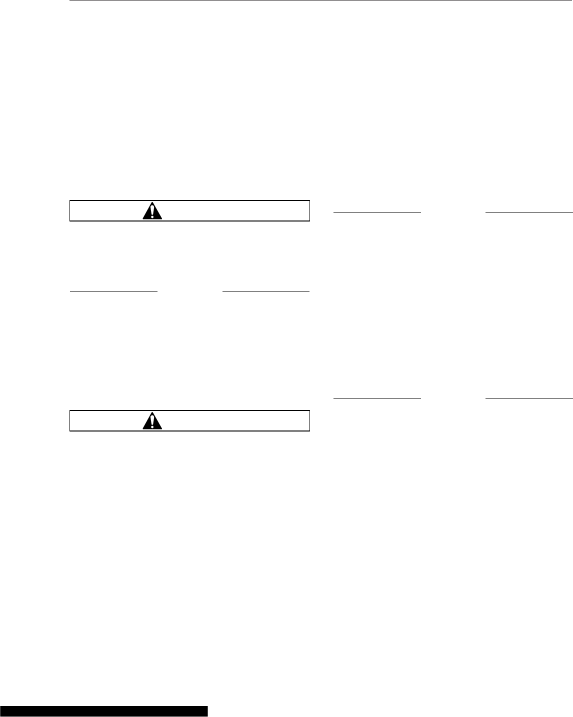
on wheel and tire or brake components, remove
the vehicle from service until the leak has been
fixed.
If needed, fill the hubs to the level indicated on
the hub cap. See Group 35 of the Cascadia
Maintenance Manual for recommended lubri-
cants.
6. Check that mud flaps are undamaged and hang
10 inches (25.4 cm) or less from the ground.
Saddle Tank Areas Inspection
WARNING
When draining the air reservoir, do not look into
the air jets or direct them toward anyone. Dirt or
sludge particles may be in the airstream and
could cause injury.
NOTICE
If the water drained from the air reservoirs is
cloudy or oily, it may indicate a problem with the
compressor. If oil is allowed to contaminate the
air dryer, it will not remove the water from the air
brake system, which could adversely affect brak-
ing.
1. Drain the brake system air reservoirs (reservoirs
without automatic drain valves only).
WARNING
Never operate the engine with the fuel tank shut-
off valves partially closed. This could damage the
fuel pump, causing sudden loss of engine power,
possibly resulting in serious personal injury due
to reduced vehicle control.
2. Ensure fuel tanks are secured to their mounting
brackets and that the mounting brackets are se-
cured to the frame.
If equipped with fuel tank shutoff valves, be sure
the valves are fully open.
3. Inspect visible frame rails for missing bolts, shiny
areas, or rust streaks. Check all visible cross-
members for damage or signs of looseness.
4. Inspect visible components of the exhaust sys-
tem to ensure connections are tight.
Inspect upstream of the aftertreatment device
(ATD), if equipped, for cracking or signs of leaks,
such as soot trails. Inspect downstream of the
ATD for signs of exhaust leaks, such as blister-
ing or warping of nearby components.
Engine Compartment Inspection
1. Check the ground underneath the engine for fuel,
oil, or coolant leaks.
2. Inspect the air intake system for leaks or dam-
age.
NOTICE
Failure to maintain a sealed air intake system
could allow the entry of dirt and contaminants
into the engine. This could adversely affect en-
gine performance and result in engine damage.
2.1 Push the reset button on the air intake
restriction indicator located on the air
cleaner, if equipped.
2.2 Check the air intake duct from the air
cleaner to the engine intake. Make sure
the duct components are secure and air-
tight.
3. Check the engine oil level.
NOTICE
Operating the engine with the oil level below the
minimum fill (or "add") mark or above the maxi-
mum fill (or "full") mark could result in engine
damage.
3.1 Check the oil level with the vehicle parked
on a level surface. See the engine manu-
facturer’s guidelines for engine shutdown
time requirements prior to checking the oil
level.
IMPORTANT: On engines that comply with
EPA07 or newer regulations, use CJ-4 en-
gine oil with less than 1% sulfated ash. Fail-
ure to use CJ-4 oil may void the warranty on
emission aftertreatment components.
3.2 If the oil level is at or below the minimum
fill (or "add") mark on the dipstick, add
enough oil to maintain the level between
Pre- and Post-Trip Inspections and Maintenance
21.4
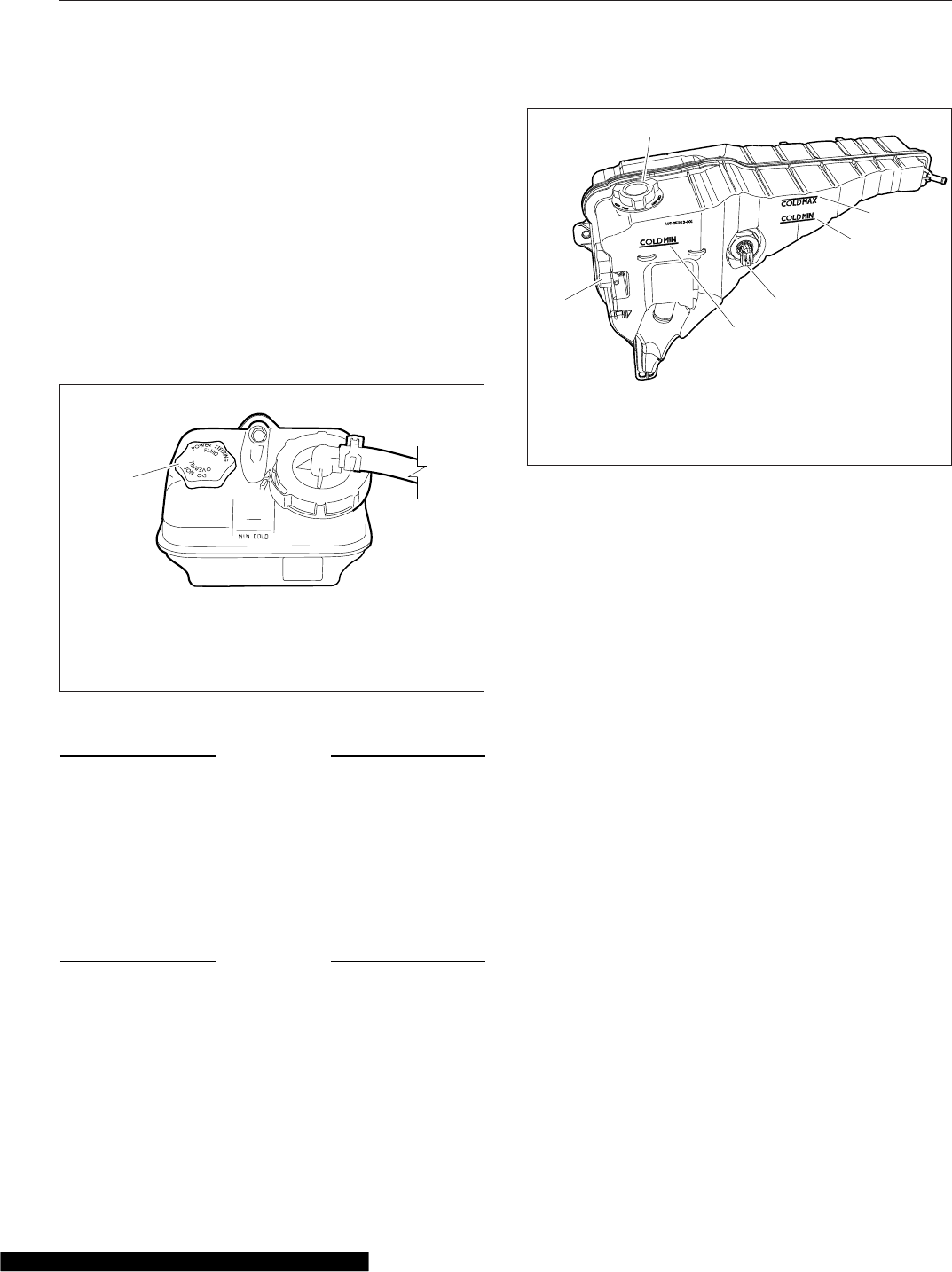
the minimum and maximum fill marks. See
the engine operation manual for recom-
mended lubricants.
For natural gas vehicles, use only Exxon
Busgard® Geo 15W-40 natural gas engine
oil.
4. Check the power steering reservoir fluid level.
The power steering fluid level should be between
the MIN COLD mark and the middle mark just
above it. See Fig. 21.5. If needed, fill the reser-
voir with automatic transmission fluid that meets
Dexron III or TES-389 specifications.
NOTICE
Low coolant could result in engine overheating,
which could cause engine damage.
IMPORTANT: The surge tank must be cool to
check the coolant level.
5. Check the engine coolant level in the radiator
surge tank. See Fig. 21.6.
NOTICE
Coolant must be filled to the COLD MAX line of
the surge tank. Low coolant could result in en-
gine overheating, which could cause engine dam-
age.
5.1 If the coolant is low, fill the surge tank to
the MAX line with a 50/50 mixture of water
and the type of antifreeze currently in-
stalled in your vehicle.
For natural gas vehicles, use only Fleet-
guard ES Compleat™EG Premix 50/50
engine coolant.
5.2 If the surge tank was empty, start the en-
gine after refilling and check the level
again when the engine is at operating
temperature.
6. Inspect visible engine wiring for damage or
looseness. Check for loose wiring, chafed insula-
tion, and damaged or loose hold-down clamps.
7. Inspect visible frame rails for missing bolts, shiny
areas, or rust streaks.
Cab Inspection
1. Push the reset button on the dash-mounted air
intake restriction indicator, if equipped.
2. With the ignition switch in the OFF position,
check the air-pressure warning system.
2.1 If not previously drained, drain the air res-
ervoirs using moderate brake applications
until pressure in both reservoirs is less
than 70 psi (483 kPa).
05/21/2007
1
f462079
NOTE: Typical reservoir shown; configurations may
vary.
1. Filler Cap
Fig. 21.5, Power Steering Fluid Reservoir
1
2
f500390
3
4
4
02/05/2013
5
1. Pressure Relief Cap
2. Filler Cap
3. COLD MAX Fill Line
4. COLD MIN Fill Line
5. Coolant Level Sensor
Fig. 21.6, Coolant Surge Tank
Pre- and Post-Trip Inspections and Maintenance
21.5
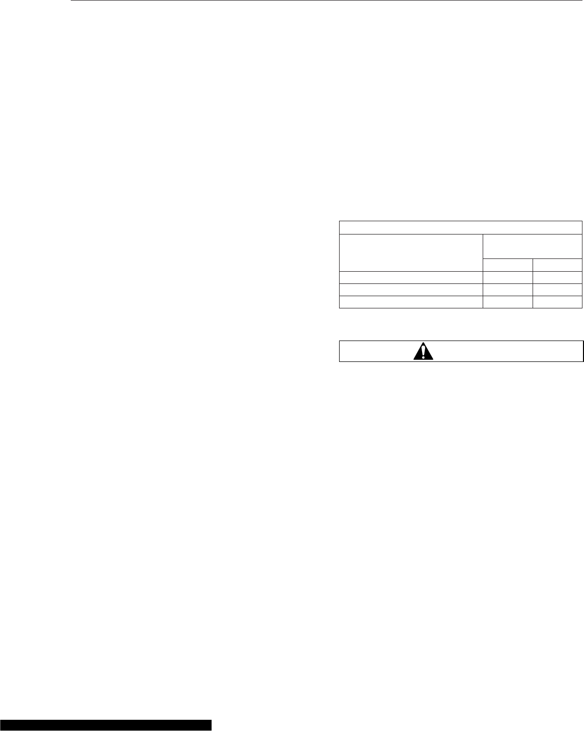
2.2 Turn the ignition to the ON position. The
ICU will complete a full gauge sweep and
bulb check, and an audible warning will
sound. Ensure the low air pressure lamp
(BRAKE AIR) remains illuminated and an
audible warning continues to sound after
the gauge sweep is complete.
3. Check air governor cut-in and cut-out pressures.
3.1 Start the engine and ensure the BRAKE
AIR lamp goes out and the buzzer si-
lences when pressure reaches approxi-
mately 70 psi (483 kPa) in both air reser-
voirs.
The air governor should cut out at ap-
proximately 120 psi (827 kPa). For ve-
hicles with an optional dryer reservoir
module (DRM), the cut-out pressure is
approximately 130 psi (896 kPa).
3.2 With the engine idling, apply the brake
pedal several times. The air governor
should cut in when pressure in the primary
air reservoir (top air gauge) reaches ap-
proximately 100 psi (689 kPa).
4. Check air pressure build-up time.
4.1 With the air system fully charged, make
one full brake application and note the air
pressure reading on the primary air
gauge.
4.2 Further reduce air pressure using moder-
ate brake applications, then run the en-
gine at governed rpm.
4.3 Note the time that the pressure reaches
the previously noted reading on the pri-
mary air gauge, then note the time that
the air pressure reaches cut-out pressure.
4.4 If it takes longer than 30 seconds to reach
cut-out pressure after the primary air
gauge passes the previously noted pres-
sure (noted after one full brake applica-
tion), eliminate any leaks or replace the air
compressor before operating the vehicle.
5. Check air leakage in the system.
5.1 With the parking brake applied, the trans-
mission out of gear, and the air system
fully charged, release the service brakes
and shut down the engine.
5.2 Wait one minute and note the air pressure
drop in psi (kPa) per minute from the pri-
mary air reservoir.
If the pressure drop exceeds the limits
shown in Table 21.1, eliminate any leaks
before operating the vehicle.
6. Check the air pressure reserve.
With the engine still off, make one full brake ap-
plication and observe the pressure drop on the
primary air gauge. If pressure drops more than
25 psi (172 kPa), eliminate any leaks before op-
erating the vehicle.
Maximum Allowable Air Leakage
Description
Pressure Drop:
psi (kPa) Per Minute
Released Applied
Truck or Tractor Only 2 (14) 3 (21)
Truck or Tractor w/Single Trailer 3 (21) 4 (28)
Truck or Tractor w/Two Trailers 5 (35) 6 (42)
Table 21.1, Maximum Allowable Air Leakage
WARNING
When cleaning windshields and windows, always
stand on the ground or on a secure ladder or
platform. Use a long-handled window cleaner. Do
not use the cab steps, tires, fenders, fuel tanks,
engine, or under-hood components to access the
windshield or windows. Doing so could cause a
fall and result in an injury.
7. Inspect the mirrors, window glass, and wind-
shield for cracks or other damage.
8. Ensure that the horn, windshield wipers, and
windshield washers are operating properly.
These devices must be in good working order for
safe vehicle operation.
9. Ensure the heater and defroster are operating
properly.
10. Check the operation of all interior lights.
10.1 Turn on the headlights and leave them on.
Ensure all equipped gauge bulbs illumi-
nate in the dash message center.
10.2 Ensure all equipped driver control
switches illuminate.
Pre- and Post-Trip Inspections and Maintenance
21.6
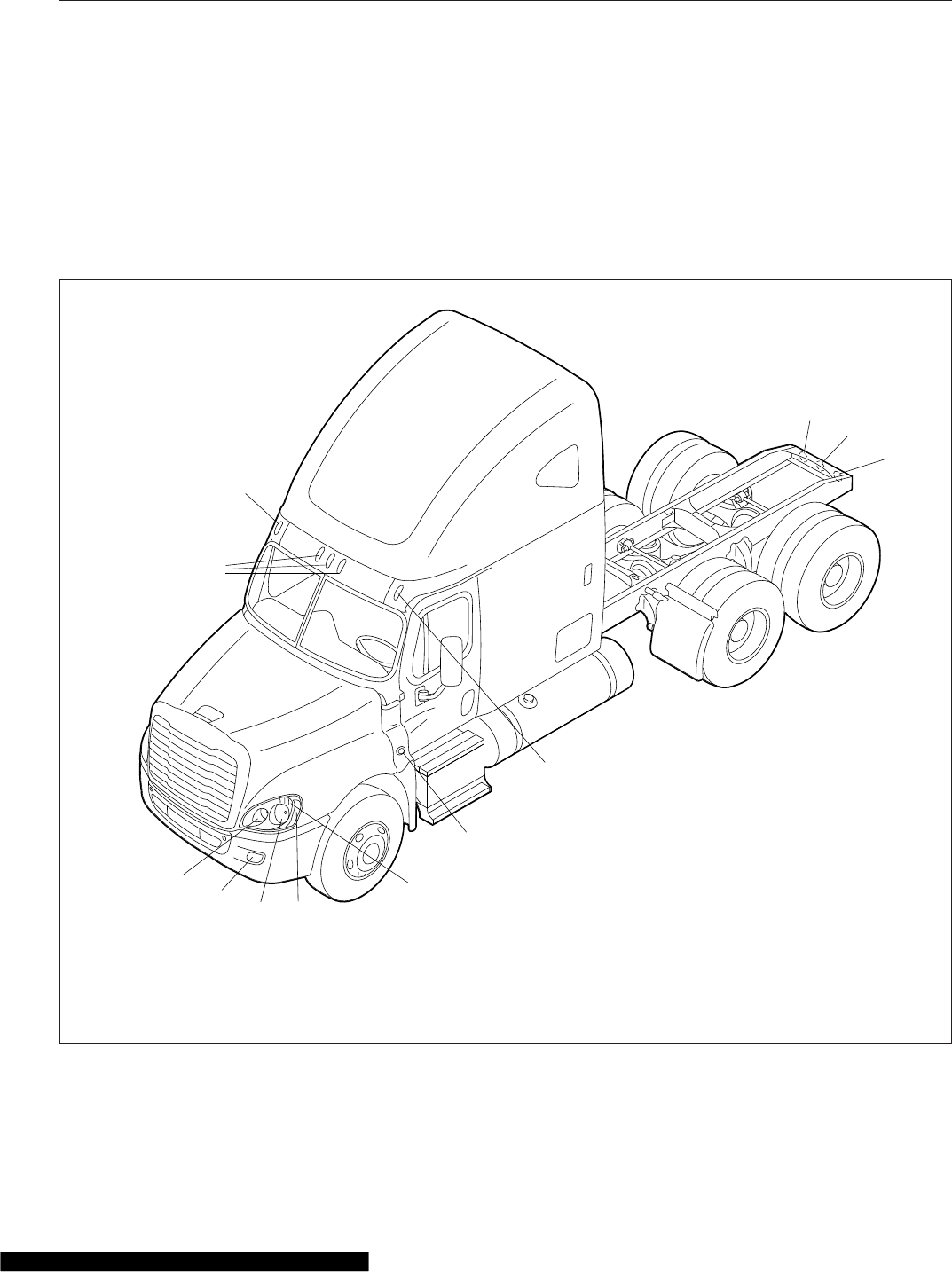
10.3 Ensure both turn signal indicator bulbs
illuminate in the dash message center
when the turn signal switch is activated.
11. Check the operation of all exterior lights. See
Fig. 21.7.
11.1 Activate the high-beam headlights and
hazard warning lights.
11.2 Exit the cab and check that all exterior
lights and reflectors are clean and intact.
11.3 Check that the brake lights, taillights,
headlights, turn signals, marker lights,
identification lights, and clearance lights
are working properly.
12. Inspect the seat belts and tether belts.
02/03/2012 f544971
1
234
6
7
7
8
8
9
10
5
1. High-Beam Headlight
2. Fog Light, or Auxiliary High-Beam Light
3. Low-Beam Headlight
4. Marker Light
5. Turn Signal
6. Side Turn Signal and Marker Light
7. Clearance Light
8. Stop Light, Taillight, and Turn Signal
9. Back-Up Light
10. Identification Light
Fig. 21.7, Exterior Lights
Pre- and Post-Trip Inspections and Maintenance
21.7
WARNING
Inspect and maintain seat belts. When any part of
a seat belt system needs replacement, the entire
seat belt must be replaced, both retractor and
buckle side. Any time a vehicle is involved in an
accident, and the seat belt system was in use,
the entire vehicle seat belt system must be re-
placed before operating the vehicle. Do not at-
tempt to modify the seat belt system; doing so
could change the effectiveness of the system.
Failure to replace worn or damaged seat belts, or
making any modifications to the system, may re-
sult in personal injury or death.
12.1 Check the web for fraying, cuts, extreme
dirt and dust, or for severe fading from
exposure to sunlight, especially near the
buckle latch plate and in the D-loop guide
area.
12.2 Check operation of the buckle, latch, Kom-
fort Latch or Sliding Komfort Latch (if
equipped), web retractor, and upper seat
belt mount on the door pillar. Check all
visible components for wear or damage.
12.3 Check the seat belt and tether belt con-
nection points and tighten any that are
loose.
WARNING
Never fill fuel tanks to more than 95 percent of
their liquid capacity. This could make them more
likely to rupture from impact, possibly causing
fire and resulting in serious personal injury or
death by burning.
Do not mix gasoline or alcohol with diesel fuel.
This mixture could cause an explosion, possibly
resulting in serious personal injury or death. Do
not fill the fuel tanks in the presence of sparks,
open flames, or intense heat. These could ignite
the fuel, possibly causing severe burns.
IMPORTANT: On engines that comply with
EPA07 or newer regulations, use ultralow-sulfur
diesel (ULSD) with 15 ppm sulfur content or
less. Failure to use ULSD fuel may void the
warranty on emission components.
13. Check the fuel level in the fuel tank(s). To keep
condensation to a minimum, fuel tanks should be
filled at the end of each day.
14. Adjust the rearview and down view mirrors as
necessary.
15. Test the service brakes.
15.1 With the engine running and air system
fully charged, set the parking brake.
15.2 Put the vehicle in the lowest gear and
gently attempt to move it forward. The ve-
hicle should not move.
If the vehicle moves, the parking brakes
are not operating correctly and must be
repaired before the vehicle is operated.
16. Test the backup alarm.
16.1 Release the parking brake and put the
transmission in reverse.
16.2 Move the vehicle slightly backward to en-
sure that the backup alarm is operating
correctly.
Natural Gas Fuel System Inspection
WARNING
As with all pressure vessels, CNG/LNG storage
and fuel delivery systems are inherently danger-
ous and should be treated as such. Beyond the
visual inspections listed below, all maintenance
and repairs to compressed natural gas (CNG) or
liquified natural gas (LNG) systems should be
performed by trained personnel. Individuals who
are not trained in all aspects concerning CNG/
LNG fuel delivery systems are not permitted to
service, maintain, test, or inspect a system in any
way. Failure to comply with safety regulations
may lead to fire or explosion, resulting in prop-
erty damage, personal injury, or death.
1. Inspect fuel tanks for dents, scratches, gouges,
or other signs of damage. Inspect the fuel lines
and connections for leaks.
Check that the fuel tanks are securely mounted.
Look for signs of abrasion between components.
CNG Fuel System: Ensure that the CNG fuel cyl-
inder storage box is secured to the frame. In-
spect for signs of looseness.
Pre- and Post-Trip Inspections and Maintenance
21.8
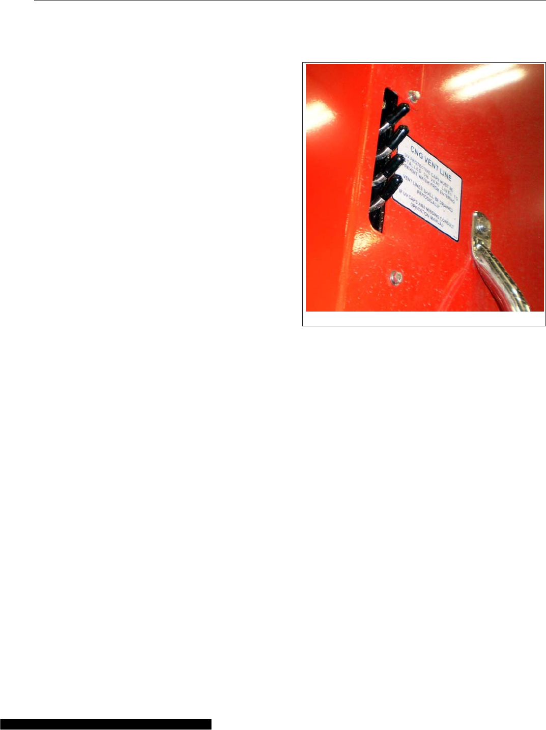
(LNG Fuel System: Ensure that the LNG fuel
tank is secured to the mounting brackets and
that the mounting brackets are secured to the
frame. Ensure all rubber isolator straps are se-
cure around the LNG fuel tank.
2. Check for the presence of all required decals
present in the following locations:
•Gas detection system overhead console;
•Above the door handle on both doors;
•Left front bumper;
•End-of-frame crossmember;
•LNG fuel tank fill port (maximum psi), if
equipped.
3. Check for the presence of vent caps on pressure
relief valves and devices. See Fig. 21.8.Ifany
caps are missing, have the fuel system inspected
by a qualified technician.
CNG Fuel System: Each fuel cylinder should
have two caps (one on each end), which are vis-
ible on the back of the CNG fuel cylinder storage
box. One additional cap is located on the pres-
sure relief valve on the inboard side of the CNG
fuel box, next to the fuel outlet line. If equipped
with saddle tanks, there are also two vent tubes
with caps between the back of the cab and the
back-of-cab fuel tanks.
LNG Fuel System: A red cap should be present
on the secondary relief valve. See Fig. 21.9.
4. Inspect all plumbing components, including the
fuel shutoff valve(s), primary and secondary relief
valves, and the LNG vapor shutoff and excess
flow valves, if equipped, for signs of damage or
leaks. See Fig. 21.9 or Fig. 21.10.
Inspect the fuel fill fitting for signs of damage or
leaks.
Inspect all lines for signs of leaks or damage,
and check all threaded connections.
5. Inspect all fuel gauge components for signs of
leaks or damage. Inspect the fuel level sender
cable and wiring.
6. Inspect all coolant hoses for signs of chafing,
kinks, or leaks. The CNG fuel system utilizes
coolant hoses between the engine and the pres-
sure regulator inside the fuel panel. The LNG
fuel system utilizes coolant hoses between the
engine and the vaporizer.
7. If equipped with an LNG fuel system, check the
fuel tank pressure gauge to ensure that pressure
is within the normal range of 120 to 150 psi (827
to 1034 kPa). If tank pressure exceeds 230 psi
(1586 kPa) and the pressure relief valve does
not open automatically, vent the tank immedi-
ately.
8. Inspect the LNG vaporizer for signs of damage
or leaks. See Fig. 21.9. Inspect the vaporizer
mounting brackets for signs of looseness.
9. On CNG systems, check the low pressure fuel
filter(s) at the engine for contamination.
9.1 Turn the engine off and remove the key
form the ignition.
9.2 Slowly open the drain petcock and drain
any fluid into an appropriate container.
10. When fluid stops, close the drain petcock.
11. Examine the fluid.
02/05/2014 f470618
Fig. 21.8, CNG Vent Line Caps
Pre- and Post-Trip Inspections and Maintenance
21.9
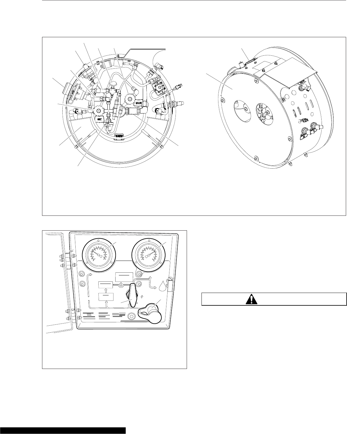
If more than approximately one ounce of oil or
other contaminants is found, have the system
checked at a qualified service center.
Weekly Post-Trip Inspections
and Maintenance
Engine Compartment Inspection
WARNING
Washer fluids may be flammable and poisonous.
Do not expose washer fluid to an open flame or
any burning material, such as a cigarette. Always
comply with the washer fluid manufacturer’s rec-
ommended safety precautions.
1. Check the windshield washer reservoir fluid level.
The reservoir is usually located near the right-
hand frame rail. See Fig. 21.11.
02/04/2014 f470617
1
2
3
689
11
12
4
5
710
1. Pressure Control Regulator
2. Coalescing Filter
3. Fuel Fill Fitting
4. Vapor Shutoff Valve
5. Secondary Relief Valve (red cap)
6. Fill Vent Fitting
7. Primary Relief Valve
8. Tank Pressure Gauge
9. Fuel Shutoff Valve (liquid)
10. Fuel Level Sender Box
11. Cover
12. Fill Check Valve
Fig. 21.9, LNG Tank Plumbing Components
H
IGH
PR
ESS
UR
E
PR
ESS
UR
E
LOW
CYLINDERS
INSPECT CYLINDERS
EVERY 36 MONTHS
OR 36000 MILES
WHICHEVER OCCURS FIRST
NATURAL
GAS
VEHICLE
110 PSIG
ON
MANUAL
SHUT OFF
VALVE
OPEN VALVE
SLOWLY
3600 PSIG MAX.
SERVICE PRESSURE
REGULATOR
FILTER
INSPECT PRESSURE
RELIEF DEVICE
EVERY 2000 MILES
DRAIN HOUSING
EVERY 1500 MILES
REPLACE ELEMENT
EVERY 3000 MILES
12
3
4
04/30/2010 f470556
1. High Pressure Gauge
2. Low Pressure Gauge
3. Manual Fuel Shutoff Valve
4. Fuel Fill Port
Fig. 21.10, CNG Fuel Panel
Pre- and Post-Trip Inspections and Maintenance
21.10
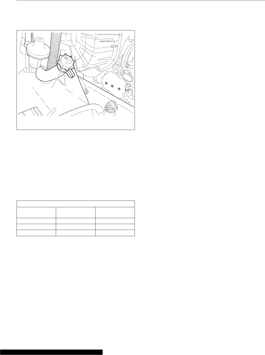
2. After resetting the air intake restriction indicator
during the daily pretrip inspection, check the indi-
cator again with the engine off.
2.1 Check an indicator with graduations to see
if air restriction exceeds the value shown
in Table 21.2.
Check a go/no-go indicator without gradu-
ations to see if the colored bar shows
through the clear window.
Air Intake Maximum Restriction Values (inH
2
O)
Engine Make Pre-EPA07
Engines
EPA07 and
Newer Engines
Cummins 25 25
Detroit 20 22
Mercedes-Benz 22 22
Table 21.2, Air Intake Maximum Restriction Values
2.2 If air restriction exceeds the maximum al-
lowable value, operate the vehicle for one
more day, making sure not to run the en-
gine over rated rpm. Refer to the engine
operation manual for more information on
rated rpm for your engine.
2.3 If air restriction exceeds the maximum
value again, replace the air cleaner. For
instructions, refer to Group 09 of the Cas-
cadia Workshop Manual.
3. Inspect water evacuation components.
3.1 Inspect the vacuator valve(s) installed on
the hood interior and air cleaner. Make
sure the lips of each valve are undam-
aged and pliable, free of debris, and re-
main closed during inspection. See
Fig. 21.12 and Fig. 21.13.
3.2 Inspect the rain tray installed at the base
of the windshield. Ensure that the seal on
the forward edge of the rain tray is in
good condition.
3.3 Inspect the drain hoses installed on the
rain tray. Both hoses should be securely
attached to the rain tray and direct water
down the aft side of the front fenders. See
Fig. 21.14.
4. If the vehicle is equipped with an Allison auto-
matic transmission, check the automatic trans-
mission fluid level.
5. Check for water in the fuel/water separator, if
equipped.
IMPORTANT: When draining fluid from a
fuel/water separator, drain the fluid into an
appropriate container and dispose of it prop-
erly. Many jurisdictions now issue fines for
draining fuel/water separators onto the
ground.
5.1 Place a suitable container under the fuel/
water separator.
NOTE: A hose may be used to direct water
into the container. Use a hose with a ½-inch
pipe thread on DAVCO models.
5.2 If the engine is equipped with a built-in
water separator, loosen the drain valve,
and allow the water to run out. Close the
drain valve, taking care not to overtighten
it.
5.3 Alliance/Racor Models: Turn the drain plug
counterclockwise to open it. See
Fig. 21.15.
DAVCO Models: Remove the vent cap
and open the drain. See Fig. 21.16.
5.4 Stop draining fluid when fuel begins to
drain out.
05/21/2007 f820442
1
1. Washer Fluid Filler Cap
Fig. 21.11, Windshield Washer Reservoir
Pre- and Post-Trip Inspections and Maintenance
21.11
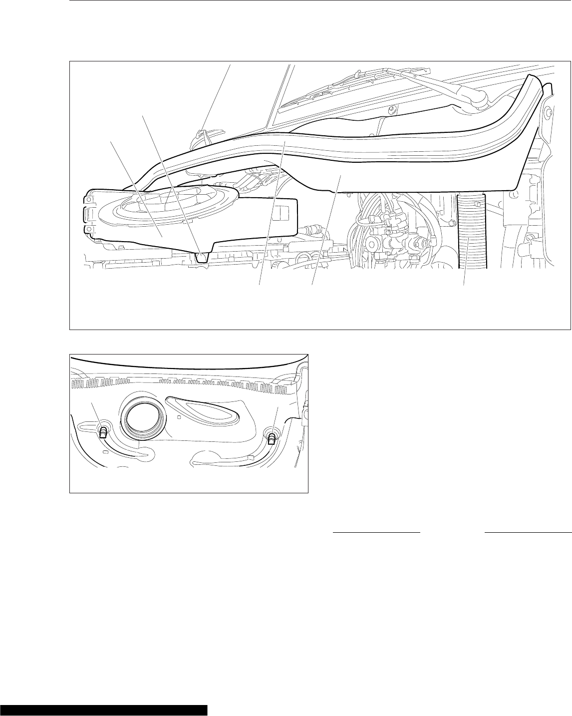
Alliance/Racor Models: turn the drain plug
clockwise to close it.
DAVCO Models: close the drain valve.
Install and hand-tighten the vent cap.
6. Inspect the steering components.
6.1 Inspect tie rods, steering arms, and the
drag link for signs of looseness (i.e., shiny
spots or rust tracks). See Fig. 21.17 for a
rack and pinion steering gear; see
Fig. 21.18 for an integral steering gear.
6.2 Check the steering gear mounting bolts
and pitman arm nut, if equipped, for signs
of looseness.
6.3 Check the drag link nuts for missing cotter
pins.
6.4 Inspect the steering intermediate shaft and
end yokes for excessive looseness or
other damage.
NOTICE
Do not drive with a drive belt that is visibly worn
or damaged. If it fails, the lack of coolant flow
could rapidly cause damage to engine compo-
nents.
7. Inspect the serpentine drive belts for signs of
glazing, frayed edges, breaks, cracks, or oil con-
tamination.
1
2
345
02/17/2012 f090497
1. Air Cleaner
2. Vacuator Valve
3. Rain Tray Seal
4. Rain Tray
5. Drain Hose
Fig. 21.12, Rain Tray Assembly
03/08/2012 f090498
11
1. Vacuator Valves
Fig. 21.13, Hood Interior
Pre- and Post-Trip Inspections and Maintenance
21.12
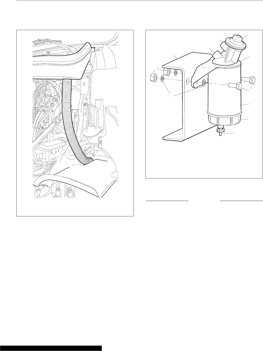
Monthly Post-Trip Inspections
and Maintenance
Brake Component Inspection
Walk around the vehicle and inspect brake system
components for visible damage.
1. Inspect all visible brake system components for
missing fasteners or signs of looseness, such as
rust tracks.
NOTICE
If the external breather tube or breather cap is
missing or incorrectly installed, road dirt and de-
bris can adversely affect the operation of the
brake chamber. Once inside of the chamber, dirt
and debris can cause the internal parts of the
chamber to deteriorate faster.
2. Inspect the exterior surfaces of brake chambers
for damage. Make sure that breather holes are
open and free of debris.
NOTE: Do not route air brake lines on top of
anything likely to be stepped on.
3. Inspect air brake lines for dents, swelling, kinks,
twisting, abrasion, and damage, especially near
moving parts.
4. Inspect flex air lines for deterioration or signs of
abrasion.
02/17/2012 f820466
Ensure drain hoses are securely attached to the rain tray
and drain down the aft side of the front fenders.
Fig. 21.14, Drain Hose
02/03/2010 f470552
1
2
3
4
56
7
8
9
10
11
1. Washers (qty 2)
2. Nuts (qty 2)
3. Frame Rail
4. Fuel Outlet Port
5. Fuel Inlet Port
6. Priming Pump
7. Mounting Head
8. Mounting Bolts (qty 2)
9. Filter Element
10. Sight Bowl
11. Drain Plug
Fig. 21.15, Alliance Fuel/Water Separator Assembly and
Installation
Pre- and Post-Trip Inspections and Maintenance
21.13
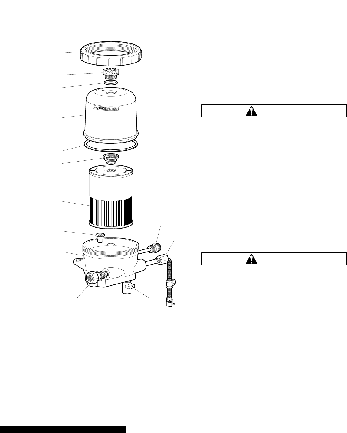
5. Inspect for cracked, worn, or oil-contaminated
brake linings and brake drums (or rotors).
6. Check the thickness of the brake linings. Re-
place brake linings on all brake assemblies on
the axle if any brake linings are worn to less than
approximately 1/4 inch (6.4 mm) at the thinnest
point.
Saddle Tank Areas Inspection
WARNING
When draining the air reservoir, do not look into
the air jets or direct them toward anyone. Dirt or
sludge particles may be in the airstream and
could cause injury.
NOTICE
If the water drained from the air reservoirs is
cloudy or oily, it may indicate a problem with the
compressor. If oil is allowed to contaminate the
air dryer, it will not remove the water from the air
brake system, which could adversely affect brak-
ing.
1. Drain the brake system air reservoirs (reservoirs
with automatic drain valves only).
NOTE: Battery locations vary between vehicles.
2. Inspect the batteries.
WARNING
Battery posts, terminals, and related accessories
contain lead and lead compounds, chemicals
known to the State of California to cause cancer
and reproductive harm. To prevent possible per-
sonal injury, always wash your hands after han-
dling battery parts and related accessories.
2.1 Remove the battery box cover and inspect
all visible battery cables for loose wiring or
damage.
2.2 Check that the battery hold-down is se-
cure.
IMPORTANT: Aerodynamic components de-
crease drag force as a vehicle moves, thereby
improving fuel efficiency. If replacement of an
05/05/2009 f470530
1
2
3
4
5
6
7
8
9
10
11
12
13
1. Inlet Port/Check Valve
2. Lower Housing
3. Bypass Valve
4. Filter Element
5. Spring
6. Cover O-Ring
7. Clear Cover
8. Vent Cap O-Ring
9. Vent Cap
10. Collar
11. 120VAC Pre-Heater
12. 12VDC Pre-Heater
13. Drain Valve
Fig. 21.16, DAVCO Fuel/Water Separator (Fuel Pro 482
shown)
Pre- and Post-Trip Inspections and Maintenance
21.14
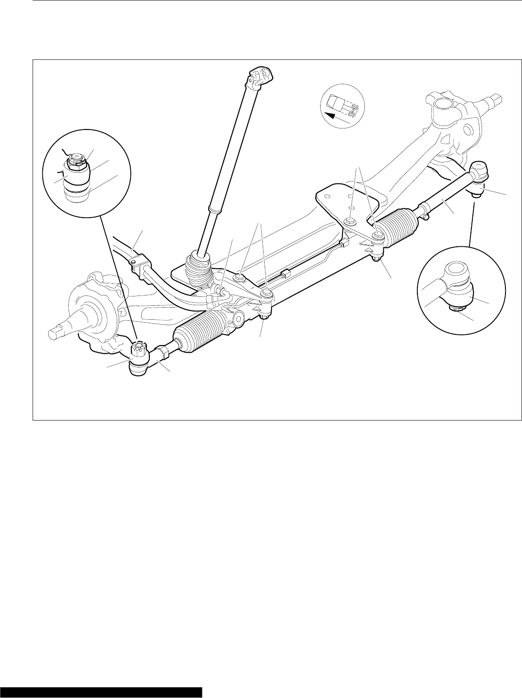
aerodynamic component is necessary, replace-
ment components must meet or exceed the
drag reduction performance of the originally in-
stalled component in order to maintain compli-
ance with greenhouse gas and full efficiency
regulations (GHG14).
3. Inspect the following aerodynamic components, if
equipped, for structural damage, cracks, or wear.
•Chassis fairings
•Roof fairing/deflector
•Side skirts
•Cab/sleeper extenders
•Battery access cover
Engine Compartment Inspection and
Adjustments
IMPORTANT: If replacement of the hood or
bumper is necessary, the replacement compo-
nent must meet or exceed the drag reduction
performance of the originally installed item in
order to maintain compliance with greenhouse
gas and full efficiency regulations (GHG14).
1. Inspect the bumper and hood for structural dam-
age, cracks, or wear.
f462167
07/27/2009
1
1
1
1
2
2
3
3
45
6
6
7
7
1. Steering Tie Rod Arm
2. Castellated Nut
3. Outer Tie Rod
4. Power Steering Fluid Lines
5. Power Steering Fluid Line Fittings
6. Steering Gear Mounting Bolts
7. Steering Gear Mounting Nuts
Fig. 21.17, Rack and Pinion Steering Gear Assembly
Pre- and Post-Trip Inspections and Maintenance
21.15
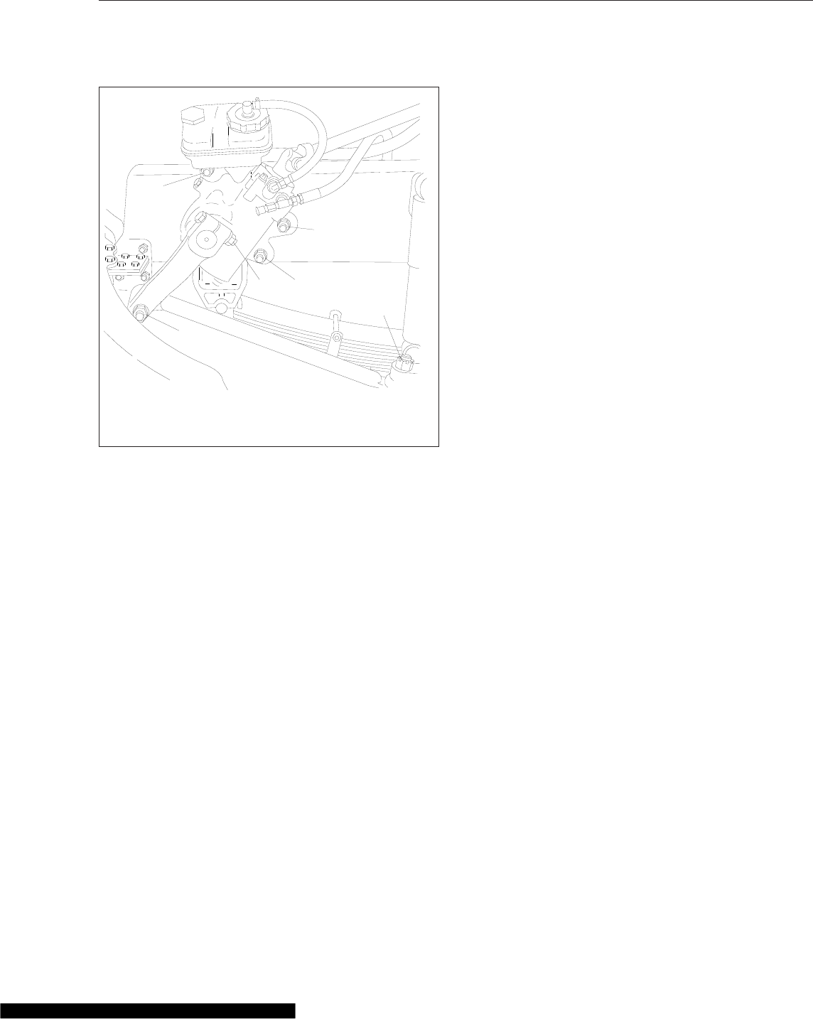
2. Check the hydraulic clutch reservoir, if equipped.
If necessary, add DOT 4 brake fluid.
3. Inspect the radiator and heater hoses, including
the clamps and support brackets.
3.1 Inspect the radiator and charge air cooler
for damage and accumulated debris.
Straighten bent or damaged fins to permit
airflow across all areas of the cores.
NOTE: When traveling through areas of high
insect concentration, it may be necessary to
clean the exterior of the radiator or the
charge air cooler core as often as every 200
miles (320 km).
3.2 Make sure the radiator inlet and outlet
hoses are pliable and are not cracking or
ballooning.
3.3 Make sure the heater hoses are pliable
and are not cracking or ballooning.
3.4 Tighten hose clamps as necessary.
IMPORTANT: Do not overtighten hose
clamps, as hose life can be adversely af-
fected.
3.5 Ensure hose support brackets are se-
curely fastened. Make sure hoses are not
located near sources of wear, abrasion, or
high heat.
IMPORTANT: When replacing hoses, install
service-type knitted or braided yarn-reinforced
neoprene hose. Extended-service-life silicone
hoses may also be used. See the Alliance Parts
Catalog at www.alliancebrandparts.com or
contact your Freightliner Dealer.
4. Check the steering wheel for excessive play.
4.1 Start the engine. With the front tires
straight ahead, turn the steering wheel
until motion is observed at the front
wheels.
4.2 Align a reference mark on the steering
wheel to a rule, then slowly turn the steer-
ing wheel in the opposite direction until
motion is again detected at the wheels.
4.3 Measure the lash (free play) at the rim of
the steering wheel. Excessive lash exists
if steering wheel movement exceeds 2-1/2
inches (64 mm) with a 20-inch (508-mm)
steering wheel, or 2-1/4 inches (57 mm)
with an 18-inch (450-mm) steering wheel.
4.4 If there is excessive lash, check the steer-
ing system for wear or incorrect adjust-
ment before operating the vehicle.
10/11/2001 f461916
1
1
1
2
3
3
1. Steering Gear Mounting Bolts
2. Pitman Arm Pinch Bolt Nut
3. Drag Link Nut
Fig. 21.18, Integral Steering Gear Fasteners
Pre- and Post-Trip Inspections and Maintenance
21.16

22
Cab Appearance
Cab Washing and Polishing ........................................................ 22.1
Care of Fiberglass Parts .......................................................... 22.1
Care of Chrome Parts ............................................................ 22.1
Care of Exterior Lights ............................................................ 22.1
Dashboard Care ................................................................. 22.2
Vinyl Upholstery Cleaning ......................................................... 22.2
Velour Upholstery Cleaning ........................................................ 22.3

Cab Washing and Polishing
IMPORTANT: Carefully read all instructions be-
fore using or applying any cleaner or product on
the vehicle or components. Failure to follow
manufacturers’ recommendations can result in
damage to the finish.
WARNING
Do not power wash or steam clean the engine
bay in the area of vehicle electrical components
such as the SAM Cab, SAM Chassis, or powernet
distribution box. Water intrusion can permanently
damage these components, which could result in
fire, personal injury, or property damage.
To protect the finish of your new vehicle, follow these
guidelines carefully.
•During the first 30 days, rinse your vehicle fre-
quently with water. If the vehicle is dirty, use a
mild liquid soap. Do not use detergent.
•During the first 30 days, do not use anything
abrasive on your vehicle. Brushes, chemicals,
and cleaners may scratch the finish.
•During the first 120 days, do not wax your
vehicle.
To extend the life of your vehicle’s finish, follow these
guidelines.
•Avoid washing your vehicle in the hot sun.
•Always use water. After the cab is completely
washed, dry it with a towel or chamois.
•Do not dust painted surfaces with a dry cloth,
as this will scratch the paint.
•Do not remove ice or snow from a painted sur-
face with a scraper of any sort.
•To prevent damage to the finish, wax it regu-
larly. Before waxing, if the finish has become
dull, remove oxidized paint using a cleaner
specifically designed for this purpose. Remove
all road tar and tree sap before waxing.
Freightliner recommends that a quality brand of
cleaner or cleaner-polish and polishing wax be
used.
•Do not let diesel fuel or antifreeze stand on a
painted surface. If either should occur, rinse
the surface off with water.
•To prevent rust, have any nicks or other dam-
age on the finish touched up as soon as pos-
sible.
•Park your vehicle in a sheltered area whenever
possible.
Care of Fiberglass Parts
Wash unpainted fiberglass air fairings and shields
monthly with a mild detergent, such as dishwashing
liquid. Avoid strong alkaline cleansers.
Apply a wax specifically designed for fiberglass.
Care of Chrome Parts
To prevent rust, keep chrome parts clean and pro-
tected at all times. This is especially important during
winter driving and in coastal areas where there is
exposure to salt air.
When cleaning chrome parts, use clean water and a
soft cloth or sponge. A mild detergent may also be
used.
Sponge gently, then rinse. If necessary, use a non-
abrasive chrome cleaner to remove stubborn rust or
other material. Do not use steel wool.
To help protect the chrome after cleaning, apply a
coat of polishing wax to the surface. Never use wax
on parts that are exposed to high heat, such as ex-
haust pipes.
Care of Exterior Lights
Clean the headlight lenses by hand only, using a
flannel cloth with mild, non-caustic soap or detergent,
and water.
CAUTION
Do not use a power buffer, paper towels, chemi-
cal solvents, or abrasive cleaners on the head-
light lens, all of which can remove the UV coating
from the surface, and result in yellowing of the
lens.
Cab Appearance
22.1

Dashboard Care
NOTICE
When cleaning the dashboard, instrument panel,
or gauge lens covers, do not use Armor-All Pro-
tectant®, STP Son-of-a-Gun®, window cleaner, or
other equivalent treatments. These cleaners con-
tain vinyl plasticizers which can cause stress
crazing in the interior plastic panels and can re-
sult in cracking of the panels. Some cleaners can
also have an adverse effect on the clear plastic
of instrument panels and gauge lens covers, re-
sulting in a foggy or cloudy appearance. This
type of damage is not covered by vehicle war-
ranty.
To clean the dashboard, instrument panel, and gauge
lens covers, use a cloth dampened with warm soapy
water. Make certain to wring the cloth out well before
cleaning, as excess water will damage the electrical
components.
Vinyl Upholstery Cleaning
To prevent soiling, frequent vacuuming or light brush-
ing to remove dust and dirt is recommended. Harsh
cleaning agents can cause permanent damage to
vinyl upholstery. To preserve the upholstery and pre-
vent damage, carefully review the following sections
for recommended cleaning procedures. Waxing or
refinishing improves soil resistance and cleanability
for all vinyls. Any hard wax, such as that used on
automobiles, may be used.
Ordinary Dirt
Wash the upholstery with warm water and mild soap,
such as saddle or oil soap. Apply soapy water to a
large area and allow to soak for a few minutes, then
rub briskly with a cloth to remove the dirt. This can
be repeated several times, as necessary.
If dirt is deeply imbedded, use a soft bristle brush
after applying the soap.
If dirt is extremely difficult to remove, wall-washing
preparations normally found around the home can be
used. Powdered cleaners, such as those used for
sinks and tiles, are abrasive and must be used with
caution as they can scratch the vinyl or give it a per-
manent dull appearance.
Chewing Gum
Harden the gum with an ice cube wrapped in a plas-
tic bag, then scrape it off with a dull knife. Any re-
maining traces of gum can be removed with an all-
purpose light oil (peanut butter will also work) and
wiped off.
Tars, Asphalts, and Creosote
Each of these items stains vinyl after prolonged con-
tact. They should be wiped off immediately and the
area carefully cleaned, using a cloth dampened with
naphtha.
Paint, Shoe Heel Marks
Paint should be removed immediately. Do not use
paint remover or liquid-type brush cleaner on vinyl.
An unprinted cloth, dampened with naphtha or tur-
pentine may be used. Use care to prevent contact
with parts of the upholstery that are not vinyl.
Sulfide Stains
Sulfide compounds, such as those found in eggs and
some canned goods, can stain after prolonged con-
tact with vinyl. These stains can be removed by plac-
ing a clean, unprinted piece of cloth over the spotted
area and pouring a liberal amount of 6 percent hy-
drogen peroxide onto the cloth. Allow the saturated
cloth to remain on the spot for 30 to 60 minutes. For
stubborn spots, allow the hydrogen-peroxide satu-
rated cloth to remain on the area overnight. Use cau-
tion to prevent the solution from seeping into the
seams, or it will weaken the cotton thread.
Nail Polish and Nail Polish Remover
Prolonged contact with these substances causes per-
manent damage to vinyl. Careful blotting immediately
after contact minimizes damage. Do not spread the
liquid during removal.
Shoe Polish
Most shoe polishes contain dyes which penetrate
vinyl and stain it permanently. Shoe polish should be
wiped off as quickly as possible using naphtha or
lighter fluid. If staining occurs, try the procedure used
for sulfide stains.
Cab Appearance
22.2

Ball Point Ink
Ball point ink can sometimes be removed if rubbed
immediately with a damp cloth, using water or rub-
bing alcohol. If this does not work, try the procedure
used for sulfide stains.
Miscellaneous
If stains do not respond to any of the treatments de-
scribed above, it is sometimes helpful to expose the
vinyl to direct sunlight for up to 30 hours. Mustard,
ball point ink, certain shoe polishes, and dyes often
bleach out in direct sunlight, leaving the vinyl undam-
aged.
Velour Upholstery Cleaning
To prevent soiling, frequent vacuuming or light brush-
ing to remove dust and dirt is recommended. Spot
clean with a mild solvent or an upholstery shampoo,
or the foam from a mild detergent. When using a sol-
vent or a dry-cleaning product, follow the instructions
carefully, and clean only in a well-ventilated area.
Avoid any product that contains carbon tetrachloride
or other toxic materials. With either method, pretest a
small area before proceeding. Use a professional
upholstery cleaning service when extensive cleaning
is needed.
Grease and Oil-Based Stains
Dampen a small absorbent cloth with dry-cleaning
solvent or spot remover. Apply the cloth carefully to
the spot from the outer edge to the center. Pat and
blot the spot with a clean, dry cloth. Repeat several
times, as necessary, turning the cloths so that the
stain does not redeposit on the fabric.
Sugar and Water-Based Stains
Apply water-based detergent or cleaner, working in
circular motions. Pat and blot as dry as possible. Re-
peat, if necessary, before drying thoroughly.
Chewing Gum or Wax
Harden the gum or wax with an ice cube wrapped in
a plastic bag, then scrape it off with a dull knife. Ex-
cess wax can be absorbed by placing a thick white
blotter over the wax and heating with a warm (not
hot) iron. Remove the remainder by using the proce-
dure for grease and oil-based stains.
Mildew
Brush the dry fabric with a soft brush. Sponge with
detergent, and blot. If the fabric is colorfast, dilute a
teaspoon of bleach in one quart (one liter) of cool
water. Apply with a swab, directly on the mildew
stain. Dab repeatedly with clear, cool water, and blot
dry.
Cab Appearance
22.3

23
Headlight Aiming
Preliminary Checks ............................................................... 23.1
Checking Headlight Aim ........................................................... 23.1
Adjusting Headlight Aim ........................................................... 23.1
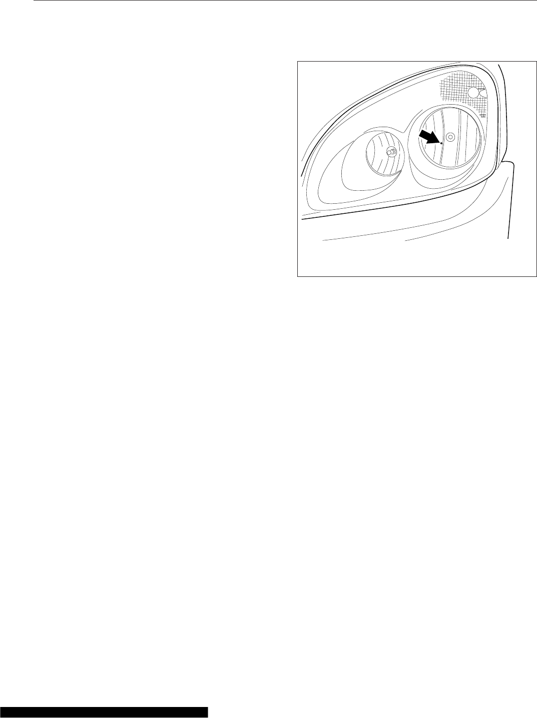
Preliminary Checks
Before checking or adjusting the headlight aim, do
the following.
•Check that the hood is closed and latched.
•Remove any large amounts of mud or ice from
the underside of the fenders.
•Check the springs for sagging or broken
leaves.
•Check the suspension for proper functioning of
the leveling mechanism. On cabs with air sus-
pensions, make sure that the height is properly
adjusted.
•Check for damage to the hood and hinge as-
sembly. Repair as necessary.
•With the vehicle unloaded, check that the tires
are inflated to the recommended air pressure.
•Clean the headlight lenses. Use a soft cloth
with mild, non-caustic soap or detergent, and
water.
Checking Headlight Aim
1. Park the vehicle on a level surface, 25 ft (7.6 m)
away from, and perpendicular to, a vertical
screen or wall. Shut down the engine and set the
parking brake. Chock the tires.
2. Each headlight has a height adjusting dot. See
Fig. 23.1. Measure the distance from the ground
to the height adjusting dot on each headlight
(Fig. 23.2, Item A). Note those distances.
3. On the screen or wall, mark the locations of each
headlight bulb center using the distances found
in step 2. See Fig. 23.2, Items 2 and 3.
4. Turn on the low-beam headlights.
5. Check the vertical adjustment of the low beams.
The center of each beam projection should fall
on or near the marks made during step 3. See
Fig. 23.3.
6. Use Table 23.1 to determine the maximum verti-
cal distance allowable between the marks on the
wall and the center of each low-beam projection.
If the distance between either projection center
and the mark made on the wall or screen is
greater than the maximum distance given in
Table 23.1, adjust the vertical positioning of that
headlight.
Adjusting Headlight Aim
NOTE: Freightliner vehicles are offered with
various headlight assembly options. Because of
the various options, the location of adjustment
screws on your vehicle’s headlight assembly
may vary from what is shown here.
The adjusting screw is located on the lower outside
corner of the headlight assembly. See Fig. 23.4. Turn
the adjusting screw clockwise to raise the beam and
counterclockwise to lower it, until the beam pattern
meets the acceptable standard.
01/23/2012 f545869
Measure beam height from the ground to the small dot
roughly in the center of the headlight lens.
Fig. 23.1, Headlight Beam Height Adjusting Dot
Headlight Aiming
23.1
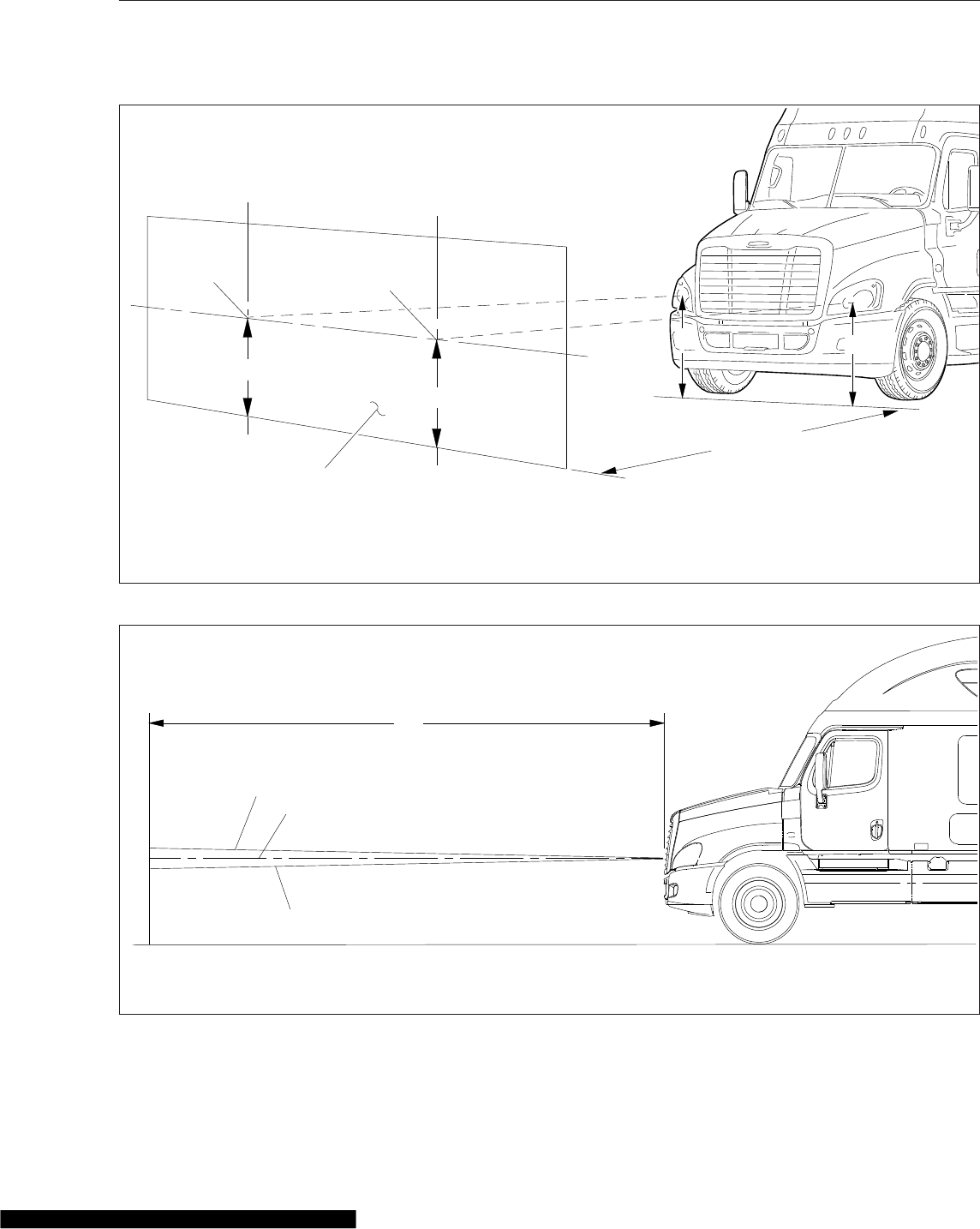
f545850a01/10/2012
B
B
1
23
25 ft (7.6 m)
A
A
A. Measure the distance from the ground to the center of each headlight bulb.
B. Mark where the center of each headlight projection should appear.
1. Screen or Wall
2. Center of Right-Hand Headlight Projection
3. Center of Left-Hand Headlight Projection
Fig. 23.2, Headlight Aiming Screen/Wall
01/10/2012 f545851a
A
1
2
3
1. Low-Beam Angle Upper Limit
2. Ideal Low-Beam Projection
3. Low-Beam Angle Lower Limit
Fig. 23.3, Vertical Low-Beam Headlight Variation Limits
Headlight Aiming
23.2
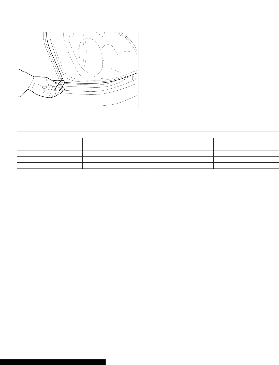
Vertical Low-Beam Headlight Variation Limits
Distance Between Ground
and Headlight: in (mm)
Desired Variation (Fig. 23.3,
Item 2): in (mm)
Upper Limit (Fig. 23.3, Item
1): in (mm) up
Lower Limit (Fig. 23.3, Item
3): in (mm) down
22–36 (560–900) 0 3.9 (100) 3.9 (100)
36–48 (900–1200) 2 (50) down 2 (50) 6 (150)
48–54 (1200–1400) 2.5 (64) down 1.6 (40) 6.5 (165)
Table 23.1, Vertical Low-Beam Headlight Variation Limits
06/18/2007 f545076
Fig. 23.4, Headlight Adjusting
Headlight Aiming
23.3

24
In an Emergency
Hazard Warning Lights ............................................................ 24.1
Fire Extinguisher ................................................................. 24.1
Emergency Kit, Optional .......................................................... 24.1
Emergency Filter Replacement, Davco ............................................... 24.1
Emergency Starting With Jumper Cables ............................................. 24.2
Towing ......................................................................... 24.4
Fire in the Cab .................................................................. 24.7
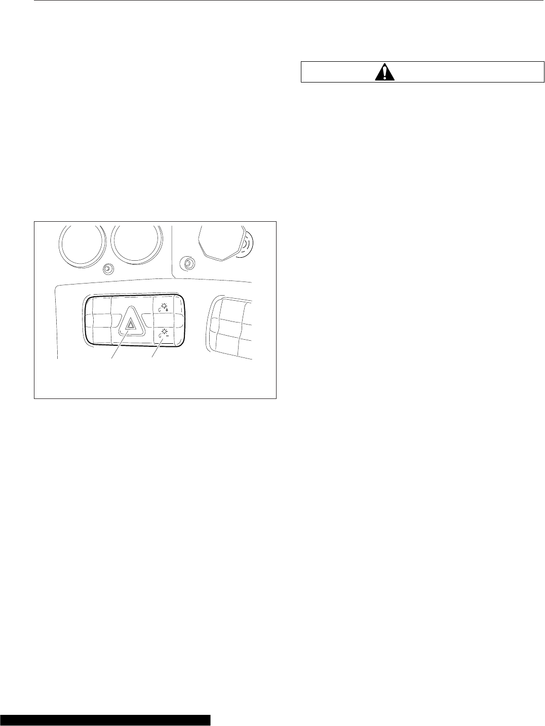
Hazard Warning Lights
The hazard warning light switch is located on the
dash in what is referred to as the master module.
See Fig. 24.1. The hazard lights can be activated
regardless of the ignition switch position.
To activate the hazard lights, push the center of the
switch once. The switch will blink at the same rate
that the hazard lights flash. Push the switch again to
turn them off. All the turn signal lights on the vehicle
and trailer, as well as the turn signal indicators in the
ICU, flash simultaneously when the hazard lights are
activated.
Fire Extinguisher
A fire extinguisher is located either in the cab by the
driver’s door, or in the baggage compartment.
Emergency Kit, Optional
An optional emergency kit is located in the cab. The
kit includes one or more of the following: a first aid
kit, a reflective vest, a triangular reflector, a flare kit,
and (on vehicles with a Davco fuel/water separator) a
spin-on fuel filter element.
If there is an emergency while driving, cautiously pull
off the road. Turn on the hazard warning lights. Place
the flares and reflector along the side of the road to
alert other drivers that an emergency situation exists.
WARNING
Use extreme care when placing flares in emer-
gency situations that involve exposure to flam-
mable substances such as fuel. An explosion or
fire could occur causing serious personal injury.
Emergency Filter
Replacement, Davco
If the filter cover on the Davco fuel/water separator is
broken, it will not be possible to operate the vehicle.
A standard spin-on filter will correct this problem.
Refer to the Davco web site (www.davcotec.com)
for additional information.
To replace the filter on all Davco fuel/water separa-
tors, follow this procedure:
1. Drain the fuel until it is below the level of the col-
lar. See Fig. 24.2 for the model 232/233 fuel/
water separator and Fig. 24.3 for the model 382
fuel/water separator.
2. Remove the vent and seal.
NOTE: The vent and seal are not needed in the
emergency replacement. They should be re-
tained for later installation at the time when the
cover is replaced.
3. Remove the collar using the DAVCO fuel-water
separator wrench. Do not use pliers or channel-
lock pliers.
4. Remove the cover, cover seal, and spring. Re-
tain them for later assembly.
5. Remove the filter element and dispose of it prop-
erly.
NOTE: Remove the rubber grommet from the
stud.
6. Install the standard engine spin-on filter (included
in the emergency kit) on the threaded stud.
7. Install the cover, cover seal, and spring, as re-
moved.
8. Install the collar over the cover. Tighten the collar
finger-tight.
9. Start the engine and run it at increased rpm for
one minute to purge air from the fuel lines.
03/20/2007 1f610855
2
1. Hazard Warning Switch
2. Panel Lamps Switch
Fig. 24.1, Master Module
In an Emergency
24.1
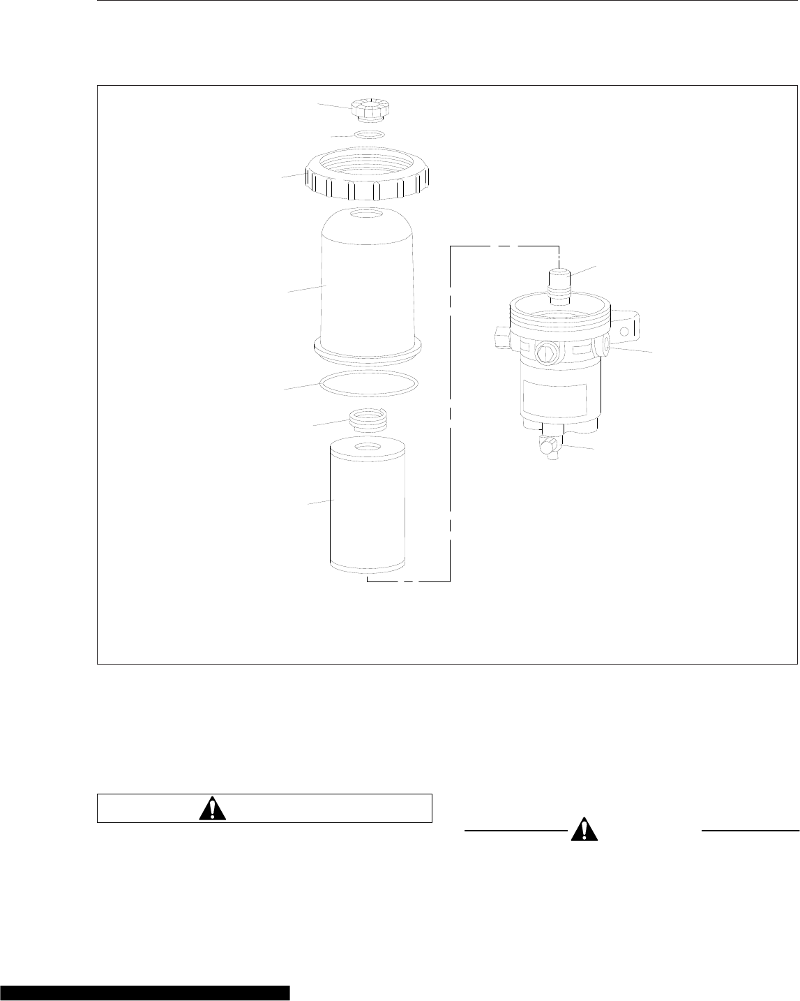
Emergency Starting With
Jumper Cables
When using jumper cables, follow the instructions
below.
WARNING
Batteries release explosive gas. Do not smoke
when working around batteries. Put out all flames
and remove all sources of sparks or intense heat
in the vicinity of the battery. Do not allow the ve-
hicles to touch each other. Do not lean over the
batteries when making connections, and keep all
other persons away from the batteries. Failure to
follow these precautions could lead to severe
personal injury as a result of an explosion or
acid burns.
CAUTION
Make sure both electrical systems are the same
voltage. Electronic devices on both vehicles can
f470416
11/14/2001
1
2
3
4
5
6
7
8
10
9
1. Vent
2. Seal
3. Collar
4. Cover
5. Cover Seal
6. Spring
7. Filter Element
8. Threaded Stud
9. Fuel Port
10. Drain
Fig. 24.2, Davco Model 232 and 233 Fuel/Water Separator
In an Emergency
24.2
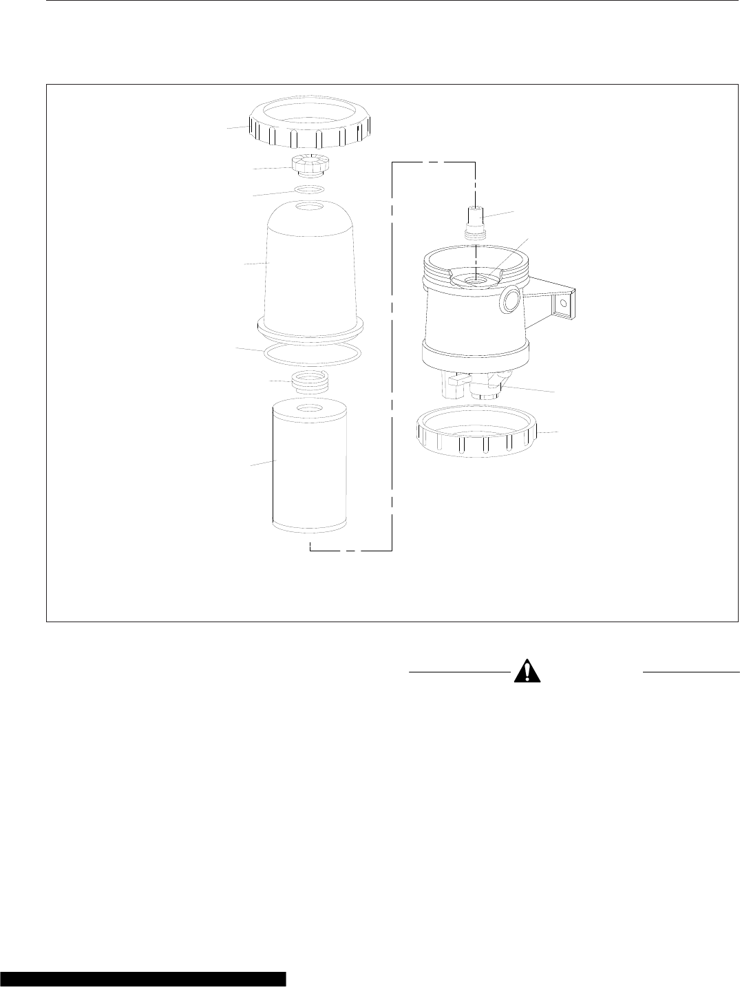
be damaged when connected to a vehicle with a
different operating voltage.
NOTE: On vehicles equipped with optional un-
derhood jump start posts, connect to these
posts instead of the batteries.
1. Apply the parking brakes and turn off the lights
and all other electrical devices.
2. Remove the battery box cover by pulling on the
end of each hold-down latch until the end clears
the catch, then pivoting the latches out of the
way, and lifting off the cover. See Fig. 24.4.
CAUTION
Always connect the battery, jumper cables, and
charger correctly (positive-to-positive and
negative-to-negative). Connecting a charging de-
vice backwards (positive-to-negative) can se-
verely damage the vehicle electrical content and
cause non-warrantable failures.
3. Connect the positive (+) jumper cable to the
positive battery post on the Cascadia needing
the jump start, then connect the other end of the
positive jumper cable to the positive battery or
f470417
1
2
4
6
7
5
8
11/14/2001
3
9
11
10
1. Collar
2. Vent
3. Seal
4. Cover
5. Cover Seal
6. Spring
7. Filter Element
8. Threaded Stud
9. Fuel Port
10. Drain
11. Bottom-Plate Collar
Fig. 24.3, Davco Model 382 Fuel/Water Separator
In an Emergency
24.3
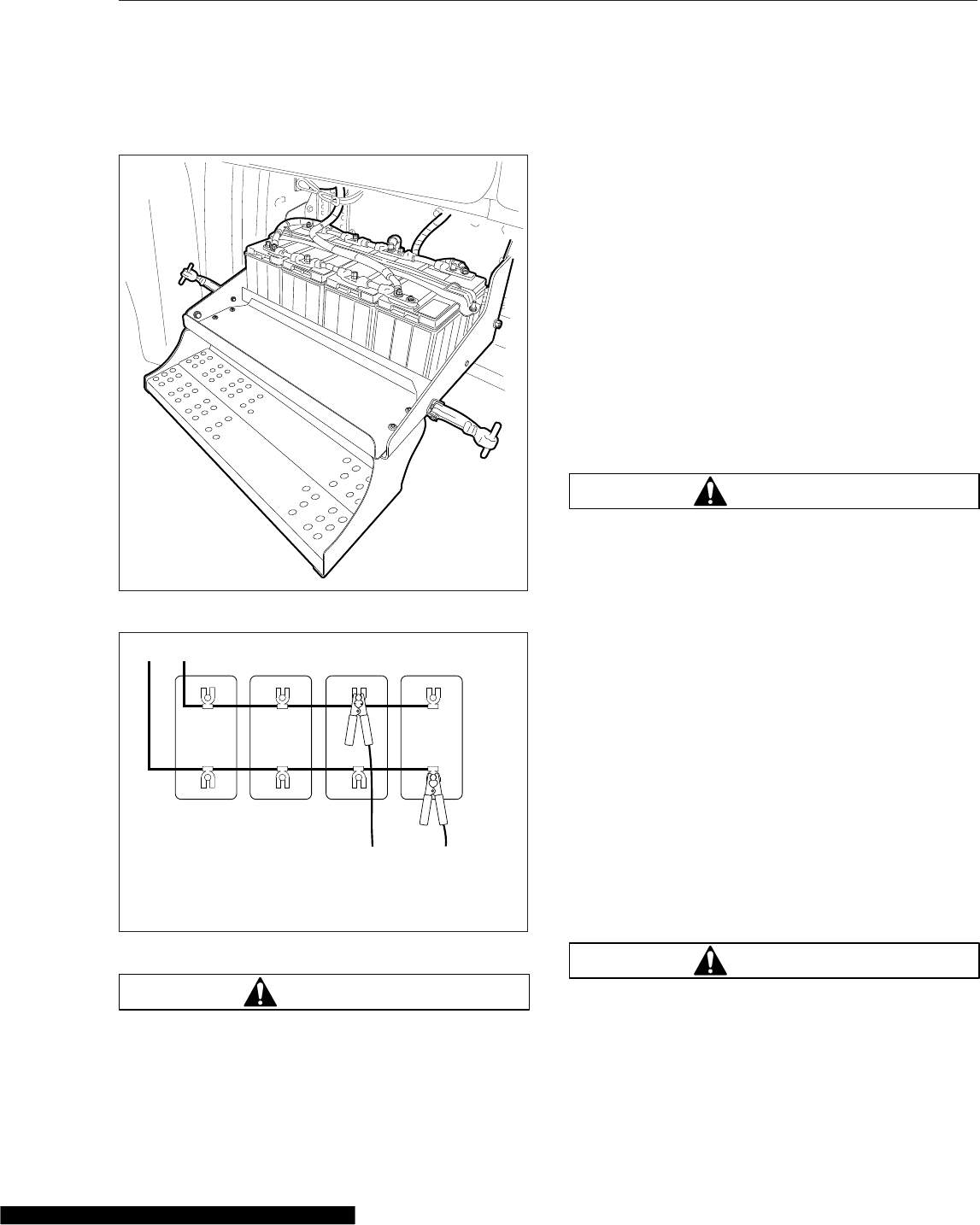
jump start post of the vehicle providing the jump.
See Fig. 24.5.
WARNING
Do the next step exactly as instructed and do not
allow the clamps of one cable to touch the
clamps of the other cable. Otherwise, a spark
could occur near a battery, possibly resulting in
severe personal injury from explosion or acid
burns.
4. Connect one end of the second jumper cable to
the negative terminal of the booster battery, and
connect the other end of the cable to to the
negative battery post of the Cascadia needing
the jump start.
5. Start the engine of the vehicle with the booster
batteries, and let the engine run a few minutes to
charge the batteries of the other vehicle.
6. Attempt to start the engine of the vehicle with the
batteries receiving the charge. Do not operate
the starter longer than 30 seconds, and wait at
least two minutes between starting attempts to
allow the starter to cool.
7. When the engine starts, let it idle a few minutes.
WARNING
Do the next step exactly as instructed and do not
allow the clamps of one cable to touch the
clamps of the other cable. Otherwise, a spark
could occur near a battery, possibly resulting in
severe personal injury from explosion or acid
burns.
8. Disconnect the grounded cable from the frame or
other non-battery location, then disconnect the
other end of the cable.
9. Disconnect the remaining cable from the newly
charged battery (or jump-start post if equipped)
first, then disconnect the other end.
10. Install the cover; be sure it is positioned properly
before fastening the latches.
Towing
When it is necessary to tow the vehicle, make sure
the instructions below are closely followed to prevent
damage to the vehicle.
WARNING
Do not tow an unbraked vehicle if the combined
weight of both vehicles is more than the sum of
06/12/2007 f545070
Fig. 24.4, Battery Compartment
+
−
+
−
f545111
07/06/2007
+
−
+
−
AB
CD
A. – Battery Cable to Vehicle
B. + Battery Cable to Vehicle
C. + Jumper Cable (connect first and disconnect last)
D. – Jumper Cable (connect last and disconnect first)
Fig. 24.5, Jumper Connections
In an Emergency
24.4
the gross axle weight ratings (GAWR) of the tow-
ing vehicle. Otherwise brake capacity will be in-
adequate, which could result in personal injury or
death.
Front Towing Hookup
1. Disconnect the battery ground cables.
NOTICE
Failure to remove the axle shafts when towing
the vehicle with the rear wheels on the ground
will result in damage to the transmission and
other drivetrain components.
2. Remove both drive axle shafts. On dual drive
axles, if the vehicle is to be lifted and towed, re-
move only the rearmost drive axle shafts.
On vehicles equipped with an air fairing, remove
both the forward and rearmost drive axle shafts if
there is insufficient towing clearance.
3. Cover the ends of the hubs with metal plates or
plywood cut to fit the axle opening, and drilled to
fit the axle shaft studs. This prevents lubricant
from leaking out and will keep contaminants from
getting into and damaging the wheel bearings
and axle lubricant.
NOTICE
Failure to protect the frame rails from the chains
could cause damage, leading to eventual frame
failure.
4. On dual drive axles, if the vehicle is to be lifted
and towed, chain the forward rear-axle assembly
to the vehicle frame. Use protection to keep the
chains from damaging the frame.
5. Remove the bumper end caps and chrome bum-
per (if equipped).
6. Attach the towing device. Do not pass a sling (for
example, a rope or chain) from one tow hook to
another to fasten for towing. Known as reeving,
this practice is not permissible in most industrial
applications of towing and hoisting. Reeving can
overload the hooks and result in damage to the
vehicle. See Fig. 24.8.
7. Lift the vehicle and secure the safety chains. If
extra towing clearance is needed, remove the
front wheels.
NOTE: Due to the many variables that exist in
towing, positioning the lifting and towing device
is the sole responsibility of the towing-vehicle
operator.
8. Connect the clearance lights, taillights, and sig-
nal lights. Connect any special towing lights re-
quired by local regulations.
WARNING
Failure to chock the tires or connect the tow
truck’s air brake system before releasing the
spring parking brakes could allow the disabled
vehicle to suddenly roll. This could cause prop-
erty damage or personal injury.
9. Chock the tires on the disabled vehicle and con-
nect the towing vehicle’s air brake system to the
vehicle being towed. Then, release the spring
parking brakes and remove the chocks.
Rear Towing Hookup
NOTICE
Using a rear towing hookup on a vehicle
equipped with a roof fairing could cause damage
to the cab structure.
If reverse towing at speeds above 45 mph (70
kph) is necessary, note the following precau-
tions:
•Remove the rubber flex extenders (for side
extenders equipped with middle brackets)
or the side extender assemblies (without
middle brackets). Failure to do so could
cause damage to the side extenders and/or
loss of the rubber flex extenders.
•Hold down the cab with tension straps
looped over the cab shocks and under the
frame rails. Failure to do so could allow the
wind load to lift the cab unexpectedly, re-
sulting in damage to the air springs and
other components.
1. If the vehicle is equipped with side extenders,
and reverse towing at speeds above 45 mph (70
In an Emergency
24.5
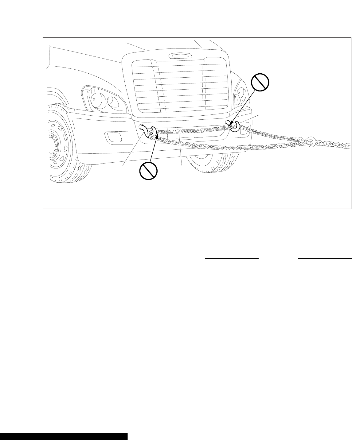
kph) is necessary, prepare the side extenders as
follows:
•If middle brackets are installed on the side
extenders, as shown in Fig. 24.7, remove
the rubber flex extenders.
•If middle brackets are not installed on the
side extenders, remove the side extenders
from the cab.
2. If the vehicle is equipped with cab air suspen-
sion, and reverse towing at speeds above 45
mph (70 kph) is necessary, hold down the cab as
follows:
2.1 Drain the air from the cab air springs.
2.2 Loop a 2-inch (5-cm) ratchet-style tension
strap (rated 2000 lb [900 kg] minimum
work load) over the top of the cab shock
and under the frame rail. See Fig. 24.8.
Tighten the strap for a snug fit. If the cab
is equipped with two or more shocks, re-
strain the aftmost shock on each side of
the vehicle.
3. Place the front tires straight forward and secure
the steering wheel in this position.
4. Disconnect the battery ground cables.
NOTICE
Failure to protect the frame rails from the chains
could cause damage, leading to eventual frame
failure.
5. On dual drive axles, using protection to keep the
chains from damaging the vehicle frame, chain
the forward-rear drive axle to the frame.
6. Attach the towing device.
NOTE: Due to the many variables that exist in
towing, positioning the lifting and towing device
is the sole responsibility of the towing-vehicle
operator.
7. Lift the vehicle and secure the safety chains. If
extra clearance is needed, remove the bumper
extension if equipped.
07/05/2007
OK
OK
1
1
2
f880793
IMPORTANT: Do not reeve when towing.
1. Tow Hook 2. Chain
Fig. 24.6, Reeving
In an Emergency
24.6
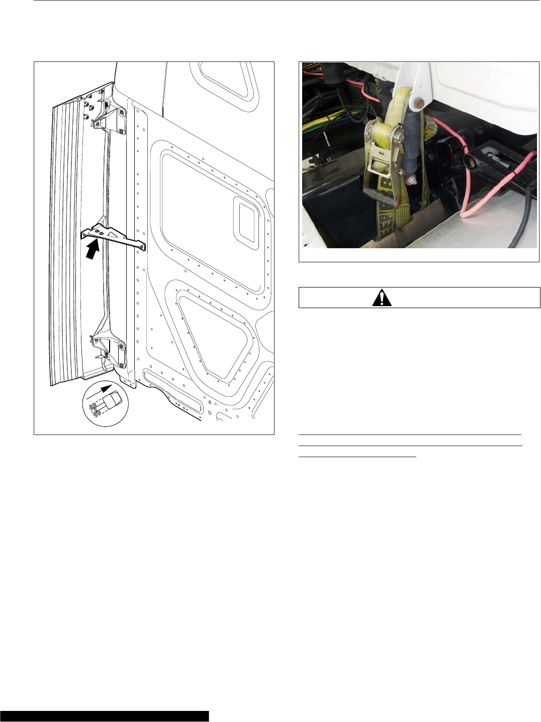
8. Connect the clearance lights, taillights, and sig-
nal lights. Also connect any special towing lights
required by local regulations.
Fire in the Cab
The incidence of fire in heavy- and medium-duty
trucks is rare, according to data from the National
Highway Traffic Safety Administration. Federal Motor
Vehicle Safety Standard #302 limits the flammability
of specified materials used inside the cab, but de-
spite this, most materials will burn. The cab of this
vehicle contains urethane foam, which is of concern
in this respect.
WARNING
Urethane foam is flammable! Do not allow any
flames, sparks, or other heat sources such as
cigarettes or light bulbs to contact urethane
foam. Urethane foam in contact with such heat
sources could cause a serious, rapid fire, which
could result in death, severe burns, or gas poi-
soning, as well as damage to the vehicle.
In Case of a Cab Fire
As quickly as possible, bring the vehicle to a safe
stop, apply the parking brake, turn off the ignition,
and get out of the vehicle.
01/05/2010 f602410
Fig. 24.7, Side Extender Middle Bracket
05/13/2014 f602527
Fig. 24.8, Tension Strap Installed to Hold Down the Cab
In an Emergency
24.7

25
Natural Gas Vehicles
Natural Gas Vehicles, General Information ............................................ 25.1
Natural Gas Vehicles, Safety Precautions ............................................ 25.1
Natural Gas Fuel Tank Filling Procedures ............................................. 25.3
Natural Gas Detection System ..................................................... 25.5
Natural Gas Engine Starting ....................................................... 25.9
Major Repairs and Replacement of Natural Gas Components ........................... 25.10

Natural Gas Vehicles, General
Information
The vehicle can be equipped with a compressed
natural gas (CNG) fuel system, or a liquefied natural
gas (LNG) fuel system. CNG is made by compress-
ing natural gas to less than 1% of its volume at stan-
dard atmospheric pressure. LNG is created by con-
densing natural gas into a liquid by cooling it to
approximately -259°F (-162°C).
When vaporized at ambient temperatures, natural
gas is less dense than air, and it rises and disperses.
However, LNG is initially heavier than air due to its
cryogenic temperature. When released in large
amounts, it may drop or pool on the ground before
its temperature rises enough to vaporize. Cold at-
mospheric conditions may prevent natural gas from
dispersing quickly when released in large amounts.
Natural gas is nontoxic, but it can cause asphyxiation
if present in very large concentrations.
CNG often contains an odor-producing chemical,
while LNG does not have any odor. Users of natural-
gas-fueled vehicles should never expect to detect
natural gas leaks by scent.
For natural gas to burn, it must first vaporize, then
mix with air in the proper proportions (flammable
range is 5 to 15% by volume in air), and then be
ignited.
A typical natural gas fuel system consists of:
•Fuel supply cylinders that store compressed
gas at high pressure (CNG), or a tank that
stores liquefied gas at an extremely low tem-
perature (LNG).
•A vaporizer or heat exchanging device that
changes LNG to gaseous form (LNG fuel sys-
tems only).
•Pressure relief and manual fuel shutoff valves.
•A filling connection with a check valve that pre-
vents the gas from flowing back out of the fuel
filling line.
•High-pressure and low-pressure fuel filters.
•A pressure control regulator that reduces the
high fuel tank or cylinder pressure to the lower
pressure needed for the engine.
•A fuel contents gauge that indicates the fuel
supply in the tank or cylinders.
Figure 25.1 shows the locations of various compo-
nents of a CNG installation.
Natural Gas Vehicles, Safety
Precautions
DANGER
Natural gas is highly flammable. Failure to ob-
serve the following safety precautions could lead
to the ignition of the natural gas, which could
cause serious bodily injury or death.
CNG systems should be maintained and inspected
exclusively by trained personnel with certifications in
accordance with the applicable codes. As with all
pressure vessels, CNG storage and fuel delivery sys-
tems are inherently dangerous and should be treated
as such. Individuals involved in any aspect of CNG
fuel system maintenance, emergency response, ser-
vicing, or testing must be properly trained and certi-
fied. Individuals who are not trained and certified in
all aspects concerning CNG fuel delivery systems
are not permitted to service, maintain, test, or inspect
a system in any way.
Follow these safety precautions when operating or
repairing a natural gas vehicle.
•Only certified LNG personal can fuel LNG
trucks.
•Do not start the engine if a natural gas leak is
detected.
•Transferring fuel is only allowed as long as a
non-static hose is used. if a non-approved
hose is used, static can build up and ignite the
fuel. A correct hose can be obtained through
Agility fuel systems.
•Do not attempt to cut any fuel supply piping
components.
•Avoid open flames or sparks near a natural
gas vehicle.
•Cover eyes and exposed skin when working on
a natural gas fuel system or fueling a natural
gas vehicle.
Natural Gas Vehicles
25.1
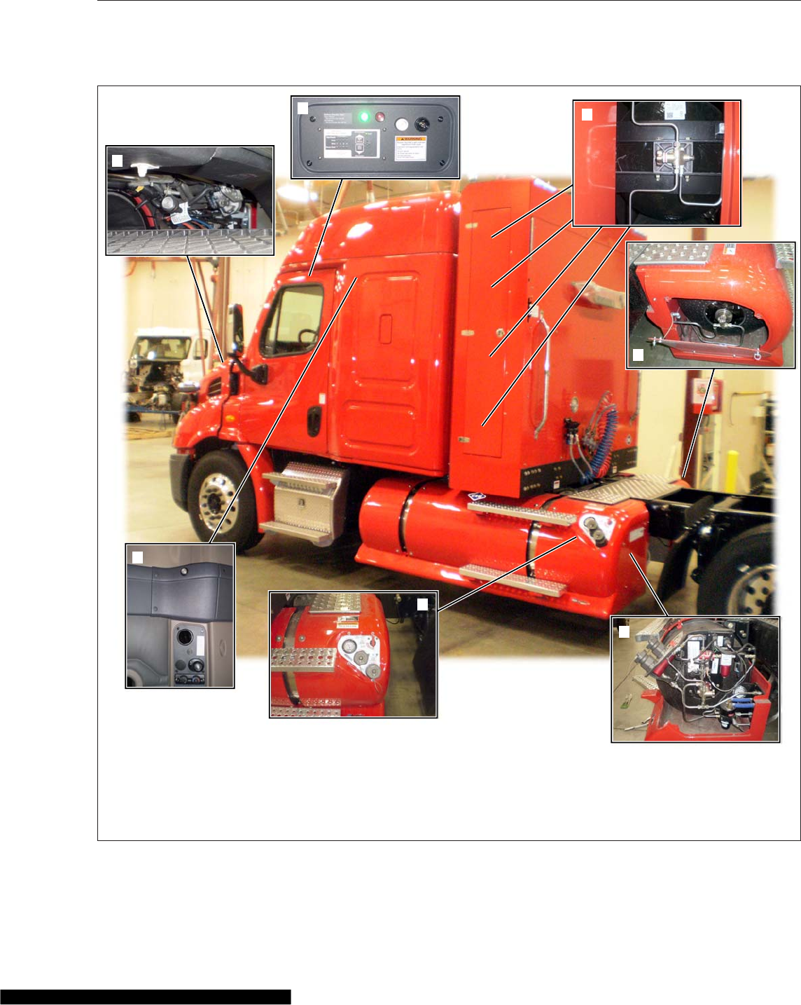
1
2
34
5
6
7
01/21/2014 f470613
1. Sleeper Leak Sensor (zone 3)
2. Engine Compartment Leak Sensor (zone 2)
3. Leak Detection Control Panel (zone 1) (overhead
console)
4. Cylinder Shutoff Valve (back-of-cab box)
5. Shutoff Valve, Right Side Cylinder
6. Shutoff Valve and System Components, Left Side
Cylinder
7. Fill Panel
Fig. 25.1, CNG Component Locations
Natural Gas Vehicles
25.2

•Permit no smoking or other ignition sources in,
or within thirty feet of, a natural gas vehicle.
•Have CO
2
fire extinguishers (ABC minimum)
located in a highly visible and easily accessible
location.
•Use Purple-K powder (PKP) or a similar dry
powder to extinguish an LNG fire. Do not at-
tempt use water around an LNG fire.
•Always purge the fuel lines before performing
maintenance or repairs on a natural gas fuel
system. Refer to the system manufacturer’s
service manual or the vehicle’s workshop
manuals for the proper purging procedure.
•Always use a natural gas detector to test the
system for leaks, whether an odor is present or
not. Routinely inspect the fuel filtering and
regulating mechanisms, and the fuel lines. An
approved natural gas bubble solution can be
used to pinpoint the exact location of leaks. Do
not use soap and water. Soap and water can
cause premature failure of the O-rings in the
system.
•Make sure black caps are always on the PRD
vent lines to reduce water build up in lines.
•Do not store a natural gas vehicle indoors for
any extended period of time. Do not bring a
natural gas vehicle indoors unless the work-
shop is equipped with a methane detection and
ventilation system.
In Case of Emergency
If a vehicle has sustained damage or a leak has
been discovered:
1. Turn the ignition switch off, and set the parking
brake.
2. Exit the vehicle leaving as many doors and win-
dows open as possible. Get at least 30 feet from
the vehicle, and allow it to vent until it is safe to
do the steps below.
3. Remove all ignition sources from the area sur-
rounding the vehicle.
4. If it is safe to do so, close all fuel shutoff valves.
5. Use a natural gas detector, or approved NG
bubble solution, to identify leaks in the fuel sys-
tem.
Natural Gas Fuel Tank Filling
Procedures
CNG Vehicle Fueling
CNG is moved from the fuel station storage tanks to
the vehicle cylinders through a metered dispenser.
During fueling, as pressure inside of the vehicle cyl-
inders increases, so does the temperature. The dis-
penser shuts off when it determines the CNG cylin-
ders are full.
CNG fuel cylinders cannot be filled to their full capac-
ity of 3600 psi (24 800 kPa) in cooler weather. Since
temperature change causes gas to expand and con-
tract, less pressure in the cylinders on a cold day is
equal to the same amount of gas at a higher pres-
sure on a warm day. The fuel station dispenser has a
temperature-pressure compensating device, which
accounts for ambient temperature during fueling. See
Table 25.1 for approximate full cylinder pressures at
various temperatures.
CNG Temperature/Pressure Compensation Values
Temperature:
°F (°C)
Fill Station Pressure Set Point
3000 psi (20 684
kPa) Set Point
3600 psi (24 821
kPa) Set Point
100 (37.8) 3415 (23 546) 4086 (28 172)
90 (32.2) 3276 (22 587) 3909 (26 952)
80 (26.7) 3138 (21 636) 3754 (25 883)
70 (21.1) 3000 (20 684) 3600 (24 821)
60 (15.6) 2861 (19 726) 3445 (23 752)
50 (10) 2723 (18 774) 3288 (22 670)
40 (4.4) 2584 (17 816) 3131 (21 587)
30 (-1.1) 2446 (16 865) 2973 (20 498)
20 (-6.7) 2307 (15 906) 2814 (19 402)
10 (-12.2) 2169 (14 955) 2655 (18 306)
0 (-17.8) 2031 (14 003) 2495 (17 202)
-10 (-23.3) 1893 (13 052) 2336 (16 106)
-20 (-28.9) 1755 (12 100) 2180 (15 031)
-30 (34.4) 1616 (11 142) 2024 (13 955)
-40 (-40) 1477 (10 184) 1868 (12 879)
Table 25.1, CNG Temperature/Pressure Compensation
Values
Use the following steps to fuel a CNG vehicle.
1. Shut down the engine and apply the parking
brake.
Natural Gas Vehicles
25.3
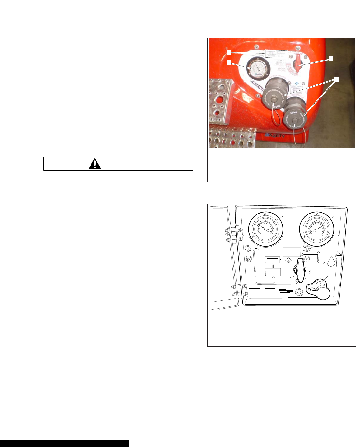
IMPORTANT: Close all windows and doors dur-
ing the fueling process. Keeping windows and
doors closed allows for easier leak detection
inside the cab after fueling.
NOTE: If the fuel system has only back of cab
tanks, the fuel fill is located behind the fuel ac-
cess panel on the lower part of the cabinet, or
below the tank cabinet in a separate box. If
truck has saddle mount tanks, the fuel panel is
located on the back end of the left side tank.
Vehicles with back-of-cab cabinets and saddle
tanks are have the fuel fill panel on the back
end of the left side tank. See Fig. 25.2 for side
tanks, or Fig. 25.3 for back-of-cab cabinet
mounted fuel panel.
WARNING
Natural gas fuel tanks, lines, and valves are al-
ways pressurized. Always observe safety precau-
tions. Failure to do so could lead to loss of con-
trol over a filling hose or to ignition of the natural
gas, which could cause serious bodily injury,
death, or severe property damage.
2. Ensure all fuel cylinder shutoff valves are open.
See Fig. 25.2.
3. Ensure the vehicle fuel system main shutoff
valve is open.
4. If equipped, open the CNG fuel panel access
door and remove the dust cap from the vehicle
fuel fill port.
5. Ensure the O-ring is present inside the fuel fill
port. If the O-ring has been dislodged or is miss-
ing, the station dispensing nozzle will not con-
nect securely to the fill port.
6. Turn the selector knob on the service pump to
the VENT position, if equipped.
7. Connect the quick coupling on the dispensing
nozzle securely to the vehicle fuel fill port.
8. Turn the selector knob on the service pump to
the FILL position, if equipped.
IMPORTANT: If at any time the service pump or
vehicle begins to vent CNG uncontrollably, notify
a station attendant or activate the service sta-
tion emergency shut-off switch to cease the flow
of CNG.
01/21/2014 f470615
2
13
4
1. High-Pressure Gauge
2. Fuel Cylinder Information Sticker
3. Manual Shutoff Valve
4. Fuel Fill Port
Fig. 25.2, CNG Fuel Cylinder Fill Panel (side tank
shown)
H
IGH
PR
ESS
UR
E
PR
ESS
UR
E
LOW
CYLINDERS
INSPECT CYLINDERS
EVERY 36 MONTHS
OR 36000 MILES
WHICHEVER OCCURS FIRST
NATURAL
GAS
VEHICLE
110 PSIG
ON
MANUAL
SHUT OFF
VALVE
OPEN VALVE
SLOWLY
3600 PSIG MAX.
SERVICE PRESSURE
REGULATOR
FILTER
INSPECT PRESSURE
RELIEF DEVICE
EVERY 2000 MILES
DRAIN HOUSING
EVERY 1500 MILES
REPLACE ELEMENT
EVERY 3000 MILES
12
3
4
04/30/2010 f470556
1. High Pressure Gauge
2. Low Pressure Gauge
3. Manual Fuel Shutoff Valve
4. Fuel Fill Port and Dust Cap
Fig. 25.3, CNG Under Cabinet Fuel Panel (under
cabinet shown)
Natural Gas Vehicles
25.4

9. Switch on the service pump. A slight hissing
noise may be heard as the fuel cylinders fill.
10. Watch the pressure gauge on the service pump.
When the gauge reads approximately 3600 psi
(24 800 kPa), or when the fill pressure stops
climbing, the CNG cylinders are full. The service
pump will shut itself down automatically. See
Table 25.1 for pressure compensation values
based on ambient temperatures.
11. Move the selector knob on the service pump to
the VENT position, if equipped. A short hiss will
be heard as a small amount of natural gas is
vented into the hose.
WARNING
Do not attempt to remove the fill station nozzle
from the tank fill fitting until venting of pressure
is noted. If no venting occurs, ask for assistance
from the station attendant. Removing an un-
vented coupling could result in an uncontrolled
hose, which could lead to property damage or
personal injury.
12. Remove the station dispensing nozzle from the
vehicle fill port.
NOTE: Some fill ports and dust caps contain a
magnetic start interrupt sensor to prevent a
truck from being started and driven away with
the fill hose connected. These caps must be
installed correctly or vehicle will not start.
13. Install the dust cap on the vehicle fuel fill port
and close the fuel panel access door, if
equipped.
LNG Vehicle Fueling
Only certified LNG fueling personnel are authorized
to fuel an LNG vehicle.
Natural Gas Detection System
A gas detection system is standard in all Daimler
Trucks natural-gas-fueled vehicles. This system has
a sensor in the engine compartment, one in the cab,
and one in the sleeper (if equipped), all situated in
high areas to detect natural gas buildup as a result
of leaks.
The AMGaDS III Plus is a natural gas detection sys-
tem. This device is meant to serve as a supplemen-
tal warning only. It is not intended to replace stan-
dard safety practices that should be conducted
around flammable gases.
IMPORTANT: To function properly, the gas de-
tection system must be powered at all times.
The gas detection system is directly powered by
the batteries, and can only be powered off by
disconnecting the batteries. When servicing a
natural-gas-fueled vehicle, disconnect the bat-
teries only when necessary, and do not leave
the batteries disconnected for extended periods
of time.
The lower flammability limit (LFL) is the smallest
amount of the gas that supports a flame when mixed
with oxygen and ignited. Zero percent (0%) LFL indi-
cates a gas-free atmosphere. One hundred percent
(100%) LFL indicates that gas concentration has
reached its lower flammability limit (5% gas in air by
volume). The red warning light and audible alarm
located in the overhead console activate when a sen-
sor detects gas fumes in concentrations above 50%
LFL, and should allow ample time to utilize safety
procedures. However, individuals with special needs
should review the system with a professional safety
engineer.
Alarm Procedure
Before operating the vehicle, the driver must be fa-
miliar with the procedures as shown on the interior
sticker on the overhead panel (See Fig. 25.4) and
the exterior sticker on the door (See Fig. 25.5).
IMPORTANT: If an audible alarm activates, do
not operate any electrical switch, including
lights. Avoid causing sparks and stay away from
arcing switches and equipment. Do not use a
telephone, including cellular phones or any
types of portable communication or electronic
devices that have a battery.
If the vehicle is in motion when the audible alarm
activates, bring it to a safe stop, shut down the en-
gine, and exit the vehicle. Do not open the hood.
If outside the vehicle when the audible alarm acti-
vates, do not open the cab door or hood.
In the event of an audible alarm, immediately follow
these procedures, as allowed by conditions:
Natural Gas Vehicles
25.5
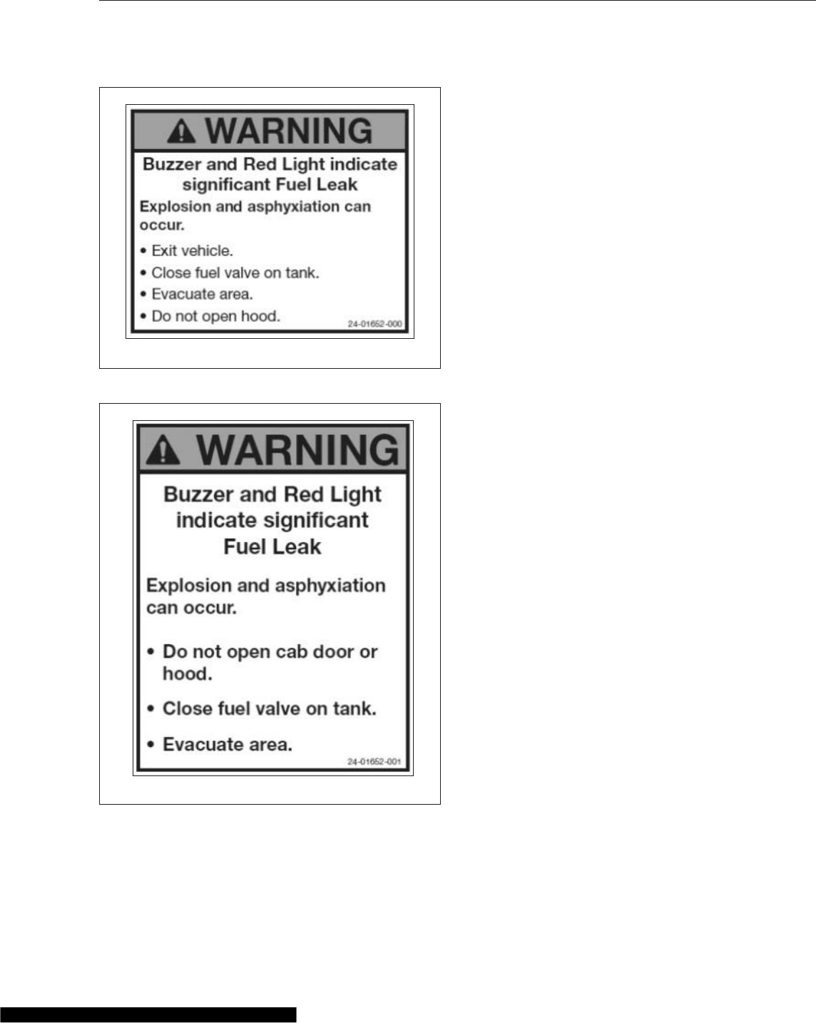
1. Immediately shut off all engines. Extinguish any
cigarettes, pilot lights, flames, or other sources of
ignition in the area and adjacent areas.
2. Exit the vehicle leaving as many doors and win-
dows open as possible, and move at least 30
feet away from vehicle. If the vehicle is parked,
stay at lease 30 feet away until it is safe to do
the following.
3. Manually close all fuel shutoff valves, including
those on the LNG tank or CNG cylinders.
4. If the vehicle is indoors (as in a service shop),
immediately open shop windows and doors to
provide extra ventilation to the area. Do not start
the engine or any other type of equipment until
the gas leak is corrected and the area cleared of
natural gas.
5. Evacuate the area.
6. After the area is cleared of natural gas and the
alarm is no longer active, have the vehicle in-
spected by a qualified technician.
IMPORTANT: Do not consider the area clear
until all alarm indicators are off, and the alarm
panel light returns to green.
Sensors
Gas detection sensors are located on the cab over-
head console (zone 1), in the engine compartment
on the frontwall (zone 2), and in the sleeper, if
equipped (zone 3). The sensors are located in high
areas, where rising gas vapors will pass by or accu-
mulate. On some vehicles, there is a sensor located
under the cab floor (zone 4). Zone 4 is not used on
DTNA vehicles.
If the system detects that one of the sensors has
been disconnected or has malfunctioned, the sensor
fault light for that zone will illuminate. A failed sensor
may trigger and lock on an alarm. If this happens
have a qualified technician troubleshoot the system
and make appropriate repairs.
The sensors are sensitive to all hydrocarbon vapors.
An alarm may be triggered by the use of chemicals
such as cleaners, paint, polish, lacquer, gasoline,
silicone, silicone spray, or other harsh chemicals.
The sensors will also detect hydrogen fumes from an
overcharged battery. If a sensor sends an alarm, but
no gas fumes are present, check for recent use of
chemicals or a battery charger.
04/28/2009 f080157
Fig. 25.4, Interior Warning Sticker
04/28/2009 f080158
Fig. 25.5, Exterior Warning Sticker
Natural Gas Vehicles
25.6

NOTICE
Silicone-based chemicals and cleaners will per-
manently disable the sensors. When cleaning the
vehicle, cover the sensors with a plastic cover-
ing. Keep the sensors covered until the area has
been cleared of any cleaning fumes.
Harsh chemicals, including some high alcohol
cotenant washer fluids, and extremely high tem-
peratures may damage the sensor.
Puncture of or damage to the seal located inside
the sensor housing will significantly shorten the
sensor life.
Frequent exposure to high concentrations of gas
will accelerate sensor deterioration.
Overhead Console
The overhead console consists of an alarm panel on
the right side and the control module on the left side.
The alarm panel has a green light, a red light, a
buzzer, and a sensor. See Fig. 25.6. It is located
within view from outside of the vehicle. The large
green light is continuously illuminated during normal
operating conditions.
Before entering the vehicle, always verify that the
green light is illuminated. If the green light is not illu-
minated, do not enter the vehicle. Complete the
alarm procedure previously outlined.
The alarm panel meets the California Highway Patrol
Title 13-2008 and NFPA 52 2010 requirements. All
drivers and technicians using it should be trained re-
garding the red and green lights, and the audible
warning.
The control module, located on the center of the
overhead console, contains the status lights and con-
trol buttons for the system. The areas that the sen-
sors monitor are defined as Zone 1 (cab), Zone 2
(engine compartment), and Zone 3 (sleeper, if
equipped). The control module has lights assigned to
each zone that will illuminate if a sensor detects a
trace level leak (between 20% and 30% LFL), a sig-
nificant level leak (above 50% LFL), or if a sensor is
disconnected or malfunctioning.
•Trace Level: If either sensor detects gas fumes
at a concentration greater than 20% to 30%
LFL (1% gas in air by volume), the amber light
next to the Trace indicator for that zone will
flash. There is no buzzer alarm for a trace
level detection, and the large green light on the
alarm panel will remain illuminated.
•Significant Level: If either sensor detects gas
fumes at a concentration greater than 50% to
60% LFL (2.5% gas in air by volume), the
small red light next to the SIGNIFICANT indi-
cator for that zone will flash. After approxi-
mately 15 seconds, the large green light on the
alarm panel will switch off, the red light will illu-
minate, and the buzzer will sound. All alarm
indicators will remain on as long as fumes are
detected.
•Sensor Fault: If the system detects that either
of the sensors has been disconnected or has
malfunctioned, an amber light next to the Sen-
sor Fault indicator for that zone will illuminate.
The control module also has buttons used to test or
reset the the control module after an alarm. Red
lights next to each button indicate when they are en-
gaged.
•Shutdown Reset: If an alarm has been acti-
vated and the Relay Engaged light is illumi-
nated, the Shutdown Reset button will reset
the internal relay. Press the Shutdown Reset
button only after the gas has cleared, the
buzzer has turned off, and the alarm panel
light has returned to green.
•Push To Silence: If an alarm has been acti-
vated, the Push To Silence button will silence
the buzzer.
See Table 25.2 for the functions of all lights and but-
tons on the overhead console.
Testing
Daimler Trucks North America strongly recommends
that all operators follow California Code of Regula-
tions (CCR) inspection requirements, regardless of
where the vehicle is operated. Per Title 13 CCR §
935 (2), gas detection systems should be tested
three times per calendar year at equal intervals. The
testing procedure should simulate the same operat-
ing environment in which the vehicle is used, with the
same gaseous fuel.
Natural Gas Vehicles
25.7
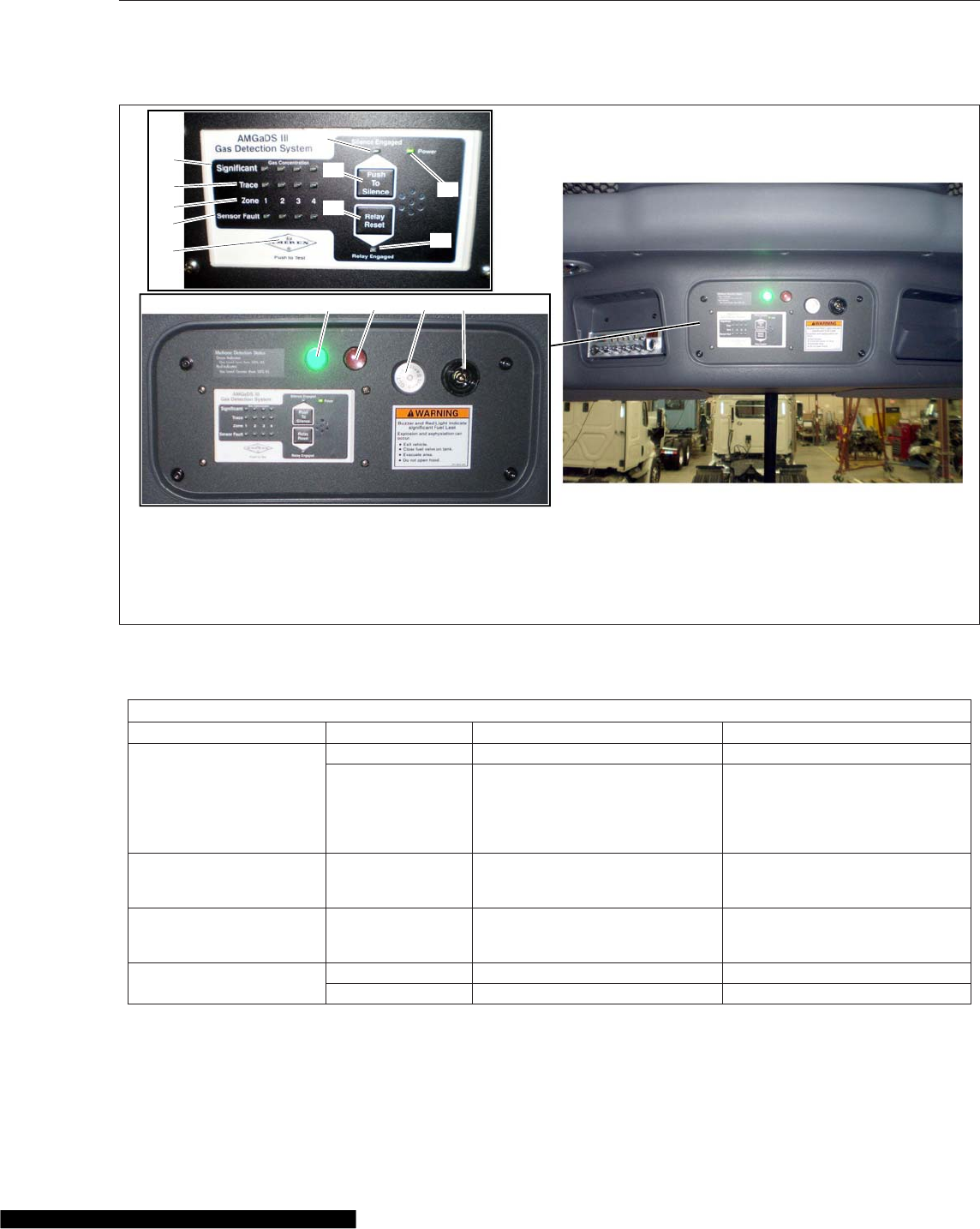
Control Module Functions
Item Display Function Action Required
Green Power Light
Illuminated System is on. None required.
Unlit Detection system is not
functioning.
Ensure the batteries are
connected and replace any blown
fuses. If the gas detection system
is still not functioning, replace the
system immediately.
SIGNIFICANT Gas
Concentration Lights Red (illuminated) Dangerous gas concentration
detected.
Suspend vehicle operation
immediately and follow alarm
procedures.
Trace Gas Concentration
Lights Amber (flashing) Minor gas concentration detected.
Suspend vehicle operation
immediately and follow alarm
procedures.
Sensor Fault Lights Off Sensor is functioning properly. None required.
On Sensor has malfunctioned. Replace the sensor immediately.
02/06/2014 f470614
13 42
10
11
12
14
13
9
5
6
7
8
1. Green Light
2. Red Light
3. Sensor
4. Buzzer Alarm
5. Test Button
6. Sensor Fault Indicator Lights
7. Zone Numbers
8. Trace Leak Indicator Lights
9. Significant Leak Indicator Lights
10. Silence Engaged Light
11 Silence Button
12. Relay Reset Button
13. Relay Engaged Light
14. Power Indicator Light
Fig. 25.6, AMGaDS III Overhead Console
Natural Gas Vehicles
25.8

Control Module Functions
Item Display Function Action Required
Shutdown Reset Button — Resets the system after an alarm
activation.
Press to reset the system only
after the gas has cleared, the
buzzer has turned off, and the
alarm panel light has returned to
green.
Relay Engaged Light On Relay is engaged and test or
alarm is being cleared. Press the Shutdown Reset button.
Off Normal condition. None required.
Test Button — Tests the overhead console
operation and circuitry.
Press and hold for one minute to
to activate a test of all overhead
console components.
Silence Button — Silences the alarm buzzer. Press to silence the alarm buzzer.
Silence Engaged Light On Indicates the buzzer is active but
silenced.
Suspend vehicle operation
immediately and follow alarm
procedures.
Off Normal condition. None required.
Table 25.2, Control Module Functions
Test results validating the performance of the gas
detection system within the parameters established
by the component manufacturer and NFPA 52 2010
should be maintained as a permanent part of the ve-
hicle service records. Use of alcohol, propane, and
other harsh liquids or gases are not acceptable
methods for testing.
Always test the system and sensors after any com-
ponent has been replaced, or if the vehicle has been
involved in an accident or fire. Ensure that the gas
detection system is wired directly to the battery.
It is recommended that the highest level of safety
validation be utilized if there are multiple validation
requirements in the state or locality where the vehicle
is operated or domiciled.
Overhead Console Test
Press and hold the Push To Test button for one min-
ute. The system will proceed with a self-diagnostic
test that will include illumination of the Trace and Sig-
nificant gas concentration lights, and the sensor fault
lights. Verify the large red light and buzzer activate,
and that all lights illuminate or flash to ensure that all
bulbs are operational.
Sensor Test
The gas detection system sensors must be tested
using qualified test gas, which can be purchased as
part of a test kit. Testing with alcohol or heavy gases
such as butane or propane does not satisfy CCR §
935 (2) or NFPA 52 regulations.
Expose each sensor to qualified test gas for at least
30 seconds. The system will proceed through the
alarm procedure consistent with a significant leak
and the buzzer will sound after approximately 15
seconds. If a sensor fails to respond after exposure
to the test gas, replace the sensor.
Natural Gas Engine Starting
NOTE: Before starting the engine, read Chap-
ter 4 for detailed information on how to read the
instruments and Chapter 5 for detailed informa-
tion on how to operate the controls. Read the
operating instructions in the engine manufactur-
er’s operation manual before starting the en-
gine.
1. Before engine start-up, complete the engine pre-
trip and post-trip inspections and maintenance
procedures in Chapter 21.
2. Ensure the fuel shutoff valve is open.
3. Set the parking brake.
4. Ensure that the transmission shift control is in
Neutral (N), Park (P), or the Park Brake (PB) po-
sition.
Natural Gas Vehicles
25.9
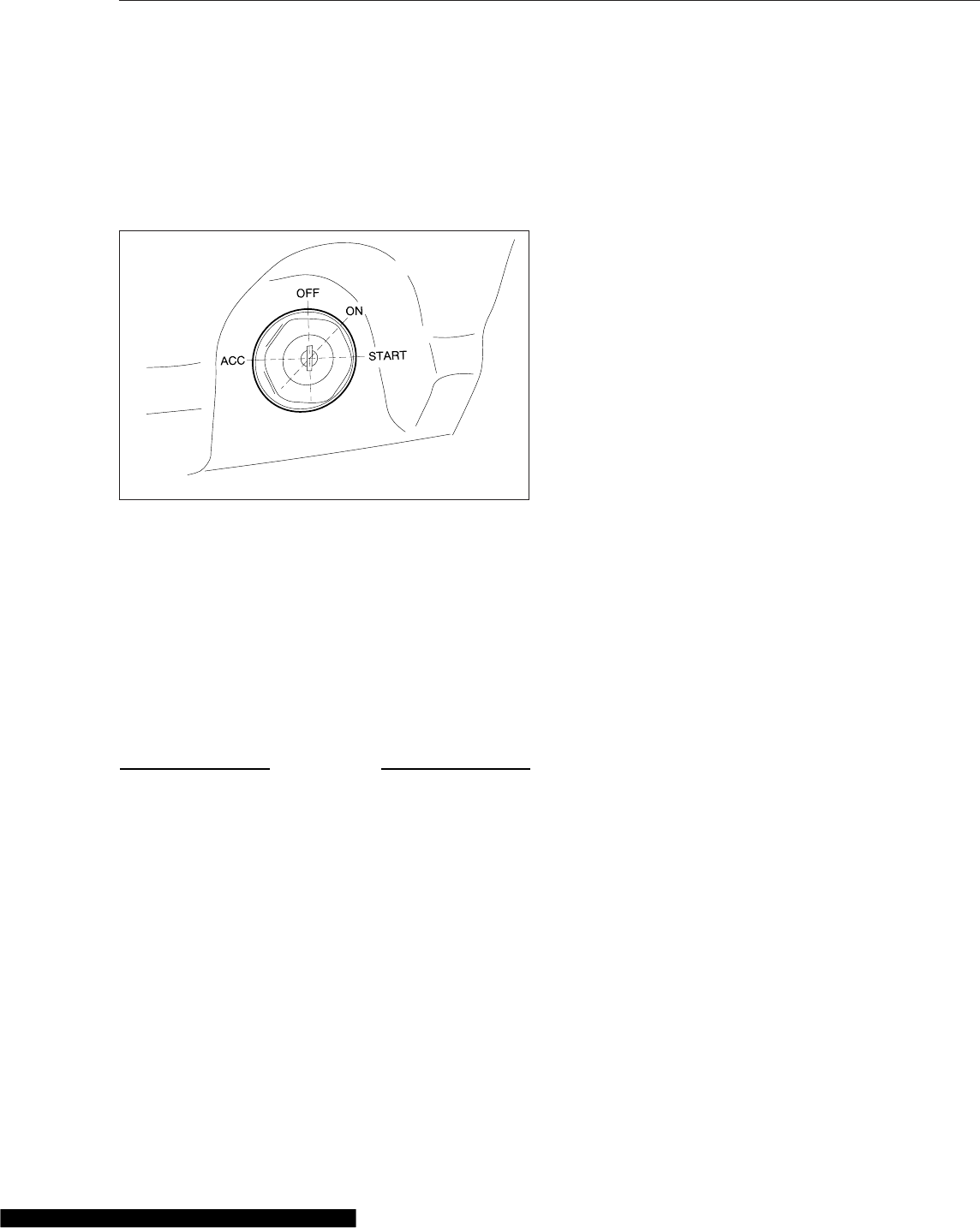
5. Without starting the engine, turn the ignition
switch to the ON position (Fig. 25.7). The elec-
tronic gauges on the instrumentation control unit
(ICU) will complete a full sweep of their dials, the
warning and indicator lights will illuminate, and
the buzzer will sound for three seconds.
6. Turn the ignition switch to the START position.
Press down on the clutch pedal, if equipped, but
do not press down on the accelerator pedal.
Release the key the moment the engine starts.
7. Bring the engine up to operating speed gradually
as it warms up and develops stable oil pressure.
If the vehicle has not been operated previously in
a 24-hour period, allow the vehicle to idle for five
minutes.
NOTICE
Do not rev the engine if the oil pressure gauge
indicates no oil pressure. Shut down the engine
within approximately ten seconds to avoid engine
damage.
8. Check the oil pressure gauge for any drop in lu-
bricating oil pressure or mechanical malfunction
in the lubricating oil system.
Major Repairs and
Replacement of Natural Gas
Components
IMPORTANT: All repairs to natural gas system
and components must be performed by certified
technicians.
If a natural-gas-fueled vehicle is involved in an acci-
dent, remove the fuel tank or cylinders from service
and have them inspected by a qualified technician.
Replace any leaking or damaged fuel tanks/cylinders
and fuel lines; repair or replace leaking or damaged
fittings. Install parts and components in accordance
with the manufacturer’s instructions.
07/19/2006 f610805
Fig. 25.7, Ignition Switch Positions
Natural Gas Vehicles
25.10

26
Specifications
Fuses and Relays ................................................................ 26.1
Replacement Bulbs .............................................................. 26.3
Fluids and Lubricants ............................................................. 26.4

Fuses and Relays
CAUTION
This vehicle may be equipped with a roof-
mounted Citizens’ Band (CB) antenna. Operation
of an amplified CB radio with output power
greater than FCC limits (4W AM/12W SSB) is ille-
gal, and may expose vehicle occupants to radio
frequency (RF) radiation that exceeds FCC maxi-
mum permissible RF exposure limits. Vehicle oc-
cupants with electronic medical devices should
consult the device manufacturer’s user manual or
a physician for information on RF radiation expo-
sure limit guidelines.
SAM Cab Fuses
Part Name AMP
F1 Power FD Spare1&3 30
F2 Cab/Slpr HVAC Ctrl
Trans Shift Pnl 15
F3 Power FD Spare2&4 30
F4 MSF 15
F5 OBD J1939
OBD DCDI 10
F6 Dash Power Recp 1 15
F7 Dash Power Recp 2 15
F8 Phone/Radio 15
F9 Amplifier Power 20
F10 Cab HVAC Motor 30
F11 Sleeper HVAC Motor 30
F12 Door Controls, L 20
F13 Door Lock
Coll Warn Sys 20
F14 Fleet Mgm Sys
CB 25
F15 Sleeper Power Recp 3 20
F16A Aux Cab Heater Enable 3
F16B Aux Coolant Heater 20
F17 Power Recp 4 20
F18
GPS
Tire Press Monitor
Antitheft Warn
AuxiliaryTelematics
15
F19 Heated Seat 20
SAM Cab Fuses
Part Name AMP
F20 CGW 2
F21 Area Light 15
F22 ICU
Horn Switch 5
F23
GPS
Driver Info Sys
Fleet Mgmt Sys
Pyrometer, Axle Temp, Eng
Oil Temp Gauges
15
F24 Diagnostic Conn
ICU 7.5*
F25
Trans Temp Gauge/Shift
Select
Phone
Collision Warn Sys
10†
F26 SRS Airbags 5
F27 Mirror Heat, L 10
F28 Mirror Heat, R 10
F29 SAM Relay Coils 3
F30 Power Recp 6 20
F31 Power Recp 5 20
F32 Power FD Spare 5 & 6 25
F33 Spotlight 20
F34 Baggage Comp Lamp 3
F35 Dome Lamp 15
F36 Aux Circulation Fan
Road Lamps 15
F37
Clock (cab & sleeper)
Driver Info Sys
CD Player
Keyless Entry
15
F38 Door Controls, R 20
F39 Power Window, R 15
F40 Power Window, L 15
F41 Aux Mirror Heat 10
*F24 value on assemblies -005 and lower is 10 amps.
†F25 value on assemblies -005 and lower is 7.5 amps.
Table 26.1, SAM Cab Fuses
Specifications
26.1

SAM Cab Relays
Position Function Source
BR21 Power FD Spare1&3
Dash Power Recp 1 BAT
BR22 Power FD Spare2&4
Slpr Power Recp 3 BAT
R3 Heated Seats IGN
BR23
Dash Power Recp2
Fleet Mgmt Sys
CB
Aux Cab Heater
Aux Coolant Heater
BAT
R7
GPS
Driver Info Sys
Fleet Mgmt Sys
Pyrometer, Axle Temp, Eng
Oil Temp Gauges
IGN
R8
Diagnostic Conn
ICU
Trans Temp/Shift Select
Phone
Coll Warn Sys
SRS Airbags
IGN
R9 Amplifier Power ACC
R10 Mirror Heat (L, R, & Aux) ACC
BR24
Power Recp6
Area Lighting
Baggage Comp Lamp
Dome Lamp
BAT
BR25
PowerRecp4&5
Aux Circulation Fan
Reading Lamp
BAT
R15 Power Windows ACC
Table 26.2, SAM Cab Relays
SAM Chassis Fuses
Part Name AMP
F1 Elec Air Process. Unit
(EAPU) 20
F2 Fuel/Water Separator Heat 20
F3 ABS Bat 1 20
F4 ABS Bat 2 10
F5 Trailer Left-Turn Lamp 20
F6 ABS 15
F7 EAPU/WIF
Rear Camera 10
F8 Trailer Right-Turn Lamp 20
F9 Trailer Marker Lamps 30
F10 SAM Relay Coils 5
F11 Trailer ABS 30
F12 Trailer Stop Lamps 30
F13 Trailer Tail Lamps 20
F14 Trailer Power 30
Table 26.3, SAM Chassis Fuses
SAM Chassis Relays
Position Function
R1 Fuel/Water Separator Heat
R2 Trailer Left-Turn Lamp
R3
ABS
EAPU/WIM
Rear Camera
R4 Trailer Right-Turn Lamp
R5 Trailer Marker Lamps
R6 Trailer ABS
R7 Trailer Stop Lamps
R8 Trailer Power
R9 Trailer Tail Lamps
Table 26.4, SAM Chassis Relays
MEGA Fuse Junction Block (MFJB) Fuses, EPA07
Only
Part Name AMP
F1 Powertrain PDM 175
F2 SAM Cab 175
F3 SAM Chassis 125
F4 Chassis-Mounted Trailer
PDM 125
Specifications
26.2

MEGA Fuse Junction Block (MFJB) Fuses, EPA07
Only
Part Name AMP
F5 Inverter 200
Table 26.5, MEGA Fuse Junction Block (MFJB) Fuses,
EPA07 Only
Powernet Distribution Box (PNDB) Fuses, EPA10 and
Newer
Fuse Function AMP
AAftertreatment Control
Module 30
B Emergency Power 20
C Radio/Clock 5
D Alternator Remote Sense 5
1 Powertrain PDM 175
2 SAM Chassis 125
3 SAM Cab 175
Table 26.6, Powernet Distribution Box (PNDB) Fuses,
EPA10 and Newer
Trailer PDM Fuses and Relays
Position Function AMP
F1 Trailer Power Fuse 30
F2 Taillight Fuse 30
F3 Left-Turn Lamp Fuse 20
F4 Right-Turn Lamp Fuse 20
F5 Marker Lamp Fuse 30
F6 Stop Lamp Fuse 30
R1 Taillight Relay
R2 Right-Turn Relay
R3 Stop Lamp Relay
R4 Trailer Power Relay
R5 Left-Turn Relay
R6 Marker Lamp Relay
Table 26.7, Trailer PDM Fuses and Relays
Replacement Bulbs
Replacement Bulbs
Lamp Assembly Replacement Bulb
Headlight Hi/Low Beam, Fog
light, Driving Light
WEE 12362LLBA
(H11)
Turn/Marker Lamp (in headlight
assy) GE 3457
Incandescent Auxiliary Turn (on
fender) GE 2058U
Integral Stop/Tail/Backup Lights GE 1157/GE 1156
Utility Light WEE 199
Cab Dome Lamp, Clear,
Outboard GN12 BUL 050 R5WC
Cab Dome Lamp, Clear, Inboard GN12 BUL 049 R10W
Cab Dome Lamp (Red) GN12 BUL 050 R5WR
Sleeper Reading Lamp GRLSAP270
Sleeper Dome Lamp GRLBUL049R10W
Sleeper Writing Desk Lamp GRLBUL027578
Sleeper Bunk Lamp GRLBUL0142112
Footwell Lamp (Red) GRLBUL042W5W
Table 26.8, Replacement Bulbs
Specifications
26.3

Fluids and Lubricants
Type Approved Fluid or Lubricant
Engine Oil*Engines compliant with EPA07 or newer regulations: Engine lube oil with a sulfated ash level less
than 1.0 wt %; currently referred to as CJ-4 oil.
Fuel†Engines compliant with EPA07 or newer regulations: Ultralow-sulfur diesel (ULSD) with 15 ppm
sulfur content or less, based on ASTM D2622 test procedure.
Power Steering Fluid ATF must meet TES 389 or Dexron III specifications
Hydraulic Clutch Fluid DOT 4
Manual Transmission
Lubricant‡§
MobilTrans SHC 50 (RN 2952 E-5), SAE 50W
Synthetic transmission lubricant approved by Eaton, SAE 50W
Antifreeze
Caterpillar Diesel Engine Antifreeze/Coolant. Contains supplement additives. Available as a
premixed solution.
Detroit™Power Cool, premixed solution with supplement additives.
Old World Industries, Fleet Charge™, with supplement additives.
Drive Axle Lubricant
Recommended SAE Viscosity Grade Ambient Temperature Range
75W –40°F to –15°F (–40°C to –26°C)
75W—80 –40°F to 80°F (–40°C to 27°C)
75W—90 –40°F to 100°F (–40°C to 38°C)
75W—140 –40°F and above (–40°C and above)
80W—90 –15°F to 100°F (–26°C to 38°C)
80W—140 10°F and above (–12°C and above)
*See the engine manufacturer’s manual for specifications.
†See the engine manufacturer’s manual for specifications.
‡Do not mix types or brands of fluid. Multi-weight and extreme-pressure gear fluids are not recommended.
§Call 1-800-826-4357 for a complete list of Eaton approved lubricants.
Table 26.9, Approved Fluids and Lubricants
Specifications
26.4

Subject Page
A
Accessory Heaters ........................ 8.5
Espar Heater ......................... 8.6
Webasto Heater ....................... 8.7
Adjustable Steering Column
Controls ............................. 5.20
Adjusting Headlight Aim ................... 23.1
Air Brake System ........................ 13.1
Automatic Slack Adjusters ................ 13.3
Brake System Components ............... 13.1
Brake System General
Information ......................... 13.1
Brake System Operation ................. 13.1
Air-Suspension Dump Valve ................. 19.1
B
Back-of-Cab Access ....................... 2.4
Climbing Down from Back-
of-Cab ............................. 2.5
Entering Back-of-Cab .................... 2.5
C
Cab Amenities ........................... 9.1
Cup Holders .......................... 9.1
Lighting ............................. 9.1
Power Outlets ......................... 9.1
Radio and CB ......................... 9.2
Storage ............................. 9.2
Cab Climate Control Panel .................. 8.1
Fan Switch ........................... 8.1
Mode Control Switch .................... 8.2
Temperature Control Switch ................ 8.1
Cab Door Locks and Handles ................ 2.1
Cab Washing and Polishing ................. 22.1
Cab-to-Sleeper Access ..................... 2.3
Canadian Motor Vehicle Safety
Standard Labels ........................ 1.1
Care of Chrome Parts ..................... 22.1
Care of Exterior Lights .................... 22.1
Care of Fiberglass Parts ................... 22.1
Cascadia 2.0 High-Back Seat ................ 7.2
Armrest Angle ......................... 7.3
Bottom Cushion Extension ................ 7.3
Fore/Aft Isolator ........................ 7.2
Height Adjustment ...................... 7.2
Lumbar Support ....................... 7.2
Recline ............................. 7.2
Seat Fore/Aft Slide ...................... 7.3
Seat Heating/Ventilation .................. 7.2
Subject Page
Seat Tilt ............................. 7.3
Shock Absorber Adjustment ................ 7.2
Cascadia High-Back Seat ................... 7.3
Backrest Tilt .......................... 7.3
Bottom Cushion Extension ................ 7.3
Fore/Aft Isolator ........................ 7.3
Fore/Aft Seat Slide ...................... 7.3
Front Cushion Height .................... 7.3
Heater .............................. 7.4
Height Adjustment ...................... 7.3
Lumbar Support ....................... 7.3
Rear Cushion Height .................... 7.3
Shock Absorber ........................ 7.3
Checking Headlight Aim ................... 23.1
Checklists ............................. 20.1
Daily Pretrip Inspection
Checklists ......................... 20.1
Monthly Post-trip Inspection
Checklists ......................... 20.2
Weekly Post-trip Inspection
Checklist .......................... 20.2
Climate Controls ........................ 5.17
Cab Climate Control .................... 5.17
Sleeper Climate Control ................. 5.18
Clutch ............................... 14.5
Clutch Maintenance .................... 14.7
Clutch Operation ...................... 14.6
General Information .................... 14.5
Component GWR Label .................... 1.1
Component Information Label ................ 1.1
Cruise Control .......................... 5.11
Cruise Control ("CC") Limiter .............. 5.13
Descent Control and
Deceleration Modes,
Detroit™Automated
Transmissions ....................... 5.13
Run Smart Predictive
Cruise™........................... 5.12
D
Daily Pretrip Inspection and
Maintenance .......................... 21.1
Cab Inspection ....................... 21.5
Engine Compartment
Inspection ......................... 21.4
Natural Gas Fuel System
Inspection ......................... 21.8
Saddle Tank Areas
Inspection ......................... 21.4
Suspension and Slack
Adjuster Inspection ................... 21.1
Wheel and Tire Inspection ................ 21.2
Index
I-1

Subject Page
Dashboard Care ........................ 22.2
Dash-Mounted Brake Controls ............... 5.14
Antilock Braking System ................. 5.15
Parking Brake Control Valve ............... 5.14
Trailer Air Supply Valve .................. 5.14
Trailer Brake Lever ..................... 5.15
Detroit™Automated
Transmissions ......................... 15.1
Clutch Abuse Protection ................. 15.4
Creep Mode ......................... 15.3
Detroit™Multifunction
Control ........................... 15.1
Driving Modes ........................ 15.2
eCoast ............................. 15.3
Engine Overspeed Alerts ................. 15.4
Gear Display Window ................... 15.2
Low Transmission Air
Warning ........................... 15.4
Power Up and Shift into
Gear ............................. 15.2
Selected Gear ........................ 15.3
Suggested Shift ....................... 15.3
Diesel Exhaust Fluid and Tank,
EPA10 and Newer Engines ................ 12.3
DEF Tank ........................... 12.4
DEF Warnings and Engine
Limits ............................ 12.5
Diesel Exhaust Fluid .................... 12.3
Fuel/DEF Gauge ...................... 12.4
Differential Locks ........................ 16.1
Driver-Controlled Differential
Lock (DCDL) ........................ 16.1
Single Drive Axles with
Traction Equalizer .................... 16.2
Tandem Drive Axles with
Interaxle Differential Lock ............... 16.1
Driver Message Center .................... 4.11
ICU3/ICU4 .......................... 4.11
ICU4Me ............................ 4.19
ICU4M ............................. 4.13
E
Eaton Fuller 10-Speed Range-
Shift Transmissions ..................... 14.4
General Information, Eaton
Fuller Range-Shift .................... 14.4
Operation, Eaton Fuller
Range-Shift ........................ 14.4
Eaton Fuller 13-Speed and 18-
Speed Splitter and Range-
Shift Transmissions ..................... 14.1
Subject Page
General Information, Eaton
Fuller Splitter and Range-
Shift ............................. 14.1
Operation, Eaton Fuller
Splitter and Range-Shift ................ 14.1
Eaton Fuller AutoShift
Automated Transmissions ................ 15.11
General Information,
AutoShift .......................... 15.11
Operation, AutoShift with
SmartShift ......................... 15.11
Eaton Fuller UltraShift PLUS ............... 15.14
Auto Neutral ........................ 15.17
Auto Start Gear Selection
and Override ....................... 15.17
Automatic Mode (AUTO) ................ 15.14
Automatic Traction Control ............... 15.17
Clutch Abuse Protection ................ 15.15
Coasting ........................... 15.17
Creep Mode ........................ 15.16
Engine Overspeed
Protection ......................... 15.16
Hill Start Aid ........................ 15.16
Load-Based Shifting ................... 15.17
Low (L) ............................ 15.15
Manual Mode (MAN) ................... 15.15
Power Down ........................ 15.14
Power Up .......................... 15.14
Reverse (R) ......................... 15.14
Shuttle Shifting ...................... 15.16
Skip Shifting ........................ 15.17
Eaton Fuller UltraShift ..................... 15.6
General Information,
UltraShift DM ....................... 15.6
Operation, UltraShift DM ................. 15.6
Ultrashift Diagnostics .................. 15.10
Electrical Power Distribution .................. 3.1
Cab Load Disconnect Switch ............... 3.3
Circuit Protection Features ................ 3.1
MEGA Fuse Junction Block,
EPA07 ............................. 3.1
Power Distribution Modules ................ 3.1
Powernet Distribution Box,
EPA10 and Newer ..................... 3.1
Emergency Filter Replacement,
Davco .............................. 24.1
Emergency Kit, Optional ................... 24.1
Emergency Power Supply ................... 3.3
SAM Cab Fault ........................ 3.4
SAM Chassis Fault ..................... 3.4
Emergency Starting With
Jumper Cables ........................ 24.2
Emissions Labels ......................... 1.1
Index
I-2

Subject Page
Aftertreatment System
Indicators Label ...................... 1.1
Certified Clean Idle Label ................. 1.4
EPA Noise Emission Control
Label ............................. 1.3
Vehicle Emission Control
Information Label ..................... 1.4
Engine Brake .......................... 13.5
Engine Brake Operation ................. 13.5
Engine Idle Limiting ...................... 11.2
California Engine Idle
Limiting ........................... 11.2
Idle Shutdown Timer .................... 11.2
Engine Operation ........................ 10.2
Cold-Weather Operation ................. 10.3
Engine Break-In ....................... 10.3
High-Altitude Operation .................. 10.4
Normal Operation ...................... 10.3
Safety and Environmental
Considerations ...................... 10.2
Engine Protection—Warning
and Shutdown ......................... 11.1
Engine Shutdown ........................ 10.4
Engine Starting ......................... 10.1
Cold-Weather Starting ................... 10.2
Starting After Extended
Shutdown .......................... 10.2
Enhanced Stability Control .................. 6.13
EPA-Regulated Emissions
Aftertreatment Systems ................... 12.1
ATS Warning Lamps .................... 12.3
EPA07 Engines ....................... 12.1
EPA10 and Newer Engines ............... 12.1
Maintenance ......................... 12.3
Regeneration ........................ 12.2
F
Federal Motor Vehicle Safety
Standard Labels ........................ 1.1
Fifth Wheel Coupling ..................... 18.1
Fontaine and Holland Fifth
Wheels Coupling ..................... 18.1
Jost Fifth Wheel Coupling ................ 18.3
Fifth Wheel Slide ........................ 18.7
Air Slide Operation ..................... 18.9
Manual Slide Operation .................. 18.7
Fifth Wheel Uncoupling .................... 18.4
Air-Actuated Uncoupling ................. 18.5
Manual Uncoupling ..................... 18.4
Fifth Wheels, General
Information ........................... 18.1
Air-Suspension Dump Valve ............... 18.1
Subject Page
Fifth Wheel Lubrication .................. 18.1
Fire Extinguisher ........................ 24.1
Fire in the Cab ......................... 24.7
In Case of a Cab Fire ................... 24.7
Fluids Added ........................... 20.2
Fluids and Lubricants ..................... 26.4
Freightliner SmartShift Shift
Control ............................. 15.5
General Information,
SmartShift ......................... 15.5
Fuses and Relays ....................... 26.1
G
Grab Handles and Access
Steps ............................... 2.1
Entering the Driver Side .................. 2.2
Entering the Passenger Side ............... 2.2
Exiting the Driver Side ................... 2.2
Exiting the Passenger Side ................ 2.2
Greenhouse Gas Emissions
and Fuel Consumption
Standards ........................... 12.1
H
Hazard Warning Lights .................... 24.1
Holland Trailer Coupling ................... 19.1
General Information .................... 19.1
Operation ........................... 19.1
Hood Opening and Closing .................. 2.5
To Return the Hood ..................... 2.5
To Tilt the Hood ........................ 2.5
Horn Controls ........................... 5.7
Air Horn ............................. 5.7
Electric Horn .......................... 5.7
I
Ignition Switch and Key .................... 5.1
Instrumentation Control Units ................. 4.1
Audible Alerts ......................... 4.2
Ignition Sequence ...................... 4.1
Instruments ............................ 4.7
Air Intake Restriction Gauge ............... 4.7
Application Air Pressure
Gauge ............................. 4.8
Coolant Temperature Gauge ............... 4.9
Drive Axle Oil Temperature
Gauges ............................ 4.9
Engine Oil Pressure Gauge ................ 4.9
Engine Oil Temperature
Gauge ............................ 4.10
Index
I-3

Subject Page
Fuel Gauge, Pre-EPA10 ................. 4.10
Fuel/Diesel Exhaust Fluid
(DEF) Gauge, EPA10 and
Newer ............................ 4.10
Primary and Secondary Air
Pressure Gauges ..................... 4.10
Speedometer ......................... 4.11
Tachometer .......................... 4.11
Transmission Fluid
Temperature Gauge ................... 4.11
Turbocharger Boost
Pressure Gauge ..................... 4.11
Voltmeter ........................... 4.11
L
Lane Departure Warning
Controls ............................. 6.10
Lighting Controls ......................... 5.2
Exterior Lighting Controls ................. 5.2
Interior Lighting Controls .................. 5.6
M
Major Repairs and
Replacement of Natural Gas
Components ......................... 25.10
Meritor WABCO® Antilock
Braking System ........................ 13.3
Automatic Traction Control ................ 13.4
ECAS Automatic Load
Transfer (ECAS only) .................. 13.4
Trailer ABS Compatibility ................. 13.4
Mirrors ................................ 9.1
Monthly Post-Trip Inspections
and Maintenance ...................... 21.13
Brake Component Inspection ............. 21.13
Engine Compartment
Inspection and
Adjustments ....................... 21.15
Saddle Tank Areas
Inspection ......................... 21.14
N
Natural Gas Detection System ............... 25.5
Alarm Procedure ...................... 25.5
Overhead Console ..................... 25.7
Sensors ............................ 25.6
Testing ............................. 25.7
Natural Gas Engine Starting ................. 25.9
Natural Gas Fuel Tank Filling
Procedures ........................... 25.3
CNG Vehicle Fueling ................... 25.3
Subject Page
LNG Vehicle Fueling .................... 25.5
Natural Gas Vehicles, General
Information ........................... 25.1
Natural Gas Vehicles, Safety
Precautions .......................... 25.1
In Case of Emergency .................. 25.3
O
OnGuard™Collision Safety
System .............................. 6.7
Adaptive Cruise Control
(ACC) ............................. 6.8
Additional Features .................... 6.10
Collision Mitigation System
(CMS) ............................. 6.9
Collision Warning System
(CWS) ............................. 6.7
Error Screens ......................... 6.9
OnGuard Display Unit .................... 6.7
Optimized Idle® ......................... 11.2
Overhead Instrument Panel ................. 4.24
P
ParkSmart™HVAC System .................. 8.3
Standard Vehicle
Configuration ........................ 8.3
Vehicles with Detroit Diesel
Optimized Idle ....................... 8.5
Periodic Inspections and
Maintenance, General
Information ........................... 20.1
Power Steering System General
Information ........................... 17.1
Power Steering Systems ................... 17.1
Rack and Pinion Steering
System ........................... 17.1
Steering Gear System ................... 17.1
Power Takeoff (PTO) Governor ............... 11.2
Powertrain Controls ....................... 5.7
Aftertreatment System
Regen Switches ...................... 5.7
Axle Switches ......................... 5.8
Engine Brake Switch .................... 5.8
Engine Fan Switch ...................... 5.9
Hill Start Aid Override Switch ............... 5.9
PTO Switch .......................... 5.9
Transmission Controls ................... 5.9
Preliminary Checks ....................... 23.1
Progressive Low Voltage
Disconnect ............................ 3.4
Index
I-4

Subject Page
R
Replacement Bulbs ...................... 26.3
Roll Stability System ...................... 6.11
Hard-Braking Advisor ................... 6.13
Roll Stability Advisor .................... 6.12
Roll Stability Control .................... 6.12
Trip/Leg Totals ........................ 6.13
RollTek Rollover Protection
System .............................. 7.9
Identification .......................... 7.9
Inspection and Service .................. 7.11
Operation ............................ 7.9
S
Sears Atlas Seat ......................... 7.4
Armrest Angle ......................... 7.5
Backrest Tilt .......................... 7.4
Bottom Cushion Tilt ..................... 7.5
Fore/Aft Seat Slide ...................... 7.4
Isolator ............................. 7.5
Lumbar Support ....................... 7.4
Seat Extension ........................ 7.5
Suspension Inflation/
Deflation ........................... 7.5
Seat Belts and Tether Belts .................. 7.5
Seat Belt Inspection ..................... 7.6
Seat Belt Operation ..................... 7.6
Seat Controls .......................... 5.19
Seats, General Information .................. 7.1
Sleeper Amenities ........................ 9.2
Baggage Compartment
Doors ............................. 9.2
Lighting ............................. 9.2
Power Outlets ......................... 9.2
Sleeper Access Door .................... 9.2
Sliding Side Window .................... 9.3
Sleeper Climate Control Panel ................ 8.2
Fan Switch ........................... 8.2
Temperature Control Switch ................ 8.3
Sleeper Door ........................... 2.3
Sleeper Luggage Door ..................... 2.4
Steering Wheel Air Bag ..................... 7.8
Inspection and Service ................... 7.9
Operation ............................ 7.8
Suspension/Trailer Connection
Controls ............................. 5.16
Air Suspension Dump
Control Switch ....................... 5.16
ECAS Remote Control Unit
(ECAS only) ........................ 5.16
Subject Page
Fifth Wheel Slide Control
Switch ............................ 5.17
Trailer Auxiliary Switch .................. 5.17
T
Towing ............................... 24.4
Front Towing Hookup ................... 24.5
Rear Towing Hookup ................... 24.5
Two-Speed Drive Axles .................... 16.2
Axle Shift ........................... 16.2
V
Velour Upholstery Cleaning ................. 22.3
Chewing Gum or Wax ................... 22.3
Grease and Oil-Based Stains .............. 22.3
Mildew ............................. 22.3
Sugar and Water-Based
Stains ............................ 22.3
Vinyl Upholstery Cleaning .................. 22.2
Ball Point Ink ......................... 22.3
Chewing Gum ........................ 22.2
Miscellaneous ........................ 22.3
Nail Polish and Nail Polish
Remover .......................... 22.2
Ordinary Dirt ......................... 22.2
Paint, Shoe Heel Marks ................. 22.2
Shoe Polish ......................... 22.2
Sulfide Stains ........................ 22.2
Tars, Asphalts, and Creosote .............. 22.2
VORAD VS-400 System .................... 6.1
Collision Warning System ................. 6.4
Driver Interface Unit ..................... 6.1
Failure Display Mode/Fault
Codes ............................. 6.6
Maintenance .......................... 6.6
Side Object Detection .................... 6.5
SmartCruise .......................... 6.5
Special Road Situations .................. 6.6
W
Warning and Indicator Lights ................. 4.3
Engine Protection System ................. 4.7
Weekly Post-Trip Inspections
and Maintenance ...................... 21.10
Engine Compartment
Inspection ......................... 21.10
Windows .............................. 9.1
Windshield Wiper/Washer
Controls ............................. 5.15
Index
I-5
