Friedrich 9 Users Manual P2KPD 1 05
000 BTU'S to the manual 561b5057-d8d2-4ff7-8663-b1e6319844b9
2015-02-02
: Friedrich Friedrich-9-Users-Manual-428166 friedrich-9-users-manual-428166 friedrich pdf
Open the PDF directly: View PDF ![]() .
.
Page Count: 56
Service Manual
Single Package
Vertical Air Conditioning System
For Years 2009 and 2008
VPK-ServMan (04-09)
*(Electronic Control)
Models
9,000 BTU’s
12,000 BTU’s
18,000 BTU’s
24,000 BTU’s
A SERIES

FRIEDRICH AIR CONDITIONING CO.
Post Ofce Box 1540 · San Antonio, Texas 78295-1540
4200 N. Pan Am Expressway · San Antonio, Texas 78218-5212
(210) 357-4400 · FAX (210) 357-4490
www.friedrich.com
Printed in the U.S.A.
TECHNICAL SUPPORT
CONTACT INFORMATION
1
Table of Contents
Important Safety Information .............................................2
Introduction ........................................................................4
Vert-I-Pak Model Number Identication Guide ..................5
Serial Number Identication Guide ....................................5
2009 Models Chassis Specications/Performance .........6-7
2008 Models Chassis Specications/Performance .........8-9
Electrical Requirements ....................................................10
Remote Thermostat and Low Voltage Control .............11-12
V-PAK Electronic Control Board Features ........................13
Electronic Control Conguration .......................................14
Electronic Control Error Code
Diagnostics/Test Mode ................................................14-15
Electronic Control Board/Wall Thermostat
Sequence of Operation ...............................................16-18
Component Description ....................................................19
Checking External Static Pressure ...................................20
Checking Approximate Airow ..........................................20
Airow Charts ...................................................................21
Components Testing ....................................................22-23
Refrigeration Sequence of Operation ...............................24
Service ..............................................................................25
Sealed Refrigeration System Repairs ...............................26
Refrigerant Charging .........................................................26
Method Of Charging ..........................................................27
Undercharged Refrigerant Systems ..................................28
Overcharged Refrigerant Systems ....................................28
Restricted Refrigerant Systems ........................................29
Capillary Tube Systems/Check Valve ...............................30
Reversing Valve — Description/Operation ....................31
Testing Coil ....................................................................32
Checking Reversing Valves ...........................................32
Reversing Valve
Touch Testing Heating/Cooling Cycle ...........................33
Procedure For Changing Reversing Valve ....................33
Compressor Checks ......................................................34
Locked Rotor Voltage Test ............................................34
Single Phase Connections ...........................................34
Determine Locked Rotor Voltage .................................34
Locked Rotor Amperage Test ........................................34
Single Phase Running & Locked Rotor Amperage .......35
External Overload .........................................................34
Checking the External Overload ...................................34
Checking the Internal Overload ....................................34
Compressor Single Phase Resistance Test .................35
Compressor Replacement ......................................36-37
Routine Maintenance ..............................................38-39
9-18 Electrical Troubleshooting Chart – Cooling .........40
2-Ton Electrical Troubleshooting Chart – Cooling .......41
Refrigerant System Diagnosis – Cooling .....................42
Refrigerant System Diagnosis – Heating .....................43
Electrical Troubleshooting Chart –Heat Pump .............43
Electrical and Thermostat Wiring Diagram .............44-49
Thermistors Resistance Valves ...................................50
Accessories .................................................................51
Warranty ......................................................................52
IMPORTANT SAFETY INFORMATION
The information contained in this manual is intended for use by a qualied service technician who is familiar
with the safety procedures required for installation and repair, and who is equipped with the proper tools and
test instruments required to service this product.
Installation or repairs made by unqualied persons can result in subjecting the unqualied person making
such repairs as well as the persons being served by the equipment to hazards resulting in injury or electrical
shock which can be serious or even fatal.
Safety warnings have been placed throughout this manual to alert you to potential hazards that may be
encountered. If you install or perform service on equipment, it is your responsibility to read and obey these
warnings to guard against any bodily injury or property damage which may result to you or others.
PERSONAL INJURY OR DEATH HAZARDS
ELECTRICAL HAZARDS:
Unplug and/or disconnect all electrical power to the unit before performing inspections, •
maintenance, or service.
Make sure to follow proper lockout/tag out procedures.•
Always work in the company of a qualied assistant if possible. •
Capacitors, even when disconnected from the electrical power source, retain an electrical charge •
potential capable of causing electric shock or electrocution.
Handle, discharge, and test capacitors according to safe, established, standards, and approved •
procedures.
Extreme care, proper judgment, and safety procedures must be exercised if it becomes necessary •
to test or troubleshoot equipment with the power on to the unit.
Your safety and the safety of others are very important.
We have provided many important safety messages in this manual and on your appliance. Always read
and obey all safety messages.
All safety messages will tell you what the potential hazard is, tell you how to reduce the chance of injury,
and tell you what will happen if the instructions are not followed.
This is a safety Alert symbol.
This symbol alerts you to potential hazards that can kill or hurt you and others.
All safety messages will follow the safety alert symbol with the word “WARNING”
or “CAUTION”. These words mean:
You can be killed or seriously injured if you do not follow instructions.
You can receive minor or moderate injury if you do not follow instructions.
A message to alert you of potential property damage will have the
word “NOTICE”. Potential property damage can occur if instructions
are not followed.
WARNING
CAUTION
NOTICE
2
Do not spray or pour water on the return air grille, discharge air grille, evaporator coil, control panel, •
and sleeve on the room side of the air conditioning unit while cleaning.
Electrical component malfunction caused by water could result in electric shock or other electrically •
unsafe conditions when the power is restored and the unit is turned on, even after the exterior is dry.
Never operate the A/C unit with wet hands.•
Use air conditioner on a single dedicated circuit within the specied amperage rating. •
Use on a properly grounded outlet only.•
Do not remove ground prong of plug.•
Do not cut or modify the power supply cord.•
Do not use extension cords with the unit.•
Follow all safety precautions and use proper and adequate protective safety aids such as: gloves, •
goggles, clothing, adequately insulated tools, and testing equipment etc.
Failure to follow proper safety procedures and/or these warnings can result in serious injury or death. •
REFRIGERATION SYSTEM HAZARDS:
Use approved standard refrigerant recovering procedures and equipment to relieve pressure before •
opening system for repair.
Do not allow liquid refrigerant to contact skin. Direct contact with liquid refrigerant can result in minor •
to moderate injury.
Be extremely careful when using an oxy-acetylene torch. Direct contact with the torch’s ame or hot •
surfaces can cause serious burns.
Make sure to protect personal and surrounding property with re proof materials.•
Have a re extinguisher at hand while using a torch.•
Provide adequate ventilation to vent off toxic fumes, and work with a qualied assistant whenever •
possible.
Always use a pressure regulator when using dry nitrogen to test the sealed refrigeration system for •
leaks, ushing etc.
Make sure to follow all safety precautions and to use proper protective safety aids such as: gloves, •
safety glasses, clothing etc.
Failure to follow proper safety procedures and/or these warnings can result in serious injury or death. •
MECHANICAL HAZARDS:
Extreme care, proper judgment and all safety procedures must be followed when testing, •
troubleshooting, handling, or working around unit with moving and/or rotating parts.
Be careful when, handling and working around exposed edges and corners of sleeve, chassis, and •
other unit components especially the sharp ns of the indoor and outdoor coils.
Use proper and adequate protective aids such as: gloves, clothing, safety glasses etc.•
Failure to follow proper safety procedures and/or these warnings can result in serious injury or death.•
3
4
PROPERTY DAMAGE HAZARDS
FIRE DAMAGE HAZARDS:
Read the Installation/Operation Manual for this air conditioning unit prior to operating.•
Use air conditioner on a single dedicated circuit within the specied amperage rating. •
Connect to a properly grounded outlet only.•
Do not remove ground prong of plug.•
Do not cut or modify the power supply cord.•
Do not use extension cords with the unit.•
Failure to follow these instructions can result in re and minor to serious property damage.•
WATER DAMAGE HAZARDS:
Improper installation maintenance, or servicing of the air conditioner unit, or not following the above •
Safety Warnings can result in water damage to personal items or property.
Insure that the unit has a sufcient pitch to the outside to allow water to drain from the unit. •
Do not drill holes in the bottom of the drain pan or the underside of the unit. •
Failure to follow these instructions can result in result in damage to the unit and/or minor to serious •
property damage.
INTRODUCTION
This service manual is designed to be used in conjunction with the installation manuals provided with each unit.
This service manual was written to assist the professional HVAC service technician to quickly and accurately
diagnose and repair any malfunctions of this product.
This manual, therefore, will deal with all subjects in a general nature. (i.e. All text will pertain to all models).
IMPORTANT:It will be necessary for you to accurately identify the unit you are
servicing, so you can be certain of a proper diagnosis and repair.
(See Unit Identication.)
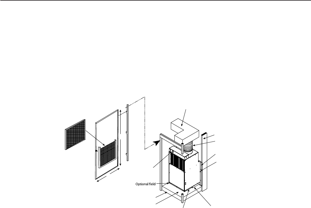
Exterior Wall
Flexible Ductwork
Rigid Ductwork
VPAWP1-8/1-14 Wall Plenum
Plenum Divider
VPDP1 drain pan beneath
unit is required on all
VEA/VHA24 units. Drain pan
must be installed prior to
chassis installation
Chassis is
shipped with
vibration
isolators
installed
3" Clearance on all three
sides minimum for
service and installation
Optional Platform
58"
29"
installed drain pan
(refer to local codes)
VPRG4 Access Panel &
Return Air Filter Grille
Power
Disconnect
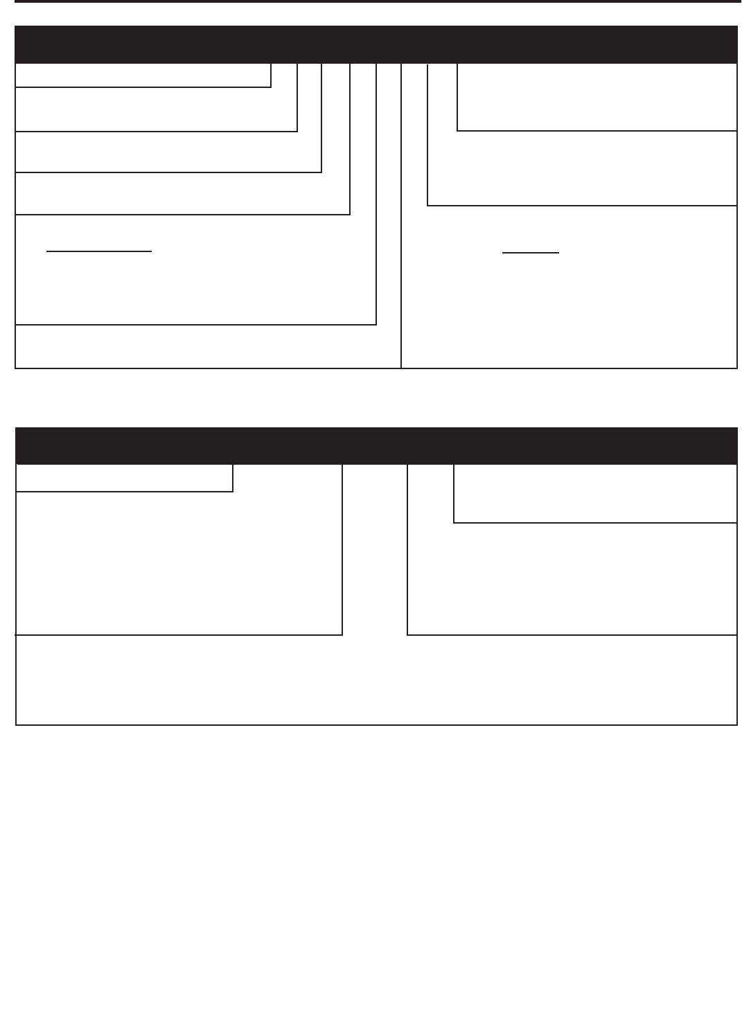
PRODUCT LINE
N = VPAK
V = VPAK
SERIAL NUMBER
MONTH MANUFACTURED
A = Jan D = Apr G = Jul K = Oct
B = Feb E = May H = Aug L = Nov
C = Mar F = Jun J = Sep M = Dec
YEAR MANUFACTURED
LK = 2000
LA = 2001
LB = 2002
LC = 2003
LD = 2004
LE = 2005
LF = 2006
LG = 2007
LH = 2008
LJ = 2009
ELECTRIC HEATER SIZE
A-Series
00 = No electric heat
25 = 2.5 KW
34 = 3.4 KW
50 = 5.0 KW
75 = 7.5 KW
10 = 10 KW
NOMINAL CAPACITY
A-Series (Btu/h)
09 = 9,000
12 = 12,000
18 = 18,000
24 = 24,000
EN GI NEER ING CODE
OPTIONS
RT = Stan dard Re mote Op er a tion
SP = Sea coast Pro tect ed
VOLTAGE
K = 208/230V-1Ph-60Hz
DESIGN SERIES
A = 32" and 47" Cabinet
E=Cooling with or without electric heat
H=Heat Pump
SERIES
V=Vertical Series
MODEL NUMBER V E A 24 K 50 RT A
Model Identifi cation Guide
PRODUCTION RUN NUMBER
Serial Number Identifi cation Guide
10000 V A J L
5
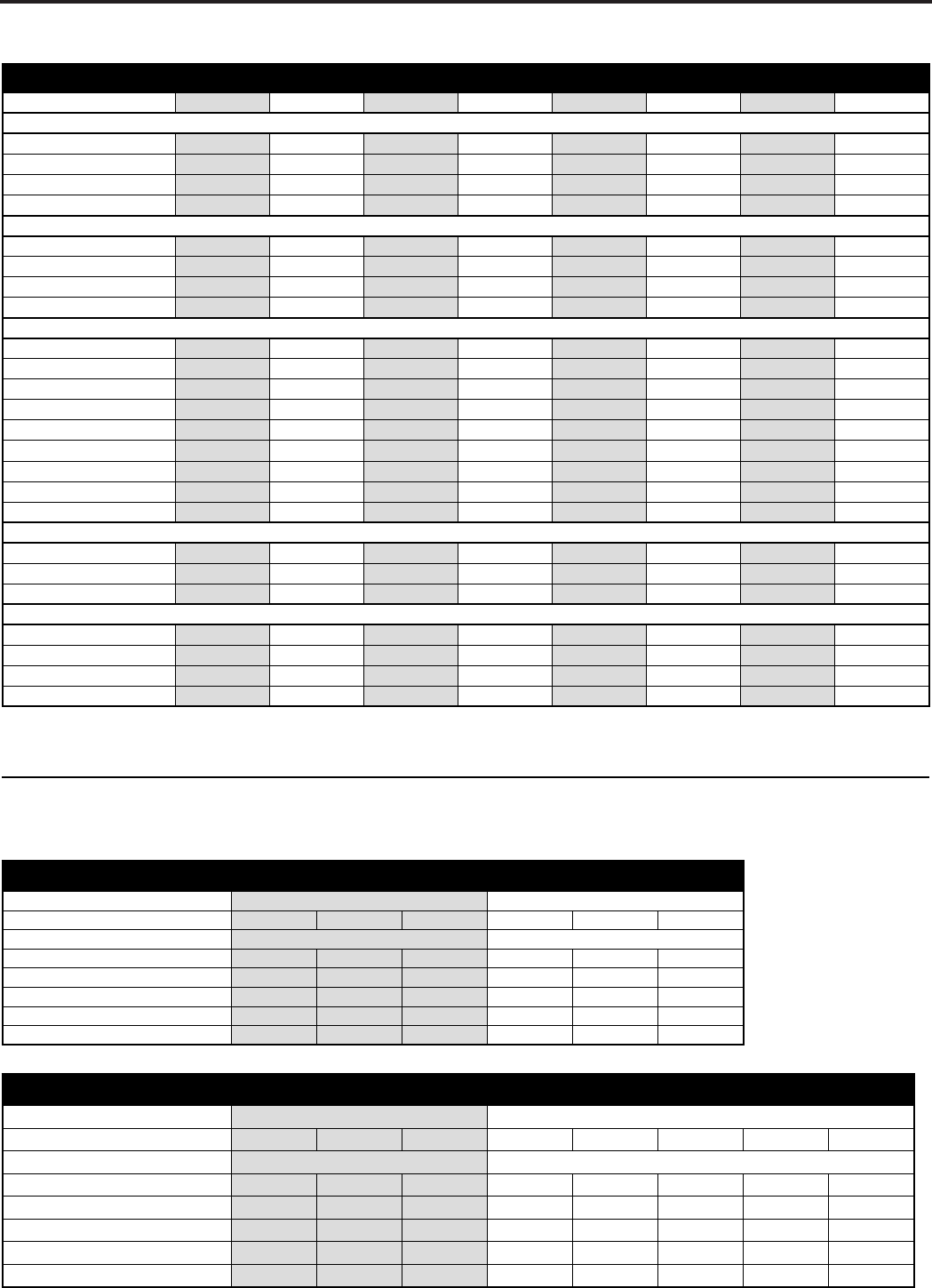
VEA/VHA09-24
VEA09K VEA12K VEA18K VEA24K VHA09K VHA12K VHA18K VHA24K
COOLING DATA
Cooling Btu/h 9500/9300 11800/11500 17500/17300 24000 9500/9300 11800/11500 17500/17300 23500
Cooling Power (W) 880 1093 1882 2526 905 1124 1882 2474
EER 10.8 10.8 9.3 9.5 10.5 10.5 9.3 9.5
Sensible Heat Ratio 0.74 0.72 0.70 0.70 0.74 0.72 0.70 0.70
HEAT PUMP DATA
Heating Btu/h N/A N/A N/A N/A 8500/8300 10600/10400 17000/16800 22500
COP @ 47°F N/A N/A N/A N/A 3.0 3.2 3.0 3.0
Heating Power (W) N/A N/A N/A N/A 830 971 1560 2200
Heating Current (A) N/A N/A N/A N/A 4.4/4.9 5.5/6.1 7.5/8.2 11.4
ELECTRICAL DATA
Voltage (1 Phase, 60 Hz) 230/208 230/208 230/208 230/208 230/208 230/208 230/208 230/208
Volt Range 253-198 253-198 253-198 253-198 253-198 253-198 253-198 253-198
Cooling Current (A) 4.1/4.3 4.9/5.3 8.4/9.0 11.2/12.4 4.2/4.4 5.0/5.5 8.4/9.2 11.2/12.4
Amps L.R. 21 21 42 68 21 21 42 68
Amps F.L. 3.7 4.5 7.5 10.2 3.7 4.5 7.5 10.2
Indoor Motor (HP) 1/4 1/4 1/4 1/4 1/4 1/4 1/4 1/4
Indoor Motor (A) 1.2 1.2 1.2 2 1.2 1.2 1.2 2
Outdoor Motor (HP) N/A N/A N/A 1/4 N/A N/A N/A 1/4
Outdoor Motor (A) N/A N/A N/A 2 N/A N/A N/A 2
AIRF L OW DATA
Indoor CFM* 300 350 450 610 300 420 450 610
Vent CFM 60 60 60 80 60 60 60 80
Max. ESP .3" .3" .3" .4" .3" .3" .3" .4"
P H YSICAL DATA
Dimensions (W x D x H)
Net Weight (Lbs) 114 124 144 167 114 125 144 167
Shipping Weight (Lbs) 125 135 155 180 125 135 155 180
R-22 Charge 25 29 42 68.5 23.5 27 42 63.5
* Normal Value Wet Coil @ .1" ESP.
VEA/VHA09,12
VE/VHA09 VE/VHA12
HEATER WATTS 2500/2050 3400/2780 5000/4090 2500/2050 3400/2780 5000/4090
VOLTAGE 230/208 230/208
HEATING BTUh 8500/7000 11600/9500 17000/13900 8500/7000 11600/9500 17000/13900
HEATING CURRENT (AMPS) 10.6/9.3 14.5/12.5 20.9/18.2 10.6/9.3 14.5/12.5 20.9/18.2
MINIMUM CIRCUIT AMPACITY 15 19.9 27.9 15 19.9 27.9
BRANCH CIRCUIT FUSE (AMPS) 15 20 30 15 20 30
BASIC HEATER SIZE 2.5 Kw 3.4 Kw 5.0 Kw 2.5 Kw 3.4 Kw 5.0 Kw
VEA/VHA18,24
VE/VHA18 VE/VHA24
HEATER WATTS 2500/2050 3400/2780 5000/4090 2500/2050 3400/2780 5000/4090 7500/6135 10000/8180
VOLTAGE 230/208 230/208
HEATING BTUh 8500/7000 11600/9500 17000/13900 8500/7000 11600/9500 17000/13900 25598/20939 34130/27918
HEATING CURRENT (AMPS) 10.6/9.3 14.5/12.5 20.9/18.2 10.9/9.9 14.8/13.4 21.7/19.7 32.6/29.5 43.5/39.3
MINIMUM CIRCUIT AMPACITY 15 19.9 27.9 17.2/15.9 22.1/20.3 30.7/28.1 44.3/40.4 57.9/52.7
BRANCH CIRCUIT FUSE (AMPS) 15 20 30 25/25 25/25 35/30 45/45 60/60
BASIC HEATER SIZE 2.5 Kw 3.4 Kw 5.0 Kw 2.5 Kw 3.4 Kw 5.0 Kw 7.5 Kw 10.0 Kw
23⅛ x 23⅛ x 32¾23⅛ x 23⅛ x 32¾23⅛ x 23⅛ x 32¾23⅛ x 23⅛ x 47¼23⅛ x 23⅛ x 47¼23⅛ x 23⅛ x 32¾23⅛ x 23⅛ x 32¾23⅛ x 23⅛ x 32¾
6
* Operation above these listed temperatures may result in lowered
performance or unit fatigue.
* Operation above these listed temperatures may result in lowered
performance or unit fatigue.
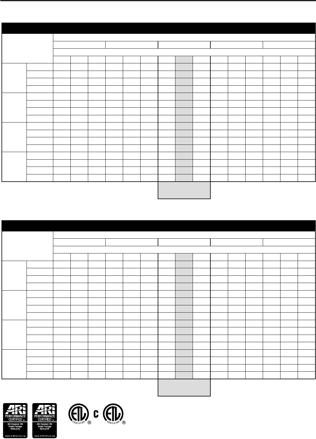
VEA - Extended Cooling Performance
OUTDOOR DRY BULB TEMP. (DEGREES F AT 40% R.H.)
75 85 95 105 110
INDOOR WET BULB TEMP. (DEGREES F AT 80 F D.B.)
72 67 62 72 67 62 72 67 62 72 67 62 72 67 62
VEA09
BTUh 11172 10745 9947 10640 10032 9253 10222 9500 8408 9576 8503 7496 9049 7918 6987
WATTS 718 730 737 782 790 800 880 880 880 951 950 953 994 994 997
AMPS 3.4 3.4 3.5 3.7 3.7 3.7 4.1 4.10 4.1 4.4 4.4 4.4 4.6 4.6 4.6
SHR 0.51 0.69 0.93 0.52 0.71 0.95 0.52 0.74 0.95 0.53 0.78 0.96 0.55 0.81 0.95
VEA12
BTUh 13877 13346 12355 13216 12461 11493 12697 11800 10443 11894 10561 9310 11240 9835 8679
WATTS 892 906 916 972 982 994 1093 1093 1093 1182 1180 1184 1235 1235 1239
AMPS 4.1 4.1 4.1 4.4 4.4 4.4 4.9 4.90 4.9 5.3 5.3 5.3 5.5 5.5 5.5
SHR 0.49 0.67 0.9 0.5 0.7 0.92 0.51 0.72 0.92 0.52 0.76 0.93 0.53 0.79 0.93
VEA18
BTUh 20580 19793 18323 19600 18480 17045 18830 17500 15488 17640 15663 13808 16669 14586 12871
WATTS 1536 1560 1577 1673 1690 1711 1882 1882 1882 2034 2033 2038 2127 2126 2133
AMPS 7 7 7.1 7.5 7.5 7.6 8.4 8.40 8.4 9 9 9.1 9.5 9.5 9.5
SHR 0.48 0.65 0.88 0.49 0.68 0.89 0.49 0.70 0.9 0.5 0.74 0.9 0.52 0.76 0.9
VEA24
BTUh 28224 27144 25128 26880 25344 23376 25824 24000 21240 24192 21480 18936 22860 20004 17652
WATTS 2061 2094 2117 2246 2268 2296 2526 2526 2526 2731 2728 2736 2854 2853 2863
AMPS 9.3 9.3 9.4 10 10 10.1 11.1 11.20 11.3 12.1 12.1 12.1 12.6 12.6 12.6
SHR 0.48 0.65 0.88 0.49 0.68 0.89 0.49 0.70 0.9 0.5 0.74 0.9 0.52 0.76 0.9
RATING POINT
ARI 310/380
VHA - Extended Cooling Performance
OUTDOOR DRY BULB TEMP. (DEGREES F AT 40% R.H.)
75 85 95 105 110
INDOOR WET BULB TEMP. (DEGREES F AT 80 F D.B.)
72 67 62 72 67 62 72 67 62 72 67 62 72 67 62
VHA09
BTUh 11172 10745 9947 10640 10032 9253 10222 9500 8408 9576 8503 7496 9049 7918 6987
WATTS 738 750 758 805 813 823 905 905 905 978 977 980 1023 1022 1026
AMPS 3.5 3.5 3.5 3.7 3.8 3.8 4.2 4.20 4.2 4.5 4.5 4.5 4.7 4.7 4.7
SHR 0.51 0.69 0.93 0.52 0.71 0.95 0.52 0.74 0.95 0.53 0.78 0.96 0.55 0.81 0.95
VHA12
BTUh 13877 13346 12355 13216 12461 11493 12697 11800 10443 11894 10561 9310 11240 9835 8679
WATTS 917 932 942 999 1009 1022 1124 1124 1124 1215 1214 1217 1270 1270 1274
AMPS 4.1 4.2 4.2 4.5 4.5 4.5 5 5.00 5 5.4 5.4 5.4 5.6 5.6 5.6
SHR 0.49 0.67 0.9 0.5 0.7 0.92 0.51 0.72 0.92 0.52 0.76 0.93 0.53 0.79 0.93
VHA18
BTUh 20580 19793 18323 19600 18480 17045 18830 17500 15488 17640 15663 13808 16669 14586 12871
WATTS 1536 1560 1577 1673 1690 1711 1882 1882 1882 2034 2033 2038 2127 2126 2133
AMPS 7 7 7.1 7.5 7.5 7.6 8.4 8.40 8.4 9 9 9.1 9.5 9.5 9.5
SHR 0.48 0.65 0.88 0.49 0.68 0.89 0.49 0.70 0.9 0.5 0.74 0.9 0.52 0.76 0.9
VHA24
BTUh 27636 26579 24605 26320 24816 22889 25286 23500 20798 23688 21033 18542 22384 19587 17284
WATTS 2019 2051 2073 2199 2222 2249 2474 2474 2474 2674 2672 2679 2796 2794 2804
AMPS 9.3 9.3 9.4 10 10 10.1 11.1 11.20 11.3 12.1 12.1 12.1 12.6 12.6 12.6
SHR 0.48 0.65 0.88 0.49 0.68 0.89 0.49 0.70 0.9 0.5 0.74 0.9 0.52 0.76 0.9
RATING POINT
ARI 310/380
7
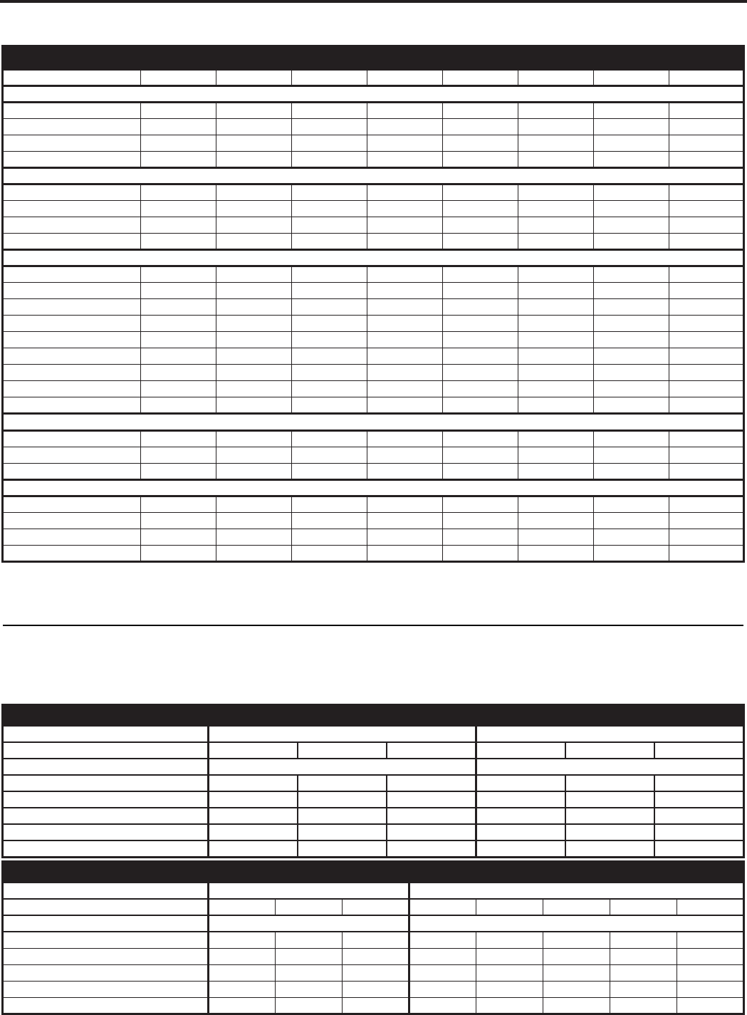
VEA/VHA09-24
VEA09K VEA12K VEA18K VEA24K VHA09K VHA12K VHA18K VHA24K
COOLING D A T A
Cooling Btu/h 9500/9300 11800/11500 18000/17800 24000 9500/9300 11800/11500 18000/17800 23500
Cooling Power (W) 880 1093 2070 2526 905 1124 2070 2474
EER 10.8 10.8 8.7 9.5 10.5 10.5 8.7 9.5
Sensible Heat Ratio 0.74 0.72 0.70 0.70 0.74 0.72 0.70 0.70
HEA T PUMP D A T A
Heating Btu/h N/A N/A N/A N/A 8500/8300 10600/10400 15700/15500 22500
COP @ 47°F N/A N/A N/A N/A 3.0 3.2 3.0 3
Heating Power (W) N/A N/A N/A N/A 830 971 1705 2200
Heating Current (A) N/A N/A N/A N/A 4.4/4.9 5.5/6.1 9.2/10.2 11.4
ELECTRICAL D A T A
Voltage (1 Phase, 60 Hz) 230/208 230/208 230/208 230/208 230/208 230/208 230/208 230/208
Volt Range 253-198 253-198 253-198 253-198 253-198 253-198 253-198 253-198
Cooling Current (A) 4.1/4.3 4.9/5.3 9.2/10.2 11.2/12.4 4.2/4.4 5.0/5.5 9.2/10.2 11.2/12.4
Amps L.R. 21 21 47 68 21 21 47 68
Amps F.L. 3.7 4.5 7.9 10.2 3.7 4.5 7.9 10.2
Indoor Motor (HP) 1/4 1/4 1/4 1/4 1/4 1/4 1/4 1/4
Indoor Motor (A) 1.2 1.2 1.421.2 1.2 1.4 2
Outdoor Motor (HP) N/A N/A N/A 1/4 N/A N/A N/A 1/4
Outdoor Motor (A) N/A N/A N/A 2 N/A N/A N/A 2
AIRFLOW D A T A
Indoor CFM* 300 350 550 750 300 375 550 750
Vent CFM 60 60 60 80 60 60 60 80
Max. ESP .3" .3" .3" .3" .3" .3" .3" .3"
PHYSICAL D A T A
Dimensions (W x D x H) 23⅛ x 23⅛ x 32¾23⅛ x 23⅛ x 32¾23⅛ x 23⅛ x 32¾23⅛ x 23⅛ x 47¼23⅛ x 23⅛ x 47¼23⅛ x 23⅛ x 32¾23⅛ x 23⅛ x 32¾23⅛ x 23⅛ x 32¾
Net Weight (Lbs) 114 124 144 167 114 125 144 167
Shipping Weight (Lbs) 125 135 155 180 125 135 155 180
R-22 Charge 25 29 42 68.5 23.5 27 42 63.5
VE A / V HA09,12
21AHV/EV90AHV/EV
Heater Watts 2500/2050 3400/2780 5000/4090 2500/2050 3400/2780 5000/4090
802/032802/032egatloV
Heating Btu/h 8500/7000 11600/9500 17000/13900 8500/7000 11600/9500 17000/13900
Heating Current (Amps) 10.6/9.3 14.5/12.5 20.9/18.2 10.6/9.3 14.5/12.5 20.9/18.2
Minimum Circuit Ampacity 15 19.9 27.9 15 19.9 27.9
Branch Circuit Fuse (Amps) 15 20 30 15 20 30
Basic Heater Size 2.5 Kw 3.4 Kw 5.0 Kw 2.5 Kw 3.4 Kw 5.0 Kw
VEA/VHA18,24
42AHV/EV81AHV/EV
Heater Watts 2500/2050 3400/2780 5000/4090 2500/2050 3400/2780 5000/4090 7500/6135 10000/8180
802/032802/032egatloV
Heating Btu/h 8500/7000 11600/9500 17000/13900 8500/7000 11600/9500 17000/13900 25598/20939 34130/27918
Heating Current (Amps) 10.6/9.3 14.5/12.5 20.9/18.2 10.9/9.9 14.8/13.4 21.7/19.7 32.6/29.5 43.5/39.3
Minimum Circuit Ampacity 15 19.9 27.9 17.2/15.9 22.1/20.3 30.7/28.1 44.3/40.4 57.9/52.7
Branch Circuit Fuse (Amps) 15 20 30 25/25 25/25 35/30 45/45 60/60
Basic Heater Size 2.5 Kw 3.4 Kw 5.0 Kw 2.5 Kw 3.4 Kw 5.0 Kw 7.5 Kw 10.0 Kw
* Normal Value Wet Coil @ .1" ESP.
8
9
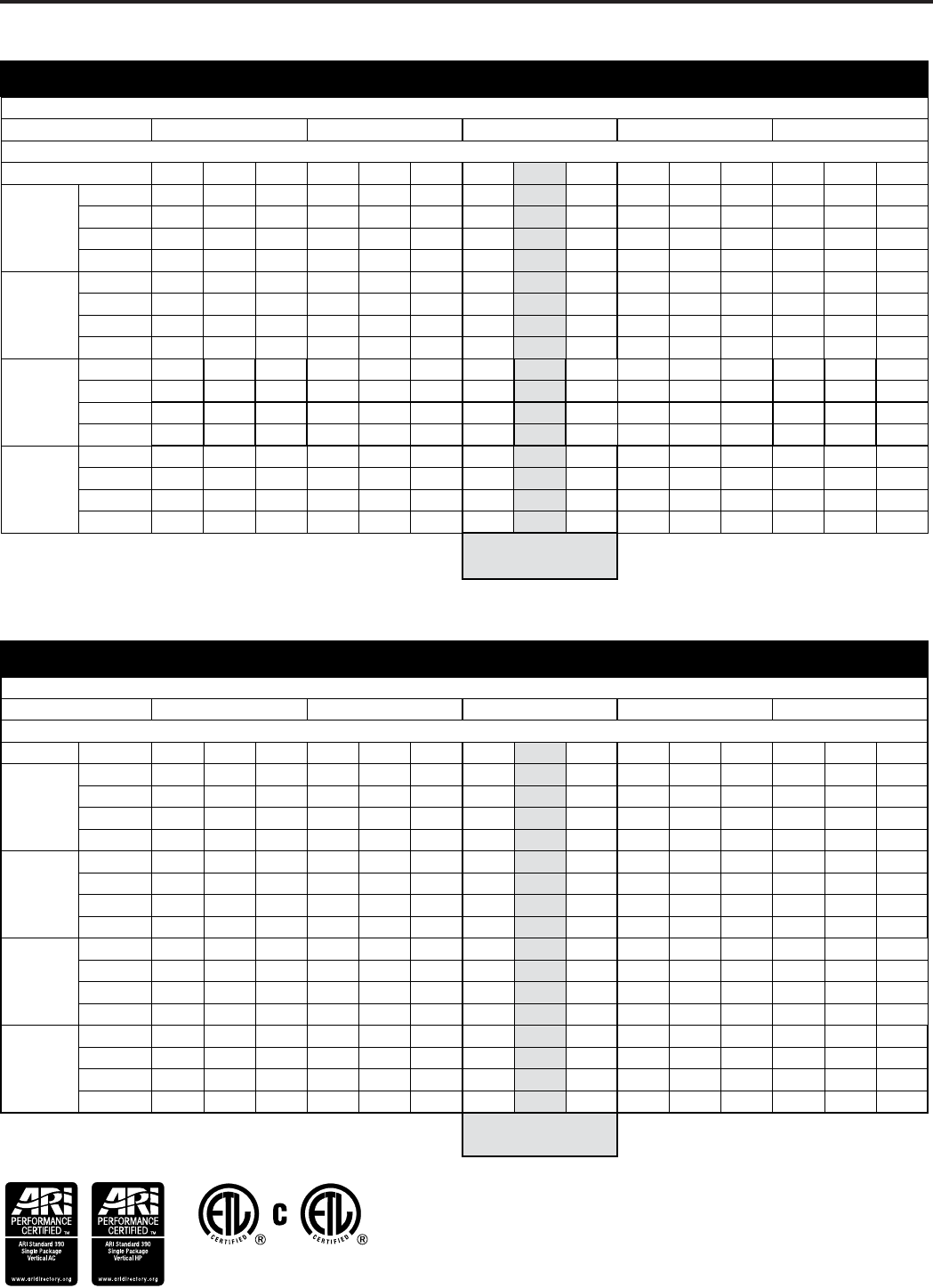
VEA - Extended Cooling Performance
OUTDOOR DRY BULB TEMP. (DEGREES F AT 40% R.H.)
75 85 95 105 110
INDOOR WET BULB TEMP. (DEGREES F AT 80 F D.B.)
72 67 62 72 67 62 72 67 62 72 67 62 72 67 62
VEA09
BTUh 11172 10745 9947 10640 10032 9253 10222 9500 8408 9576 8503 7496 8522 7334 6479
WATTS 718 730 737 782 790 800 880 880880 951 950 953 1038 1038 1042
AMPS 3.4 3.4 3.5 3.7 3.7 3.7 4.1 4.10 4.1 4.4 4.4 4.4 4.8 4.8 4.8
SHR 0.51 0.69 0.93 0.52 0.71 0.95 0.52 0.74 0.95 0.53 0.78 0.96 0.56 0.83 0.95
VEA12
BTUh 13877 13346 12355 13216 12461 11493 12697 11800 10443 11894 10561 9310 10585 9110 8048
WATTS 892 906 916 972 982 994 1093 1093 1093 1182 1180 1184 1289 1289 1294
AMPS 4.1 4.1 4.1 4.4 4.4 4.4 4.9 4.90 4.9 5.3 5.3 5.3 5.8 5.8 5.8
SHR 0.49 0.67 0.9 0.5 0.7 0.92 0.51 0.72 0.92 0.52 0.76 0.93 0.54 0.81 0.92
VEA18
BTUh 21168 20358 18846 20160 19008 17532 19368 18000 15930 18144 16110 14202 16146 13896 12276
WATTS 1536 1560 1577 1673 1690 1711 1882 1882 1882 2034 2033 2038 2219 2219 2228
AMPS 7.7 7.7 7.8 8.3 8.3 8.4 9.3 9.30 9.3 10 10 10 10.9 10.9 11
SHR 0.48 0.65 0.88 0.49 0.68 0.89 0.49 0.70 0.9 0.5 0.74 0.9 0.53 0.79 0.9
VEA24
BTUh 28224 27144 25128 26880 25344 23376 25824 24000 21240 24192 21480 18936 21528 18528 16368
WATTS 2061 2094 2117 2246 2268 2296 2526 2526 2526 2731 2728 2736 2978 2978 2991
AMPS 9.3 9.3 9.4 10 10 10.1 11.1 11.20 11.3 12.1 12.1 12.1 13.1 13.1 13.2
SHR 0.48 0.65 0.88 0.49 0.68 0.89 0.49 0.70 0.9 0.5 0.74 0.9 0.53 0.79 0.9
RATING POINT
ARI 310/380
VHA - Extended Cooling Performance
OUTDOOR DRY BULB TEMP. (DEGREES F AT 40% R.H.)
75 85 95 105 110
INDOOR WET BULB TEMP. (DEGREES F AT 80 F D.B.)
72 67 62 72 67 62 72 67 62 72 67 62 72 67 62
VHA09
BTUh 11172 10745 9947 10640 10032 9253 10222 9500 8408 9576 8503 7496 8522 7334 6479
WATTS 738 750 758 805 813 823 905 905 905 978 977 980 1067 1067 1072
AMPS 3.5 3.5 3.5 3.7 3.8 3.8 4.2 4.20 4.2 4.5 4.5 4.5 4.9 4.9 4.9
SHR 0.51 0.69 0.93 0.52 0.71 0.95 0.52 0.74 0.95 0.53 0.78 0.96 0.56 0.83 0.95
VHA12
BTUh 13877 13346 12355 13216 12461 11493 12697 11800 10443 11894 10561 9310 10585 9110 8048
WATTS 917 932 942 999 1009 1022 1124 1124 1124 1215 1214 1217 1325 1325 1331
AMPS 4.1 4.2 4.2 4.5 4.5 4.5 5 5.00 5 5.4 5.4 5.4 5.9 5.9 5.9
SHR 0.49 0.67 0.9 0.5 0.7 0.92 0.51 0.72 0.92 0.52 0.76 0.93 0.54 0.81 0.92
VHA18
BTUh 21168 20358 18846 20160 19008 17532 19368 18000 15930 18144 16110 14202 16146 13896 12276
WATTS 1536 1560 1577 1673 1690 1711 1882 1882 1882 2034 2033 2038 2219 2219 2228
AMPS 7.6 7.7 7.7 8.2 8.2 8.3 9.2 9.20 9.2 9.9 9.9 9.9 10.8 10.8 10.8
SHR 0.48 0.65 0.88 0.49 0.68 0.89 0.49 0.70 0.9 0.5 0.74 0.9 0.53 0.79 0.9
VHA24
BTUh 27636 26579 24605 26320 24816 22889 25286 2350020798 23688 21033 18542 21080 18142 16027
WATTS 2019 2051 2073 2199 2222 2249 2474 2474 2474 2674 2672 2679 2917 2917 2929
AMPS 9.3 9.3 9.4 10 10 10.1 11.1 11.2 11.3 12.1 12.1 12.1 13.1 13.1 13.2
SHR 0.48 0.65 0.88 0.49 0.68 0.89 0.49 0.7 0.9 0.5 0.74 0.9 0.53 0.79 0.9
RATING POINT
ARI 310/380
* Operation above these listed temperatures may result in lowered
performance or unit fatigue.
* Operation above these listed temperatures may result in lowered
performance or unit fatigue.
10
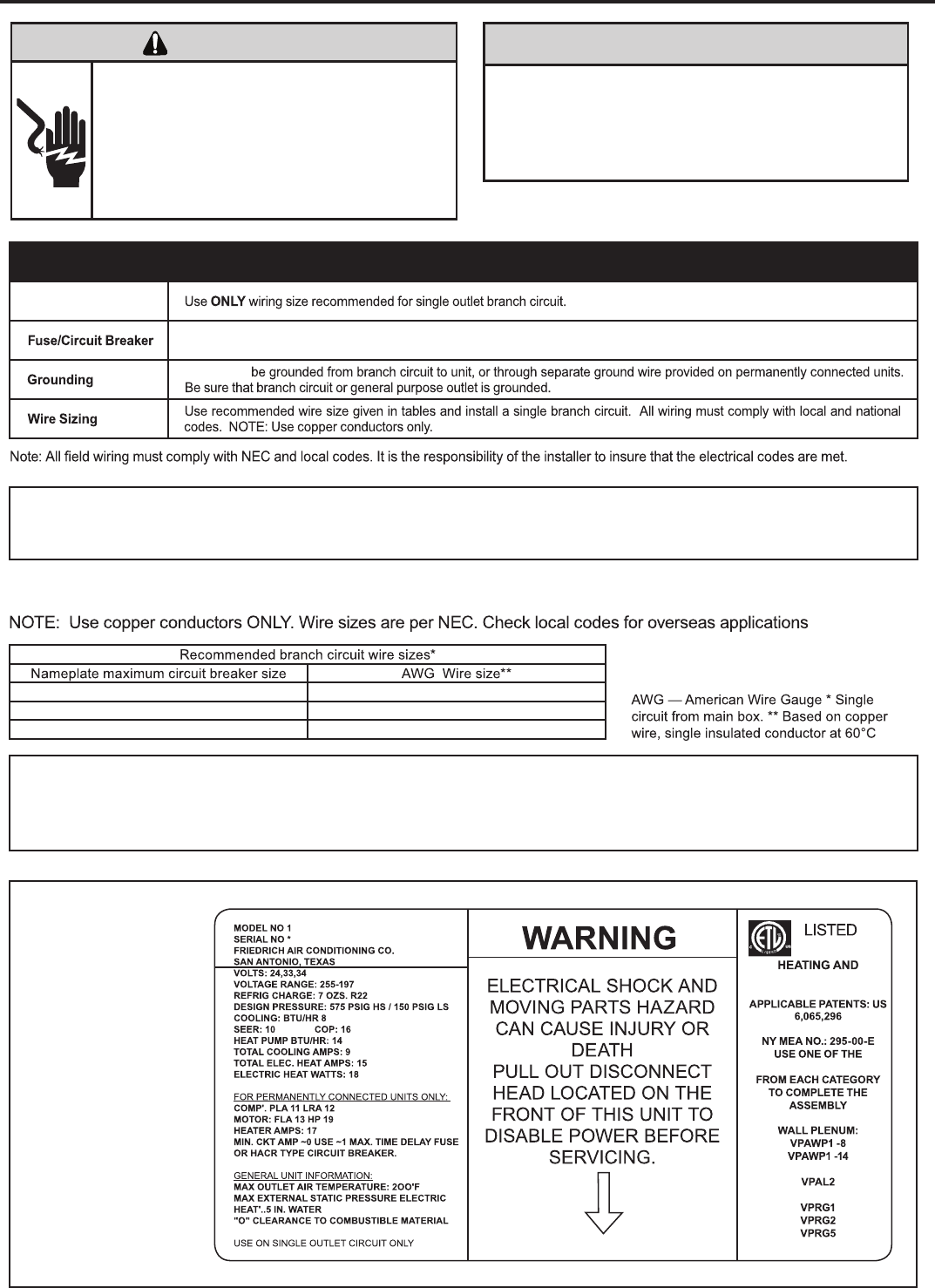
ELECTRICAL REQUIREMENTS
WireSize
UnitMUST
Sample Nameplate120524
COOLING EQUIPMENT
FOLLOWING ITEMS
OUTDOOR GRILLE
INDOORGRILLE
SAMPLE
Electrical Rating Tables
41A51
21A02
01A03
All 208/230v chassis must be hard wired with properly sized breaker. See nameplate for specic chassis electrical
Supply voltage
requirements. See gure 9 (Page 12) for unit wiring and wall thermostat wiring. See Electrical Rating Table below for wire siz
Use HACR type breakers to avoid nuisance trips. All eld wiring must be done in accordance with NEC and local codes.
NOTICE
ELECTRIC SHOCK HAZARD
WARNING
Turn off electric power before service or instal-
lation. All electrical connnections and wiring
MUST be installed by a qualified electrician and
conform to the National Electrical Code and all
local codes which have jurisdiction. Failure to
do so can result in personal injury and/or death.
ELECTRIC SHOCK HAZARD
Not following the previous WARNING could result in fire or
electrically unsafe conditions which could cause moderate
or serious property damage. Read, understand and follow
the previous warning.
Supply voltage to the unit should be a nominal 208/230 volts. It must be between 197 volts and 253 volts. Supply voltage to
the unit should be checked WITH THE UNIT IN OPERATION. Voltage readings outside the specified range can be expected
to cause operating problems. Their cause MUST be investigated and corrected.
“Use ONLY time delayed fused disconnect or HACR type circuit breaker as indicated on the unit’s rating plate (see
sample on this page). Proper current protection to the unit is the responsibility of the owner”.
11
CONNECTIONS
Remote Thermostat
To control the unit with a wall-mounted thermostat:
1) Pull the disconnect switch.
2) Unscrew and remove the control box panel.
3) After selecting which side you want to run your thermostat
wire through, run the wires through the side hole in the box
to reach the connection terminal for the wiring.
4) Make the wire connections, appropriately matching the
wires as shown in the wiring diagram.
5) Once each wire is matched and connected, the unit is now
controlled by the thermostat.
6) Reattach the control box cover.
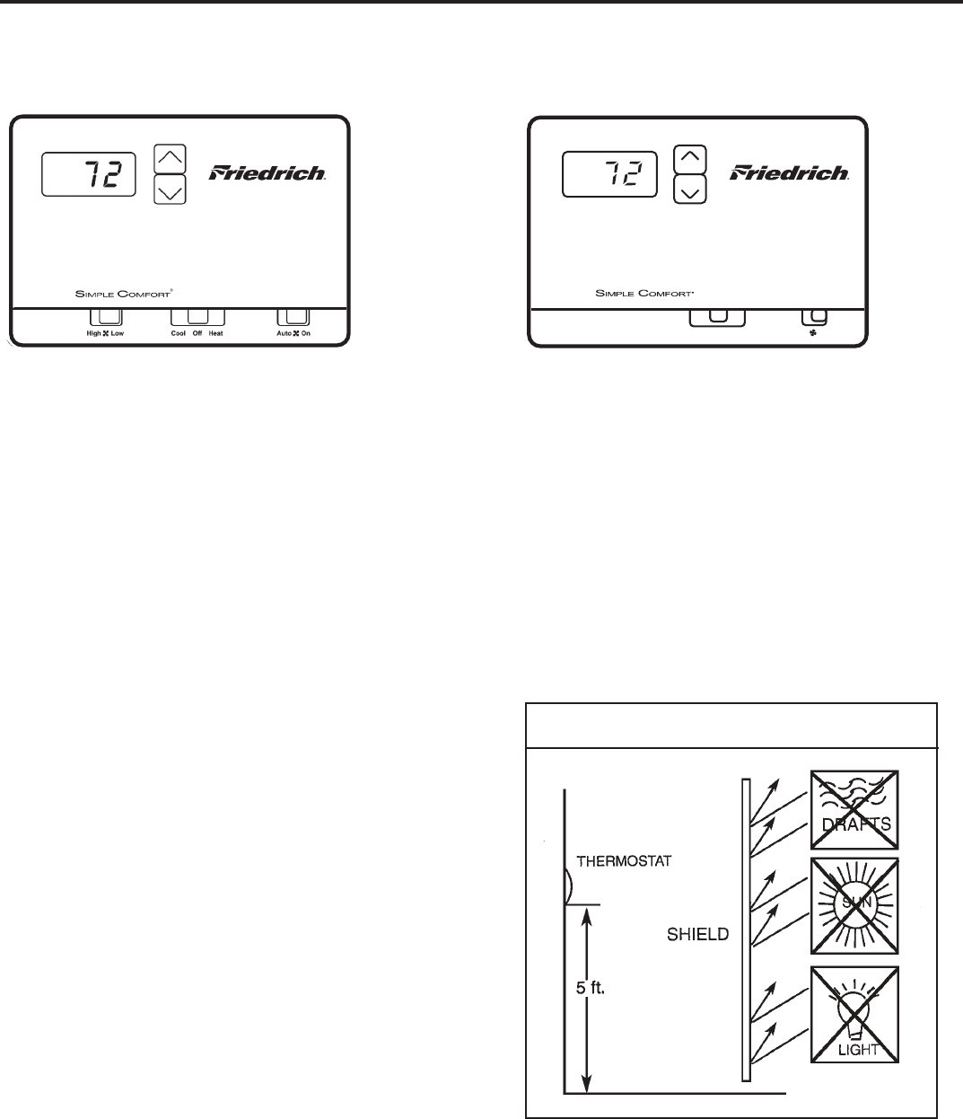
RT5 (Two speed fan) RT4 (One speed fan)
Cool Off HeatAuto On
All Friedrich Vert-I-Pak units are factory configured to be
controlled by using a 24V single stage remote wall mounted
thermostat. The thermostat may be auto or manual changeover
as long as the control configuration matches that of the
Vert-I-Pak unit.
NOTE: An improperly operating, or poorly located room
thermostat can be the source of perceived equipment
problems. A careful check of the thermostat and wiring
must be made then to insure that it is not the source of
problems.
Manual Changeover Thermostat
For Heat Pump equipped units: a single stage, heat/cool
thermostat with a terminal for a reversing valve operation is
required. Terminal “B” should be continuously energized in the
heat mode and terminal “G” should be energized whenever
there is a call for heating or cooling. (Typically, a single stage,
heat/cool thermostat designed for use with electric heat
systems will meet the above requirements).
Location
The thermostat should not be mounted where it may be
affected by drafts, discharge air from registers (hot or cold),
or heat radiated from the sun or appliances.
The thermostat should be located about 5 Ft. above the
fl oor in an area of average temperature, with good air
circulation. Close proximity to the return air grille is the
best choice.
Mercury bulb type thermostats MUST be level to control
temperature accurately to the desired set-point. Electronic
digital type thermostats SHOULD be level for aesthetics.
Thermostat Location
12
CONNECTIONS
Desk Control Terminals
The Friedrich VERT-I-PAK has built-in provisions for
connection to an external switch to control power to the unit.
The switch can be a central desk control system or even a
normally open door switch.
For desk control operation, connect one side of the switch to
the D1 terminal and the other to the D2 terminal (See figure 9).
Whenever the switch closes, the unit operation will stop.
Maximum Wire Length for Desk Control Switch
Wire Size Maximum Length
#24 400 ft.
#22 600 ft.
#20 900 ft.
#18 1500 ft.
#16 2000 ft.
Auxiliary Fan Control
The Smart Center also has the ability to control a 24VAC
relay to activate an auxiliary, or transfer, fan. The outputs
are listed as F1 and F2 on the control board.
To connect the relay, simply wire one side of the relay to
F1 and the other side to F2. Anytime that the fan runs, the
terminals will send a 24VAC signal to the relay. The relay
must be 24 VAC, 50mA or less.
Note: The relay and auxiliary fans must be field supplied.
Note: The desk
control system and
switches must be
field supplied.
Thermostat Connections
Thermostat Configuration
C = Common Ground
W = Call for Heating
Y = Call for Cooling
R = 24V Power from Unit
GL = Call for Fan (Low Speed)
GH = Call for Fan (High Speed)
B = Reversing Valve Energized in heating mode
*If only one G terminal is present on thermostat, connect
to GL for low fan or to GH for high fan operation.
NOTE: It is the installer’s responsibility to ensure that all
control wiring connections are made in accordance with
the Freidrich installation instructions. Improper connec-
tion of the thermostat control wiring and/or tampering with
the unit’s internal wiring can void the equipment warranty.
Questions concerning proper connections to the unit
should be directed to the factory: 210-357-4400.
An improperly configured t-stat can be the
cause of improper operation. Ensure to
correctly configure the t-stat (see owner’s
manual).

13
The new Friedrich Vert-I-Pak has state of the art features to improve guest comfort and conserve energy. Through
the use of specically designed control software, Friedrich has accomplished what other Manufacturer’s have only
attempted – a quiet, dependable, affordable and easy to use Vert-I-Pak.
Below is a list of standard features on every Friedrich VPAK and their benet to the owner.
Quiet Start/Stop
Fan Delay
The fan start and stop delays prevent abrupt changes in room acoustics due to the compressor energizing
or stopping immediately. Upon call for cooling or heating the unit fan will run for ve seconds prior to en-
ergizing the compressor. Also, the fan off delay allows for “free cooling” by utilizing the already cool indoor
coil to its maximum capacity by running for 30 seconds after the compressor.
Remote Thermostat
Operation VPAK units are thermostat controlled.
Internal Diagnostic
Program
The new Friedrich digital VPAK features a self diagnostic program that can alert maintenance to compo-
nent failures or operating problems. The internal diagnostic program saves properties valuable time when
diagnosing running problems.
Service Error Code
Storage
The self diagnosis program will also store error codes in memory if certain conditions occur and correct
themselves such as extreme high or low operating conditions or activation of the room freeze protection
feature. Storing error codes can help properties determine if the unit faced obscure conditions or if an error
occurred and corrected itself.
Room Freeze
Protection
When the VPAK senses that the indoor room temperature has fallen to 40°F the unit will cycle on high fan
and the electric strip heat to raise the room temperature to 46°F then cycle off again. This feature works
regardless of the mode selected and can be turned off. The control will also store the Room Freeze cycle
in the service code memory for retrieval at a later date. This feature ensures that unoccupied rooms do not
reach freezing levels where damage can occur to plumbing and xtures.
Random
Compressor Restart
Multiple compressors starting at once can often cause electrical overloads and premature unit failure.
The random restart delay eliminates multiple units from starting at once following a power outage or initial
power up. The compressor delay will range from 180 to 240 seconds.
Digital Defrost
Thermostat
The new Friedrich VPAK uses a digital thermostat to accurately monitor the outdoor coil conditions to allow
the heat pump to run whenever conditions are correct. Running the VPAK in heat pump mode save energy
and reduces operating costs. The digital thermostat allows maximization of heat pump run time.
Instant Heat
Heat Pump Mode
Heat pump models will automatically run the electric heater during compressor lock-out to quickly provide
heat when initially energized, then return to heat pump mode. This ensures that the room is heated quickly
without the usual delay associated with heat pump units.
Emergency Heat
Override
In the event of a compressor failure in heat pump mode the compressor may be locked out to provide heat
through the resistance heater. This feature ensures that even in the unlikely event of a compressor failure
the room temperature can be maintained until the compressor can be serviced.
Desk Control Ready
All electronic VPAK units have low voltage terminals ready to connect a desk control energy management
system. Controlling the unit from a remote location like the front desk can reduce energy usage and
requires no additional accessories at the VPAK.
Indoor Coil Frost
Sensor
The frost sensor protects the compressor from damage in the event that air ow is reduced or low outdoor
temperatures cause the indoor coil to freeze. When the indoor coil reaches 30°F the compressor is
diabled and the fan continues to operate based on demand. Once the coil temperature returns to 45°F the
compressor returns to operation.
Ultra-Quiet Air
System
The VPAK series units feature a indoor fan system design that reduces sound levels without
lowering airow and preventing proper air circulation.
High Efciency The VPAK benets quality components and extensive development to ensure a quiet, efcient and
dependable unit.
Rotary Compressor High efciency rotary compressors are used on all Friedrich VPAKs to maximize durability and efciency.
Auxiliary Fan Ready The VPAK features a 24V AC terminal for connection to an auxiliary fan that may be used to transfer air to
adjoining rooms. Auxiliary fans can provide conditioning to multiple rooms.
14
Low fan
High fan
Fan only
Power
Temp
Temp
Cool
Heat
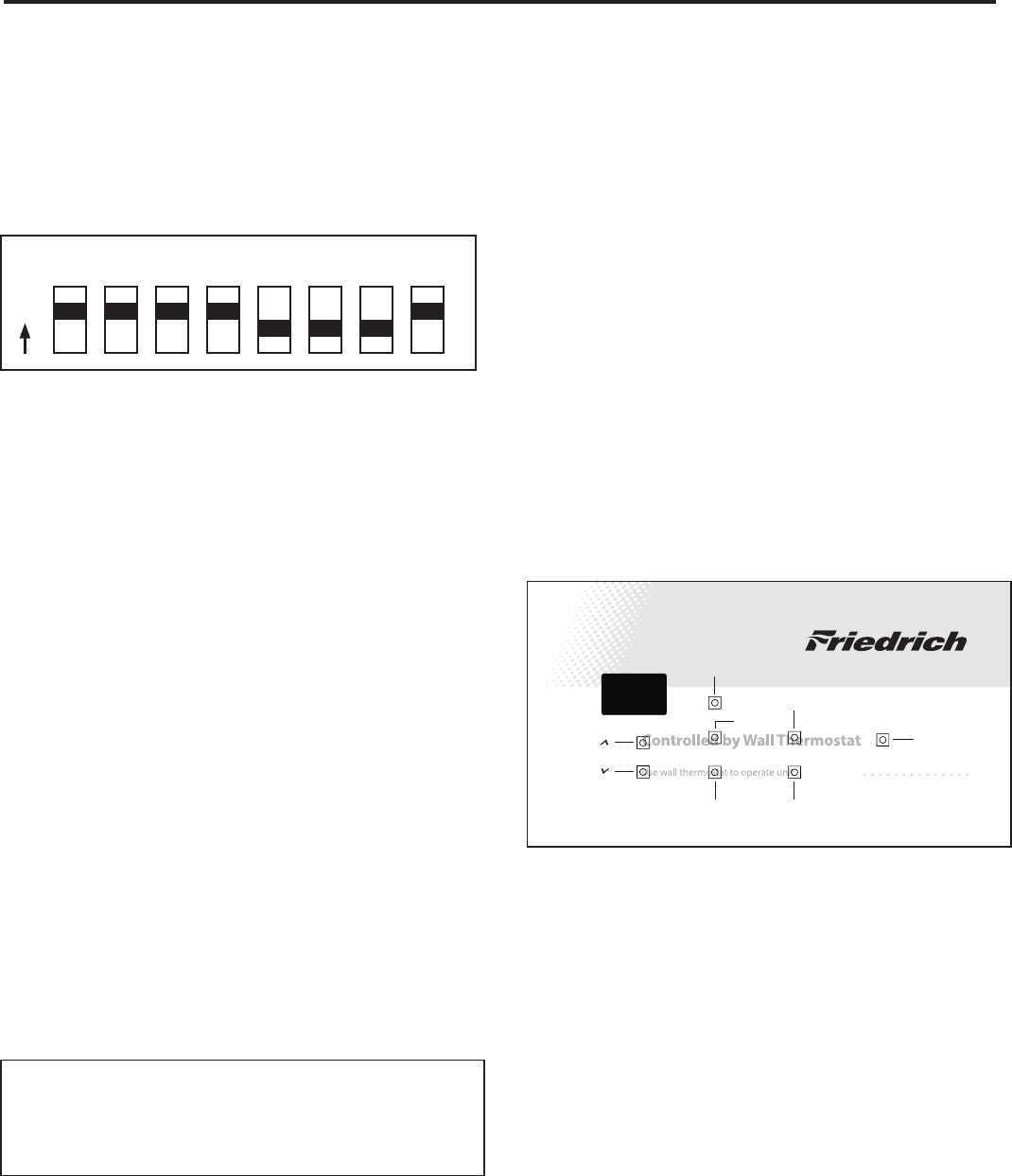
1 2 3 4 5 6 7 8
O
N
Electronic Control Configuration
The adjustable control dip switches are located at the lower
left hand portion of the digital Smart Center. The inputs are
only visible and accessible with the front cover removed from
the Unit.
Factory Dip Switch Configuration
Dip Switch Setting
Switches 1-4 ON
Switch 5-7 OFF
Switch 8 ON
Room Freeze Protection – Switch 6
Units are shipped from the factory with the room freeze protec-
tion disabled. Room Freeze Protection can be switched on at
the owner’s preference by moving Dip Switch 6 to ‘ON’. This
feature will monitor the indoor room conditions and in the event
that the room falls below 40°F the unit will cycle on high fan with
the electric heater. This occurs regardless of mode.
Emergency Heat Override – Switch 7
Units are shipped from the factory with the room emergency
heat override disabled. In the unlikely event of a compressor
failure a heat pump unit may be switched to operate in only the
electric heat mode until repairs can be made, by moving Dip
Switch 7 to ‘ON’.
Discharge Air Sensor Override – Switch 8
This switch MUST remain in the “ON” position for Vert-I-Pak
models, since they do not use a discharge air sensor. If the
switch is positioned in the “OFF” position on these models it
will result in the erroneous display Error Code 14 indicating that
the Discharge air temperature sensor is open or shorted.
Note: In order for the control to recognize “Dip” switch
setting changes, the unit must be disconnected
from power supply when making any configuration
changes.
Error Code Diagnostics
The VPAK electronic control continuously monitors the Vert-I-Pak
unit operation and will store error codes if certain conditions
are witnessed. In some cases the unit may take action and shut
the unit off until conditions are corrected.
To access the error code menu press the ‘HEAT’ and ‘HIGH
FAN’ buttons simultaneously for three seconds. If error codes
are present they will be displayed. If multiple codes exist you
can toggle between error codes using the temp up ▲ button. To
clear all codes press the temp down ▼ button for three seconds
while in the error code mode. To exit without losing codes
press the ‘Low Fan’ button.
Button Location for Vert-I-Pak Models
With the remote thermostat escutcheon installed, the button
locations to access the diagnostics mode can be located as
shown below.
Electronic Control Error Code
Diagnostics and Test Mode
* Heat and high fan - access error codes
* Temp up ▲ and temp down ▼ - toggle between error codes
* Low fan - exit error code mode without losing stored error
codes.
* Temp down ▼ - clears all error codes
NOTE: Hold buttons down for three seconds.
15
TEST MODE (
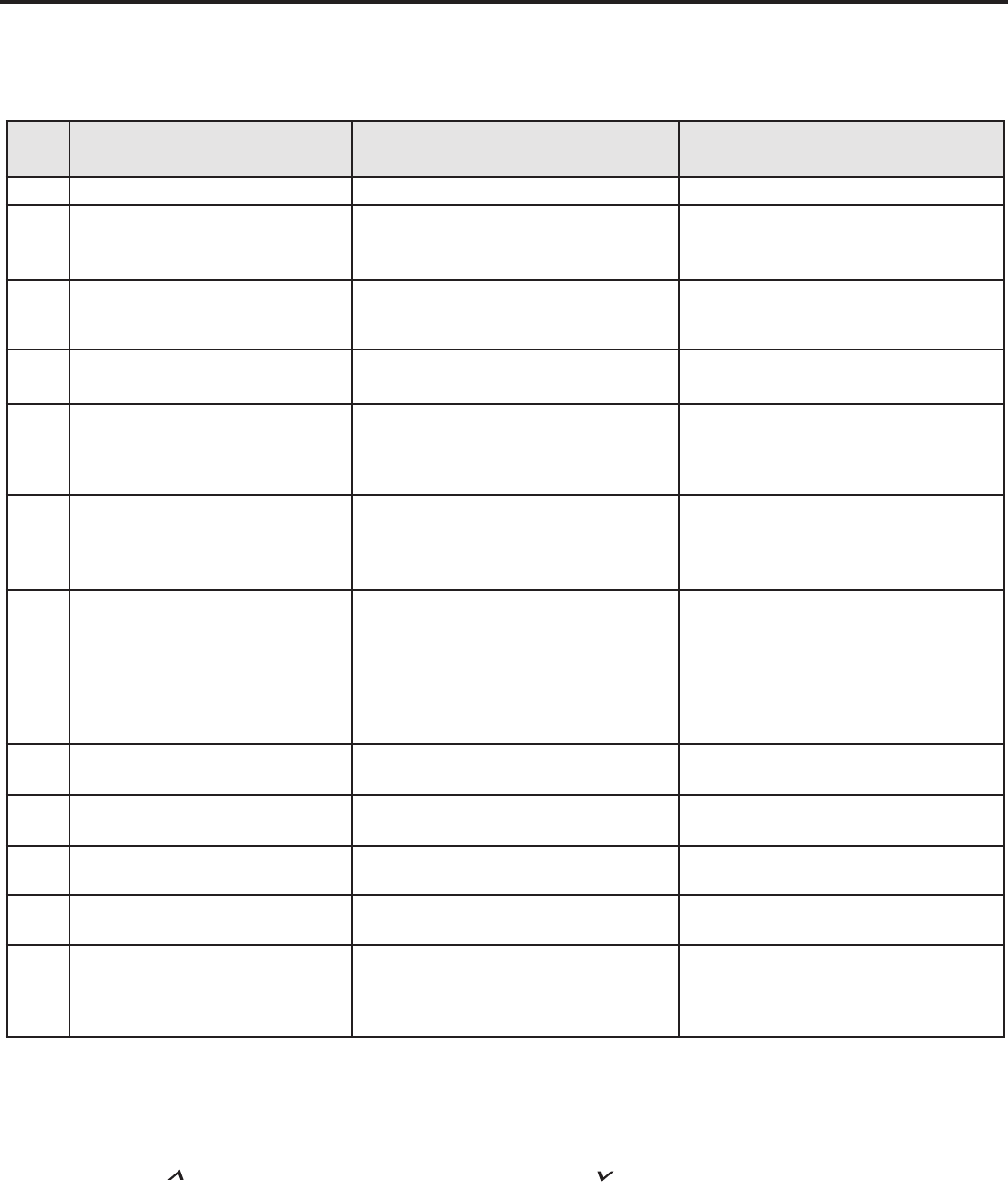
The chart below lists the possible error codes and their description:
Error
Code Code Translation Action Taken by Unit Possible Cause
EF “Error Free” - No Codes Stored None Unit Operating Normally
02 An extreme low voltage condition
exists <198V for 230V units and
<239V for 265V units.
Shut down unit. Display Error code and
ash. Once voltage rises to normal level
system power is restored.
• Inadequate power supply
• Defective breaker
• Blown fuse
03 Return air thermistor sensor open or
short circuit
Set return air sensor = 75°F. Alternately
ash set point and error code. Leave unit
running.
• Defective sensor
04 Indoor coil thermistor sensor open or
short circuit
Set ID coil temp = 40°F. Alternately ash
set point and error code. Leave unit running.
• Defective sensor
05 Outdoor coil thermistor sensor open
or short circuit
Set OD coil temp = 20°F. Alternately ash
set point and error code. Automatically
change over to Electric heat Mode only.
Leave unit running.
• Defective sensor
06 If O.D. coil Temperature > 175° F for
2 consecutive minutes. (Heat Pump
models only)
Alternately ash set point and error code.
Shut unit down for 5 minutes, then try again
2 times, if fails the 3rd time then shut down
unit.
• Dirty coil
• Fan motor failure
• Restricted air ow
• Non-condensables in refrigeration system
07 I.D coil temperature <30° F for 2
consecutive minutes.
Alternately ash set point and error
code. Continue fan operation while the
compressor is locked out until the indoor
coil thermistor reaches 45° F, then energize
the compressor. However, compressor
must still wait a lockout time of 180 to 240
seconds.
• Dirty lters
• Dirty coil
• Fan motor failure
• Restricted airow
• Improper refrigerant charge
• Restriction in refrigerant circuit
08 Unit cycles (Heat or Cool demand) >
9 times per hour
Store error code in memory.
Keep unit running
• Unit oversized
• Low load conditions
09 Unit cycles (Heat or Cool demand) <
3 times per hour
Store Error Code in memory.
Keep unit running
• Unit undersized
• High load conditions
10 Room Freeze Protection triggered Alternately ash set point and error code.
Keep unit running.
• Room temperature fell below 40°F
11 No Signal to “GL or “GH” terminal Shut down unit. Display error code and
ash.
• Defective remote thermostat
• Defective thermostat wiring
13
VPAK
24K BTUs
ONLY
High Pressure switch open Turn OFF compressor. Flash error code • Dirty coil
• Fan motor failure
• Restricted air flow
• Non-condensables in refrigeration system
The Friedrich Smart Center continuously monitors the VPAK unit operation and will store service codes if
certain conditions are witnessed. In some cases the unit may take action and shut the unit off until conditions are
corrected. To access the error code menu press the ‘Heat’ and ‘High Fan’ buttons simultaneously for three sec-
onds. If error codes are present they will be displayed. If multiple codes exist you can toggle between messages
using the temp up button. To clear all codes press the temp down button for three seconds while in the error code
mode. To exit without changing codes press the ‘Low Fan’ button.
For service and diagnostic use only, the built-in timers and delays on the VPAK may be bypassed by pressing the ‘Cool’ and
‘Low Fan’ buttons simultaneously for three seconds while in any mode to enter the test mode. CE will be displayed when en-
tering test mode, and oE will be displayed when exiting. The test mode will automatically be exited 30 minutes after entering it
or by pressing the ‘Cool’ and ‘Low Fan’ buttons simultaneously for three seconds.
Note: To access the Test Mode while under remote wall thermostat operation, remove thermostat’s wires at the
terminal block on the electronic control board then connect a jumper wire between GL and GH.
16
Wall Thermostat Connections:
•The control is compatible with a standard single stage heat and cool Wall
Thermostat.
•It is compatible with Friedrich RT4 and RT5 Wall thermostats.
•Terminals are:
C – Common ground terminal.
W – call for heating.
Y – call for cooling,
R – 24V power from Electronic control to Wall Thermostat.
GL - call for low Fan.
GH- call for high fan
B – call for heat pump reversing valve.
The outputs of a single stage Heat and Cool Wall thermostat:
•When a call for cool from Wall thermostat the signals will go to
terminal Y, GL or GH.
•When a call for heat from Wall thermostat the signals will go to
terminal W, B, GL or GH.
•When a call for Fan Only from Wall thermostat the signals will go
to terminal GL or GH.
Remote T-stat Operation Features:
All buttons on the electronic control board will be disabled except “Heat”
When power is applied to L1 and L2, the Power LED will be lit on the
electronic control.
and “High Fan” buttons during Error code mode operation.
COMMON CONTROL FEATURES FOR COOL WITH ELECTRIC HEAT
AND HEAT PUMP WITH ELECTRIC HEAT UNITS:
Power On and Off Features on the Electronic Control:
Temperature set:
This feature will depend on Wall Thermostat.
˚F/˚C set:
This feature will depend on Wall Thermostat.
Fan speed, fan cycle on/off or continuous operation
This feature will depend on Wall Thermostat. For single speed Wall
Thermostat, user needs to choose between GH terminal (High Fan) or
GL terminal (Low Fan). For a two speed fan Wall Thermostat, connect
both GL and GH. If the PCB receives signals for both GL and GH at the
same time, only High Fan turns on.

17
Reversing valve:
Always de-energized when “Cool” switch is selected on thermostat.
Compressor operation:
If ambient indoor temperature is above set point temperature depending on t-stat differential and
the compressor is not time delayed, turn on compressor. If ambient indoor temperature is
below set point depending on t-stat differential, turn off the compressor.
Compressor time delay:
The time delay feature is de-energized for a period of time that varies randomly from 180 to
240 seconds. Compressor time delay is initiated every time the compressor is “off” due to:
(1) Satisfying the temperature set point,
(2) Changing mode to fan only
(3 )Turning the unit off.
(4) Control is rst energized or when power is restored after failure
Note: Time delay is disabled during Test Mode.
Indoor coil frost protection (Error Code 07):
While in cool mode: If the indoor coil frost protection sensor reads 30°F for 2 minutes continu-
ously, turn off the compressor, but continue fan operation. While the compressor is out and the
fan is running: when the indoor coil frost protection sensor reaches 45°F, turn on the compres-
sor. However, the compressor must still wait a standard time of 180 to 240 seconds. While 07
ash, heat operation is disabled.
Fan delay:
This is only for fan ‘cycle’ mode and not for fan ‘continuous’ mode. When unit cycles cool-
ing ON – start the fan 5 seconds EARLY. When unit cycles cooling OFF – DELAY the fan off
for 30 seconds. Note: the fan delay is disabled during Test Mode.
Reversing valve: Always de-energized when “Heat” button is pushed.
Compressor operation: Compressor does not operate in this mode.
Electric heat operation: If temp is below set point, depending on t-stat differential, turn on
electric heat. If Ambient is above set point depending on t-stat differential, turn off the electric
heat.
Fan delay: This is only for fan ‘cycle’ mode and not for fan ‘continuous’ mode. When unit
cycles heating ON – start the fan 5 seconds EARLY. When unit cycles heating OFF – DELAY
the fan off for 15 seconds. Note: the fan delay is disabled during Test Mode.

18
Reversing valve:
Always energized when “Heat” is selected on thermostat.
Compressor operation depends on t-stat settings:
If ambient indoor temperature is below the set point temperature depending on t-stat differential
and the compressor is not time delayed, turn on compressor. If ambient indoor temperature is
below set point depending on t-stat differential, turn off the compressor.
Compressor Time Delay:
The time delay feature is de-energized for a period of time that varies randomly from 180 to 240
seconds. Compressor time delay is initiated every time the compressor is “off” due to:
(1) Satisfying the temperature set point,
(2) Changing mode to fan only
(3 )Turning the unit off.
(4) When control is rst energized or when power is restored after failure
Note: Time delay is disabled during Test Mode.
Heat:
When there is a call for heat from the Wall thermostat the PCB will receive signals on terminal
W, B, GL or GH. During compressor time delay, electric heat will turn on rst. When com-
pressor time delay is UP, the compressor will turn on.
Condition:
If outdoor coil temperature sensor drops to 30°F for less than 2 consecutive minutes, then unit
will switch to electric heat. Thereafter, unit will switch back to Heat Pump heat if outdoor coil
temperature sensor rises to 45°F or greater.
Fan delay:
This is only for fan ‘cycle’ mode and not for fan ‘continuous’ mode. When unit cycles cool-
ing ON – start the fan 5 seconds EARLY. When unit cycles cooling OFF – DELAY the fan off
for 30 seconds. Note: the fan delay is disabled during Test Mode.
Emergency Heat:
When compressor fails in heating season, allows user to disable Heat Pump. Heating with elec-
tric heat only (See DIP switch position 7).

19
VERT-I-PAK SINGLE PACKAGED VERTICAL AIR CONDITIONERS
9,000 / 12,000 / 18,000 / 24 K BTUs/h
All units are factory assembled, piped, wired and fully charged with R-22. Units are ETL listed and carry an ETL
label. Units are approved for 0” clearance. All units are factory run-tested to check operation.
REFRIGERATION SYSTEM –
The current Vert-I-Pak 9, 12, & 18 use a dual shaft, permanent split capacitor,
The refrigeration system consists of a hermetically sealed rotary compressor that is
externally mounted on vibration isolators; condenser and evaporator coils constructed of copper tubes and aluminum
plate fins; and capillaries as expansion devices. The coils are of draw-through design to facilitate cleaning. Unit has
a fan slinger ring to increase efficiency and condensate disposal and have a primary condensate removal system
consisting of ¾” FPT drain connections built into the unit for easy removal. A secondary condensate removal system is
also available for back up and shall overflow through the wall plenum and to the outside of the building.
INDOOR BLOWER / OUTDOOR FAN –
CONTROLS – Are electronic and factory equipped with terminal strip for connection to a standard 24-volt single-stage
heat/cool thermostat. A 24 volt transformer is included. The unit is to be hard-wired. It has a quick-disconnect to
disable power for control box service.
GENERAL CONSTRUCTION – The unit is constructed of 18 gauge G90 zinc-coated steel. It is insulated for
thermal efficiency. The wall plenum (required factory accessory) is constructed of 20 gauge G90 zinc-coated steel;
pre-treated with zinc-phosphate and sealed with a chromate rinse, then powder coated for maximum coverage and
protection. The architectural louver (required factory accessory) is fabricated from extruded anodized aluminum
with louvers in the horizontal plane.
The unit includes two vibration isolators mounted under the chassis and a non-rigid plenum-to-chassis connection to
isolate vibrations to the building.
The unit has a plastic fan, fan shroud and drain pan for corrosion protection and to help prevent rust on the side of
the building below the outdoor louver.
The unit is shipped with return air filter brackets and a 14" x 20" filter affixed directly on to the unit chassis. Other
optional factory accessories are available for mounting the return air filter in the mechanical closet door or an access
panel.
Optional return air grilles shall be available as factory accessories for installation in the wall or door of the mechanical
closet.
The 9,12 and 18 K BTUs units are 23 1/8” wide x 23 1/8” deep x 32 1/4” high. The 24 K BTUs unit is 23 1/8“ wide by 23
1/8” deep x 47 1/4“ high. Units draw in ambient air through upper portion of an outside architectural louver measuring
25 9/16” wide x 31 1/16” high and shall exhaust heated air out through the lower portion of the louver. The unit is to be
inserted to the architectural louver by means of a two part, weather-resistant wall plenum. The unit is capable of left,
right or straight-in installations into mechanical closet without field modifications.
dual speed motor to drive indoor blower and outdoor fan. The Vert-I-Pak 24 uses an individual, single shaft, permanent
split capacitor, dual speed motor for the indoor blower and a separate single speed motor drives the outdoor fan.
Different size (HP) motors and/or different diameter blower wheels are used in different models to obtain the required
airflow.

20
EXAMPLE: Airfl ow requirements are calculated as follows:
(Having a wet coil creates additional resistance to airfl ow.
This addit ional resistance must be taken into consideration
to obtain accurate airfl ow information.
1 ½ TON SYSTEM ( 18,000 Btu)
Operating on high speed @ 230 volts with dry coil
measured external static pressure .20
Air Flow = 500 CFM
In the same SYSTEM used in the previous example but
having a WET coil you must use a correction factor of
.94 (i.e. 500 x .94=470 CFM) to allow for the resistance
(internal) of the condensate on the coil.
It is important to use the proper procedure to check external
Static Pressure and determine actual airfl ow. Since in
the case of the VERT-I-PAK, the condensate will cause
a reduction in measured External Static Pressure for the
given airfl ow.
It is also important to remember that when dealing with
VERT-l-PAK units that the measured External Static
Pressure increases as the resistance is added externally
to the cabinet. Example: duct work, fi lters, grilles.
External Static Pressure
External Static Pressure can best be defi ned as the pressure
difference (drop) between the Positive Pressure (discharge)
and the Negative Pressure (intake) sides of the blower.
External Static Pressure is developed by the blower as a
result of resistance to airfl ow (Friction) in the air distribution
system EXTERNAL to the VERT-I-PAK cabinet.
Resistance applied externally to the VERT-I-PAK (i.e. duct
work, coils, fi lters, etc.) on either the supply or return side
of the system causes an INCREASE in External Static
Pressure accompanied by a REDUCTION in airfl ow.
External Static Pressure is affected by two (2) factors.
1. Resistance to Airfl ow as already explained.
2. Blower Speed. Changing to a higher or lower blower
speed will raise or lower the External Static Pressure
accordingly.
These affects must be understood and taken into consideration
when checking External Static Pressure/Airfl ow to insure that
the system is operating within design conditions.
Operating a system with insuffi cient or excessive airfl ow
can cause a variety of different operating problems.
Among these are reduced capacity, freezing evaporator
coils, premature compressor and/or heating component
failures. etc.
System airfl ow should always be verifi ed upon completion
of a new installation, or before a change-out, compressor
replacement, or in the case of heat strip failure to insure
that the failure was not caused by improper airfl ow.
Checking External Static Pressure
The airflow through the unit can be determined by
measuring the external static pressure of the system, and
consulting the blower performance data for the specifi c
VERT-I-PAK.
1. Set up to measure external static pressure at the
supply and return air.
2. Ensure the coil and fi lter are clean, and that all the
registers are open.
3. Determine the external static pressure with the
blower operating.
4. Refer to the Air Flow Data for your VERT-I-PAK
system to fi nd the actual airfl ow for factory-selected
fan speeds.
5. If the actual airfl ow is either too high or too low, the
blower speed will need to be changed to appropriate
setting or the ductwork will need to be reassessed
and corrections made as required.
6. Select a speed, which most closely provides the
required airfl ow for the system.
7. Recheck the external static pressure with the
new speed. External static pressure (and actual
airfl ow) will have changed to a higher or lower value
depending upon speed selected. Recheck the actual
airfl ow (at this "new" static pressure) to confi rm
speed selection.
8. Repeat steps 8 and 9 (if necessary) until proper
airfl ow has been obtained.
Checking Approximate Airfl ow
If an inclined manometer or Magnehelic gauge is not
available to check the External Static Pressure, or the
blower performance data is unavailable for your unit,
approximate air fl ow call be calculated by measuring the
temperature rise, then using tile following criteria.
KILOWATTS x 3413 = CFM
Temp Rise x 1.08
Electric Heat Strips
The approximate CFM actually being delivered can be
calculated by using the following formula:
DO NOT simply use the Kilowatt Rating of the heater (i.e.
2.5, 3.4, 5.0) as this will result in a less-than-correct airfl ow
calculation. Kilowatts may be calculated by multiplying
the measured voltage to the unit (heater) times the
measured current draw of all heaters (ONLY) in operation
to obtain watts. Kilowatts are than obtained by dividing
by 1000.
21
The Vert-I-Pak A series units must be installed with a free
return air configuration. The table below lists the indoor
airflow at corresponding static pressures. All units are rarted
at low speed.
The Vert-I-Pak units are designed for either single speed or
two fan speed operation. For single speed operation refer to
the airflow table below and select the most appropriate CFM
based on the ESP level. Connect the fan output from the
thermostat to the unit on either the GL terminal for low speed
or to the GH terminal for high speed operation.
For thermostats with two-speed fan outputs connect the low
speed output to the unit GL terminal and the high speed
output to the GH terminal.
Ductwork Preparation
Ductwork Preparation
Duct ESP:
Indoor Airflow Data
Pull the fl ex duct tight. Extra fl ex duct slack can greatly
increase static pressure
Explanation of charts
Fresh Air Door
Chart A is the nominal dry coil VERT-I-PAK CFMs. Chart
B is the correction factors beyond nominal conditions.
To determine your system's indoor external static pressure
(ESP, in inches of water) use a duct calculator (as provided
by your duct supplier). Include all flex duct transitions and
discharge grille(s). If flex duct is used, be sure all the slack
is pulled out of the flex duct. Flex duct ESP can increase
considerably when not fully extended. DO NOT EXCEED a
total of .30 ESP, as this is the MAXIMUM design limit for the
VERT-I-PAK A-Series unit.
The Fresh Air Door is an “intake” system. The fresh air door
opened via a slide on the front of the chassis located just
above the indoor coil. Move the slide left to open and right
to close the fresh air door. The system is capable of up to 60
CFM of fresh air @ ~.3” H20 internal static pressure.
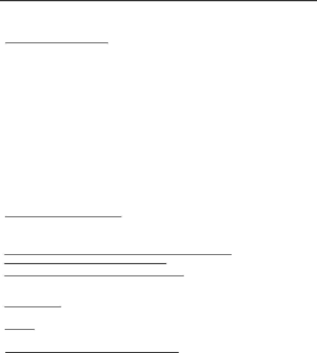
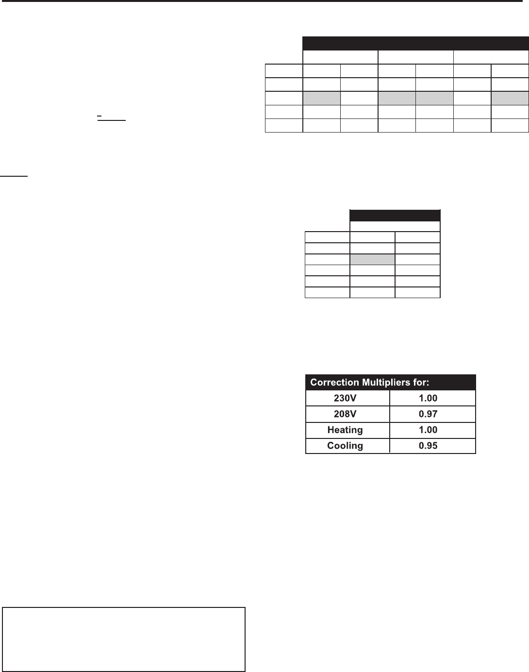
Determining the Indoor CFM: Chart A – CFM
Correct CFM (if needed):
Chart B – Correction Multipli
ers
Model
VEA12/VHA12 VEA18/VHA18VEA09/VHA09
ESP (")
.00"
.10"
.20"
.30”
Low
340
300
230
140
High
385
340
280
190
Low
420
350 *
290
250
High
470
420 **
350
300
Low
430
400
340
290
High
480
450
400
330
Highlighted values indicate rated performance point.
Rated performance for
* VEA12
Rated Performance for
** VHA12
ESP (") Low High
.00" 690 740
.10" 610 700
.20" 560 640
.30" 510 580
.40" 450 520
Model
VEA24/VHA24
Highlighted values indicate rated performance point.
IMPORTANT: FLEX DUCT CAN COLLAPSE AND
CAUSE AIRFLOW RESTRICTIONS. DO NOT
USE FLEX DUCT FOR: 90 DEGREE BENDS, OR
UNSUPPORTED RUNS OF 5 FT. OR MORE.
EXAMPLE: Measured voltage to unit (heaters) is 230 volts.
Measured Current Draw of strip heaters is 11.0 amps.
230 x 11.0 = 2530
2530/1000 = 2.53 Kilowatts
2.53 x 3413 = 8635
Supply Air 95°F
Return Air 75°F
Temperature Rise 20°
20 x 1.08 = 21.6
8635 = 400 CFM
21.6
CAPACITORS
ELECTRIC SHOCK HAZARD
WARNING
Turn off electric power before servicing.
Discharge capacitor with a 20,000 Ohm 2 Watt
resistor before handling.
Failure to do so may result in personal injury,
or death.
The capacitor analyzer will show whether the capacitor
is “open” or “shorted.” It will tell whether the capacitor
is within its micro farads rating and it will show whether
the capacitor is operating at the proper power-factor
percentage. The instrument will automatically discharge
the capacitor when the test switch is released.
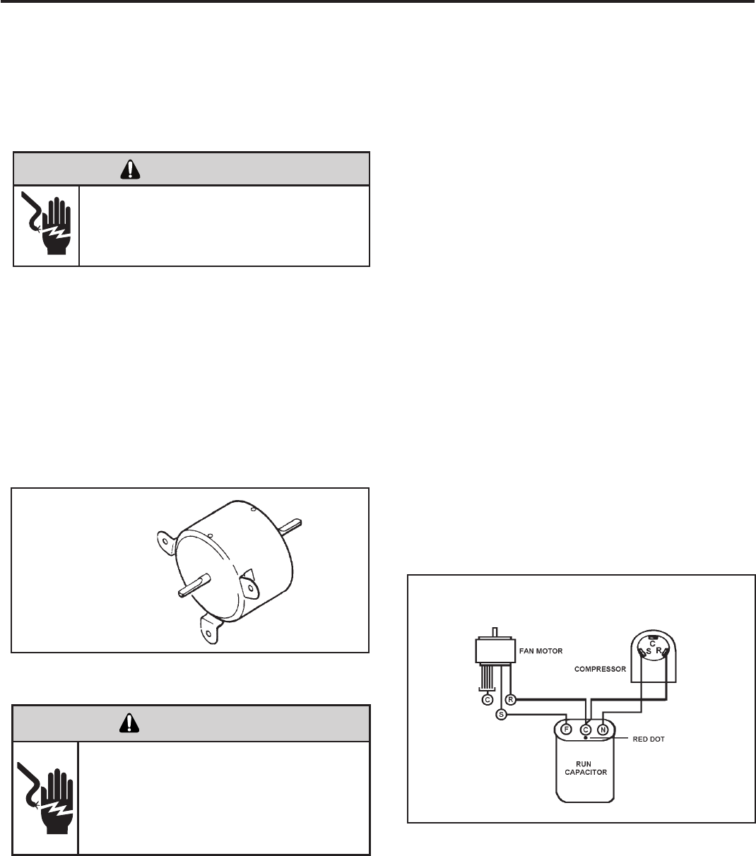
The starting winding of a motor can be damaged by a
shorted and grounded running capacitor. This damage
usually can be avoided by proper connection of the running
capacitor terminals.
From the supply line on a typical 230 volt circuit, a 115 volt
potential exists from the “R” terminal to ground through a
possible short in the capacitor. However, from the “S” or start
terminal, a much higher potential, possibly as high as 400
volts, exists because of the counter EMF generated in the
start winding. Therefore, the possibility of capacitor failure
is much greater when the identied terminal is connected
to the “S” or start terminal. The identied terminal should
always be connected to the supply line, or “R” terminal,
never to the “S” terminal.
When connected properly, a shorted or grounded running
capacitor will result in a direct short to ground from the “R”
terminal and will blow the line fuse. The motor protector
will protect the main winding from excessive temperature.
Dual Rated Run Capacitor Hook-up
22
BLOWER / FAN MOTOR TEST
Fan Motor
BLOWER / FAN MOTOR
A single phase permanent split capacitor motor is used to drive
the evaporator blower and condenser fan. A self-resetting
overload is located inside the motor to protect against high
temperature and high amperage conditions.
ELECTRIC SHOCK HAZARD
WARNING
Disconnect power to the unit before
servicing. Failure to follow this warning
could result in serious injury or death.
1. Do a visual inspection of motor’s wiring, housing etc.
Determine that the capacitor is serviceable.
2. Make sure the motor has cooled down.
3. Disconnect the fan motor wires from the control board.
4. Test for continuity between the windings also, test to
ground.
5. If any winding is open or grounded replace the motor.
6. A “live” test can also be performed by using a live test
probe (see appropriate wiring schematic).
Many motor capacitors are internally fused. Shorting the
terminals will blow the fuse, ruining the capacitor. A 20,000
ohm 2 watt resistor can be used to discharge capacitors
safely. Remove wires from capacitor and place resistor
across terminals. When checking a dual capacitor with
a capacitor analyzer or ohmmeter, both sides must be
tested.
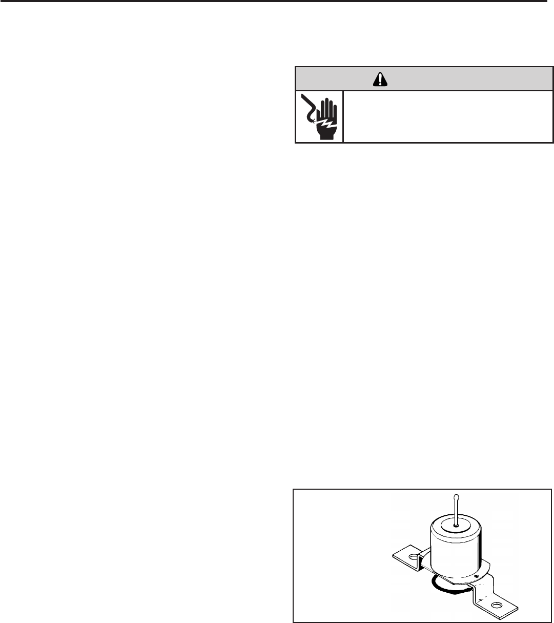
DRAIN PAN VALVE
During the cooling mode of operation, condensate which
collects in the drain pan is picked up by the condenser fan
blade and sprayed onto the condenser coil. This assists
in cooling the refrigerant plus evaporating the water.
During the heating mode of operation, it is necessary that
water be removed to prevent it from freezing during cold
outside temperatures. This could cause the condenser
fan blade to freeze in the accumulated water and prevent
it from turning.
To provide a means of draining this water, a bellows type
drain valve is installed over a drain opening in the base
pan.
This valve is temperature sensitive and will open when
the outside temperature reaches 40°F. The valve will
close gradually as the temperature rises above 40°F to
fully close at 60°F.
TESTING THE HEATING ELEMENTS AND
LIMIT SWITCHES
Testing of the heating elements can be made with an
ohmmeter or continuity tester across the terminals after
the power wires have been removed. Test the limit switch
for continuity across its input and output terminals.Test
below the limit switch’s reset temperature.
HEATER ELEMENTS AND LIMIT SWITCHES’
SPECIFICATIONS
All heat pumps and electric heat models are equipped
with a heating element and a limit switch (bimetal ther-
mostat). The limit is in series with the element and will
interrupt the power at a designed temperature.
Should the blower motor fail, lter become clogged or air-
ow be restricted etc., the high limit switch will open and
interrupt the power to the heater before reaching an un-
safe temperature condition.
VPAK 9K, 12K and 18K BTUs Models:
2.5 KW, 230 V, Resistance 18.61 Ohms + - 5%.
Has 1 Limit Switch, Opens at 120° F, Closes at 90° F,
It has a One Time Open Temp. of 145° F.
3.4 KW, 230 V, Resistance 13.68 Ohms + - 5%.
Has 1 Limit Switch, Opens at 120° F, Closes at 90° F,
It has a One Time Open Temp. of 145° F.
5 KW, 230 V, Resistance 9.31 Ohms + - 5%.
Has 1 Limit Switch, Opens at 130° F, Closes at 100° F,
It has a One Time Open Temp. of 155° F.
VPAK 24K BTUs Models:
2.5 KW, 230 V, Resistance 18.61 Ohms + - 5%.
Has 2 Limit Switches, Primary Opens at 155° F,
Closes at 125° F, Secondary’s Open Temp. is 200° F.
3.4 KW, 230 V, Resistance 13.68 Ohms + - 5%.
Has 2 Limit Switches, Primary Opens at 155° F,
Closes at 125° F, Secondary’s Open Temp. is 200° F.
5 KW, 230 V, Resistance 9.31 Ohms + - 5%.
Has 2 Limit Switches, Primary Opens at 155° F,
Closes at 125° F, Secondary’s Open Temp. is 200° F.
7.5 KW, 230 V (composed of 2, 3.7 KW Elements)
Each Has a Resistance of 12.41 Ohms + - 5%.
Each Has 2 Limit Switches, Primary Opens at 165° F,
Closes at 135° F With a 1 time Open Temp. of 210° F.
Secondary Limit’s Open Temp. is 200° F.
10 KW, 230 V (composed of 2, 5 KW Elements)
Each Has a Resistance of 9.31 Ohms + - 5%.
Each Has 2 Limit Switches, Primary Opens at 165° F,
Closes at 135° F With a 1 time Open Temp. of 210° F.
Secondary Limit’s Open Temp. is 200° F.
NOTE: Always replace with an exact replacement.
Bellows Assembly
Drain Pan Valve
ELECTRIC SHOCK HAZARD
WARNING
Disconnect power to the unit before
servicing. Failure to follow this warning
could result in serious injury or death.
23
A good understanding of the basic operation of the
refrigeration system is essential for the service technician.
Without this understanding, accurate troubleshooting of
refrigeration system problems will be more difcult and time
consuming, if not (in some cases) entirely impossible. The
refrigeration system uses four basic principles (laws) in its
operation they are as follows:
1. “Heat always ows from a warmer body to a cooler
body.”
2. “Heat must be added to or removed from a substance
before a change in state can occur”
3. “Flow is always from a higher pressure area to a lower
pressure area.”
4. “The temperature at which a liquid or gas changes state
is dependent upon the pressure.”
The refrigeration cycle begins at the compressor. Starting
the compressor creates a low pressure in the suction line
which draws refrigerant gas (vapor) into the compressor.
The compressor then “compresses” this refrigerant, raising
its pressure and its (heat intensity) temperature.
The refrigerant leaves the compressor through the discharge
Line as a hot High pressure gas (vapor). The refrigerant
enters the condenser coil where it gives up some of its
heat. The condenser fan moving air across the coil’s nned
surface facilitates the transfer of heat from the refrigerant to
the relatively cooler outdoor air.
When a sufcient quantity of heat has been removed from
the refrigerant gas (vapor), the refrigerant will “condense”
(i.e. change to a liquid). Once the refrigerant has been
condensed (changed) to a liquid it is cooled even further by
the air that continues to ow across the condenser coil.
The VPAK design determines at exactly what point (in
the condenser) the change of state (i.e. gas to a liquid)
takes place. In all cases, however, the refrigerant must be
totally condensed (changed) to a Liquid before leaving the
condenser coil.
The refrigerant leaves the condenser Coil through the liquid
line as a warm high pressure liquid. It next will pass through
the refrigerant drier (if so equipped). It is the function of the
drier to trap any moisture present in the system, contaminants,
and large particulate matter.
The liquid refrigerant next enters the metering device. The
metering device is a capillary tube. The purpose of the
metering device is to “meter” (i.e. control or measure) the
quantity of refrigerant entering the evaporator coil.
In the case of the capillary tube this is accomplished (by
design) through size (and length) of device, and the pressure
difference present across the device.
Since the evaporator coil is under a lower pressure (due to
the suction created by the compressor) than the liquid line,
the liquid refrigerant leaves the metering device entering the
evaporator coil. As it enters the evaporator coil, the larger
area and lower pressure allows the refrigerant to expand
and lower its temperature (heat intensity). This expansion is
often referred to as “boiling”. Since the unit’s blower is moving
indoor air across the nned surface of the evaporator coil,
the expanding refrigerant absorbs some of that heat. This
results in a lowering of the indoor air temperature, hence the
“cooling” effect.
The expansion and absorbing of heat cause the liquid
refrigerant to evaporate (i.e. change to a gas). Once the
refrigerant has been evaporated (changed to a gas), it is
heated even further by the air that continues to ow across
the evaporator coil.
The particular system design determines at exactly what
point (in the evaporator) the change of state (i.e. liquid to a
gas) takes place. In all cases, however, the refrigerant must
be totally evaporated (changed) to a gas before leaving the
evaporator coil.
The low pressure (suction) created by the compressor
causes the refrigerant to leave the evaporator through the
suction line as a cool low pressure vapor. The refrigerant then
returns to the compressor, where the cycle is repeated.
24
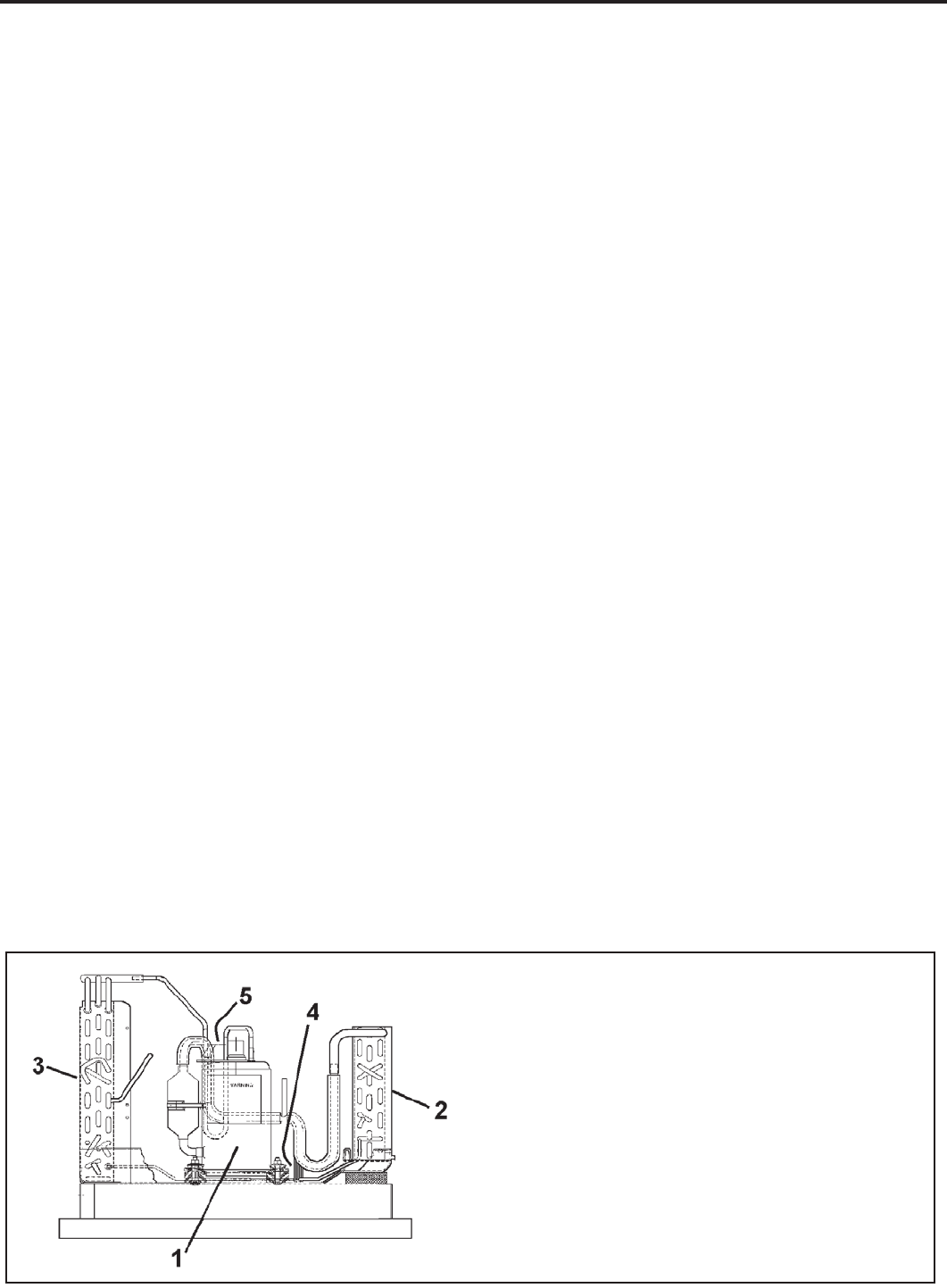
1. Compressor
2. Evaporator Coil Assembly
3. Condenser Coil Assembly
4. Capillary Tube
5. Compressor Overload
Refrigeration Assembly
CUT/SEVER HAZARD
WARNING
Be careful with the sharp edges and corners.
Wear protective clothing and gloves, etc.
Failure to do so could result in serious injury.
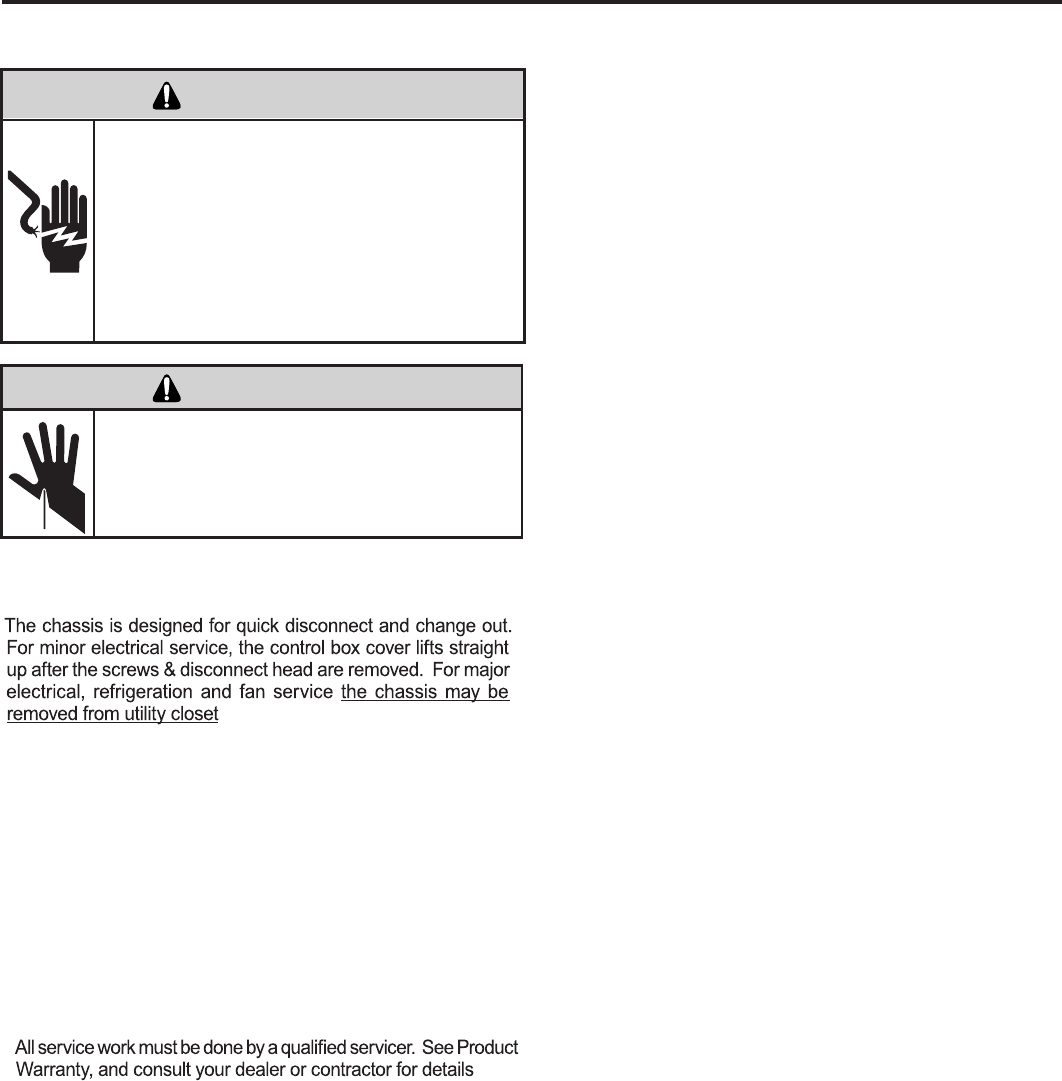
ELECTRIC SHOCK HAZARD
WARNING
Turn off electric power before service or
installation.
Extreme care must be used, if it becomes
necessary to work on equipment with power
applied.
Failure to do so could result in serious injury or
death.
Servicing / Chassis Quick Changeouts
.
Warranty
To Remove the Chassis from the Closet:
A. Switch the wall Thermostat off.
B. Pull the Power Disconnect located in the front of the chassis.
C. Disconnect the power coming into the unit from the main
breaker panel or the closet mounted disconnect.
D. Disconnect the electrical connection.
E. Disconnect the duct work.
F. Slide the chassis out of the wall plenum.
G. Lift the chassis out of the utility closet.
25
Proper refrigerant charge is essential to proper unit opera-
tion. Operating a unit with an improper refrigerant charge will
result in reduced performance (capacity) and/or efciency.
Accordingly, the use of proper charging methods during ser-
vicing will insure that the unit is functioning as designed and
that its compressor will not be damaged.
Too much refrigerant (overcharge) in the system is just as bad
(if not worse) than not enough refrigerant (undercharge). They
both can be the source of certain compressor failures if they
remain uncorrected for any period of time. Quite often, other
problems (such as low air ow across evaporator, etc.) are
misdiagnosed as refrigerant charge problems. The refrigerant
circuit diagnosis chart will assist you in properly diagnosing
these systems.
An overcharged unit will at times return liquid refrigerant
(slugging) back to the suction side of the compressor eventually
causing a mechanical failure within the compressor. This
mechanical failure can manifest itself as valve failure, bearing
failure, and/or other mechanical failure. The specic type of
failure will be inuenced by the amount of liquid being returned,
and the length of time the slugging continues.
Not enough refrigerant (undercharge) on the other hand, will
cause the temperature of the suction gas to increase to the point
where it does not provide sufcient cooling for the compressor
motor. When this occurs, the motor winding temperature will
increase causing the motor to overheat and possibly cycle open
the compressor overload protector. Continued overheating of
the motor windings and/or cycling of the overload will eventually
lead to compressor motor or overload failure.
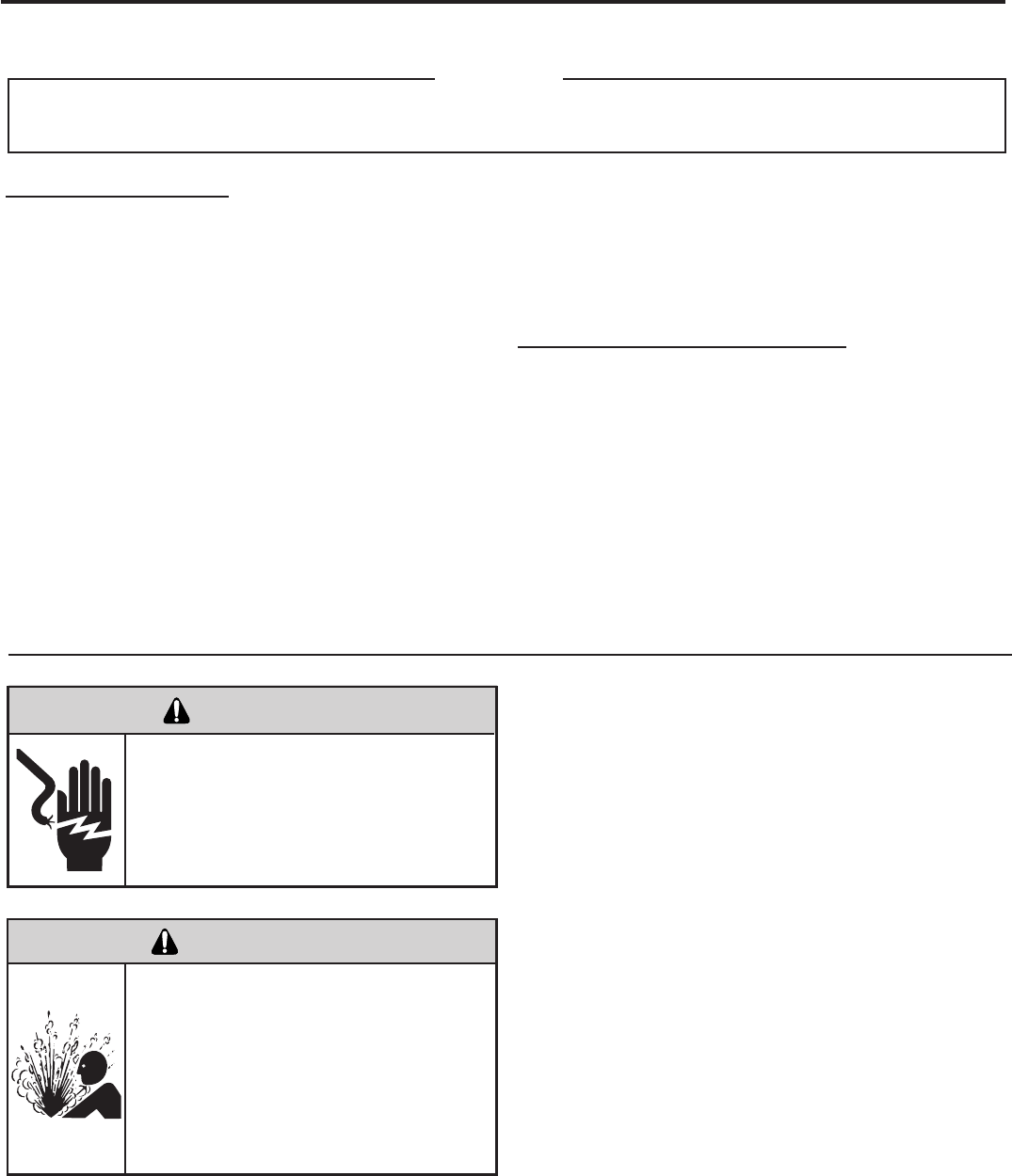
Unplug and/or disconnect all electrical power
to the unit before performing inspections,
maintenances or service.
Failure to do so could result in electric shock,
serious injury or death.
Sealed Refrigeration System contains refrigerant
and oil under high pressure.
Proper safety procedures must be followed,
and proper protective clothing must be worn
when working with refrigerants.
Failure to follow these procedures could
result in serious injury or death.
WARNING
WARNING
RISK OF ELECTRIC SHOCK
HIGH PRESSURE HAZARD
ANY SEALED SYSTEM REPAIRS TO COOL-ONLY MODELS REQUIRE THE INSTALLATION OF A LIQUID LINE DRIER.
ALSO, ANY SEALED SYSTEM REPAIRS TO HEAT PUMP MODELS REQUIRE THE INSTALLATION OF A SUCTION LINE DRIER.
IMPORTANT
EQUIPMENT REQUIRED:
1. Voltmeter
2. Ammeter
3. Ohmmeter
4. E.P.A. Approved Refrigerant Recovery System
5. Vacuum Pump (capable of 200 microns or less
vacuum.)
6. Acetylene Welder
7. Electronic Halogen Leak Detector (G.E. Type H-6 or
equivalent.)
8. Accurate refrigerant charge measuring device such
as:
a. Balance Scales - 1/2 oz. accuracy
b. Charging Board - 1/2 oz. accuracy
9. High Pressure Gauge - (0 - 400 lbs.)
10. Low Pressure Gauge - (30 - 150 lbs.)
11. Vacuum Gauge - (0 - 1000 microns)
EQUIPMENT MUST BE CAPABLE OF:
1. Recovery CFC’s as low as 5%.
2. Evacuation from both the high side and low side of the
system simultaneously.
3. Introducing refrigerant charge into high side of the
system.
4. Accurately weighing the refrigerant charge actually
introduced into the system.
5. Facilities for owing nitrogen through refrigeration tubing
during all brazing processes.
26
3. Install a process tube to sealed system.
4. Make necessary repairs to system.
5. Evacuate system to 200 microns or less.
6. Weigh in refrigerant with the property quantity of R-22
refrigerant.
7. Start unit, and verify performance.
8. Crimp the process tube and solder the end shut.
Proper safety procedures must be followed,
and proper protective clothing must be worn
when working with a torch.
Failure to follow these procedures could
result in moderate or serious injury.
Proper safety procedures must be followed,
and proper protective clothing must be worn
when working with liquid refrigerant.
Failure to follow these procedures could
result in minor to moderate injury.
WARNING
CAUTION
BURN HAZARD
FREEZE HAZARD
Proper safety procedures must be followed,
and proper protective clothing must be worn
when working with a torch.
Failure to follow these procedures could
result in moderate or serious injury.
WARNING
BURN HAZARD
The acceptable method for charging the RAC system is the
Weighed in Charge Method. The weighed in charge method is
applicable to all units. It is the preferred method to use, as it is
the most accurate.
The weighed in method should always be used whenever
a charge is removed from a unit such as for a leak repair,
compressor replacement, or when there is no refrigerant
charge left in the unit. To charge by this method, requires the
following steps:
1. Install a piercing valve to remove refrigerant from the
sealedsystem. (Piercing valve must be removed from the
system before recharging.)
2. Recover Refrigerant in accordance with EPA regulations.
27
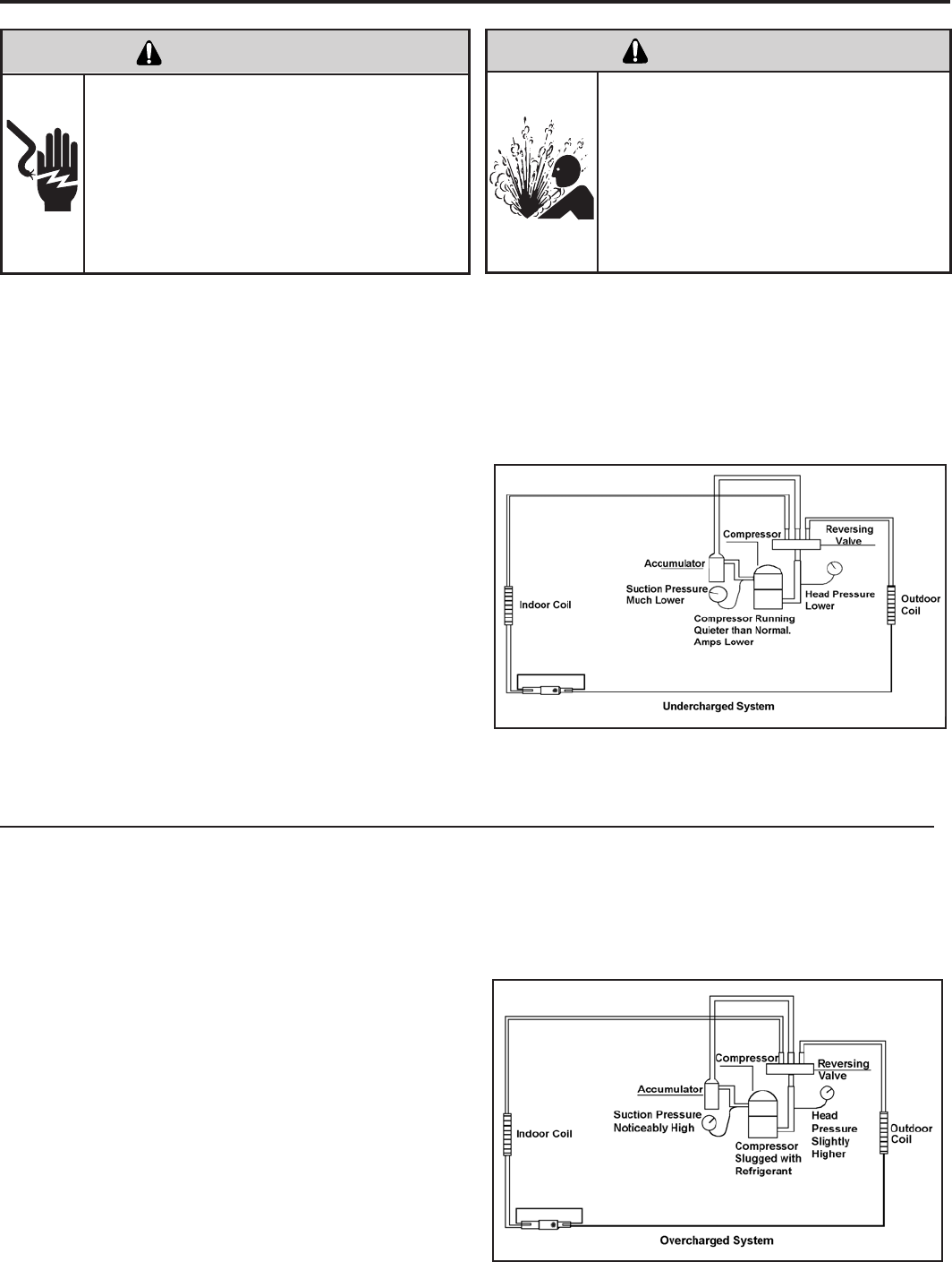
An undercharged system will result in poor performance
(low pressures, etc.) in both the heating and cooling
cycle.
Whenever you service a unit with an undercharge of
refrigerant, always suspect a leak. The leak must be
repaired before charging the unit.
To check for an undercharged system, turn the unit on,
allow the compressor to run long enough to establish
working pressures in the system (15 to 20 minutes).
During the cooling cycle you can listen carefully at the exit
of the metering device into the evaporator; an intermittent
hissing and gurgling sound indicates a low refrigerant
charge. Intermittent frosting and thawing of the evaporator
is another indication of a low charge, however, frosting
and thawing can also be caused by insufcient air over
the evaporator.
Checks for an undercharged system can be made at
the compressor. If the compressor seems quieter than
normal, it is an indication of a low refrigerant charge.
A check of the amperage drawn by the compressor
motor should show a lower reading. (Check the Unit
Specication.) After the unit has run 10 to 15 minutes,
check the gauge pressures. Gauges connected to system
with an undercharge will have low head pressures and
substantially low suction pressures.
of the evaporator will not be encountered because the
refrigerant will boil later if at all. Gauges connected to
system will usually have higher head pressure (depending
upon amount of over charge). Suction pressure should be
slightly higher.
Compressor amps will be near normal or higher.
Noncondensables can also cause these symptoms. To
conrm, remove some of the charge, if conditions improve,
system may be overcharged. If conditions don’t improve,
Noncondensables are indicated.
Whenever an overcharged system is indicated, always
make sure that the problem is not caused by air ow
problems. Improper air ow over the evaporator coil may
indicate some of the same symptoms as an over charged
system.
An overcharge can cause the compressor to fail, since it
would be “slugged” with liquid refrigerant.
The charge for any system is critical. When the compressor
is noisy, suspect an overcharge, when you are sure that
the air quantity over the evaporator coil is correct. Icing
ELECTRIC SHOCK HAZARD
WARNING
Turn off electric power before service or
installation.
Extreme care must be used, if it becomes
necessary to work on equipment with power
applied.
Failure to do so could result in serious injury or
death.
Sealed Refrigeration System contains refrigerant
and oil under high pressure.
Proper safety procedures must be followed,
and proper protective clothing must be worn
when working with refrigerants.
Failure to follow these procedures could
result in serious injury or death.
WARNING
HIGH PRESSURE HAZARD
28
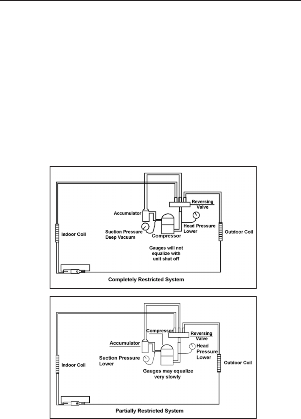
Troubleshooting a restricted refrigerant system can be
difcult. The following procedures are the more common
problems and solutions to these problems. There are two
types of refrigerant restrictions: Partial restrictions and
complete restrictions.
A partial restriction allows some of the refrigerant to
circulate through the system.
With a complete restriction there is no circulation of
refrigerant in the system.
Restricted refrigerant systems display the same symptoms
as a “low-charge condition.”
When the unit is shut off, the gauges may equalize very
slowly.
Gauges connected to a completely restricted system will
run in a deep vacuum. When the unit is shut off, the gauges
will not equalize at all.
A quick check for either condition begins at the evaporator.
With a partial restriction, there may be gurgling sounds
at the metering device entrance to the evaporator. The
evaporator in a partial restriction could be partially frosted
or have an ice ball close to the entrance of the metering
device. Frost may continue on the suction line back to the
compressor.
Often a partial restriction of any type can be found by feel,
as there is a temperature difference from one side of the
restriction to the other.
With a complete restriction, there will be no sound at the
metering device entrance. An amperage check of the
compressor with a partial restriction may show normal
current when compared to the unit speci cation. With a
complete restriction the current drawn may be considerably
less than normal, as the compressor is running in a deep
vacuum (no load.) Much of the area of the condenser will
be relatively cool since most or all of the liquid refrigerant
will be stored there.
The following conditions are based primarily on a system
in the cooling mode.
29
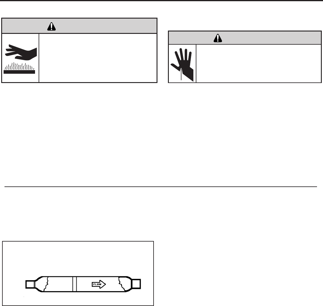
30
All units are equipped with capillary tube metering
devices.
Checking for restricted capillary tubes.
1. Connect pressure gauges to unit.
2. Start the unit in the cooling mode. If after a few minutes
of operation the pressures are normal, the check valve
and the cooling capillary are not restricted.
3. Switch the unit to the heating mode and observe the
gauge readings after a few minutes running time. If
the system pressure is lower than normal, the heating
capillary is restricted.
4. If the operating pressures are lower than normal in both
the heating and cooling mode, the cooling capillary is
restricted.
Proper safety procedures must be followed,
and proper protective clothing must be worn
when working with a torch.
Failure to follow these procedures could
result in moderate or serious injury.
WARNING
BURN HAZARD
One-way Check Valve
(Heat Pump Models)
A unique two-way check valve is used on the reverse cycle
heat pumps. It is pressure operated and used to direct the
ow of refrigerant through a single lter drier and to the
proper capillary tube during either the heating or cooling
cycle.
NOTE: The slide (check) inside the valve is made of teon.
Should it become necessary to replace the check valve,
place a wet cloth around the valve to prevent overheating
during the brazing operation.
CHECK VALVE OPERATION
In the cooling mode of operation, high pressure liquid enters
the check valve forcing the slide to close the opposite port
(liquid line) to the indoor coil. Refer to refrigerant ow chart.
This directs the refrigerant through the lter drier and cooling
capillary tube to the indoor coil.
In the heating mode of operation, high pressure refrigerant
enters the check valve from the opposite direction, closing
the port (liquid line) to the outdoor coil. The ow path of the
refrigerant is then through the lter drier and heating capillary
to the outdoor coil.
Failure of the slide in the check valve to seat properly in
either mode of operation will cause ooding of the cooling
coil. This is due to the refrigerant bypassing the heating or
cooling capillary tube and entering the liquid line.
COOLING MODE
In the cooling mode of operation, liquid refrigerant from
condenser (liquid line) enters the cooling check valve
forcing the heating check valve shut. The liquid refrigerant
is directed into the liquid dryer after which the refrigerant
is metered through cooling capillary tubes to evaporator.
(Note: liquid refrigerant will also be directed through the
heating capillary tubes in a continuous loop during the
cooling mode).
HEATING MODE
In the heating mode of operation, liquid refrigerant from
the indoor coil enters the heating check valve forcing the
cooling check valve shut. The liquid refrigerant is directed
into the liquid dryer after which the refrigerant is metered
through the heating capillary tubes to outdoor coils. (Note:
liquid refrigerant will also be directed through the cooling
capillary tubes in a continuous loop during the heating
mode).
CUT/SEVER HAZARD
WARNING
Be careful with the sharp edges and corners.
Wear protective clothing and gloves, etc.
Failure to do so could result in serious injury.
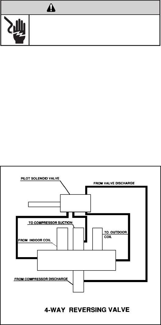
31
NOTE: System operating pressures must be near
normal before valve can shift.
The Reversing Valve controls the direction of refrigerant ow
to the indoor and outdoor coils. It consists of a pressure-
operated, main valve and a pilot valve actuated by a solenoid
plunger. The solenoid is energized during the heating cycle
only. The reversing valves used in the VPAK system is a
2-position, 4-way valve.
The single tube on one side of the main valve body is the
high-pressure inlet to the valve from the compressor. The
center tube on the opposite side is connected to the low
pressure (suction) side of the system. The other two are
connected to the indoor and outdoor coils. Small capillary
tubes connect each end of the main valve cylinder to the
“A” and “B” ports of the pilot valve. A third capillary is a common
return line from these ports to the suction tube on the main
valve body. Four-way reversing valves also have a capillary
tube from the compressor discharge tube to the pilot valve.
The piston assembly in the main valve can only be shifted
by the pressure differential between the high and low sides
of the system. The pilot section of the valve opens and
closes ports for the small capillary tubes to the main valve
to cause it to shift.
ELECTRIC SHOCK HAZARD
WARNING
Disconnect power to the unit before servicing.
Failure to follow this warning could result in
serious injury or death.
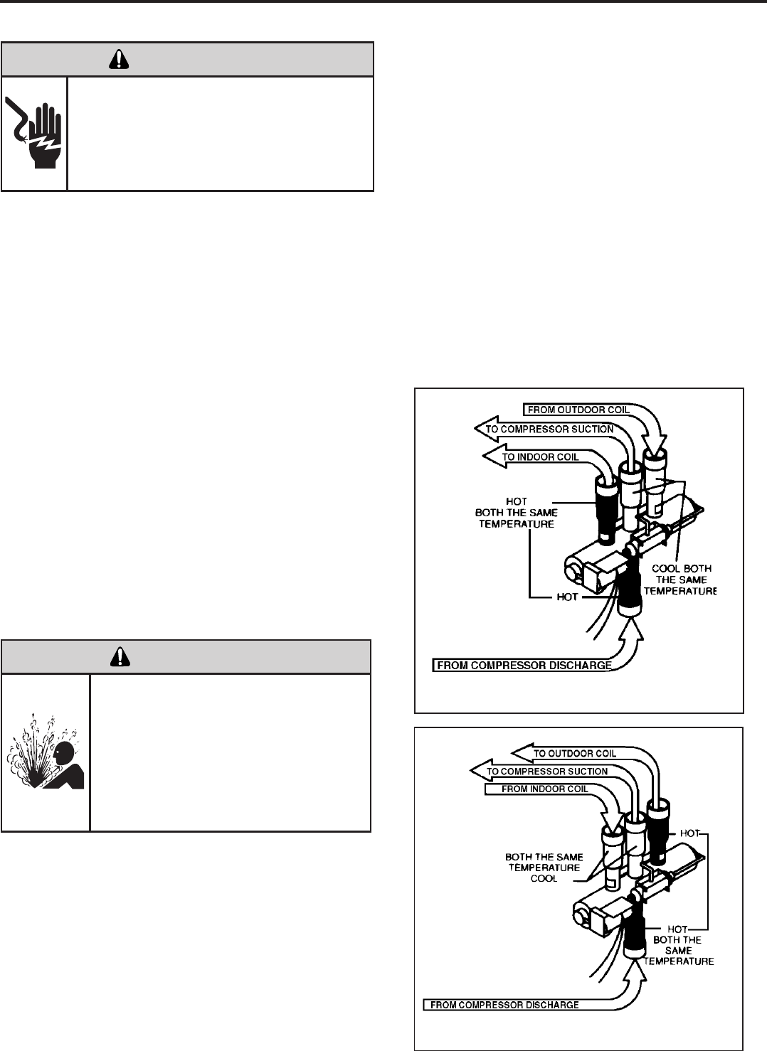
32
Reversing Valve in Heating Mode
The solenoid coil is an electromagnetic type coil mounted
on the reversing valve and is energized during the
operation of the compressor in the heating cycle.
1. Turn off high voltage electrical power to unit.
2. Unplug line voltage lead from reversing valve coil.
3. Check for electrical continuity through the coil. If you
do not have continuity replace the coil.
4. Check from each lead of coil to the copper liquid line
as it leaves the unit or the ground lug. There should
be no continuity between either of the coil leads
and ground; if there is, coil is grounded and must be
replaced.
5. If coil tests okay, reconnect the electrical leads.
6. Make sure coil has been assembled correctly.
NOTE: Do not start unit with solenoid coil removed from
valve, or do not remove coil after unit is in operation. This
will cause the coil to burn out.
NOTE: You must have normal operating pressures before
the reversing valve can shift.
Check the operation of the valve by starting the system
and switching the operation from “Cooling” to “Heating”
and then back to “Cooling”. Do not hammer on valve.
Occasionally, the reversing valve may stick in the heating
or cooling position or in the mid-position.
When sluggish or stuck in the mid-position, part of the
discharge gas from the compressor is directed back to the
suction side, resulting in excessively high suction pressure.
Should the valve fail to shift from coooling to heating, block
the air ow through the outdoor coil and allow the discharge Reversing Valve in Cooling Mode
ELECTRIC SHOCK HAZARD
WARNING
Unplug and/or disconnect all electrical power
to the unit before performing inspections,
maintenances or service.
Failure to do so could result in electric shock,
serious injury or death.
Sealed Refrigeration System contains refrigerant
and oil under high pressure.
Proper safety procedures must be followed,
and proper protective clothing must be worn
when working with refrigerants.
Failure to follow these procedures could
result in serious injury or death.
WARNING
HIGH PRESSURE HAZARD
pressure to build in the system. Then switch the system
from heating to cooling.
If the valve is stuck in the heating position, block the air
ow through the indoor coil and allow discharge pressure
to build in the system. Then switch the system from
heating to cooling.
Should the valve fail to shift in either position after
increasing the discharge pressure, replace the valve.
Dented or damaged valve body or capillary tubes can
prevent the main slide in the valve body from shifting.
If you determing this is the problem, replace the reversing
valve.
After all of the previous inspections and checks have
been made and determined correct, then perform the
“Touch Test” on the reversing valve.
33
8. Pressurize sealed system with a combination of R-22
and nitrogen and check for leaks, using a suitable leak
detector. Recover refrigerant per EPA guidelines.
9. Once the sealed system is leak free, install solenoid coil
on new valve and charge the sealed system by weighing
in the proper amount and type of refrigerant as shown
on rating plate. Crimp the process tubes and solder the
ends shut. Do not leave Schrader or piercing valves in
the sealed system.
NOTE: When brazing a reversing valve into the system, it is
of extreme importance that the temperature of the valve does
not exceed 250°F at any time.
Wrap the reversing valve with a large rag saturated with
water. “Re-wet” the rag and thoroughly cool the valve after
each brazing operation of the four joints involved.
The wet rag around the reversing valve will eliminate
conduction of heat to the valve body when brazing the line
connection.
6. Protect new valve body from heat while brazing with plastic
heat sink (Thermo Trap) or wrap valve body with wet
rag.
7. Fit all lines into new valve and braze lines into new
valve.
1. Install Process Tubes. Recover refrigerant from sealed
system. PROPER HANDLING OF RECOVERED
REFRIGERANT ACCORDING TO EPA REGULATIONS
IS REQUIRED.
2. Remove solenoid coil from reversing valve. If coil is to
be reused, protect from heat while changing valve.
3. Unbraze all lines from reversing valve.
4. Clean all excess braze from all tubing so that they will
slip into ttings on new valve.
5. Remove solenoid coil from new valve.
The use of a torch requires extreme care and proper
judgment. Follow all safety recommended precautions
and protect surrounding areas with re proof materials.
Have a re extinguisher readily available. Failure to follow
this notice could result in moderate to serious property
damage.
NOTICE
FIRE HAZARD
The only definite indications that the slide is in the mid-
position is if all three tubes on the suction side of the valve
are hot after a few minutes of running time.
NOTE: A condition other than those illustrated above, and
on Page 31, indicate that the reversing valve is not shifting
properly. Both tubes shown as hot or cool must be the same
corresponding temperature.
Certain unit components operate at
temperatures hot enough to cause burns.
Proper safety procedures must be followed,
and proper protective clothing must be
worn.
Failure to follow these procedures could
result in minor to moderate injury.
WARNING
BURN HAZARD
Sealed Refrigeration System contains refrigerant
and oil under high pressure.
Proper safety procedures must be followed,
and proper protective clothing must be worn
when working with refrigerants.
Failure to follow these procedures could
result in serious injury or death.
WARNING
HIGH PRESSURE HAZARD
The use of nitrogen requires a pressure
regulator. Follow all safety procedures and
wear protective safety clothing etc.
Failure to follow proper safety procedures
could result in serious injury or death.
WARNING
EXPLOSION HAZARD
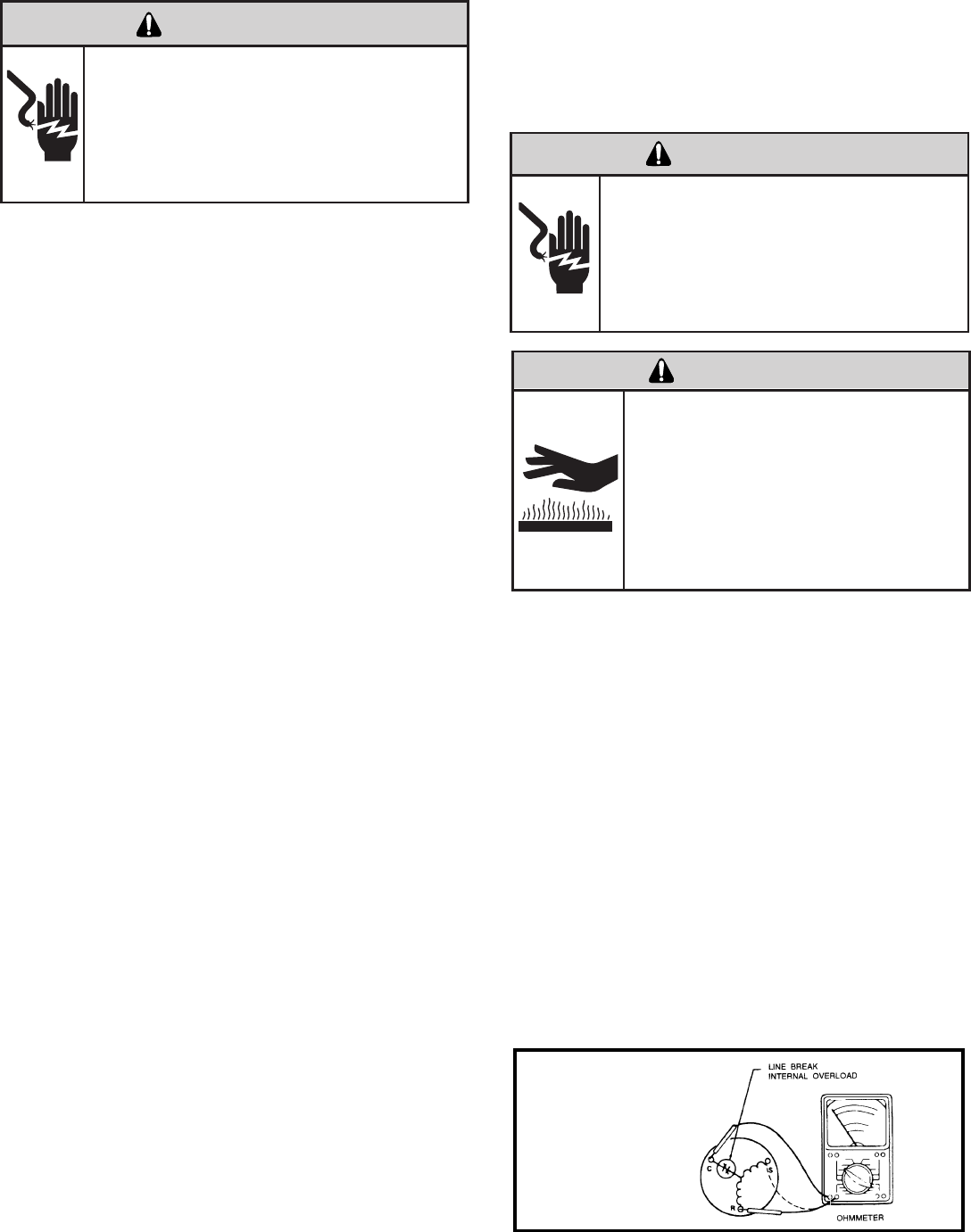
34
Locked rotor voltage (L.R.V.) is the actual voltage available
at the compressor under a stalled condition.
Disconnect power from unit. Using a voltmeter, attach one
lead of the meter to the run “R” terminal on the compressor
and the other lead to the common “C” terminal of the com-
pressor. Restore power to unit.
Start the compressor with the volt meter attached; then stop
the unit. Attempt to restart the compressor within a couple
of seconds and immediately read the voltage on the meter.
The compressor under these conditions will not start and will
usually kick out on overload within a few seconds since the
pressures in the system will not have had time to equalize.
Voltage should be at or above minimum voltage of 197 VAC,
as specied on the rating plate. If less than minimum, check
for cause of inadequate power supply; i.e., incorrect wire
size, loose electrical connections, etc.
ELECTRIC SHOCK HAZARD
WARNING
Turn off electric power before service or
installation. Extreme care must be used, if it
becomes necessary to work on equipment with
power applied.
Failure to do so could result in serious injury or
death.
Heat generated within the compressor shell, usually due
to recycling of the motor, is slow to dissipate. It may take
anywhere from a few minutes to several hours for the
overload to reset.
With power off, remove the leads from compressor termi-
nals. If the compressor is hot, allow the overload to cool
before starting check. Using an ohmmeter, test continu-
ity across the terminals of the external overload. If you
do not have continuity; this indicates that the overload is
open and must be replaced.
The overload is embedded in the motor windings to
sense the winding temperature and/or current draw. The
overload is connected in series with the common motor
terminal.
1. With no power to unit, remove the leads from the com-
pressor terminals. Allow motor to cool.
2. Using an ohmmeter, test continuity between terminals
C-S and C-R. If no continuity, the compressor overload is
open and the compressor must be replaced.
The running amperage of the compressor is the most impor-
tant of these readings. A running amperage higher than that
indicated in the performance data indicates that a problem
exists mechanically or electrically.
Single Phase Running and L.R.A. Test
NOTE: Consult the specication and performance section
for running amperage. The L.R.A. can also be found on the
rating plate.
Select the proper amperage scale and clamp the meter
probe around the wire to the “C” terminal of the compressor.
Turn on the unit and read the running amperage on the me-
ter. If the compressor does not start, the reading will indicate
the locked rotor amperage (L.R.A.).
The compressor is equipped with an external or internal
overload which senses both motor amperage and wind-
ing temperature. High motor temperature or amperage
heats the overload causing it to open, breaking the com-
mon circuit within the compressor.
Certain unit components operate at
temperatures hot enough to cause burns.
Proper safety procedures must be followed,
and proper protective clothing must be
worn.
Failure to follow this warning could result
in moderate to serious injury.
WARNING
BURN HAZARD
ELECTRIC SHOCK HAZARD
WARNING
Turn off electric power before service or
installation. Extreme care must be used, if it
becomes necessary to work on equipment
with power applied.
Failure to do so could result in serious injury or
death.
Internal Overload
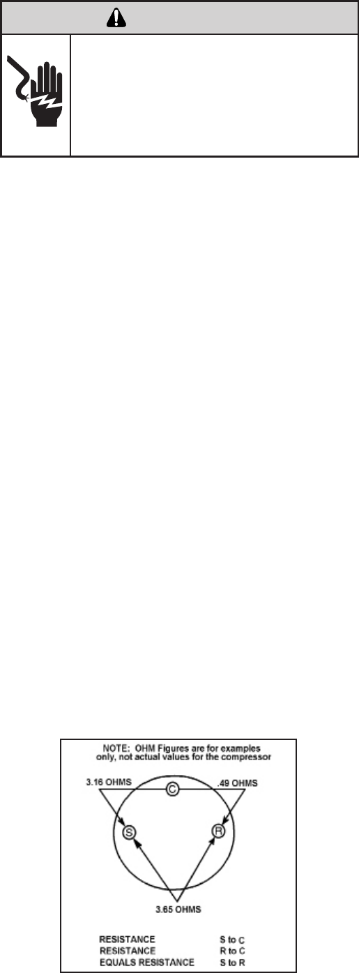
35
Remove the leads from the compressor terminals and set
the ohmmeter on the lowest scale (R x 1).
Touch the leads of the ohmmeter from terminals common
to start (“C” to “S”). Next, touch the leads of the ohmmeter
from terminals common to run (“C” to “R”).
Add values “C” to “S” and “C” to “R” together and
check resistance from start to run terminals (“S” to “R”).
Resistance “S” to “R” should equal the total of “C” to “S”
and “C” to “R.”
In a single phase PSC compressor motor, the highest
value will be from the start to the run connections (“S” to
“R”). The next highest resistance is from the start to the
common connections (“S” to “C”). The lowest resistance
is from the run to common. (“C” to “R”) Before replacing a
compressor, check to be sure it is defective.
GROUND TEST
Use an ohmmeter set on its highest scale. Touch one
lead to the compressor body (clean point of contact as
a good connection is a must) and the other probe in turn
to each compressor terminal. If a reading is obtained the
compressor is grounded and must be replaced.
Check the complete electrical system to the compressor
and compressor internal electrical system, check to be
certain that compressor is not out on internal overload.
Complete evaluation of the system must be made
whenever you suspect the compressor is defective. If
the compressor has been operating for sometime, a
careful examination must be made to determine why the
compressor failed.
Many compressor failures are caused by the following
conditions:
1. Improper air ow over the evaporator.
2. Overcharged refrigerant system causing liquid to be
returned to the compressor.
3. Restricted refrigerant system.
4. Lack of lubrication.
5. Liquid refrigerant returning to compressor causing oil
to be washed out of bearings.
6. Noncondensables such as air and moisture in
the system. Moisture is extremely destructive to a
refrigerant system.
7. Capacitor test (see page 21).
CHECKING COMPRESSOR EFFICIENCY
The reason for compressor inefciency is normally due
to broken or damaged suction and/or discharge valves,
reducing the ability of the compressor to pump refrigerant
gas.
This condition can be checked as follows:
1. Install a piercing valve on the suction and discharge or
liquid process tube.
2. Attach gauges to the high and low sides of the system.
3. Start the system and run a “cooling or heating perfor-
mance test.” If test shows:
A. Below normal high side pressure
B. Above normal low side pressure
C. Low temperature difference across coil
The compressor valves are faulty - replace the
compressor.
ELECTRIC SHOCK HAZARD
WARNING
Turn off electric power before service or
installation. Extreme care must be used, if it
becomes necessary to work on equipment
with power applied.
Failure to do so could result in serious injury or
death.
36
1. Be certain to perform all necessary electrical and
refrigeration tests to be sure the compressor is
actually defective before replacing.
2. Recover all refrigerant from the system though
the process tubes. PROPER HANDLING OF
RECOVERED REFRIGERANT ACCORDING TO
EPA REGULATIONS IS REQUIRED. Do not use
gauge manifold for this purpose if there has been
a burnout. You will contaminate your manifold and
hoses. Use a Schrader valve adapter and copper
tubing for burnout failures.
3. After all refrigerant has been recovered, disconnect
suction and discharge lines from the compressor and
remove compressor. Be certain to have both suction
and discharge process tubes open to atmosphere.
4. Carefully pour a small amount of oil from the suction
stub of the defective compressor into a clean
container.
9. Evacuate the system with a good vacuum pump capable
of a nal vacuum of 300 microns or less. The system
should be evacuated through both liquid line and suction
line gauge ports. While the unit is being evacuated, seal
all openings on the defective compressor. Compressor
manufacturers will void warranties on units received not
properly sealed. Do not distort the manufacturers tube
connections.
10. Recharge the system with the correct amount of
refrigerant. The proper refrigerant charge will be
found on the unit rating plate. The use of an accurate
measuring device, such as a charging cylinder,
electronic scales or similar device is necessary.
5. Using an acid test kit (one shot or conventional kit), test
the oil for acid content according to the instructions
with the kit.
6. If any evidence of a burnout is found, no matter how
slight, the system will need to be cleaned up following
proper procedures.
7. Install the replacement compressor.
8. Pressurize with a combination of R-22 and nitrogen
and leak test all connections with an electronic or
Halide leak detector. Recover refrigerant and repair
any leaks found.
Repeat Step 8 to insure no more leaks are present.
Unplug and/or disconnect all electrical power
to the unit before performing inspections,
maintenances or service.
Failure to do so could result in electric shock,
serious injury or death.
WARNING
RISK OF ELECTRIC SHOCK
Sealed Refrigeration System contains refrigerant
and oil under high pressure.
Proper safety procedures must be followed,
and proper protective clothing must be worn
when working with refrigerants.
Failure to follow these procedures could
result in serious injury or death.
WARNING
HIGH PRESSURE HAZARD
Extreme care, proper judgment and all safety
procedures must be followed when testing,
troubleshooting, handling or working around
unit while in operation with high temperature
components. Wear protective safety aids
such as: gloves, clothing etc.
Failure to do so could result in serious burn
injury.
WARNING
HIGH TEMPERATURES
The use of a torch requires extreme care and proper
judgment. Follow all safety recommended precautions
and protect surrounding areas with re proof materials.
Have a re extinguisher readily available. Failure to follow
this notice could result in moderate to serious property
damage.
NOTICE
FIRE HAZARD
The use of nitrogen requires a pressure
regulator. Follow all safety procedures and
wear protective safety clothing etc.
Failure to follow proper safety procedures
result in serious injury or death.
WARNING
EXPLOSION HAZARD
Proper safety procedures must be followed,
and proper protective clothing must be worn
when working with liquid refrigerant.
Failure to follow these procedures could
result in minor to moderate injury.
CAUTION
FREEZE HAZARD
37
1.
2.
3.
4.
5.
ELECTRIC SHOCK HAZARD
WARNING
Turn off electric power before service or
installation.
Failure to do so may result in personal injury,
or death.
Sealed Refrigeration System contains refrigerant
and oil under high pressure.
Proper safety procedures must be followed,
and proper protective clothing must be worn
when working with refrigerants.
Failure to follow these procedures could
result in serious injury or death.
WARNING
HIGH PRESSURE HAZARD
The use of nitrogen requires a pressure
regulator. Follow all safety procedures and
wear protective safety clothing etc.
Failure to follow proper safety procedures
result in serious injury or death.
WARNING
EXPLOSION HAZARD
Recover all refrigerant and oil from the system.
Remove compressor, capillary tube and lter drier
from the system.
Flush evaporator condenser and all connecting
tubing with dry nitrogen or equivalent. Use approved
ushing agent to remove all contamination from
system. Inspect suction and discharge line for
carbon deposits. Remove and clean if necessary.
Ensure all acid is neutralized.
Reassemble the system, including new drier strainer
and capillary tube.
Proceed with step 8-10 on previous page.
SPECIAL PROCEDURE IN THE CASE OF MOTOR
COMPRESSOR BURNOUT
Basically, troubleshooting and servicing rotary compres-
sors is the same as on the reciprocating compressor with
only one main exception:
NEVER, under any circumstances, charge a rotary com-
pressor through the LOW side. Doing so would cause
permanent damage to the new compressor.
ROTARY COMPRESSOR SPECIAL TROUBLESHOOTING
AND SERVICE
38
ROUTINE MAINTENANCE
AIR FILTER
Clean the unit air intake lter at least every 300 to 350 hours of operation. Clean the lters with a mild detergent in
warm water and allow to dry thoroughly before reinstalling.
Units are to be inspected and serviced by qualied service
personnel only. Use proper protection on surrounding
property. Failure to follow this notice could result in
moderate or serious property damage.
Do not use a caustic coil cleaning agent on coils or base
pan. Use a biodegradable cleaning agent and degreaser,
to prevent damage to the coil and/or base pan.
NOTICE
NOTICE
BLOWER WHEEL / HOUSING / CONDENSER FAN / SHROUD
Inspect the indoor blower housing, evaporator blade, condenser fan blade and condenser shroud periodically (yearly or
bi-yearly) and clean of all debris (lint, dirt, mold, fungus, etc.). Clean the blower housing area and blower wheel with an
antibacterial / antifungal cleaner. Use a biodegradable cleaning agent and degreaser on condenser fan and condenser
shroud. Use warm or cold water when rinsing these items. Allow all items to dry thoroughly before reinstalling them.
The indoor coil (evaporator coil), the outdoor coil (condenser coil) and base pan should be inspected periodically
(yearly or bi-yearly) and cleaned of all debris (lint, dirt, leaves, paper, etc.). Clean the coils and base pan with a soft
brush and compressed air or vacuum. If using a pressure washer, be careful not to bend the aluminium n pack. Use
a sweeping up and down motion in the direction of the vertical aluminum n pack when pressure cleaning coils. Cover
all electrical components to protect them from water or spray. Allow the unit to dry thoroughly before reinstalling it in
the sleeve.
EXCESSIVE WEIGHT HAZARD
WARNING
Use two people to lift or carry the unit, and wear
proper protective clothing.
Failure to do so may result in personal injury.
ELECTRIC SHOCK HAZARD
WARNING
Turn off electric power before inspections,
maintenances, or service.
Extreme care must be used, if it becomes
necessary to work on equipment with power
applied.
Failure to do so could result in serious injury
or death.
ELECTRONIC / ELECTRICAL / MECHANICAL
COILS AND BASE PAN
Periodically (at least yearly or bi-yearly): inspect all control components: electronic, electrical and mechanical, as well
as the power supply. Use proper testing instruments (voltmeter, ohmmeter, ammeter, wattmeter, etc.) to perform elec-
trical tests. Use an air conditioning or refrigeration thermometer to check room, outdoor and coil operating tempera-
tures. Use a sling psychrometer to measure wet bulb temperatures indoors and outdoors.
Inspect the surrounding area (inside and outside) to ensure that the unit’s clearances have not been compromised or
altered.
CUT/SEVER HAZARD
WARNING
Be careful with the sharp edges and corners.
Wear protective clothing and gloves, etc.
Failure to do so could result in serious injury.
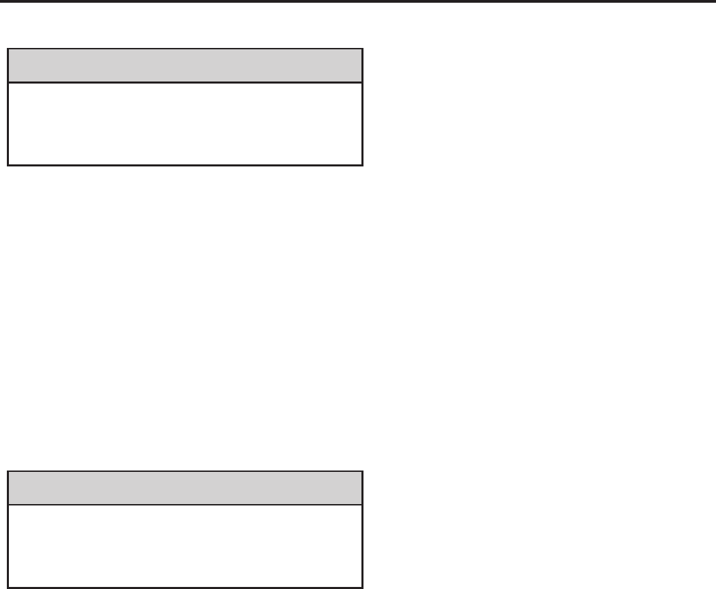
SLEEVE / DRAIN
Inspect the sleeve and drain system periodically (at least yearly or bi-yearly) and clean of all obstructions and
debris. Clean both areas with an antibacterial and antifungal cleaner. Rinse both items thoroughly with water and
ensure that the drain outlets are operating correctly. Check the sealant around the sleeve and reseal areas as
needed.
FRONT COVER
Clean the front cover when needed. Use a mild detergent. Wash and rinse with warm water. Allow it to dry
thoroughly before reinstalling it in the chassis.
CONDENSATE DISPOSAL SYSTEM
Part 1: The system’s rst stage increases energy efciency utilizing a factory installed fan that slings the cold
condensate onto the hot outdoor coil.
Part 2: When high outdoor humidity prevents slinger from disposing of all the condensate, the excess condensate
overows into the condensate drain pan and out of the ¾” internal drain connections.
Do not drill holes in the bottom of the drain pan or the
underside of the unit. Not following this notice could
result in damage to the unit or condensate water leaking
inappropriately which could cause water damage to
surrounding property.
NOTICE
If Parts 1 and 2 fail for any reason, excess condensate
overows from a spillway directly into the wall plenum to
the outside of the building. IF THIS OCCURS, THIS IS
A WARNING THAT THE CHASSIS OR DRAIN NEED
SERVICING.
NOTICE
39
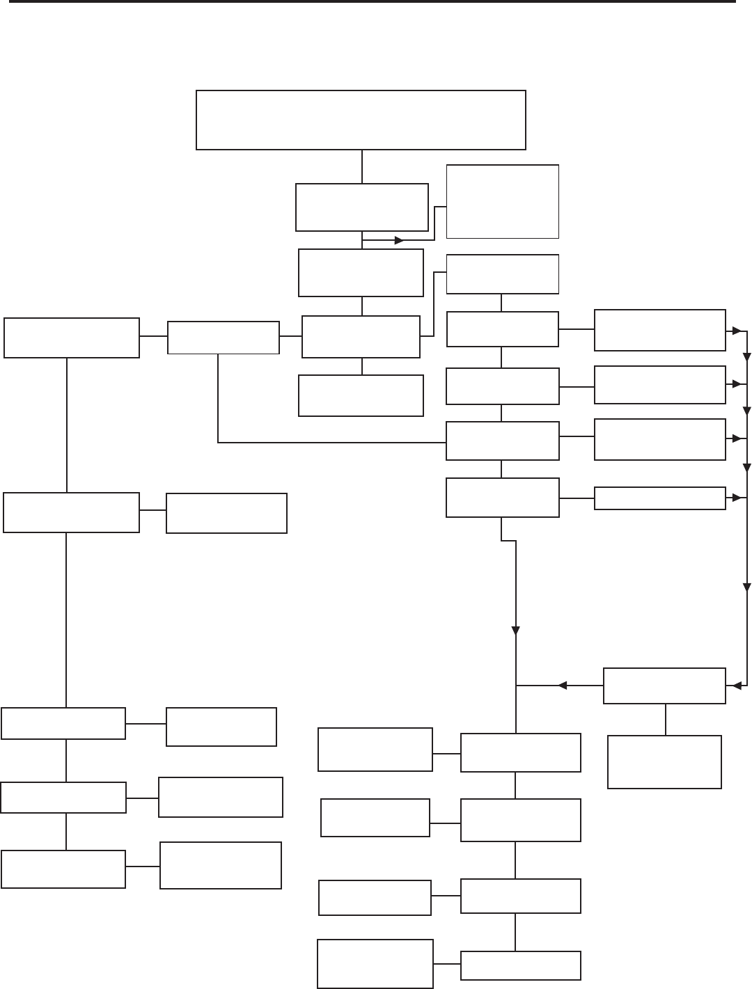
NO COOLING OPERATION
Insure that Fuses
are good and/or that
Circuit Breakers are
on and voltage is 208/230
Compressor and Fan
Motor should now
operate
See Refrigerant Circuit
diagnosis if unit still is
not cooling properly
Fan runs but
Compressor doesn't
Compressor runs but
Blower/Fan doesn't
Set thermostat to
"Cool," and the Temp.
below the present
Room Temp.
Nothing operates,
entire system
appears dead
Line voltage present
at the Transformer
Primary
24 Volts present at
208/230 Volts present
at #1 relay on board?
Y terminals on
t-stat and board?
Problems indicated with
Room Thermostat or
Control Wiring
Replace board
Problems indicated
in Blower Relay
of board
Yes
Yes
Yes Yes
Yes
Yes
Yes
Yes
Yes
No
No
No
No
No
No
O.K.
O.K.
No
Is Line Voltage present
at Motor Leads?
Check Capacitor, is
Capacitor Good? Replace Capacitor
Motor should run
Possible motor
problem indicated.
Check motor
thoroughly
Yes
Yes
No
No
No
Supply Circuit
problems, loose
Connections, or bad
Relays/Board
Replace Capacitor
and/or Start Assist
Device
Allow ample time
for pressures to
equalize
Possible Compressor
problem indicated.
See Compressor
Checks
Is Locked Rotor
Voltage a minimum of
197 Volts?
Are Capacitor and (if
so equipped) Start
Assist good?
Have System
Pressures Equalized?
Compressor should
run
Yes
Yes
No
No
No
No
Yes
Compressor and fan
motor should now
operate
See Refrigerant
Circuit Diagnosis if
unit still is not cooling
properly
Yes
Yes
No
Check Supply Circuit’s
jumper at transformer. If
okay, replace board
24 Volts at
“R” Terminal on board
Before continuing
check for Error
Codes, see
electronics control
diagnostics and
test mode, page 15
24V at t-stat and
control wiring?
Defective t-stat
defective control wiring
or transformer
Problems indicated with
Control Transformer
replace board
40
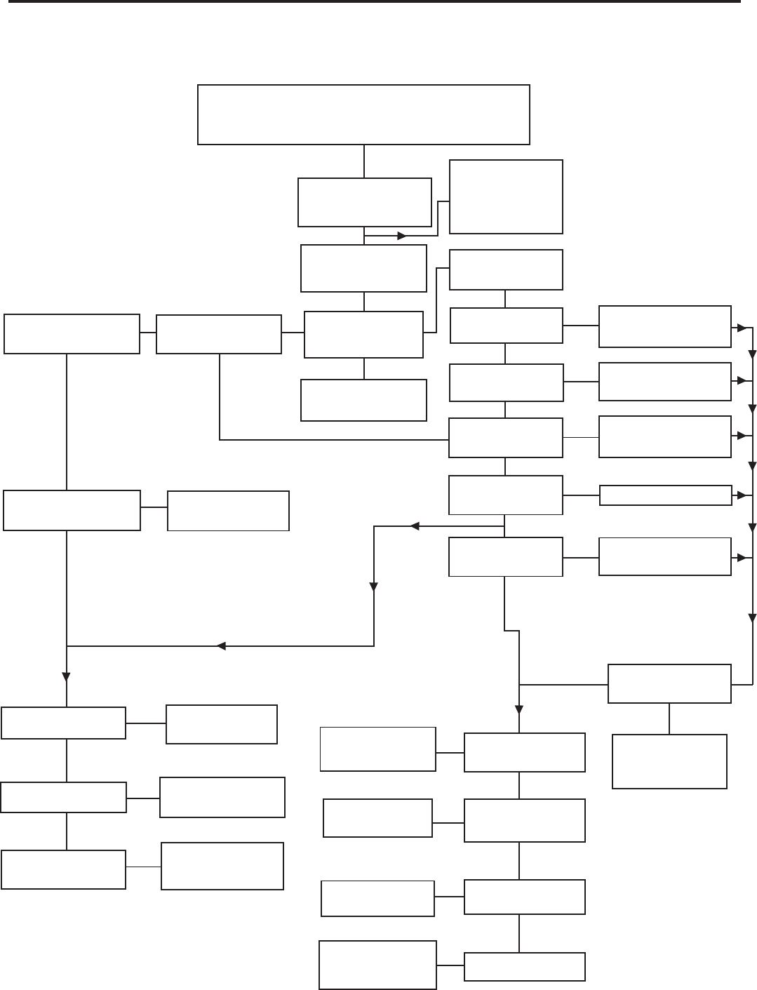
Yes
No
24V at t-stat and
control wiring?
Yes
No
24V at t-stat and
control wiring?
NO COOLING OPERATION
Before continuing
check for Error
Codes, see
electronics control
diagnostics and
test mode, page 15
Yes
Yes
Compressor outdoor
fan motor and indoor
blower should now
operate
See Refrigerant Circuit
diagnosis if unit still is
not cooling properly
Indoor blower runs but
outdoor fan motor and
compressor do not run
Compressor and outdoor
fan motor run but indoor
blower does not run
Set thermostat to
"Cool," move the Temp.
lever below the present
Room Temp.
Nothing operates,
entire system
appears dead
Line voltage present
at the Transformer
Primary
Problems indicated with
Room Thermostat or
Control Wiring
Yes Yes Yes
Yes
Yes
Yes
Yes
Yes
Yes
No
No
No
No
No
No
No
O.K.
No
Is Line Voltage present
at Motor Leads?
Check Capacitor, is
Capacitor Good? Replace Capacitor
Motor should run
Possible motor
problem indicated.
Check motor
thoroughly
Yes
Yes
Yes
No
No
No
Supply Circuit
problems, loose
Connections, or bad
Relays/Board
Replace Capacitor
and/or Start Assist
Device
Allow ample time
for pressures to
equalize
Possible Compressor
problem indicated.
See Compressor
Checks
Is Locked Rotor
Voltage a minimum of
197 Volts?
Are Capacitor and (if
so equipped) Start
Assist good?
Have System
Pressures Equalized?
Compressor should
run
Yes
Yes
No
No
No
No
Yes
Compressor and
outdoor fan motor
should now operate
See Refrigerant
Circuit Diagnosis
if unit still is not
cooling properly
Yes
Insure that Fuses
are good and/or that
Circuit Breakers are
on and voltage is 208/230
O.K.
208/230 Volts present
at #1 relay and “OD”
terminal on board?
208/230 Volts present
at compressor’s
contactor?
Problems indicated
in Blower Relay
of board
Replace board
Check Supply Circuit’s
jumper at transformer. If
okay, replace board
24 Volts at
“R” Terminal on board
24 Volts present at
Y terminals on
t-stat and board?
Problems indicated with
Control Transformer
replace board
Defective t-stat
defective control wiring
or transformer
Check contactor
If defective replace
41
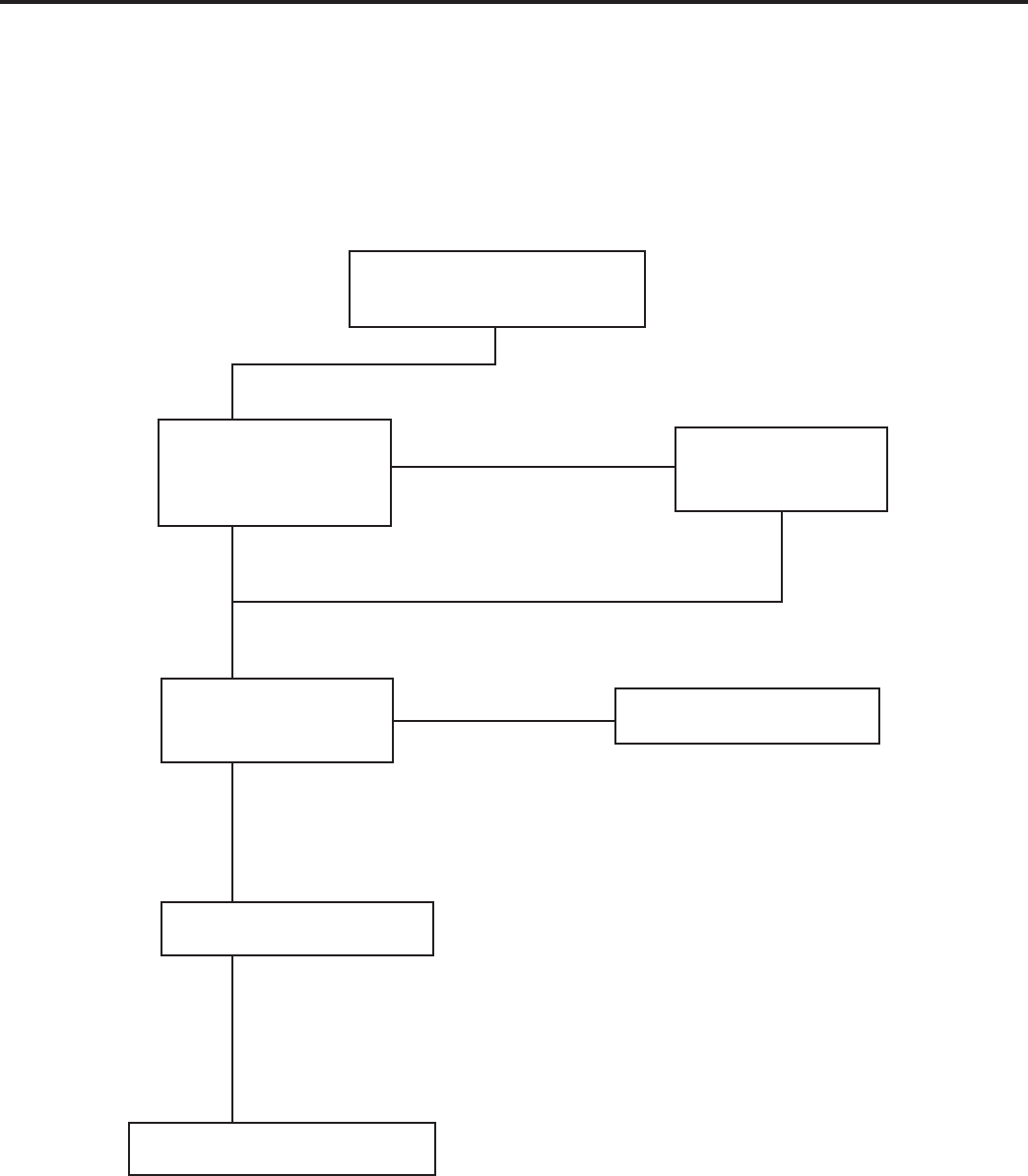
Replace Reversing Valve
NO
NO
YES
YES
Reversing Valve Stuck
YES
Replace Solenoid Coil
Is the Solenoid
Coil Good?
Is Line Voltage
Present at
Solenoid Valve?
Is Selector Switch
set for Heat?
SYSTEM COOLS WHEN
HEATING IS DESIRED.
HEAT PUMP MODE
42
REFRIGERANT SYSTEM DIAGNOSIS COOLING
REFRIGERANT SYSTEM DIAGNOSIS HEATING
Low Load Conditions High Load Conditions Low Load Conditions High Load Conditions
Low Air Flow Across High Air Flow Across Refrigerant System Low Air Flow Across
Indoor Coil Indoor Coil Restriction Outdoor Coil
Refrigerant System Reversing Valve not Reversing Valve not Overcharged
Restriction Fully Seated Fully Seated
Undercharged Overcharged Non-Condensables (air)
Undercharged System
Moisture in System Defective Compressor Defective Compressor
LOW SUCTION PRESSURE HIGH SUCTION PRESSURE LOW HEAD PRESSURE HIGH HEAD PRESSURE
LOW SUCTION PRESSURE HIGH SUCTION PRESSURE LOW HEAD PRESSURE HIGH HEAD PRESSURE
PROBLEM PROBLEM PROBLEM PROBLEM
PROBLEM PROBLEM PROBLEM PROBLEM
Low Air Flow Across Outdoor Ambient Too High Refrigerant System Outdoor Ambient Too High
Outdoor Coil for Operation in Heating Restriction For Operation In Heating
Refrigerant System Reversing Valve not Reversing Valve not Low Air Flow Across
Restriction Fully Seated Fully Seated Indoor Coil
Undercharged Overcharged
Defective Compressor
Undercharged Overcharged
Moisture in System Defective Compressor Non-Condensables (air)
in System
43
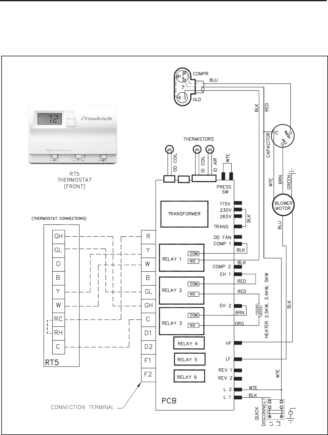
NOTE: THE DIAGRAM ABOVE, ILLUSTRATES THE TYPICAL THERMOSTAT WIRING FOR TWO SPEED
FAN OPERATION. SEE THE UNIT CONTROL PANEL FOR THE ACTUAL UNIT WIRING DIAGRAM
AND SCHEMATIC.
44
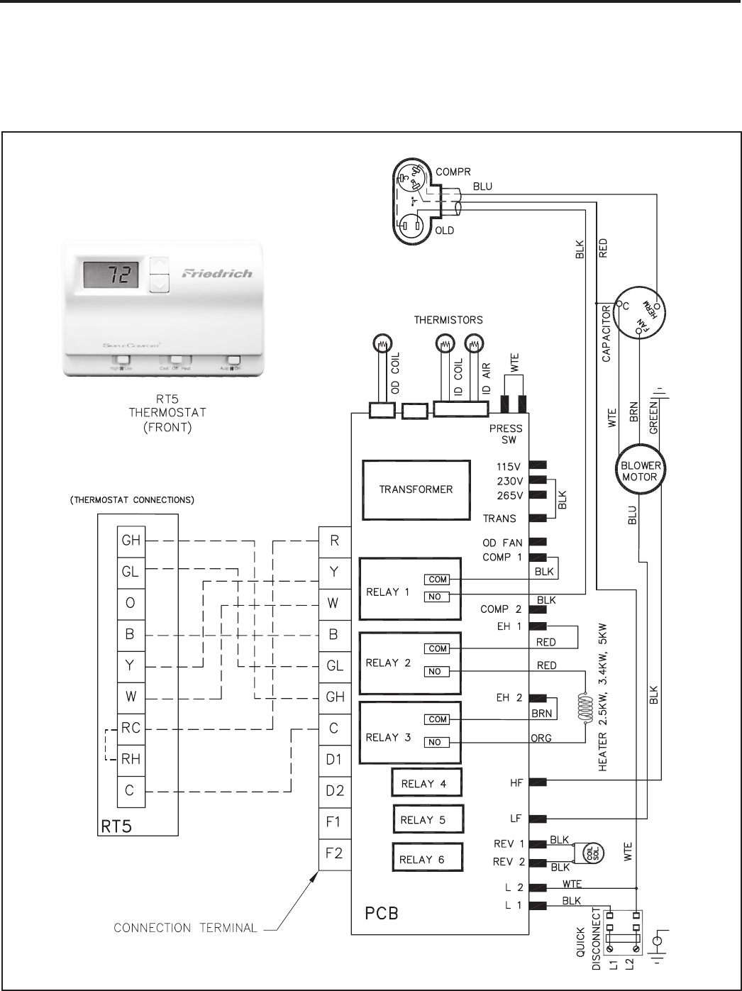
NOTE: THE DIAGRAM ABOVE, ILLUSTRATES THE TYPICAL THERMOSTAT WIRING FOR TWO SPEED
FAN OPERATION. SEE THE UNIT CONTROL PANEL FOR THE ACTUAL UNIT WIRING DIAGRAM
AND SCHEMATIC.
45
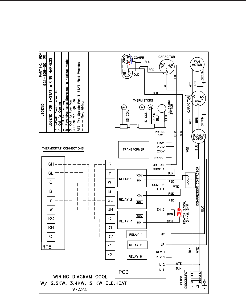
46
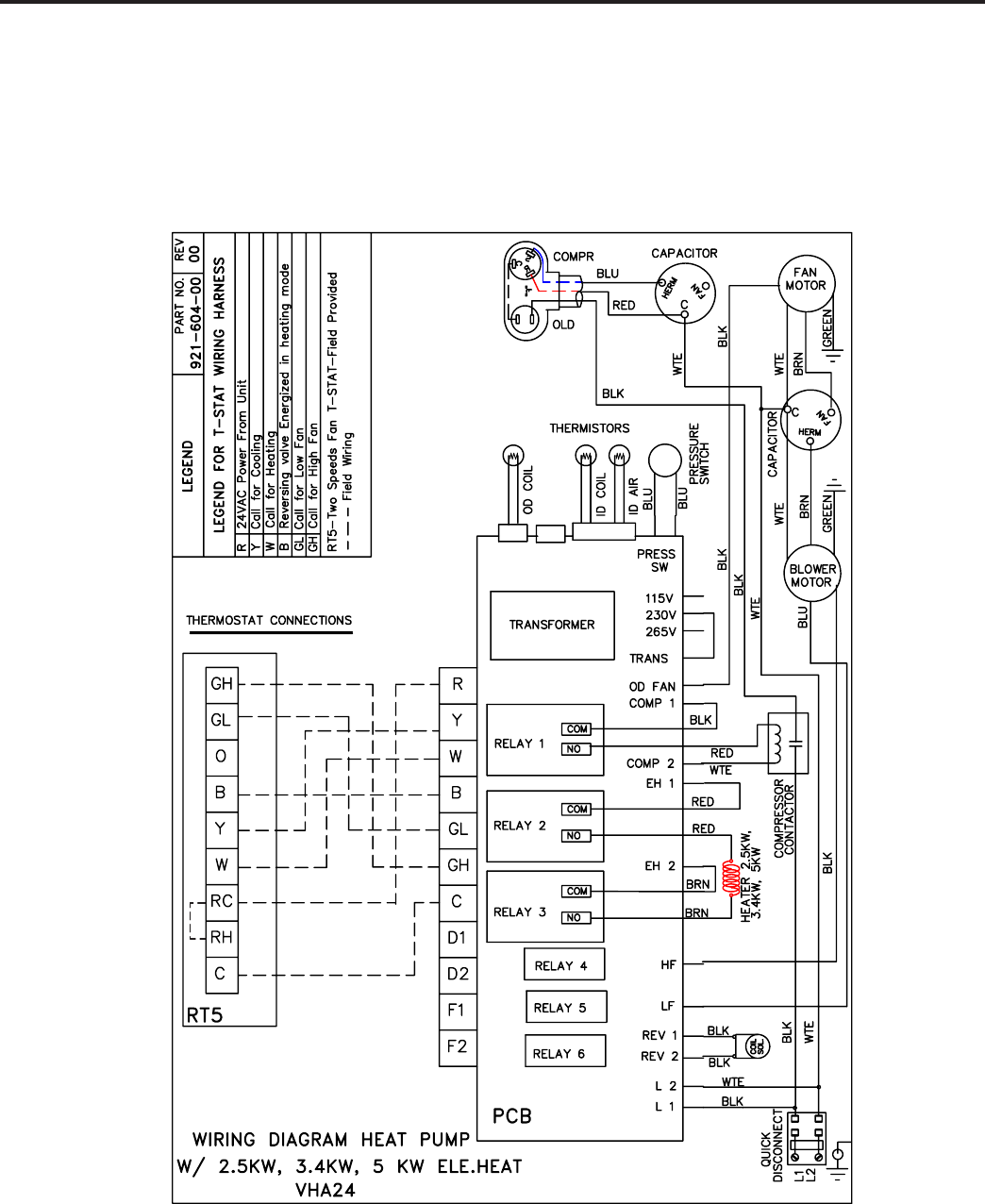
47
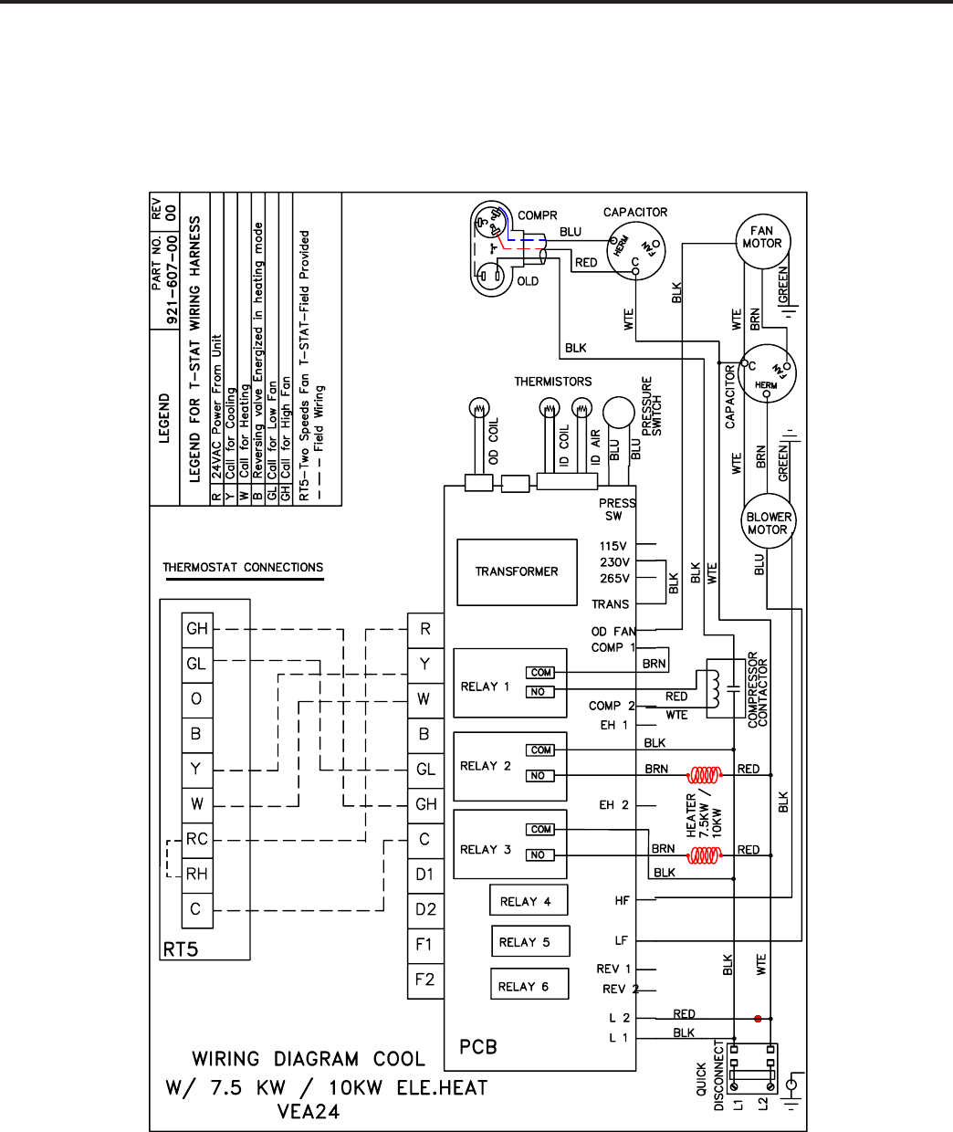
48
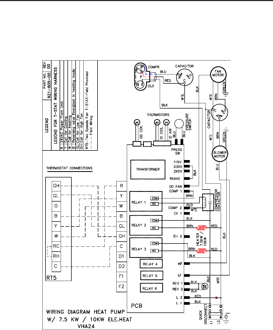
49
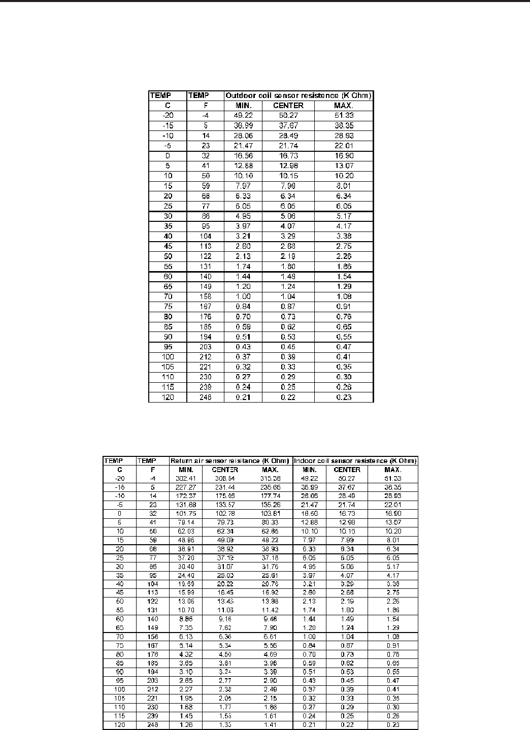
50
Outdoor Coil
Return Air Indoor Coil
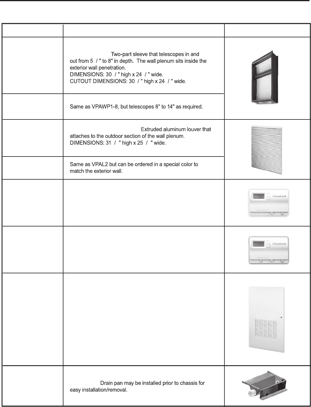
ACCESSORIES
DIGITAL REMOTE WALL THERMOSTAT
Single stage
thermostat. Features high/low fan speed switch. Thermostat
is hard wired and can be battery powered or unit powered.
Features backlit display and multiple configured modes.
DIGITAL REMOTE WALL THERMOSTAT
Single stage
thermostat, used on VERT-I-PAK units. Hard wired with single
speed fan. Direct replacement for RT2.
ARCHITECTURAL LOUVER
116 916
WALL PLENUM
12
3818
7858
DRAIN PAN
OTOHP NOITPIRCSED LEDOM
VPAWP1-8
VPDP1
VPRG4
RT4
RT5
VPSC2
VPAL2
VPAWP1-14
ACCESS PANEL / RETURN AIR GRILLE – Serves as an access
panel to chassis and interior return air grille. A field-supplied
(25" x 20") filter is mounted inside the hinged access door.
Kit contains hinge bracket for mounting the door with the return
air openings high or low on the door for optimal sound attenuation.
For 9,000 / 12,000 / 18,000 Btu models, it is recommended to
install the door with the hinge on the right side and the return air
openings high on the door. For 24,000 Btu models, it is
recommended to install the hinge on the left side with the return
air openings low on the door.
DIMENSIONS: 58" high x 29" wide.
COUTOUT DIMENSIONS: 55 3/4" high x 27" wide.
24,000 BTU ONLY
51

Friedrich Air Conditioning Company
P.O. Box 1540
San Antonio, TX 78295
210.357.4400
www.friedrich.com
VERT-I-PAK® A SERIES
SINGLE PACKAGE VERTICAL AIR CONDITIONERS
LIMITED WARRANTY
SAVE THIS CERTIFICATE. It gives you specific rights. You may also have other rights which may vary from state to state and province to
province.
In the event that your unit needs servicing, contact your nearest authorized service center. If you do not know the nearest service center,
ask the company that installed your unit or contact us - see address and telephone number above. To obtain service and/or warranty parts
replacement, you must notify an authorized FRIEDRICH Air Conditioning Co. service center, distributor, dealer, or contractor of any defect
within the applicable warranty period.
When requesting service: please have the model and serial number from your unit readily available.
Unless specified otherwise herein, the following applies:
FRIEDRICH VERT-I-PAK A SERIES VERTICAL AIR CONDITIONERS AND HEAT PUMPS
LIMITED WARRANTY - FIRST YEAR (Twelve (12) months from the date of installation). Any part found to be defective in the material
or workmanship will be repaired or replaced free of charge by our authorized service center during the normal working hours; and
LIMITED WARRANTY - SECOND THROUGH FIFTH YEAR (Sixty (60) months from the date of installation). ON THE SEALED
REFRIGERATION SYSTEM. Any part of the sealed refrigeration system that is defective in material or workmanship will be repaired or
replaced free of charge (excluding freight charges) by our authorized service center during normal working hours. The sealed refrigeration
system consists of the compressor, metering device, evaporator, condenser, reversing valve, check valve, and the interconnecting tubing.
These warranties apply only while the unit remains at the original site and only to units installed inside the continental United
States, Alaska, Hawaii, Puerto Rico and Canada. The warranty applies only if the unit is installed and operated in accordance with
the printed instructions and in compliance with applicable local installation and building codes and good trade practices. For
international warranty information, contact the Friedrich Air Conditioning Company - International Division.
Any defective part to be replaced must be made available to FRIEDRICH in exchange for the replacement part. Reasonable proof must be
presented to establish the date of install, otherwise the beginning date of this certificate will be considered to be our shipment date plus sixty
days. Replacement parts can be new or remanufactured. Replacement parts and labor are only warranted for any unused portion of the
unit’s warranty.
We will not be responsible for and the user will pay for:
1. Service calls to:
A) Instruct on unit operation. B) Replace house fuses or correct house wiring. C) Clean or replace air filters. D) Remove the unit
from its installed location when not accessible for service required. E) Correct improper installations.
2. Parts or labor provided by anyone other than an authorized service center.
3. Damage caused by:
A) Accident, abuse, negligence, misuse, riot, fire, flood, or acts of God. B) Operating the unit where there is a corrosive atmosphere
containing chlorine, fluorine, or any damaging chemicals (other than in a normal residential environment). C) Unauthorized
alteration or repair of the unit, which in turn affects its stability or performance. D) Failing to provide proper maintenance and
service. E) Using an incorrect power source. F) Faulty installation or application of the unit.
We shall not be liable for any incidental, consequential, or special damages or expenses in connection with any use or failure of
this unit. We have not made and do not make any representation or warranty of fitness for a particular use or purpose and there
is no implied condition of fitness for a particular use or purpose. We make no expressed warranties except as stated in this
certificate. No one is authorized to change this certificate or to create for us any other obligation or liability in connection with
this unit. Any implied warranties shall last for one year after the original purchase date. Some states and provinces do not allow
limitations on how long an implied warranty or condition lasts, so the above limitations or exclusions may not apply to you. The provisions of
this warranty are in addition to and not a modification of or subtraction from the statutory warranties and other rights and remedies provided
by law.
Performance of Friedrich’s Warranty obligation is limited to one of the following methods:
1. Repair of the unit
2. A refund to the customer for the prorated value of the unit based upon the remaining warranty period of the unit.
3. Providing a replacement unit of equal value
The method of fulfillment of the warranty obligation is at the sole discretion of Friedrich Air Conditioning.
In case of any questions regarding the provisions of this warranty, the English version will govern.
(10-08)
52

FRIEDRICH AIR CONDITIONING CO.
Post Ofce Box 1540 · San Antonio, Texas 78295-1540
4200 N. Pan Am Expressway · San Antonio, Texas 78218-5212
(210) 357-4400 · FAX (210) 357-4490
www.friedrich.com
Printed in the U.S.A.
TECHNICAL SUPPORT
CONTACT INFORMATION

FRIEDRICH AIR CONDITIONING CO.
Post Ofce Box 1540 · San Antonio, Texas 78295-1540
4200 N. Pan Am Expressway · San Antonio, Texas 78218-5212
(210) 357-4400 · FAX (210) 357-4490
www.friedrich.com
Printed in the U.S.A. VPK-ServMan (04-09)
