Friedrich Air Conditioner Cp10A10 Users Manual ~A20306A(G/Ç¥Áö)
ZQ10B10 to the manual f23bcabc-be3c-49d8-91d9-557606460854
2015-02-02
: Friedrich Friedrich-Friedrich-Air-Conditioner-Cp10A10-Users-Manual-428234 friedrich-friedrich-air-conditioner-cp10a10-users-manual-428234 friedrich pdf
Open the PDF directly: View PDF ![]() .
.
Page Count: 28
Room Air Conditioner
Service and Parts
Manual
ZQ08/10;CP08/10/12 (06/05)
ZQ08B10 ZQ10B10 CP08A10 CP10A10 CP12A10

—2—
1. PREFACE
1.1 SAFETY PRECAUTIONS................................2
1.2 INSULATION RESISTANCE TEST .................2
1.3 SPECIFICATIONS...........................................3
1.4 FEATURES......................................................4
1.5 CONTROL LOCATIONS .................................4
2.
DISASSEMBLY INSTRUCTIONS
2.1 MECHANICAL PARTS ....................................6
2.1.1 FRONT GRILLE .....................................6
2.1.2 CABINET ................................................6
2.1.3 CONTROL BOX .....................................6
2.2 AIR HANDLING PARTS ..................................7
2.2.1 AIR GUIDE AND TURBO FAN...............7
2.2.2 FAN ........................................................7
2.2.3 SHROUD ................................................8
2.3 ELECTRICAL PARTS......................................8
2.3.1 OVERLOAD PROTECTOR ....................8
2.3.2 COMPRESSOR......................................8
2.3.3 CAPACITOR...........................................9
2.3.4 POWER CORD ......................................9
2.3.5 MOTOR ................................................10
2.4 REFRIGERATION CYCLE ............................10
2.4.1 CONDENSER.......................................10
2.4.2 EVAPORATOR.....................................10
2.4.3 CAPILLARY TUBE ...............................11
3. TROUBLESHOOTING GUIDE
3.1 OUTSIDE DIMENSIONS...............................13
3.2 PIPING SYSTEM...........................................14
3.3 TROUBLESHOOTING GUIDE .....................15
1. PREFACE
This SERVICE MANUAL provides various service information, including the mechanical and electrical
parts etc. This room air conditioner was manufactured and assembled under a strict quality control system.
The refrigerant is charged at the factory. Be sure to read the safety precautions prior to servicing the unit.
CONTENTS
.
.
1.1 SAFETY PRECAUTIONS
1. When servicing, turn the unit Off and unplug the
power cord.
2. Observe the original lead dress.
If a short circuit is found, replace all parts which have
been overheated or damaged by the short circuit.
3. After servicing, make an insulation resistance test to
prevent the customer from being exposed to shock
hazards.
1.2
INSULATION RESISTANCE TEST
1. Unplug the power cord and connect a jumper between 2 pins
(black and white).
2. The grounding conductor (green or green and yellow) is to be
open.
3. Measure the resistance value with an ohm meter between the
jumpered lead and each exposed metallic part on the equip-
ment at each working status.
4. The value should be over 1 MΩ.
5. EXPLODED VIEW ..................................20
6. REPLACEMENT PARTS LIST........21
4. SCHEMATIC DIAGRAM.....................19
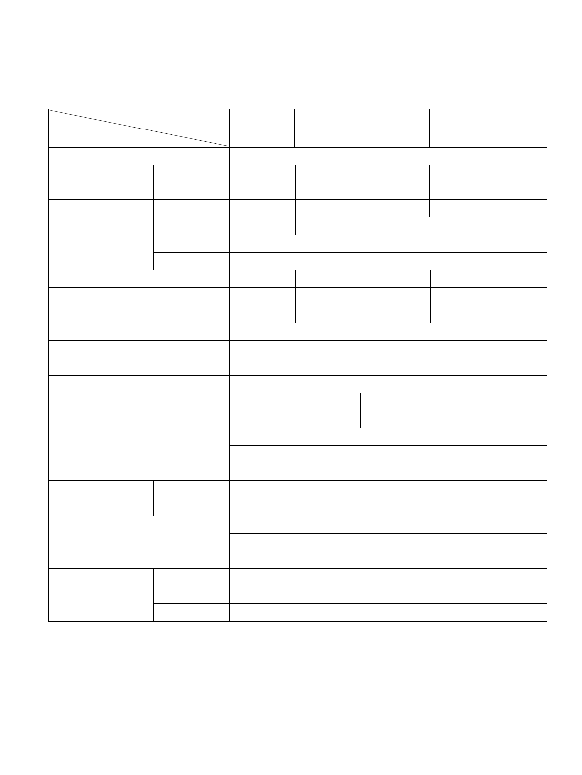
7,800 10,000 7,800 12,000
800 1,020 730 1,110
7.6 9.2 6.6 10.2
9.7 10.8
26.7(DB)* 19.4(WB)**
35(DB )* 23.9(WB )**
300g(10.6oz)
520g(18.3oz)
525g(18.5oz)
510g(18.0oz)
2 R OW 11S TAC KS
3 R OW 11S TAC KS
2 R OW 10S TAC KS
3 R OW 12S TAC KS
2 R OW 16S TAC KS
2 R OW 17S TAC KS
2 R OW 17S TAC KS (L)
TUR BO FAN
P R OPE LLE R TYP E F AN WITH S LING E R R ING
2/3 3/3
6 POLE S
R OTAR Y S WIT C H
R E MOTE C ONTR OLLE R
THE R MOS TAT THE R MIS TOR
VE R TIC AL LOUVE R (R IG HT & LE FT)
HOR IZONTAL LOUVE R (UP & DOWN)
S LIDE IN-OUT C HAS S IS
OVE R LOAD P R OTE C TOR
INT E R NAL THE R MAL P R OTE C TOR
(3 WIR E WITH G R OUDING )
ATTAC HME NT P LUG (C OR D-C ONNE C TE D TYP E )
DR AIN PIP E OR S PLAS HE D BY FAN S LING E R
62/28
20
3
/
32
x 13
29
/
32
x 19
3
/
8
510 x 354 x 490
P OWE R S UPP LY
C OOLING C AP AC IT Y (B tu/h)
INP UT (W )
R UNNING C UR R E NT (A)
E .E .R (B TU/W.h)
OPE R ATING INDOOR (¡ C )
C ONDITION OUTDOOR (¡ C )
R E FR IG E R ANT (R -22) C HAR GE
E V AP OR AT OR
C ONDE NS E R
FAN, INDOOR
FAN, OUTDOOR
FAN S PE E DS , FAN/C OOLING
FAN MOTOR
OPE R ATION CONT R OL
R OOM TE MP . C ONT R OL
AIR DIR E C T ION C ONT R OL
C ONS T R UC TION
P R OTE CT OR C OMP R E S S OR
FAN MOTOR
P OWE R C OR D
DR AIN S Y S T E M
NE T WE IG HT (lbs/kg)
OUTS IDE DIME NS ION (inch)
(W xH xD) (mm)
ZQ08B 10 ZQ10B 10 C P 08A 10 C P 10A 10
C P 12A 10
MODE L S
ITE MS
1.3.1 FOR ZQ08B 10,ZQ10B 10,C P 08A10,C P 10A10,C P 12A10
* DB:Dry B ulb
**
WB:Wet B ulb
10,000
930
8.5
9.8
2 R OW 16S TAC KS (L)
420g(14.8oz)
—3—
1.3 SPECIFICATIONS
1ø, 115V, 60HZ
—4—
1.4 FEATURES
• Designed for COOLING ONLY.
• Powerful and whispering cooling.
• Slide-in and slide-out chassis for the simple
installation and service.
• Low air-intake, top cooled-air discharge.
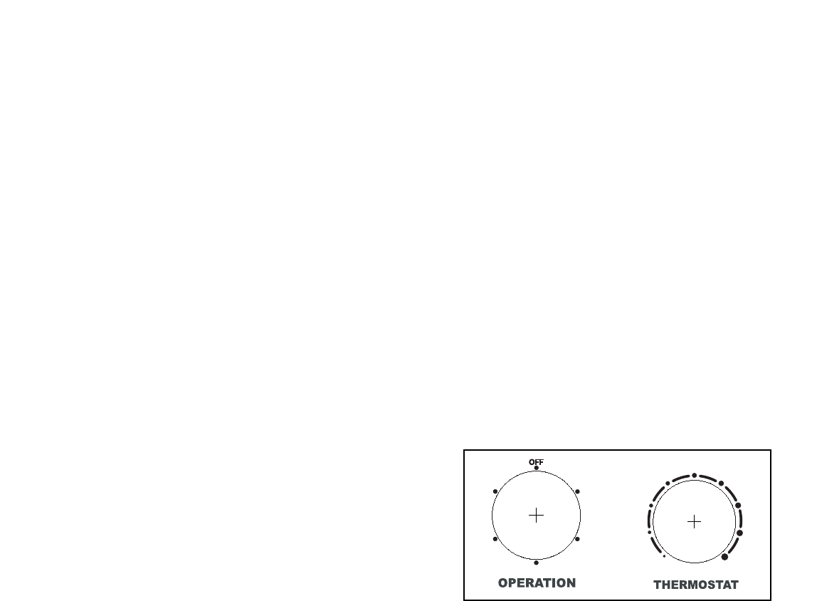
1.5 CONTROL LOCATIONS
• THERMOSTAT (Fig A)
Thermostat will automatically control the temperature of
the discharge air. For a cooler setting, turn clockwise,
For a warmer setting, turn counter clockwise.
• OPERATION (Fig A)
OFF : Turns the air conditioner off.
MED FAN : Medium fan speed without cooling.
LOW FAN : Low fan speed without cooling.
HIGH COOL : Cooling with the high fan speed.
MED COOL : Cooling with the medium fan speed.
LOW COOL : Cooling with the low fan speed.
• Built-in adjustable Thermistor
• Washable one-touch filter
• Compact size
• Reliable and efficient rotary compressor is equipped.
HIGH
COOL
HIGH
COOL
MED
FAN
MED
FAN
LOW
FAN
LOW
FAN
LOW COOLLOW COOL
MED
COOL
MED
COOL 1199
88
22
77
33
66
4455
Fig A
—5—
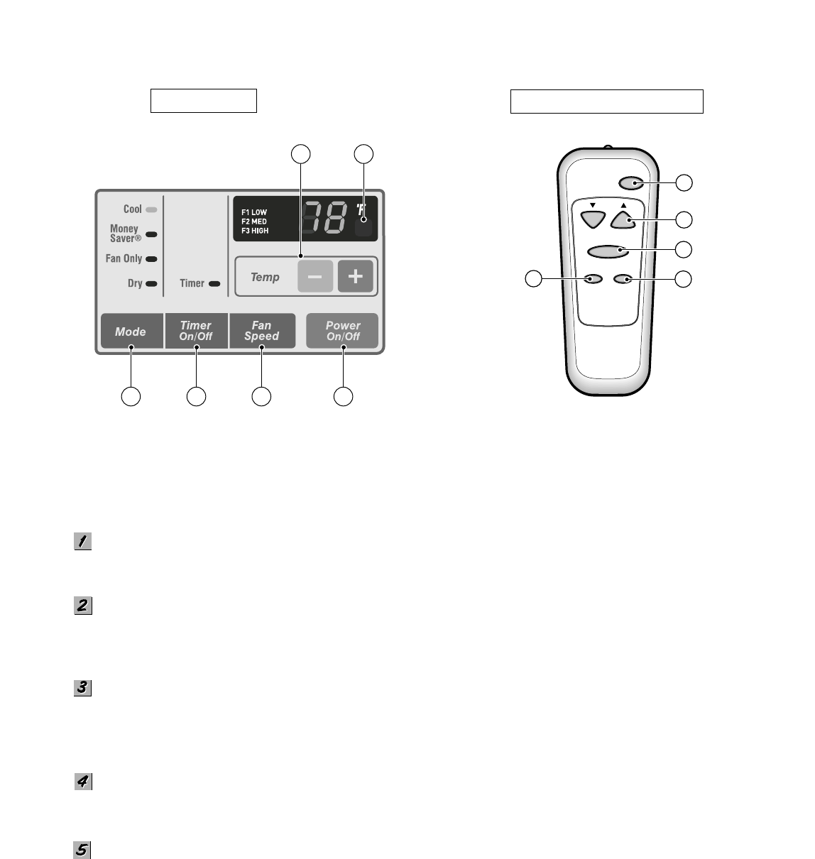
Precaution: The Remote Control unit will not function properly if strong light strikes the sensor window of the air
conditioner or if there are obstacles between the Remote Control unit and the air conditioner.
POWER BUTTON
To turn the air conditioner ON. To turn the air conditioner OFF, push the button again.
This button takes priority over any other buttons.
TEMPERATURE SETTING BUTTON
This button can automatically control temperature of the room. The temperature can be set within a range of 60'F to 86'F
by 1'F.
OPERATION MODE SELECTION BUTTON
Every time you push this button, it will shift operation between COOL, ENERGY SAVER, FAN and DRY modes.
- Mone
y Saver: If Money Save mode is selected, the fan stops when the compressor stops cooling.
Approximately every 3 minutes the fan will turn on and check the room air to determine if cooling is needed.
FAN SPEED SELECTOR
Every time you push this button, it will shift fan speeds, as follows.
(Hi ➔ Low ➔ Med ➔ Hi ➔ Low ➔...)
ON/OFF TIMER BUTTON
ON - When the air conditioner is off,it can be set to automatically come on in 1 to12 hours from its previous setting.
P owe r
Temp
Fan S peed
Timer Mode
1
2
3
4
5
R E MOTE CONTR OL
DIS P L AY
Fig B Fig C
1
2
453
6
Refer to Fig B&Fig C
Each touch will increase the timer by 1 hour.
OFF - When the air conditioner is on, it can be set to automatically turn off in 1 to 12 hours. Each touch will increase
the timer by 1 hour. After the timer has been on for 30min, the temperature will automatically rise 2F, and after another
another 30min, it will rise 2F again. The temperature will stay the same until the timer goes off.
To cancel the timer, press the timer pad until the display time disappears.
—6—
2.1 MECHANICAL PARTS
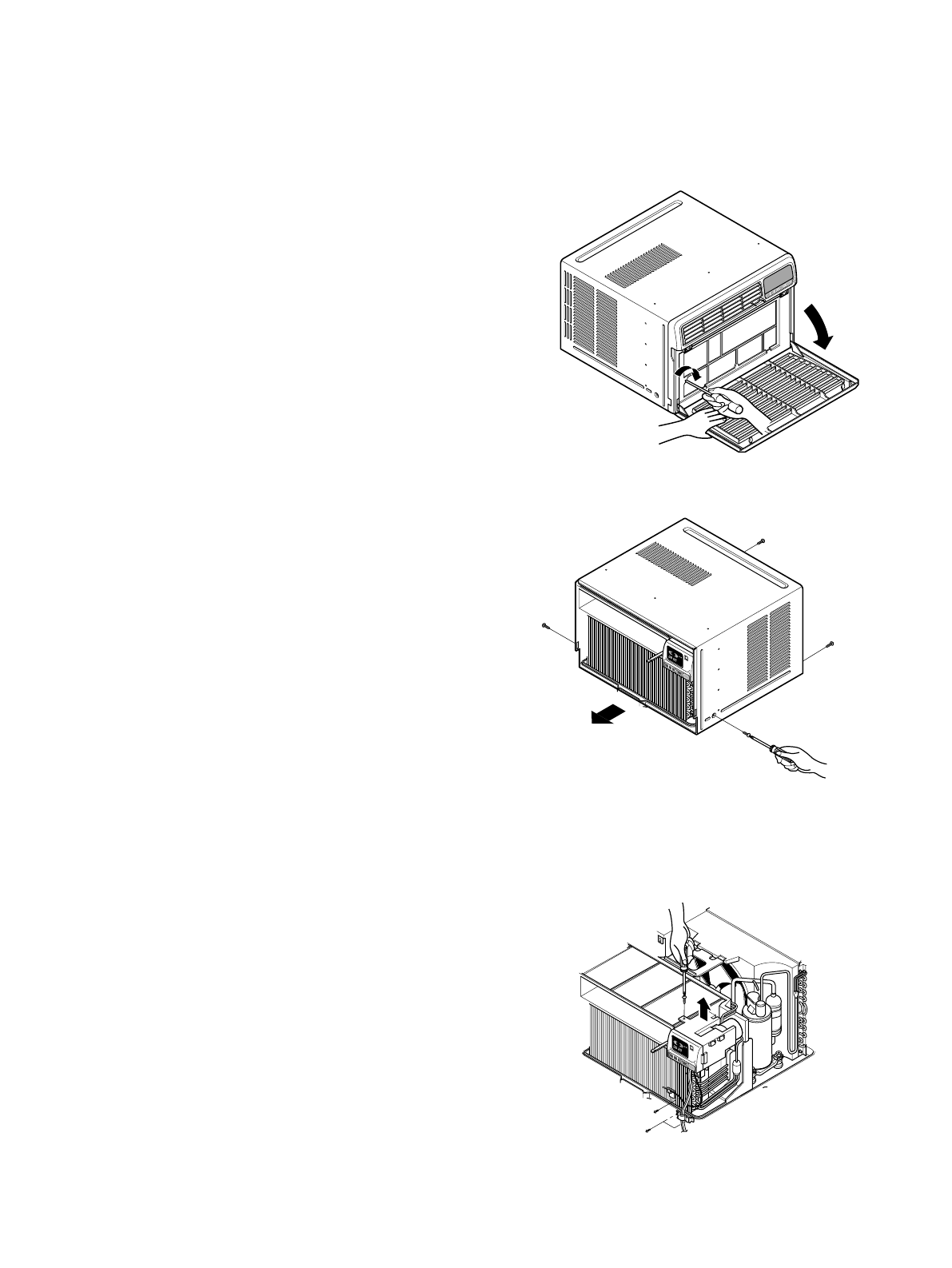
2.1.1 FRONT GRILLE
1. Open the lnlet grille downward and remove the air
filter.
2. Remove the screw which fastens the front
grille.(See Figure 1)
3. Pull the front grille from the right side.
4. Remove the front grille.(There are 4 hooks.)
5. Re-install the components by referring to the
removal procedure, above.
2.1.2 CABINET
1. After disassembling the FRONT GRILLE, remove
the 2 screws which fasten the cabinet at both
sides.
2. Remove the 2 screws which fasten the cabinet at
back.
3. Pull the base pan forward. (See Figure 2)
4. Remove the cabinet.
5. Re-install the components by referring to the
removal procedure, above.
2.1.3 CONTROL BOX
1. Remove the front grille. (Refer to section 2.1.1)
2. Remove the cabinet. (Refer to section 2.1.2)
3. Remove the 2 screws which fasten the power
cord.
4. Disconnect the grounding screw from the
evaporator channel.
5. Remove the 1 screw which fastens the control box
cover.
6. Remove the housing which connects PCB(CP 08/10/12)
or connector(ZQ 08/10) and motor wire in the control box.
7. Remove the nut which fastens the terminal cover.
8. Remove the terminal cover.
9. Remove all the leads from the overload protector.
10. Discharge the capacitor by placing a 20,000
ohm resistor across the capacitor terminals.
11. Raise the control box upward completely.
(See Figure 3)
12. Re-install the components by referring to the
removal procedure, above.
(Refer to the circuit diagram found on page 27 in
this manual and on the control box.)
TIMEMODETEMPPOWER
FAN
SPEED
TIMEMODETEMPPOWER
FAN
SPEED
COOL
INDOORDESIRED
ENERGY
SAVER
AIR
PURYFIER
AUTO
RESTART
FAN
FAN
DRYHEAT
DEFROST
TIMEMODETEMPPOWER
FAN
SPEED
COOL
INDOORDESIRED
ENERGY
SAVER
AIR
PURYFIER
AUTO
RESTART
FAN
FAN
DRYH
EAT
DEFROST
2. DISASSEMBLY INSTRUCTIONS
— Before the following disassembly, set POWER SWITCH to OFF and disconnect the power cord.
Figure 1
Figure 3
Figure 2
—7—
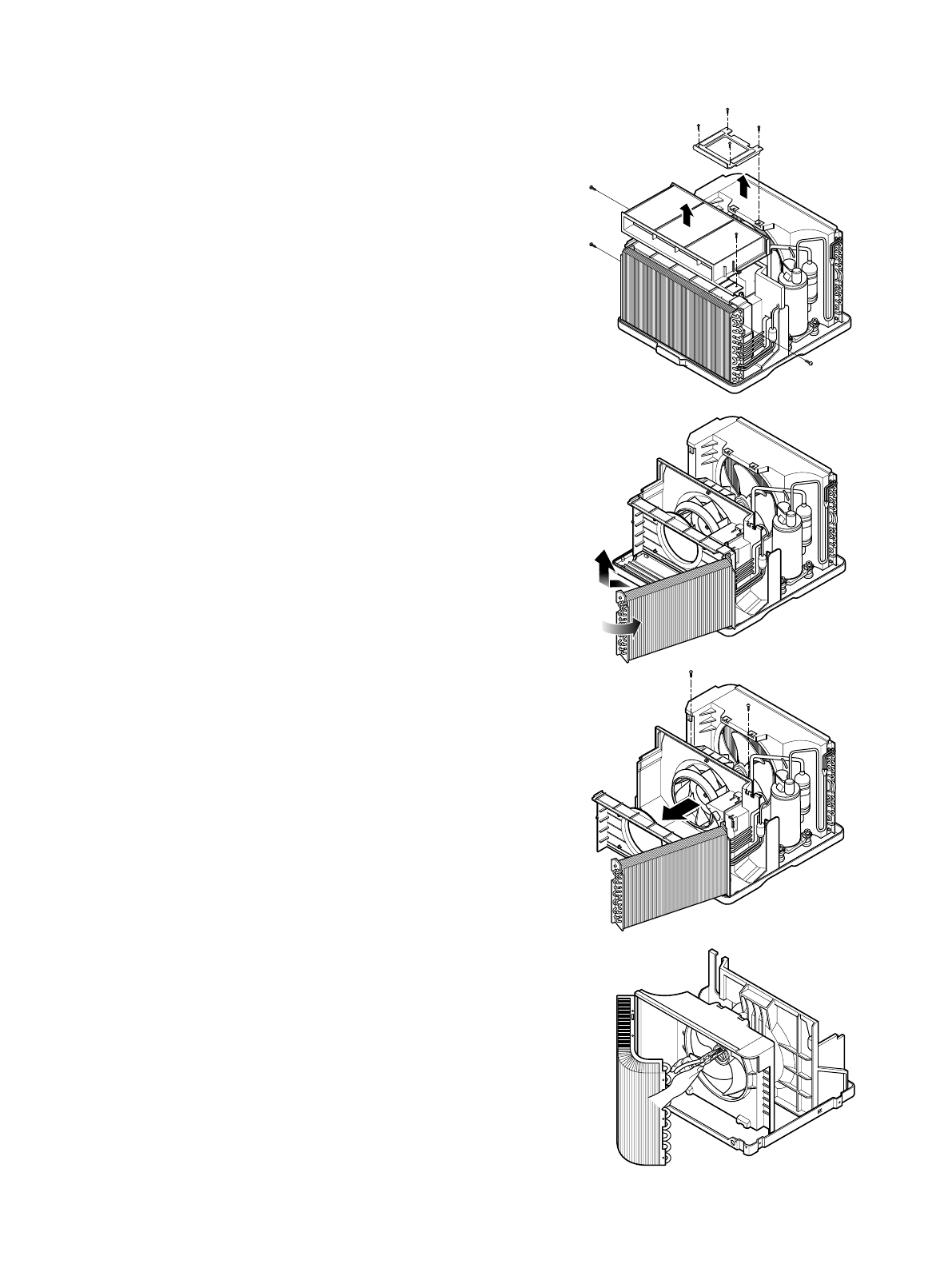
2.2 AIR HANDLING PARTS
2.2.1 AIR GUIDE AND TURBO FAN
1. Remove the front grille. (Refer to section 2.1.1)
2. Remove the cabinet. (Refer to section 2.1.2)
3. Remove the control box. (Refer to section 2.1.3)
4. Remove the 4 screws which fasten the brace.
5. Remove the brace.
6. Remove the 2 screws which fasten the air guide
upper.
7. Remove the air guide upper.(See figure 4)
8. Remove the 2 screws which fasten the evaporator.
9. Move the evaporator forward pulling it upward
slightly. (See Figure 5)
10. Pull the hook out of orifice by pushing the tabs
and remove it. (See Figure 6)
11. Using pliers remove the clamp
secures the turbo fan.
12. Remove the turbo fan.
13. Remove the 2 screws which fasten the air guide
to the base pan.
14. Move the air guide backward, and pull out from
the base pan.(Move the air guide lower carefully.)
15. Re-install the components by referring to the
removal procedure, above.
2.2.2 FAN
1. Remove the cabinet. (Refer to section 2.1.2)
2. Remove the brace (Refer to section 2.2.1)
3. Remove the 5 screws which fasten the condenser.
4. Move the condenser to the left carefully.
5. Remove the clamp which secures the fan.
6. Remove the fan. (See Figure 7)
7. Re-install by referring to the removal procedure.
Figure 4
Figure 5
Figure 6
Figure 7
—8—
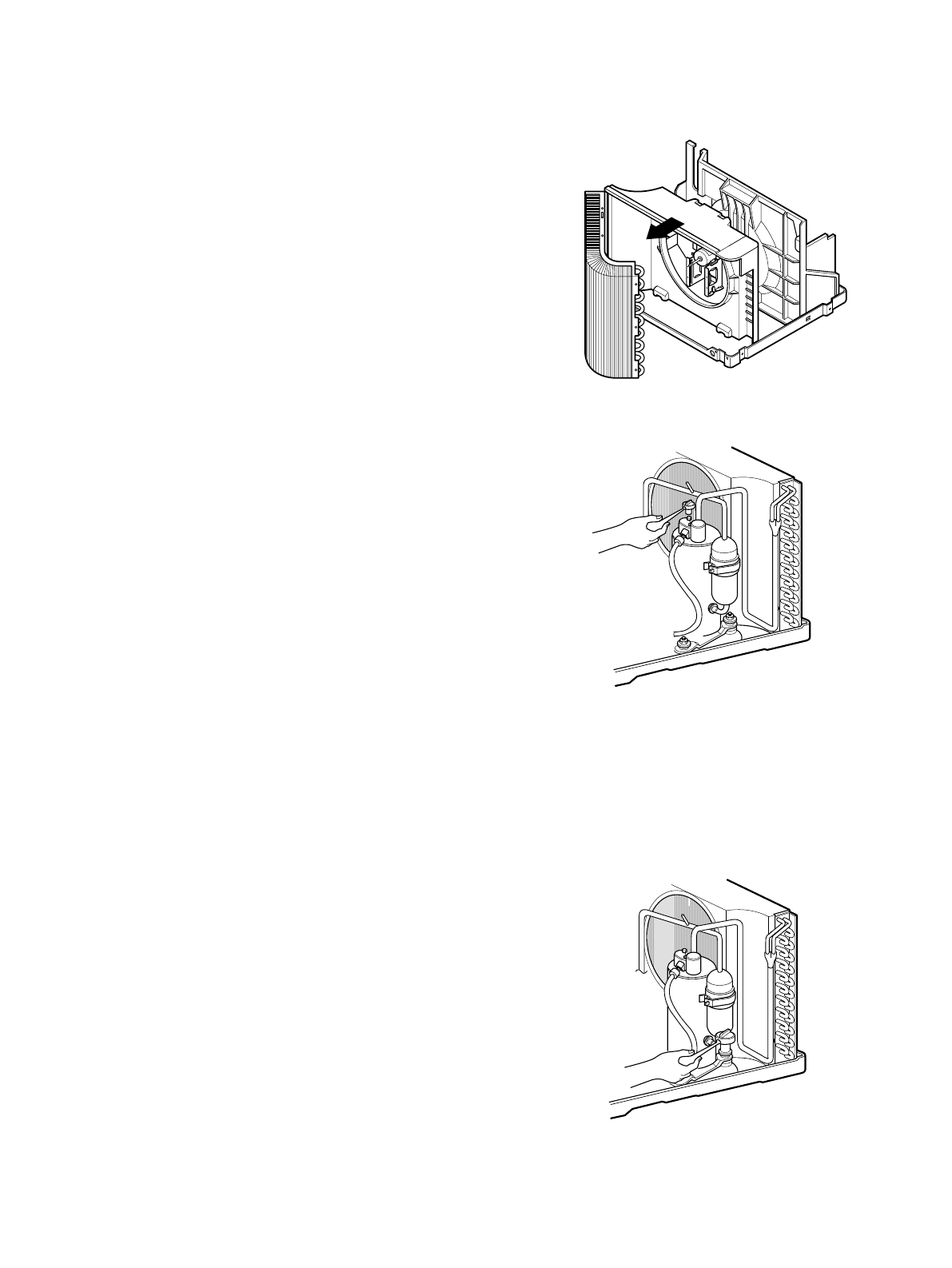
2.2.3 SHROUD
1. Remove the fan. (Refer to section 2.2.2)
2. Remove the shroud. (See Figure 8)
3. Re-install the components by referring to the
removal procedure, above.
2.3 ELECTRICAL PARTS
2.3.1 OVERLOAD PROTECTOR
1. Remove the cabinet. (Refer to section 2.1.2)
2. Remove the nut which fastens the terminal cover.
3. Remove the terminal cover. (See Figure 9)
4. Remove all the leads from the overload protector.
5. Remove the overload protector.
6. Re-install the components by referring to the
removal procedure, above.
2.3.2 COMPRESSOR
1. Remove the cabinet. (Refer to section 2.1.2)
2. Discharge the refrigerant system using a FreonTM
Recovery System.
If there is no valve to attach the recovery system to,
install one (such as a WATCO A-1) before venting
the FreonTM. Remove the valve when finished
3. Remove the overload protector. (Refer to section
2.3.1)
4. After purging the unit completely, unbraze the
suction and discharge tubes at the compressor
connections.
5. Remove the 3 nuts and the 3 washers which
fasten the compressor.
6. Remove the compressor. (See Figure 10)
7. Re-install the components by referring to the
removal procedure, above.
Figure 8
Figure 9
Figure 10
—9—
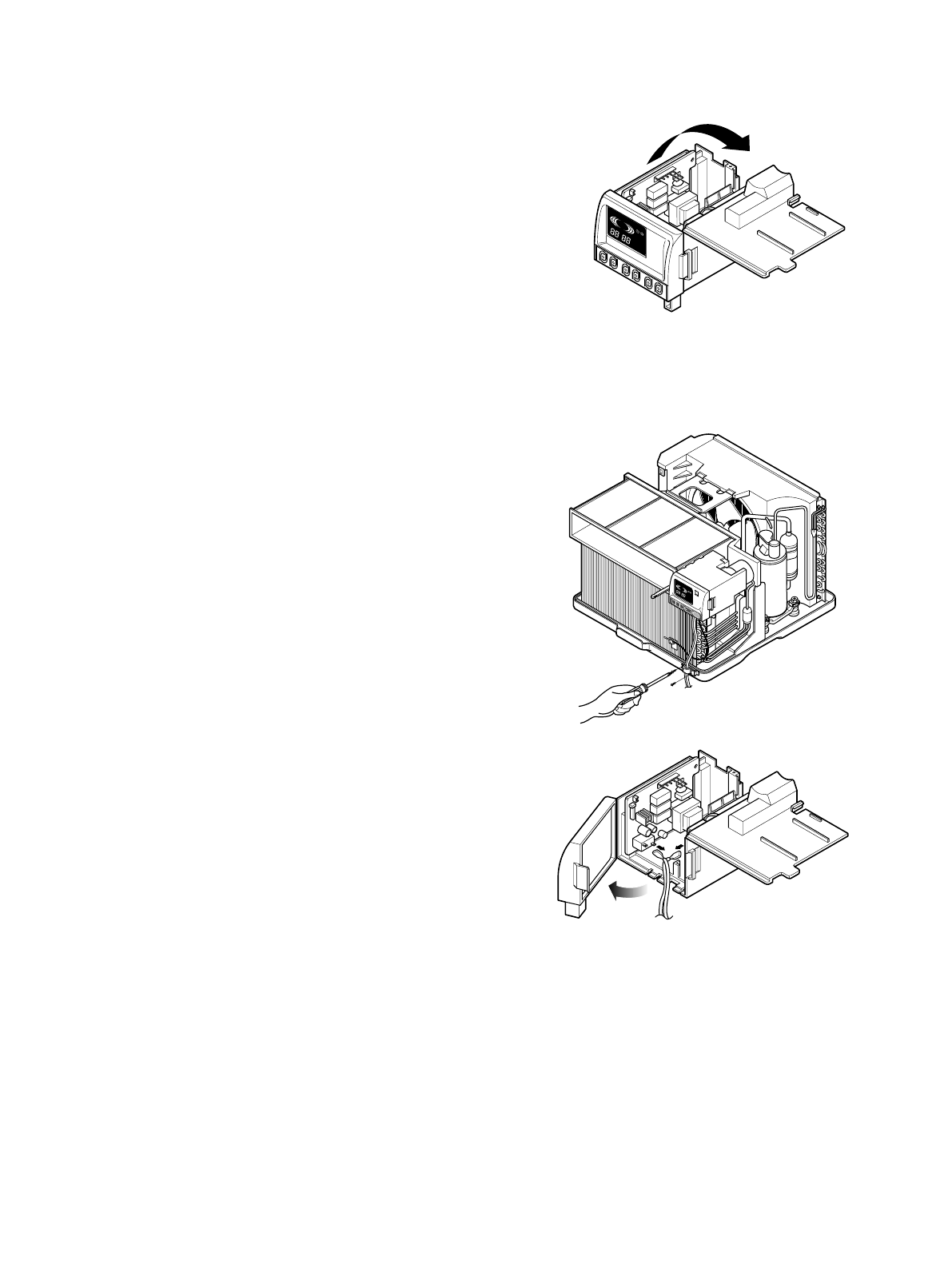
2.3.3 CAPACITOR
1. Remove the control box. (Refer to section 2.1.3)
2. Open the top cover from the control box.
(See Figure 11)
3. Pull out the capacitor from the control box.
4. Disconnect all the leads of capacitor terminals.
5. Re-install the components by referring to the
removal procedure, above.
2.3.4 POWER CORD
1. Remove the control box. (Refer to section 2.1.3)
2. Open the top cover from the control box.
(Refer to section 2.3.3)
3. Disconnect the front panel from the control box.
(See Figure 12)
4. Disconnect the 2 receptacles and remove the
grounding screw.
5. Pull out the power cord.
6. Re-install the component by referring to the
removal procedure, above.
(Use only one ground-marked hole for ground
connection.)
7. If the supply cord of this appliance is damaged, it
must be replaced by the factory specifiled cord.
DEFROST
HEAT
COOL
INDOORDESIRED
ENERGY
SAVER
AIR
PURYFIER
AUTO
RESTART
FAN
FAN
DRY
TIMEMODETEMPPOWER
FAN
SPEED
COOL
INDOORDESIRED
ENERGY
SAVER
AIR
PURYFIER
AUTO
RESTART
FAN
FAN
DRY HEAT
DEFROST
Figure 12
Figure 11
—10—
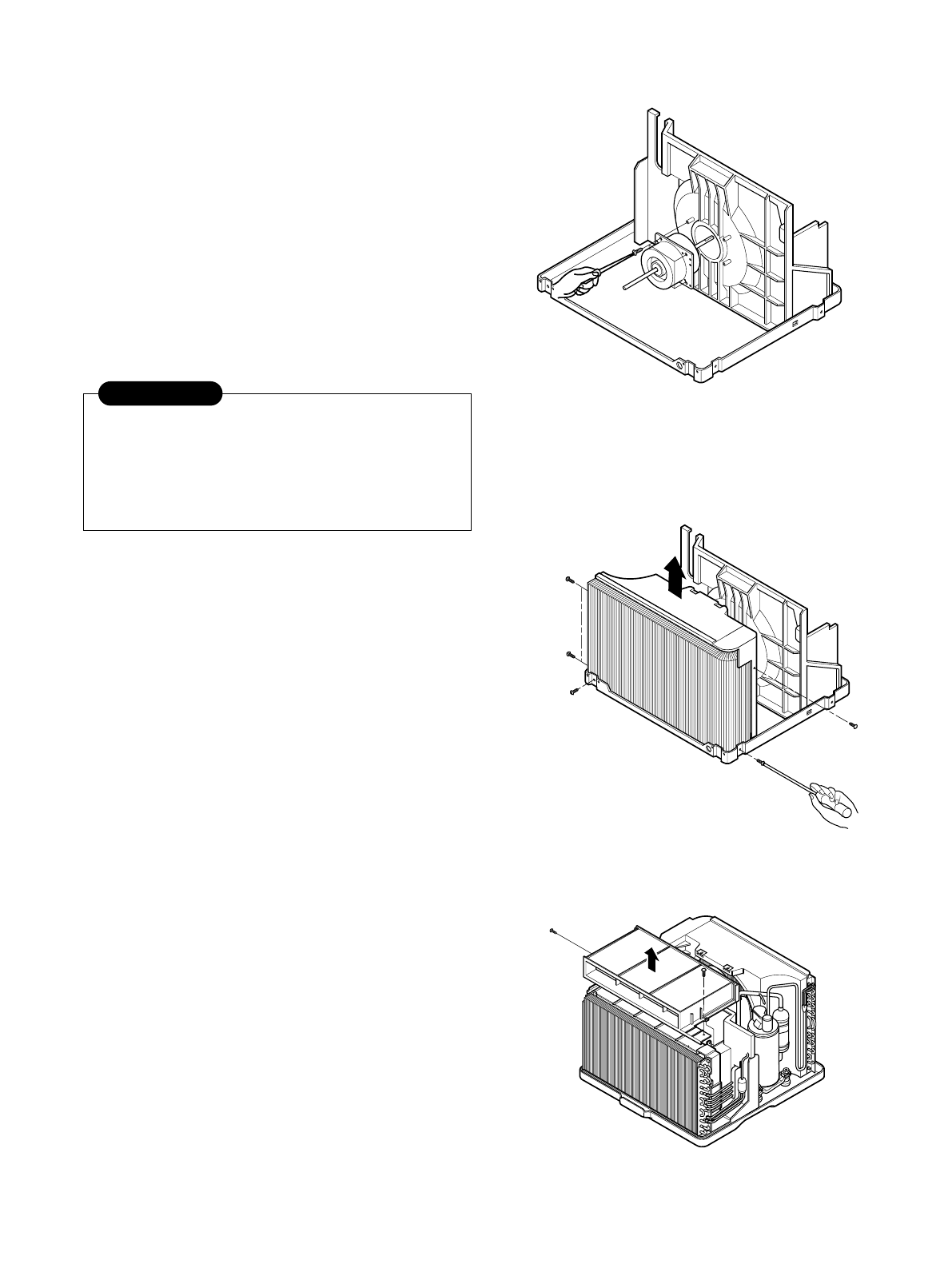
2.3.5 MOTOR
1. Remove the cabinet. (Refer to section 2.1.2)
2. Remove the turbo fan. (Refer to section 2.2.1)
3. Remove the fan. (Refer to section 2.2.2)
4. Remove the 4 screws which fasten the motor to
the air guide. (See Figure 13)
5. Remove the motor.
6. Re-install the components by referring to the
removal procedure, above.(See Figure 13)
2.4 REFRIGERATING CYCLE
2.4.1 CONDENSER
1. Remove the cabinet. (Refer to section 2.1.2)
2. Remove the 5 screws which fasten the
brace.(Refer to section 2.2.1)
3. Remove the 5 screws which fasten the condenser
and shroud.
4. After discharging the refrigerant completely,
unbraze the interconnecting tube at the condenser
connections.
5. Remove the condenser.
6. Re-install the components by referring to notes.
(See Figure 14)
2.4.2 EVAPORATOR
1. Remove the control box.(Refer to section 2.1.3)
2. Remove the air guide upper. (Refer to section
2.2.1)
3. Remove the 2 screws which fasten the evaporator.
4. Move the evaporator sideways carefully.
(Refer to section 2.2.1)
5. After discharging the refrigerant completely,
unbraze the interconnecting tube at the evaporator
connections.
6. Remove the evaporator.
7. Re-install the components by referring to notes.
(See Figure 15)
Figure 13
Figure 14
Figure 15
Discharge the refrigerant system using a
FreonTM Recovery System.
If there is no valve to attach the recovery
system, install one (such as a WATCO A-1)
before venting the FreonTM. Remove the valve
when finished.
CAUTION
—11—
— Replacement of the refrigeration cycle.
1. When replacing the refrigeration cycle, be sure to
Discharge the refrigerant system using a FreonTM
recovery System.
If there is no valve to attach the recovery system,
install one (such as a WATCO A-1) before venting
the FreonTM. Remove the valve when finished.
2. After discharging the unit completely, remove the
desired component, and unbraze the pinch-off
tubes.
3. Solder service valves into the pinch-off tube ports,
leaving the valves open.
4. Solder the pinch-off tubes with Service valves.
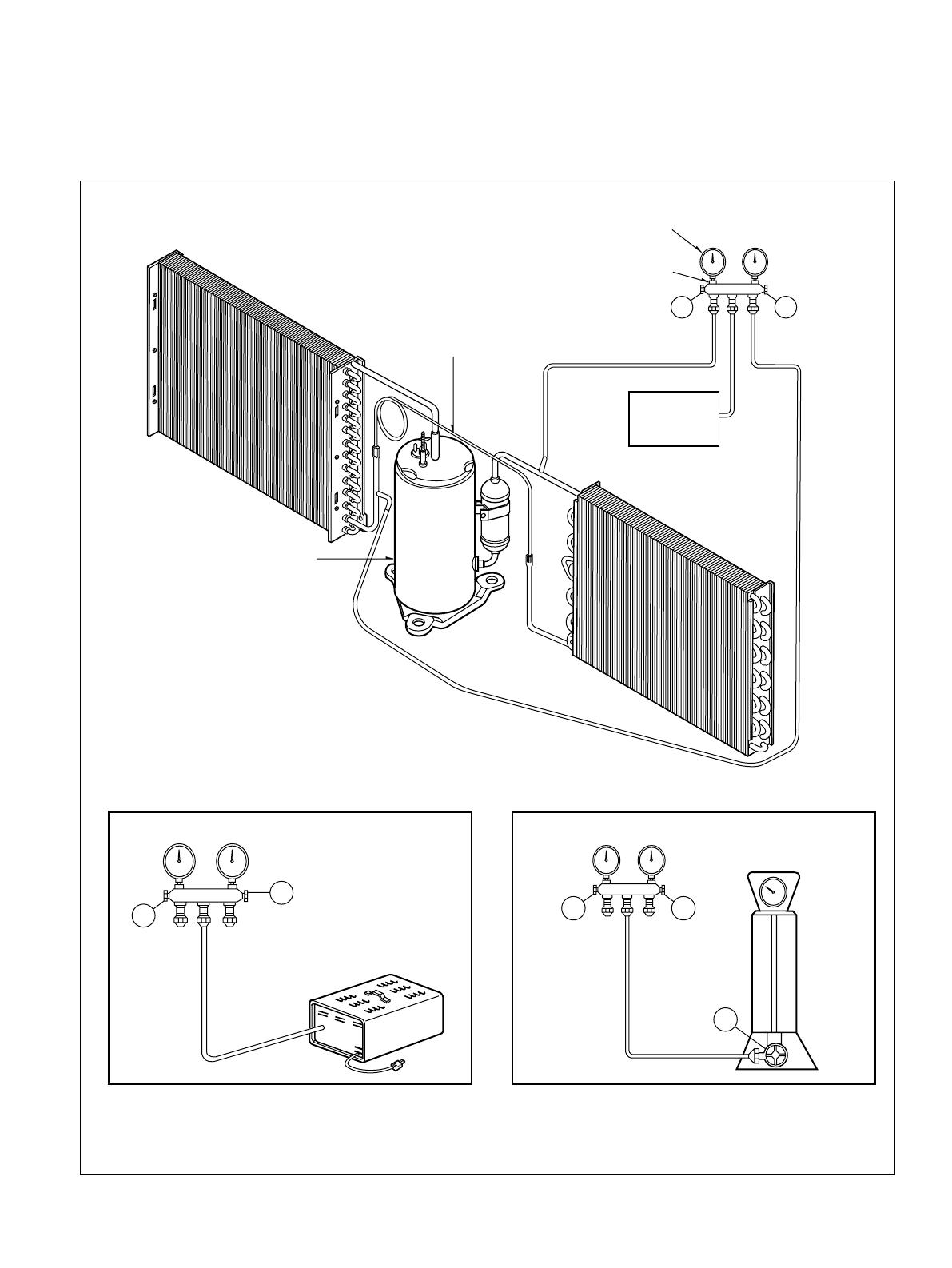
5. Evacuate as follows.
1) Connect the vacuum pump, as illustrated figure
16A.
2) Start the vacuum pump, slowly open manifold
valves A and B with two full turns
counterclockwise and leave the valves open.
The vacuum pump is now pulling through valves
A and B up to valve C by means of the manifold
and entire system.
3) Operate the vacuum pump for 20 to 30 minutes,
until 600 microns of vacuum is obtained. Close
valves A and B, and observe vacuum gauge for
a few minutes. A rise in pressure would
indicate a possible leak or moisture remaining in
the system. With valves A and B closed, stop
the vacuum pump.
4) Remove the hose from the vacuum pump and
place it on the charging cylinder. See figure
16B.
Open valve C.
Discharge the line at the manifold connection.
5) The system is now ready for final charging.
6. Recharge as follows :
1) Refrigeration cycle systems are charged from
the High-side. If the total charge cannot be put
in the High-side, the balance will be put in the
suction line through the access valve which you
installed as the system was opened.
2) Connect the charging cylinder as shown in figure
16B.
With valve C open, discharge the hose at the
manifold connection.
3) Open valve A and allow the proper charge to
enter the system. Valve B is still closed.
4) If more charge is required, the high-side will not
take it. Close valve A.
5) With the unit running, open valve B and add the
balance of the charge.
a. Do not add the liquid refrigerant to the Low-
side.
b. Watch the Low-side gauge; allow pressure to
rise to 30 lbs.
c. Turn off valve B and allow pressure to drop.
d. Repeat steps b. and c. until the balance of the
charge is in the system.
6) When satisfied the unit is operating correctly,
use the pinch-off tool with the unit still running
and clamp on to the pinch-off tube. Using a tube
cutter, cut the pinch-off tube about 2 inches from
the pinch-off tool. Use sil-fos solder and solder
pinch-off tube closed. Turn off the unit, allow it to
set for a while, and then test the leakage of the
pinch-off connection.
NOTES
If high vacuum equipment is used, just crack
valves A and B for a few minutes, then open
slowly with the two full turns counterclockwise.
This will keep oil from foaming and being
drawn into the vacuum pump.
2.4.3 CAPILLARY TUBE
1. Remove the cabinet. (Refer to section 2.1.2)
2. After discharging the refrigerant completely,
unbraze the interconnecting tube at the capillary
tube.(See caution on previous page)
3. Remove the capillary tube.
4. Re-install the components by referring to notes.
CAUTION
—12—
Equipment needed: Vacuum pump, Charging cylinder, Manifold gauge, Brazing equipment. Pinch-off tool capable
of making a vapor-proof seal, Leak detector, Tubing cutter, Hand Tools to remove components, Service valve.
A
COMPOUND GAUGE
EVAPORATOR
(LOW PRESSURE SIDE)
COMPRESSOR
CAPILLARY TUBE
CONDENSER
(HIGH PRESSURE SIDE)
SEE INSETS
BELOW
MANIFOLD
GAUGE
B
Figure 16A-Pulling Vacuum Figure 16B-Charging
A
B
EXTERNAL
VACUUM PUMP
A
CHARGING
CYLINDER
LOW HI
B
C
DEFROST
HEATCOOL
INDOOR DESIRED
ENERGY
SAVER
AIR
PURYFIER
AUTO
RESTART
FAN
FAN
DRY
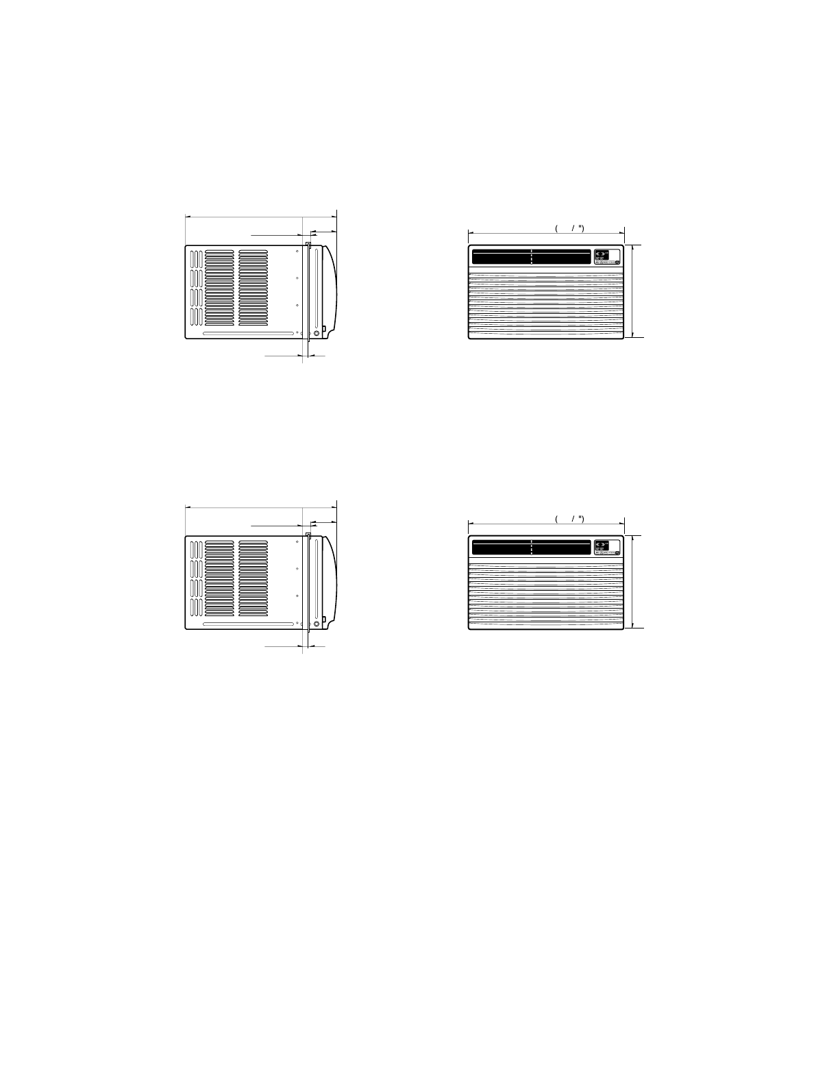
354(13 / ")
29
490(19 / )
38"
29(1 / )
532"
18( / )
23 32"
126.5(4 / )
3132"
32
510 20 332
—13—
3. TROUBLESHOOTING GUIDE
3.1 OUTSIDE DIMENSIONS
unit: mm(inch)
DEFROST
HEATCOOL
INDOOR DESIRED
ENERGY
SAVER
AIR
PURYFIER
AUTO
RESTART
FAN
FAN
DRY
380(14 / ")
31
567(22 / )
116"
29(1 / )
532"
18( / )
23 32"
111(4 / )38"
32
600 23 5 8
MODEL: ZQ08B10,CP08A10,ZQ10B10
MODEL:CP10A10,CP12A10
—14—
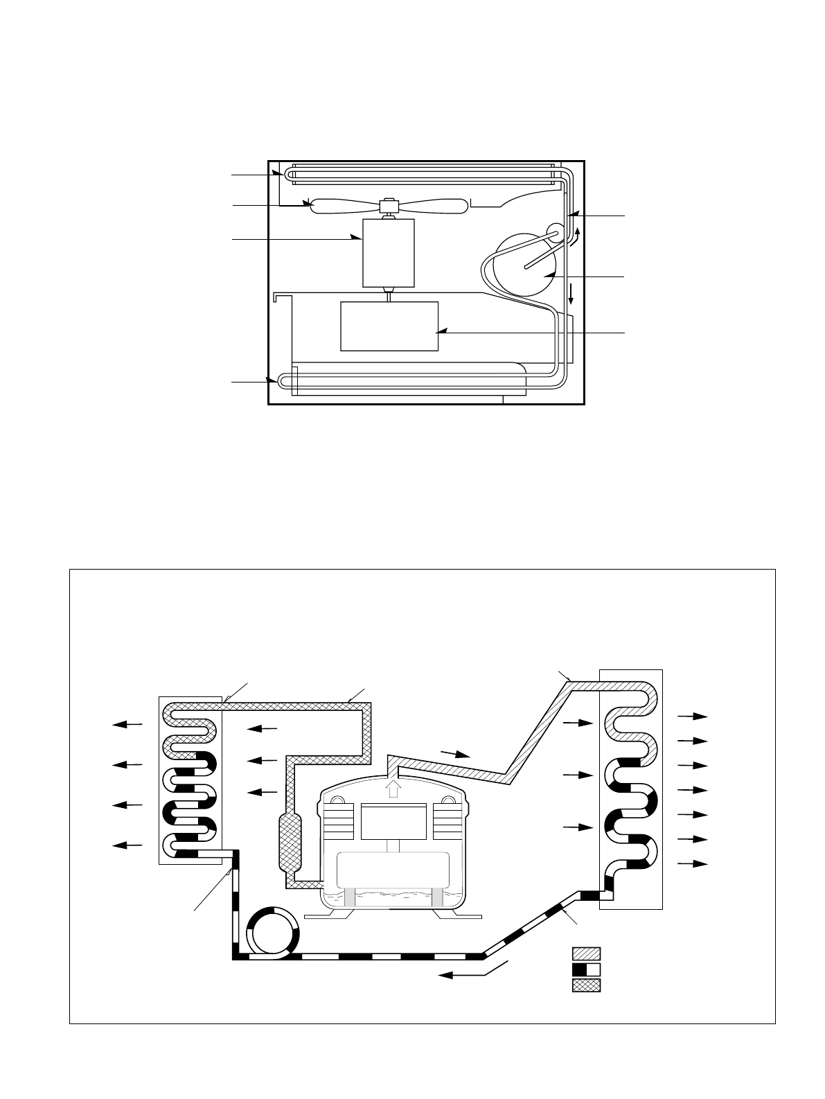
3.2 PIPING SYSTEM
Figure 17 is a brief description of the important components and their function in what is called the refrigeration
system. This will help you to understand the refrigeration cycle and the flow of the refrigerant in the cooling cycle.
MOTOR
COMPRESSOR
OIL
(LIQUID REFRIGERANT)
CAPILLARY TUBE
OUTSIDE COOLING
AIR FOR REFRIGERANT
PASS THROUGH
SUCTION LINE
COOL LOW PRESSURE VAPOR
COOLED
AIR
COMPLETE LIQUID
BOIL OFF POINT
LIQUID
PRESSURE
DROP
ROOM AIR HEAT LOAD
VAPOR INLET
HOT
DISCHARGED
AIR
LIQUID OUTLET
HIGH PRESSURE VAPOR
LIQUID REFRIGERANT
LOW PRESSURE VAPOR
ROOM AIR CONITIONER
EVAPORATOR COILS CONDENSER COILS
CYCLE OF REFRIGERATION
CAPILLARY TUBE
COMPRESSOR
TURBO FAN
CONDENSER COIL
EVAPORATOR COIL
FAN
MOTOR
Figure 17
—15—
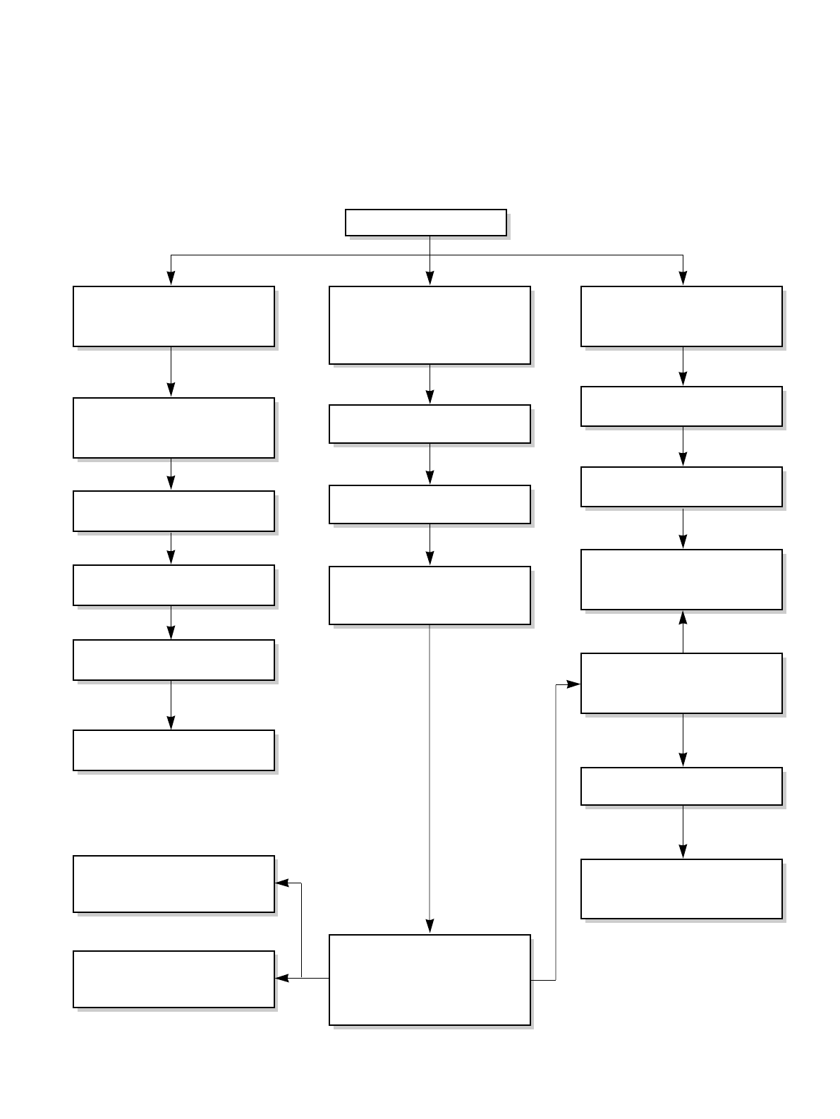
3.3 TROUBLESHOOTING GUIDE
In general, possible trouble is classified in two kinds.
The one is called Starting Failure which is caused from an electrical defect, and the other is ineffective Air
Conditioning caused by a defect in the refrigeration circuit and improper application.
Unit runs but poor cooling.
Ineffective Cooling
Check outdoor coil
(heat exchanger) & the fan
operation.
Check gas leakage.
Repair gas leak.
Replacement of unit if the
unit is beyond repair.
Satisfactory operation with
temperature difference of
inlet & outlet air ;
18~26°F.
Check heat load
increase.
Clean condenser.
Not on separate circuit.
Check inside gas
pressure.
Adjusting of refrigerant
charged.
Malfunction of compressor.
Replacement of
compressor.
Check cold air circulation
for smooth flow.
Dirty indoor coil
(Heat exchanger)
Correct above problem.
Check clogging in refrigera-
tion circuit.
Repair clogging in refrigera-
tion circuit.
Obstruction at air outlet
Clogged air filter.
Malfunction of fan
—16—
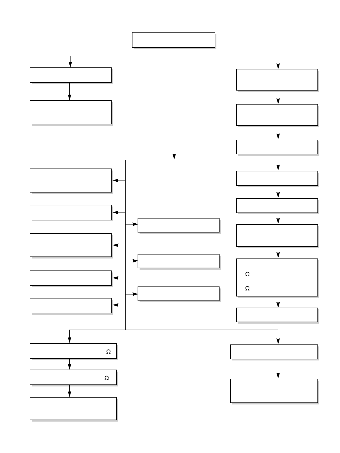
Fails to Start
Check circuit breaker
and fuse.
Gas leakage of feeler bulb
of thermostat
Check control switch.
Fan only fails to start.
Improper wiring.
Defect of fan motor
capacitor.
Irregular motor resistance
(
).
Irregular motor insulation
(
).
Replacement of fan motor.
Regular but fails to start.
Replacement of compressor
(locking of rotor, metal).
Improper thermostat setting.
Loose terminal connection.
Improper wiring.
Irregular motor resistance ( )
Irregular motor insulation (
)
Replacement of compressor
(Motor damaged)
Drop of power voltage.
Capacitor check.
Replacement
Compressor only fails to
start.
Defect of compressor
capacitor.
Check power source.
Check control switch
setting.
—17—
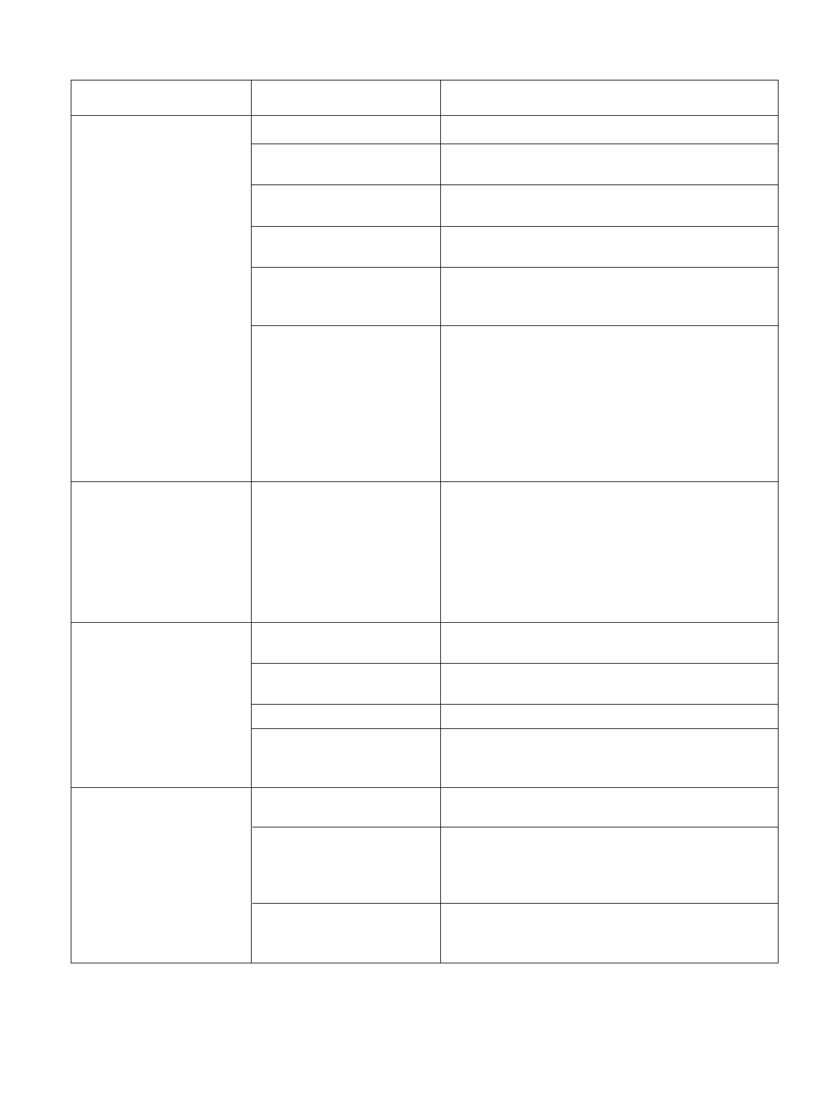
COMPLAINT CAUSE REMEDY
Check voltage at outlet. Correct if none.
Check voltage to rotary switch. If none, check power
supply cord. Replace cord if circuit is open.
Check switch continuity. Refer to wiring diagram for
terminal identification. Replace switch if defective.
Connect wire. Refer to wiring diagram for terminal
identification. Repair or replace loose terminal.
Test capacitor.
Replace if not within ±10% of manufacturer's rating.
Replace if shorted, open, or damaged.
Fan blade hitting shroud or blower wheel hitting
scroll. Realign assembly.
Units using slinger ring for condenser fan must have
1/4to 5/16 inch clearance to the base. If it hits the
base, shim up the bottom of the fan motor with
mounting screw(s).
Check fan motor bearings; if motor shaft will not
rotate, replace the motor.
Check voltage. If not within limits, call an electrician.
Test capacitor.
Check bearings. Does the fan blade rotate freely?
If not, replace fan motor.
Pay attention to any change from high speed to
low speed. If the speed does not change, replace the
motor.
If cracked, out of balance, or partially missing,
replace it.
If cracked, out of balance, or partially missing,
replace it.
Tighten it.
If knocking sounds continue when running or loose,
replace the motor. If the motor hums or noise
appears to be internal while running, replace motor.
Check voltage.
If not within limits, call an electrician.
Check the wire connections, if loose, repair or
replace the terminal. If wires are off, refer to wiring
diagram for identification, and replace. Check wire
locations. If not per wiring diagram, correct.
Check for continuity, refer to the wiring diagram for
terminal identification. Replace the switch if circuit is
open.
No power
Power supply cord
Rotary switch
Wire disconnected or
connection loose
Capacitor (Discharge
capacitor before testing.)
Will not rotate
Revolves on overload.
Fan
Blower
Loose clamper
Worn bearings
Voltage
Wiring
Rotary
Fan motor will not run.
Fan motor runs
intermittently
Fan motor noise.
Compressor will not run,
but fan motor runs.
—18—
COMPLAINT CAUSE REMEDY
Check the position of knob. If not at the coldest
setting, advance the knob to this setting and restart
unit.
Check continuity of the thermostat. Replace
thermostat if circuit is open.
Check the capacitor.
Replace if not within ±10% of manufacturers rating.
Replace if shorted, open, or damaged.
Check the compressor for open circuit or ground. If
open or grounded, replace the compressor.
Check the compressor overload, if externally
mounted. Replace if open. (If the compressor
temperature is high, remove the overload, cool it,
and retest.)
Check the voltage.
If not within limits, call an electrician.
Check overload, if externally mounted.
Replace if open. (If the compressor temperature is
high, remove the overload, cool, and retest.)
If not running, determine the cause. Replace if
required.
Remove the cabinet. inspect the interior surface of
the condenser; if restricted, clean carefully with a
vacuum cleaner (do not damage fins) or brush.
Clean the interior base before reassembling.
If condenser fins are closed over a large area on the
coil surface, head pressures will increase, causing
the compressor to overload. Straighten the fins or
replace the coil.
Test capacitor.
Check the terminals. If loose, repair or replace.
Check the system for a restriction.
If restricted, clean of replace.
Close if open.
Determine if the unit is properly sized for the area to
be cooled.
Check the set screw or clamp. If loose or missing,
correct. If the blower or fan is hitting air guide,
rearrange the air handling parts.
Remove the cabinet carefully and rearrange tubing
not to contact cabinet, compressor, shroud, and
barrier.
Thermostat
Capacitor (Discharge
capacitor before servicing.)
Compressor
Overload
Voltage
Overload
Fan motor
Condenser air flow
restriction
Condenser fins (damaged)
Capacitor
Wiring
Refrigerating system
Air filter
Exhaust damper door
Unit undersized
Blower or fan
Copper tubing
Compressor will not run,
but fan motor runs.
Compressor cycles on
overload.
Compressor cycles on
overload.
Compressor cycles on
overload.
Insufficient cooling or
heating
Excessive noise
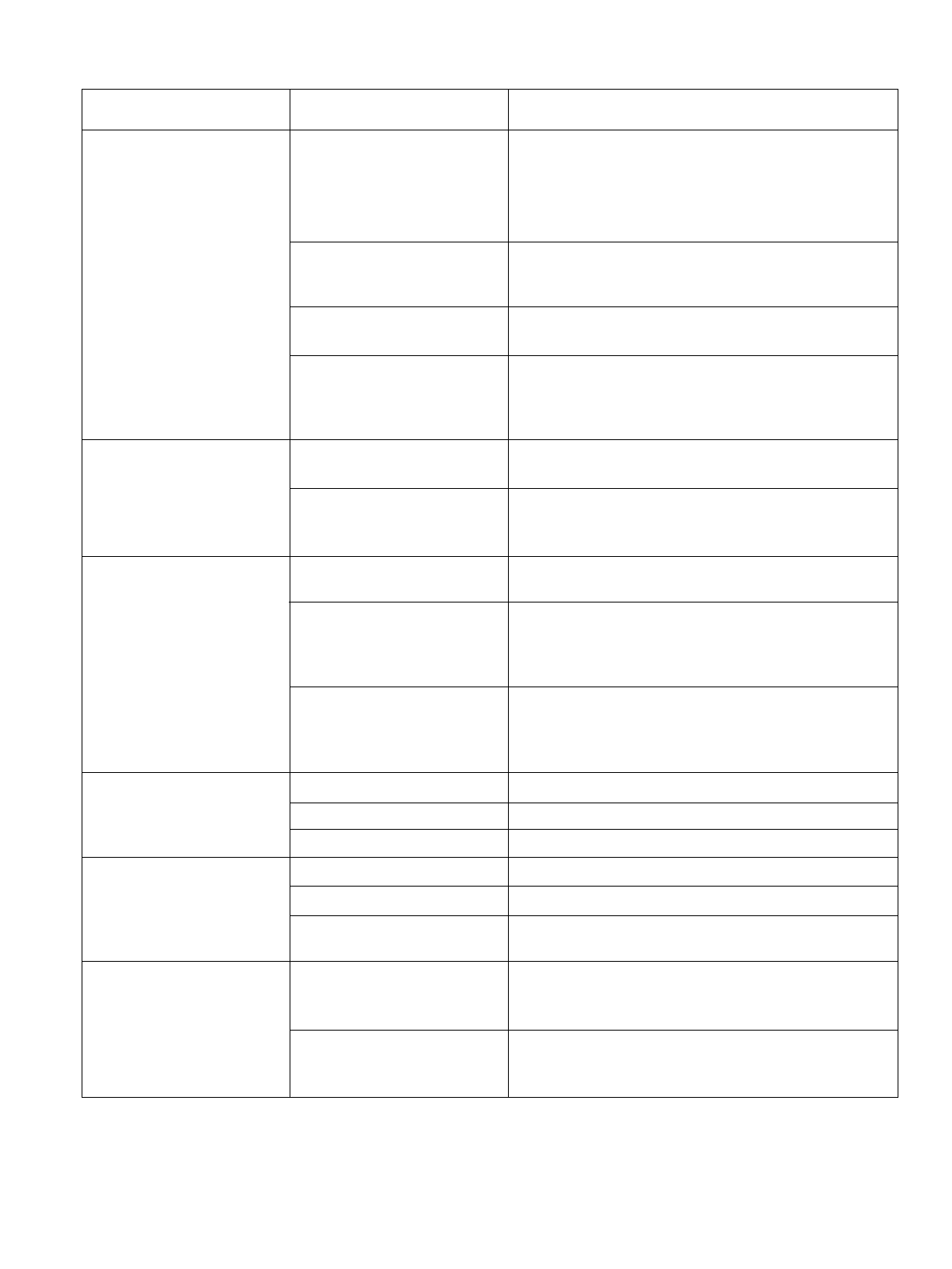
MOTOR ASSY
CAPACITOR
COMPRESSOR
OVERLOAD PROTECTOR
DC PCB ASSEMBLY
AC PCB ASSEMBLY
THERMISTOR
THERMOSTAT
ROTARY SWITCH
1
2
3
4
5
6
7
8
9
1
1
1
1
1
1
1
1
1
S
S
S
S
S
S
S
S
S
LOCATION
NO.
DESCRIPTION
RE-
MARKS
Q'TY
PER SET
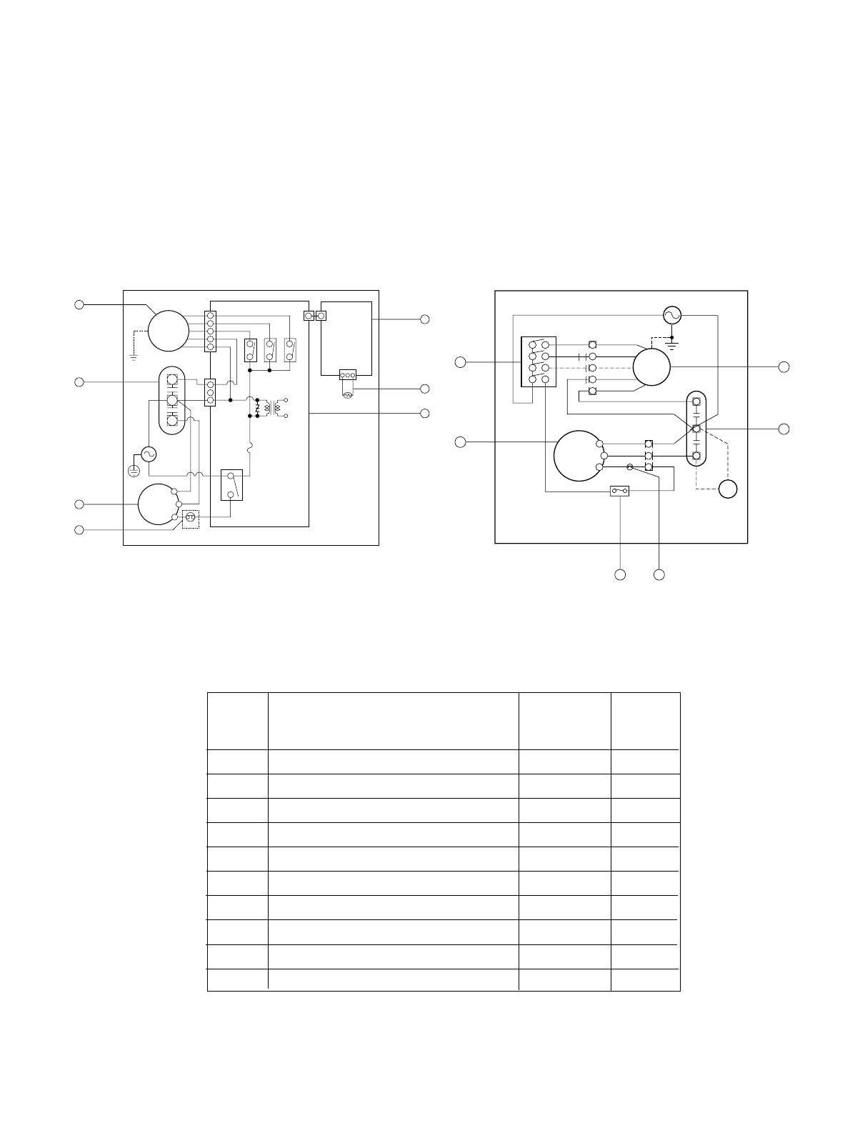
4. SCHEMATIC DIAGRAM
—19—
MOTOR
COMP.
CAPACITOR
DC PCB
ASSEMBLY
THERMISTOR
AC PCB
ASSEMBLY
WIRING DIAGRAM 3854AR3563N
BK
CN-MOTOR
CN-PWR
ZNR01J
RY-COMP
3
4
FUSE
250V/T2A
(115V/T2A)
RY-LOW
RY-MED
RY-HI
CN-AC/DC
POWER
TRANS
CN-AC/DC
CN-TH1
BL
RD
BL
R
S
C
OLP
YL
OR
YL
F
C
H
WH(BL)
(Ribbed)
BK(BR)
(Plain)
GN/YL
(GN)
GN/YL
(GN)
BK
RD
OR
(
BR
)
1
5
7
6
4
2
3
COMP.
MOTOR
WH(BL)
POWER INPUT
(Plain)
GN(GN/YL)
BK(BR)
(Ribbed)
WIRING DIAGRAM 3854AR3563A
BL
BL
RD
BK
R
C
S
YL
YL
RD
BK
BL
RD
ROTARY SWITCH
BK
BL
L7
1
8
6
4
2
H
M
OR(BR)
OR(BR)
BL
RD
BK
THERMOSTAT
CAPACITOR
P.T.C
RD
BK
F
C
H
BR(YL)
OLP
9
3
2
1
84
S: Service Parts
N: Non Service Parts
MODEL: CP08A10, CP10A10, CP12A10
MODEL: ZQ08B10,ZQ10B10
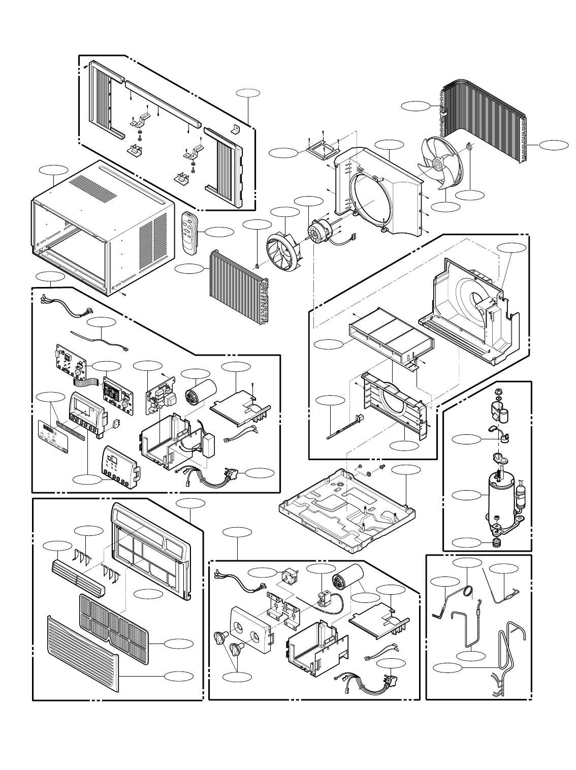
5. EXPLODED VIEW
—20—
130910
149980
346811
359012
W48602
349001
352390-2
352390-1
W0CZZ 135500
147581
147582-2
559011
349480
352113
352113
W48602
148000
354210
152302
264110
249950
149410
266003
269310
130410
550140
35211A
554160
567502
135312
135313
554031
352115
552111
268714 W0CZZ 135500
249950
263230
268712
238310
264110
237200
731373
267110
554030
147582-1
—21—
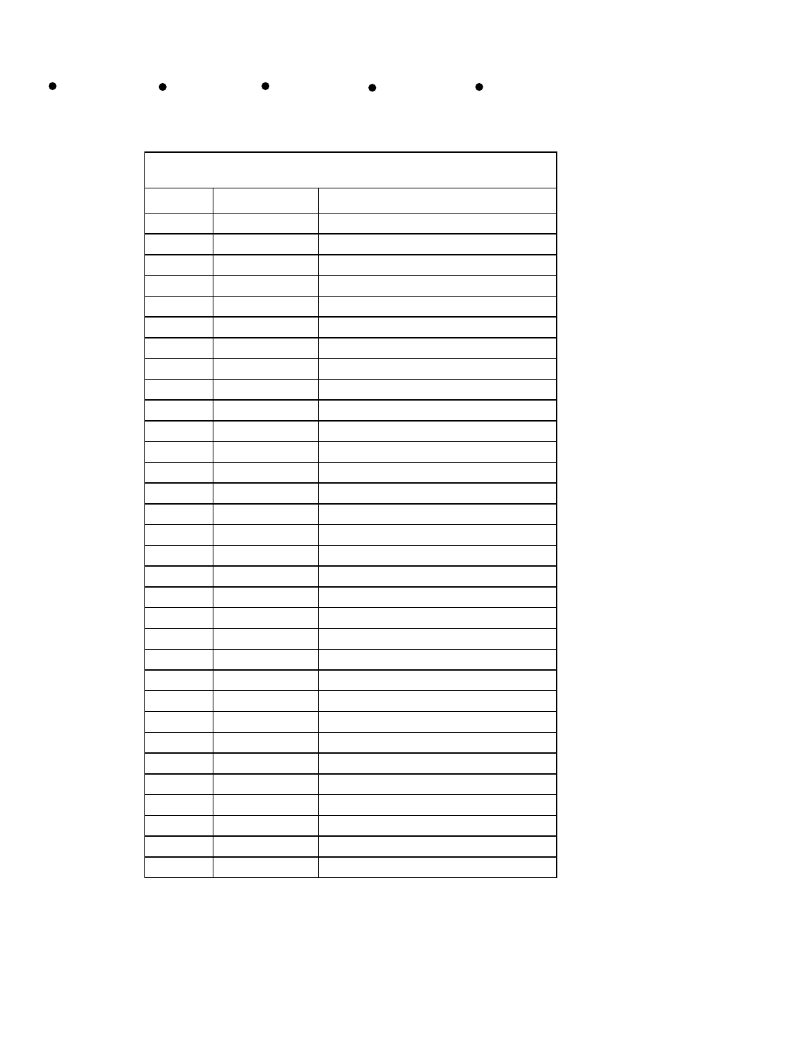
6. REPLACEMENT PARTS LIST R: Service Parts
N: Non Service Parts
ZQ08B10 ZQ10B10 CP08A10 CP10A10 CP12A10
Loc No FRIEDRICH Description
130410 67302924 BASE ASSEMBLY,SINGLE
130910 67303711 CABINET ASSEMBLY,SINGLE
135312 67306014 GRILLE ASSEMBLY,FRONT(SINGLE)
135313 67306109 GRILLE,INLET
135500 67300311 COVER
147581 67306207 LOUVER,HORIZONTAL
147582-1 67306260 LOUVER,VERTICAL
147582-2 67306261 LOUVER,VERTICAL
148000 67303909 BRACE
149410 67304105 KNOB ASSEMBLY
149980 67303114 SHROUD
152302 67304306 FILTER ASSEMBLY,AIR CLEANER
237200 67305509 PANEL ASSEMBLY,CONTROL
264110 67300017 POWER CORD ASSEMBLY
266003 67300501 SWITCH,ROTARY
269310 67300402 THERMOSTAT ASSEMBLY
346811 67303031 MOTOR ASSEMBLY,SINGLE
349001 67303507 DAMPER,VENTILATION
349480 67303408 ORIFICE
352390-1 67302718 AIR GUIDE ASSEMBLY
352390-2 67302731 AIR GUIDE ASSEMBLY
354210 67302427 EVAPORATOR ASSEMBLY,FIRST
359012 67302611 FAN,TURBO
550140 67301901 ISOLATOR,COMP
552111 67302124 TUBE ASSEMBLY,CAPILLARY
554030 67303324 CONDENSER ASSEMBLY,FIRST
554160 67500121 COMPRESSOR SET,CHINA
559011 67303201 FAN ASSEMBLY,AXIAL
567502 67301417 O.L.P
731373 67306309 INSTALL PART ASSEMBLY,SINGLE
W0CZZ 67300718 CAPACITOR,DRAWING
W48602 67302500 CLAMP,SPRING
ZQ08B10

—22—
Loc No FRIEDRICH Description
130410 67302913 BASE ASSEMBLY,SINGLE
130910 67303711 CABINET ASSEMBLY,SINGLE
135312 67306014 GRILLE ASSEMBLY,FRONT(SINGLE)
135313 67306109 GRILLE,INLET
135500 67300311 COVER
147581 67306207 LOUVER,HORIZONTAL
147582-1 67306260 LOUVER,VERTICAL
147582-2 67306261 LOUVER,VERTICAL
148000 67303909 BRACE
149410 67304105 KNOB ASSEMBLY
149980 67303110 SHROUD
152302 67304306 FILTER ASSEMBLY,AIR CLEANER
237200 67305509 PANEL ASSEMBLY,CONTROL
249950 67305322 CONTROL BOX ASSEMBLY,SINGLE
264110 67300019 POWER CORD ASSEMBLY
266003 67300501 SWITCH,ROTARY
269310 67300402 THERMOSTAT ASSEMBLY
346811 67303032 MOTOR ASSEMBLY,SINGLE
349001 67303507 DAMPER,VENTILATION
349480 67303408 ORIFICE
352113 67302309 TUBE ASSEMBLY,DISCHARGE SINGLE
352115 67302019 TUBE ASSEMBLY,EVAPORATOR IN
35211A 67302220 TUBE ASSEMBLY,SUCTION SINGLE
352390-1 67302718 AIR GUIDE ASSEMBLY
352390-2 67302731 AIR GUIDE ASSEMBLY
354210 67302428 EVAPORATOR ASSEMBLY,FIRST
359012 67302611 FAN,TURBO
550140 67301901 ISOLATOR,COMP
552111 67302125 TUBE ASSEMBLY,CAPILLARY
554031 67303315 CONDENSER ASSEMBLY,BENT
554160 67500122 COMPRESSOR SET,CHINA
559011 67303201 FAN ASSEMBLY,AXIAL
567502 67301409 O.L.P
731373 67306309 INSTALL PART ASSEMBLY,SINGLE
W0CZZ 67300716 CAPACITOR,DRAWING
W48602 67302500 CLAMP,SPRING
ZQ10B10

—23—
Loc No FRIEDRICH Description
130410 67302913 BASE ASSEMBLY,SINGLE
130910 67303711 CABINET ASSEMBLY,SINGLE
135312 67306014 GRILLE ASSEMBLY,FRONT(SINGLE)
135313 67306109 GRILLE,INLET
135500 67300310 COVER
147581 67306207 LOUVER,HORIZONTAL
147582-1 67306260 LOUVER,VERTICAL
147582-2 67306261 LOUVER,VERTICAL
148000 67303909 BRACE
149980 67303110 SHROUD
152302 67304306 FILTER ASSEMBLY,AIR CLEANER
237200 67305508 PANEL,CONTROL
238310 67500116 ESCUTCHEON
263230 67307807 THERMISTOR ASSEMBLY
264110 67300017 POWER CORD ASSEMBLY
267110 67307701 REMOTE CONTROLLER ASSEMBLY
268712 67307614 PWB(PCB) ASSEMBLY,MAIN(DC)
268714 67307613 PWB(PCB) ASSEMBLY,MAIN(AC)
346811 67303018 MOTOR ASSEMBLY,SINGLE
349001 67303507 DAMPER,VENTILATION
349480 67303408 ORIFICE
352390-1 67302718 AIR GUIDE ASSEMBLY
352390-2 67302731 AIR GUIDE ASSEMBLY
354210 67302426 EVAPORATOR ASSEMBLY,FIRST
359012 67302611 FAN,TURBO
550140 67301901 ISOLATOR,COMP
552111 67302123 TUBE ASSEMBLY,CAPILLARY
554031 67303315 CONDENSER ASSEMBLY,BENT
554160 67500120 COMPRESSOR SET,CHINA
559011 67303201 FAN ASSEMBLY,AXIAL
567502 67301406 O.L.P
731373 67306309 INSTALL PART ASSEMBLY,SINGLE
W0CZZ 67300718 CAPACITOR,DRAWING
W48602 67302500 CLAMP,SPRING
CP08A10

—24—
Loc No FRIEDRICH Description
130410 67302923 BASE ASSEMBLY,SINGLE
130910 67303710 CABINET ASSEMBLY,SINGLE
135312 67306013 GRILLE ASSEMBLY,FRONT(SINGLE)
135313 67306108 GRILLE,INLET
135500 67300310 COVER
147581 67306206 LOUVER,HORIZONTAL
147582-1 67306258 LOUVER,VERTICAL
147582-2 67306259 LOUVER,VERTICAL
148000 67303908 BRACE
149980 67303113 SHROUD
152302 67304307 FILTER ASSEMBLY,AIR CLEANER
237200 67305508 PANEL,CONTROL
238310 67500116 ESCUTCHEON
263230 67307807 THERMISTOR ASSEMBLY
264110 67300019 POWER CORD ASSEMBLY
267110 67307701 REMOTE CONTROLLER ASSEMBLY
268712 67307613 PWB(PCB) ASSEMBLY,MAIN(AC)
268714 67307614 PWB(PCB) ASSEMBLY,MAIN(DC)
346811 67303030 MOTOR ASSEMBLY,SINGLE
349001 67303506 DAMPER,VENTILATION
349480 67303411 ORIFICE
352390-1 67302729 AIR GUIDE ASSEMBLY
352390-2 67302730 AIR GUIDE
354210 67302425 EVAPORATOR ASSEMBLY,FIRST
359012 67302615 FAN,TURBO
550140 67301901 ISOLATOR,COMP
552111 67302122 TUBE ASSEMBLY,CAPILLARY
554030 67303323 CONDENSER ASSEMBLY,FIRST
554160 67500119 COMPRESSOR SET,CHINA
559011 67302614 FAN,AXIAL
567502 67301409 O.L.P
731373 67306308 INSTALL PART ASSEMBLY,SINGLE
W0CZZ 67300716 CAPACITOR,DRAWING
W48602 67302500 CLAMP,SPRING
CP10A10

—25—
Loc No FRIEDRICH Description
130410 67302922 BASE ASSEMBLY,SINGLE
130910 67303710 CABINET ASSEMBLY,SINGLE
135312 67306013 GRILLE ASSEMBLY,FRONT(SINGLE)
135313 67306108 GRILLE,INLET
135500 67300310 COVER
147581 67306206 LOUVER,HORIZONTAL
147582-1 67306258 LOUVER,VERTICAL
147582-2 67306259 LOUVER,VERTICAL
148000 67303908 BRACE
149980 67303112 SHROUD ASSEMBLY
152302 67304307 FILTER ASSEMBLY,AIR CLEANER
237200 67305508 PANEL,CONTROL
238310 67500116 ESCUTCHEON
263230 67307807 THERMISTOR ASSEMBLY
264110 67300018 POWER CORD ASSEMBLY
267110 67307701 REMOTE CONTROLLER ASSEMBLY
268712 67307613 PWB(PCB) ASSEMBLY,MAIN(AC)
268714 67307614 PWB(PCB) ASSEMBLY,MAIN(DC)
346811 67303029 MOTOR ASSEMBLY,SINGLE
349001 67303506 DAMPER,VENTILATION
349480 67303411 ORIFICE
352390-1 67302729 AIR GUIDE ASSEMBLY
352390-2 67302730 AIR GUIDE
354210 67302424 EVAPORATOR ASSEMBLY,FIRST
359011 67302614 FAN,AXIAL
359012 67302615 FAN,TURBO
550140 67301901 ISOLATOR,COMP
552111 67302121 TUBE ASSEMBLY,CAPILLARY
554031 67303322 CONDENSER ASSEMBLY,BENT
554160 67500118 COMPRESSOR SET,CHINA
567502 67301416 O.L.P
731373 67306308 INSTALL PART ASSEMBLY,SINGLE
W0CZZ 67300716 CAPACITOR,DRAWING
CP12A10

—26—
MEMO

—27—
MEMO

Post Office Box 1540 • 4200 N. Pan Am Expressway • San Antonio, Texas 78295-1540
• (210) 357-4400 • FAX (210) 357-4490
FRIEDRICH AIR CONDITIONING CO.
Visit our web site at www.friedrich.com
Use Factory Certified Parts...
