Friedrich Kuhl R 410A Users Manual RAC Standard Chassis IO_(06 12 10)_CS3
17073 1506430852 2010 Kuhl Service Manual 17073_1506430852_2010_Kuhl_Service_Manual 17073_1506430852_2010_Kuhl_Service_Manual 17 staging productuploader-uploads 3:
17073 1508463035 2010 Kuhl Service Manual 17073_1508463035_2010_Kuhl_Service_Manual 17073_1508463035_2010_Kuhl_Service_Manual 17 staging productuploader-uploads 3:
17073 1507024346 2010 Kuhl Service Manual 17073_1507024346_2010_Kuhl_Service_Manual 17073_1507024346_2010_Kuhl_Service_Manual 17 staging productuploader-uploads 3:
17073 1507290014 2010 Kuhl Service Manual 17073_1507290014_2010_Kuhl_Service_Manual 17073_1507290014_2010_Kuhl_Service_Manual 17 staging productuploader-uploads 3:
17073 1507801126 2010 Kuhl Service Manual 17073_1507801126_2010_Kuhl_Service_Manual 17073_1507801126_2010_Kuhl_Service_Manual 17 staging productuploader-uploads 3:
2015-02-02
: Friedrich Friedrich-Kuhl-R-410A-Users-Manual-428401 friedrich-kuhl-r-410a-users-manual-428401 friedrich pdf
Open the PDF directly: View PDF ![]() .
.
Page Count: 87
Service Manual
Standard Chassis R-410A Models
Room Air Conditioners
115-Volt:
208-230-Volt:
Cool Only
SS08M10, SS10M10, SS12M10, SS14M10
SS12M30, SS15M30, SM18M30, SM21M30
SM24M30, SL28M30, SL36M30
Cool with Electric Heat
208-230-Volt: ES12M33, ES15M33, EM18M34, EM24M35, EL36M35
Heat Pump with Electric Heat
208-230-Volt: YS12M33, YM18M34, YL24M35
Heat Pump
115-Volt: YS10M10
SYSTEM FAN MODE
SCHEDULE FAN SPEED
AUTO
AUTO
AUTO
CONTINUOUS
°F °C
Kuhl-ServMan (5-10)
1
Table Of Contents
Important Safety Information ..................................................................................................................................... 2-4
Introduction ................................................................................................................................................................... 5
Model and Serial Number Location .............................................................................................................................. 5
Unit Identifi cation .......................................................................................................................................................... 6
Performance Data and Specifi cations .......................................................................................................................... 7
Installation Information/Sleeve Dimensions/Circuit Rating ........................................................................................... 8
Electrical Data ............................................................................................................................................................... 9
Before Operating the Unit ............................................................................................................................................10
Control Panel Operation ..............................................................................................................................................11
Alerts ......................................................................................................................................................................12-14
Remote Control Operation ......................................................................................................................................15-16
Electronic Control System Maintenance Operation .................................................................................................17-20
Unit Operation .............................................................................................................................................................. 21
Cool-Heat Set Points .................................................................................................................................................. 22
Electronic Control Sequence of Operation ............................................................................................................ 23-29
Unit Operation with a Wall-Stat ................................................................................................................................... 29
Removing the Front Cover and Unit Chassis ................................................................................................................ 30
Replacing the ID Coil Thermistor ................................................................................................................................ 31
Replacing the Control Board ....................................................................................................................................... 31
Low Voltage Interface Connector ................................................................................................................................ 32
Replacing the ID Coil Thermistor ................................................................................................................................ 31
Remote Wall Thermostat ....................................................................................................................................... 32-33
Airfl ow Selection and Adjustment ............................................................................................................................... 33
Components Testing .............................................................................................................................................. 34-35
Refrigeration Sequence of Operation .................................................................................................................... 36-37
Sealed Refrigeration System Repairs ................................................................................................................... 38-41
Hermetics Components Check ................................................................................................................................... 42
Reversing Valve Description/Operation ...................................................................................................................... 43
Testing the Coil ........................................................................................................................................................... 44
Checking the Reversing Valve ............................................................................................................................... 44-45
Compressor Checks .............................................................................................................................................. 46-47
Compressor Replacement ..................................................................................................................................... 48-49
Routine Maintenance / Battery Check / Change ...................................................................................................... 50-53
Service and Assistance ............................................................................................................................................... 54
Performance Test Data Sheet and Sizing Guide .......................................................................................................... 55
Error Codes and Alarm Status .................................................................................................................................... 56
Troubleshooting ..................................................................................................................................................... 57-66
Electronic Control Board Components Identifi cation ................................................................................................... 67
Wiring Diagrams .................................................................................................................................................... 68-75
Thermistors' Resistance Values .................................................................................................................................. 76
Remote Control Replacement Instructions ........................................................................................................... 77-78
User Interface Service Kit ........................................................................................................................................... 79
Instructions for Using Cooling Load Estimate Form ................................................................................................... 80
Cooling Load Estimate Form ...................................................................................................................................... 81
Heat Load Form .................................................................................................................................................... 82-83
Warranty ..................................................................................................................................................................... 84
2
IMPORTANT SAFETY INFORMATION
The information contained in this manual is intended for use by a qualifi ed service technician who is familiar
with the safety procedures required for installation and repair, and who is equipped with the proper tools
and test instruments required to service this product.
Installation or repairs made by unqualifi ed persons can result in subjecting the unqualifi ed person making
such repairs as well as the persons being served by the equipment to hazards resulting in injury or
electrical shock which can be serious or even fatal.
Safety warnings have been placed throughout this manual to alert you to potential hazards that may be
encountered. If you install or perform service on equipment, it is your responsibility to read and obey these
warnings to guard against any bodily injury or property damage which may result to you or others.
PERSONAL INJURY OR DEATH HAZARDS
ELECTRICAL HAZARDS:
Unplug and/or disconnect all electrical power to the unit before performing inspections, •
maintenance, or service.
M• ake sure to follow proper lockout/tag out procedures.
A• lways work in the company of a qualifi ed assistant if possible.
C• apacitors, even when disconnected from the electrical power source, retain an electrical charge
potential capable of causing electric shock or electrocution.
H• andle, discharge, and test capacitors according to safe, established, standards, and approved
procedures.
E• xtreme care, proper judgment, and safety procedures must be exercised if it becomes necessary
to test or troubleshoot equipment with the power on to the unit.
Your safety and the safety of others are very important.
We have provided many important safety messages in this manual and on your appliance. Always read
and obey all safety messages.
All safety messages will tell you what the potential hazard is, tell you how to reduce the chance of injury,
and tell you what will happen if the instructions are not followed.
This is a Safety Alert symbol.
This symbol alerts you to potential hazards that can kill or hurt you and others.
All safety messages will follow the safety alert symbol with the word “WARNING”
or “CAUTION”. These words mean:
You can be killed or seriously injured if you do not follow instructions.
You can receive minor or moderate injury if you do not follow instructions.
A message to alert you of potential property damage will have the
word “NOTICE”. Potential property damage can occur if instructions
are not followed.
WARNING
CAUTION
NOTICE
3
D• o not spray or pour water on the return air grille, discharge air grille, evaporator coil, control panel,
and sleeve on the room side of the air conditioning unit while cleaning.
E• lectrical component malfunction caused by water could result in electric shock or other electrically
unsafe conditions when the power is restored and the unit is turned on, even after the exterior is dry.
N• ever operate the A/C unit with wet hands.
U• se air conditioner on a single dedicated circuit within the specifi ed amperage rating.
U• se on a properly grounded outlet only.
D• o not remove ground prong of plug.
D• o not cut or modify the power supply cord.
D• o not use extension cords with the unit.
F• ollow all safety precautions and use proper and adequate protective safety aids such as: gloves,
goggles, clothing, adequately insulated tools, and testing equipment etc.
F• ailure to follow proper safety procedures and/or these warnings can result in serious injury or death.
REFRIGERATION SYSTEM REPAIR HAZARDS:
U• se approved standard refrigerant recovering procedures and equipment to relieve pressure before
opening system for repair.
D• o not allow liquid refrigerant to contact skin. Direct contact with liquid refrigerant can result in minor
to moderate injury.
B• e extremely careful when using an oxy-acetylene torch. Direct contact with the torch’s fl ame or hot
surfaces can cause serious burns.
M• ake sure to protect personal and surrounding property with fi re proof materials.
Have a fi re extinguisher at hand while using a torch.•
Pr• ovide adequate ventilation to vent off toxic fumes, and work with a qualifi ed assistant whenever
possible.
A• lways use a pressure regulator when using dry nitrogen to test the sealed refrigeration system for
leaks, fl ushing etc.
M• ake sure to follow all safety precautions and to use proper protective safety aids such as: gloves,
safety glasses, clothing etc.
F• ailure to follow proper safety procedures and/or these warnings can result in serious injury or death.
MECHANICAL HAZARDS:
E• xtreme care, proper judgment and all safety procedures must be followed when testing,
troubleshooting, handling, or working around unit with moving and/or rotating parts.
B• e careful when, handling and working around exposed edges and corners of the sleeve, chassis,
and other unit components especially the sharp fi ns of the indoor and outdoor coils.
U• se proper and adequate protective aids such as: gloves, clothing, safety glasses etc.
F• ailure to follow proper safety procedures and/or these warnings can result in serious injury or death.
4
PROPERTY DAMAGE HAZARDS
FIRE DAMAGE HAZARDS:
R• ead the Installation/Operation Manual for the air conditioning unit prior to operating.
U• se air conditioner on a single dedicated circuit within the specifi ed amperage rating.
Connect to a properly grounded outlet only.•
D• o not remove ground prong of plug.
D• o not cut or modify the power supply cord.
D• o not use extension cords with the unit.
Be extremely careful when using acetylene torch and protect surrounding property.•
Fa• ilure to follow these instructions can result in fi re and minor to serious property damage.
WATER DAMAGE HAZARDS:
I• mproper installation, maintenance or servicing of the air conditioner unit can result in water damage
to personal items or property.
In• sure that the unit has a suffi cient pitch to the outside to allow water to drain from the unit.
D• o not drill holes in the bottom of the drain pan or the underside of the unit.
F• ailure to follow these instructions can result in damage to the unit and/or minor to serious property
damage.
5
This service manual is designed to be used in conjunction with the installation and operation manuals provided with
each air conditioning system.
This service manual was written to assist the professional RAC (Room Air Conditioner) service technician to quickly
and accurately diagnose and repair malfunctions.
This manual will deal with subjects in a general nature.
IMPORTANT: It will be necessary for you to accurately identify the unit you are servicing, so you can be certain of a
proper diagnosis and repair (See Unit Identifi cation code on page 6).
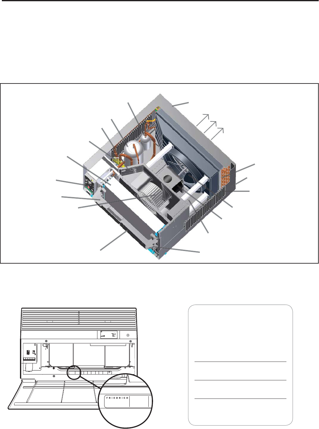
INTRODUCTION
Compressor
Fresh Air Vent
Evaporator Coil
Electronic Control
Board
Control Key Pad
Support Bar
Blower Wheel
Air Intake From
Sides and Bottom
Control Key Pad
(User Interface) Chassis Pull
Out Handle
Base Pan
Fan Blade
Fan/Blower Motor
Air Intake Vents
Sleeve
Condenser Coil
Discharge Air
Outdoor Grille
Accumulator
Reversing Valve
Model information can be found on the
name plate behind the front cover.
For your future con ve nience, record
the model information here.
MODEL NUMBER
SERIAL NUMBER
PURCHASE DATE
Register the air conditioner
MODEL NUMBER
YS10M10A
SERIAL NUMBER
LICY00008
VOLTS 115
60 HZ / 1 PH
VOLTS MIN 108
COOLING
BTH/HR 6500
EER 12.0
AMPS 8.0
HEATING
BTH/HR 6500
EER 10.4
AMPS 7.0
REFRIGERANT
30.1 OZ R410A
XXXXXXXXX
600 PSIG HS
300 PSIG LS
XXXXXXXXXX
XXXXXXXXX
XXXXXXXXXX
XXXXXXXXXX
FUSE PROTECTED
CIRCUITS USE 15A
TIME DELAY FUSE
X XX
XXXXX
XXXXXXXXXX
UL
AIR CONDITIONING CO.
SAN ANTONIO, TEXAS
ASSEMBLED IN MEXICO
MODEL NUMBER
YS10M10A
SERIAL NUMBER
LICY00008
AIR CONDITIONING CO.
SAN ANTONIO, TEXAS
ASSEMBLED IN MEXICO
MODEL AND SERIAL NUMBER LOCATION
6
Serial Number
Decade Manufactured
L=0 C=3 F=6 J=9
A=1 D=4 G=7
B=2 E=5 H=8
A K A R 00001
Production Run Number
Year Manufactured
A=1 D=4 G=7 K=0
B=2 E=5 H=8
C=3 F=6 J=9
Product Line
R = RAC
Month Manufactured
A=Jan D=Apr G=Jul K=Oct
B=Feb E=May H=Aug L=Nov
C=Mar F=Jun J=Sept M=Dec
1st Digit – Function
S = Straight Cool, Value Series
Y = Heat Pump
E = Electric Heat
2nd Digit
S = Small Chassis
M = Medium Chassis
L = Large Chassis
3rd and 4th Digit - Approximate
BTU/HR in 1000s (Cooling)
Heating BTU/Hr capacity listed in the
Specifi cation/Performance Data Section
8th Digit – Engineering
Major change
7th Digit – Options
0 = Straight Cool &
Heat Pump Models
3 = 3 KW Heat Strip, Nominal
4 = 4 KW Heat Strip, Nominal
5 = 5 KW Heat Strip, Nominal
6th Digit – Voltage
1 = 115 Volts
3 = 230-208 Volts
5th Digit
Alphabetical Modifi er
Model Number Code
S S 08 M 1 0 A
RAC Serial Number Identifi cation Guide
UNIT IDENTIFICATION
7
ENERGY STAR® qualifi ed
Model
Cooling
Capacity Btu
Heating
Capacity Btu
Volts
Rated
Cooling
Amps
Cooling
Watts
Heating
Amps
Heating
Watts COP
Energy
Effi ciency
Ratio
EER
Estimated
Yearly
Operating
Cost
Moisture
Removal
Pints/HR
Room Side
Air
Circulation
CFM Sleeve
Net
Weight
Lbs
Kühl
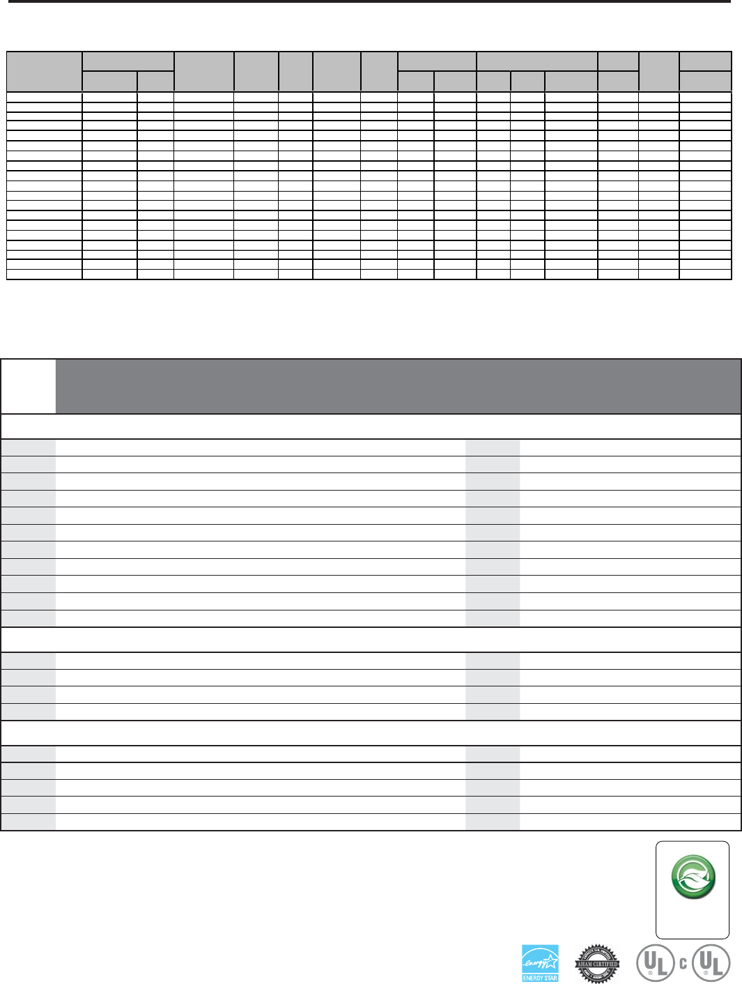
SS08M10 7900 — 115 6.1 677 — — — 11.7 $54 1.0 265 S 99
SS10M10 9500 — 115 7.7 848 — — — 11.2 $68 2.0 260 S 106
SS12M10 12000 — 115 10.0 1071 — — — 11.2 $86 3.0 300 S 112
SS14M10 14000 — 115 12.0 1444 — — — 9.7 $115 3.5 325 S 116
SS12M30 11700/11200 — 230/208 4.8/4.9 1026/982 — — — 11.4/11.4 $82 2.8 275 S 112
SS15M30 14500/14300 — 230/208 6.4/6.8 1405/1385 — — — 10.3/10.3 $112 3.5 360 S 116
SM18M30 17500/17200 — 230/208 7.4/8.0 1635/1617 — — — 10.7/10.7 $131 4.6 350 M 140
SM21M30 20800/20700 — 230/208 9.4/10.3 2080/2070 — — — 10.0/10.0 $166 6.0 425 M 132
SM24M30 23500/23300 — 230/208 11.2/11.9 2500/2479 — — — 9.4/9.4 $200 10.0 390 M 152
SL28M30 27800/27000 — 230/208 13.5/14.4 2865/2812 — — — 9.7/9.6 $229 8.5 600 L 193
SL36M30 36000/35700 — 230/208 19.0/20.5 4235/4200 — — — 8.5/8.5 $338 12.0 725 L 212
Kühl +
Heat Pump
YS10M10* 9500 7500 115 7.8 812 7.6 743 3.0 11.7 $65 1.9 285 S 109
YS12M33 12100/12100 9400/9000 230/208 5.2/5.4 1120/1120 5.6/5.8 1132/1139 2.4 10.8/10.8 $89 3.0 265 S 115
YM18M34 18200/17800 15500/15400 230/208 8.5/8.9 1838/1798 8.5/8.7 1833/1761 2.6 9.9/9.9 $147 5.4 370 M 141
YL24M35 24000/23600 23500/23200 230/208 11.1/12.0 2474/2433 12.2/14.3 2610/2575 2.6 9.7/9.7 † 7.0 600 L 197
Kühl +
Electric Heat
ES12M33 11700/11200 10700/8900 230/208 4.8/4.9 1026/982 16.0/14.7 3500/2900 3.3 11.4/11.4 $82 2.8 275 S 113
ES15M33 14500/14300 10700/8900 230/208 6.4/6.8 1405/1385 16.0/14.7 3500/2900 3.0 10.3/10.3 $112 3.5 360 S 117
EM18M34 17500/17200 13000/10600 230/208 7.4/8.0 1635/1617 19.5/17.0 4200/3500 3.1 10.7/10.7 $131 4.6 350 M 141
EM24M34 23500/23300 13000/10600 230/208 11.2/11.9 2500/2479 19.5/17.0 4200/3500 3.1 9.4/9.4 $200 10.0 390 M 153
EL36M35 36000/35700 17300/14300 230/208 19.0/20.5 4235/4200 24.0/22.4 5500/4650 2.5 8.5/8.5 $338 12.0 725 L 213
PERFORMANCE DATA
SPECIFICATIONS
All models use
environmentally
friendly R-410A
refrigerant.
R-410A
* Operates on 115 volt and is not equipped with supplemental heat. Will not provide heat at temperatures below 40°F.
Friedrich room air conditioners are designed to operate in outdoor temperatures from 60° F to 115° F.
Due to continuing research in new energy-saving technology, specifi cations are subject to change without notice.
As an ENERGY STAR® partner, Friedrich Air Conditioning Co. has determined that the selected ENERGY STAR® () models meet the ENERGY
STAR® guidelines for energy effi ciency.
The consumer- through the AHAM Room Air Conditioner Certifi cation Program- can be certain that the AHAM Certifi cation Seal accurately states
the unit’s cooling and heating capacity rating, the amperes and the energy effi ciency ratio.
Estimated yearly operating cost based on a 2007 national average electricity cost of 10.65 cents per kWh.
† The estimated yearly operating cost of this model was not available at the time the range was published.
*Rating Conditions: 80 degrees F, room air temp. & 50% relative humidity, with 95 degree F, outside air temp & 40% relative humidity, all
systems use R-410A.
SS08M10-A 53 27 115 157 62 12 31 151 400 6.1 32.0 24.0 115 15
YS10M10-A 56 24 114 150 64 12 14 152 395 7.8 7.6 34.5 33.0 115 15
SS10M10-A 52 28 119 150 65 15 28 145 455 8.0 50.0 51.0 115 15
SS12M10-A 50 30 118 163 60 12 23 137 435 10.0 57.0 35.0 115 15
SS14M10-A 49 31 121 170 56 10 22 132 425 12.0 63.0 29.0 115 15
SS12M30-A 49 31 116 158 62 13 21 142 405 4.8 30.0 33.0 230/208v 15
ES12M33-A 51 29 115 158 62 13 18 140 400 4.8 16.0 30.0 33.0 230/208v 15
YS12M33-A 49 31 116 167 65 16 21 140 455 5.2 5.1 26.0 34.5 230/208v15
SS15M30-A 53 27 121 171 62 14 28 138 430 6.4 32.0 32.5 230/208v 15
ES15M33-A 53 27 121 171 62 14 28 138 430 6.4 16.0 32.0 32.5 230/208v 15
SM18M30-A 54 26 122 160 62 9 31 145 450 7.4 42.0 55.0 230/208v 15
EM18M34-A 54 26 122 160 62 9 31 145 450 7.4 19.5 42.0 55.0 230/208v 30
YM18M34-A 50 30 118 168 60 15 24 130 410 8.5 8.5 44.0 49.5 230/208v 15
SM21M30-A 48 32 124 170 55 10 28 137 455 9.4 46.0 55.0 230/208v 15
SM24M30-A 46 34 129 179 55 12 34 123 495 11.0 47.0 40.0 230/208v 20
EM24M34-A 46 34 129 179 55 12 34 123 495 11.0 47.0 40.0 230/208v 30
YL24M34-A 56 24 121 176 62 18 25 135 480 11.1 12.2 47.0 74.0 230/208V 30
SL28M30-A 47 33 126 181 58 12 26 133 430 13.5 60.0 78.5 230/208v 20
SL36M30-A 51 29 129 188 56 12 31 122 470 19.0 96.0 77.0 230/208v 30
BREAKER
FUSE
60 Hertz
Am
p
s
Locked Rotor
Am
p
s
ELECTRICAL RATINGS
Amps
Cool
Voltage
Amps
Heat
R-410A
REF.
Charge in
OZ.
COOLING
PERFORMANCE
DATA*
EVAP. AIR TEMP. DEG.
F
Discharge Air Temp.
Dro
p
F.
Discharge
Temp
OPERATING
PRESSURES
Suction Discharge
Suction
Temp Super Heat Sub-
Cooling
CONDENSER
TEMP DEG. F
8
Installation Information / Sleeve Dimensions
* Minimum extensions when mounted in a window.
** Minimum widths achieved using one side curtain assembly as opposed to both in a standard installation.
NOTE: S,M and L sleeves may be installed in window with no side kits if properly installed.
Circuit Rating/ Breaker
(B)
(C)
Front
SIDE VIEW
Model
Circuit Rating
Breaker or
T-D Fuse
Plug Face
(NEMA#)
Power Cord
Length (ft.)
Wall Outlet
Appearance
SS08M10, SS10M10, SS12M10 and
SS14M10. YS10M10. 125V - 15A 5 - 15P 6
SS12M30, SS15M30, SM18M30 and
SM21M30. 250V - 15A 6 - 15P 4
SM24M30, SL28M30. ES12M33,
ES15M33. YS12M33 250V - 20A 6 - 20P 4
SL36M30. EM18M34, EM24M34,
EL36M35. YM18M34 and YL24M35
250V - 30A 6 - 30P 4
Sleeve Height Width
Depth
with Front
Shell Depth to
Louvers Minimum
Extension
Into Room*
Minimum
Extension
Outside*
Window Width
Thru-the-wall Installation
Finished Hole
Minimum** Maximum Height Width Max. Depth
S15
15/16
"25
15/16
"29" 8 ¾" 5 ¾” 16
15/16
”27
3/8
"42"16
3/16”
26
3/16”
7
3/8
"
M17
15/16
"25
15/16
"29" 8 ¾" 5 ¾”16
15/16
”27
3/8
"42"18
3/16”
26
3/16”
7
3/8
”
L20
3/16"
28" 35 ½” 16 ½" 5
3/8
”18
15/16
”29
7/8
”42"20
3/8
" 28 ¼" 15
1/8
”
Keep the filter clean
Make sure that your air conditioner is always in top performing condition
.ylralugerretlifehtgninaelcyb
Provide good air flow
Make sure the airflow to and from the unit is clear. Your air conditioner puts the
conditioned air out at the top of the unit, and takes in unconditioned air at the
bottom. Airflow is critical to good operation. It is just as important on the outside
.dekcolbtonsiroiretxetinuehtdnuorawolfriaehttahtgnidliubehtfo
Unit placement
If your air conditioner can be placed in a window or wall that is shaded by a tree
rosepardgnisU.yltneiciffeeromneveetarepolliwtinueht,gnidliubre hto naro
blinds on the sunny side of the dwelling will also add to your unit’s efficiency.
Insulation
Good insulation will be a big help in maintaining desirable comfort levels.
Doors should have weather stripping. Be sure to caulk around doors and
windows.
Proper installation of seal gasket
Make sure the seal gasket has been installed properly to minimize noise
and improve effi ciency. If the seal gasket has not been installed, please
refer to the installation instructions.
For the best cooling performance and highest energy efficiency
9
ELECTRICAL DATA
ELECTRIC SHOCK HAZARD
WARNING
Turn off electric power before service or
installation.
All electrical connections and wiring MUST be
installed by a qualifi ed electrician and conform to
the National Electrical Code and all local codes
which have jurisdiction.
Failure to do so can result in personal injury or
death.
Not following the above WARNING could result in fi re or
electically unsafe conditions which could cause moderate
or serious property damage.
Read, understand and follow the above warning.
NOTICE
FIRE HAZARD
Wire Size Use ONLY wiring size recommended for single outlet branch circuit.
Fuse/Circuit Breaker Use ONLY the correct HACR type and size fuse/circuit breaker. Read electrical ratings on unit’s
rating plate. Proper circuit protection is the responsibiity of the homeowner.
Grounding Unit MUST be grounded from branch circuit through service cord to unit, or through separate
ground wire provided on permanently connected units. Be sure that branch circuit or general
purpose outlet is grounded.
Receptacle The fi eld supplied outlet must match plug on service cord and be within reach of service cord.
Do NOT alter the service cord or plug. Do NOT use an extension cord. Refer to the table above
for proper receptacle and fuse type.
The consumer - through the AHAM Room Air Conditioner Certifi cation Program - can
be certain that the AHAM Certifi cation Seal accurately states the unit’s cooling and
heating capacity rating, the amperes and the energy effi ciency ratio.
*HACR: Heating Air Conditioning and Refrigeration
10
Make sure the wiring is adequate for your unit.
If you have fuses, they should be of the time delay type. Before you install
or relocate this unit, be sure that the amperage rating of the circuit breaker
or time delay fuse does not exceed the amp rating listed in Table 1.
DO NOT use an extension cord.
The cord provided will carry the proper amount of electrical power to the
unit; an extension cord may not.
Make sure that the receptacle is compatible with
the air conditioner cord plug provided.
Proper grounding must be maintained at all times. Two prong receptacles
The grounded receptacle should meet all national and local codes and
ordinances. You must use the three prong plug furnished with the air
conditioner. Under no circumstances should you remove the ground
prong from the plug.
Test the power cord
All Friedrich room air conditioners are shipped from the factory with a
Leakage Current Detection Interrupter (LCDI) equipped power cord. The
LCDI device on the end of the cord meets the UL and NEC requirements
for cord connected air conditioners.
To test your power supply cord:
1. Plug power supply cord into a grounded 3 prong outlet.
2. Press RESET (See Figure 1).
3. Press TEST, listen for click; the RESET button trips and pops out.
4. Press and release RESET (Listen for click; RESET button latches
and remains in). The power cord is ready for use.
WARNING: Before Operating Your Unit
MODEL
CIRCUIT RATING
OR TIME DELAY
FUSE
REQUIRED
WALL
RECEPTACLE
AMP VOLT NEMA
NO.
SS08M10, SS10M10,
SS12M10, SS14M10,
YS10M10 15 125 5-15R
SS12M30, SS15M30,
SM18M30, SM21M30 15 250 6-15R
SL25M30, SL28M30,
ES12M33, ES15M33,
YS12M33 20 250 6-20R
SL36M30, EM18M34,
EL25M35, EL36M35,
YM18M34, YL24M35 30 250 6-30R
Table 1.
WARNING
Electrical Shock Hazard
Make sure your electrical receptacle has the
same configuration as your air conditioner’s
plug. If different, consult a Licensed Electrician.
Do not use plug adapters.
Do not use an extension cord.
Do not remove ground prong.
Always plug into a grounded 3 prong oulet.
Failure to follow these instructions can result in
death, fire, or electrical shock.
NOTICE
Do not use the LCDI device as an ON/OFF switch.
Failure to adhere to this precaution may cause
premature equipment malfunction.
Once plugged in, the unit will operate normally without the need to reset
the LCDI device. If the LCDI device fails to trip when tested or if the power
supply cord is damaged, it must be replaced with a new power supply cord
from the manufacturer. Contact our Technical Assistance Line at (800)
541-6645. To expedite service, please have your model number available.
WARNING
15/20A LCDI Device 30A LCDI Device
TEST BEFORE EACH USE
1. PRESS RESET BUTTON
2. PLUG LCDI INTO POWER
RECEPTACLE
3. PRESS TEST BUTTON,
RESET BUTTON SHOULD
POP UP
4. PRESS TEST BUTTON,
FOR USE
DO NOT USE IF ABOVE TEST
FAILS
WHEN GREEN LIGHT IS ON
IT IS WORKING PROPERLY
RESET TEST
WARNING
TEST BEFORE EACH USE
1. PRESS RESET BUTTON
2. PLUG LCDI INTO POWER
RECEPTACLE
3. PRESS TEST BUTTON,
RESET BUTTON SHOULD
POP UP
4. PRESS TEST BUTTON,
FOR USE
DO NOT USE IF ABOVE TEST
FAILS
WHEN GREEN LIGHT IS ON
IT IS WORKING PROPERLY
RESET
TEST
FRR001
Figure 1
11
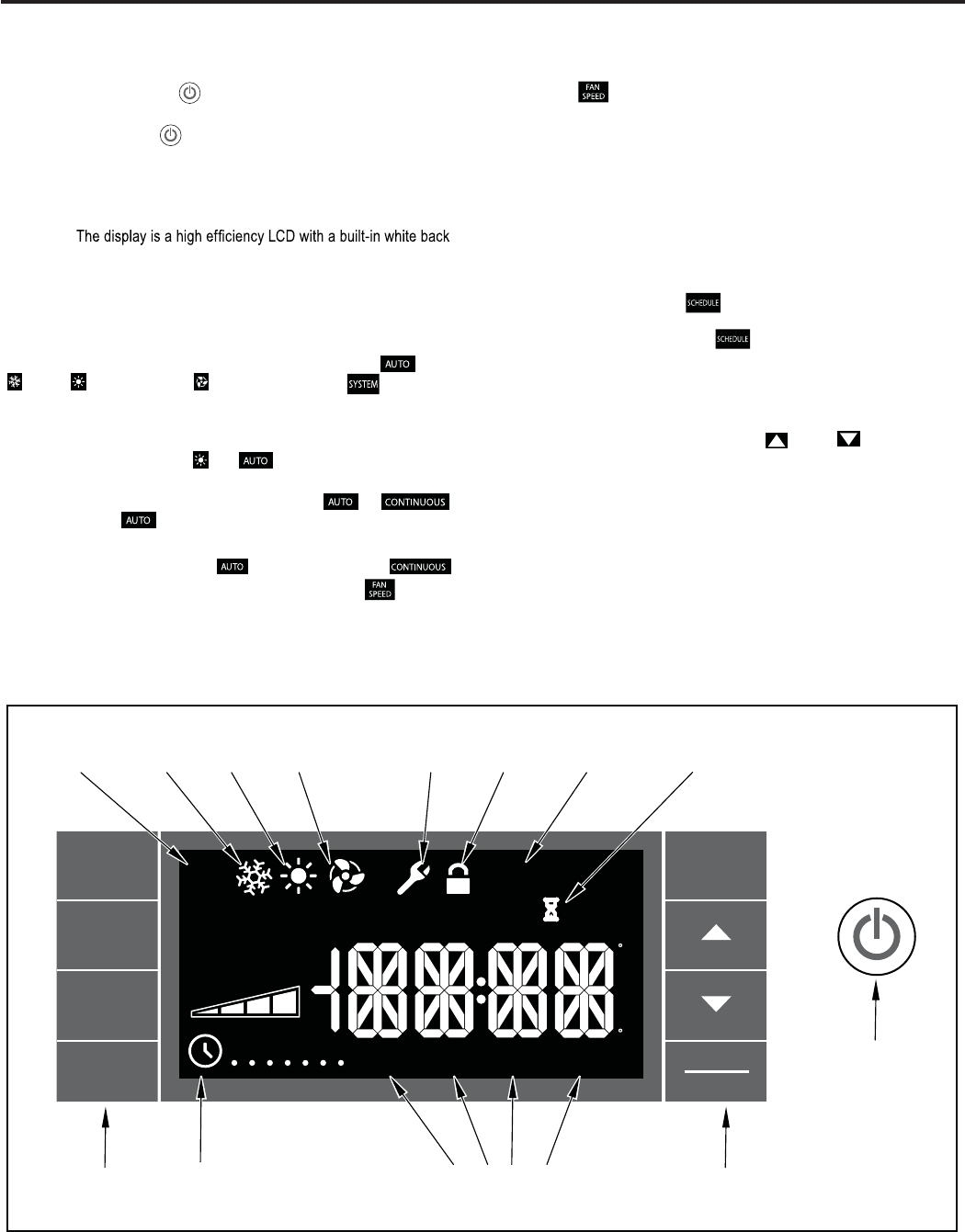
Let’s check out how to control your air conditioner. On the control panel,
just to the left of the POWER , is a liquid crystal display (LCD). All of the
control panel function buttons and mode icons can be viewed in Figure 1.
Power On – Press the button to turn on the air conditioner. The
power button will illuminate to indicate the power is on. The backlight on
the power switch will automatically dim to 20% intensity after
120
seconds
of inactivity. The remote control can also be used to turn power ON / OFF
(See Remote Control).
Display –
light. The back light has an automatic two (2) step dim function.
After 120
seconds of inactivity, the display dims to 20% intensity. After an additional
120 seconds, the display switches off. Touching buttons will automatically
bring the display to full brightness.
There are four control push buttons on each side of the display.
SYSTEM Button – Allows the user to sequentially select, Cool
, HEAT , and FAN ONLY operation. Press the button and
the display advances to the next mode. A new icon appears. At the same
time, the mode displays for two (2) seconds, then returns the display to
th
only units, there are no
e temperature set point for modes other than FAN. Note that on cool
HEAT and modes.
FAN MODE Button – Selects between automatic or
operation. In the mode, the fan only turns on and off when the
compressor operates or the heat function is enabled.
In the SYSTEM FAN ONLY Mode, is not available.
In the
mode, fans speed is determined by your selection on the button.
FAN SPEED Button .sdeeps naf neewteb tceles yllaitneuqes ot desU –
Depending on your model, you can select between LOW, MED, HIGH,
t available on SL and Kuhl+ models.on gnittes xaM .OTUA dna XAM dna
When the button is pressed, the fan speed is temporarily displayed
in the display window, plus a fan speed icon (triangle) changes to indicate
the new speed level. When auto is selected, fan speed automatically varies
depending on the set temperature on the control panel and the actual
room temperature. Let me explain. Say for example you’re working in
your garage and you need to open the big door for several minutes. The
air conditioner will sense a wide difference between the set temperature
and the actual room temperature when this occurs the system fan speed
increases to MAX. The fan speed decreases (in step) as the temperature
difference decreases. When the set point temperature is reached the FAN
speed returns to the original setting.
SCHEDULE Button – The button turns the schedule function on
and off. The current day of the week is indicated as a dot underneath
the day symbol. Pressing the button a second time turns the
schedule function off. The schedule function comes preprogrammed with
recommended energy savings values (Addendum 1). The values may
be changed through the schedule program function (See Programmable
Thermostat).
UP and DOWN arrows – Pressing either (UP) or (DOWN) button
changes the desired room temperature. The factory preset lower and
upper limits are 63° F (16° C) and 99° F (37° C). These buttons are also
used to navigate between function options when using the User Menu or
Maintenance Mode.
BACK Button .detceles neeb sah meti unem a retfa desu si nottub sihT –
It takes the user back to the previous menu level and to save and exit.
DISPLAY/ENTER Button –
Control Panel Operation
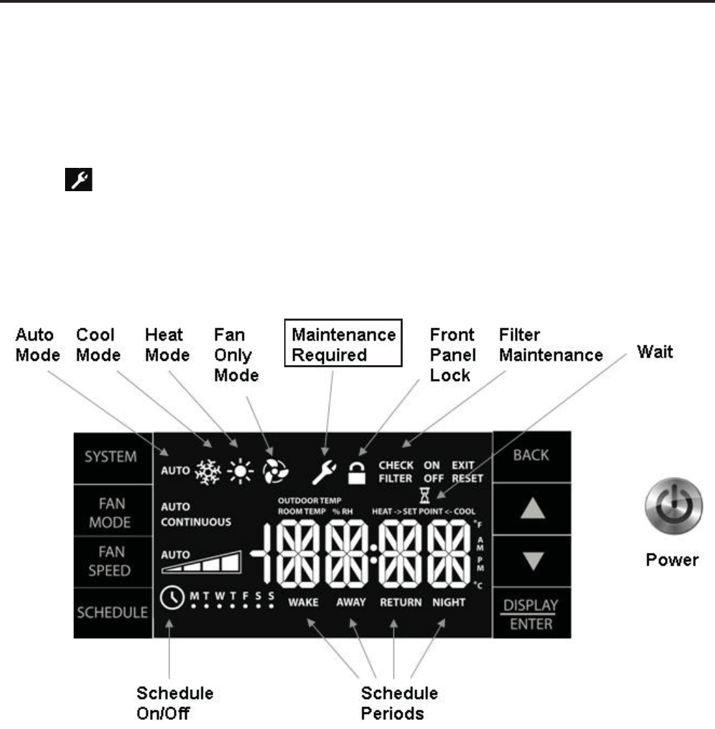
% RH
SYSTEM
FAN
MODE
FAN
SPEED
SCHEDULE
BACK
DISPLAY
ENTER
OUTDOOR TEMP
HE AT -> <- C OOLR OOM TEMP SET POINT
A
P
C
F
AUTO
CONTINUOUS
AUTO CHECK
FI LT ER
ON
OFF
EXIT
AUTO
WAKE AWAY R E T URN NIGHT
MTWTFSS
M
M
RESET
AUTO
MODE
COOL
MODE
SCHEDULE
PERIODS
SCHEDULE
ON/OFF
BUTTONS BUTTONS
POWER
HEAT
MODE
MAINTENANCE
REQUIRED
FAN
ONLY
MODE
FRONT
PANE L
LOCK
FILTER
MAINTENANCE WAIT
This button is used in conjunction with User
Menu and Maintenance Mode operation to select items. This button may
also be used to alternatively display the ROOM TEMPERATURE,
OUTDOOR TEMPERATURE, and TIME. If the display is left inactive for
10 seconds it will reset to the TEMPERATURE SET POINT.
Figure 1
12
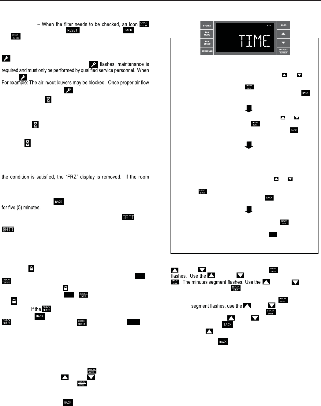
CHECK FILTER
appears on screen. The word “ ” appears next to the .nottub
The alert is issued when the fan run .sruoh 005 naht retaerg si emit
This alert may be reset by the user (Refer to Special Functions, Filter Reset).
Maintenance Required – When maintenance is required, a service icon
appears on screen. This icon will not be dismissed until maintenance
has been performed. If the service icon
the icon .noitidnoc lamronba na desnes sah metsys eht ybdnats no si
is established the service icon goes away.
Wait – The WAIT icon .evitca si tuokcol rosserpmoc eht nehw setanimulli
Whenever the compressor shuts off, system pressures must be allowed
to equalize. At this time, an internal timer begins a count-down from up to
240 seconds. If a demand for heat or cool occurs during this count-down
the WAIT icon displays letting you know that the compressor will not
operate until the count-down has completed. This timer prevents damage
to the unit if it tries to start too quickly after it stops running. Normally the
WAIT icon is off. Once the timer has cleared, the air conditioner will
heat or cool based on the temperature setting. Electric heat is not affected
by this timer.
Protection Alert (Freeze) – If the room freeze protection is active, the
display indicates this by showing Room Freeze Protection "FRZ". Once
temperature is less than 40° F (4° C), and the air conditioner is equipped with
electric heat, the room freeze protection will activate. The air conditioner
will run high fan and electric heat until the room temperature reaches
46° F (8° C). Pressing the button delays the freeze protection function
Low Battery – When the battery is low a warning display will be
inserted before other messages such as “COOL”. If the Low Battery
alert is on, the battery in the control unit must be changed. Refer
to the changing the battery procedure. Once the battery is changed, the
alert message will go off. Refer to Troubleshooting Tips. Under normal
conditions the battery life should be greater than 7 years.
Sp
ALERTS (The control system has five (5) customer alerts)
ecial Functions
Panel Lock – The front panel push buttons can be locked to prevent
inadvertent operation. To lock the front panel, press and hold the SCHEDULE +
buttons for three (3) seconds. A double beep indicates your mode
change was successful and a icon appears on the display. To unlock
the display, press and hold the + .sdnoces )3( eerht rof snottub
The icon will no longer be visible.
Filter Reset –
icon displays, the timer may be reset by pressing
and holding the button for three (3) seconds. A beep indicates the
system timer was reset and the icon and the word " RESE T " will
no longer be visible.
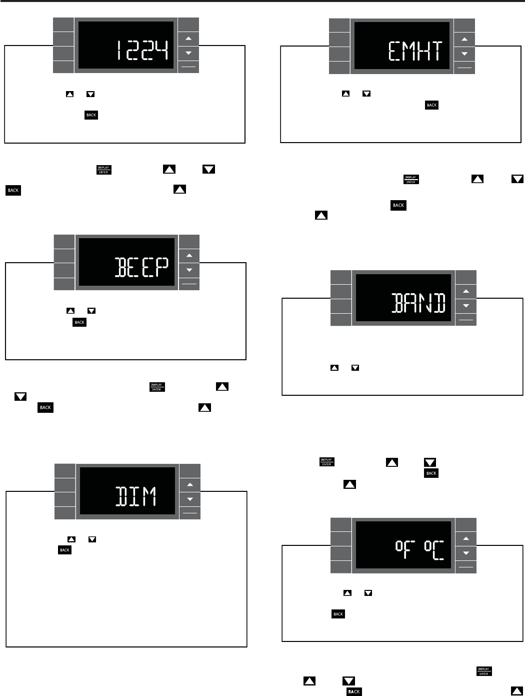
User Menu Functions – The User Menu Functions allows you to change
the following selections: Set TIME, 12/24 Hour Clock Format, BEEP ON /
OFF, DIM ON / OFF, Emergency Heat (EMHT) ON / OFF, Auto BAND Adjust,
F/ C Select, FRZ ON / OFF, Temp Offset (TO) and the Automatic Temperature
To enter the User Menu, press and hold for 3 seconds, the TIME
selection appears. Use the (UP) or (DOWN) buttons to scroll
through the User Menu. Press the button to enter the displayed
function. If left inactive for 15 minutes the User Menu display will no longer
be visible and it returns to normal operation mode display. To manually
exit the User Menu, press the button.
Time Setting – When in the User Menu, on the Control Panel, use the
(UP) and (DOWN) to select TIME. Push , the hours segment
(UP) and hsup neht ,ruoh eht tes ot )NWOD(
(UP) and (DOWN)
to set the minutes, then push .
NOTE: If the AM or PM indicator is incorrect, push until the hours
(UP) or (DOWN) to advance
the hour segment 12 hours, then push . The day of the week
displays. Use the (UP) or (DOWN) to select the current
day. Press the key to
save and go back to the TIME screen.
Press (UP) to go to the next menu 1224.
NOTE: Pressing the button again will exit the user menu function
mode. Or simply leave the control inactive for 15 minutes and
the control will return back to normal operation.
The hour digits flash first. The user presses the or
to change the hours. To change AM-PM, the hours must be
advanced 12 hours. Press the key to change to the
minutes. To exit the selection process, user presses the
key which will go to the time screen.
The minutes digits flash. The user presses the or
to change the minutes. Press the key to change the days.
To exit the selection process, the user presses the key
which will go to the time screen.
The dot underneath the days of the week begins to blink to
indicate which day it is. If the user has not set the date before,
the dot starts on Monday. If the user is making a correction to
previously set information the dot appears under whichever
day the unit thinks it is. The user can press or to move
the dot left or right (respectively) along the week. The user
presses to loop back to the hours setting. To exit the
selection process, the user presses the key which will go
to the time screen.
Tuesday has been selected. The user presses to loop
back to the hours setting. To exit the selection process and
accept the changes, the user presses the key which will go
to the time screen.
BACK
Sensing Feature (ATSF).
SCHEDULE
13
User presses or to toggle between Beep On and Beep
Off. Press the key to accept the change and exit the
selection process.
SYSTEM
FAN
MODE
FAN
SPEED
SCHEDULE
BACK
DISPLAY
ENTER
EXIT
Audible Alerts – You can select to have the control beep when entering
menus. When BEEP is displayed press the key then press (UP)
or (DOWN) to toggle between ON and OFF. To accept the change,
press the key to return to the BEEP screen. Press the (UP) to go
to the next menu EMHT on Kühl+ models or F C for Kühl models.
Clock Type – You may select between a 12 hr and 24 hr clock. When
1224 is displayed press the key then press (UP) or (DOWN)
to toggle between 12 hr and 24 hr clock. To accept the change, press the
key to return to the 1224 screen. Press the (UP) to go to the
next menu BEEP.
User presses or to toggle the format between 12HR and
24HR display. To exit the selection process and accept the
change, press the key.
SYSTEM
FAN
MODE
FAN
SPEED
SCHEDULE
BACK
DISPLAY
ENTER
EXIT
Emergency Heat – The Kühl+ heat pump models (YS, YM, YL) have
a special feature that is designed to keep the unit providing heat.
When EMHT is displayed press the key then press (UP) or
.FFO dna NO neewteb elggot ot )NWOD(
To accept the change, press the .neercs THME eht ot nruter ot yek
Press the (UP) to go to the next menu BAND
In the unlikely event of a compressor failure, the heat pump unit may be
switched to operate in the electric heat mode only until repairs can be
made.
.
User presses or to toggle between Emergency Heat On
and Emergency Heat Off. Press the key to accept the
change and exit the selection process.
SYSTEM
FAN
MODE
FAN
SPEED
SCHEDULE
BACK
DISPLAY
ENTER
EXIT
User presses or to select between AUTO, DM 20, OFF.
Press the key to accept the change and exit the
selection process.
The Dim Auto automatically dims the display to 20% and then
turns it off after a period of time. The Dim 20 setting behavior
is similar to AUTO, but prevents the display from turning off.
Minimum brightness is 20%. The Dim Off setting forces the
display to run at full brightness.
FAN
SPEED
SCHEDULE DISPLAY
ENTER
The menu allows the user to adjust the minimum spread
between the Auto Cool set point and the Auto Heat set point.
Press the or key to adjust. The adjust range is 3 to 10.
SYSTEM
FAN
MODE
FAN
SPEED
SCHEDULE
BACK
DISPLAY
ENTER
EXIT
User presses or at the same time to toggle between
Fahrenheit or Celsius as their temperature unit of choice.
Press the key to accept the change and exit the selection
process.
SYSTEM
FAN
MODE
FAN
SPEED
SCHEDULE
BACK
DISPLAY
ENTER
EXIT
Auto Changeover ‘Dead Band’ – A buffer Zone between heating and
cooling in which no conditioning occurs. For Kühl+ models with the auto
changeover feature you can select the temperature band between heating
and cooling. From the factory the band is set at 3° F (-16° C). The band is
adjustable from 3° F (-16° C) to 10° F (-12° C). When BAND is displayed
press the key then press (UP) or (DOWN) to toggle between
3 and 10. To accept the change, press the key to return to the BAND
screen. Press the (UP) to go to the next menu F C.
Fahrenheit / Celsius Selection – You may select between displaying
temperature in F or C. When F C is displayed press the key then
press (UP) or (DOWN) to toggle between F and C. To accept the
change, press the key to return to the F C screen. Press the
(UP) to go to the next menu FRZ.
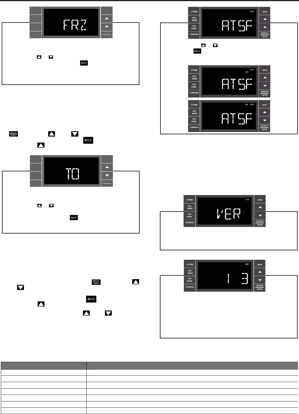
14
Freeze Protection – The Kühl+ models have a special feature that is
designed to keep the interior space above freezing by energizing the
electric heater anytime the indoor room temperature falls to 40° F (4° C) .
With the freeze protection feature turned on, when the unit senses the
indoor temperature fall to 40° F (4° C) the unit will run the heater and high
fan until the space reaches 46° F (8° C) When FRZ is displayed press
the key then press (UP) or (DOWN) to toggle between ON
User presses or to select between Freeze Protection On
& Freeze Protection Off. Press the key to accept the
change and exit the selection process.
SYSTEM
FAN
MODE
FAN
SPEED
SCHEDULE
BACK
DISPLAY
ENTER
EXIT
User presses or to select between ATSF On or Off.
Press the key to accept the change and exit the
selection process.
F
F
Y
R
and OFF. To accept the change, press the key to return to the FRZ
screen. Press the (UP) to go to the next menu TO.
Temperature Offset – In some cases the built in thermostat on the unit
may not display the temperature as it is felt in the room. This can be caused
by many things including the size of the unit, the heat load on the room or
other factors. Friedrich allows you to select the appropriate temperature
offset to make the temperature readout as accurate as possible for your
application. In many cases the factory 0° F (-18° C) offset will provide
an accurate temperature readout. To change the offset follow these
instructions. When TO is displayed press the key then press
(UP) or (DOWN) to toggle between 0° F (-18° C) and 8° F (-13° C) .
In most instances an offset from 0° F (-18° C) to 2° F (-17° C) is all that is
necessary. To accept the change, press the key to return to the TO
screen. Press the (UP) to go to the next menu ATSF.
You may cycle through the menus using the (UP) or (DOWN) keys
User presses or to increment/decrement the temperature
offset (TO) for the room temperature sensor. (Maximum offset
= +/- 8 degrees F). Press the key to accept the change
and exit the selection process
SYSTEM
FAN
MODE
FAN
SPEED
SCHEDULE
BACK
DISPLAY
ENTER
EXIT
Automatic Temperature Sampling Feature - The automatic temperature
sampling feature maintains a balanced temperature throughout the room
by circulating the air for 30 seconds once every 9 minutes that the unit is
For display only. No user selectable options.
F
F
Y
to access any of the menus.
Firmware Version - When VER is displayed press Display /
Enter key. The firmware version is displayed as left digit
(Major) and right digit (Minor). This version number should be
used along with Model and Serial numbers for service.
not running when it is set to cooling or heating mode. By circulating the air
the unit can detect hot or cold areas in the room and operate the unit to
cool or warm the room as necessary. This function is only available when
the fan mode is set to ‘AUTO’ or in COOL or HEAT Mode. (Heating function
only available on Kuhl+ units)
Key Sequence
Action
Filter Reset Press BACK key for 3 sec + play double beep ()
Enter User Menu Press DISPLAY/ENTER key for 3 sec + play double beep ()
Enter Maintenance Menu Press SYSTEM + SCHEDULE + BACK + DISPLAY/ ENTER for 3 sec + play double beep ()
Enter & Exit Schedule Programming Press SCHEDULE for 3 sec + play double beep ()
Reset Error Codes & Error History Press
+
for 3 sec + play double beep ()
Lock Control Panel Press SCHEDULE + DISPLAY/ENTER f
Schedule ON/OFF Press SCHEDULE once each time
or 3 sec + play double beep ()
DIGITAL CONTROL PANEL'S ACCESS CODES SUMMARY
15
Remote Control Operation
Remote Control – Refer to Figures 11 and 12 during operation description.
Getting Started – Install two (2) AAA batteries in the battery compartment
located on the back of the unit.
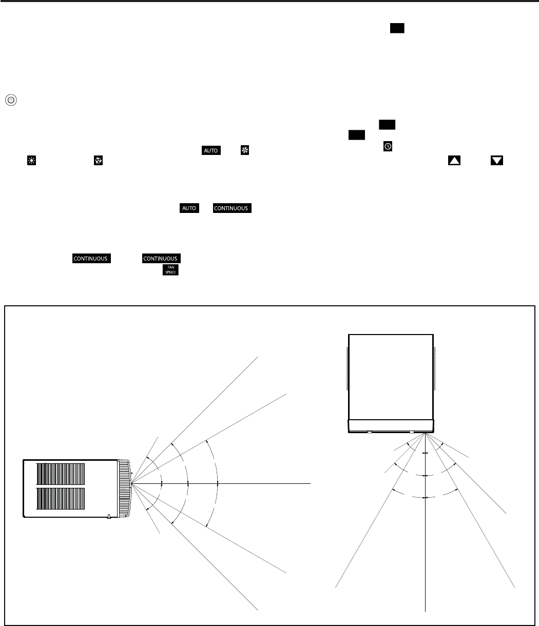
Operation – The remote control should be within 25 feet of the air
conditioner for operation (Refer to Figure 10 for effectiveness). Press the
button to turn the remote on. The remote will automatically power off
after 15 seconds if the buttons are not being pressed. The remote must
be on to control the unit.
POWER Button – Turns remote and unit on and off.
SYSTEM Button – Allows the user to sequentially select, Cool ,
HEAT , and FAN ONLY operation. When the button is pressed, the
.egassem yalpsid a aiv detceles neeb sah edom hcihw setacidni yalpsid
Note that when the heating function is not available, the system will
automatically skip the HEAT and AUTO modes.
FAN MODE Button – Selects between automatic ( ) or
operation. In the AUTO mode, the fan only turns on and off when the
compressor operates or the heat function is enabled.
NOTE: AUTO is not available in the FAN ONLY Mode, the display
indicates . In the mode, fan speed is
determined by your selection on the button.
FAN SPEED Button – Used to sequentially select new fan speed, plus
AUTO operation. When the FA N
SPEED button is pressed, the fan speed is
temporarily displayed in the display window, plus a fan speed icon (triangle)
changes to indicate the new speed level. Fan speed automatically varies
depending on the set temperature on the control panel and the actual
room temperature. Let me explain. Say for example you’re working in
your garage and you need to open the big door for several minutes. Since
there is a big difference between your set temperature and the actual room
temperature the system fan speed increases to MAX. It remains at this
speed until the room temperature matches the set temperature.
SCHEDULE Button – The SCHEDULE button turns the schedule function on and
off. Pressing the SCHEDULE button a second time turns the schedule function
off. Only the schedule icon will be displayed.
UP and DOWN Arrows – Pressing either the (UP) or (DOWN)
button changes the desired room temperature. The factory preset lower
and upper limits are 60° F (16° C) and 99° F (37° C). These buttons are
also used to navigate between function options when using the User Menu
or Maintenance Mode.
Remote Effectiveness
Hand Held Remote – Has an operating range of up to 25 ft. The infrared
remote control signal must have a clear path to transmit the command to
the air conditioning unit. The remote signal has some ability to "bounce"
off of walls and furniture similar to a television remote control. The diagram
below shows the typical operating range of the control in a standard room
with 8 ft high ceilings.
30°
45°
60°
30°
45°
60°
25ft
25ft
8ft
4ft
25ft
16ft
6ft
30°
30°
45°
60°
45°
60°
25ft
25ft
25ft
8ft
25ft
25ft
7.5ft
SIDE VIEW
TOP VIEW
Changing Temperature from F˚ (Fahrenheit) To C˚ (Celsius) or Reverse
Be within 25' of unit with the remote control. Press the SYSTEM and FAN MODE buttons at the same time and hold for 3
seconds. The display will show the temperature in Celcius. Do the same to reverse temperature to F˚ (Fahrenheit).
16
Remote Control Operation (Continued)
FRR005
SYSTEM
TEMPERATURE
UP
SCHEDULE
DISPLAY
FAN MODE
POWER
TEMPERATURE
DOWN
FAN SPEED
FRR006
AUTO
ICON
SYSTEM
MODE
FAN
MODE
FAN
SPEED
SCHEDULE
ICON 2 X 16 SEGMENT
DISPLAY
COOL
ICON
HEAT
ICON
FAN ONLY
ICON
°F / °C
ICONs
Figure 1
Figure 2
17
ELECTRONIC CONTROL SYSTEM MAINTENANCE
Display
Introduction
This section contains information on the maintenance alerts, temperature limiting, diagnostic test and how to access. The electronic
control system has a built in maintenance sub system which works constantly behind the scenes to help identify problems with the air
conditioner or control system. When maintenance is required, a service icon appeasrs on the display screen.
This icon will not be dismissed until maintenance has been performed or the problem cleared.
Note: The wrench icon may be on steady or flash, depending on severity. Maintenance should only be performed by qualified service
personell.
Testing the Display
Press the FAN MODE and FAN SPEED buttons at the same time for 3 seconds. All of the display's icons and functions
should light up. If any of them do not light up, the display should be replaced. When the buttons are released, the display
reverts to the original display.
18
Electronic Control System Maintenance Operation
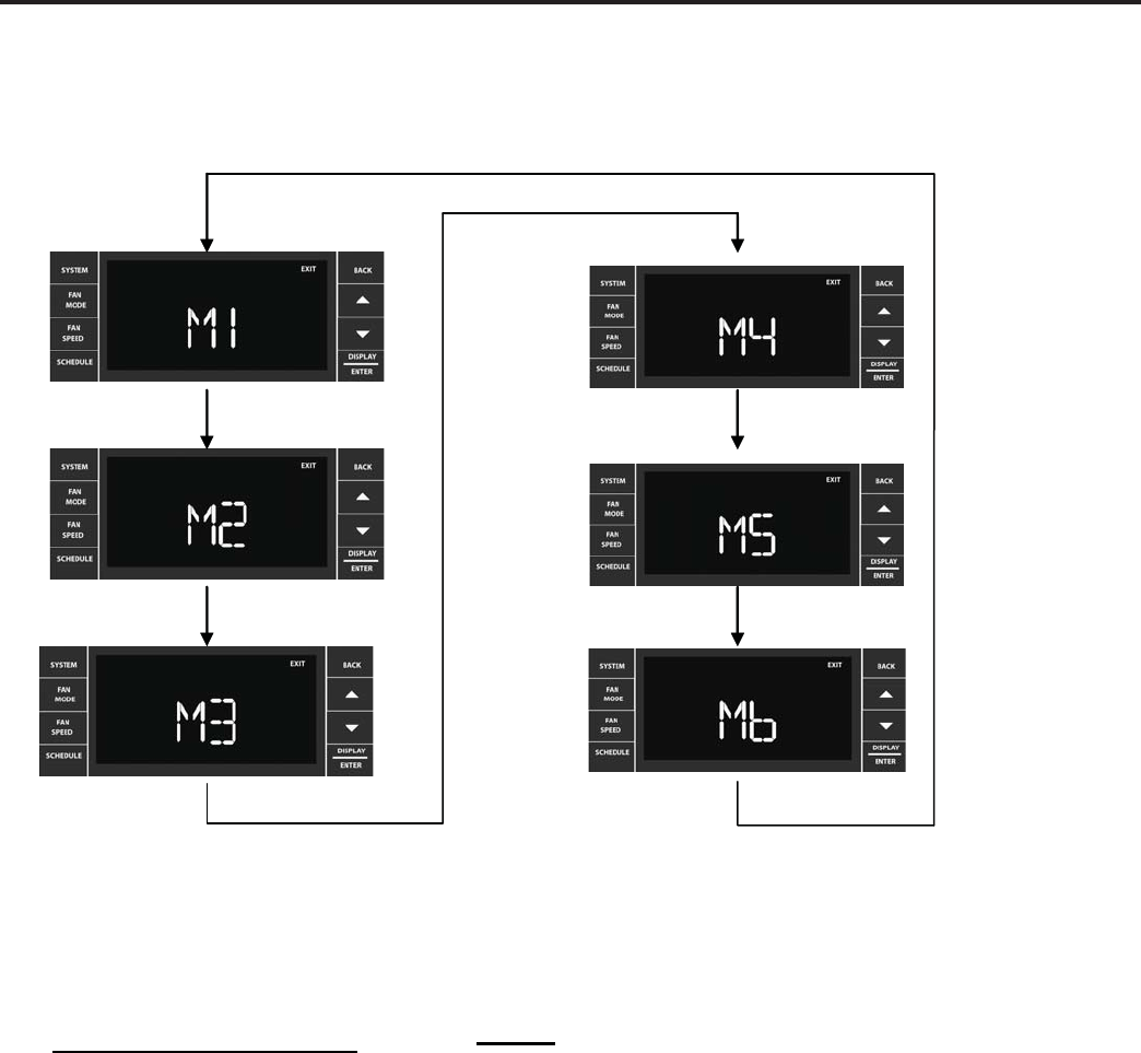
To Enter the Maintenance Section:
Press SYSTEM+SCHEDULE+BACK+DISPLAY/ENTER for 6 seconds.
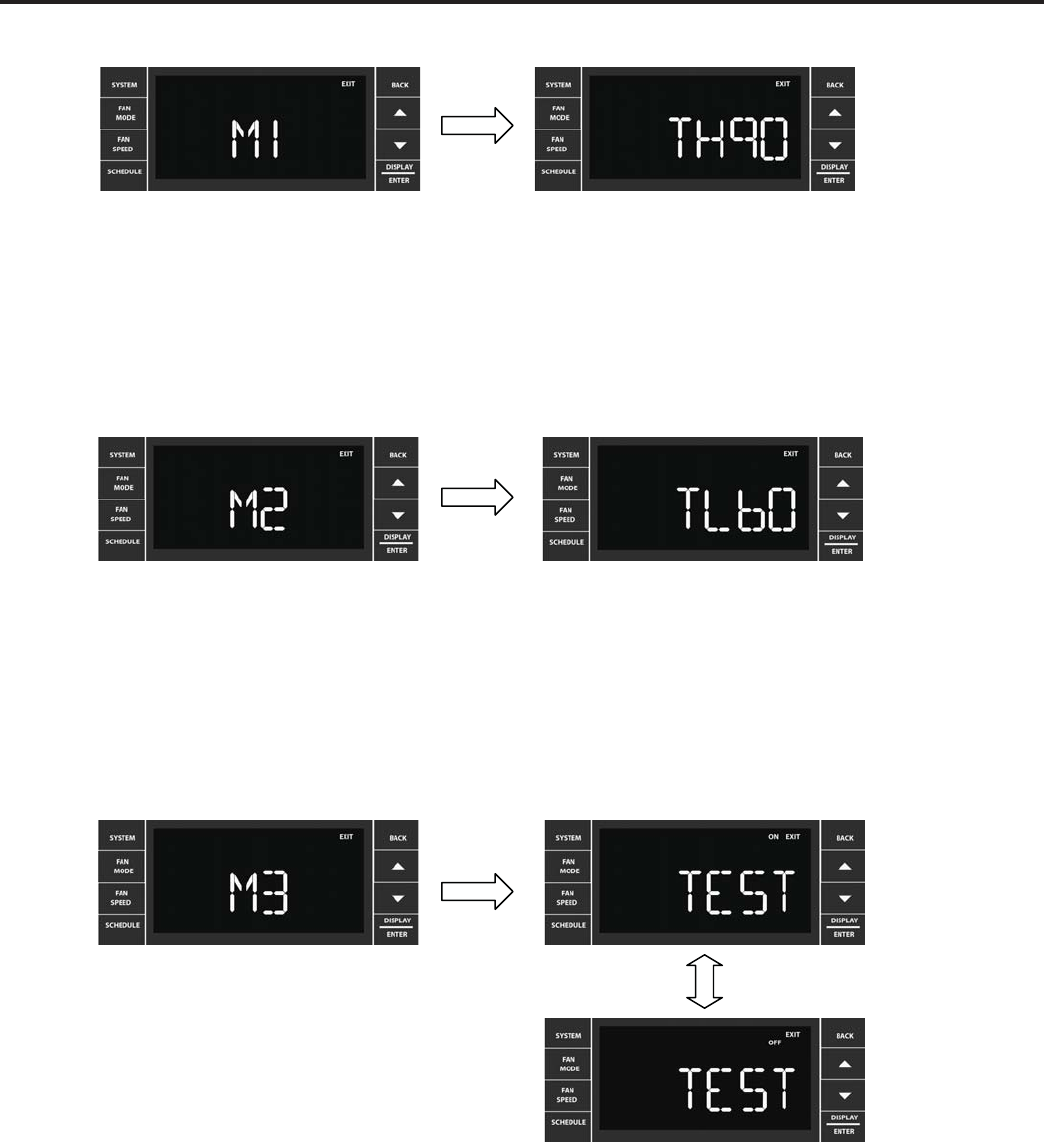
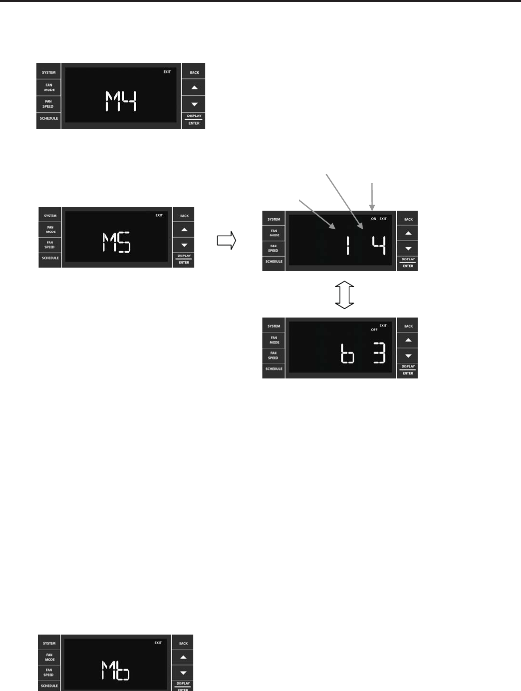
There are 5 maintenance sub-menus M1 through M5.
Maintenance Sub-Menus Access
M1 – Temperature High Limit
Service Only
M2 – Temperature Low Limit
Service Only
M3 – Test Mode Access
Service Only
M4 – Provision Switch Setting & State
Factory Use Only
M5 – Alarms & History
M6 –
Factory Use OnlyFactory Use Only
Service Only
Pressing the ▼or ▲key cycles through the sub-menus. Press DISPLAY/ENTER to
enter a sub-menu. The BACK key is used to exit the menu. Extreme care must
be taken when modifying parameters in the maintenance menus.
19
Temperature High Limit
Temperature Low Limit
M3 – Test Mode Access
Maintenance function 1 is ready to be selected. Press DISPLAY/ENTER to access
the function.
User presses
or
to increment or decrement the upper temperature limit. 99°F
is the maximum upper limit. The current stored high limit is displayed when the
screen is selected. Press the BACK key to accept the value, and exit the sub-menu
to the M1 screen.
Maintenance funtion 2 is ready to be selected. Press DISPLAY/ENTER to access
the fuction
User presses
or
to increment or decrement the lower temperature limit. 60°F is the
minimum lower limit. The current stored lower limit must be displayed when the screen
is selected. Press the BACK key to accept the value, and exit the sub-menu to the M2
screen.
The Following functions Can be Tested
1. System Mode: Cool/Heat Pump Compressor, Electric Heat, Fan Only
2. Fan operation and speeds
Test mode Bypasses:
1. Compressor lock out (time delay)
2. All relay switch’s delays
3. All thermistors delay
4. Automatic heat/cool changeover delay
5. System settings
If M3 switch is left ON it will reset to OFF automatcally after 15 minutes of inactivity.
Maintenance function 3 is ready to be selected. Press
DISPLAY/ENTER to access the function.
User presses the ▼or ▲key to toggle the Test Mode
ON/OFF. Press the BACK key to accept the change
and exit the sub-menu to the M3 screen.
This test selects the system mode of operation directly.
20
M4 – Switch Access (Unit Configuration)
FACTORY USE ONLY
M6 – Factory Use Only
M5 – Error Codes & History
Error Code
Number of Errors Error Code
On/Off
Maintenance funtion 5 is ready to be selected. Press DISPLAY/ENTER to access the function.
The error code display shows the error code number on the left, and the error code
history on the right. User presses the
or
keys to cycle through the error codes.
The current state of the error code is shown with the On/Off icon. To exit the
maintenance sub-menu, press the BACK key to return to the M5 screen.
Shown on this display is error code 1 with 4 occurances. The current state is on.The
error code display shows the error code number on the left, and the error code history
on the right. User presses the
or
keys to cycle through the error codes. The
current state of the error code is shown with the On/Off icon. To exit to the
maintenance sub-menu, press the BACK key to return to the M5 screen. Shown on
this display is error code 6 with 3 occurances. The current state is off.
To Clear Error Codes’ History:
Hold the
or
keys simultaneously for 3 seconds. See page 56 for alarm status and error codes.
21
UNIT OPERATION
There are two basic ways to operate the unit - Front Panel and Wallstat. The Front Panel and Wallstat are never active at the
same time. Switching between these modes is controlled via the (FP) jumper on the Wallstat connector. When the jumper is
ON, the mode = Front Panel.
Front Panel
System Mode Sequence (SCHEDULE = OFF)
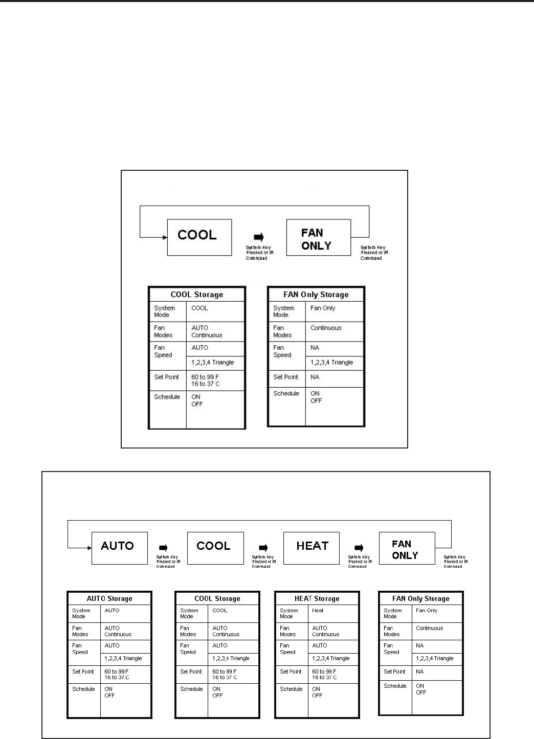
There are two system modes of operation. One for a cool only unit (see figure 1) and one for a heat-cool unit (see figure 2).
System parameters for each system mode are saved when exiting a system mode, and retrieved when entering a new
system mode.
System Mode: Cool Only Units
System Mode: Heat - Cool Units
Figure 1
Figure 2
22
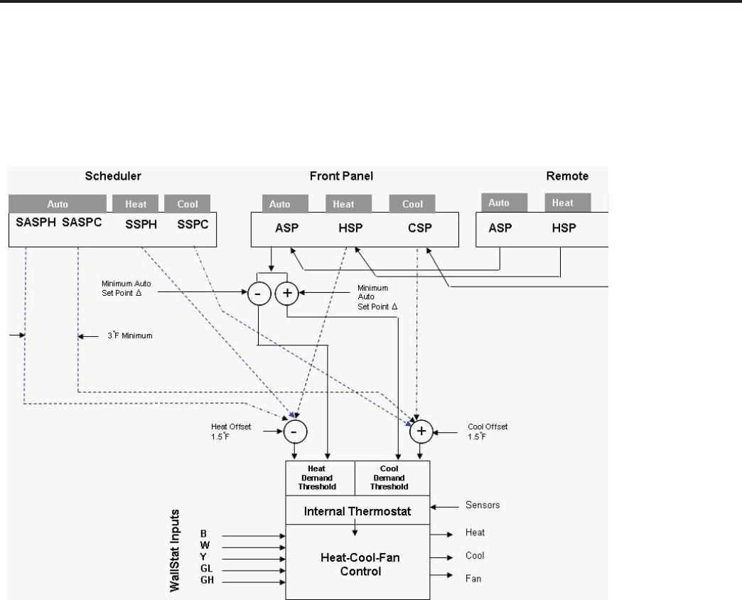
System Set Point Mapping Figure
The air conditioner control system is designed to control different product configurations
with a select set of features. Some models just cool, some cool and heat with electric
heat, and others cool and heat with a heat pump and/or electric heat.
The system set points are mapped to the internal controls as shown below.
There are 8 stored & variable set points in the system:
1 - ASPC: Auto Set Point Cool
2 - ASPH: Auto Set Point Heat
3 - CSP: Cool Only Set Point
4 - HSP: Heat Only Set Point
5 - SASPC: Scheduler Auto Set Point Cool
6 - SASPH: Scheduler Auto Set Point Heat
7 - SSPC: Scheduler Set Point Cool Only
8 - SSPH: Scheduler Set Point Heat Only
Control
Deadband
1.5
1.5
COOL-HEAT SET POINTS
23
ELECTRONIC CONTROL SEQUENCE OF OPERATION
Compressor and Reversing Valve Control
Cooling De-Energized
Energized
On
On
Off
Off
Heat - Heat Pump
Heat - Electric
Fan Only
* The Reversing valve stays in the last state until a call for heat or cooling (see fi gure below)
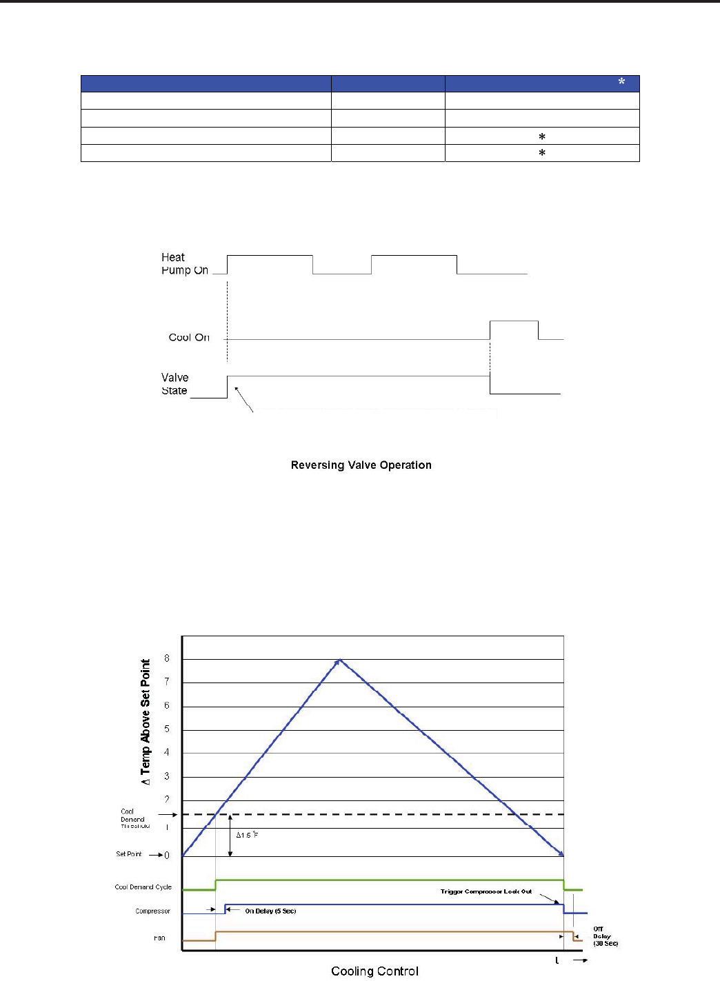
Compressor Operation:
Cooling Mode
Once the ambient temperature rises past the cool demand threshold (Cool Set Point + 1.5 ˚F) (see fi gure below), and
the compressor is not locked out, the cooling cycle begins. As shown in the fi gure below, the fan is started 5 seconds
prior to the compressor. Once the ambient temperature has been lowered to the cool set point (Cool Set Point minus
.25 ˚F), the cooling cycle starts to terminate by shutting off the compressor. After a 30 seconds delay, the fan is shut
off. (See fi gure below for graphic details)
The reversing valve only changes when required
to provide cooling or heat pump. The RV valve
stays in it's last state until required to change.
Active Mode Compressor Reversing Valve State
24
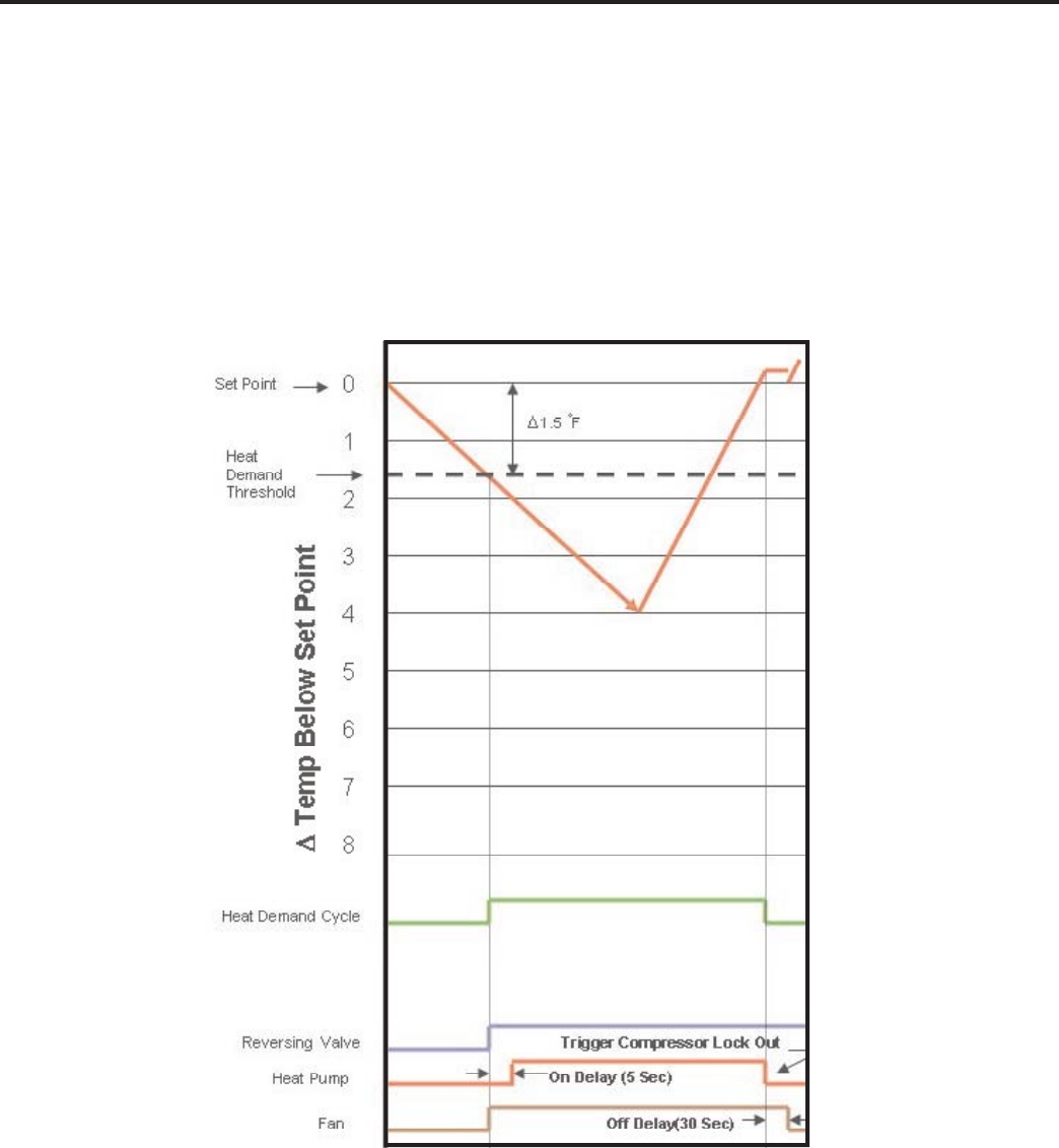
Heat Control (Heat Pump Only)
Heating Mode Control Operation
There are two heating methods: Heat Pump and Electric Resistance Heat.
There are 3 types of units that provide heating: Heat Pump Only (Model YS10M10)
Heat Pump with Electric Heat and Cool with Electric Heat.
Heat Control Operation Heat Pump Only
Once the ambient temperature falls below the Heating Demand Threshold
(1.5 ˚F Below the Heat Set Point Temperature), the heating cycle begins. The fan is turned on 5 seconds later. Once
the ambient temperature has been raised to the Heat Satisfi ed Point (Set point + .25 ˚F), the compressor is turned
off. The fan is turned off 30 seconds later. The fi gure below illustrates the basic heat pump operation.
25
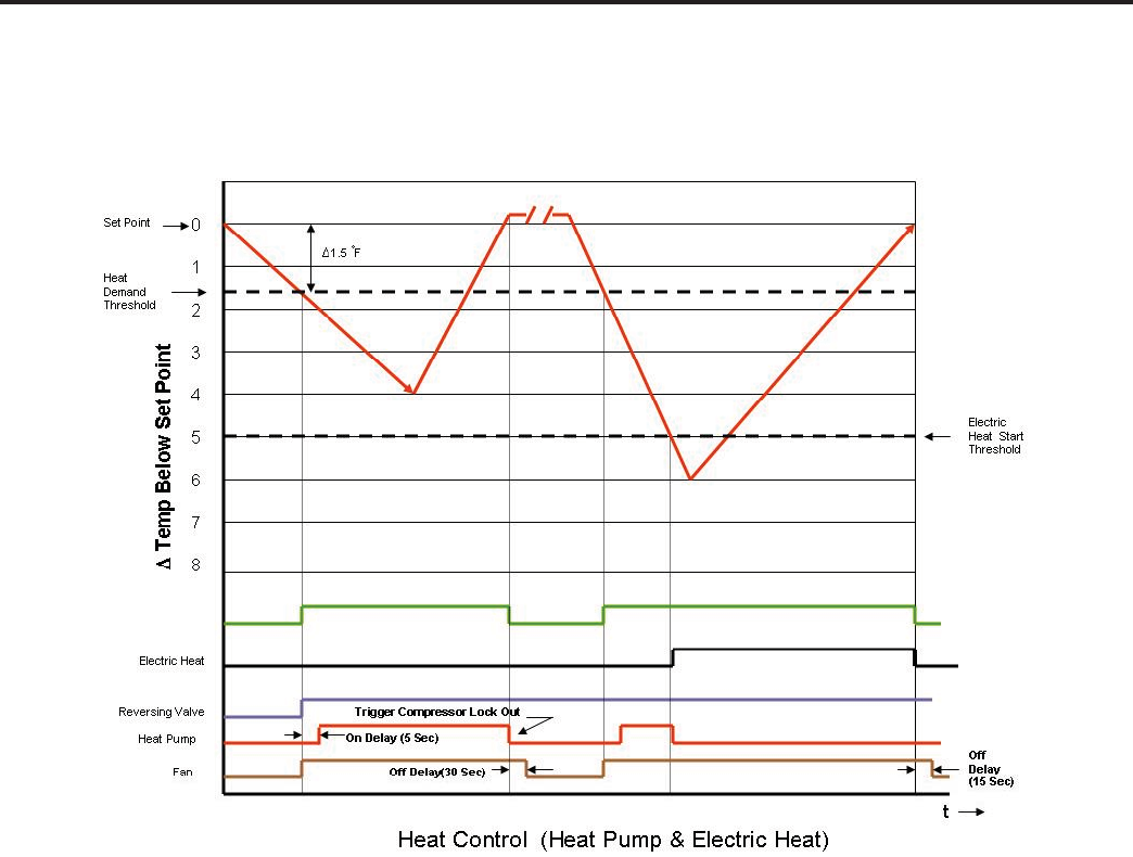
This heating is more complex due to the possibility of two heating methods. If the ambient indoor temperature is be-
low the heat demand threshold (1.5˚F below the heat set point temperature), and the compressor is not locked out,
turn on compressor. If the ambient indoor temperature is 0.25˚F above the heat set point turn off the compressor.
If the compressor is locked out & electric heat is available:
1. Turn on the electric heat until the compressor is not locked out.
2. After lockout, turn off the electric heat, wait 5 seconds, then turn on the compressor.
If Electric Heat is Available
After the Heat button is initially pressed, the unit will run the electric heater until the initial set point is satisfi ed (Hot Start
Feature). After the initial start, the unit will switch to Heat Pump heat and decide between Heat Pump heat and Electric
heat based on the following two monitored conditions:
Condition 1
If the outdoor coil temperature sensor drops to 30 ˚F or less for 2 consecutive minutes, the unit will switch to electric heat
if available. Thereafter, the unit will switch back to Heat Pump heat if the outdoor coil temperature sensor rises to 45 ˚F or
greater.
If Electric Heat is not available (out of order) and the outdoor coil temperature sensor drops to 30 ˚F or less for 2
consecutive minutes, then the compressor and fan will turn off. Thereafter, the unit will switch back to Heat Pump heat if
the outdoor coil temperature rises to 45 ˚F or greater.
Heat Pump With Electric Heat Operation

26
Condition 2
If the Δ (delta) (set point temperature minus the ambient indoor temperature) is greater than 5 ˚F, then the unit will switch
to electric heat, if available. The unit will continue to operate with electric heat until the heat demand is satisfi ed. Note that
the electric heat switches on after the Δ temp passes 5°F and the heat pump switches off. Also note that the electric heat
will run until the heat demand is satisfi ed. When another heat demand cycle is initiated, the heat pump will run unless the
Δ temp is greater than the electric heat threshold.
Emergency Heat
If a compressor fails in the heating season, the Emergency Heat allows the user to override the Heat Pump and heat with
electric heat only. This is controlled via the user interface (See the User Menu Functions page 12).
Note that if heat is the fi rst demand cycle (demand cycle = call for heat or call for cooling) after power restoration, the
control system will run electric heat for the entire cycle if the unit is equipped with electric heat.
Electric Heat Operation in Cool with Electric Heat Units
When in the Heat mode, with and without Fan Mode Auto (Fan cycling):
If the indoor ambient temperature is below the Heat Demand Threshold (Heat Set Point minus 1.5 ˚F), turn on electric
heat. If Ambient is 0.3 ˚F above the Heat Set Point turn off the electric heat.
System Mode Auto
This mode provides automatic change over between cool and heat. The auto mode runs based on the room ambient
temperature vs. the Demand Thresholds. It is only available in Heat-Cool Unit.
Notes:
The Heat Demand Threshold and the Cool Demand Threshold values are derived from the Auto Set Point in the Auto
Mode (refer to page 22). There is a buffer zone as shown in fi gure , where no heating or cooling is allowed to occur. It is
critical that the Cool Demand Threshold be greater than the Heat Demand Threshold by a minimum of 3° while in the Auto
System Mode. For example, if a user enters a value for the Auto Cooling Set Point that violates the minimum Δ 3° rule, the
Auto Heating Set Point will adjust accordingly. This buffer zone (BAND) can be manually adjusted from 3 to 10° (see the
BAND section page 13).
When programming the schedule, the user has the fl exibility to enter the schedule automatic set point cooling (SASPC)
and the schedule automatic set point heating (SSPH) set points directly. These values are monitored to ensure that they
do not violate the minimum 3° Δ rule. If a violation is detected, the opposite set point will adjust to compensate. The
individual heating and cooling rules apply to the auto mode.
Automatic Change Over Delay (Cool with Heat Units)
The change over delay ensures that any system heating or cooling over shoot does not trigger an opposite demand cycle.
The change over delay = 15 min. This timer blocks the opposite demand cycle from running until the timer expires. As an
example, if the last demand was a cool cycle, and another cool cycle is requested, the timer will not block the request.
However, if the last demand cycle was a cool cycle, and heat cycle is requested, the timer will block the request until the
change over delay is expired.
Heat Pump With Electric Heat Operation (Continued)
27
Compressor Lock Out Time
The lockout feature ensures that the compressor is de-energized for a period of time. The timer varies randomly
from 180 to 240 seconds
The compressor lockout is initiated every time the compressor is “off” due to:
(1) Satisfying the temperature set point
(2) Changing mode to fan only or heat
(3) Turning the unit off
(4) Control is fi rst plugged in or power is restored after failure
(5) Line power is restored from a brown out condition
Wait ICON (Hour Glass)
The wait icon will be turned on when the compressor is locked out and during demand for cooling or heat pump
compressor operation. The Wait ICON will be turned off when the condition clears.
Cooling Fan Delay
Fan cycle/Auto mode only
When unit cycles cooling ON – starts the fan 5 seconds EARLY. When unit cycles cooling OFF – DELAYS the fan
off for 30 seconds
Note: this fan delay is disabled during Test Mode
Heating Fan Delay
This is only for fan Mode Auto (Fan cycles with cool/heat operation) and not for continuous fan mode. When unit
cycles Heating ON – starts the fan 5 seconds EARLY. When unit cycles Heating OFF – DELAYS the fan off for 15
seconds
Note: the fan delay is disabled during Test Mode
Fan Speed Change Delay
Relay activation is delayed by a minimum number of seconds. The default for this value is 2 seconds and is used to
eliminate relay chatter.
Fan Only System Mode
The fan is turned on and runs at the specifi ed manually set speed.
Only the Fan is turned on. Cool or Heat operation are off.
(This is different than FAN MODE CONTINUOUS where the fan is on with the cool or heat operation).
Fan Only Rules
1. If the SYSTEM FAN ONLY MODE is selected, the Auto fan mode is disabled, and the fan mode is forced to
continuous. In addition, the auto fan speed is disabled. If the user presses the fan speed key, the menu will skip over
the auto selection. The set point temperature display is off.
2. Any fan speed may be manually selected during Fan Only Mode.
28
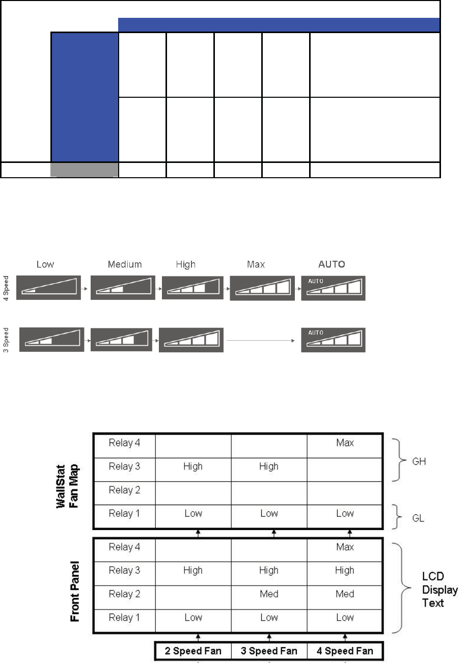
Fan Operation (Front Panel Mode)
Heat – Cool – Auto – Fan Only
Models starting with SS, SM have 4 speeds. Models with SL, and all Kuhl+ have 3 speeds
Note that in the AUTO mode, the speed of the fan will be shown by illuminating the number of bars in the speed triangle.
Speed Selection
1 2 3 4 AUTO
Continuous
"On" " On" "On" " On"
AUTO Operation, but never
turns Off. Uses cool set point
or heat set point vs. ambient
temperature. When there is
no demand, operate at the
lowest available speed.
Fan
AUTO
Turns
On or
Off with
heat or
cool
demand
Turns
On or
Off with
heat or
cool
demand
Turns
On or
Off with
heat or
cool
demand
Turns
On or
Off with
heat or
cool
demand
AUTO operation turns On or
Off with heat or cool demand
Uses cool set point or heat
set point vs. ambient
temperature
Mode
Fan Only "On" " On" "On" " On" Disabled
Table
Fan ICON Detail
The system may have a 3 or 4 speed fan. The Fan Speed ICON will Display as per the table below.
Fan Mapping

29
UNIT OPERATION WITH A WALL-STAT
Front Panel Display Operation in Wall-Stat Mode
The indoor ambient temperature sensor is disabled. All buttons are disabled with the following exception:
A. Maintenance commands.
B. The user menu for Freeze protection (Display/Enter button for Kuhl+ only units).
C. First Button push to illuminate the back light (display will dim).
Maintenance features are operational. This includes the Check Filter, Lock Panel, M3, M4, M5, and the Service
wrench icon. Under T-stat operation, as a default, the selected operating Mode (Cool, Heat or Fan) will not show on
the front panel. The Service ICON ( ) is displayed if a malfunction is detected.
Cool/Heat/Fan modes and Fan speed operations are controlled by the remote wall thermostat.
The fan speeds can be Low or Max for 4 speed units and Low or High for 3 speed units. (T-stat selected must have
2 speed capabilities)
Thermostat terminals requirements:
Must be single stage heat/cool.
For cooling only units: C, R, G, Y.
For cooling with electric heat units: C, R, G, Y, W.
For heat pump units: C, R, G, Y, W, B.
(See page 68 for RT5 T-Stat wiring diagrams)
During Heat Mode:
The B terminal must be continuously energized. The W terminal from the T-Stat must have 24 V AC output to call
for heat. The control board decides on whether to turn on the Heat Pump Heat (compressor) or Electric Resistance
Heat. The Y terminal should not have 24 VAC output during Heat Mode.
30
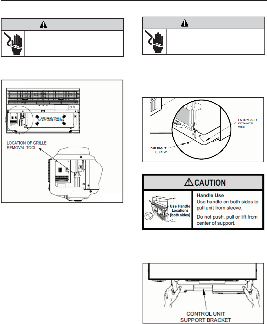
Remove the decorative front cover by using the tool
provided (see fi gure below).
Tighten the four (4) captive screws as indicated by the
arrows in the fi gure above before closing the front panel
(do not over tighten). Ensure the fi lter is in place.
Make sure curtains do not block the side air intake
Notes on reattaching the decorative front cover:
Align the cord notch over the cord and center the fresh
air lever. Align the cover over the User Interface
(UI) to ensure it is clear around it and it does not
depress any buttons. If not installed correctly the
wrench alert symbol could fl ash.
Remove the decorative front cover. (See fi gure at
left). Remove the chassis Entrygard Retainer Wire by
removing the screw at the front right bottom corner screw
(See Figure below). Save this screw for reattachment
after reinstalling the chassis.
Hold the cabinet stationary then use the hand grips on
both ends of the control unit support bracket to pull the
chassis out of the cabinet (see below).
Before reinserting the chassis into the sleeve ensure to
properly reinstall the chassis seal gasket.
REMOVING THE FRONT COVER REMOVING THE CHASSIS
ELECTRIC SHOCK HAZARD
WARNING
Disconnect power to the unit before
servicing. Failure to follow this warning
could result in serious injury or death.
ELECTRIC SHOCK HAZARD
WARNING
Disconnect power to the unit before
servicing. Failure to follow this warning
could result in serious injury or death.
31
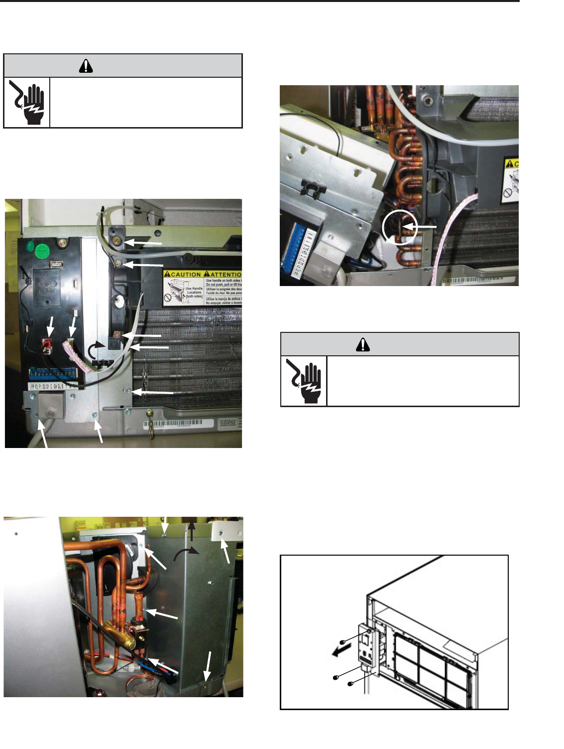
REPLACING THE INDOOR COIL
THERMISTOR
REPLACING THE CONTROL BOARD
ELECTRIC SHOCK HAZARD
WARNING
Disconnect power to the unit before
servicing. Failure to follow this warning
could result in serious injury or death.
Remove the decorative front cover (see page 30).
Remove all indicated screws below (8 total, see fi gure
below). Remove the Discharge Sensor and the User
Interface plugs from the control board.
Remove the decorative front cover (see page 30).
Disconnect discharge sensor plug (red)
Disconnect the User Interface plug (white)
Remove the 3 screws indicated below.
Pull control board and mount plate out and disconnect
the following connectors from it:
Power, capacitor, thermistors, fan, reversing valve
and heater.
Remove the hex screw holding the control board to
its mount plate. Pull out the control board (see fi gure
below).
Replace the indoor coil sensor. Ensure to properly clip
and insulate it at the same location (see fi gure below).
Remove the screws indicated at the side and back plate
(6 total, see fi gure below). Partially lift the top cover and
at the same time carefully swing out from the top, the
back and side plate.
ELECTRIC SHOCK HAZARD
WARNING
Disconnect power to the unit before
servicing. Failure to follow this warning
could result in serious injury or death.
Swing
Out
Up
31
32
ELECTRIC SHOCK HAZARD
WARNING
Disconnect power to the unit before
servicing. Failure to follow this warning
could result in serious injury or death.
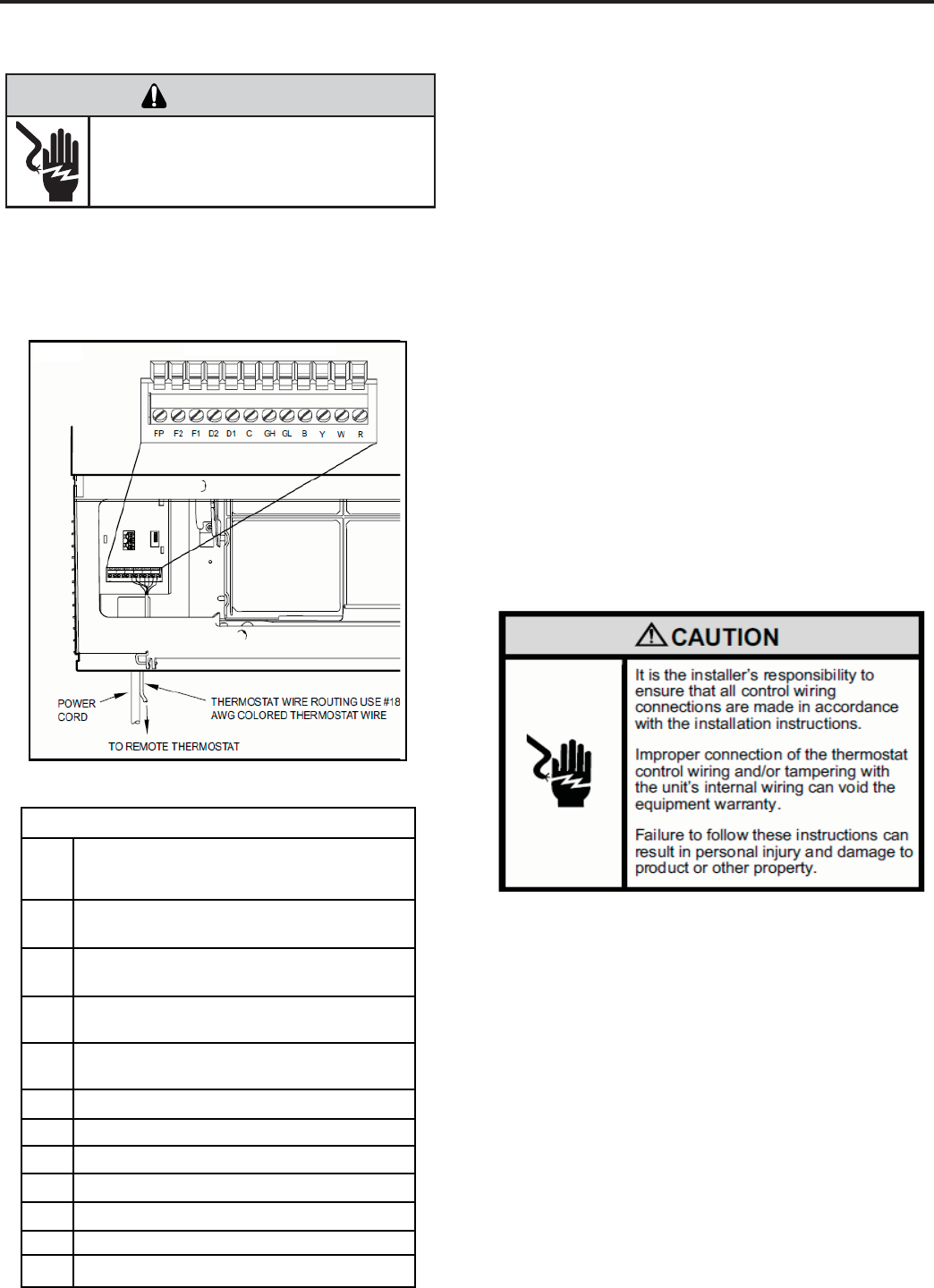
Low Voltage Interface Connector
All Kuhl and Kuhl + units have a low voltage interface connector through
which a Remote Wall Thermostat, Desk Control and Auxiliary Fan’s Relay
can be connected. The interface connector is located on the left side behind
the decorative front cover.
Interface Connector Definitions
Interface Connector Location
Table 1
FP
F2
F1
D2
D1
C
GH
GL
B
Y
W
R
Front Panel. Wire jumper between FP and
F2 enables front panel operation. Jumper off
enables remote wall t-stat operation.
Used with F1 to provide 24 VAC to external
fan relay. (See above for use with FP)
Used with F2 to provide 24 VAC to
external fan relay.
Used with D1 for desk control on or off
operation.
Used with D2 for desk control on or off
operation.
Common Ground Terminal
Call for high fan
Call for low fan
Call for compressor
Call for heating
24V Power from Electronic Control to Wall
Call for heat pump reversing valve
Figure 1
Adding a Remote Wall Thermostat
An external thermostat may be added to the air conditioner to provide
remote temperature sensing and control.
Thermostat Selection
Friedrich recommends the use of either the Friedrich RT4 or RT5. These
thermostats are single stage heat/cool, manual changeover. The RT4 is a
digital display thermostat with single speed fan control. The RT5 features
a digital display, two fan speed selection, fi lter check light, temperature
limiting, status indicator light, room temperature offset, backlight and
battery backup. Other thermostats may be used as long as they are single
stage heat/cool and are confi gured correctly for the unit.
Thermostat terminals requirements:
For cooling only units: C, R, G, Y.
For cooling with electric heat units: C, R, G, Y, W.
For heat pump units: C, R, G, Y, W, B.
For two fan speeds, thermostat must have 2 fan speed selection.
During Heat Pump Mode:
The B terminal must be continuously energized. The W terminal must have
24 VAC output to call for heat. The control board decides on whether to
turn on the Heat Pump Heat (compressor) or Electric Heat. The Y terminal
should not have 24 VAC output during heat mode.
To enable the remote thermostat operation, remove the jumper between
terminals FP & F2 on the interface connector. Connect the thermostat
using Figure 1 and Table 1 as a guide.
Procedure
1) Unplug the unit.
2) Unscrew and remove the decorative front cover. (Page 30)
3) Locate the Interface Connector (24 VAC terminal strip (See fi gure 1 at
left) and remove the jumper wire at FP and F2.
4) Make the wire connections according to the confi guration needed for
your unit (see above or page 68 for wiring diagrams).
5) Once each wire is matched and connected, the unit is now ready to be
controlled by the thermostat.
6) Reattach the decorative front cover (see page 30).
Note: Under T-Stat operation the front panel is disabled
except the Maintenance functions (see page 29 for details).
Connecting a Remote Wall
Thermostat
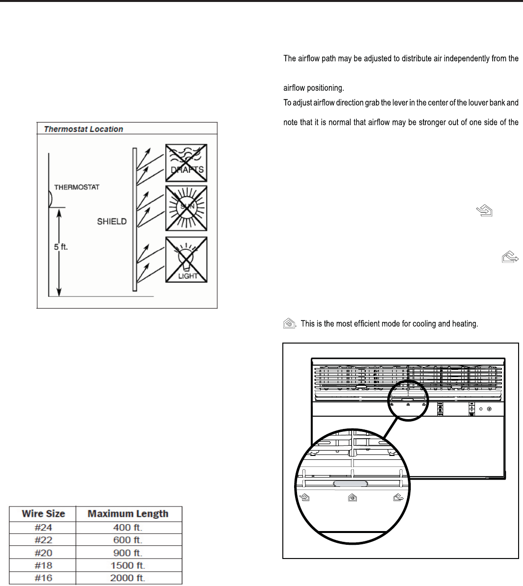
33
Remote Wall Thermostat Location
The thermostat should not be mounted where it may be affected by drafts,
discharge air from registers (hot or cold), or heat radiated from the sun
appliances, windows etc.. The thermostat should be located about 5 Ft.
above the fl oor in an area of average temperature, with good air circulation.
Mercury bulb type thermostats MUST be level to control temperature
accurately to the desired set-point. Electronic digital type thermostats
should be level for aesthetics.
Note: An improperly operating or poorly located remote wall thermostat
can be the source of perceived equipment problems. A careful check of the
thermostat’s location and wiring must be made then to ensure that it is not
the source of problems.
Desk Control
The unit’s electronic control has built-in provisions for connection to an
external switch to control power to the unit. The switch can be a central
desk control system or even a normally open door switch.
For desk control operation, connect one side of the switch to the D1
terminal and the other to the D2 terminal (See page 32). Whenever the
switch closes, the unit operation will stop.
Maximum Wire Length for Desk Control Switch
Auxiliary Fan Control
The electronic control also has the ability to control a 24 VAC relay to
activate an auxiliary, or transfer fan. The outputs are listed as F1 and F2 on
the interface connector (See page 32).
To connect the relay, simply wire one side of the relay to F1 and the other
side to F2. Anytime that the fan runs, the terminals will send a 24 VAC
signal to the relay. The relay must be 24 VAC, 50mA or less.
Note: The Desk Control, Auxiliary Fan relay and wires must be fi eld supplied.
Airflow Selection and Adjustment
Air flow direction adjustment
left or right side of the discharge opening. Each of the banks of louvers
can be directed left, right, up or down in order to achieve the most optimum
move it in the direction that you would like the air to be directed. Please
louvers than the other.
TO BRING IN FRESH AIR – Move the lever to the Fresh Air position
which allows outside air to enter the room. This is useful in fall and spring as
a means of bringing in fresh outside air when using FAN ONLY . It can also
be used in the summer with the compressor in the Cooling Mode if you wish.
Fresh air and exhaust control
Your air conditioner has the ability to bring fresh air into the room or exhaust
stale air out of the room. The control slide is found on the upper part of
the unit (See Figure).
TO EXHAUST INDOOR AIR – Move the lever to the Exhaust
position. This will allow stale air to be expelled to the outside of the dwelling.
This is especially handy in the spring or fall when indoor air tends to get
stale, or after a social gathering involving smokers, or to remove cooking
odors.
BEST PERFORMANCE – Move the lever to the Re-Circulate Position
FRR008
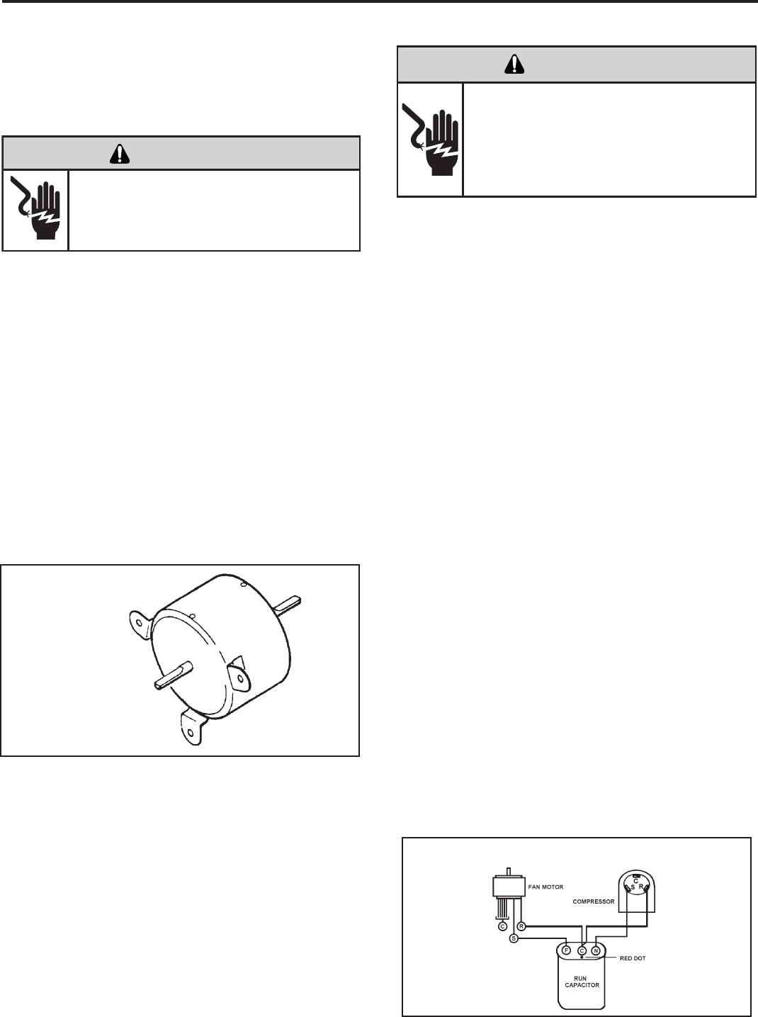
34
CAPACITORS
ELECTRIC SHOCK HAZARD
WARNING
Turn off electric power before servicing.
Discharge capacitor with a 20,000 Ohm 2 Watt
resistor before handling.
Failure to do so may result in personal injury,
or death.
Many motor capacitors are internally fused. Shorting the
terminals will blow the fuse, ruining the capacitor. A 20,000
ohm 2 watt resistor can be used to discharge capacitors
safely. Remove wires from capacitor and place resistor
across terminals. When checking a dual capacitor with
a capacitor analyzer or ohmmeter, both sides must be
tested.
Capacitor Check with Capacitor Analyzer
The capacitor analyzer will show whether the capacitor is
“open” or “shorted.” It will tell whether the capacitor is within
its micro farads rating and it will show whether the capacitor
is operating at the proper power-factor percentage. The
instrument will automatically discharge the capacitor when
the test switch is released.
Capacitor Connections
The starting winding of a motor can be damaged by a
shorted and grounded running capacitor. This damage
usually can be avoided by proper connection of the running
capacitor terminals.
From the supply line on a typical 230 volt circuit, a 115 volt
potential exists from the “R” terminal to ground through a
possible short in the capacitor. However, from the “S” or
start terminal, a much higher potential, possibly as high as
400 volts, exists because of the counter EMF generated
in the start winding. Therefore, the possibility of capacitor
failure is much greater when the identifi ed terminal is
connected to the “S” or start terminal. The identifi ed
terminal should always be connected to the supply line, or
“R” terminal, never to the “S” terminal.
When connected properly, a shorted or grounded running
capacitor will result in a direct short to ground from the “R”
terminal and will blow the line fuse. The motor protector
will protect the main winding from excessive temperature.
Dual Rated Run Capacitor Hook-up
BLOWER/FAN MOTOR - TEST
1. Determine that capacitor is serviceable.
2. Disconnect fan motor wires from fan speed switch or
system switch.
3. Apply “live” test cord probes on black wire and common
terminal of capacitor. Motor should run at high speed.
4. Apply “live” test cord probes on red wire and common
terminal of capacitor. Motor should run at low speed.
5. Apply “live” test cord probes on each of the remaining
wires from the speed switch or system switch to test
intermediate speeds. If the control is in the “MoneySaver”
mode and the thermostat calls for cooling, the fan will
start - then stop after approximately 2 minutes; then the
fan and compressor will start together approximately 2
minutes later.
Figure 23
Blower/Fan Motor
FAN MOTOR
A single phase permanent split capacitor motor is used to drive
the evaporator blower and condenser fan. A self-resetting
overload is located inside the motor to protect against high
temperature and high amperage conditions. (See Figure 23)
ELECTRIC SHOCK HAZARD
WARNING
Disconnect power to the unit before
servicing. Failure to follow this warning
could result in serious injury or death.
COMPONENTS TESTING
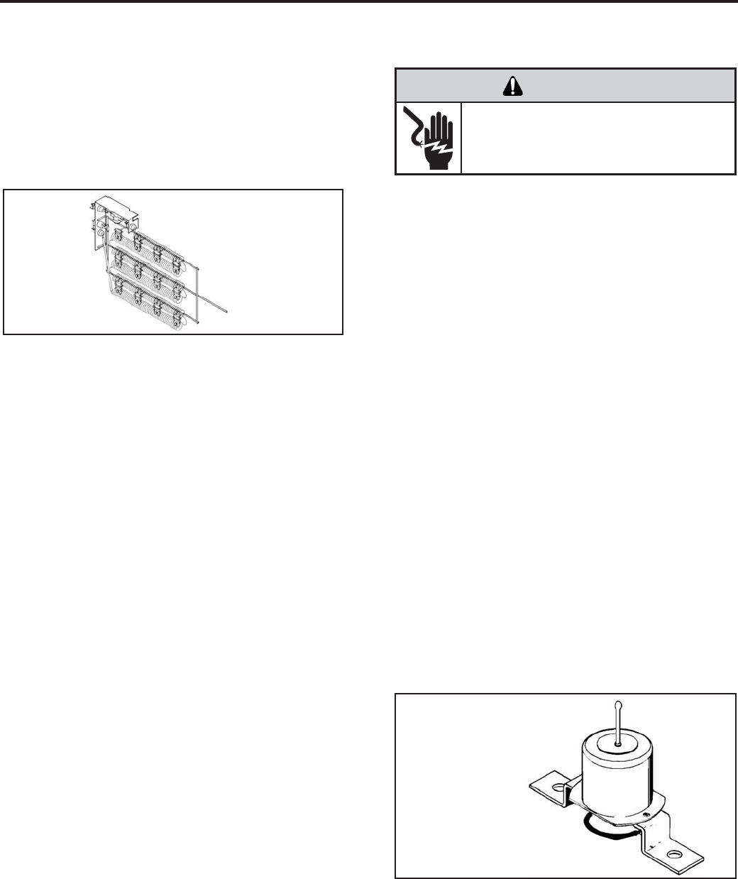
35
HEATING ELEMENT
All heat pumps and electric heat models are equipped
with a heating element with the exception of model
YS10M10. The other “YS” and “ES” models are
equipped with a 3.3 KW element. The “YM” and “EM”
models are equipped with a 4.0 KW element. The
“YL” and “EL” models are equipped with a 5.2 KW
element.
The heating element contains a fuse link and a heater
limit switch. The fuse link is in series with the power
supply and will open and interrupt the power when the
temperature reaches 199°F or a short circuit occurs in
the heating element. Once the fuse link separates, a
new fuse link must be installed.
NOTE: Always replace with the exact
replacement.
The heater element has a high limit control. This
control is a bimetal thermostat mounted in the top of
the heating element.
Should the fan motor fail or fi lter become clogged,
the high limit control will open and interrupt power to
the heater before reaching an unsafe temperature
condition.
The control is designed to open at 110°F ±6°F. Test
continuity below 110°F and for open above 110°F.
HEATING ELEMENT (Heat Pump Models)
The heating element for the “Y” model is energized
by an outdoor thermistor via the electronic control
board. The outdoor defrost thermistor is adjusted at
a predetermined temperature to bring on the heating
element and turn off the compressor. The room
Heating Element
Sample
TESTING THE HEATING ELEMENT
Testing of the elements can be made with an ohmmeter
across the terminals after the connecting wires
have been removed. A cold resistance reading of
approximately 14.5 ohms for the 3.3 KW heater, 11.9
ohms for the 4.0 KW heater and 9.15 ohms for the 5.2
KW heater should be registered.
DRAIN PAN VALVE
During the cooling mode of operation, condensate
which collects in the drain pan is picked up by the con-
denser fan blade and sprayed onto the condenser coil.
This assists in cooling the refrigerant plus evaporating
the water.
During the heating mode of operation, it is necessary
that water be removed to prevent it from freezing during
cold outside temperatures. This could cause the con-
denser fan blade to freeze in the accumulated water
and prevent it from turning.
To provide a means of draining this water, a bellows
type drain valve is installed over a drain opening in the
base pan.
This valve is temperature sensitive and will open when
the outside temperature reaches 40°F. The valve will
close gradually as the temperature rises above 40°F to
fully close at 60°F.
Bellows Assembly
Drain Pan Valve
COMPONENTS TESTING
ELECTRIC SHOCK HAZARD
WARNING
Disconnect power to the unit before
servicing. Failure to follow this warning
could result in serious injury or death.
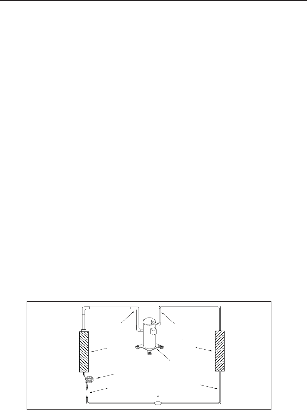
36
Suction
Line
Evaporator
Coil
Metering
Device
Refrigerant
Strainer
Discharge
Line
Condenser
Coil
Compressor
Refrigerant Drier Liquid
Line
A good understanding of the basic operation of the
refrigeration system is essential for the service technician.
Without this understanding, accurate troubleshooting of
refrigeration system problems will be more diffi cult and time
consuming, if not (in some cases) entirely impossible. The
refrigeration system uses four basic principles (laws) in its
operation they are as follows:
1. “Heat always fl ows from a warmer body to a cooler
body.”
2. “Heat must be added to or removed from a substance
before a change in state can occur”
3. “Flow is always from a higher pressure area to a lower
pressure area.”
4. “The temperature at which a liquid or gas changes state
is dependent upon the pressure.”
The refrigeration cycle begins at the compressor. Starting
the compressor creates a low pressure in the suction line
which draws refrigerant gas (vapor) into the compressor.
The compressor then “compresses” this refrigerant, raising
its pressure and its (heat intensity) temperature.
The refrigerant leaves the compressor through the discharge
Line as a hot High pressure gas (vapor). The refrigerant
enters the condenser coil where it gives up some of its
heat. The condenser fan moving air across the coil’s fi nned
surface facilitates the transfer of heat from the refrigerant to
the relatively cooler outdoor air.
When a suffi cient quantity of heat has been removed from
the refrigerant gas (vapor), the refrigerant will “condense”
(i.e. change to a liquid). Once the refrigerant has been
condensed (changed) to a liquid it is cooled even further by
the air that continues to fl ow across the condenser coil.
The RAC design determines at exactly what point (in the
condenser) the change of state (i.e. gas to a liquid) takes
place. In all cases, however, the refrigerant must be
totally condensed (changed) to a Liquid before leaving the
condenser coil.
The refrigerant leaves the condenser Coil through the liquid
line as a warm high pressure liquid. It next will pass through
the refrigerant drier (if so equipped). It is the function of the
drier to trap any moisture present in the system, contaminants,
and large particulate matter.
The liquid refrigerant next enters the metering device. The
metering device is a capillary tube. The purpose of the
metering device is to “meter” (i.e. control or measure) the
quantity of refrigerant entering the evaporator coil.
In the case of the capillary tube this is accomplished (by
design) through size (and length) of device, and the pressure
difference present across the device.
Since the evaporator coil is under a lower pressure (due to
the suction created by the compressor) than the liquid line,
the liquid refrigerant leaves the metering device entering the
evaporator coil. As it enters the evaporator coil, the larger
area and lower pressure allows the refrigerant to expand
and lower its temperature (heat intensity). This expansion is
often referred to as “boiling”. Since the unit’s blower is moving
indoor air across the fi nned surface of the evaporator coil,
the expanding refrigerant absorbs some of that heat. This
results in a lowering of the indoor air temperature, hence the
“cooling” effect.
The expansion and absorbing of heat cause the liquid
refrigerant to evaporate (i.e. change to a gas). Once the
refrigerant has been evaporated (changed to a gas), it is
heated even further by the air that continues to fl ow across
the evaporator coil.
The particular system design determines at exactly what
point (in the evaporator) the change of state (i.e. liquid to a
gas) takes place. In all cases, however, the refrigerant must
be totally evaporated (changed) to a gas before leaving the
evaporator coil.
The low pressure (suction) created by the compressor
causes the refrigerant to leave the evaporator through the
suction line as a cool low pressure vapor. The refrigerant then
returns to the compressor, where the cycle is repeated.
REFRIGERATION SEQUENCE OF OPERATION
37
• R-410A pressure is approximately 60% higher than R-22 pressure.
• R-410A cylinders must not be allowed to exceed 125 F, they may leak or rupture.
• R-410A must never be pressurized with a mixture of air, it may become
fl ammable.
• Servicing equipment and components must be specifi cally designed for use with R-410A and
dedicated to prevent contamination.
• Manifold sets must be equipped with gauges capable of reading 750 psig (high side) and 200
psig (low side), with a 500-psig low-side retard.
• Gauge hoses must have a minimum 750-psig service pressure rating
• Recovery cylinders must have a minimum service pressure rating of 400 psig, (DOT 4BA400
and DOT BW400 approved cylinders).
• POE (Polyol-Ester) lubricants must be used with R-410A equipment.
• To prevent moisture absorption and lubricant contamination, do not leave the refrigeration
system open to the atmosphere longer than 1 hour.
• Weigh-in the refrigerant charge into the high side of the system.
• Introduce liquid refrigerant charge into the high side of the system.
• For low side pressure charging of R-410A, use a charging adaptor.
• Use Friedrich approved R-410A fi lter dryers only.
The following is a list of important considerations when working with R-410A equipment
R-410A SEALED SYSTEM REPAIR CONSIDERATIONS
Do not puncture, heat, expose to fl ame or incinerate.
Only certifi ed refrigeration technicians should
service this equipment.
R410A systems operate at higher pressures than
R22 equipment. Appropriate safe service and
handling practicces must be used.
Only use gauge sets designed for use with R410A.
Do not use standard R22 gauge sets.
WARNING
Refrigeration system under high pressure
38
Proper refrigerant charge is essential to proper unit operation.
Operating a unit with an improper refrigerant charge will
result in reduced performance (capacity) and/or effi ciency.
Accordingly, the use of proper charging methods during
servicing will insure that the unit is functioning as designed
and that its compressor will not be damaged.
Too much refrigerant (overcharge) in the system is just as bad
(if not worse) than not enough refrigerant (undercharge). They
both can be the source of certain compressor failures if they
remain uncorrected for any period of time. Quite often, other
problems (such as low air fl ow across evaporator, etc.) are
misdiagnosed as refrigerant charge problems. The refrigerant
circuit diagnosis chart will assist you in properly diagnosing
these systems.
An overcharged unit will at times return liquid refrigerant
(slugging) back to the suction side of the compressor eventually
causing a mechanical failure within the compressor. This
mechanical failure can manifest itself as valve failure, bearing
failure, and/or other mechanical failure. The specifi c type of
failure will be infl uenced by the amount of liquid being returned,
and the length of time the slugging continues.
Not enough refrigerant (undercharge) on the other hand, will
cause the temperature of the suction gas to increase to the point
where it does not provide suffi cient cooling for the compressor
motor. When this occurs, the motor winding temperature will
increase causing the motor to overheat and possibly cycle open
the compressor overload protector. Continued overheating of
the motor windings and/or cycling of the overload will eventually
lead to compressor motor or overload failure.
Sealed Refrigeration System contains refrigerant
and oil under high pressure.
Proper safety procedures must be followed,
and proper protective clothing must be worn
when working with refrigerants.
Failure to follow these procedures could
result in serious injury or death.
WARNING
HIGH PRESSURE HAZARD
Unplug and/or disconnect all electrical power
to the unit before performing inspections,
maintenances or service.
Failure to do so could result in electric shock,
serious injury or death.
WARNING
RISK OF ELECTRIC SHOCK
R-410A SEALED REFRIGERATION SYSTEM REPAIRS
SEALED SYSTEM REPAIRS TO COOL-ONLY MODELS REQUIRE THE INSTALLATION OF A LIQUID LINE DRIER.
IMPORTANT
EQUIPMENT REQUIRED:
1. Voltmeter
2. Ammeter
3. Ohmmeter
4. E.P.A. Approved Refrigerant Recovery System
5. Vacuum Pump (capable of 200 microns or less
vacuum.)
6. Acetylene Welder
7. Electronic Halogen Leak Detector capable of
detecting HFC (Hydrofl uorocarbon) refrigerants.
8. Accurate refrigerant charge measuring device such
as:
a. Balance Scales - 1/2 oz. accuracy
b. Charging Board - 1/2 oz. accuracy
9. High Pressure Gauge - (0 to 750 lbs.)
10. Low Pressure Gauge - (-30 to 200 lbs.)
11. Vacuum Gauge - (0 - 1000 microns)
12. Facilities for fl owing nitrogen through refrigeration tubing
during all brazing processes.
EQUIPMENT MUST BE CAPABLE OF:
1. Recovering refrigerant to EPA required levels.
2. Evacuation from both the high side and low side of the
system simultaneously.
3. Introducing refrigerant charge into high side of the
system.
4. Accurately weighing the refrigerant charge introduced
into the system.
Refrigerant Charging
NOTE: Because the RAC system is a sealed system, service
process tubes will have to be installed. First install a line tap
and remove refrigerant from system. Make necessary sealed
system repairs and vacuum system. Crimp process tube
line and solder end shut. Do not leave a service valve in the
sealed system.
39
3. Install a process tube to sealed system.
4. Make necessary repairs to system.
5. Evacuate system to 200 microns or less.
6. Weigh in refrigerant with the property quantity of R-410A
refrigerant.
7. Start unit, and verify performance.
8. Crimp the process tube and solder the end shut.
Proper safety procedures must be followed,
and proper protective clothing must be worn
when working with a torch.
Failure to follow these procedures could
result in moderate or serious injury.
Proper safety procedures must be followed,
and proper protective clothing must be worn
when working with liquid refrigerant.
Failure to follow these procedures could
result in minor to moderate injury.
WARNING
CAUTION
BURN HAZARD
FREEZE HAZARD
Proper safety procedures must be followed,
and proper protective clothing must be worn
when working with a torch.
Failure to follow these procedures could
result in moderate or serious injury.
WARNING
BURN HAZARD
Method Of Charging / Repairs
The acceptable method for charging the WallMaster system
is the Weighed in Charge Method. The weighed in charge
method is applicable to all units. It is the preferred method to
use, as it is the most accurate.
The weighed in method should always be used whenever
a charge is removed from a unit such as for a leak repair,
compressor replacement, or when there is no refrigerant
charge left in the unit. To charge by this method, requires the
following steps:
1. Install a piercing valve to remove refrigerant from the
sealedsystem. (Piercing valve must be removed from the
system before recharging.)
2. Recover Refrigerant in accordance with EPA regulations.
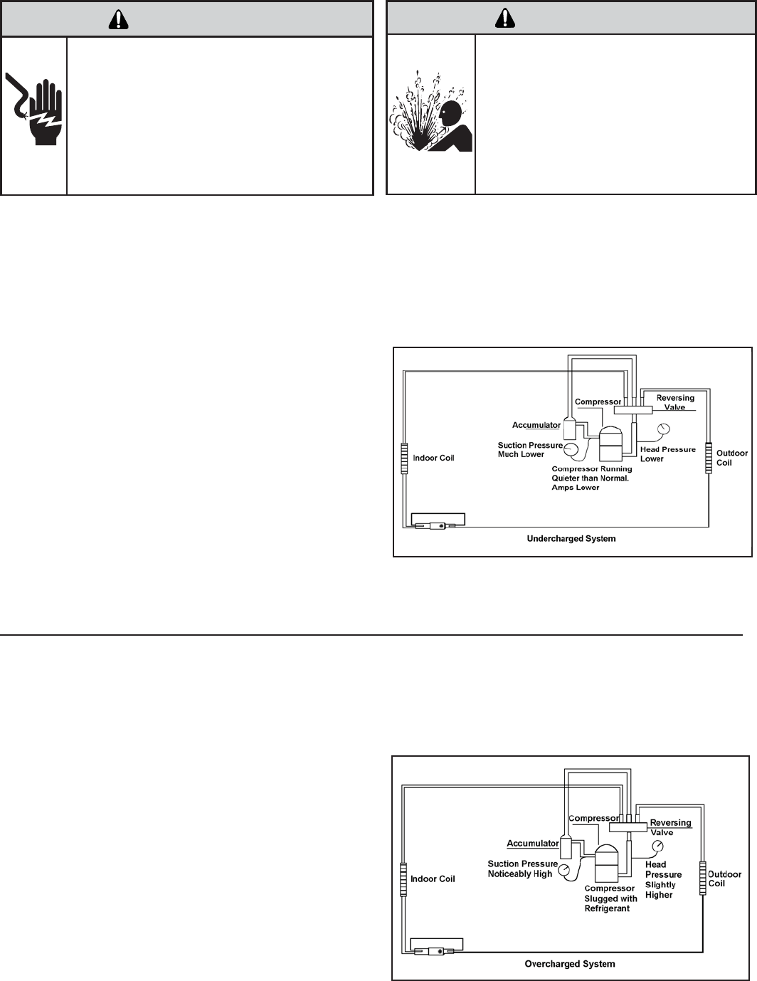
40
Undercharged Refrigerant Systems
An undercharged system will result in poor performance
(low pressures, etc.) in both the heating and cooling
cycle.
Whenever you service a unit with an undercharge of
refrigerant, always suspect a leak. The leak must be
repaired before charging the unit.
To check for an undercharged system, turn the unit on,
allow the compressor to run long enough to establish
working pressures in the system (15 to 20 minutes).
During the cooling cycle you can listen carefully at the exit
of the metering device into the evaporator; an intermittent
hissing and gurgling sound indicates a low refrigerant
charge. Intermittent frosting and thawing of the evaporator
is another indication of a low charge, however, frosting
and thawing can also be caused by insuffi cient air over
the evaporator.
Checks for an undercharged system can be made at
the compressor. If the compressor seems quieter than
normal, it is an indication of a low refrigerant charge.
Overcharged Refrigerant Systems
A check of the amperage drawn by the compressor
motor should show a lower reading. (Check the Unit
Specifi cation.) After the unit has run 10 to 15 minutes,
check the gauge pressures. Gauges connected to system
with an undercharge will have low head pressures and
substantially low suction pressures.
of the evaporator will not be encountered because the
refrigerant will boil later if at all. Gauges connected to
system will usually have higher head pressure (depending
upon amount of over charge). Suction pressure should be
slightly higher.
Compressor amps will be near normal or higher.
Noncondensables can also cause these symptoms. To
confi rm, remove some of the charge, if conditions improve,
system may be overcharged. If conditions don’t improve,
Noncondensables are indicated.
Whenever an overcharged system is indicated, always
make sure that the problem is not caused by air fl ow
problems. Improper air fl ow over the evaporator coil may
indicate some of the same symptoms as an over charged
system.
An overcharge can cause the compressor to fail, since it
would be “slugged” with liquid refrigerant.
The charge for any system is critical. When the compressor
is noisy, suspect an overcharge, when you are sure that
the air quantity over the evaporator coil is correct. Icing
ELECTRIC SHOCK HAZARD
WARNING
Turn off electric power before service or
installation.
Extreme care must be used, if it becomes
necessary to work on equipment with power
applied.
Failure to do so could result in serious injury or
death.
Sealed Refrigeration System contains refrigerant
and oil under high pressure.
Proper safety procedures must be followed,
and proper protective clothing must be worn
when working with refrigerants.
Failure to follow these procedures could
result in serious injury or death.
WARNING
HIGH PRESSURE HAZARD
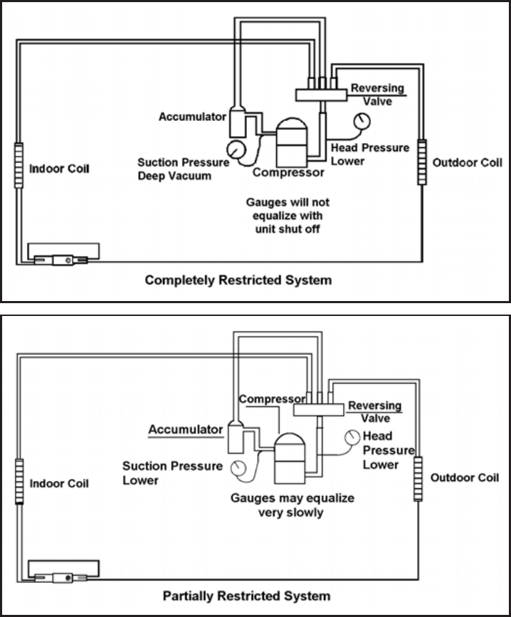
41
Restricted Refrigerant System
Troubleshooting a restricted refrigerant system can be
diffi cult. The following procedures are the more common
problems and solutions to these problems. There are two
types of refrigerant restrictions: Partial restrictions and
complete restrictions.
A partial restriction allows some of the refrigerant to
circulate through the system.
With a complete restriction there is no circulation of
refrigerant in the system.
Restricted refrigerant systems display the same symptoms
as a “low-charge condition.”
When the unit is shut off, the gauges may equalize very
slowly.
Gauges connected to a completely restricted system will
run in a deep vacuum. When the unit is shut off, the gauges
will not equalize at all.
A quick check for either condition begins at the evaporator.
With a partial restriction, there may be gurgling sounds
at the metering device entrance to the evaporator. The
evaporator in a partial restriction could be partially frosted
or have an ice ball close to the entrance of the metering
device. Frost may continue on the suction line back to the
compressor.
Often a partial restriction of any type can be found by feel,
as there is a temperature difference from one side of the
restriction to the other.
With a complete restriction, there will be no sound at the
metering device entrance. An amperage check of the
compressor with a partial restriction may show normal
current when compared to the unit specifi cation. With a
complete restriction the current drawn may be considerably
less than normal, as the compressor is running in a deep
vacuum (no load.) Much of the area of the condenser will
be relatively cool since most or all of the liquid refrigerant
will be stored there.
The following conditions are based primarily on a system
in the cooling mode.
42
METERING DEVICE
Capillary Tube Systems
All units are equipped with capillary tube metering
devices.
Checking for restricted capillary tubes.
1. Connect pressure gauges to unit.
2. Start the unit in the cooling mode. If after a few minutes
of operation the pressures are normal, the check valve
and the cooling capillary are not restricted.
3. Switch the unit to the heating mode and observe the
gauge readings after a few minutes running time. If
the system pressure is lower than normal, the heating
capillary is restricted.
4. If the operating pressures are lower than normal in both
the heating and cooling mode, the cooling capillary is
restricted.
Proper safety procedures must be followed,
and proper protective clothing must be worn
when working with a torch.
Failure to follow these procedures could
result in moderate or serious injury.
WARNING
BURN HAZARD
HERMETIC COMPONENTS CHECK
One-way Check Valve
(Heat Pump Models)
CHECK VALVE
A unique two-way check valve is used on the reverse cycle
heat pumps. It is pressure operated and used to direct the
fl ow of refrigerant through a single fi lter drier and to the
proper capillary tube during either the heating or cooling
cycle.
NOTE: The slide (check) inside the valve is made of tefl on.
Should it become necessary to replace the check valve,
place a wet cloth around the valve to prevent overheating
during the brazing operation.
CHECK VALVE OPERATION
In the cooling mode of operation, high pressure liquid enters
the check valve forcing the slide to close the opposite port
(liquid line) to the indoor coil. Refer to refrigerant fl ow chart.
This directs the refrigerant through the fi lter drier and cooling
capillary tube to the indoor coil.
In the heating mode of operation, high pressure refrigerant
enters the check valve from the opposite direction, closing
the port (liquid line) to the outdoor coil. The fl ow path of
the refrigerant is then through the fi lter drier and heating
capillary to the outdoor coil.
Failure of the slide in the check valve to seat properly in
either mode of operation will cause fl ooding of the cooling
coil. This is due to the refrigerant bypassing the heating or
cooling capillary tube and entering the liquid line.
COOLING MODE
In the cooling mode of operation, liquid refrigerant from
condenser (liquid line) enters the cooling check valve
forcing the heating check valve shut. The liquid refrigerant
is directed into the liquid dryer after which the refrigerant
is metered through cooling capillary tubes to evaporator.
(Note: liquid refrigerant will also be directed through the
heating capillary tubes in a continuous loop during the
cooling mode).
HEATING MODE
In the heating mode of operation, liquid refrigerant from
the indoor coil enters the heating check valve forcing the
cooling check valve shut. The liquid refrigerant is directed
into the liquid dryer after which the refrigerant is metered
through the heating capillary tubes to outdoor coils. (Note:
liquid refrigerant will also be directed through the cooling
capillary tubes in a continuous loop during the heating
mode).
CUT/SEVER HAZARD
WARNING
Be careful with the sharp edges and corners.
Wear protective clothing and gloves, etc.
Failure to do so could result in serious injury.
43
NOTE: System operating pressures must be near
normal before valve can shift.
REVERSING VALVE DESCRIPTION/OPERATION
The Reversing Valve controls the direction of refrigerant
fl ow to the indoor and outdoor coils. It consists of a
pressure-operated, main valve and a pilot valve actuated
by a solenoid plunger. The solenoid is energized during the
heating cycle only. The reversing valves used in the RAC
system is a 2-position, 4-way valve.
The single tube on one side of the main valve body is the
high-pressure inlet to the valve from the compressor. The
center tube on the opposite side is connected to the low
pressure (suction) side of the system. The other two are
connected to the indoor and outdoor coils. Small capillary
tubes connect each end of the main valve cylinder to the
“A” and “B” ports of the pilot valve. A third capillary is a common
return line from these ports to the suction tube on the main
valve body. Four-way reversing valves also have a capillary
tube from the compressor discharge tube to the pilot valve.
The piston assembly in the main valve can only be shifted
by the pressure differential between the high and low sides
of the system. The pilot section of the valve opens and
closes ports for the small capillary tubes to the main valve
to cause it to shift.
ELECTRIC SHOCK HAZARD
WARNING
Disconnect power to the unit before servicing.
Failure to follow this warning could result in
serious injury or death.
44
Reversing Valve in Heating Mode
TESTING THE REVERSING VALVE
SOLENOID COIL
The solenoid coil is an electromagnetic type coil mounted
on the reversing valve and is energized during the
operation of the compressor in the heating cycle.
1. Turn off high voltage electrical power to unit.
2. Unplug line voltage lead from reversing valve coil.
3. Check for electrical continuity through the coil. If you
do not have continuity replace the coil.
4. Check from each lead of coil to the copper liquid line
as it leaves the unit or the ground lug. There should
be no continuity between either of the coil leads
and ground; if there is, coil is grounded and must be
replaced.
5. If coil tests okay, reconnect the electrical leads.
6. Make sure coil has been assembled correctly.
NOTE: Do not start unit with solenoid coil removed from
valve, or do not remove coil after unit is in operation. This
will cause the coil to burn out.
CHECKING THE REVERSING VALVE
NOTE: You must have normal operating pressures before
the reversing valve can shift.
Check the operation of the valve by starting the system
and switching the operation from “Cooling” to “Heating”
and then back to “Cooling”. Do not hammer on valve.
Occasionally, the reversing valve may stick in the heating
or cooling position or in the mid-position.
When sluggish or stuck in the mid-position, part of the
discharge gas from the compressor is directed back to the
suction side, resulting in excessively high suction pressure.
ELECTRIC SHOCK HAZARD
WARNING
Unplug and/or disconnect all electrical power
to the unit before performing inspections,
maintenances or service.
Failure to do so could result in electric shock,
serious injury or death.
Sealed Refrigeration System contains refrigerant
and oil under high pressure.
Proper safety procedures must be followed,
and proper protective clothing must be worn
when working with refrigerants.
Failure to follow these procedures could
result in serious injury or death.
WARNING
HIGH PRESSURE HAZARD
Should the valve fail to shift from coooling to heating,
block the air fl ow through the outdoor coil and allow the
discharge pressure to build in the system. Then switch
the system from heating to cooling.
If the valve is stuck in the heating position, block the air
fl ow through the indoor coil and allow discharge pressure
to build in the system. Then switch the system from
heating to cooling.
Should the valve fail to shift in either position after
increasing the discharge pressure, replace the valve.
Dented or damaged valve body or capillary tubes can
prevent the main slide in the valve body from shifting.
If you determing this is the problem, replace the reversing
valve.
After all of the previous inspections and checks have
been made and determined correct, then perform the
“Touch Test” on the reversing valve.
45
8. Pressurize sealed system with a combination of R-410A
and nitrogen and check for leaks, using a suitable leak
detector. Recover refrigerant per EPA guidelines.
9. Once the sealed system is leak free, install solenoid coil
on new valve and charge the sealed system by weighing
in the proper amount and type of refrigerant as shown
on rating plate. Crimp the process tubes and solder the
ends shut. Do not leave Schrader or piercing valves in
the sealed system.
NOTE: When brazing a reversing valve into the system, it is
of extreme importance that the temperature of the valve does
not exceed 250°F at any time.
Wrap the reversing valve with a large rag saturated with
water. “Re-wet” the rag and thoroughly cool the valve after
each brazing operation of the four joints involved.
The wet rag around the reversing valve will eliminate
conduction of heat to the valve body when brazing the line
connection.
6. Protect new valve body from heat while brazing with plastic
heat sink (Thermo Trap) or wrap valve body with wet
rag.
7. Fit all lines into new valve and braze lines into new
valve.
Procedure For Changing Reversing Valve
1. Install Process Tubes. Recover refrigerant from sealed
system. PROPER HANDLING OF RECOVERED
REFRIGERANT ACCORDING TO EPA REGULATIONS
IS REQUIRED.
2. Remove solenoid coil from reversing valve. If coil is to
be reused, protect from heat while changing valve.
3. Unbraze all lines from reversing valve.
4. Clean all excess braze from all tubing so that they will
slip into fi ttings on new valve.
5. Remove solenoid coil from new valve.
The use of a torch requires extreme care and proper
judgment. Follow all safety recommended precautions
and protect surrounding areas with fi re proof materials.
Have a fi re extinguisher readily available. Failure to follow
this notice could result in moderate to serious property
damage.
NOTICE
FIRE HAZARD
Touch Test in Heating/Cooling Cycle
The only definite indications that the slide is in the mid-
position is if all three tubes on the suction side of the valve
are hot after a few minutes of running time.
NOTE: A condition other than those illustrated above, and
on Page 44, indicate that the reversing valve is not shifting
properly. Both tubes shown as hot or cool must be the same
corresponding temperature.
Certain unit components operate at
temperatures hot enough to cause burns.
Proper safety procedures must be followed,
and proper protective clothing must be
worn.
Failure to follow these procedures could
result in minor to moderate injury.
WARNING
BURN HAZARD
The use of nitrogen requires a pressure
regulator. Follow all safety procedures and
wear protective safety clothing etc.
Failure to follow proper safety procedures
could result in serious injury or death.
WARNING
EXPLOSION HAZARD
Sealed Refrigeration System contains refrigerant
and oil under high pressure.
Proper safety procedures must be followed,
and proper protective clothing must be worn
when working with refrigerants.
Failure to follow these procedures could
result in serious injury or death.
WARNING
HIGH PRESSURE HAZARD
46
Locked Rotor Voltage (L.R.V.) Test
Locked rotor voltage (L.R.V.) is the actual voltage available
at the compressor under a stalled condition.
Single Phase Connections
Disconnect power from unit. Using a voltmeter, attach one
lead of the meter to the run “R” terminal on the compressor
and the other lead to the common “C” terminal of the com-
pressor. Restore power to unit.
Determine L.R.V.
Start the compressor with the volt meter attached; then stop
the unit. Attempt to restart the compressor within a couple
of seconds and immediately read the voltage on the meter.
The compressor under these conditions will not start and will
usually kick out on overload within a few seconds since the
pressures in the system will not have had time to equalize.
Voltage should be at or above minimum voltage of 197 VAC,
as specifi ed on the rating plate. If less than minimum, check
for cause of inadequate power supply; i.e., incorrect wire
size, loose electrical connections, etc.
COMPRESSOR CHECKS
ELECTRIC SHOCK HAZARD
WARNING
Turn off electric power before service or
installation. Extreme care must be used, if it
becomes necessary to work on equipment with
power applied.
Failure to do so could result in serious injury or
death.
Heat generated within the compressor shell, usually due
to recycling of the motor, is slow to dissipate. It may take
anywhere from a few minutes to several hours for the
overload to reset.
Checking the Overloads
External Overloads
With power off, remove the leads from compressor
terminals. If the compressor is hot, allow the overload
to cool before starting check. Using an ohmmeter, test
continuity across the terminals of the external overload.
If you do not have continuity; this indicates that the
overload is open and must be replaced.
Interrnal Overloads
Some model compressors are equipped with an internal
overload. The overload is embedded in the motor
windings to sense the winding temperature and/or current
draw. The overload is connected in series with the
common motor terminal.
Should the internal temperature and/or current draw
become excessive, the contacts in the overload will
open, turning off the compressor. The overload will
automatically reset, but may require several hours before
the heat is dissipated.
Checking the Internal Overload
1. With no power to unit, remove the leads from the
compressor terminals.
2. Using an ohmmeter, test continuity between terminals
C-S and C-R. If no continuity, the compressor overload is
open and the compressor must be replaced.
Amperage (L.R.A.) Test
The running amperage of the compressor is the most
important of these readings. A running amperage higher
than that indicated in the performance data indicates that a
problem exists mechanically or electrically.
Single Phase Running and L.R.A. Test
NOTE: Consult the specifi cation and performance section
for running amperage. The L.R.A. can also be found on the
rating plate.
Select the proper amperage scale and clamp the meter
probe around the wire to the “C” terminal of the compressor.
Turn on the unit and read the running amperage on the
meter. If the compressor does not start, the reading will
indicate the locked rotor amperage (L.R.A.).
Overloads
The compressor is equipped with either an external or
internal overload which senses both motor amperage
and winding temperature. High motor temperature or
amperage heats the overload causing it to open, breaking
the common circuit within the compressor.
Certain unit components operate at
temperatures hot enough to cause burns.
Proper safety procedures must be followed,
and proper protective clothing must be
worn.
Failure to follow this warning could result
in moderate to serious injury.
WARNING
BURN HAZARD
ELECTRIC SHOCK HAZARD
WARNING
Turn off electric power before service or
installation. Extreme care must be used, if it
becomes necessary to work on equipment
with power applied.
Failure to do so could result in serious injury or
death.
47
Single Phase Resistance Test
tes dna slanimret rosserpmoc eht morf sdael eht evomeR
the ohmmeter on the lowest scale (R x 1).
nommoc slanimret morf retemmho eht fo sdael eht hcuoT
retemmho eht fo sdael eht hcuot ,txeN .)”S“ ot ”C“( trats ot
from terminals common to run (“C” to “R”).
Add values “C” to “S” and “C” to “R” together and
.)”R“ ot ”S“( slanimret n
ur ot trats morf ecnatsiser kcehc
Resistance “S” to “R” should equal the total of “C” to “S”
and “C” to “R.”
In a single phase PSC compressor motor, the highest
ot ”S“( snoitcennoc nur eht ot trats eht morf eb lliw eulav
e
ht ot trats eht morf si ecnatsiser tsehgih txen ehT .)”R“
common connections (“S” to “C”). The lowest resistance
is from the run to common. (“C” to “R”) Before replacing a
compressor, check to be sure it is defective.
GROUND TEST
Use an ohmmeter set on its highest scale. Touch one
lead to the compressor body (clean point of contact as
a good connection is a must) and the other probe in turn
to each compressor terminal. If a reading is obtained the
compressor is grounded and must be replaced.
Check the complete electrical system to the compressor
and compressor internal electrical system, check to be
certain that compressor is not out on internal overload.
Complete evaluation of the system must be made
whenever you suspect the compressor is defective. If
the compressor has been operating for sometime, a
careful examination must be made to determine why the
compressor failed.
Many compressor failures are caused by the following
conditions:
1. Improper air flow over the evaporator.
2. Overcharged refrigerant system causing liquid to be
returned to the compressor.
3. Restricted refrigerant system.
4. Lack of lubrication.
5. Liquid refrigerant returning to compressor causing oil
to be washed out of bearings.
6. Noncondensables such as air and moisture in
the system. Moisture is extremely destructive to a
refrigerant system.
7. Capacitor (see page 34).
CHECKING COMPRESSOR EFFICIENCY
The reason for compressor inefficiency is normally due
to broken or damaged suction and/or discharge valves,
reducing the ability of the compressor to pump refrigerant
gas.
This condition can be checked as follows:
1. Install a piercing valve on the suction and discharge or
liquid process tube.
2. Attach gauges to the high and low sides of the system.
3. Start the system and run a “cooling or heating perfor
-
mance test.” If test shows:
A. Below normal high side pressure
B. Above normal low side pressure
C. Low temperature difference across coil
The compressor valves are faulty - replace the
compressor.
ELECTRIC SHOCK HAZARD
WARNING
Turn off electric power before service or
installation. Extreme care must be used, if it
becomes necessary to work on equipment
with power applied.
Failure to do so could result in serious injury or
death.
Sealed Refrigeration System contains refrigerant
and oil under high pressure.
Proper safety procedures must be followed,
and proper protective clothing must be worn
when working with refrigerants.
Failure to follow these procedures could
result in serious injury or death.
WARNING
HIGH PRESSURE HAZARD
48
Recommended procedure for compressor
replacement
1. Be certain to perform all necessary electrical and
refrigeration tests to be sure the compressor is
actually defective before replacing.
2. Recover all refrigerant from the system though
the process tubes. PROPER HANDLING OF
RECOVERED REFRIGERANT ACCORDING TO
EPA REGULATIONS IS REQUIRED. Do not use
gauge manifold for this purpose if there has been
a burnout. You will contaminate your manifold and
hoses. Use a Schrader valve adapter and copper
tubing for burnout failures.
3. After all refrigerant has been recovered, disconnect
suction and discharge lines from the compressor and
remove compressor. Be certain to have both suction
and discharge process tubes open to atmosphere.
4. Carefully pour a small amount of oil from the suction
stub of the defective compressor into a clean
container.
9. Evacuate the system with a good vacuum pump capable
of a fi nal vacuum of 200 microns or less. The system
should be evacuated through both liquid line and suction
line gauge ports. While the unit is being evacuated, seal
all openings on the defective compressor. Compressor
manufacturers will void warranties on units received not
properly sealed. Do not distort the manufacturers tube
connections.
10. Recharge the system with the correct amount of
refrigerant. The proper refrigerant charge will be
found on the unit rating plate. The use of an accurate
measuring device, such as a charging cylinder,
electronic scales or similar device is necessary.
COMPRESSOR REPLACEMENT
5. Using an acid test kit (one shot or conventional kit), test
the oil for acid content according to the instructions
with the kit.
6. If any evidence of a burnout is found, no matter how
slight, the system will need to be cleaned up following
proper procedures.
7. Install the replacement compressor.
8. Pressurize with a combination of R-410A and nitrogen
and leak test all connections with an electronic or
Halide leak detector. Recover refrigerant and repair
any leaks found.
Repeat Step 8 to insure no more leaks are present.
Unplug and/or disconnect all electrical power
to the unit before performing inspections,
maintenances or service.
Failure to do so could result in electric shock,
serious injury or death.
WARNING
RISK OF ELECTRIC SHOCK
Sealed Refrigeration System contains refrigerant
and oil under high pressure.
Proper safety procedures must be followed,
and proper protective clothing must be worn
when working with refrigerants.
Failure to follow these procedures could
result in serious injury or death.
WARNING
HIGH PRESSURE HAZARD
Extreme care, proper judgment and all safety
procedures must be followed when testing,
troubleshooting, handling or working around
unit while in operation with high temperature
components. Wear protective safety aids
such as: gloves, clothing etc.
Failure to do so could result in serious burn
injury.
WARNING
HIGH TEMPERATURES
The use of a torch requires extreme care and proper
judgment. Follow all safety recommended precautions
and protect surrounding areas with fi re proof materials.
Have a fi re extinguisher readily available. Failure to follow
this notice could result in moderate to serious property
damage.
NOTICE
FIRE HAZARD
The use of nitrogen requires a pressure
regulator. Follow all safety procedures and
wear protective safety clothing etc.
Failure to follow proper safety procedures
result in serious injury or death.
WARNING
EXPLOSION HAZARD
Proper safety procedures must be followed,
and proper protective clothing must be worn
when working with liquid refrigerant.
Failure to follow these procedures could
result in minor to moderate injury.
CAUTION
FREEZE HAZARD
49
1.
2.
3.
4.
5.
ELECTRIC SHOCK HAZARD
WARNING
Turn off electric power before service or
installation.
Failure to do so may result in personal injury,
or death.
Sealed Refrigeration System contains refrigerant
and oil under high pressure.
Proper safety procedures must be followed,
and proper protective clothing must be worn
when working with refrigerants.
Failure to follow these procedures could
result in serious injury or death.
WARNING
HIGH PRESSURE HAZARD
The use of nitrogen requires a pressure
regulator. Follow all safety procedures and
wear protective safety clothing etc.
Failure to follow proper safety procedures
result in serious injury or death.
WARNING
EXPLOSION HAZARD
Recover all refrigerant and oil from the system.
Remove compressor, capillary tube and filter drier
from the system.
Flush evaporator condenser and all connecting
tubing with dry nitrogen or equivalent. Use approved
flushing agent to remove all contamination from
system. Inspect suction and discharge line for
carbon deposits. Remove and clean if necessary.
Ensure all acid is neutralized.
Reassemble the system, including new drier strainer
and capillary tube.
Proceed with step 8-10 on previous page.
SPECIAL PROCEDURE IN THE CASE OF MOTOR
COMPRESSOR BURNOUT
Basically, troubleshooting and servicing rotary compres-
sors is the same as on the reciprocating compressor with
only one main exception:
NEVER, under any circumstances, liquid charge a rotary-
compressor through the LOW side. Doing so would cause
permanent damage to the new compressor.
ROTARY AND SCROLL COMPRESSOR SPECIAL
TROUBLESHOOTING AND SERVICE
50
ROUTINE MAINTENANCE
COILS AND BASE PAN
The indoor coil (evaporator coil), the outdoor coil
(condenser coil) and base pan should be inspected
periodically (yearly or bi-yearly) and cleaned of all
debris (lint, dirt, leaves, paper, etc.). Clean the coils
and base pan with a soft brush and compressed air
or vacuum. If using a pressure washer, be careful
not to bend the aluminium fi n pack. Use a sweeping
up and down motion in the direction of the vertical
aluminum fi n pack when pressure cleaning coils.
Cover all electrical components to protect them from
water or spray. Allow the unit to dry thoroughly before
reinstalling it in the sleeve.
BLOWER WHEEL / HOUSING / CONDENSER FAN /
SHROUD
Inspect the indoor blower and its housing, evaporator
blade, condenser fan blade and condenser shroud
periodically (yearly or bi-yearly) and clean of all debris
(lint, dirt, mold, fungus, etc.). Clean the blower housing
area and blower wheel with an antibacterial / antifungal
cleaner. Use a biodegradable cleaning agent and
degreaser on condenser fan and condenser shroud.
Use warm or cold water when rinsing these items.
Allow all items to dry thoroughly before reinstalling
them.
ELECTRONIC / ELECTRICAL / MECHANICAL
Periodically (at least yearly or bi-yearly): inspect
all control components: electronic, electrical and
mechanical, as well as the power supply. Use proper
testing instruments (voltmeter, ohmmeter, ammeter,
wattmeter, etc.) to perform electrical tests. Use an air
conditioning or refrigeration thermometer to check
room, outdoor and coil operating temperatures.
BLOWER/FAN MOTOR
The motor is permanently lubricated.
AIR FILTER
The air fi lter should be inspected weekly and cleaned
if needed by vacuuming with a dust attachment or
by cleaning in the sink using warm water and a mild
dishwashing detergent. Dry the fi lter thoroughly before
reinstalling. Use caution as the coil surface can be sharp.
TO REMOVE, WASH AND REPLACE FILTER
Lower front panel. Use handle on fi lter to fl ex fi lter
up and out of retainer. Remove fi lter from unit. Clean
fi lter monthly or more frequently if needed. Refer to
accessories section for fi lter options.
Units are to be inspected and serviced by qualifi ed service
personnel only. Use proper protection on surrounding
property. Failure to follow this notice could result in
moderate or serious property damage.
NOTICE
EXCESSIVE WEIGHT HAZARD
WARNING
Use two people to lift or carry the unit, and wear
proper protective clothing.
Failure to do so may result in personal injury.
Do not use a caustic coil cleaning agent on coils or base
pan. Use a biodegradable cleaning agent and degreaser,
to prevent damage to the coil and/or base pan.
NOTICE
ELECTRIC SHOCK HAZARD
WARNING
Turn off electric power before inspections,
maintenances, or service.
Extreme care must be used, if it becomes
necessary to work on equipment with power
applied.
Failure to do so could result in serious injury
or death.
CUT/SEVER HAZARD
WARNING
Be careful with the sharp edges and corners.
Wear protective clothing and gloves, etc.
Failure to do so could result in serious injury.
NOTE: .napesabrosliocnotnegagninaelclioccitsuacaesutonoD
Use a biodegradable cleaning agent and degreaser. The use
of harsh c leaning materials may lead to deterioration o f the
NOTE: It is extremely important to insure that none of the electrical
and/or electronic parts of the unit get wet. Be sure to cover all
electrical components to protect them from water or spray.
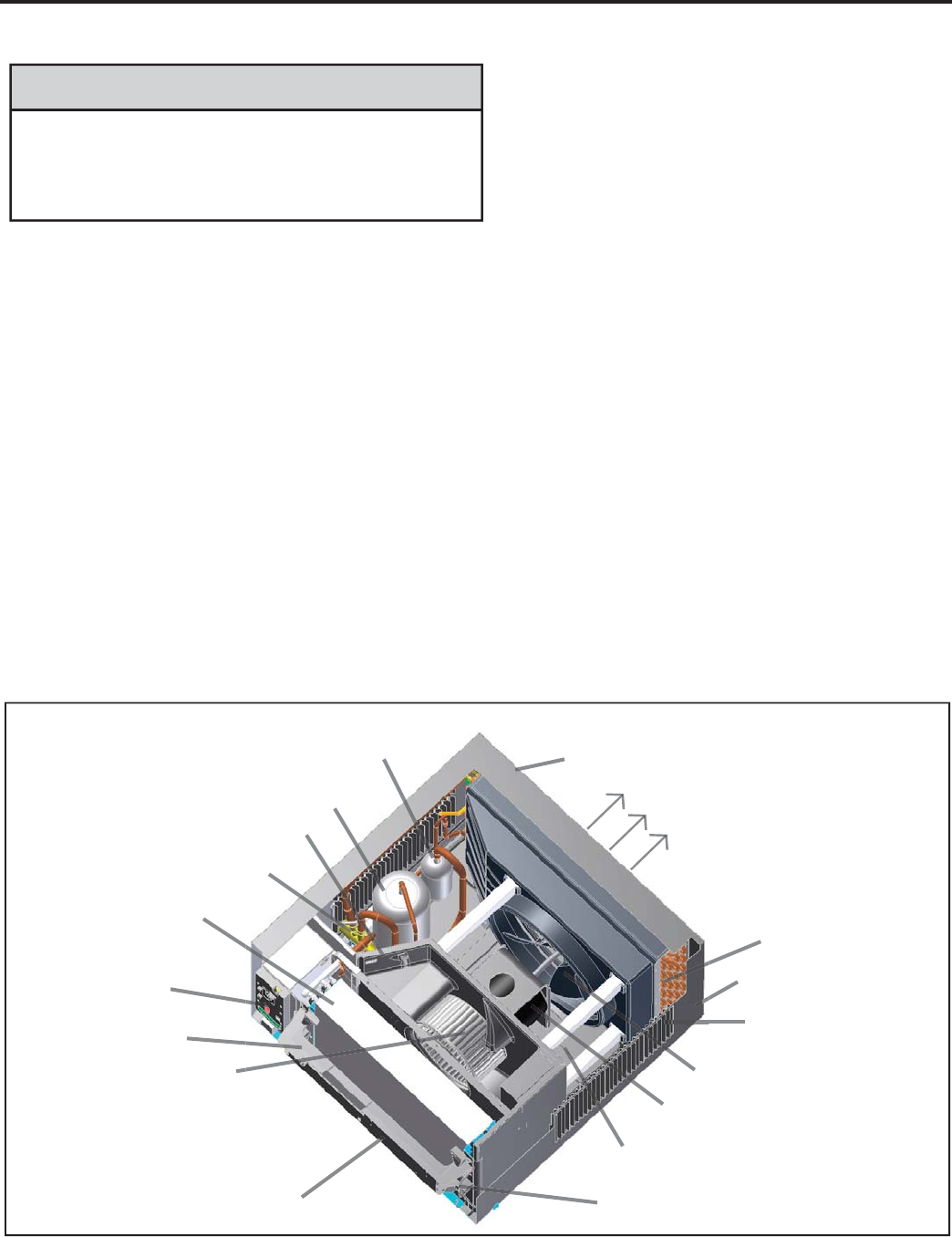
51
SLEEVE / DRAIN
Inspect the sleeve and drain system periodically (at least yearly or bi-yearly) and clean of all obstructions and
debris. Clean both areas with an antibacterial and antifungal cleaner. Rinse both items thoroughly with water and
ensure that the drain outlets are operating correctly. Check the sealant around the sleeve and reseal areas as
needed.
DECORATIVE FRONT COVER
Clean the front cover when needed. Use a mild detergent. Wash and rinse with warm water. Allow it to dry
thoroughly before reinstalling it in the chassis.
The decorative front and the cabinet can be cleaned with warm water and a mild liquid detergent. Do NOT use
solvents or hydrocarbon based cleaners such as acetone, naphtha, gasoline, benzene, etc.
Use a damp (not wet) cloth when cleaning the control area to prevent water from entering the unit, and possibly
damaging the electronic control.
CLEARANCES
Inspect the surrounding area (inside and outside) to ensure that the unit’s clearances have not been compromised or
altered.
ROUTINE MAINTENANCE (Continued)
Do not drill holes in the bottom of the drain pan or the
underside of the unit. Not following this notice could
result in damage to the unit or condensate water leaking
inappropriately which could cause water damage to
surrounding property.
NOTICE
Compressor
Fresh Air Vent
Evaporator Coil
Electronic Control
Board
Control Key Pad
Support Bar
Blower Wheel
Air Intake From
Sides and Bottom
Control Key Pad
(User Interface) Chassis Pull
Out Handle
Base Pan
Fan Blade
Fan/Blower Motor
Air Intake Vents
Sleeve
Condenser Coil
Discharge Air
Outdoor Grille
Accumulator
Reversing Valve
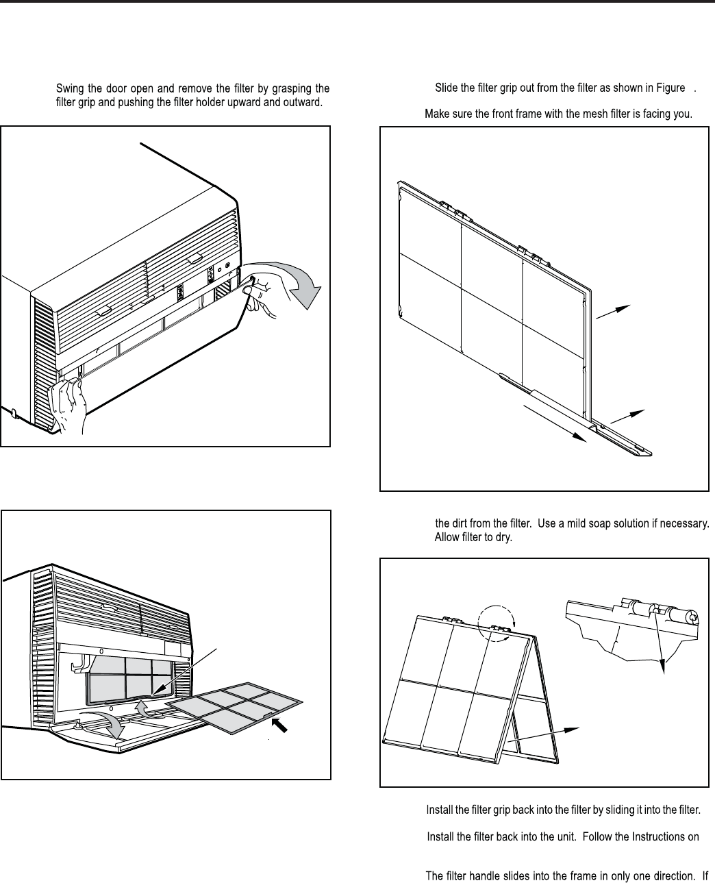
52
ROUTINE MAINTENANCE (Continued)
Standard Filter Cleaning Installation Instructions
STEP 1.
FILTER
FILTER
GRIP
STEP 3. Swing the front frame open. Clean the front frame by washing
STEP 2.
NOTE:
HANDLE
FILTER
GRIP
TOP TAB
FRONT
FRAME WITH
STANDARD
MESH FILTER
A
Figure 1 Figure 3
Figure 4
Figure 2
STEP 4.
NOTE:
the tab in the frame stops the handle from sliding in, sl
3
ide the
STEP 5.
the inside of the front door.
filter halfway up, tilt it towards the front of you, then gently slide
it up fully. Do not force the handle into the frame.
Remove the filter by grabbing it from its handle, lifting it up and swinging
it out.
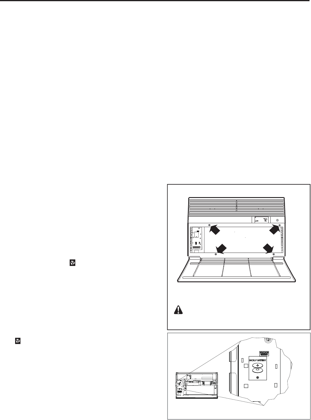
53
Ensure that the circuit breaker(s) or fuse(s) and supply circuit wire
size have been sized correctly. If the unit was supplied with a power
supply cord, insure that it is stored properly.
Ensure that the entire installation is in compliance with all applicable
national and local codes and ordinances having jurisdiction.
Secure components and accessories, such as a decorative front
cover.
Start the unit and check for proper operation of all components in
each mode of operation.
Instruct the owner or operator of the units operation, and the
manufacturer's Routine Maintenance.
NOTE: A log for recording the dates of maintenance and/or service is
recommended.
Present the owner or operator of the equipment with the name,
address and telephone number of the Authorized Friedrich Warranty
Service Company in the area for future reference if necessary.
NOTE: This is a warm weather appliance
The air conditioner is designed to cool in warm weather when the outside
temperature is above 60° F (15.6° C) and below 115° F (46.1° C), so it won't
cool a room if it is already cool outside. If you want to cool a room in the
spring or fall, select the FAN ONLY mode and set the Fresh Air/Exhaust
air control to Fresh Air. This will bring in a supply of cooler outside air.
Condensation is normal
Air conditioners actually pump the heat and humidity from your room to the
outside. Humidity becomes water, and your air conditioner will use most of
the water to keep the outside coil cool. If there is excessive humidity, there
may be excess water that will drip outside. This is normal operation.
Frosting
This usually occurs because of insuffi cient airfl ow across the coils, a dirty
fi lter, cool damp weather, or all of these. Set the SYSTEM mode to FAN
ONLY and the frost will disappear. Setting the thermostat a little warmer
will probably prevent the frosting from recurring.
Noises
All air conditioners make some noise. Friedrich units are designed to operate
as quietly as possible. An air conditioner mounted in a wall is quieter than
one mounted in a window. It is important to ensure that the chassis seal
gasket is properly installed (refer to installation instructions).
Heat pumps operate differently
If your unit is a "Y", or heat pump model, there are some things that you
will want to be aware of. Some functions of a heat pump differ from your
unit when it is used for heating:
It is normal for ice to form on the outdoor coil of the heat pump. 1.
Moisture in the outside air, passing over the coil when very cold,
will form ice.
If the outdoor temperature drops below 37° F (3° C), your heat 2.
pump will automatically turn on the electric resistance heat. When
the temperature rises to 40° F (4° C), the compressor will resume
the heat pump operation. If your unit is a 115 volt model (YS10),
it is designed for use in warmer climates and does not have an
electrical heat feature, and will not provide adequate heat below
37° F (2.8° C).
After Maintenance/Repair
Start-up Checklist and Notes
Inspect and ensure that all components and accessories have been
installed properly and that they have not been damaged during the
installation progress.
Check the condensate water drain(s) to ensure that they are adequate
for the removal of condensate water, and that they meet the approval
of the end user.
Ensure that all installation instructions concerning clearances around
the unit have been adhered to. Check to ensure that the unit air fi lter,
indoor coil, and outdoor coil are free from any obstructions.
ROUTINE MAINTENANCE (Continued)
FRR010
1. USE HAND TOOLS WHEN INSTALLING AND
REMOVING FRONT PANEL.
DO NOT OVERTIGHTEN SCREWS.
2. DISCONNECT POWER AND FOLLOW ALL
LABELED WARNINGS WHEN FRONT PANEL
IS REMOVED.
USE HAND TOOLS
DO NOT OVER TIGHTEN
Figure
Figure
CONTROL PANEL BATTERY CHANGE
PROCEDURE
Remove the grille, by loosening four (4) captive screws (See Figure 1).
Remove one (1) screw on the battery retaining door (See Figure 2). Remove
and replace the battery (CR2450). Reinstall the battery retaining door. Align
the grille guide pins then tighten the four (4) captive screws. Before closing
the grille panel door, check the fi lter. Clean or replace it as necessary.
Battery type: Lithium, 3 Volts, #CR2450
Figure 1
Figure 2

54
Service and Assistance
Before calling for service, please check the “Troubleshooting Tips” section
on pages 40 and 41. This may help you to fi nd the answer to your problem,
avoid unnecessary service calls, and save you the cost of a service call if
the problem is not due to the product itself. If you have checked the “Basic
Troubleshooting” section and still need help, it is available as follows:
You can fi nd the name of your local Authorized Service Provider by visiting
our web site at www.friedrich.com.
If you require further assistance
You can call the Customer Support Call Center at 1-800-541-6645.
Before calling, please make sure that you have the complete model and
serial number, and date of purchase of your equipment available. By
providing us with this information, we will be better able to assist you.
Our specialists are able to assist you with:
Specifi cations and Features of our equipment.
Referrals to dealers, and distributors.
Use and Care Information.
Recommended maintenance procedures.
Installation information.
Referrals to Authorized Service Providers and Parts depots.
Available Accessories
DC-2 Drain Kit – Part No. 01900235
In some installations, excess condensate water caused by extremely humid
conditions, may result in an undesirable water drip such as on a patio or
over an entryway. MODEL DC-2 DRAIN KIT (Part No. 01900-235) can be
installed to drain excess condensation to an alternate location.
Carbon Filter Kits
The kits vary depending on the chassis size (small, medium, large). Each
kit contains three (3) fi lters.
WCFS – Carbon fi lter kit for small chassis models.
WCFM – Carbon fi lter kit for medium chassis models.
WCFL – Carbon fi lter kit for large chassis models.
Remote Wall Thermostats
RT4 – Digital wall thermostat hard wired with single speed fan.
RT5 – Digital wall thermostat hard wired with a digital display, two fan speed
selection, fi lter check light, temperature limiting, status indicator light, room
temperature offset, backlight and battery backup.
Window Installation Kits (Standard in Kühl
Models without Heat)
KWIKS – For all ES and YS models.
KWIKM – For all EM and YM models.
KWIKL – For all EL and YL models.
See www.friedrich.com for additional accessories for your unit.
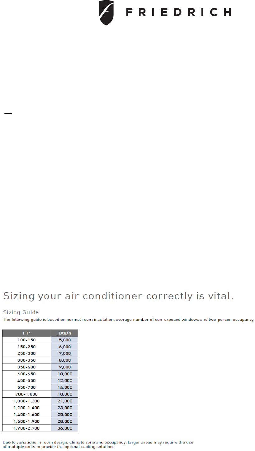
55
ROOM AIR CONDITIONER UNIT PERFORMANCE TEST DATA SHEET
JOB NAME________________________________ TECHS NAME____________________________________
DATE: _______________ MODEL:_______________ SERIAL:________________
HOW IS ALL OF THE INSTALLATION? GOOD BAD
YES NO
IS A C HAS S IS S E AL GAS K E T INTALLE D ?
IS THE FRESH/EXAUST AIR VENT OPEN?
IS A FRIEDRICH SLEEVE INSTALLED?
IS A FR IE DR IC H OUTDOOR G R ILLE INS TALLE D?
IS MAINTE NANC E B E ING PE R FOR ME D? ____ ____
____ ____
____ ____
____ ____
____ ____
If NO is checked use back of sheet for explanation
ELECTRICAL:
LINE VOLTAGE (STATIC) --------- VOLTS
START UP VOLTAGE --------- VOLTS
AMPERAGE DRAW --------- AMPS (COOL)
AMPERAGE DRAW --------- AMPS (HEAT)
COMPRESSOR
LOCKED ROTOR AMPS --------- AMPS
AMPERAGE DRAW --------- AMPS
INDOOR TEMPERATURES:
INDOOR AMBIENT TEMPERATURE -------- F
RELATIVE HUMIDITY (RH) INDOOR -------- %
C OOL HE AT
DISCHARGE AIR TEMPERATURE (INDOOR) ---------- F --------- F
RETURN AIR TEMPERATURE (INDOOR) ---------- F --------- F
OUTDOOR TEMPERATURE:
OUTDOOR AMBIENT TEMPERATURE --------- F
RH OUTDOOR --------- %
DISCHARGE AIR TEMPERATURE (OUTDOOR) --------- F ---------- F
INTAKE AIR TEMPERATURE (OUTDOOR) --------- F ---------- F
APPLICATION USE ------------------------- ROOM (RESIDENTIAL OR COMMERCIAL)
COOLING OR HEATING AREA W ---------- X L ----------- X H ----------- = SQ/CU/FT ------------
T
his is a general guide. pleas e cons ult manual J or M.
This is a general guide.
Please consult manual J or M for exact load calculations.
56
Error
Code
Maintenance
ICON Problem Control Board's Action
1Flash
Front Panel Button Stuck For More
Than 20 Seconds
Continue to monitor for "OPEN" (Unstuck) switch. Do not process switch
input. ENSURE FRONT COVER DOES NOT DEPRESS BUTTONS
2Flash
Input Voltage Out of Specification (103
- 127 / 187 - 253
)
Stop.Open all relays until voltage is back within specs. Resume operation
3Flash
Indoor Temperature Sensor is Open or
Shorted
Set temp to 75°F in COOLING or 68°F in HEATING. Unit continues to
o
p
erate
4Flash
Indoor Coil Temperature Sensor is
O
p
en or Shorted
Control Board sets temp to 40°F. Override sensor. Unit Continues to
o
p
erate.
5Flash
Outdoor Coil Temperature Sensor is
Open or Shorted
Sets temp to 20°F. Override sensor. Continue operation. Use Elec Heat if
available for HEATING. If not available use HEAT PUMP if outdoor temp
allows.
6 Flash Outdoor Coil > (grater than) 175 F
Shut down for 5 min. Resume operation for 3 min. Continues to monitor. If
test fails 3 times, the severity is increased and the unit operation is locked
out.
7Flash
Indoor Coil < (less than) 30 F for 2
consecutive minutes
Turn compressor off. Run High Fan speed. When coil temp reachs 45°F
resume o
p
eration after lockout time.
8Log Only
Unit Cycles > (grater than) 9 Times per
hour Continue operation. Continue to monitor. Take no action. Log Only.
9Log Only
Unit Cycles < (less than) 3 Times per
Hour Continue operation. Continue to monitor. Take no action. Log Only.
10 Log Only Room Freeze Protection
Only used if Electric Heat is available. Run High Speed and Electric heat
until room temp reaches 46°F. Display "FRZ" during operation. Logged
Onl
y
11 On WallStat Problem or Connection Issue Severity 4 error is. Unit operates based on standard input mapping.
Severit
y
2 error o
p
ens all rela
y
s. Unit will not o
p
erate.
12 Flash Discharge Air > (greater than) 185 F Shutdown heat pump and electric heater. Run high fan speed until temp is
100°F. Resume operation. Third occurance in 1 hour locks unit out.
13 Flash Prerssure Limit Switch Open If unit is cooling or heat pump on,shut down compressor. Run high fan until
switch closes. Resume operation. Third occurance in 1 hour locks unit out.
14 Flash Discharge Air Temperature Sensor is
O
p
en or Shorted
Override Sensor. Set temp to 75°F. Continue to monitor. Set error code 14
ON.
15 Solid On Heat Pump Error If indoor coil temp < (Lesser than) ambient temp for 3 minutes. Unit uses
electric heat to satisf
y
heatin
g
demand.
16 Flash Temperature Beyond Operating Limits Ambient temp < (less than) 0°F and ambient temp > (greater than) 130°F.
Set error code 16 ON. When cleared return unit to normal.
17 Flash Equipment Doesn't Meet Minimum
Confi
g
uration Must have compressor enabled and at least 2 fan speeds
18 Flash Special Test 1 Severity Level 1 Unit shuts down. Inputs via front panel or t-stat are ignored. Qualified
Technical Service re
q
uired URGENT
19 Flash S
p
ecial Test 2 Severit
y
Level 2 Unit o
p
erates. Qualified Technical Service re
q
uired
20 Solid On Special Test 3 Severity Level 3 Error is Logged Only. Unit operates. Severity 3 keeps unit running.
Attention is needed
21 OFF
,
Lo
g
Onl
y
S
p
ecial Test 4 Severit
y
Level 4 Error is Lo
gg
ed Onl
y
. Unit o
p
erates. Severit
y
4 kee
p
s unit runnin
g
.
22 OFF, Log Only Outdoor Coil Temperature < 30 F for 2
consecutive Minutes
Unit will use electric heat to satisfy heating demands until temp > 45°F.
Unit must be a Heat Pum
p
.
23 OFF, Log Only Frost Protection (for Heat Pump Only
Unit- YS10M10)
Unit will run active defrost for a minimum of 6 minutes when Heat Pump
run time is greater than 60 minutes and outdoor coil temp is 26 F or less.
24 Flash Outdoor Air Temperature Sensor is
O
p
en or Shorted Continue with normal operation. Continue to monitor sensor.
Key Sequence
Action
Enter Maintenance Menu Press SYSTEM + SCHEDULE + BACK + DISPLAY/ENTER for 6 secs or until double beep sounds()
Reset Error Codes & Error History Press
+ for 3 secs or until double beep sounds ( )
ERROR CODES AND ALARM STATUS
57
Problem Possible Cause Possible Solution
Unit does not operate.
The unit is turned to the off position, Turn the unit to the on position and raise or
lower temperature setting (as appropriate) to
call for operation.
The LCDI power cord is unplugged.
Plug into a properly grounded 3 prong
receptacle. See “Electrical Rating Tables” on
pg. 6 for the proper receptacle type for your
unit.
The LCDI power cord has tripped
(Reset button has popped out).
Press and release RESET (listen for click;
Reset button latches and remains in) to resume
operation.
The circuit breaker has tripped or
the supply circuit fuse has blown.
Reset the circuit breaker, or replace the fuse as
applicable. If the problem continues, contact a
licensed electrician.
There has been a local power
failure. The unit will resume normal operation once
power has been restored.
Unit Trips Circuit Breaker or
Blows Fuses.
Other appliances are being used on
the same circuit. The unit requires a dedicated outlet circuit, not
shared with other appliances.
An extension cord is being used. Do NOT use an extension cord with this or any
other air conditioner.
The circuit breaker or time-delay
fuse is not of the proper rating.
Replace with a circuit breaker or time-delay
fuse of the proper rating. See “Electrical
Rating Tables” on pg. 6 for the proper circuit
breaker/fuse rating for your unit. If the problem
continues, contact a licensed electrician.
LCDI Power Cord Trips (Reset
Button Pops Out).
The LCDI power cord can trip
(Reset button pops out) due to
disturbances on your power supply
line.
Press and release RESET (listen for click;
Reset button latches and remains in) to resume
normal operation.
Electrical overload, overheating, or
cord pinching can trip (Reset button
pops out) the LCDI power cord.
Once the problem has been determined and
corrected, press and release RESET (listen for
click; Reset button latches and remains in) to
resume normal operation.
NOTE: A damaged power supply cord must be replaced with a new power supply cord
obtained from the product manufacturer and must not be repaired.
Unit Does Not Cool/Heat
On And Off Too Frequently.
The return/discharge air grille is
blocked.
Ensure that the return and/or discharge air
paths are not blocked by curtains, blinds,
furniture, etc.
Windows or doors to the outside are
open. Ensure that all windows and doors are closed.
The temperature is not set at a cool
enough/warm enough setting. Adjust the Temperature control to a cooler or
warmer setting as necessary.
remove obstruction.
The indoor coil or outdoor coil is
dirty or obstructed. Clean the coils, (See Routine Maintenance), or
remove obstruction.
There is excessive heat or moisture
(cooking, showers, etc.) in the room.
Be sure to use exhaust vent fans while cooking
or bathing and, if possible, try not to use heat
producing appliances during the hottest part of
the day.
The temperature of the room you
are trying to cool is extremely hot. Allow additional time for the air conditioner to
cool off a very hot room.
TROUBLESHOOTING TIPS
NOTE: To more accurately identify the problem, fi rst check for current maintenance
alerts and their history.
58
Problem Possible Cause Possible Solution
Unit Does Not Cool/Heat
On And Off Too Frequently
(continued).
The outside temperature is below
60° F (16° C).
Do not try to operate your air conditioner in the
cooling mode when the outside temperature
is below 60° F (16° C). The unit will not cool
properly, and the unit may be damaged.
The digital control is set to fan
cycling mode.
Since the fan does not circulate the room
air continuously at this setting, the room air
does not mix as well and hot (or cold) spots
may result. Using the continuous fan setting
is recommended to obtain optimum comfort
levels.
cooling capacity to match the heat
gain of the room.
Check the cooling capacity of your unit to
ensure it is properly sized for the room in which
it is installed. Room air conditioners are not
designed to cool multiple rooms.
heating capacity to match the heat
loss of the room.
Check the heating capacity of your unit. Air
conditioners are sized to meet the cooling load,
and heater size is then selected to meet the
heating load. In extreme northern climates,
room air conditioners may not be able to be
used as a primary source of heat.
Unit Runs Too Much.
This may be due to an excessive
heat load in the room.
If there are heat producing appliances in use
in the room, or if the room is heavily occupied,
the unit will need to run longer to remove the
additional heat.
It may also be due to an improperly
sized unit.
Be sure to use exhaust vent fans while cooking
or bathing and, if possible, try not to use heat
producing appliances during the hottest part of
the day.
This may be normal for higher
your new air conditioner may result in the
unit running longer than you feel it should.
This may be more apparent, if it replaced an
compared to older models.
You may notice that the discharge
air temperature of your new air
conditioner may not seem as cold
as you may be accustomed to from
older units. This does not, however,
indicate a reduction in the cooling
capacity of the unit.
capacity rating (Btu/h) listed on the unit’s rating
TROUBLESHOOTING TIPS (Continued)
59
COOLING ONLY ROOM AIR CONDITIONERS: TROUBLESHOOTING TIPS
esuaC elbissoP melborP
Compressor
does not run
Low voltage Check voltage at compressor. 115V & 230V
units will operate at 10% voltage variance
Temperature not set cold enough or
room air thermistor inoperative Set temperature to lower than ambient position.
Test thermistor and replace if inoperative.
Compressor hums but cuts off on
overload
Hard start compressor. Direct test compressor.
If compressor starts, add starting components
Open or shorted compressor
windings Check for continuity & resistance
Open overload Test overload protector & replace if inoperative
Open capacitor Test capacitor & replace if inoperative
Inoperative system button Test for continuity in all positions. Replace if
inoperative switch or electronic board.
Broken, loose or incorrect wiring Refer to appropriate wiring diagrams to check
wiring. Correct as needed.
esuaC elbissoP melborP
Fan motor
does not run
Inoperative system button Test button & replace user interface if inoperative
Broken, loose or incorrect wiring Refer to applicable wiring diagram
Open capacitor Test capacitor & replace if inoperative
Fan speed button defective Replace user interface if inoperative
Inoperative fan motor Test fan motor & replace if inoperative (be sure
internal overload has had time to reset)
esuaC elbissoP Possible Solution
Possible Solution
Possible Solution
melborP
Does not cool or
only cools slightly
Undersized unit Refer to industry standard sizing chart
or shorted
Indoor ambient thermistor open See alarms and replace thermistor if needed.
Dirty fi launaM s’renwO ni dednemmocer sa naelC retl
Dirty or restricted condenser or
evaporator coil
Use pressure wash or biodegradable cleaning
agent to clean
Poor air circulation Adjust discharge louvers. Use high fan speed
Fresh air or exhaust air door open Close doors. Instruct customer on use of this
feature
Low capacity - undercharge Check for leak & make repair
Compressor not pumping properly Check amperage draw against nameplate. If
not conclusive, make pressure test
60
COOLING ONLY ROOM AIR CONDITIONERS: TROUBLESHOOTING TIPS
Possible Solution esuaC elbissoP melborP
Unit does not run
Fuse blown or circuit tripped
Replace fuse, reset breaker. If repeats, check
fuse or breaker size. Check for shorts in unit
wiring & components
Power cord not plugged in Plug it in
System button in “OFF” position Set correctly
Inoperative system button or open
electronic control board Test for continuity. Check alarms. Correct
as needed.
Loose or disconnected wiring
control board or other components
Check wiring & connections. Reconnect per
wiring diagram
esuaC elbissoP melborP
Evaporator coil
freezes up
Dirty fi launaM s’renwO ni dednemmocer sa naelC retl
Restricted airfl ow
Check for dirty or obstructed coil. Use
pressure wash or biodegradable cleaning
agent to clean
Inoperative thermistor Check alarms. Replace as necessary.
Short of refrigerant De-ice coil & check for leak
Inoperative fan motor Test fan motor & replace if inoperative
Partially restricted capillary tube De-ice coil. Replace capillary tube.
esuaC elbissoP melborP
Compressor runs
continually & does
not cycle off
Excessive heat load Unit undersized. Test cooling performance &
replace with larger unit if needed. See sizing chart.
Restriction in line Check for partially iced coil & check
temperature split across coil
Refrigerant leak Find leak and repair.
Compressor relay contacts stuck Check operation of t-stat. Replace if contacts
remain closed.
Remote wall T-stat incorrectly wired Refer to appropriate wiring diagram
Thermistor shorted Replace thermistor or electronic control board
esuaC elbissoP melborP
Electronic control
board does not
turn unit off
Compressor relay contacts stuck Replace electronic control board
Temperature set at coldest point Turn to higher temp. setting to see if unit
cycles off. If not, replace control board.
Incorrect wiring Refer to appropriate wiring diagrams
Unit undersized for area to be
cooled Refer to industry standard sizing chart
Defective thermistor Replace thermistor or electronic control board
Possible Solution
Possible Solution
Possible Solution
61
COOLING ONLY ROOM AIR CONDITIONERS: TROUBLESHOOTING TIPS
Possible Solution esuaC elbissoP melborP
Compressor runs
for short periods
only. Cycles on
overload
Overload inoperative. Opens too
soon
Check operation of unit. Replace overload if
system operation is satisfactory
Compressor restarted before
system pressures equalized
Control’s default of 3 minutes wait delay timer
inoperative. Replace board.
Low or fl uctuating voltage
Check voltage with unit operating. Check for
other appliances on circuit. Air conditioner
should be in a dedicated circuit for proper
voltage & fused separately
Incorrect wiring Refer to appropriate wiring diagram
Shorted or incorrect capacitor Test capacitor and replace if needed.
Restricted or low air flow through
condenser coil or evaporator coil
Check for proper fan speed or blocked
coils. Correct as needed.
Compressor running abnormally
hot
Check for kinked discharge line or restricted
condenser. Refrigerant overcharge. Check
amperage, connections.
esuaC elbissoP melborP
Unit does not
turn on
No power Check power supply. Check LCDI plug. Check
wire connections. Check if panel is locked.
Incorrect wiring Refer to appropriate wiring diagram
Defective thermistor Replace thermistor or electronic control board
esuaC elbissoP melborP
Noisy operation
Poorly installed Refer to Installation Manual for proper
installation
Fan blade striking chassis Reposition - adjust motor mount
Compressor vibrating
Check that compressor grommets have not
deteriorated. Check that compressor mounting
parts are not missing
Improperly mounted or loose
cabinet parts refrigerant tubes
Check assembly & parts for looseness,
rubbing & rattling pipes, etc.
esuaC elbissoP melborP
Water leaks into
the room
Evaporator drain pan overfl owing Clean obstructed drain trough
Condensation forming underneath
base pan
Evaporator drain pan broken or cracked.
Reseal or replace. No chassis gasket installed.
Install chassis gasket
Poor installation resulting in rain
entering the room
Check installation instructions. Reseal as
required
Condensation on discharge grille
louvers
Dirty evaporator coil. Use pressure wash
or biodegradable cleaning agent to clean.
Environmental phenomena: point supply
louvers upward. Put on high fan.
Chassis gasket not installed Install gasket, per Installation manual
Downward slope of unit is too
steep inward
Refer to installation manual for proper
installation
Possible Solution
Possible Solution
Possible Solution
62
COOLING ONLY ROOM AIR CONDITIONERS: TROUBLESHOOTING TIPS
esuaC elbissoP melborP
Water “spitting”
into room
Sublimation:
When unconditioned saturated,
outside air mixes with conditioned
air, condensation forms on the
cooler surfaces
Ensure that foam gaskets are installed in
between window panes & in between the
unit & the sleeve. Also, ensure that fresh
air/exhaust vents (on applicable models) are in
the closed position & are in tact
Downward pitch of installation is
too steep towards back of unit
Follow installation instructions to ensure that
downward pitch of installed unit is no less than
1/4” & no more than 3/8”
Restricted coil or dirty fi lter Clean & advise customer of periodic cleaning
& maintenance needs of entire unit
esuaC elbissoP melborP
Excessive
moisture
Insuffi cient air circulation thru area
to be air conditioned Adjust louvers for best possible air circulation
noitisop ”revaSyenoM“ ni etarepO tinu dezisrevO
Inadequate vapor barrier in building
structure, particularly fl oors Advise customer
esuaC elbissoP melborP
Unit
short cycles
Defective thermistor Replace thermistor or electronic control board
Unit oversized See sizing chart. Correct as needed.
Chassis seal gasket not sealing or
absent causting unit to short cycle
Check gasket. Reposition or replace as
needed
Restricted coil or dirty fi lter Clean & advise customer of periodic cleaning
& maintenance needs of entire unit
esuaC elbissoP melborP
Prolonged off
cycles
Defective remote wall t-stat Replace t-stat
Check alarms. Replace thermistor or electronic
control board
Defective indoor ambient thermistor
or electronic control board
esuaC elbissoP melborP
Outside water
leaks
Evaporator drain pan cracked or
obstructed Repair, clean or replace as required
Water in compressor area Detach shroud from pan & coil. Clean &
remove old sealer. Reseal, reinstall & check
Obstructed condenser coil Use pressure wash or biodegradable cleaning
agent to clean
Fan blade/slinger ring improperly
positioned
Adjust fan blade to 1/2” of condenser coil fi n
pack
Possible Solution
Possible Solution
Possible Solution
Possible Solution
Possible Solution
63
HEAT / COOL ONLY ROOM AIR CONDITIONERS: TROUBLESHOOTING TIPS
Possible Solution
Possible Solution
esuaC elbissoPmelborP
Room temperature
uneven
(Heating cycle)
Check error codes. Replace as needed.Bad indoor ambient thermistor
Set at higher fan speed.Fan speed too low
Close doors, windows, etc.Opened door, windows, etc.
Enable ATSFATSF (room air sampling feature) disabled
Possible SolutionesuaC elbissoPmelborP
Unit will not defrost
(Heat pump
only models)
Replace thermistor.Bad outdoor coil thermistor
• On heat pumps with electric heat: no action needed
• On model YSM10: do not operate below 32°F/ 0°C
• If outdoor air temp is higher than freezing, check
reversing valve, electric coil, outdoor thermistor,
refrigerant circuits, etc.
• For proper operation: correct as needed
Temperature below 32°F/ 0°C
esuaC elbissoPmelborP
Does not heat
adequately
Exhaust or fresh air door open Check if operating properly. Instruct customer on
proper use of control
Dirty filaunaM s'renwO ni dednemmocer sa naelCret
l
Unit undersized
Check heat rise across coil. If unit operates
effi ciently, check if insulation can be added
to attic or walls. If insulation is adequate,
recommend additional unit or larger one
Outdoor coil thermistor or electronic control
board defective
Heater hi-limit control cycling on & off Check for adequate fan air across heater. Check
for open hi-limit control.
Check alarms (error codes). Replace thermistor
or electronic control board.
Shorted or open supplementary heater Do ohmmeter check.
margaid gniriw elbacilppa kcehCgniriw tcerrocnI
64
noitcAesuaC elbissoPmelborP
Unit cools when
heat is called for
Incorrect wiring Refer to applicable wiring diagram
Defective solenoid coil Check for continuity of coil
Reversing valve fails to shift
Block condenser coil & switch unit to cooling.
Allow pressure to build up in system, then
switch to heating. If valve fails to shift, replace
valve.
Inoperative system switch Check for continuity of system switch
noitcAesuaC elbissoPmelborP
Cooling adequate,
but heating
insuffi cient
Heating capillary tube partially
restricted Check for partially starved outer coil. Replace
heating capillary tube
Check valve leaking internally
Switch unit several times from heating to
cooling. Check temperature rise across
coil. Refer to specifi cation sheet for correct
temperature rise
Reversing valve failing to shift
completely; bypassing hot gas
Denergize solenoid coil, raise head pressure,
energize solenoid to break loose. If valve fails
to make complete shift, replace valve.
LOW SUCTION PRESSURE HIGH SUCTION PRESSURE LOW HEAD PRESSURE HIGH HEAD PRESSURE
Low Load Conditions High Load Conditions Low Load Conditions High Load Conditions
Low Air Flow Across High Air Flow Across Refrigerant System Low Air Flow Across
Indoor Coil Indoor Coil Restriction Outdoor Coil
Refrigerant System Reversing Valve not Reversing Valve not Overcharged
Restriction Fully Seated Fully Seated
Undercharged Overcharged Undercharged Noncondensables (air)
metsyS ni
Moisture in System Defective Compressor Defective Compressor
REFRIGERANT SYSTEM DIAGNOSIS - COOLING CYCLE
HEAT PUMP ROOM AIR CONDITIONERS: TROUBLE SHOOTING TIPS
TROUBLESHOOTING CHART - HEAT PUMP
65
HEAT PUMP ROOM AIR CONDITIONERS: TROUBLE SHOOTING TIPS
ELECTRICAL TROUBLESHOOTING CHART - HEAT PUMP
Reversing Valve Stuck
Replace the Reversing Valve
Replace the Solenoid Coil
NO
Is the Solenoid Coil Good?
Is Line Voltage
Present at the Solenoid
Is the Selector Switch
Set for Heat?
NO
SYSTEM COOLS WHEN
HEATING IS DESIRED.
YES
HEAT PUMP
YES
Noncondensables (air)
in System
Overcharged
Low Airfl ow Across
Indoor Coil
Outdoor Ambient Too High
For Operation In Heating
Moisture in System Defective Compressor Defective Compressor
Undercharged Overcharged Undercharged
Refrigerant System
Restriction Reversing Valve not
Fully Seated
Low Airfl ow
Across Outdoor Coil Outdoor Ambient Too High
for Operation in Heating Refrigerant System
Restriction
Reversing Valve not
Fully Seated
REFRIGERANT SYSTEM DIAGNOSIS - HEATING CYCLE
LOW SUCTION PRESSURE HIGH SUCTION PRESSURE LOW HEAD PRESSURE HIGH HEAD PRESSURE
66
DISCHARGE TUBE
SUCTION TUBE to
Tube to OUTSIDE
from Compressor
Tube to INSIDE
Capillary Tube
Capillary Tube
Compressor
RIGHT Pilot
LEFT Pilot
COIL
COIL
14
NORMAL FUNCTION OF VALVE
VALVE
OPERATING
DISCHARGE TUBE
from Compressor
SUCTION TUBE
to Compressor
Tube to INSIDE
COIL
Tube to OUTSIDE
COIL
LEFT Pilot
Capillary Tube
RIGHT Pilot
Capillary Tube
CONDITION
NOTES:
* TEMPERATURE OF VALVE BODY
** WARMER THAN VALVE BODY
1 2 3 4 5 6 POSSIBLE CAUSES CORRECTIONS
Normal Cooling Hot Cool
Cool
as (2) Hot
as (1) *TVB TVB
Normal Heating Hot Cool
Hot
as (1) Cool
as (2) *TVB TVB
MALFUNCTION OF VALVE
Valve will not
shift from cool
to heat.
Check Electrical circuit and coil .tiucric lacirtcele riapeR .lioc ot egatlov oN
.lioc ecalpeR .lioc evitcefeD
Check refrigeration charge .metsys egrahcer ,k
ael riapeR .egrahc woL
Pressure differential too high. Recheck system.
Hot Cool
Cool,
as (2) Hot,
as (1) *TVB Hot Pilot valve okay. Dirt in one bleeder hole.
Deenergize solenoid, raise head pressure,
reenergize solenoid to break dirt loose.
If unsuccessful, remove valve, wash
out. Check on air before installing. If no
movement, replace valve, add strainer to
discharge tube, mount valve horizontally.
Piston cup leak
Stop unit. After pressures equalize, restart
with solenoid energized. If valve shifts,
reattempt with compressor running. If still
no shift, replace valve.
Valve will not
shift from cool
to heat.
Hot Cool
Cool,
as (2) Hot,
as (1) *TVB *TVB Clogged pilot tubes. Raise head pressure, operate solenoid to
free. If still no shift, replace valve.
Hot Cool
Cool,
as (2) Hot,
as (1) Hot Hot
Both ports of pilot open. (Back seat port
did not close).
Raise head pressure, operate solenoid
to free
partially clogged port. If still no shift,
replace
valve.
Warm Cool Cool,
as (2) Hot,
as (1) *TVB Warm Defective Compressor. Replace compressor
Starts to shift
but does not
complete
reversal.
Hot Warm Warm Hot *TVB Hot Not enough pressure differential at start
of stroke or not enough fl ow to maintain
pressure differential.
Check unit for correct operating pressures
and charge. Raise head pressure. If no
shift, use valve with smaller port.
evlav ecalpeR .egamad ydoB
Hot Warm Warm Hot Hot Hot Both ports of pilot open. Raise head pressure, operate solenoid. If
no shift, use valve with smaller ports.
evlav ecalpeR .egamad ydoB toH BVT* toH toH toH toH
Valve hung up at mid-stroke. Pumping
volume of compressor not suffi cient to
maintain reversal.
Raise head pressure, operate solenoid. If
no shift, use valve with smaller ports.
Hot Hot Hot Hot Hot Hot Both ports of pilot open. Raise head pressure, operate solenoid.
If no
shift, replace valve.
Apparent
leap in heat-
ing.
Hot Cool
Hot,
as (1) Cool,
as (2) *TVB *TVB Piston needle on end of slide leaking. Operate valve several times, then recheck.
If excessive leak, replace valve.
Hot Cool
Hot,
as (1) Cool,
as (2) **WVB **WVB Pilot needle and piston needle leaking. Operate valve several times, then recheck.
If excessive leak, replace valve.
Will not shift
from heat to
cool.
Hot Cool
Hot,
as (1) Cool,
as (2) *TVB *TVB Pressure differential too high. Stop unit. Will reverse during equalization
period. Recheck system
Clogged pilot tube. Raise head pressure, operate solenoid to
free dirt. If still no shift, replace valve.
Hot Cool
Hot,
as (1) Cool,
as (2) Hot *TVB Dirt in bleeder hole.
Raise head pressure, operate solenoid.
Remove valve and wash out. Check on air
before reinstalling, if no movement, replace
valve. Add strainer to discharge tube.
Mount valve horizontally.
Hot Cool
Hot,
as (1) Cool,
as (2) Hot *TVB Piston cup leak.
Stop unit. After pressures equalize, restart
with solenoid deenergized. If valve shifts,
reattempt with compressor running. If it
still will not reverse while running, replace
the valve.
Hot Cool
Hot,
as (1) Cool,
as (2) .evlav ecalpeR .tolip evitcefeD toH toH
Warm Cool
Warm,
as (1) Cool,
as (2) Warm *TVB Defective compressor. Replace compressor
TROUBLESHOOTING TOUCH TEST CHART: TO SERVICE REVERSING VALVES
67
ELECTRONIC CONTROL BOARD COMPONENTS IDENTIFICATION
Front
Sample board for Kuhl+ unit
Back
Reversing Valve
Max Speed
High Speed
Med Speed
Low Speed
T-stat Terminals
Transformer voltage
Selector Switch
115/230 Volts
Battery Compartment
User Interface
connector
Transformer
115/230 Volts
DISCHARGE
68
REMOTE WALL THERMOSTAT WIRING DIAGRAMS
LEGEND FOR TSTAT WIRING HARNESS
C Common Terminal
GH Call for High Fan
GL Call for Low Fan
B Reversing Valve
Y Coil for Cooling
W Call for Heat
R 24 VAC Power From Unit
RT5 - Two Speeds Fan T-Stat - Field Provided
-- -- -- Field Wiring
COOL WITH ELECTRIC HEAT
Jumper
Wire
GH GL O B Y W RC RH C
CGH GL BW
YR
24 VAC Connections
RT5 Thermostat
Electronic Control Board
COOL W/O ELECTRIC HEAT
Jumper
Wire
GH GL O B Y W RC RH C
CGH GL BW
YR
24 VAC Connections
RT5 Thermostat
Electronic Control Board
Jumper
Wire
GH GL O B Y W RC RH C
CGH GL BW
YR
24 VAC Connections
Electronic Control Board
HEAT PUMP ONLY AND
HEAT PUMP WITH ELECTRIC HEAT
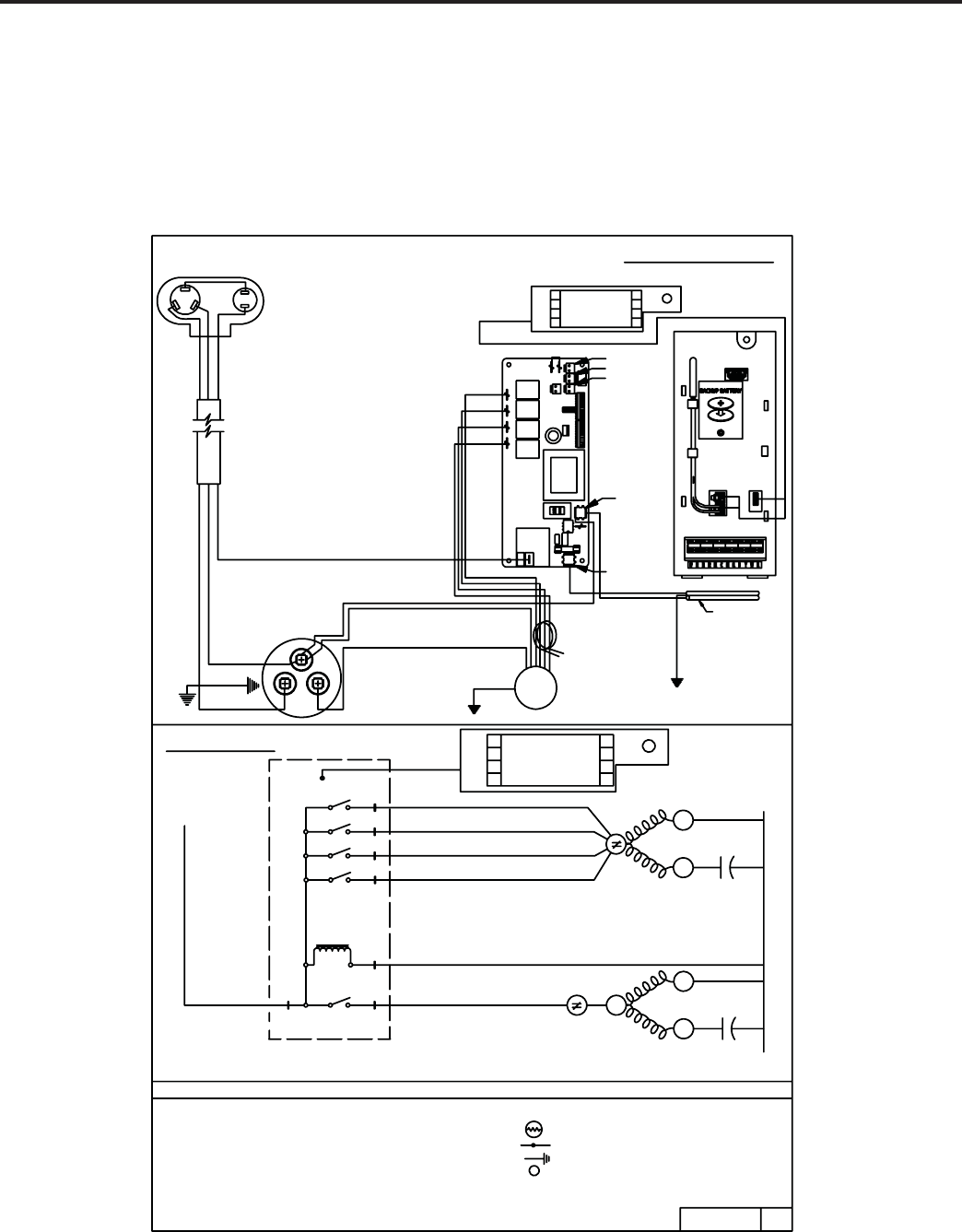
69
KUHL
ELECTRONIC CONTROL
COOL ONLY MODELS
SS08M10A, SS10M10A, SS12M10A, SS14M10A
SS12M30A, SS15M30A
SM18M30A, SM21M30A, SM24M30A
HIGH
MAX
MEDIUM
R
S
R
S
C
COMPRESSOR
ELECTRONIC CONTROL
L1 F4
F3
F1
NEUTRAL (115 V)
92170000
COMP
L1
L2 OR N
4
3
1
5
BLACK
LOW
F2
2
OLP
BLACK
COMPRESSOR
BLUE
RED
S
R
C
BLACK
CAPACITOR
BRACKET
RED
BLUE
TO CHASSIS
GREEN
HERM
FAN
COM
CAPACITOR
BRACKET
TO CAPACITOR
SUPPLY CORD
GREEN
ORGREEN/YELLOW
WHITE
MOTOR
BROWN
WHITE
WHITE
BLACK
GREEN
TO INNERWALL/
MOTOR MOUNT
BLUE
ORANGE
RED
UI HOLDER ELECTRONICS ASY
WIRING DIAGRAM
- HEATER ELEMENT
- INSULATOR
- GROUNDED LEAD SYMBOL
- COMBINATION TERMINAL
- THERMISTER
T
HTR
CAP
COMPR
UI
OLP
HL
TF
- HEATER LIMIT FUSE
- USER INTERFACE
- OVERLOAD PROTECTOR
- FAN MOTOR
- THERMAL FUSE
- COMPRESSOR
- CAPACITOR
MTR
L E G E N D
USERINTERFACE
SCHEMATIC
(230/208 V)
L2
OLP
OLP
COMPRESSOR
HERM COM
CAP
FAN MTR
FAN COM
CAP
PART NO. REV.
04
DCHRG
AIR
SENSOR
AMBIENT
AIR SENSOR
TO
DISPLAY
L1
L2 or ACN
ID COIL SENSOR
OD COIL SENSOR
OD AIR SENSOR
COMP
RELAY
F1
RELAY
F2
RELAY
F3
RELAY
F4
RELAY
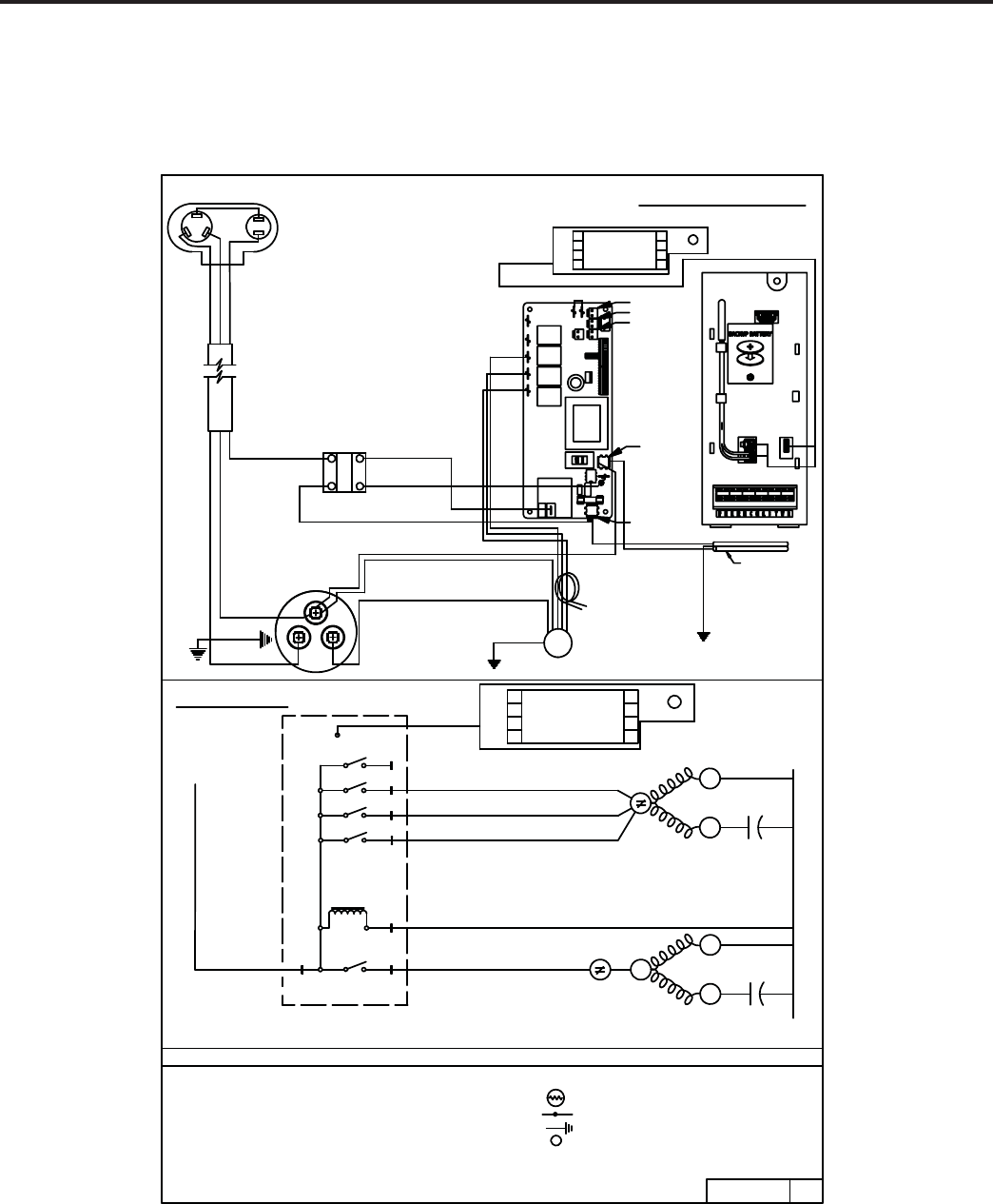
70
KUHL
ELECTRONIC CONTROL
COOL ONLY MODELS
SL28M30A, SL36M30A
WIRING DIAGRAM
SCHEMATIC
HIGH
MEDIUM
R
S
R
S
C
COMPRESSOR
C
S
R
FAN
COM
HERM
ELECTRONIC CONTROL
L1
F3
F1
NEUTRAL
OLP FAN MTR
CAP
FAN COM
OLP
COMPRESSOR
HERM
CAP
COM
(230/208 V)
L2
(115 V)
92170001
COMP
L1
USERINTERFACE
GREEN
TO CHASSIS
CAPACITOR
BLUE
BRACKET
RED
CAPACITOR
BLACK
RED
BLUE
BLACK
COMPRESSOR
L2 OR N
4
3
1
5
OLP
WHITE
BLACK
RED
BLUE
UI HOLDER ELECTRONICS ASY
WHITE
BROWN
MOTOR
WHITE
GREEN
TO INNERWALL/
MOTOR MOUNT
ORGREEN/YELLOW
GREEN
SUPPLY CORD
BRACKET
TO CAPACITOR
BLACK
LOW
F2
2
SSR
2
1
4
3
WHITE
BLUE
SOLID STATE RELAY
BLACK
04
REV.PART NO.
L E G E N D
- USER INTERFACE
- CAPACITOR
MTR
- COMPRESSOR
- THERMAL FUSE
- FAN MOTOR
- OVERLOAD PROTECTOR
OLP
UI
HL
TF
- HEATER LIMIT FUSE
- COMBINATION TERMINAL
- GROUNDED LEAD SYMBOL
- INSULATOR
- HEATER ELEMENT
T- THERMISTER
HTR
COMPR
CAP
L2 or ACN
L1
ID COIL SENSOR
OD COIL SENSOR
OD AIR SENSOR
F4
RELAY
F3
RELAY
COMP
RELAY
AMBIENT
AIR SENSOR
DCHRG
AIR
SENSOR
TO
DISPLAY
F2
RELAY
F1
RELAY
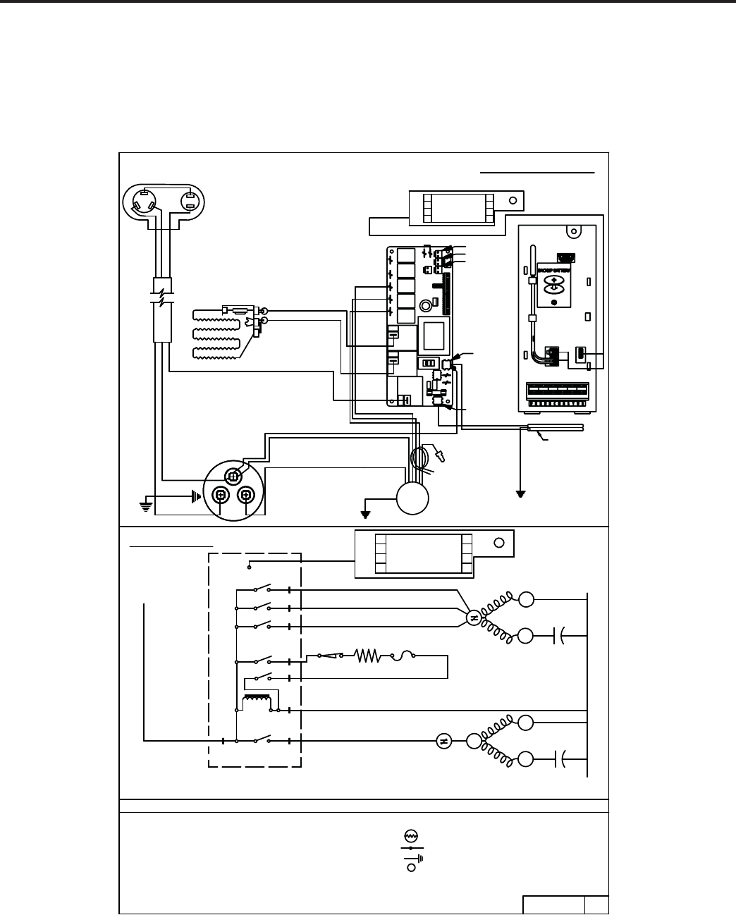
71
KUHL+
ELECTRONIC CONTROL
COOL WITH ELECTRIC HEAT MODELS
ES12M33A, ES15M33A
EM18M34A, EM24M34A
BLACK
ORANGE
UI HOLDER ELECTRONICS ASY
BLACK
BLUE
HEATER
BLACK
COMPRESSOR
S
OLP
R
C
BLUE
RED
BLACK
RED
BRACKET
CAPACITOR
BLUE
TO CHASSIS
GREEN
ORGREEN/YELLOW
BRACKET
TO CAPACITOR
GREEN
SUPPLY CORD
USERINTERFACE
OLP FAN MTR
MOTOR MOUNT
TO INNERWALL/
GREEN
BROWN
WHITE
CAPACITOR
COM
WHITE
MOTOR
FAN COM
L2
WHITE
RED
ORANGE
L1
F1
F2
F3
ELECTRIC HEAT
HIGH
ELECTRIC HEAT
MEDIUM
SCHEMATIC
1
2
3
7
L2 OR N
EH2
COMP
ELECTRONIC CONTROL
6
EH1 HTR TF
COMPRESSOR
OLP
HL
S
R
CAP
COMPRESSOR
HERM COM
CAP
LOW
(230/208 V)
C
S
R
04
PART NO. REV.
92170002
5
L1
HERM
FAN
WIRING DIAGRAM
RED
T- THERMISTER
- INSULATOR
HTR - HEATER ELEMENT
- GROUNDED LEAD SYMBOL
CAP
- COMBINATION TERMINAL
COMPR - COMPRESSOR
MTR
- CAPACITOR
- USER INTERFACEUI
- OVERLOAD PROTECTOR
OLP
TF
HL
- FAN MOTOR
- THERMAL FUSE
L E G E N D
- HEATER LIMIT FUSE
RV
RELAY
FAN 4
RELAY
FAN 3
RELAY
FAN 2
RELAY
FAN 1
RELAY
HEAT
RELAY
HEAT
RELAY
COMP
RELAY
OD AIR SENSOR
OD COIL SENSOR
ID COIL SENSOR
L2 or ACN
L1
DCHRG
AIR
SENSOR
TO
DISPLAY
AMBIENT
AIR SENSOR
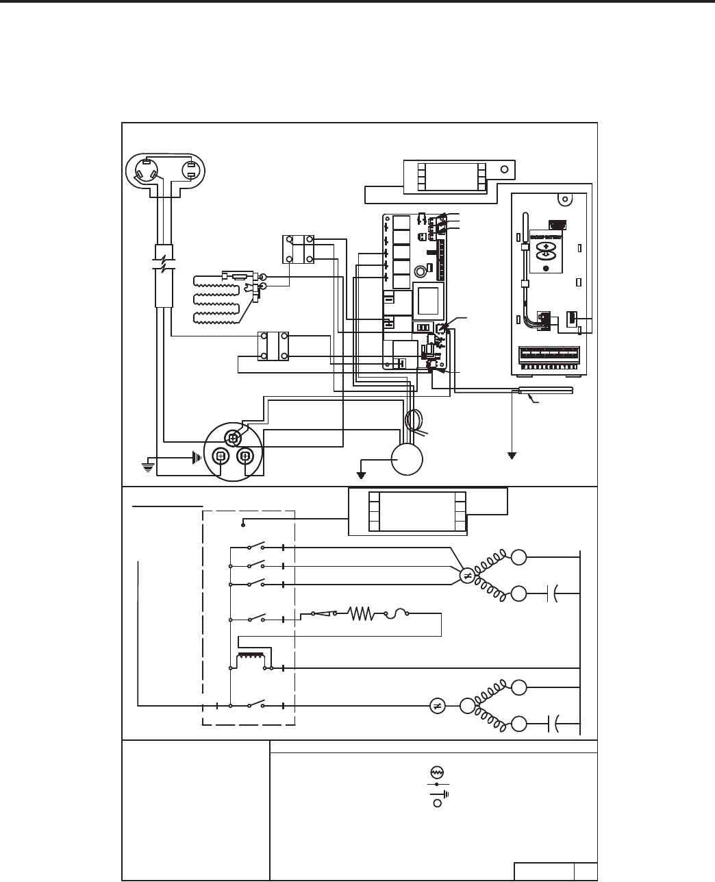
72
KUHL+
ELECTRONIC CONTROL
COOL WITH ELECTRIC HEAT MODEL
EL36M35A
L2
HIGH
F1
F2
1
R
S
L2 (230/208 V)
NE UTR AL
COMP
ELECTRIC HEAT
C
EH1
ME DIU M
LOW
ELECTRIC HEAT
F3
COMPRESSOR
3
2
5
6
S
R
L1
L1
(115 V)
WIRING DIAGRAM
UI HOLDER ELECTRONICS ASY
BLACK
BLUE
RED
RED
ORANGE
HE ATER
BLACK
RED
BLUE
COMPRESSOR
BLACK
SOLID STATE RELAY
WHITE
BLUE
BLACK
CAPACITOR
COM
HERM
FAN
RED
CAPACITOR
BRACKET
TO CHASSIS
BLUE
GREEN
MOT OR MOUNT
TO INNER WALL/
GREEN
BROWN
WHITE WHITE
WHITE
BLACK
GREEN
OR GREEN/YELLOW
TO CAPACITOR
BRACKET
SUPPLY CORD
S
C
R
OLP
SSR
SCHEMATIC
USER INTERFACE
FAN MTR
FAN COM
CAP
COMPRESSOR
HERM COM
CAP
OLP
HL TF
HTR
- C AP AC ITOR - THE R MIS T E R
T
HL
TF
UI
OLP
- FAN MOTOR
CAP
MTR
C OMPR - C OMP R E S S OR
- HE AT E R LIMIT FUS E
- THE R MAL F USE
- US E R INTE R FAC E
- OV E R LOAD PR OT E C T OR
- HEATER ELEMENT
- INS ULAT O R
- COMBINATION TER MINAL
- GR OUNDED LEAD SYMBOL
HTR
L E G E N D
00
REV.
PART NO.
92170007
MOTOR
SOLID STATE RELAY
SSR
RED
BLUE
BLACK
L2 or ACN
L1
IN DOO R CO IL S E NS OR
OUTDOOR COIL SENS OR
OUTDOOR AIR SE NS OR
RV
RELAY
FAN 4
RELAY
FAN 3
RELAY
FAN 2
RELAY
FAN 1
RELAY
HEAT
RELAY
HE AT
RELAY
COMP
RELAY
AMBIENT
AIR S E NS OR
DS C HR G
AIR
SENSOR
TO
DIS P LAY
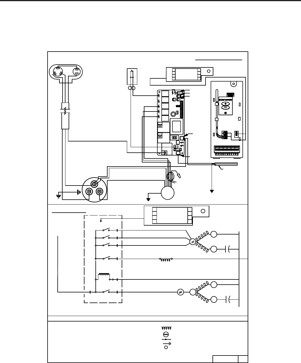
73
KUHL+
ELECTRONIC CONTROL
HEAT PUMP ONLY MODEL
YS10M10A
SCHEMATIC
MEDIUM
HIGH
LOW
R
S
R
S
C
COMPRESSOR
ELECTRONIC CONTROL
L1 F3
F2
F1
NEUTRAL
(230/208 V)
L2
(115 V)
92170003
COMP
L1
USERINTERFACE
HP
L2 OR N
3
2
1
6
5
REVERSE CYCLE RV
FAN
RED
BLACK
ORANGE
BLACK
HERM
WIRING DIAGRAM
WHITE SUPPLY CORD
TO CAPACITOR
BRACKET
WHITE WHITE
GREEN
ORGREEN/YELLOW
MOTOR
BROWN
TO INNERWALL/
MOTOR MOUNT
GREEN
TO CHASSIS
BLUE
BRACKET
CAPACITOR
RED
COM
CAPACITOR
GREEN
BLACK
OLP
S
BLACK
RED
BLUE
COMPRESSOR
R
C
UI HOLDER ELECTRONICS ASY
BLUE
BLUE
COIL, SOLENOID
BLACK
CAP
COM
HERM
COMPRESSOR
OLP
CAP
COM
FAN
FAN MTR
OLP
04
REV.PART NO.
L E G E N D
- CAPACITOR
CAP
- HEATER LIMIT FUSE
- THERMAL FUSE
- USER INTERFACE
- FAN MOTOR
- COMPRESSOR
- OVERLOAD PROTECTOR
COMPR
OLP
MTR
HL
TF
UI
T
- COMBINATION TERMINAL
- THERMISTER
- GROUNDED LEAD SYMBOL
HTR - HEATER ELEMENT
- INSULATOR
- REVERSING VALVE
HEAT
RELAY
HEAT
RELAY
COMP
RELAY
OD AIR SENSOR
OD COIL SENSOR
ID COIL SENSOR
L2 or ACN
L1
AMBIENT
AIR SENSOR
DCHRG
AIR
SENSOR
TO
DISPLAY
RV
RELAY
F4
RELAY
F3
RELAY
F2
RELAY
F1
RELAY
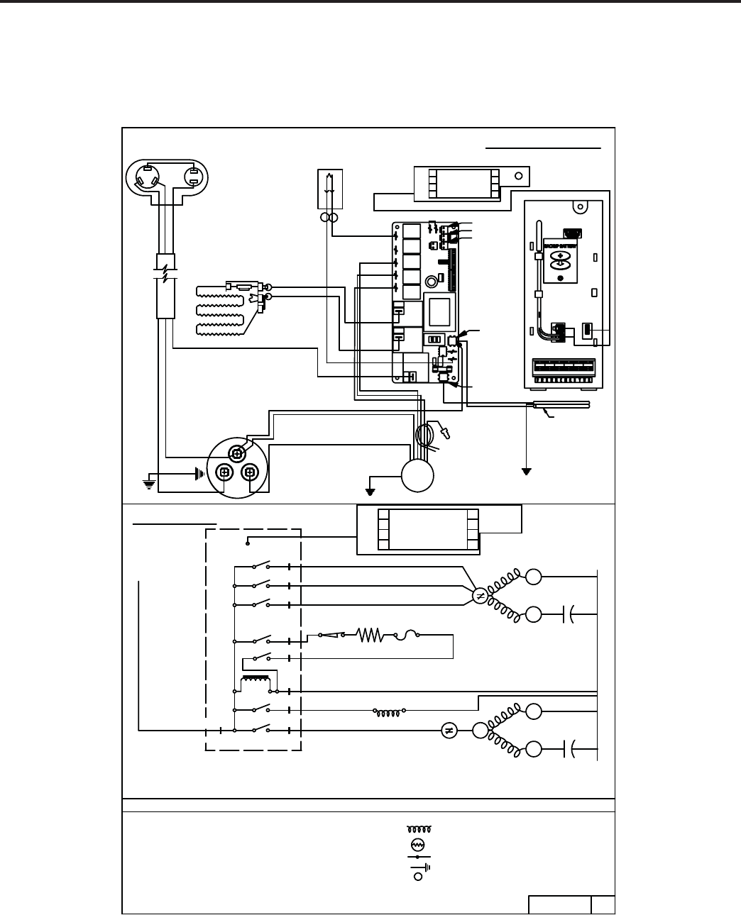
74
KUHL+
ELECTRONIC CONTROL
HEAT PUMP WITH ELECTRIC HEAT MODELS
YS12M33A, YM18M34A
SCHEMATIC
92170004
ELECTRIC HEAT
ELECTRIC HEAT
COMPRESSOR
MEDIUM
HIGH
LOW
R
S
REVERSING CYCLE R
S
C
ELECTRONIC CONTROL
EH1
2
3
L1
L1 F3
TF
F2
F1
HTR
EH2
1
6
7
5
USERINTERFACE
COMP
HL
RV
8
L2
R
COMPRESSOR
BLACK
S
OLP
BLUE
RED
C
BLACK
COIL, SOLENOID
BLUE
UI HOLDER ELECTRONICS ASY
BLUE
BROWN
MOTOR
BLACK
ORANGE
BLACK
CAPACITOR
GREEN
TO CHASSIS
WHITE
BRACKET
MOTOR MOUNT
TO INNERWALL/
GREEN
CAPACITOR
COM
HERM
RED
BLUE
RED
BRACKET
WHITE
GREEN
WHITE
ORGREEN/YELLOW
TO CAPACITOR
SUPPLY CORD
FAN
BLACK
WIRING DIAGRAM
RED
ORANGE
HEATER
(230/208 V)
L2
NEUTRAL (115 V)
CAP
COM
HERM
COMPRESSOR
OLP
RV
OLP FAN MTR
FAN COM
CAP
04
REV.PART NO.
L E G E N D
- OVERLOAD PROTECTOR
- COMPRESSOR
OLP
COMPR
MTR - FAN MOTOR
UI
TF
- USER INTERFACE
- THERMAL FUSE
CAP - CAPACITOR
- HEATER LIMIT FUSE
HL
- REVERSING VALVE
- INSULATOR
- HEATER ELEMENTHTR
- THERMISTER
- GROUNDED LEAD SYMBOL
- COMBINATION TERMINAL
T
RV
RELAY
FAN 4
RELAY
FAN 3
RELAY
FAN 2
RELAY
FAN 1
RELAY
HEAT
RELAY
HEAT
RELAY
COMP
RELAY
L1
L2 or ACN
ID COIL SENSOR
OD COIL SENSOR
OD AIR SENSOR
AMBIENT
AIR SENSOR
DCHRG
AIR
SENSOR
TO
DISPLAY
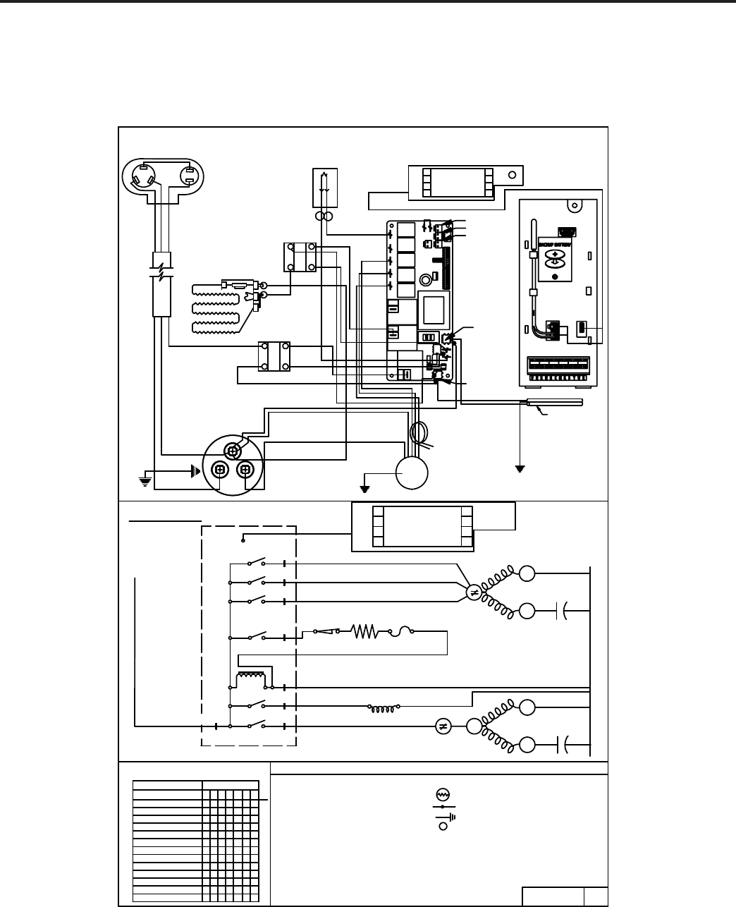
75
KUHL+
ELECTRONIC CONTROL
HEAT PUMP WITH ELECTRIC HEAT MODEL
YL24M35A
2
1
4
3
X
X
X
O
X
O
OO
X
O
O
OXXOO
O
O
OOO
O
O
OOO
O
OO
XX
O
HI FAN OOXOOO
OOOOX
MED FAN
LOW FAN OX
O
O
O
OXOO
HI HEAT (HP)
OO
MED HEAT (HP)
LOW HEAT (HP) XO
O
0X
OFF
HI COOL
MED COOL
SWITCH POSITION
X
X
HI HEAT (EH)
MED HEAT (EH)
LOW HEAT (EH)
X
O
O
O
O
654
CIRCUIT
O
OX
XO
OO
XOOO
X
X
O
OOOO
O
O
12
X
O
7
LOW COOL
3
L2
HIGH
F1
F2
7
1
R
S
L2 (230/208 V)
NEUTRAL
RV
COMP
RV
ELECTRIC HEAT
C
EH1
MEDIUM
LOW
ELECTRIC HEAT
F3
COMPRESSOR
3
2
REVERSING CYCLE
5
6
S
R
L1
L1
ELECTRONIC CONTROL
(115 V)
WIRING DIAGRAM
UI HOLDER ELECTRONICS ASY
BLACK
BLUE
RED
RED
ORANGE
HEATER
BLACK
RED
BLUE
COMPRESSOR
BLACK
SOLID STATE RELAY
WHITE
YELLOW
BLACK
CAPACITOR
COM
HERM
FAN
RED
CAPACITOR
BRACKET
TO CHASSIS
BLUE
GREEN
MOTOR MOUNT
TO INNERWALL/
GREEN
BROWN
WHITE WHITE WHITE
BLACK
GREEN
ORGREEN/YELLOW
TO CAPACITOR
BRACKET
SUPPLY CORD
S
C
R
OLP
SSR
SCHEMATIC
USERINTERFACE
FAN MTR
FAN COM
CAP
COMPRESSOR
HERM COM
CAP
OLP
HL TF
HTR
- CAPACITOR - THERMISTER
T
HL
TF
UI
OLP
- FAN MOTOR
CAP
MTR
COMPR - COMPRESSOR
- HEATER LIMIT FUSE
- THERMAL FUSE
- USER INTERFACE
- OVERLOAD PROTECTOR
- HEATER ELEMENT
- INSULATOR
- COMBINATION TERMINAL
- GROUNDED LEAD SYMBOL
HTR
L E G E N D
O = OPEN
X = CLOSED
SWITCH LOGIC
00
REV.
PART NO.
92170008
MOTOR
SOLID STATE RELAY
2
13
4
SSR
RED
BLUE
BLACK
O
O
O
L2 or ACN
L1
INDOOR COIL SENSOR
OUTDOOR COIL SENSOR
OUTDOOR AIR SENSOR
RV
RELAY
FAN 4
RELAY
FAN 3
RELAY
FAN 2
RELAY
FAN 1
RELAY
HEAT
RELAY
HEAT
RELAY
COMP
RELAY
AMBIENT
AIR SENSOR
DSCHRG
AIR
SENSOR
TO
DISPLAY
76
THERMISTORS’ RESISTANCE VALUES
(This Table Applies to All Thermistors)
TEMP
INDOOR AIR SENSOR
RESISTENCE (K Ohms)
RESISTANCE
TOLERANCE %
F MIN CENTR MAX MIN MAX
-25 210.889 225.548 240.224 6.50 6.51
-20 178.952 190.889 202.825 6.25 6.25
-15 151.591 161.325 171.059 6.03 6.03
-10 128.434 136.363 144.292 5.81 5.81
-5 108.886 115.340 121.794 5.60 5.60
0 92.411 97.662 102.912 5.38 5.38
5 78.541 82.812 87.083 5.16 5.16
10 66.866 70.339 73.812 4.94 4.94
15 57.039 59.864 62.688 4.72 4.72
20 48.763 51.060 53.357 4.50 4.50
25 41.786 43.654 45.523 4.28 4.28
30 35.896 37.415 38.934 4.06 4.06
31 34.832 36.290 37.747 4.02 4.02
32 33.803 35.202 36.601 3.97 3.97
33 32.808 34.150 35.492 3.93 3.93
34 31.846 33.133 34.421 3.89 3.89
35 30.916 32.151 33.386 3.84 3.84
36 30.016 31.200 32.385 3.80 3.80
37 29.144 30.281 31.418 3.75 3.75
38 28.319 29.425 30.534 3.76 3.77
39 27.486 28.532 29.579 3.67 3.67
40 26.697 27.701 28.704 3.62 3.62
45 23.116 23.931 24.745 3.40 3.40
50 20.071 20.731 21.391 3.18 3.18
55 17.474 18.008 18.542 2.96 2.96
60 15.253 15.684 16.115 2.75 2.75
65 13.351 13.697 14.043 2.53 2.53
66 13.004 13.335 13.666 2.48 2.48
67 12.668 12.984 13.301 2.44 2.44
68 12.341 12.644 12.947 2.39 2.39
69 12.024 12.313 12.603 2.35 2.35
70 11.716 11.993 12.269 2.31 2.31
71 11.418 11.682 11.946 2.26 2.26
72 11.128 11.380 11.633 2.22 2.22
73 10.846 11.088 11.329 2.18 2.18
74 10.574 10.804 11.034 2.13 2.13
75 10.308 10.528 10.748 2.09 2.09
76 10.051 10.260 10.469 2.04 2.04
77 9.800 10.000 10.200 2.00 2.00
78 9.550 9.748 9.945 2.03 2.03
79 9.306 9.503 9.699 2.07 2.07
80 9.070 9.265 9.459 2.10 2.10
81 8.841 9.033 9.226 2.13 2.13
82 8.618 8.809 9.000 2.17 2.17
83 8.402 8.591 8.780 2.20 2.20
84 8.192 8.379 8.566 2.23 2.23
85 7.987 8.172 8.358 2.27 2.27
86 7.789 7.972 8.155 2.30 2.30
87 7.596 7.778 7.959 2.33 2.33
88 7.409 7.589 7.768 2.37 2.37
89 7.227 7.405 7.583 2.40 2.40
90 7.050 7.226 7.402 2.43 2.43
91 6.878 7.052 7.226 2.47 2.47
92 6.711 6.883 7.055 2.50 2.50
93 6.548 6.718 6.889 2.53 2.53
94 6.390 6.558 6.727 2.57 2.57
95 6.237 6.403 6.569 2.60 2.60
96 6.087 6.252 6.417 2.63 2.63
97 5.942 6.105 6.268 2.67 2.67
98 5.800 5.961 6.122 2.70 2.70
99 5.663 5.822 5.981 2.73 2.73
100 5.529 5.686 5.844 2.77 2.77
105 4.912 5.060 5.208 2.93 2.93
110 4.371 4.511 4.651 3.10 3.10
115 3.898 4.030 4.161 3.27 3.27
120 3.482 3.606 3.730 3.43 3.43
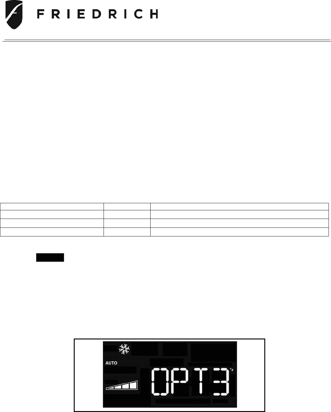
77
Replacement Remote Control Configuration Instructions
For Use with Kühl (cool only models) and Kühl + (cool & heat models)
Contents:
• Remote Control with Holder
• (2) AAA-batteries
• Instruction Sheet
ATTENTION! – You May Need to Configure The Replacement Remote Control
Please read instructions completely before attempting configuration of the Remote Control. Failure to
do so could result in the Remote Control not being able to operate the Air Conditioning Unit properly.
Step 1. A. Locate the Model # of your Air Conditioner.
B. Identify the prefix (First 2 Letters) of your unit’s model #.
C. Look at the chart below and in it, find the prefix of your AC unit’s model #.
D. Note the Option # Code (OPT#) next to it and the required action. The unit’s
display is supposed to show this OPT# Code.
Model Prefix Option Code Required Action
SS, SM OPT 1 None –
Remote Control configured for use with air conditioner
SL OPT 2 Perform Steps 2 - 5
YS, YM, YL, ES, EM, EL OPT 3 Perform Steps 2 - 5
Step 2. Point the Remote Control at Air Conditioning Unit and then press the Remote Control’s
POWER
Key once to illuminate the Air Conditioning Unit’s display.
Step 3. Once the display on the Air Conditioning Unit is illuminated, check the Option Code
number (OPT#) shown in the display and ensure it matches the OPT# code for your unit
as per the chart above.
Air Conditioner Unit’s Display
(see example below Fig 1)
OPT1
OPT2
OPT3 Displayed example
Fi
g
ure 1
Kühl Remote Control
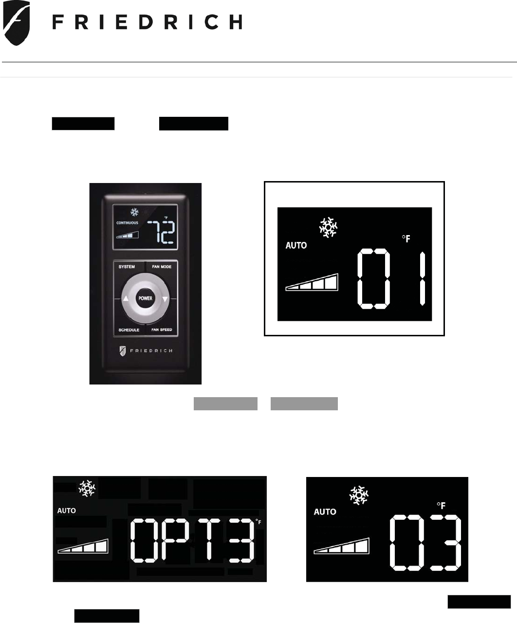
78
Kühl Remote Control
Step 4 Checking the Remote Control’s OPT # Code
With the Remote Control’s display illuminated, press and hold the Remote Control’s
SCHEDULE and the FAN SPEED Keys simultaneously for approximately 6 seconds until
the Remote Control displays its current OPT# Code.
If the OPT# Code is different than the AC Unit’s OPT# Code see instructions below:
Remote Control Remote Control’s OPT# Code
(see example below Fig 2)
Using the Remote Control’s S Increase
or d Decrease Keys, change the OPT# Code
displayed on the Remote Control to match the OPT # Code shown on the Air
Conditioning Unit’s display
(see examples below)
.
Air Conditioning Unit Display Remote Control Display
Step 5. To save the setting in the Remote Control, press and hold the Remote Control SCHEDULE
and FAN SPEED Key simultaneously for approximately 6 seconds until the displayed
configuration number on the Remote Control flashes.
The Remote Control is now configured to work with the air conditioner.
Figure 2
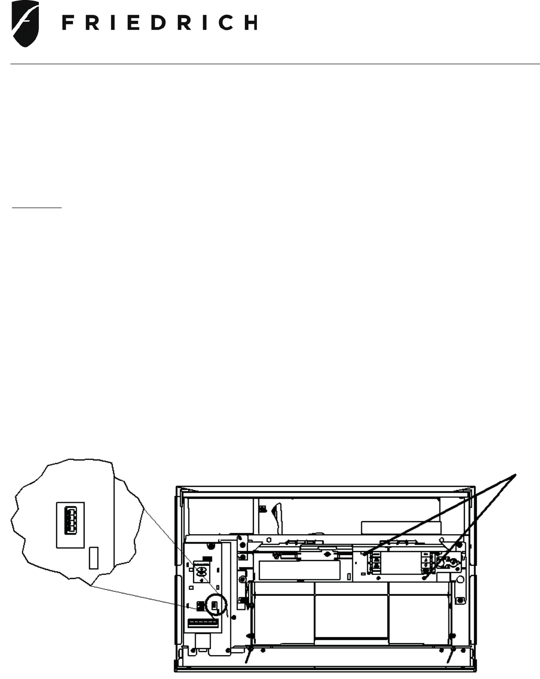
79
Kühl User Interface Service Kit
Replacement Instructions
For Use with Kühl (cool only models) and Kühl + (cool and heat models)
ATTENTION! - Please read these instructions completely before attempting replacement.
Always unplug the power supply from the power supply receptacle.
Contents:
• User Interface (UI)
• Ribbon Cable
• 2 – Mounting screws for UI
• Instruction Sheet
Step 1. Disconnect ribbon cable by pulling straight out
Step 2. Remove 2 –mounting screws securing UI and disconnect ribbon cable
Step 3. Remove UI and ribbon cable from handle assembly
Step 4. Install new UI using the 2-screws, route new ribbon cable and reattach ribbon cable to UI
and Main control board
Step 5. Verify control operation
Mounting screws
Ribbon cable connection
80
INSTRUCTIONS FOR USING COOLING LOAD ESTIMATE
FORM FOR ROOM AIR CONDITIONERS
(AHAM PUB. NO. RAC-1)
A. This cooling load estimate form is suitable for estimating the cooling load for comfort air conditioning installations
which do not require specifi c conditions of inside temperature and humidity.
B. The form is based on an outside design temperature of 95°F dry bulb and 75°F wet bulb. It can be used for areas
in the continental United States having other outside design temperatures by applying a correction factor for the
particular locality as determined from the map.
C. The form includes “day” factors for calculating cooling loads in rooms where daytime comfort is desired (such as
living rooms, offi ces, etc.)
D. The numbers of the following paragraphs refer to the corresponding numbered item on the form:
1. Multiply the square feet of window area for each exposure by the applicable factor. The window area is the
area of the wall opening in which the window is installed. For windows shaded by inside shades or venetian
blinds, use the factor for “Inside Shades.” For windows shaded by outside awnings or by both outside aw-
nings and inside shades (or venetian blinds), use the factor for “Outside Awnings.” “Single Glass” includes
all types of single thickness windows, and “Double Glass” includes sealed airspace types, storm windows,
and glass block. Only one number should be entered in the right hand column for Item 1, and this number
should represent only the exposure with the largest load.
2. Multiply the total square feet of all windows in the room by the applicable factor.
3a. Multiply the total length (linear feet) of all walls exposed to the outside by the applicable factor. Doors should
be considered as being part of the wall. Outside walls facing due north should be calculated separately from
outside walls facing other directions. Walls which are permanently shaded by adjacent structures should be
considered “North Exposure.” Do not consider trees and shrubbery as providing permanent shading. An
uninsulated frame wall or a masonry wall 8 inches or less in thickness is considered “Light Construction.” An
insulated wall or masonry wall over 8 inches in thickness is considered “Heavy Construction.”
3b. Multiply the total length (linear feet) of all inside walls between the space to be conditioned and any uncondi-
tioned spaces by the given factor. Do not include inside walls which separate other air conditioned rooms.
4. Multiply the total square feet of roof or ceiling area by the factor given for the type of construction most nearly
describing the particular application (use one line only.)
5. Multiply the total square feet of fl oor area by the factor given. Disregard this item if the fl oor is directly on the
ground or over a basement.
6. Multiply the number of people who normally occupy the space to be air conditioned by the factor given. Use
a minimum of 2 people.
7. Determine the total number of watts for light and electrical equipment, except the air conditioner itself, that
will be in use when the room air conditioning is operating. Multiply the total wattage by the factor given.
8. Multiply the total width (linear feet) of any doors or arches which are continually open to an unconditioned
space by the applicable factor.
NOTE: Where the width of the doors or arches is more than 5 feet, the actual load may exceed the calculated
value. In such cases, both adjoining rooms should be considered as a single large room, and the room air
conditioner unit or units should be selected according to a calculation made on this new basis.
9. Total the loads estimated for the foregoing 8 items.
10. Multiply the subtotal obtained in item 9 by the proper correction factor, selected from the map, for the particular
locality. The result is the total estimated design cooling load in BTU per hour.
E. For best results, a room air conditioner unit or units having a cooling capacity rating (determined in accordance
with the NEMA Standards Publication for Room Air Conditioners, CN 1-1960) as close as possible to the estimated
load should be selected. In general, a greatly oversized unit which would operate intermittently will be much less
satisfactory than one which is slightly undersized and which would operate more nearly continuously.
F. Intermittent loads such as kitchen and laundry equipment are not included in this form.
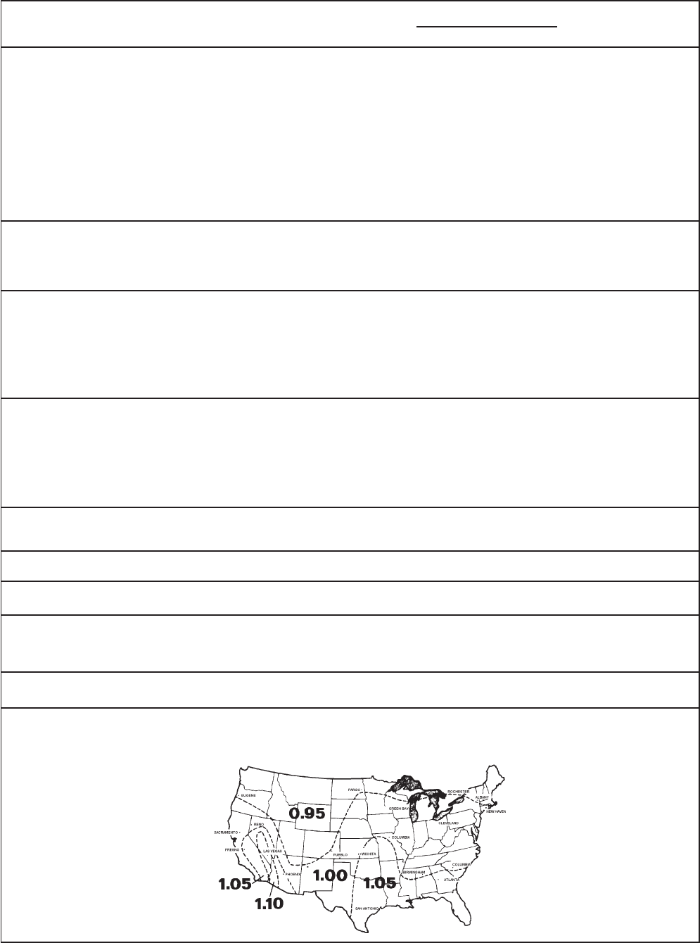
81
COOLING LOAD ESTIMATE FORM
HEAT GAIN FROM
1. WINDOWS: Heat gain from the sun.
Northeast
East
Southeast
South
Southwest
West
Northwest
North
2. WINDOWS: Heat by conduction
(Total of all windows.)
Single glass
Double glass or glass block
3. WALLS: (Based on linear feet of wall)
a. Outside walls
North Exposure
Other than North exposure
b. Inside Walls (between conditioned and
unconditioned spaces only.)
4. ROOF OR CEILING: (Use one only)
a. Roof, uninsulated
b. Roof, 1 inch or more insulation
c. Ceiling, occupied space above
d. Ceiling, insulated, with attic space above
e. Ceiling, uninsulated, with attic space above
5. Floor: (Disregard if fl oor is directly on ground or
over a basement.
6. NUMBER OF PEOPLE
7. LIGHTS AND ELECTRICAL EQUIPMENT IN USE
8. DOORS AND ARCHES CONTINUOUSLY
OPENED TO UNCONDITIONED SPACE: (TOTAL
LINEAR FEET OF WIDTH.)
9. SUBTOTAL
10. TOTAL COOLING LOAD (BTU per hour to be used
for selection of room air conditioner(s).)
No
Shades*
60
80
75
75
110
150
120
0
___ _sq. ft.
___ _sq. ft.
____sq. ft.
____sq. ft.
____sq. ft.
____sq. ft.
____sq. ft.
____sq. ft.
____sq. ft.
____sq. ft.
____ ft.
____ ft.
____sq. ft.
____sq. ft.
____sq. ft.
____sq. ft.
____sq. ft.
____sq. ft.
____sq. ft.
____
____watts
____ft.
*****
Inside
Shades*
25
40
30
35
45
65
50
0
Outside
Awnings*
20 ____
25 ____
20 ____
20 ____
30 ____
45 ____
35 ____
0 ____
(Area
X Factor)
Use
only
the
largest
load.
Use
only
one.
____
____
____
____
____
____
____
____
QUANTITY BTU/Hr.
(Quantity x Factor)
14
7
30
19
8
3
5
12
3
600
3
300
*****
Light Construction
30
60
Heavy Construction
20
30
_____
_____
_____
_____
_____
_____
_____
_____
_____
_____
_____
_____
_____
_____
_____
* These factors are for single glass
only. For glass block, multiply the
above factors by 0.5; for double
glass or storm windows, multiply the
above factors by 0.8.
FACTORS
DAY
____ Total in Item 9 X ____ (Factor from Map) = ____
82
Following is an example using the heat load form:
A space to be conditioned is part of a house geographically
located in an area where the lowest outdoor ambient winter
temperature is 40°F. The calculated heat loss is 184 BTU/
Hr./°F.
Subtract 40°F (lowest outdoor ambient temperature for the
geographical location) from 70°F (inside design temperature
of the unit) for a difference of 30°F. Multiply 184 by 30 for a
5500 BTU/Hr. total heat loss for the calculated space.
On the graph, plot the base point (70°) and a point on the
40°F line where it intersects with the 5500 BTU/Hr. line on
the left scale. Draw a straight line from the base point 70
through the point plotted at 40°F. This is the total heat loss
line.
Knowing that we have a 5500 BTU/Hr. heat loss, and
we expect that our heat pump will maintain a 70°F inside
temperature at 40°F outdoor ambient, we plot the selected
unit capacity BTU/Hr. of the unit between 35° and 60° on the
graph and draw a straight line between these points. Where
the total heat loss line and the unit capacity line intersect,
read down to the outdoor ambient temperature scale and
fi nd that this unit will deliver the required BTU/Hr. capacity
to approximately 30°F.
The heat load form on the following page may be used by
servicing personnel to determine the heat loss of a conditioned
space and the ambient winter design temperatures in which
the unit will heat the calculated space.
The upper half of the form is for computing the heat loss of
the space to be conditioned. It is necessary only to insert
the proper measurements on the lines provided and multiply
by the given factors, then add this result for the total heat
loss in BTU/Hr./°F.
The BTU/Hr. per °F temperature difference is the 70°F
inside winter designed temperature minus the lowest outdoor
ambient winter temperature of the area where the unit is
installed. This temperature difference is used as the multiplier
when calculating the heat loss.
The graph shows the following:
Left Hand Scale Unit capacity BTU/Hr. or heat loss
BTU/Hr.
Bottom Scale Outdoor ambient temperature, base
point.
Heat Pump Model BTU/Hr. capacity heat pump will
deliver at outdoor temperatures.
Balance Point Maximum BTU/Hr. heat pump
will deliver at indicated ambient
temperature.
HEAT LOAD FORM
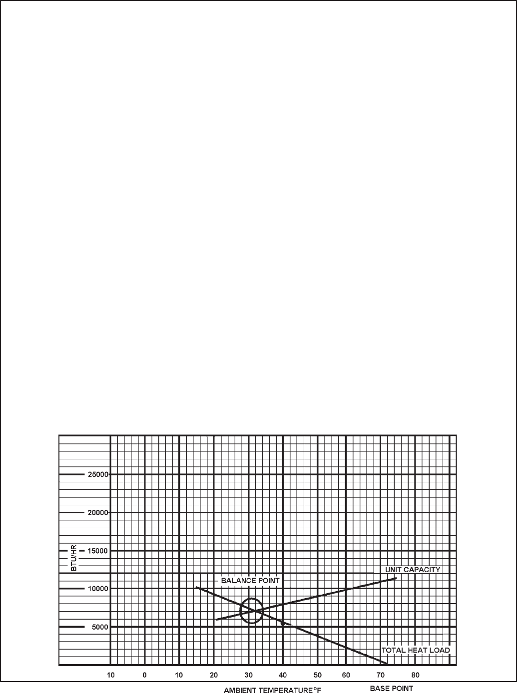
83
HEATING LOAD FORM
FRIEDRICH ROOM UNIT HEAT PUMPS
BTU/HR PER
WALLS: (Linear Feet) °F TEMP. DIFFERENCE
2” Insulation Lin. Ft. x 1.6
Average Lin. Ft. x 2.6
WINDOWS & DOORS (Area, sq. ft.)
Single Glass: Sq. Ft. x 1.13
Double Glass: Sq. Ft. x 0.61
INFILTRATION - WINDOWS & DOORS: AVG. Lin. Ft. x 1.0
Loose Lin. Ft. x 2.0
CEILING: (Area, Sq. Ft.)
Insulated (6”) Sq. Ft. x 0.07
Insulated (2”) Sq. Ft. x 0.10
Built-up Roof (2” insulated Sq. Ft. x 0.10
Built-up Roof (1/2” insulated) Sq. Ft. x 0.20
No Insulation Sq. Ft. x 0.33
FLOOR: (Area, Sq. Ft.)
Above Vented Crawl space
Insulated (1:) Sq. Ft. x 0.20
Uninsulated Sq. Ft. x 0.50
* Slab on Ground Lin. Ft. x 1.70
1” Perimeter insulation Lin. Ft. x 1.00
* Based on Linear Feet of outside wall TOTAL HEAT LOSS PER °F BTU/HR/°F
Multiply total BTU/HR/°F X 30 and plot on the graph below at 40°F. Draw a straight line from
the 70 base point thru the point plotted at 40°F. The intersection of this heat loss line with the
unit capacity line represents the winter design heating load.

84
Friedrich Air Conditioning Company
P.O. Box 1540
San Antonio, TX 78295
210.357.4400
www.friedrich.com
ROOM AIR CONDITIONERS
LIMITED WARRANTY
FIRST YEAR
ANY PART: If any part supplied by FRIEDRICH fails because of a defect in workmanship or material within twelve months from date of original
purchase, FRIEDRICH will repair the product at no charge, provided room air conditioner is reasonably accessible for service. Any additional
labor cost for removing inaccessible units and/or charges for mileage related to travel by a Service Agency that exceeds 25 miles one way will
be the responsibility of the owner. This remedy is expressly agreed to be the exclusive remedy within twelve months from the date of the original
purchase.
SECOND THROUGH FIFTH YEAR
SEALED REFRIGERANT SYSTEM: If the Sealed Refrigeration System (defi ned for this purpose as the compressor, condenser coil, evaporator
coil, reversing valve, check valve, capillary, fi lter drier, and all interconnecting tubing) supplied by FRIEDRICH in your Room Air Conditioner fails
because of a defect in workmanship or material within sixty months from date of purchase, FRIEDRICH will pay a labor allowance and parts
necessary to repair the Sealed Refrigeration System; PROVIDED FRIEDRICH will not pay the cost of diagnosis of the problem, removal, freight
charges, and transportation of the air conditioner to and from the Service Agency, and the reinstallation charges associated with repair of the
Sealed Refrigeration System. All such cost will be the sole responsibility of the owner. This remedy is expressly agreed to be the exclusive remedy
within sixty months from the date of the original purchase.
APPLICABILITY AND LIMITATIONS: This warranty is applicable only to units retained within the Fifty States of the U.S.A., District of Columbia,
and Canada. This warranty is not applicable to:
1. Air fi lters or fuses.
2. Products on which the model and serial numbers have been removed.
3. Products which have defects or damage which results from improper installation, wiring, electrical current characteristics, or
maintenance; or caused by accident, misuse or abuse, fi re, fl ood, alterations and/or misapplication of the product and/or units
installed in a corrosive atmosphere, default or delay in performance caused by war, government restrictions or restraints, strikes,
material shortages beyond the control of FRIEDRICH, or acts of God.
OBTAINING WARRANTY PERFORMANCE: Service will be provided by the FRIEDRICH Authorized Dealer or Service Organization in your
area. They are listed in the Yellow Pages. If assistance is required in obtaining warranty performance, write to: Room Air Conditioner Service
Manager, Friedrich Air Conditioning Co., P.O. Box 1540, San Antonio, TX 78295-1540.
LIMITATIONS: THIS WARRANTY IS GIVEN IN LIEU OF ALL OTHER WARRANTIES. Anything in the warranty notwithstanding, ANY
IMPLIED WARRANTIES OF FITNESS FOR PARTICULAR PURPOSE AND/OR MERCHANTABILITY SHALL BE LIMITED TO THE DURATION
OF THIS EXPRESS WARRANTY. MANUFACTURER EXPRESSLY DISCLAIMS AND EXCLUDES ANY LIABILITY FOR CONSEQUENTIAL
OR INCIDENTAL DAMAGE FOR BREACH OF ANY EXPRESSED OR IMPLIED WARRANTY.
Performance of Friedrich’s Warranty obligation is limited to one of the following methods:
1. Repair of the unit
2. A refund to the customer for the prorated value of the unit based upon the remaining warranty period of the unit.
Providing a replacement unit of equal value3.
The method of fulfi llment of the warranty obligation is at the sole discretion of Friedrich Air Conditioning.
NOTE: Some states do not allow limitations on how long an implied warranty lasts, or do not allow the limitation or exclusion of consequential or
incidental damages, so the foregoing exclusions and limitations may not apply to you.
OTHER: This warranty gives you specifi c legal rights, and you may also have other rights which vary from state to state.
PROOF OF PURCHASE: Owner must provide proof of purchase in order to receive any warranty related services.
All service calls for explaining the operation of this product will be the sole responsibility of the consumer.
All warranty service must be provided by an Authorized FRIEDRICH Service Agency, unless authorized by FRIEDRICH prior to repairs being
made.
(10 - 08)

FRIEDRICH AIR CONDITIONING CO.
Post Offi ce Box 1540 · San Antonio, Texas 78295-1540
4200 N. Pan Am Expressway · San Antonio, Texas 78218-5212
(210) 357-4400 · 877-599-5665 x 846 · FAX (210) 357-4490
Email: tac@friedrich.com
www.friedrich.com
Printed in the U.S.A.
TECHNICAL SUPPORT
CONTACT INFORMATION

Kuhl-ServMan (5-10)
FRIEDRICH AIR CONDITIONING CO.
Post Offi ce Box 1540 · San Antonio, Texas 78295-1540
4200 N. Pan Am Expressway · San Antonio, Texas 78218-5212
(210) 357-4400 · FAX (210) 357-4490
www.friedrich.com
Printed in the U.S.A.
