Friedrich Quietmaster 2009 Users Manual P2KPD 1 05
2009 to the manual 7fa0218b-0ba3-4860-ab72-ff19283e8bef
2015-02-02
: Friedrich Friedrich-Quietmaster-2009-Users-Manual-428495 friedrich-quietmaster-2009-users-manual-428495 friedrich pdf
Open the PDF directly: View PDF ![]() .
.
Page Count: 68

Service Manual
Room Air Conditioners
RAC-ServMan (04-09)
Models
2009
2008
Low
Cool
High
Cool
Low
Heat
High
Heat
MAX
COOL
MAX
HEAT
Fan
Only
O
ff
Allow 3 min. betweenrestarts
!
Money
Fan
TimerOp
eration
Set Hr.
Stop
Start
Temperature
Fan
Cool
On/O
Power
Cooler
Only SpeedSaver
®
Warmer
Money
Fan
Timer O
peration
Set Hr.
Stop
Start
Temperature
Fan
Cool
On/Off
Power
Cooler
Only SpeedSaver
®
Warmer

FRIEDRICH AIR CONDITIONING CO.
Post Ofce Box 1540 · San Antonio, Texas 78295-1540
4200 N. Pan Am Expressway · San Antonio, Texas 78218-5212
(210) 357-4400 · FAX (210) 357-4490
www.friedrich.com
Printed in the U.S.A.
TECHNICAL SUPPORT
CONTACT INFORMATION
1
Table Of Contents
Important Safety Information ........................................................................................................................................ 2-4
Introduction ...................................................................................................................................................................... 5
Unit Identication ............................................................................................................................................................. 6
Chassis Specications for 2009, 2008 Models ............................................................................................................... 7
Installation Information/Sleeve Dimensions .................................................................................................................... 8
Performance Data ........................................................................................................................................................... 9
Electrical Data ............................................................................................................................................................... 10
Before Operating the Unit .............................................................................................................................................. 11
How to Operate the QM Programmable ........................................................................................................................ 12
How to Use the QM Programmable Remote Control ..................................................................................................... 13
How to Operate the XQ .................................................................................................................................................. 14
How to Use the XQ Remote Control .............................................................................................................................. 15
How to Operate the QM and Twintemp .................................................................................................................... 16-17
Testing the Electronic Control and Error Code Listings .............................................................................................17-18
Testing the Rotary Control Switches ..........................................................................................................................19-20
Functional Component Denition ................................................................................................................................... 20
Components Testing ...................................................................................................................................................21-24
Defrost Thermostat Operation ........................................................................................................................................ 24
Electronic Control Sequence of Operation ..................................................................................................................... 25
Refrigeration Sequence of Operation ............................................................................................................................. 26
Sealed Refrigeration System Repairs ....................................................................................................................... 27-30
Hermetics Components Check ...................................................................................................................................... 31
Reversing Valve Description/Operation ......................................................................................................................... 32
Testing the Coil .............................................................................................................................................................. 33
Checking the Reversing Valve .................................................................................................................................. 33-34
Compressor Checks .................................................................................................................................................. 35-36
Compressor Replacement ......................................................................................................................................... 37-38
Routine Maintenance ................................................................................................................................................. 39-40
Troubleshooting ......................................................................................................................................................... 41-48
Wiring Diagrams ........................................................................................................................................................ 49-58
Instructions for using Cooling Load Estimate Form ........................................................................................................ 58
Cooling Load Estimate Form .......................................................................................................................................... 60
Heat Load Form ......................................................................................................................................................... 61-62
Warranty .......................................................................................................................................................................... 63
IMPORTANT SAFETY INFORMATION
The information contained in this manual is intended for use by a qualied service technician who is familiar
with the safety procedures required for installation and repair, and who is equipped with the proper tools and
test instruments required to service this product.
Installation or repairs made by unqualied persons can result in subjecting the unqualied person making
such repairs as well as the persons being served by the equipment to hazards resulting in injury or electrical
shock which can be serious or even fatal.
Safety warnings have been placed throughout this manual to alert you to potential hazards that may be
encountered. If you install or perform service on equipment, it is your responsibility to read and obey these
warnings to guard against any bodily injury or property damage which may result to you or others.
PERSONAL INJURY OR DEATH HAZARDS
ELECTRICAL HAZARDS:
Unplug and/or disconnect all electrical power to the unit before performing inspections, •
maintenance, or service.
Make sure to follow proper lockout/tag out procedures.•
Always work in the company of a qualied assistant if possible. •
Capacitors, even when disconnected from the electrical power source, retain an electrical charge •
potential capable of causing electric shock or electrocution.
Handle, discharge, and test capacitors according to safe, established, standards, and approved •
procedures.
Extreme care, proper judgment, and safety procedures must be exercised if it becomes necessary •
to test or troubleshoot equipment with the power on to the unit.
Your safety and the safety of others are very important.
We have provided many important safety messages in this manual and on your appliance. Always read
and obey all safety messages.
All safety messages will tell you what the potential hazard is, tell you how to reduce the chance of injury,
and tell you what will happen if the instructions are not followed.
This is a Safety Alert symbol.
This symbol alerts you to potential hazards that can kill or hurt you and others.
All safety messages will follow the safety alert symbol with the word “WARNING”
or “CAUTION”. These words mean:
You can be killed or seriously injured if you do not follow instructions.
You can receive minor or moderate injury if you do not follow instructions.
A message to alert you of potential property damage will have the
word “NOTICE”. Potential property damage can occur if instructions
are not followed.
WARNING
CAUTION
NOTICE
2
Do not spray or pour water on the return air grille, discharge air grille, evaporator coil, control panel, •
and sleeve on the room side of the air conditioning unit while cleaning.
Electrical component malfunction caused by water could result in electric shock or other electrically •
unsafe conditions when the power is restored and the unit is turned on, even after the exterior is dry.
Never operate the A/C unit with wet hands.•
Use air conditioner on a single dedicated circuit within the specied amperage rating. •
Use on a properly grounded outlet only.•
Do not remove ground prong of plug.•
Do not cut or modify the power supply cord.•
Do not use extension cords with the unit.•
Follow all safety precautions and use proper and adequate protective safety aids such as: gloves, •
goggles, clothing, adequately insulated tools, and testing equipment etc.
Failure to follow proper safety procedures and/or these warnings can result in serious injury or death. •
REFRIGERATION SYSTEM HAZARDS:
Use approved standard refrigerant recovering procedures and equipment to relieve pressure before •
opening system for repair.
Do not allow liquid refrigerant to contact skin. Direct contact with liquid refrigerant can result in minor •
to moderate injury.
Be extremely careful when using an oxy-acetylene torch. Direct contact with the torch’s ame or hot •
surfaces can cause serious burns.
Make sure to protect personal and surrounding property with re proof materials.•
Have a re extinguisher at hand while using a torch.•
Provide adequate ventilation to vent off toxic fumes, and work with a qualied assistant whenever •
possible.
Always use a pressure regulator when using dry nitrogen to test the sealed refrigeration system for •
leaks, ushing etc.
Make sure to follow all safety precautions and to use proper protective safety aids such as: gloves, •
safety glasses, clothing etc.
Failure to follow proper safety procedures and/or these warnings can result in serious injury or death. •
MECHANICAL HAZARDS:
Extreme care, proper judgment and all safety procedures must be followed when testing, •
troubleshooting, handling, or working around unit with moving and/or rotating parts.
Be careful when, handling and working around exposed edges and corners of sleeve, chassis, and •
other unit components especially the sharp ns of the indoor and outdoor coils.
Use proper and adequate protective aids such as: gloves, clothing, safety glasses etc.•
Failure to follow proper safety procedures and/or these warnings can result in serious injury or death.•
3

PROPERTY DAMAGE HAZARDS
FIRE DAMAGE HAZARDS:
Read the Installation/Operation Manual for this air conditioning unit prior to operating.•
Use air conditioner on a single dedicated circuit within the specied amperage rating. •
Connect to a properly grounded outlet only.•
Do not remove ground prong of plug.•
Do not cut or modify the power supply cord.•
Do not use extension cords with the unit.•
Failure to follow these instructions can result in re and minor to serious property damage.•
WATER DAMAGE HAZARDS:
Improper installation maintenance, or servicing of the air conditioner unit, or not following the above •
Safety Warnings can result in water damage to personal items or property.
Insure that the unit has a sufcient pitch to the outside to allow water to drain from the unit. •
Do not drill holes in the bottom of the drain pan or the underside of the unit. •
Failure to follow these instructions can result in result in damage to the unit and/or minor to serious •
property damage.
4
5
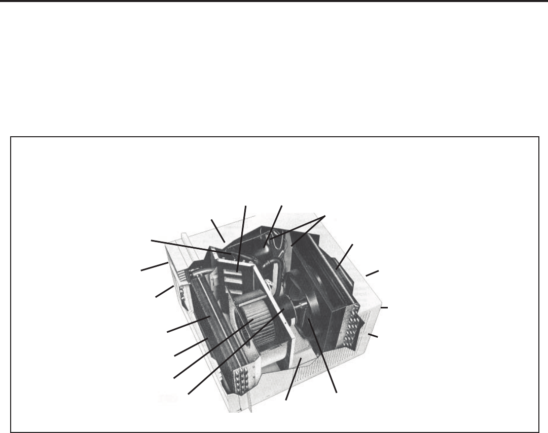
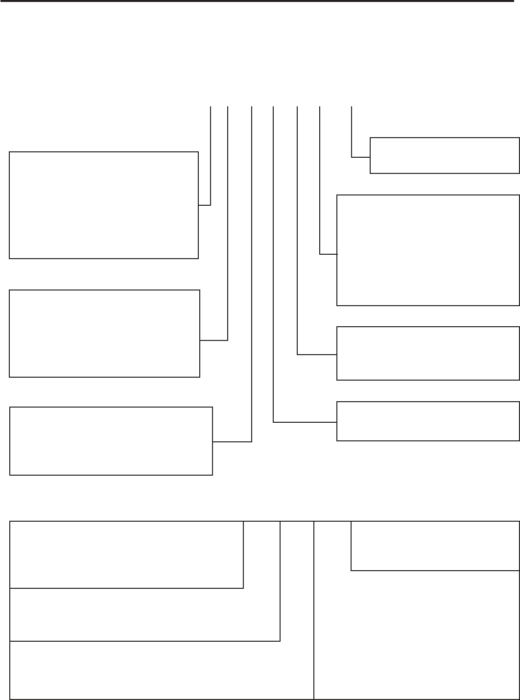
TYPICAL UNIT COMPONENTS
Fresh Air Compressor
Capillary Tube Liquid Filter Driers
Reversing Valve Condenser Coil
(some models)
Discharge Air
Front Cover
System Switches
Outdoor Grille
Evaporator Coil Sleeve
Return Air Grille/Filter
Blower Wheel
Blower Motor Condenser Fan Blade
Basepan
This service manual is designed to be used in conjunction with the installation manuals provided with each air conditioning
system component.
This service manual was written to assist the professional RAC service technician to quickly and accurately diagnose
and repair malfunctions.
This manual will deal with subjects in a general nature. (i.e. all text will not pertain to all models).
IMPORTANT: It will be necessary for you to accurately identify the unit you are servicing, so you can be certain of a
proper diagnosis and repair (See Unit Identication on page 6).
INTRODUCTION
6
Serial Number
Decade Manufactured
L=0 C=3 F=6 J=9
A=1 D=4 G=7
B=2 E=5 H=8
L H G R 00001
Production Run Number
Year Manufactured
A=1 D=4 G=7 K=0
B=2 E=5 H=8
C=3 F=6 J=9
Product Line
R = RAC
Month Manufactured
A=Jan D=Apr G=Jul K=Oct
B=Feb E=May H=Aug L=Nov
C=Mar F=Jun J=Sept M=Dec
1st Digit – Function
S = Straight Cool, Value Series
Y = Heat Pump
E = Electric Heat
K = Straight Cool
R = Straight Cool
X = Straight Cool
2nd Digit
Q = Q-Star
S = Small Chassis
M = Medium Chassis
L = Large Chassis
H = HazardGard
3rd and 4th Digit - Approximate
BTU/HR in 1000s (Cooling)
Heating BTU/Hr capacity listed in the
Specication/Performance Data Section
8th Digit – Engineering
Major change
7th Digit – Options
0 = Straight Cool &
Heat Pump Models
1 = 1 KW Heat Strip, Nominal
3 = 3 KW Heat Strip, Nominal
4 = 4 KW Heat Strip, Nominal
5 = 5 KW Heat Strip, Nominal
6th Digit – Voltage
1 = 115 Volts
3 = 230-208 Volts
5th Digit
Alphabetical Modier
Model Number Code
S S 08 L 1 0 E
RAC Serial Number Identication Guide
UNIT IDENTIFICATION
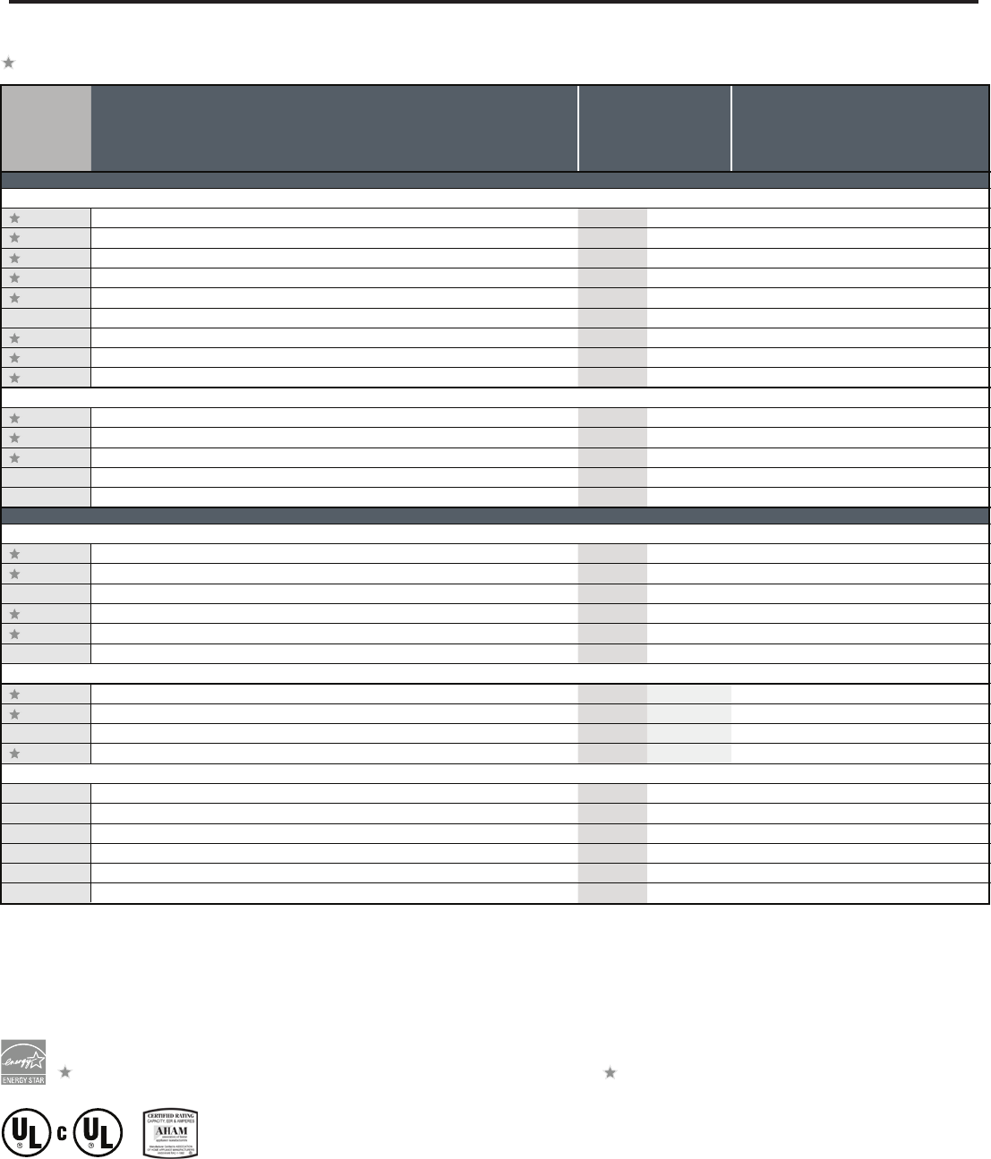
The consumer- through the AHAM Room Air Conditioner Certification Program- can be certain that the AHAM Certification Seal accurately
states the unit’s cooling and heating capacity rating, the amperes and the energy efficiency ratio.
As an ENERGY STAR® partner, Friedrich Air Conditioning Co. has determined that the selected ENERGY STAR® ( ) models meet the ENERGY STAR® guidelines for energy efficiency.
* Sleeve dimensions listed on opposite page.
** Operates on 115 volt and is not equipped with supplemental heat. Will not provide heat at temperatures below 40°F.
Friedrich room air conditioners are designed to operate in outdoor temperatures from 50° F to 115° F.
TwinTemp Heat Pump heating information (shown in red) indicates heat pump heating performance. TwinTemp Electric Heat heating information (shown in red) indicates electric heat strip performance.
For TwinTemp Heat Pump electric heating performance refer to corresponding TwinTemp Electric Heat model.
Due to continuing research in new energy-saving technology, specifications are subject to change without notice.
ENERGY STAR® Models
Cooling
Capacity
BTU/h
Heating
Capacity
Rated
Electrical Characteristics (60 Hertz) Energy
Efficiency
Ratio
EER
Coefficient
Of
Performance
COP
Moisture
Removal
Pints/Hr.
Room Side
Air Circulation
CFM Sleeve*
Weight
Lbs.
Ship/Net Model
Volts
Rated
Cooling
Amps
Cooling
Watts
Heating
Amps
Heating
Watts
ULTRA PREMIUM LINE
QUIETMASTER Programmable
SS08L10 8400 — 115 6.6 737 — — 11.41.6 265 S 114/108
SS10L10 10400 — 115 7.5 867 — — 12.0 2.5 260 S 121/115
SS12L10 11800 — 115 9.0 1000 — — 11.8 2.5 350 S 120/114
SS14L10 14000 — 115 12.0 1305 — — 10.7 3.5 377 S 134/128
SS12L30 12100/11900 — 230/208 4.8/5.0 1052/1017 — — 11.5/11.7 2.9 320 S 120/114
SS16L30 16200/15900 — 230/208 7.4/8.0 1653/1656 — — 9.8/9.6 4.7 360 S 125/119
SM18L30A 17500/17300 — 230/208 7.2/7.7 1620/1570 — — 10.8/10.8 4.5 375 M 169/163
SM21L30 20600/20200 — 230/208 9.4/10.1 2081/2020 — — 9.9/10.0 6.0 425 M 160/154
SM24L30 23500/23000 — 230/208 11.2/12.1 2479/2421 — — 9.5/9.5 7.0 400 M 160/154
XSTAR
XQ05L10A 5500 — 115 5.0 500 — — 11.0 1.2 200 Q 76/70
XQ06L10A 6300 — 115 4.9 548 — — 11.5 1.4 175 Q 76/70
XQ08L10A 8000 — 115 6.8 741 — — 10.8 1.9 175 Q 83/77
XQ10L10A 10000 — 115 9.0 1000 — — 10.0 3.2 180 Q 89/83
XQ12L10A 11700 — 115 11.0 1198 — — 9.8 3.2 200 Q 89/83
PREMIUM LINE
QUIETMASTER
KS12L10 11600 — 115 9.0 1055 — — 11.0 2.5 356 S 120/114
KS15L10 14500 — 115 12.0 1343 — — 10.8 3.5 377 S 134/128
KM18L30 17800/17600 — 230/208 8.1/8.8 1780/1760 — — 10.0/10.0 4.4 400 M 167/161
KM24L30 23500/23000 — 230/208 11.2/12.1 2479/2421 — — 9.5/9.5 7.0 400 M 160/154
SL28L30 28000/27700 — 230/208 13.0/14.2 2947/2916 — — 9.5/9.5 8.8 600 L 207/201
SL36L30A 36000/35700 — 230/208 18.0/19.6 4235/4200 — — 8.5/8.5 11.0 725 L 226/220
TWINTEMP Heat Pump
YS09L10** 9200 7400 115 7.4 767 6.9 733 12.0 3.0 1.7 300 S 117/113
YS13L33 12700/12500 11000/10500 230/208 5.1/5.6 1149/1131 5.3/5.8 1185/1167 11.0/11.0 2.5/2.6 3.5 325 S 121/117
YM18L34 18000/1800016800/16400 230/208 8.5/9.5 1895/1895 8.5/9.0 1867/1822 9.5/9.5 2.8/2.94.7 400 M 170/166
YL24L35 24000/2400022000/21600 230/208 10.9/12.0 2400/2400 11.0/12.0 2444/2400 10.0/10.0 2.7/2.8 7.0 600 L 202/198
TWINTEMP Electric Heat
EQ08L11A 7700 4000115 6.5 733 11.2 129010.5 1.9 175 Q 80/76
ES12L33 12100/11900 10700/8900 230/208 4.8/5.0 1052/1017 16.0/14.7 3500/2900 11.5/11.7 2.9 320 S 115/111
ES16L33 16200/15900 10700/8900 230/208 7.4/8.0 1653/165616.0/14.7 3500/2900 9.8/9.6 4.7 360 S 120/116
EM18L34 17800/17600 13000/10600 230/208 8.1/8.8 1780/1760 19.5/17.0 4200/3500 10.0/10.0 4.4 400 M 164/160
EM24L34 23500/2300013000/10600 230/208 11.2/12.1 2479/2421 19.5/17.0 4200/3500 9.5/9.5 7.0 400 M 160/154
EL36L35A 36000/35700 17300/14300 230/208 18.0/19.6 4235/4200 24.0/22.4 5500/4650 8.5/8.5 11.0 725 L 224/220
CHASSIS SPECIFICATIONS FOR 2009, 2008 MODELS
7
* Minimum extensions when mounted in a window.
** Minimum widths achieved using one side curtain assembly as opposed to both in a standard installation.
† Sleeve P1 does not have thru-the-wall hole dimensions, as these units are fixed chassis and should not be installed thru-the-wall.
NOTE: S,M and L sleeves may be installed in window with no side kits if properly installed.
Sleeve Height Width
Depth
with Front
Shell Depth to
Louvers Minimum
Extension
Into Room*
Minimum
Extension
Outside*
Window Width
Thru-the-wall Installation
Finished Hole
Minimum** Maximum Height Width Max. Depth
Q14" 19 ¾" 21 3∕8" 8 ½" 5 ½" 10 ¾" 22" 42" 14 ¼" 20" 8 ½”
S15 15∕16" 25 15∕16" 27 3∕8" 8 ¾" 3 1∕16" 16 15∕16" 27 3∕8" 42" 16 3∕16" 26 3∕16" 7 3∕8"
M17 15∕16" 25 15∕16" 27 3∕8" 8 ¾" 3 1∕16" 16 15∕16" 27 3∕8" 42" 18 3∕16" 26 3∕16" 7 3∕8”
L20 3∕16" 28" 33 5∕8" 16 ½" 3 3∕16" 18 15∕16" 29 7∕8" 42" 20 3∕8" 28 ¼" 15 1∕8"
TWINTEMP® models include accessories for thru-the-wall
installation only. Window mounting requires use of optional
accessory kit as listed above.
Window Mounting Kits
TwinTemp Model Kit No.
EQ08L11A WIKQ
ES12L33, ES16L33, YS09L10 and YS13L33. WIKS
EM18L34, YM18L34 and EM24L34. WIKM
EL36L35A and YL24L35. WIKL
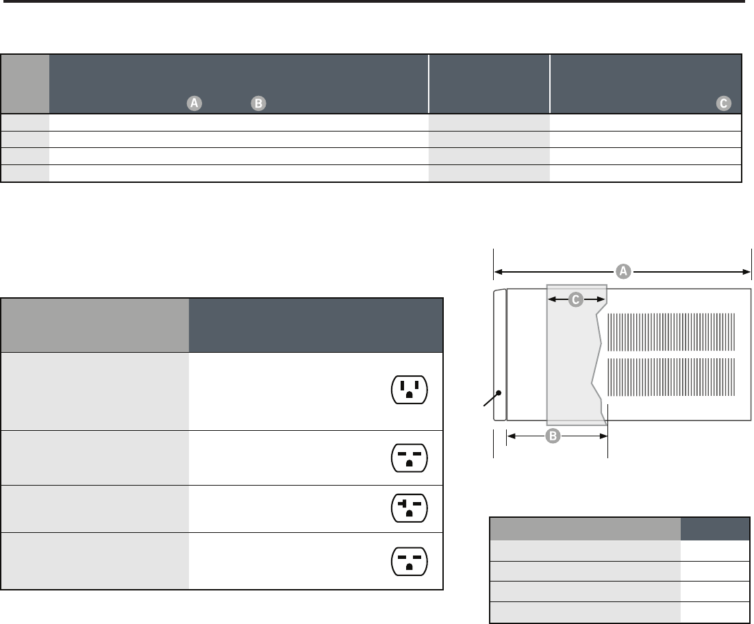
Model
Circuit Rating
Breaker or
T-D Fuse
Plug Face
(NEMA#)
Power Cord
Length (ft.)
Wall Outlet
Appearance
All XQ MODELS.
KS12L10 and KS15L10. SS08L10, SS10L10,
SS12L10 and SS14L10. EQ08L11A.
YS09L10.
125V - 15A 5 - 15P 6
KM18L30.
SS12L30, SS16L30, SM18L30A and
SM21L30.
250V - 15A 6 - 15P 4
KM24L30. SM24L30 and SL28L30.
ES12L33 and ES16L33. YS13L33. 250V - 20A 6 - 20P 4
SL36L30A. EM18L34, EM24L34 and
EL36L35A. YM18L34 and YL24L35. 250V - 30A 6 - 30P 4
(B)
(A)
(C)
Front
SIDE VIEW
INSTALLATION INFORMATION / SLEEVE DIMENSIONS
Circuit Rating / Breaker
8
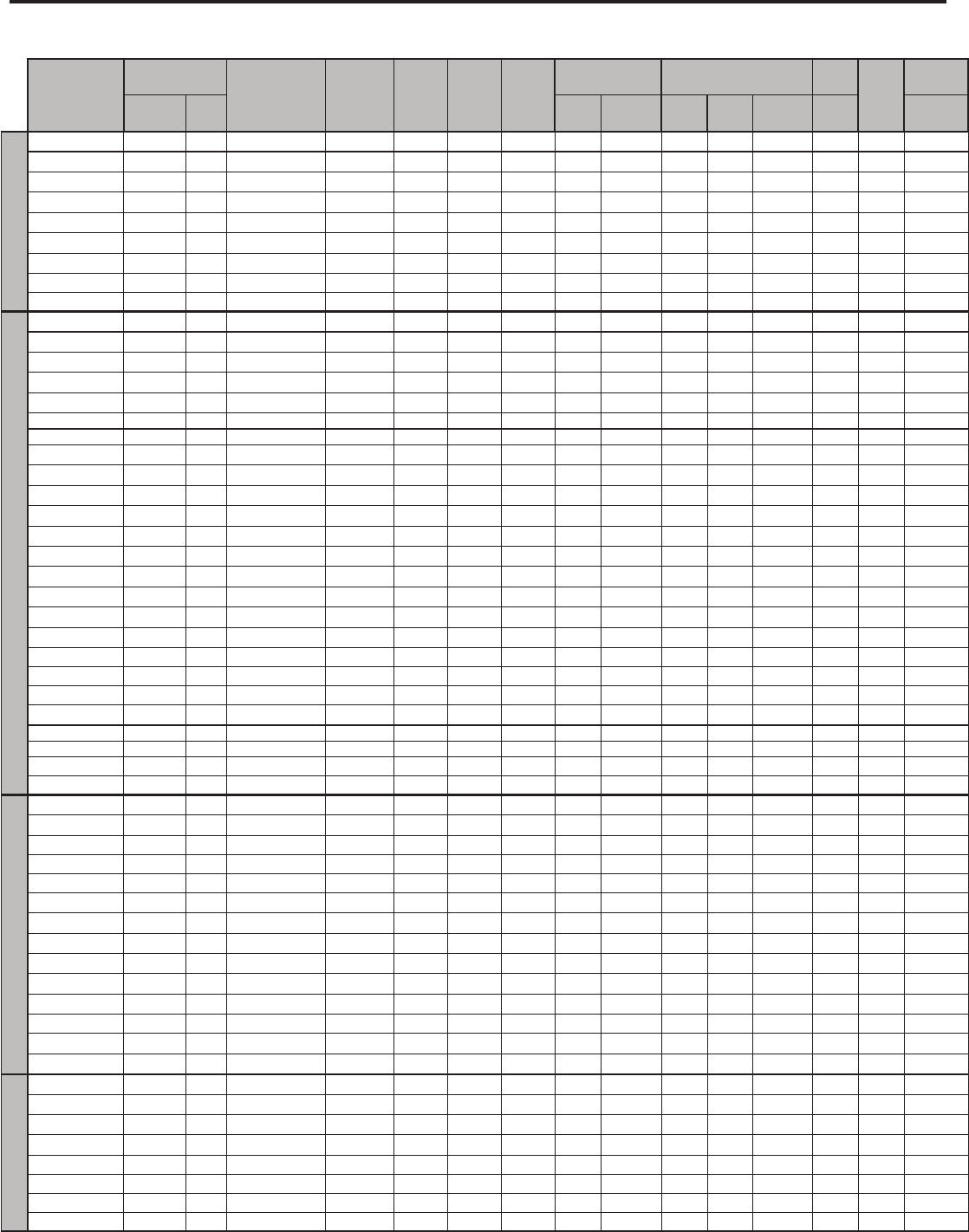
PERFORMANCE DATA FOR 2009, 2008 MODELS
9
COOLING
PERFORMANCE DATA*
EVAP. AIR TEMP. DEG. F CONDENSER
TEMPERATURE DEG. F Discharge Temp Suction Temp Super Heat Sub-Cooling
OPERATING PRESSURES ELECTRICAL RATINGS R-22 REF.
Voltage
BREAKER FUSE
Discharge Air Temp.
Drop F. Suction Discharge Amps Cool Amps Heat Locked Rotor
Amps
Charge in
OZ. 60 Hertz Amps
Q-Chassis
XQ05L10A-C 56 24 119 151 58 13 20 89 255 4.9 28.0 21.4 115 15
XQ06L10A-C 55 26 121 157 65 13 27 87 261 5.0 24.0 21.0 115 15
XQ08L10A-B 52 29 128 167 60 13 33 81 283 6.8 36.2 22.1 115 15
XQ08L10A-E 52 29 125 161 49 13 24 81 280 6.7 36.2 19.8 115 15
XQ10L10A-C 50 31 130 176 65 20 29 75 287 9.2 44.0 19.2 115 15
XQ12L10A-B 51 29 126 166 51 6 30 75 271 11.0 56.0 31.0 115 15
XQ12L10A-C 51 29 126 166 51 6 30 75 271 11.0 56.0 31.0 115 15
EQ08L11A-B 52 29 124 173 69 21 29 82 283 6.5 10.7 36.2 20.0 115 15
EQ08L11A-E 52 29 125 161 49 13 24 81 280 6.7 10.7 36.2 19.8 115 15
S-Chassis
SS08L10-E 56 24 116 157 68 16 18 86 250-260 6.6 36.2 27.0 115 15
SS08L10-F 56 24 116 157 68 16 18 86 250-260 6.6 36.2 27.0 115 15
SS08L10-G 53 24 116 157 57 13 23 85 250-260 6.5 36.2 27.0 115 15
SS10L10-D 57 23 117 166 65 16 23 82 243 7.5 42.0 26.0 115 15
SS10L10-E 57 23 117 166 65 16 23 82 243 7.5 42.0 26.0 115 15
KS12L10-E 52 28 122 170 60 12 26 83 266 9.0 44.0 30.0 115 15
KS12L10-F 52 28 122 170 60 12 26 83 266 9.0 44.0 30.0 115 15
SS12L10-E 53 27 124 169 62 13 30 82 266 9.3 44.0 32.0 115 15
SS12L10-F 53 27 124 169 62 13 30 82 266 9.3 44.0 32.0 115 15
KS15L10-C 51 30 125 182 62 16 29 77 278 12.2 61.0 29.0 115 15
KS15L10-D 51 30 125 182 62 16 29 77 278 12.2 61.0 29.0 115 15
SS14L10-D 53 27 125 184 62 15 27 78 268 12.3 61.0 29.2 115 15
SS14L10-E 53 27 125 184 62 15 27 78 268 12.3 61.0 29.2 115 15
SS12L30-E 58 22 122 174 66 17 28 84 261 4.7 21.0 31.0 208 / 230 15
SS12L30-F 58 22 122 174 66 17 28 84 261 4.7 21.0 31.0 208 / 230 15
SS16L30-D 50 31 130 176 53 8 35 77 279 7.9 35.0 32.1 208 / 230 15
SS16L30-E 50 31 130 176 53 8 35 77 279 7.9 35.0 32.1 208 / 230 15
ES12L33-D 58 22 122 174 66 17 28 84 261 4.7 15.1 21.0 31.0 208 / 230 20
ES12L33-E 58 22 122 174 66 17 28 84 261 4.7 15.1 21.0 31.0 208 / 230 20
ES16L33-C 49 32 130 179 50 8 34 75 279 7.4 15.1 35.0 32.0 208 / 230 20
ES16L33-D 49 32 130 179 50 8 34 75 279 7.4 15.1 35.0 32.0 208 / 230 20
YS09L10-F 64 16 116 164 71 20 19 87 249 7.4 7.0 44.0 28.0 115 15
YS09L10-G 64 16 116 164 71 20 19 87 249 7.4 7.0 44.0 28.0 115 15
YS13L33-D 51 29 122 172 65 18 30 80 269 5.5/5.1 5.7/5.3 24.0 32.0 1 20
YS13L33-E 51 29 122 172 65 18 30 80 269 5.5/5.1 5.7/5.3 24.0 32.0 1 20
M-Chassis
KM24L30-C 50 31 132 187 56 14 37 70 287 11.2 68.0 53.0 208 / 230 20
KM24L30-D 50 31 132 187 56 14 37 70 287 11.2 68.0 53.0 208 / 230 20
YM18L34-D 61 19 126 187 67 24 28 73 280 9.2/8.75 8.8/8.3 41.0 43.0 208/230 30
YM18L34-E 61 19 126 187 67 24 28 73 280 9.2/8.75 8.8/8.3 41.0 43.0 208/230 30
EM18L34-C 49 31 125 175 63 21 31 72 271 8.1 18.9 42.0 39.5 208 / 230 15
KM18L30-C 49 31 125 175 63 21 31 72 271 8.1 42.0 39.5 208 / 230 15
KM18L30-D 49 31 125 175 63 21 31 72 271 8.1 42.0 39.5 208 / 230 15
SM18L30A-D 54 26 121 171 61 13 25 81 262 7.7/7.1 37.0 45.0 208/230 15
SM18L30A-E 54 26 121 171 61 13 25 81 262 7.7/7.1 37.0 45.0 208/230 15
SM21L30-E 48 32 125 173 52 13 25 75 278 9.6/9.3 43.0 43.0 208/230 15
SM21L30-F 48 32 125 173 52 13 25 75 278 9.6/9.3 43.0 43.0 208/230 15
EM24L34-B 50 31 132 187 56 14 37 70 287 11.2 25.0 68.0 53.0 208 / 230 30
SM24L30-C 50 31 132 187 56 14 37 70 287 11.2 68.0 53.0 208 / 230 20
SM24L30-D 50 31 132 187 56 14 37 70 287 11.2 68.0 53.0 208 / 230 20
L-Chassis
SL28L30-D 53 28 128 172 56 13 29 73 259 13.0 68.0 50.1 208 / 230 20
SL28L30-E 53 28 128 172 56 13 29 73 259 13.0 68.0 50.1 208 / 230 20
SL36L30A-D 49 31 133 192 53 12 37 70 287 17.2 91.0 57.6 208 / 230 30
SL36L30A-E 49 31 133 192 53 12 37 70 287 17.2 91.0 57.6 208 / 230 30
EL36L35A-D 49 32 133 194 53 13 38 70 302 18.0 25.0 91.0 60.0 208 / 230 30
EL36L35A-E 49 32 133 194 53 13 38 70 302 18.0 25.0 91.0 60.0 208 / 230 30
YL24L35-E 52 28 124 175 65 22 29 74 268 11.9/11.1 11.7/11.0 68.0 73.0 208/230 30
YL24L35-F 52 28 124 175 65 22 29 74 268 11.9/11.1 11.7/11.0 68.0 73.0 208/230 30
*Rating Conditions: 80 degrees F, room air temp. & 50% relative humidity, with 95 degree F, outside air temp & 40% relative humidity, all systems use R22.
ELECTRICAL DATA
ELECTRIC SHOCK HAZARD
WARNING
Turn off electric power before service or
installation.
All electrical connections and wiring MUST be
installed by a qualied electrician and conform to
the National Electrical Code and all local codes
which have jurisdiction.
Failure to do so can result in personal injury or
death.
Not following the above WARNING could result in re or
electically unsafe conditions which could cause moderate
or serious property damage.
Read, understand and follow the above warning.
NOTICE
FIRE HAZARD
10
Wire Size Use ONLY wiring size recommended for single outlet branch circuit.
Fuse/Circuit Breaker Use ONLY the correct HACR type and size fuse/circuit breaker. Read electrical ratings on unit’s
rating plate. Proper circuit protection is the responsibiity of the homeowner.
Grounding Unit MUST be grounded from branch circuit through service cord to unit, or through separate
ground wire provided on permanently connected units. Be sure that branch circuit or general
purpose outlet is grounded.
Receptacle The eld supplied outlet must match plug on service cord and be within reach of service cord.
Do NOT alter the service cord or plug. Do NOT use an extension cord. Refer to the table above
for proper receptacle and fuse type.
The consumer - through the AHAM Room Air Conditioner Certication Program - can
be certain that the AHAM Certication Seal accurately states the unit’s cooling and
heating capacity rating, the amperes and the energy efciency ratio.
*HACR: Heating Air Conditioning and Refrigeration
11
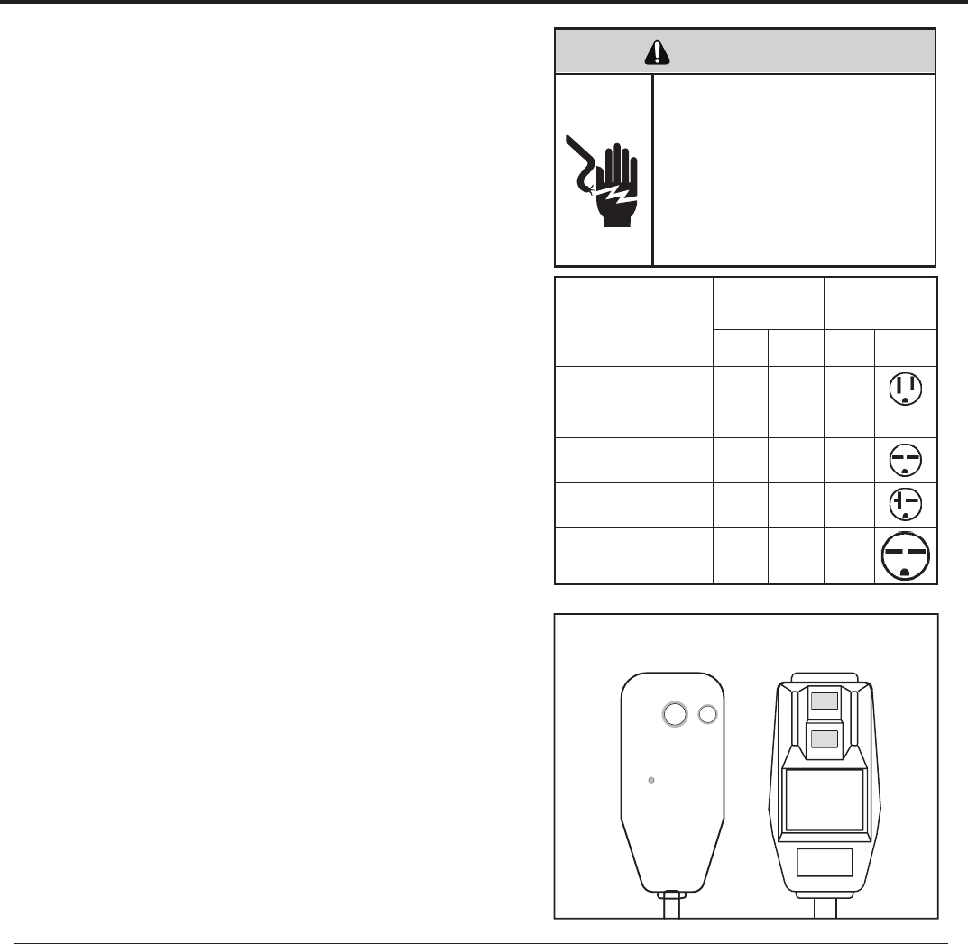
ELECTRICAL SHOCK HAZARD
WARNING
Make sure your electrical receptacle has the same
configuration as your air conditioner’s plug. If
different, consult a Licensed Electrician.
Do not use plug adapters.
Do not use an extension cord.
Do not remove ground prong.
Always plug into a grounded 3 prong outlet.
Failure to follow these instructions can result in
electrical shock, serious injury or death.
Keep the filter clean
Make sure that your air conditioner is always in top performing condition
.ylralugerretlifehtgninaelcyb
Provide good air flow
Make sure the airflow to and from the unit is clear. Your air conditioner puts the
conditioned air out at the top of the unit, and takes in unconditioned air at the
bottom. Airflow is critical to good operation. It is just as important on the outside
.dekcolbtonsiroiretxetinuehtdnuorawolfriaehttahtgnidliubehtfo
Unit placement
If your air conditioner can be placed in a window or wall that is shaded by a tree
rosepardgnisU.yltneiciffeeromneveetarepolliwtinueht,gnidliubre hto naro
blinds on the sunny side of the dwelling will also add to your unit’s efficiency.
Insulation
Good insulation will be a big help in maintaining desirable comfort levels.
Doors should have weather stripping. Be sure to caulk around doors and
windows.
Proper installation of seal gasket
Make sure the seal gasket has been installed properly to minimize noise
and improve effi ciency. If the seal gasket has not been installed, please
refer to Step 14 of the installation instructions.
Also, if you switch from Cool mode to Fan Only, and switch back to
COOL mode, there is a three minute delay before the compressor comes
back on.
For the best cooling performance and highest energy efficiency
WARNING: Before operating your unit
Make sure the wiring is adequate for your unit.
If you have fuses, they should be of the time delay type. Before you install
rekaerbtiucricehtfognitaregarepmaehttahteruseb,tinusihtetac olerro
or time delay fuse does not exceed the amp rating listed in Figure 1.
DO NOT use an extension cord.
The cord provided will carry the proper amount of electrical power to the
.tonlliwdrocnois netxena;tinu
Make sure that the receptacle is compatible with
the air conditioner cord plug provided.
This insures proper grounding. If you have a two prong receptacle you
will need to have it replaced with a grounded receptacle by a certifi ed
electrician. The grounded receptacle should meet all national and local
codes and ordinances. Under no circumstances should you remove the
ground prong from the plug. You must use the three prong plug furnished
with the air conditioner.
Test the power cord
All Friedrich room air conditioners are shipped from the factory with a
Leakage Current Detection Interrupter (LCDI) equipped power cord. The
LCDI device meets the UL and NEC requirements for cord connected air
conditioners.
To test your power supply cord:
1. Plug power supply cord into a grounded 3 prong outlet.
2. Press RESET (See Figure 2).
3. Press TEST (listen for click; Reset button trips and pops out).
4. Press and release RESET (listen for click; Reset button latches and
remains in). The power supply cord is ready for operation.
NOTE: LCDI device is not intended to be used as a switch.
Once plugged in the unit will operate normally without the need to reset
the LCDI device.
If the device fails to trip when tested or if the power supply cord is
damaged it must be replaced with a new supply cord from the manufac-
turer. We recommend you contact our Technical Assistance Line at
(800) 541-6645 ext. 845. To expedite service, please have your model
and serial number available.
MODEL
CIRCUIT RATING
OR TIME DELAY
FUSE
REQUIRED WALL
RECEPTACLE
AMP VOLT NEMA
NO.
SS08 • SS10 • SS12 • SS14
XQ06 • XQ08 • XQ10 • XQ12
EQ08
KS12 • KS15 • YS09 • XQ05 15 125 5-15R
SS12 • SS16 • SM18
SM21 • KM18 15 250 6-15R
SM24 • SL28 • KM24
YS13 • ES12 • ES16 20 250 6-20R
SL36 • YM18 • YL24
EM18 • EM24 • EL36 30 250 6-30R
Figure 1
Figure 2
TEST
RESET
WARNING
TEST BEFORE EACH USE
1. PRESS RESET BUTTON
2. PLUG LDCI INTO POWER
RECEPTACLE
3. PRESS TEST BUTTON,
RESET BUTTON SHOULD
POP UP
4. PRESS TEST BUTTON,
FOR USE
DO NOT USE IF ABOVE TEST
FAILS
WHEN GREEN LIGHT IS ON
IT IS WORKING PROPERLY
RESET TEST
NOTE: Your LCDI device will resemble one of these illustrations.
12
A/C
Stop
Mode
Temp
Fan
Timer
O
F
/
O
C
A/C
Start Timer
On/O
1-4
Speed
Smart
Fan
Check
Filter
Set
Hour
Power
Cool
Money
Saver
®
PM
Fan
Only
Press to reset
13
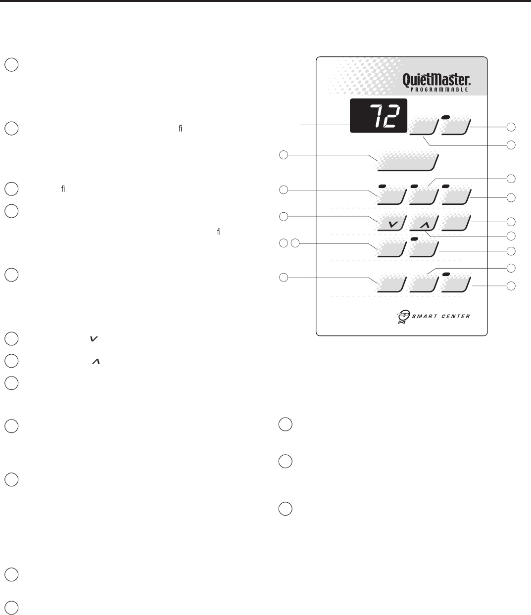
DISPLAY
8
5
4
2
15
10
7
11
9
6
3
1
14
12
Figure 3
To start unit
1If yourair conditionerisinstalledandpluggedintoaproper re-
hcuoT.ogotydaersiti,elc at pec Power buttononce. The unit will
automatically be in Coolmode with the temperature set at 75°F
(24°C) and the fan speed at F1, the sleep setting. There is a 3-
minutedelay before the compressor willturn on. (See "Automatic
Component Protection" on this page).
2Should the Check Filter light turn on when you rst turn on the unit,
touch Check Filter to turn off the light. Check Filter light will come
Clean filter..esufosruoh052ret fano
Touch Check Filter to reset.
To set mode of operation
3When you rst turn on the unit, it will be in the Coolmode(light on),
with constant fan.
4Touch MoneySaver®(light on) to activate the MoneySaver®feature.
This cyclesthefanwiththe compressor so that thefandoes not
.noit ac
i dim uh edsevorpmidnaygrenesevassihT.emitehtllanur
(MoneySaver®will also run the fan to sample the return air tempera-
ture if the off cycle is too long). Or you may prefer constant fan for
more air movement. To return to constant fan, touch Cool.
5Touch Fan Only (light on) if you want only the fan to run. You may want
to use this feature in conjunction with the Fresh Air / Exhaust lever to
bringoutside air intoaroom, or to exhaust stale air. (See page 7, "Fresh
Air and Exhaust Control" for more information.)
To adjust temperature [60°F (16°C) to 90°F (32°C)]
6COOLER – Touch and hold until the display shows the desired
roomtemperature.
7WARMER– Touch andholduntil the display shows the desired
room temperature.
8FAHRENHEIT / CELSIUS – Touch ºF/ºC to show the temperature
in Celsius,touch againtoshow Fahrenheit.
To adjust fan speed
9Touch 1-4 Speedto see current setting. Touch again to change
deepswolsi2F,)GNITTESPEELS(gnit testsewolehtsi1F.deeps
(LOW), F3 is medium speed (MED), F4 is high speed (HIGH).
To activate smart fan
10 Touch Smart Fan (light on). Smart Fan willadjust the fan speed
,elpmaxeroF.leveltrofmocderisedehtniatniamotyl lac i tam ot ua
do ir epdednetxenarofnepoeraemohruoynisroodedistuoehtfi
of time, or more people enteraroom, Smart Fan may adjust to a
higher fan speed to compensatefor the increasedheat load. This
keepsyou from having to adjust the fan speed on your own. Smart
Fan cannot be activated in the Fan Only mode.
To deactivate smart fan
11 Touch 1-4 Speed, and select your desired fan speed.
To set hour clock
12 PressSetHouronce to see the current clock setting. Continue
pressing the buttonuntil the hour closest to the actual time appears
in the display.
MAKE SURE YOU SET A.M. AND P.M. PROPERLY.Alight will appear in
the upper left corner of the display when the hour is P.M.
NOTE: Minutes will NOT show on display.
To set the timer
NOTE: .snoitcnufremittesotgni tpmet taerofebkcolcruoHteS
You can set the A/C Start andA/C Stop ruohenofomum i nimaremit
apart and a maximumof 23 hours apart.
13 TIMER STOP - Press the A/C Stop buttonand continuepressing
until the houryouwant the unittoshut off appears in the display
(A.M. or P.M.). The stop time for cooling will then be set.
14 START TIME - PressA/C Start to view the current start time for
cooling. Continue pressinguntil the houryouwant the unit to start
appears in the display (A.M. or P.M.). The start timefor cooling will
then be set.
15 PresstheTimer On/ Off button once to activate (light on) the timer
function. Touch Timer On/ Off again(light off) to cancel the timer
-esneebevahsemitffodnanoehtecnO.er
is edosuoyfinoitcnuf
lected, they will remainin memory, and cycle dailyuntil changed.
NOTE: eht,de tpur ret nisirewoprodeggulpnusitinufI Set Hourbutton
ehtrotes erebtsum Timer On/ Off functions will not work.
Automatic component protection
.noitcetorPtnen op moCcitamotuAhtiwdeppiuqesitinuruoY
To protect the compressor of the unit, there isathreeminute time delay if you
turn the unit off or if power is interrupted. The fan will not be affected.
How to operate the Friedrich room air conditioner(QuietMaster Programmable)
13
* A Friedrich RC1 wireless remote control can be used to operate all
QuietMaster® Programmable models.
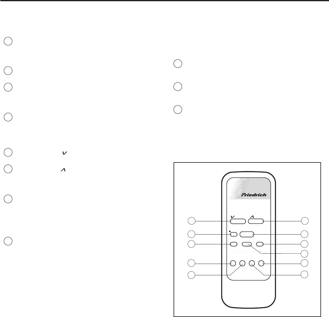
Figure 4
To start unit
1POWER - PressthePower buttononce. The unit will automatically
turn on in the mode and fan speed it was last left on.
To set mode of operation
2COOL - PresstheCoolbutton to automatically switch the operating
mode to COOL.
3FAN ONLY - PresstheFan Only buttonifyouwant to run the fan only.
You may want to use thisfeature in conjunction with the Fresh Air/
Exhaustif youwant to bringoutside airinto the room, or exhaust stale
air.
4MoneySaver®- PresstheMoneySaver®button to activate the
MoneySaver®feature. This cyclesthefanwiththe compressor so
that the fan does not run all the time.
To adjust temperature
5COOLER - PresstheCooler button to raise the temperature
setting.
6WARMER - Pressthe Warmer button to lower the temperature
setting.
To adjust fan speed
7FAN SPEED- Press the Fan Speed buttontoseethecurrent set-
ting. Press again to change the fan speed. F1 is the lowest setting
(SLEEP SETTING), F2 is low speed (LOW), F3 is medium (MED),
and F4 is high (HIGH).
To set the hour clock
8SET HOUR CLOCK - PressSetHouronce to see the current clock set-
ting. Continue pressing the button until you arrive at the current time.
MAKE SURE YOU SET THE A.M. AND P.M. PROPERLY. (NOTE:
MINUTES ARE NOT SHOWN ON THE DISPLAY.)Alight will appear in
the upper left corner of the display when the hour is P.M.
How to use the remote control*(QuietMaster Programmable)
To set the timer
NOTE: Set the hour clock before attempting to set timer functions. You
can set the timer On/Off aminimumofonehourapart, and a maximum
of 23 hours apart.
9TIMER START - PressStart to view the current start timefor cool-
ing. Continue pressing the Start button until you arrive at the start
time you desire. The start time for cooling will then be set.
10 TIMER STOP - Press the Stopbutton. Continue pressingtheStop
buttonuntil you arrive at the stop time you desire. The stop time for
cooling will then be set.
11 TIMERON/OFF - Press the On/off buttononce to activate(light on)
or deactivate (light off) the timer. Once the Start andStoptimes
have beenselected, they willremain in memory, and cycle dailyuntil
changed.
NOTE: If the unit is unplugged or the power is interrupted, the HOUR
CLOCK must be reset or the Timer On/off functions will not work.
Money
Fan
Timer Operation
Set Hr.
Stop
Start
Temperature
Fan
Cool
On/O
Power
Cooler
Only Speed Saver®
Warmer
8
10
7
11
9
43
1
2
56
14
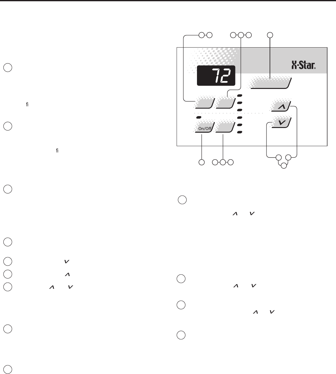
To startunit
siti,elc at pec erreporpaotnideggulpdnadellatsnisirenoitidnocriaruoyfI
ready to go.The firsttimethe unit is started, thecompressorwilldelay for three
minutes.See AutomaticComponentProtectiononthe followingpage.
1Touchthe Power button once.The unitwill automaticallybeinCool
mode with the temperature setat75°F (24°C) andthe fanspeed at
F1, thesleep setting.
To setmodeofoperation
When yourstturnthe uniton, it will be in theCool mode (lighton),with
constant fan.
2Touchthe Modebutton once to activatethe MoneySaver®(lighton).
MoneySaver®ros serp mocehthtiwnafehtselcyctahterutaefasi
so that thefan does notrun allthe time.Thissaves energy and
eromrofnaftnats nocreferpyamuoyrO.noit ac
i dim uh edsevorpmi
ehthcuot,naftnatsnocotnruterot(tnem evomria Modebutton two
more times).
In order to runthe fanbyitself, do thefollowing:
3Continuing from MoneySaver®mode (light on), touchthe Mode button
once to activate theFANONLYfeature(lighton).
The FANONLYsettingwillcirculate air in the roomwithout thecom-
pressorcomingon.
To adjusttemperature
4Usethe Modebutton to select eitherthe COOL or MoneySaver®
function
5COOLER – Touch the button to lower theroomair temperature.
6WARMER – Touch the button to raisethe roomair temperature.
7Pressboth the and ehthctiwsotemitemasehttasnottub
temperature readoutfrom Fahrenheit(°F)toCelsius(°C).
Repeat step 7 to switch from °C back to °F.
To adjust fan speed
8Touchthe FanSpeed button to seethe currentsetting. Touchitagain
to change speed. F1isthe lowest setting(SLEEPSETTING/LOW),
F2 is MEDIUM,and F3 is HIGH.
To activate SmartFan
9Thereisafourth option,SF, when selectingthe fanspeed.Thisis
the SMARTFAN function.SMART FANDOESNOT OPERATEIN
CONJUCTION WITH THEFAN ONLY MODE.
SmartFan will adjustthe fanspeed automaticallytomaintain the
desiredcomfort level. Forexample,ifthe outsidedoors in your home
are opened foranextended period of time,ormorepeople entera
room,Smart Fanmay adjusttoahigherfan speedtocompensate
forthe increasedheatload. This keepsyou from having to adjustthe
fanspeed on your own.
Howtooperate the Friedrich room airconditioner(XQmodels)
PM
Temp/Hour
Cool
Money Saver
®
Fan Only
Clock
Start Time
Stop Time
Power
Fan
SpeedMode
Timer Set
Hour
10 11 12
13 7
3 4
56
18 9 2 Figure 5
To setthe hour clock
10 Touchthe SetHourbutton to seethe currentsetting (clock light
comeson).The numberthatisdisplayed is the approximatetime
(hour only).Use theandbuttonstochange thesettings.BE
SURETO SETA.M.AND P. M. ACCORDINGLY. (P.M.isindicated
by ared lightinthe upperleftcornerofthe display).
To setthe timer
NOTE:Setthe HOUR CLOCKbefore attempting to settimer functions.
Youcan setthe STARTandSTOP timesaminimumofone hour apart,and
amaximumoftwenty-three hours apart.
11 Aftersetting thetime,press theSet Hour button once (Start light
comeson).Use theandbuttonsto selectthe time that the
unit will START.
12 After selectingthe START time,press theSetHourbutton once more
(Stoplight comeson).Use theandbuttonstoselect the time
that the unitwillSTOP.After selecting the stoppingtime, pressthe
Set Hourbutton once.
13 Pressthe TimerOn/Offbutton (light turnson) to activate thetimer
function. To deactivate this function, press theTimerOn/Offbutton
once again (lightturns off).Oncethe on andoff timeshavebeen
selected,theywillremaininmemoryand cycle dailyuntil changed.
NOTE:If the unitisunplugged or thepower is interrupted,the HOUR
mustbereset or theTimerOn/Offwill notfunctionwhendesired.
Automatic componentprotection
Your unit is equipped with Automatic Component Protection. To protectthe
compressorofthe unit, thereisathree minutestart delayifyou turn the unit
offorifpowerisinterrupted.The fanoperation will notbeaffected. Also,ifyou
switch from Cool mode to Fan Only,and switch back to Cool mode,there
is athree minute delaybeforethe compressor comesbackon.
15
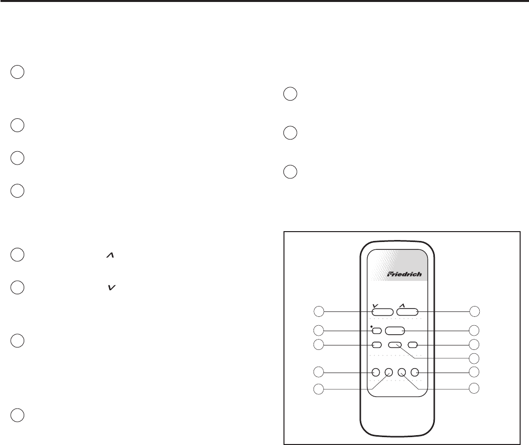
To set the timer
NOTE: You can set the START andSTOP timesaminimum of onehour
apart, andamaximum of 23 hours apart.
9TIMER START - Press Start .gniloocrofemittratstnerrucehtweivot
ContinuepressingtheStart buttonuntil you arrive at the start time
you desire. The start time for cooling will then be set.
10 TIMER STOP - Press the Stop button. Continue pressing the Stop
buttonuntil you arrive at the stop timeyoudesire. The stop timefor
cooling will then be set.
11 TIMER ON / OFF - Press the On/Off button to activate(light on) or
deactivate (light off) the timer. Once the on and off times have been
selected, they will remain in memory and cycle dailyuntil changed.
NOTE: If the unit is unplugged or the power is interrupted, the Set Hr.
function must be reset or the On/Off function will not work.
How to use the remote control
To start unit
1POWER - Press the Power buttononce. Theunitwill automatically
start in the mode and fanspeed it waslastleft on.
To set mode of operation
2COOL - Press the Coolbuttontoautomaticallyswitch the operating
mode to COOL.
3FAN ONLY - Press the Fan Only button if you want to run the fan
only.
4MoneySaver®- Press the MoneySaver®button to activate the
MoneySaver®feature. This feature cycles the fan with the compres-
sor so that the fan does not run all the time.
To adjust temperature setting
5WARMER- Press the Warmer button to raise the temperature
setting.
6COOLER - Press the Cooler button to lower the temperature
setting.
To adjust fan speed
7FAN SPEED - Press the FanSpeedbutton to see the current set-
ting.Pressagain to change the fanspeed.F1 is the lowest setting
(SLEEP / LOW), F2 is MEDIUM,F3 is HIGH, and SF is theSMART
FAN setting.
To set the hour clock
8SET HOUR CLOCK - Press Set Hr. once to see the current clock
setting. Continuepressing the buttonuntil you arrive at the current
time (Hour only). Minutes are notshown on the display. Make sure
that the A.M. / P.M. setting is correct.
Money
Fan
Timer Operation
Set Hr.
Stop
Start
Temperature
Fan
Cool
On/O
Power
Cooler
Only Speed Saver
®
Warmer
8
10
7
11
9
43
12
56
Figure 6
Additional RC1 wireless remote controls can be purchased from your Friedrich dealer.
(XQ models)
16
Allow3min. between restarts
SPEED
Sleep
Setting
Low
Cool
Medium
Cool
High
Cool
Fan
Only
O
MIN MAX
Money Saver
®
Yes No
Allow 3 min. between restarts
Money Saver
®
MAX
COOL
MAX
HEAT
Low
Cool
Med
Cool
High
Cool
Low
Heat
Med
Heat
High
Heat
Fan
OnlyO
Yes No
To start unit
If your air conditioner is installed and plugged into a properly grounded
.eta repootydaersiti,elc atpec er
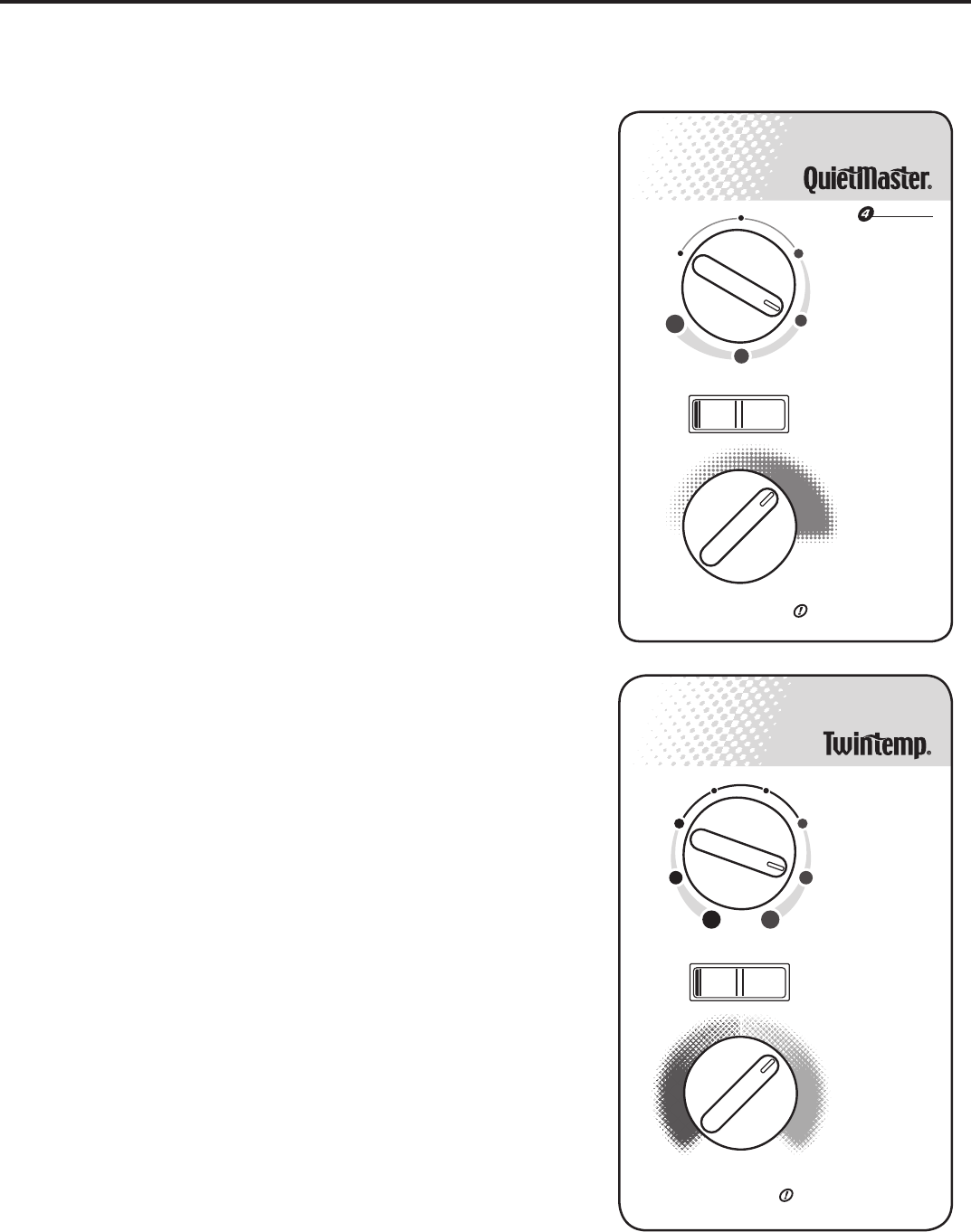
Mode control (QuietMaster)
The upper dial (Figure 7) allows you to select cooling at four different
speeds, as well as Fan Only (Models SL28 and SL36 only have three
cooling speeds.).
Off - to turn the unit off.
High Cool- for quick cooling.
Medium Cool.erutarepmetderis edaniatniamot-
Low Cool - when cooling demand is low.
Sleep Setting- for nighttime use, or when cooling demand is low.
Fan Only - to circulate air in the room without the compressor coming on.
The Fan Only setting can also be used with the Exhaustevomerotgnittesria
stale air or smoke from the room; or it can be used with the Fresh Air setting
to bring outside air into the room. This is especially useful in the spring and fall
ehT.yras se cenebtonyamgniloocne
hw Fresh Air and Exhaust controls
ehtsilortnocsihtfonoitis opretnecehT.aeraegrahcsidriareppuehtniera
normal, or closed position, which recirculates air for maximum performance
e.domgniloocehtni
Mode control (Twintemp)
,sdeepstnereffideerhttagnitaehrognilooctcelesotuoyswollalaidsihT
as well as Fan Only (Figure 8).
Off - to turn the unit off.
High Cool or High Heat.esnops erkciuqrof-
Medium Cool or Medium Heat .erutare
pmetderis edaniatniamot-
Low Cool or Low Heat - for nighttime use, or when demand is low.
Fan Only - to circulate air in the room without the compressor coming on.
The Fan Only ehthtiwdesueboslanacgnittes Exhaustotgnittesria
ehthtiwdesuebnactiro,moorehtmo
rfekomsroriaelatsevom er Fresh
Air dnagnirpsehtniyllaicep se,moorehtotniriaedistuognirbotgnittes
.yras se cent’nsig
niloocnehwllaf
The Fresh Air and Exhausta.eraegrahcsidriarep puehtnieraslortnoc
ro,lamronehtsilortnocsihtfonoitisopretnecehT
ehtniecnam rofrepmumixamrofriasetaluc ric er
hcihw,noitis opdesolc
.edomgnilooc
NOTE: ehtnehwtae
hehtgnitav itcatsrfinehwrodonaecitonyamuoY
yamtahtffogninrubtsudoteudsisihT.nosemoctnem e letaehcirtcele
.l
amrons
isihT.rem musehtgnirudliocehtnodere htagevah
Temperature control
esiw kcolctinruT.tatsomrehtehtsilenaplortnocehtnolaidmottobehT
for cooler temperature and counterclockwise for warmer.
Money Saver® switch
This rocker switch can be depressed to either Yes or No. In the Yes position
ros serp mocdnanafehthtoB.noitarepolac imonocetsomehtteglliwuoy
ataerutarep metdetcelesehtgniniatniam,re hteg otffodnanoelc yclliw
gniloocehtniyltneic fifeeromyt
idim uhehtgnicud erdnale veltnats nocerom
gnitaehr
ogniloocnisitinuehtnehweta re poylnolliwlortnocsihT.edom
mode. In the No sitinuehtsagnolsayltnatsnocnurlliwnafeht,noitisop
.edomgnitaehrogniloocehtni
NOTE: The YS09 is a 115 volt model and does not provide adequate heat
.snoitac ilp paetamilcmrawrofdengisedsitcu dorpsihT.)C°3(F°73woleb
How to operate the Friedrich room air con di tion er
(QuietMaster / Twintemp models)
Figure 7
Figure 8
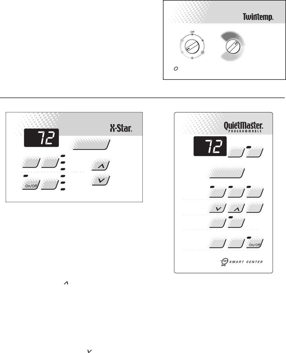
EQ08 models
Function Control
The left knob is a six position control that allows you to
select heat or cool in either low speed or high speed. Plus
you can select fan only if you wish.
Function Control
The right hand knob is the thermostat - turn it clockwise for
cooler, counter-clockwise for warmer (See Figure 9).
Low
Cool
High
Cool
Low
Heat
High
Heat
MAX
COOL
MAX
HEAT
Fan
Only
Allow3 min. between restarts
!
A/C
Stop
Mode
Temp
Fan
Timer
O
F
/
O
C
A/C
Start Timer
1- 4
Speed
Smart
Fan
Check
Filter
Set
Hour
Power
Cool
Money
Saver
®
PM
Fan
Only
Press to reset
PM
Te mp/Hour
Cool
Money Saver
®
Fan Only
Clock
StartTime
Stop Time
Power
Fan
SpeedMode
Timer Set
Hour
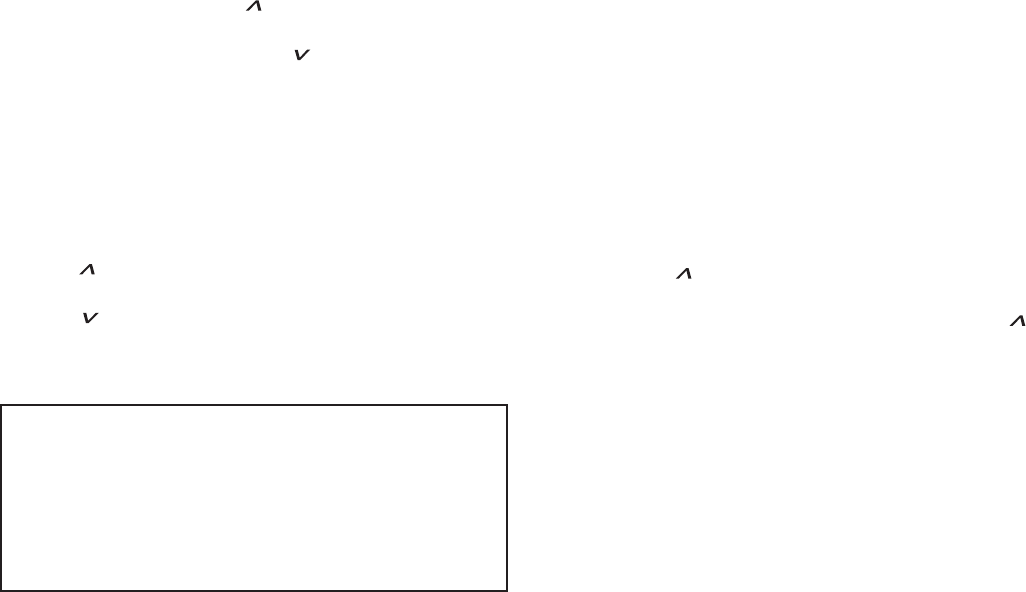
TESTING THE ELECTRONIC CONTROL
BOARDS FOR QME & XQ MODELS
Checking Room Temperature:
1. Check the room temperature at the electronic control
pad by pressing the “FAN SPEED” button and the
temperature “UP” button at the same time on XQ models.
2. Check the room temperature at the electronic control
pad by pressing at the same time the “FAN SPEED”
button and the “TEMP ” button on QME models.
The indoor temperature will display for 10 seconds. Indoor
temperature can be viewed in all modes, including the
TEST mode. The display can be changed back to SET
temperature by pressing any key, except the ON/OFF
button, or after 10 seconds has elapsed.
Activating Test Mode:
Activate test mode by pressing at the same time the
“MODE” button and the “TEMP ” button on XQ
models. LEDs for Hour, Start, and Stop will blink 1 bps
while Test Mode is active.
Activate test mode by pressing at the same time the
“MONEY SAVER” button and the “CHECK FILTER”
button on QME models. LED for the Filter Alert will blink
1 bps while Test Mode is active.
Test Mode has duration of 90 minutes. Test Mode
can be activated under any conditions, including
Off. Test Mode is cancelled by pressing the On/Off
button, unplugging the unit, or when the 90 minutes
is timed out. All settings revert to the factory default
settings of Cool, 75 degrees F, Timer and Set Hour
features are nonfunctional.
Test Mode overrides the three-minute lockout, all
delays for compressor and fan motor start / speed
change, and no delay when switching modes.
Test Mode default settings are ON, Money Saver,
60 degrees F, and High fan speed.
17
FIGURE 9
FIGURE 11
FIGURE 10
Activating Error Code Mode: (Submode of Test Mode)
Unit must be in Test Mode to enter Error Code Mode
1. Activate Error Code Mode by pressing the “TIMER ON/
OFF” button on XQ models. LED for the “TIMER ON/
OFF” will ash 1 bps while Error Code Mode is active.
Pressing the “TEMP/HR ” button will display 00.
Consecutive presses will scroll through all error codes
logged. Press the “TEMP/HR ” button to see the
reverse order of all error codes logged. When the end of
logged error codes is reached the temperature set point
will appear.
Activate Error Code Mode by pressing at the same time
the “A/C START” button and the “ON/OFF” button on
QME models. LED for the “TIMER ON/OFF” will ash
1 bps while Error Code Mode is active. Pressing the
“TEMP ” button will display 00. Consecutive presses
will scroll through all error codes logged. Press the
“TEMP ” button to see the reverse order of all error
codes logged. When the end of logged error codes is
reached the temperature set point will appear.
IMPORTANT: Error Codes are cleared from the log by
exiting from Error Code Mode. To exit on XQ models,
press Timer On/Off button. To exit QME models,
press A/C Start and On/Off buttons. Or unplug unit to
exit Error Code Mode. Plug unit in after 5 seconds to
resume normal operation of unit.
TESTING THE ELECTRONIC CONTROL
ERROR CODE LISTINGS
E1 SHORT CYCLE SITUATION: Dened as (compressor
powered on before the three minute time delay ten times in
one hour. Investigate and correct short cycling problem.
E2 KEYBOARD STUCK ERROR: If key button(s) are
pressed continuously for twenty seconds or more. If MODE
key is stuck, unit will default to cool. Exit Error Code
Mode to see if error “E2” is no longer displayed and unit is
functioning. Replace board if “E2” still displays after exiting
Error Code Mode.
E3 FROST PROBE OPEN: Normal operation is allowed.
Ohm frost probe. Replace probe if ohm value not read. If
ohm value is present replace board.
E4 FROST PROBE SHORT: Normal operation allowed.
Replace probe.
E5 INDOOR PROBE OPEN: Control assumes indoor
ambient temperature is 90 degree F and unit will operate.
Ohm indoor probe. Replace probe if ohm value not read.
E6 INDOOR PROBE SHORT: Control assumes
ambient temperature is 90 degree F and unit will
operate. Replace probe.
NOTE: All Error Code displays for Frost & Indoor Probe
will allow unit to operate. Unit may or will ice up if faulty
components not replaced.
FROST PROBE SENSOR: disables compressor at 35
degrees F.
INDOOR PROBE SENSOR: Control range is 60
degrees F to 90 degrees F +/- 2 degrees F.
Indoor temperature will be displayed by pressing:
(QME units) The Fan Speed button and the
Temperature button.
(XQ units) The Fan Speed button and the “TEMP “
button.
The indoor temperature will be displayed for 10
seconds. The display will change back to the Set Point
temperature by pressing any key button except for the
On/Off button. The indoor temperature can be viewed
in all modes, including test mode.
Check Filter: The Check Filter indicator turns on after
the fan motor has been operating for 250 hours. The
Check Filter indicator is reset by pressing the Check
Filter button one time only. Power failures will not reset
the 250 hour timer. All time elapsed is stored in memory
and resumes counting after power is restored.
Keep Alive: The electronic control has a memory to
retain all functions and status as set up by the user in
the event of a power failure. Once power is restored
to the unit there is a two second delay before the fan
comes on and approximately three minutes delay
before the compressor is activated, providing that the
mode was set for cooling and the set point temperature
has not been met in the room.
18
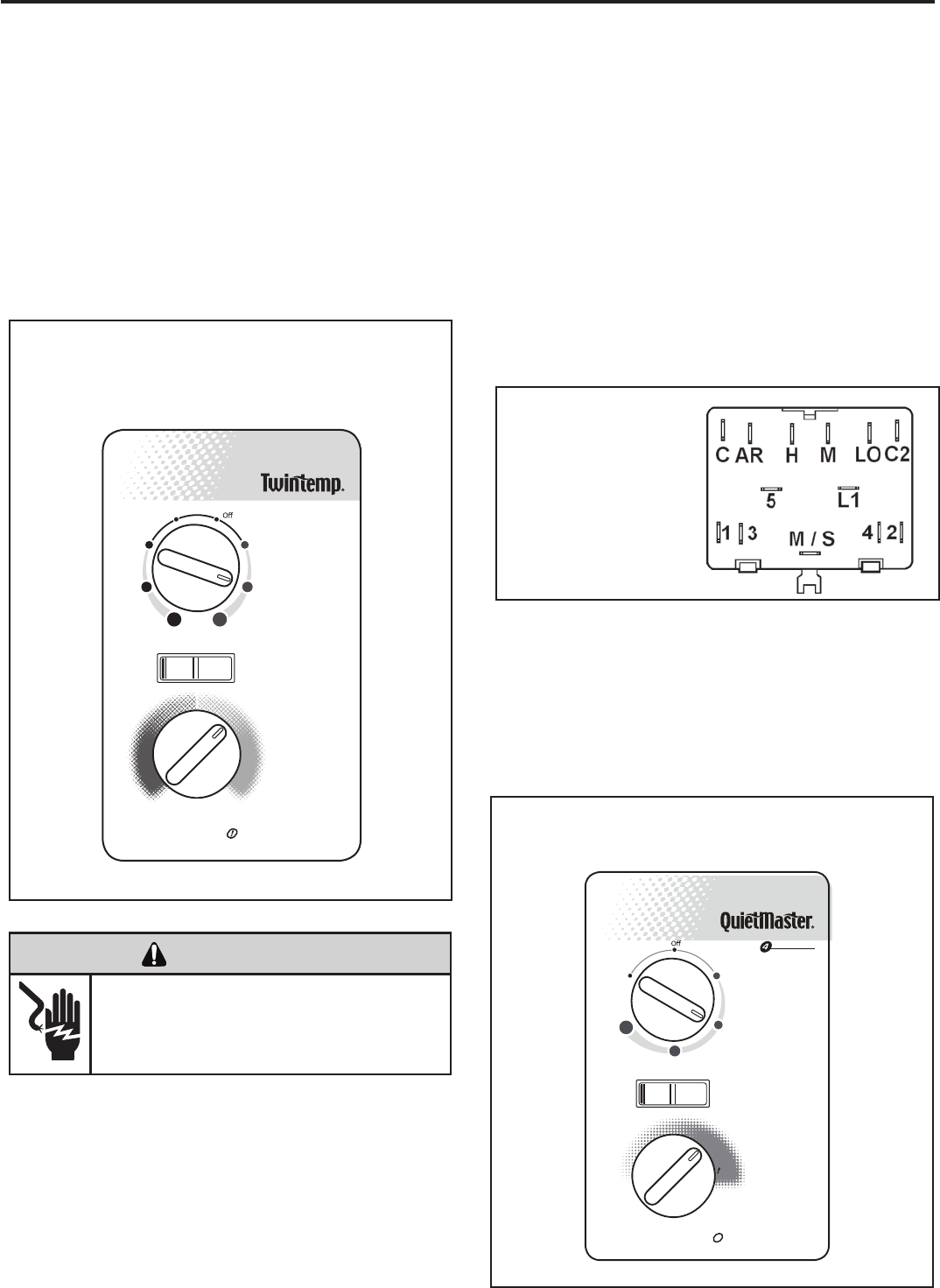
(Heat Pump & Electric Heat Models)
An e ight position control switch i s used t o regulate the
operation of the fan motor and compressor. The compressor
can be operated with the fan operating at low, medium or
high speed in the cooling or heating mode. The fan motor
can also be operated independently on medium speed. See
switch section as indicated on decorative control panel.
NOTE: Heat pump models with electric heat - in the heat
position, heating element only will be energized when
outdoor temperature is below the operating range of the
heat pump.
Figure
Figure
Figure
System Control Panel
Heat Pump & Electric Heat Models
(YS, ES, YM, EM, YL & EL)
SYSTEM CONTROL SWITCH - TEST
Disconnect leads from control switch. Turn control to position
being tested. There must be continuity as follows:
1. “ Off” Position - no continuity between terminals.
2. “ Lo Cool” Position - between terminals “C” and “3”, “C2”
and “2”, “LO” and “M/S”, “AR” and “5”.
3. “ Med Cool” Position - between terminals “C” and “3”,
“C2” and “2”, “M” and “M/S”, “AR” and “5”.
4. “ Hi Cool” Position - between terminals “C” and “3”, “C2”
and “2”, “H” and “M/S”, “AR” and “5”.
System Control Switch
(Heat Pump / Electric
Heat Models
5. “ Hi Heat” Position - between terminals “C” and “1”, “C2”
and “4”, “H” and “M/S”, “AR” and “5”.
6. “ Med Heat” Position - between terminals “C” and “1”,
“C2” and “4”, “M” and “M/S”, “AR” and “5”.
7. “ Lo Cool” Position - between terminals “C” and “1”, “C2”
and “4”, “LO” and “M/S”, “AR” and “5”.
8. “ Fan Only” Position - between terminals “L1” and “M”.
TESTING THE ROTARY CONTROL SWITCHES
Allow 3 min. between restarts
Money Saver
®
MAX
COOL
MAX
HEAT
Low
Cool
Med
Cool
High
Cool
Low
Heat
Med
Heat
High
Heat
Fan
Only
YesNo
KS, KM, SL Models
A six position control switch is used to regulate the operation
of the fan motor and compressor. The compressor can be
operated w ith the fan operating at l ow, medium o r high
speed. The fan motor can also be operated independently
on m edium speed. See switch s ection as indicated on
decorative control panel.
System Control Panel (KS, KM, SL)
Allow3min. betweenrestarts
SPEED
Sleep
Setting
Low
Cool
Medium
Cool
High
Cool
Fan
Only
MINMAX
MoneySaver
®
YesNo
19
12
13
14
(See Figure 14)
(See Figure 13)
(See Figure 12)
ELECTRIC SHOCK HAZARD
WARNING
Disconnect power to the unit before
servicing. Failure to follow this warning
could result in serious injury or death.
20
MECHANICAL COMPONENTS
Bellows condensate valve Temperature-sensitive valve
that opens up to drain off condensate water when the outside
temperature falls below 40°F and closes when the outside
temperature reaches 58°F.
Vent door Allows introduction of fresh air into the room
and/or exhausts stale room air outside (on select models.)
Plenum assembly Diffuser with directional louvers used
to direct the conditioned airfl ow.
Blower wheel Attaches to the indoor side of the fan motor
shaft and is used for distributing unconditioned, room side
air though the heat exchanger and delivering conditioned
air into the room.
Slinger fan blade Attaches to the outdoor side of the fan
motor shaft and is used to move outside air through the
condenser coil, while slinging condensate water out of the
base pan and onto the condenser coil, thus lowering the
temperature and pressures within the coil.
ELECTRICAL COMPONENTS
Thermostat Used to maintain the specifi ed room side
comfort level
System switch Used to regulate the operation of the fan
motor, the compressor or to turn the unit off. For troubleshoot-
ing, refer to the wiring diagrams and schematics in the back
of this service manual.
Capacitor Reduces line current and steadies the voltage
supply, while greatly improving the torque characteristics of
the fan motor and compressor motor.
MoneySaver
Defrost thermostat (Heatpumps only)
® switch When engaged, it sends the power
A dual purpose
supply to the fan motor through the thermostat, which allows
control that acts as an outdoor thermostat and defrost
control.
Smart Fan Automatically adjusts the fan speed to main-
tain the desired room temp.
for a cycle-fan operation.
Fan Motor Dual-shafted fan motor operates the indoor
blower wheel and the condenser fan blade simultaneously.
Solenoid Used to energize the reversing valve on all heat
pump units.
Heating element Electric resistance heater, available in 3.3,
4.0 or 5.2 kW on select TwinTemp® models.
Heat anticipator Used to provide better thermostat and
room air temperature control.
HERMETIC COMPONENTS
Compressor Motorized device used to compress refrigerant
through the sealed system.
Reversing valve A four-way switching device used on all
heat pump models to change the fl ow of refrigerant to permit
heating or cooling.
Check valve A pressure-operated device used to direct the
fl ow of refrigerant to the proper capillary tube, during either
the heating or cooling cycle.
Capillary tube A cylindrical meter device used to evenly dis-
tribute the fl ow of refrigerant to the heat exchangers (coils.)
FUNCTIONAL COMPONENT DEFINITIONS
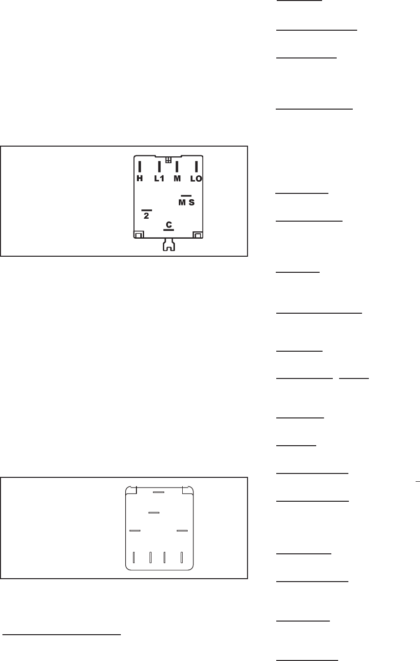
SYSTEM CONTROL SWITCH - TEST (See Figure 15)
Disconnect leads from control switch. There must be
continuity as follows:
1. “Off” Position - no continuity between terminals.
2. “Lo Cool” Position - between terminals “L1” and “C,” “LO”
and “MS.”
3. “Med Cool” Position - between terminals “L1” and “C,” “M”
and “MS.”
4. “Hi Cool” Position - between terminals “L1” and “C,” “H”
and “MS.”
5. “Fan Only” Position - between terminals “L1” and “2.”
Figure 15
System Control Switch
“EQ08” SYSTEM CONTROL SWITCH – TEST
(See Figure 16)
Turn knob to phase of switch to be tested. There must be
continuity as follows:
1. “Fan Only” Position – between terminals “MS” and “H”
2. “Hi Cool” Position – between terminals “L1” and “C” and
“MS” and “H”
3. “Low Cool” Position – between terminals “L1” and “C”
and “MS” and “LO”
4. “Low Heat” Position – between terminals “L2” and “2”
and “MS” and “LO”
5. “Hi Heat” Position – between terminals “L2” and “2” and
“MS” and “H”
L1
MS
2
H
LO
C
L2
B1
Figure 16
System Control Switch
(EQ Models)
COMPONENTS TESTING
21
TEST:
1. Remove leads from thermostat.
2. Turn thermostat knob clockwise to its coldest
position.
3. Test for continuity between the two terminals. Contacts
should be closed.
4. Turn thermostat knob counterclockwise to its warmest
position.
5. Test for continuity - contacts should be open.
NOTE: The thermostat must be within the temperature
range listed to open and close.
To maintain the comfort level desired, a cross ambient type
thermostat is used. The thermostat has a range from 60°
±2°F to 92° ±3°F. The thermostat bulb is positioned in front
of the evaporator coil to sense the return air temperature.
Thermostat malfunction or erratic operation is covered in
the troubleshooting section of this manual.
THERMOSTAT - Models ES, YS, EM, YM, EL, YL
A cross ambient thermostat is used on all heat pump and
electric heat units. In addition to cycling the unit in a heating
or cooling operation, the thermostat will terminate the
cooling cycle in the event ice forms on the evaporator coil,
in this case the thermostat functions as a de-ice control. A
resistor (anticipator) is positioned within a plastic block to
supply a small amount of heat to the bulb area to prevent
long “off cycles” in the “Cool-Fan Auto” (MoneySaver)
position. A current feedback through the fan motor windings
during “off cycle” completes the circuit to the resistor.
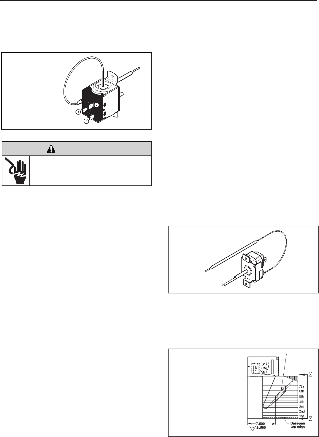
THERMOSTAT (“EQ08” Models)
(See Figure 17)
This thermostat is single pole-double throw, cross ambient
with a range of 60° to 92°F and a differential of ±2°F. Terminal
“2” is common.
Figure 17
Thermostat
(EQ Model)
Figure 18
Thermostat
In the heating cycle, the heat anticipator is energized to
supply a small amount of heat during the “on” cycle. This
will open the contacts in the thermostat prematurely to
maintain a closer differential between the “cut in” and “cut
out” temperature. The heat anticipator is energized in the
heating mode regardless of whether fan is placed in the
automatic (MoneySaver) or constant run position.
RANGE: Thermostat Properties
60°F (±2°) to 92°F (±2°)
TEST:
Cooling/Heating Models: Remove wires from thermostat
and check continuity between terminal “2” (common) and
“3” for cooling. Check between terminals “2” (common)
and “1” for heating. Also check that contacts in thermostat
open after placing in either position. NOTE: Temperature
must be within range listed to check thermostat. Refer to
the troubleshooting section in this manual for additional
information on thermostat testing.
THERMOSTAT ADJUSTMENT
No attempt should be made to adjust thermostat. Due
to the sensitivity of the internal mechanism and the
sophisticated equipment required to check the calibration,
it is suggested that the thermostat be replaced rather than
calibrated. Thermostat bulb must be straight to insure
proper performance.
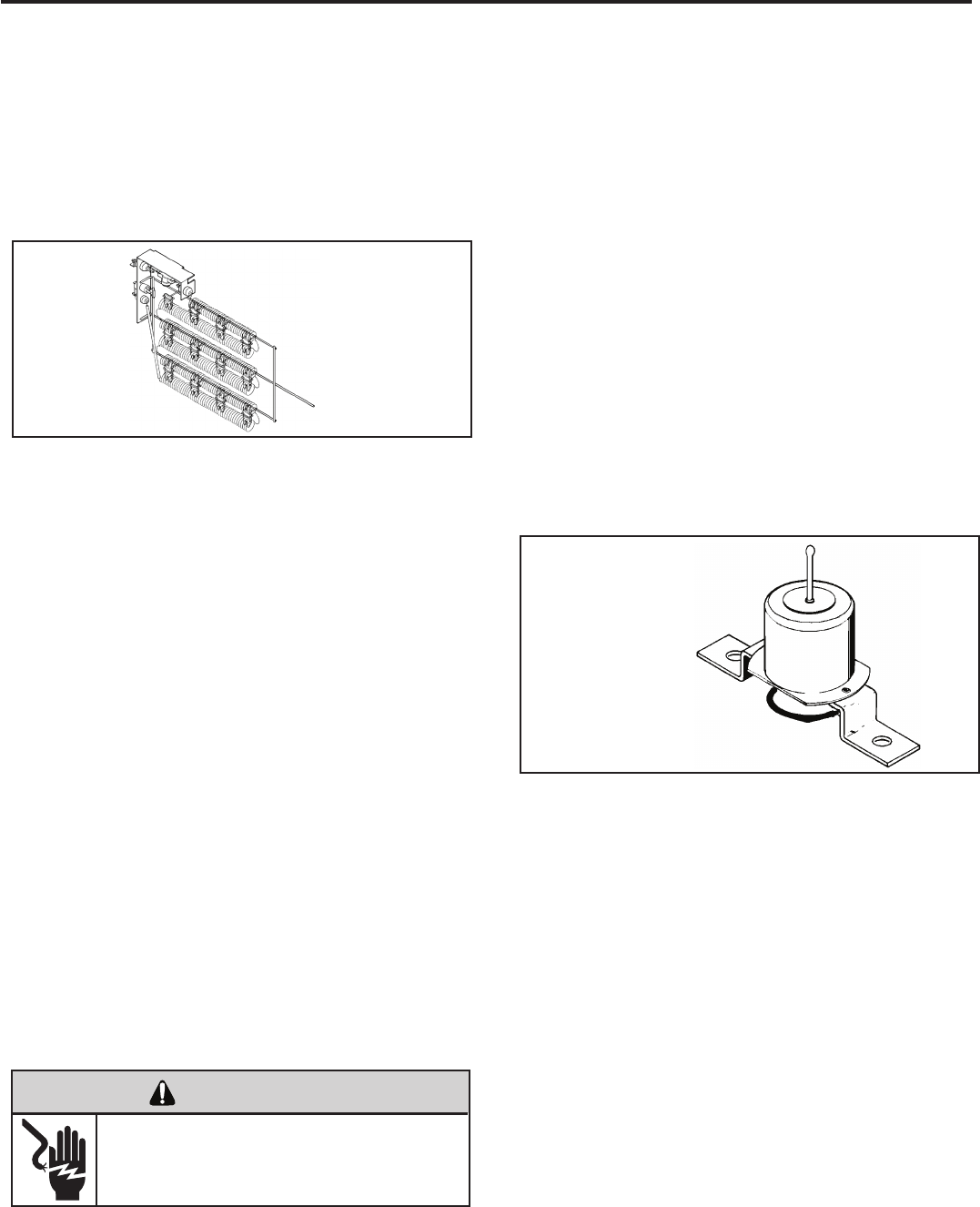
THERMOSTAT BULB LOCATION
The position of the bulb is important in order for the
thermostat to function properly. The bulb of the thermostat
should be located approximately 45° to a maximum of 60°
from horizontal. Also, do not allow the thermostat bulb to
touch the evaporator coil. (See Figures 17 and 18)
Thermostat sensor holder 020
to be positioned between the
4th and 5th and 6th and 7th
rows of tubes from the bottom
of the coil at dimension shown
Figure 19
Thermostat Bulb Location
(EQ Model)
ELECTRIC SHOCK HAZARD
WARNING
Disconnect power to the unit before
servicing. Failure to follow this warning
could result in serious injury or death.
22
COMPONENTS TESTING (Continued)
DEFROST THERMOSTAT (Heat Pump Models Only)
(See Figure 21)
This thermostat is single pole - double throw with contacts
between terminals “2” and “3” closing on temperature rise
and contacts between terminals “2” and “1” closing on
temperature fall. When the contacts between terminals “2”
and “1” make, power is supplied to the heater element.
This control is dual purpose control that acts as an outdoor
thermostat and defrost control.
When the sensing bulb, attached to the outdoor coil,
senses enough icing on the outdoor coil, it will interrupt
power to the compressor and supply power to the heating
element until the coil temperature reaches above 43°, then
the heater will shut off and the unit will resume operating in
the reverse cycle mode.
When the outdoor coil temperature drops below 20°, the
unit will operate in electric heat mode continuously until the
outdoor coil temperature rises above 43°.
The fan motor will not turn off when defrost occurs, and the
4-way valve will not reverse.
Figure 21
Defrost Thermostat
(Heat Pump Models)
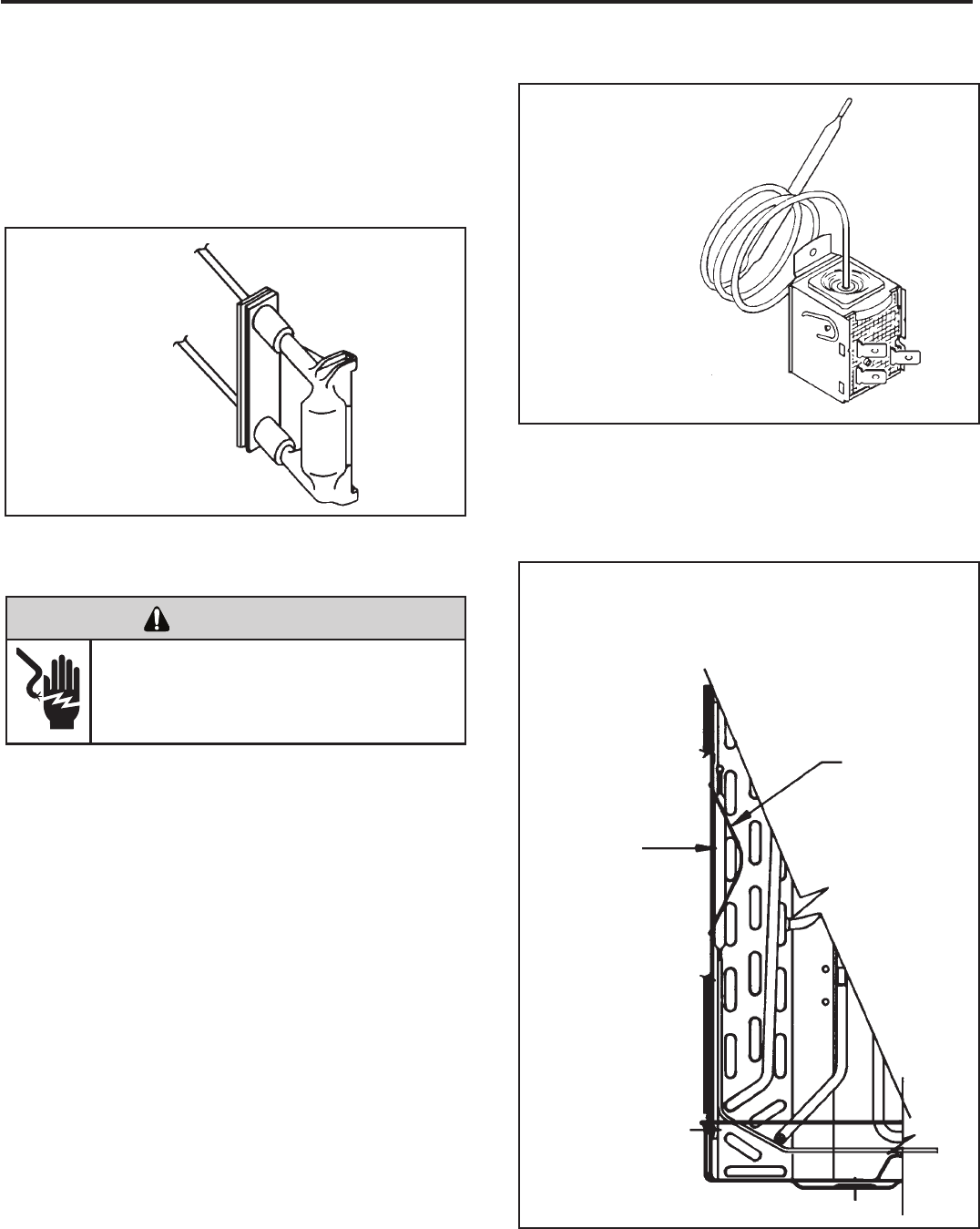
DEFROST BULB LOCATION (Heat Pump Models
Only) (See Figure 22)
The defrost control bulb must be mounted securely and in
the correct location to operate properly.
RESISTOR: Heat Anticipator (See Figure 20)
Failure of the resistor will cause prolonged “off” and “on”
cycles of the unit. When replacing a resistor, be sure and use
the exact replacement. Resistor ratings are as follows:
115 Volt - 5,000 ohms 3 watt
230 Volt - 20,000 ohms 3 watt
Figure 20
Resistor
Slide the bulb
end of the
thermostat
defrost under
the retainer as
shown
Retainer
Figure 22
Defrost Thermostat Bulb
Location (All Heat Pump Models)
ELECTRIC SHOCK HAZARD
WARNING
Disconnect power to the unit before
servicing. Failure to follow this warning
could result in serious injury or death.
23
CAPACITORS
ELECTRIC SHOCK HAZARD
WARNING
Turn off electric power before servicing.
Discharge capacitor with a 20,000 Ohm 2 Watt
resistor before handling.
Failure to do so may result in personal injury,
or death.
Many motor capacitors are internally fused. Shorting the
terminals will blow the fuse, ruining the capacitor. A 20,000
ohm 2 watt resistor can be used to discharge capacitors
safely. Remove wires from capacitor and place resistor
across terminals. When checking a dual capacitor with
a capacitor analyzer or ohmmeter, both sides must be
tested.
Capacitor Check with Capacitor Analyzer
The capacitor analyzer will show whether the capacitor is
“open” or “shorted.” It will tell whether the capacitor is within
its micro farads rating and it will show whether the capacitor
is operating at the proper power-factor percentage. The
instrument will automatically discharge the capacitor when
the test switch is released.
Capacitor Connections
The starting winding of a motor can be damaged by a
shorted and grounded running capacitor. This damage
usually can be avoided by proper connection of the running
capacitor terminals.
From the supply line on a typical 230 volt circuit, a 115 volt
potential exists from the “R” terminal to ground through a
possible short in the capacitor. However, from the “S” or
start terminal, a much higher potential, possibly as high as
400 volts, exists because of the counter EMF generated
in the start winding. Therefore, the possibility of capacitor
failure is much greater when the identied terminal is
connected to the “S” or start terminal. The identied
terminal should always be connected to the supply line, or
“R” terminal, never to the “S” terminal.
When connected properly, a shorted or grounded running
capacitor will result in a direct short to ground from the “R”
terminal and will blow the line fuse. The motor protector
will protect the main winding from excessive temperature.
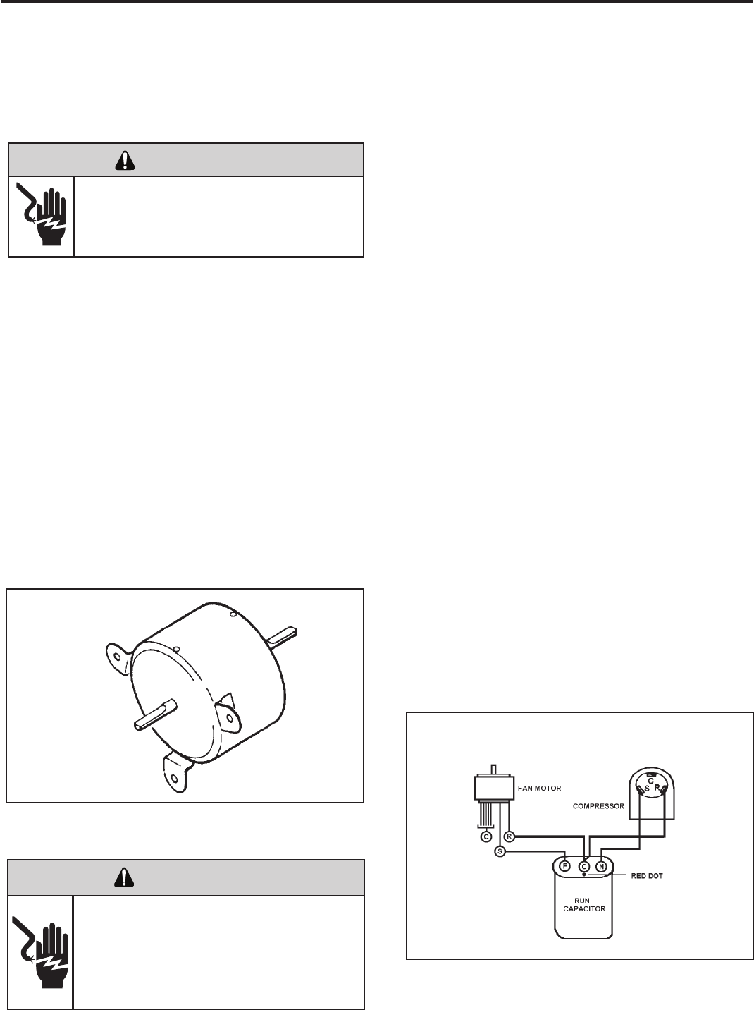
Dual Rated Run Capacitor Hook-up
FIGURE 24
FAN MOTOR - TEST
1. Determine that capacitor is serviceable.
2. Disconnect fan motor wires from fan speed switch or
system switch.
3. Apply “live” test cord probes on black wire and common
terminal of capacitor. Motor should run at high speed.
4. Apply “live” test cord probes on red wire and common
terminal of capacitor. Motor should run at low speed.
5. Apply “live” test cord probes on each of the remaining
wires from the speed switch or system switch to test
intermediate speeds. If the control is in the “MoneySaver”
mode and the thermostat calls for cooling, the fan will
start - then stop after approximately 2 minutes; then the
fan and compressor will start together approximately 2
minutes later.
Figure 23
Fan Motor
FAN MOTOR
A single phase permanent split capacitor motor is used to drive
the evaporator blower and condenser fan. A self-resetting
overload is located inside the motor to protect against high
temperature and high amperage conditions. (See Figure 23)
ELECTRIC SHOCK HAZARD
WARNING
Disconnect power to the unit before
servicing. Failure to follow this warning
could result in serious injury or death.
COMPONENTS TESTING (Continued)
HEATING ELEMENT (See Figure 25)
All heat pumps and electric heat models are equipped with
a heating element with the exception of models starting
with YS09. The “YS” and “ES” models are equipped with a
3.3 KW element. The “YM” and “EM” models are equipped
with a 4.0 KW element. The “YL” and “EL” models are
equipped with a 5.2 KW element. The EQ08 has a 1.15
KW element.
The heating element contains a fuse link and a heater limit
switch. The fuse link is in series with the power supply and
will open and interrupt the power when the temperature
reaches 199°F or a short circuit occurs in the heating
element. Once the fuse link separates, a new fuse link
must be installed.
NOTE: Always replace with the exact replacement.
The heater element has a high limit control. This control
is a bimetal thermostat mounted in the top of the heating
element.
Should the fan motor fail or lter become clogged, the high
limit control will open and interrupt power to the heater
before reaching an unsafe temperature condition.
The control is designed to open at 110°F ±6°F. Test
continuity below 110°F and for open above 110°F.
HEATING ELEMENT (Heat Pump Models)
The heating element for the “Y” model is energized by
an outdoor thermostat. The outdoor defrost thermostat is
adjusted at a predetermined temperature to bring on the
heating element and turn off the compressor. The room
thermostat will then control the cycling of the element when
the selected indoor temperature is reached.
TESTING THE HEATING ELEMENT
Testing of the elements can be made with an ohmmeter
across the terminals after the connecting wires have been
removed. A cold resistance reading of approximately 10.11
ohms for the 1.15 KW heater, 14.5 ohms for the 3.3 KW
heater, 11.9 ohms for the 4.0 KW heater and 9.15 ohms for
the 5.2 KW heater should be registered.
Figure 25
Heating Element
DEFROST THERMOSTAT OPERATION
HEAT PUMP WITH ELECTRIC HEAT:
YS, YM AND YL MODELS
This control is dual purpose control that acts as an outdoor
thermostat and defrost control.
When the sensing bulb, attached to the condenser coil,
senses enough icing on the outdoor coil, it will interrupt
power to the compressor and supply power to the electric
heating element until the coil temperature reaches above
43°, then the electric heater will shut off and the unit will
resume operating in the reverse cycle mode.
When the outdoor coil temperature drops below 20°, the
unit will operate in electric heat mode continuously until
the outdoor coil temperature rises above 43°.
The fan motor will not turn off when defrost occurs, and
the 4-way valve will not reverse.
DRAIN PAN VALVE
(See Figure 26)
During the cooling mode of operation, condensate which
collects in the drain pan is picked up by the condenser fan
blade and sprayed onto the condenser coil. This assists
in cooling the refrigerant plus evaporating the water.
During the heating mode of operation, it is necessary that
water be removed to prevent it from freezing during cold
outside temperatures. This could cause the condenser
fan blade to freeze in the accumulated water and prevent
it from turning.
To provide a means of draining this water, a bellows type
drain valve is installed over a drain opening in the base
pan.
This valve is temperature sensitive and will open when
the outside temperature reaches 40°F. The valve will
close gradually as the temperature rises above 40°F to
fully close at 60°F.
Figure 26
Bellows Assembly
Drain Pan Valve
24
COMPONENTS TESTING (Continued)
ELECTRIC SHOCK HAZARD
WARNING
Disconnect power to the unit before
servicing. Failure to follow this warning
could result in serious injury or death.

Mode Control
The mode control pad(s) allow the selection of the operating
modes of the unit.
There is a two second delay before the mode activates its
appropriate relay.
OPERATING SEQUENCE / CHARACTERISTICS
AND FEATURES
Compressor Operation
The run state of the compressor is determined by the
difference between the indoor ambient temperature and
the set temperature. See specic mode of operation for
details.
Compressor Time Delay: 180 seconds
This feature is initiated every time the compressor is de-
energized, either due to:
(1) satisfying the temperature set point
(2) changing mode to fan only
(3) a power interruption or
(4) turning the unit off
The compressor is also time delayed for 3 minutes when the
control is rst plugged in or power is restored after failure.
When the compressor cycles off as a result of satisfying the
“load”, the time delay is typically timed out during the off
cycle. Compressor time delay is bypassed by “Test Mode”.
Return Air Temperature Sensor
The control range is 60°F to 90°F +/- 2.0°F.
Frost Protection Sensor
Temperature settings:
Disable the compressor when sensing 30 +/- 3°F for 2 min.
continuously.
Enable compressor @ 55 +/- 5°F.
The fan should not be affected by the Frost Protection. It
should continue to function normally if freeze protection is
called for.
COOL Mode for SS, SM and XQ Models
When in the COOL mode, the control will turn on the
compressor when the indoor temperature is 1.5°F above the
set point and turn off the compressor when the ambient gets
below the set point by 1.5°F. The fan will run continuously.
MONEY SAVER Mode
When in MONEY SAVER mode, the system will be turned
on when the indoor temperature gets above the set point
by 0.75°F and turns off when the indoor temperature gets
below the set point by 0.75°F. The fan will turn on 5 seconds
before the compressor and turn off 5 seconds after the
compressor stops. If the compressor is delayed the fan
will continue to run while the compressor restarts. If the
ELECTRONIC CONTROL SEQUENCE OF OPERATION
QME AND XQ MODELS
thermostat remains satised for more than approximately 9
minutes, the fan will turn on for a period of 90 seconds for
air sampling. Operation in MONEY SAVER mode will light
both the MONEY SAVER and COOL indicators.
FAN ONLY Mode
When in the FAN ONLY mode, the compressor will not
operate. The fan will run continuously at the user-selected
speed (see “Fan Speed Set” below). Smart Fan is not
available in FAN ONLY Mode.
Fan Speed Set
SS/SM fan speed is changed by pressing SPEED 1-4
pad and scrolling through F1, F2, F3, and F4 in the digital
display.
XQ fan speed is changed by pressing FAN SPEED pad
and scrolling through F1, F2, F3 and SF (Smart Fan) in the
digital display.
There will be a 2 second delay before the fan speed changes
to prevent unnecessary switching of the relays during fan
speed selection.
SMART FAN
On the SS/SM models, smart fan is activated by pressing
the SMART FAN button. On the XQ model, smart fan is
activated by pressing the FAN SPEED button and scrolling
through speeds until “SF” appears in the digital display.
Using the remote control, Smart Fan is selected by the
fourth push of Fan Speed button.
Smart fan changes fan speeds based on the temperature
differential between the ambient and set temperatures.
25
PROGRAMMABLE
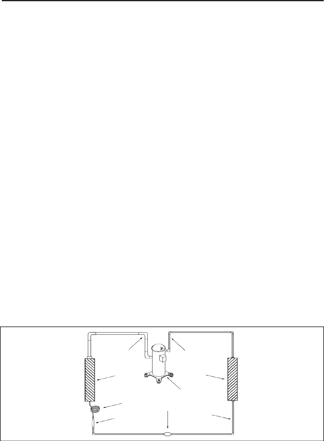
Suction
Line
Evaporator
Coil
Metering
Device
Refrigerant
Strainer
Discharge
Line
Condenser
Coil
Compressor
Refrigerant Drier Liquid
Line
A good understanding of the basic operation of the
refrigeration system is essential for the service technician.
Without this understanding, accurate troubleshooting of
refrigeration system problems will be more difcult and time
consuming, if not (in some cases) entirely impossible. The
refrigeration system uses four basic principles (laws) in its
operation they are as follows:
1. “Heat always ows from a warmer body to a cooler
body.”
2. “Heat must be added to or removed from a substance
before a change in state can occur”
3. “Flow is always from a higher pressure area to a lower
pressure area.”
4. “The temperature at which a liquid or gas changes state
is dependent upon the pressure.”
The refrigeration cycle begins at the compressor. Starting
the compressor creates a low pressure in the suction line
which draws refrigerant gas (vapor) into the compressor.
The compressor then “compresses” this refrigerant, raising
its pressure and its (heat intensity) temperature.
The refrigerant leaves the compressor through the discharge
Line as a hot High pressure gas (vapor). The refrigerant
enters the condenser coil where it gives up some of its
heat. The condenser fan moving air across the coil’s nned
surface facilitates the transfer of heat from the refrigerant to
the relatively cooler outdoor air.
When a sufcient quantity of heat has been removed from
the refrigerant gas (vapor), the refrigerant will “condense”
(i.e. change to a liquid). Once the refrigerant has been
condensed (changed) to a liquid it is cooled even further by
the air that continues to ow across the condenser coil.
The RAC design determines at exactly what point (in the
condenser) the change of state (i.e. gas to a liquid) takes
place. In all cases, however, the refrigerant must be
totally condensed (changed) to a Liquid before leaving the
condenser coil.
The refrigerant leaves the condenser Coil through the liquid
line as a warm high pressure liquid. It next will pass through
the refrigerant drier (if so equipped). It is the function of the
drier to trap any moisture present in the system, contaminants,
and large particulate matter.
The liquid refrigerant next enters the metering device. The
metering device is a capillary tube. The purpose of the
metering device is to “meter” (i.e. control or measure) the
quantity of refrigerant entering the evaporator coil.
In the case of the capillary tube this is accomplished (by
design) through size (and length) of device, and the pressure
difference present across the device.
Since the evaporator coil is under a lower pressure (due to
the suction created by the compressor) than the liquid line,
the liquid refrigerant leaves the metering device entering the
evaporator coil. As it enters the evaporator coil, the larger
area and lower pressure allows the refrigerant to expand
and lower its temperature (heat intensity). This expansion is
often referred to as “boiling”. Since the unit’s blower is moving
indoor air across the nned surface of the evaporator coil,
the expanding refrigerant absorbs some of that heat. This
results in a lowering of the indoor air temperature, hence the
“cooling” effect.
The expansion and absorbing of heat cause the liquid
refrigerant to evaporate (i.e. change to a gas). Once the
refrigerant has been evaporated (changed to a gas), it is
heated even further by the air that continues to ow across
the evaporator coil.
The particular system design determines at exactly what
point (in the evaporator) the change of state (i.e. liquid to a
gas) takes place. In all cases, however, the refrigerant must
be totally evaporated (changed) to a gas before leaving the
evaporator coil.
The low pressure (suction) created by the compressor
causes the refrigerant to leave the evaporator through the
suction line as a cool low pressure vapor. The refrigerant then
returns to the compressor, where the cycle is repeated.
REFRIGERATION SEQUENCE OF OPERATION
26
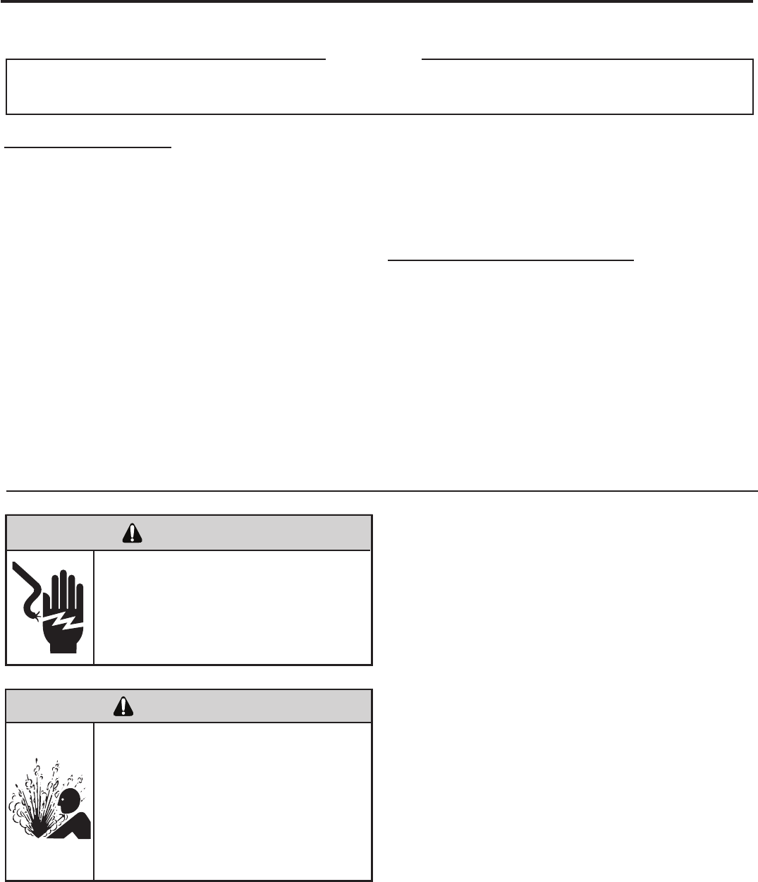
Refrigerant Charging
NOTE: Because The RAC System Is A Sealed System,
Service Process Tubes Will Have To Be Installed. First
Install A Line Tap And Remove Refrigerant From System.
Make Necessary Sealed System Repairs And Vacuum
System. Crimp Process Tube Line And Solder End Shut.
Do Not Leave A Service Valve In The Sealed System.
Proper refrigerant charge is essential to proper unit
operation. Operating a unit with an improper refrigerant
charge will result in reduced performance (capacity) and/or
efciency. Accordingly, the use of proper charging methods
during servicing will insure that the unit is functioning as
designed and that its compressor will not be damaged.
Too much refrigerant (overcharge) in the system is just as bad
(if not worse) than not enough refrigerant (undercharge). They
both can be the source of certain compressor failures if they
remain uncorrected for any period of time. Quite often, other
problems (such as low air ow across evaporator, etc.) are
misdiagnosed as refrigerant charge problems. The refrigerant
circuit diagnosis chart will assist you in properly diagnosing
these systems.
An overcharged unit will at times return liquid refrigerant
(slugging) back to the suction side of the compressor eventually
causing a mechanical failure within the compressor. This
mechanical failure can manifest itself as valve failure, bearing
failure, and/or other mechanical failure. The specic type of
failure will be inuenced by the amount of liquid being returned,
and the length of time the slugging continues.
Not enough refrigerant (undercharge) on the other hand, will
cause the temperature of the suction gas to increase to the point
where it does not provide sufcient cooling for the compressor
motor. When this occurs, the motor winding temperature will
increase causing the motor to overheat and possibly cycle open
the compressor overload protector. Continued overheating of
the motor windings and/or cycling of the overload will eventually
lead to compressor motor or overload failure.
Unplug and/or disconnect all electrical power
to the unit before performing inspections,
maintenances or service.
Failure to do so could result in electric shock,
serious injury or death.
Sealed Refrigeration System contains refrigerant
and oil under high pressure.
Proper safety procedures must be followed,
and proper protective clothing must be worn
when working with refrigerants.
Failure to follow these procedures could
result in serious injury or death.
WARNING
WARNING
RISK OF ELECTRIC SHOCK
HIGH PRESSURE HAZARD
SEALED REFRIGERATION SYSTEM REPAIRS
ANY SEALED SYSTEM REPAIRS TO COOL-ONLY MODELS REQUIRE THE INSTALLATION OF A LIQUID LINE DRIER.
ALSO, ANY SEALED SYSTEM REPAIRS TO HEAT PUMP MODELS REQUIRE THE INSTALLATION OF A SUCTION LINE DRIER.
IMPORTANT
EQUIPMENT REQUIRED:
1. Voltmeter
2. Ammeter
3. Ohmmeter
4. E.P.A. Approved Refrigerant Recovery System
5. Vacuum Pump (capable of 200 microns or less
vacuum.)
6. Acetylene Welder
7. Electronic Halogen Leak Detector (G.E. Type H-6 or
equivalent.)
8. Accurate refrigerant charge measuring device such
as:
a. Balance Scales - 1/2 oz. accuracy
b. Charging Board - 1/2 oz. accuracy
9. High Pressure Gauge - (0 - 400 lbs.)
10. Low Pressure Gauge - (30 - 150 lbs.)
11. Vacuum Gauge - (0 - 1000 microns)
EQUIPMENT MUST BE CAPABLE OF:
1. Recovery CFC’s as low as 5%.
2. Evacuation from both the high side and low side of the
system simultaneously.
3. Introducing refrigerant charge into high side of the
system.
4. Accurately weighing the refrigerant charge actually
introduced into the system.
5. Facilities for owing nitrogen through refrigeration tubing
during all brazing processes.
27
3. Install a process tube to sealed system.
4. Make necessary repairs to system.
5. Evacuate system to 200 microns or less.
6. Weigh in refrigerant with the property quantity of R-22
refrigerant.
7. Start unit, and verify performance.
8. Crimp the process tube and solder the end shut.
Proper safety procedures must be followed,
and proper protective clothing must be worn
when working with a torch.
Failure to follow these procedures could
result in moderate or serious injury.
Proper safety procedures must be followed,
and proper protective clothing must be worn
when working with liquid refrigerant.
Failure to follow these procedures could
result in minor to moderate injury.
WARNING
CAUTION
BURN HAZARD
FREEZE HAZARD
Proper safety procedures must be followed,
and proper protective clothing must be worn
when working with a torch.
Failure to follow these procedures could
result in moderate or serious injury.
WARNING
BURN HAZARD
Method Of Charging / Repairs
The acceptable method for charging the RAC system is the
Weighed in Charge Method. The weighed in charge method is
applicable to all units. It is the preferred method to use, as it is
the most accurate.
The weighed in method should always be used whenever
a charge is removed from a unit such as for a leak repair,
compressor replacement, or when there is no refrigerant
charge left in the unit. To charge by this method, requires the
following steps:
1. Install a piercing valve to remove refrigerant from the
sealedsystem. (Piercing valve must be removed from the
system before recharging.)
2. Recover Refrigerant in accordance with EPA regulations.
28
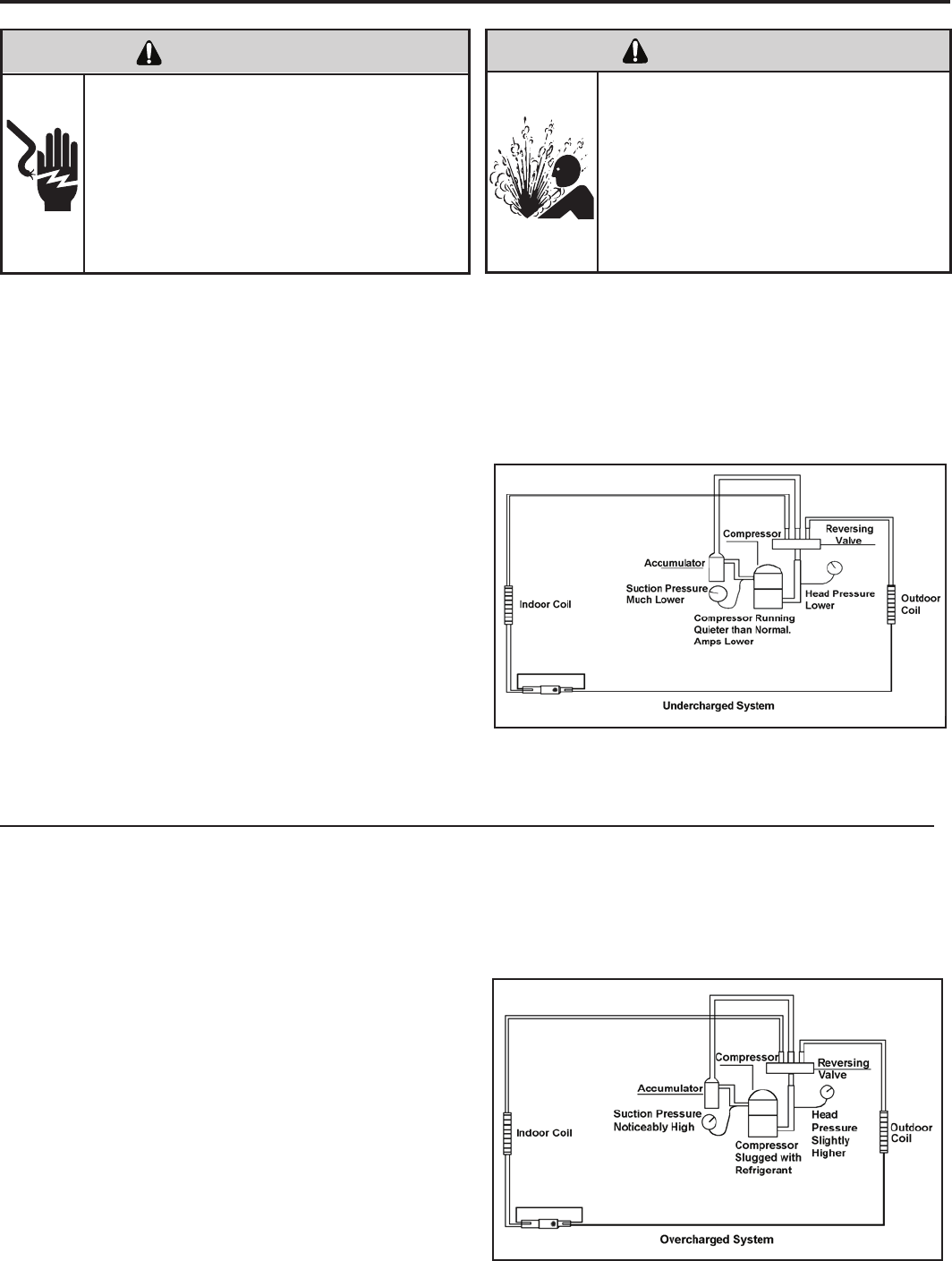
Undercharged Refrigerant Systems
An undercharged system will result in poor performance
(low pressures, etc.) in both the heating and cooling
cycle.
Whenever you service a unit with an undercharge of
refrigerant, always suspect a leak. The leak must be
repaired before charging the unit.
To check for an undercharged system, turn the unit on,
allow the compressor to run long enough to establish
working pressures in the system (15 to 20 minutes).
During the cooling cycle you can listen carefully at the exit
of the metering device into the evaporator; an intermittent
hissing and gurgling sound indicates a low refrigerant
charge. Intermittent frosting and thawing of the evaporator
is another indication of a low charge, however, frosting
and thawing can also be caused by insufcient air over
the evaporator.
Checks for an undercharged system can be made at
the compressor. If the compressor seems quieter than
normal, it is an indication of a low refrigerant charge.
Overcharged Refrigerant Systems
A check of the amperage drawn by the compressor
motor should show a lower reading. (Check the Unit
Specication.) After the unit has run 10 to 15 minutes,
check the gauge pressures. Gauges connected to system
with an undercharge will have low head pressures and
substantially low suction pressures.
of the evaporator will not be encountered because the
refrigerant will boil later if at all. Gauges connected to
system will usually have higher head pressure (depending
upon amount of over charge). Suction pressure should be
slightly higher.
Compressor amps will be near normal or higher.
Noncondensables can also cause these symptoms. To
conrm, remove some of the charge, if conditions improve,
system may be overcharged. If conditions don’t improve,
Noncondensables are indicated.
Whenever an overcharged system is indicated, always
make sure that the problem is not caused by air ow
problems. Improper air ow over the evaporator coil may
indicate some of the same symptoms as an over charged
system.
An overcharge can cause the compressor to fail, since it
would be “slugged” with liquid refrigerant.
The charge for any system is critical. When the compressor
is noisy, suspect an overcharge, when you are sure that
the air quantity over the evaporator coil is correct. Icing
ELECTRIC SHOCK HAZARD
WARNING
Turn off electric power before service or
installation.
Extreme care must be used, if it becomes
necessary to work on equipment with power
applied.
Failure to do so could result in serious injury or
death.
Sealed Refrigeration System contains refrigerant
and oil under high pressure.
Proper safety procedures must be followed,
and proper protective clothing must be worn
when working with refrigerants.
Failure to follow these procedures could
result in serious injury or death.
WARNING
HIGH PRESSURE HAZARD
29
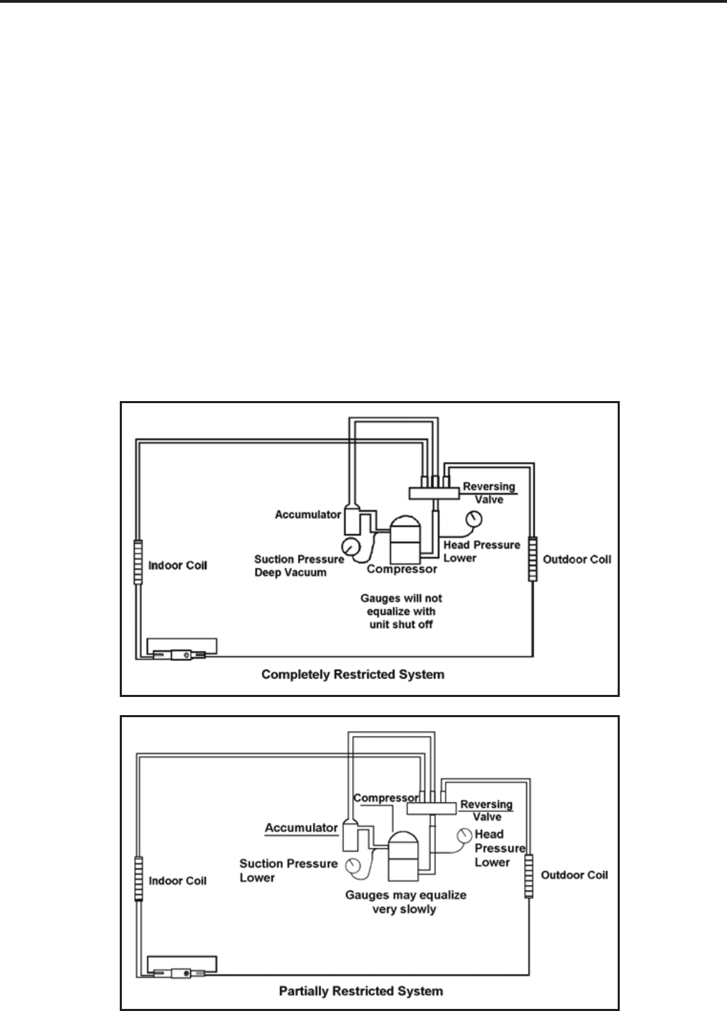
Restricted Refrigerant System
Troubleshooting a restricted refrigerant system can be
difcult. The following procedures are the more common
problems and solutions to these problems. There are two
types of refrigerant restrictions: Partial restrictions and
complete restrictions.
A partial restriction allows some of the refrigerant to
circulate through the system.
With a complete restriction there is no circulation of
refrigerant in the system.
Restricted refrigerant systems display the same symptoms
as a “low-charge condition.”
When the unit is shut off, the gauges may equalize very
slowly.
Gauges connected to a completely restricted system will
run in a deep vacuum. When the unit is shut off, the gauges
will not equalize at all.
A quick check for either condition begins at the evaporator.
With a partial restriction, there may be gurgling sounds
at the metering device entrance to the evaporator. The
evaporator in a partial restriction could be partially frosted
or have an ice ball close to the entrance of the metering
device. Frost may continue on the suction line back to the
compressor.
Often a partial restriction of any type can be found by feel,
as there is a temperature difference from one side of the
restriction to the other.
With a complete restriction, there will be no sound at the
metering device entrance. An amperage check of the
compressor with a partial restriction may show normal
current when compared to the unit speci cation. With a
complete restriction the current drawn may be considerably
less than normal, as the compressor is running in a deep
vacuum (no load.) Much of the area of the condenser will
be relatively cool since most or all of the liquid refrigerant
will be stored there.
The following conditions are based primarily on a system
in the cooling mode.
30
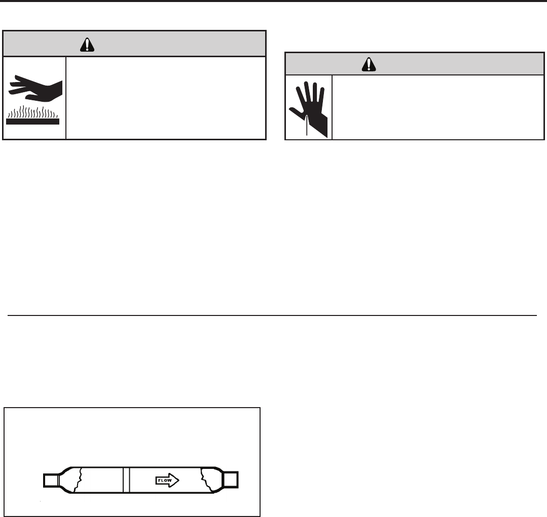
METERING DEVICE
Capillary Tube Systems
All units are equipped with capillary tube metering
devices.
Checking for restricted capillary tubes.
1. Connect pressure gauges to unit.
2. Start the unit in the cooling mode. If after a few minutes
of operation the pressures are normal, the check valve
and the cooling capillary are not restricted.
3. Switch the unit to the heating mode and observe the
gauge readings after a few minutes running time. If
the system pressure is lower than normal, the heating
capillary is restricted.
4. If the operating pressures are lower than normal in both
the heating and cooling mode, the cooling capillary is
restricted.
Proper safety procedures must be followed,
and proper protective clothing must be worn
when working with a torch.
Failure to follow these procedures could
result in moderate or serious injury.
WARNING
BURN HAZARD
HERMETIC COMPONENTS CHECK
One-way Check Valve
(Heat Pump Models)
CHECK VALVE
A unique two-way check valve is used on the reverse cycle
heat pumps. It is pressure operated and used to direct the
ow of refrigerant through a single lter drier and to the
proper capillary tube during either the heating or cooling
cycle.
NOTE: The slide (check) inside the valve is made of teon.
Should it become necessary to replace the check valve,
place a wet cloth around the valve to prevent overheating
during the brazing operation.
CHECK VALVE OPERATION
In the cooling mode of operation, high pressure liquid enters
the check valve forcing the slide to close the opposite port
(liquid line) to the indoor coil. Refer to refrigerant ow chart.
This directs the refrigerant through the lter drier and cooling
capillary tube to the indoor coil.
In the heating mode of operation, high pressure refrigerant
enters the check valve from the opposite direction, closing
the port (liquid line) to the outdoor coil. The ow path of the
refrigerant is then through the lter drier and heating capillary
to the outdoor coil.
Failure of the slide in the check valve to seat properly in
either mode of operation will cause ooding of the cooling
coil. This is due to the refrigerant bypassing the heating or
cooling capillary tube and entering the liquid line.
COOLING MODE
In the cooling mode of operation, liquid refrigerant from
condenser (liquid line) enters the cooling check valve
forcing the heating check valve shut. The liquid refrigerant
is directed into the liquid dryer after which the refrigerant
is metered through cooling capillary tubes to evaporator.
(Note: liquid refrigerant will also be directed through the
heating capillary tubes in a continuous loop during the
cooling mode).
HEATING MODE
In the heating mode of operation, liquid refrigerant from
the indoor coil enters the heating check valve forcing the
cooling check valve shut. The liquid refrigerant is directed
into the liquid dryer after which the refrigerant is metered
through the heating capillary tubes to outdoor coils. (Note:
liquid refrigerant will also be directed through the cooling
capillary tubes in a continuous loop during the heating
mode).
31
CUT/SEVER HAZARD
WARNING
Be careful with the sharp edges and corners.
Wear protective clothing and gloves, etc.
Failure to do so could result in serious injury.
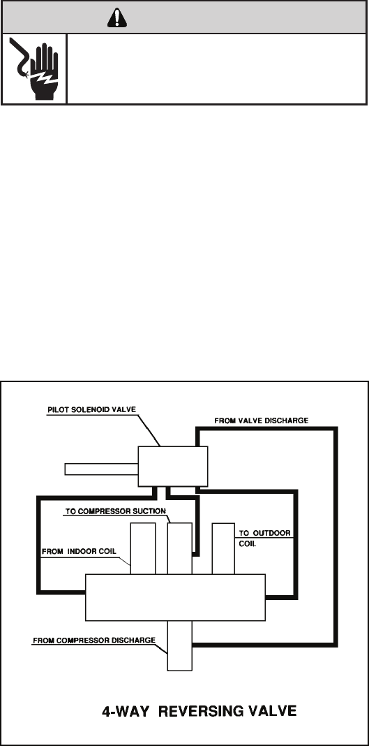
NOTE: System operating pressures must be near
normal before valve can shift.
REVERSING VALVE DESCRIPTION/OPERATION
The Reversing Valve controls the direction of refrigerant
ow to the indoor and outdoor coils. It consists of a
pressure-operated, main valve and a pilot valve actuated
by a solenoid plunger. The solenoid is energized during the
heating cycle only. The reversing valves used in the RAC
system is a 2-position, 4-way valve.
The single tube on one side of the main valve body is the
high-pressure inlet to the valve from the compressor. The
center tube on the opposite side is connected to the low
pressure (suction) side of the system. The other two are
connected to the indoor and outdoor coils. Small capillary
tubes connect each end of the main valve cylinder to the
“A” and “B” ports of the pilot valve. A third capillary is a common
return line from these ports to the suction tube on the main
valve body. Four-way reversing valves also have a capillary
tube from the compressor discharge tube to the pilot valve.
The piston assembly in the main valve can only be shifted
by the pressure differential between the high and low sides
of the system. The pilot section of the valve opens and
closes ports for the small capillary tubes to the main valve
to cause it to shift.
ELECTRIC SHOCK HAZARD
WARNING
Disconnect power to the unit before servicing.
Failure to follow this warning could result in
serious injury or death.
32
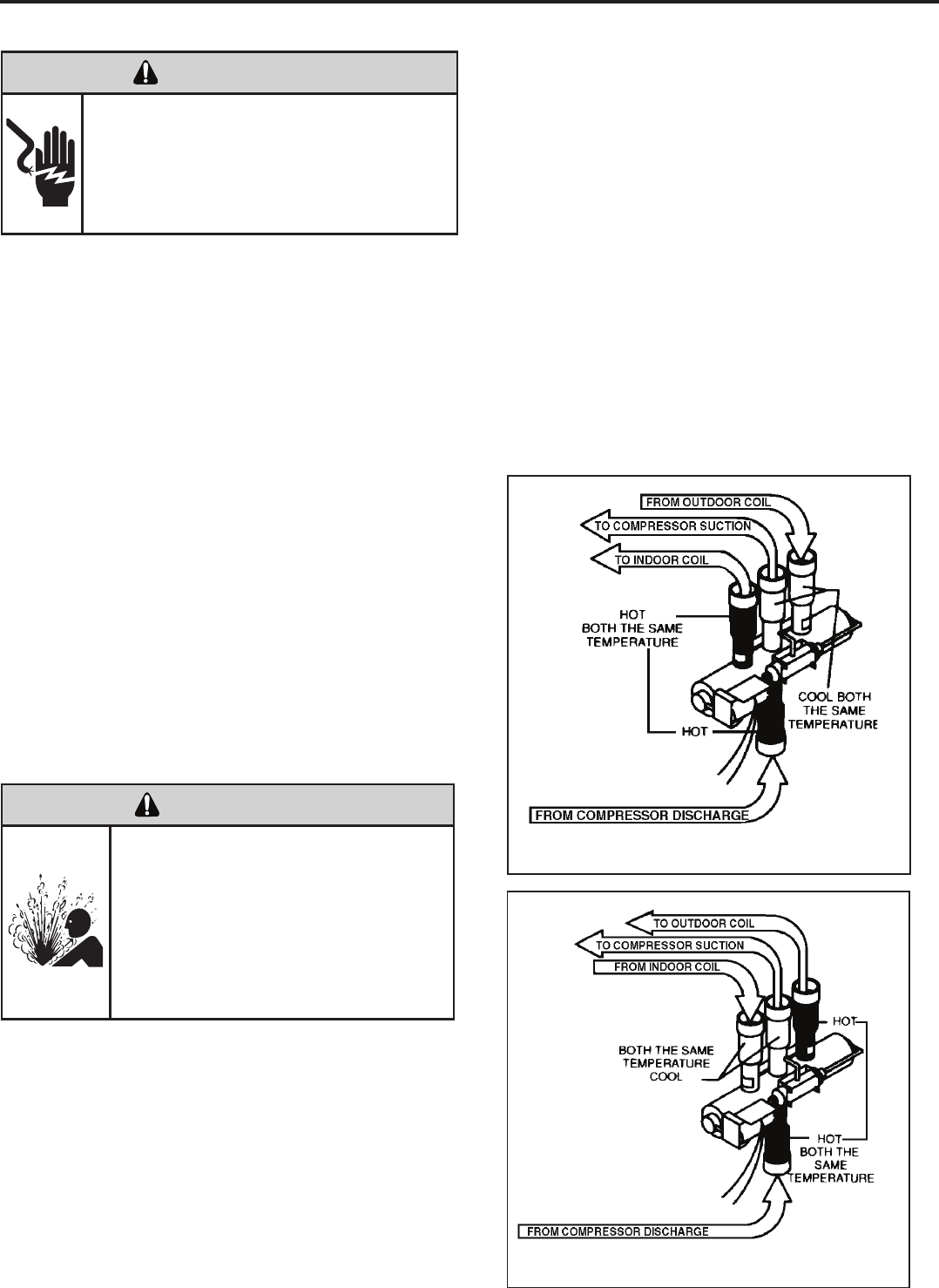
Reversing Valve in Heating Mode
TESTING THE COIL
The solenoid coil is an electromagnetic type coil mounted
on the reversing valve and is energized during the
operation of the compressor in the heating cycle.
1. Turn off high voltage electrical power to unit.
2. Unplug line voltage lead from reversing valve coil.
3. Check for electrical continuity through the coil. If you
do not have continuity replace the coil.
4. Check from each lead of coil to the copper liquid line
as it leaves the unit or the ground lug. There should
be no continuity between either of the coil leads
and ground; if there is, coil is grounded and must be
replaced.
5. If coil tests okay, reconnect the electrical leads.
6. Make sure coil has been assembled correctly.
NOTE: Do not start unit with solenoid coil removed from
valve, or do not remove coil after unit is in operation. This
will cause the coil to burn out.
CHECKING THE REVERSING VALVE
NOTE: You must have normal operating pressures before
the reversing valve can shift.
Check the operation of the valve by starting the system
and switching the operation from “Cooling” to “Heating”
and then back to “Cooling”. Do not hammer on valve.
Occasionally, the reversing valve may stick in the heating
or cooling position or in the mid-position.
When sluggish or stuck in the mid-position, part of the
discharge gas from the compressor is directed back to the
suction side, resulting in excessively high suction pressure.
Should the valve fail to shift from coooling to heating, block
the air ow through the outdoor coil and allow the discharge Reversing Valve in Cooling Mode
ELECTRIC SHOCK HAZARD
WARNING
Unplug and/or disconnect all electrical power
to the unit before performing inspections,
maintenances or service.
Failure to do so could result in electric shock,
serious injury or death.
Sealed Refrigeration System contains refrigerant
and oil under high pressure.
Proper safety procedures must be followed,
and proper protective clothing must be worn
when working with refrigerants.
Failure to follow these procedures could
result in serious injury or death.
WARNING
HIGH PRESSURE HAZARD
pressure to build in the system. Then switch the system
from heating to cooling.
If the valve is stuck in the heating position, block the air
ow through the indoor coil and allow discharge pressure
to build in the system. Then switch the system from
heating to cooling.
Should the valve fail to shift in either position after
increasing the discharge pressure, replace the valve.
Dented or damaged valve body or capillary tubes can
prevent the main slide in the valve body from shifting.
If you determing this is the problem, replace the reversing
valve.
After all of the previous inspections and checks have
been made and determined correct, then perform the
“Touch Test” on the reversing valve.
33
8. Pressurize sealed system with a combination of R-22
and nitrogen and check for leaks, using a suitable leak
detector. Recover refrigerant per EPA guidelines.
9. Once the sealed system is leak free, install solenoid coil
on new valve and charge the sealed system by weighing
in the proper amount and type of refrigerant as shown
on rating plate. Crimp the process tubes and solder the
ends shut. Do not leave Schrader or piercing valves in
the sealed system.
NOTE: When brazing a reversing valve into the system, it is
of extreme importance that the temperature of the valve does
not exceed 250°F at any time.
Wrap the reversing valve with a large rag saturated with
water. “Re-wet” the rag and thoroughly cool the valve after
each brazing operation of the four joints involved.
The wet rag around the reversing valve will eliminate
conduction of heat to the valve body when brazing the line
connection.
6. Protect new valve body from heat while brazing with plastic
heat sink (Thermo Trap) or wrap valve body with wet
rag.
7. Fit all lines into new valve and braze lines into new
valve.
Procedure For Changing Reversing Valve
1. Install Process Tubes. Recover refrigerant from sealed
system. PROPER HANDLING OF RECOVERED
REFRIGERANT ACCORDING TO EPA REGULATIONS
IS REQUIRED.
2. Remove solenoid coil from reversing valve. If coil is to
be reused, protect from heat while changing valve.
3. Unbraze all lines from reversing valve.
4. Clean all excess braze from all tubing so that they will
slip into ttings on new valve.
5. Remove solenoid coil from new valve.
The use of a torch requires extreme care and proper
judgment. Follow all safety recommended precautions
and protect surrounding areas with re proof materials.
Have a re extinguisher readily available. Failure to follow
this notice could result in moderate to serious property
damage.
NOTICE
FIRE HAZARD
Touch Test in Heating/Cooling Cycle
The only definite indications that the slide is in the mid-
position is if all three tubes on the suction side of the valve
are hot after a few minutes of running time.
NOTE: A condition other than those illustrated above, and
on Page 31, indicate that the reversing valve is not shifting
properly. Both tubes shown as hot or cool must be the same
corresponding temperature.
Certain unit components operate at
temperatures hot enough to cause burns.
Proper safety procedures must be followed,
and proper protective clothing must be
worn.
Failure to follow these procedures could
result in minor to moderate injury.
WARNING
BURN HAZARD
Sealed Refrigeration System contains refrigerant
and oil under high pressure.
Proper safety procedures must be followed,
and proper protective clothing must be worn
when working with refrigerants.
Failure to follow these procedures could
result in serious injury or death.
WARNING
HIGH PRESSURE HAZARD
The use of nitrogen requires a pressure
regulator. Follow all safety procedures and
wear protective safety clothing etc.
Failure to follow proper safety procedures
could result in serious injury or death.
WARNING
EXPLOSION HAZARD
34
Locked Rotor Voltage (L.R.V.) Test
Locked rotor voltage (L.R.V.) is the actual voltage available
at the compressor under a stalled condition.
Single Phase Connections
Disconnect power from unit. Using a voltmeter, attach one
lead of the meter to the run “R” terminal on the compressor
and the other lead to the common “C” terminal of the com-
pressor. Restore power to unit.
Determine L.R.V.
Start the compressor with the volt meter attached; then stop
the unit. Attempt to restart the compressor within a couple
of seconds and immediately read the voltage on the meter.
The compressor under these conditions will not start and will
usually kick out on overload within a few seconds since the
pressures in the system will not have had time to equalize.
Voltage should be at or above minimum voltage of 197 VAC,
as specied on the rating plate. If less than minimum, check
for cause of inadequate power supply; i.e., incorrect wire
size, loose electrical connections, etc.
COMPRESSOR CHECKS
ELECTRIC SHOCK HAZARD
WARNING
Turn off electric power before service or
installation. Extreme care must be used, if it
becomes necessary to work on equipment with
power applied.
Failure to do so could result in serious injury or
death.
External Overload
The compressor is equipped with an external overload
which senses both motor amperage and winding tem-
perature. High motor temperature or amperage heats the
overload causing it to open, breaking the common circuit
within the compressor.
Heat generated within the compressor shell, usually due
to recycling of the motor, is slow to dissipate. It may take
anywhere from a few minutes to several hours for the
overload to reset.
Checking the External Overload
With power off, remove the leads from compressor termi-
nals. If the compressor is hot, allow the overload to cool
before starting check. Using an ohmmeter, test continu-
ity across the terminals of the external overload. If you
do not have continuity; this indicates that the overload is
open and must be replaced.
Amperage (L.R.A.) Test
The running amperage of the compressor is the most impor-
tant of these readings. A running amperage higher than that
indicated in the performance data indicates that a problem
exists mechanically or electrically.
Single Phase Running and L.R.A. Test
NOTE: Consult the specication and performance section
for running amperage. The L.R.A. can also be found on the
rating plate.
Select the proper amperage scale and clamp the meter
probe around the wire to the “C” terminal of the compressor.
Turn on the unit and read the running amperage on the me-
ter. If the compressor does not start, the reading will indicate
the locked rotor amperage (L.R.A.).
Certain unit components operate at
temperatures hot enough to cause burns.
Proper safety procedures must be followed,
and proper protective clothing must be
worn.
Failure to follow this warning could result
in moderate to serious injury.
WARNING
BURN HAZARD
ELECTRIC SHOCK HAZARD
WARNING
Turn off electric power before service or
installation. Extreme care must be used, if it
becomes necessary to work on equipment
with power applied.
Failure to do so could result in serious injury or
death.
35
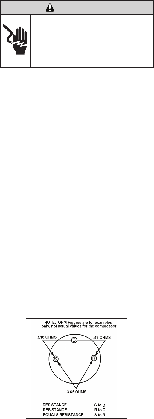
Single Phase Resistance Test
Remove the leads from the compressor terminals and set
the ohmmeter on the lowest scale (R x 1).
Touch the leads of the ohmmeter from terminals common
to start (“C” to “S”). Next, touch the leads of the ohmmeter
from terminals common to run (“C” to “R”).
Add values “C” to “S” and “C” to “R” together and
check resistance from start to run terminals (“S” to “R”).
Resistance “S” to “R” should equal the total of “C” to “S”
and “C” to “R.”
In a single phase PSC compressor motor, the highest
value will be from the start to the run connections (“S” to
“R”). The next highest resistance is from the start to the
common connections (“S” to “C”). The lowest resistance
is from the run to common. (“C” to “R”) Before replacing a
compressor, check to be sure it is defective.
GROUND TEST
Use an ohmmeter set on its highest scale. Touch one
lead to the compressor body (clean point of contact as
a good connection is a must) and the other probe in turn
to each compressor terminal. If a reading is obtained the
compressor is grounded and must be replaced.
Check the complete electrical system to the compressor
and compressor internal electrical system, check to be
certain that compressor is not out on internal overload.
Complete evaluation of the system must be made
whenever you suspect the compressor is defective. If
the compressor has been operating for sometime, a
careful examination must be made to determine why the
compressor failed.
Many compressor failures are caused by the following
conditions:
1. Improper air ow over the evaporator.
2. Overcharged refrigerant system causing liquid to be
returned to the compressor.
3. Restricted refrigerant system.
4. Lack of lubrication.
5. Liquid refrigerant returning to compressor causing oil
to be washed out of bearings.
6. Noncondensables such as air and moisture in
the system. Moisture is extremely destructive to a
refrigerant system.
7. Capacitor test (see page 21).
CHECKING COMPRESSOR EFFICIENCY
The reason for compressor inefciency is normally due
to broken or damaged suction and/or discharge valves,
reducing the ability of the compressor to pump refrigerant
gas.
This condition can be checked as follows:
1. Install a piercing valve on the suction and discharge or
liquid process tube.
2. Attach gauges to the high and low sides of the system.
3. Start the system and run a “cooling or heating perfor-
mance test.” If test shows:
A. Below normal high side pressure
B. Above normal low side pressure
C. Low temperature difference across coil
The compressor valves are faulty - replace the
compressor.
36
ELECTRIC SHOCK HAZARD
WARNING
Turn off electric power before service or
installation. Extreme care must be used, if it
becomes necessary to work on equipment
with power applied.
Failure to do so could result in serious injury or
death.
37
Recommended procedure for compressor
replacement
1. Be certain to perform all necessary electrical and
refrigeration tests to be sure the compressor is
actually defective before replacing.
2. Recover all refrigerant from the system though
the process tubes. PROPER HANDLING OF
RECOVERED REFRIGERANT ACCORDING TO
EPA REGULATIONS IS REQUIRED. Do not use
gauge manifold for this purpose if there has been
a burnout. You will contaminate your manifold and
hoses. Use a Schrader valve adapter and copper
tubing for burnout failures.
3. After all refrigerant has been recovered, disconnect
suction and discharge lines from the compressor and
remove compressor. Be certain to have both suction
and discharge process tubes open to atmosphere.
4. Carefully pour a small amount of oil from the suction
stub of the defective compressor into a clean
container.
9. Evacuate the system with a good vacuum pump capable
of a nal vacuum of 300 microns or less. The system
should be evacuated through both liquid line and suction
line gauge ports. While the unit is being evacuated, seal
all openings on the defective compressor. Compressor
manufacturers will void warranties on units received not
properly sealed. Do not distort the manufacturers tube
connections.
10. Recharge the system with the correct amount of
refrigerant. The proper refrigerant charge will be
found on the unit rating plate. The use of an accurate
measuring device, such as a charging cylinder,
electronic scales or similar device is necessary.
COMPRESSOR REPLACEMENT
5. Using an acid test kit (one shot or conventional kit), test
the oil for acid content according to the instructions
with the kit.
6. If any evidence of a burnout is found, no matter how
slight, the system will need to be cleaned up following
proper procedures.
7. Install the replacement compressor.
8. Pressurize with a combination of R-22 and nitrogen
and leak test all connections with an electronic or
Halide leak detector. Recover refrigerant and repair
any leaks found.
Repeat Step 8 to insure no more leaks are present.
Unplug and/or disconnect all electrical power
to the unit before performing inspections,
maintenances or service.
Failure to do so could result in electric shock,
serious injury or death.
WARNING
RISK OF ELECTRIC SHOCK
Sealed Refrigeration System contains refrigerant
and oil under high pressure.
Proper safety procedures must be followed,
and proper protective clothing must be worn
when working with refrigerants.
Failure to follow these procedures could
result in serious injury or death.
WARNING
HIGH PRESSURE HAZARD
Extreme care, proper judgment and all safety
procedures must be followed when testing,
troubleshooting, handling or working around
unit while in operation with high temperature
components. Wear protective safety aids
such as: gloves, clothing etc.
Failure to do so could result in serious burn
injury.
WARNING
HIGH TEMPERATURES
The use of a torch requires extreme care and proper
judgment. Follow all safety recommended precautions
and protect surrounding areas with re proof materials.
Have a re extinguisher readily available. Failure to follow
this notice could result in moderate to serious property
damage.
NOTICE
FIRE HAZARD
The use of nitrogen requires a pressure
regulator. Follow all safety procedures and
wear protective safety clothing etc.
Failure to follow proper safety procedures
result in serious injury or death.
WARNING
EXPLOSION HAZARD
Proper safety procedures must be followed,
and proper protective clothing must be worn
when working with liquid refrigerant.
Failure to follow these procedures could
result in minor to moderate injury.
CAUTION
FREEZE HAZARD
1.
2.
3.
4.
5.
ELECTRIC SHOCK HAZARD
WARNING
Turn off electric power before service or
installation.
Failure to do so may result in personal injury,
or death.
Sealed Refrigeration System contains refrigerant
and oil under high pressure.
Proper safety procedures must be followed,
and proper protective clothing must be worn
when working with refrigerants.
Failure to follow these procedures could
result in serious injury or death.
WARNING
HIGH PRESSURE HAZARD
The use of nitrogen requires a pressure
regulator. Follow all safety procedures and
wear protective safety clothing etc.
Failure to follow proper safety procedures
result in serious injury or death.
WARNING
EXPLOSION HAZARD
Recover all refrigerant and oil from the system.
Remove compressor, capillary tube and lter drier
from the system.
Flush evaporator condenser and all connecting
tubing with dry nitrogen or equivalent. Use approved
ushing agent to remove all contamination from
system. Inspect suction and discharge line for
carbon deposits. Remove and clean if necessary.
Ensure all acid is neutralized.
Reassemble the system, including new drier strainer
and capillary tube.
Proceed with step 8-10 on previous page.
SPECIAL PROCEDURE IN THE CASE OF MOTOR
COMPRESSOR BURNOUT
Basically, troubleshooting and servicing rotary compres-
sors is the same as on the reciprocating compressor with
only one main exception:
NEVER, under any circumstances, charge a rotary com-
pressor through the LOW side. Doing so would cause
permanent damage to the new compressor.
ROTARY COMPRESSOR SPECIAL TROUBLESHOOTING
AND SERVICE
38
ROUTINE MAINTENANCE
AIR FILTER
Clean the unit air intake lter at least every 300 to 350 hours of operation. Clean the lters with a mild detergent in
warm water and allow to dry thoroughly before reinstalling.
Units are to be inspected and serviced by qualied service
personnel only. Use proper protection on surrounding
property. Failure to follow this notice could result in
moderate or serious property damage.
Do not use a caustic coil cleaning agent on coils or base
pan. Use a biodegradable cleaning agent and degreaser,
to prevent damage to the coil and/or base pan.
NOTICE
NOTICE
BLOWER WHEEL / HOUSING / CONDENSER FAN / SHROUD
Inspect the indoor blower housing, evaporator blade, condenser fan blade and condenser shroud periodically (yearly or
bi-yearly) and clean of all debris (lint, dirt, mold, fungus, etc.). Clean the blower housing area and blower wheel with an
antibacterial / antifungal cleaner. Use a biodegradable cleaning agent and degreaser on condenser fan and condenser
shroud. Use warm or cold water when rinsing these items. Allow all items to dry thoroughly before reinstalling them.
The indoor coil (evaporator coil), the outdoor coil (condenser coil) and base pan should be inspected periodically
(yearly or bi-yearly) and cleaned of all debris (lint, dirt, leaves, paper, etc.). Clean the coils and base pan with a soft
brush and compressed air or vacuum. If using a pressure washer, be careful not to bend the aluminium n pack. Use
a sweeping up and down motion in the direction of the vertical aluminum n pack when pressure cleaning coils. Cover
all electrical components to protect them from water or spray. Allow the unit to dry thoroughly before reinstalling it in
the sleeve.
EXCESSIVE WEIGHT HAZARD
WARNING
Use two people to lift or carry the unit, and wear
proper protective clothing.
Failure to do so may result in personal injury.
39
ELECTRIC SHOCK HAZARD
WARNING
Turn off electric power before inspections,
maintenances, or service.
Extreme care must be used, if it becomes
necessary to work on equipment with power
applied.
Failure to do so could result in serious injury
or death.
ELECTRONIC / ELECTRICAL / MECHANICAL
COILS AND BASE PAN
Periodically (at least yearly or bi-yearly): inspect all control components: electronic, electrical and mechanical, as well
as the power supply. Use proper testing instruments (voltmeter, ohmmeter, ammeter, wattmeter, etc.) to perform elec-
trical tests. Use an air conditioning or refrigeration thermometer to check room, outdoor and coil operating tempera-
tures. Use a sling psychrometer to measure wet bulb temperatures indoors and outdoors.
Inspect the surrounding area (inside and outside) to ensure that the unit’s clearances have not been compromised or
altered.
CUT/SEVER HAZARD
WARNING
Be careful with the sharp edges and corners.
Wear protective clothing and gloves, etc.
Failure to do so could result in serious injury.
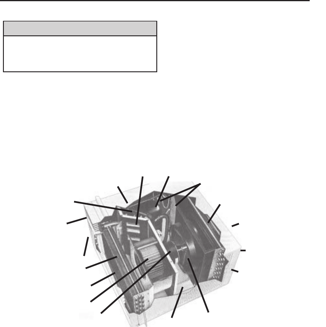
SLEEVE / DRAIN
Inspect the sleeve and drain system periodically (at least yearly or bi-yearly) and clean of all obstructions and
debris. Clean both areas with an antibacterial and antifungal cleaner. Rinse both items thoroughly with water and
ensure that the drain outlets are operating correctly. Check the sealant around the sleeve and reseal areas as
needed.
FRONT COVER
Clean the front cover when needed. Use a mild detergent. Wash and rinse with warm water. Allow it to dry
thoroughly before reinstalling it in the chassis.
ROUTINE MAINTENANCE (Continued)
Do not drill holes in the bottom of the drain pan or the
underside of the unit. Not following this notice could
result in damage to the unit or condensate water leaking
inappropriately which could cause water damage to
surrounding property.
NOTICE
Return Air Grille/Filter
Discharge Air
Evaporator Coil
Blower Wheel
Capillary Tube
Condenser Fan Blade
Outdoor Grille
Sleeve
Condenser Coil
Compressor
Basepan
Front Cover
System Switches
Reversing Valve
(some models)
Fresh Air
Liquid Filter Driers
Blower Motor
40
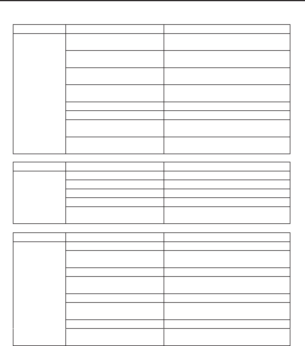
COOLING ONLY ROOM AIR CONDITIONERS: TROUBLESHOOTING TIPS
41
noitcA esuaC elbissoP melborP
Compressor
does not run
Low voltage Check voltage at compressor. 115V & 230V
units will operate at 10% voltage variance
T-stat not set cold enough or
inoperative
Set t-stat to coldest position. Test t-stat & re-
place if inoperative
Compressor hums but cuts off on
overload
Hard start compressor. Direct test compressor.
If compressor starts, add starting components
Open or shorted compressor
windings Check for continuity & resistance
Open overload Test overload protector & replace if inoperative
Open capacitor Test capacitor & replace if inoperative
Inoperative system switch Test for continuity in all positions. Replace if
inoperative
Broken, loose or incorrect wiring Refer to appropriate wiring diagrams to check
wiring
noitcA esuaC elbissoP melborP
Fan motor
does not run
Inoperative system switch Test switch & replace if inoperative
Broken, loose or incorrect wiring Refer to applicable wiring diagram
Open capacitor Test capacitor & replace if inoperative
Fan speed switch open Test switch & replace if inoperative
Inoperative fan motor Test fan motor & replace if inoperative (be sure
internal overload has had time to reset)
noitcA esuaC elbissoP melborP
Does not cool or
only cools slightly
Undersized unit Refer to industry standard sizing chart
T-stat open or inoperative Set to coldest position. Test t-stat & replace if
necessary
Dirty fi launaM s’renwO ni dednemmocer sa naelC retl
Dirty or restricted condenser or
evaporator coil
Use pressure wash or biodegradable cleaning
agent to clean
Poor air circulation Adjust discharge louvers. Use high fan speed
Fresh air or exhaust air door open
on applicable models
Close doors. Instruct customer on use of this
feature
Low capacity - undercharge Check for leak & make repair
Compressor not pumping properly Check amperage draw against nameplate. If
not conclusive, make pressure test

COOLING ONLY ROOM AIR CONDITIONERS: TROUBLESHOOTING TIPS
42
noitcA esuaC elbissoP melborP
Unit does not run
Fuse blown or circuit tripped
Replace fuse, reset breaker. If repeats, check
fuse or breaker size. Check for shorts in unit
wiring & components
Power cord not plugged in Plug it in
System switch in “OFF” position Set switch correctly
Inoperative system switch or open
control board Test for continuity
Loose or disconnected wiring at
switch, control board or other com-
ponents
Check wiring & connections. Reconnect per
wiring diagram
noitcA esuaC elbissoP melborP
Evaporator coil
freezes up
Dirty fi launaM s’renwO ni dednemmocer sa naelC retl
Restricted airfl ow
Check for dirty or obstructed coil. Use
pressure wash or biodegradable cleaning
agent to clean
Inoperative t-stat or thermistors Test for continuity
Short of refrigerant De-ice coil & check for leak
Inoperative fan motor Test fan motor & replace if inoperative
Partially restricted capillary tube
De-ice coil. Check temp. differential (delta T)
across coil. Touch test coil return bends for
same temp. Test for low running current
noitcA esuaC elbissoP melborP
Compressor runs
continually & does
not cycle off
Excessive heat load Unit undersized. Test cooling performance &
replace with larger unit if needed
Restriction in line Check for partially iced coil & check
temperature split across coil
Refrigerant leak
Check for oil at silver soldered connections.
Check for partially iced coil. Check split across
coil. Check for low running amperage
T-stat contacts stuck Check operation of t-stat. Replace if contacts
remain closed.
T-stat incorrectly wired Refer to appropriate wiring diagram
Thermistor shorted Replace thermistor or electronic control board
noitcA esuaC elbissoP melborP
T-stat does not
turn unit off
T-stat contacts stuck
Disconnect power to unit. Remove cover
of t-stat & check if contacts are stuck. If so,
replace t-stat
T-stat set at coldest point Turn to higher temp. setting to see if unit
cycles off
Incorrect wiring Refer to appropriate wiring diagrams
Unit undersized for area to be
cooled Refer to industry standard sizing chart
Defective thermistor Replace thermistor or electronic control board
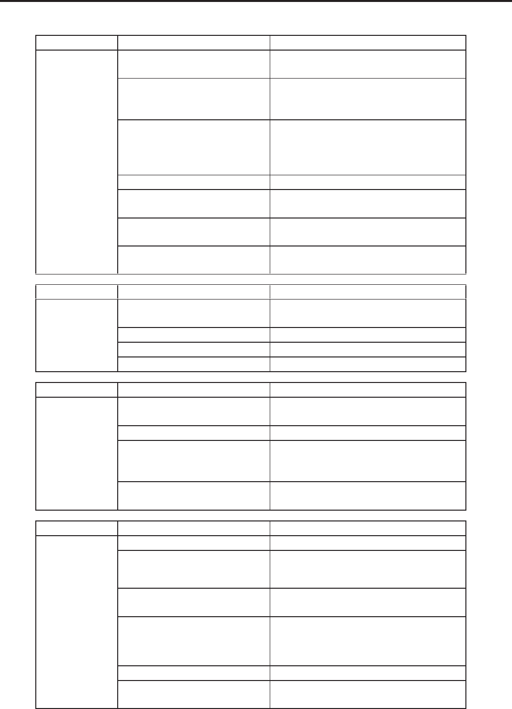
COOLING ONLY ROOM AIR CONDITIONERS: TROUBLESHOOTING TIPS
43
noitcA esuaC elbissoP melborP
Compressor runs
for short periods
only. Cycles on
overload
Overload inoperative. Opens too
soon
Check operation of unit. Replace overload if
system operation is satisfactory
Compressor restarted before
system pressures equalized
Allow a minimum of 2 minutes to allow
pressures to equalize before attempting to
restart. Instruct customer of waiting period
Low or fl uctuating voltage
Check voltage with unit operating. Check for
other appliances on circuit. Air conditioner
should be in separate circuit for proper voltage
& fused separately
Incorrect wiring Refer to appropriate wiring diagram
Shorted or incorrect capacitor Check by substituting a known good capacitor
of correct rating
Restricted or low air fl ow through
condenser coil or evaporator coil
Check for proper fan speed or blocked
coils
Compressor running abnormally
hot
Check for kinked discharge line or restricted
condenser. Check amperage
noitcA esuaC elbissoP melborP
T-stat does not
turn unit on
Loss of charge in t-stat bulb Place jumper across t-stat terminals to check if
unit operates. If unit operates, replace t-stat.
Loose or broken parts in t-stat Check as above
Incorrect wiring Refer to appropriate wiring diagram
Defective thermistor Replace thermistor or electronic control board
noitcA esuaC elbissoP melborP
Noisy operation
Poorly installed Refer to Installation Manual for proper
installation
Fan blade striking chassis Reposition - adjust motor mount
Compressor vibrating
Check that compressor grommets have not
deteriorated. Check that compressor mounting
parts are not missing
Improperly mounted or loose
cabinet parts
Check assembly & parts for looseness,
rubbing & rattling
noitcA esuaC elbissoP melborP
Water leaks into
the room
Evaporator drain pan overfl owing Clean obstructed drain trough
Condensation forming on base pan
Evaporator drain pan broken or cracked.
Reseal or replace. No chassis gasket installed.
Install chassis gasket
Poor installation resulting in rain
entering the room
Check installation instructions. Reseal as
required
Condensation on discharge grille
louvers
Dirty evaporator coil. Use pressure wash
or biodegradable cleaning agent to clean.
Environmental phenomena: point supply
louvers upward
Chassis gasket not installed Install gasket, per Installation manual
Downward slope of unit is too
steep inward
Refer to installation manual for proper
installation
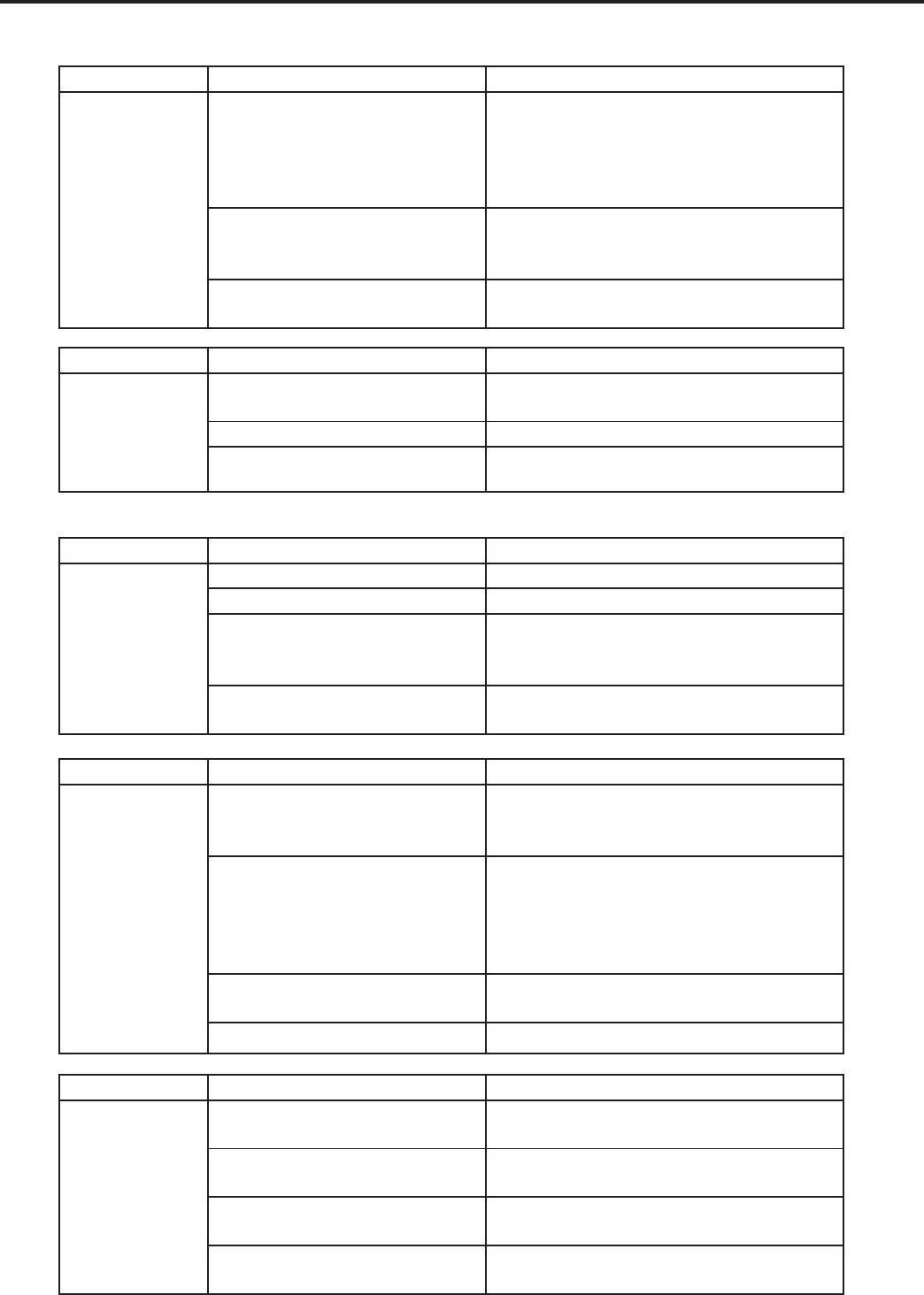
COOLING ONLY ROOM AIR CONDITIONERS: TROUBLESHOOTING TIPS
44
noitcA esuaC elbissoP melborP
Water “spitting”
into room
Sublimation:
When unconditioned saturated,
outside air mixes with conditioned
air, condensation forms on the
cooler surfaces
Ensure that foam gaskets are installed in
between window panes & in between the
unit & the sleeve. Also, ensure that fresh
air/exhaust vents (on applicable models) are in
the closed position & are in tact
Downward pitch of installation is
too steep towards back of unit
Follow installation instructions to ensure that
downward pitch of installed unit is no less than
1/4” & no more than 3/8”
Restricted coil or dirty fi lter Clean & advise customer of periodic cleaning
& maintenance needs of entire unit
noitcA esuaC elbissoP melborP
Excessive
moisture
Insuffi cient air circulation thru area
to be air conditioned Adjust louvers for best possible air circulation
noitisop ”revaSyenoM“ ni etarepO tinu dezisrevO
Inadequate vapor barrier in building
structure, particularly fl oors Advise customer
noitcA esuaC elbissoP melborP
T-stat or
thermistor
short cycles
Defective thermistor Replace thermistor or electronic control board
T-stat differential too narrow Replace t-stat
Plenum gasket not sealing,
allowing discharge air to short
cycle t-stat
Check gasket. Reposition or replace as
needed
Restricted coil or dirty fi lter Clean & advise customer of periodic cleaning
& maintenance needs of entire unit
noitcA esuaC elbissoP melborP
Prolonged off
cycles (automatic
operation)
Heat anticipator (resistor) wire
disconnected at t-stat or system
switch
Refer to appropriate wiring diagram
Heat anticipator (resistor) shorted or
open
Disconnect plus from outlet. Remove resistor
from bracket. Insert plug & depress “COOL”
& “FAN AUTOMATIC” buttons. Place t-stat to
warmest setting. Feel resistor for temperature.
If no heat, replace resistor
Partial loss of charge in t-stat bulb
causing a wide differential Replace t-stat
Defective thermistor Replace thermistor or electronic control board
noitcA esuaC elbissoP melborP
Outside water
leaks
Evaporator drain pan cracked or
obstructed Repair, clean or replace as required
Water in compressor area Detach shroud from pan & coil. Clean &
remove old sealer. Reseal, reinstall & check
Obstructed condenser coil Use pressure wash or biodegradable cleaning
agent to clean
Fan blade/slinger ring improperly
positioned
Adjust fan blade to 1/2” of condenser coil fi n
pack
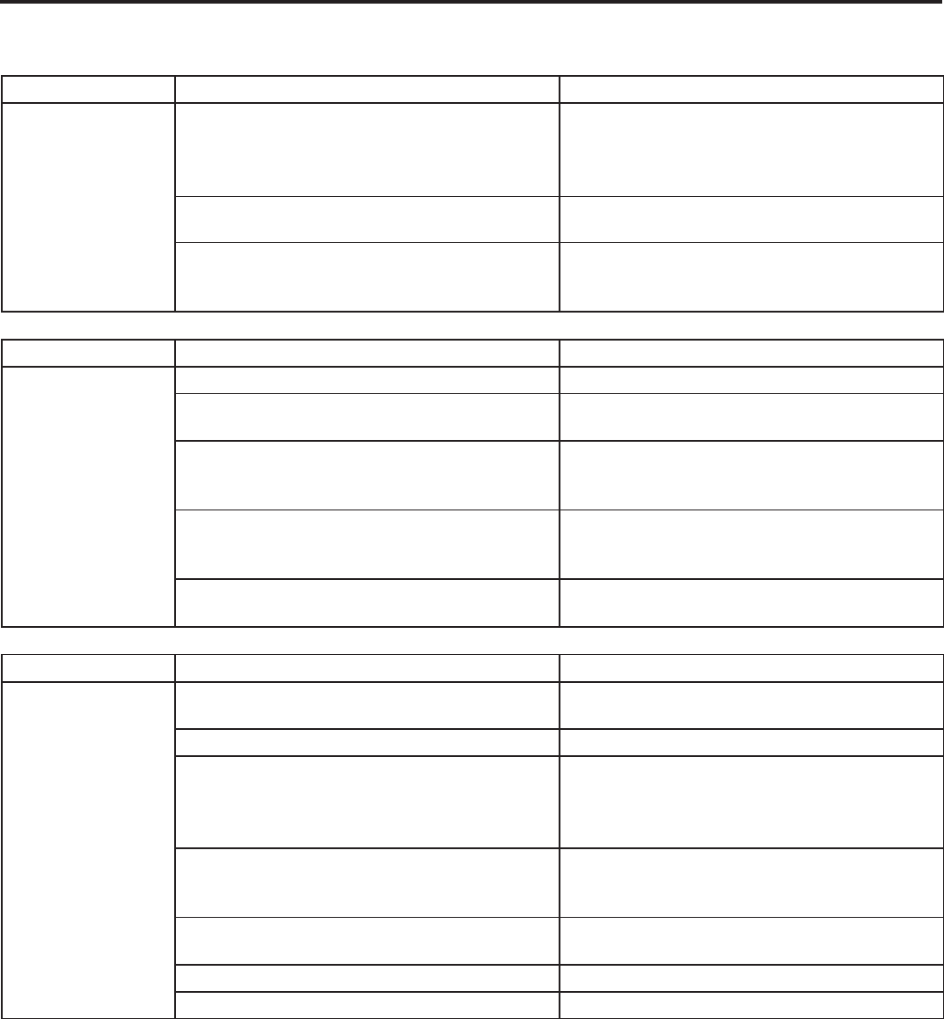
HEAT / COOL ONLY ROOM AIR CONDITIONERS: TROUBLESHOOTING TIPS
45
noitcAesuaC elbissoPmelborP
Room temperature
uneven
(Heating cycle)
Heat anticipator (resistor) shorted (on applicable
models)
Disconnect power to unit. Remove resistor from
t-stat bulb block. Plus in unit & allow to operate.
Feel resistor for heat. If not heat, replace resistor
Wide differential - partial loss of t-stat bulb chargeReplace t-stat & check
Incorrect wiring
Refer to appropriate wiring diagram. Resistor is
energized during "ON" cycle of compressor or
fan.
noitcAesuaC elbissoPmelborP
Unit will not defrost
margaid gniriw etairporppa ot refeRgniriw tcerrocnI
Defrost control timer motor not advancing
(applicable models)
Check for voltage at "TM" & "TM1" on timer. If no
voltage, replace control
Defrost control out of calibration (applicable
models)
If outside coil temperature is 25F or below, &
preselected time limit has elapsed, replace
defrost control
Defrost control contacts stuck
If contacts remain closed between terminals "2"
& "3" of the defrost control after preselected time
interval has passed, replace control
Defrost control bulb removed from or not making
good coil contact
Reinstall & be assured that good bulb to coil
contact is made
noitcAesuaC elbissoPmelborP
Does not heat
adequately
Exhaust or fresh air door openCheck if operating properly. Instruct customer on
proper use of control
Dirty filaunaM s'renwO ni dednemmocer sa naelCretl
Unit undersized
Check heat rise across coil. If unit operates
effi ciently, check if insulation can be added
to attic or walls. If insulation is adequate,
recommend additional unit or larger one
Outdoor t-stat open (applicable models)
T-stat should close at 38°F. Check continuity of
control. If temperature is below 38°F, replace
control
Heater hi-limit control cycling on & off Check for adequate fan air across heater. Check
control for open at 160°F & close at 150°F
Shorted supplementary heater Ohmmeter check, approx. 32-35 ohms
margaid gniriw elbacilppa kcehCgniriw tcerrocnI
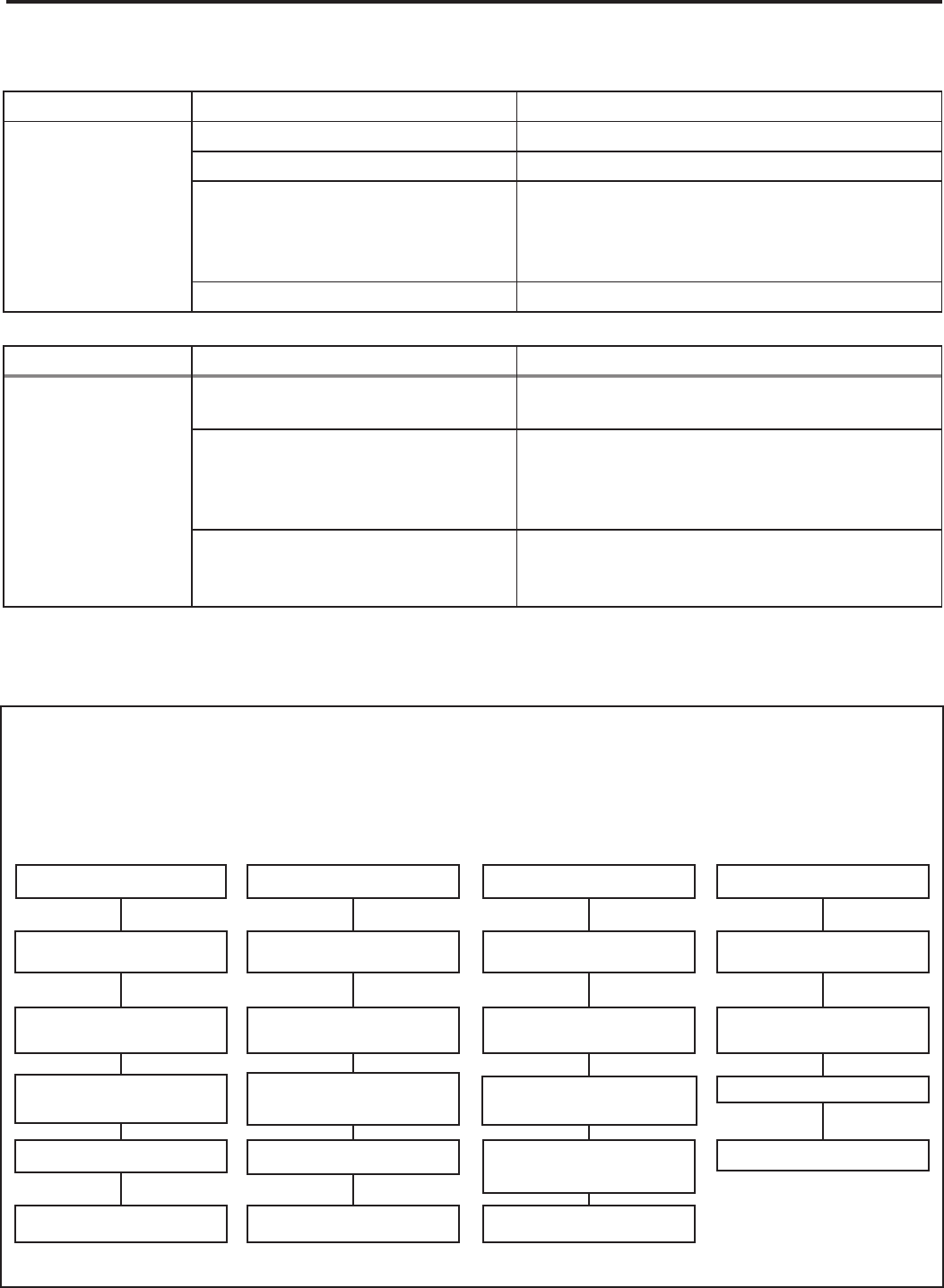
46
noitcAesuaC elbissoPmelborP
Unit cools when
heat is called for
Incorrect wiring Refer to applicable wiring diagram
Defective solenoid coil Check for continuity of coil
Reversing valve fails to shift
Block condenser coil & switch unit to cooling.
Allow pressure to build up in system, then
switch to heating. If valve fails to shift, replace
valve.
Inoperative system switch Check for continuity of system switch
noitcAesuaC elbissoPmelborP
Cooling adequate,
but heating
insuffi cient
Heating capillary tube partially
restricted
Check for partially starved outer coil. Replace
heating capillary tube
Check valve leaking internally
Switch unit several times from heating to
cooling. Check temperature rise across
coil. Refer to specifi cation sheet for correct
temperature rise
Reversing valve failing to shift
completely; bypassing hot gas
Deenergize solenoid coil, raise head pressure,
energize solenoid to break loose. If valve fails
to make complete shift, replace valve.
TROUBLESHOOTING CHART — HEATPUMP
HEAT / COOL ROOM AIR CONDITIONERS: TROUBLE SHOOTING TIPS
LOW SUCTION PRESSURE HIGH SUCTION PRESSURE LOW HEAD PRESSURE HIGH HEAD PRESSURE
Low Load Conditions High Load Conditions Low Load Conditions High Load Conditions
Low Air Flow Across High Air Flow Across Refrigerant System Low Air Flow Across
Indoor Coil Indoor Coil Restriction Outdoor Coil
Refrigerant System Reversing Valve not Reversing Valve not Overcharged
Restriction Fully Seated Fully Seated
Undercharged Overcharged Undercharged Noncondensables (air)
metsyS ni
Moisture in System Defective Compressor Defective Compressor
REFRIGERANT SYSTEM DIAGNOSIS - COOLING CYCLE
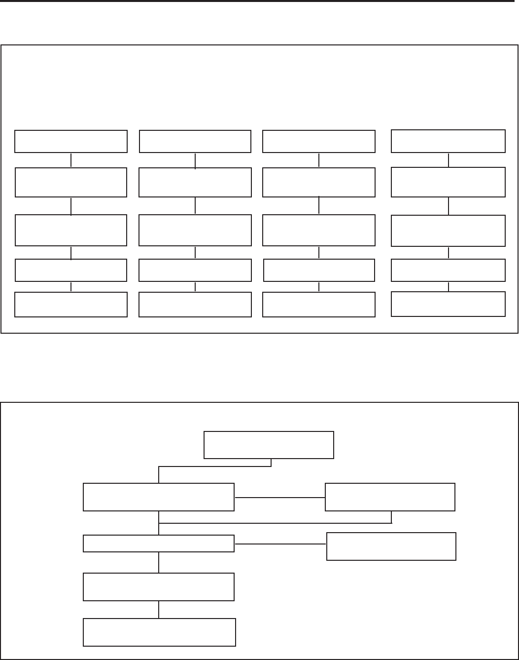
47
ELECTRICAL TROUBLESHOOTING CHART — HEAT PUMP
Reversing Valve Stuck
Replace the Reversing Valve
Replace the Solenoid Coil
NO
Is the Solenoid Coil Good?
Is Line Voltage
Present at the Solenoid
Is the Selector Switch
Set for Heat?
NO
SYSTEM COOLS WHEN
HEATING IS DESIRED.
YES
HEAT PUMP
YES
TROUBLESHOOTING CHART — HEATPUMP
Noncondensables (air)
in System
Overcharged
Low Airfl ow Across
Indoor Coil
Outdoor Ambient Too High
For Operation In Heating
Moisture in System Defective Compressor Defective Compressor
Undercharged Overcharged Undercharged
Refrigerant System
Restriction
Reversing Valve not
Fully Seated
Low Airfl ow
Across Outdoor Coil
Outdoor Ambient Too High
for Operation in Heating
Refrigerant System
Restriction
Reversing Valve not
Fully Seated
REFRIGERANT SYSTEM DIAGNOSIS - HEATING CYCLE
LOW SUCTION PRESSURE HIGH SUCTION PRESSURE LOW HEAD PRESSURE HIGH HEAD PRESSURE
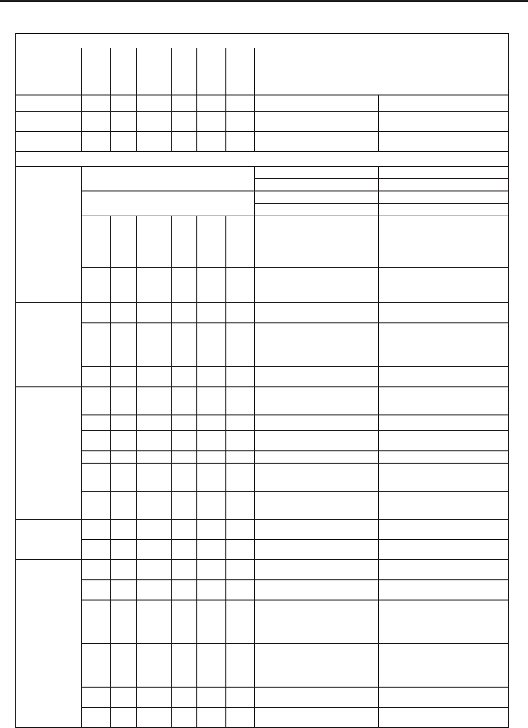
TROUBLESHOOTING TOUCH TEST CHART: TO SERVICE REVERSING VALVES
DISCHARGE TUBE
SUCTION TUBE to
Tube to OUTSIDE
from Compressor
Tube to INSIDE
Capillary Tube
Capillary Tube
Compressor
RIGHT Pilot
LEFT Pilot
COIL
COIL
14
NORMAL FUNCTION OF VALVE
VALVE
OPERATING
DISCHARGE TUBE
from Compressor
SUCTION TUBE
to Compressor
Tube to INSIDE
COIL
Tube to OUTSIDE
COIL
LEFT Pilot
Capillary Tube
RIGHT Pilot
Capillary Tube
CONDITION
NOTES:
* TEMPERATURE OF VALVE BODY
** WARMER THAN VALVE BODY
1 2 3 4 5 6 POSSIBLE CAUSES CORRECTIONS
Normal Cooling Hot Cool Cool
as (2)
Hot
as (1) *TVB TVB
Normal Heating Hot Cool Hot
as (1)
Cool
as (2) *TVB TVB
MALFUNCTION OF VALVE
Valve will not
shift from cool
to heat.
Check Electrical circuit and coil
.tiucric lacirtcele riapeR .lioc ot egatlov oN
.lioc ecalpeR .lioc evitcefeD
Check refrigeration charge
.metsys egrahcer ,kael riapeR .egrahc woL
Pressure differential too high. Recheck system.
Hot Cool Cool,
as (2)
Hot,
as (1) *TVB Hot Pilot valve okay. Dirt in one bleeder hole.
Deenergize solenoid, raise head pressure,
reenergize solenoid to break dirt loose.
If unsuccessful, remove valve, wash
out. Check on air before installing. If no
movement, replace valve, add strainer to
discharge tube, mount valve horizontally.
Piston cup leak
Stop unit. After pressures equalize, restart
with solenoid energized. If valve shifts,
reattempt with compressor running. If still
no shift, replace valve.
Valve will not
shift from cool
to heat.
Hot Cool Cool,
as (2)
Hot,
as (1) *TVB *TVB Clogged pilot tubes. Raise head pressure, operate solenoid to
free. If still no shift, replace valve.
Hot Cool Cool,
as (2)
Hot,
as (1) Hot Hot Both ports of pilot open. (Back seat port
did not close).
Raise head pressure, operate solenoid
to free
partially clogged port. If still no shift,
replace
valve.
Warm Cool Cool,
as (2)
Hot,
as (1) *TVB Warm Defective Compressor. Replace compressor
Starts to shift
but does not
complete
reversal.
Hot Warm Warm Hot *TVB Hot
Not enough pressure differential at start
of stroke or not enough fl ow to maintain
pressure differential.
Check unit for correct operating pressures
and charge. Raise head pressure. If no
shift, use valve with smaller port.
evlav ecalpeR .egamad ydoB
Hot Warm Warm Hot Hot Hot Both ports of pilot open. Raise head pressure, operate solenoid. If
no shift, use valve with smaller ports.
evlav ecalpeR .egamad ydoB toH BVT* toH toH toH toH
Valve hung up at mid-stroke. Pumping
volume of compressor not suffi cient to
maintain reversal.
Raise head pressure, operate solenoid. If
no shift, use valve with smaller ports.
Hot Hot Hot Hot Hot Hot Both ports of pilot open.
Raise head pressure, operate solenoid.
If no
shift, replace valve.
Apparent
leap in heat-
ing.
Hot Cool Hot,
as (1)
Cool,
as (2) *TVB *TVB Piston needle on end of slide leaking. Operate valve several times, then recheck.
If excessive leak, replace valve.
Hot Cool Hot,
as (1)
Cool,
as (2) **WVB **WVB Pilot needle and piston needle leaking. Operate valve several times, then recheck.
If excessive leak, replace valve.
Will not shift
from heat to
cool.
Hot Cool Hot,
as (1)
Cool,
as (2) *TVB *TVB Pressure differential too high. Stop unit. Will reverse during equalization
period. Recheck system
Clogged pilot tube. Raise head pressure, operate solenoid to
free dirt. If still no shift, replace valve.
Hot Cool Hot,
as (1)
Cool,
as (2) Hot *TVB Dirt in bleeder hole.
Raise head pressure, operate solenoid.
Remove valve and wash out. Check on air
before reinstalling, if no movement, replace
valve. Add strainer to discharge tube.
Mount valve horizontally.
Hot Cool Hot,
as (1)
Cool,
as (2) Hot *TVB Piston cup leak.
Stop unit. After pressures equalize, restart
with solenoid deenergized. If valve shifts,
reattempt with compressor running. If it
still will not reverse while running, replace
the valve.
Hot Cool Hot,
as (1)
Cool,
as (2) .evlav ecalpeR .tolip evitcefeD toH toH
Warm Cool Warm,
as (1)
Cool,
as (2) Warm *TVB Defective compressor. Replace compressor
48
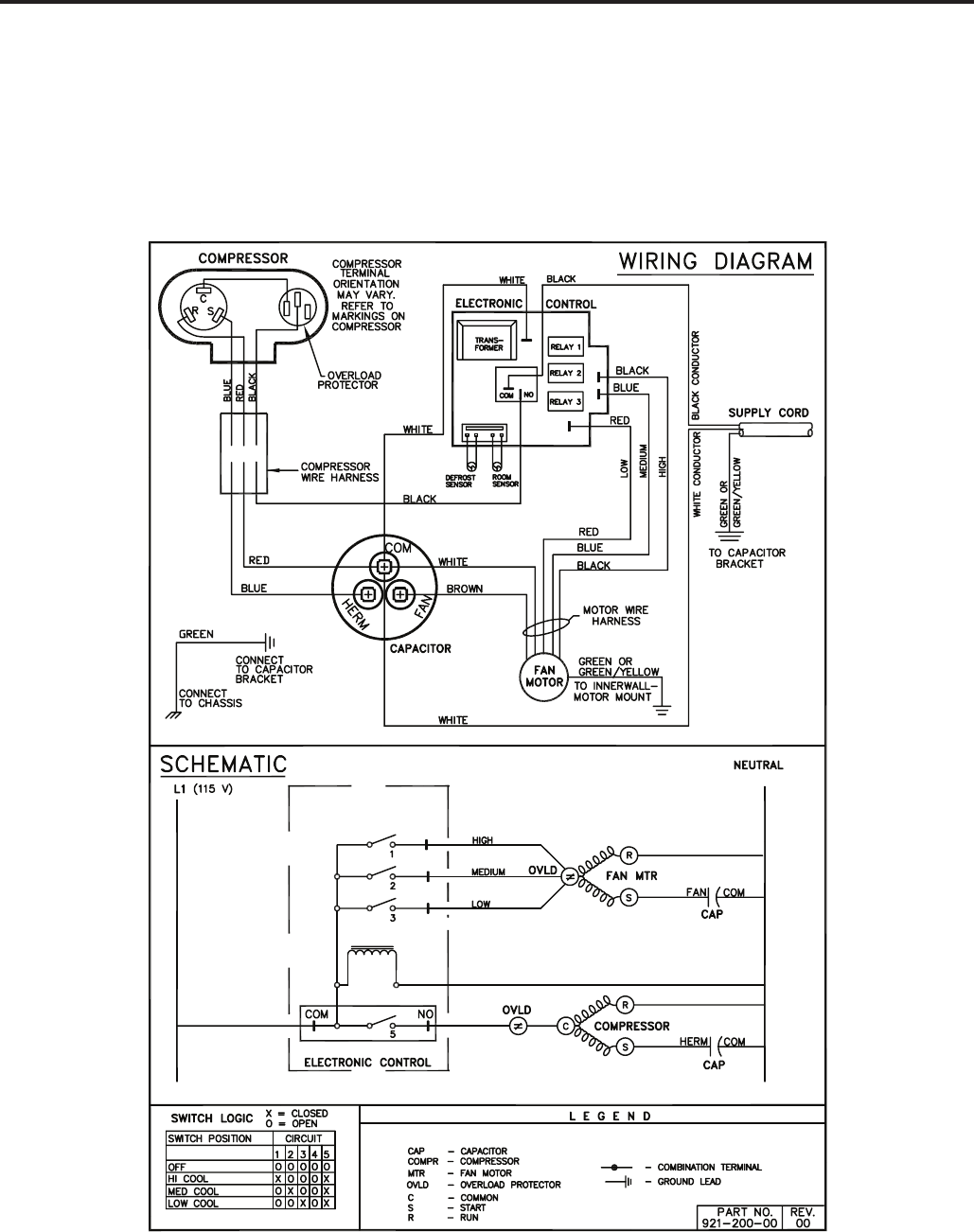
ELECTRONIC CONTROL
COOL ONLY MODELS:
XQ05L10A-C XQ06L10A-C XQ08L10A-B,A-E
XQ10L10A-C XQ12L10A-B,A-C
49
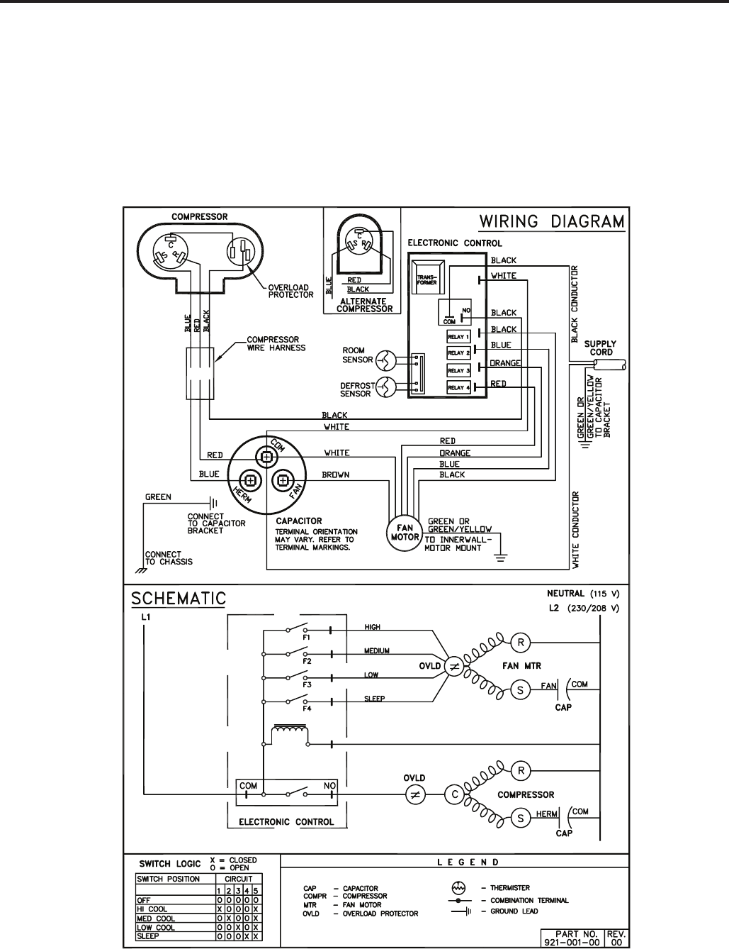
ELECTRONIC CONTROL
COOL ONLY MODELS:
SS08L10-E,-F,-G SS10L10-D,-E SS12L10-E,-F
SS14L10-D,-E SS12L30-E,-F SS16L30-D,-E
SM18L30A-D,A-E SM21L30-E,-F SM24L30-C,-D
50
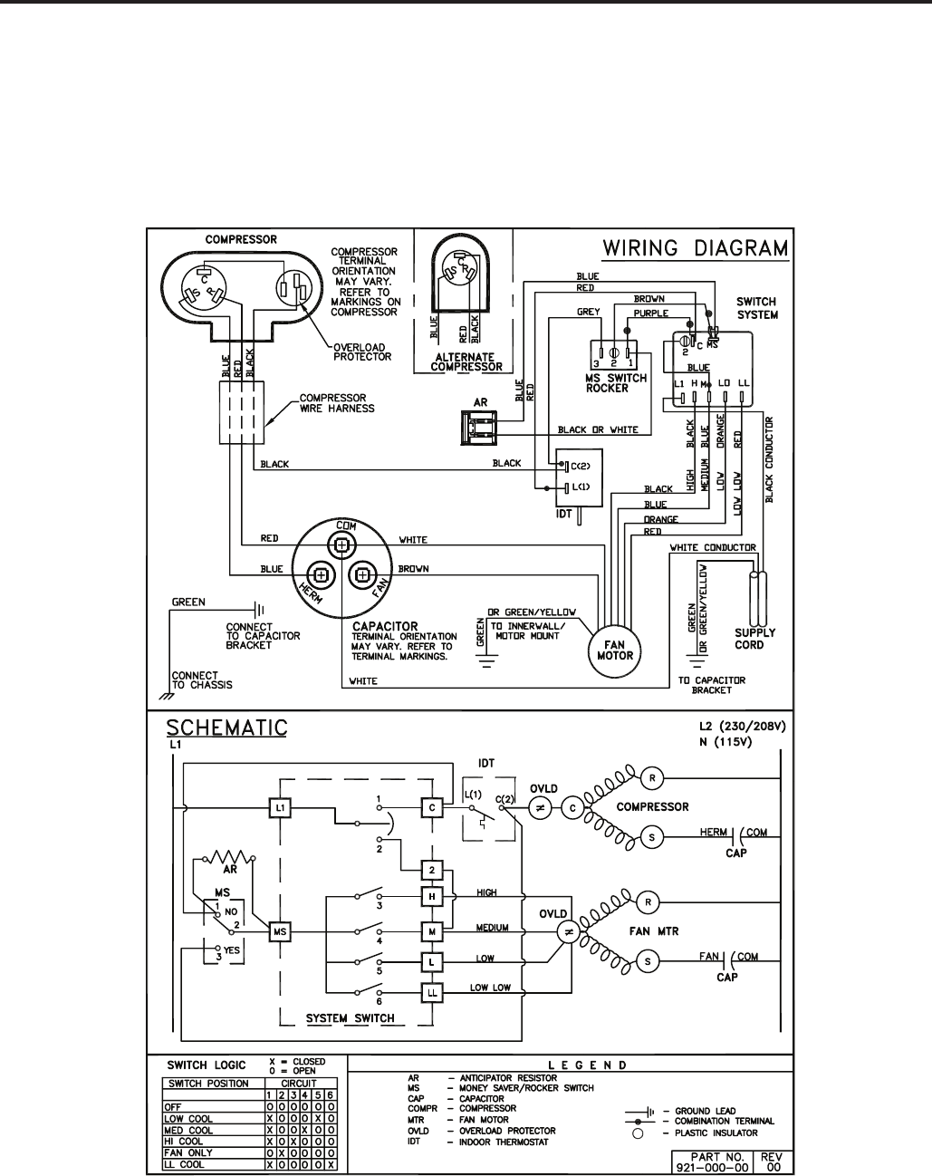
ELECTROMECHANICAL CONTROL
COOL ONLY MODELS:
KS12L10-E,-F KS15L10-C,-D
KM18L30-C,-D KM24L30-C,-D
51
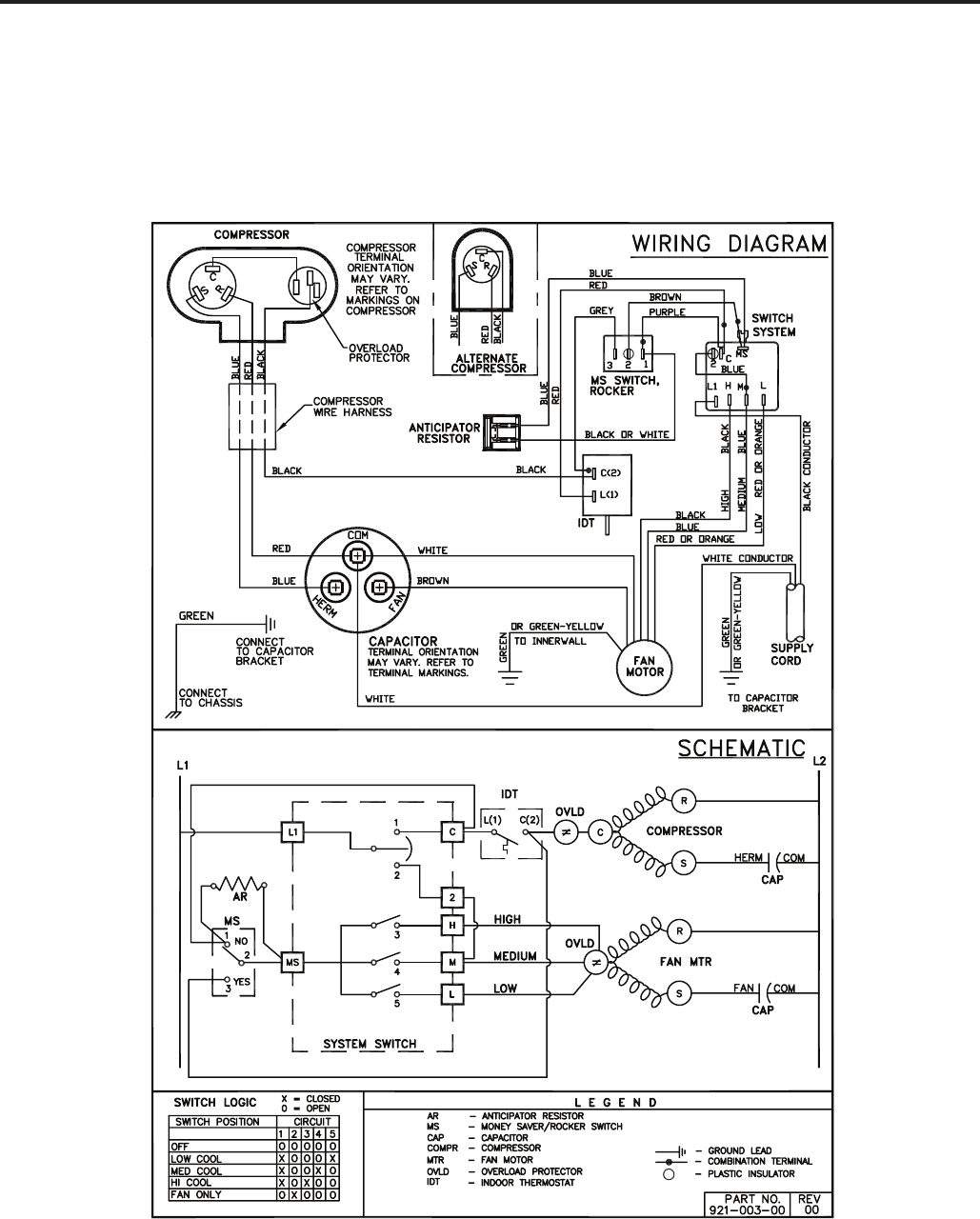
ELECTROMECHANICAL CONTROL
COOL ONLY MODELS:
SL28L30-D,-E SL36L30A-D,A-E
52
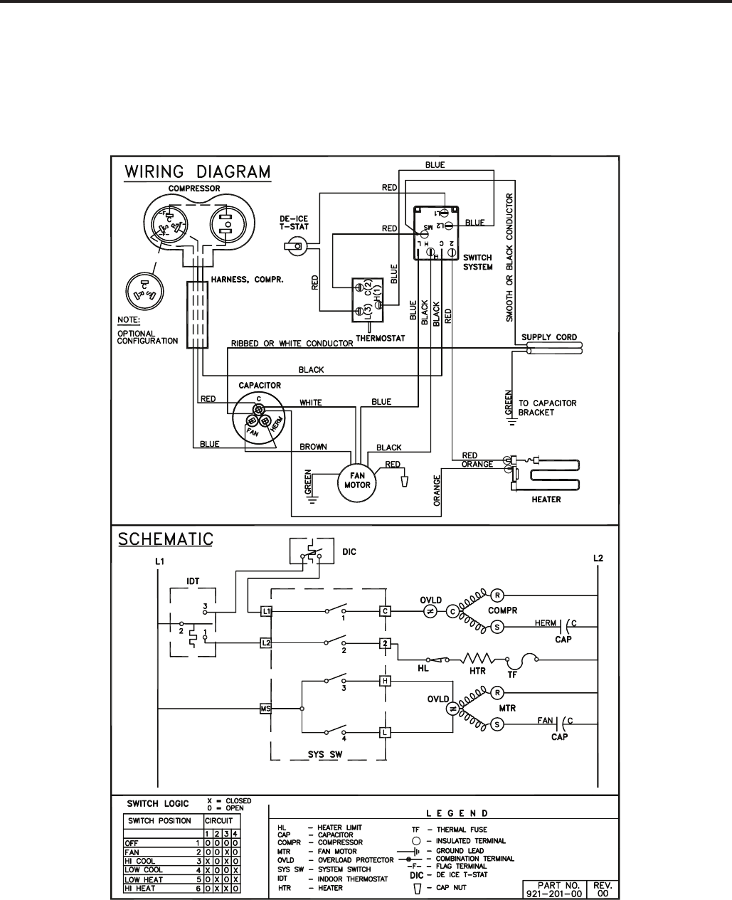
ELECTROMECHANICAL CONTROL
COOL WITH ELECTRIC HEAT MODEL:
EQ08L11A-B,A-E
53
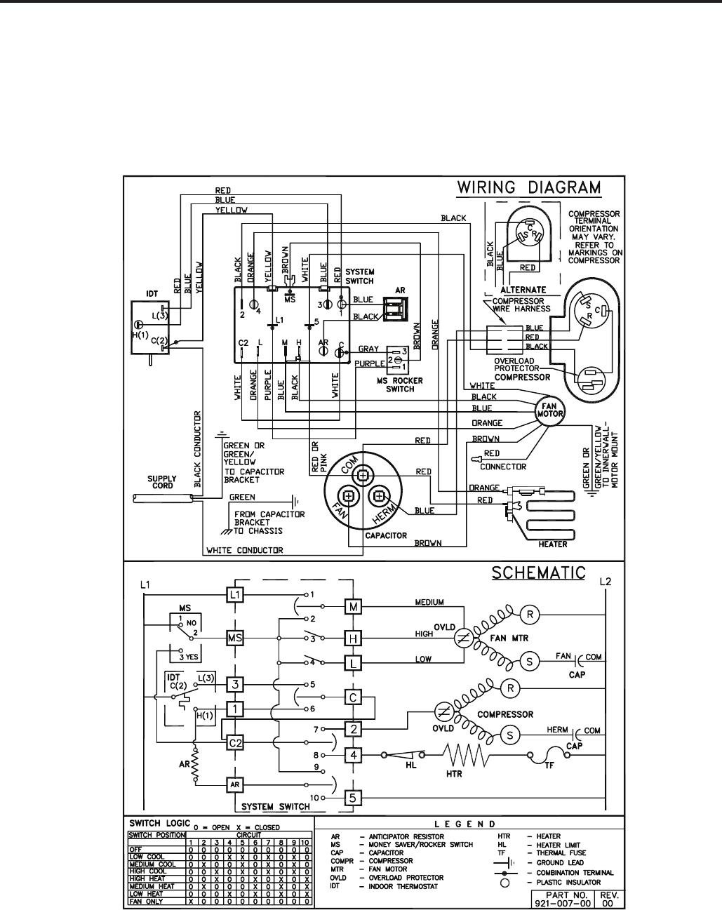
ELECTROMECHANICAL CONTROL
COOL WITH ELECTRIC HEAT MODELS:
ES12L33-D,-E ES16L33-C,-D
EM18L34-C EM24L34-B
54
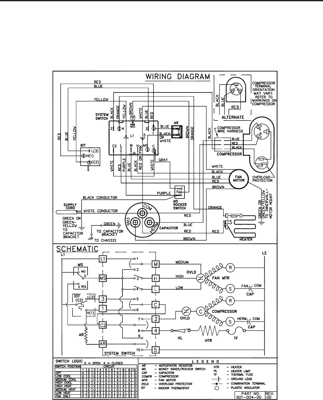
ELECTROMECHANICAL CONTROL
COOL WITH ELECTRIC HEAT MODELS:
EL36L35A-D,A-E
55
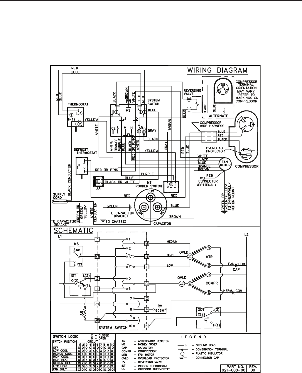
ELECTROMECHANICAL CONTROL
HEAT PUMP ONLY MODELS:
YS09L10-F,-G
56
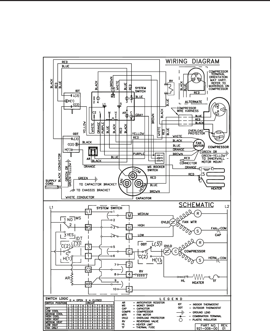
ELECTROMECHANICAL CONTROL
HEAT PUMP WITH ELECTRIC HEAT MODELS:
YS13L33-D,-E YM18L34-D,-E
57
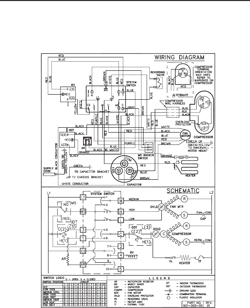
ELECTROMECHANICAL CONTROL
HEAT PUMP WITH ELECTRIC HEAT MODELS:
YL24L35-E,-F
58

4
INSTRUCTIONS FOR USING COOLING LOAD ESTIMATE
FORM FOR ROOM AIR CONDITIONERS
(AHAM PUB. NO. RAC-1)
A. This cooling load estimate form is suitable for estimating the cooling load for comfort air conditioning installations
which do not require specifi c conditions of inside temperature and humidity.
B. The form is based on an outside design temperature of 95°F dry bulb and 75°F wet bulb. It can be used for areas
in the continental United States having other outside design temperatures by applying a correction factor for the
particular locality as determined from the map.
C. The form includes “day” factors for calculating cooling loads in rooms where daytime comfort is desired (such as
living rooms, offi ces, etc.)
D. The numbers of the following paragraphs refer to the corresponding numbered item on the form:
1. Multiply the square feet of window area for each exposure by the applicable factor. The window area is the
area of the wall opening in which the window is installed. For windows shaded by inside shades or venetian
blinds, use the factor for “Inside Shades.” For windows shaded by outside awnings or by both outside aw-
nings and inside shades (or venetian blinds), use the factor for “Outside Awnings.” “Single Glass” includes
all types of single thickness windows, and “Double Glass” includes sealed airspace types, storm windows,
and glass block. Only one number should be entered in the right hand column for Item 1, and this number
should represent only the exposure with the largest load.
2. Multiply the total square feet of all windows in the room by the applicable factor.
3a. Multiply the total length (linear feet) of all walls exposed to the outside by the applicable factor. Doors should
be considered as being part of the wall. Outside walls facing due north should be calculated separately from
outside walls facing other directions. Walls which are permanently shaded by adjacent structures should be
considered “North Exposure.” Do not consider trees and shrubbery as providing permanent shading. An
uninsulated frame wall or a masonry wall 8 inches or less in thickness is considered “Light Construction.” An
insulated wall or masonry wall over 8 inches in thickness is considered “Heavy Construction.”
3b. Multiply the total length (linear feet) of all inside walls between the space to be conditioned and any uncondi-
tioned spaces by the given factor. Do not include inside walls which separate other air conditioned rooms.
4. Multiply the total square feet of roof or ceiling area by the factor given for the type of construction most nearly
describing the particular application (use one line only.)
5. Multiply the total square feet of fl oor area by the factor given. Disregard this item if the fl oor is directly on the
ground or over a basement.
6. Multiply the number of people who normally occupy the space to be air conditioned by the factor given. Use
a minimum of 2 people.
7. Determine the total number of watts for light and electrical equipment, except the air conditioner itself, that
will be in use when the room air conditioning is operating. Multiply the total wattage by the factor given.
8. Multiply the total width (linear feet) of any doors or arches which are continually open to an unconditioned
space by the applicable factor.
NOTE: Where the width of the doors or arches is more than 5 feet, the actual load may exceed the calculated
value. In such cases, both adjoining rooms should be considered as a single large room, and the room air
conditioner unit or units should be selected according to a calculation made on this new basis.
9. Total the loads estimated for the foregoing 8 items.
10. Multiply the subtotal obtained in item 9 by the proper correction factor, selected from the map, for the particular
locality. The result is the total estimated design cooling load in BTU per hour.
E. For best results, a room air conditioner unit or units having a cooling capacity rating (determined in accordance
with the NEMA Standards Publication for Room Air Conditioners, CN 1-1960) as close as possible to the estimated
load should be selected. In general, a greatly oversized unit which would operate intermittently will be much less
satisfactory than one which is slightly undersized and which would operate more nearly continuously.
F. Intermittent loads such as kitchen and laundry equipment are not included in this form.
59
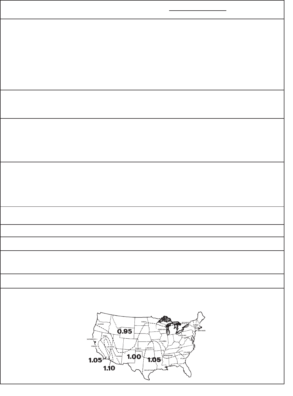
5
COOLING LOAD ESTIMATE FORM
HEAT GAIN FROM
1. WINDOWS: Heat gain from the sun.
Northeast
East
Southeast
South
Southwest
West
Northwest
North
2. WINDOWS: Heat by conduction
(Total of all windows.)
Single glass
Double glass or glass block
3. WALLS: (Based on linear feet of wall)
a. Outside walls
North Exposure
Other than North exposure
b. Inside Walls (between conditioned and
unconditioned spaces only.)
4. ROOF OR CEILING: (Use one only)
a. Roof, uninsulated
b. Roof, 1 inch or more insulation
c. Ceiling, occupied space above
d. Ceiling, insulated, with attic space above
e. Ceiling, uninsulated, with attic space above
5. Floor: (Disregard if fl oor is directly on ground or
over a basement.
6. NUMBER OF PEOPLE
7. LIGHTS AND ELECTRICAL EQUIPMENT IN USE
8. DOORS AND ARCHES CONTINUOUSLY
OPENED TO UNCONDITIONED SPACE: (TOTAL
LINEAR FEET OF WIDTH.)
9. SUBTOTAL
10. TOTAL COOLING LOAD (BTU per hour to be used
for selection of room air conditioner(s).)
No
Shades*
60
80
75
75
110
150
120
0
___ _sq. ft.
___ _sq. ft.
____sq. ft.
____sq. ft.
____sq. ft.
____sq. ft.
____sq. ft.
____sq. ft.
____sq. ft.
____sq. ft.
____ ft.
____ ft.
____sq. ft.
____sq. ft.
____sq. ft.
____sq. ft.
____sq. ft.
____sq. ft.
____sq. ft.
____
____watts
____ft.
*****
Inside
Shades*
25
40
30
35
45
65
50
0
Outside
Awnings*
20 ____
25 ____
20 ____
20 ____
30 ____
45 ____
35 ____
0 ____
(Area
X Factor)
Use
only
the
largest
load.
Use
only
one.
____
____
____
____
____
____
____
____
QUANTITY BTU/Hr.
(Quantity x Factor)
14
7
30
19
8
3
5
12
3
600
3
300
*****
Light Construction
30
60
Heavy Construction
20
30
_____
_____
_____
_____
_____
_____
_____
_____
_____
_____
_____
_____
_____
_____
_____
* These factors are for single glass
only. For glass block, multiply the
above factors by 0.5; for double
glass or storm windows, multiply the
above factors by 0.8.
FACTORS
DAY
____ Total in Item 9 X ____ (Factor from Map) = ____
60

6
Following is an example using the heat load form:
A space to be conditioned is part of a house geographically
located in an area where the lowest outdoor ambient winter
temperature is 40°F. The calculated heat loss is 184 BTU/
Hr./°F.
Subtract 40°F (lowest outdoor ambient temperature for the
geographical location) from 70°F (inside design temperature
of the unit) for a difference of 30°F. Multiply 184 by 30 for a
5500 BTU/Hr. total heat loss for the calculated space.
On the graph, plot the base point (70°) and a point on the
40°F line where it intersects with the 5500 BTU/Hr. line on
the left scale. Draw a straight line from the base point 70
through the point plotted at 40°F. This is the total heat loss
line.
Knowing that we have a 5500 BTU/Hr. heat loss, and
we expect that our heat pump will maintain a 70°F inside
temperature at 40°F outdoor ambient, we plot the selected
unit capacity BTU/Hr. of the unit between 35° and 60° on the
graph and draw a straight line between these points. Where
the total heat loss line and the unit capacity line intersect,
read down to the outdoor ambient temperature scale and
fi nd that this unit will deliver the required BTU/Hr. capacity
to approximately 30°F.
The heat load form on the following page may be used by
servicing personnel to determine the heat loss of a conditioned
space and the ambient winter design temperatures in which
the unit will heat the calculated space.
The upper half of the form is for computing the heat loss of
the space to be conditioned. It is necessary only to insert
the proper measurements on the lines provided and multiply
by the given factors, then add this result for the total heat
loss in BTU/Hr./°F.
The BTU/Hr. per °F temperature difference is the 70°F
inside winter designed temperature minus the lowest outdoor
ambient winter temperature of the area where the unit is
installed. This temperature difference is used as the multiplier
when calculating the heat loss.
The graph shows the following:
Left Hand Scale Unit capacity BTU/Hr. or heat loss
BTU/Hr.
Bottom Scale Outdoor ambient temperature, base
point.
Heat Pump Model BTU/Hr. capacity heat pump will
deliver at outdoor temperatures.
Balance Point Maximum BTU/Hr. heat pump
will deliver at indicated ambient
temperature.
HEAT LOAD FORM
61
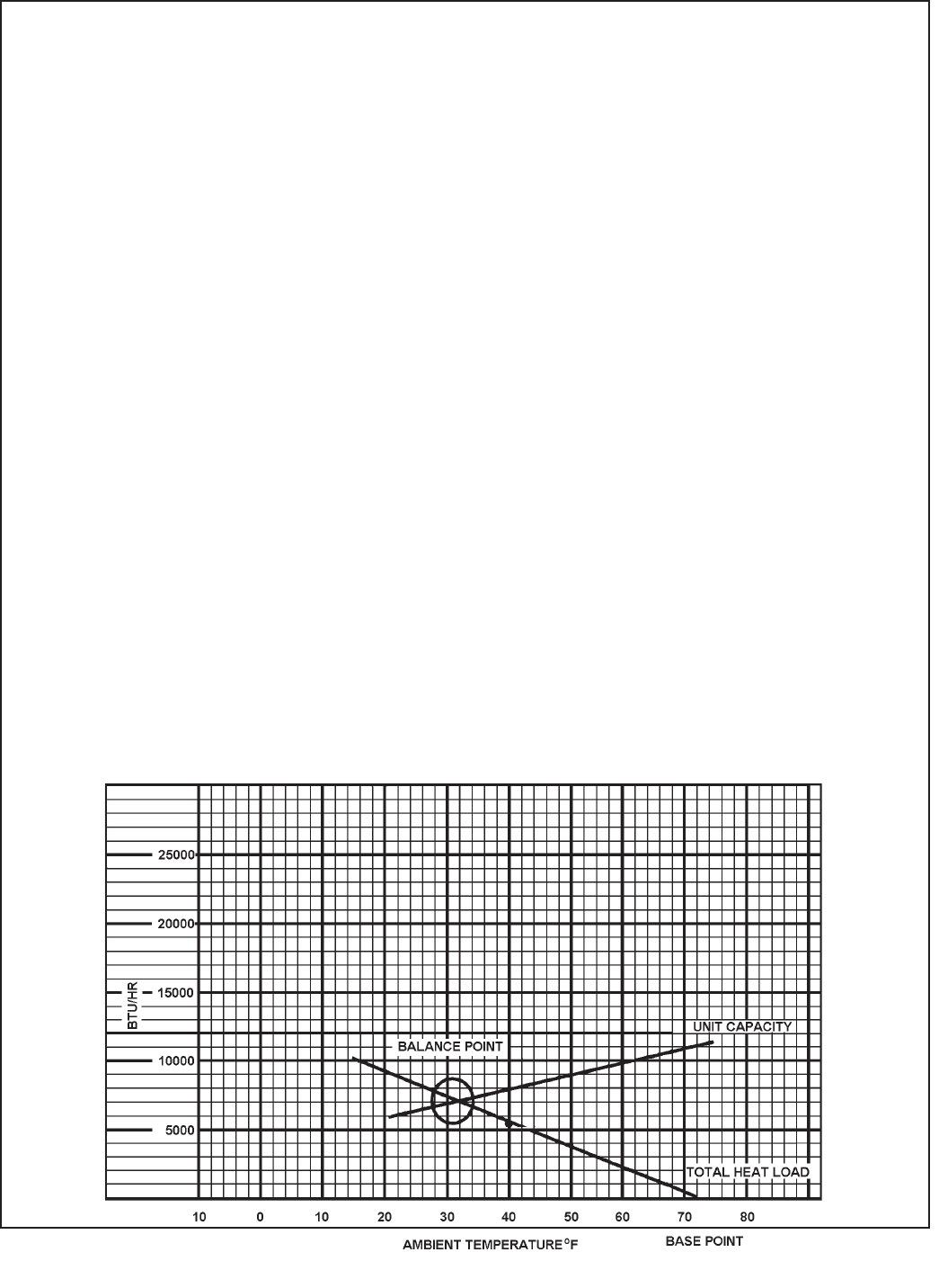
7
HEATING LOAD FORM
FRIEDRICH ROOM UNIT HEAT PUMPS
BTU/HR PER
WALLS: (Linear Feet) °F TEMP. DIFFERENCE
2” Insulation Lin. Ft. x 1.6
Average Lin. Ft. x 2.6
WINDOWS & DOORS (Area, sq. ft.)
Single Glass: Sq. Ft. x 1.13
Double Glass: Sq. Ft. x 0.61
INFILTRATION - WINDOWS & DOORS: AVG. Lin. Ft. x 1.0
Loose Lin. Ft. x 2.0
CEILING: (Area, Sq. Ft.)
Insulated (6”) Sq. Ft. x 0.07
Insulated (2”) Sq. Ft. x 0.10
Built-up Roof (2” insulated Sq. Ft. x 0.10
Built-up Roof (1/2” insulated) Sq. Ft. x 0.20
No Insulation Sq. Ft. x 0.33
FLOOR: (Area, Sq. Ft.)
Above Vented Crawl space
Insulated (1:) Sq. Ft. x 0.20
Uninsulated Sq. Ft. x 0.50
* Slab on Ground Lin. Ft. x 1.70
1” Perimeter insulation Lin. Ft. x 1.00
* Based on Linear Feet of outside wall TOTAL HEAT LOSS PER °F BTU/HR/°F
Multiply total BTU/HR/°F X 30 and plot on the graph below at 40°F. Draw a straight line from
the 70 base point thru the point plotted at 40°F. The intersection of this heat loss line with the
unit capacity line represents the winter design heating load.
62

63
Friedrich Air Conditioning Company
P.O. Box 1540
San Antonio, TX 78295
210.357.4400
www.friedrich.com
ROOM AIR CONDITIONERS
LIMITED WARRANTY
FIRST YEAR
ANY PART: If any part supplied by FRIEDRICH fails because of a defect in workmanship or material within twelve months from
date of original purchase, FRIEDRICH will repair the product at no charge, provided room air conditioner is reasonably accessible
for service. Any additional labor cost for removing inaccessible units and/or charges for mileage related to travel by a Service
Agency that exceeds 25 miles one way will be the responsibility of the owner. This remedy is expressly agreed to be the exclusive
remedy within twelve months from the date of the original purchase.
SECOND THROUGH FIFTH YEAR
SEALED REFRIGERANT SYSTEM: If the Sealed Refrigeration System (defined for this purpose as the compressor, condenser
coil, evaporator coil, reversing valve, check valve, capillary, filter drier, and all interconnecting tubing) supplied by FRIEDRICH in
your Room Air Conditioner fails because of a defect in workmanship or material within sixty months from date of purchase,
FRIEDRICH will pay a labor allowance and parts necessary to repair the Sealed Refrigeration System; PROVIDED FRIEDRICH will
not pay the cost of diagnosis of the problem, removal, freight charges, and transportation of the air conditioner to and from the
Service Agency, and the reinstallation charges associated with repair of the Sealed Refrigeration System. All such cost will be the
sole responsibility of the owner. This remedy is expressly agreed to be the exclusive remedy within sixty months from the date of the
original purchase.
APPLICABILITY AND LIMITATIONS: This warranty is applicable only to units retained within the Fifty States of the U.S.A., District
of Columbia, and Canada. This warranty is not applicable to:
1. Air filters or fuses.
2. Products on which the model and serial numbers have been removed.
3. Products which have defects or damage which results from improper installation, wiring, electrical current
characteristics, or maintenance; or caused by accident, misuse or abuse, fire, flood, alterations and/or misapplication
of the product and/or units installed in a corrosive atmosphere, default or delay in performance caused by war,
government restrictions or restraints, strikes, material shortages beyond the control of FRIEDRICH, or acts of God.
OBTAINING WARRANTY PERFORMANCE: Service will be provided by the FRIEDRICH Authorized Dealer or Service
Organization in your area. They are listed in the Yellow Pages. If assistance is required in obtaining warranty performance, write
to: Room Air Conditioner Service Manager, Friedrich Air Conditioning Co., P.O. Box 1540, San Antonio, TX 78295-1540.
LIMITATIONS: THIS WARRANTY IS GIVEN IN LIEU OF ALL OTHER WARRANTIES. Anything in the warranty
notwithstanding, ANY IMPLIED WARRANTIES OF FITNESS FOR PARTICULAR PURPOSE AND/OR MERCHANTABILITY
SHALL BE LIMITED TO THE DURATION OF THIS EXPRESS WARRANTY. MANUFACTURER EXPRESSLY DISCLAIMS AND
EXCLUDES ANY LIABILITY FOR CONSEQUENTIAL OR INCIDENTAL DAMAGE FOR BREACH OF ANY EXPRESSED OR
IMPLIED WARRANTY.
Performance of Friedrich’s Warranty obligation is limited to one of the following methods:
1. Repair of the unit
2. A refund to the customer for the prorated value of the unit based upon the remaining warranty period of the unit.
3. Providing a replacement unit of equal value
The method of fulfillment of the warranty obligation is at the sole discretion of Friedrich Air Conditioning.
NOTE: Some states do not allow limitations on how long an implied warranty lasts, or do not allow the limitation or exclusion of
consequential or incidental damages, so the foregoing exclusions and limitations may not apply to you.
OTHER: This warranty gives you specific legal rights, and you may also have other rights which vary from state to state.
PROOF OF PURCHASE: Owner must provide proof of purchase in order to receive any warranty related services.
All service calls for explaining the operation of this product will be the sole responsibility of the consumer.
All warranty service must be provided by an Authorized FRIEDRICH Service Agency, unless authorized by FRIEDRICH prior to
repairs being made.
(10-08)

FRIEDRICH AIR CONDITIONING CO.
Post Ofce Box 1540 · San Antonio, Texas 78295-1540
4200 N. Pan Am Expressway · San Antonio, Texas 78218-5212
(210) 357-4400 · FAX (210) 357-4490
www.friedrich.com
Printed in the U.S.A.
TECHNICAL SUPPORT
CONTACT INFORMATION

FRIEDRICH AIR CONDITIONING CO.
Post Ofce Box 1540 · San Antonio, Texas 78295-1540
4200 N. Pan Am Expressway · San Antonio, Texas 78218-5212
(210) 357-4400 · FAX (210) 357-4490
www.friedrich.com
Printed in the U.S.A. RAC-ServMan (04-09)
