Frigidaire FAS156N1A2 User Manual AIR CONDITIONER Manuals And Guides L0523213
FRIGIDAIRE Air Conditioner Room (42) Manual L0523213 FRIGIDAIRE Air Conditioner Room (42) Owner's Manual, FRIGIDAIRE Air Conditioner Room (42) installation guides
User Manual: Frigidaire FAS156N1A2 FAS156N1A2 FRIGIDAIRE AIR CONDITIONER - Manuals and Guides View the owners manual for your FRIGIDAIRE AIR CONDITIONER #FAS156N1A2. Home:Heating & Cooling Parts:Frigidaire Parts:Frigidaire AIR CONDITIONER Manual
Open the PDF directly: View PDF ![]() .
.
Page Count: 8
Installation Instructions
For Heavy Duty
Please read ALL instructions before installing. Two people are
recommended to install this product. Ifa new electrical outlet
is required, have the outlet installed by a qualified electrician
before installing unit. See#5 in Preliminary Instructions
following.
Preliminary Instructions
Do the following before starting to install unit. See illustrations
below.
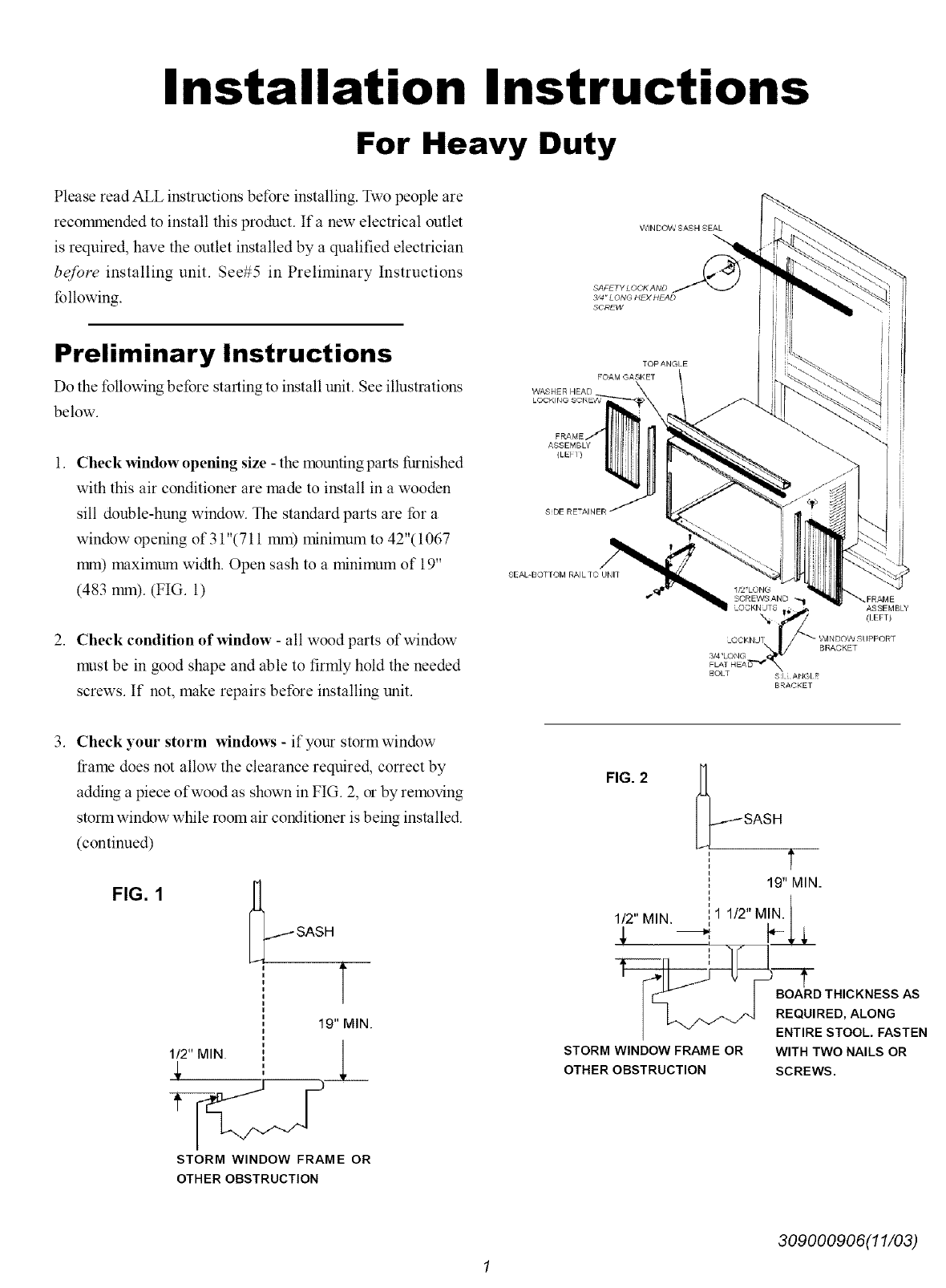
1. Check window opening size - the mounting parts furnished
with this air conditioner are made to install in a wooden
sill double-hung window. The standard parts are for a
window opening of 31 "(711 mm) minimum to 42"( 1067
rc_n) maximum width. Open sash to a minimum of 19"
(483 mm). (FIG. 1)
2. Check condition of window - all wood parts of window
must be in good shape and able to firmly hold the needed
screws. If not, make repairs before installing unit.
WINDOW SASH SEAL
3/4" LONG HE)( HEAD
SCREW
WASHERHEAD
FRAME
ASSEMBLY
(LEII)
SDE RETAINER
SEAL-BOI tOM RAIL TC UNIT
I/2'LOFIG
SCREWS AND "_i FRAME
O_'KN JTS _ ASSEMBLY
\._ _#W-! (lEFT)
OCKNJ [ _ WINDOW _!IPPORT
3/4 'LONG D_____ " BRACKET
BOLT SI ANGI
BRACKET
3. Check your storm windows -if your storm window
frame does not allow the clearance required, correct by
adding a piece of wood as shown in FIG. 2, or by removing
storm window while room air conditioner is being installed.
(continued)
FIG. 1
_ SASH T
19" MIN.
STORM WINDOW FRAME OR
OTHER OBSTRUCTION
FIG. 2[_SASH
1
19" MIN_
112"MIN 1 1/2"MIN.
ENTIRE STOOL. FASTEN
STORM WINDOW FRAME OR WITH TWO NAILS OR
OTHER OBSTRUCTION SCREWS.
309000906(11/03)
4. CHECK FOR ANYTHING THAT COULD BLOCK
AIRFLOW -check area outside of window for things
such as shrubs, trees, or awnings. Inside, be sure
furniture, drapes, or blinds will not stop proper airflow.
5. Check the available electrical service -power supply must
be the same as that shown on the unit serial nameplate.
(See Owner's Guide for serial plate location.) Power cord
is 48"long. Be sure you have an outlet near.
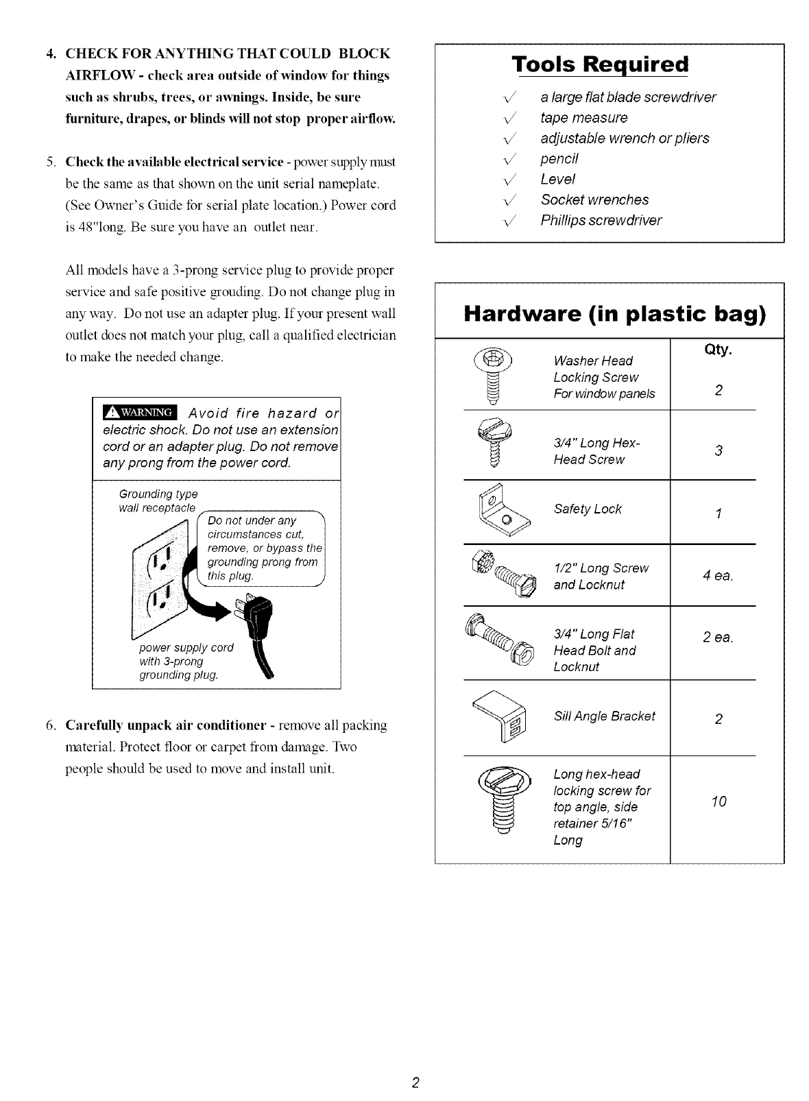
Tools Required
a large flat blade screwdriver
tape measure
adjustable wrench or pliers
pencil
Level
Socket wrenches
Phillips screwdriver
All models have a 3-prong service plug to provide proper
service and safe positive grouding. Do not change plug in
any way. Do not use an adapter plug. If your present wall
outlet does not match your plug, call a qualified electrician
to make the needed change.
Avoid fire hazard or
electric shock. Do not use an extension
cord or an adapter plug. Do not remove
any prong from the power cord.
Grounding type
wall receptacle
/_, tl circumstancescut,I
r" _ _ remove,orbypasstheI
I(l', lP groundingprongfromI
power supply cord_
with 3-prong
grounding plug.
6. Carefully unpack air conditioner - remove all packing
material. Protect floor or carpet from damage. Two
people should be used to move and install unit.
Hardware (in plastic bag)
Washer Head
Locking Screw
For window panels
3/4 Long Hex-
ft
Head Screw
Safety Lock
@_ 1/2"LongScrew
and Locknut
%_ 3/4" Long FlatHead Bolt and
Locknut
Sill Angle Bracket
Long hex-head
locking screw for
top angle, side
retainer 5/16"
Long
4 ea.
2ea.
10
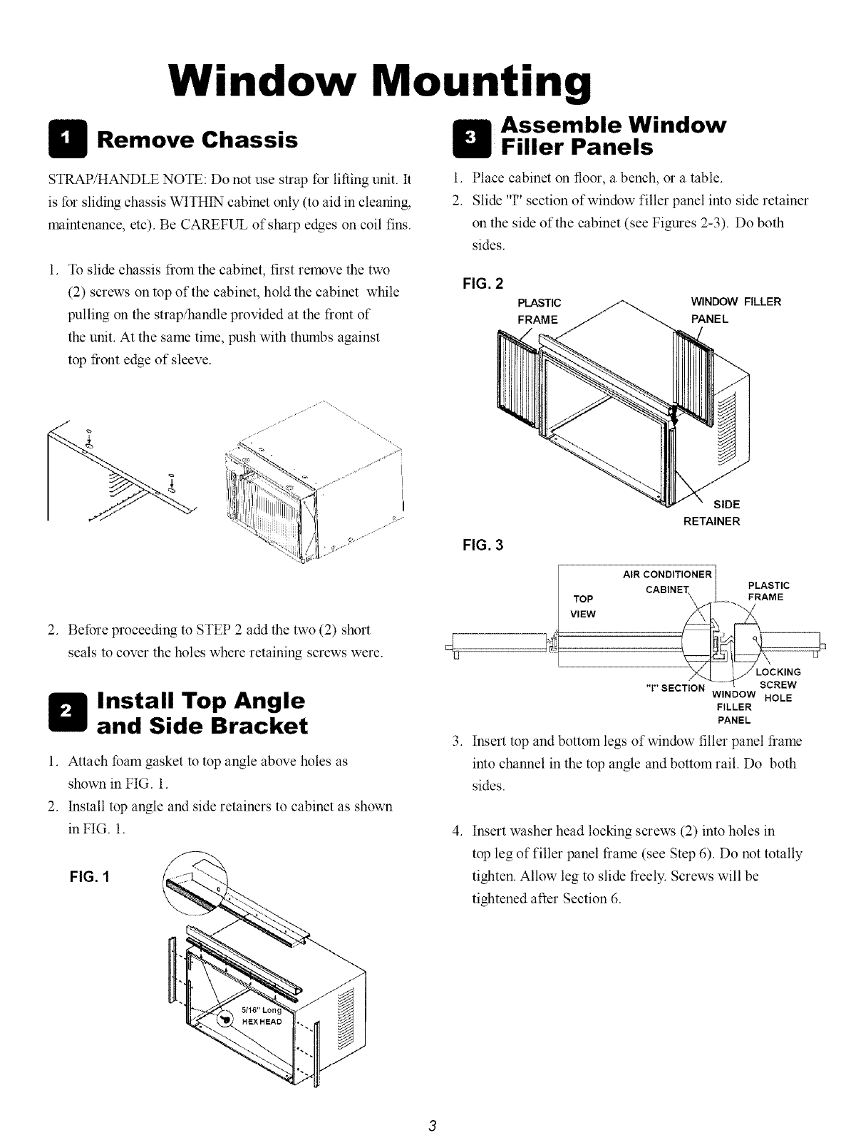
Window Mounting
Assemble Window
Remove Chassis Filler Panels
STRAP/HANDLE NOTE: Do not use strap for lifting unit. It
is for sliding chassis WITHIN cabinet only (to aid in cleaning,
maintenance, etc). Be CAREFUL of sharp edges on coil fins.
1. Place cabinet on floor, a bench, or a table.
2. Slide 'T' section of window filler panel into side retainer
on the side of the cabinet (see Figures 2-3). Do both
sides.
1. To slide chassis from the cabinet, first remove the two
(2) screws on top of the cabinet, hold the cabinet while
pulling on the strap/handle provided at the front of
the unit. At the same time, push with thumbs against
top front edge of sleeve.
FIG. 2
PLASTIC WINDOW FILLER
FRAME PANEL
T'h"_-_ ~_%..... !i
ii:ii!!!!!iiil]'i/i:i['_l I
,= <_ji=t .=
2. Before proceeding to STEP 2 add the two (2) short
seals to cover the holes where retaining screws were.
Install Top Angle
and Side Bracket
1. Attach foam gasket to top angle above holes as
shown in FIG. 1.
2. Install top angle and side retainers to cabinet as shown
in FIG. 1.
FIG. 1
.
FIG. 3
SIDE
RETAINER
AIR CONDITIONER
CABINI _PLASTI
TOP ...... FRAME
Vl EW
'T' SECTION WINDOW HOLE
FILLER
PANEL
Insert top and bottom legs of window filler panel frame
into channel in the top angle and bottom rail. Do both
sides.
.Insert washer head locking screws (2) into holes in
top leg of filler panel frame (see Step 6). Do not totally
tighten. Allow leg to slide freely. Screws will be
tightened after Section 6.
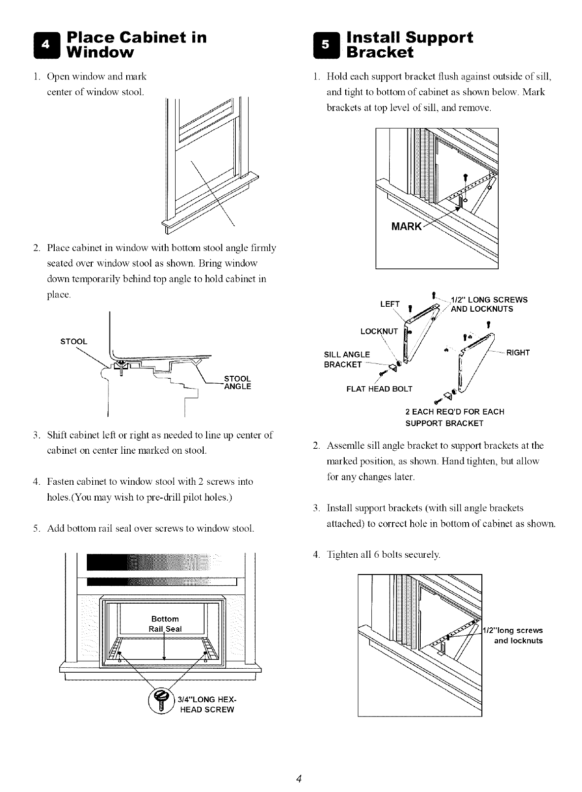
Place Cabinet in
Window
1. Open window and mark
center of window stool.
2. Place cabinet in window with bottom stool angle firmly
seated over window stool as shown. Bring window
down temporarily behind top angle to hold cabinet in
place.
3. Shift cabinet left or right as needed to line up center of
cabinet on center line marked on stool.
4. Fasten cabinet to window stool with 2 screws into
holes.(You may wish to pre-drill pilot holes.)
5. Add bottom rail seal over screws to window stool.
Install Support
Bracket
1. Hold each support bracket flush against outside of sill,
and tight to bottom of cabinet as shown below. Mark
brackets at top level of sill, and remove.
4
MARK
|........ 1/2" LONG SCREWS
LEFT\. _/AND LOCKNUTS
LOC UTg" ,. !
FLAT HEAD BOLT <_@b,_/
2 EACH REQ'D FOR EACH
SUPPORT BRACKET
2. Assemlle sill angle bracket to support brackets at the
marked position, as shown. Hand tighten, but allow
for any changes later.
3. Install support brackets (with sill angle brackets
attached) to correct hole in bottom of cabinet as shown.
I
LBottom
Rail Seal
_\. ./
"\ // --
I(_/_/_//3/4"LONG HEX- I
_.._/HEADSCREW
4. Tighten all 6 bolts securely.
l/2"long screws
andlocknuts
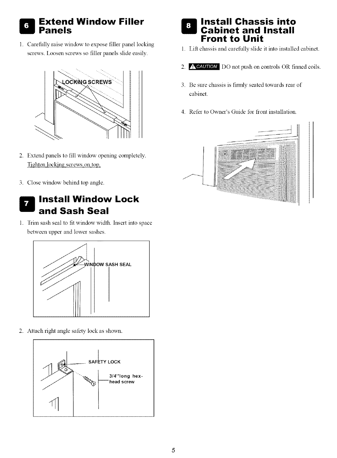
Extend Window Filler
Panels
1. Carefully raise window to expose filler panel locking
screws. Loosen screws so filler panels slide easily.
Install Chassis into
Cabinet and Install
Front to Unit
1. Lift chassis and carefully slide it into installed cabinet.
2. _ DO not push on controls OR finned coils.
3. Be sure chassis is firmly seated towards rear of
cabinet.
4. Refer to Owner's Guide for front installation.
2. Extend panels to fill window opening completely.
Tighten lockin_ screws on top.
3. Close window behind top angle.
Install Window Lock
and Sash Seal
1. Trim sash seal to fit window width. Insert into space
between upper and lower sashes.
)OW SASH SEAL
2. Attach right angle safety lock as shown.
/_ y ---_. 3,4",onghex-
"/// _) -- head screw
Thru-The-Wall Installation
NOTE: Consult local building codes prior to installation,
or a qualified carpenter.
Carefully measure and cut an opening with t he following
dimensions. See FIGS. 1 and 2.
Select Wall Location
This air conditioner has a slide-out chassis, so it canbe installed
through an outside wall up to 12" thick. IMPORTANT: Side
louvers must never be blocked.
NOTE: All parts neede for Thru-The-Wall Installation are
provided, except a wood frame, shims, and 10 wood screws (#
10-1" long minimum). Select a wall surface that:
1. does not support major structural loads such as the frame
construction at ends of windows, and under truss-bearing
points, etc.
2. does not have plumbing or wiring inside.
3. is near existing electrical outlets, or where another outlet
can be installed.
4. Paces, and is not blocked to the area to be cooled.
5. allows unblocked airflow from rear sides and end (outside)
of installed air conditioner.
Prepare Wall
1. Prepare wall in frame construction (including brick and
stucco veneer). Working from inside the room, find wall
stud nearest the center of area where air conditioner will
be installed (by sounding wall, or by magnetically inding
nails).
2. Cut or knock out a hole on each side of center stud.
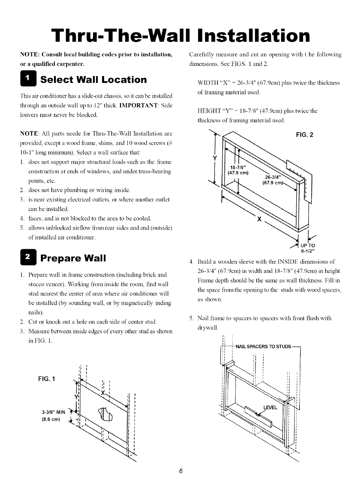
3. Measure between inside edges ofeve_ T other stud as shown
in FIG. 1.
WIDTH "X" = 26-3/4" (67.9cm) plus twice the thickness
of framing material used.
HEIGHT "Y" = 18-7/8" (47.9cm) plus twice the
thickness of fiaming material used.
Y
FIG. 2
UP TO
8-1/2"
4. Build a wooden sleeve with the INSIDE dimensions of
26-3/4" (67.9cm) in width and 18-7/8" (47.9cm) in height.
Frame depth should be the same as wall thickness. Fill in
the space from the opening to the studs with wood spacers,
as shown.
5. Nail frame to spacers to spacers with front flush with
drywall.
IE
FIG. 1
3-3/8" MIN
(8.6 cm)

NOTE: If wall thickness is 8-1/2" or more, add aluminum
flashing over bottom of frame opening to assure no water can
enter area between inner and outer wall.
1" LONG
WOOD SCREW
FIG. 2
OPTIONAL: Support brackets may be used. Installation
brakcets are recommended for walls under 5" thick.
ALUMINUM FLASHING
OVER BOTTOM OF FRAME
OVER
81/2"
Refer to Step 4 of Window Mounting for assembly of support
brackets. A wooden strip nailed to the outside wall should be
used in coniunction with sill support angle brackets.
Prepare and Install
Cabinet
I. Slide chassis from cabinet. Refer back to Step l of
Window Mounting.
2. Place cabinet into opening with bottom rail resting firmly
on bottom board of wooden frame.
3. Position cabinet to achieve proper slope for water removal.
(See FIG. 1 below.)
FIG. 1
3/4" PLUS
THICKNESS
SEE PARA 5
TO
3/8"
F"
LEVEL
brakcet
Wooden strip
5. Screw or nail cabinet wooden frame using shims if frame
is oversized, to eliminate distortion. Remember to maintain
proper slope as described in Step 3.
4. Secure bottom rail to wood frame with two large wood
screws 1"(2.5 cm) long using the tow holes in the bottom
of the channel resting on frame. (See FIG. 2 following) 6. Install chassis into cabinet by following all steps in Step
8 of Window Mounting. (continued)
OPTIONAL: Caulking and installation of trim on interior wall
may be done. You can buy wood from your local lumber or
hardware supply. On the outside, caulk openings around top
and sides of cabinet, and all sides ofwtx_d sleeve to the opening.
NOTE: See Step 7, Item 3 of Window Mounting Instructions
for bottom rail seal location.
Masonry Construction
1. Cut or build a wall opening in the masonry wall similar
to the frame construction (refer to Step 2 of Tbau-the-
Wall Installation for a wall thickness _eater than 8-1/
2").
2. Secure cabinet in place using masom 7 nails, or the right
masom 7 anchor screws. (Another way to do this is to build
an in-between frame of 2x4's as shown in the Step 2 Prepare
Wall illustrations-but make it double framed on either
side, and install between n_soru 7 wall opening and cabinet.
Frame must be securely anchored to masom 7 wall
opening) This way gives very good louver clearance on
either side of cabinet.
3. Install a lintel to support masom 7 wall above cabinet.
Existing holes in cabinet can be used and/or additional
holes can be &illed to fasten cabinet at various positions.
Be sure that side louver clearance is in accordance with
Step 1 above.
4. Install exterior cabient support brackets as shown in
Step 2 of Tinu-the-Wall Installation. Caulk or flash if
nee&, to provide a wether-tight seal around top and
sides of cabinet.
5. To complete installation, apply wood trim molding
around room side projection of cabinet.
