Frigidaire FCFS201LFB3 User Manual FREEZER Manuals And Guides L0609487
FRIGIDAIRE Refrigeration Commercial Manual L0609487 FRIGIDAIRE Refrigeration Commercial Owner's Manual, FRIGIDAIRE Refrigeration Commercial installation guides
User Manual: Frigidaire FCFS201LFB3 FCFS201LFB3 FRIGIDAIRE FREEZER - Manuals and Guides View the owners manual for your FRIGIDAIRE FREEZER #FCFS201LFB3. Home:Kitchen Appliance Parts:Frigidaire Parts:Frigidaire FREEZER Manual
Open the PDF directly: View PDF ![]() .
.
Page Count: 11
FRIGIDAIRE
COMMERCIAL
COMMERCIAL FREEZER/REFRIGERATOR
GLASS DOOR REFRIGERATOR
TABLE OF CONTENTS
Product Registration ................................................ 2
Important Safety Instructions .................................... 2
Electrical Information ............................................... 3
Caster Installation and Setup (Glass Door) ................... 3-4
Caster Installation and Setup (Non-Glass Door) .......... 5-6
Appliance Start-up .................................................... 6
Features ................................................................. 6-7
Routine Maintenance ............................................... 7
Energy Conservation Measures ................................. 7
Troubleshooting Guide ............................................. 8-9
Wiring Diagram ....................................................... 10
Warranty ............................................................... 11
READ AND SAVE THESE INSTRUCTIONS 297121600(June2006)
Product Registration
y!_v_vf£q_ll_[€
These instructions include information which is intended to
assure the operator of correct installation, operation and service.
Before attempting installation, adjustment or maintenance, be
certain of the following:
• That you have read and fully understand the instructions.
• That you have all the tools required and are trained to use
them.
• That you have met all installation and usage restrictions and
are familiar with the functions and operations of the unit.
• That you follow all instructions exactly as given.
_v_vf_4_]#II#B
All the fittings, measurements, recommendations and procedures
are significant. Substitutions and approximations must be
avoided, improper handling, maintenance, installation and
adjustment, or service attempted by anyone other than a qualified
technician, may void the future warranty claims and cause
damage to the unit and/or result in injury to the operator and/or
bystanders.
Important Safety Instructions
Read all instructions before using this appliance
For Your SafetyL,_wm_dl_
Do not store or use gasoline or other flammable vapors and
liquids in the vicinity of this unit or any other appliance. Read
product labels for flammability and other warnings.
Child Safety
• Destroy carton, plastic bags, and any exterior wrapping material
immediately after the appliance is unpacked. Children should
never use these items for play. Cartons covered with rugs,
bedspreads, plastic sheets or stretch wrap may become airtight
chambers and can quickly cause suffocation.
•A child might suffocate if he crawls into the appliance to hide
or play. Remove the door/lid of the appliance when not in use,
even if you plan to discard the appliance. Many communities
have laws requiring you to take this safety precaution.
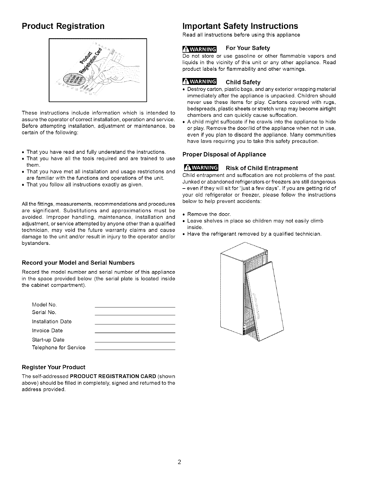
Proper Disposal of Appliance
Risk of Child Entrapment
Child entrapment and suffocation are not problems of the past.
Junked or abandoned refrigerators or freezers are still dangerous
- even if they will sit for "just a few days". If you are getting rid of
your old refrigerator or freezer, please follow the instructions
below to help prevent accidents:
• Remove the door.
• Leave shelves in place so children may not easily climb
inside.
• Have the refrigerant removed by a qualified technician.
Record your Model and Serial Numbers
Record the model number and serial number of this appliance
in the space provided below (the serial plate is located inside
the cabinet compartment).
Model No.
Serial No.
Installation Date
Invoice Date
Start-up Date
Telephone for Service
Register Your Product
The self-addressed PRODUCT REGISTRATION CARD (shown
above) should be filled in completely, signed and returned to the
address provided.
Electrical Information
These guidelines must be followed to ensure that safety
mechanisms in the design of this appliance will operate
properly.
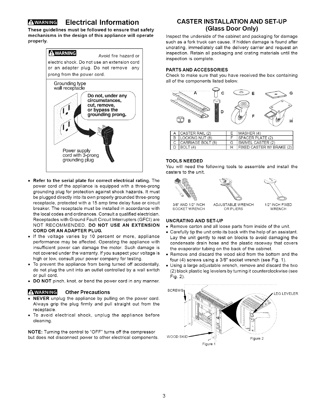
Avoid fire hazard or
electric shock. Do not use an extension cord
or an adapter plug. Do not remove any
prong from the power cord.
Grounding type
walmreceptacle
Power suppmy
cord with 3-prong
grounding pmug
• Refer to the serial plate for correct electrical rating. The
power cord of the appliance is equipped with a three-prong
grounding plug for protection against shock hazards. It must
be plugged directly into its own properly grounded three-prong
receptacle, protected with a 15 amp time delay fuse or circuit
breaker. The receptacle must be installed in accordance with
the local codes and ordinances. Consult a qualified electrician.
Receptacles with Ground Fault Circuit Interrupters (GFCI) are
NOT RECOMMENDED. DO NOT USE AN EXTENSION
CORD OR AN ADAPTER PLUG.
• If the voltage varies by 10 percent or more, appliance
performance may be affected. Operating the appliance with
insufficient power can damage the motor. Such damage is
not covered under the warranty. If you suspect your voltage is
high or low, consult your power company for testing.
• To prevent the appliance from being turned off accidentally,
do not plug the unit into an outlet controlled by a wall switch
or pull cord.
• DO NOT pinch, knot, or bend the power cord in any manner.
Other Precautions
• NEVER unplug the appliance by pulling on the power cord.
Always grip the plug firmly and pull straight out from the
receptacle.
• To avoid electrical shock, unplug the appliance before
cleaning.
NOTE: Turning the control to "OFF" turns off the compressor
but does not disconnect power to other electrical components.
CASTER INSTALLATION AND SET-UP
(Glass Door Only)
inspect the underside of the cabinet and packaging for damage
such as a fork truck can cause. If hidden damage is found after
uncrating, immediately call the delivery carrier and request an
inspection. Retain all packaging and crating materials until the
inspection is complete.
PARTS AND ACCESSORIES
Check to make sure that you have received the box containing
all of the components listed below.
A CASTER RAiL (2) E WASHER (4)
B LOCKING NUT (8) F SPACER PLATE (2)
C CARRIAGE BOLT (8) G SWIVEL CASTER (2)
D BOLT (4) H FIXED CASTER W/ BRAKE (2)
TOOLS NEEDED
You will need the following tools to assemble and install the
casters to the unit.
3/8" AND 1/2" INCH ADJUSTABLE WRENCH
SOCKET WRENCH OR PLIERS
1/2" INCH FIXED
WRENCH
UNCRATING AND SET-UP
• Remove carton and all loose parts from inside of the unit.
• Carefully tip the unit onto its back with the help of an assistant.
Lay the unit gently to rest on blocks to avoid damaging the
condensate drain hose and the plastic raceway that covers
the evaporator tubing on the back of the cabinet.
• Remove and discard the wood skid from the bottom and the
four (4) screws using a 3/8" socket wrench (see Fig. 1).
• Using a large adjustable wrench, remove and discard the two
(2) black plastic leg levelers by turning it counterclockwise (see
Fig. 2).
jl
SCREWS LEG LEVELER
i!i
Figure 2
Figure 1
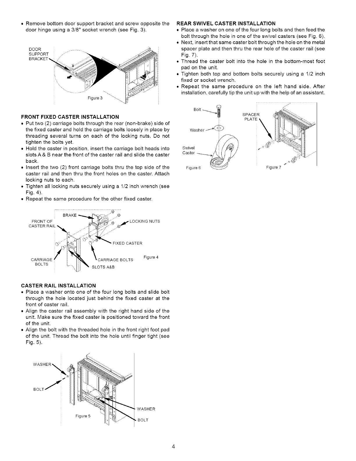
• Remove bottom door support bracket and screw opposite the
door hinge using a 3/8" socket wrench (see Fig. 3).
DOOR
Figure 3 "\
FRONT FIXED CASTER INSTALLATION
• Put two (2) carriage bolts through the rear (non-brake) side of
the fixed caster and hold the carriage bolts loosely in place by
threading several turns on each of the locking nuts. Do not
tighten the bolts yet.
• Hold the caster in position, insert the carriage bolt heads into
slots A & B near the front of the caster rail and slide the caster
back.
• Insert the two (2) front carriage bolts thru the top side of the
caster rail and then thru the front holes on the caster. Attach
locking nuts to each.
• Tighten all locking nuts securely using a 1/2 inch wrench (see
Fig. 4).
• Repeat the same procedure for the other fixed caster.
BRAKE _9
FRONT OF NUTS
FIXED CASTER
REAR SWIVEL CASTER INSTALLATION
• Place a washer on one of the four long bolts and then feed the
bolt through the hole in one of the swivel casters (see Fig. 6).
• Next, insert that same caster bolt through the hole on the metal
spacer plate and then thru the rear hole of the caster rail (see
Fig. 7).
• Thread the caster bolt into the hole in the bottom-most foot
pad on the unit.
• Tighten both top and bottom bolts securely using a 1/2 inch
fixed or socket wrench.
• Repeat the same procedure on the left hand side. After
installation, carefully tip the unit up with the help of an assistant.
Bolt .-__ ._
i
Washe r .7_c_b
i
Swivel +_+_
Caster ....
Figure 6
j/
Figure 7
CARRIAGE
BOLTS SLOTS A&B
Figure 4
CASTER RAIL INSTALLATION
• Place a washer onto one of the four long bolts and slide bolt
through the hole located just behind the fixed caster at the
front of caster rail.
• Align the caster rail assembly with the right hand side of the
unit. Make sure the fixed caster is positioned toward the front
of the unit.
• Align the bolt with the threaded hole in the front right foot pad
of the unit. Thread the bolt into the hole until finger tight (see
Fig. 5).
WASHER_
BOLT /
Figure 5
WASHER
,BOLT
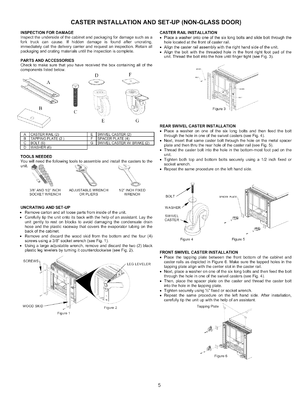
CASTER INSTALLATION AND SET-UP (NON-GLASS DOOR)
INSPECTION FOR DAMAGE
Inspect the underside of the cabinet and packaging for damage such as a
fork truck can cause. If hidden damage is found after uncrating,
immediately call the delivery carrier and request an inspection. Retain all
packaging and crating materials until the inspection is complete.
PARTS AND ACCESSORIES
Check to make sure that you have received the box containing all of the
components listed below.
D F
!
.7--- E G
A CASTER RAIL (2) E SWIVEL CASTER (2)
a TAPPING PLATE (2) F SPACER PLATE (4)
C BOLT (6) G SW VEL CASTER W/BRAKE (2
D WASHER (6)
TOOLS NEEDED
You will need the following tools to assemble and install the casters to the
unit.
3/8" AND 1/2" INCH ADJUSTABLE WRENCH
SOCKET WRENCH OR PLIERS
1/2" INCH FIXED
WRENCH
CASTER RAIL INSTALLATION
=Place a washer onto one of the six long bolts and slide bolt through the
hole located at the front of caster rail.
• Align the caster rail assembly with the right hand side of the unit.
• Align the bolt with the threaded hole in the front right foot pad of the
unit. Thread the bolt into the hole until finger tight (see Fig. 3).
>J I .....
Figure 3 :'.-
REAR SWIVEL CASTER INSTALLATION
•Place a washer on one of the six long bolts and then feed the bolt
through the hole in one of the swivel casters (see Fig. 4).
•Next, insert that same caster bolt through the hole on the metal spacer
plate and then thru the rear hole of the caster rail (see Fig. 5).
•Thread the caster bolt into the hole in the bottom-most foot pad on the
unit.
• Tighten both top and bottom bolts securely using a 1/2 inch fixed or
socket wrench.
•Repeat the same procedure on the left hand side.
UNCRATING AND SET-UP
•Remove carton and all loose parts from inside of the unit.
• Carefully tip the unit onto its back with the help of an assistant. Lay the
unit gently to rest on blocks to avoid damaging the condensate drain
hose and the plastic raceway that covers the evaporator tubing on the
back of the cabinet
• Remove and discard the wood skid from the bottom and the four (4)
screws using a 3/8" socket wrench (see Fig 1 ).
• Using a large adjustable wrench, remove and discard the two (2) black
plastic leg levelers by turning it counterclockwise (see Fig 2)
SCREWS ,LEG LEVELER
WOOD SKID
Figure 1
Figure 2
Figure 4 Figure 5
FRONT SWIVEL CASTER INSTALLATION
• Place the tapping plate between the front bottom of the cabinet and
caster rails as depicted in Figure 6. Make sure the tapped holes in the
tapping plate align with the center slot in the caster rail.
• Next, place a washer on one of the six long bolts and then feed the bolt
through the hole in one of the swivel casters (see Fig. 4).
• Then, place the spacer plate on the caster and thread the caster bolt
into the hole in the tapping plate.
• Tighten securely using ½" fixed or socket wrench.
• Repeat the same procedure on the left hand side. After installation,
carefully tip the unit up with the help of an assistant.
Tapping Plate .........
Appliance Placement
Leave a one (1) inch space on all sides and the back of the
cabinet for ease of installation, proper air circulation and electrical
connections. DO NOT block the front grill on the lower front
of your appliance. Sufficient air circulation is essential for the
proper operation of your appliance. Choose a place that is near
a grounded electrical outlet. For the most efficient operation,
the appliance should be located where surrounding temperatures
will not drop below 4O°F (5°C) or exceed 110°F (43°C). Additional
compressor heaters are not recommended.
Insulation
The insulated space of this cabinet is sealed to maintain peak
efficiency. Holes drilled in the cabinet may destroy that seal and
damage electrical wiring located in the insulated space.
DAMANGED ELECTRICAL WIRING OR WET INSULATION
CAUSED BY DRILLING WILL VOID THE WARRANTY.
Appliance Start-up
Once the appliance has been located in its permanent location
and the proper power and grounding has been provided, the
following items must be checked or completed:
Cool Down Period
For safe food storage, allow 24 hours for the appliance to cool
down completely before loading with food. The appliance will
run continuously for the first several hours. Do not place any
food in the appliance until after the first 24 hours of operation.
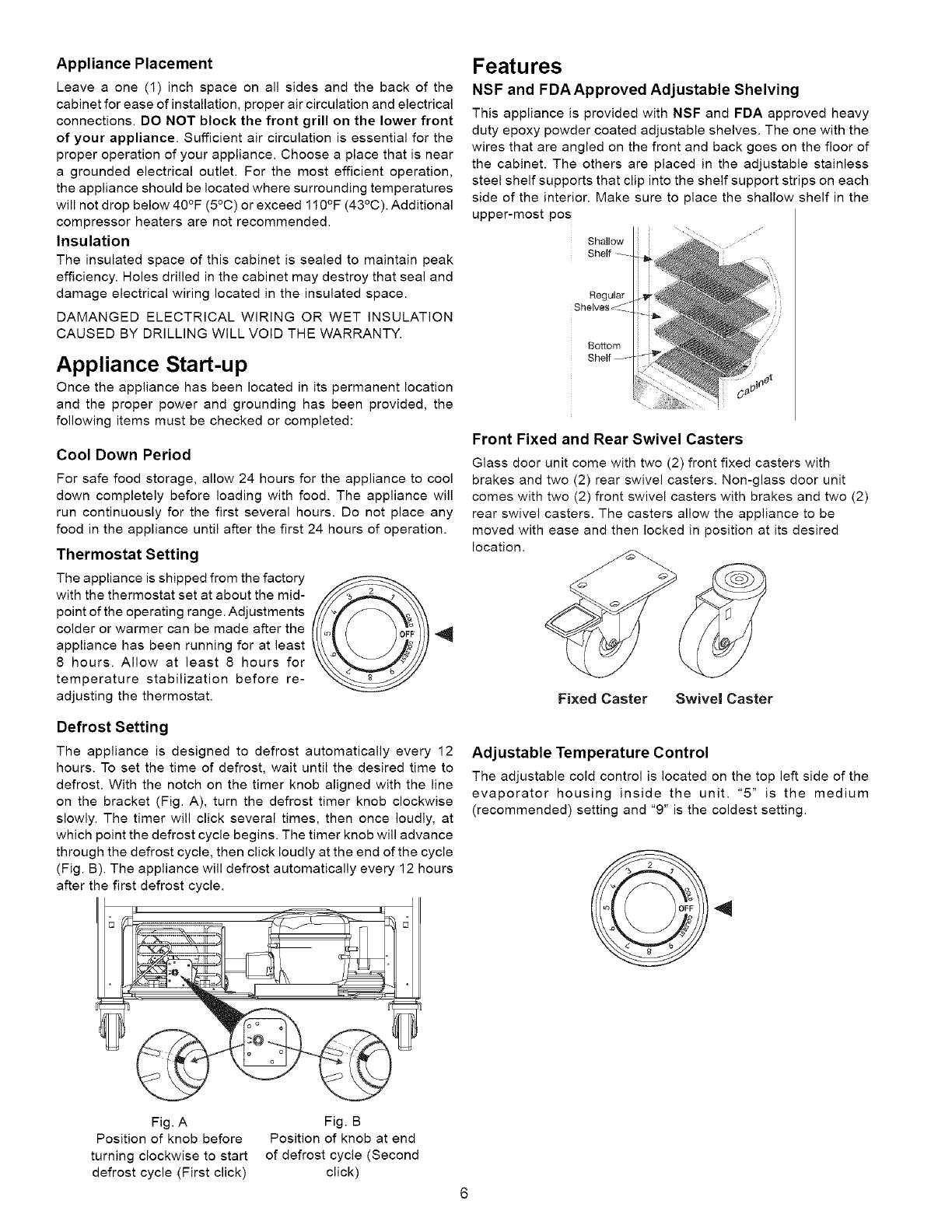
Thermostat Setting
The appliance is shipped from the factory
with the thermostat set at about the mid-
point of the operating range. Adjustments
colder or warmer can be made after the
appliance has been running for at least
8 hours. Allow at least 8 hours for
temperature stabilization before re-
adjusting the thermostat.
Defrost Setting
The appliance is designed to defrost automatically every 12
hours. To set the time of defrost, wait until the desired time to
defrost. With the notch on the timer knob aligned with the line
on the bracket (Fig. A), turn the defrost timer knob clockwise
slowly. The timer will click several times, then once loudly, at
which point the defrost cycle begins. The timer knob will advance
through the defrost cycle, then click loudly at the end of the cycle
(Fig. B). The appliance will defrost automatically every 12 hours
after the first defrost cycle.
Features
NSF and FDAApproved Adjustable Shelving
This appliance is provided with NSF and FDA approved heavy
duty epoxy powder coated adjustable shelves. The one with the
wires that are angled on the front and back goes on the floor of
the cabinet. The others are placed in the adjustable stainless
steel shelf supports that clip into the shelf support strips on each
side of the interior. Make sure to place the shallow shelf in the
upper-most pos
Shallow
Regular
BoSom
Front Fixed and Rear Swivel Casters
Glass door unit come with two (2) front fixed casters with
brakes and two (2) rear swivel casters. Non-glass door unit
comes with two (2) front swivel casters with brakes and two (2)
rear swivel casters. The casters allow the appliance to be
moved with ease and then locked in position at its desired
location.
Fixed Caster Swivel Caster
Adjustable Temperature Control
The adjustable cold control is located on the top left side of the
evaporator housing inside the unit. "5" is the medium
(recommended) setting and "9" is the coldest setting.
Fig. A
Position of knob before
turning clockwise to start
defrost cycle (First click)
Fig. B
Position of knob at end
of defrost cycle (Second
click)
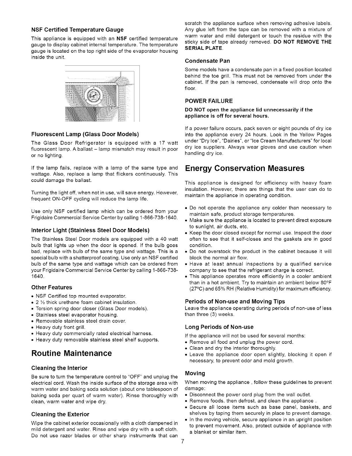
NSF Certified Temperature Gauge
This appliance is equipped with an NSF certified temperature
gauge to display cabinet internal temperature. The temperature
gauge is located on the top right side of the evaporator housing
inside the unit.
scratch the appliance surface when removing adhesive labels.
Any glue left from the tape can be removed with a mixture of
warm water and mild detergent or touch the residue with the
sticky side of tape already removed. DO NOT REMOVE THE
SERIAL PLATE.
Condensate Pan
Some models have a condensate pan in a fixed position located
behind the toe grill. This must not be removed from under the
cabinet. If the pan is removed, condensate will drop onto the
floor.
POWER FAILURE
DO NOT open the appliance lid unnecessarily if the
appliance is off for several hours.
Fluorescent Lamp (Glass Door Models)
The Glass Door Refrigerator is equipped with a 17 watt
fluorescent lamp. A ballast - lamp mismatch may result in poor
or no lighting.
If a power failure occurs, pack seven or eight pounds of dry ice
into the appliance every 24 hours. Look in the Yellow Pages
under "Dry Ice", "Dairies", or "Ice Cream Manufacturers" for local
dry ice suppliers. Always wear gloves and use caution when
handling dry ice.
If the lamp fails, replace with a lamp of the same type and
wattage. Also, replace a lamp that flickers continuously. This
could damage the ballast.
Turning the light off, when not in use, will save energy. However,
frequent ON-OFF cycling will reduce the lamp life.
Use only NSF certified lamp which can be ordered from your
Frigidaire Commercial Service Center by calling 1-866-738-1640.
Interior Light (Stainless Steel Door Models)
The Stainless Steel Door models are equipped with a 40 watt
bulb that lights up when the door is opened. If the bulb goes
bad, replace with bulb of the same type and wattage. This is a
special bulb with a shatterproof coating. Use only an NSF certified
bulb of the same type and wattage which can be ordered from
your Frigidaire Commercial Service Center by calling 1-866-738-
1640.
Other Features
• NSF Certified top mounted evaporator.
• 2 ½ thick urethane foam cabinet insulation.
• Torsion spring door closer (Glass Door models).
• Stainless steel evaporator housing.
• Removable stainless steel drain cover.
• Heavy duty front grill.
• Heavy duty commercially rated electrical harness.
• Heavy duty removable stainless steel shelf supports.
Routine Maintenance
Cleaning the Interior
Be sure to turn the temperature control to "OFF" and unplug the
electrical cord. Wash the inside surface of the storage area with
warm water and baking soda solution (about one tablespoon of
baking soda per quart of warm water). Rinse thoroughly with
clean, warm water and wipe dry.
Cleaning the Exterior
Wipe the cabinet exterior occasionally with a cloth dampened in
mild detergent and water. Rinse and wipe dry with a soft cloth.
Do not use razor blades or other sharp instruments that can
Energy Conservation Measures
This appliance is designed for efficiency with heavy foam
insulation. However, there are things that the user can do to
maintain the appliance in operating condition.
• Do not operate the appliance any colder than necessary to
maintain safe, product storage temperatures.
• Make sure the appliance is located to prevent direct exposure
to sunlight, air ducts, etc.
• Keep the door closed except for normal use. Inspect the door
often to see that it self-closes and the gaskets are in good
condition.
• Do not overstock the product in the cabinet because it will
block the normal air flow.
• Have at least annual inspections by a qualified service
company to see that the refrigerant charge is correct.
• This appliance operates more efficiently in a cooler ambient
than in a hot ambient. Try to maintain an ambient below 80°F
(27°C) and 65% RH (Relative Humidity) for maximum efficiency.
Periods of Non-use and Moving Tips
Leave the appliance operating during periods of non-use of less
than three (3) weeks.
Long Periods of Non-use
If the appliance will not be used for several months:
• Remove all food and unplug the power cord.
• Clean and dry the interior thoroughly.
• Leave the appliance door open slightly, blocking it open if
necessary, to prevent odor and mold growth.
Moving
When moving the appliance, follow these guidelines to prevent
damage:
• Disconnect the power cord plug from the wall outlet.
• Remove foods, then defrost, and clean the appliance .
• Secure all loose items such as base panel, baskets, and
shelves by taping them securely in place to prevent damage.
• In the moving vehicle, secure appliance in an upright position
to prevent movement. Also, protect outside of appliance with
a blanket or similar item.
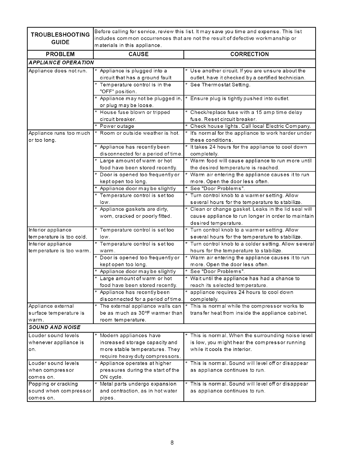
TROUBLESHOOTING
GUIDE
PROBLEM
A PPLIA NCE OPERA TION
Appliance does not run. *
Appliance runs too much *
or too long.
Interior appliance *
temperature is too cold.
interior appliance *
temperature is too warm.
Appliance external *
surface temperature is
warm.
SOUND AND NOISE
Louder sound levels *
whenever appliance is
On.
Before calling for service, review this list. It may save you time and expense. This list
includes common occurrences that are not the result of defective workmanship or
materials in this appliance.
CAUSE
Appliance is plugged into a
circuit that has a ground fault
Temperature control is in the
"OFF" position.
Appliance may not be plugged in,
or plug maybe loose.
House fuse blown or tripped
circuit breaker.
Power outage
Room or outside weather is hot.
Appliance has recently been
disconnected for a period of time.
Large amount ofwarm or hot
food have been stored recently.
Door is opened too frequentlyor
kept open too long.
Appliance door may be slightly
Temperature control is set too
low.
Appliance gaskets are dirty,
worn, cracked or poorly fitted.
Temperature control is set too
low.
Temperature control is set too
warm.
Door is opened too frequentlyor
kept open too long.
Appliance door may be slightly
Large amount of warm or hot
food have been stored recently.
Appliance has recently been
disconnected for a period of time.
The external appliance walls can
be as much as 30°F warmer than
room temperature.
Modern appliances have
increased storage capacity and
more stable temperatures. They
require heaw duty compressors.
Appliance operates at higher
pressures during the start of the
ON cycle.
Metal parts undergo expansion
and contraction, as in hot water
pipes.
CORRECTION
* Use another circuit. If you are unsure aboutthe
outlet, have it checked by a certified technician.
* See Thermostat Setting.
* Ensure plug is tightlypushed into outlet.
* Check/replace fuse with a 15 amp time delay
fuse. Reset circuit breaker.
* Check house lights. Call local Electric Company.
* It's normal for the appliance to work harder under
these conditions.
* Ittakes 24 hours for the appliance to cool down
completely.
* Warm food will cause appliance to run more until
the desired temperature is reached.
* Warm air entering the appliance causes itto run
more. Open the door less often.
* See "Door Problems".
* Turn control knob to a warmer setting. Allow
several hours for the tern perature to stabilize.
* Clean or change gasket. Leaks in the lid seal will
cause appliance to run longer in order to maintain
des ired tem peratu re.
* Turn control knob to a warmer setting. Allow
several hours for the tern perature to stabilize.
* Turn control knob to a colder setting. Allow several
hours for the temperature to stabilize.
* Warm air entering the appliance causes itto run
more. Open the door less often.
* See "Door Problems".
* Wait until the appliance has had a chance to
reach its selected temperature.
* appliance requires 24 hours to cool down
completely.
* This is normal while the compressor works to
transfer heat from inside the appliance cabinet.
* This is normal. When the surrounding noise level
is low, you might hear the compressor running
while it cools the interior.
Louder sound levels * * This is normal. Sound will level offor disappear
when compressor as appliance continues to run.
comes on.
Popping or cracking * * This is normal. Sound will level offor disappear
sound when compressor as appliance continues to run.
comes on.
PROBLEM J CAUSE JCORRECTION
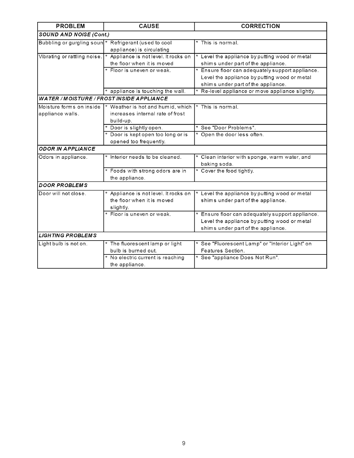
SOUND AND NOISE (Cont.)
Bubblingorgurglingsoun* Refrigerant(used to cool * This is normal.
appliance) is circulating
Vibrating or rattling noise. * Appliance is not level. It rocks on * Level the appliance by putting wood ormetal
the floor when it is moved shims under part of the appliance.
• Floor is uneven or weak. * Ensure floor can adequately support appliance.
Level the appliance by putting wood or metal
shims under part of the appliance.
• appliance is touching the wall. * Re-level appliance or move appliance slightly.
WATER/M OISTURE / FROST INSIDE A PPLIANCE
Moisture forms on inside *Weather is hotandhumid, which *This is normal.
appliance walls, increases internal rate of frost
build-up.
• Door is slightlyopen. * See "Door Problems".
• Dooris kept open too long or is * Open the doorless often.
opened too frequently.
ODOR IN APPLIANCE
Odors in appliance. * Interior needs to be cleaned. * Clean interior with sponge, warm water, and
baking soda.
• Foods with strong odors are in * Cover the food tightly.
the appliance.
DOOR PROBLEMS
Door will not close. * Appliance is not level. It rocks on * Level the appliance by putting wood ormetal
the floor when it is moved shims under part of the appliance.
slightly.
• Floor is uneven or weak. * Ensure floor can adequately support appliance.
Level the appliance by putting wood or metal
shims under part of the appliance.
LIGH TIN G PR OBLEM S
Light bulb is noton. * The fluorescentlamp orlight *See"FluorescentLamp"or"lnteriorLight"on
bulb is burned out. Features Section.
• No electric current is reaching * See "appliance Does NotRun".
the appliance.
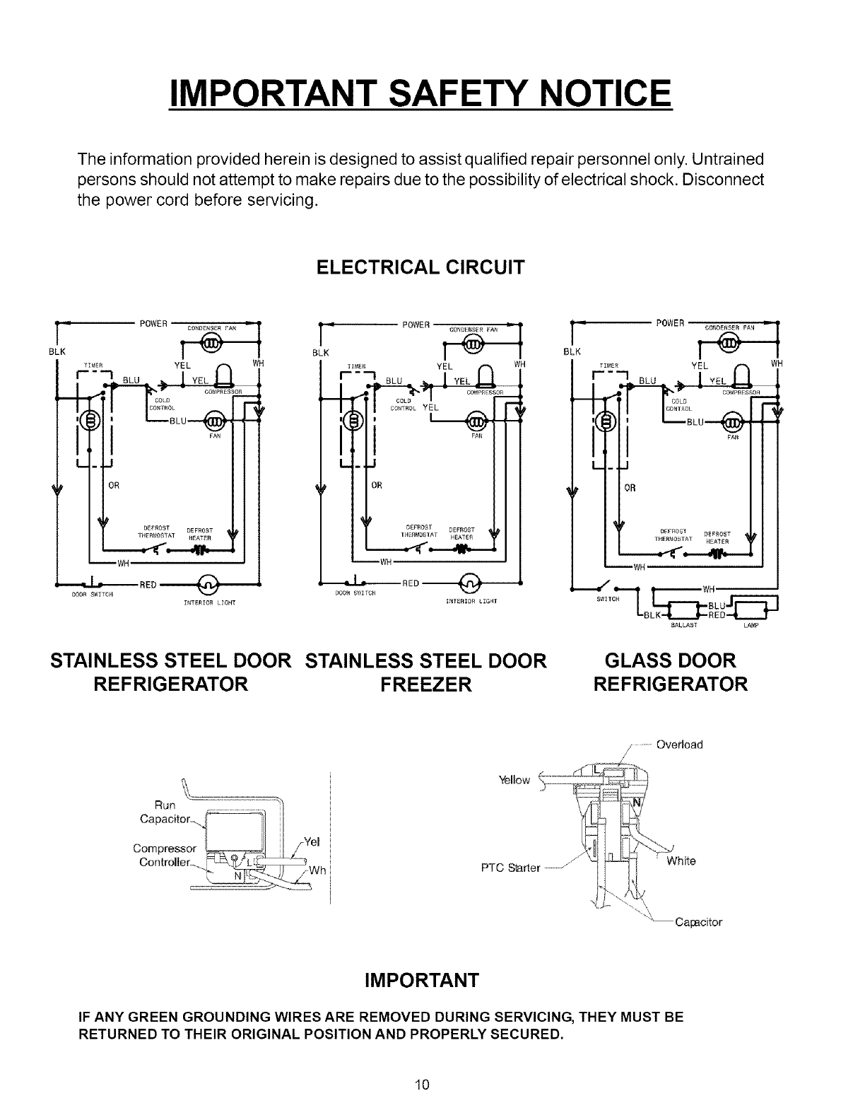
IMPORTANT SAFETY NOTICE
The information provided herein is designed to assist qualified repair personnel only. Untrained
persons should not attempt to make repairs due to the possibility of electrical shock. Disconnect
the power cord before servicing.
ELECTRICAL CIRCUIT
_ POWER -_
BLK
TI_E_ YEL f-_ WH
,_ _o_o--_-
I,I
L- J
OR
= POWER _ i = POWER
BLK BLK
YEL WH YEL WH
--WH 'WH
_RE0-----@---- -_- REO_--
Pooh _wlrc_ DOOR SgvIIOH
INTERIO£ L_GHT INTgRID_ LIG_IT
STAINLESS STEEL DOOR STAINLESS STEEL DOOR
REFRIGERATOR FREEZER
£ALLAST LA_p
GLASS DOOR
REFRIGERATOR
Run
Capacitor i
Compresso eJ
Controller__ Wh
i
Yellow
PTC S_arter --//
/.....Ovedoad
White
Catmcitor
IMPORTANT
IF ANY GREEN GROUNDING WIRES ARE REMOVED DURING SERVICING, THEY MUST BE
RETURNED TO THEIR ORIGINAL POSITION AND PROPERLY SECURED.
10
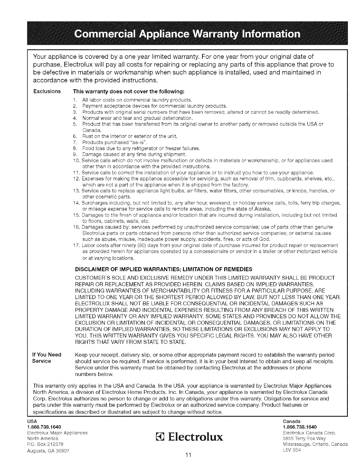
Your appliance is covered by a one year limited warranty. For one year from your original date of
purchase, Etectrolux will pay all costs for repairing or replacing any parts of this appliance that prove to
be defective in materials or workmanship when such appliance is installed, used and maintained in
accordance with the provided instructions.
Exclusions This warranty does not cover the following:
1. All labor costs on commercial laundry products.
2. Payment acceptance devices for commercial laundry products.
3. Products with original serial numbers that have been removed, altered or cannot be readily determined.
4. Normal wear and tear and gradual deterioration.
5. Product that has been transferred from its original owner to another party or removed outside the USA or
Canada.
6. Rust on the interior or exterior of the unit.
7. Products purchased "as-is".
8. Food loss due to any refrigerator or freezer failures.
9. Damage caused at any time during shipment.
10. Service calls which do not involve malfunction or defects in materials or workmanship, or for appliances used
other than Jn accordance with the provided instructions.
11. Service calls to correct the installation of your appliance or to instruct you how to use your appliance.
12. Expenses for making the appliance accessible for servicing, such as removal of trim, cupboards, shelves, etc.,
which are not a part of the appliance when it is shipped from the factory.
13. Service calls to replace appliance light bulbs, air filters, water filters, other consumables, or knobs, handles, or
other cosmetic parts.
14. Surcharges including, but not limited to, any after hour, weekend, or holiday service calls, tolls, ferry trip charges,
or mileage expense for service calls to remote areas, including the state of Alaska.
15. Damages to the finish of appliance and/or location that are incurred during installation, including but not limited
to floors, cabinets, wails, etc.
16. Damages caused by: services performed by unauthorized service companies; use of parts other than genuine
Electrolux parts or parts obtained from persons other than authorized service companies; or external causes
such as abuse, misuse, inadequate power supply, accidents, fires, or acts of God.
17. Labor costs after ninety (90) days from your original date of purchase incurred for product repair or replacement
as provided herein for appliances operated by a concessionaire or vendor in a trailer or other motorized vehicle
or at varying locations.
DISCLAIMER OF IMPLIED WARRANTIES; LIMITATION OF REMEDIES
CUSTOMER'S SOLE AND EXCLUSIVE REMEDY UNDER THIS LIMITED WARRANTY SHALL BE PRODUCT
REPAIR OR REPLACEMENT AS PROVIDED HEREIN. CLAIMS BASED ON IMPLIED WARRANTIES,
INCLUDING WARRANTIES OF MERCHANTABILITY OR FITNESS FOR A PARTICULAR PURPOSE, ARE
LIMITED TO ONE YEAR OR THE SHORTEST PERIOD ALLOWED BY LAW, BUT NOT LESS THAN ONE YEAR.
ELECTROLUX SHALL NOT BE LIABLE FOR CONSEQUENTIAL OR INCIDENTAL DAMAGES SUCH AS
PROPERTY DAMAGE AND INCIDENTAL EXPENSES RESULTING FROM ANY BREACH OF THIS WRITTEN
LIMITED WARRANTY OR ANY IMPLIED WARRANTY. SOME STATES AND PROVINCES DO NOT ALLOW THE
EXCLUSION OR LIMITATION OF INCIDENTAL OR CONSEQUENTIAL DAMAGES, OR LIMITATIONS ON THE
DURATION OF IMPLIED WARRANTIES, SO THESE LIMITATIONS OR EXCLUSIONS MAY NOT APPLY TO
YOU. THIS WRITTEN WARRANTY GIVES YOU SPECIFIC LEGAL RIGHTS. YOU MAY ALSO HAVE OTHER
RIGHTS THAT VARY FROM STATE TO STATE.
If You Need
Service Keep your receipt, delivery slip, or some other appropriate payment record to establish the warranty period
should service be required. If service is performed, it is in your best interest to obtain and keep all receipts.
Service under this warranty must be obtained by contacting Electrolux at the addresses or phone
numbers below.
This warranty only applies in the USA and Canada. tn the USA, your appliance is warranted by Electrolux Major Appliances
North America, a division of Electrolux Home Products, Inc. In Canada, your appliance is warranted by Electrolux Canada
Corp. Electrolux authorizes no person to change or add to any obligations under this warranty. Obligations for service and
parts under this warranty must be performed by Electrolux or an authorized service company. Product features or
specifications as described or illustrated are subject to change without notice.
USA
1.866.738.1640
Electrolux Major Appliances
North America
RO. Box 212378
Augusta, GA 30907
[] Electrolux
11
Canada
1.866.738.1640
Electrolux Canada Corp.
5855 Terry Fox Way
Mississauga, Ontario, Canada
L5V 3E4
