Frigidaire FGFL77ASC User Manual GAS RANGE Manuals And Guides L0207030
FRIGIDAIRE Free Standing, Gas Manual L0207030 FRIGIDAIRE Free Standing, Gas Owner's Manual, FRIGIDAIRE Free Standing, Gas installation guides
User Manual: Frigidaire FGFL77ASC FGFL77ASC FRIGIDAIRE GAS RANGE - Manuals and Guides View the owners manual for your FRIGIDAIRE GAS RANGE #FGFL77ASC. Home:Kitchen Appliance Parts:Frigidaire Parts:Frigidaire GAS RANGE Manual
Open the PDF directly: View PDF ![]() .
.
Page Count: 8
INSTALLATION AND SERVICE MUST BE PERFORMED BY A QUALIFIED INSTALLER.
IMPORTANT: SAVE FOR LOCAL ELECTRICAL INSPECTOR'S USE.
READ AND SAVE THESE INSTRUCTIONS FOR FUTURE REFERENCE.
If the information in this manual is not followed
exactly, a fire or explosion may result causing property
damage, personal injury or death.
FOR YOUR SAFETY:
-- Do not store or use gasoline or other flammable vapors
and liquids in the vicinity of this or any other appliance.
-- WHAT TO DO IF YOU SMELL GAS:
•Do not try to light any appliance.
•Do not touch any electrical switch; do not use any phone
in your building.
•Immediately call your gas supplier from a neighbor's
phone. Follow the gas supplier's instructions.
•If you cannot reach your gas supplier, call the fire
department.
-- Installation and service must be performed by a qualified
installer, service agency or the gas supplier.
•ALL RANGES
CANTIP
•INJURYTO PERSONS
COULD RESULT
•INSTALL ANTI-TIP
DEVICE PACKED WITH
RANGE
•SEE INSTALLATION
INSTRUCTIONS
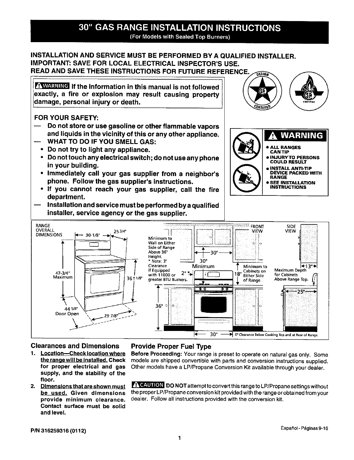
RANGE
OVERALL
DIMENSIONS 253/4"
RONT
i V EW
Minimum to _I i
Wall on Either _ ._J .. L_.:t _
Side of Range
Above 36" _30" --_)
Height. ___ I I
*Note: 3" I30" _
Clearance Minimum
with 1lOgO or 2" tl_ _;C_greater BTU Burners.
'I
36" _ o' J
J
SIDE
VIEW
Minimum to
,, _.aome_s on Maximum Depth
18 Either Side for Cabinets
_, of Above RangeTop, ;L
Range.
_!_/_i_ '_i' _i _! ii__
C_'Clearance Below Cooking Top and at Rear of Range.
Clearances and Dimensions Provide Proper Fuel Type
1. Location--Checklocationwhere Before Proceeding: Your range is preset to operate on natural gas only. Some
the ranae will be installed. Check models are shipped convertiblewith partsand conversioninstructionssupplied.
for proper electrical and gas Other models have a LP/Propane Conversion Kitavailable through your dealer.
supply, and the stability of the
floor.
2. Dimensionsthatareshownmu_t _l_T'_'_flr_lDONOTattempttoconvertthisrangetoLP/Propanesettingswithout
be used. Given dimensions theproperLP/Propaneconversionkitprovidedwiththerangeorobtainedfromyour
provide minimum clearance, dealer. Followall instructionsprovided withthe conversionkit.
Contact surface must be solid
and level.
EspaSol -Pdginas 9-16
P/N 316259316 (0112) 1
Important Notes to the Installer
1. Read all instructions contained in these installation
instructionsbefore installingrange.
2. Removeallpackingmaterialfromtheovencompartments
before connectingthe gas and electrical supply to the
range.
3. Observe all governing codes and ordinances.
4. Be sure to leave these instructions with the consumer.
Important Note to the Consumer
1. Keep these instructions with your owner's guide for
future reference.
IMPORTANT SAFETY
INSTRUCTIONS
Installation of this range must conform with local codes or, in
the absence of local codes, with the National Fuel Gas Code
ANSI Z223.1--1atest edition when installed in the United
States,
This range has been design certified by CSA International.
As with any appliance using gas and generating heat, there
are certain safety precautions you should fellow. You will find
them in the Use & Care Manual. read it carefully.
• Be sure your range is installed and grounded properly
by a qualified installer or service technician.
•This range must be electrically grounded in
accordance with local codes or, in their absence,
with the National Electrical Code ANSI/NFPA No .70_
latest edition when installed in the United States.
See Grounding Instructionson page 5.
Before installing the range in an area covered with
linoleum or any other synthetic floor covering, make
sure the floor covering can withstand heat at least
9O°F above room temperature without shrinking,
warping or discoloring. Do not installthe range over
carpetingunless youplace an insulatingpador sheet of
1/4-inchthickplywoodbetween the rangeandcarpeting.
•Make sure the wall coverings around the range can
withstand the heat generated by the range.
•Do not obstruct the flow of combustion air at the
oven vent nor around the base or beneath the lower
front panel of the range. Avoid touching the vent
openings or nearby surfaces as they may become hot
while the oven is in operation. This range requires fresh
air for proper burner combustion.
Never leave children alone or unattended
in the area where an appliance is in use, Aschildrengrow,
teach them the proper, safe use of all appliances. Never
leave the oven dooropen when the range is unattended.
Stepping, leaning or sitting on the doors
or drawers of this range canresult inserious injuries and
can also cause damage to the range.
Do not store items of interest to children in the
cabinets above the range. Childrencouldbe seriously
burned climbingonthe range to reach items.
To eliminate the need to reach over the surface
burners, cabinet storage space above the burners
should be avoided.
Adjust surface burner flame size so it does not
extend beyond the edge of the cooking utensil.
Excessive flame is hazardous.
Do not use the oven as a storage space. This creates
a potentially hazardoussituation.
Never use your range for warming or beating the
room. Prolonged use of the range without adequate
ventilation can be dangerous.
Do not store or use gasoline or other flammable
vapors and liquids near this or any other appliance.
Explosionsor fires could result.
Reset all controls to the "off" position after using a
programmable timing operation.
FOR MODELS WITH SELF-CLEAN FEATURE:
•Remove broiler pan, food and other utensils before
self-cleaning the oven. Wipe upexcessspillage. Follow
the precleaning instructionsin the Owner's Guide.
Unlike the standard gas range, THIS COOKTOP IS
NOT REMOVABLE. Do not attempt to remove the
cooktop.
DO NOT MAKE ANY ATTEMPT TO
OPERATE THE ELECTRIC IGNITION OVEN DURING AN
ELECTRICAL POWER FAILURE. RESET ALL OVEN
CONTROLS TO "OFF" IN THE EVENT OF A POWER
FAILURE.
The electric ignitor will automatically re-ignite the oven
burner when power resumes if the oven thermostat contr,
was left in the "ON" position.
When an electrical power failure occurs during use, the
surface burners will continue to operate.
During a power outage, the surface burners can be lit with
a match. Hold a lighted match to the burner, then slowly turn
the knob to the LITE position. Use extreme caution when
lighting burners this way.
2
Before Starting
Tools You Will Need
For leveling legs and Anti-Tip Bracket:
Adjustable wrench or channel lock pliers
5/16" Nutdriver or Flat Head Screw Driver _{]==_=
•Electric Drill & 1/8" Diameter Drill Bit (5/32" Masonry Drill
Bit if installing in concrete)
For gas supply connection:
•Pipe wrench
For burner flame adjustment:
Phillipshead _ and
blade-typescrewdrivers
For gas conversion (LP/Propane or Natural):
• Open end wrench - 1/2"
Additional Materials You Will Need
Gas line shut-oft valve
Pipe joint sealant that resists action of LP/Propane gas
A new flexible metal appliance conduit (1/2" NPT x 3/4"
or 1/2" I.D.) must be design certified by CSA International.
Because solid pipe restricts moving the range we
recommend using a new flexible conduit (4 to 5 foot
length) for each new installation and additional
reinstallations.
• Always use the (2) new flare union adapters (1/2" NPT x
3/4" or 1/2" I.D.) supplied with the new flexible appliance
conduit for connection of the range.
Normal Installation Steps
1. Anti-Tip Bracket Installation Instructions
Important Safety Warning
To reduce the riskof tipping of the range, the range must be
secured to the floorby properly installedanti-tip bracket and
screws packed withthe range. Failure to installthe anti-tip
bracket will allowthe range to tipover if excessive weight is
placed on an open door or if achildclimbs upon it. Serious
injury might resultfrom spilled hot liquidsor from the range
itself.
If range is ever moved to a different location, the anti-tip
brackets must also be moved and installed with the range.
Instructions are provided for installation in wood or cement
fastened to either the floor or wall. When installed to the wall,
make su rethat screws completely penetrate dry wall and are
secu red inwood or metal. When fastening to the floor orwall,
be sure that screws do not penetrate electrical wiring or
plumbing.
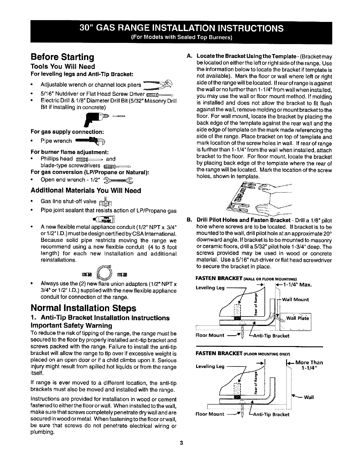
A.
a.
3
Locate the Bracket Using the Template- (Bracket may
be locatedoneitherthe left orrightsideofthe range. Use
the informationbelow to locatethe bracketiftemplate is
not available). Mark the flooror wall where left or right
sideofthe rangewillbe located, Ifrearof rangeisagainst
thewallornofurtherthan 1-1/4"fromwallwhen installed,
you may use the wall orfloor mount method, If molding
is installed and does not allow the bracket to fit flush
against the wall, remove molding ormountbrackettothe
floor. For wall mount, locate the bracket by p!acing the
back edge of the template againstthe rearwall and the
side edge of template on the mark made referencing the
side of the range. Place bracket on top of template and
mark location of the screw holes in wall. If rear of range
is further than 1-1/4" from the wall when installed, attach
bracket to the floor. For floor mount, locate the bracket
by placing back edge of the template where the rear of
the range will be located. Mark the location of the screw
holes, shown in template.
Drill Pilot Holes and Fasten Bracket - Drill a 1/8" pilot
hole where screws are to be located. If bracket is to be
mounted to the wall, drill pilot hole at an approximate 20°
downward angle. If bracket is to be mounted to masonry
or ceramic floors, drill a 5/32" pilot hole 1-3/4" deep. The
screws provided may be used in wood or concrete
material. Use a 5/16" nut-driver or flat head screwdriver
to secure the bracket in place.
FASTEN BRACKET (WALL OR FLOOR MOUNTING)
--_1 !<--1-1/4" Max.
Leveling Leg --
t
Wall Plate
Floor Mount Jp Bracket
FASTENBRACKET(FLOOnMOUNTINGONLY}
Leveling an
1-1/4 °,
Floor Mount Jii p Bracket
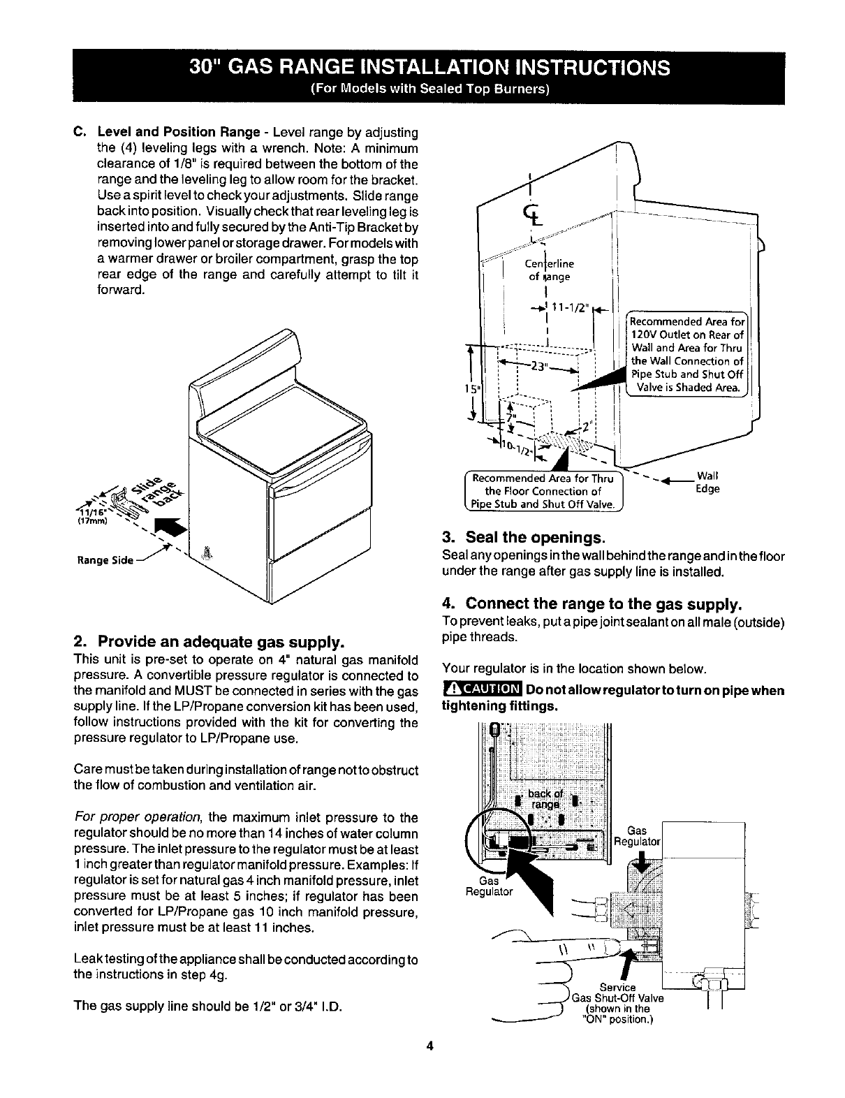
C. Level and Position Range - Level range by adjusting
the (4) leveling legs with a wrench. Note: A minimum
clearance of 1/8" is requiredbetween the bottom of the
range and the leveling legto allow roomfor the bracket.
Use aspiritlevel to checkyouradjustments. Slide range
back intoposition. Visuallycheck that rear levelingleg is
insertedintoand fully secured bythe Anti-TipBracketby
removing lowerpanel orstorage drawer. Formodelswith
a warmer drawer or broiler compartment, grasp the top
rear edge of the range and carefully attempt to tilt it
forward.
(17ram)
Range Side _"
2. Provide an adequate gas supply.
This unit is pre-set to operate on 4" natural gas manifold
pressure. Aconvertible pressure regulator is connected to
the manifold and MUST be connected in series with the gas
supply line. If the LP/Propane conversion kit has been used,
follow instructions provided with the kit for converting the
pressure regulator to LP/Propane use.
Care must be taken during installationof range nottoobstruct
the flow of combustion and ventilation air.
For proper operation, the maximum inlet pressure to the
regulator should be no more than 14 inches of water column
pressure. The inlet pressure to the regulator must be at least
1 inch greater than regulator manifold pressure. Examples: If
regulator is set for natural gas 4 inch manifold pressure, inlet
pressure must be at least 5 inches; if regulator has been
converted for LP/Propane gas 10 inch manifold pressure,
inlet pressure must be at least 11 inches.
Leak testing of the appliance shall be conducted according to
the instructions in step 4g.
The gas supply line should be 1/2" or 3/4" I.D.
ige
I
--_111-1/2 ___
r"Recommended Area for]l
I / 120V Outlet on Rear ell!
I ._,.=: ÷-----I ...... ,|WallandAreaforThru|
......:?i theWo,,Conno ,,ooo,,
i " "'* ---_ 3_ PipeStubandShutOff|l
. i i._ P , ValveisShadedArea'JI
-J_7" i _ ', ,,:
__ .._.,_ ,, I J
I,..o en0e0,o.,o,, u] ,--W"
the Floor Connection of Edge
Pipe Stub and Shut Off Valve.
3. Seal the openings.
Seal any openingsinthe wallbehindthe rangeandinthe floor
underthe range after gas supplyline is installed.
4. Connect the range to the gas supply.
To prevent leaks, put a pipejoint sealant on allmale (outside)
pipe threads.
Your regulator is in the location shown below.
Do not allow regulator to turn on pipe when
tightening fittings.
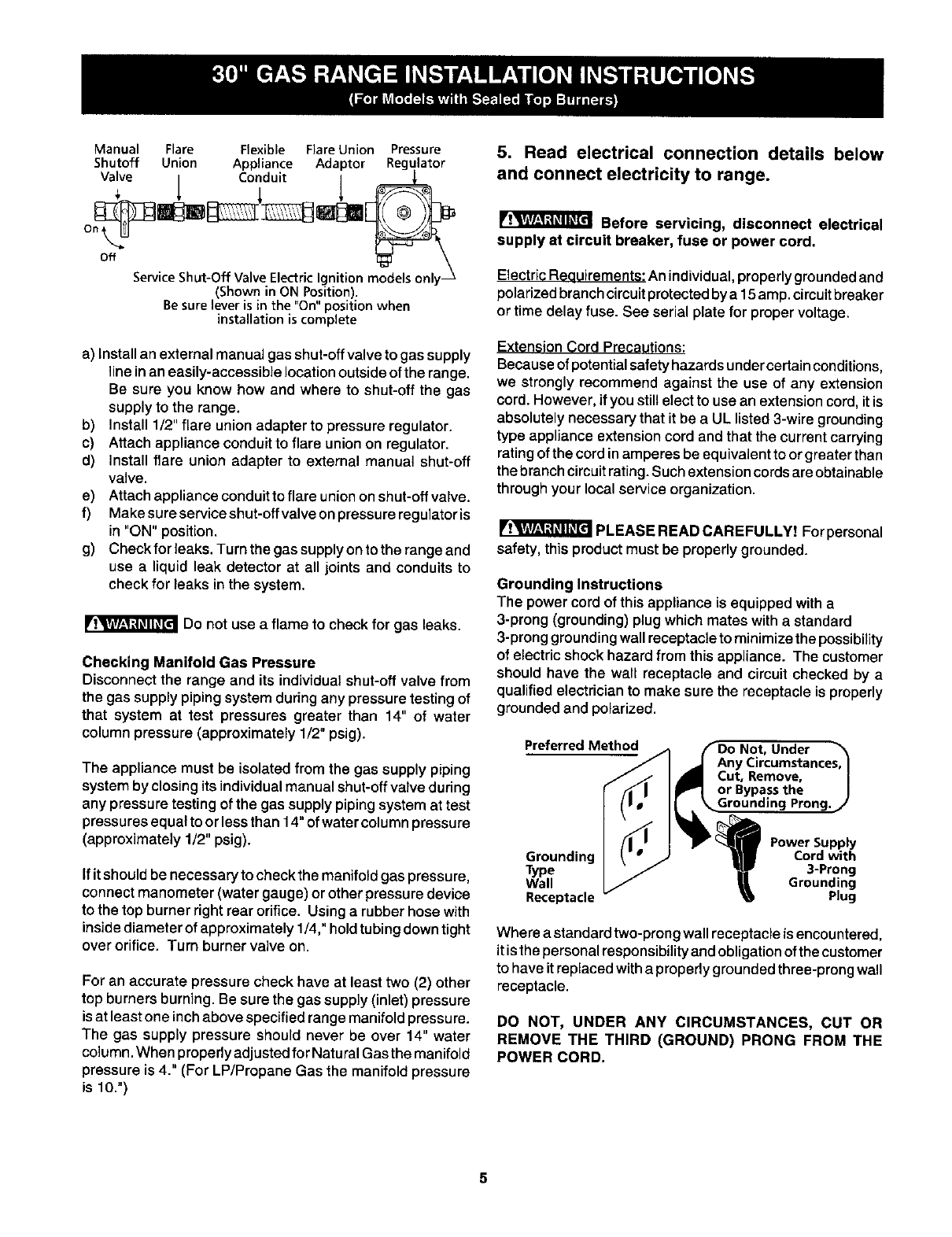
Manual Flare Flexible Flare Union Pressure
Shutoff Union Appliance Adaptor Regulator
Valve 1 Co:duit 1 _
ServiceShut-Off ValveElectricIgnitionmodelsonly
(Shown in ON Position).
Besure leveris in the "On"position when
installation is complete
a) Installan external manual gas shut-off valve to gas supply
line in an easily-accessible location outside of the range.
Be sure you know how and where to shut-off the gas
supply to the range.
b) Install 1/2" flare union adapter to pressure regulator.
c) Attach appliance conduit to flare union on regulator.
d) Install flare union adapter to external manual shut-off
valve.
e) Attach appliance conduit to flare union on shut-off valve.
f) Make sure service shut-offvalve on pressure regulator is
in "ON" position.
g) Check for leaks. Turn the gas supply on to the range and
use a liquid leak detector at all joints and conduits to
check for leaks in the system.
Do not use a flame to check for gas leaks.
Checking Manifold Gas Pressure
Disconnect the range and its individual shut-off valve from
the gas supply piping system during any pressure testing of
that system at test pressures greater than 14" of water
column pressure (approximately 1/2" psig).
The appliance must be isolated from the gas supply piping
system by closing its individual manual shut-off valve during
any pressure testing of the gas supply piping system at test
pressures equal to or less than 14" of water colu mn pressure
(approximately 1/2" psig).
If it should be necessary to check the manifold gas pressure,
connect manometer (water gauge) or other pressure device
to the top burner right rear orifice. Using a rubber hose with
inside diameter of approximately 1/4," hold tubing down tight
over orifice. Turn burner valve on.
For an accurate pressure check have at least two (2) other
top burners burning. Be sure the gas supply (inlet) pressure
is at least one inch above specified range manifold pressu re.
The gas supply pressure should never be over 14" water
column. When properly adjusted for Natural Gas the manifold
pressure is 4." (For LP/Propane Gas the manifold pressure
is 10.")
5. Read electrical connection details below
and connect electricity to range.
Before servicing, disconnect electrical
supply at circuit breaker, fuse or power cord,
Electric Requirements: An individual, properly grounded and
polarized branch circuit protected by a 15amp. circuit breaker
or time delay fuse. See serial plate for proper voltage.
ExtensionCord Precautions:
Because of potential safety hazards undercertain conditions,
we strongly recommend against the use of any extension
cord. However, if you still elect to use an extension cord, it is
absolutely necessary that it be a UL listed 3-wire grounding
type appliance extension cord and that the current carrying
rating of the cord in amperes be equivalent to or greater than
the branch circuit rating. Such extension cords are obtainable
through your local service organization.
PLEASE READ CAREFULLY! For personal
safety, this product must be properly grounded.
Grounding Instructions
The power cord of this appliance is equipped witha
3-prong (grounding)plugwhich mates witha standard
3-pronggroundingwallreceptacleto minimizethe possibility
of electricshockhazard from thisappliance. The customer
should have the wall receptacle and circuitchecked by a
qualifiedelectricianto make sure the receptacle is properly
groundedand polarized.
Preferred Method /'1 f_Do Not, Under
/I _1 AnyCircumstances,I
//. I_Cut, Remove, /
r _ I I_°r Bypassthe /
Grounding I _" • -I/ _ Cord with
Type I "/ _lW 3-Prong
Wall I /B, Grounding
Receptacle _ _ Plug
Where a standard two-prong wall receptacle is encountered,
it is the personal responsibility and obligation of the customer
to have it replaced with a properly grounded three-prong wall
receptacle.
DO NOT, UNDER ANY CIRCUMSTANCES, CUT OR
REMOVE THE THIRD (GROUND) PRONG FROM THE
POWER CORD.
5
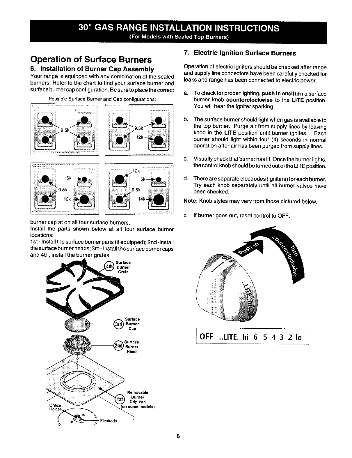
Operation of Surface Burners
6. Installation of Burner Cap Assembly
Your range is equippedwith any combinationof the sealed
burners. Refer to the chart to find your surface burner and
surfaceburnercap configuration.Besureto placethecorrect
PossibleSurfaceBurnerand Cap configurations:
............... i ......
9 5k 9 5k
.........
burner cap at on all four surface burners.
Install the parts shown below at all four surface burner
locations:
I st - Install the surface burner pans (if equipped); 2nd -install
the surface burner heads; 3rd- install the surface burner caps
and 4th; install the burner grates.
Surface
Burner
Grate
Sudace
Cap
Su_ece
Burner
Head
7. Electric Ignition Surface Burners
Operation of electric ignitersshould be checked after range
and supply line connectorshave been carefully checked for
leaks and range has been connected to electric power.
a. To check for proper lighting, push in and turn a surface
burner knob counterclockwise to the LifE position.
You will hear the ignitersparking.
b, The surface burner should light when gas is available to
the top burner. Purge air from supply lines by leaving
knob in the LITE position until burner ignites, Each
burner should light within four (4) seconds in normal
operation after air has been purged from supplylines.
c. Visually check that burner has lit. Once the burner lights,
the control knob should be turned out of the LITE position.
d. There are separate electrodes (igniters) for each burner.
Try each knob separately until all burner valves have
been checked.
Note: Knob styles may vary fromthose pictured below.
c. If burner goes out, reset control to OFF.
OFF ..UTE..hi 65432Io
Removable
Burrter
Drip Pan
OriflC_Holder Electrode_S°me_ models)
6
8. Adjust the "LOW" Setting of Surface Burner
Valve (Linear Flow Valves Only):
TO
Surface
Burner
Test to verify if "LOW" setting should be adjusted
a. Push in and turn control to LITE until burner ignites.
b. Push in and auickly turn knob to LOWEST POSITION.
d. Remove the surface burner control knob.
e. Insert a thin-bladed screwdriver into the hollow valve
stem and engage the slotted screw inside. Flame size
can be increased or decreased with the turn of the screw.
Turn counterclockwise to increase flame size. Turn
clockwise to decrease flame size.
After removing all packing materials and literature from the
oven:
a) Set oven to BAKE at 300-°F, See Use & Care Manual for
operating instructions,
b) Within 60 seconds the oven burner should ignite. Check
for proper flame, and allow the burner to cycle once.
Reset controls to off.
c) If your model is equipped with awaist-high broiler, set
oven to BROIL. See a_ for operating
instructions.
d) Within 60 seconds the broil burner should ignite. Check
for proper flame. Reset controls to off.
10. Air Shutter-Oven Burner
Waist-High Burner
(SelfClean Models)
Adjust flame until you can quickly turn knob from LITE to
LOWEST POSITION without extinguishing the flame. Flame
should be as small as possible without going out.
Note: Air mixture adjustment is not required on surface
burners.
Operation of Oven Burners and
Oven Adjustments
9. Electric Ignition Burners
Operation of electric igniters should be checked after range
and supply line connectors have been carefully checked for
leaks and range has been connected to electric power.
The oven burner is equipped with an electric control system
as well as an electric oven burner igniter. If your model is
equipped with a waist-high broil burner, it will also have an
electric burner igniter. These control systems require no
adjustment. When the oven is set to operate, current will flow
to the igniter. It will "glow" similar to a light bulb. When the
igniter has reached a temperature sufficient to ignite gas, the
electrically controlled oven valve will open and flame will
appear at the oven burner. There is a time lapse from 30 to
60 seconds after the thermostat is turned ON before the
flame appears at the oven burner. When the oven reaches
the dial setting, the glowing igniter will go off. The burner
flame will go "out" in 20 to 30 seconds after the igniter goes
"OFF." To maintain any given oven temperature, this cycle
will continue as long as the dial (or display) is set to operate.
The approximate flame lengthof the oven burner is 1inch
(distinct inner, blue flame).
To determine if the oven burner flame is proper, remove the
oven bottom and burner baffle and set the oven to bake at
300°F.
To remove the oven bottom, remove oven hold down screws
at rear of oven bottom. Pull upat rear, disengage front of oven
bottom from oven front frame, and pull the oven bottom out
of the oven. Remove burner baffle so that the burner flame
can be observed.
If the flame is yellow in color, increase air shutter opening
size. (See "2" in illustration below.) If the flame is a distinct
blue, reduce the air shutter opening size.
To adjust loosen lock screw (see "3" illustration below),
reposition air shutter, and tighten lock screw. Replace oven
bottom.
(_ Lock Screw
(_Air Shutter
Oven
Tube
®
Orifice
Hood
11. Air Shutter-Broil Burner
The approximate flame length of the broil burner is 1 inch
(distinctinner, blue flame).
To determine if the broil burner flame is proper, set the oven
to broil.
If the flame is yellow in color, increase air shutter opening
size. (See "2" in illustration above.) If the flame is a distinct
blue, reduce the air shutter opening size.
To adjust, loosen lock screw (see "3" in illustration above),
reposition air shutter, and tighten lock screw.
12.Make Sure Range is Level.
Level the range by placing a level horizontally on an oven
rack. Check diagonally from front to back, then level the
range by either adjusting the leveling legs or by placing shims
under the corners of the range as needed.
13.After installation is complete, make sure all
controls are left in the OFF position.
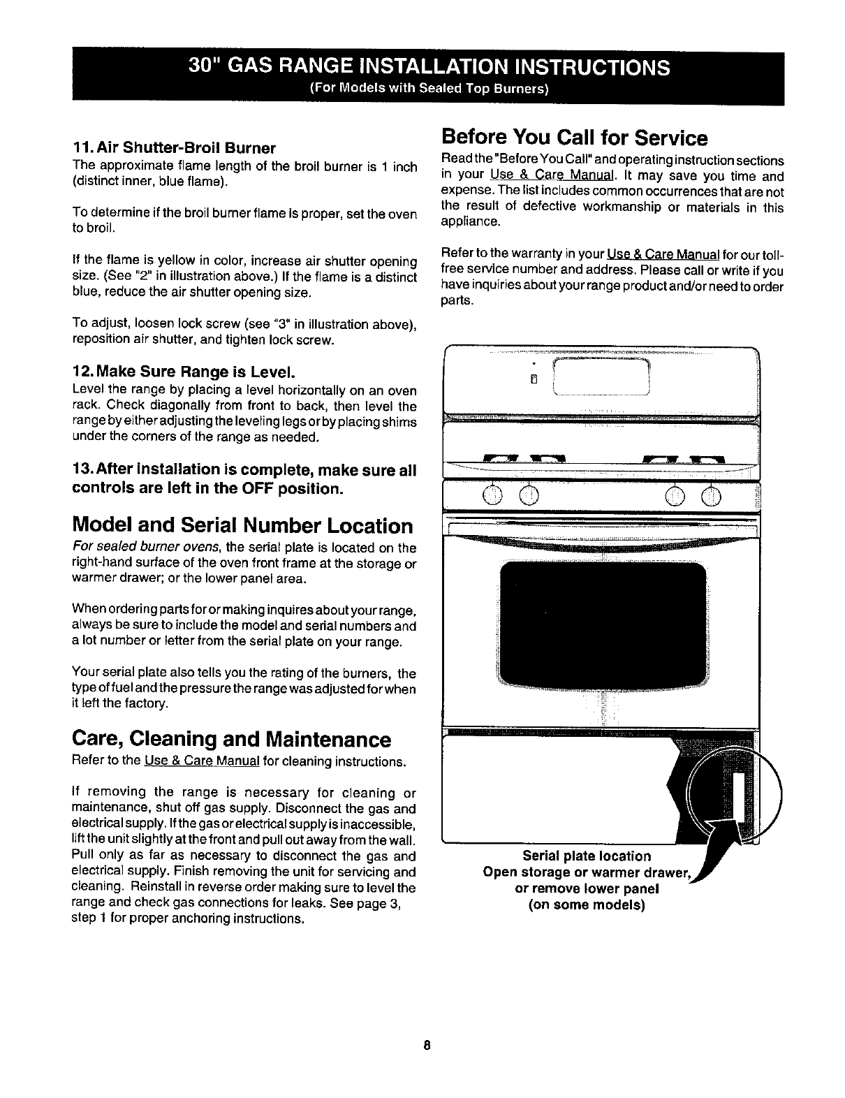
Model and Serial Number Location
For sealed burner ovens, the serial plate is located on the
right-hand surface of the oven front frame at the storage or
warmer drawer; or the lower panel area.
When ordering parts foror making inquires about your range,
always be sure to include the model and serial numbers and
a lot number or letter from the serial plate on your range.
Your serial plate also tells you the rating of the burners, the
type of fuel and the pressure the range was adjusted for when
it left the factory.
Care, Cleaning and Maintenance
Refer to the Use & Care Manual forcleaning instructions.
if removing the range is necessary for cleaning or
maintenance, shut off gas supply. Disconnect the gas and
electrical supply. Ifthe gas or electrical supply is inaccessible,
lift the unit slightly at the front and pull out away from the wall.
Pull only as far as necessary to disconnect the gas and
electrical supply. Finish removing the unit for servicing and
cleaning. Reinstall in reverse order making sure to level the
range and check gas connections for leaks. See page 3,
step 1 for proper anchoring instructions.
Before You Call for Service
Read the "Before You Call" and operating instruction sections
in your Use & Care Manual. It may save you time and
expense. The listincludes common occurrences that are not
the result of defective workmanship or materials in this
appliance.
Refer to the warranty inyour a_ for our toll-
free service number and address. Please call or write if you
have inquiries about your range product and/or need to order
parts.
......................... J
©© ...... ©©
iill
Serial plate location
Open storage or warmer drawer
or remove lower panel
(on some models)
