Frigidaire GLTF2940EE0 User Manual WASHER Manuals And Guides L0710022
FRIGIDAIRE Residential Washers Manual L0710022 FRIGIDAIRE Residential Washers Owner's Manual, FRIGIDAIRE Residential Washers installation guides
User Manual: Frigidaire GLTF2940EE0 GLTF2940EE0 FRIGIDAIRE WASHER - Manuals and Guides View the owners manual for your FRIGIDAIRE WASHER #GLTF2940EE0. Home:Laundry & Garment Care Parts:Frigidaire Parts:Frigidaire WASHER Manual
Open the PDF directly: View PDF ![]() .
.
Page Count: 6
installation
instructions
Ful! Size Tumble Action Washers
Before beginning installation, carefully read these instructions. This will simpfify the
installation and ensure the washer is installed correctly and safely. Leave these instructions
near the washer after installation for future reference.
NOTE: The electrical service to the washer must conform with local codes and ordinances
and the latest edition of the National Electrical Code, ANS!/NFPA 70.
For your safety the information in
this manual must be followed to minimize the risk
of fire or explosion or to prevent property damage,
personal injury or loss of life.
- Do not store or use gasoline or other flammable
vapors and liquid in the vicinity of this or any
other appliance.
-WHAT TO DO IF YOU SMELL GAS
•Do not try to light any appliance.
•Do not touch any electrical switch; do not
use any phone in your building.
•Clear the room, building or area of all
occupants.
•Immediately call your gas supplier from a
neighbor's phone. Follow the gas suppliers
instructions.
•If you cannot reach your gas supplier, call
the fire department.
Installation and service must be performed by a
qualified installer, service agency or the gas
supplier.
Printed in U.S.A.
Contents
SUBJECT PAGE
Pre-lnstallation Requirements 2
Electrical Requirements 2
Grounding Requirements 2
Water Supply Requirements 2
Drain Requirements 2
Rough-In Dimensions 3
Location Of Your Washer 4
Unpacking 4
Installation 5-6
Replacement Parts 6
WN 134762900(0605)
PRE-INSTALLAT!ON REQUIREMENTS
Tools Required for Installation:
I. Phillips screwdriver
2. 10 mm socketwith ratchet.
3. Channel-lock adjustable pliers.
4. Carpenter's level.
absence of local codes, with the National Electrical
Codes, ANSI/NFPA 70 (latest edition). If in doubt,
call a licensed electrician. DO NOTcut off or alter
the grounding prong on the power supply cord. In
situations where a two-slot receptacle is present,
it is the owner's responsibility to have a licensed
electrician replace it with a properly grounded
three prong grounding type receptacle.
ELECTRICAL REQUIREMENTS
CIRCUIT- Individual, properly polarized and grounded
15 amp. branch circuit fused with 15 amp. time delay
fuse or circuit breaker.
POWER SUPPLY- 2 wire, with ground, 120 volt, single
phase, 60 Hz, Alternating Current. NOTE: Because of
potential inconsistent voltage capabilities, the use of this
washer with power created by gas powered generators,
solar powered generators, wind powered generators or
any other generator other than the local utility company
is not recommended.
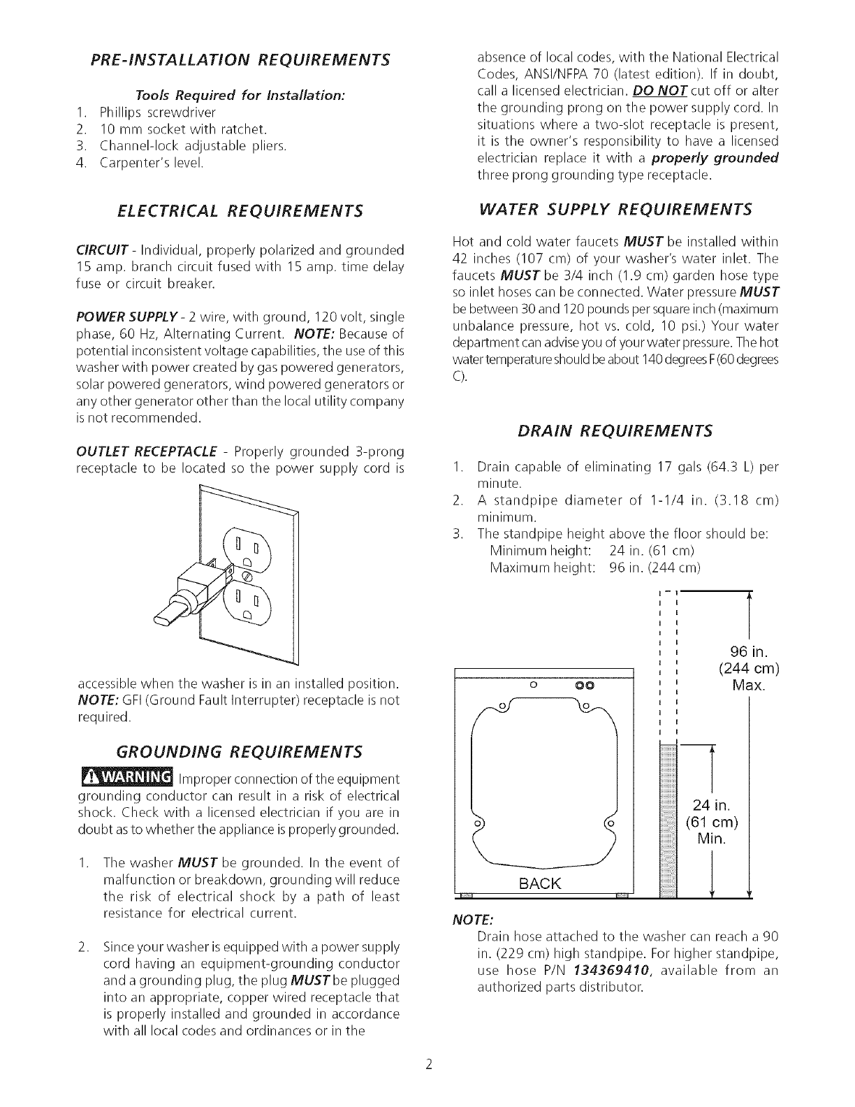
OUTLET RECEPTACLE - Properly grounded 3-prong
receptacle to be located so the power supply cord is
accessible when the washer is in an installed position.
NOTE: GFI (Ground Fault Interrupter) receptacle is not
required.
GROUNDING REQUIREMENTS
Improper connection of the equipment
grounding conductor can result in a risk of electrical
shock. Check with a licensed electrician if you are in
doubt asto whether the appliance isproperly grounded.
.The washer MUST be grounded. In the event of
malfunction or breakdown, grounding will reduce
the risk of electrical shock by a path of least
resistance for electrical current.
.Since your washer is equipped with a power supply
cord having an equipment-grounding conductor
and a grounding plug, the plug MUSTbe plugged
into an appropriate, copper wired receptacle that
is properly installed and grounded in accordance
with all local codes and ordinances or in the
WATER SUPPLY REQUIREMENTS
Hot and cold water faucets MUST be installed within
42 inches (107 cm) of your washer's water inlet. The
faucets MUST be 3/4 inch (1.9 cm) garden hose type
so inlet hoses can be connected. Water pressure MUST
be between 30 and 120 pounds per squareinch (maximum
unbalance pressure, hot vs. cold, 10 psi.) Your water
department can adviseyou of your water pressure.The hot
water temperatureshouldbeabout 140degreesF(60 degrees
C).
DRAIN REQUIREMENTS
I. Drain capable of eliminating 17 gals (64.3 L) per
minute.
2. A standpipe diameter of 1-1/4 in. (3.18 cm)
minimum.
3. The standpipe height above the floor should be:
Minimum height: 24 in. (61 cm)
Maximum height: 96 in. (244cm)
BACK
II
r
96 in.
(244 cm)
Max.
iiiiiiiiii
iiiiiiiiii
..........24 in.
(61 cm)
_ MJn.
!!!!!!!!!!i 1
NOTE:
Drain hose attached to the washer can reach a 90
in. (229 cm) high standpipe. For higher standpipe,
use hose P/N 134359410, available from an
authorized parts distributor.
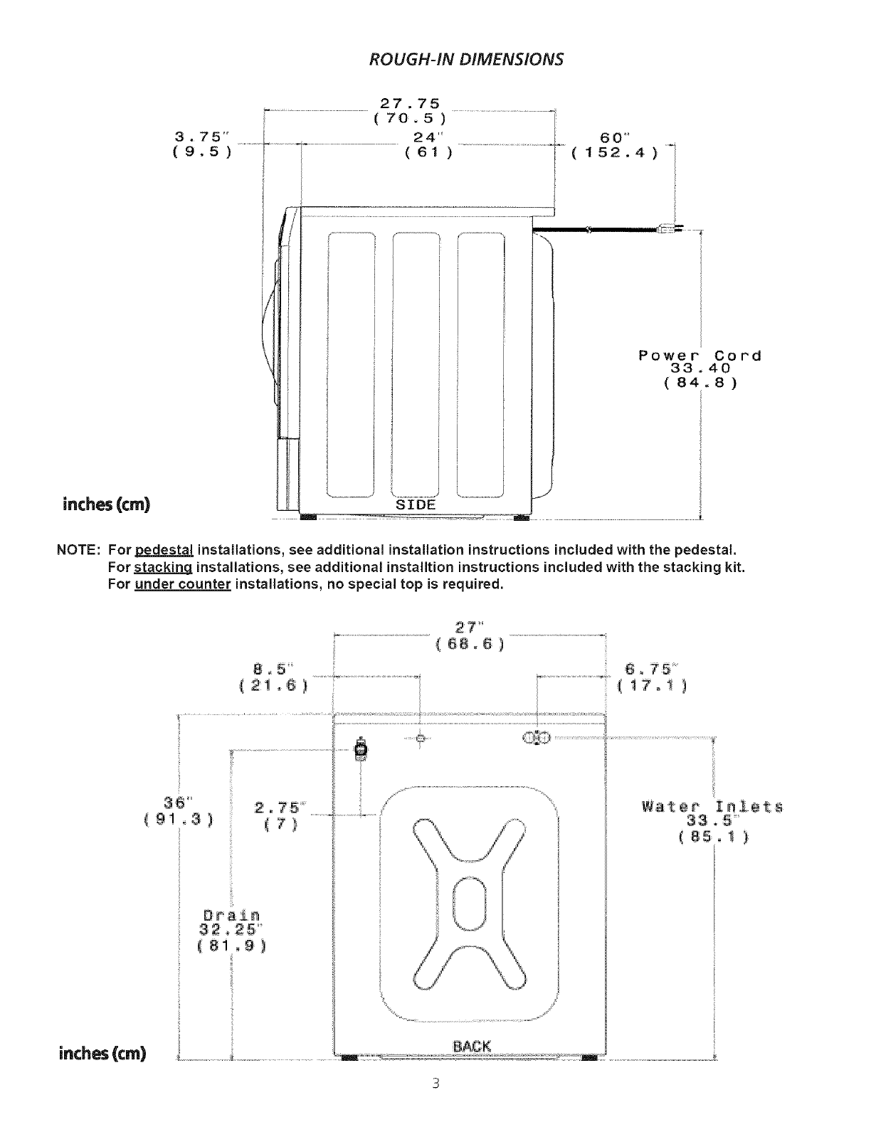
ROUGH-IN DIMENSIONS
inches(cm)
Power" Cord
33 .40
(84 8)
NOTE: For pedestal installations, see additional installation instructions included with the pedestal.
For stacking installations, see additional installtion instructions included with the stacking kit.
For under counter installations, no special top is required.
9 ! 3 )
inches (cm)
8 ° 5'
................................._- i_¸
{18.8)
L_iO.....................................;
ware# Z a ! e t s
33,5
=(85, _ )
LOCATION OF YOUR WASHER
DO NOTINSTALL YOUR WASHER:
1. In an area exposed to dripping water or outside weather 4.
conditions. The ambient temperature should never be below
60 ° F (15.6 ° C) for proper washer (detergent breakdown) 5.
operation.
2. In an area where it will come in contact with curtains or
drapes. 6.
3. In an area (garage or garage-type building) where gasoline
of other flammables are kept or stored (including
automobiles).
4. On carpet. Floor MUST be solid with a maximum slope of
1/2 in. per foot (I .27 cm per 30.5 cm). To ensure vibration 7.
or movement does not occur, reinforcement of the floor
may be necessary.
IMPORTANT
MINIMUM INSTALLATION CLEARANCES
When installed in alcove or closet:
Sides, Rear = 0 in. (0 cm)
Top = 0 in. (0 cm)
When installed in closet: Front = I in. (2.54 cm)
Closet door ventilation required: 2 Iouvered openings each 60
in2(387 cm2), 3 in. (7.6 cm) from top and bottom of door.
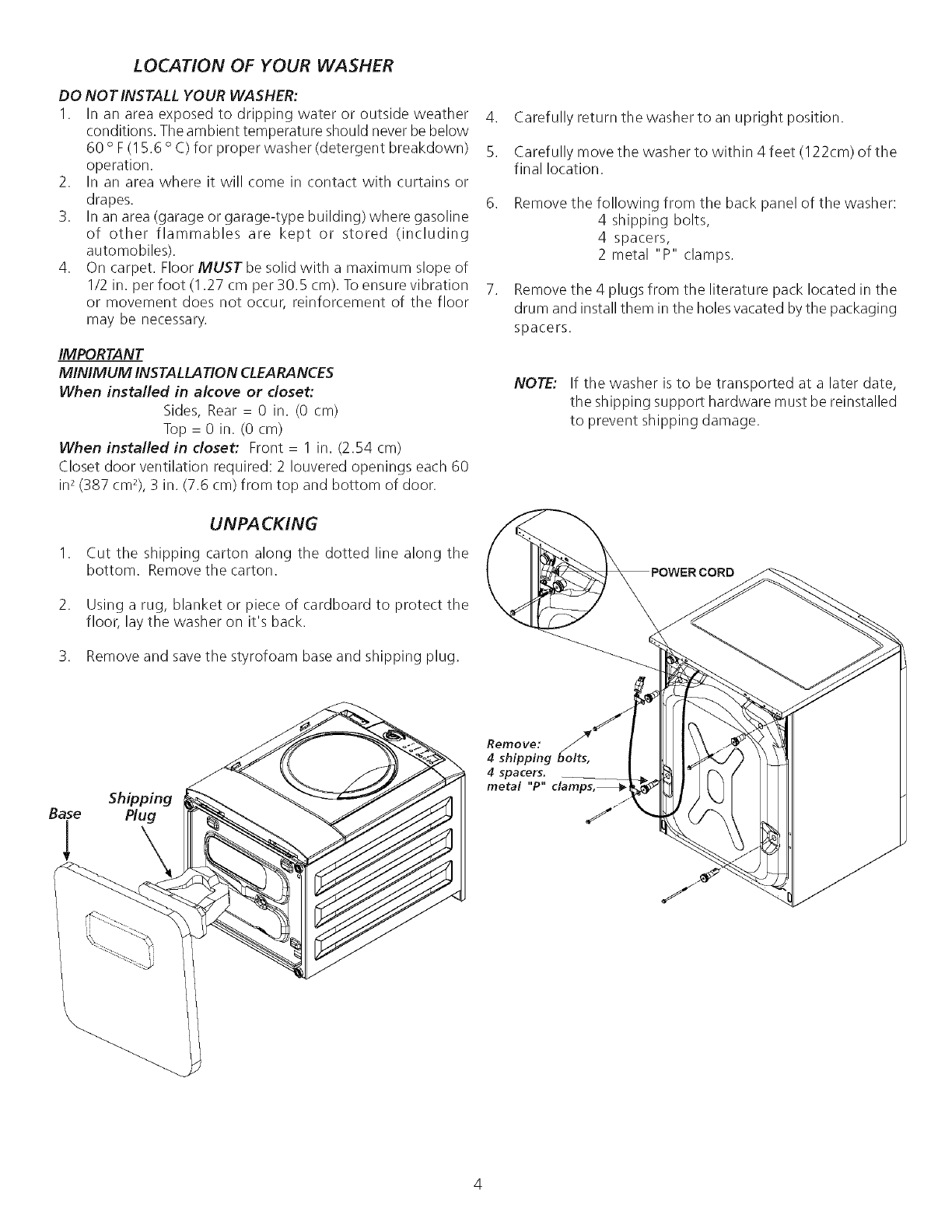
UNPACKING
1. Cut the shipping carton along the dotted line along the
bottom. Remove the carton.
2. Using a rug, blanket or piece of cardboard to protect the
floor, lay the washer on it's back.
3. Remove and savethe styrofoam base and shipping plug.
Shoping
Base Plug
Carefully return the washer to an upright position.
Carefully move the washer to within 4 feet (122cm) of the
final location.
Remove the following from the back panel of the washer:
4 shipping bolts,
4 spacers,
2 metal "P" clamps.
Remove the 4 plugs from the literature pack located in the
drum and install them in the holes vacated by the packaging
spacers.
NOTE: If the washer is to be transported at a later date,
the shipping support hardware must be reinstalled
to prevent shipping damage.
Remove:
4 shipping _olts,
4 spacers.
metal "P"
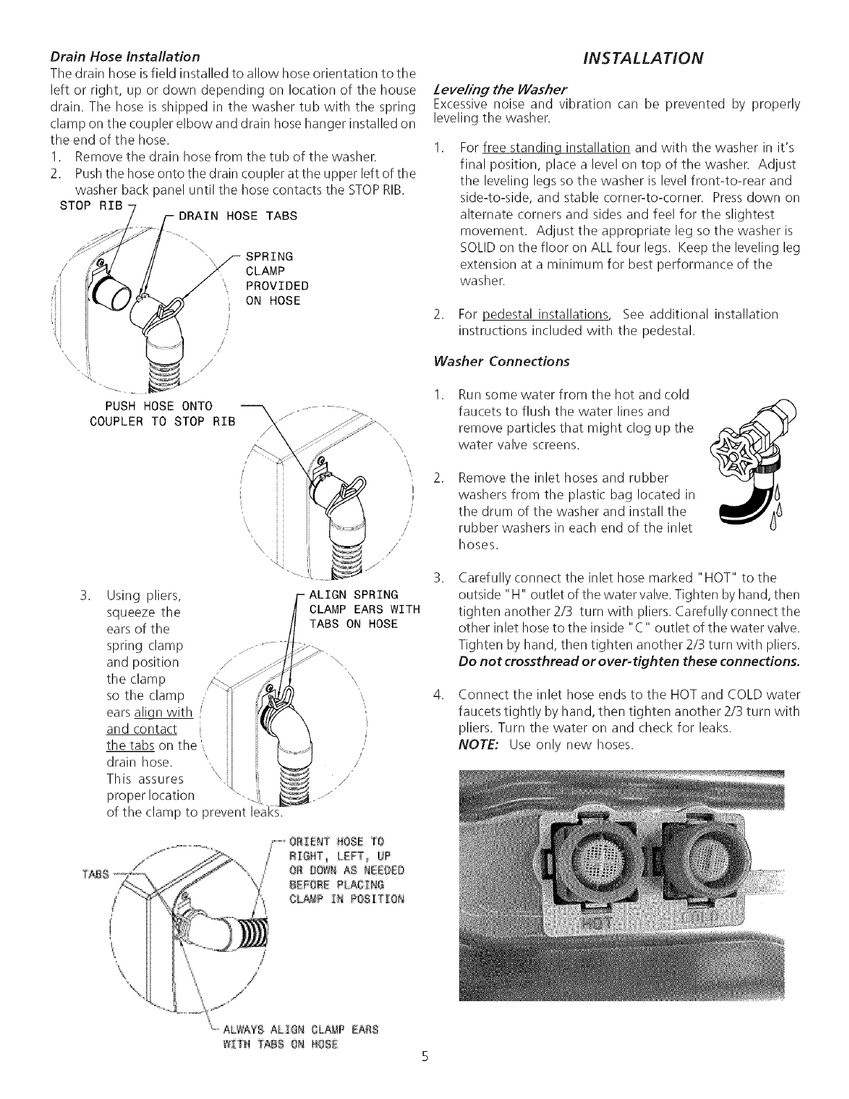
Drain Hose Installation
The drain hose isfield installed to allow hose orientation to the
left or right, up or down depending on location of the house
drain. The hose is shipped in the washer tub with the spring
clamp on the coupler elbow and drain hose hanger installed on
the end of the hose.
1. Remove the drain hose from the tub of the washer.
2. Push the hoseonto the drain coupler at the upper left of the
washer back panel until the hose contacts the STOPRIB.
x_ SPRING
CLAMP
PROVIDED
ON HOSE
i
/
PUSH HOSE ONTO .........
COUPLER TO STOP RIB _zl
,\ ' i
\\\
Using pliers,
squeeze the
ears of the
spring clamp
and position J
the clamp
so the clamp ..
ears _ /
and contact i
the tabs on tqe'.,
drain hose. '
\\
This assures
proper location
of the clamp to prevent
/
SPRING
CLAMP EARS WITH
TABS ON HOSE
INSTALLATION
Zeve/ing the YYa_her
Excessive noise and vibration can be prevented by properly
leveling the washer.
For free standing installation and with the washer in it's
final position, place a level on top of the washer. Adjust
the leveling legs so the washer is level front-to-rear and
side-to-side, and stable corner-to-corner. Pressdown on
alternate corners and sides and feel for the slightest
movement. Adjust the appropriate leg so the washer is
SOLID on the floor on ALL four legs. Keep the leveling leg
extension at a minimum for best performance of the
washer.
2. For pedestal installations See additional installation
instructions included with the pedestal.
Washer Connections
Run some water from the hot and cold
faucets to flush the water lines and
remove particles that might clog up the
water valve screens.
.Remove the inlet hoses and rubber
washers from the plastic bag located in
the drum of the washer and install the
rubber washers in each end of the inlet
hoses.
.Carefully connect the inlet hose marked "HOT" to the
outside "H" outlet of the water valve. Tighten by hand, then
tighten another 2/3 turn with pliers. Carefully connect the
other inlet hose to the inside "C" outlet of the water valve.
Tighten by hand, then tighten another 2/3 turn with pliers.
Do not crossthread or over-tighten these connections.
.Connect the inlet hose ends to the HOT and COLD water
faucets tightly by hand, then tighten another 2/3 turn with
pliers. Turn the water on and check for leaks.
NOTE: Use only new hoses.
l
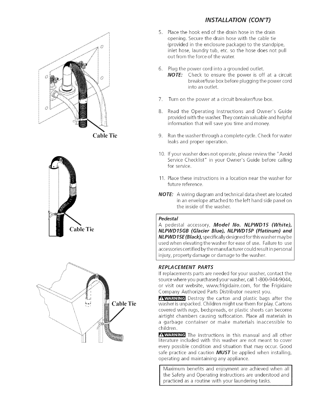
Cable Tie
Cable Tie
Cable Tie
iNSTALLATiON (CON'T)
Place the hook end of the drain hose in the drain
opening. Secure the drain hose with the cable tie
(provided in the enclosure package) to the standpipe,
inlet hose, laundry tub, etc. so the hose does not pull
out from the force of the water.
.Plug the power cord into a grounded outlet.
NOTE: Check to ensure the power is off at a circuit
breakedfuse box before plugging the power cord
into an outlet.
7. Turn on the power at a circuit breaker/fuse box.
8. Read the Operating Instructions and Owner's Guide
provided with the washer. They contain valuable and helpful
information that will save you time and money.
9. Run the washer through a complete cycle. Check for water
leaks and proper operation.
I 0. If you r washer does not operate, please review the "Avoid
Service Checklist" in your Owner's Guide before calling
for service.
11. Place these instructions in a location near the washer for
future reference.
NOTE: A wiring diagram and technical data sheet are located
in an envelope attached to the left hand side panel on
the inside of the washer.
Pedestal
A pedestal accessory, Model No. NLPWD15 (White),
NLPWD15GB (Glacier Blue), NLPWD15P (Platinum) and
NLPWD15E (Black), specifically designed for th iswash ermay be
used when elevating the washer for ease of use. Failure to use
accessoriescertified bythe manufacturer could result in personal
injury, property damage or damage to the washer.
REPLACEMENT PARTS
If replacements parts are needed for your washer, contact the
sourcewhere you purchased your washer, call 1-800-944-9044,
or visit our website, www.frigidaire.com, for the Frigidaire
Company Authorized Parts Distributor nearest you.
[_ Destroy the carton and plastic bags after the
washer is unpacked. Children might use them for play. Cartons
covered with rugs, bedspreads, or plastic sheets can become
airtight chambers causing suffocation. Place all materials in
a garbage container or make materials inaccessible to
children.
[_ The instructions in this manual and all other
literature included with this washer are not meant to cover
every possible condition and situation that may occur. Good
safe practice and caution MUST be applied when installing,
operating and maintaining any appliance.
Maximum benefits and enjoyment are achieved when all i
the Safety and Operating instructions are understood and 1
practiced as a routine with your laundering tasks.
