Frymaster H50 Series Users Manual SP Cover, Front
H50 Series to the manual e03664b3-0896-4086-aea1-178c6a522285
2015-02-09
: Frymaster Frymaster-H50-Series-Users-Manual-552447 frymaster-h50-series-users-manual-552447 frymaster pdf
Open the PDF directly: View PDF ![]() .
.
Page Count: 138 [warning: Documents this large are best viewed by clicking the View PDF Link!]
Frymaster, a member of the Commercial Food Equipment Service Association, recommends
using CFESA Certified Technicians.
24-Hour Service Hotline 1-800-551-8633 JUNE 2005
*8190001*
Service and Parts Manual
NOTICE
IF, DURING THE WARRANTY PERIOD, THE CUSTOMER USES A PART FOR THIS ENODIS
EQUIPMENT OTHER THAN AN UNMODIFIED NEW OR RECYCLED PART PURCHASED
DIRECTLY FROM FRYMASTER/DEAN, OR ANY OF ITS AUTHORIZED SERVICE CENTERS,
AND/OR THE PART BEING USED IS MODIFIED FROM ITS ORIGINAL CONFIGURATION, THIS
WARRANTY WILL BE VOID. FURTHER, FRYMASTER/DEAN AND ITS AFFILIATES WILL NOT BE
LIABLE FOR ANY CLAIMS, DAMAGES OR EXPENSES INCURRED BY THE CUSTOMER WHICH
ARISE DIRECTLY OR INDIRECTLY, IN WHOLE OR IN PART, DUE TO THE INSTALLATION OF
ANY MODIFIED PART AND/OR PART RECEIVED FROM AN UNAUTHORIZED SERVICE CENTER.
NOTICE
This appliance is intended for professional use only and is to be operated by qualified
personnel only. A Frymaster/DEAN Factory Authorized Service Center (FASC) or other qualified
professional should perform installation, maintenance, and repairs. Installation, maintenance,
or repairs by unqualified personnel may void the manufacturer’s warranty. See Chapter 1 of
this manual for definitions of qualified personnel.
NOTICE
This equipment must be installed in accordance with the appropriate national and local codes of
the country and/or region in which the appliance is installed. See NATIONAL CODE
REQUIREMENTS in Chapter 2 of this manual for specifics.
NOTICE TO U.S. CUSTOMERS
This equipment is to be installed in compliance with the basic plumbing code of the Building
Officials and Code Administrators International, Inc. (BOCA) and the Food Service Sanitation
Manual of the U.S. Food and Drug Administration.
NOTICE
Drawings and photos used in this manual are intended to illustrate operational, cleaning and
technical procedures and may not conform to onsite management operational procedures.
NOTICE TO OWNERS OF UNITS EQUIPPED WITH COMPUTERS
U.S.
This device complies with Part 15 of the FCC rules. Operation is subject to the following two
conditions: 1) This device may not cause harmful interference, and 2) This device must accept
any interference received, including interference that may cause undesired operation. While
this device is a verified Class A device, it has been shown to meet the Class B limits.
CANADA
This digital apparatus does not exceed the Class A or B limits for radio noise emissions as set
out by the ICES-003 standard of the Canadian Department of Communications.
Cet appareil numerique n’emet pas de bruits radioelectriques depassany les limites de classe A
et B prescrites dans la norme NMB-003 edictee par le Ministre des Communcations du Canada.

DANGER
Improper installation, adjustment, maintenance or service, and unauthorized alterations or
modifications can cause property damage, injury, or death. Read the installation, operating,
and service instructions thoroughly before installing or servicing this equipment. Only qualified
service personnel may convert this appliance to use a gas other than that for which it was
originally configured.
DANGER
No structural material on the fryer should be altered or removed to accommodate placement of
the fryer under a hood. Questions? Call the Frymaster/Dean Service Hotline at 1-800-551-8633.
DANGER
Adequate means must be provided to limit the movement of this appliance without depending
upon the gas line connection. Single fryers equipped with legs must be stabilized by installing
anchor straps. All fryers equipped with casters must be stabilized by installing restraining
chains. If a flexible gas line is used, an additional restraining cable must be connected at all
times when the fryer is in use.
DANGER
The front ledge of the fryer is not a step! Do not stand on the fryer. Serious injury can result
from slips or contact with the hot oil.
DANGER
Do not store or use gasoline or other flammable liquids or vapors in the vicinity of this or any
other appliance.
DANGER
Instructions to be followed in the event the operator smells gas or otherwise detects a gas leak
must be posted in a prominent location. This information can be obtained from the local gas
company or gas supplier.
DANGER
This product contains chemicals known to the state of California to cause cancer and/or birth
defects or other reproductive harm.
Operation, installation, and servicing of this product could expose you to airborne particles of
glasswool or ceramic fibers, crystalline silica, and/or carbon monoxide. Inhalation of airborne
particles of glasswool or ceramic fibers is known to the State of California to cause cancer.
Inhalation of carbon monoxide is known to the State of California to cause birth defects or other
reproductive harm.
DANGER
The crumb tray in fryers equipped with a filter system must be emptied into a fireproof container
at the end of frying operations each day. Some food particles can spontaneously combust if left
soaking in certain shortening material.
WARNING
Do not bang fry baskets or other utensils on the fryer’s joiner strip. The strip is present to seal
the joint between the fry vessels. Banging fry baskets on the strip to dislodge shortening will
distort the strip, adversely affecting its fit. It is designed for a tight fit and should only be
removed for cleaning.

H50 SERIES GAS FRYERS
TABLE OF CONTENTS
i
CHAPTER 1: Service Procedures
1.1 Functional Description.......................................................................................................1-1
The Electronic Ignition System..........................................................................................1-1
Interface Boards.................................................................................................................1-2
Thermostats........................................................................................................................1-5
1.2 Accessing Fryers for Servicing..........................................................................................1-5
1.3 Cleaning the Gas Valve Vent Tube....................................................................................1-5
1.4 Checking the Burner Manifold Gas Pressure.....................................................................1-6
1.5 Measuring Flame Current ..................................................................................................1-8
1.6 Replacing Fryer Components ............................................................................................1-8
1.6.1 Replacing the Controller or the Controller Wiring Harness ...............................1-8
1.6.2 Replacing the Temperature Probe or High-Limit Thermostat............................1-8
1.6.3 Replacing the Interface Board ............................................................................1-9
1.6.4 Replacing an Ignition Module ............................................................................1-9
1.6.5 Replacing an Ignitor Assembly.........................................................................1-10
1.6.6 Replacing or Cleaning a Combustion Air Blower ....................................................1-10
1.6.7 Replacing a Gas Valve......................................................................................1-13
1.6.8 Replacing a Burner Assembly...........................................................................1-14
1.6.9 Replacing the Frypot.........................................................................................1-15
1.6.10 Replacing Frypot Insulation and/or Upper Burner Rails ..................................1-16
1.7 Troubleshooting and Problem Isolation...........................................................................1-21
1.7.1 Ignition Failures................................................................................................1-21
1.7.2 Improper Burner Functioning ...........................................................................1-22
1.7.3 Improper Temperature Control.........................................................................1-24
1.7.4 Computer-Related Problems.............................................................................1-25
1.7.5 Filtration Problems............................................................................................1-26
1.7.6 Leakage.............................................................................................................1-29
1.7.7 Basket Lift Malfunctions ..................................................................................1-29
1.7.8 Interpretation of Digital Controller Lights........................................................1-32
1.8 Troubleshooting Guide ....................................................................................................1-32
Probe Resistance Chart ....................................................................................................1-37
1.9 Simplified Wiring Diagrams............................................................................................1-38
1.10 Principal Wiring Connections..........................................................................................1-43
1.11 Wiring Diagrams – Main ................................................................................................1-44
1.12 Wiring Diagrams – Transformer Boxes...........................................................................1-50
1.13 Wiring Diagrams – Basket Lifts ......................................................................................1-52
1.14 Wiring Diagrams – Filter Boxes......................................................................................1-55
1.14 Wiring Diagrams – Oil Return.........................................................................................1-56
CHAPTER 2: Parts List
2.1 Accessories ........................................................................................................................2-1

H50 SERIES GAS FRYERS
TABLE OF CONTENTS
ii
2.2 Basket Lift Assemblies and Component Parts .................................................................. 2-3
2.2.1 Bell Crank Basket Lifts...................................................................................... 2-3
2.2.2 Modular Basket Lifts.......................................................................................... 2-5
2.3 Blower Assemblies and Associated Components ............................................................. 2-7
2.4 Burner Ignition System Components and Associated Hardware ...................................... 2-9
2.5 Cabinet Assemblies and Component Parts...................................................................... 2-10
2.5.1 FPH150............................................................................................................. 2-10
2.5.2 FPH50 Batteries ............................................................................................... 2-11
2.5.3 FH150 and MJH150 ......................................................................................... 2-13
2.5.4 MJH50 Batteries............................................................................................... 2-14
2.5.5 FMH50 Batteries with Built-In Filtration......................................................... 2-15
2.5.6 Filter Magic II Add-On .................................................................................... 2-17
2.6 Casters, Legs, and Restraints........................................................................................... 2-19
2.7 Component Box Assemblies and Associated Component Parts ..................................... 2-20
2.8 Control Panel Assemblies, Flue Caps, Top Caps, and Related Components.................. 2-21
2.9 Controller Assemblies ..................................................................................................... 2-23
2.10 Door Assemblies .............................................................................................................2-24
2.11 Drain System Components.............................................................................................. 2-25
2.11.1 Filter Magic II Square Drain Components, Standard Configuration ............... 2-25
2.11.2 Filter Magic II Square Drain Components, Non-Standard Configurations...... 2-26
2.11.3 FootPrint III Square Drain Components, Standard Configuration................... 2-27
2.11.4 FootPrint III Square Drain Components, Rear Flush Configuration................ 2-28
2.11.5 FootPrint III Square Drain Components, Foodmaker Configuration............... 2-29
2.12 Drain Valves, Drain Valve Assemblies, and Associated Parts ....................................... 2-30
2.12.1 Drain Valves and Drain Extensions ................................................................. 2-31
2.12.2 MJH50 Dual Vat (1-inch) Drain Valve Assemblies......................................... 2-31
2.12.3 FMH50 Dual Vat (1-inch) Drain Valve Assemblies........................................ 2-32
2.12.4 FMH50 Full Vat (1¼-inch) Drain Valve Assembly......................................... 2-33
2.12.5 FPH50 Dual Vat (1-inch X 1¼-inch) Valve Assemblies ................................. 2-34
2.12.6 FPH50 Full Vat (1¼-inch) Valve Assemblies.................................................. 2-35
2.13 Filtration Systems and Component Parts (Other Than Drain Components)................... 2-36
2.13.1 Filter Magic II/Single FootPrint III Filter Pan Assembly ................................ 2-36
2.13.2 FootPrint III Filter Pan Assembly .................................................................... 2-37
2.13.3 FootPrint III Filter Base Assemblies................................................................ 2-38
2.13.4 Filter Magic Oil Return Plumbing Components (Including Pump & Motors) 2-39
2.13.5 FootPrint III Filter Motors and Pump Plumbing Components......................... 2-41
2.13.6 FootPrint III with Power Shower Oil Return Plumbing Components.............. 2-43
2.13.7 FootPrint III with Rear Flush Oil Return Plumbing Components, Standard ... 2-45
2.13.8 FootPrint III with Rear Flush Oil Return Plumbing Components, KFC.......... 2-47
2.13.9 FPH150-2 Oil Return Plumbing....................................................................... 2-49
2.13.10 Oil Return Handle Assembly, Filter Magic & Standard FootPrint III ............. 2-51

H50 SERIES GAS FRYERS
TABLE OF CONTENTS
iii
2.13.11 Power Shower Assemblies (All Systems).........................................................2-52
2.13.12 Oil Disposal Systems Plumbing........................................................................2-53
2.13.13 Assembly Wand Plumbing (Japan)...................................................................2-55
2.13.14 Oil Disposal Wand Assembly...........................................................................2-56
2.14 Frypot Assemblies and Component Parts........................................................................2-56
2.14.1 Replacement Frypots and Frypot Insulation Kits .............................................2-56
2.14.2 Full Vat Frypot Assembly, Component Parts ...................................................2-57
2.14.3 Dual Vat Frypot Assembly, Component Parts..................................................2-59
2.15 Gas Supply System Assemblies and Component Parts ...................................................2-61
2.15.1 FM/MJH50 Gas Manifold Assemblies .............................................................2-61
2.15.2 Gas Valves, Gas Lines, and Fittings .................................................................2-63
2.16 Probe, Probe Guard, and Thermostat...............................................................................2-65
2.18 Relays, Transformers, Wiring Assemblies, and Related Parts ........................................2-66
2.18.1 Filter Box Components.....................................................................................2-66
2.18.2 Transformer Box Components..........................................................................2-67
2.19 Wiring Harnesses, Wiring Assemblies, and Plug Assemblies.........................................2-69
2.20 Wiring Connectors and Pin Terminals.............................................................................2-73

H50 SERIES GAS FRYERS
CHAPTER 1: SERVICE PROCEDURES
1-1
Inside the Ignition Module
TD
Out to
Gas Valve
To Alarm
25 V +
GND
HV
Ignition Wire Flame Sensor
Coil
1.1 Functional Description
H50 Series fryers contain a welded stainless steel frypot that is directly heated by a high efficiency
infrared burner system requiring approximately 43% less energy than conventional burners to cook
the same volume.
Self-contained combustion chambers (referred to as “burners”) are fitted into rails attached to the
sides of the frypot, one on each side. Each combustion chamber is fitted with special ceramic tiles
that are heated by the burning of a forced air/gas mixture. The tiles transfer their heat to the frypot
by means of infrared radiation, providing much more constant and uniform heat dispersion over the
surface of the frypot than do conventional burners. Because less heat is lost to the atmosphere in the
process, compared to “open-burner” designs, less fuel is required to achieve and maintain a given
frypot temperature.
In full vat units, gas flow to both of the burners is regulated by one electromechanical gas valve. In
dual vat units, each burner has its own valve. All fryers in this series are equipped with 24VAC gas
valve systems, and all are configured with electronic ignition.
THE ELECTRONIC IGNITION SYSTEM
An ignition module mounted in the component box or
“shield” (located behind the control panel) is connected to
an ignitor assembly at the burner. The ignition module
performs four important functions: it provides fuse
protection for the 24-volt circuit, provides an ignition
spark, supplies voltage to the gas valve, and proofs the
burner flame. The module contains a 4-second time delay
circuit and a coil that activates the gas valve. Three types
are in use. A closed-box design is used in most fryers, but
in some fryers built for export the module resembles an
interface board. A single dual-spark module is used on
current production full-vat fryers. Two single-spark
modules were used on full-vat fryers built before August
2000. All dual-vat fryers use two single-spark modules.
The ignitor assembly consists of a spark plug, an enrichment tube, and a flame sensor.
At start-up, the power switch is placed in the ON position, supplying approximately 12-volts DC to
the heat control circuitry in the controller or computer and to one side of the heat relay coils on the
interface board. If resistance in the temperature probe indicates the temperature in the frypot is
below 180ºF (82ºC), the current flows through a melt cycle circuit where a timer switch alternately
closes for 6 seconds and opens for 24 seconds. If the temperature is 180ºF (82ºC) or above, the
current flows through a heat circuit, bypassing the timer switch. In either case, ground is supplied
to
1-2
the other leg of the heat relay coils, which then close electronic switches in the 24 VAC circuit to
provide current to the ignition module. Circuitry in the ignition module sends 24 VAC to the gas
valve via a normally closed high-limit switch (and, in fryers with built-in filtration systems, a
normally closed drain safety switch). Simultaneously, the module causes the ignitor to spark for 4
seconds to light the burner. A flame sensor verifies the burner ignition by measuring the flow of
microamps through the flame. If the burner does not light (or is extinguished), current to the
ignition module is cut, the gas valve closes, and the ignition module “locks out” until the power
switch is turned off and then back on. A probe monitors the temperature in the frypot. When the
programmed setpoint temperature is reached, resistance in the probe causes the heat cycle circuitry
in the controller to cut off current flow through the heat relay. This in turn cuts off the 24 VAC to
the ignition module, causing the gas valve to close.
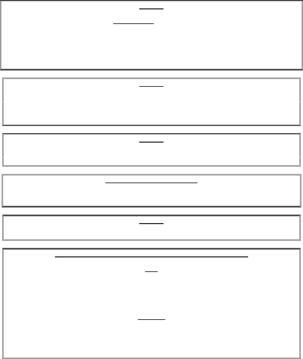
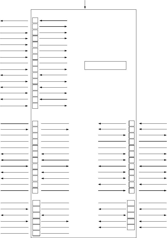
INTERFACE BOARDS
All fryers in this series have an interface board located in the component box located behind the
control panel. The interface board provides a link between the controller/computer and the fryer’s
individual components without requiring excessive wiring, and allows the controller to execute
commands from one central point. The H50 Series of fryers has been in production since 1983.
Consequently, servicers are likely to encounter three different interface board designs. Although the
boards differ slightly in appearance, basic functioning and electrical connections are the same from
one to another. In the earlier design 806-3398 interface board (used between June 1996 and July
1999), the diagnostic LEDs are arrayed in a row across the bottom of the board as shown in the left-
hand illustration below. In later design 806-3398 interface boards (and in the 106-0396 interface
boards that replaced them in current production fryers), the LEDs (labeled D1 though D7) are
scattered around the board as shown in the right-hand illustration. The primary difference between
the earlier design boards and the later design boards is the combining of the separate blower motor
relay (K4) and the heat relays (K1 and K2) into a pair of replaceable relays (K2 and K3) in the latter.
Also, the 106-0386 interface board has an additional fuse located in the upper right hand corner.
Prior to June 1996, a board with replaceable relays very similar in appearance to the 106-0386 board
was used. It is distinguished from the 106-0386 board by the absence of fuses.
NOTE: Although the printing on many boards indicates 2 Amp fuses, 3 Amp fuses (P/N 807-3843)
must be used.
K4
K1 K2
SOUND
1
2
3
GND
GND
V2D
PWR
AD
AS
V2S
GND
V1D
PWR
ALR
V1S
GND GV PWR AL 12V AIR 24V AL PWR GV GND
J2
EARLIER DESIGN INTERFACE BOARD P/N 806-3398
GND
12 6 3 45
J3
3 6 9 12
2 5 8 11
1 4 7 10
J1
3 6 9 12
2 5 8 11
1 4 7 10
15
12963
14
11852
13
10741
BLOWER
MOTOR
RELAY
K3 K5
HEAT
RELAY
HEAT
RELAY
K4
K1
SOUND
1
2
3
GND
GND
V2D
PWR
AD
AS
V2S
GND
GV
PWR
12V AIR
24V
PWR
GND
V1D
PWR
ALR
V1S
GV
GND
J2
LATER DESIGN INTERFACE BOARDS P/N 806-3398 and 106-0386
GND
J3
3 6 9 12
2 5 8 11
1 4 7 10
J1
3 6 9 12
2 5 8 11
1 4 7 10
15
12963
14
11852
13
10741
K2 K3
HEAT
RELAY
AND
BLOWER
MOTOR
RELAY
D1
D2
D3
D4
D6 D7
Blower
Motor
2 Amp
D5
HEAT
RELAY
AND
BLOWER
MOTOR
RELAY
F2 Ignition
2 AMP Module
This Fuse is NOT
present on 806-3398 IFB.
1-3
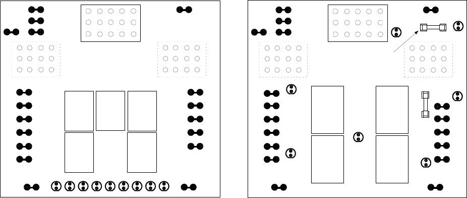
FREQUENTLY USED TEST POINTS FOR INTERFACE BOARDS 806-3398 AND 106-0386
Meter
Test Setting Pins Results
12VAC Power to Controller 50VAC Scale 1 and 3 on J3 or J2 12-18
24VAC Power to Right Module 50VAC Scale 8 on J3 and GROUND 22-28
24VAC Power to Left Module (if present) 50VAC Scale 8 on J1 and GROUND 22-28
120 VAC Power 250VAC Scale 11 on J3 and GROUND 110-125
120 VAC Power to Blowers 250VAC Scale 12 on J3 and GROUND 110-125
24VAC Power to Full- or Right-vat High-Limit 50VAC Scale 9 on J3 and GROUND 22-28
24VAC Power to Left High-Limit (if present) 50VAC Scale 9 on J1 and GROUND 22-28
Probe Resistance (Full- or Right-vat) *R x 1000 OHMS 2 and 6 on J3 or 13 and 14 on J2 **
Probe Resistance (Left - if present) * R x 1000 OHMS 2 and 6 on J1 or 14 and 15 on J2 **
Probe Isolation R x 1000 OHMS 6 on J1 or J3 and GROUND ***
High-Limit Continuity (Full- or Right-vat) R x 1 OHM 9 on J3 and Wire 13C on Gas Valve 0
High-Limit Continuity (Left - if present) R x 1 OHM 9 on J1 and Wire 12C on Gas Valve 0
** Disconnect 15-pin harness from controller before testing probe circuit.
** See Probe Resistance Chart at end of chapter.
*** 5 mega-Ohms or greater.
These standard interface boards are also used in a number of fryer types besides the H50 Series. The
information contained in this section applies to H50 Series applications ONLY.
Earlier design 806-3398 boards (used from June 1996 through July 1999) contain two heat relays
(K1 and K2) that switch 24VAC to the ignition and gas valve circuits when the computer/controller
heat logic circuit calls for heat. Relay K4 switches 120VAC to the blower motor when either K1 or
K2 closes. The relays on these boards are soldered on – if one fails, the whole board must be
replaced.
The later design 806-3398 (and 106-0386 boards that replaced them in current production fryers)
have only two relays. In this design, K2 and K3 are double-pole-double throw (dpdt) relays that
supply 24VAC to the ignition and gas valve circuits, as well as 120VAC to the blower motor. The
relays on this board plug into sockets. If a relay fails, that relay can be replaced.
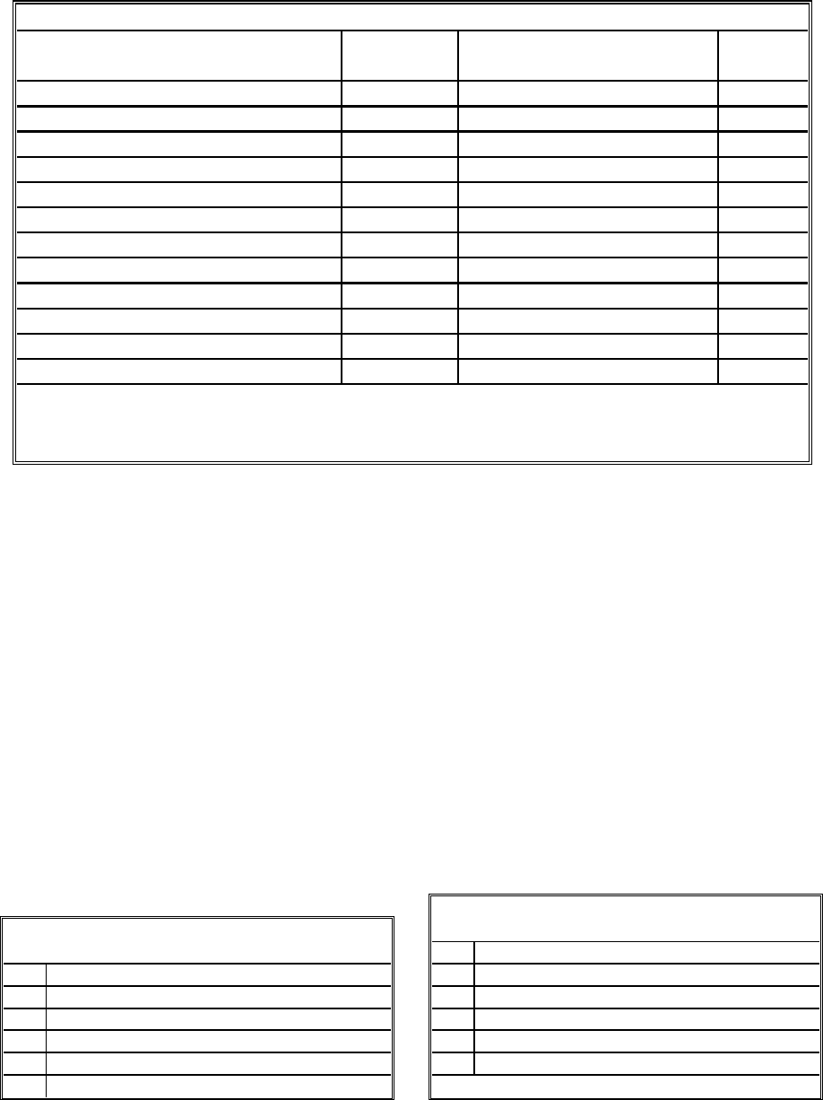
The tables below identify the diagnostic LEDs and their meaning.
12V Indicates 12 VAC from transformer
24V Indicates 24 VAC from transformer
GV Indicates 24 VAC to gas valve (left or right)
PWR Indicates 24 VAC to module (left or right)
AL Indicates module lock-out (left or right)
AIR CE and Japanese units only: air switch closed
EARLIER DESIGN INTERFACE BOARD
LED DIAGNOSTIC LIGHTS
D1 24 VAC to left gas valve (dual vat only)
D2 24 VAC to left ignition module
D3 24 VAC from transformer
D4 24 VAC to right ignition module
D5 24 VAC to gas valve (right valve if dual vat)
D6 12 VAC from transformer
D7 CE and Japanese units only: air switch closed
LATER DESIGN INTERFACE BOARD
LED DIAGNOSTIC LIGHTS
1-4
CURRENT FLOW THROUGH
INTERFACE BOARDS 806-3398 AND 106-0386
(H50 APPLICATION)
1
2
3
4
5
6
7
8
9
10
11
12
J3
J2 PIN 1
J2
1
2
4
5
6
7
8
9
10
11
12
13
14
15
1
2
3
4
5
6
7
8
9
10
11
12
J1
LEFT VAT FULL OR RIGHT VAT
INTERFACE BOARD
12 VAC TO CPTR J3 PIN 1
GROUND GROUND
3
COMPUTER (12 VAC) J3 PIN 3
COMPUTER RT HT RELAY
COMPUTER LT HT RELAY
COMPUTER RT BL RELAY
NOT USED NOT USED
COMPUTER LT BL RELAY
RT ALARM OUT
** ALR (RIGHT)
COMPUTER SOUND DEVICE
LT ALARM OUT
*AD (LEFT)
COMPUTER J3 PIN 6
COMPUTER
COMPUTER J1 PIN 6
J1 PIN 2 & J3 PIN 2
NOT USED NOT USED
NOT USEDNOT USED
NOT USED NOT USED
TEMP PROBE J2 PIN 15
BASKET LIFT (DN)
24 VAC IN
LT BL RELAY
MAIN GAS VALVE
BASKET LIFT (UP) LT BL RELAY
12 VAC XFMR
J2 PIN 14 TEMP PROBE
J2 PIN 3 12 VAC XFMR
NOT USED NOT USED
J2 PIN 13 TEMP PROBE
RT BL RELAY BASKET LIFT (DN)
24 VAC IN
MAIN GAS VALVE
RT BL RELAY BASKET LIFT (UP)
120 VAC IN
BLOWER XFMR BOX
COMPUTER 12 VDC TO RELAYS
NOT USEDNOT USED
PWR via LT HT RELAY
V2D
NOT USED NOT USED
BLOWER via K4 (old)
or K2/K3 (new)
PWR via RT HT RELAY
V1S OR V1D
NOT USED NOT USED
J2 PIN 14TEMP PROBE
V2D
PWR
AD
AS
V2S
GND
V1D
PWR
ALR
V1S
GND
MOD 25V GROUND GROUND
MOD V2D
MOD 25V TERM
DRAIN SWITCH (OPT) J2 PIN 12
NOT USED NOT USED
NOT USED NOT USED
GROUND MOD 25V GROUND
J3 PIN 9 MOD V1D *
MOD 25V TERM
J3 PIN 8 via RT HT RELAY
DRAIN SWITCH (OPT)
J2 PIN 10
MOD V1S **
*
** Dual Vat configurations
** Full Vat configurations
via HLS via HLS
J3 PIN 9
J1 PIN 9
J1 PIN 8 via LT HT RELAY
NOT USED NOT USED

1-5
THERMOSTATS
All fryers in the H50 Series have temperature probes located on the front centerline of each frypot.
(Dual-vat frypots have two probes, one in each vat.) In this type thermostat, the probe resistance
varies directly with the temperature. That is, as the temperature rises, so does resistance, at a rate of
approximately 2 ohms for every 1º F. Circuitry in the controller monitors the probe resistance and
controls burner firing when the resistance exceeds or falls below programmed temperatures
(setpoints). The temperatures are programmed by means of a keypad on the face of the controller.
H50 Series fryers are also equipped with a high-limit thermostat. In the event that the fryer fails to
properly control the oil temperature, the high-limit thermostat prevents the fryer from overheating to
the flash point. The high-limit thermostat acts as a normally closed power switch that opens when
exposed to temperatures above 425ºF to 450ºF (218ºC to 232ºC). The different types of thermostats
have different part numbers for CE and Non-CE models, and are not interchangeable.
1.2 Accessing Fryers for Servicing
DANGER
Moving a fryer filled with cooking oil may cause spilling or splattering of the hot
liquid. Drain the fryer before attempting to relocate a fryer for servicing.
1. Shut off the gas supply to the unit. Unplug the power cords. Disconnect the unit from the gas
supply.
2. Remove any attached restraining devices.
3. Relocate the fryer for service accessibility.
4. After servicing is complete, reconnect the unit to the gas supply, reattach restraining devices, and
plug in the electrical cords.
1.3 Cleaning the Gas Valve Vent Tube
1. Set the fryer power switch and the gas valve to the OFF position.
2. Carefully unscrew the vent tube from the gas valve. NOTE: The vent tube may be straightened
for ease in removal.
3. Pass a piece of ordinary binding wire (.052 inch diameter) through the tube to remove any
obstruction.
4. Remove the wire and blow through the tube to ensure it is clear.
5. Reinstall the tube and bend it so that the opening is pointing downward.
1-6
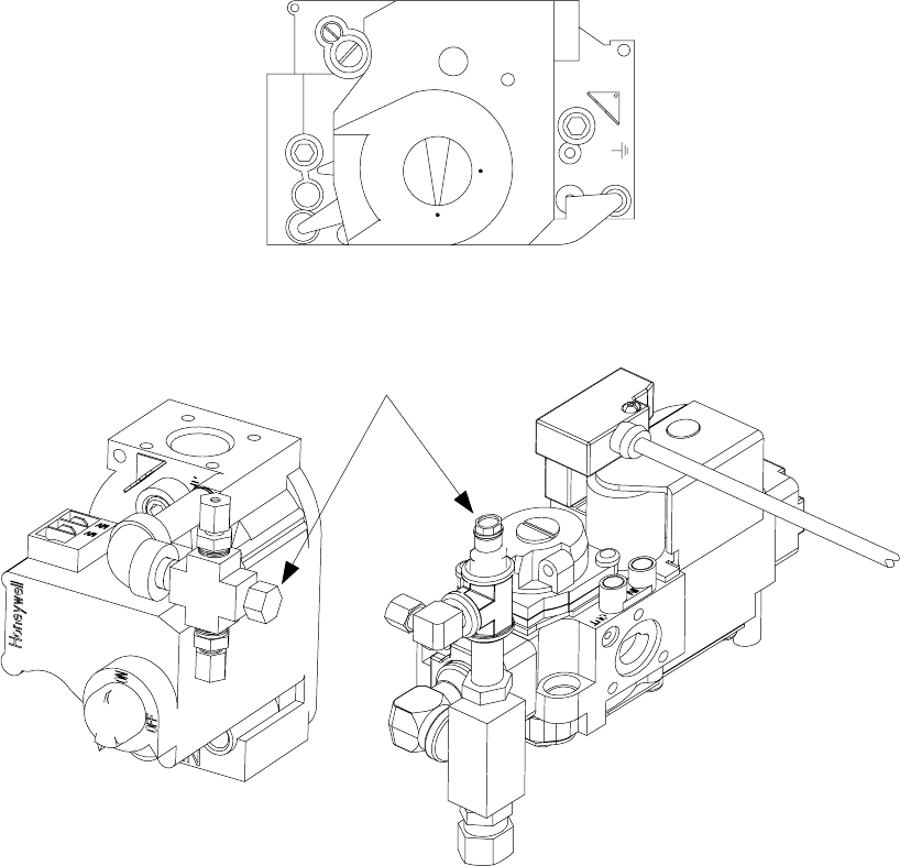
1.4 Checking the Burner Manifold Gas Pressure
1. On non-CE fryers, ensure that the gas valve knob is in the OFF position.
Honeywell
ON
OFF
2. Remove the pressure tap plug from the gas valve assembly.
Typical Non-CE
Valve Assembly Typical CE Valve
Assembly
Pressure Tap Plug
2. Insert the fitting for a gas pressure-measuring device into the pressure tap hole.
3. On non-CE fryers only, place the gas valve in the ON position.
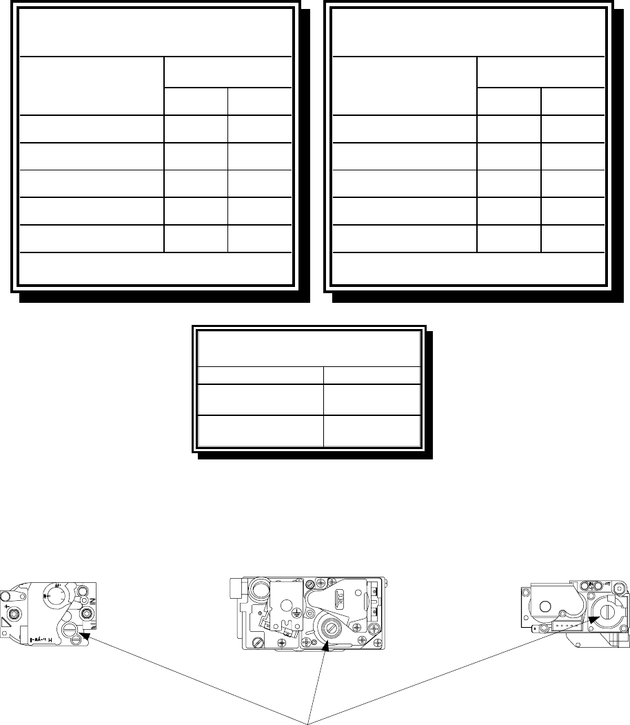
4. Place the fryer power switch in the ON position. When the burner has lit and burned steadily for
at least one minute, compare the gas pressure reading to the pressure for the corresponding gas in
the appropriate table found on the following page. The tables list the burner manifold gas
pressures for each of the gas types that can be used with this equipment.
1-7
Gas
Single
Vat
Dual
Vat
Natural Gas Lacq
(G20) under 20 mbar 77
Natural Gas Gronique *
(G25) under 25 mbar 10 10
Natural Gas Gronique
(G25) under 20 mbar 10 10
Butane/Propane
(G30) at 28/30 or 50 mbar 17 17
Propane
(G31) under 37 or 50 mbar 20 20
CE Standard
Burner Manifold Gas Pressures
for Fryers Manufactured After April 1999
Pressure (mbar)
* Belgian G25 = 7,0 mbar (single or dual)
Gas
Single
Vat
Dual
Vat
Natural Gas Lacq
(G20) under 20 mbar 76,5
Natural Gas Gronigue *
(G25) under 25 mbar 10 9
Natural Gas Gronigue
(G25) under 20 mbar 10 9
Butane
(G30) at 28/30 or 50 mbar 17 16,5
Propane
(G31) under 37 or 50 mbar 20,2 18,5
CE Standard
Burner Manifold Gas Pressures
for Fryers Manufactured Through April 1999
Pressure (mbar)
* Belgian G25 = 7,0 mbar (single) or 6,5 (dual)
Gas Pressure
Natural 3" W.C.
0.73 kPa
Propane 8.25" W.C.
2.5 kPa
Non-CE Standard
Burner Manifold Ga s Pre ssures
5. To adjust the burner gas pressure, remove the cap from the gas valve regulator and adjust to the
correct pressure.
Non-CE
Valve Earlier Model CE Valve Later Model
CE Valve
GAS VALVE REGULATOR CAP
6. Place the fryer power switch (and the gas valve in non-CE fryers) in the OFF position. Remove
the fitting from the pressure tap hole and reinstall the pressure tap plug.
1-8
1.5 Measuring Flame Current
When the burner flame is properly adjusted, it will produce a current between 2.5 μA and 3.5 μA.
Flame current is measured by placing a microamp (not milliamp) meter in series with the sensing
wire on the ignitor. This is accomplished as follows:
1. Place the fryer power switch in the OFF position.
2. Disconnect the sensing wire from one of the burner ignitors and connect it to the positive lead of
the meter. Connect the negative lead of the meter to the terminal from which the sensing wire
was removed.
3. Place the fryer power switch in the ON position to light the burners. Wait at least one minute
after the frypot temperature reaches 200°F (93°C) before checking the reading. NOTE: The
closer the unit is to normal operating temperature, the more accurate the reading will be.
1.6 Replacing Fryer Components
1.6.1 Replacing the Controller or the Controller Wiring Harness
1. Disconnect the fryer from the electrical supply.
2. Remove the two screws in the upper corners of the control panel and swing the panel open from
the top, allowing it to rest on its hinge tabs.
3. Disconnect the wiring harness from the back of the controller and, if replacing the harness,
disconnect it from the interface board.
4. Disconnect the ground wire from the controller, and remove the controller by lifting it from the
hinge slots in the control panel frame.
5. Reverse the procedure to install a new controller or wiring harness. NOTE: Ensure that the fer-
rite bead (black ring) in the harness is at the controller end.
1.6.2 Replacing the Temperature Probe or High-Limit Thermostat
1. Disconnect the fryer from the electrical supply.
2. Drain cooking oil below the level of the probe or thermostat.
3. Remove the screws from the upper corners of the control panel and swing the panel open from
the top, allowing it to rest on its hinge tabs.
4. Unplug the controller wiring harness from the back of the controller.
5. Remove the controller by lifting it from the hinge slots in the control panel frame.
6. If the fryer has a built-in filtration system, loosen the bolt securing the oil return handle to the oil
return operating rod.
1-9
7. Disconnect the ignition cables from the ignitors by grasping the boots and gently pulling toward
you.
8. Remove the component box mounting screws.
9. Rotate the top of the component box out of the frame and carefully pull it out enough to
disconnect the wiring harness plug(s) from the back of the box.
10. Remove the box and set it aside.
11. Make a note of the location of the existing wires. Using a pin-pusher, disconnect the tempera-
ture probe wires (or high-limit thermostat wires) from the connector plug.
12. Unscrew and remove the temperature probe (or high limit thermostat) from the frypot.
13. Apply Loctite® PST56765 pipe thread sealant or equivalent to the replacement part threads.
14. Screw the replacement part into the frypot and torque to 180 inch-pounds.
15. Connect the wires from the new component to the connector plug, referring to the note made in
step 11.
16. Reverse steps 1 through 9 to complete the procedure.
1.6.3 Replacing the Interface Board
1. Remove the component box per steps 1 through 10 of Section 1.6.2.
2. Unplug the controller wiring harness from the interface board.
3. Disconnect the wires attached to the interface board, marking or making a note of the wires and
terminals to facilitate reconnection.
4. Remove the nuts at each corner of the interface board and pull it from the studs.
5. Reverse the procedure to install the replacement board, being sure to reinstall the spacers behind
the interface board.
1.6.4 Replacing an Ignition Module
1. Disconnect the fryer from the electrical supply.
2. Remove the screws from the upper corners of the control panel and swing the panel open from
the top, allowing it to rest on its hinge tabs.
3. Disconnect the wires from the ignition module, marking or making a note of the wires and
terminals to facilitate reconnection.
4. Remove the four ignition module screws and pull the module from the component box.

1-10
5. Reverse the procedure to install the replacement module.
1.6.5 Replacing an Ignitor Assembly
DANGER
Drain the frypot or remove the handle from the drain valve before proceeding further.
1. Disconnect the fryer from the electrical supply.
2. Disconnect the ignition cable from the ignitor by grasping the boot and gently pulling toward
you.
3. Remove the sheet metal screw securing the ignitor to the mounting plate and pull the ignitor
from the fryer.
4. Reverse the procedure to install the replacement ignitor.
1.6.6 Replacing or Cleaning a Combustion Air Blower
A sheet metal shield or shield assembly prevents inadvertent access to the blower assembly. The
specific design varies depending upon the particular configuration of the fryer and the country for
which manufactured, but in all cases, the shield is attached to the cabinet framing by sheet metal
screws. Remove the screws that secure the shield or shield assembly to the cabinet framing and pull
the shield out of the fryer to expose the combustion air blower assembly.
1. Disconnect the blower wiring harness and remove the blower assembly mounting nuts.
2. Remove the three fasteners that secure the blower motor assembly to the blower housing, and
separate the two components.
Wiring connection
Blower
assembly
mounting
nuts

1-11
Remove these fasteners.
(On black-colored FASCO
blowers there are three
nuts. On silver-colored
KOOLTRONICS blowers
there are three screws.)
3. Wrap the motor with plastic wrap to prevent water from entering it. Spray degreaser or
detergent on the blower wheel and the blower housing. Allow it to soak for five minutes. Rinse
the wheel and housing with hot tap water, then dry with a clean cloth.
Wrap the motor and
wires with plastic wrap
or a plastic bag.
BLOWER HOUSING BLOWER WHEEL
4. Remove the plastic wrap from the blower motor assembly. Reassemble the blower motor
assembly and blower housing. Reinstall the blower assembly in the fryer.
5. Reinstall the blower shield or shield assembly.
6. Light the fryer in accordance with the procedure described in Chapter 3, Section 3.1 of the H50
Series Installation and Operation Manual (P/N 819-5000).
7. After the burners have been lit for at least 90 seconds, observe the flames through the burner
viewing ports located on each side of the combustion air blower.
1-12
The air/gas mixture is properly adjusted when the burner manifold pressure is in accordance with the
applicable table on page 1-7 and the burners display a bright orange-red glow. If a blue flame is
observed, or if there are dark spots on a burner face, the air/gas mixture requires adjustment.
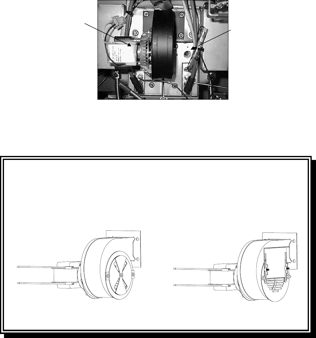
Adjusting Air/Gas Mixture
Non-CE Units and CE Units Built After April 1999
On the side of the blower housing opposite the motor is a plate with one or two locking nuts.
Loosen the nut(s) enough to allow the plate to be moved, then adjust the position of the plate to open
or close the air intake opening until a bright orange-red glow is obtained. Carefully hold the plate in
position and tighten the locking nut(s).
TYPICAL NON-CE BLOWER ASSEMBLY TYPICAL CE BLOWER ASSEMBLY
ON UNITS BUILT AFTER APRIL 1999
Right
Viewing
Port
Left Viewing
Port is Behind
Motor
(NOTE: Blower
shield omitted
for clarity.)

1-13
Adjusting Air/Gas Mixture
CE Units Built Through April 1999
CE units built through April 1999 are equipped with a shield assembly in front of the blowers. An
air shutter plate on the face of the shield assembly regulates the amount of airflow to the blower in-
take. To adjust the shutter plate, loosen the locking screws and slide the shutter to the left or right as
necessary to obtain a bright orange-red glow. Carefully hold the shutter plate in position and tighten
the locking screws.
TYPICAL CE BLOWER SHIELD ASSEMBLY
ON UNITS BUILT THROUGH APRIL 1999
1.6.7 Replacing a Gas Valve
DANGER
Drain the frypot or remove the handle from the drain valve before proceeding further.
1. Disconnect fryer from electrical and gas supplies.
2. Disconnect the wires from the gas valve terminal block, marking each wire to facilitate its
reconnection.
3. Remove the vent tube and the enrichment tube fitting from the valve.
4. Disconnect the flexible gas line(s).
5. Carefully unscrew the valve from the manifold. NOTE: Some models may have the valve
attached to the manifold by means of a pipe union. In such cases, remove the valve by
uncoupling the union.
6. Remove all fittings from the old gas valve and install them on the replacement valve, using
Loctite® PST56765 or equivalent pipe thread sealant.
7. Apply Loctite® PST 56765 or equivalent pipe thread sealant to the threads of the manifold (or
union). Reverse steps 1-5 to install the replacement gas valve.

1-14
1.6.8 Replacing a Burner Assembly
DANGER
Drain the frypot or remove the handle from the drain valve before proceeding further.
1. Disconnect the unit from the electrical and gas supplies.
2. Remove the combustion air blower per the procedure found in Section 1.6.6.
3. Remove the four nuts from the air plenum assembly and pull the assembly straight out toward
you until it clears the burner tubes.
NOTE: On a dual vat fryer, it will be necessary to remove the drain valve handles before the
plenum can be removed.
4. Disconnect the ignition cables from the ignitors by grasping their boots and pulling toward you.
5. Disconnect the gas lines and enrichment tubes from the burner orifices and ignitor assemblies.
6. Remove the four ¼” (6mm) nuts securing the outer front covers to the frypot assembly.
7. Remove the sheet metal screws at the top of the outer front covers and pull the covers straight
out toward you until clear of the mounting studs.
8. Remove the washers and tubular spacers from the mounting studs, then pull the inner covers
straight out toward you until clear of the mounting studs.
9. Grasp the burner firmly and pull it toward you until it clears the burner channels, taking care not
to damage the ceramic tiles in the process.
10. Clean all debris from the burner channels and combustion area.
11. Inspect the upper and lower burner rails for cracked or burned-out welds.
a. If the welds in the lower rail are cracked or burned out, the frypot must be replaced. Refer to
Section 1.6.9 for procedure.
b. If the welds in the upper rail are cracked or burned out, the upper rail must be replaced.
Refer to Section 1.6.10 for procedure.
12. Place a new insulating strip along the top, rear, and bottom edge of the burner and carefully slide
it straight into the rails.
NOTE: Use P/N 826-0931 for full vat frypots and P/N 826-0932 for dual vat frypots.
13. Reverse steps 1 through 9 to reassemble the components.
14. Fill the frypot with oil. Turn the fryer on, turn off or bypass the melt cycle, and operate the unit
for at least 10 minutes.
1-15
15. Examine the burner flame. The color and intensity on both sides should be the same.
16. Use an inspection mirror to check for leaks in areas that cannot be directly observed.
17. If a leak is detected, tighten all the lower insulation retainer nuts, allow the frypot to run for five
additional minutes, and repeat steps 15 and 16.
18. If the leak persists, use a rubber hammer and a small block of wood to tap the corners of the
lower combustion chamber insulation retainers. Repeat steps 15 through 17. Repeat this step
until no leakage is detected.
1.6.9 Replacing the Frypot
1. Drain cooking oil from the frypot.
2. Remove all accessories, e.g., frypot covers, basket lift arms, etc. from the fryer.
4. Disconnect the fryer from gas and electrical supplies.
5. Remove the screws from the topcap above the control panel and lift it up and off the fryer(s).
6. Remove the screws from the upper left and right corners of the control panel. Open the panel,
disconnect the controller wiring harness and ground wire. Remove the controller from the fryer.
7. Disconnect the ignition wires from the ignitor plugs by grasping their boots and pulling toward
you.
8. Remove the screws securing the component box to the frame, and then rotate the top of the box
forward and out of the fryer enough to disconnect the wiring harness connector plug(s) on the
rear of the box. Set the component box aside.
9. Using a pin pusher, remove the temperature probe and high-limit thermostat wires from the
plug(s), marking each wire to facilitate re-assembly.
10. On fryers with built-in filtration, remove the cover from the safety drain switch, disconnect the
wires from the switch, and pull them out of the switch box.
11. On fryers with built-in filtration, remove the section(s) of square drain from the drain valve(s) of
the frypot to be removed.
12. Disconnect the gas lines and enrichment tubes from the burner orifices and ignitor assemblies.
13. Remove the frypot hold down bracket.
14. Remove the screws from the flue cap sides and back and lift it clear of the fryer(s).
15. On units equipped with built-in filtration, disconnect the oil return line(s) from the frypot to be
removed.

1-16
16. Carefully lift the frypot from the fryer cabinet.
17. Remove the drain valve(s), temperature probe(s), high-limit thermostat(s), and ignitor
assemblies. Inspect each of these components carefully and install them in the replacement
frypot if they are in serviceable condition. Use Loctite® PST56765 sealant or equivalent on
component threads.
NOTE: Some servicers, based upon their experience, recommend that probes and thermostats
be replaced whenever a frypot is replaced, but this remains the customer’s decision.
18. Reverse steps 1-16 to reassemble fryer.
19. Perform steps 14 through 18 of Section 1.6.8 to ensure that there are no leaks in the burner insu-
lation.
CAUTION
Before installing the temperature probe, high-limit thermostat, and drain valve on the
replacement frypot, clean their threads and apply Loctite® PST56765 thread sealant
or equivalent.
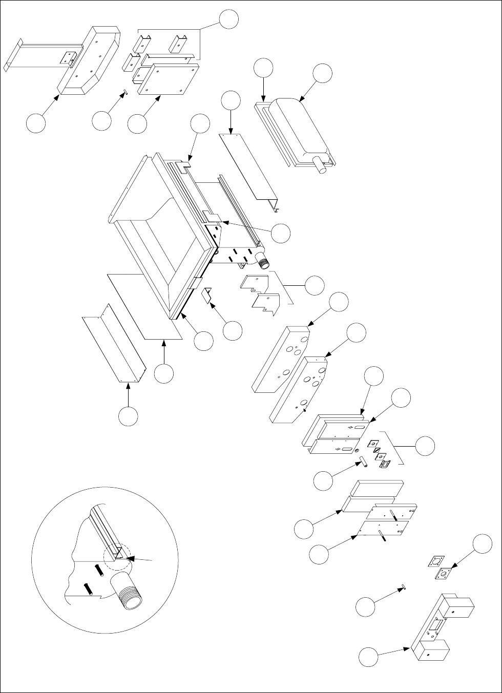
1.6.10 Replacing Frypot Insulation and/or Upper Burner Rails
NOTE: Replacing the burner rails requires completely tearing down the frypot and installing new
frypot insulation. Refer to the frypot exploded view on page 1-18 for component identification. A
CD containing a PowerPoint presentation detailing the procedure is also available (P/N 819-5805).
1. Remove the frypot per Section 1.6.9.
2. Remove the burner assemblies (1).
3. Remove insulation retainers and blanket insulation (2).
4. Remove the upper oil zone insulation bracket and upper oil zone insulation (3).
5. Remove the plenum (4).
6. Remove the front lower combustion chamber insulation retainer and insulation (5), and the front
lower combustion chamber inner insulation retainer and insulation (6).
NOTE: Full vat units have two-piece insulation retainer and insulation components. Dual vat
units have one-piece components.
7. Remove the upper combustion chamber insulation retainer and insulation (7).
8. Remove the inner upper combustion chamber insulation retainer and insulation (8).
9. Remove the rear lower combustion chamber retainers, back, and insulation (9).
NOTE: Full vat units have two-piece backs and four retainers. Dual vat units have one-piece
backs and two retainers.
1-17
10. Remove the flue assembly (10).
11. Remove the upper burner rails (11).
NOTE: For the following steps, refer to the frypot exploded view on page 3-19 for component iden-
tification.
12. Remove any residual insulation, sealant, and/or oil from the exterior of the frypot.
13. Place the “L” shaped pieces of combustion chamber insulation (1) in the front and rear corners of
both upper rail-retaining slots.
14. Use a small amount of furnace or muffler repair cement to seal the gaps at each end of both
lower rails. (See inset, page 3-19.)
15. Install the upper burner rails (2) with the heat deflectors slanting toward the rear of the frypot.
The rails will cover the “L” shaped pieces of combustion chamber insulation previously in-
stalled.
16. Place the upper inner combustion chamber insulation and insulation retainers (3) on the top two
studs on each side of the front of the frypot and secure with ¼-20 washer-nuts. (It is normal for
the retainers to slice off the overhanging insulation.)
17. Place the lower rear combustion chamber insulation (4) on the lower four studs at the rear of the
frypot.
18. Place one 1.625-inch tubular spacer (5) on each of the flue assembly (upper) studs at the rear of
the frypot.
NOTE: There are three different sizes of spacers. Verify the size to ensure the correct spacers
are installed.
19. Press the flue assembly (6) over the burner rails. It may be necessary to use a rubber mallet or
screwdriver to align the components. Use four ¼-20 washer nuts to secure the flue assembly.
Do not tighten the retainer nuts at this point. They should be finger-tight only.
NOTE: The flue edge will cover one to two inches of the lower insulation.
20. Install the lower rear combustion chamber back(s) and retainer(s) (7) with the flanged edge(s)
against the flue. Secure with ¼-20 washer nuts.
NOTE: Full vat units have two-piece backs and four retainers. Dual vat units come with one-
piece backs and only two retainers.

1-18
Disassembling A Frypot
(Full Vat Illustrated)
Spacers
Spacer
10
9
1
11
8
7
6
5
4
2
3
1-19
Re-assembling A Frypot
(Full Vat Illustrated)
Apply cement
here
6
5
4
7
9
8
2
1
1
24
23
21
22
3
10
11
13
12
14
15
19
17
16
20
18
1-20
21. Insert the burners (9) into the rails to ensure the rail spacing and alignment are correct. The
burner should slide freely into and out of the rails. The upper rail can be bent slightly to increase
or decrease tension on the burner, and the edges of the slot can be closed or opened slightly to
best fit the burner frame.
22. Carefully wrap a strip of burner insulation (8) tightly around the rear and sides of the burner
frame (9), with the glass-tape side of the strip on the outside. Do not use duct tape or adhesive
to secure the strip to the burner frame.
23. Align the burner to the burner rails while maintaining tension on the insulation strip. Insert the
burner at a slight angle and begin pushing the burner slowly into the rails until it contacts the
rear combustion chamber. The fit should be snug, but not excessively tight.
24. Verify that the burners are flush with the front edge of the burner rails. Remove the excess
burner insulation by cutting with a knife or diagonal pliers. Do not try to tear the insulation!
25. Insert the upper front insulation (10) into its retainer (11), making sure that the holes in each
piece are aligned with one another. Install the assembly with the insulation side toward the
frypot and secure with ¼-20 washer-nuts. Do not over tighten.
26. Place a washer on each of the four lower studs on the front of the frypot. Install the lower inner
front insulation (12) with the rectangular openings toward the drain valve nipple. Install the
lower inner front insulation retainer(s) (13).
NOTE: Full vat units have a two-piece insulation retainer. Dual vat units have a one-piece
retainer.
27. If necessary, replace the sight-glasses and insulation (14).
28. Place one washer and one 1.888-inch spacer (15) on each stud.
NOTE: There are three different sizes of spacers. Verify the size to ensure the correct spacers
are installed.
29. Insert the front lower insulation (16) into the front lower insulation retainer(s) (17) and install
assembly on frypot. Secure with ¼-20 washer-nuts. If frypot uses two retainers, connect them
together with two ¼” self-tapping screws.
NOTE: Full vat units have a two-piece insulation retainer and two pieces of insulation. Dual
vat units have one-piece components.
30. Return to the rear of the frypot and fully tighten all washer-nuts.
31. Remove and replace the plenum gaskets (18).
32. Place a 0.938-inch spacer (19) on the plenum-mounting studs, and mount the plenum (20). En-
sure the gaskets are clear of the burner tubes by pulling the plenum back slightly. Place a washer
on each stud and secure plenum with ¼-20 locknuts.
1-21
33. Install the upper oil-zone insulation (21) by pressing it under the upper combustion chamber
metalwork. Secure the insulation with the bracket (22) and ¼” self-tapping screws.
34. Install the upper burner rail blanket insulation (23). Position any excess insulation toward the
top of the frypot. Avoid overhang past the bottom of the upper burner rail. Overhang in this
area will make future burner replacement more difficult.
35. Cover the insulation with the insulation retainer (24), and secure with ¼” self-tapping screws.
36. Reinstall probes, drain valves, high-limit thermostats and other pipefittings using Loctite®
PST56765 sealant or equivalent on their threads.
1.7 Troubleshooting and Problem Isolation
Because it is not feasible to attempt to include in this manual every conceivable problem or trouble
condition that might be encountered, this section is intended to provide technicians with a general
knowledge of the broad problem categories associated with this equipment, and the probable causes
of each. With this knowledge, the technician should be able to isolate and correct any problem
encountered.
Problems you are likely to encounter can be grouped into seven broad categories:
1. Ignition failures
2. Improper burner functioning
3. Improper temperature control
4. Computer-related problems
5. Filtration problems
6. Leakage
7. Basket lift malfunctions.
The probable causes of each category are discussed in the following sections. A series of Trouble-
shooting Guides is also included at the end of the chapter to assist in identifying some of the more
common problems.
1.7.1 Ignition Failures
Ignition failure occurs when the ignition module fails to sense a flame within the 4-second time de-
lay period and locks out. When this happens, the module sends 24 VAC through the interface board
alarm circuit to the controller/computer.
Analog controllers indicate ignition failure by illuminating the heat light and trouble light
simultaneously. Digital, Computer Magic III, and Basket Lift Timer controls display “H E L p.”
The three primary reasons for ignition failure, listed in order of probability, are:
1. Problems related to the gas and/or electrical power supplies
2. Problems related to the electronic circuits
3. Problems related to the gas valve.
1-22
PROBLEMS RELATED TO THE GAS AND/OR ELECTRICAL POWER SUPPLIES
The main indicators of this are that an entire battery of fryers fails to light and/or there are no
indicator lights illuminated on the fryer experiencing ignition failure. Verify that the quick
disconnect fitting is properly connected, the fryer is plugged in, the main gas supply valve is open,
and the circuit breaker for the fryer electrical supply is not tripped.
PROBLEMS RELATED TO THE ELECTRONIC CIRCUITS
If gas and electrical power are being supplied to the fryer, the next most likely cause of ignition fail-
ure is a problem in the 24 VAC circuit. If the fryer is equipped with a built-in filtration system, first
verify that the drain valve is fully closed. (The valve is attached to a microswitch that must be
closed for power to reach the gas valve. Often, although the valve handle appears to be in the closed
position, the microswitch is still open.) If the valve is fully closed, or the fryer does not have a built-
in filtration system, refer to the troubleshooting guides TROUBLESHOOTING THE 24 VAC CIRCUIT.
Some typical causes of ignition failure in this category include a defective sensing wire in the ignitor
assembly, a defective module, a defective ignition wire, and a defective ignitor.
Occasionally you may encounter an ignition failure situation in which all components appear to be
serviceable and the microamp reading is within specification, but the unit nevertheless goes into ig-
nition failure during operation. The probable cause in this case is an intermittent failure of an igni-
tion module. When the unit is opened up for troubleshooting, the module cools down enough to op-
erate correctly, but when the unit is again closed up and placed back into service the module heats
up and fails.
PROBLEMS RELATED TO THE GAS VALVE
If the problem is not in the 24 VAC circuit, it is most likely in the gas valve itself, but before replac-
ing the gas valve refer to TROUBLE SHOOTING THE GAS VALVE.
1.7.2 Improper Burner Functioning
With problems in this category, the burner ignites but exhibits abnormal characteristics such as
“popping,” dark spots on the burner ceramics, fluctuating flame intensity, and flames shooting out of
the flue.
“Popping” indicates delayed ignition. In this condition, the main gas valve is opening but the burner
is not immediately lighting. When ignition does take place, the excess gas “explodes” into flame,
rather than smoothly igniting.
The primary causes of popping are:
● Incorrect or fluctuating gas pressure
● A defective or incorrectly adjusted combustion air blower
● Inadequate make-up air
● Heat damage to the controller or ignition module
● A cracked ignitor or broken ignition wire
● A defective ignition module
● Cracked burner tile (this typically causes a very loud pop)
1-23
If popping occurs only during peak operating hours, the problem may be incorrect or fluctuating gas
pressure. Verify that the incoming gas pressure (pressure to the gas valve) is in accordance with the
appropriate table below, and that the pressure remains constant throughout all hours of usage. Refer
to Check Burner Manifold Pressure in the section of 1.4 for the procedure for checking the
pressure of gas supplied to the burner.
Orifice Diameter
Single
Vat
Dual
Vat
Single
Vat
Dual
Vat
G20 20 2 x 3.40 2 x 3.40 7 mbar 7 mbar
G25 20 or 25 2 x 3.40 2 x 3.40 10 mbar 10 mbar
G30 28/30 or 50 2 x 2.05 2 x 2.05 17 mbar 17 mbar
G31 37 or 50 2 x 2.05 2 x 2.05 20 mbar 20 mbar
CE Standard
for Incoming Gas Pressures
for Fryers Manufactured After April 1999
(1) mbar = 10,2 mm H2
O
Gas
Pressure
(mbar)(1)
Regulator Pressure
Orifice Diameter
Single
Vat
Dual
Vat
Single
Vat
Dual
Vat
G20 20 2 x 3.40 2 x 3.40 7 mbar 7 mbar
G25 20 or 25 2 x 3.40 2 x 3.40 10 mbar 9 mbar
G30 28/30 or 50 2 x 2.05 2 x 2.05 17 mbar 16,5 mbar
G31 37 or 50 2 x 2.05 2 x 2.05 20,2 mbar 18,5 mbar
CE Standard
for Incoming Gas Pressures
for Fryers Manufactured Through April 1999
(1) mbar = 10,2 mm H2
O
Gas
Pressure
(mbar)(1)
Regulator Pressure
Non-CE Standard
for Incoming Gas Pressures
Gas Minimum Maximum
Natural
6" W.C.
1.49 kPa
14.93 mbar
14" W.C.
3.48 kPa
34.84 mbar
LP
11" W.C.
2.74 kPa
27.37 mbar
14" W.C.
3.48 kPa
34.84 mbar
If popping is consistent during all hours of operation, the most likely cause is an insufficient air
supply. Check for “negative pressure” conditions in the kitchen area. If air is flowing into the
kitchen area, this indicates that more air is being exhausted than is being replenished and the burners
may be starved for air.
If the fryer’s gas and air supplies are okay, the problem is most likely with one of the electrical
components. Examine the ignition module and controller for signs of melting/distortion and/or
discoloration due to excessive heat build-up in the fryer. (This condition usually indicates improper
flue performance.) A melted or distorted ignition module is automatically suspect and should be
replaced, but unless the condition causing excessive heat is corrected, the problem is likely to recur.
Verify that the ignition wire is tightly connected at both ends and free of obvious signs of damage.
Again, if damage is due to excessive heat in the fryer, that problem must also be corrected.
Check for proper operation by disconnecting the wire from the ignitor (spark plug), inserting the tip
of a screw driver into the terminal, and holding it near the frame of the fryer as the power switch is
placed in the ON position. A strong, blue spark should be generated for at least 4 seconds.
DANGER
MAKE SURE YOU ARE HOLDING THE INSULATED HANDLE OF THE SCREWDRIVER
AND NOT THE BLADE. THE SPARKING CHARGE IS APPROXIMATELY 25,000
VOLTS.
1-24
Examine the ignitor (spark plug) for any signs of cracking. A cracked ignitor must be replaced.
If all other causes have been ruled out, examine the burner tiles for any signs of cracking. If cracks
are found, the burner must be replaced.
Fluctuating flame intensity is normally caused by either improper or fluctuating incoming gas
pressure, but may also be the result of variations in the kitchen atmosphere. Verify incoming gas
pressure in the same way as for “popping,” discussed in the preceding paragraphs. Variations in the
kitchen atmosphere are usually caused by air conditioning and/or ventilation units. As they start and
stop, the pressure in the kitchen may change from positive or neutral to negative, or vice versa.
They may also cause changes in airflow patterns that may affect flame intensity.
Dark spots on the burner tiles are the result of an improper air/gas mixture. Adjust the combustion
air blower to reduce the amount of air in the mixture to correct this problem.
Flames shooting out of the flue are usually an indication of negative pressure in the kitchen. Air is
being sucked out of the burner enclosure and the flames are literally following the air. If negative
pressure is not the cause, check for high burner manifold gas pressure in accordance with the
procedure in Section 1.4.
An excessively noisy burner, especially with flames visible above the flue opening, may indicate
that the gas pressure is too high, or it may simply be that the gas valve vent tube is blocked. If the
incoming gas pressure is correct and the vent tube is unobstructed, the gas valve regulator is proba-
bly defective.
Occasionally a burner may apparently be operating correctly, but nevertheless the fryer has a slow
recovery rate (the length of time required for the fryer to increase the oil temperature from 250ºF to
300ºF (121ºC to 149ºC)). The primary causes of this are an over-filled vat, a dirty or out-of-
adjustment combustion air blower, low burner manifold pressure, and/or damaged burner tiles. Add-
ing oil to the frypot during the recovery process will also cause a slow recovery rate. If these causes
are ruled out, the probable cause is a misadjusted gas valve regulator. Refer to the Check Burner
Manifold Pressure procedure Section 1.4.
1.7.3 Improper Temperature Control
Temperature control, including the melt cycle, is a function of several interrelated components, each
of which must operate correctly. The principle component is the temperature probe. Other
components include the interface board, the controller itself, and the ignition module.
Improper temperature control problems can be categorized into melt cycle problems and failure to
control at setpoint problems.
MELT CYCLE PROBLEMS
In fryers equipped with analog controls, the melt cycle must be initiated by pressing the melt cycle
switch. With all other controllers, initiation of the melt cycle is automatic. Problems may be with
the controller itself, the temperature probe, or a malfunctioning heat relay on the interface board.

1-25
FAILURE TO CONTROL AT SETPOINT
Problems in this category may be with the temperature probe, the interface board, or the controller.
1.7.4 Computer-Related Problems
COMPUTER MAGIC III FEATURES
SENSITIVITY OR “STRETCH AND SHRINK TIME”
Sensitivity or stretch time is a programmable feature, patented by Frymaster, which increases or
decreases the cooking time countdown based on variations in the oil temperature from the set point.
The sensitivity for each product button has ten settings (0 through 9). A zero sensitivity setting will
disable the feature (no change in cooking time), while a nine will provide the highest sensitivity or
most change. The correct sensitivity for any product is based on the product, its density, the set
point temperature, and the customer’s own requirements.
RECOVERY TIME
Recovery time is a method of measuring a fryer’s performance. Put simply, it is the time required
for the fryer to increase the oil temperature from 250ºF to 300ºF (121ºC to 149ºC). This range is
used as a standard since ambient kitchen temperatures can effect the test if lower ranges are used.
The Computer Magic III performs the recovery test each time the fryer warms up. An operator can
view the results of the test any time the fryer is above the 300ºF (149ºC) point by pressing the
button and entering the code 1652. The test results will be displayed in the computer’s LED panel in
minutes and seconds. The maximum acceptable recovery time for the H50 Series of fryers is two
minutes and twenty-five seconds.
COMMON COMPUTER COMPLAINTS
Most problems concerning computers have to do with programming them. There are four common
complaints. The complaints, their causes, and corrective actions are:
1. Fryer constantly displays “HI.”
Cause: Setpoint incorrect or missing.
Corrective Action: Press 1650, enter the correct setpoint using keypad, then press to lock
in the setpoint.
2. Temperature is displayed in Celsius.
Cause: Computer is programmed to display in Celsius.
Corrective Action: Press 1658.
3. Temperature is constantly displayed.
Cause: Computer is programmed for constant temperature display.
Corrective Action: Press 165L.
4. Computer times down too slowly or too quickly.
1-26
Cause: Computer is compensating for oil temperature via the sensitivity setting.
Corrective Action: Reprogram the sensitivity setting for each product in accordance with the
programming instructions in the Computer Magic III Chapter of the Frymaster Fryer Controllers
Operator’s Manual (P/N 819-5916).
1.7.5 Filtration Problems
The majority of filtration problems arise from operator error. One of the most common errors is
placing the filter paper on the bottom of the filter pan rather than over the filter screen.
Whenever the complaint is “the pump is running, but no oil is being filtered,” check the installation
of the filter paper, including that the correct size is being used. While you are checking the filter
paper, verify that the O-ring on the bottom of the filter pan is present and in good condition. A
missing or worn O-ring will allow the pump to suck air and decrease its efficiency.
If the pump motor overheats, its thermal overload will trip and the motor will not start until it is
reset. If the pump motor does not start, press the red reset switch located on the rear of the motor. If
the pump then starts, something caused the motor to overheat. It may just be that several frypots
were being filtered one after the other and the pump got hot. Letting the pump cool down for at least
a half-hour is all that is required in this case. More often, the pump overheated for one of the
following reasons:
● Shortening was solidified in the pan or filter lines.
● The operator attempted to filter oil or shortening that was not heated. Cold oil and shorten-
ing are thicker and cause the pump motor to work harder and overheat.
If the motor hums but the pump does not rotate, there is a blockage in the pump. Incorrectly sized or
installed paper will allow food particles and sediment to pass through the filter pan and into the
pump. When sediment enters the pump, the gears can bind up causing the motor to overload, again
tripping the thermal overload. Solidified shortening in the pump will also cause it to seize, with the
same result.
A pump seized by debris or hard shortening can usually be freed by manually moving the gears with
a screwdriver or other instrument as illustrated below. Make sure power to the pump motor is off
before trying this.
1. Disconnect power to the filter system.
2. Remove the input plumbing from the pump.
3. Use a screwdriver to manually turn the gears.
● Turning the pump gears backwards will release a hard particle and allow its removal.
● Turning the pump gears forward will push softer objects and solid shortening through the
pump and allow free movement of the gears.
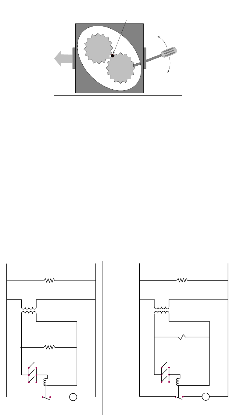
1-27
Sediment Particle
FLOW
Up for reverse
Down for forward
FREEING A SEIZED PUMP
Incorrectly sized or installed paper will also allow food particles and sediment to pass through and
clog the suction tube on the bottom of the filter carriage. Particles large enough to block the suction
tube may indicate that the crumb tray is not being used.
Pan blockage can also occur if shortening is left in the pan and allowed to solidify. The heater strip
on the suction tube is designed to prevent solidification of residual shortening left in the tube. It will
not melt or prevent solidification of shortening in the pan.
Blockage removal can be accomplished by forcing the item out with an auger or drain snake. Never
attempt to use compressed air or other pressurized gases to force out the blockage.
Possible problems with the Power Shower include clogged openings, shortening solidified in the
tubes, missing clean-out plugs, and missing or worn O-rings. Cleaning the unit and replacing
missing plugs and missing or worn O-rings will correct these problems.
The electronics of the Filter Magic and FootPrint III systems are simple and straightforward.
Microswitches, attached to handles for each vat and wired in parallel, provide the 24 VAC required
to activate the pump relay coil when the handles are moved to the ON position. The activated pump
relay coil pulls in the pump motor switch, supplying power to the pump motor.
M
Pump Relay Coil
Micro-switches
Pump Motor Switch
Pump Motor
24 VAC
Line VAC
Filter Magic Simplified Wiring Diagram
Return Line Heater Tapes
Suction Tube (Pan) Heater Tape
M
Pump Relay Coil
Micro-switches
Pump Motor Switch
Pump Motor
Solenoids
(Present in units built after
Jully 1997 only.)
24 VAC
Line VAC
FootPrint III Simplified Wiring Diagram
All Heater Tapes
(Heater Tapes are not present in units
built after July 1997.)

1-28
The oil return line heater tapes in the Filter Magic system are wired directly into the line VAC
source and remain energized as long as the unit is plugged in. The filter pan suction tube heater
tape, however, is wired into the 24 VAC circuit. The suction tube tape is activated only when the
filter pan is positioned all the way to the rear of the cabinet, allowing a pair of “bullet” contactors
mounted on the pan to touch a corresponding pair of contactors mounted on the cabinet frame.
For FootPrint III systems built before August 1997, all heater tapes are wired directly into the line
VAC source. They remain energized as long as the unit is plugged in. In systems built in August
1997 and later, oil return line heater tapes have been eliminated. In these units, the only heater tape
used is on the suction tube and pump. This tape is still wired directly into the line voltage. A pair of
vacuum-breaking solenoids is wired into the 24 VAC circuit.
In units built from August 1997 onward, the oil return system allows oil to drain back to the filter
pan when the filter system is turned off, eliminating the need for most heated oil return components.
For a short time, one-piece, welded oil return manifolds were used. The one-piece manifolds have
been replaced with Dormont stainless steel flexlines and nipples and are no longer available.
PRE-AUGUST 1997 VS CURRENT DESIGN FP-III FILTRATION SYSTEM
Original System Redesigned System
Return lines and manifolds wrapped with silicone
strip heaters and aluminum tape. No heater strips or aluminum tape on return
lines.
Filter base assembly connected to unit with a
black, heated return hose beneath the filter.
Non-heated Teflon hose with a swivel joint con-
nects the filter base assembly to the unit above
the filter.
Filter base assembly equipped with swivel cast-
ers. Filter base assembly has no casters.
Operator-removable filter base assembly. (Filter
base assembly stoplocks in cabinet can be ro-
tated to remove tray.)
Filter base assembly is not removable except by
a qualified service technician. (Filter base as-
sembly stoplocks fitted with a screw and nut to
prevent filter removal.)
Oil remains in return lines when filter system is
turned off.
Oil gravity-drains back to the filter pan when filter
system is turned off, leaving no oil or shortening
in return lines.
Power Shower Sub-System
A solenoid vent valve is mounted on the left end of the front oil return assembly. It prevents
vacuum-lock of the system as oil drains back to the filter pan when the unit is turned off. The
solenoid valve is connected to the square drain sub-system by a clear ⅜” O.D. Teflon tube and
threaded fittings. Stainless steel Dormont flexlines connect the manifolds to the valves. Standard
½” X ½” X 90º black metal street elbows are used to make the connections.
A 22-inch Dormont stainless steel flexline, running above the filter assembly, connects the front oil
return assembly to the rear manifold.
Filter Base Assembly and Pump Sub-System
Casters have not been used on filter base assemblies built since August 1997. When the casters were
eliminated from the filter base assembly, the assembly was redesigned to prevent it from being taken
out of the cabinet without removing a set of machine screws and nuts.
A new Teflon hose with a braided stainless steel covering connects the pump to the rear manifold
and replaces the heated hose running from the pump discharge under the unit to the Power Shower
1-29
plumbing. The new hose is fitted with a 90º swivel at the manifold end and a straight swivel at the
pump end to prevent kinking.
The pump plumbing features a solenoid valve at the pump discharge, a ¼” I.D. Dormont stainless
steel flexline that connects the solenoid valve to the pump inlet fittings, and miscellaneous standard
black metal fittings for connections. This design allows oil to bypass the pump as it drains from the
oil return lines back into the filter pan when the system is turned off. Bypassing the pump expedites
draining of the lines. The pump solenoid leads are connected to Pins 7 and 9 of the upper 9-pin plug
assembly of the filter box.
Filter Wiring Box
The original-design 5-lead cable connecting the filter assembly to the filter wiring box has been
replaced with a new, universal 7-lead cable to accommodate the solenoid mounted on the front
manifold. The two new leads have a separate connector for attachment to the solenoid. When a
filter cable is ordered for either filtration system configuration (original or redesigned), the new
7-wire cable will be sent. The two extra wires and connector will not interfere with the original
filtration system or its operation.
Verifying Solenoid Operation
Proper operation of the 24VAC manifold and pump solenoids can be verified by removing the pump
motor lead from terminal 4 of the pump motor relay in the filter wiring box and then activating the
oil return lever. Proper solenoid operation will be evidenced by an audible “click” or vibration of
both the pump solenoid and the manifold solenoid.
1.7.6 Leakage
Leakage of the frypot is usually due to improperly sealed high limit thermostats, temperature probes,
and drain fittings. When installed or replaced, each of these components must be sealed with
Loctite® PST56765 sealant or equivalent to prevent leakage and torqued to 180 inch-pounds. In
very rare cases, a leak may develop along one of the welded edges of the frypot. When this occurs,
the frypot must be replaced.
If the sides and/or ends of the frypot are coated with oil, the most likely cause is spillage over the top
of the frypot rather than leakage.
The clamps, which hold the drain tube sections together, may loosen over time as the tubes expand
and contract with heating and cooling during use. If the section of drain tube connected to the drain
valve is removed for whatever reason, make sure that its grommet is in good condition and properly
fitted around the nipple of the drain when it is reinstalled. Also, ensure that the drain tube runs
downward from the drain along its whole length and has no low points, where oil may accumulate.
1.7.7 Basket Lift Malfunctions
H50 Series fryers may optionally be equipped with automatic basket lifts to ensure uniform cooking
times. Basket lifts will always come in pairs, although each operates independently of the other.
Depending upon the specific model, date of manufacture, and customer specifications, an H50 fryer
may be equipped with a bell crank style basket lift, or a “modular” basket lift.
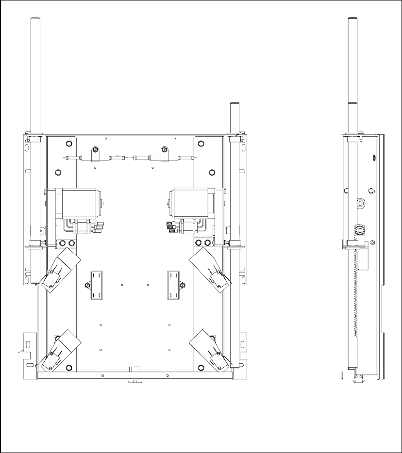
1-30
A modular basket lift (illustrated below) consists of a toothed rod to which the basket lift arm is
attached, a reversible-drive gear motor, and a pair of roller-activated microswitches. The gear motor
engages the teeth in the rod, moving it up or down depending upon the direction of rotation of the
motor. Microswitches at the upper and lower limits of movement stop the motor when the basket is
in the full up or full down position.
Timing circuitry in the controller initiates and stops basket lift operation depending upon the
variables programmed by the operator. When the product button is pressed, the timing circuitry
activates a coil in the basket lift relay to supply power to the lower microswitch. The microswitches
stop the motor at the lift’s upper and lower travel limits and reverse the direction of current flow,
thus reversing the motor direction.
100/120V Modular Basket Lift Assembly
P/N 806-8530SP (TYPICAL)

1-31
A bell crank style basket lift consists of a cam and bell
crank that are connected to the basket lift arm by a flat metal
link. The cam is attached to a drive motor. The motor ro-
tates the cam, thus raising or lowering the lift arm linked to
the bell crank. A roller-activated microswitch is used to limit
travel. When the roller in the microswitch is in contact with
the cam, the motor is energized. As the cam rotates, the mi-
croswitch roller eventually loses contact with the cam and
the circuit is broken, de-energizing the motor.
Timing circuitry in the controller initiates and stops basket
lift operation depending upon the variables programmed by
the operator. When the product button is pressed, the timing
circuitry activates a coil in the basket lift relay to supply
power to the motor. The microswitch stops the motor at the
lift’s lower travel limit and the switch contacts are reversed. At the end of the programmed cooking
time, the timing circuit activates the coil once more and the lift rises until the microswitch again
loses contact with the cam, opening the circuit and stopping the motor.
Problems with either basket lift design can be grouped into three categories:
• Binding/jamming problems
• Motor and gear problems
• Electronics problems
BINDING/JAMMING PROBLEMS
Noisy, jerky or erratic movement of the lifts is usually due to lack of lubrication of the rods and their
bushings. Apply a light coat of Lubriplate® or similar lightweight white grease to the rod and
bushings to correct the problem.
With the modular basket lift, another possible cause of binding is improper positioning of the motor,
which prevents the gear from correctly engaging the teeth in the rod. To correct the problem, loosen
the screws that hold the motor in place and move it forward or backward until the rod has just
enough slack to be rotated slightly.
MOTOR AND GEAR PROBLEMS
With the modular basket lift, the most likely problem to be encountered in this category is erratic
motion of the lift due to a worn drive gear. Failure to keep the lift rod and bushings properly
lubricated will cause unnecessary wear of the gear. The problem is corrected by replacing the worn
gear.
If the lift cycles correctly but fails to remain in the up position (i.e., goes up, but then slowly settles
back down into the frypot), the problem is a failed motor brake. A failed motor brake cannot be
repaired and requires replacement of the motor itself.
Bell crank and cam with basket lift
link shown in down position. Note
microswitch in upper right corner.
1-32
If power is reaching the motor but the motor fails to run, the motor is burned out and must be
replaced.
ELECTRONICS PROBLEMS
Within this category are problems associated with the relays, microswitches, capacitors, resistors,
interface board, wiring, and controls. The most common problem in this category is a lift that
continuously travels up and down. This is usually caused by a microswitch that is out of adjustment.
Troubleshooting the electronics of either type basket lift is simply a process of verifying current
flow through the individual components up to and including the motor. Using a multimeter set to
the 250 VAC range, check the connections on both sides of the component for the presence of the
applied line voltage. The accompanying simplified wiring diagrams identify the components and
wiring connection points.
1.7.8 Interpretation of Digital Controller Lights
Power light on, heat light cycling, trouble light off, and melt light on:
● If fryer oil temperature is below 180ºF (82ºC), the lights indicate the unit is operating
normally.
● If the oil temperature is above 180ºF (82ºC) and the heat light continues to cycle as if in the
melt cycle, this may indicate a defective probe circuit or low incoming 12VAC to the
controller.
Power light on, heat light on, trouble light off, and melt light off:
● If the fryer oil temperature is above 180ºF (82ºC) and below the setpoint temperature, the
lights indicate the unit is operating properly.
● If the oil temperature is above the temperature set on the control knob and the heat light
remains lit, this may indicate a defective probe circuit.
Power light on, heat light off, trouble light on, and melt light off:
● If the fryer oil temperature is below 410ºF (210ºC), the lights indicate one of the following:
a. The probe circuit is defective, or
b. There is a connection problem on pins 2 or 10 on the 15-pin wiring harness.
● If the fryer oil temperature is above 410ºF (210ºC), the lights indicate a run-away heating
circuit.
1.8 Troubleshooting Guide
The troubleshooting guide that follows is intended to assist service technicians in quickly isolating
the probable causes of equipment malfunctions. An additional set of operator troubleshooting guides
is contained in Chapter 6 of the H50 Series Installation and Operation Manual (P/N 819-5000). It is
suggested that service technicians thoroughly familiarize themselves with both sets.

1-33
PROBLEM PROBABLE CAUSES CORRECTIVE ACTION
A. Failed 24V transformer.
Check: LED 3 (24V) is not lit
continuously.
A. If the wiring and connections be-
tween the 24V transformer and
the interface board are intact, re-
place the transformer.
B. Failed interface board.
Check 1: LED 3 (24V) is lit
continuously, but 24 VAC is not
present on the right PWR terminal
(LED 4) (and/or the left PWR
terminal (LED 2), if dual-vat).
Check 2: 24VAC is present on
V1s (or V1D and V2D, if dual
vat).
B. Replace the interface board.
C. Open or failed drain safety switch.
Check: If 24VAC is present on
the gas valve main coil (PV ter-
minal) (on both PV terminals, if
dual-vat), check the connections
and the continuity of the drain
safety switch.
C. Adjust or replace the drain safety
switch as appropriate.
D. Failed high limit.
Check: If 24VAC is present on
the gas valve main coil (PV ter-
minal) (on both PV terminals, if
dual-vat), check the continuity of
the high limit.
D. If the high limit is open, replace.
24V circuit is
suspect.
NOTE: All voltage
measurements must be
made within 4 seconds
of the controller calling
for heat. If the burners
do not fire within 4
seconds, the ignition
modules will lock out
and the controller must
be turned off and then
back on to reset them.
E. Failed ignition module.
Check: 24VAC is not present on
V1S (or V1D and V2D, if dual
vat).
E. If the fuse in the ignition module
is not blown, replace the ignition
module.
Refer also to the diagrams of the 24 Volt Circuit on the following pages.

1-34
LEFT VAT
LED 3 (24V)
IGNITION
MODULE
LED2 (PWR)
PWR
V2D
HIGH
LIMIT
SWITCH
LED1 (GV)
GAS
VALVE
IGNITION
MODULE
PWR
V1S (FV) OR V1D (DV)
HIGH
LIMIT
SWITCH
GAS
VALVE
24V
TRANSFORMER
LED 5 (GV)
J1 PIN 9 J3 PIN 9
FULL OR RIGHT VAT
J3 PIN 8J1 PIN 8
24 VOLT CIRCUIT
With Interface Board 806-3398 or 106-0386 and
Two 807-1006 (FV/DV), 807-2971 (FV/DV), or 807-3365 (DV) Ignition Modules
LED 4 (PWR)
High Voltage
to Ignitor
High Voltage
to Ignitor
FV = Full Vat
DV = Dual Vat
DRAIN
SAFETY
SWITCH
DRAIN
SAFETY
SWITCH
This switch used only with
built-in filtration systems.
Flame Sensor Flame Sensor
Heat Relay
(K2 Fixed)
(K3 Replaceable)
Heat Relay
(K1 Fixed)
(K2 Replaceable)

1-35
24 VOLT CIRCUIT
With Interface Board 806-3398 or 106-0386 and
One 807-3366 (FV) Ignition Module
NOTE: Some units may
be wired in this manner.
IGNITION
MODULE
V1S
PWR (left side)
V2S
LED 5 (GV)
J3 PIN 9
Jumper
LED 3 (24V)
24V
TRANSFORMER
IGNITION
MODULE
PWR (right side)
V1D
LED 5 (GV)
J3 PIN 9
J3 PIN 8
LED 4 (PWR)
HIGH
LIMIT
SWITCH
GAS
VALVE
High Voltage
to Left Ignitor
High Voltage
to Right Ignitor
Left Flame
Sensor
Right Flame
Sensor
DRAIN
SAFETY
SWITCH
This switch used only with
built-in filtration systems.
Heat Relay
(K2 Fixed)
(K3 Replaceable)

1-36
PROBLEM PROBABLE CAUSES CORRECTIVE ACTION
A. Gas valve in non-CE is in OFF
position. A. Place gas valve in ON position.
B. Gas valve in non-CE is in OFF
position. B. Place gas valve in ON position.
C. Improper incoming gas pressure.
Check: Incoming gas pressure is
in accordance with the
appropriate table on Page 1-23 of
this manual.
C. Bring incoming gas pressure into
accordance with the appropriate
table on Page 1-23 of this manual.
Gas supply or gas
valve is suspect.
D. Improper burner manifold gas
pressure.
Check: Burner manifold pressure
is in accordance with the appro-
priate table on Page 1-7 of this
manual.
D. Adjust the gas valve (see proce-
dure 1.4 of this manual) to bring
the burner manifold pressure into
accordance with the appropriate
table on Page 1-7 of this manual.
If the manifold pressure cannot be
properly adjusted, replace the gas
valve.
A. Damaged probe.
Check: While it is still in the fry-
pot, inspect the probe for damage.
A. Replace the probe if the body is
b
ent, dented, or cracked, or if its
wiring is burned, broken, frayed,
or kinked.
Temperature probe
is suspect.
B. Failed probe.
Check 1: Determine the tem-
perature of the oil in the frypot us-
ing a thermometer or pyrometer
placed at the tip of the probe, then
check the for a resistance through
J3 pins 2 and 6 (J1 pins 2 and 6
for the left side of a dual vat) ap-
proximately equal to that given in
the Probe Resistance Chart for the
corresponding temperature.
Check 2: Check for at least 5
megaohms of resistance through
each of the previously tested pins
to ground.
B. If probe does not test OK for both
checks, replace the probe.

1-37
Probe Resistance Chart
For use with H50 Series fryers manufactured with Minco Thermistor probes only.
F OHMS C F OHMS C F OHMS C F OHMS C F OHMS C
60 1059 16 130 1204 54 200 1350 93 270 1493 132 340 1634 171
65 1070 18 135 1216 57 205 1361 96 275 1503 135 345 1644 174
70 1080 21 140 1226 60 210 1371 99 280 1514 138 350 1654 177
75 1091 24 145 1237 63 215 1381 102 285 1524 141 355 1664 179
80 1101 27 150 1247 66 220 1391 104 290 1534 143 360 1674 182
85 1112 29 155 1258 68 225 1402 107 295 1544 146 365 1684 185
90 1122 32 160 1268 71 230 1412 110 300 1554 149 370 1694 188
95 1133 35 165 1278 74 235 1422 113 305 1564 152 375 1704 191
100 1143 38 170 1289 77 240 1432 116 310 1574 154 380 1714 193
105 1154 41 175 1299 79 245 1442 118 315 1584 157 385 1724 196
110 1164 43 180 1309 82 250 1453 121 320 1594 160 390 1734 199
115 1174 46 185 1320 85 255 1463 124 325 1604 163 395 1744 202
120 1185 49 190 1330 88 260 1473 127 330 1614 166 400 1754 204
125 1195 52 195 1340 91 265 1483 129 335 1624 168 405 1764 207
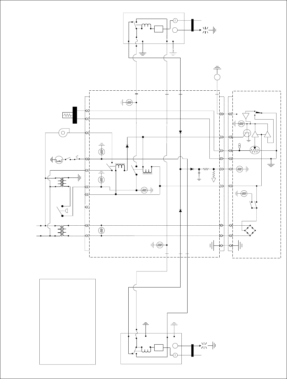
1-38
1.9 Simplified Wiring Diagrams
K2
HEAT
RELAY
K4
BLOWER
RELAY
AIR
OPTIONAL
AIR
SWITCH
BLOWER
HI-LIMIT
12V 24V TEMP
PROBE
24V
LED 3 LED 5
R-GV
R HEAT
LED 4
R
PWR
V1S
ALARM
LED 6
12V
L HEAT
LED 2
L
PWR
ALARM
V2S
POWER
ON/OFF
TROUBLE
HEAT
T
J3
621291185431
J2
11
11
4
4
13
13
14
14
10
10
5
5
3
3
1
1
2
2
GV
RIGHT IGNITION
MODULE
25V+
ALARM
TD
VALVE
GND
BNR
GND
RIGHT
IGNITOR
LEFT IGNITION
MODULE
25V+
ALARM
TD
VALVE
GND
LEFT
IGNITOR
SD
M
LINE VOLTAGE
GND
BNR
DRAIN SAFETY
SWITCH
H50 SERIES — FULL-VAT — JUNE 1996 - JULY 1999
(TWO RELAYS: K2 (HEAT) & K4 (BLOWER) AND TWO IGNITION MODULES)
HV
HV
1/50
A
47K
1K
DRAIN SAFETY SWITCH
ONLY ON MODELS WITH
BUILT-IN FILTRATION
AIR SWITCH
ONLY ON CE AND SOME
EXPORT UNITS
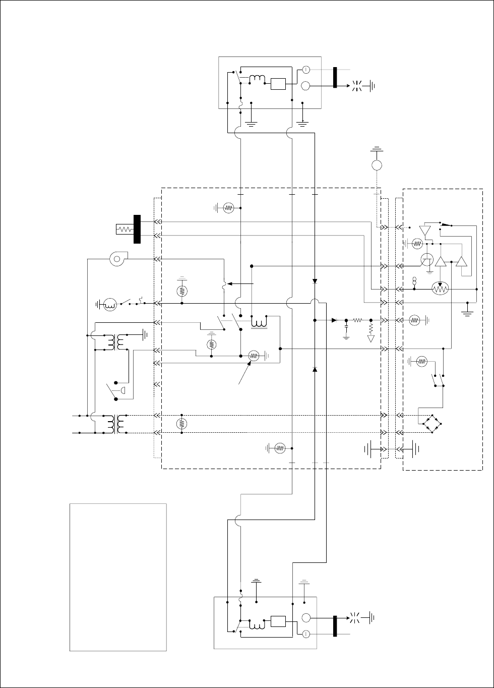
1-39
K3
HEAT &
BLOWER
RELAY
AIR
OPTIONAL
AIR
SWITCH
BLOWER
HI LIMIT
12V 24V
TEMP
PROBE
24V
LED 3
LED 5
R-GV
R HEAT
LED 4
R
PWR
V1S
ALARM
LED 6
12V
L HEAT
LED 2
L
PWR
ALARM
V2S
POWER
ON/OFF
TROUBLE
HEAT
T
J
3
62
1
29
1
185431
J
2
1
1
1
1
4
4
1
3
1
3
1
4
1
4
1
0
1
0
5
5
3
3
1
1
2
2
GV
RIGHT IGNITION
MODULE
ALARM
TD
VALV
E
GND
BNR
GND
RIGHT
IGNITOR
LEFT IGNITION
MODULE
25V+
ALARM
TD
VALVE
GND
LEFT
IGNITOR
S
D
M
LINE VOLTAGE
GND
BNR
DRAIN SAFETY
SWITCH
H50 SERIES— FULL-VAT— BEFORE JUNE 1996 & AFTER JULY 1999
(ONE DUAL FUNCTION HEAT/BLOWER RELAY (K3) AND TWO IGNITION MODULES)
HV
HV
1/50
A
47K
1K
F1
F1 Fuse not
present on
fryers
manufactured
before 6/96
AIR LED not
applicable to fryers
manufactured
before 6/96 25V+
DRAIN SAFETY SWITCH
ONLY ON MODELS WITH
BUILT-IN FILTRATION
AIR SWITCH
ONLY ON CE AND SOME
EXPORT UNITS
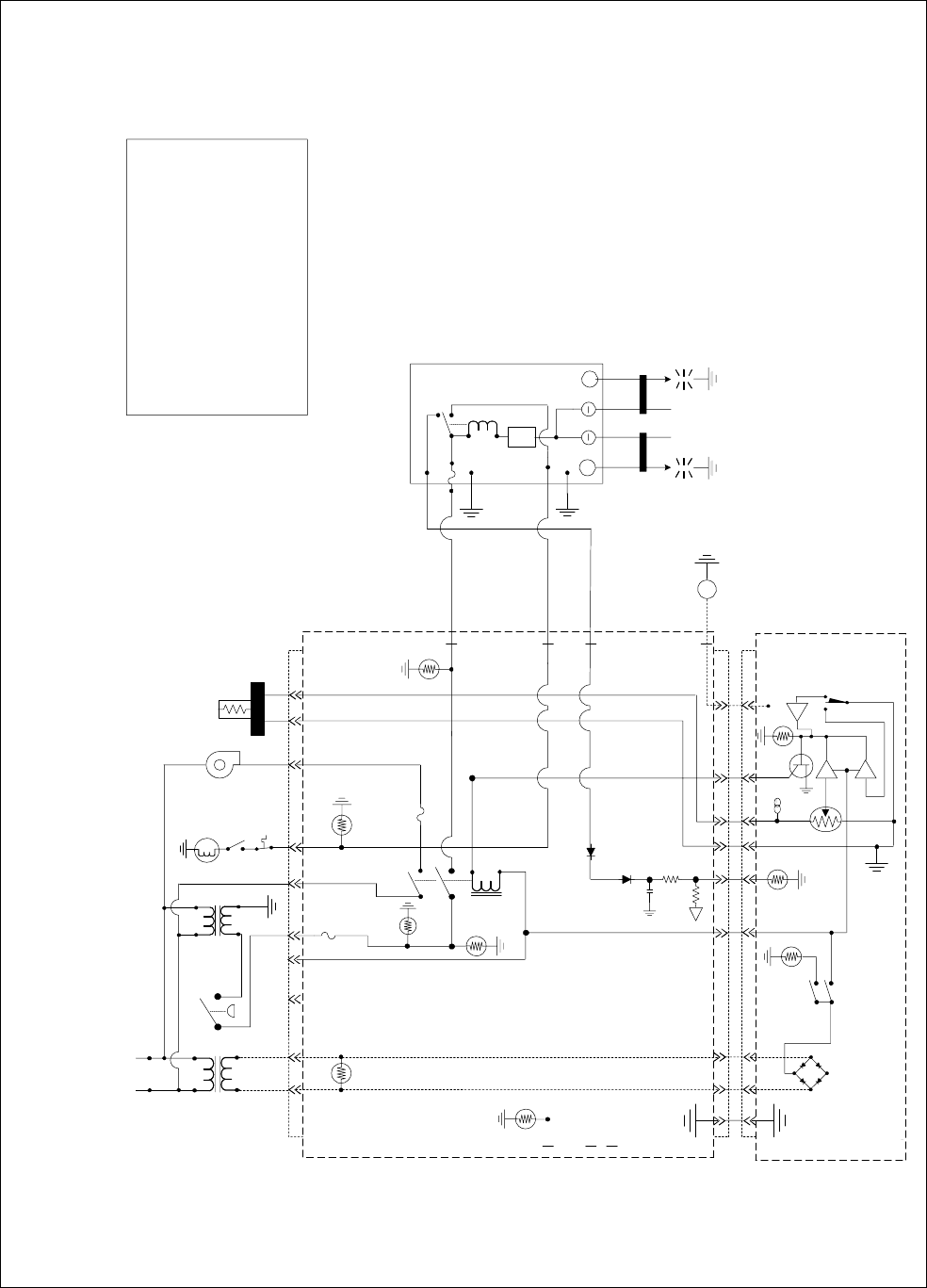
1-40
H50 SERIES— FULL-VAT WITH ONE DUAL-SPARK IGNITION MODULE
(ONE DUAL FUNCTION HEAT/BLOWER RELAY (K3))
LINE VOLTAGE
K3
HEAT &
BLOWER
RELAY
AIR
OPTIONAL
AIR
SWITCH
BLOWER
HI LIMIT
12V 24V TEMP
PROBE
24V
LED 3
LED 5
R-GV
R HEAT
LED 4
R
PWR
V1D
ALARM
LED 6
12V
L HEAT
LED 2
L
PWR
ALARM
V2S
POWER
ON/OFF
TROUBLE
HEAT
T
J3
621291185431
J2
11
11
4
4
13
13
14
14
10
10
5
5
3
3
1
1
2
2
GV
DUAL-SPARK
IGNITION
MODULE
ALARM
TD
VALV
E
GND
BNR
GND
RIGHT
IGNITOR
S
D
M
DRAIN SAFETY
SWITCH
1/50
A
47K
1K
F1
25V+
HV HV
LEFT
IGNITOR
NOTE: SOME UNITS
MANUFACTURED AFTER
AUGUST 2000 ARE
EQUIPPED WITH ONE
DUAL-SPARK IGNITION
MODULE. OTHERS MAY
BE EQUIPPED WITH TWO
SINGLE-SPARK IGNITION
MODULES.
DRAIN SAFETY SWITCH
ONLY ON MODELS WITH
BUILT-IN FILTRATION
AIR SWITCH
ONLY ON CE AND SOME
EXPORT UNITS
F2
FUSE
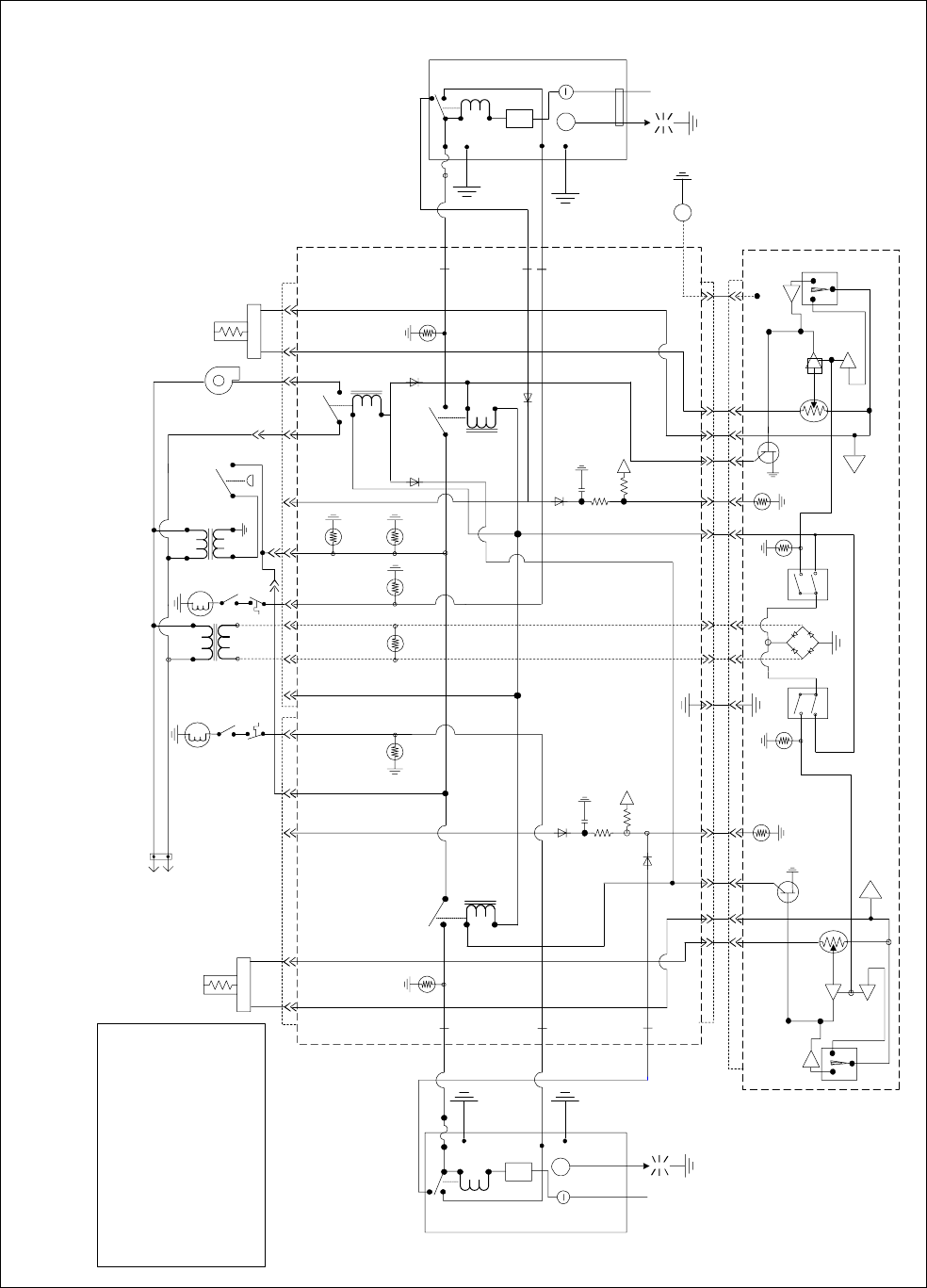
1-41
TD
GND
ALARM
25V+
RIGHT
IGNITOR
VALVE
TEMP
PROBE
BLOWER
24V
HI LIMIT
OPTIONAL
AIR SWITCH
6J3
1148
48
9
9
R HEAT
LED 4
K2 HEAT
RELAY
K4
BLOWER
RELAY
R-GV
LED 5 R
PWR
V1D
ALARM
351041314 11J2
351041314 11
TROUBLE
POWER
HEAT
BNR
GND
GV
AIR
24V
LED 3
RIGHT IGNITION
MODULE
TD
BNR
GND
GND
ALARM
25V+
LEFT
IGNITOR
VALVE
TEMP
PROBE
12V
LINE
VOLTAGE
31598462J1
L-HEAT
LED 2
K1
HEAT
RELAY
12V
LED 6
L-GV
LED 1
L
PWR
V2D
ALARM
15
15
14
14
6
6
12
12
2
2
1
1
POWER
ON/OFF
TROUBLE
LEFT IGNITION
MODULE
12 2
T
M
T
M
A
A
ON/OFF
SD
1K
47K
1/50
1K
47K
1/50
DRAIN
SAFETY
SWITCH
H50 SERIES — DUAL-VAT — JUNE 1996 - JULY 1999
(THREE RELAYS: K1 & K2 (HEAT) AND K4 (BLOWER))
AA
HV HV
DRAIN SAFETY SWITCH
ONLY ON MODELS WITH
BUILT-IN FILTRATION
AIR SWITCH
ONLY ON CE AND SOME
EXPORT UNITS
DRAIN
SAFETY
SWITCH
GV
HI LIMIT

1-42
TD
GND
ALARM
25V+
RIGHT
IGNITOR
VALVE
TEMP
PROBE
BLOWER
24V
OPTIONAL
AIR SWITCH
6J3
1148
48
9
9
R-HEAT
LED 4
K2
HEAT
RELAY
R-GV
LED 5
R
PWR
V1D
ALARM
351041314 11J2
351041314 11
TROUBLE
POWER
HEAT
BNR
GND
AIR
24V
LED 3
RIGHT IGNITION
MODULE
TD
BNR
GND
GND
ALARM
25V+
LEFT
IGNITOR
VALVE
TEMP
PROBE
12V
LINE
VOLTAGE
31598462J1
L-HEAT
LED 2
K1
HEAT
RELAY
12V
LED 6
L-GV
LED 1
L
PWR
V2D
ALARM
15
15
14
14
6
6
12
12
2
2
1
1
POWER
ON/OFF
TROUBLE
LEFT IGNITION
MODULE
12 2
T
M
T
M
A
A
ON/OFF
SD
HV
A
1K
47K
1/50
A
1K
47K
1/50
H
V
F1
F1 Fuse not
applicable to
fryers
manufactured
before 6/96
AIR LED not
present on fryers
manufactured
before 6/96
H50 SERIES — DUAL-VAT — BEFORE JUNE 1996 & AFTER JULY 1999
(TWO DUAL-FUNCTION HEAT/BLOWER RELAYS (K1 & K2)
DRAIN
SAFETY
SWITCH
GV
HI LIMIT
DRAIN
SAFETY
SWITCH
GV
HI LIMIT
DRAIN SAFETY SWITCH
ONLY ON MODELS WITH
BUILT-IN FILTRATION
AIR SWITCH
ONLY ON CE AND SOME
EXPORT UNITS
F2
Fuse
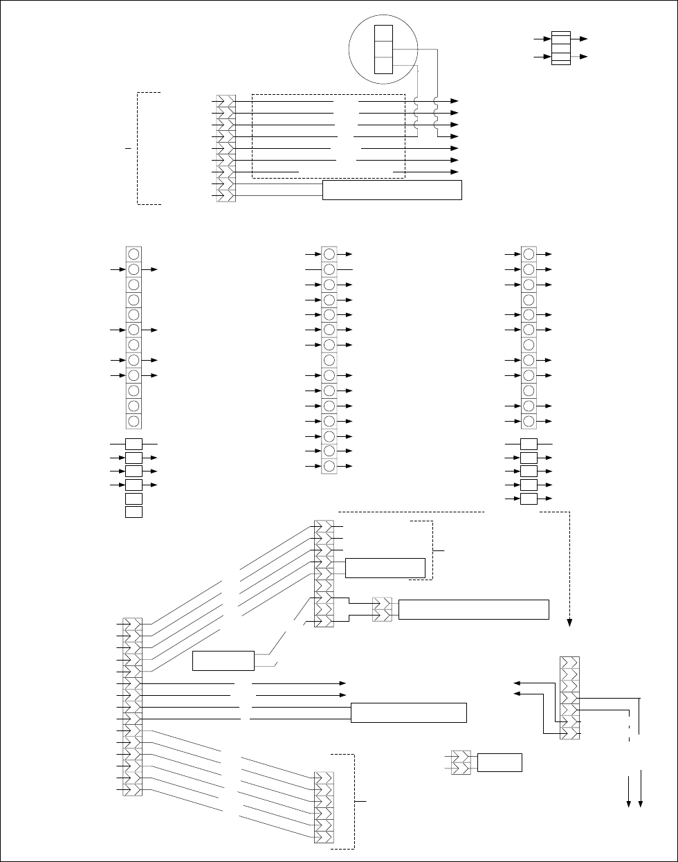
1-43
1.10 Principal Wiring Connections
LEFT PWR VIA K1
GAS VALVE
J1
FROM TO
LEFT VAT
1
2
3
4
5
6
7
8
9
1
0
1
1
1
2
PROBE J2 PIN 14
PROBE J2 PIN 15
C1 PIN 4 (24VAC)
V2D
GROUND GROUND
MODULE VALVE 1 J1 PIN 9
J1 PIN 8 VIA K1 MODULE 25V
DRAIN SWITCH (BIH52 ONLY) J2 PIN 12
GND
V2D
PWR
AD
AS
V2S
J3
RIGHT OR FULL VAT
1
2
3
4
5
6
7
8
9
1
0
1
1
1
2
J2 PIN 1C1 PIN 6 (12VAC)
C1 PIN 4 (24VAC)
V1S OR V1D
GROUNDGROUND
J3 PIN 9MODULE VALVE 1 (DUAL VAT)
J3 PIN 8 VIA K2 MODULE 25V
DRAIN SWITCH (BIH52 ONLY) J2 PIN 10
GND
V1D
PWR
ALR
V1S
J2 PIN 14PROBE
C1 PIN 5 (12VAC) J2 PIN 3
J2 PIN 5 C1 PIN 7
PROBE J2 PIN 13
RIGHT PWR VIA K2
GAS VALVE
C1 PIN 1 (L1) BLOWER VIA K4
C5 PIN 2K4
MODULE VALVE 1 (FULL VAT) J3 PIN 9
FROM TO
J3 PIN 1 CONTROLLER (12VAC)
J2
GROUND
J3 PIN 3 CONTROLLER (12VAC)
GROUND
RIGHT HEAT RELAY (K2)
RELAYS (12VDC) & J3 PIN 5
CONTROLLER
CONTROLLER
LEFT HEAT RELAY (K1)CONTROLLER
K5CONTROLLER
K3CONTROLLER
RIGHT ALARM OUT (FULL VAT)ALR (RIGHT)
SOUND DEVICECONTROLLER
LEFT ALARM OUT (DUAL VAT)AD (LEFT)
J3 PIN 6 CONTROLLER
CONTROLLERJ1 PIN 2 & J3 PIN 2
J1 PIN 6 CONTROLLER
FROM TO
1
2
3
4
5
6
7
8
9
1
0
1
1
1
2
1
3
1
4
1
5
TO T1 & J3 PIN 11
TO J1 PIN 8 & J3 PIN 8
TO J3 PIN 1
TO J3 PIN 3
TO GROUND
TO T2 & C5 PIN 2
TO J3 PIN 5 (12VDC)
LINE VOLTAGE (COM)
LINE VOLTAGE (L1)
LINE VOLTAGE (L1)
GROUND
24VAC
12VAC
12VAC
LINE VOLTAGE (COM)
FROM TRANSFORMER BOX
N.C.
N.O.
COM
AIR SWITCH
(CE AND SOME
EXPORT UNITS)
FILTER PAN SUCTION TUBE HEATER
(BIH52 UNITS ONLY)
C1
T1
T2
(IN COMPONENT BOX)
C2 PIN 1
C2 PINS 3 & 12
LINE VOLTAGE
(L1)
LINE VOLTAGE (COM)
HOOD RELAY
1
2
3
4
5
6
7
8
9
WHITE/BLACK (CE = BROWN)
BLUE
ORANGE
WHITE
GREEN
BLACK
GROUND
LINE VOLTAGE L1
GROUND, JUMPERED TO PIN 11
JUMPERED FROM PIN 4
JUMPERED TO PIN 7
JUMPERED TO PIN 6
FROM T2, JUMPERED TO PIN 9
FROM T1, JUMPERED TO PIN 8
LINE VOLTAGE COM TO OPTIONAL FILTER BOX
C3
C2
TO OIL RETURN SWITCHES OF ADJACENT FRYERS
JUMPERED FROM PIN 3
JUMPERED FROM PIN 5
JUMPERED FROM PIN 1
TO OIL RETURN SWITCHES OF ADJACENT FRYERS
1
2
3
4
5
6
7
8
9
10
11
12
13
14
15
OIL RETURN HEATER
(BIH52 UNITS ONLY)
7P
56C
ORANGE
BLUE
OIL RETURN MANIFOLD SOLENOID VALVE
1
2
1
2
3
4
5
6
7
8
9
OIL RETURN SWITCH
FILTER BOX
PUMP RELAY
ORANGE
BLUE
WHITE
GREEN
BLACK
RED
WHITE & BLACK
1
2
3
4
5
6
C4
TO J1 PIN
10
JUMPERED FROM PIN 2
FROM T2
TO J1 PIN 7
TO J3 PIN
10
TO J3 PIN 7
BLACK
GREEN
WHITE
RED
ORANGE
BLUE
TO OPTIONAL BASKET LIFTS
C5
J3 PIN 12
LINE VOLTAGE (COM) BLOWER
1
2
1
2
3
4
5
6
7
C3
(CE)
OIL RETURN
OIL RETURN
JUMPER TO PIN 4
JUMPER TO PIN 5
PINS 1, 2 & 3
SAME AS NON-CE
CE CONFIGURATION
RED
CABLE TO
FILTER BOX
810-1062
BASKET LIFT
CABLE
807-3695
ON NEWER MODELS
C4 HAS BEEN
CHANGED TO A
12-PIN PLUG SEE PG
1-46

1-44
1.11 WIRING DIAGRAMS - MAIN
FPH150 ONLY (NON-CE)
COMPUTER OR CONTROLLER
TO J2
3C
7C
4C
12V
63
8
9
AIR
12
GND
1
GND
35
PWR
7
V1D
GV
7
52
4
1
11
10
2C
1C
12
69
J2
2
1
64 8
537
2
GV
64 8
AD
11
58
10
7J3
PWR
GND
V1S
ALR
24V
1214
13 9
84
51
12
913
14
PWR
AS
15
84
COMPUTER GROUND (81C)
5C
82C
82C
RIGHT IGNITOR
GND
1
3
2
3
6C
J1 2
1
9C
8C
10C
GND
V2D
PWR
V2S
GND
4
SOUND
LEFT IGN ITOR
DUAL VAT ONLY
14C
DRAIN
NC
NO
C
SWITCH
SAFETY
51C
13C
VALVE
GAS
X
HIGH
LIMIT
PUMP
FILTER
11
12 15
14
13
10
8
9
2
36
5
7
4
1
B
BLK
A
WHITE
WHITE
C2
C3
27C
26C
2
4
1
26C
2
3
YEL/BLK
RED
4
BLK
YEL
27C
6
5
PRPL
BLU
" ON "
1
5
3
28C
X
B
X
18C23C
16C
21C
BLOWER
6
RELAY
N.O.
UNITS ONLY.
OPTIONAL
FALLBACK
CONTROLLER
NOTE: BLOWER SWITCH IS
REQUIRED ON EXPORT
8050439H
22C
NC
NO
4C
BLOWER SWITCH
C
17C
TOGGLE
SWITCH
COM.
12V
TRANS
38C
41C
LINE
LOAD
LINE
LOAD
4C
LINE
LOAD
LOAD
LINE
39C
16C
18C
TEMP
PROBE
SOUND DEVICE
10C
28C
105C
25C 11C
24V
TRANS
OIL
SWITCH
TO NEXT
C
NO
XX
NC RETURN
23C
24V
TRANS
LINE
LOAD
48C
8
12
16 4
54C
OIL RETURN
HEATER
BLK
6
11
10
51
9
15
14
13
3
2
51C
NO
C
NC
110C
SAFETY
DRAIN
SWITCH
TRANSFORMER REAR
EXTENSION
21C
WHITE
LIMIT
HIGH
VALVE
GAS
12C
X
H50/52 SINGLE FP DV NON BL
FRYER
102C

1-45
FPH150 ONLY (CE)
21C
MELT SWITCH
DUAL VAT ONLY
C
SAFETY
51C
NO
NC
SWITCH
DRAIN 14C
VALVE
13C
HIGH LIMIT
GAS
COMPUTER OR CONTROLLER
K1 HEAT
RELAY
RELAY
TROUBLE
LEFT IGNITOR
89C
82C
ON/OFF
SWITCH
2 31 9
MODULE
IGNITION
LEFT
GND 25V
25V GND
10C
BURNER
ALARM
VALVE
7C
6C
8C V2S
9C
ALMD
ALMS
V2D
PWR
LEFT HEAT
L-GV
LED 1
LED 2 K2
510 4
GND
M
T
HEAT
1471113
LED 5
K4
RELAY
R-GV
INTERFACE BOARD
24V
LED 3
FULL POT ONLY
K3 HEAT
RELAY V1S
81C
RIGHT
HEAT
LED 4 PWR
ALM
GND
V1D
EXTENSION
TRANSFORMER REAR
12C
NO
NC
110C
C51C
DRAIN
SWITCH
SAFETY
BLU
BRN
OIL RETURN
HEATER
39C
10
11
12
23C
FRYER
RETURN
TO NEXT
SWITCH
GAS
VALVE
NC
NO C
1
GND
HIGH
LIMIT
1
2
7
4
8
5
3
3
J1
2
69
OIL
(DUAL VAT
ONLY)
SOUND
TEMP
PROBE
24V TRANS
21C
25C
7
9 5
10
11
6
13
14
15
2
3
1
12 816 4
105C
LINE
11C
28C
10C
LOAD
24V TRANS
LINE LOAD
102C
J2 10
12V
LED 6
1
2
3
7
4
6
8
9
5
4
5
1
2
13
14
15
11
12
63
J3
SOUND DEVICE PROBE
TEMP
7
8
10
11
912
23C
16C
TO J2
18C
12V TRANS
LINE
LOAD
28C
RELAY
1
18C
16C
3
24
6
5
RESISTOR
54C
48C
44C
4C
97C
38C
27C
41C
45C
46C
47C
(OPTIONAL)
TO INTERFACE BOARD
WHT
TO BASKET LIFT
82C
RIGHT IGNITOR
89C
RED
BLU
BLK
BURNER
VALVE
ALARM
IGNITION
MODULE
RIGHT
1C 25V
2C GND 25V
3C
4C
GND 5C
7J110
8051150A
GRN/YLW
ORG
POWER BLOCK
TO PIN 10 ON
107J3
LIGHT
BLOWER SWITCH
17C
C
BLOWER
BLK
BLK
" ON "
22C
NC
NO
SWITCH
TOGGLE
COM.
READY
FILTER
20C
43C
73C
5
6
BLK/YLW
97C
PRP
BLU 4
3
21
12
FALLBACK CONTROLLER
N.O.
(OPTIONAL)
WHT
WHT
BLK B
C2
C3
5
3
2
A
11
9
8
615
14
YLW
27C
4
110
7
BLK
RED
26C
PUMP
FILTER
13
CONTACTOR BLOCK
26C
PAN HEATER
27C

1-46
H50 SERIES (NON-CE) OTHER THAN FPH150 AND MANUFACTURED GAS UNITS
(Old Single Spark Ignition Module)
ON SOME
OLDER
UNITS C4
HAD A 6-PIN
PLUG
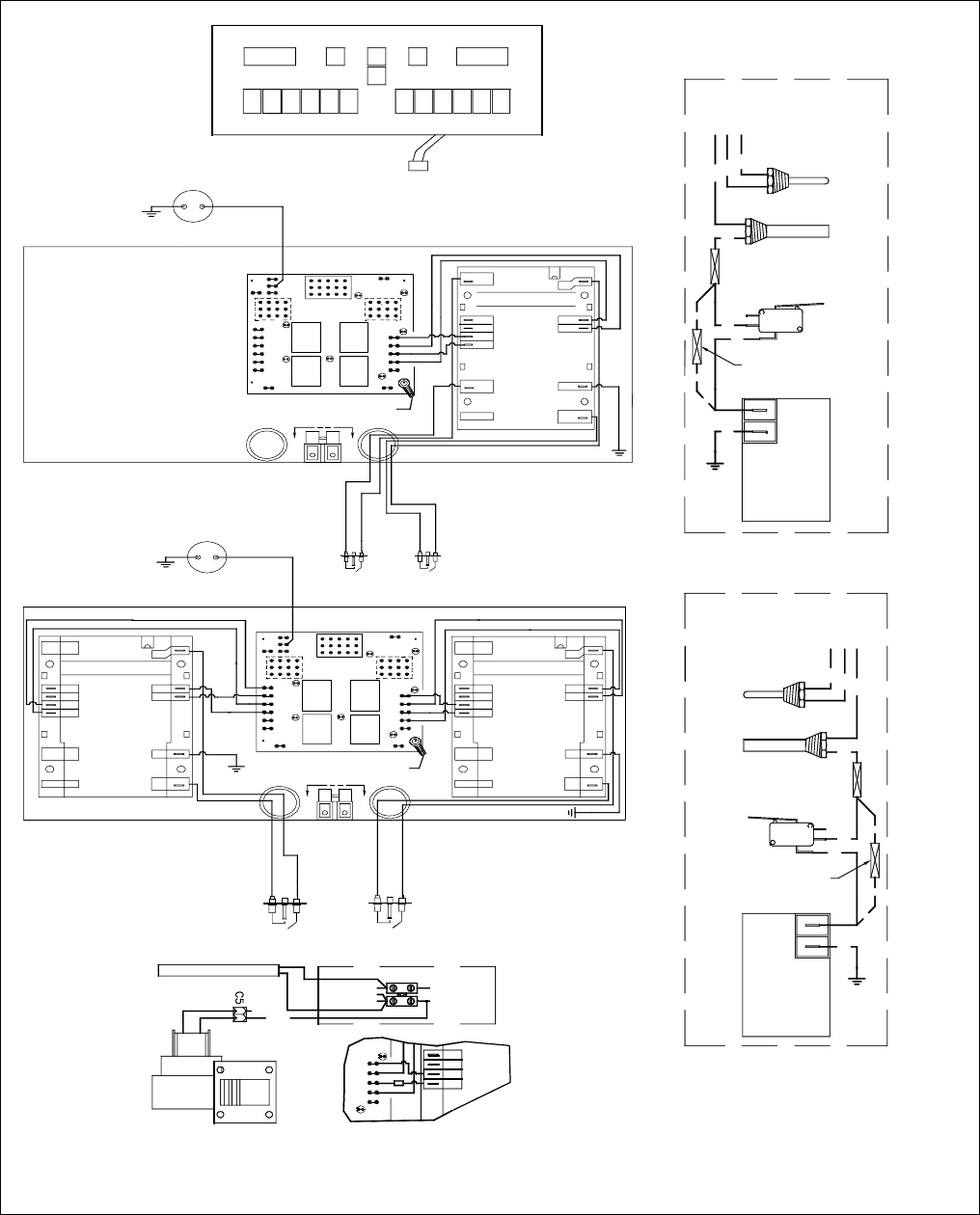
1-47
H50 SERIES (NON-CE) OTHER THAN FPH150 AND MANUFACTURED GAS UNITS
(Newer Dual-Spark Ignition Module)
8051315C
Refer to "PRINCIPAL WIRING CONNECTIONS"
on Page 1-43 for detail of connection points
J1, J2, J3, C2, C3, and C5.
K1
2
COMPUTER GROUND
DETAIL
AA
SENSE 2
ALARM(GND)
VALVE(GND)
24VAC(GND)
24VAC
SPARK 2
SPARK 1
GND
(BURNER)
VALVE
ALARM
SENSE 1
SOUND DEVICE
SOUND DEVICE LEFT IGNITOR RIGHT IGNITOR
FULL VAT
DUAL VAT
RIGHT IGNITOR
LEFT IGNITOR
AA
LEFT
BL
RELAY
RIGHT
BL
RELAY
LEFT DV
HEAT &
BLOWER
RELAY
24V
PWR
V2S
AS
AD
PWR
V2D
GND GV
J1
K2 K3
K4
GND GND
PWR
V1S
ALR
PWR
V1D
GND
GV
J3
AIR
12V
GND
J2
SOUND
1
3
GND
J1
GV
J3
AIR
12V
GND
J2
1
3
GND2
FV OR
RIGHT DV
HEAT &
BLOWER
RELAY
K1
LEFT
BL
RELAY
RIGHT
BL
RELAY
LEFT DV
HEAT &
BLOWER
RELAY
24V
PWR
V2S
AS
AD
PWR
V2D
GND
K2 K3
K4
GND GND
PWR
V1S
ALR
PWR
V1D
GND
SOUND
FV OR
RIGHT DV
HEAT &
BLOWER
RELAY
GV
SENSE 2
ALARM(GND)
VALVE(GND)
24VAC(GND)
24VAC
SPARK 2
SPARK 1
GND
(BURNER)
VALVE
ALARM
SENSE 1
SENSE 2
ALARM(GND)
VALVE(GND)
24VAC(GND)
24VAC
SPARK 2
SPARK 1
GND
(BURNER)
VALVE
ALARM
SENSE 1
COMPUTER GROUND
DETAIL
INSET
HONG KONG
UNITS ONLY
OIL RETURN HEATER FRONT
TO J3 PIN12
WHITE
BLOWER
12
TO C2 PIN1
TO C2 PIN12
TO C2 PIN3
T1 T2
LINE VOLTAGE (L1)
LINE VOLTAGE(COM)
DETAIL A-A
ALARM(GND)
VALVE(GND)
24VAC(GND)
24VAC
FUSE
PWR
PWR
V1D
ALR
V1S
GND
GV
FULL VAT
TO J3 PIN9
TO J3 PIN6
TO J3 PIN2
WHT
RED
BLK
GAS
VALVE
BLK MV
MV
FOR UNITS WITH NO
SAFETY DRAIN SWITCH
ADD IN-LINE SPLICE
BLK
BLK
BLK
TEMP
PROBE
HIGH
LIMIT
NC
NO COM
SAFETY
DRAIN
SWITCH
WHT
RED
BLK
TO J1 PIN2
TO J1 PIN8
TO J1 PIN9
DUAL VAT
TEMP
PROBE
HIGH
LIMIT BLK
BLK
BLK
NC
NO
COM
SAFETY
DRAIN
SWITCH
FOR UNITS WITH NO
SAFETY DRAIN SWITCH
ADD IN-LINE SPLICE
BLK
MV
MV
GAS
VALVE
TO J2
COMPUTER OR CONTROLLER
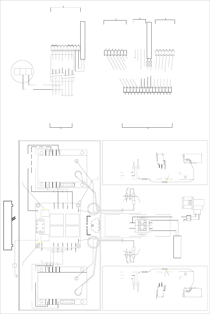
1-48
H50 SERIES (CE) OTHER THAN FPH150 AND MANUFACTURED GAS UNITS
8050526D
OIL RETURN
HEATER FRONT
WHITE
GREEN
WHITE
ORANGE
BLACK
ALARM
VALVE
VALVE
GROUND
(BURNER)
GROUND
25V
25V
TO J1 PIN9
TO J1 PIN6
TO J1 PIN2
DUAL VAT ONLY
TEMP PROBE
RED
WHITE
HI-LIMIT
BLACK
COM
NC
NO
SAFETY DRAIN SWITCH
BLACK
GAS VALVE
14C
BLACK
13C 18C
FOR UNITS WITH NO
SAFETY DRAIN SWITCH
ADD IN-LINE SPLICE
BLACK
BLACK BLACK
BLACK
ADD IN-LINE SPLICE
SAFETY DRAIN SWITCH
FOR UNITS WITH NO
11C12C
BLACK
14C
GAS VALVE
BLACK
SAFETY DRAIN SWITCH
NO
NC
COM
BLACK TO J3 PIN9
HI-LIMIT
TO J3 PIN2
TO J3 PIN6
WHITE
RED
TEMP PROBE
A
BL
RELAY
RELAY
LEFT
DUAL DUAL
OR
FULL
RIGHT
RELAY
RELAY
BL
~
J2 GND
V1S
ALARM
POWER
V1D
GND
BLUE
GREEN
25V
25V
GROUND
ORANGE
(BURNER)
GROUND
VALVE
VALVE
ALARM
SOUND DEVICE
TO J2
COMPUTER OR CONTROLLER
J3 OPPOSITE SIDE
J1 OPPOSITE SIDE
DETAIL
A
COMPUTER GND (81C)
BLACK
WHITE
GREEN
BLUE
GND GND
GND
GND
V2D
PWR
A D
V2S
A S
TO J3 PIN12
DETAIL A-A
LINE VOLTAGE
LINE VOLTAGETO C2 PIN1
TO C2 PIN3
TO C2 PIN12
1
2
3
4
5
6
7
8
9
10
11
12
13
14
15
TO C2 PIN8 & T1
TO C2 PIN11 & GROUND
TO C2 PIN9 & T2
TO C2 PIN6
TO C2 PIN7
TO C2 PIN4
TO C2 PIN5
TO C2 PIN1 & T1
TO C2 PIN3 & T2
TO J1 PIN10
TO C2 PIN2 & GROUND
TO T2
TO J1 PIN7
TO J3 PIN10
TO J3 PIN7
TO ADJACENT FRYERS
TO ADJACENT FRYERS
C2
C3
5
7
6
3
4
1
2
OIL RETURN
LINE VOLTAGE (COM)
LINE VOLTAGE (L1)
GROUND
LINE VOLTAGE (COM)
RIGHT BASKET LIFT
RIGHT BASKET LIFT
LEFT BASKET LIFT
GROUND
LEFT BASKET LIFT
C4
OIL RETURN HOSE HEATER
5
6
4
3
2
1
12
C5
LINE VOLTAGE (COM)
12VAC
12VAC
24VAC
GROUND
LINE VOLTAGE (L1)
8
9
7
6
C1
3
4
5
2
1
HOOD RELAY (H52 ONLY)
LINE VOLTAGE (L1)
LINE VOLTAGE (COM)
TO FILTER
OIL RETURN
TO BASKET LIFT
(H50 MODELS ONLY)
BLOWER
TO J3 PIN11 & T1
TO GROUND
TO T2
TO J1 PIN8 & J3 PIN8
TO J3 PIN3
TO J3 PIN1
TO J3 PIN5
OIL RETURN HEATER REAR
GREEN
BLACK
WHITE
RED
ORANGE
BLUE
BROWN
TO TRANSFORMER BOX
BLACK
GREEN
WHITE
BLUE
ORANGE
ORANGE
BLUE
BLACK
GREEN
WHITE
RED
ORANGE
BLUE
TO COMPONENT BOX TO COMPONENT BOX
WHITE
GREEN
WHITE
N.C.
N.O.
COM
PRESSURE SWITCH
OIL RETURN
TO C3 PIN 4
TO C3 PIN 5
BLUE
ORANGE
TO ADJACENT FRYERS
TO ADJACENT FRYERS
T1 T2
T1 T2 56C
7P
RED
RED
SWITCH
(L1)
(COM)
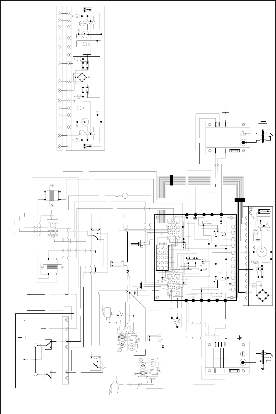
1-49
H50 SERIES MANUFACTURED GAS UNITS
*
(NOTE 2)
*
(NOTE 1)
39C
64C
65C
+
+
9C
8C
12C
TRANSFORMER BOX
40C
12C
(2) CONNECT WIRE 65C AS SHOWN ON NON-FILTER SYSTEMS ONLY.
* NOTE
(1) CONNECT WIRE 64C AS SHOWN ON NON-FILTER SYSTEMS ONLY.
A) CONNECT WIRE 3C TO V1S INSTEAD OF V1D.
LIFT RELAY
RT BSKT
LIFT RELAY
LFT BSKT
95C
97C
96C
94C
(OPTIONAL) (OPTIONAL)
INTERFACE BOARD
SYMBOLICALLY
SHOWN
SPLIT POT COMPUTER OR CONTROLLER
95C
98C
99C
NCNO
C
NC
C
NO
(DV) ONLY
HIGH LIMIT
GAS VALVE
GAS VALVE
LEFT
RIGHT
X
(OPTIONAL)
J2
TROUBLE
T
M
HEAT POWER
ON
ON/OFF ON/OFF
ON
POWER
TROUBLE
M
T
HEAT
4
47
711
1113
1314
1410
105
53
31
12
212
1214
1415
156
69
9
NH
26C27C
43C
44C
46C
45C
OPTIONAL BASKET LIFT
SWITCH
MICRO-
RIGHT
6 PIN CONNECTOR
SWITCH
MICRO-
LEFT
NH
BM
124 3
6
5
BM
NC
C
NO
C
NO NC
34C 35C
33C
32C 31C
30C
29C
SWITCH
SWITCH
12C
85C
86C
1C
TO PIN 8 OF NEXT FRYER (16 PIN TERMINAL BLOCK)
TO PIN 1 OF FILTER (16 PIN TERMINAL BLOCK)
TO PIN 16 OF NEXT FRYER (16 PIN TERMINAL BLOCK)
TO PIN 13 OF FILTER (16 PIN TERMINAL BLOCK)
86C 20C
24C
13
14
15
16
5
6
7
812
11
10
9
4
3
2
1
12V
24V
DRAIN
RIGHT SAFETY
DRAIN
LEFT SAFETY
42C
X
41C
36C
47C
C
NC
NO
NO
NC
C
X
X
22C 13C
23C
24C
X
BLOWER
B
(DV) & (FV)
RIGHT
HIGH LIMIT
LEFT
14C
15C
18C
19C
FOR FULL POT ONLY
(1) CONNECT WIRE 12C TO THE INLINE SPLICE AT THE
RIGHT HIGH LIMIT T'STAT.
(2) OMIT RIGHT GAS VALVE WIRE 13C AND WIRE 22C.
(3) ON LEFT IGNITION MODULE:
A) CONNECT WIRE 8C TO V1S INSTEAD OF V1D.
B) CONNECT WIRE 9C TO ALARM S INSTEAD OF V1D.
(4) ON RIGHT IGNITION MODULE:
(5) OMIT LEFT OPERATION PROBE AND HIGH LIMIT T'STAT.
RIGHT IGNITOR
LEFT IGNITOR
(BURNER)
GND
(GND) ALARM
VALVE
25V
25V
IGNITION
MODULE
(BURNER)
GND
(GND) ALARM
VALVE
25V
25V
IGNITION
MODULE
82C
82C
PROBE
PROBE
RIGHT
LEFT
16C
LEFT RIGHT
12
10
3
1
13
ON/OFF
SWITCH
510 14 134
M
THI LIMIT
TEST SWITCH
SHOWN
11
9
8
7
6
5
4
3
2
1
FULL POT CONTROLLER
SYMBOLICALLY
10C
5C
1
2
3
4
5
6
7
8
9
11
10
12
C
NC
NO
BLOWER SWITCH V1D
GND
PWR
V1S
ALM
V1D
GND
PWR
V1S
ALMD
ALMS
7C
6C
9C
8C
3C
4C
2C 1C
78C
77C
76C
PLAN WIRING DIAGRAM 230/24 V. H50 MANUFACTURED GAS
POWER
HEAT
TROUBLE
2
4
5
6
7
8
9
10
11
12
13
14
15
24V AL PWR GV VR FAN GV PWR AL 12VAIR
12
4
8
5
9
1
8
412 1
5
9
8050344A
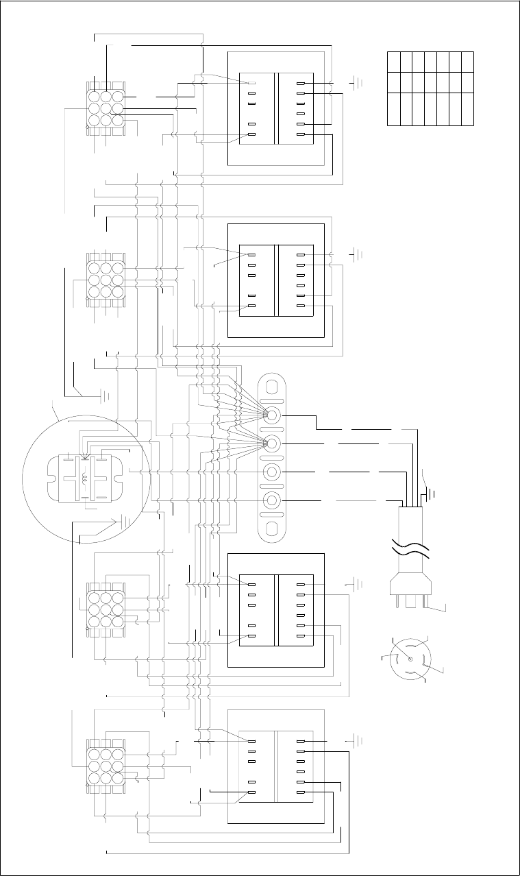
1-50
1.12 WIRING DIAGRAMS – TRANSFORMER BOXES
Non-CE Transformer Boxes
NOTE: USE TERMINALS 7 & 8 FOR 24V OUTPUT.
USE TERMINALS 11 & 12 FOR 12V OUTPUT.
6
712 1011 9 8
21 4 5
12 11 8910 7
521 4 6
COM
NONC
3
45
21
123N
4
7
6
9
5
8
1 32
7 98
4
1
5
2
6
3
120V CONFIGURATION SHOWN
8050500E
1012 11 9 8 7
12 456
7
4
1
89
5
2
6
3
789101112
1 2 4 5 6
1
4
7
32
9
6
5
8
12C
WHT
6C BLUE
40C BLK
1C BLK
8C BLK
19C ORG
9C
WHT
5C ORG
4C RED
41C WHT
13C BLK
22C BLK
WHT
24C
18C BLUE
2C GRN/YLW
14C GRN/YLW
16C RED
17C ORG
25C
BLUE
36C BLK
26C
WHT
15C WHT
3C WHT
23C WHT
20C BLK 21C
WHT
37C BLK 38C WHT
34C
BLK 35C
WHT
31C ORG
52C WHT
33C ORG
30C RED
27C BLK
28C GRN/YLW
43C GRN/YLW
29C WHT
32C
BLUE
42C BLK
45C RED
48C ORG
51C BLK
46C ORG
49C
BLK
39C
WHT
53C
WHT
50C
WHT
44C WHT
42C
BLUE
240 1 6
VOLTS
120
220
230
208
100
61
1
1
1
4
5
2
LINECOM
14
FOR H-52 MODELS ONLY
7C ORG
BLACK
ORANGE
WHITE
GREEN
RED ORG
CONFIGURATION. DO NOT CONNECT TO A STANDARD
120/208V 5WIRE POWER SUPPLY.
STANDARD 5-WIRE 120/208V NEMA L21-20P
CAUTION: THIS PLUG IS NOT BEING USED IN ITS
WHT
TO BODY
GREEN
BLK RED
RELAY
RELAY VAC
NEUTRAL
HOOD
HOOD 120
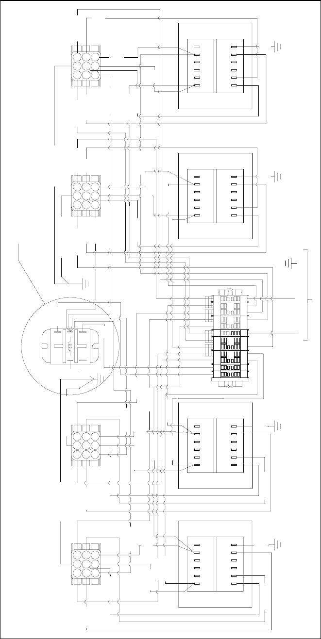
1-51
CE Transformer Boxes
FRYER 4FRYER 3FRYER 2FRYER 1 BLUEBRN
230V/1Ø/50HZ
GRN/YLW
H52 ONLY
3333
NNN33321
52C WHT
7C ORG
BLUE
42C
44C WHT
WHT
50C
WHT
53C
WHT
39C
ORG
49C
46C ORG
51C BLK
48C ORG
45C RED
42C BLK
BLUE
32C
29C WHT
43C GRN/YLW
28C GRN/YLW
27C BLK
30C RED
33C ORG
31C ORG
WHT
35C
BLK
34C
38C WHT
37C BLK
WHT
21C
20C BLK
23C WHT
3C WHT
15C WHT
WHT
26C
36C BLK
BLUE
25C
17C ORG
16C RED
14C GRN/YLW
2C GRN/YLW
18C BLUE
24C
WHT
22C BLK
13C BLK
41C WHT
4C RED
5C ORG
WHT
9C
19C ORG
8C BLK
1C BLK
40C BLK
6C BLUE WHT
12C
USE TERMINALS 11 AND 12 FOR 12V OUTPUT.
NOTE: USE TERMINALS 7 AND 8 FOR 24V OUTPUT.
8
56
9
23
7
4
1
65421
12 11 10 9 8 7
3
6
2
598
1
4
7
65421
7891112 10
8050530D
3
6
2
5
1
48 97
231
8
59
6
7
4
12
54
3
NC NO
COM
641 2 5
710 9 81112
541 2
8911 1012 7
6
8050530D
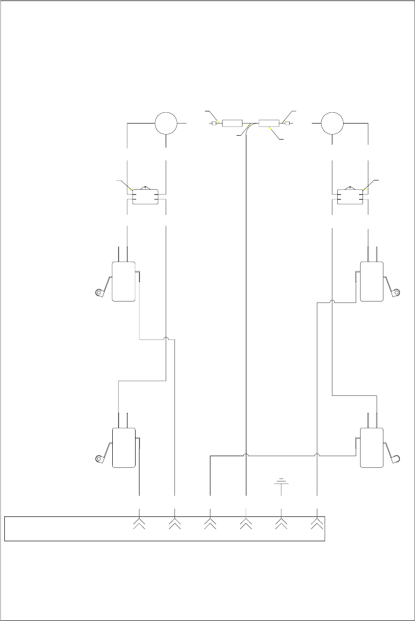
1-52
1.13 WIRING DIAGRAMS – BASKET LIFTS
Modular Basket Lift – 100/120V (NOTE: There is no CE version of this option.)
798101112
mF
12.5
Fm12.5
RESISTOR
SWITCH SWITCH
92C
93C
13W
101C
COM
NO
NC
NC
COM
NO
NC
COM
NO
NC
NO
COM
SWITCH
SWITCH
RED 2
97C
UPPER
BLKBLK
95C
M
BRN 2
RIGHT SIDE
M
BRN 1
98C
UPPER
96C
LEFT SIDE
RED 1
LOWER
12
10C
5 4
29C 61C
3
3C
8050518E
6
32C
LOWER
FROM THE REAR OF THE FRYER
REFERENCES TO LEFT & RIGHT ARE
4C
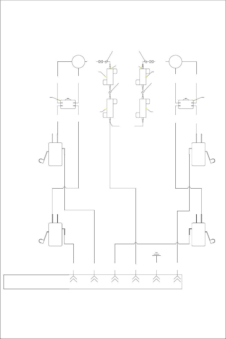
1-53
Modular Basket Lift – 208/250V (NOTE: This diagram is used for both CE and Non-CE applications.)
89101112 7
BLACK
GREEN
WHITE
RED
ORANGE
BLUE
SWITCH
LOWER
SWITCH
LOWER
8C
15C RIGHT SIDE
RED 2
mF12.5
97C
NC
NO
COM
M
BRN 2
BLK
25ohm
101C
(NOT
USED ON
208/220V)
93C
95C
100ohm
100C
LEFT SIDE
BLK
M
25ohm
RED 1
Fm12.5
BRN 1
98C 96C
NO
COM
NC
100ohm
UPPER
SWITCH
NC
COM
NO
3C10C61C29C
8050946B
1234
UPPER
SWITCH
NO
COM
4C32C
NC
56
REFERENCES TO LEFT & RIGHT ARE
FROM THE REAR OF THE FRYER
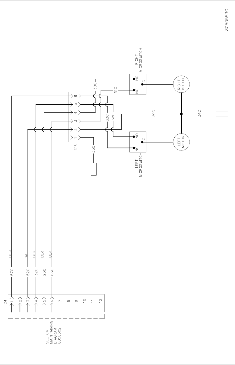
1-54
Bell Crank Basket Lift (NOTE: There is no CE version of this option.)
ON SOME EARLIER UNITS
C4 WAS A 6-PIN PLUG.
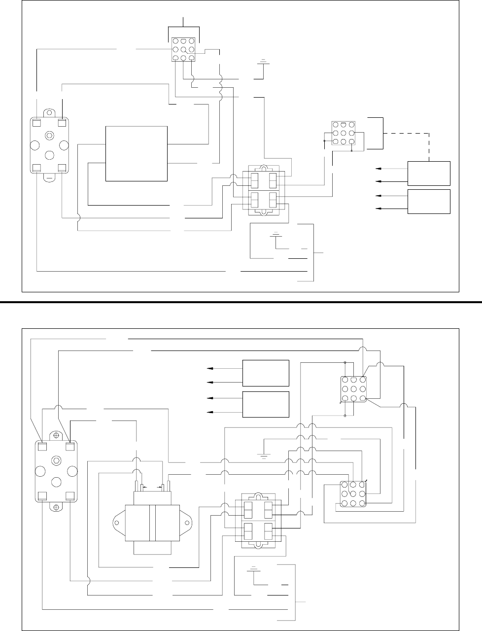
1-55
1.14 WIRING DIAGRAMS – FILTER BOXES
FootPrint III Prior to August 1997 (NOTE: This diagram is used for both CE & Non-CE applications.)
123
456
789
TO PUMP MOTOR
24
13
45C
10C
52C
11C
8C
41C
30C
12C32C
26C
13C
9C
RED
RED
RED
LOAD
LINE
T2
T1
1
4
7
23
5
8
6
9
62C
92C PUMP
HEATER
LINE
HEATER
(OPTIONAL)
BLACK
WHITE
WHITE
BLACK
TO PIN 4
TO PIN 6
TO PIN 1
TO PIN 3
8050832A
24V
TRANSFORMER
PUMP RELAY
TO FRYER
FootPrint III August 1997 and Later (NOTE: This diagram is used for both CE & Non-CE applications.)
147
258
369
TO PUMP MOTOR
24
13
45C
10C
52C 14C
8C
41C
30C
12C
32C
26C
13C
9C
RED
RED
T2
T1
9
8
7
63
5
4
2
1
62C
92C
PUMP
HEATER
PUMP
SOLENOID
TO PIN 1
TO PIN 3
TO PIN 7
TO PIN 9
LINE
24V/50VA
T-4
11C
108C
27C
51C
8050902C
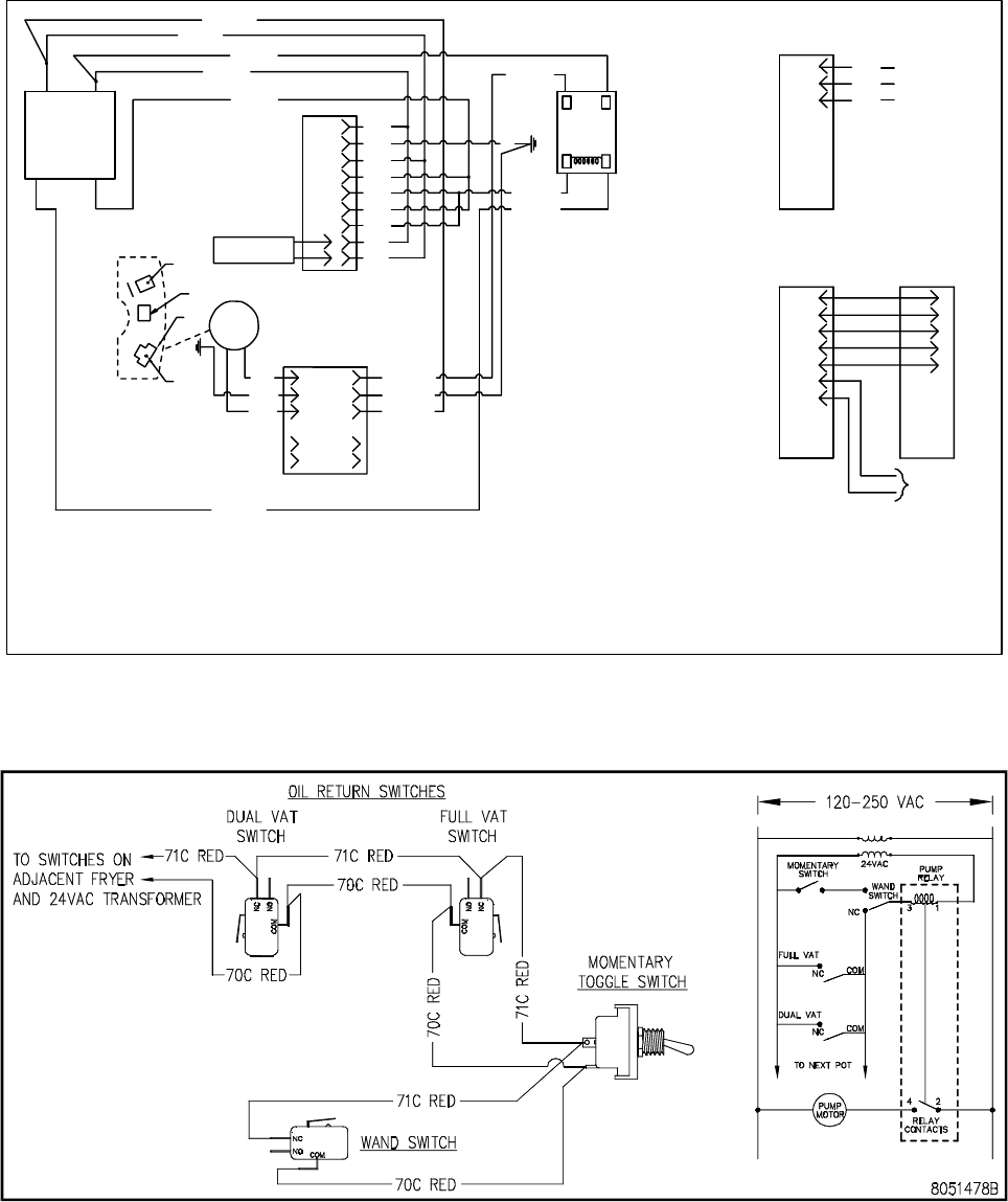
1-56
Filter Magic II (NOTE: This diagram is used for both CE and Non-CE applications.)
1
2
3
4
5
6
7
8
9
C3
6
5
4
3
C6
2
1
PUMP
MOTOR
LINE VOLTAGE
TRANSFORMER
LOAD
24VAC
RELAY
NO
2 4
13
25C BLU
23C BLK
11C BLK
7P WHT
29C WHT
27C ORG
21C ORG
BLK
GRN
WHT
BLU
ORG
BLU
BLK
WHT
ORG
22C BLK
22C BLK
2C GRN
29C WHT
L1
L2
4
38
5
LINE
LINE
2C
21C ORG
BLK
GRN
WHT
9
WHT
3
6
8
7
5
4
GRN
BLK
2
1
N
H
G
EXTERNAL
POWER
SOURCE
NON- DIRECT OPTION
8050503E
HEATER TAPE
FROM PUMP
4
C3
15
5C2
FRYER
ADJACENT
TO
1
3
2
1
3
2
PIN
6
7
5
4
7
6
8
8
9
C3
807-2016
FILTER MAGIC
MAIN POWER CABLE
1.15 WIRING DIAGRAMS – OIL RETURN
Oil Return/Disposal Wand Wiring (Japan/Lotteria)
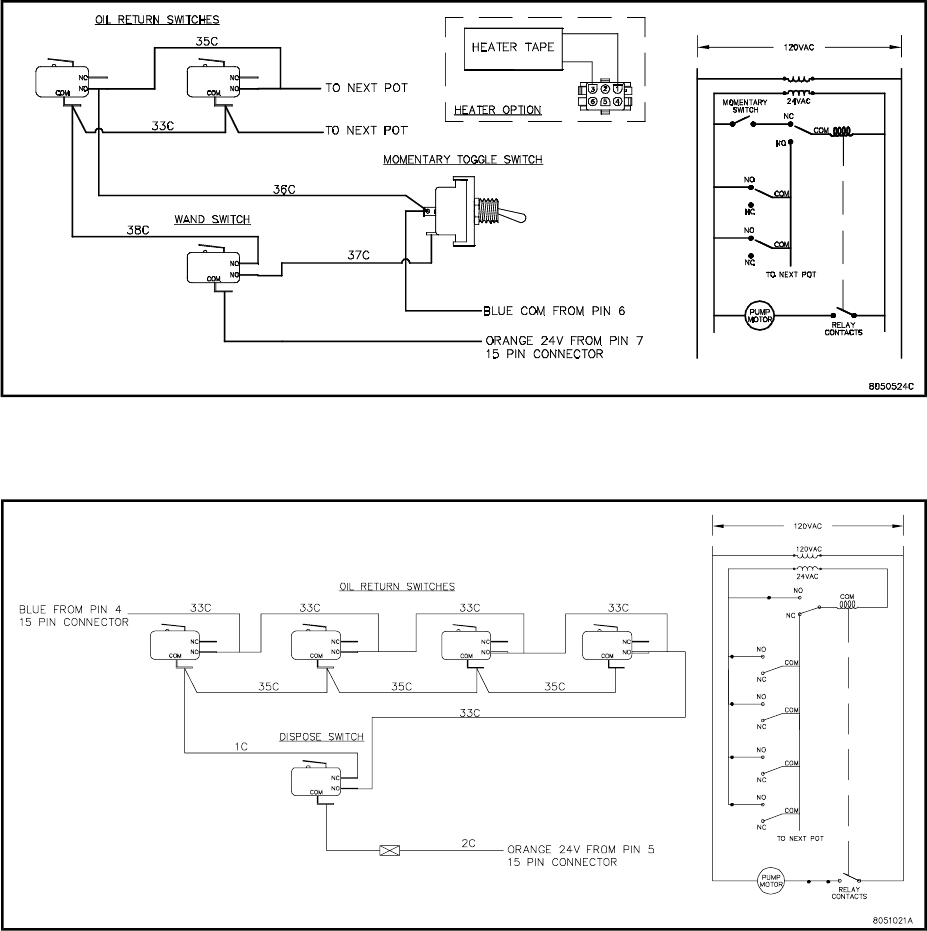
1-57
Oil Return/Wand Wiring (Japan)
Oil Return/Disposal Wand Wiring (Sonic)
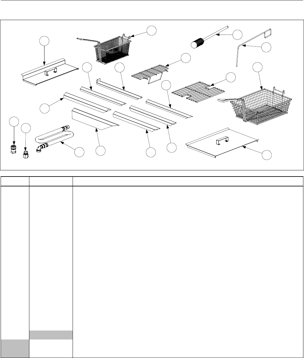
2-1
H50 SERIES GAS FRYERS
CHAPTER 2: PARTS LIST
2.1 Accessories
1
2
3
4
5
6
7
10
8
9
11
12
13
14
15
16
17
18
ITEM PART # COMPONENT
1 803-0271 Basket, Twin
2 803-0099 Basket, Full (cannot be used with basket lifts)
3 803-0133 Basket Support Rack, Dual Vat
4 803-0132 Basket Support Rack, Full Vat
* 803-0136 Basket Support Screen, Full Vat (screen w/handle used in place of Item 4)
5 806-3232 Cover, Frypot, Dual Vat
6 806-5518 Cover, Frypot, Full Vat
* 826-0993SP Handle Kit, Frypot Cover (includes handle and screws)
7 823-1885 Connecting Strip w/back plate (Burger King only)
8 910-4617 Connecting Strip (blunt point, ½” sides, 20.70” long) –Applebee’s Fryer to Filter
9 910-2285 Connecting Strip (blunt point, 1” sides, 20.80” long)- B.K. Wide
10 910-7515 Connecting Strip (sharp point, ½” sides, 21.73” long)- B.K. Dump Station to
Fryer, Also Applebee’s
11 910-7443 Connecting Strip (sharp point, 1” sides, 21.73” long)
12 910-7515 Connecting Strip (sharp point, 1” sides, 21.84” long)
13 910-2572 Connecting Strip (sharp point, 3” sides, 21.84” long)
14 Gas Line, 1-Inch Dormont Flexible (includes Items 15 and 16)
806-1698 36-Inch (for gas line only (w/o Items 15 and 16), use 810-0088)
806-1699 42-Inch (for gas line only (w/o Items 15 and 16), use 810-0085)
Continued on the following page

2-2
ITEM PART # COMPONENT
15 810-0074 Quick-Disconnect Fitting, 1-Inch Male
16 810-0073 Quick-Disconnect Fitting, 1-Inch Female
17 803-0209 Brush, Frypot Cleaning
18 803-0197 Fryer’s Friend 27” (Clean-out Rod)
* 910-3557 Flue Deflector
* 810-1306 Valve, Manual Gas Shut Off ½”
* 810-1307 Valve, Manual Gas Shut Off ¾”
* Not illustrated.
NOTE: Sediment Trays: 803-0103 (Full-Vat), 803-0107 (Left Dual-Vat), and 803-0108 (Right Dual-Vat)

2-3
2.2 Basket Lift Assemblies and Component Parts
2.2.1 Bell Crank Basket Lifts
23
36
12
27
37
24
29
30
28
20
33
511
5
1
6
31
32
17
14 15 25
16
16 15
719 21
17 4
10 326
34
23
18
2
11
13
35
22
24
9

2-4
ITEM PART # COMPONENT
1Gear Motor, Basket Lift
807-0107 120VAC
807-0108 240VAC
2 807-0124 Bushing, Plastic
3 807-0240 Microswitch
4 826-1680 Clamp, Plastic Wire (Pkg. of 8)
5 826-1358 Nut, 6-32 Hex (Pkg. of 25)
6 809-0050 Nut, 2-32 Hex
7 809-0063 Nut, Jam ⅜-16 Hex
8 809-0076 Nut, ¼-20 x ¾ Expansion
9 809-0082 Ring, Truarc Retaining
10 809-0097 Screw, 6-32 X 1-inch Slotted Truss Head
11 809-0113 Screw, 2-32 X 1½-inch Slotted Truss Head- Req 2 + 2 (809-0503 Motor Mounts)
12 809-0127 Screw, ¼-20 X ½-inch Slotted Round Head
13 826-1370 Screw, ¼-20 X 1¼-inch Slotted Round Head (Pkg. of 10)
14 809-0155 Leveling Screw
15 809-0196 Washer, ⅜-inch Steel Flat
16 826-1381 Washer, Nylon (Package of 10 each 809-0203)
17 809-0360 Screw, 2-32 X ⅜-inch Slotted Hex Washer Head
18 826-1374 Screw, 10 X ½-inch Hex Washer Head (Pkg. of 25)
19 809-0480 Setscrew, ¼-28 X ⅝-inch Hex Socket Head
20 810-0045 Bushing, Plastic
21 810-0052 Bellcrank and Cam
22 810-0170 Pin, Connecting
23 810-0172 Plug, ⅝-inch Hole S/S
24 810-0192 Rod, Basket Lift
25 810-0220 Spacer, Tubular
26 812-0138 Insulation, Paper (Fishpaper)
27 813-0035 Bushing, Bronze
28 823-1419 Box, Electrical Wiring
29 900-4110 Angle, Bearing Support
30 910-0119 Cover, Electrical Wiring Box
31 910-3177 Panel, Stainless Steel Rear Access (for mild steel, use 900-3177)
32 910-3783 Cover, Stainless Steel Rear Cabinet (for mild steel, use 900-3783)
33 910-9361 Housing, Basket Lift Stainless Steel (for mild steel, use 900-9361)
34 920-3233 Plate, Basket Lift Motor Mounting
35 920-6076 Link, Basket Lift
36 823-06931 Basket Lift Arm, Left
37 823-06932 Basket Lift Arm, Right
810-0172 Plug Button SS ⅝” Hole
* 806-2078 Wiring Harness, Basket Lift Power (6-pin male w/5 wires)
* 806-2079SP Wiring Harness, Basket Lift Motor (6-pin female w/7 wires)
* 806-7019SP Wiring Harness, Non-Modular Basket Lift (6-pin male & female w/5 wires)
* 807-2000 Wiring Harness, H50 B/L Connecting (15-pin male & female w/13 wires)
* 807-3695 Cable, H50 Basket Lift (15-pin male & 12-pin male w/6 wires) C2 to C4
* 807-2033 Cable, H50 Basket Lift (15-pin male & 6-pin male w/ 6 wires ) Older cable
* Not illustrated.
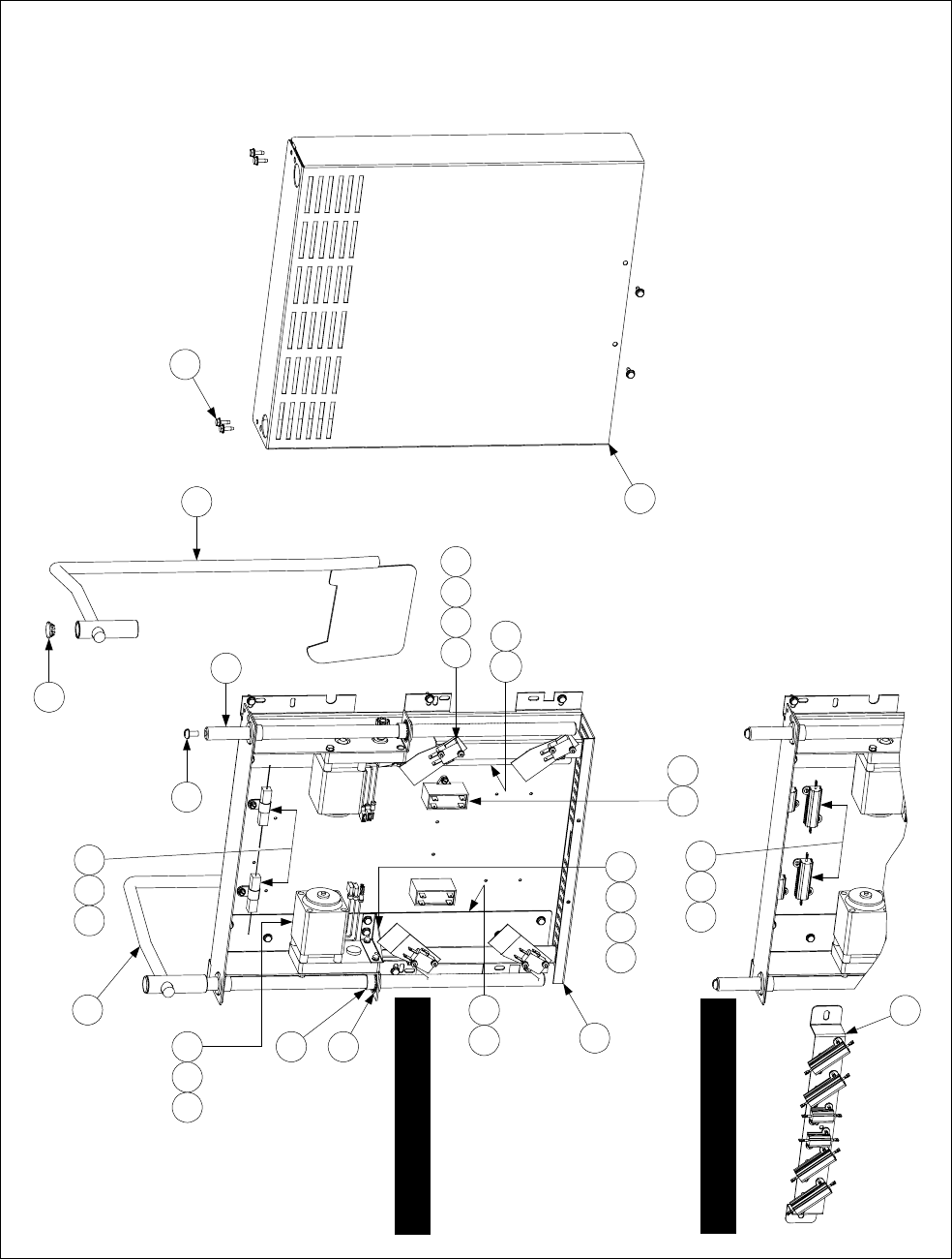
2-5
2.2.2 Modular Basket Lifts
NOTES:
1. Assemblies 106-1807SP (100-120V) and 106-1810SP (208-250V) do not
include Items 8, 16, 24, 25, and 26. These items must be ordered separately.
2. For 100-120V units, each individual resistor (807-2661) may be replaced or
the entire reistor assembly (806-8530SP) may be replaced.
3. For 208-250V units, the entire resistor assembly (106-2771 or 806-9185) must
be replaced.
4. Wiring has been omitted for clarity.
24
14
100-120V Configuration
208-250V Configuration
2114117
12105
20135
26
8
17
25
16
313
410 12 18
2314
14 22
1
6
19
1592
5
(After 10/02)
(Before 11/02)

2-6
ITEM PART # COMPONENT
1Mount, Modular Basket Lift**
200-2942 For use on units with 12-pin connectors
900-7655 For use on units with 6-pin connectors
2 806-5964SP Motor Assembly, Modular Basket Lift
810-1013 Gear, Modular Basket Lift (809-0504 Set Screw, 6-32 x .185)
3 807-2513 Capacitor, 12.5 µFarad, 250VAC Motor Run
4 807-2572 Microswitch
5Resistor Assembly
806-8530SP 100-120V Modular Basket Lift (see Note 2 in illustration) 807-2661 Resistor only
CE 106-2771 208-250V Modular Basket Lift (before 11/02 use 806-9185; see Note 3)
6 809-0082 Ring, Truarc Retaining
7 826-1361 Screw, 2-32 X 1-inch Slotted Truss Head (Pkg. of 25)
8 809-0127 Screw, ¼-20 X ½-inch Slotted Round Head
9 809-0186 Lock Washer w/External Teeth, #8
10 826-1366 Nut, 4-40 Hex Keps (Pkg. of 25)
11 809-0247 Nut, 2-32 Hex Keps
12 826-1359 Screw, 4-40 X ¾-inch Slotted Round Head (Pkg. of 25)
13 826-1371 Screw, #8 X ½-inch Hex Head Drill Point (Pkg. of 25)
14 826-1374 Screw, #10 X ½-inch Hex Head (Pkg. of 25)
15 809-0503 Screw, 2-32 X ½-inch Hex Head
16 810-0172 Plug, ⅝-inch Stainless Steel Hole
17 810-1012 Rod, Modular Basket Lift
18 812-0442 Insulation, Microswitch
19 813-0035 Bushing, Bronze, .640” ID
20 816-0033 Tie Wrap, Screw Mount
21 900-5529 Gusset, Modular Basket Lift Motor
22 901-8499 Chassis, Modular Basket Lift, Left
23 902-8499 Chassis, Modular Basket Lift, Right
24 910-4776 Cover, S/S Modular Basket Lift (for CRS cover use 900-4776)
826-1991 Cover, Kit S/S Modular Basket Lift with screws
25 823-06931 Arm Rod Assembly, Left Basket Lift
26 823-06932 Arm Rod Assembly, Right Basket Lift
*Connector, Panel Mount**
807-0159 12-pin
807-0158 6-pin
Wire Assemblies**
* 806-9014SP For 100-120V Modular Basket Lift w/6-Pin Connector
* 806-8555SP For 202-250V Modular Basket Lift w/6-Pin Connector
* 106-1822SP For 100-120V Modular Basket Lift w/12-Pin Connector
* 106-1804SP For 202-250V Modular Basket Lift w/12-Pin Connector
Basket Lift Assemblies (see Note 1 in illustration)
* 106-1807SP 100-120V w/o Relay
* 106-1810SP 202-250V w/o Relay
** Not illustrated.
** Basket lift assemblies manufactured prior to February 2002 have 6-pin connectors; those manufactured February
2002 and later have 12-pin connectors. Verify the type of connector in use before ordering wiring assemblies or mounts.
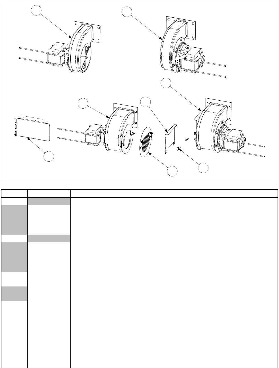
2-7
2.3 Blower Assemblies and Associated Components
12
3
4
5
6
7
8
ITEM PART # COMPONENT
1Blower, Left (with 1.54-inch (3.91 cm) narrow housing)
106-2996SP 100V, 50/60 Hz
106-2994SP 115V, 50/60 Hz
806-5841SP 230V, 50 Hz
106-2995SP 240V, 50 Hz
2Blower, Right (with 1.54-inch (3.91 cm) narrow housing)
806-4697SP 100V, 50/60 Hz
106-2997SP 115V, 50/60 Hz
807-7060SP 230V, 50 Hz
106-2998SP 240V, 50 Hz
3 106-3000SP Blower, Assembly Left, 230V, 50/60 Hz (with 2.2-inch (7.11 cm) wide hous-
ing) non-CE and CE
106-3002SP Blower, Assembly Left, 24V, 50/60 Hz (with 2.2-inch (7.11 cm) wide housing)
non-CE and CE
4 106-3001SP Blower, Assembly, Right 230V, 50 Hz (with 2.2-inch (7.11 cm) wide housing)
CE and non-CE
106-3003SP Blower, Assembly, Right 24V, 50 Hz (with 2.2-inch (7.11 cm) wide housing)
CE and non-CE
106-3000SP Blower Assembly, Left 230V, 50 Hz (CE)
5 806-9689 Finger Guard/Air Flow Inhibitor Adapter (CE)
6 900-8699 Air Flow Inhibitor (CE)
7 826-1382 Wingnut, 2-32 (Pkg. of 10)
8 826-1426 Shield, MH52 Blower Motor
Continued on the following page.

2-8
ITEM PART # COMPONENT
* 816-0554 Cover, Molded Plastic Blower Motor (fits left- or right-hand blowers)
* 809-0938 Screw, 10-32 X ⅝ Philips Truss Head (secures Blower Motor Cover to motor)
* 826-1383 Washer, ¼-inch Flat (for mounting blower to plenum) (Pkg. of 5)
* 826-1372 Nut, ¼-20 Hex (for mounting blowers to plenum) (Pkg. of 10)
* KIT-0155SP High Altitude Blower Kit (required above 5000 Ft, 1525 M)
* Not illustrated.
NOTES: Items 5, 6, and 7 are components of Items 3 and 4. In CE units, they replace the rotating air shut-
ter that is standard on 230V Blowers 106-3000SP and 106-3001SP (Items 3 and 4).
Blower Motor Cover P/N 816-0054 and Screw P/N 809-0938 are components of Items 1 through 4.
For Full Vat units, use Blower Assembly 106-2994SP (Non-CE) or 106-3000SP (CE). (Left Assembly.)
Some earlier CE units were built with blowers having housings 1.54 inches (3.91 cm) wide. Current
production CE-units are built with blowers having housings 2.71 inches (6.88 cm) wide. When order-
ing replacements for CE units, the width of the blower housing must be verified to ensure the correct
blower is provided.
CE units built before June 1999 were equipped with a blower shield that completely covered the
blower assemblies. This shield is no longer required and may be removed. The component parts of
the shield are no longer available for replacement.
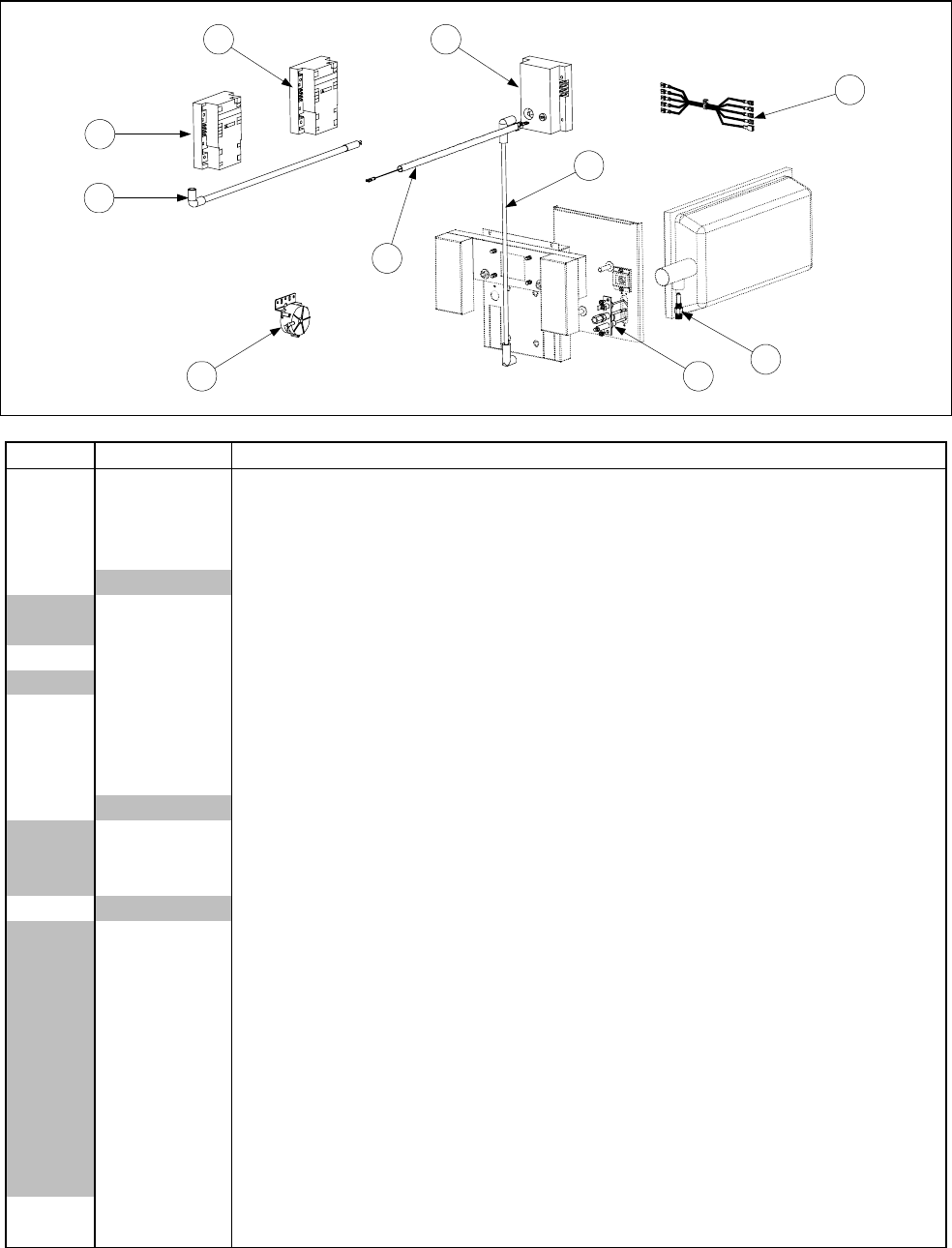
2-9
2.4 Burner Ignition System Components and Associated Hardware
2
3
5
8
1
4
6
7
9
10
ITEM PART # COMPONENT
1 See Pg 2-19 Ignition Module, Full and Dual Vat (original design, with fuse) 807-0910 Fuse
2 See Pg 2-19 Ignition Module, Full Vat (new design, without fuse)
* 826-1346 Spacer (Pkg. of 10)
3 See Pg. 2-19 Ignition Module, Dual Vat (new design, without fuse)
4Ignition Cable
807-1878 19-inches long (with two 90º connectors, used with Item 1 only)
807-1200 27-inches long (with one 90º connector and one straight connector)
5 826-1721 Ignition Cable w/ Rajah (with one 90º connector, used with Items 2 and 3 only)
807-3483 Cable, Ignition 21” (807-3484 Rajah Connector Only)
6 806-6085SP Wire Assembly, Flame Sensor
7 806-6084SP Wiring Assembly, Ignition Module
8 807-2263 Switch, Air Pressure (use 807-2262 in units with 100VAC power supply)
* KIT1428 CE Export Air Switch Kit
9Ignitor and Gasket Kit (816-0059 Gasket Only)
826-0981 Natural Gas (G20, G25)
826-0982 Propane/Butane (G30, G31)
826-1002 Manufactured Gas
10 Orifice
812-1137 1.95 mm Propane/Butane (G30, G31) (0-4999 Ft, 0-1524 M) (CE)
810-1221 2.00 mm Propane/Butane (0-4999 Ft, 0-1524 M) (Japan only)
810-0386 2.10 mm Propane/Butane (0-4999 Ft, 0-1524 M)
810-0413 2.16 mm Propane/Butane (G30, G31) (5000-6999 Ft, 1525-2133 M)
812-1028 2.20 mm Propane/Butane (G30, G31) (7000-10,999 Ft, 2134-3352 M)
812-1134 3.10 mm Natural Gas (G20, G25) (0-4999 Ft, 0-1524 M) (Japan only)
810-0403 3.40 mm Natural Gas (G20, G25) (0-4999 Ft, 0-1524 M)
810-0437 3.60 mm Natural Gas (G20, G25) (5000-6999 Ft, 1525-2133 M)
812-1144 3.65 mm Natural Gas (G20, G25) (7000-8999 Ft, 2134-2743 M)
812-1145 3.70 mm Natural Gas (G20, G25) (9000-10,999 Ft, 2744-3352 M)
810-0642 5.95 mm Manufactured Gas (0-4999 Ft, 0-1524 M)
* 826-1196 Conversion Kit, Natural Gas (G20, G25) to Propane/Butane (G30, G31)
* 826-1197 Conversion Kit, Propane/Butane (G30, G31) to Natural Gas (G20, G25)
* Not illustrated.
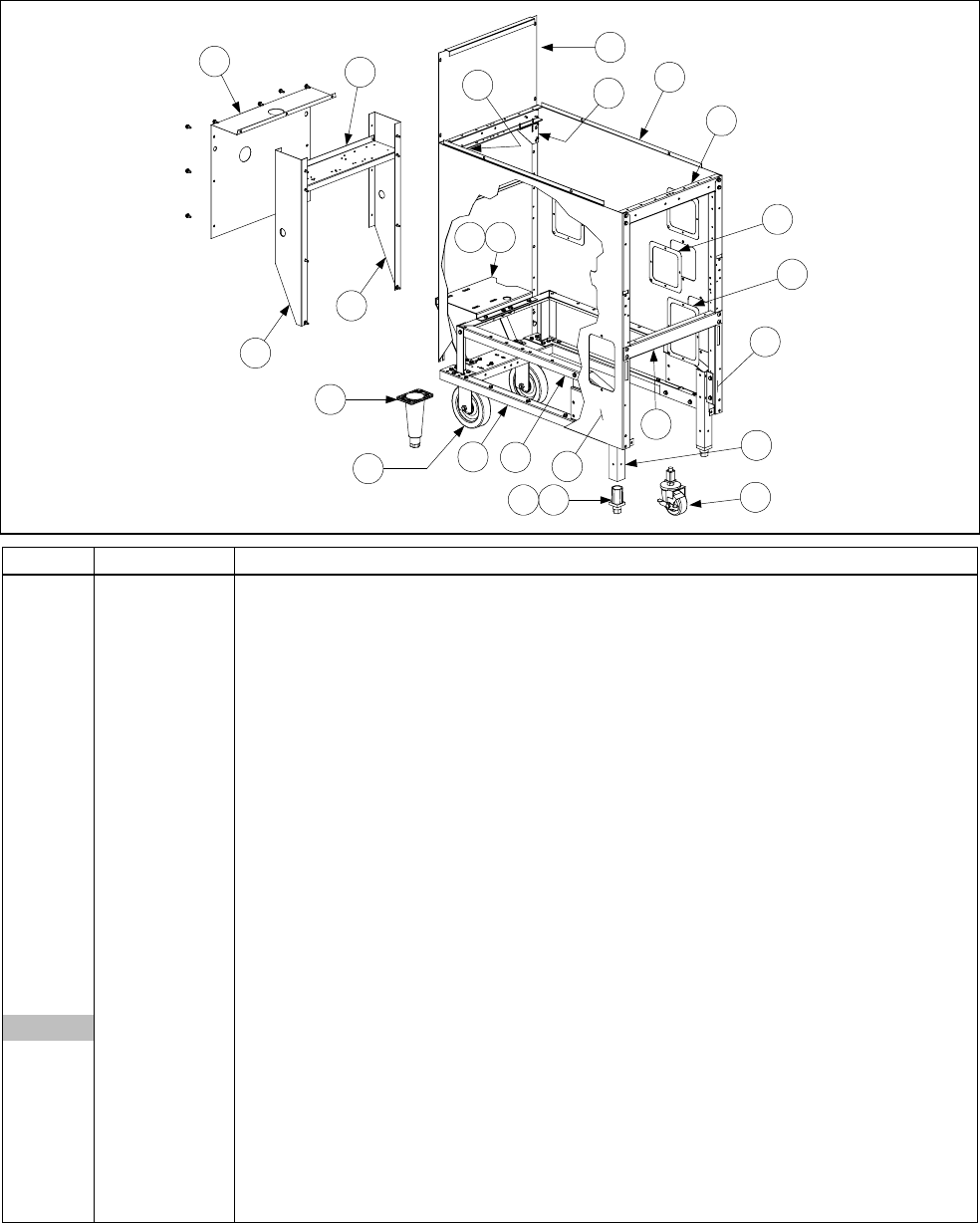
2-10
2.5 Cabinet Assemblies and Component Parts
2.5.1 FPH150 Cabinet Assembly
1
2
3
4
6
5
8
910
11
127
13
14
15
16
17
20
21
23
24
1918 22
ITEM PART # COMPONENT
1 900-7448 Back, Cabinet
2 806-4897SP Base Assembly (includes leg pad assembly 806-5209SP (see Page 2-13))
3 900-4391SP Brace, Cabinet, Front
4 900-4813SP Brace, Cabinet, Top
5 901-1405 Gusset, Left
6 902-1405 Gusset, Right
7 900-4551 Motor Mount
8 900-1621 Plate, Rail Mount (located inside lower front edge of Items 10 and 11)
9 806-5317SP Rail Assembly
10 911-9324 Side, Cabinet, Stainless Steel, Left (use 901-9324SP for enameled cabinets)
11 912-9324 Side, Cabinet, Stainless Steel, Right (use 902-9324SP for enameled cabinets)
12 900-1786 Support, Motor Mount
13 902-7447 Rear Extension, Right Side
14 901-7447 Rear Extension, Left Side
15 900-4555 Bracket, Transformer Mounting
16 900-4558 Cover, Rear Extension
17 910-1601 Leg, Filter Cabinet (use 910-8673 on units with rear casters (Item 20))
910-7925 Leg, 6” Single w/ Caster front (use w/ caster 823-2669) (White Castle)
18 810-0007 Leg, Adjustable (Inserts into Item 17)
19 910-1832 Retainer, Leg (Holds Item 18 in Item 17)
20 806-5043 Leg, 6 “ Adjustable
21 810-0750 Caster, 5” Rigid
22 823-2669 Caster, Single FootPrint front
23 910-0889 Cover, Access 5” x 5” SS for 4” x 4” Hole (use 900-0889 for enameled cabinets)
24 910-0890 Cover, Access 5” x 7” SS for 4” x 6” Hole (use 900-0890 for enameled cabinets)
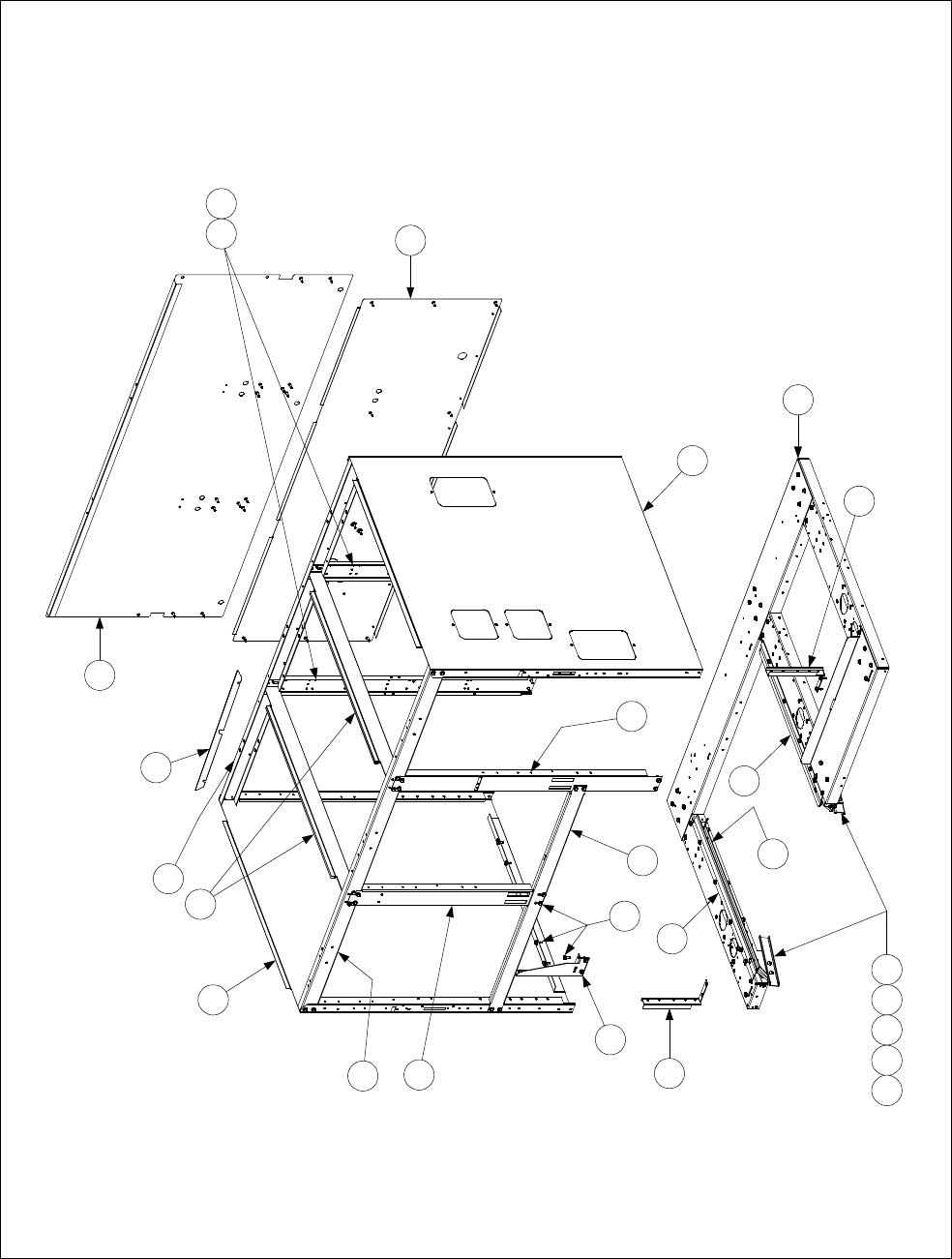
2-11
2.5.2 FPH50 Batteries
1
2
3
6
17
15
16
8
9
12
13
18 19 20
10
18
11 21
FPH50 MULTI-FRYER CABINET ASSEMBLIES
(FPH350 ILLUSTRATED IS TYPICAL OF ALL)
4
5
242322127
See Page 2-10 for access opening covers.
25

2-12
ITEM PART # COMPONENT
1Back, Lower Cabinet
910-7657 FPH250/FPH450 Stainless Steel (use 900-7657 for aluminized steel)
910-9416 FPH350 Stainless Steel (use 900-9416 for aluminized steel)
2Back, Upper Cabinet
910-7658 FPH250/FPH450 Stainless Steel (use 900-7658 for aluminized steel)
910-9415 FPH350 Stainless Steel (use 900-9415 for aluminized steel)
3Base Assembly (includes leg pad assembly 806-5209SP (see Page 2-13))
806-5861SP FPH250
806-5862SP FPH350
806-7085SP FPH450
4Brace, Cabinet Top, Rear
900-7327SP FPH250
900-9352 FPH350
900-2666SP FPH450
5Brace, Cabinet Top, Front
900-7730SP FPH250
900-9430SP FPH350
900-9318 FPH450
6 900-7729 Brace, Cross Cabinet (not used on CE units)
7 900-1959 Bracket, Mounting
8 901-1948 Channel, Side Support, Left
9 902-1948 Channel, Side Support, Right
10 900-7326 Divider, Cabinet
11 901-1810 Gusset, Cabinet, Left
* 902-1810 Gusset, Cabinet, Right (used on FPH250 only)
12 900-1957 Lock, Filter
13 900-7734 Post, Door, Long
14 900-4773SP Post, Door, Short (use 900-2567 on CE units)
15 911-4690 Rail, Filter, Top, Left
16 912-4690 Rail, Filter, Top, Right
17 910-5244 Rail, Filter, Universal
18 Side, Cabinet
910-7678SP Stainless Steel with no access openings
900-7678SP Enameled with no access openings
912-7679 Stainless Steel with access openings (used on Filter Ready units only)
902-7679SP Enameled with access openings (used on Filter Ready units only)
19 809-0413 Spacer, Nylon
20 900-4815 Support, Cabinet Rear
21 826-1374 Screw, #10 X ½-inch Hex Washer Head (Pkg. of 25)
22 809-0422 Screw, 10-32 X 7/16-inch Slotted Truss Head
23 809-0189 Washer, ¼-inch Flat
24 809-0053 Nut, 10-32 Hex
25 900-4253 Flueclip Retainer
Component Heat Shields
* 901-4314 Heat Shield Left
* 902-4315 Heat Shield Right
* 900-4833 Heat Shield Center
* Not illustrated.
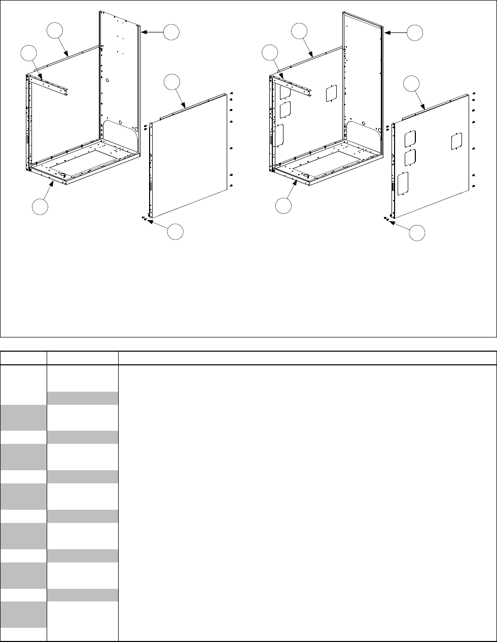
2-13
2.5.3 FH150, MJH150, and Spreader Cabinets
34
11
22
57
8
6
99
NOTES: Complete Spreader Cabinet Assemblies are : 806-6495SP (S/S) and 806-6496SP (CR).
Complete Fryer Cabinet Assemblies are: 806-46232SP (S/S) and 806-46231SP (CR).
Fryer and spreader cabinet assemblies are identical except for the backs — spreader backs do
not have a formed edge at the top. Cabinet sides with access openings are used on FH150 units
or on spreader cabinets placed in batteries of fryers equipped with built-in filtration systems.
Spreader Cabinet
(Typical) Fryer Cabinet
(Typical)
See Page 2-10 for
access opening covers.
ITEM PART # COMPONENT
1 900-2568SP Base, Cabinet, One-Piece
2 900-4813SP Brace, Cabinet Top
3Back, Spreader Cabinet
910-6983SP Stainless Steel
900-6983SP Aluminized Steel
4Back, Fryer Cabinet
910-7213SP Stainless Steel
900-7213SP Aluminized Steel
5Side, Left Cabinet w/o Access Openings
911-9323SP Stainless Steel
901-9323SP Enameled
6Side, Right Cabinet w/o Access Openings
912-9323SP Stainless Steel
902-9323SP Enameled
7Side, Left Cabinet w/Access Openings
911-9324SP Stainless Steel
901-9324SP Enameled
8Side, Right Cabinet w/Access Openings
912-9324SP Stainless Steel
902-9324SP Enameled
9 826-1374 Screw, #10 X ½-inch Hex Washer Head (Pkg. of 25)
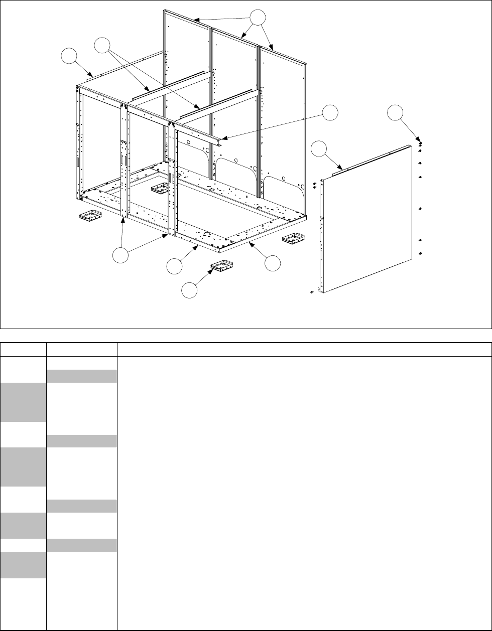
2-14
2.5.4 MJH50 Batteries
21
5
4
6
7
9
8
10
3
MJH50 MULTI-FRYER CABINET ASSEMBLIES
(MJH350 ILLUSTRATED IS TYPICAL OF ALL)
ITEM PART # COMPONENT
1 900-4426SP Channel, Left and Right Side
2Channel, Front and Rear
900-2395SP Double
900-2396SP Triple
900-9373 Quad
3 900-6979SP Post, Door
4Brace, Cabinet Top
900-7730SP Double
900-9430SP Triple
900-9318 Quad
5 806-5209SP Leg Pad Assembly
6Side, Left Cabinet
911-9323SP Stainless Steel (use 911-9324SP for side with access openings)
901-9323SP Enameled (use 901-9324SP for side with access openings)
7Side, Right Cabinet
912-9323SP Stainless Steel (use 912-9324SP for side with access openings)
902-9323SP Enameled (use 902-9324SP for side with access openings)
8 900-6983SP Back, Cabinet
9 900-7326 Divider, Cabinet
10 826-1374 Screw, #10 X ½-inch Hex Washer Head (Pkg. of 25)
* 826-1494 Kit, Jack in the Box Filter Magic Cold Air Block
* Not illustrated.
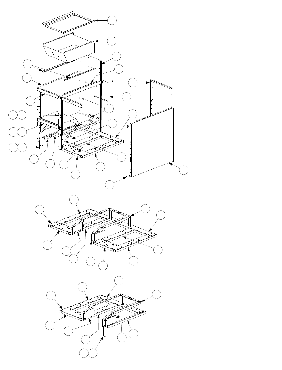
2-15
2.5.5 FMH50 Batteries with Built-In Filtration
FMH150 (FILTER ON RIGHT)
(All components except Items 27 and 28
are the same for FMH250 and FMH350
units with the filter on the right.)
1716
24
27
23
25
19
21
29
26
28
FMH250 (FILTER BETWEEN FRYERS)
(All components except Items 27 and 28
are the same for FMH350 cabinets with
the filter between fryers.)
25
24
28
26
27
27
25
20
26
29
19
FMH150 (FILTER ON LEFT)
(All components except Items 27 and
28 are the same for FMH250 and
FMH350 units with the filter on the
left.)
1
2
3
4
6
5
7
8
9
1716
18
22
20
14
27
25
26
28
1312
NOTE: Items 1-15 are used in
all FMH50 Builit-In Filter
configurations and therefore are
not repeated for the FMH250
and FMH150 (Filter on Right)
illustrations.
22
1110
29
15
(See Page 2-14 for Leg Pad Assembly)

2-16
ITEM PART # COMPONENT
1 910-7480 Trim, Filter Cabinet Top
2 806-8274SP Pan Assembly, Filter/Spreader Cabinet
3 900-7277 Support, Drain Pan
4Back w/Access Opening, Filter Cabinet
910-7274SP Stainless Steel
900-7274SP Aluminized Steel
5 900-4089 Cover, Cabinet Back Access
6Back, Cabinet
910-6983SP Stainless Steel
900-6983SP Aluminized Steel
7Side, Left Cabinet
911-9323SP Stainless Steel
901-9323SP Enameled
8Side, Right Cabinet
912-9323SP Stainless Steel
902-9323SP Enameled
9 900-7414 Shield, Filter Magic Pan
10 900-6979SP Post, Door
11 809-0413 Spacer, .25 x .160 8 Gauge Nylon (located behind Item 10 at bottom)
12 900-4391SP Brace, Front Cabinet
13 826-1379 Screw, #10 x ½-inch Philips Truss Head (package of 10)
14 900-1700 Bracket, Drain Support
15 900-7314SP Divider, Cabinet
16 910-1601 Leg, Filter
17 900-1621 Plate, Rail Mount (located inside front edge of Item 7)
18 901-1599 Bracket, Left Pan Rail (used on cabinets with filter on left)
19 901-1595 Bracket, Left Pan Rail (used on cabinets with filter on right or in middle)
20 902-1599 Bracket, Right Pan Rail (used on cabinets with filter on right or in middle)
21 902-1595 Bracket, Right Pan Rail (used on cabinets with filter on right)
22 901-4390 Channel, Left Filter Side
23 902-4390 Channel, Right Filter Side
24 806-4917 Rail Assembly, Filter Magic
25 900-4426 Channel, Fryer Outside
26 900-4383 Channel, Fryer Inside
27 Channel, Fryer Front
900-2394 Single Fryer
900-2395 Double Fryer
900-2396 Triple Fryer
28 Channel, Filter Magic Cabinet Rear
900-1631 FMH150 Filter Left
900-7243 FMH250 Filter Left
900-9319 FMH350 Filter Left
900-1630 FMH150 Filter Right
900-7244 FMH250 Filter Right
900-9322 FMH350 Filter Right
900-7242 FMH250 Filter Middle
900-9321 FMH350 (Fryer, Fryer, Filter, Fryer)
900-9320 FMH350 (Fryer, Filter, Fryer, Fryer)
29 826-1374 Screw, #10 X ½-inch Hex Washer Head (Pkg. of 25)
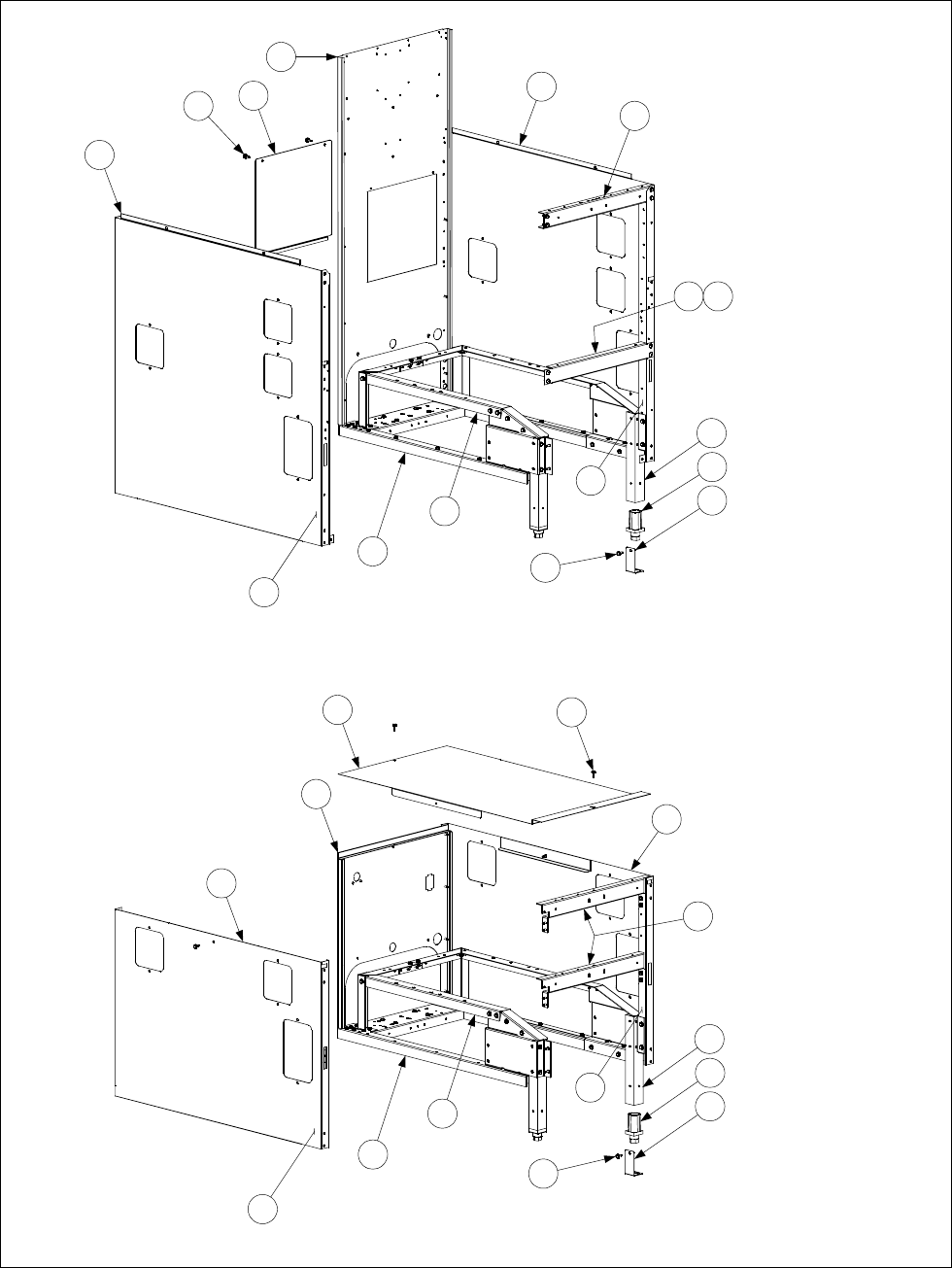
2-17
2.5.6 Filter Magic Add-On Cabinetry
NOTE: Items 1-3 and 9
from Page 2-16, and Item
20 or 21 from Page 2-10
are also used in this
cabinet.
NOTE: Item 9 from Page
2-16, and Item 20 or 21
from Page 2-10 are also
used in this cabinet.
UNDERCOUNTER ADD-ON
FILTER MAGIC CABINET
ADD-ON
FILTER MAGIC CABINET
1
2
3
18 4
5
6
7
818
9
11
12
12
13
13
14
14
14
14
15
16
17
18
15
16
17
18
10 19
See Page 2-10 for access opening covers.

2-18
ITEM PART # COMPONENT
1Side, Left Cabinet, w/Access Openings
911-9324SP Stainless Steel
901-9324SP Enameled
2Side, Right Cabinet, w/Access Openings
912-9324SP Stainless Steel
902-9324SP Enameled
3Back w/Access Opening, Filter Cabinet
910-7274SP Stainless Steel
900-7274SP Aluminized Steel
4 900-4089 Cover, Cabinet Back Access
5Side, Left Undercounter Cabinet
911-7677SP Stainless Steel
901-7677SP Enameled
6Side, Right Undercounter Cabinet
912-7677SP Stainless Steel
902-7677SP Enameled
7Back, Undercounter Cabinet
910-4786 Stainless Steel
900-4786 Aluminized Steel
8 910-7680 Cover, Undercounter Cabinet
9 900-4813SP Brace, Cabinet Top
10 900-4391SP Brace, Cabinet Front
11 900-4785 Brace, Undercounter Cabinet Top and Center
12 806-5317SP Rail Assembly
13 806-4897SP Base Assembly (includes leg pad assembly 806-5209 (see Page 2-13))
14 900-1621 Plate, Rail Mount (located inside lower front edge of Items 1, 2, 5, and 6)
15 910-1601 Leg, Filter Cabinet (use 910-8673 on units with rear casters)
16 810-0007 Leg, Adjustable
17 910-1832 Retainer, Leg Insert, Full Height
18 826-1374 Screw, #10 X ½-inch Hex Washer Head (Pkg. of 25)
19 826-1379 Screw, #10 X ½-inch Philips Truss Head (Pkg. of 10)
* 910-8503 Front Panel HE Filter Magic
* 802-0391 Label, FMII Control Panel
* 900-8906 Liner, Floor One Piece Base
* 901-1599 Bracket, Left Pan Rail Leg
* 902-1599 Bracket, Right Pan Rail Leg
* 910-0889 Cover, 4” Cabinet Side Hole S/S
* 910-0890 Cover, 7” Cabinet Side Hole S/S
* Not illustrated
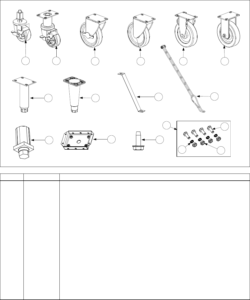
2-19
2.6 Casters, Legs, and Restraints
1 2 3 5 6
7 8 910
4
11 12 13
14 15
16 17
ITEM PART # COMPONENT
1 823-2669 Caster, Single FootPrint Front
* 910-7925 Mounting Leg for Caster 823-2669
2 826-1130 Caster, 3” Swivel w/Brake (810-0651)
3 826-1118 Caster, 5” Swivel w/Brake (810-0357)
4 826-1117 Caster, 5” Swivel w/o Brake (810-0356)
5 826-1138 Caster, 5” Rigid w/o Brake (810-0378)
6 826-1114 Caster, 5” Rigid w/o Brake (810-0750)
7 826-1237 Leg Assembly, Stainless Steel (810-1205)
8 826-1115 Leg Assembly, Nickel Plated (806-5043)
9 826-1095 Anchor Strap Kit (for use on single fryers w/legs)
10 826-0900 Chain Restraint Kit (for use on fryers w/casters)
11 810-0007 Leg, Square Tube
12 806-5209SP Leg Pad (mounts with 826-1374)
13 826-1374 Screw, #10-1/2 HX Washer HD NP
14 826-1113 Caster Fastener Kit (One Caster)
15 826-1389 Screw, Hex Head ¼-20 x ¾
16 809-0191 Washer, ¼ Lock Spring ZP
17 826-1362 Nut, ¼-20 Hex
NOTE: Items 2 through 8 include 1 caster or leg, 4 mounting bolts, and 4 lock washers.

2-20
2.7 Component Box Assemblies and Associated Component Parts
IFB 806-3398 (Discontinued) has only one
fuse. If used with 807-3365 or 807-3366
modules, an in-line fuse should be added
between the module and the board.
Replaced by 106-0386
Full vat units using one 807-3366 module
(Item 3) require only one latch relay (Item 5).
Full or dual vat units using two 807-1006,
807-2971, or 807-3365 modules require a
latch relay (Item 5) for each module.
IFB 106-0386 (Item 7) has two
fuses and may be used with any
of the ignition modules.
1
2
8
9
10 12
11 13
14
6
515
16
17
2
3
4
4
7
7
5
5
6
ITEM PART # COMPONENT
1 200-5996 Box Assembl
y,
One-Piece Com
p
onent
2 807-1006 I
g
nition Module, Full or Dual Vat
(
fuse-
p
rotected
)
* 807-2971 I
g
nition Module, Full or Dual Vat
(
fuse-
p
rotected
)
(
Australian units onl
y)
3 807-3366 I
g
nition Module, Full Vat
(
unfused
)
4 807-3365 I
g
nition Module, Dual Vat
(
unfused
)
use 1 wire 1 connector ign. cable 826-2024
5 807-0833 Rela
y
, 12V 5Am
p
Latch (use Relay Clip 810-2243 to secure relay in place)
* 807-0834 Rela
y
, 12V 5Am
p
Basket Lift (use Relay Clip 810-2243 to secure relay in place)
6 807-3843 Fuse, 3A 250V Subminature
7 106-0386 Interface Board
(
double fuse-
p
rotected
)(
use w/ 807-3365, 807-1006 or 807-3366
)
* 806-4973 Interface Board
(
used with 240V manufactured
g
as units onl
y)
* 806-3683 Interface Board
(
used with Ger. fr
y
ers with 24V blowers onl
y)
use 5A fuse 807-3293
* 106-3044 Interface Board, FAST Com
p
uter (uses 807-3969 latch relay in place of Item 5)
* 806-3641 Interface Board,
(
used in Holland
)
* 806-4195SP Interface Board,
(
used with manufactured
g
as Hon
g
Kon
g)
* 806-3535 Interface Board,
(
used in Churches w/ Far West Com
p
uters
)
8 807-1926 Bushin
g
, .875 Diameter S
p
lit
9 816-0217 Pa
p
er, Insulatin
g
(
Items 9, 10, 11, 12 not used on Hon
g
Kon
g
units
)
10 810-1164 Block, Terminal
(
See Item 9
)
11 826-1359 Screw, 4-40 x ¾-inch Slotted Round Head
(
See Item 9
)
(
Pk
g
. of 25
)
12 826-1366 Nut, 4-40 Ke
p
s Hex
(
See Item 9
)
(
Pk
g
. of 25
)
13 807-1241 S
p
acer, Interface Board
(
.151-inch ID x ⅝-inch
)
14 809-0250 Nut, 6-32 Ke
p
s Hex
15 826-1337 Tab, Push-On Terminal
(
Pk
g
. of 5
)
16 826-1346 S
p
acer, I
g
nition Module
(
.260-inch ID x ½-inch
)
(
Pk
g
. of 10
)
17 809-0441 Screw, #7 x 1½-inch Slotted Washer Hex Hea
d
* 826-1157 Fuse Kit, I
g
nition Module 3 Am
p
(
fuse and fuse
p
uller
)
* 806-2071 Com
p
uter Cable 15-
p
in
* 806-3660 Sound Device (For units with KFC1 Computers, use Speaker 807-1617)
* 807-1359 Mount, Tie-Wra
p
(
used on CE units onl
y)
* Not illustrated.

2-21
2.8 Control Panel Assemblies, Flue Caps, Top Caps, and Related Components
657
651
652
653
8
9
10
11 12 13
14
15
16
17
18
19
20
21
22
23
24
25
26
27
4

2-22
ITEM PART # COMPONENT
1 810-2793 Basket Hanger, Wire Form
2 803-0028 Basket Hanger, Extruded Aluminum (replaced by 810-2793)
3 823-1462 Basket Hanger, Burger King
* 106-2186 Basket Hanger Assembly, Burger King (includes Items 1, 4 and 13)
4 106-2185 Bracket, Burger King Easy-Off Basket Hanger (used w/Item 1)
5 809-0171 Thumbscrew, ¼-20 X 1⅜-inch Basket Hanger
* 809-0921 Spacer, Basket Hanger
6 826-1351 Nut, Cage (receives Basket Hanger Thumbscrew) (Pkg. of 10)
7 806-9257SP Roller Assembly, Basket Lift (Complete)
8 910-8284 Bracket, One-Piece Roller Guide
9 826-1334 Capscrew, ¼ – 20 x 1¼” Stainless Steel Hex Head (Pkg. of 5)
10 809-0190 Washer, ¼” Stainless Steel Flat
11 810-0374 Spacer, Tubular
12 810-0194 Roller, Basket Lift Guide
13 809-0047 Nut, ¼ – 20 Cap (also used w/Item 4)
14 Flue Cap, Single Fryer, w/lip
910-5018 Standard (use 910-5019 on Burger King fryers)
910-6545 Optional (without lip along flue opening)
823-3749 Burger King with Button Studs (used w/Item 4)
15 Flue Cap, 2-Fryer Battery
823-2540 Standard (use 823-2542 on Burger King fryers)
823-3536 Burger King with Button Studs (used w/Item 4)
16 Flue Cap, 3-Fryer Battery (use 823-2543 on Burger King fryers)
823-2541 Standard (use 823-2543 on Burger King fryers)
823-3537 Burger King with Button Studs (used w/Item 4)
17 823-2569 Flue Cap, 4-Fryer Battery
823-3538 Burger King with Button Studs (used w/Item 4)
18 900-5486 Support, Flue Cap
19 900-4253 Flue Cap Retaining Strip, Burger King
* 910-3557 Flue Deflector
20 Top Cap, Single Fryer
824-0404 Standard
824-0408 H50 side of H50/FB18 Battery
21 824-0405 Top Cap, Two-Fryer Battery
22 824-0406 Top Cap, Three-Fryer Battery
23 824-0407 Top Cap, Four-Fryer Battery
24 Control Panel Assembly, Single Fryer
806-4732SP Standard (see Note 1)
806-5363SP H50 side of H50/FB18 Battery
25 806-4733SP Control Panel Assembly, 2-Fryer Battery (see Note 2)
26 806-4734SP Control Panel Assembly, 3-Fryer Battery (see Note 3)
27 806-5018SP Control Panel Assembly, 4-Fryer Battery (see Note 4)
* 826-1379 Screw, #10 X ½-inch Philips Head (Pkg. of 10) (attaches top cap)
* 826-1371 Screw, #8 X ½-inch Hex Washer Head (Pkg. of 25) (attaches flue cap)
* Not illustrated.
NOTES:
1. Use 806-9712SP on KFC fryers; use 106-2927SP for units with fallback controllers.
2. Use 806-9713SP on KFC fryers; use 106-2928SP for units with fallback controllers.
3. Use 806-9714SP on KFC fryers; use 106-2929SP for units with fallback controllers.
4. Use 806-9715SP on KFC fryers.

2-23
2.9 Controller Assemblies
SOLID STATE
1 2 3 4
ITEM PART # COMPONENT
1Computer Magic III
106-1187SP Dual Vat (CE)
106-1151SP Dual Vat (Non-CE)
106-1155SP Dual Vat w/ 8 sec. Melt Cycle
106-1188SP Full Vat (CE)
106-1150SP Full Vat (Non-CE)
106-1216 Full Vat, Remote BK on the Hood
106-1226 Full Vat, Remote BK in the Hood
2Basket Lift Timer
106-2081SP Dual Vat (CE)
106-2074SP Dual Vat (Non-CE)
106-2077SP Full Vat (CE)
106-2073SP Full Vat (Non-CE)
826-1552 Kit, 120v Push Button 15 min timer retrofit
826-1667 Kit, 240v Push Button
3Digital Controller
106-1506SP Dual Vat (CE)
106-1510 Dual Vat (Non-CE)
106-1505SP Full Vat (CE)
106-1509SP Full Vat (Non-CE)
4Solid State (Analog) Controller (Controller Knob is 810-0387)
806-3564E Dual Vat (CE) w/ 8 sec. Melt Cycle
806-3008E Dual Vat (Non-CE)
806-3563E Full Vat (CE) w/ 8 sec. Melt Cycle
806-3006E Full Vat (Non-CE) (for Foodmaker units, use 806-7385)807-2236 Overlay
* 106-0613 CM4-S Computer (CE)
* 806-4323 Fallback Controller Assembly
Continued on the following page
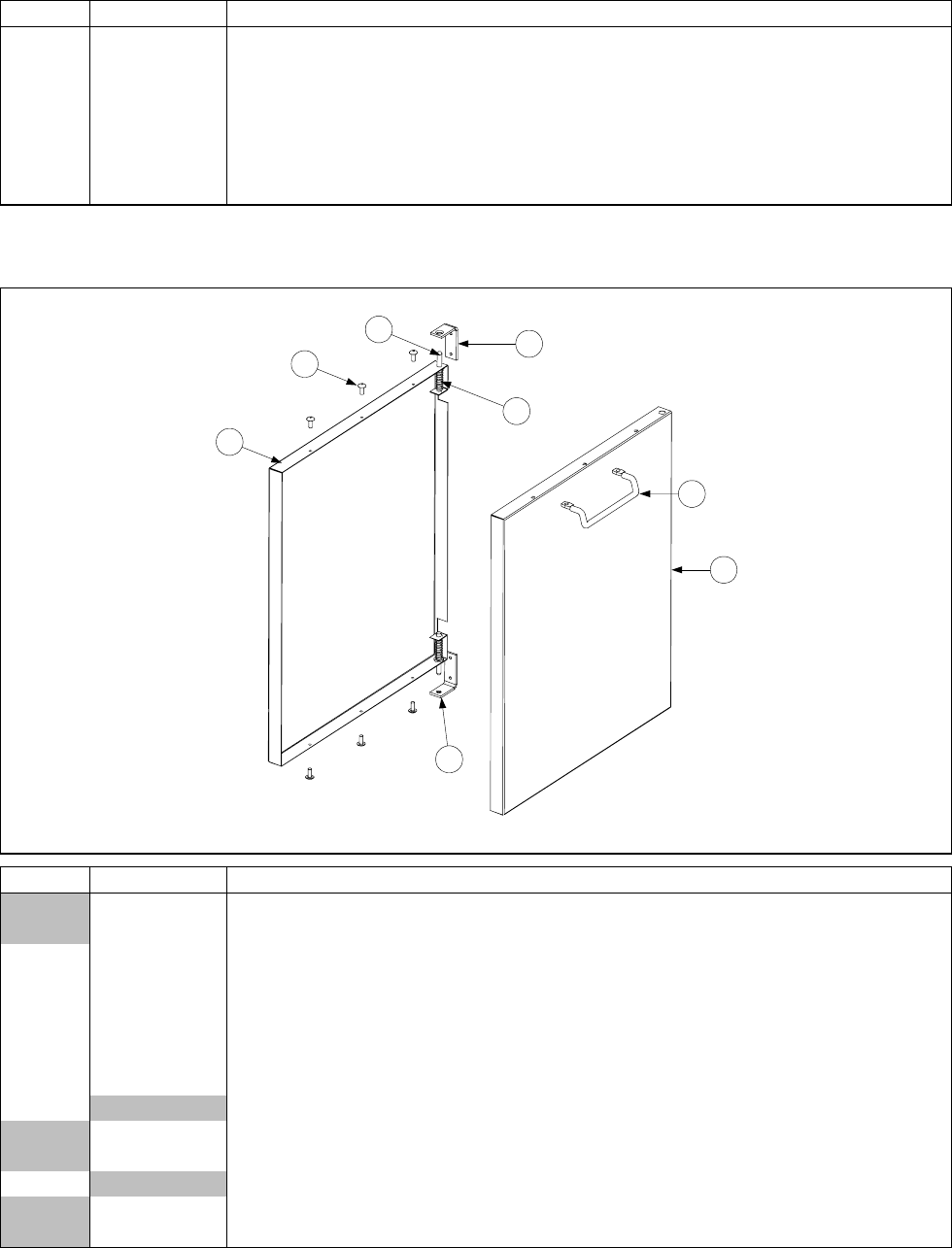
2-24
2.9 Controller Assemblies cont.
ITEM PART# COMPONENT
* 806-5300 KFC1 Computer (requires special control panel assembly – see Page 2-22)
* 826-1032SP Kit, Bezel Screw and Tinnerman Clip (contains two screws and two clips)
* 826-1379 Screw, #10 X ½-inch Philips Truss Head (computer screws) (Pkg. of 10)
* 910-3690 Blank Panel (for fryers with remote mounted computers)
* 806-2071 Harness, Main Short Wire 14 ½” 15-pin Computer to Interface Board
* 806-3528 Harness, Main 7 ½’ BK 15-pin Computer to Interface Board
* 806-3388 Harness, Main 20’ Remote N Pot 15-pin Computer to Interface Board
* Not illustrated.
2.10 Door Assemblies
3
1
4
7
6
2
5
5
ITEM PART # COMPONENT
806-1962SP Door Assembly, Complete (for use on MJH50 and FMH50 units)
806-6405SP Door Assembly, Complete (for use on FPH50 units)
1 806-4487SP Door Pin Assembly
2 826-1343 Spring, Door Pin (Pkg. of 10)
3 810-1422 Handle, Door, Wireform, Stainless Steel (must be ordered separately)
4 826-1379 Screw, #10 x ½” Phillips Head, Zinc Plated (Pkg. of 10)
5 810-1508 Hinge, Door, Universal (must be ordered separately)
6 824-0616 Panel, Door, Outer
7Liner, Door
900-6595 Used with 806-1962SP
900-4807 Used with 806-6405SP
*Magnet, Door
810-0066 Used with 806-1962SP on Door
810-1105 Used with 806-6405SP on Frame
* Not illustrated.
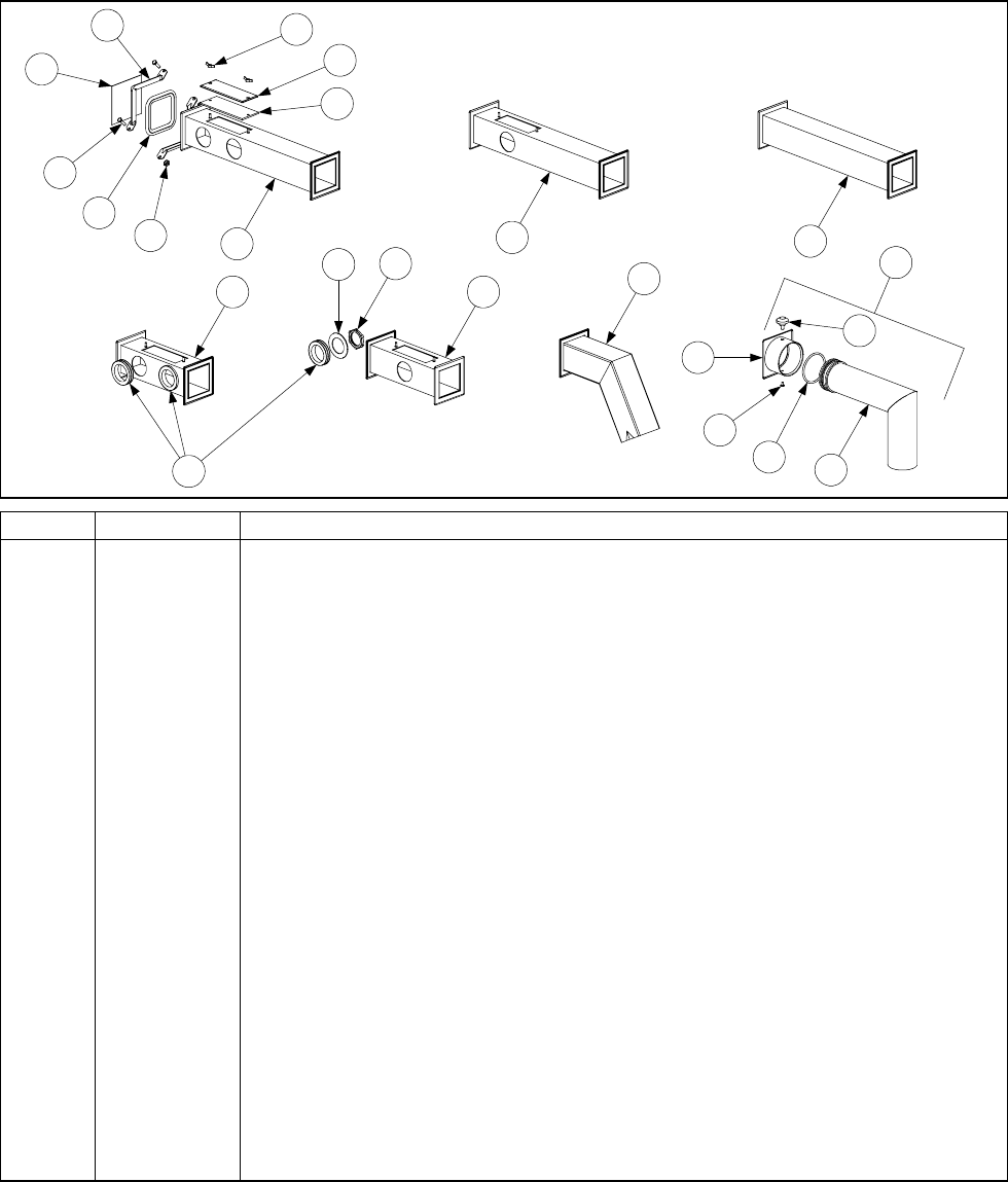
2-25
2.11 Drain System Components
2.11.1 Filter Magic II Square Drain Components, Standard Configuration (Units Built Before
03/01/01)
1
2
3
4
6
5
9
8
10
11 12
13
14
15
7
17
18
20
21
22 23
16
19
ITEM PART # COMPONENT
1 810-0396 Clamp Section (requires 2 per connection)
2 826-1362 Nut, ¼–20 (Pkg. of 10)
3 826-1375 Screw, 10–32 x ¾ (Pkg. of 5)
4 816-0032 Seal (Connection Gasket)
* 826-0877 Kit, Clamp Assembly (2 each of Items 1, 2, and 3, and 1 of Item 4)
5 826-1348 Cover, Cleanout (Pkg. of 5)
6 816-0021 Gasket, Cleanout
7 826-1382 Wing Nut, Cleanout Cover Retaining (Pkg. of 10)
8 900-0757 Cover, Drain End
9 823-0724 Drain Tube, Dual Vat, 15.5” Long
10 823-0717 Drain Tube, Full Vat, 15.5” Long
11 823-0725 Drain Tube, Closed End, Dual Vat, 8.12” Long
12 823-0718 Drain Tube, Closed End, Full Vat, 8.12” Long
13 823-0731 Drain Tube Extension, Spreader Cabinet, 15.5” Long
14 823-0719 Drain Outlet, Fixed
15 806-4068SP Drain Outlet Assembly, Swivel (contains 1 each of Items 16-20)
16 823-1091 Drain Tube, Swivel
17 823-1092 Collar, Drain
18 809-0115 Screw, 10–32
19 810-0388 Knob, Clamping
20 816-0083 O-Ring, 2.5” ID
21 816-0092 Grommet, 1-inch Drain Tube
22 826-1345 Washer, Drain Tube Retaining (Pkg. of 25)
23 809-0347 Nut, Drain Tube Retaining
* Not illustrated.

2-26
2.11.2 Filter Magic II Square Drain Components, Non-Standard Configurations (Units Built
after 03/01/01)
1
2
3
5
4
6
7
8
9
11
14
15
16
17
12
13
18
19
20
10
21
22
23
24
25
ITEM PART # COMPONENT
1 806-6374 Clamp Assembly
2 816-0420 Boot (Connection Seal)
3 KIT-0257SP Clamp Assembly and Boot Kit (contains 2 of Item 1 and 1 of Item 2)
4 816-0123 Cap, Square Drain End
5 KIT-0256SP Kit, Square Drain End Cap (contains 1 each of Items 1 and 4)
6 816-0021 Gasket, Cleanout
7 826-1348 Cover, Cleanout (Pkg. of 5)
8 826-1382 Wing Nut, Cleanout Cover Retaining (Pkg. of 10)
9 823-1701 Drain Tube, 15” Long, Open Both Ends
10 823-2128 Drain Tube, 8.3” Long, Open at Both Ends
11 823-1697 Swivel Drain Receiver, Filter Left of Fryer
12 823-1698 Swivel Drain Receiver, Filter Right of Fryer
13 823-1702 Drain Tube, 8.3” Long, Left End Closed
14 823-1091 Drain Outlet, Swivel
15 810-0388 Knob, Clamping
16 809-0115 Screw, 10–32
17 816-0083 O-Ring, 2.5” ID
18 816-0124 Washer, Fiber
19 826-1345 Washer, Drain Tube Retaining (Pkg. of 25)
20 809-0347 Nut, Drain Tube Retaining
21 823-2225 Drain Section, Dual Vat, 11.55” Long
22 823-3755 Drain Elbow, Full Vat Left or Right, 13.8” Long
23 823-3052 Drain Elbow, Dual Vat Left or Right, 9.7” Long
24 823-2221 Drain End, Dual Vat Left or Right
25 823-2212 Drain Section, Dual Vat Left or Right
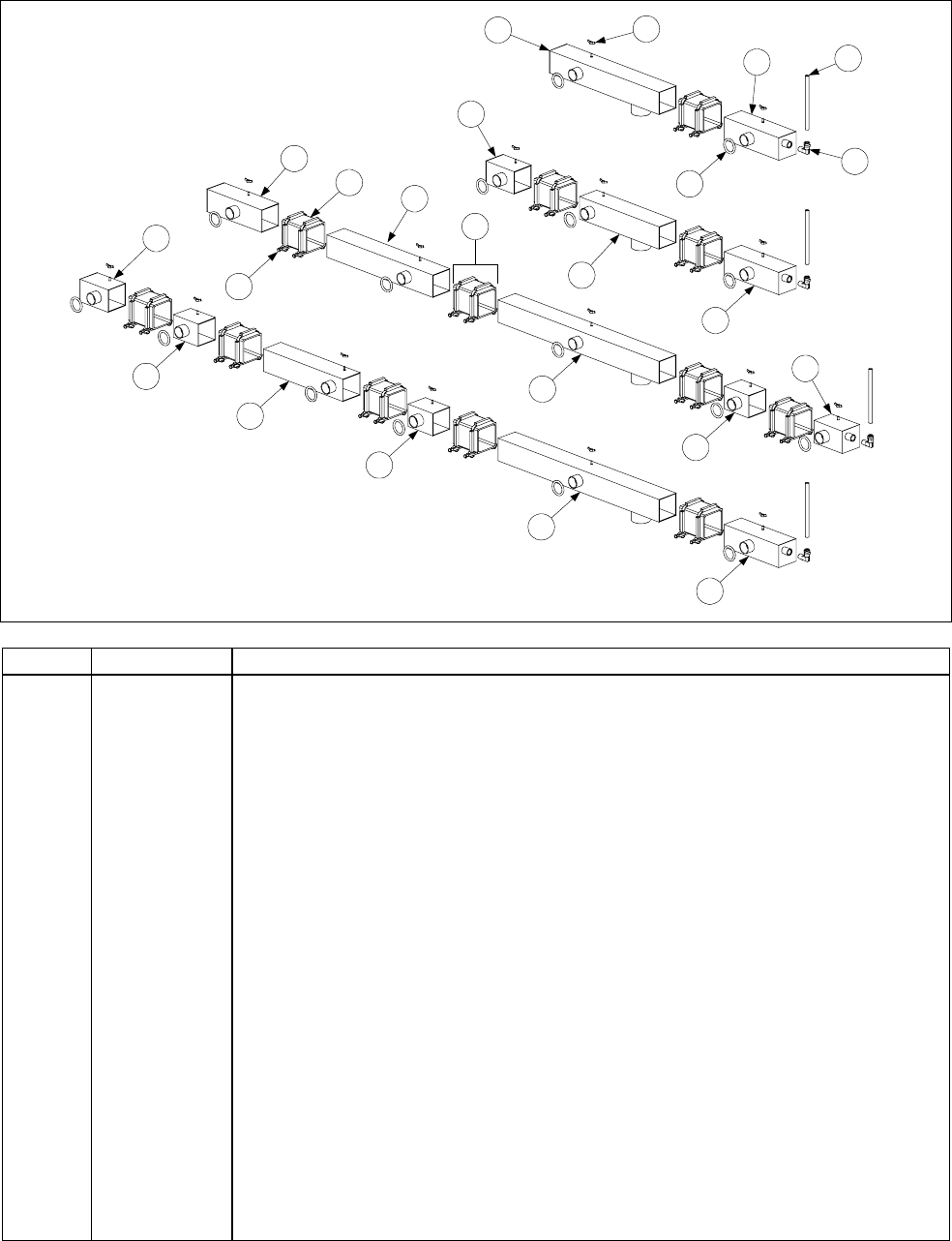
2-27
2.11.3 FootPrint III Square Drain Components, Standard Configuration
NOTE: The assemblies shown represent typical FP III standard
drain configurations. All components are illustrated, but there are
many other possible combinations of these components.
5
6
15
12
14
18
17
16
13
16
12
9
9
9
7
10
2
1
3
8
11
17
4
FPH250
FPH250-2R
FPH450-2L
FPH450-4R
ITEM PART # COMPONENT
1 806-6374 Clamp Assembly
2 816-0420 Boot (Connection Seal) 3 ½”
3 KIT-0257SP Clamp Assembly and Boot Kit (contains 2 of Item 1 and 1 of Item 2)
4 826-1382 Wing Nut (Pkg. of 10)
5 811-0932 Vent Tube, Teflon, ⅜” OD (FP III units manufactured after Sep 97) per foot
6 810-1372 Fitting, 90°, Vent Tube (for use with Item 5)
7 816-0135 O-Ring
8 823-2444 Left End Section, Dual Vat, 4.06” Long
9 823-2445 Left End Section, Full Vat, 7.95” Long
10 823-2231 Drain Outlet Section, Closed, 15.86” Long
11 823-2294 Drain Outlet Section, Open, Dual Vat, 11.55” Long
12 823-2223 Drain Outlet Section, Open, Full Vat, 23.38” Long
13 823-2225 Drain Section, Dual Vat, 11.55” Long
14 823-2301 Drain Section, Full Vat, 15.39” Long (Hole on Rt. 823-2316)
15 823-2193 Drain Section, Left End, Dual Vat, 3.57” Long (stud left of center)
16 823-2212 Drain Section, Right End, Dual Vat, 3.57” Long (stud right of center)
17 823-2221 Right End Section, Dual Vat, 4.06” Long
18 823-2198 Right End Section, Full Vat, 7.89” Long
* 806-8408SP Drain Assembly FPH350 w/out Rear Flush
* 806-8414SP Drain Assembly FPH 450 w/out Rear Flush

2-28
2.11.4 FootPrint III Square Drain Components, Rear Flush Configuration
NOTE: The assemblies shown represent typical FP III rear flush
drain configurations. All components are illustrated, but there are
many other possible combinations of these components.
3
1
2
10
10a
9
4
5
6
7
13
15
19 11
11a
18
17
14
17
12
9
3
16
FPH250
FPH250-2R
FPH450-2L
FPH450-4R
ITEM PART # COMPONENT
1 806-6374SP Clamp Assembly
2 816-0420 Boot (Connection Seal)
3 KIT-0257SP Clamp Assembly and Seal Kit
4 826-1382 Wing Nut (Pkg. of 10)
5 811-0932 Vent Tube, Teflon, ⅜” OD (FP III units manufactured after Sep 97) per foot
6 810-1372 Fitting, 90°, Vent Tube (for use with Item 5)
7 816-0135 O-Ring (Valve)
8 823-2199 Left End Section, Dual Vat, 4.06” Long
9 823-2197 Left End Section, Full Vat, 7.95” Long
10 823-2211 Drain Outlet Section, Closed, Full Vat, 18.60” Long (one bracket)
10a 823-2210 Drain Outlet Section, Closed, Dual Vat, 15.86” Long (two brackets)
11 823-2204 Drain Outlet Section, Open, Dual Vat, 11.55” Long (one bracket
11a 823-2192 Drain Outlet Section, Open, Dual Vat, 11.55” Long (two brackets)
12 823-2200 Drain Outlet Section, Open, Full Vat, 23.38” Long (two brackets)
13 823-2207 Drain Outlet Section, Open, Full Vat, 23.38” Long (three brackets)
14 823-2202 Drain Section, Dual Vat, 11.55” Long (two brackets)
15 823-2233 Drain Section, Full Vat, 15.39” Long (one bracket)
16 823-2193 Drain Section, Left End, Dual Vat, 3.57” Long (stud left of center)
17 823-2212 Drain Section, Right End, Dual Vat, 3.57” Long (stud right of center)
18 823-2194 Right End Section, Dual Vat, 4.06” Long
19 823-2198 Right End Section, Full Vat, 7.89” Long
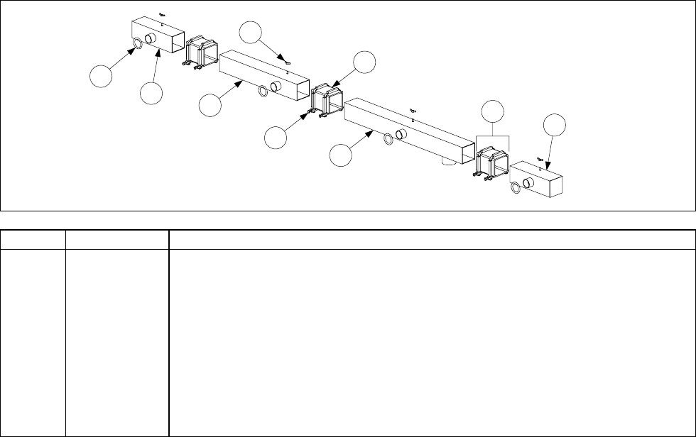
2-29
2.11.5 FootPrint III Square Drain Components, Foodmaker Configuration
1
2
4
5
3
9
8
7
6
ITEM PART # COMPONENT
1 806-6374 Clamp Assembly
2 816-0420 Boot (Connection Seal)
3 KIT-0257SP Clamp Assembly and Seal Kit
4 826-1382 Wing Nut (Pkg. of 10)
5 816-0135 O-Ring
6 823-2223 Drain Outlet Section, Open 23.38” Long
7 823-2301 Drain Section, 15.39” Long
8 823-2198 Right End Section, 7.95” Long
9 823-2222 Left End Section, 7.95” Long
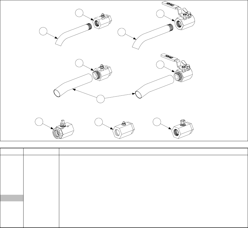
2-30
2.12 Drain Valves, Drain Valve Assemblies and Associated Parts
2.12.1 Drain Valves and Drain Extensions
3
5
6
7
8910
2
4
1
ITEM PART # COMPONENT
1 812-1227 Drain Valve Extension, Screw-In DV (1-inch NPT)
2 812-1226SP Drain Valve Extension, Screw-In FV (1¼-inch NPT)
3 210-4175 Drain Valve Extension, Bayonet Connection (used only with Items 5 and 7)
4 810-1338 Drain Valve, 1-inch NPT Inlet and Outlet, Dual Vat
5 810-2536 Drain Valve, 1-inch NPT Inlet, Bayonet Outlet, Non-Filter Dual Vat
6 810-1569 Drain Valve w/Handle, 1¼-inch NPT Inlet and Outlet, Full Vat
806-4145 Drain Valve, 1¼-inch- CF or High Sediment (Large Bore)
7 810-2535 Drain Valve w/Handle, 1¼-inch NPT Inlet, Bayonet Outlet Non-Filter FV*
8 810-1018 Drain Valve, 1¼-inch NPT Inlet, 1-inch O-Ring Outlet, ½-inch Stem, FV*
9 810-1114 Drain Valve, 1¼-inch NPT Inlet, 1-inch O-Ring Outlet, ⅜-inch Stem, DV*
10 810-1020 Drain Valve, 1¼-inch NPT Inlet, 1-inch NPT Outlet, Full Vat (Filter Magic Unit)
* Full Vat and Dual Vat
Application Notes: Item 4 is used on non-filter, Filter Magic, and FootPrint III units. Items 5, 6, and 7
are used only on non-filter units. Items 8 and 9 are used only on FootPrint III units. Item 10 is used on
Filter Magic units.

2-31
2.12.2 MJH50 Drain Valve Assemblies
3
4
1
1
2
2
806-7915SP
806-7916SP
Dual-Vat (1-inch) Assemblies
ITEM PART # COMPONENT
806-7915SP Complete Assembly, Left
806-7916SP Complete Assembly, Right
Components
1 810-1338 Drain Valve, 1-inch NPT Inlet and Outlet (See NOTE)
2 809-0539 Nut, 2-way Lock, ⅜–16
3 810-1568 Handle, Drain Valve, w/Lock Pin, Left
4 810-1567 Handle, Drain Valve, w/Lock Pin, Right
NOTE: For a short period in early 2003, some versions of these assemblies were manufactured with
valves having a snap-on connection at the outlet end (see Item 5 on Page 2-30). If replacing the valve in
this type assembly, use 810-2536 instead of 810-1338.
1
2
806-6993SP
806-4145SP
53
4 5
Full-Vat (1.25-inch) Assemblies
ITEM PART # COMPONENT
806-6993SP Complete Assembly, Domestic Units
806-4145 Complete Assembly, Export Units (Including CE)
Components
1 810-1017 Drain Valve, 1¼-inch Gemini – non-filter
2 809-0589 Nut, ½-inch Lock
3 810-0820 Handle, Drain Valve w/o Lock Pin (used on domestic units)
4 810-1427 Handle, Drain Valve w/Lock Pin (used on export units)
5 816-0211 Sleeve, Valve Handle
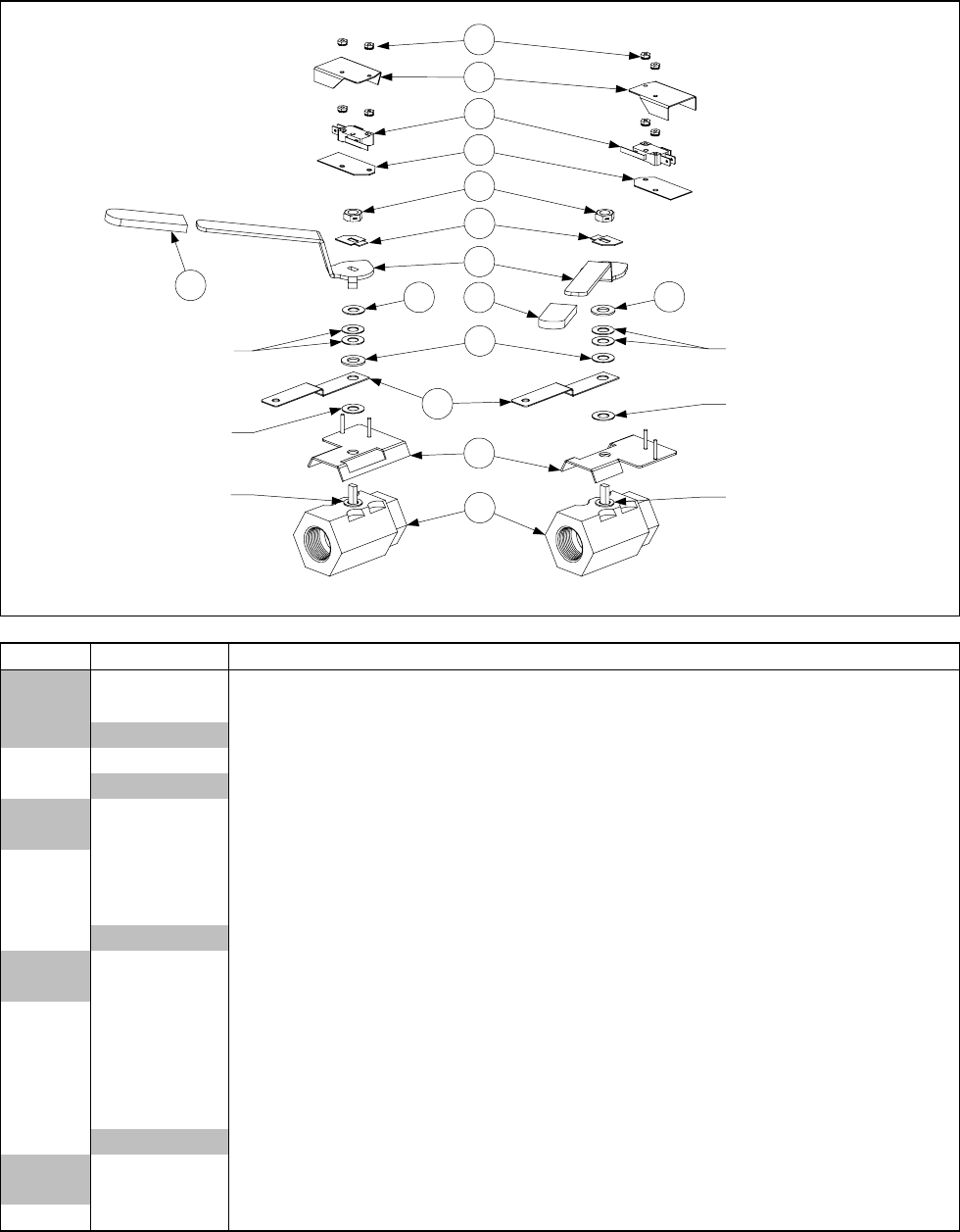
2-32
2.12.3 FMH50 Dual Vat (1-Inch) Valve Assemblies
806-7432SP806-7433SP
2
13
3
Plastic Washer
(part of Item 1) Plastic Washer
(part of Item 1)
1
4
5
6
8
77
9
10
11
12
NOTES: Compression washers must
be turned face to face and lock nut
(Item 9) must be torqued to 60 ± 10
inch-pounds.
Item 3 does not come with 806-7432SP
or 806-7433SP.
Steel Flat Washer
(part of Item 1)
Compression Washers
(part of Item 1)
Steel Flat Washer
(part of Item 1)
Compression Washers
(part of Item 1)
5
ITEM PART # COMPONENT
806-7433SP Complete Assembly, Left (does not include Items 3 and 8)
806-7432SP Complete Assembly, Right (does not include Items 3 and 8)
Components
1 810-1338 Drain Valve, 1-inch NPT Inlet and Outlet, Dual Vat
2Bracket, Drain Valve Microswitch
106-2671 Left (used in 806-7433SP)
106-2672 Right (used in 806-7432SP)
3 900-2355 Bracket, DV Drain Valve
4 809-0196 Washer, ⅜-inch Flat
5 810-1165 Washer, DV Drain Valve Teflon
6Handle, DV Drain Valve
201-3916 Left (used in 806-7433SP)
202-3916 Right (used in 806-7432SP)
7 814-0047 Sleeve, Red Valve Handle
8 900-2934 Retainer, ⅜-inch Nut
9 809-0539 Nut, 2-way Lock, ⅜-16
10 816-0220 Insulation, RF Switch
11 807-2103 Microswitch, Lever Activated
12 Cover, Drain Safety Switch
901-2348 Left (used in 806-7433SP)
902-2348 Right (used in 806-7432SP)
13 826-1366 Nut, Keps, 4–40, w/external teeth (Pkg. of 25)
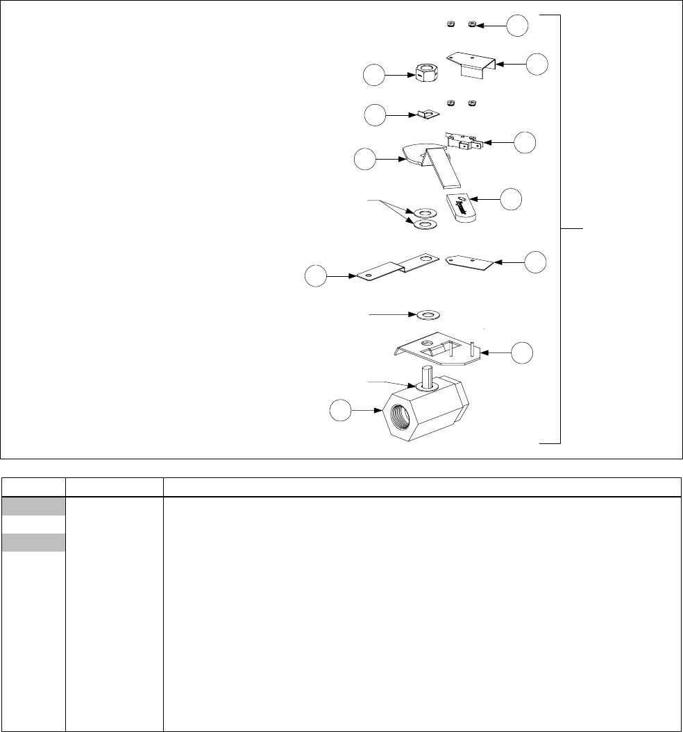
2-33
2.12.4 FMH50 Full Vat (1¼-inch) Valve Assembly
NOTES: Compression washers must
be turned face to face and lock nut
(Item 5) must be torqued to 80 ± 10
inch-pounds.
Item 11 does not come with assembly
806-8791SP.
1
Plastic Washer
(part of Item 1)
11
3
2
7
4
5
8
10
9
806-8791SP
Compression Washers
(part of Item 1)
6
Steel Flat Washer
(part of Item 1)
ITEM PART # COMPONENT
806-8791SP Complete Assembly (does not include Item 11)
1 810-1020 Drain Valve, 1¼-inch NPT Inlet, 1-inch NPT Outlet
810-1018 Drain Valve, 1 ¼-inch, for Hybrid Units, Single FP and Jack in the Box FM.
2 900-2521 Handle, Drain Valve
3 814-0047 Sleeve, Red Valve Handle
4 900-2936 Retainer, ½-inch Nut
5 809-0540 Nut, 2-way Lock, ½–13
6 806-8137 Bracket, Drain Valve Microswitch
7 816-0220 Insulation, RF Switch
8 807-2103 Microswitch, Lever Activated
9 900-2841 Cover, Drain Safety Switch
10 826-1366 Nut, Keps, 4–40, w/external teeth (Pkg. of 25)
11 900-2354 Bracket, Full Vat Drain Valve

2-34
2.12.5 FPH50 Dual Vat (1-Inch X 1¼-inch) Valve Assemblies
3
1 2
4
Steel Flat Washer
(part of Item 4) 6
5
88
Compression
Washers
(part of Item 4)
17
14 99
10
7
7
Plastic Washer
(part of Item 4)
11
12
13
14
15
16
18
19
20
Plastic Washer
(part of Item 4)
NOTE: Compression
washers must be turned
face to face and lock nut
(Item 16) must be torqued
to 60 ± 10 inch-pounds.
21
ITEM PART # COMPONENT
1 806-6400SP Complete Assembly, Left (for CE, use 806-6609SP)
2 806-6401SP Complete Assembly, Right (for CE, use 806-6608SP)
3 816-0135 O-Ring, Drain Valve, 1”
4 810-1114 Drain Valve, 1¼-inch NPT Inlet, 1-inch O-Ring Outlet, ⅜-inch Stem
5 106-2671 Bracket, Drain Valve, Microswitch, Left
6 106-2672 Bracket, Drain Valve, Microswitch, Right
7 900-2355 Bracket, Drain Valve, 1-inch
8 810-1165 Washer, Teflon
10 201-3916 Handle, Drain Valve, Left
11 200-4304 Handle, Drain Valve, Right
12 201-3985 Handle, Drain Valve, Left (replaces Item 10 in 806-6609SP)
13 200-4305 Handle, Drain Valve, Right (replaces Item 11 in 806-6608SP)
14 814-0047 Sleeve, Red Valve Handle
15 900-2934 Retainer, ⅜-inch Nut
16 809-0539 Nut, 2-way Lock, ⅜ –16
17 816-0220 Insulation, RF Switch
18 807-2103 Microswitch, Lever Activated
19 826-1366 Nut, Keps, 4–40, w/external teeth (Pkg. of 25)
20 901-2348 Cover, Drain Safety Switch Left
21 902-2348 Cover, Drain Safety Switch Right
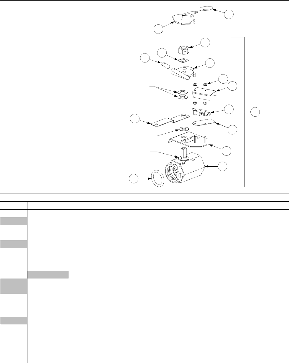
2-35
2.12.6 FPH50 Full Vat (1¼-inch) Valve Assemblies
Compression Washers
(part of Item 1)
Steel Flat Washer
(part of Item 1)
2
3
1
Plastic Washer
(part of Item 1) 4
5
6
7
8
9
10
11
12
13
14
15
NOTE: Compression
washers must be turned
face to face and lock nut
(Item 13) must be torqued
to 80 ± 10 inch-pounds.
ITEM PART # COMPONENT
1 806-6373SP Complete Assembly (for CE, use 806-6610SP)
806-6054 Valve Assembly, 1 ¼-inch Left Single FP
2 816-0135 O-Ring, Drain Valve, 1¼-inch I.D.
3 810-1018 Drain Valve, 1¼-inch NPT Inlet, 1-inch O-Ring Outlet, ½-inch Stem, FV
810-1020 Drain Valve, 1 ¼-inch NPT Inlet, 1-inch O-Ring Outlet, Single FP
4 806-8137 Bracket, Drain Valve, Microswitch
5 816-0220 Insulation, RF Switch
6 807-2103 Microswitch
7Cover, Drain Safety Switch
900-2841 Used w/806-6373SP (Item 1)
901-2348 Replaces 900-2841 in 806-6610SP)
8 826-1366 Nut, Keps, 4–40, w/external teeth (Pkg. of 25)
9 900-2354 Bracket, Drain Valve, 1¼-inch
10 823-2371 Handle, Drain Valve (used w/806-6373SP) (replaced with 900-2609)
823-2066 Handle, Drain Valve Single FP
11 810-0677 Grip, Plastic Handle
12 900-2936 Retainer, FV Drain Valve Nut
13 809-0540 Nut, 2-way Lock, ½–13 (replaces nut that comes with 810-1018)
14 900-2609 Handle, Drain Valve (replaces Item 10 in 806-6610SP)
15 814-0047 Sleeve, Red Valve Handle

2-36
2.13 Filtration Systems and Component Parts (Other than Drain Components)
2.13.1 Filter Magic II/Single FootPrint III Filter Pan Assembly
A
12
7
8
11
13
10
9
Detail of fitting on
outside bottom
of inner pan.
B
1
9
4
2
6
8
7
12
3
11
5
10
13
ITEM PART # COMPONENT
A 806-9255SP One-Piece Filter Pan Assembly (Items 7, 8, 11, 12, and 13) used also on
Single FP
106-0089SP One-Piece Filter Pan Assembly with Magnasol Leaf (Carl’s Jr.)
823-2751SP One-Piece Pan Only
B 806-6093SP Two-Piece Pan Assembly, Complete (Unique components are listed below.)
1 823-1360SP Outer Pan Assembly
2 823-1731SP Inner Pan Assembly
3 823-1361 Base, Filter Pan Assembly
4 824-0291 Cover, Suction Tube
5 910-1350 Clamp, Suction Tube
6 816-0117 O-Ring, .609 OD
* 806-4373 Heater Strip Assembly
* 811-0861 Insulation, Foam #9812
* 811-0746 Tape, Aluminum (50-yard (46m) roll)
Components Used on Both Designs
7 810-2807 Caster, Rigid 2-inch
8 810-2805 Caster, Swivel 2-inch Filter Pan
9 823-1930 Cover, Drain Pan
806-9079SP Cover, Drain Pan Assy. W/ Handle
10 824-0416 Crumb Screen
11 810-1406 Hold Down Ring Assembly
12 900-8827 SanaGrid Filter Screen
13 810-0180 Handle, Filter Pan
* 803-0170 Paper, Filter (100 sheets) 16 ½” x 25 ¾”
* 803-0002 Powder, Filter (80- individual packs)
* Not illustrated
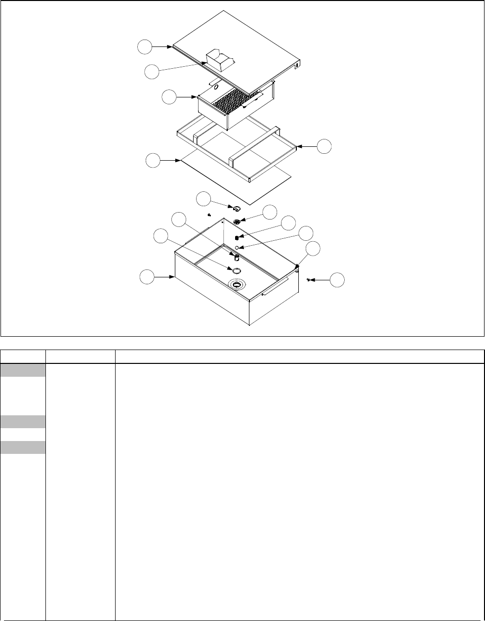
2-37
2.13.2 FootPrint III Filter Pan Assembly
1
12
2
3
4
5
6
7
8
9
10
11
14
13
ITEM PART # COMPONENT
806-5618SP Pan Assembly, Complete (Items 1 through 11)
1 823-2027 Cover
2 810-1408 Hold Down Ring 13 ¾” x 20 ⅝”
3 900-8827 SanaGrid Filter Screen 12” x 19 ½” / 30.5cm x 49.5cm (without holes)
806-8551SP Inner Pan Assembly w/ check valve
4 823-1979SP Pan
826-1490 Kit, Filter Pan Check Valve Service (consists of Items 5 through 10)
5 810-1387 Retainer, Check Valve
6 900-5448 Strain Plate, Check Valve
7 810-0946 Spring, Check Valve
8 810-0948 Ball, Check Valve
9 810-1388 Tube, Check Valve
10 816-0597 O-Ring, Check Valve
11 809-0422 Screw, Shoulder
12 824-0430 Crumb Screen
13 809-0028 Nut, 10-32
14 910-4816 Splashguard, Filter Lid
* 826-1486 Kit, Swivel for FPIII Service
* 803-0170 Paper, Filter (100 sheets) 16 ½” x 25 ¾”
* 803-0002 Powder, Filter (80 individual packs)
* Not illustrated
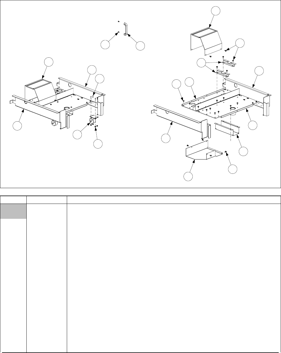
2-38
2.13.3 FootPrint III Filter Base Assemblies
1
1
22
10
10
9
3
4
11
12
6
7
8
5
5
5
13 14
ITEM PART # COMPONENT
806-9619SP Base Assembly w/o Casters (Items 1- 5)
806-5954SP Base Assembly w/Casters (Items 1-8)
1 201-3768 Frame, Left Side
2 202-3768 Frame, Right Side
3 900-5396 Support, Filter Motor
4 823-2289 Support, Filter Pan
5 826-1374 Screw, #10 X ½-inch Hex Washer Head (Pkg. of 25)
6 810-2805 Caster, Swivel 2-inch filter pan
7 809-0021 Stud, 10-32 X ⅝-inch Stainless Steel
8 826-1376 Nut, Keps 10-32 Hex (Pkg. of 10)
9 900-1949 Standoff, Filter Wiring Box (see Page 1-55 for Filter Wiring Box)
10 900-5477 Cover, Motor (August 1997 and later)
* 824-0558 Cover, Motor (Before August 1997)
11 900-7557 Cover, Suction Tube
12 900-9634 Cover, Rear Plumbing (used after August 1999)
13 826-1360 Screw, Handle (Pkg. of 25)
14 810-0180 Handle, Plated Diecast Metal (for use on bases built before August 1997)
* 826-1677 Kit, Pin Extender FPIII
* KIT1013SP Kit, FPH50 Filter Module FPIII
* KIT3258SP Kit, FPH50 Filter FPIII w/out caster kit
* Not illustrated.
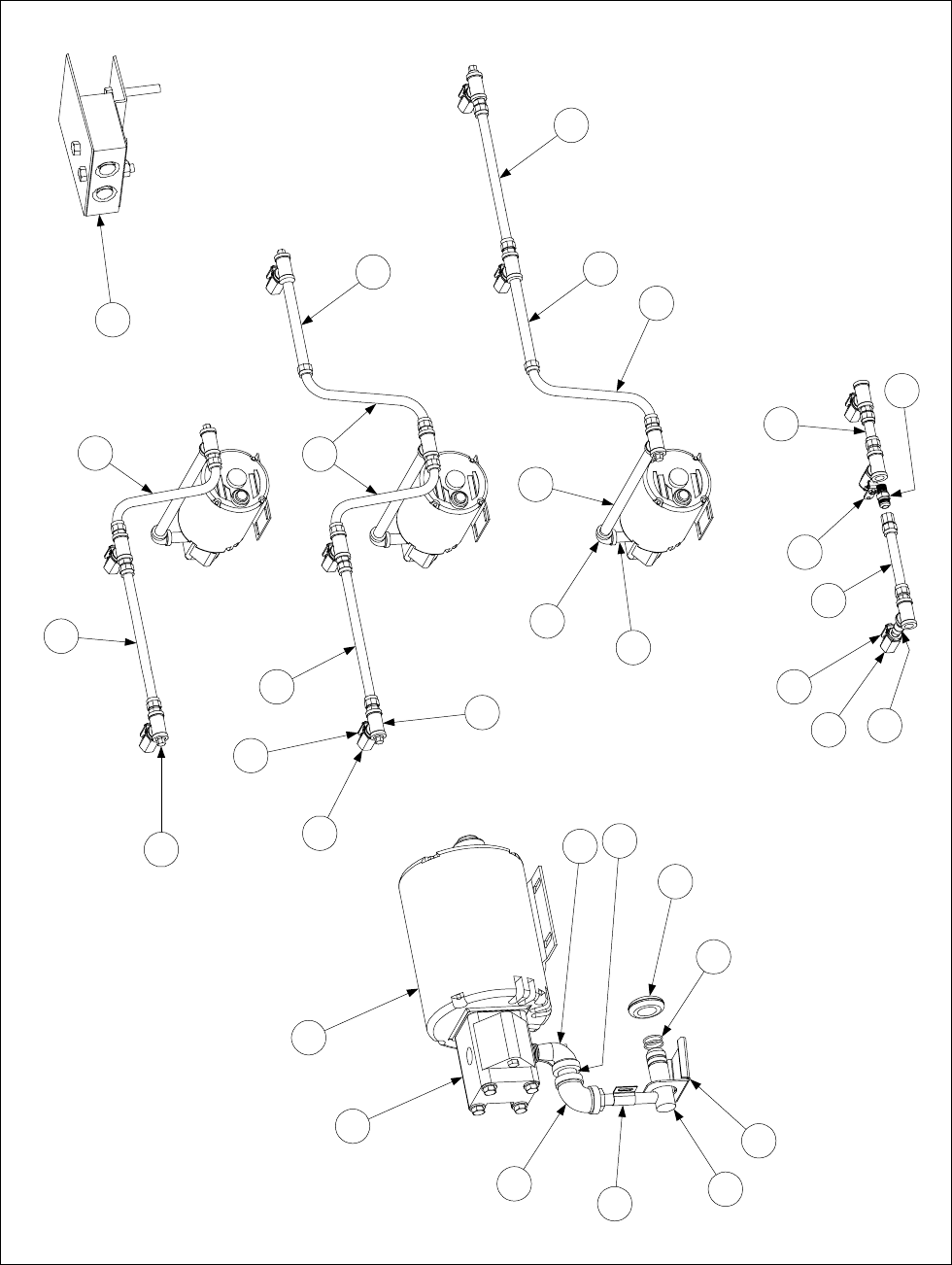
2-39
2.13.4 Filter Magic Oil Return Plumbing Components (Including Pump & Motors)
Typical Dual (Split)
Vat Configuration
Typical Full Vat
Configurations
8
8
16
17
18
19
13
10
11
NOTE: If the filter is to the left
of a dual vat unit, use the 3.5-
inch nipple (813-0117) in place
of the 9-inch nipple (Item 9).
6
7
8
8
9
11
3
45
8
9
8
23
Item shown disproportionately
large for clarity.
Detail of Motor, Pump, and
Disconnect Components
1
2
4
12
14 15
13
20
21
22
10

2-40
ITEM PART # COMPONENT
1Pump Motor
826-1712 100-120 VAC 50/60Hz (with gasket 816-0093)
826-1756 208 VAC 50/60 Hz (with gasket 816-0093)
826-1270 230-250 VAC 50/60 Hz (with gasket 816-0093)
* 807-11973 Pump Service Kit (gasket, shaft seal, and two O-rings)
* 806-6728SP Pump Wiring Assembly (this component is furnished with above motors)
2 826-1264 Pump, 4 GPM (15 LPM) (with gasket 816-0093 and mounting screws)
13 826-1360 Screw, Handle (Pkg. of 25)
14 810-0180 Handle, Plated Diecast Metal (for use on bases built before August 1997)
5 813-0368 Nipple, ½-inch x 16-inch
6 813-0156 Pipe Plug, ½-inch
7 813-0003 Tee, ½-inch
8 810-1057 Flexline, ⅝ -inch x 13-inch Oil Return (two female ends)
9 813-0275 Nipple, ½-inch x 9-inch
10 810-0278 Valve, ½-inch Ball
11 902-0883 Handle, Right Valve
901-0883 Handle, Left Valve
12 813-0165 Elbow, ½-inch x 90º Street
13 813-0022 Nipple, ½-inch Close
14 823-1356 Disconnect Fitting Male
15 826-1392 O-Ring (Pkg. of 5)
16 901-0883 Handle, Left Dual-Vat Valve
17 810-1159 Flexline, 5-inch Oil Return (two female ends)
18 810-1668 Adapter, ⅝ -inch Female to ½-inch Female (used with Item 17)
* 810-1669 Adapter, ⅝ -inch Female to ½-inch Male (used with Item 17)
* 826-1890 Flexline Kit, 7-Inch Oil Return (Items 17, 18, and 810-1669)
19 810-1160 Flexline, 3-inch Oil Return (two female ends)
20 816-0102 Grommet, Oil Diverter
21 900-1472 Diverter, Oil
22 910-1627 Bracket, Male Disconnect Support
23 806-4694SP Contactor Block Assembly
* 813-0117 Nipple, ¾-inch x 3½-inch
* 807-1600 Thermal Switch, 100-120V Baldor Motors
* 807-1601 Thermal Switch, 200-250V Baldor Motors
* 807-1598 Thermal Switch, 100-120V Magnatek Motors
* 807-1599 Thermal Switch, 200-250V Magnatek Motors
* 810-1062 Wiring Harness, Controller to Filter
* 806-7020SP Heater Assembly Strip, 120 VAC 50W, 70-inch
807-1408 Heater Strip Only, 120 VAC 50W, 70-inch
* 806-7021SP Heater Assembly Strip, 250 VAC 90W, 70-inch
807-2348 Heater Strip Only, 250 VAC 90W, 70-inch
* 811-0861 Foam Tape Insulation 3-inch wide (by the foot)
* 811-0746 Tape, Aluminum (2-inch x 50-yard (46m) roll)
* Not illustrated

2-41
2.13.5 FootPrint III Filter Motors and Pump Plumbing Components
Standard FP III Configuration (August 1997 and Later)
7
10
12
13
3
2
11
20
14
15
16
9
8
FPH150 Configuration
4
2
5
4
1
6
Standard FP III Configuration (Prior to August 1997)
1
10
2
14
19
17
5
18

2-42
ITEM PART # COMPONENT
1Motor and Gasket Kits
826-1712 100-120VAC 50/60 Hz (with gasket 816-0093)
826-1756 208 VAC 50/60 Hz (with gasket 816-0093)
826-1270 230-250VAC 50/60 Hz (with gasket 816-0093)
* 807-11973 Pump Service Kit (gasket, shaft seal, and two O-rings)
2 826-1264 Pump, 4GPM (15LPM) (includes gasket 816-0093 and mounting screws)
3 807-2484 Valve, Solenoid Vent (145 ohms)
4 810-1160 Flexline, 3-inch Oil Return (two female ends)
5 813-0062 Elbow, ½-inch x 90º
6 813-0022 Nipple, ½-inch x close
7 810-1404 Flexline, Oil Return (pump to rear manifold)
8 810-1057 Flexline, 13-inch Oil Return (two female ends)
9 810-1373 Flexline, Pump Bypass
10 813-0165 Elbow, ½-inch x 90º Street
11 813-0265 Nipple, ½-inch x 2½-inch
12 813-0537 Nipple, ¼-inch x 2-inch
13 813-0543 Elbow, ¼-inch x 90º Street
14 813-0460 Nipple, ½-inch x 3-inch
15 813-0331 Elbow, ½-inch 3-way
16 813-0304 Bushing, ½-inch to ¼-inch Reducer
17 810-1159 Flexline, 5-inch Oil Return (two female ends)
18 Hose, Heated Oil Return
810-0945 120VAC
810-1037 202-250VAC
19 900-1958 Support, Oil Return
20 813-0530 Tee, ½-inch x ¼-inch x ½-inch NPT Reducing
* 806-9245SP Pump Heater Strip Assembly, 120VAC, 25W, 36-inch
* 807-1420 Pump Heater Strip, 120VAC, 25W, 36-inch
* 806-8004SP Pump Heater Strip Assembly, 120VAC, 40W, 56-inch
807-1472 Pump Heater Strip, 120VAC, 40W, 56-inch
* 806-7755SP Pump Heater Strip Assembly, 120VAC, 100W, 72-inch
* 807-2304 Pump Heater Strip, 120VAC, 100W, 72-inch
* 807-1408 Pump Heater Strip, 120VAC, 50W, 70-inch
* 826-1668 Heat Tape Kit, 120VAC 20w
* 826-1669 Heat Tape Kit, 208-250VAC 20w
* 816-0093 Gasket, Pump Motor
* 807-1600 Thermal Switch, 100-120V Baldor Motors
* 807-1601 Thermal Switch, 200-250V Baldor Motors
* 807-1598 Thermal Switch, 100-120V Magnatek Motors
* 807-1599 Thermal Switch, 200-250V Magnatek Motors
* 806-6728SP Pump Wiring Assembly, FPH150
* 810-1062 Wiring Harness, Controller to Filter
* 811-0861 Foam Tape Insulation 3-inch wide (by the foot)
* 811-0746 Tape, Aluminum (2-inch x 50-yard (46m) roll)
* Not illustrated
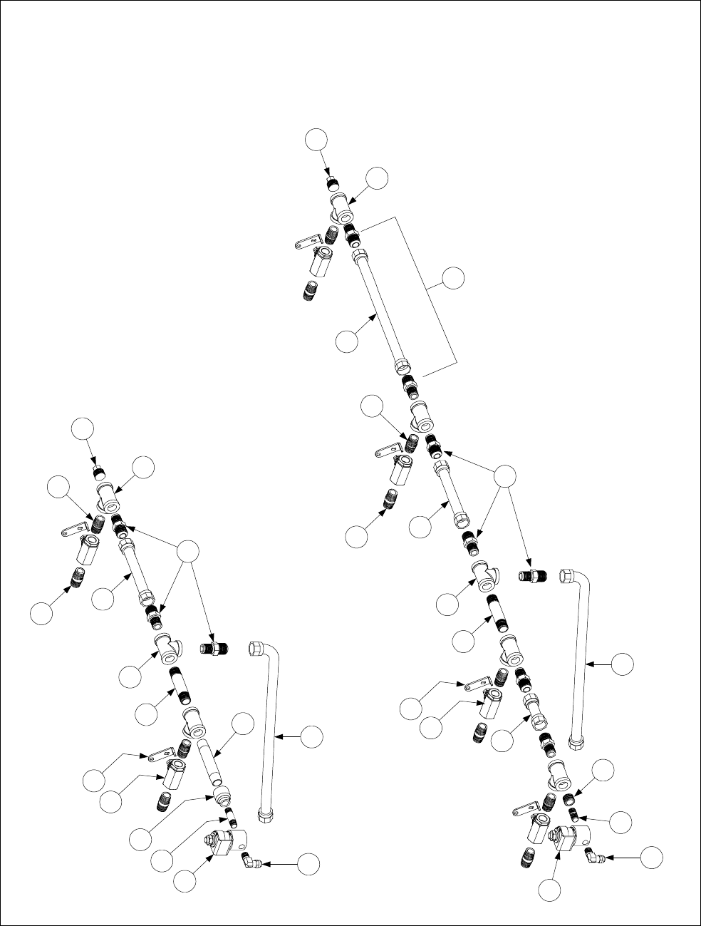
2-43
2.13.6 FootPrint III with Power Shower Oil Return Plumbing Components
TYPICAL FOOTPRINT III
OIL RETURN PLUMBING
CONFIGURATIONS
NOTE: Fryers manufactured between August 1997 and
April 1998 had a one-piece welded oil return manifold.
These manifolds have been discontinued and are no
longer available. The fittings and flexlines shown in this
illustration must be used to replace failed manifolds.
1
2
2
34
4
5
6
7
11
15
9
8
7
10
13
14
12
7
5
6
15
9
87
11 17
16
18
FPH250
10
FPH350 with Dual
Vat on Left
NOTE: The assemblies in this illustration represent only
two of the many different configurations used. However,
the individual components shown are used to create all
the other configurations.
1
3
19
20

2-44
ITEM PART # COMPONENT
1 807-2484 Valve, Solenoid Vent
2 810-0278 Valve, ½-inch NPT Ball
3 810-1372 Fitting, ¼-inch NPT x 90º
4 810-1069 Flexline, Oil Return, 29.5-inch
5 810-1668 Adapter, ½-inch NPT Male (converts female to male)
6 810-1680 Flexline, Oil Return, 6.5-inch
7 813-0003 Tee, ½-inch NPT
8 813-0022 Nipple, ½-inch NPT x Close
9 813-0087 Nipple, ½-inch NPT x 1.5-inch
10 813-0156 Plug, ½-inch NPT
11 813-0247 Nipple, ½-inch NPT x 3.5-inch
12 813-0251 Nipple, ½-inch NPT x 4.5-inch
13 813-0537 Nipple, ¼-inch NPT x 2-inch
14 813-0555 Reducer, ½-inch to ¼-inch NPT
15 902-0883 Handle, Oil Return Valve (Right)
901-0883 Handle, Oil Return Valve (Left)
16 810-1057 Flexline, Oil Return, 13.0-inch
17 806-9437SP Flexline Assembly, Oil Return, 15.5-inch (2 of Item 5 plus Item 16)
18 810-1160 Flexline, Oil Return, 3.0-inch
19 813-0304 Reducer Bushing, ½-inch to ¼-inch NPT
20 813-0016 Nipple, ¼-inch NPT x Close
* 826-1720 Vent Tube, Teflon, ⅜-inch O.D. x 24-inches
* 811-0932 Vent Tube, Teflon, ⅜-inch O.D. per foot
* 816-0224 Insulation, Rubber 3-inch x 6-inch
NOTE: The following Oil Return Flexlines and miscellaneous components may also be used in some
specially configured units. When ordering a flexline, it is recommended that the line be measured (from
outside of flare fitting to outside of flare fitting) to ensure the correct item is ordered.
* 810-1160 Flexline, Oil Return, 3.0-inch
* 810-1339 Flexline, Oil Return, 4.5-inch
* 810-1159 Flexline, Oil Return, 5.0-inch
* 810-1067 Flexline, Oil Return, 8.5-inch
* 810-1043 Flexline, Oil Return, 9.5-inch
* 810-1055 Flexline, Oil Return, 11.5-inch
* 810-1369 Flexline, Oil Return, 17.5-inch
* 810-1068 Flexline, Oil Return, 21.5-inch
* 810-1069 Flexline, Oil Return, 29.5 inch
* 810-1056 Flexline, Oil Return, 52.5-inch
* 810-1669 Adapter, ½-inch NPT Female (converts male to female)
* 901-0883 Handle, Oil Return Valve (Left) (mirror of Item 15 above)
* 902-0883 Handle, Oil Return Valve (Right)
* Not illustrated
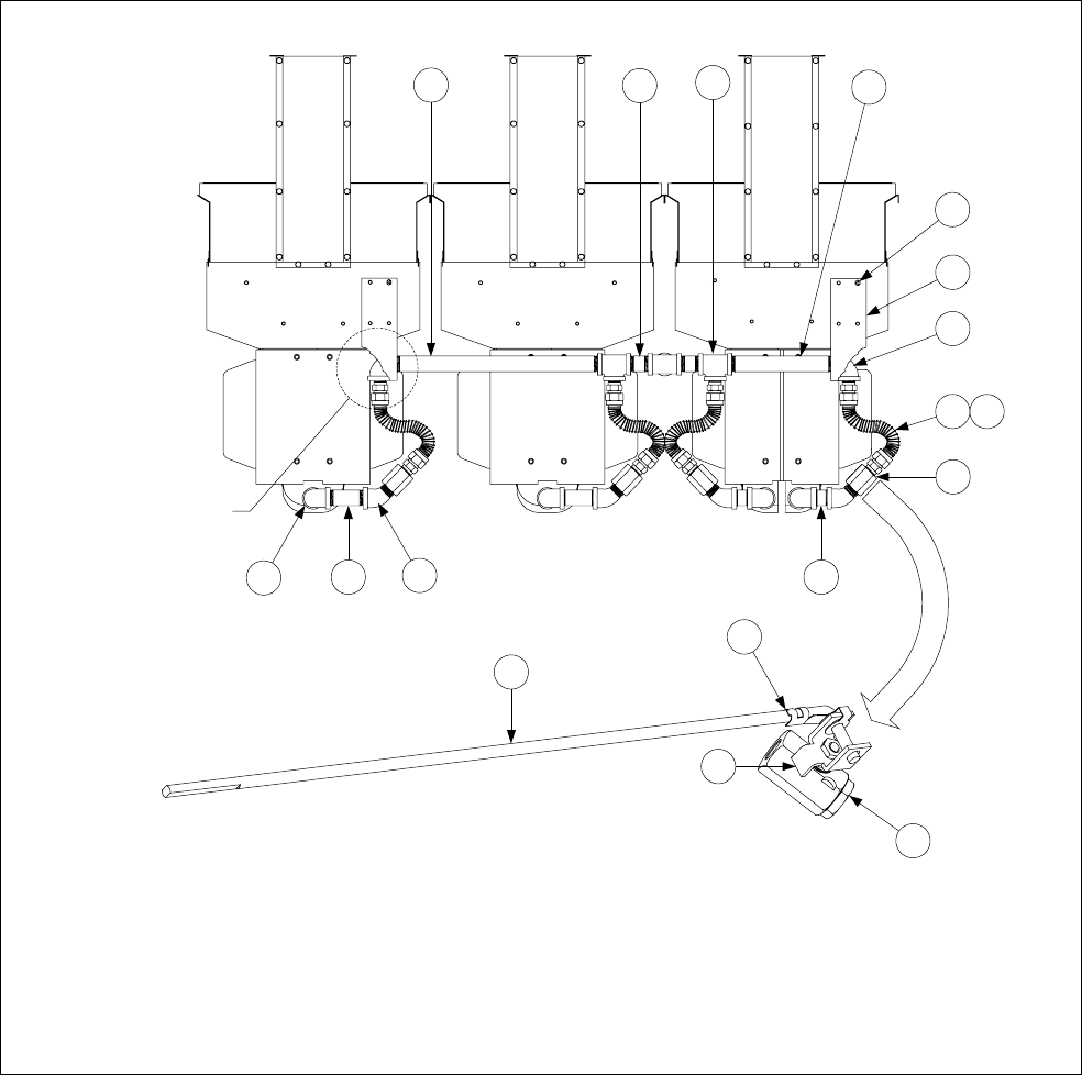
2-45
2.13.7 FootPrint III with Rear Flush Oil Return Plumbing Components, Standard
FPH350-2L Rear Flush (Typical)
See Page 2-47 for KFCH50 Rear Flush Oil Return Components.
See Page 2-48 for Oil Return Handle Components.
13 12 11 10
9
8
7
617
5
4
3
2
1
14
15
16
5
Hanger shown
cut away to
reveal elbow.

2-46
ITEM PART # COMPONENT
1 813-0165 Elbow, ½-inch x 90º Street
2 813-0265 Nipple, ½-inch x 2½-inch
3 813-0342 Elbow, ½-inch x 45º Street
4 813-0087 Nipple, ½-inch x 1½-inch
5 810-0278 Valve, ½-inch Ball
* 810-1003 Valve, ½-inch 180º 3-way Ball
6 810-1067 Flexline, 8.5-inch Oil Return
7 813-0062 Elbow, ½-inch x 90º
8 900-2783 Hanger, Rear Flush
9 809-0417 Nut, ¼-20 Serrated Flange
10 813-0320 Nipple, ½-inch x 2-inch
11 813-0003 Tee, ½-inch
12 813-0298 Nipple, ½-inch x 2-inch
13 813-0360 Nipple, ½-inch x 14-inch
14 810-1209 Shaft, Rear Flush Valve
15 809-0601 Clip, Rod End Clevis
16 901-2772 Handle, Left Rear Flush Valve
* 902-2722 Handle, Right Rear Flush Valve
17 810-1668 Adapter, ½-inch NPT Male (converts female to male)
* 810-1056 Flexline, 56-inch Oil Return
*Strip, Heater
806-8065SP 100VAC, 18-inch (46cm), 25 Watt
806-6730SP 100VAC, 56-inch (142cm), 40 Watt
806-5933SP 120VAC, 18-inch (46cm), 25 Watt
806-8004SP 120VAC, 56-inch (142cm), 40 Watt
806-5934SP 200-250VAC, 18-inch (46cm), 25 Watt
806-5932SP 200-250VAC, 36-inch (91 cm), 45 Watt
806-6732SP 200-250VAC, 56-inch (142cm), 70 Watt
* 811-0861 Foam Tape Insulation 3-inch wide (by the foot)
* 811-0746 Tape, Aluminum (50-yard (46m) roll)
* Not illustrated
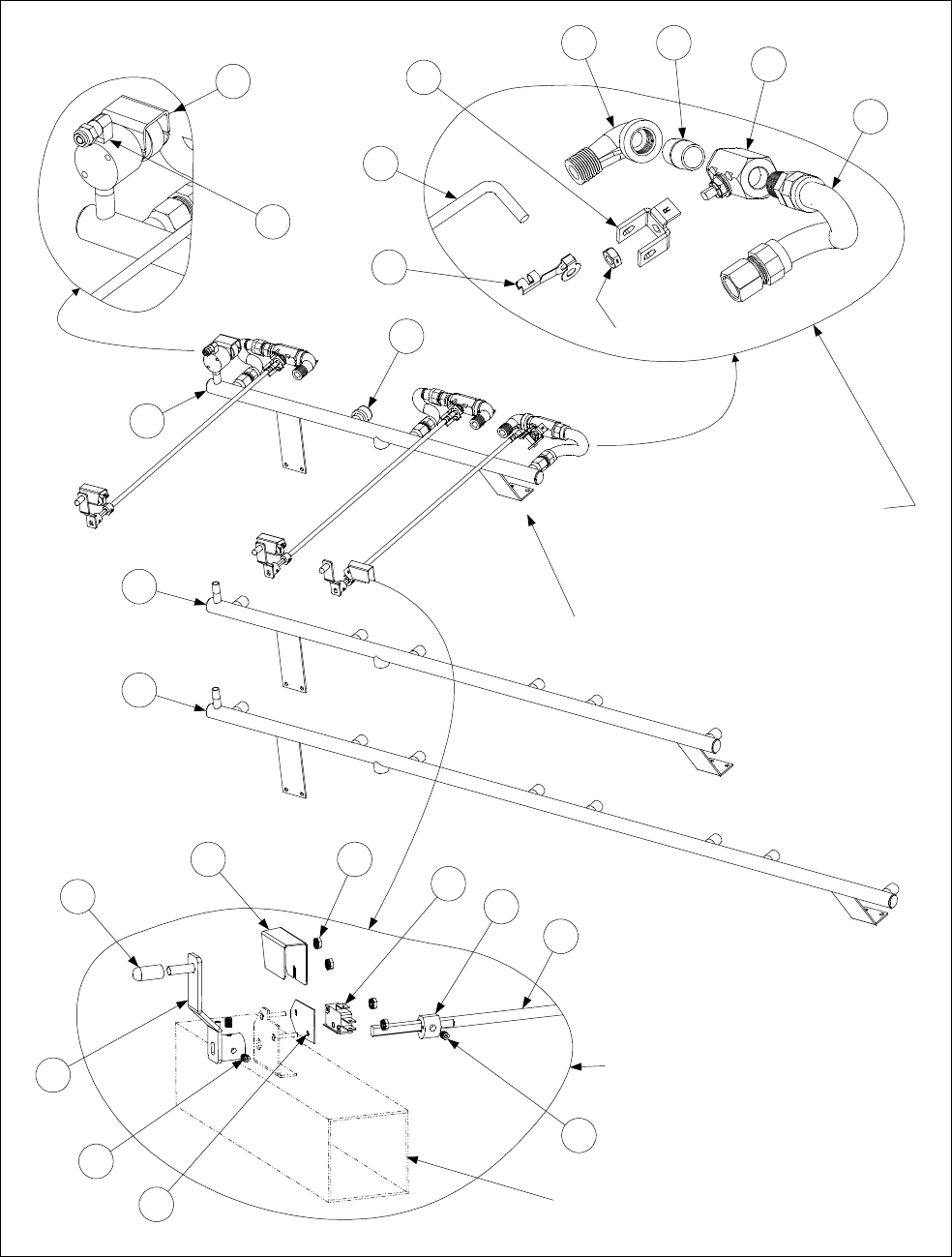
2-47
2.13.8 FootPrint III with Rear Flush Oil Return Plumbing Components, KFC
See Page 2-28 for Square
Drain components
4
14
Right Handle and Switch Assembly
(All components except for Items 4 and 14
are the same for Left Handle and Switch
Assembly)
15
16
17
19
18
18
20
21
Right Oil Return Valve Assembly
(All components except for Items 4 and 5
are the same for Left Oil Return Valve
Assembly)
Nut (furnished
with Item 8)
13
12
11
1
2
3
10
4
5
6 7
8
9
TYPICAL CONFIGURATION
(KFCH250 Full Vat Left /Dual Vat Right
shown)

2-48
ITEM PART # COMPONENT
1 807-2484 Valve, Solenoid Vent
2 810-1372 Elbow, 90º x ¼-inch NPT x ⅜-inch Tube
* 811-0932 Vent Tube, Teflon, ⅜-inch O.D. per foot
3 809-0601 Clip, Rod End Clevis
4Shaft, Rear Flush Valve
810-1767 For use in left oil return valve assemblies (see illustration below).
810-1766 For use in right oil return valve assemblies (see illustration below).
5Handle, Rear Flush Valve
901-2772 For use in left oil return valve assemblies.
902-2772 For use in right oil return valve assemblies.
6 813-0165 Elbow, 90º x ½-inch Street
7 813-0022 Nipple, ½-inch Close
8 810-0278 Valve, ½-inch Ball
* 900-2935 Nut, Oil Return Valve Retainer
* 810-1003 Valve, ½-inch 180º 3-way Ball
9 806-9828SP Flexline Assembly, 9-inch Oil Return
10 813-0469 Cap, ½-inch Pipe
11 810-1360 Manifold, KFCH250 Rear Flush Oil Return
12 810-1357 Manifold, KFCH350 Rear Flush Oil Return
13 810-1378 Manifold, KFCH450 Rear Flush Oil Return
14 Cover, FPH50 Rear Flush Oil Return Microswitch
901-2214 For use in left handle and switch assemblies.
902-2214 For use in right handle and switch assemblies.
15 826-1366 Nut, 4-40 Keps Hex (Pkg. of 25)
16 807-2103 Microswitch
17 810-1186 Cam, Filter System Microswitch
18 826-1377 Setscrew, 10-32 x ¼-inch (Pkg. of 25)
19 816-0220 Insulation, Microswitch
20 Handle, Rear Flush
823-2295 For use in Non-CE applications (see illustration below).
823-2259 For use in CE applications only (see illustration below).
21 812-1253SP Cover, Rear Flush Handle
NOTE: Left and right refer to the fryer as viewed from the front when facing the fryer.
Shaft 810-1767
(Note orientation of flat
and 45° angle to left.)
Shaft 810-1766
(Note orientation of flat
and 45° angle to right.)
Full Vat or
Left Side of Dual Vat Right Side of Dual Vat
Handle 823-2295
(Note orientation of slot)
This handle is used in
non-CE applications.
NOTE: Handles are shown in
Valve OPEN/Filter ON position.
Handle 823-2259
(Note orientation of slot)
This handle is used in
CE applications.
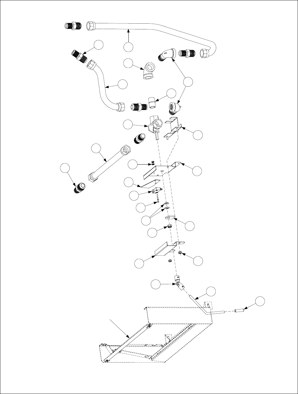
2-49
2.13.9 FPH150-2 Oil Return Plumbing
1
2
3
4
5
6
7
8
9
10
11
12
13
14
15
16
17
18
19
19
20
21
22
Control Panel Assembly 806-6358SP
shown for reference. Assembly
includes Items 20-21.

2-50
ITEM PART # COMPONENT
806-6309SP FPH150-2 Oil Return Plumbing Assembly (Items 1-19)
1 826-1376 Nut, 10-32 Keps (Pkg. of 10)
2 900-2110 Cover, Switch
3 809-0056 Locknut, 5/16-inch x 24 Nylon
4 910-2311 Switch, Actuator
5 809-0519 Washer, 5/16 Spring (2 each)
6 826-1359 Screw, 4-40 x ¾-inch (Pkg. of 10)
7 807-2104 Microswitch, Roller-activated
8 812-0442 Insulation, Microswitch
9 900-2268 Mount, Microswitch
10 826-1366 Nut, 4-40 Keps (Pkg. of 25)
11 806-8342 Bracket, Oil Return Valve
12 810-1055 Flexline, Oil Return, 11.5-inch
13 810-1003 Valve, ½-inch NPT 3-way Ball
14 813-0022 Nipple, ½-inch NPT x Close
15 813-0062 Elbow, ½-inch x 90º
16 813-0165 Elbow, Street, ½-inch x 90º
17 810-1068 Flexline, Oil Return, 21.5-inch
18 810-1067 Flexline, Oil Return, 8.5-inch
19 810-1668 Adapter, ½-inch NPT Male (converts female to male)
806-6358 FPH150-2 Control Panel Assembly, Complete (including Items 20-22)
20 810-0677 Grip, Oil Return Handle
21 910-2312 Handle (Rod), Oil Return
22 810-1115 U-Joint
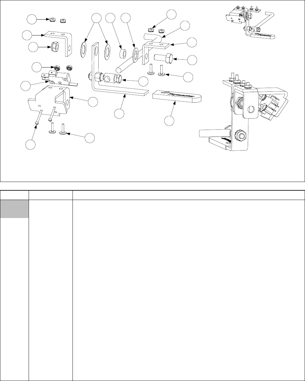
2-51
2.13.10 Oil Return Handle Assembly, Filter Magic & Standard FootPrint III
Handle and switch assembly is shown in right-hand configuration (806-3470SP). Left-hand
configuration (806-3471SP) is mirror image of 806-3470SP using same components. Oil
return valve rod (Item 16) IS NOT a component of either assembly.
Detail of Switch
Mounting
9
13
3
8
2
1
4
10
14
15
711 69
13
10
4
12
16
ITEM PART # COMPONENT
806-3470SP Handle and Switch Assembly, Right (Items 1-15)
806-3471SP Handle and Switch Assembly, Left (Items 1-15)
1 200-0821 Bracket, Handle and Microswitch
2 807-2103 Microswitch
3 809-0056 Nut, 5/16 – 24, Hex Head, Nylon Lock
4 809-0103 Screw, 8-32 x ½” Slotted Truss Head
5 809-0142 Screw, 5/16 – 24 x ¾” Hex Head
6 809-0200 Washer, Flat
7 826-1381 Washer, Nylatron (Pkg of 10)
8 826-1366 Nut, 4-40 Hex Keps (Pkg of 25)
9 809-0247 Nut, 8-32 Hex Keps
10 826-1359 Screw, 4-40 x ¾” Slot Head (Pkg of 25)
11 810-0220 Spacer, Tubular, .493 OD
12 810-0285 Swivel Fitting, Oil Return Valve Linkage
13 810-1999 Bracket, Valve Handle
14 920-0831 Handle, Oil Return
15 814-0047 Sleeve, Handle
16 910-0832 Rod, Oil Return Valve (must be ordered separately from assemblies)
* 810-0278 Valve, Ball ½-inch
* 826-1878 Kit, Brace Filter
* Not illustrated

2-52
2.13.11 Power Shower Assemblies (All Models)
2
1
3
4
ITEM PART # COMPONENT
806-4442SP Power Shower Assembly, Full Vat, Complete
806-4476SP Power Shower Assembly, Dual Vat, Complete
1 814-0001 Grip, Handle
2 809-0415 Screw, Cleanout
3 826-1390 Seal (Gasket) (pkg of 5)
4 826-1344 O-Ring (pkg of 5)

2-53
2.13.12 Oil Disposal Systems Plumbing
806-9087SP
806-9330SP
23a
17
5
6
25
4
26
2
29
30
17
23a
27
21
19
1
20
Detail of Item 1
98
14
13
12
10
11
28
31
32
18
17
15
16
19
1
20
21
7
4
22
3
2
These components
are part of Item 13.
1
17
23b
30
33
34
22
2
806-9109SP
810-0490

2-54
ITEM PART # COMPONENT
806-9087SP Oil Disposal Plumbing Assembly (side discharge configuration)
806-9330SP Oil Disposal Plumbing Assembly (rear discharge configuration) H50 oil Return
1 806-8762SP Ball Valve with Microswitch Assembly
*WIR0315SP Wire Assembly, Ball Valve Microswitch
2 810-0487 Quick Disconnect, ½-inch Male
3 809-0454 Nut, ½-inch Conduit (mounts between Item 2 and Item 6)
4 826-1374 Screw, #10 x ½-inch Hex Head (Pkg of 25)
5 910-8809 Bracket, Oil Disposal Mounting (rear connection configuration)
6 809-0951 Clamp, Hose (limits movement of plumbing through mounting bracket)
7 910-8085 Bracket, Oil Disposal Mounting (side connection configuration)
8 814-0047 Sleeve, Valve Handle
9 900-5953 Handle, Oil Disposal Valve
10 809-0237 Nut, 4-40 Hex Head Keps
11 807-2103 Microswitch, Roller Activated
12 900-8057 Bracket, Microswitch Mounting
13 810-0278 Valve, ½-inch Gemini (without handle)
* 900-2935 Nut, Oil Return Valve Retainer
14 809-0354 Screw, 4-40 x ¾-inch Round Head
15 810-1680 Flexline, 6.5-inch Oil Return
16 810-1668 Adapter, ½-inch NPT Male (converts female to male)
17 813-0003 Tee, ½-inch x ½-inch x ½-inch
18 813-0251 Nipple, ½-inch x 5-inch
19 813-0320 Nipple, ½-inch x 8-inch
20 813-0275 Nipple, ½-inch x 9-inch
21 813-0062 Elbow, ½-inch x 90º
22 813-0022 Nipple, ½-inch x Close
23a 813-0156 Plug, ½-inch Pipe Hex Head
23b 813-0463 Plug, ½-inch Pipe Counter Sink
24 813-0087 Nipple, ½-inch x 1½-inch
25 813-0541 Nipple, ½-inch x 25½-inch
26 813-0265 Nipple, ½-inch x 2½-inch
27 813-0298 Nipple, ½-inch x 2-inch
28** 806-9178SP Hose Assembly, Oil Disposal (Items 29-32) Sonic
29 810-0490 Quick Disconnect Fitting, ½-inch Female
30 813-0165 Elbow, ½-inch x ½-inch 90º Street
31 810-1434 Hose Assembly, 66-inch Oil
32 810-0667 Check Valve, ½-inch
33 813-0037 Coupling, ½ NPT x 1-⅛
34 813-0360 Nipple, ½ x 14.00-inch NPT BM Pipe
* KIT3578SP Kit, Oil Return FPH50 (Sonic)
* 806-9109SP Kit, Oil Return FM
* WIR0315SP Wire Assembly Sonic Oil Disposal
** Not illustrated.
** Item 28 is NOT a component of either 806-9087SP or 806-9330SP.
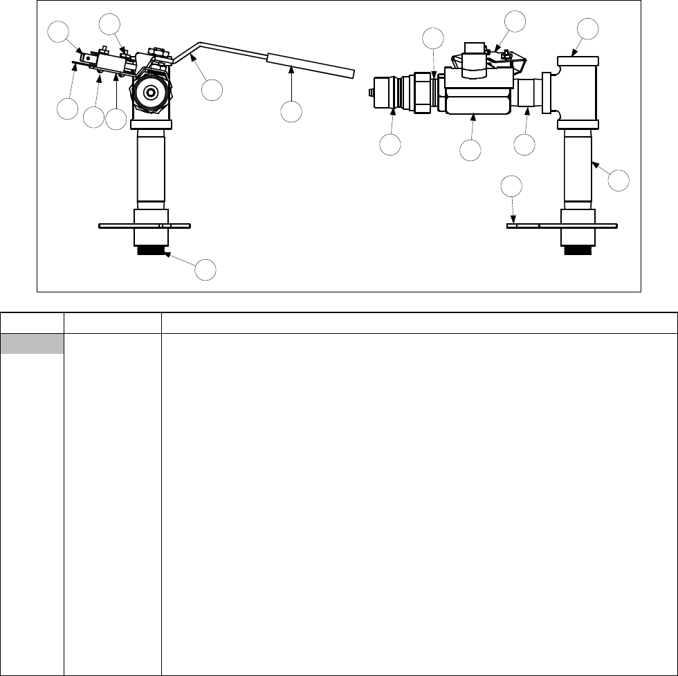
2-55
2.13.13 Assembly Wand Plumbing Japan
12
12 314
10
15
11
549
13 8
6
16
7
ITEM PART # COMPONENT
806-9700SP Plumbing Assembly, Japan Wand
1 807-2103 Switch, CE Micro
2 826-1366 Nut, 4-40 (Pkg. of 25)
3 826-1359 Screw, 4-40 x ¾ (Pkg. of 25)
4 810-0278 Valve, ½-inch Ball
5 810-0487 Coupling, Male
6 813-0003 Tee, ½ x ½ x ½
7 813-0002 Nipple, ½ x Close NPT
8 813-0156 Plug, ½ NPT
9 813-0247 Nipple, ½ x 3½-inch NPT
10 813-0298 Nipple, ½ x 2-inch NPT
11 814-0047 Sleeve, Handle Valve Red w/ Logo
12 816-0220 Insulation, RF Switch
13 823-2029 Support, Oil Return
14 900-1862 Bracket, Microswitch Mounting ½ Ball Valve
15 900-2839 Handle, Valve Wand Japan
16 900-2849 Cover, Wand Microswitch Japan
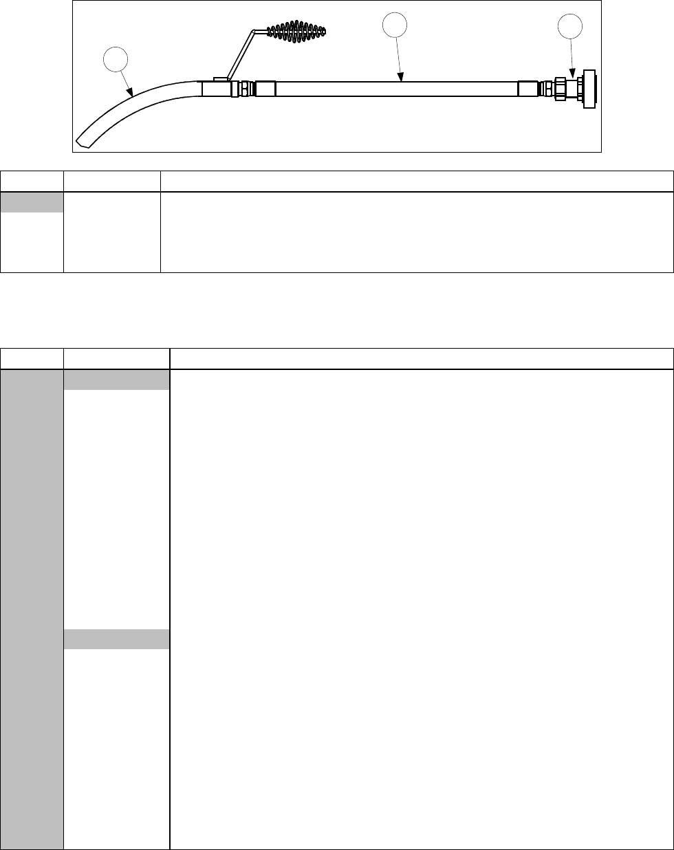
2-56
2.13.14 Oil Disposal Wand Assembly
3
2
1
ITEM PART # COMPONENT
806-7459 Assembly, Oil Disposal Wand
1 810-0603 Wand, FB Filter
2 810-1471 Hose, 24 FPH50 Japan
3 810-0490 Quick Disconnect, ¼-inch Female
2.14 Frypot Assemblies and Component Parts
2.14.1 Replacement Frypots and Frypot Insulation Kits
ITEM PART # COMPONENT
Replacement Frypot Assemblies, Complete
106-1026 Full Vat, Non-Filter, Natural Gas
106-1049SP Full Vat, Power Shower & Rear Flush, Natural Gas
106-1050SP Full Vat, Power Shower & Rear Flush, Propane Gas
106-1047SP Full Vat, Power Shower, w/Four Holes, Natural Gas* Replaced by 106-1049SP
106-1048SP Full Vat, Power Shower, w/Four Holes, Propane Gas*Replaced by 106-1050SP
106-1043SP Full Vat, Power Shower, Manufactured Gas
106-1058 Dual Vat, Power Shower, Natural Gas
106-1079SP Dual Vat, Power Shower & Rear Flush, Natural Gas
106-1080SP Dual Vat, Power Shower & Rear Flush, Propane Gas
106-1066SP Dual Vat, Power Shower, Manufactured Gas
106-1070SP Dual Vat, Rear Flush (KFC, Natural Gas)
106-1071SP Dual Vat, Rear Flush (KFC, Propane Gas)
Replacement Insulation Kits
826-0929 Full Vat, Complete
826-0931 Full Vat, Burner Only
826-0930 Dual Vat, Complete
826-0932 Dual Vat, Burner Only
826-1881SP Hardware Kit, FV Frypot
826-1882 Hardware Kit, DV Frypot
106-1019SP Flue Assembly, FV
106-1018SP Flue Assembly, DV
823-3315 Retainer W/A, Inner Left Front FV
823-3316 Retainer W/A, Inner Right Front FV
* Used only on fryers with non-Frymaster remote computers. (Jack In the Box and Foodmaker)
NOTE: See pages 2-58 and 2-60 for replacement burners and replacement burner rails.
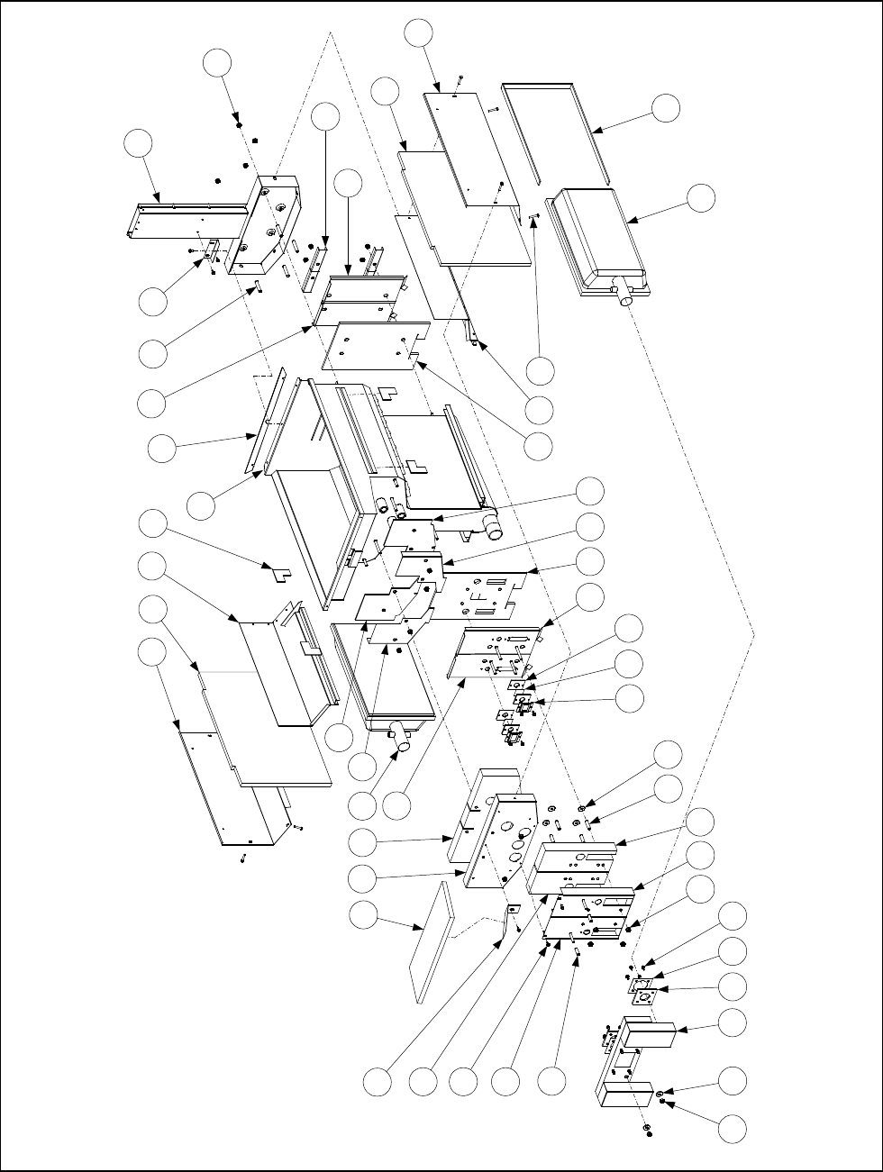
2-57
2.14.2 Full Vat Frypot Assembly, Component Parts
710 28 25 36 8
11 29 27
13 10
35 24 17
120 34 19
16 32 9
15
18
39
23
4
37
11
6
4012
31
21
30
23
39
19
3315
2
26
5
22
38
8
41
14
27
NOTE: All insulation and gaskets
can be ordered in a single kit, P/N
826-0929.
Kit 826-0931 contains the insulation
and gaskets required when replacing
burners (Items 16, 18, 20, and 25).
Full Vat Frypot Assembly (Typical)
3
43
See Page 2-58 for

2-58
ITEM PART # COMPONENT
Full Vat Frypot Assembly, Complete (see Page 2-58 for P/Ns)
1 823-3316 Retainer, Lower Front Insulation, Right (before 09/01 use 200-0934)
2 823-3315 Retainer, Lower Front Insulation, Left (before 09/01 use 200-0935)
3 200-0936 Back, Combustion Chamber, Left
4 200-0937 Back, Combustion Chamber, Right
5 200-2227 Retainer, Upper Front Insulation
6 106-1019SP Flue Assembly, Full Vat (before 09/01 use 806-5859SP)
7 826-1372 Nut, ¼-20 Hex Head Grip (Pkg of 10)
8 826-1371 Screw, #8 x ½-inch Hex Head Drill Point (Pkg of 25)
9 809-0362 Screw, # 8 x 1¼-inch Hex Head Drill Point
10 826-1383 Washer, ¾-inch OD x ¼-inch ID Steel (Pkg of 5)
11 809-0804 Nut, ¼-20 Washer-Face Lock
12 810-0406 Spacer, ¼-inch x 1½ -inch Long
13 826-1340 Spacer, ¼-inch x 13/16-inch Long (Pkg of 10)
14 810-0500 Spacer, ¼-inch x 15/16-inch Long
15 826-1072 Burner, Natural or Propane, Universal (use 826-1073 for Mfg gas)
16 812-0355 Insulation, Lower Rear
17 812-0356 Insulation, Sight Glass Gasket
18 816-0577 Insulation, Burner (½-inch x 36-inches)
19 812-0404 Insulation, Front Seal (for left and right)
20 812-0457 Insulation, Lower Front
21 812-0706 Insulation, Upper Burner Rail
22 812-0993 Insulation, Upper Oil Zone
23 812-1029 Insulation, Combustion Chamber Side
24 814-0048SP Sight Glass
25 816-0057 Gasket, Plenum Chamber
26 816-0560 Insulation, Upper Front
27 816-0561 Insulation, Combustion Chamber, Outer
28 823-0969 Plenum, Full Vat (for CE units, use 823-1048)
29 823-3304 Combustion Chamber Outer Front, Right (before 09/01 use 823-1169SP)
30 823-1777 Burner Rail, Left
31 Frypot, Full Vat (shown for assembly reference only)
32 823-3142 Burner Rail, Right
33 824-0863 Retainer, Left Front Seal Insulation
34 824-0864 Retainer, Right Front Seal Insulation
35 900-1031 Retainer, Sight Glass, ¾-inch
36 900-1049 Retainer, Plenum Chamber Gasket
37 900-1221 Retainer, Rear Insulation and Combustion Chamber Back
38 900-1515 Brace, Upper Oil Zone Insulation
39 900-4452 Retainer, Combustion Chamber Side Insulation
40 930-0818 Bracket, Flue to Frypot Connection
41 823-3305 Combustion Chamber Outer Front, Left (before 09/01 use 823-11691SP)
42 809-0500 Screw, #10 x ½-inch Hex Washer Head
43 900-4253 Strip, Fluecap Retainer
* 813-0156 Plug, ½-inch NPT BM (for blocking unneeded ports)
* 813-0336 Plug, ½-inch SS (for blocking unneeded ports)
* 910-2474 Pot-to-Pot Gap Clip
* 900-0857 Brace, Frypot to Cabinet
*Not illustrated.
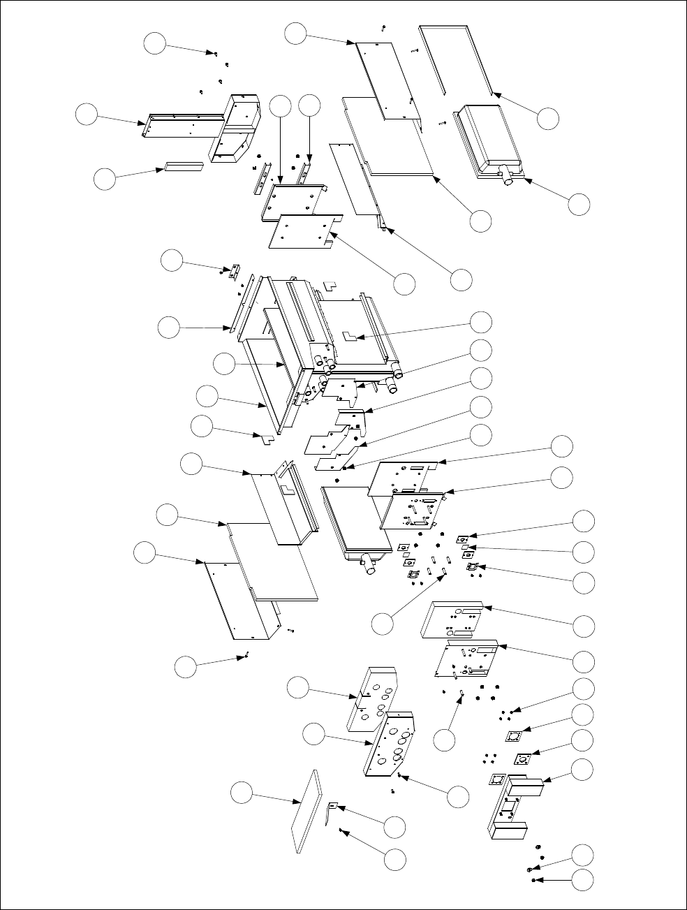
2-59
2.14.3 Dual Vat Frypot Assembly, Component Parts
NOTE: All insulation and gaskets
can be ordered in a single kit, P/N
826-0930.
Kit 826-0932 contains the insulation
and gaskets required when replacing
burners (Items 13, 15, 17, and 23).
Dual Vat Frypot Assembly (Typical)
4 7 23 36 531 24 35 22 14
30 17
932 33 16 19
13
28
12
15
38
21
34
2
8
1
18
39
29
19
27
21
38
6
25
3
20
537
8
11
26
10
41
40
See Page 2-58 for P/N’s

2-60
ITEM PART # COMPONENT
Dual Vat Frypot Assembly, Complete (see Page 2-58 for P/Ns)
1 106-1018SP Flue Assembly, Dual Vat (before 09/01 use 806-5860SP)
2 200-0941 Back, Combustion Chamber
3 200-2229 Retainer, Upper Front Insulation
4 826-1372 Nut, ¼-20 Hex Head Grip (Pkg of 10)
5 809-0360 Screw, #8 x ⅜-inch Slotted Hex Washer Head
6 809-0362 Screw, # 8 x 1¼-inch Hex Head Drill Point
7 826-1383 Washer, ¾-inch OD x ¼-inch ID Steel (Pkg of 5)
8 809-0500 Screw, #10 x ½-inch Hex Washer Head
9 809-0804 Nut, ¼-20 Washer-Face Lock
10 826-1340 Spacer, ¼-inch x 1 3/16-inch Long (Pkg. of 10)
11 810-0500 Spacer, ¼-inch x 15/16-inch Long
12 826-1072 Burner, Natural or Propane, Universal (use 826-1073 for Mfg gas)
13 812-0354 Insulation, Lower Rear
14 812-0356 Insulation, Sight Glass Gasket
15 816-0577 Insulation, Burner (½-inch x 36-inches)
16 812-0404 Insulation, Front Seal (for left and right)
17 812-0458 Insulation, Lower Front
18 812-0688 Insulation, Flue Collector
19 812-0706 Insulation, Upper Burner Rail
20 812-0993 Insulation, Upper Oil Zone
21 812-1029 Insulation, Combustion Chamber Side
22 814-0048SP Sight Glass
23 816-0057 Gasket, Plenum Chamber
24 816-0558 Insulation, Combustion Chamber, Outer
25 816-0559 Insulation, Upper Front
26 823-0970SP Plenum, Dual Vat (use 823-1049 for CE units)(823-2181 for H150-2’s)
27 823-2822 Burner Rail, Left
28 823-2823 Burner Rail, Right
29 Frypot, Dual Vat (shown for assembly reference only)
30 823-3302 Retainer, Lower Front Insulation (before 09/01 use 823-0983SP)
31 823-3303 Combustion Chamber Outer Front (before 09/01 use 823-0968SP)
32 824-0865 Retainer, Left Front Seal Insulation
33 824-0866 Retainer, Right Front Seal Insulation
34 900-0914 Retainer, Rear Insulation and Combustion Chamber Back
35 900-1031 Retainer, Sight Glass, ¾-inch
36 900-1049 Retainer, Plenum Chamber Gasket
37 900-1515 Brace, Upper Oil Zone Insulation
38 900-4452 Retainer, Combustion Chamber Side Insulation
39 930-0818 Bracket, Flue to Frypot Connection
40 900-4253 Strip, Fluecap Retainer
41 824-0541 Riser, DV Pot Divider W/A
* 910-2474 Pot-to-Pot Gap Clip
* 813-0156 Plug, ½-inch NPT BM (for blocking unneeded ports)
* 813-0336 Plug, ½-inch SS (for blocking unneeded ports)
* 900-0857 Brace, Frypot to Cabinet
*Not illustrated.
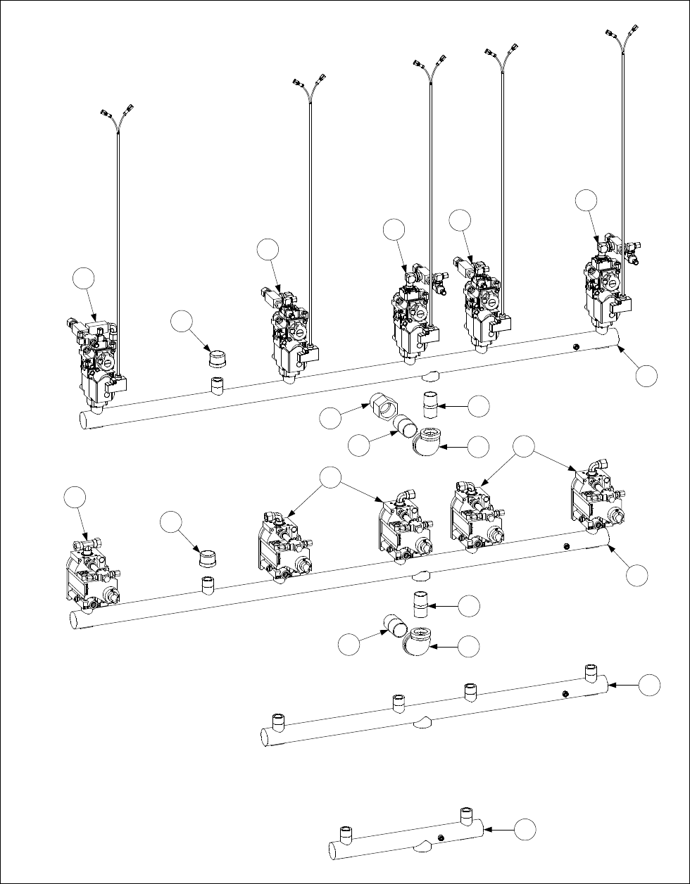
2-61
2.15 Gas Supply System Assemblies and Component Parts
2.15.1 FM/MJH50 Gas Manifold Assemblies
1
2
3
4
3
4
5
7
5
6
6
7
8
9
10
11
12
13
10
12
13
CE FM/MJH350-4R (Typical)
NON-CE FM/MJH350-4R (Typical)
See Page 2-63 for details of gas valve assemblies.

2-62
ITEM PART # COMPONENT
1 810-0959 FM/MJH150 Gas Manifold
2 810-0661 FM/MJH250 Gas Manifold
3 810-0660 FM/MJH350 Gas Manifold
4 813-0469 Cap, Pipe, ½-inch, BM
5 813-0111 Nipple, ¾-inch x 1¾-inch, BM
6 813-0305 Elbow, 1-inch x ¾-inch, BM
7 813-0138 Nipple, 1-inch x Close, BM
8 813-0505 Adapter, 1-inch NPT x 1-inch BSPT
9Gas Valve Assembly, Non-CE Full Vat
806-5304SP Natural Gas
806-5305SP Propane Gas
10 Gas Valve Assembly, Non-CE Dual Vat
806-5306SP Natural Gas
806-5307SP Propane Gas
11 Gas Valve Assembly, CE Full Vat
806-7467SP Natural (G20, G25) Gas
806-7466SP Propane (G30, G31) Gas
12 Gas Valve Assembly, CE Dual Vat (Left)
806-7465SP Natural (G20, G25) Gas
806-7464SP Propane (G30, G31) Gas
13 Gas Valve Assembly, CE Dual Vat (Right)
806-7463SP Natural (G20, G25) Gas
806-7462SP Propane (G30, G31) Gas
* 810-1306 Gas Valve, Manual ½”
* 810-1307 Gas Valve, Manual ¾”
NOTE: Batteries larger than FM/MJH350 use combinations of the above components (e.g., a FM/MJH450
uses one of Item 1 and one of Item 3 plus the appropriate gas valves and connection fittings for the specific
configuration).

2-63
2.15.2 Gas Valves, Gas Lines and Fittings
1
2
3
4
6
5
78910 11 12 13 14
22 23
24
25
15 16 17
18 19 20
21
26 28
27
27
29
30 30
27
27

2-64
ITEM PART # COMPONENT
1Gas Valve and Bushing, Non-CE
826-1122 Natural (G20, G25) Gas
826-1123 Propane (G30, G31) Gas
826-1576 Gas Valve and Harness CE
2 810-0691 Vent Tube (used with Item 1) (for CE units, use 810-1166)
3 810-1715 Gas Valve, Universal CE (G20/G25/G30/G31) adjustable 2” to 20”
4 810-1041 Accessory Kit (2 straight and 2 elbow flanges, screws, O-rings, LP gas spring)
5 806-9678SP Plug Assembly, CE Gas Valve (used with Item 3)
6 807-1229 Gas Valve, Manufactured Gas
7 810-1176 Tap, ⅛-inch NPT Pressure
8 813-0411 Plug, ⅛-inch NPT Allen-head Pipe
9 813-0304 Bushing, ½-inch to ¼-inch NPT Reducer
10 810-1006 Bushing, ¼-inch to ⅛-inch NPT Reducer
11 813-0004 Elbow, 90º x ⅛-inch NPT
12 813-0354 Elbow, 90º x ⅛-inch NPT x ⅛-inch Tube (Brass)
13 813-0302 Elbow, 90º x ⅜-inch Tube x ¼-inch Male NPT (Brass)
14 813-0502 Elbow, 90º Street x ¼-inch (Brass)
15 813-0340 Connector, ⅛-inch Tube to ⅛-inch Male NPT (Brass)
* 810-0502 Connector, ⅛-inch Tube to ⅛-inch Male NPT (Brass) (with Item 6 only)
16 810-1025 Connector, ⅜-inch Tube to ¼-inch Male NPT (Brass)
17 813-0507 Coupling, ¼-inch NPT (Brass)
18 813-0378 Cross Fitting, ½-inch Female NPT (Brass)
19 810-1026 Tee, ¼-inch NPT Street (Brass)
20 813-0495 Tee, ¼-inch Male NPT Branch (Brass)
21 813-0377 Tee, ⅛-inch Female NPT (Brass)
22 813-0016 Nipple, ⅛-inch NPT Close
23 813-0315 Nipple, ⅛-inch NPT x 1½-inch
24 813-0405 Nipple, ⅛-inch NPT x 2-inch
25 813-0471 Nipple, ¼-inch NPT x 1½-inch
26 900-3693 Gas Tube (Left), H50 FV Manufactured Gas (pre-formed)
27 810-0503 Compression Nut (Ferrule), ½-inch Manufactured Gas Tube
28 900-3692 Gas Tube (Right), H50 FV Manufactured Gas (pre-formed)
* 900-3691 Gas Tube (Left and Right), H50 DV Manufactured Gas (pre-formed)
29 Flexible Stainless Steel Gas Line (Flexline), ⅜-inch OD
810-1353 9-inch (22.9 cm) (826-1530 Kit includes 2 of Item 30)
810-1354 12-inch (30.5 cm)(826-1531 Kit includes 2 of Item 30)
810-1355 15-inch (38.1 cm) (826-1532 Kit includes 2 of Item 30)
30 810-0494 Compression Nut (Ferrule), ⅜-inch Flexible Gas Line
*Enrichment Tube, ⅛-inch OD
811-0752 5½-inch (14 cm)
811-0756 8½-inch (21.6 cm)
811-0800 12½-inch (31.8 cm)
812-0742 18-inch (45.7 cm)
900-7450 20-inch (51 cm)
811-0759 Variable Length (sold by the foot)
* 810-1166 Vent Tube CE (used with Item 3)
* 813-0340 Fitting, Enrichment Tube for Gas Valve End
* 810-0502 Fitting, Enrichment Tube for Ignitor Connection
* Not illustrated.

2-65
2.16 Probe, Probe Guard and Thermostat
1
2
3
ITEM PART # COMPONENT
1 826-1177 High Limit Thermostat (425°F/218°C)
2 806-4206 Temperature Probe Assembly
3 210-0681 Probe Guard (replaced 810-0625)
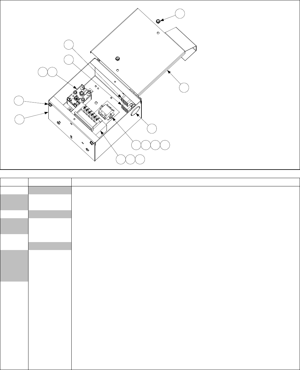
2-66
2.18 Relays, Transformers, Wiring Assemblies and Related Parts
2.18.1 Filter Box Components
14
1
2
10
13
9
9
4 5 7
93
6 8 11 12 NOTE: The transformer (Item 4)
may differ in appearance from the
illustration depending upon the
voltage of the filter system.
NOTE: See illustrations on Page 2-69
to determine the correct plug assembly
and harness required for your specific
configuration.
Complete Assemblies:
806-8581SP 100V w/4-Terminal Relay
806-8358SP 120V w/4-Terminal Relay
806-7496SP 120V w/5-Terminal Relay
806-8582SP 208/250 w/4-Terminal Relay
For FM see 806-6209
ITEM PART # COMPONENT
1Plug Assembly, Top Position
806-6725SP 4-Wires w/o keying plug (see illustration on Page 2-69)
806-8021SP 6-Wires w/keying plug in pin 5 (see illustration on Page 2-69)
2Plug Assembly, Bottom Position
806-6719SP 5-Wires w/o keying plug in pin 6 (see illustration on Page 2-69)
806-7494SP 5-Wires w/keying plug in pin 6 (see illustration on Page 2-69)
3 807-2434 Relay, 5-Terminal Pump Motor (for 4-Terminal, use 807-0012)
4Transformer
807-2176 100-120V Primary 12/24V Dual-Tap Secondary 50/60 Hz 50VA
807-0855 120V Primary 12V Secondary 50/60Hz, 20VA
807-0800 120V Primary 24V Secondary 50/60 Hz 50VA
807-1999 202-240V Primary 24V Secondary 50/60 Hz 50VA
5 809-0096 Screw, 6-32 x ⅝-inch Slot Head
6 826-1366 Nut, 4-40 Keps Hex (Pkg. of 25)
7 809-0250 Nut, 6-32 Keps Hex
8 826-1359 Screw, 4-40 x ¾-inch Slotted Pan Head (Pkg. of 25)
9 809-0360 Screw, #8 x ⅜-inch Slotted Washer Hex Head
10 810-0044 Plug, ⅝-inch
11 810-1164 Terminal Block
12 816-0217 Paper, Insulating
13 900-5250 Box, FP III Filter
14 900-5530 Cover, FP III Filter Box
* 810-1062 Harness, Filter Box
* Not illustrated
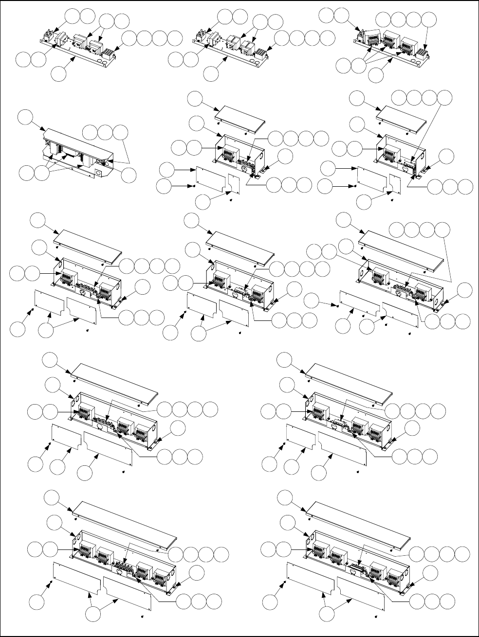
2-67
2.18.2 Transformer Box Components
40
32
229
39
22 212 16
25
18 21 27 29
123
236
723
3 4 18 21
43 FPH150 (100V)
123 523
3 4 18 21
236
43 FPH150 (120V)
231
43
211843
239
FPH150 (208-240V)
44
2443
23926
FPH150 (208-240V)
"Baby FootPrint"
41
31
2210
25
36
22
42 MJ/FMH150 (100-120V)
41
31
229
12 162
42
22
36
25
30282118
MJ/FMH150 (208-240V)
35
34
2210
36
22
25
212 16
813 14 17
35
34
229
36
22
212 16 212 16
25
813 14 17 18 21 28 30
MJ/FM/FPH250 (100-120V) MJ/FM/FPH250 (208-240V)
47
46
2210
22
48 45 212 16
25
1714138
MJ/FM/FPH250 RF (100-120V)
22 36 38
229
37
33
212 16
25
MJ/FM/FPH350 (208-240V)
18 21 28 30
MJ/FM/FPH450 (100-120V) MJ/FM/FPH450 (208-240V)
40
32
2210
22
39
11 13 15 20
25
212 16
37
33
2210
22 36 38
212 16
25
813 14 17
MJ/FM/FPH350 (100-120V)
Note: H450 went to
2-Double Boxes
April 2001

2-68
ITEM PART # COMPONENT
1 807-0012 Relay, 18 Amp ⅓-HP 24V Coil
2 807-0070 Terminal Lug, Brundy KPA4C
3 807-0255 Terminal Jumper
4 807-0273 Terminal Block, 16-Pin
5 807-0800 Transformer, 120V Primary 24V Secondary 50/60 Hz 50VA
6 807-0855 Transformer, 120V Primary 12V Secondary 50/60 Hz 20VA
7 807-1238 Transformer, 100V Primary 24V Secondary 50/60 Hz 50VA
8 807-1973 Connector, 4-Post Terminal
9 807-1999 Transformer, 202-240V Primary 24V/12V Secondary 50/60 Hz 50VA Dual Tap
* 807-0979 Transformer, 208/240V Primary 12V Secondary 50/60Hz 20VA
* 806-4000 Transformer Assy. 220/240V Primary 12V Secondary 50/60Hz 40VA
(German & Dutch) requires fuse 807-1597
* 807-2180 Transformer, 208-240V Primary 24V Secondary 50/60Hz 50VA
* 806-4001SP Transformer, 220/240V Primary 24V Secondary 50/60Hz 75 VA (German & Dutch)
Requires fuse 807-1597
10 807-2176 Transformer, 100-120V Primary 12/24V Dual-Tap Secondary 50/60 Hz 50VA
11 807-2608 Terminal Block, 50A 2-Stud/Pole Post
12 809-0050 Nut, 2-32 Hex
13 809-0052 Nut, 10-24 Hex
14 826-1362 Nut, ¼-20 Hex (Pkg. of 10)
15 826-1365 Screw, 6-32 x ⅜-inch Slotted Truss Head (Pkg. of 25)
16 826-1363 Screw, 2-32 x ½-inch Slotted Truss Head (Pkg. of 25)
17 826-1389 Screw, ¼-20 x ¾-inch Hex Head (Pkg. of 10)
18 826-1366 Nut, 4-40 Keps Hex (Pkg. of 25)
19 809-0247 Nut, 2-32 Keps Hex
20 809-0250 Nut, 6-32 Keps Hex
21 826-1359 Screw, 4-40 x ¾-inch Slotted Pan Head (Pkg. of 25)
22 809-0360 Screw, #8 x ⅜-inch Slotted Hex Washer Head
23 826-1371 Screw, #8 x ½-inch Hex Head (Pkg. of 25)
24 809-0362 Screw, #8 x 1- Hex Washer Head
25 826-1374 Screw, #10 x ½-inch Hex Washer Head (Pkg. of 25)
26 810-0045 Bushing, .875 Diameter
27 810-1162 Terminal Block, 4 Place
28 810-1163 Terminal Block, 3 Place
29 816-0218 Paper, 4 Place Terminal Block Insulating
30 816-0219 Paper, 3 Place Terminal Block Insulating
31 900-2697 Box, Transformer H150/H152
32 900-2698 Box, Transformer H450/H452
33 900-2699 Box, Transformer H350/H352
34 900-2700 Box, Transformer H250/H252
35 900-2702 Cover, H250/252 Transformer Box Top
36 900-2703 Cover, H50/H52 Transformer Box Front (H150 L, H250 L & R, H350 L)
37 900-2704 Cover, H350/H352 Transformer Box Left Top
38 900-2705 Cover, H350/H352 Transformer Box Right Front
39 900-2706 Cover, H450/H452 Transformer Box Left and Right Front
40 900-2707 Cover, H450/H452 Transformer Box Top
41 900-2708 Cover, H150/H152 Transformer Box Top
42 900-2709 Cover, H150/H152 Transformer Box Right Front
43 900-4555 Bracket, Transformer Mount
44 900-5560 Shield, Component
45 900-5923 Cover, H250/H252 Transformer Box Right Front
46 900-5924 Box, H250/H252 Transformer
47 900-5927 Cover, H250/H252 Transformer Box Top
48 900-5928 Cover, H250/H252 Transformer Box Left Front
* 806-7999SP FPH150 Basket Lift Wiring Assembly
* Not illustrated.
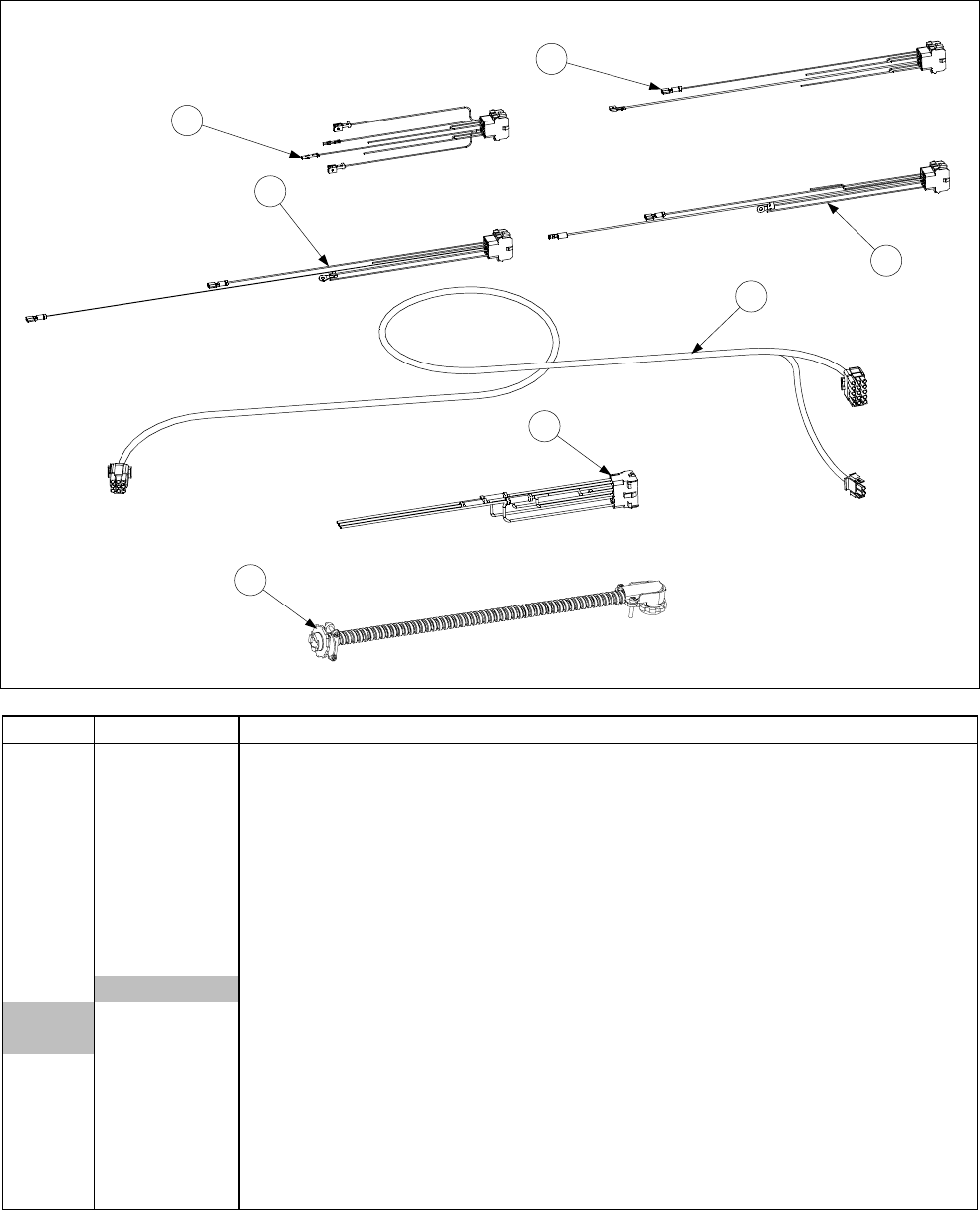
2-69
2.19 Wiring Harnesses, Wiring Assemblies and Plug Assemblies
Filter Box Wiring
1
2
3
4
5
6
7
ITEM PART # COMPONENT
1 806-8021SP 120V U.S. and 100/120V Non-CE Export Upper 9-Pin Plug Assembly
2 806-7494SP 120V U.S. Lower 9-Pin Plug Assembly (Main)
3 806-6725SP 230V CE Upper 9-Pin Plug Assembly
4 806-6719SP 100/120V Non-CE Export and 230V CE Lower 9-Pin Plug Assembly
5 810-1062 Cable, Filter Box Lower 9-Pin Plug to 807-2000/2001 C2 Connector (FP) w/ BL
* 807-2016 Cable, Filter Box Lower 9-Pin Plug to 807-2000/2001 C2 Connector (FM) Main
Wiring Harness
* 807-2000 Cable, 810-1062 C2 Connector to Component Box (units w/Basket Lift)
6 807-2001 Cable, 810-1062 C2 Connector to Component Box (units w/o Basket Lift)
7Pump Motor to Filter Box Wiring Assembly
806-6728SP FootPrint
806-4347 Filter Magic
* 807-3695 H50 Basket Lift Cable
* 807-0160 12-pin Connector Male FPH150
* WIR0129SP FPH150 Rear Ext. Box
* WIR0233SP 100-250V CE and Non-CE Export Filter Box Internal Wiring Bundle
* WIR0234SP 120V U.S. Filter Box Internal Wiring Bundle
* WIR0355SP FPH150 Rear Ext. Box (Panda Express)
* Not illustrated.
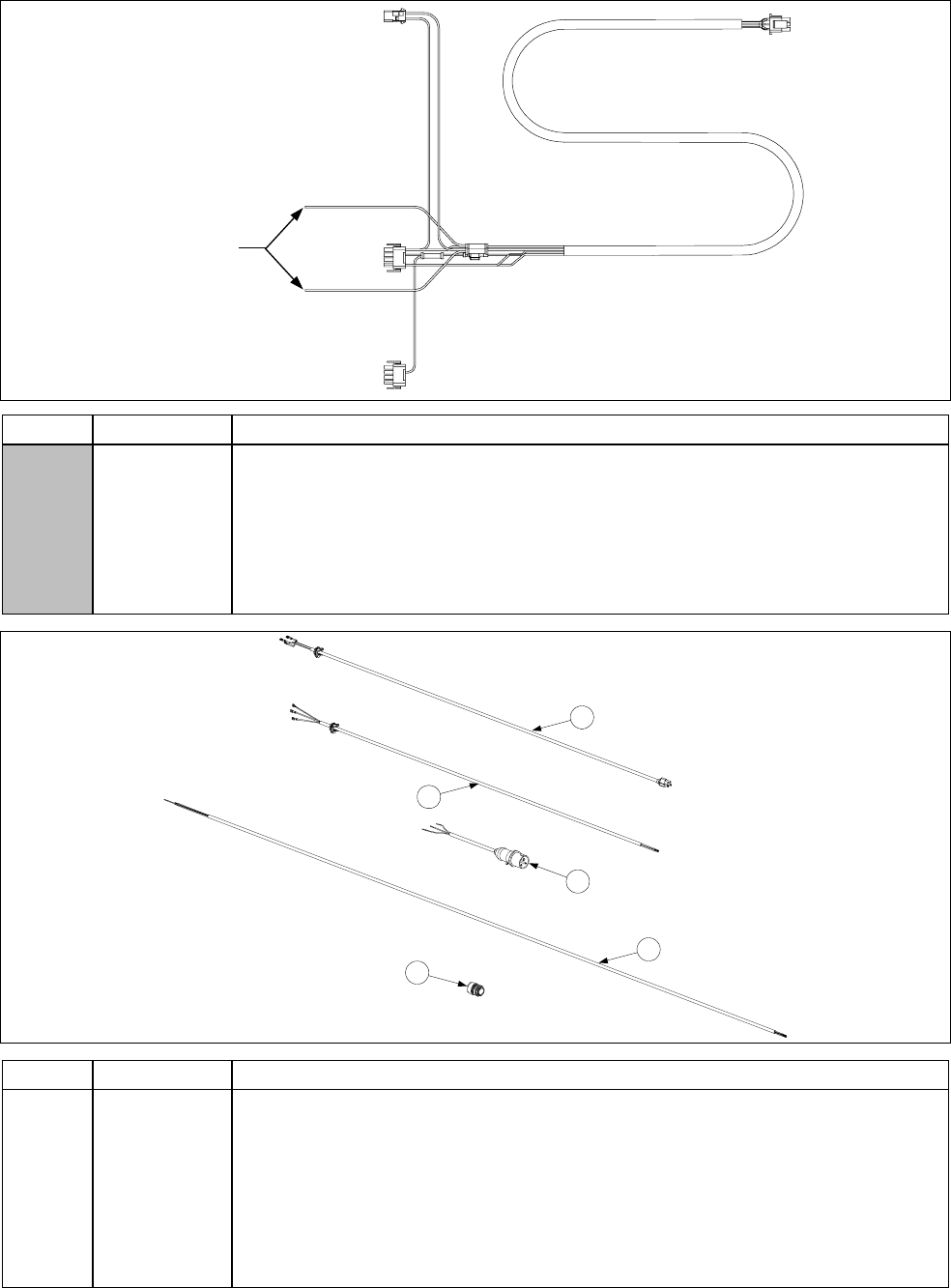
2-70
Main Wiring Harnesses
U.S. and Non-CE harness (shown)
has two unterminated wires.
Unterminated wires.
CE harness has two unterminated
wires plus two additional wires with
push-on terminals.
ITEM PART # COMPONENT
807-1978 U.S. and Non-CE Export (before 05/95, use 806-2076SP)
806-2077SP U.S. and Non-CE Export (DV before 05/95)
807-2168 CE Main Wiring Harness
806-2071 Interface Harness- Computer to Interface Board
807-2275 Interface Harness- Computer to Interface Board (MFG Gas Only)
807-2657 Ferrite Collar Bead
4
5
Power Cords
1
3
2
ITEM PART # COMPONENT
1 806-5332SP Power Cord, 120V w/Grounding Plug (w/Push-On Terminals and Clamp)
* 806-7742 Power Cord, 120V w/Grounding Plug (w/Ring Terminals, no Clamp)
* 807-0154 Power Cord, 120V w/Grounding Plug (w/o Terminals or Clamp)
2 806-6229SP Power Cord, 240V w/o Plug
3 807-1696 Power Cord, CE
4 807-1685 Power Cable, 110-inch, 3-wire, 16-gauge, 450V, 18A
5 807-1560 Strain Relief

2-71
1
5
9
2
6
10
3
7
11
4
8
Transformer Box Plug Assemblies
12
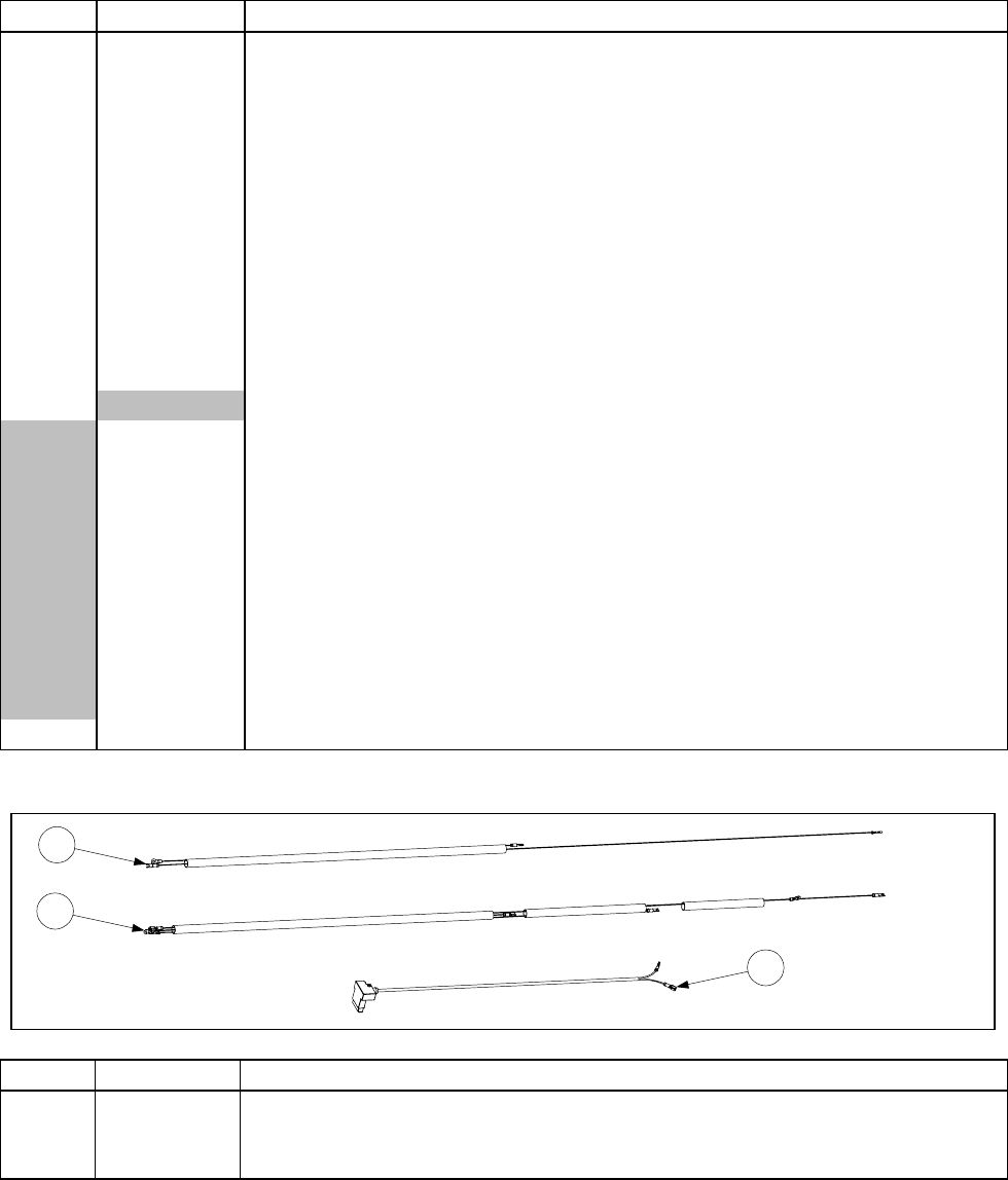
2-72
ITEM PART # COMPONENT
1 806-6164SP FMH150, MJ/FM/FPH250-Right, MJ/FM/FPH350/450-Left Front
2 806-6165SP MJ/FM/FPH250-Left, MJ/FM/FPH350/450-Left Rear
3 806-6166SP MJ/FM/FPH350-Right, MJ/FM/FPH450-Right Rear
4 806-6167SP MJ/FM/FPH450-Right Front
5 806-6637 FMH150 CE, MJ/FM/FPH250 CE-Left
6 806-6638 MJ/FM/FPH350 CE-Left Front, MJ/FM/FPH450 CE-Left Rear
7 806-6639 MJ/FM/FPH350 CE-Left Rear, MJ/FM/FPH450 CE-Left Front
8 806-6640 MJ/FM/FPH450 CE-Right Front
9 806-6641 MJ/FM/FPH350 CE-Right, MJ/FM/FPH450 CE-Right Rear
10 806-6642 MJ/FM/FPH250 CE-Right
11 806-8712SP MJ/FM/FPH250-Left
12 806-8713 MJ/FM/FPH250-Right
*Transformer Box Wire Bundle
WIR0110SP MJ/FMH150, MJ/FM/FPH250
WIR0111SP MJ/FM/FPH350
WIR0112 MJ/FM/FPH450
WIR0129SP FPH150
WIR0149 MJ/FM/FPH250 CE
WIR0150 MJ/FM/FPH350 CE
WIR0151 MJ/FM/FPH450 CE
WIR0152 MJ/FMH150 CE
WIR0355SP FPH150 (Panda Express Variant)
WIR0365 FPH150 CE (Baby FootPrint Variant)
* 807-0156 9-Pin Connector Female
* Not illustrated.
Gas Valve Wiring
1
2
3
ITEM PART # COMPONENT
1 806-3941SP Harness, Full Vat Gas Valve
2 806-3940SP Harness, Dual Vat Gas Valve
3 806-9678SP Plug Assembly, CE Gas Valve
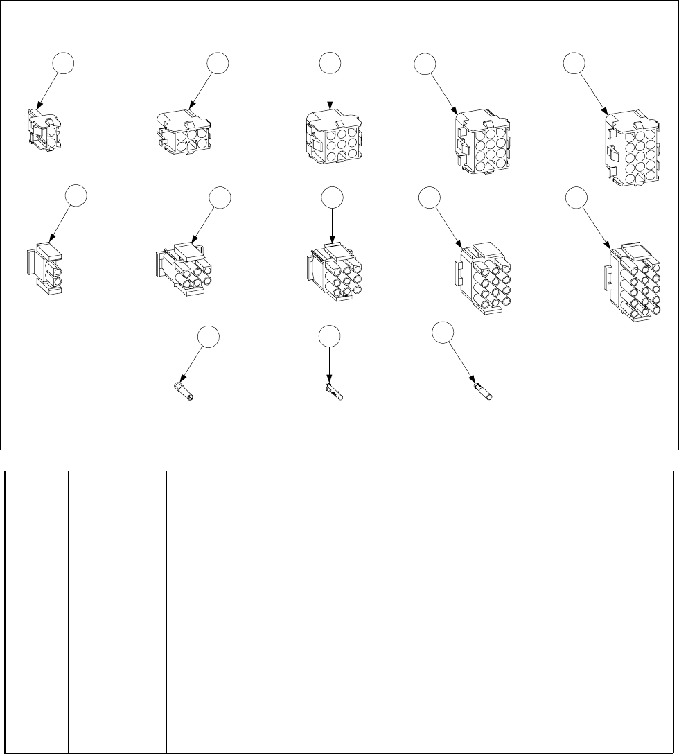
2-73
2.20 Wiring Connectors and Pin Terminals
1 2 45
3
67 9 10
8
11 13
12
ITEM PART # COMPONENT
1 807-1068 2-Pin Female
2 807-0158 6-Pin Female
3 807-0156 9-Pin Female
5 807-0159 12-Pin Female
5 807-0875 15-Pin Female
6 807-1067 2-Pin Male
7 807-0157 6-Pin Male
8 807-0155 9-Pin Male
9 807-0160 12-Pin Male
10 807-0804 15-Pin Male
11 826-1341 Terminal, Female Split Pin (Pkg of 25)
12 826-1342 Terminal, Male Split Pin (Pkg of 25)
13 807-2518 Plug, Mate-N-Lock (Dummy Pin)
THIS PAGE INTENTIONALLY LEFT BLANK

Frymaster, L.L.C., 8700 Line Avenue, PO Box 51000, Shreveport, Louisiana 71135-1000
Shipping Address: 8700 Line Avenue, Shreveport, Louisiana 71106
TEL 1-318-865-1711 FAX (Parts) 1-318-219-7140 FAX (Tech Support) 1-318-219-7135
PRINTED IN THE UNITED STATES SERVICE HOTLINE
1-800-551-8633 819-0001
JUNE 2005
