Fsl Muse Quickstart User Manual
Muse Quickstart Muse_Quickstart Muse_Quickstart pdfs production website
Muse Quickstart Muse_Quickstart Muse_Quickstart pdfs local website fsl-public
2017-03-23
User Manual: Fsl Muse Quickstart Muse_Quickstart pdfs staging website
Open the PDF directly: View PDF ![]() .
.
Page Count: 2
LASER TUBES:
45W Laser Tube.
FOCUS LENSES:
1.5” Lens, 2” Lens, 2.5” Lens, 5” Lens.
ROTARY/RISER ATTACHMENTS:
Friction Rotary, Muse Riser.
WATER ASSIST:
Passive Water Chiller, Active Water Chiller.
AIR ASSIST:
Air Compressor, Exhaust Fan, Large Exhaust Fan.
EXTRACTORS & FILTERS:
Large, Medium & Small Fume Extractors.
Large, Medium & Small Filter Replacements.
SUPPORT MANUALS
SALES SOFTWARE
Full Spectrum Laser provides the best customer support in the industry. Contact us if you have any questions or issues with your Muse Laser Cutter.
We can also offer convenient purchasing of accessory upgrades and replacement of consumable items. Refer to this sheet for all your customer
support and reordering needs.
PLEASE CONTACT OUR TEAM
ORDER ACCESSORIES & UPGRADES
M-F 8am to 5pm (PST)
support@fslaser.com
702.802.3103
For a PDF of the user manual
fslaser.com/support
M-F 8am to 5pm (PST)
sales@fslaser.com
702.802.3101
Access RetinaEngrave 2.0 by typing IP address
displayed on the touch screen into your browser
QUICK START GUIDE
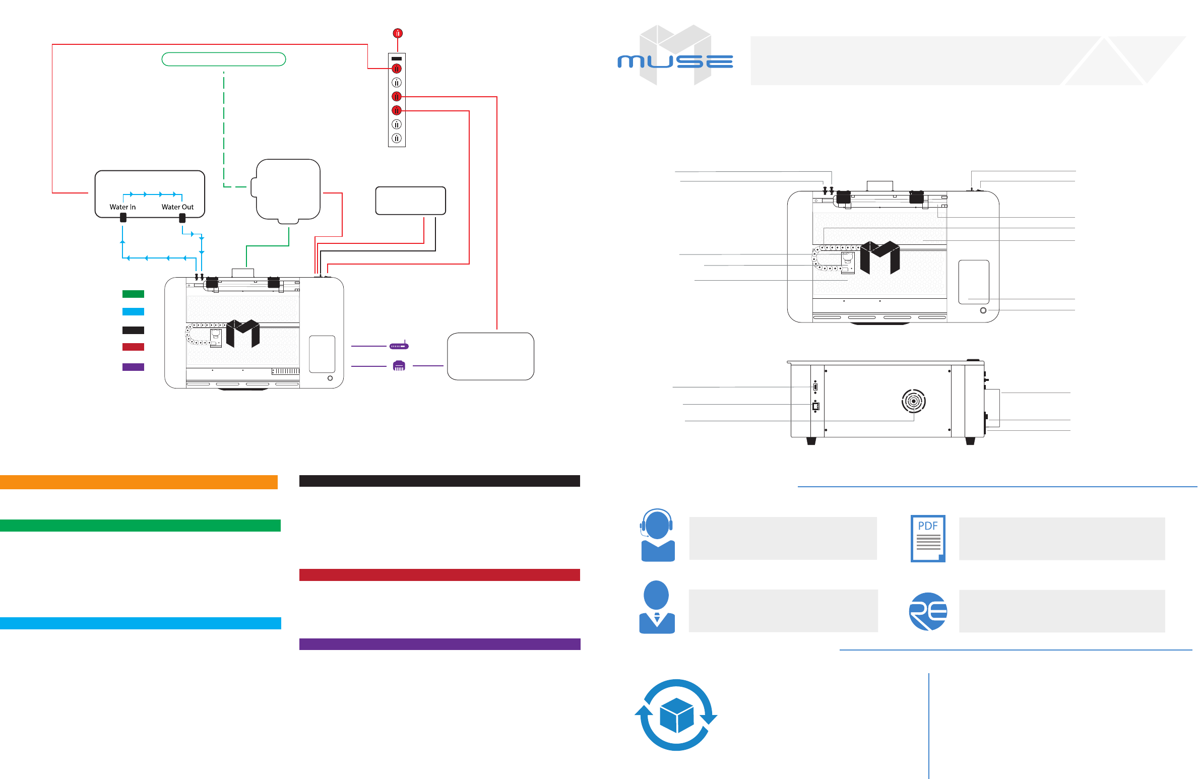
B. CONNECT THE EXHAUST SYSTEM
1. Position ducting on Muse exhaust port and secure with 4” ducting clamp.
2. Attach other end of ducting to ange side of exhaust fan, then the second
ducting to the exit port of the exhaust fan.
3. Ventilate the ducting outside through a window or exhaust port.
- If using a fume extractor, you can attach the ducting from Muse directly to
the fume extractor, and bypass the exhaust fan completely.
D. ASSEMBLE THE AIR COMPRESSOR
1. Remove the air compressor from its packaging. Gently attach on the push
tting to the air compressor.
2. Push one end of the black air inlet hose over the air compressor push
tting until it is snug.
3. Insert the other end of the black air inlet hose into the “air inlet” nozzle in
the back of laser cutter via the barbed air connect tting.
E. CONNECT POWER
1. The power cord plugs into a “C14” power receptacle located on the right
side of the machine.
2. Follow the diagram and connect all power connections to a central power
bank and then plug the power strip into an appropriate wall outlet.
F. CONNECT THE ETHERNET CABLE
1. Locate and remove the included Ethernet cable from its packaging.
2. Plug in the Ethernet cable into the Ethernet slot on your Muse.
3. Plug the other end of the Ethernet cable into your computer’s Ethernet slot.
4. Connect Via Router (Recommended): Router connectivity is more reliable than
directly connecting via Ethernet and should be the primary way of connecting.
You can also connect via Wi-Fi.
C. ASSEMBLE THE WATER SYSTEM
- If using a water chiller, attach the inlet and outlet water tubing as shown in
the diagram above. Add distilled water as instructed.
1. If using a water pump/bucket system, remove the water pump from its
packaging and gently screw on the plastic tting.
2. Push one end of one of the two (2) silicone water tubes onto the water
pump tting. Now attach the other end of that tubing to the “water inlet”
located at the back of machine. Completely submerge the assembled water
pump in the bucket of distilled water.
3. Fill a clean 5 gallon bucket (not included) with 3 - 4 gallons of distilled
water. It is best to use a bucket with a lid and cut two holes to secure the
water tubing. This will prevent debris from contaminating the water.
4. Push one end of the other silicone water tubing onto the “water outlet”.
Place the other end of the water tubing into bucket of distilled water.
Your Muse will require some minor assembly of the accessory systems, such as the water system. This process should take less than an hour to complete.
Your Muse User Manual has complete assembly instructions.
Quick Start Muse Assembly
Water In
Water Out
Air Tubing
Power Cords
Water Tubing
Ducting
Software Connection
Window/ Exhaust Port
Cooling System
Computer
Options
Power Strip
Wall Outlet 110 V
Air
Compressor
Exhaust
System
Top View
Side View
Water Inlet
Water Outlet Power On/O
Air Inlet
45 Watt Laser Tube
X-Gantry
Focus Head
Wide Angle Camera
Honeycomb Tray
Touchscreen
20”x12” Engraving Area
Pause/Stop Button
USB Port Exhaust Flange
Ethernet Port
Cooling Vents Air Compressor Power Outlet
Exhaust Fan Power Outlet
A. LOCATE AND CUT YELLOW ZIP TIES
- Cut and remove the yellow zip ties that secures the laser head to the back
of the machine.
NEVER leave your machine unattended while it is operating.
ALWAYS use the air assist and the exhaust system when operating the
machine. Failure to do so can increase the re risk and cause damage
to the machine’s parts, particularly the focus lens.
BE AWARE that removal of any portion of the cabinet will expose a
Class 4 laser system and greatly increase the risk of injury and/or re.
KEEP the area around the machine clean and free of clutter,
combustible materials, explosives, or volatile solvents such as acetone,
alcohol or gasoline.
KEEP YOUR LASER SYSTEM CLEAN – A build-up of cutting and
engraving residue and debris is dangerous and can create a re hazard.
Keep your laser system clean and free of debris. Regularly remove the
cutting grid to clean any small pieces that have gotten stuck or
fallen through.
ALWAYS keep a properly maintained and inspected 5lbs. or larger
re extinguisher on hand. Full Spectrum Laser recommends a
C02 re extinguisher.
NEVER engrave or cut any material containing PVC or vinyl as corrosive
gases will occur that can cause harm to the operator, as well as damage
the machine and void the warranty. Never engrave or cut any
unknown material.
DO NOT look into the beam of the Alignment Laser (visible red diode laser).
DO NOT run laser with lid open. Always be sure the lid is closed and never
tamper with lid safety mechanism.
NEVER operate the machine without a properly operating ventilation
system. Most materials produce an irritating smoke when engraved. Some
materials, including but not limited to paint, varnish, composition board
and plastics, produce compounds that can be harmful if concentrated.
POWER ON/OFF is controlled by the switch at the back of the machine.
To power the machine on, press the (-) side down. To turn power off, press
the “o” side down. You can use this switch should you ever need to cut
power immediately.
DO NOT make or break any electrical connections to the system while the
unit is turned on.
DO NOT access or tamper with any electronics unless specically directed
to by support, as electronics have high voltage components.
There is no download required for RetinaEngrave 2.0. With a local
connection (achievable with the included Ethernet cable) your Muse will link
with the software’s IP address.
ATTENTION! The laser must be powered on when operating the
software or when connecting the laser via the Ethernet cable.
1. Turn On Muse: Turning on your Muse will automatically boot up your
Muse touch screen interface. Allow a minute or so for the machine and touch
screen to boot up.
2. Go To Settings: On the touch screen interface, push the gear icon to go
to Settings.
3. Choose Network: Push “Network” at the top center of the screen.
4. Type IP Into Browser: Type IP Into Browser: On the Main Touch Screen
you will see a “Wired IP” number at the bottom of the display. Using your
computer, type this IP number into your favorite browser (Google Chrome,
Explorer, etc). This will link you to the RetinaEngrave 2.0 interface. You now
have full access to the software. You can also access a “Wireless” IP by
clicking the settings icon.
1. Safety First: Ensure workspace is free of re, electrical and other safety
hazards. Be aware of all safety issues when cutting materials with a laser.
Always have a re extinguisher on hand.
2. Power on the laser and all of its components.
3. Ensure that:
- The laser is powered and the boot up cycle begins on the screen.
- The cooling system is connected properly and water is owing through the tube.
- The air compressor is powered and exhausting air to the laser head.
- The exhaust system is on and vented into a safe location.
4. Connect to RetinaEngrave 2.0 software using your machine’s touch screen
to copy the software IP address into your favorite browser. The Wired IP
address is displayed at the bottom of your touch screen.
5. Import your design and adjust power and speed settings. Double check
settings including the number of passes and cut order.
6 Insert material into the laser bed. Use the focus tool to adjust to the top of the
material. Focusing should be done each time a new material is introduced.
7. Use the “Perimeter” function to ensure that the le will t within the cutting
area. Adjust accordingly.
8. Run the job le. Do not leave a job running unattended.
To ensure the maximum output for your laser cutter, be aware of periodic
maintenance requirements. Before every job, always be sure your water, air and
power are operational as well as checking that the machine and workspace are
clutter-free. For long term care, relative to use, follow these guidelines:
WEEKLY
Use optical grade lens wipes to clean both sides of the beam combiner, all
mirror surfaces, the focus lens, and the tube aperture. Optic surfaces may
need to be cleaned more often if cutting materials produce excessive residue.
Clean fallen debris from the catch tray of the machine. Less excess material
will reduce re risk and provide for better exhausting. Always keep rails,
motors and moving parts free from excess material as it can obscure
movement and cause damage.
MONTHLY
Check rail lubrication. When the laser arrives, you should be able to visibly
see the lubricant on the x and y rails. These rails will not need to be re-
lubricated often, but check monthly to be sure that the rails are properly
lubricated and aren’t grinding or catching.
Check your fume extractor lters. Depending on your output and the
materials being cut, your fume extractor lters may need to be replaced
as often as every month.
QUARTERLY
Change water in cooling system. This will keep your tube safe from
unwanted debris, mold or evaporation. A chiller system is enclosed and
will stay relatively clean and undisturbed, but it is good practice to check and
change the water as needed.
SAFETY GUIDELINES
GENERAL SAFETY
ACCESS RETINAENGRAVE 2.0 MAINTENANCETOUCH SCREEN INTERFACE
MIRROR ALIGNMENT TEST
WORKFLOW CHECKLIST
FIRE SAFETY
LASER SAFETY
ELECTRICAL SAFETY
The following safety guidelines are meant to highlight the most common
safety violations. Use of controls or procedures other than those specied
herein may result in hazardous radiation exposure, res or electric shock.
Please refer to your user manual for a complete listing of safety protocol.
The CO2 and Alignment Laser beams were matched to follow the same path
through the mirrors and re down the center of the focusing head. Before
starting your rst job, check to see that the alignment has not been altered
by the shipping process.
This checklist presents a “best practice” for each time you run a project.
Refer to this checklist often until you are comfortable operating your Muse.
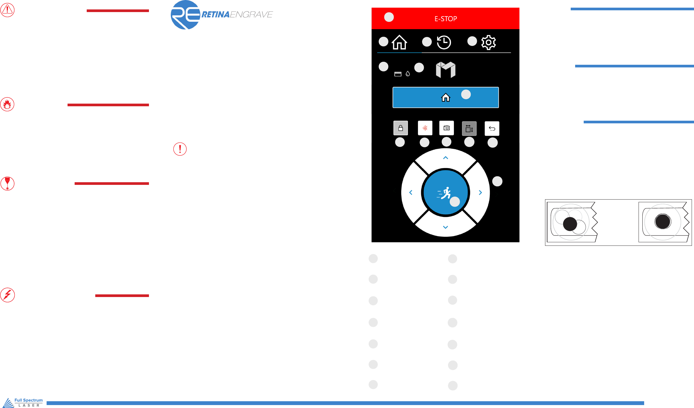
Muse’s touch panel allows you to control the basic functions of your laser
without needing to connect to a computer. This is very convenient during
alignment and testing procedures. To actually run jobs, you will need to
access the RetinaEngrave 2.0 software.
MAIN MENU
Returns to Main Screen from
any sub-screen
JOB HISTORY
Accesses Job History
sub-screens
SETTINGS
Accesses the Settings
sub-screens
RETURN TO POSITION
Return gantry to a custom
assigned position
WATER INDICATOR
Indicates water system
is running properly
LID OPEN / CLOSE
Indicates lid is opened
or closed
DIRECTIONAL JOG
Jog gantry left, right, up or down
LOCKED/UNLOCKED
Lock or unlock the gantry
for auto or manual maneuvering
HOME LASER
Instantly homes the laser
TEST FIRE
Test re the laser. Used for
mirror alignments and testing
JOG PERIMETER
Laser automatically JOGs the
extent of the current project
E-STOP
Instantly stop any action
A
B
C
D
E
F
G
I
H
J
K
L
M
N
O
P
Q
R
S
T
U
A
B
C
D
E
F
G
I
H
J
K
L
M
N
O
P
Q
R
S
T
U
A
B
C
D
E
F
G
I
H
J
K
L
M
N
O
P
Q
R
S
T
U
A
B
C
D
E
F
G
I
H
J
K
L
M
N
O
P
Q
R
S
T
U
A
B
C
D
E
F
G
I
H
J
K
L
M
N
O
P
Q
R
S
T
U
A
B
C
D
E
F
G
I
H
J
K
L
M
N
O
P
Q
R
S
T
U
A
B
C
D
E
F
G
I
H
J
K
L
M
N
O
P
Q
R
S
T
U
A
B
C
D
E
F
G
I
H
J
K
L
M
N
O
P
Q
R
S
T
U
A
B
C
D
E
F
G
I
H
J
K
L
M
N
O
P
Q
R
S
T
U
A
B
C
D
E
F
G
I
H
J
K
L
M
N
O
P
Q
R
S
T
U
A
B
C
D
E
F
G
I
H
J
K
L
M
N
O
P
Q
R
S
T
U
A
B
C
D
E
F
G
I
H
J
K
L
M
N
O
P
Q
R
S
T
U
FSLaser.com
1. Open the Safety Lid: You will need to access the interior of the machine.
2. Place Thermal Paper: Take a small piece of thermal paper (approx. 15
mm should be plenty) and place it over the focal lens under Mirror#3.
3. Position Laser Head: Move the laser head into the upper left corner
of the workspace.
4. Close Safety Lid: Safety measures should make it impossible to re the
laser with the safety lid open. Regardless, never attempt to re the laser with
safety lid open.
5. Test Fire the Laser: Press the Fire Laser Icon Button on the touch screen.
6. Repeat Test Fire in Other Three Corners: Without removing the thermal
tape, repeat ring the laser once in each of the other corners of the machine
(Upper Right, Lower Right, and Lower Left).
7. Check Results: With the forth corner test re complete, open the lid and
remove the thermal tape. The four burn marks should overlap each other
perfectly (see illustration). If they do not overlap perfectly, you will need to
align the mirrors.
Not Aligned Aligned
CAMERA
Instructs camera to
image workbed
A
B
C
D
E
F
G
I
H
J
K
L
M
N
O
P
Q
R
S
T
U
A
B
C
D
E
F
G
I
H
J
K
L
M
N
O
P
Q
R
S
T
U
JOG SPEED
Switch from slow jog to fast jog
A
B
C
D
E
F
G
I
H
J
K
L
M
N
O
P
Q
R
S
T
U
A
B
C
D
E
F
G
I
H
J
K
L
M
N
O
P
Q
R
S
T
U
A
B
C
D
E
F
G
I
H
J
K
L
M
N
O
P
Q
R
S
T
U
A
B
C
D
E
F
G
I
H
J
K
L
M
N
O
P
Q
R
S
T
U
A
B
C
D
E
F
G
I
H
J
K
L
M
N
O
P
Q
R
S
T
U
A
B
C
D
E
F
G
I
H
J
K
L
M
N
O
P
Q
R
S
T
U
A
B
C
D
E
F
G
I
H
J
K
L
M
N
O
P
Q
R
S
T
U
A
B
C
D
E
F
G
I
H
J
K
L
M
N
O
P
Q
R
S
T
U
A
B
C
D
E
F
G
I
H
J
K
L
M
N
O
P
Q
R
S
T
U
A
B
C
D
E
F
G
I
H
J
K
L
M
N
O
P
Q
R
S
T
U
A
B
C
D
E
F
G
I
H
J
K
L
M
N
O
P
Q
R
S
T
U
A
B
C
D
E
F
G
I
H
J
K
L
M
N
O
P
Q
R
S
T
U
A
B
C
D
E
F
G
I
H
J
K
L
M
N
O
P
Q
R
S
T
U
A
B
C
D
E
F
G
I
H
J
K
L
M
N
O
P
Q
R
S
T
U
