Fsl Retinaengrave3D Manual User Retina Engrave3D
Retinaengrave3D Manual RetinaEngrave3D_Manual RetinaEngrave3D_Manual pdfs production website fsl-public
Retinaengrave3D Manual RetinaEngrave3D_Manual RetinaEngrave3D_Manual pdfs staging website fsl-public
2017-02-27
User Manual: Fsl Retinaengrave3D Manual RetinaEngrave3D_Manual pdfs local website
Open the PDF directly: View PDF ![]() .
.
Page Count: 68

2
Table of Contents
Quick Start Guide 4
CONNECTING THE LASER TO YOUR COMPUTER 5
INSTALLING THE SOFTWARE AND DRIVERS 6
NETWORK CONNECTIVITY 9
Control Panel Interface 10
OVERVIEW 11
PANEL AND DISPLAY 12
BUTTON FUNCTIONS 13
RetinaEngrave 3D Pro Activation 16
OVERVIEW 17
VALIDATION WALKTHROUGH FOR NEW CUSTOMERS 17
VALIDATION WALKTHROUGH FOR EXISTING CUSTOMERS
SOFTWARE UPGRADE 19
OFFLINE VALIDATION PROCEDURE 19
VALIDATION INCOMPLETE MORE INFORMATION REQUIRED 20
Software Interface 22
OVERVIEW 23
USING RETINAENGRAVE 24
AUTOMATIC WHITE SPACE CROPPING 26
PRINTING SIZE 27
DESCRIPTION OF MAJOR INTERFACE FEATURES 28
3RETINAENGRAVE 3D USER’S MANUAL
Engraving 34
OVERVIEW 35
RASTER ENGRAVE TAB 35
DPI SELECTION 38
GETTING BETTER RASTER RESULTS 39
CASE STUDY: THE EFFECTS OF UPSCALING FOLLOWING
DIRECT PRINT 41
Cutting 44
OVERVIEW 45
VECTOR CUT TAB 46
DESIGNATING LAYERS 48
WORKSPACE TOOLS 49
Advanced Functions 50
OVERVIEW 51
ENGRAVE THEN CUT 51
ROTARY ENGRAVING 54
3D ENGRAVING 55
The Design Tab 57
OVERVIEW 58
DESIGN TAB FUNCTIONALITY 58
Appendix 61
APPENDIX A: PREPARING A PRINT JOB WITH CORELDRAW X5
62

4
This section will guide you through installing the software and driver
Quick Start
Guide
5RETINAENGRAVE 3D USER’S MANUAL
Connecting the Laser to your Computer
All Full Spectrum Laser Systems are designed to be used with either 32 or 64 bit versions of Windows 7. Full
Spectrum Laser recommends a system with the following minimum specifications:
Intel® Core™ or AMD Athlon™ II processor
Microsoft® Windows® 7 64-bit with Service Pack 1
6GB of RAM
The Hobby Advanced can connect to your computer via either Ethernet or USB (but not both simultaneously). Full
Spectrum includes an Ethernet cable in the laser accessories and recommends the use of Ethernet cables as USB is
more prone to electrical interference.
Your laser must be connected to your computer in order to download jobs. The laser can store jobs in its onboard
memory while powered, however loss of power will cause stored jobs to be lost. If you purchase and install a miniSD
card, you can download jobs to your laser and run them without a computer attached (however you will not be able
to alter the job settings from the laser control panel). Because an SD card is not volatile memory, jobs are stored
between power cycles.
NOTES:
• If your laser is located more than 6ft from your computer, you will need to use the
Ethernet connection.
• Connecting via Ethernet while the power is on requires you to power cycle your
machine in order to obtain an IP address.
6
Installing the Software and Drivers
OVERVIEW
RetinaEngrave 3D is the combination print driver and control software that communicates with, downloads
jobs to and controls the laser system. It is available on the Full Spectrum downloads page. Your username and
password can be found on the information sheet included with your laser’s accessories. Installation is quick and
easy: just download the latest software package, extract the .zip file, run the executable installer and follow the
on-screen prompts.
INSTALLING RETINAENGRAVE 3D
1. Follow the instructions on the included software download sheep to login and download the latest
version of RetinaEngrave (.zip archive of several files)
2. Extract the installation executable (current version as of this writing: “RetinaEngrave3D-4.32.9122.exe”)
to a folder of your choice
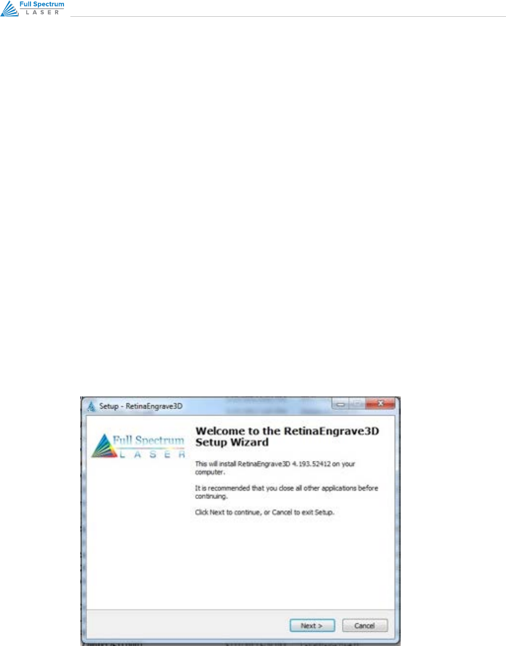
3. Run the executable. Make sure to allow access to the internet and allow the program to make changes
to the hard drive.
7RETINAENGRAVE 3D USER’S MANUAL
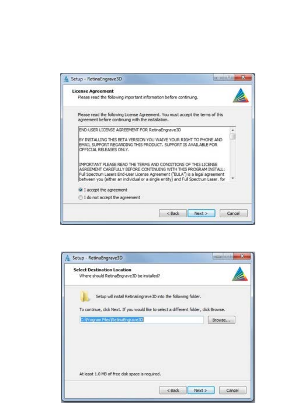
4. Follow the on-screen instructions.
5. Read and agree to the software license agreement.
6. Select a destination folder for the program and its components.
8
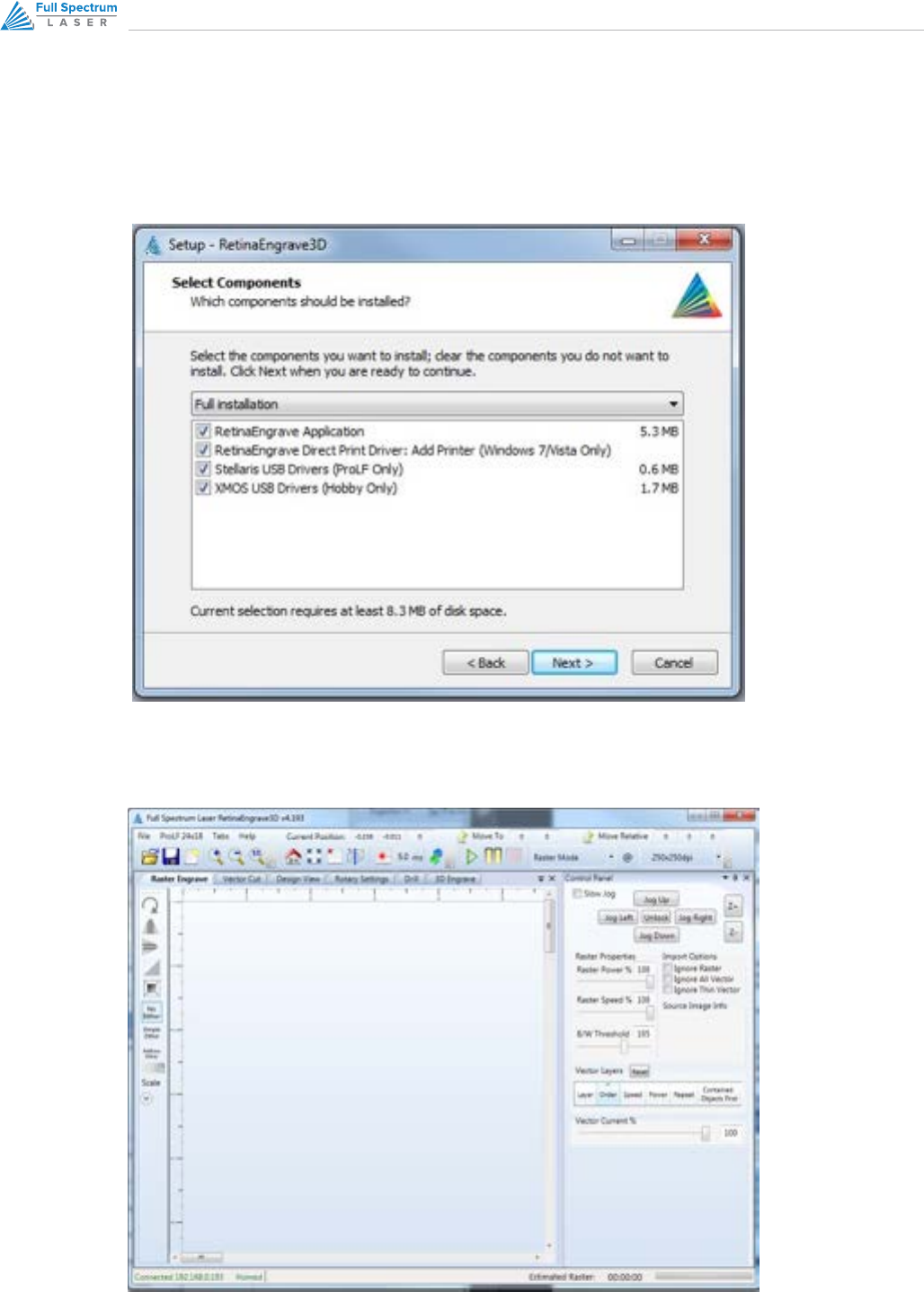
7. Select the type of installation you would like. The Full Installation is recommended.
8. The installation can take several minutes to complete. Once it is finished you will be able to open
RetinaEngrave and make simple designs or start printing to the software directly from other applications.
9RETINAENGRAVE 3D USER’S MANUAL
Network Connectivity
NOTES
Please note that in order for your laser to connect to RetinaEngrave3D, RetinaEngrave must
have networking privileges. You may have to modify the permissions of RE3D in your antivirus
software and/or your Windows security settings to give it explicit permission to access the
network and internet.

10
This section will guide you through the basic functions of your laser
Control Panel
Interface
11RETINAENGRAVE 3D USER’S MANUAL
Overview
Your Laser system is powered by our advanced 3D PRO controller, which can perform basic functions (alignment
and test) without requiring a PC connection. Installation of a microSD card will allow you to permanently store jobs
created in our RetinaEngrave software on your laser and thus free up your PC for more important tasks (like surfing
the internet).
Once you have prepared a job in RetinaEngrave, you can start the job immediately or download the job to the
onboard memory of the laser. To run a downloaded job, there is an additional step of loading the job in the
controller’s memory before pressing “go”. This is done using the LCD touch panel:
1. Press the Mode Select button (FS/Z) until the MODE field reads “FF”.
2. The SELECTION field should read “filename.bin”, where “filename” is the name of the job file you loaded.
3. Press the Start/Cancel button (button 6) to load the job.
4. Press the Start/Cancel button again to run the job.
The LCD touch panel also allows you to control the basic functions of your laser without needing to connect a PC.
This is very convenient during alignment and testing procedures.
NOTES
• If the laser system does not find a DHCP server while booting, it will assign itself an
IP address. This address is displayed on the screen after boot—the self-assigned IP
does not change between power cycles.
• The panel uses capacitive sensing which requires contact with skin to operate.
• The panel is quite sensitive and can often sense changes through thin fabrics
(a cotton shirt). Please take note of this and avoid leaning on the panel during
maintenance.
• The control panel interface is mode-based, meaning that each button’s function
depends on the currently-selected mode.
12
Panel and Display
The LCD screen has two lines and gives operations information in four fields:
• The SELECTION field is located on the top line and gives information on the current operation mode of the
laser
• The MODE field is located on the far left of the lower line and tells the operator the current mode
• The POWER field displays the laser power on a scale of 0-255. During a job you can adjust from 0-255 on
the fly using the up and down arrows. It is located to the right of the MODE field.
• The ADDRESS field displays the last 3 digits of the IP address with a character prefix. A prefix of A means that
the laser did not find a DHCP server on its network and self-assigned an IP addres. The D prefix means the
laser found a DHCP server.
• The POWER field displays the laser current in mA, or “LO” for current less than 1mA. Sometimes this field will
display 1.1mA even when the tube is o; in general, anything less than 2mA is considered o.
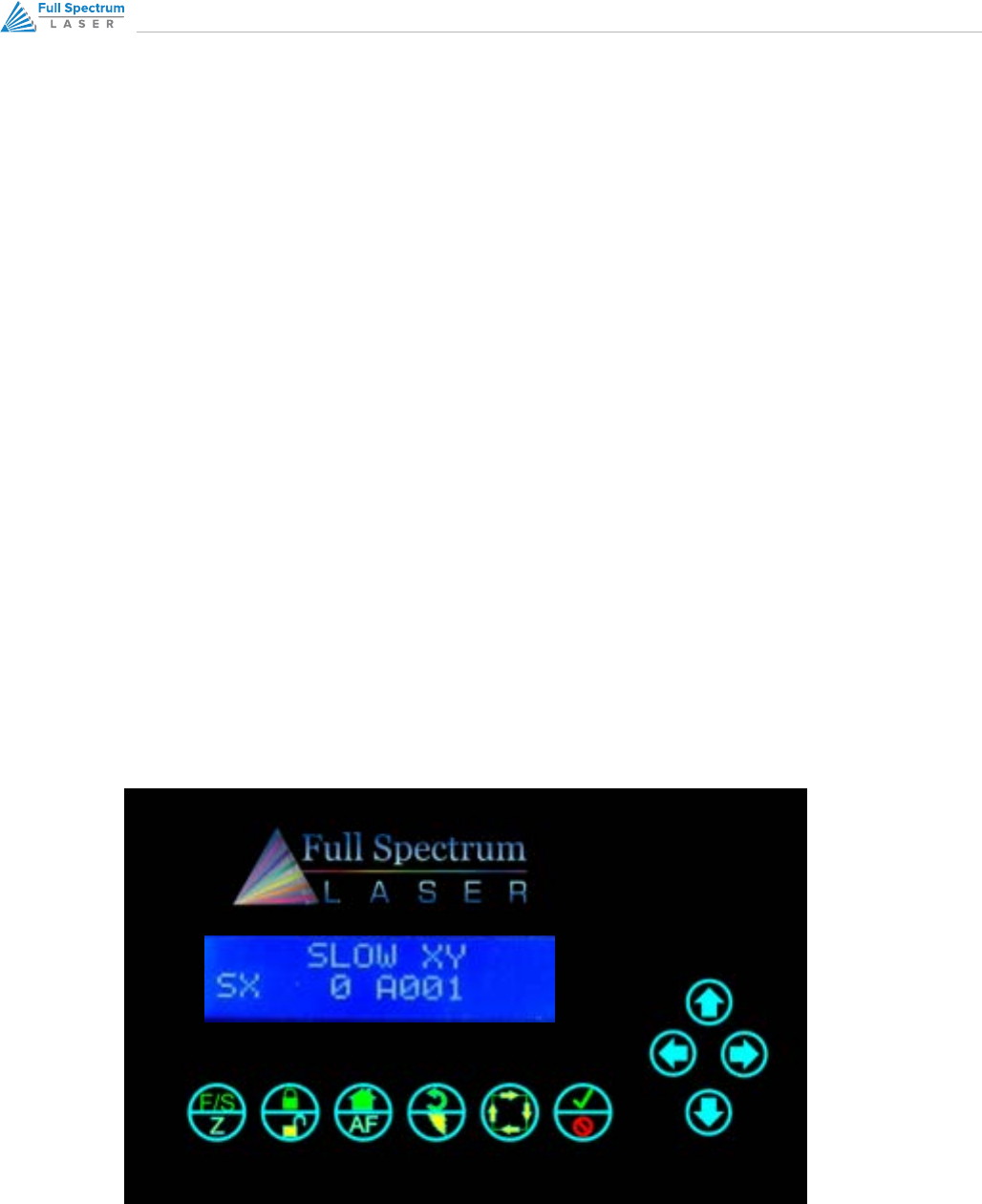
Figure 1 – Control Panel

13RETINAENGRAVE 3D USER’S MANUAL
Button Functions
Panel function buttons are numbered 1-6 starting from the left. Jog buttons (arrow pad) continue the numbering from
7 starting at 12 o’clock and counting up counterclockwise. Typically the icons on the top line are active during Fast XY
Jog (Mode 0). The icons on the bottom are typically active during Alignment (Mode 2).
• The SELECTION field is located on the top line and gives information on the current operation mode of the
laser
• The MODE field is located on the far left of the lower line and tells the operator the current mode
• The POWER field displays the laser power on a scale of 0-255. During a job you can adjust from 0-255 on
the fly using the up and down arrows. It is located to the right of the MODE field.
• The ADDRESS field displays the last 3 digits of the IP address with a character prefix. A prefix of A means that
the laser did not find a DHCP server on its network and self-assigned an IP addres. The D prefix means the
laser found a DHCP server.
• The POWER field displays the laser current in mA, or “LO” for current less than 1mA. Sometimes this field will
display 1.1mA even when the tube is o; in general, anything less than 2mA is considered o.
DURING SETUP
1. FS/Z MODE SELECT
a. Toggles between modes
b. Fast XY Jog (Mode 0) -> Slow XY Jog (Mode 1) -> Alignment (Mode 2) -> File Select (Mode 3) -> Factory
Reset (Mode 4)
2. LOCK/UNLOCK
a. Locks or unlocks the drive motors. System cannot jog or test fire while unlocked, but laser head can be
positioned by hand.
3. HOME
a. If in Fast XY (Mode 0) or Slow XY (Mode 1) pressing this button will cause the laser head to seek the
home position. After homing, the laser will know the position of the head. Unlocking the motion system
causes the unit to forget position (it must be re-homed).

14
4. RETURN/TEST FIRE
a. In Fast XY (Mode 0) or Slow XY (Mode 1) the laser will move to the previously saved job start position.
b. In Alignment (Mode 2) this button fires a short-duration pulse designed to mark thermal paper.
5. RUN PERIMETER
a. In Fast XY (Mode 0) the bounding perimeter of the job will be shown quickly (RetinaEngrave software
must be started/loaded with a job for this function to be active).
b. In Slow XY (Mode 1) the bounding perimeter of the job will be shown slowly.
6. START/CANCEL
a. In any menu mode (File Select or Factory Reset) this button will select the option displayed in the
SELECTION field.
b. Cancels a move operation (homing, autofocus or a running job).
c. In Fast/Slow XY, with the laser UNLOCKED, this fires a higher-power test pulse.
d. In Fast XY, pressing this button after the laser homes will rapidly move the head to the upper left corner
of the workspace.
e. In Slow XY, pressing this button after running a job will allow you to re-run the same job.
7. JOG BUTTONS 4
a. In Fast or Slow XY (Modes 0 and 1), the buttons move the laser head left/right and front/back.
b. In File Select (Mode 3) the up and down buttons scroll through the loaded jobs.
DURING A JOB
1. Only the LOCK/UNLOCK and CANCEL buttons function. All other function buttons are disabled.
a. LOCK/UNLOCK pauses/resumes the job.
b. CANCEL cancels the job.
2. UP/DOWN JOG BUTTONS allow you to adjust the job power on the fly. Scale is from 0 (no power) to 255 (full
power).
15RETINAENGRAVE 3D USER’S MANUAL
MODES
FAST XY JOG MODE 0 AND SLOW XY JOG MODE 1
Use the jog buttons to move the laser head. Press the home button to index the laser head.
ALIGNMENT MODE 2
Use this mode during tube testing and mirror alignment. The test fire button fires a short-duration laser pulse
that will mark thermal paper. Use the jog buttons while the motors are locked to jog the head. Unlock the
motors to move the head by hand. The test fire function is enabled while the motors are unlocked. The test
pulse will not fire with the magnetic safety interlock open.
FILE SELECT MODE 3
Navigate through .bin job files that are loaded on a microSD card (not included). Use the up and down jog
buttons to scroll through the list and press the Start button to load the job. Press the Start button a second
time to run the job.
FACTORY RESET MODE MODE 4
Use this mode to reset the laser’s IP address settings to the factory defaults. Useful if you assign a static IP
but can no longer connect.
NOTES
• The Hobby Laser controller has 2 hard stops and 2 soft stops on the limits of the
axes. Soft stops prevent the motion system from attempting to move beyond its
mechanical limits, but require a reference in order to work: the laser must be homed
in order for the soft stops to function properly.

16
This section will guide you through validating your software
RetinaEngrave 3D
Pro Activation
17RETINAENGRAVE 3D USER’S MANUAL
Overview
Validation Walkthrough for New
Customers
If you are a new customer, your laser’s control card is shipped with an 80-hour temporary usage authorization. If you
are an existing customer, this information will apply if you update your software—after the update you will have 80
hours to activate your card. The 80 hours are only counted while the laser is ON. During the temporary usage period
you must connect your laser to your PC while it is connected to the internet and validate your card. Control card
activation is a one-time process. This section will walk you through the validation process.
1. Connect your laser to your computer (either directly or over the network).
2. Make sure that your PC has a working internet connection.
3. Turn on your laser.
4. Start RetinaEngrave.
5. RetinaEngrave will automatically attempt to connect to your laser. Alternately, you can manually select or
enter its IP address.
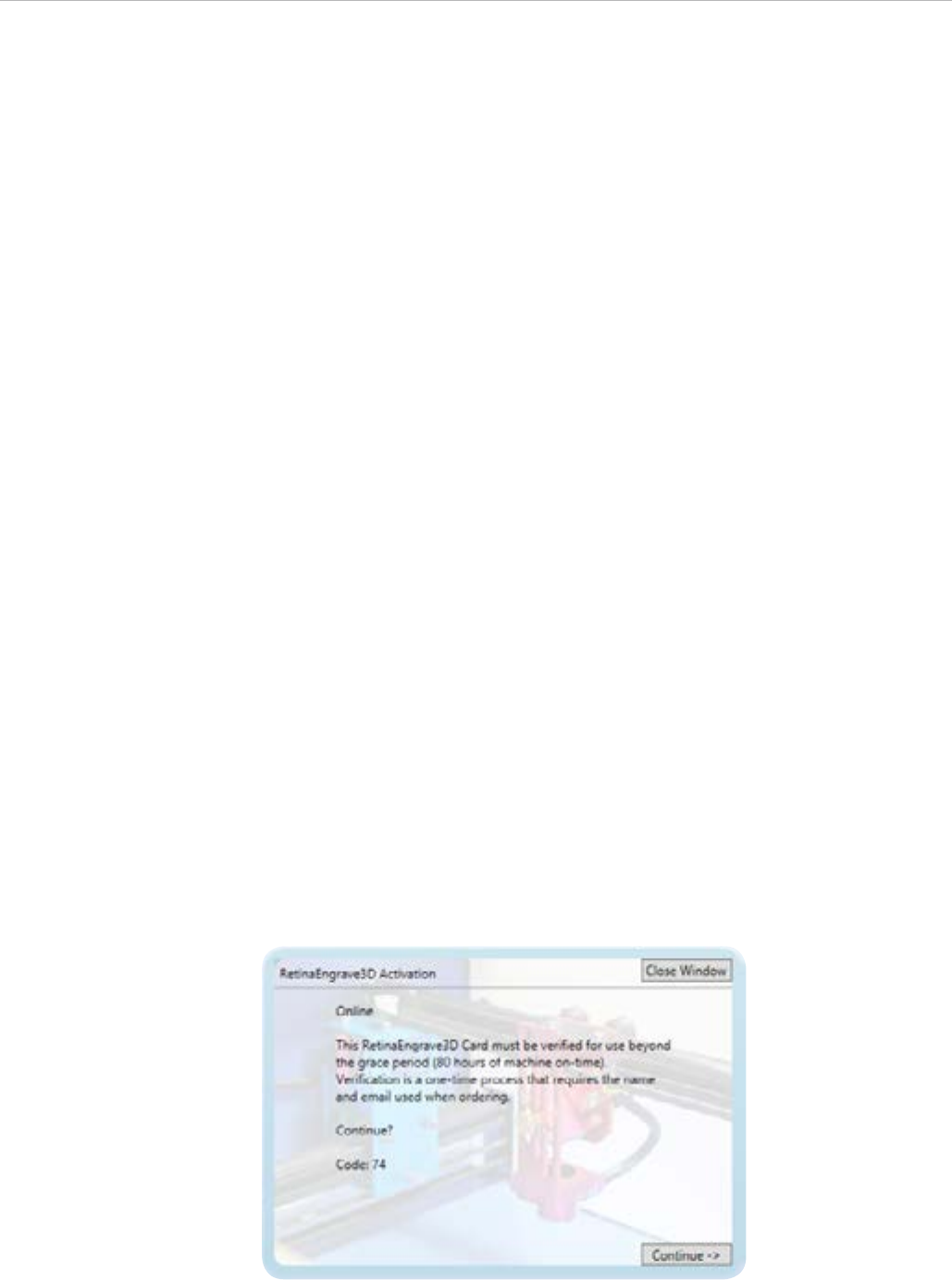
6. Once the laser has successfully connected to RetinaEngrave a popup will appear informing you that your
card is temporarily activated, the amount of hours remaining and will ask you to validate your card.
7. Click “Continue →” to proceed to the validation information screen.
18
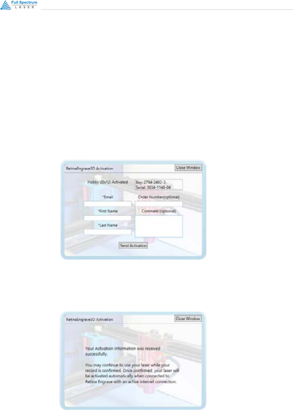
8. Fill out the fields on the validation screen with the requested information. This information should match or
be close to the information you supplied with your order. If it is not, we may need to request clarification from
you. Fields with a * are required.
a. Your order number (optional; 3 or 9 digits, emailed to you from GoogleCheckout).
b. Contact person/company (first and last name).
c. Contact email (this should be one that is regularly checked)
d. Comments field (optional; you can use this to provide extra information, such as a phone number).
Anything you enter into this field will be attached to the record in our database and will be viewed when
we process your validation. This field is also used for communications during the validation process.
9. Once you have entered the information, hit “send”.
10. The information will be sent to us for comparison against your order info.
11. Once your information has been received, you will see the popup message.
12. Once we have verified your information, we will update the record in the database.

19RETINAENGRAVE 3D USER’S MANUAL
13. The next time your laser is connected to RetinaEngrave and the Internet, it will retrieve the updated record
info and your card will be activated.
1. Download the latest version of RetinaEngrave and extract the .zip archive to a location on your PC.
2. You may or may not be required to update your laser’s firmware—open the extracted folder and read any
documents (Text, PDF, Word) found there for installation information. Follow those instructions first (load
firmwares using your current version of RE3D).
3. Run the RetinaEngrave executable installer.
4. Follow the steps in the previous section: VALIDATION WALKTHROUGH FOR NEW CUSTOMERS
1. If you are unable to connect to your laser and the internet at the same time you will need to perform the
following steps to activate your unit.
2. Connect your PC to your laser via Ethernet.
3. Start RetinaEngrave3D and ensure that you have a connection with your unit.
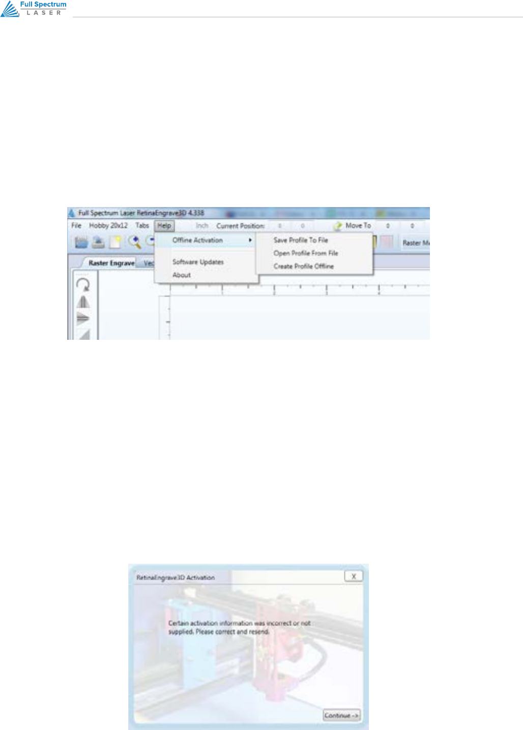
4. Navigate to the Help menu, and select “Create Profile Oine”
5. Again, navigate to the Help menu, and select “Save Profile to File”
6. Choose a location to save your laser’s profile.
7. Connect your PC to the internet and log in to your email account.
8. Attach the laser profile file to a new email and send to activation@fullspectrumlaser.com
9. We will verify that your information matches the purchase, or send you an email if we need more information.
Validation Walkthrough for Existing
Customers (Software Upgrade)
Oine Validation Procedure
20
10. Once your profile has been verified, we will email you an activated profile.
11. Download the activated profile.
12. Start RetinaEngrave.
13. You can drag the activated profile into the workspace, or use the Help menu → “Open Profile From File”.
14. Your laser is now activated.
Figure 2 - Help Menu for Oine Activation
Validation Incomplete - More Information
Required
If the information that you supplied during the activation process does not match any of our records, we will update
your status and the next time that you open RetinaEngrave3D a popup (Figure 10) will appear notifying you that more/
corrected information is required.
21RETINAENGRAVE 3D USER’S MANUAL
1. Pressing “Continue →” will take you to the validation form (Figure 7) that you submitted, with the information
you supplied pre-populated.
2. The “Comment” field is used for communications between you and our support sta. We use it to provide
clarification on the reasons for requesting more or updated info.
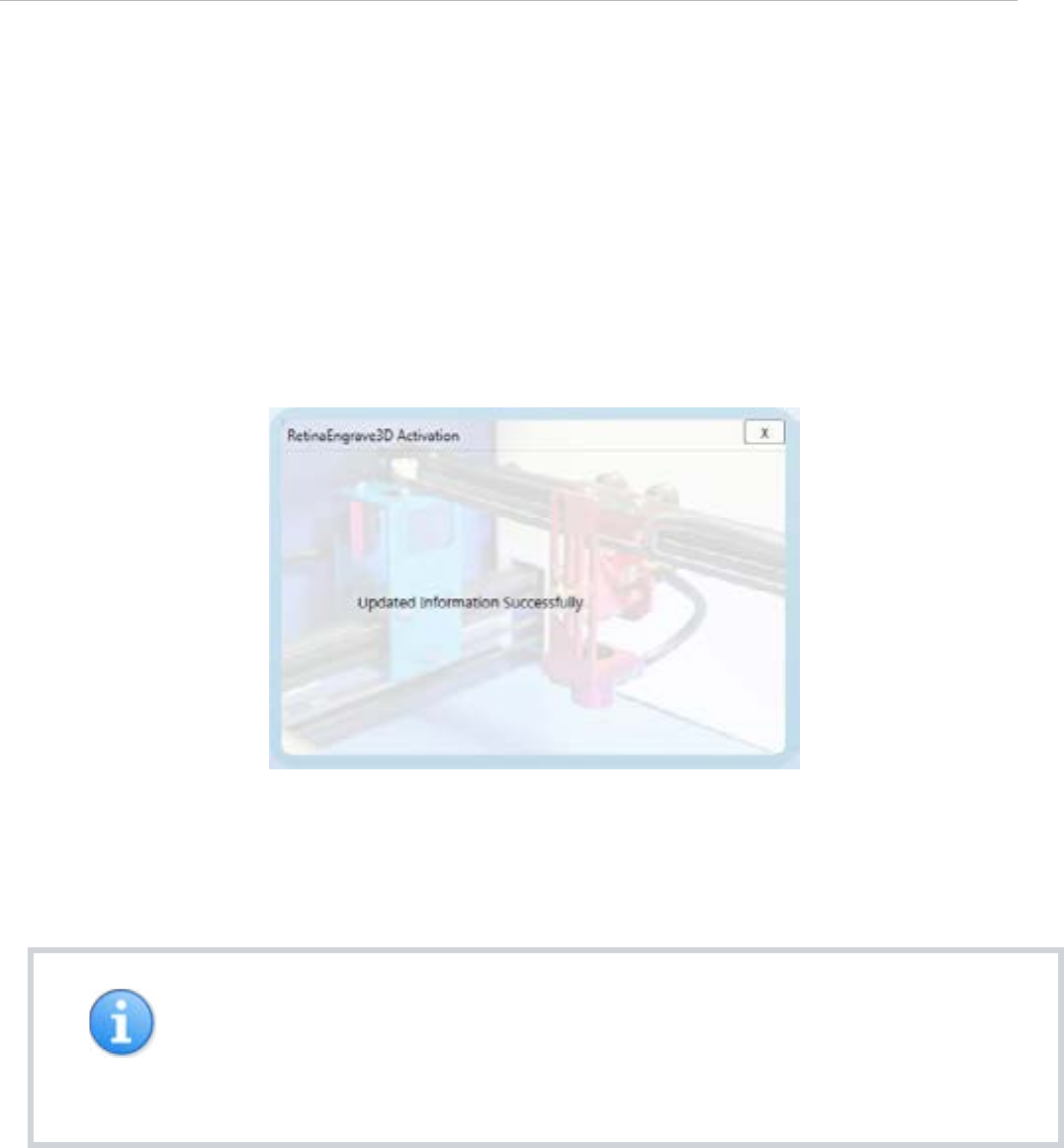
3. Based on the feedback from our sta, update the Validation form and click “Send Activation”.
4. If the update was successful, the popup in Figure 11 will appear. If you attempted to re-submit without
updating your information, you will receive an error message.
5. Once we have received and verified your information, we will update your record and your laser will be
activated the next time that it is connected to your PC and the internet.
NOTES
• If you experience diculties or errors with the validation process, please contact
support via email and include your unit’s serial number and your order number (if
possible).

22
This section will guide you through using the software
Software
Interface

23RETINAENGRAVE 3D USER’S MANUAL
Overview
RetinaEngrave3D is the combination control software, electronics and print driver that allows you to create jobs and
download them to your laser system. The full control package for your laser has four parts:
• RETINAENGRAVE3D PRINT DRIVER
• RETINAENGRAVE3D JOB SOFTWARE
• FSL LCD CAPACITIVE TOUCH CONTROL PANEL
• RETINAENGRAVE3D PRO LASER CONTROLLER
A typical job starts with the creation of a design in your favored software. Once you are satisfied with your work, open
RetinaEngrave3D then your design program’s print dialog. Select the “Full Spectrum Engineering Print Driver”, make
sure that the “Preflight Check” tab is not giving any warnings then click on the “Print” button. Your job is parsed by
RetinaEngrave and will appear in the RetinaEngrave software under the currently selected mode tab. Now you are
able to review your design, make adjustments and choose the laser settings for running the job. You can start the
job immediately or download the job to the onboard memory of the RetinaEngrave controller (if you have installed
a microSD card). To run a downloaded job, there is an additional step of loading the job in the controller’s memory
before pressing “go”. This is done using the LCD touch panel.
RetinaEngrave3D is a powerful program with an easy to use interface. It features standard keyboard shortcuts, which
come in especially handy if you have a wireless micro-keyboard.
NOTES
• The software instructions in this manual are current for Version 4.339
• Hovering the pointer over any button will give you its name and shortcut key.
• RetinaEngrave, like the laser itself, is mode-based. Please note the type of job you
wish to run (Engraving, Cutting, Design, etc) is determined by the currently-selected
tab above the Job View.
• The control panel determines important job settings and allows you to move the
laser head. Keep in mind that each section of the control panel only applies to its
corresponding Job View tab (eg Vector Properties only aect the job in the Vector
Cut tab.

24
GENERAL USAGE
OPEN RETINAENGRAVE BY DOUBLECLICKING THE DESKTOP ICON OR SELECTING IT FROM THE
PROGRAM MENU.
The program must be open at the time of printing from your design software in order to capture the print
stream. Alternately, you can print to an XPS print file while RetinaEngrave is not running and open this XPS file
at a later time to print.
The first time that you open RetinaEngrave, you will be asked to select your laser from a popup menu. It is
extremely important that you choose the correct laser, for example, Generation 5 Hobby 20x12”. Choosing
the wrong laser will cause communication errors and the laser tube will fire continuously. If you select the
wrong laser, use the Laser menu and select “Change Laser” to select the proper unit.
If the connection dialog (lower left of RetinaEngrave) shows the laser as disconnected, make sure the Ethernet
cable is plugged in and power cycle the laser. If there is still a connection issue, go to the laser menu and
manually enter the IP Address displayed on the control panel after boot.
PRINT FROM ANY APPLICATION AND SELECT THE “FULL SPECTRUM ENGINEERING DRIVER” AS THE
PRINTER
Vector mode will only capture Vector output. Vector mode has been tested with many dierent vector
programs such as CorelDraw X5, AutoCad 2011, Inkscape, Adobe Illustrator, Draftsight and more as shown in
our demo videos. However, if you have problems vector printing to RetinaEngrave, use CorelDraw X5. Read
the tips on our forums for how to import most file types such as DXF files into CorelDraw. Raster mode should
print from any program.
SELECT THE MODE TAB VECTOR CUT OR RASTER ENGRAVE
Click on the mode tab that corresponds to the type of job you would like to perform. For engraving, keep in
mind that engraved areas should be black. For cutting, colors (Blk, Red, Grn, Blue, Magenta, Cyan, Yellow)
correspond to individual paths and settings. Use the Control Panel to adjust to power and speed of the job.
PRESS THE “GO” BUTTON TO START CUTTING
This downloads the job to the laser’s temporary memory and starts it. The cutting happens in the background.
While every eort is made to eciently multi-thread the process, avoid memory-intensive tasks while cutting
because the trajectories are calculated on the fly by the software. Also monitor the progress of the cut on the
lower right hand corner.
Using RetinaEngrave

25RETINAENGRAVE 3D USER’S MANUAL
VECTOR MODE
RetinaEngrave generates vector information from .xps files directly. RetinaEngrave is capable of recognizing
up to 7 layers of vector information based on line color; Cut+Engrave operations reserve Black for
engraving. All other file types must be opened in their native application or CorelDraw and sent through the
Windows print dialog. Alternatively, print to the “XPS Document Writer” and open the resulting .xps within
RetinaEngrave.
RASTER MODE
RetinaEngrave can open .xps files and various image formats to generate Raster images for engraving.
However, RetinaEngrave handles 1-bit bitmaps dierently from other formats as it does not rescale a 1-bit
bitmap. In 1-bit mode, 1 pixel = 1/1000 of an inch or 1/500 or 1/250 depending on the selected output resolution.
If the pixel is black it will fire the laser, otherwise it does not fire. 1-bit bitmaps produce the most predictable
output. Other image formats are opened with best-eort conversion and up-scaling. You can generate your
own 1-bit dithered images for grayscale eects. There is a tutorial on using Adobe Photoshop to generate 1-bit
bitmaps on the Full Spectrum Laser forums.
ADJUST THE THRESHOLD TO INCLUDE OR EXCLUDE PORTIONS OF THE DRAWING IN RASTER MODE
When working with a grayscale image, adjust the threshold up or down to alter which portions of the image
you wish to engrave.
RASTER RESOLUTION
DPI (Dots Per Inch) is a measure of the pixel density of an engrave. For example, 1000x1000 DPI corresponds
to 1000 left to right sweeps per vertical inch of an image. Higher DPI settings will engrave more deeply as
the average laser on time per unit area is higher. Engraving at 250dpi will be 4x faster than 1000dpi. We have
found that 250DPI works well for most block/vector engraves and 500DPI works well for image engraving.
NOTES
• The job origin in RetinaEngrave is the upper-left of your design.
• RetinaEngrave does not use a fixed index system: the job origin is the current
position of the laser head, wherever it happens to be. Make sure to position the head
such that your job fits into the workspace and onto your work piece.
26
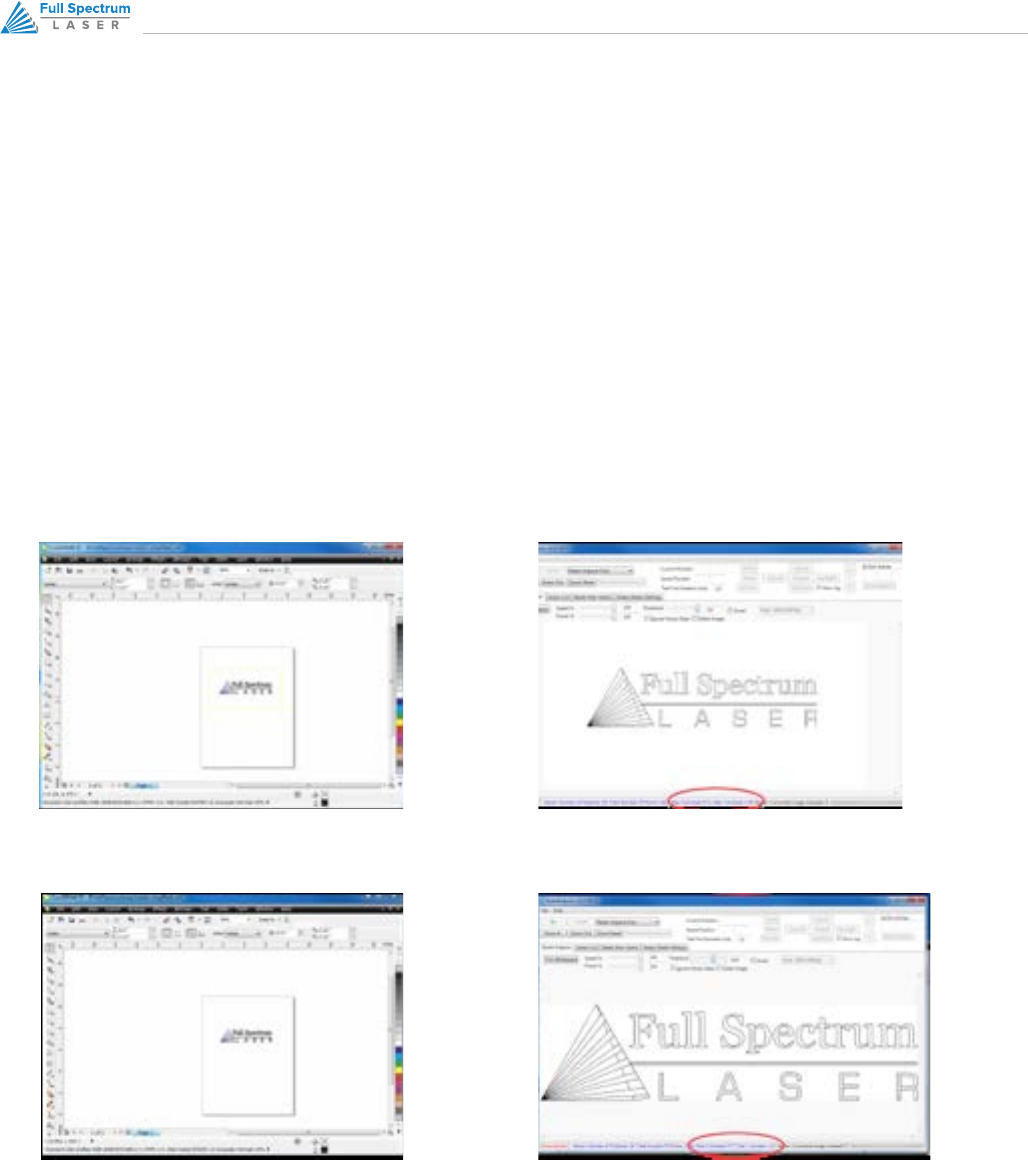
Automatic White Space Cropping
RetinaEngrave automatically crops white space from the page. This allows the use of programs like MS Word where
you cannot set the exact position of the output easily on the page. To prevent cropping, draw a colored rectangle
(yellow recommended) around your objects at the desired output size. In Raster Mode, use the Threshold button to
fade brightly colored lines. In Vector Mode, set the Repeats of the yellow layer to 0 to ignore this line. In Figure 3,
there is a yellow box drawn around the items. When this image is printed, it is cropped to the yellow box outline and
the size is 6.71”x3.48”. In Figure 4, the yellow box is omitted. The image is cropped to the extents of the non-zero
pixels and produces an image that is 4.77”x1.22”.
Figure 3 - Outline Cropping
Figure 4 - Standard Cropping
This feature is particularly useful when trying to align the drawing on existing material. For example, if you have
a 4”x6” wood plaque that you want to engrave, measure the size of the plaque then draw a 4”x6” yellow box this
size in your drawing. Put the text inside this box. Set the position of the laser to the top left hand corner of the wood
plaque and press Start and it will raster the same size and location on the plaque as you have laid out in the drawing.
→
→
27RETINAENGRAVE 3D USER’S MANUAL
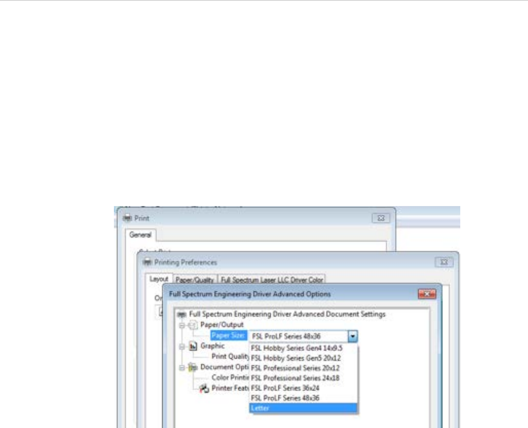
Printing Size
The paper size within the printing options must match the work area of the laser you are printing to. This is done
at time of printing and is independent of the software you are printing from. RetinaEngrave automatically crops all
whitespace from the image so the first non-white pixel is at position (0,0) in the top left.
TO CHANGE THE PAPER SIZE:
• Select Preferences → Advanced and change the paper size.
Figure 5 - FSL Printer Driver Work Area Selection

28
Description of Major Interface Features
Please note that certain advanced features require attachment upgrades to the laser (notably Z axis, autofocus and
rotary functions).
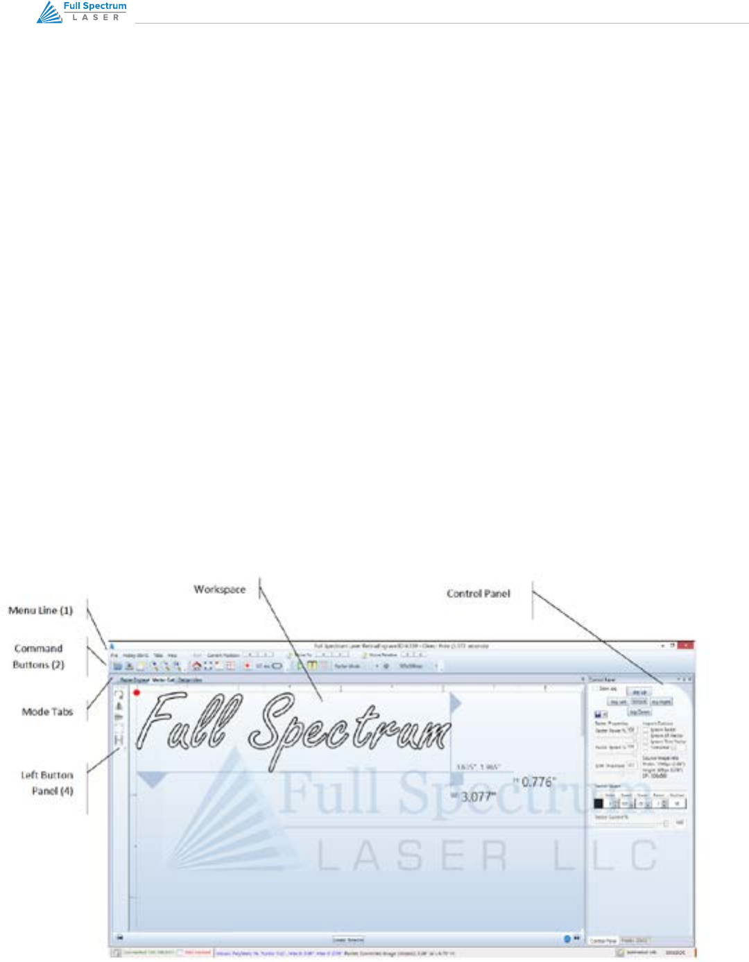
In this section you will be introduced to the major interface features of RetinaEngrave. We will go through the
interface one line at a time from left to right and start at the top (Figure 21). Shortcut keys are bracketed [].
THE WORKSPACE
The workspace is a preview of your current job.
LINE 1
FILE MENU
The File menu allows the user to open up files to engrave. RetinaEngrave supports drag and drop of .xps files
for vector cutting and standard image file types (.bmp, .jpg, .png, .ti) for raster engraving. Other file types
must be printed to the Full Spectrum Engineering Driver or saved as .xps documents.
The file menu also allows a user to load or save a project and settings.
The options sub-menu allows you to save your workspace window setup, set the PC to audibly alert when
a job is completed, enable or disable the keyboard shortcuts, load the last-saved project on startup or log
output for troubleshooting.
LASER MENU
The Laser menu provides options related to the laser unit configuration and communications. It will allow
you to select the type of laser you are connected to, manually reconnect to the laser or manually set the
connection IP address.
The Laser menu also allows you to save the current job and settings as a .bin file onto a MicroSD card (when
the card is loaded onto the laser).
The laser Card Commands sub-menu should only be accessed by direct request and under supervision of Full
Spectrum Laser support sta.

29RETINAENGRAVE 3D USER’S MANUAL
TABS MENU
The tabs menu allows you to show the 3D engrave tab or Control Panel.
HELP MENU
The help menu oers options to inform you about the version of RetinaEngrave you are using, an Activation
menu (future functionality), and Troubleshooting and Update fields which will open the FSL website in your
default browser.
HELP MENU
Shows the laser’s current absolute position from the origin (home; upper right), it is reset to 0,0 when the laser
is homed. The right field is the X coordinate, the left field the Y coordinate.
MOVE TO
The text fields show the saved position read from the controller. The fields are editable, allowing you to
move to a manually entered location. Pressing the Move To button will first move the laser head to the home
switches for reference then rapidly move to the position in the text boxes.
Press the Home button to move the laser head to the origin. The laser will measure the distance it takes
to reach the limit switches and enter the X and Y values into the Move To fields. It will then set the Current
Position boxes to 0,0.
MOVE RELATIVE
These fields command a move by the specified amounts along X and Y using the current position as the
origin. Combine with the Home button to move to fixture points or between fixture points.

30
LINE 2
OPEN FILE CTRL+O
Open compatible file types (.xps, .bmp, .set, .bin).
SAVE PROJECT CTRL+S
Save your current project and settings as a .set file.
CLEAR WORKSPACE
Clear the workspace of the current job.
ZOOM IN +, ZOOM OUT , 1:1 ZOOM
The zoom buttons control the workspace view of the Engrave and Cut tabs. The 1:1 Zoom button restores the
default zoom level.
HOME H
Move the laser head to the origin (upper right of the work area). The laser should be homed after startup or
RetinaEngrave will present a bounds alarm when you attempt to run a job. RetinaEngrave has a built-in bounds
checker to make sure that your design fits within the workspace.
PERIMETER J
The perimeter function will run the laser head in a box that bounds the limits of your design.
PERIMETER STEPS P
Each button press steps through one side of the perimeter bounding box.
LASER HEAD POSITIONING ADVANCED USERS
The default job origin is located at the upper left of your design (0,0 in the workspace) and referenced from
the current location of the laser head in the work envelope. The Laser Head Positioning button opens a dialog
box that allows you to change the default job origin between the center of the job or the upper left (2 radio
buttons in top menu division). The lower division of the Laser Head Positioning dialog box contains 9 radio
buttons that allow you to preview job perimeter positions (you cannot set them as work origins). Keep in mind
that the job origin setting is reset to default when RetinaEngrave is closed.

31RETINAENGRAVE 3D USER’S MANUAL
ESTIMATE JOB TIME
This button calculates the job time based on the current speed settings. The resulting estimate can be found
in the lower right hand corner of RetinaEngrave.
TEST FIRE F AND TEST FIRE DURATION FIELD
Pressing this button causes the tube to fire for the amount of time (in milliseconds) listed in the duration field.
Default value is 5.0ms—this works well for marking thermal paper without burning through. Remember to
close the lid or the tube will not fire.
ROTARY ENGRAVE TAB
Displays the 3D engrave tab.
START JOB G
Press the Start button to start the job with the current settings. The job origin is by default located at the upper
left of your design and is indexed from the current location of the laser head. For example, if you are vector
cutting a 3in square, the laser will fire and move 3in to the right, then 3in forward (down), then 3in left and
finally 3in up back to the starting position of the laser head.
The Start button will be grayed out and not selectable whenever the laser is disconnected.
PAUSE SPACEBAR
Pressing the space key will pause and up-pause the in-progress job.
CANCEL
Immediately ends the in-progress job and returns to the job origin.
MODESELECT MENU
This drop-down menu allows you to select between several modes: Raster and Vector modes open their
respective tabs, Raster then Vector will first run the job in the raster tab (black pixels) and then run the job in
the vector tab.
The Simulate Vector modes create a red-dot overlay in the workspace that follows the path of your vector
lines at some multiple of the currently selected speed (eg 100% speed at 0.5x runs at equivalent of 50%
speed).
RESOLUTION MENU
Drop-down menu where you can select the DPI of the current job. Only used in Raster mode.
32
CONTROL PANEL
The control panel contains 5 sections: Jog, Raster Properties, Import Options, Source Image Info and Vector
Layers.
The Jog section allows you to move the laser head using either the buttons or the keyboard arrow keys. Selecting the
slow jog checkbox jogs the motion system at half of normal speed. The Lock/Unlock button allows you to unlock the
motors to move the laser head by hand—the motors must be locked in order to run a job or jog.
The Raster Properties section allows you to set the power and speed of a raster job, as well as the B/W threshold for
a grayscale image.
Import Options allow you to set conditions under which the print stream from Windows is captured. Ignoring raster
data is useful if you are working with large or complex files and only causes RetinaEngrave to only render outlines
of filled sections. Ignoring vector data is useful when engraving images. Ignoring thin vectors will ignore small lines
within a factor set by the tolerance field.
The Vector Layers section controls the layer order, speed, power and number of repeats for each layer. As discussed
in the General Usage sub-section, vector layers are based on one of 7 colors. The Contained Objects First checkbox
determines the order of cutting within a particular layer.
Figure 6 - RetinaEngrave3D Interface
33RETINAENGRAVE 3D USER’S MANUAL
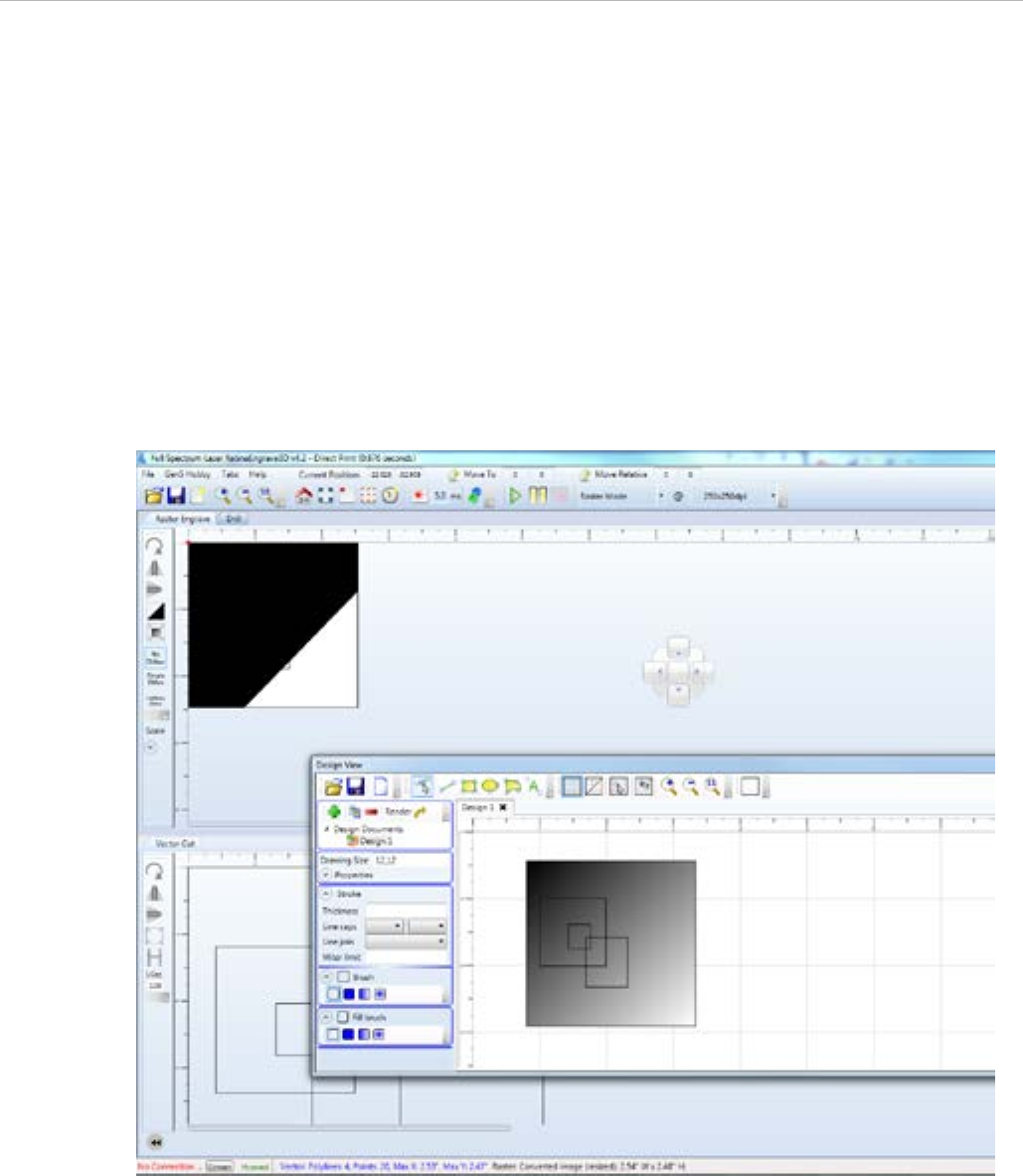
CUSTOMIZING THE INTERFACE
The user interface for RetinaEngrave3D is built around several tabs relating to functionality (Raster Engrave, Vector
Cut, etc). These tabs can be dragged to change their order or location in the program window. You can organize your
workspace using the auto-size function (Figure 7) or leave the tab dialog window floating. The auto-size function will
snap the dragged tab to a preset location in the program window. The default tab location is reached by dragging
to the center of the auto-size overlay. Keep in mind that the Start button will always start a job using the data in the
active tab.
Figure 7 - Customizing the RetinaEngrave3D Interface

34
The proceeding sections will introduce you to engraving with RetinaEngrave3D
Engraving

35RETINAENGRAVE 3D USER’S MANUAL
Overview
Raster Engrave Tab
Your Full Spectrum Laser Hobby Advanced Laser System has several advanced functions that make it easy to bring
your designs from your PC into the real world. Engraving is the process by which complex designs are etched into
a work piece or a work piece is marked using an additive coating such as Thermark™. Engraving can range from a
simple surface mark all the way through deep material removal. Engraving is dierentiated from cutting in that cutting
is the process of burning a closed contour completely through a work piece. The most common type of engraving is
known as “Raster Engraving” or “Rastering”, because the laser fires individual pulses corresponding to pixels in an
image. When the laser is operating in raster mode the head moves rapidly from left to right and slowly top to bottom,
engraving your image pixel by pixel and line by line. You can also engrave images in vector mode (Part 9), by setting
the power such that you score the work piece without cutting through.
Engraving works with both vector and pixel-based source files, allowing you to engrave anything from a simple block
logo all the way through high-resolution photographs. The proceeding sections will introduce you to engraving with
RetinaEngrave3D.
Select this tab before hitting the Start button to Raster Engrave only If your image looks cut o or cropped, be sure to
read Part 7: Working with Projects Larger than 8.5”x11” to learn how to change the paper size in your program. Please
refer to Figure 21 for a visual representation of the Raster Engrave interface.
LEFT BUTTON PANEL TOP TO BOTTOM
ROTATE IMAGE 90 DEGREES
Each button press will rotate the image 90 degree clockwise.
MIRROR IMAGE VERTICALLY
Mirrors the current image about a vertical centerline.
MIRROR IMAGE HORIZONTALLY
Mirrors the current image about a vertical centerline.

36
INVERT IMAGE
Reverses the black and white pixels of the image. Useful for engraving on coated materials.
TRIM WHITESPACE
Use this button to automatically remove additional whitespace in the image after using the Threshold slider.
Usage of this button is not recommended; instead, adjust your design in its native drawing software to
remove items you don’t want to show up on the output before printing. RetinaEngrave automatically removes
whitespace for all non-zero pixels.
NO DITHER
When No Dither is selected, RetinaEngrave will use the threshold slider value to compute a grayscale cuto.
Any grays below the threshold will be black and any above will be white.
SIMPLE DITHER
Dithering a color or grayscale image will produce a pattern of black pixels that approximates the original
gradients. Dithering applies a computed dot density of on/o pixels to the image to create a grayscale eect.
The quality of the dithered image preview in the workspace often looks poor—however, the actual output
engrave quality will be much higher. Dithered images simulate true grayscale by averaging pixel density to
achieve an optical eect closely approximating the original image. Selecting this button has no eect on
images that are 1-bit or black/white already.
HALFTONE DITHER
Like the Simple Dither button, this button dithers the image in the workspace but uses a dierent algorithm.
Certain images and work materials will often respond better to one algorithm or another.
SCALE IMAGE
The Scale dropdown allows you to scale a design before engraving. Set the scale factor in the field and apply
it using the set scale button.

37RETINAENGRAVE 3D USER’S MANUAL
RASTER PROPERTIES AND IMPORT OPTIONS CONTROL PANEL
RASTER POWER %
This field and slider allow you to set the firing current as a percentage of the maximum as set in the
configuration file. Laser tubes have a minimum activation current; setting this value too low will result in the
laser not firing. Keep this in mind when setting power below 10%.
RASTER SPEED %
Set the engraving speed as a percentage of the maximum. Maximum speed is set in the config.xml file. The
raster routine in v4 is optimized so it only rasters non-whitespace and minimizes the acceleration distance. If
you set the speed % very low such as 1% then the laser head does not need much acceleration distance. Total
time to engrave = (acceleration time + raster time). Since acceleration time is also lower the total time is not
linearly related to the speed %. However, the energy/heat applied to the material is linear according to the
speed %. For deeper engraving use a slower speed.
BLACK/WHITE THRESHOLD
Adjust this slider to fade in or fade out portions of any image that is not black/white. Your computer graphics
card must be fast enough to use the slider in real-time to see the updates. This has no eect on 1-bit bitmaps
or black and white images. If you have a computer with a slow graphics card, set the threshold using the text
box and enter the values manually.
IGNORE ALL VECTOR
Checking this box will only import raster data and ignore vector data. When processing a print job,
RetinaEngrave attempts to sort all the vectors for the fastest cut times. A drawing containing millions of
points or vectors will take up a large amount of memory and CPU which can cause a major slowdown in
performance. Ignoring the vector data will also allow faster print jobs if only raster is required.
38
DPI Selection
Full Spectrum Laser recommends settings of 250x250dpi for most applications; text as small as 4pt can be engraved
at 500dpi with excellent readability. Typically, 1000dpi is only used special cases. The dpi setting also aects the
delivered power density, as higher dpi settings correspond to a higher number of pulses per square inch. It is
also important to note that due to the focused beam spot size (0.002-0.005in) there will be pixel overlap at higher
dpi settings. This leads to a blending eect in the overlapped areas, which will lead to a darker engrave result on
particular materials (woods).
The dpi settings aect the print processing resolution. The maximum printing resolution is set in the configuration file
and displayed in the control panel in the Source Image Info box. The final resolution is set to the maximum of the
configuration file setting and the dpi selected from the dropdown menu. The default setting is 250dpi. By selecting
1000dpi before printing, the laser will import at 250dpi then upscale the image using a bi-cubic interpolation to
1000dpi.
RetinaEngrave stores the source image in memory and converts it to grayscale before dithering. Due to the large
number of pixels in a 1000dpi image (1 million pixels per square inch) your computer may run out of memory.
Computers with less available memory should select 250dpi before printing because even at an input resolution of
500dpi the memory requirements can be high.
IMPORTANT NOTE: POSITIONING WHEN RASTER ENGRAVING
When you raster an image, the laser head accelerates to the desired speed over some at the
default job origin—if you are using a changed origin, for example a center origin, the laser
head will still move to the upper left corner before beginning the job.
Because of the acceleration and deceleration distances, some jobs will require a 1in buer on
the left and right sides to avoid crashing the laser head..

39RETINAENGRAVE 3D USER’S MANUAL
Getting Better Raster Results
A laser has two states: on and o. Every black pixel or “laser dot” is the result of the laser turning on and firing at a
particular location. This location is controlled by the input image, which can be thought of as a “map” of on and o
pixels. The question is how do we give RetinaEngrave the best “map” of these laser dots to accurately represent the
original image?
Your source image is processed several times between sending it to the Windows XPS Image Writer (printer) and final
laser processing of the work piece. The first alteration of the source image occurs when the image is sent from the
print stream into RetinaEngrave. If the printer DPI is set dierently from the software DPI, the source image must be
up-sampled to the native DPI of the laser; up-sampling is necessary to keep the output image dimensions (in inches)
the same as the source image dimensions. This process generates new pixels; unfortunately there are mathematical
constraints on the sampling process so it is imperfect.
In order to avoid introduction of error through up-sampling, the source image must be a 1-bit image. 1-bit images are
an exact “map”; all pixels are either on (black) or o (white). The best results are achieved by creating/converting a
source image in a dedicated editing program with DPI settings that match the native DPI of the laser (1000dpi).
In the case of non 1-bit .bmp images (greyscale/color), dimensions are set on import using the page size in the
print driver dialog box. Changing the DPI setting results in a dierent number of pixels in the same space, without
changing the dimensions of the image. This procedure results in lower output quality that is not true to the source
image. Multi-bit images that are not evenly divisible by the native laser DPI (250/500/1000) should always be direct
printed instead of dragged and dropped, and should be rastered at the same resolution as they were printed. The
case study in the following section examines the results of various import methods.
40
SOURCE TYPE IMPORT METHOD NOTES
1bit BMP Drag and Drop, File-Open
Pixels are divided by laser dpi (1000 for hobby). 1000=1
inch. DPI box changes DIMENSIONS of output by skipping
lines. Output is always true to source. It is not recommend-
ed to Direct Print 1-bit images
Color/Greyscale BMP Direct Print
Always Direct Print non 1bit images as they are sampled at
a rate proportional to laser output resolution, resulting in
better quality output. For best output, Raster at the same
DPI as the source image
XPS file containing images Drag and Drop, File-Open,
Direct Print For best output, Raster at the import DPI
Summary of Best Practices for Image Formats
41RETINAENGRAVE 3D USER’S MANUAL
Case Study: The Eects of Up-scaling
Following Direct Print
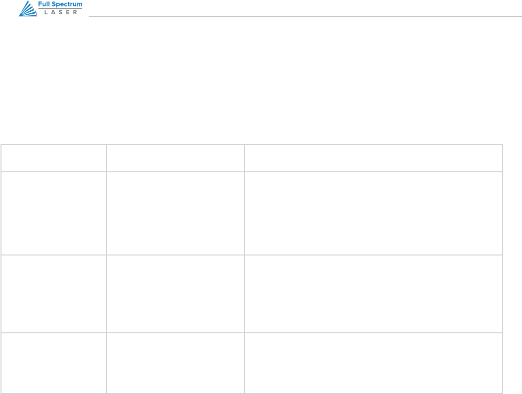
We have generated a small 50x50 pixel box. In the following illustration, the center box is the original size. This is
direct printed using “Half Page” format from Windows Picture Viewer. Figure 8 is the actual size of what is generated
from Direct Print. Figure 9 is the result of a Direct Print at 250dpi. Observe the rounded edges due to the drastic
increase in size.
Figure 8 - Direct Print Source
Figure 9 - Direct Print at 250dpi
42
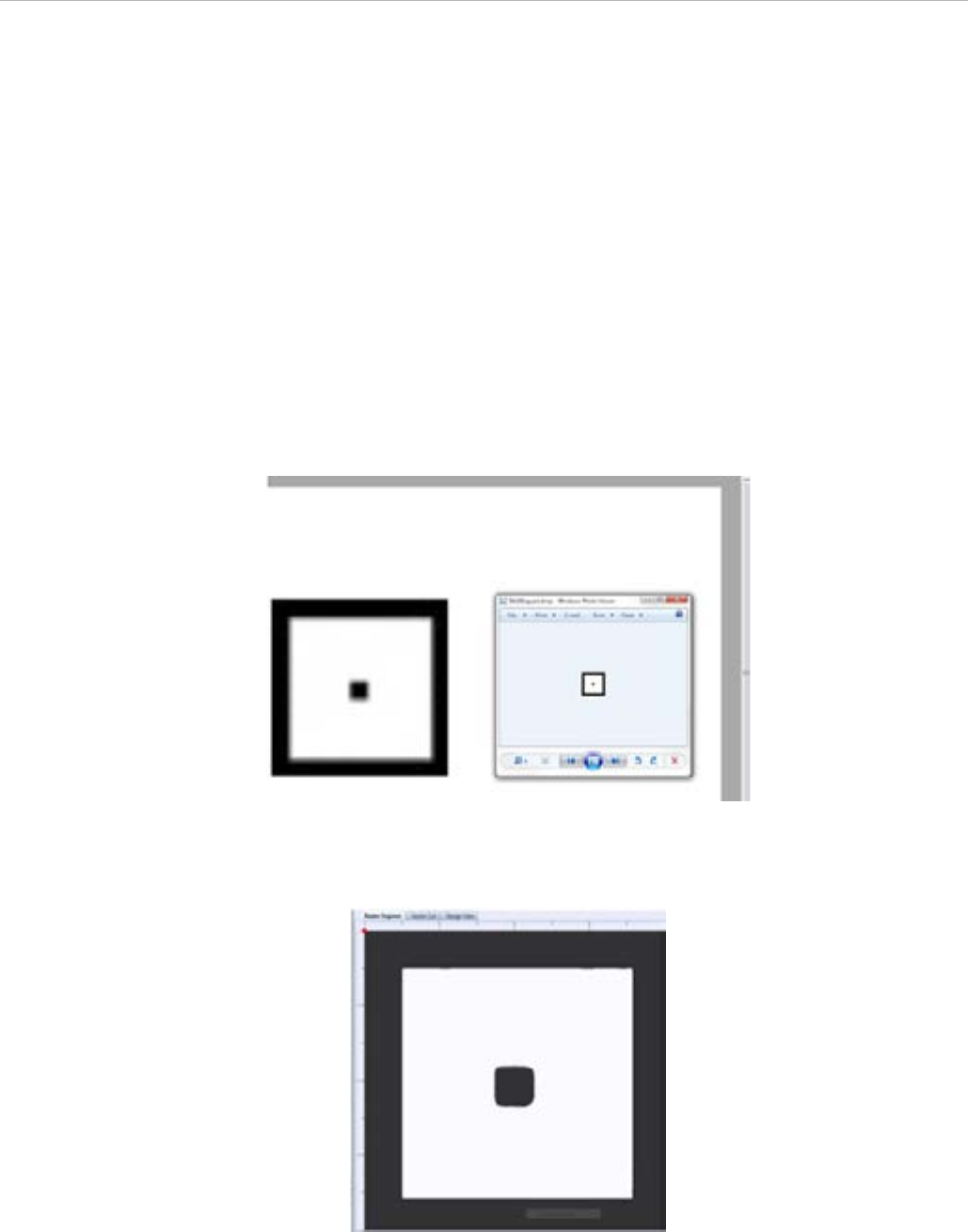
Figure 10 – 1000dpi Output from 250dpi Print
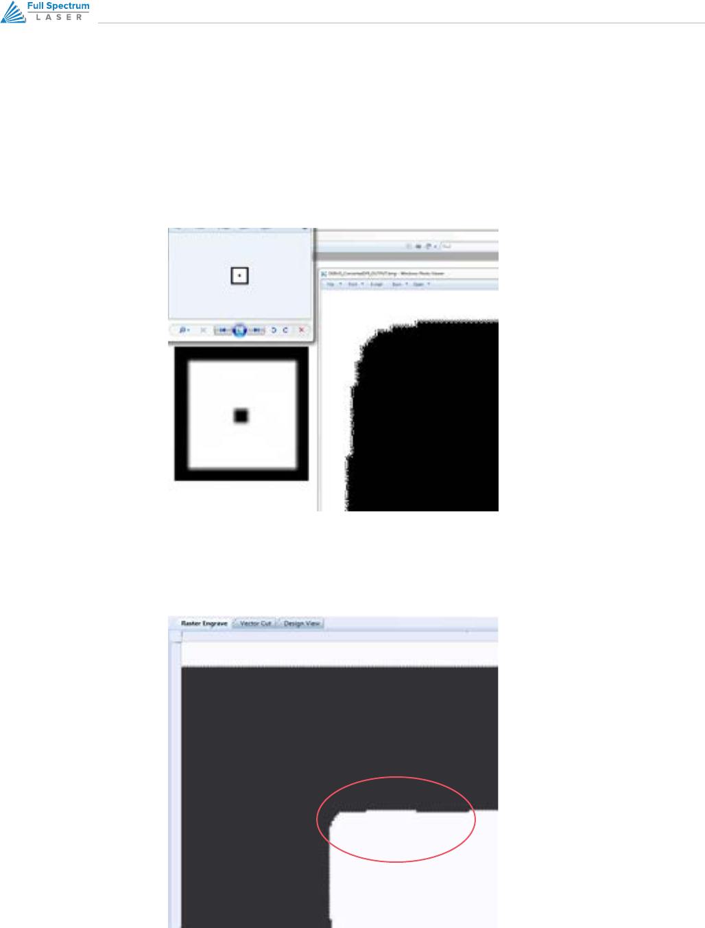
Figure 11 – 500dpi Output from 250dpi Source
If we select 1000dpi within RetinaEngrave and then Raster, we get surprising results. The right image in Figure 10 is
the actual output that is sent to the laser, including the anomalies along the edge. This is the result of direct printing
from a small source to a large output and rastering at a much higher DPI than the project was direct printed at (1000
vs 250).
In Figure 11 we take the corner of the same project and output it at 500dpi instead of 1000. The eects are still visible
although not as severe as using a 1000dpi output.
43RETINAENGRAVE 3D USER’S MANUAL
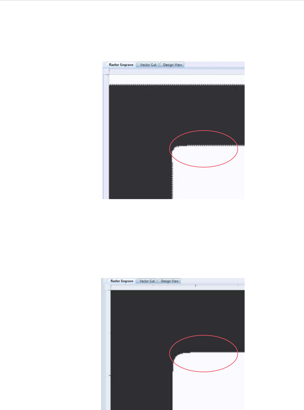
Figure 12 – 250dpi Output from 500dpi Source
Figure 13 – 250dpi Output from 250dpi Source
Figure 12 shows a Direct Print at 500dpi with output at 250dpi.
When we print at 250dpi and output at 250dpi, we find the best results because import and output DPI are identical
(Figure 13). The software must up-sample to 1000dpi in order to lase, resulting in an image ¼ the size of the original.
In order to output at the same dimensions as the source, the software skips 4 lines for every line of output on the
Y-Axis. In this way, no scaling is required and no anomalies are introduced as pixels need not be generated before
output.

44
The proceeding sections will introduce you to cutting with RetinaEngrave3D
Cutting
45RETINAENGRAVE 3D USER’S MANUAL
Overview
In Vector Cut mode, RetinaEngrave receives information from the print stream and interprets it as a series of paths
for the laser head to follow. In order for the print stream to have vector information, the file being printed must be
a vector file. RetinaEngrave is capable of following complex contour paths created in any vector drawing program,
however certain programs and formats are more reliable than others.
Full Spectrum Laser carries out unit testing using CorelDraw X5 and recommends that Hobby Advanced owners use
this program. If you use dierent design software and run into a problem with the print interface, we recommend
printing to the XPS Document Image Writer or saving as a PDF. PDF files save vector information and are the best
way to carry artwork from a non-compatible operating system (Mac or Linux) onto your Windows 7 PC.
Limited testing has been carried out with CorelDraw X6 and it appears to be a good choice as well. Other popular
packages include Adobe Illustrator, Inkscape and Google’s free online vector drawing application. Additionally, most
CAD packages are able to output drawings in a vector format for printing; Autodesk 123D is particularly interesting for
its cost (free) and built-in 3D slicing capabilities.
NOTE:
The Microsoft XPS Document Writer creates images so that they will print exactly as they ap-
pear on your screen. Any program that is vector based will have its information embedded as
vector paths (CorelDraw, MS Word, CAD programs, etc) and should work with the Vector Cut
functionality of RetinaEngrave3D.
46
Vector Cut Tab
Select this tab before hitting the Start button to cut the paths displayed in the work area. If your image looks cut o or
cropped, be sure to read Part 7: Working with Projects Larger than 8.5”x11” to learn how to change the paper size in
your program.
Figure 14 – Vector Engrave Interface
Figure 15 - Vector Cut Path Selection

47RETINAENGRAVE 3D USER’S MANUAL
LEFT BUTTON PANEL TOP TO BOTTOM
ROTATE VECTOR 90 DEGREES
Each button press will rotate the design 90 degree clockwise.
MIRROR VECTOR VERTICALLY
Mirrors the current vector drawing about a vertical centerline.
MIRROR VECTOR HORIZONTALLY
Mirrors the current design about a horizontal centerline
RESIZE VECTOR ACCORDING TO INPUT VALUES
This button will bring up a dialog box allowing you to change the size of the vector image in the workspace by
setting specific X and Y dimensions. It does not preserve scale.
HORIZONTAL VECTOR HATCHING
This button and corresponding parameter box automatically fill closed contours with a horizontal hatch
pattern, with the gap between horizontal scan lines (in inches) determined by the input in the parameter box.
This is a useful function for engraving deeply into an object—with the proper settings it will remove material
much more quickly than in Engraving mode. Be aware that due to the scan gap being non-zero the bottom
surface might not be smooth.
VECTOR LAYERS, VECTOR CURRENT % AND IMPORT OPTIONS
IGNORE RASTER
Select this option to speed up processing of large vector files on computers with limited memory. Raster data
is memory intensive for large drawings at the highest resolutions and is unneeded if only vector cutting is
required.
VECTOR CURRENT %
Total power is determined by a combination of delivered current and voltage to the laser tube. The current is
directly regulated while voltage is controlled by PWM (Pulse Width Modulation). PWM is a technique whereby
an average voltage is delivered in a series of pulses per unit time. In Vector mode you can control both the
PWM frequency (power) as well as the delivered current (Vector Current %). In Raster mode, the output is
pulsed based on the speed and pixel pattern, so only current control is available (Raster Power %).

48
VECTOR LAYERS
RetinaEngrave automatically separates vector drawings into layers by color. Each layer can specify dierent
properties. The Reset Layer Properties button will reset the Vector Layers table to the default values.
• Layer: The designated color of the layer
• Order: Layers are cut in order from 1 to 7
• Speed: Sets the speed of the layer as a percentage of the maximum value.
• Power %: Sets the PWM frequency. PWM power control is very fine. Setting it to 0.5% will mark but not cut
through paper.
• Repeat: Set the number of repeats of the layer at the chosen power and speed settings. Set to 0 to ignore
the layer.
Designating Layers
Designating a color to objects/ layers you want to vector cut enables you to take advantage of RetinaEngrave3D’s
ability to specify cutting order, cut speed, laser power and number of repeats for each layer.
RetinaEngrave supports up to seven standard color layers for maximum program compatibility: Black, Blue, Red,
Magenta, Green, Cyan, and Yellow from the RGB color palette.
RetinaEngrave uses a best guess color round o routine when a color is not a standard RGB color. Avoid Black
whenever possible because this is the default color RetinaEngrave uses whenever it cannot figure out what color it
should be. By avoiding Black, you will have more control.
49RETINAENGRAVE 3D USER’S MANUAL
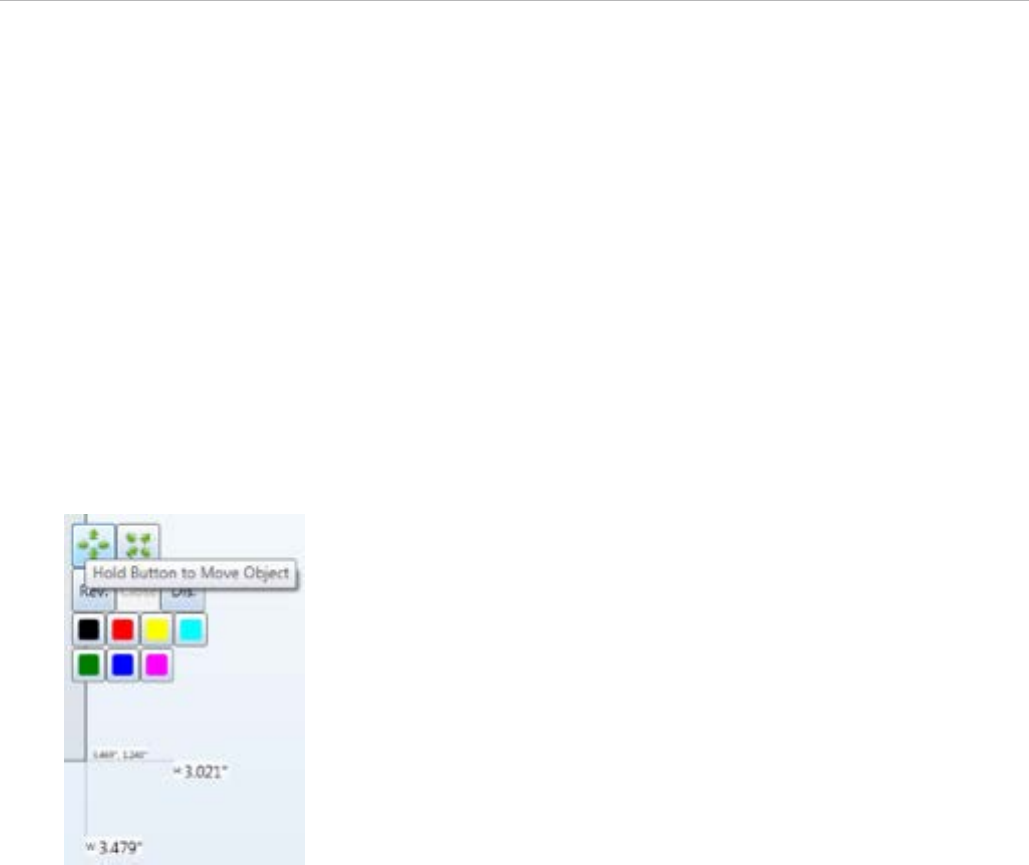
Workspace Tools
Use the drag handles located on the edges of your design to resize the image. The extension lines display the width
and height of the bounding box that encloses the image. Dragging the square handle will preserve the design’s scale.
The small field located on along the height extension line gives the current X and Y workspace coordinates of the
mouse.
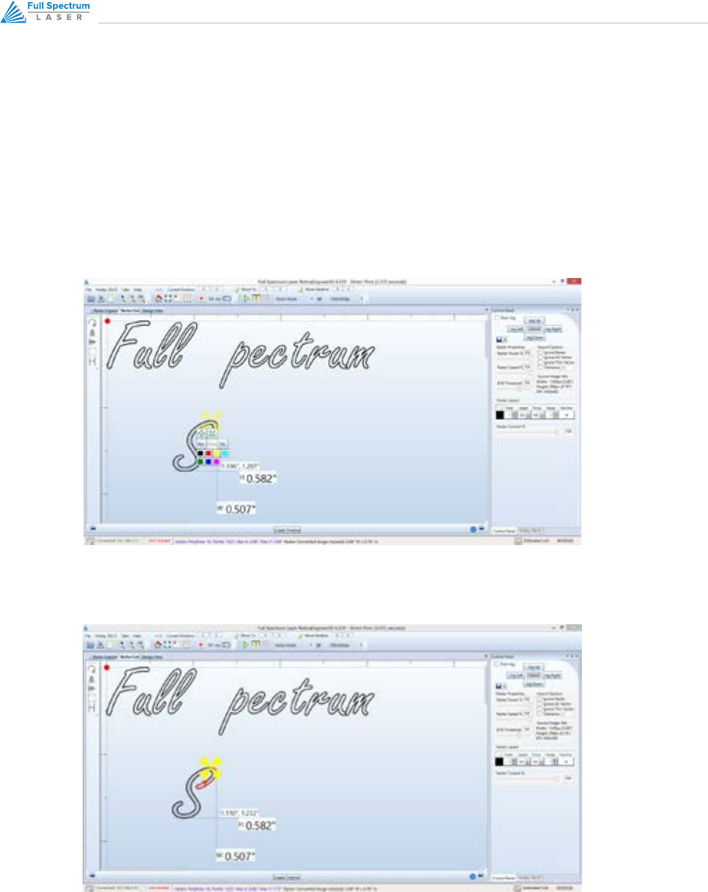
Hovering the mouse over a vector object (poly line) will cause it to highlight. You can right-click the mouse to disable
that object in the current job and right-click again to re-enable.
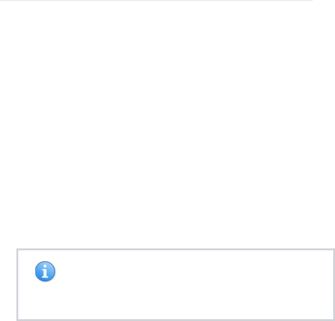
Clicking on a poly line will bring up the workspace editor. You can move, scale or
disable it; assign it to a layer using the colored buttons; reverse the direction of the
path; or close small gaps between the ends of an un-closed poly line (for advanced
users).

50
This section introduces you to the advanced capabilities of RetinaEngrave3D
Advanced
Functions
51RETINAENGRAVE 3D USER’S MANUAL
Overview
Engrave then Cut
The following sections introduce you to the advanced capabilities of RetinaEngrave3D. Some of these capabilities are
only possible with the purchase of extra attachments (rotary engraving). Please make sure that you are familiar with
the previous sections of this manual before working with the advanced functions.
• Combined Engraving and Cutting allows you to set up a job to engrave a design and then cut a pattern
• The Rotary Engraving tab is the interface for setting up a raster job to be engraved on the outside of a
cylindrical object (requires rotary attachment)
• The 3D Engraving tab allows you to take a grayscale image and set up a job that will convert it into an
automatic series of layers to achieve a 3D eect
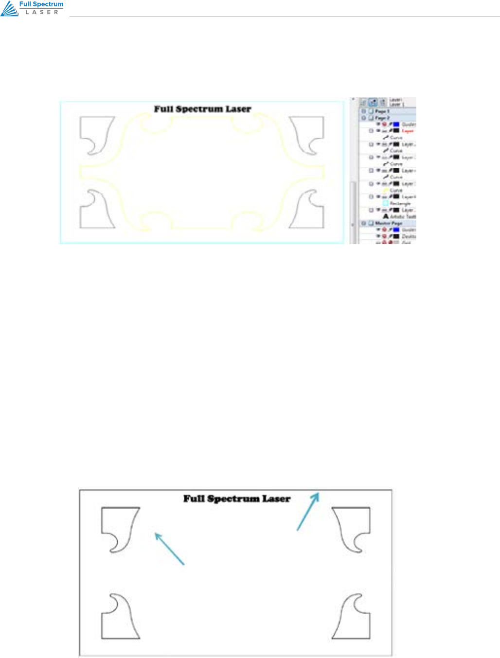
RetinaEngrave3D supports engraving and cutting in the same job. In this section we describe the process of using
CorelDraw X5 to properly prepare your image before direct printing to RetinaEngrave
1. Designate either yellow or cyan to the layers you want to vector and designate black to the layers you want
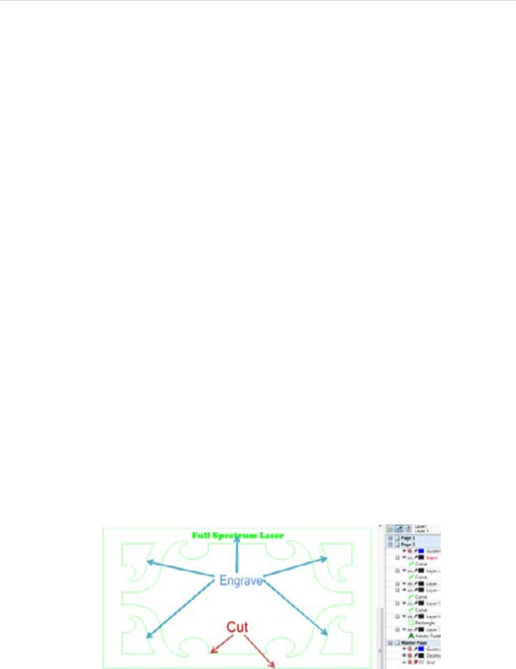
to raster.
2. In our example image we want to
a. Engrave the text and the four corner objects in raster mode by changing them to black.
b. Cut the middle object and the outside border in vector mode by changing them to yellow or cyan.
Figure 16 - Engrave/Cut Example Source
52
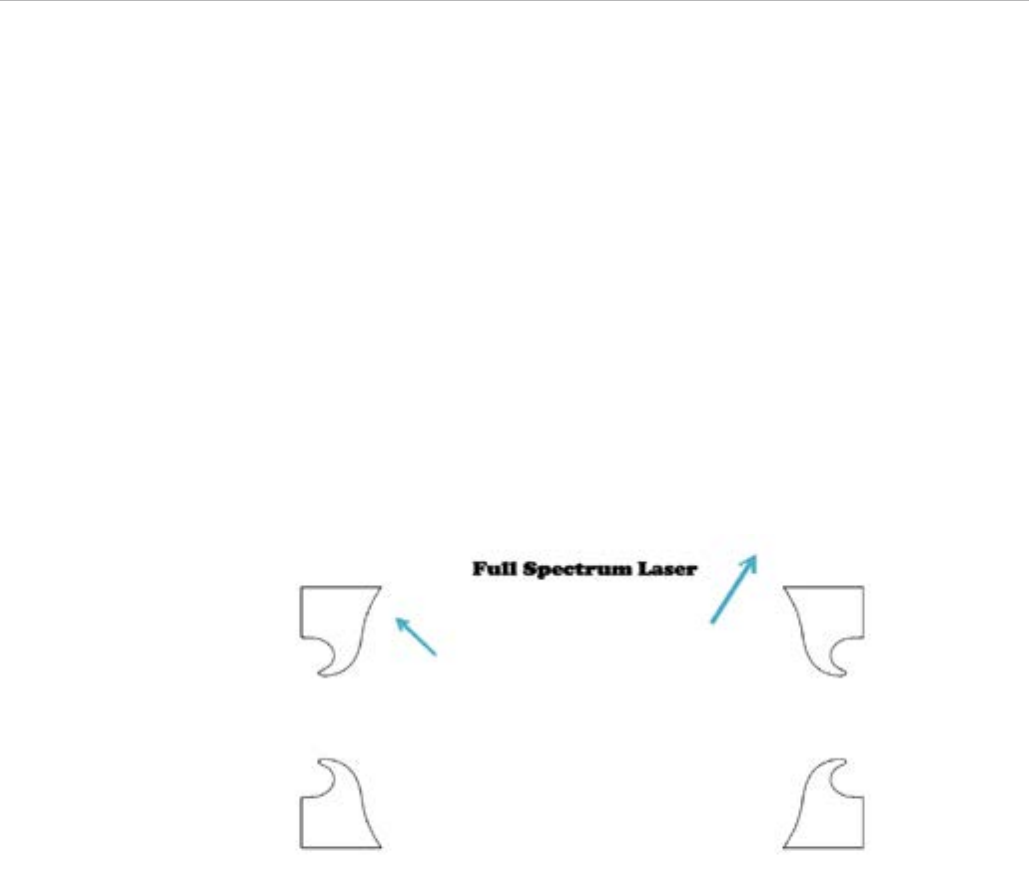
Figure 17 - Engrave/Cut Ready for Direct Printing
Figure 18 - Yellow Layer After Threshold
Make sure that any text that is “Artistic Text” in CorelDraw X5 has a Hairline outline applied.
1. Verify that RetinaEngrave is running in the background.
2. File → Print using the Direct Print Driver.
3. Switch the current program view to RetinaEngrave.
4. Use the mode select drop-down menu to choose Raster then Vector mode.
5. Adjust the slider on the the threshold setting to fade out/in objects. RetinaEngrave will only raster what is
visible on the screen. Adjusting the slider to the left will fade out objects, while sliding to the right will fade in
objects. You can also adjust the threshold by manually typing a value into the box next to the threshold slider
between 0.000 and 1 and then left clicking on the image. The maximum threshold value of 1 will make the
53RETINAENGRAVE 3D USER’S MANUAL
image solid black and should not be used. For optimal results first adjust the threshold almost all the way to
the right to a value of 0.999.
6. Slowly adjust the threshold setting to the left until the vector objects that you previously designated yellow
and/or cyan in CorelDraw X5 completely fade out, leaving only the black raster objects visible.In our example
image we found that a threshold setting of 0.96 made the center yellow vector object completely fade out.
The cyan vector border has not faded out and further threshold adjustment is needed.
7. Further adjustment of the threshold to the left to a value of 0.9 makes the cyan vector border completely
fade out. The threshold for our example image is now properly adjusted leaving only the black objects that
we want to raster engrave visible. The end goal when adjusting threshold value is to adjust the threshold to
the left just enough to make the yellow/cyan objects fade out while leaving the black raster objects highly
visible for optimal detail raster engravings.Threshold settings for your particular image could vary from our
example image settings.
8. Adjust the Speed % and DPI to your desired settings.
9. Left Click on the Start button to engrave your material.
When the raster engrave process is complete DO NOT move your material inside the laser cabinet. Both Raster
Engrave mode and Vector Cut mode use the same job origin. As long as the material has not been moved between
the raster engrave process and vector cut process the image will line up correctly on your material after finishing the
vector cutting process.
54
Rotary Engraving
If you have purchased a Hobby Advanced Rotary Attachment, the following instructions explain how to set up a job
for rotary engraving/cutting.
1. Connect the rotary attachment in your laser system. Setup and installation information for the rotary
attachment is found in the Hobby Laser User’s manual.
2. Turn your laser on and connect to it with RetinaEngrave3D.
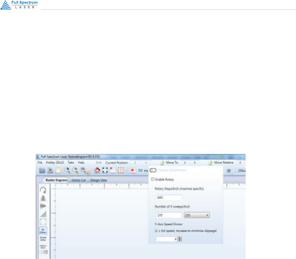
3. Click on the Rotary button and check the Enable Rotary checkbox.
4. Steps per Inch is pre-set—do not modify.
5. X Sweeps per Inch is automatically set based on the DPI settings.
6. Test your job at 0 power to make sure there is no slippage; increasing the value of the Y-Axis Speed Divisor
will help eliminate slippage.
7. Click on the Start button to rotary engrave.

55RETINAENGRAVE 3D USER’S MANUAL
3D Engraving
RetinaEngrave3D allows 3D engraving from grayscale images by automatically separating an image into layers and
allowing those layers to be run as independent raster jobs.
1. Load a grayscale image and then open the 3D Engrave tab.
2. Using the slider or data field, choose the number of frames that you wish to engrave.
3. Right-click on the Auto Generate Frames button.
Your job is broken into a series of frames using the currently-selected Raster Properties. Each frame auto-thresholds
your image by pixel darkness based on the number of frames that you chose. You are then able to do the following:
• Select separate power and speed settings for each frame
• Copy or delete frames
• Drag frames to re-order them
• Adjust the threshold of each frame (high, low and range)
• Set the Z axis oset of each frame (only works with a powered Z table)
You can clear the workspace using the Clear Frames button or Start 3D Engrave to begin the job. Keep in mind that
3D engraving works as a series of individual raster jobs for each frame; as such jobs with more frames can take a
long time to complete.
56
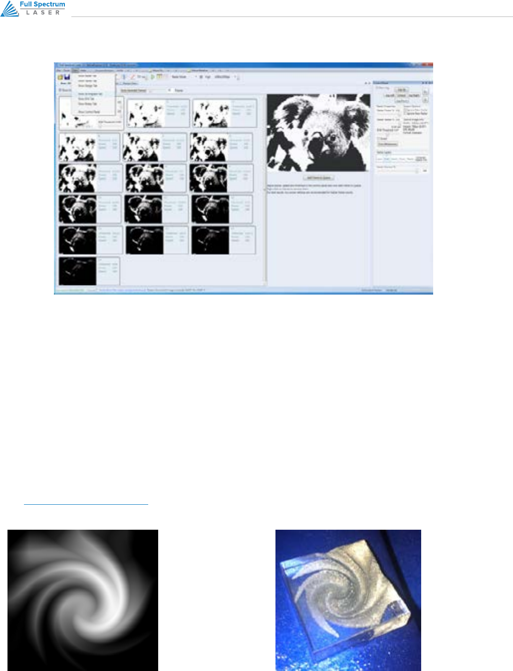
Figure 19 - 3D Engrave Tab
Figure 20 - Example Grayscale Input File Figure 21 - Example 3D Engraving Result
3D ENGRAVING EXAMPLE
The following images show an example grayscale input file and the result with the following settings:
• 40 layers
• 100% speed
• Approximately 70% power
This engrave took about 1hr with overall dimensions of 3.854in x 3.625in. The source file is available at the follow-
ing link (http://tinyurl.com/fsl3dacrylic). Photos and laser settings courtesy of Bevan Camp

57RETINAENGRAVE 3D USER’S MANUAL
This section provides basic drawing tools for creating simple designs with RetinaEngrave
The Design Tab

58
Overview
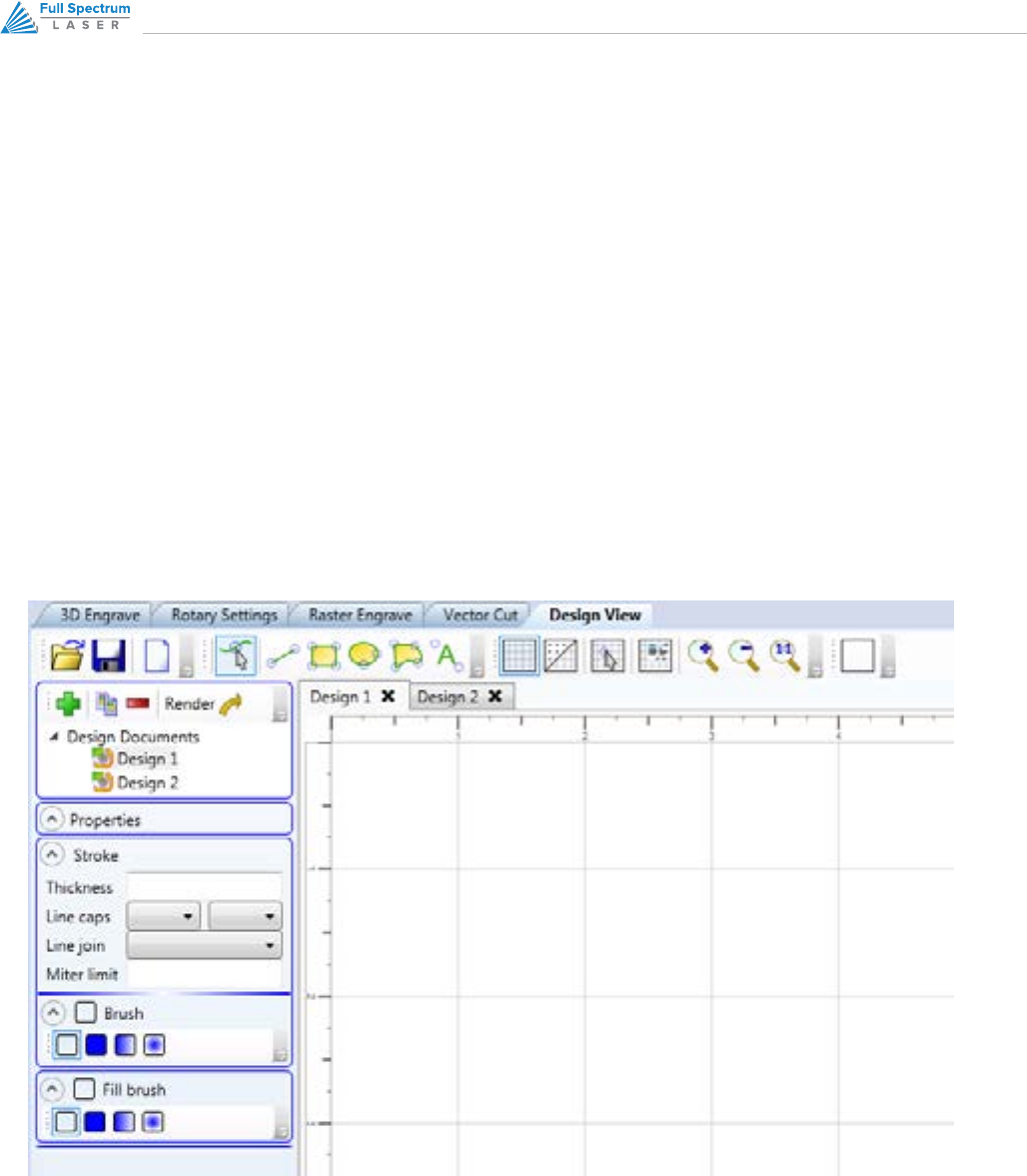
Design Tab Functionality
The Design Tab provides basic drawing tools for creating simple designs within RetinaEngrave. The tools allow you to
draw open or closed contours, complex paths, shapes and text with a variety of fill options. The Design Tab is project
based, with each project having one or more designs. Once you have a design, you select it and render it to one of
the mode tabs.
Please note:
The Design Tab is not meant to replace a dedicated drawing/design package—it exists as an internal tool for
quick tests and is released as-is. If you are having a problem with the output of the design tab, please use a
standard program such as CorelDraw to create your work and report any software issues to support@fslaser.com
LINE 1
OPEN, SAVE AND NEW PROJECT BUTTONS
These buttons allow you to load a saved project, save your current project or open a new project. Opening a
new project removes any unsaved data in the document design window
EDIT SHAPE
Select shapes or points and edit their information (color, thickness, fill, etc).
NEW LINE
Add a new point to point line. Drag the end handles to change length or use the Shape Properties box
(bottom of Shape Properties Panel) to set start and end points.
NEW RECTANGLE
Draw a rectangle. Use the handles to change proportions or the properties panel to adjust width and height
(units are inches) as well as corner radii. Use the Stroke properties to adjust corner joint type.
NEW ELLIPSE
Draw an ellipse. Use the properties panel to change the X and Y radii (units are pixels).

59RETINAENGRAVE 3D USER’S MANUAL
SHAPE PROPERTIES PANEL LEFT SIDE
NEW DRAWING, COPY DRAWING AND DELETE DRAWING
These buttons allow you to create a new drawing, delete a drawing or copy the current drawing.
DESIGN SELECTION MENU
This drop-down list allows you to select which drawing to make active via a left double-click. You can also
select the tab of the drawing you would like to work on in the design area.
DRAWING PROPERTIES
Set the total work area drawing size units in inches).
NEW PATH
Create a new spline path. Select one of the end points to bring up the Shape Properties box and add/remove
points and adjust line tangency.
NEW TEXT
Place text in the design area.
TOGGLE GRID
Changes the visibility of the drawing grid in the design area.
TOGGLE POINTS
Changes the grid format from lines to points.
TOGGLE SNAPTOGRID
Enable or disable snap functionality with drawing points.
GRID OPTIONS
This popup menu controls grid display and parameters. The Grid Width and Snap Grid Width fields can be
altered to suit your preferences; units are in inches.
ZOOM BUTTONS
Adjust the zoom level of the design area.
60
STROKE PROPERTIES
Control the stroke thickness (pixels), end point shape, joint behavior and miter behavior.
BRUSH PROPERTIES
Control the color and fill style of the brush. Allows you to create and specify gradients.
FILL PROPERTIES
Specify the properties of a closed shape
SHAPE PROPERTIES
Control the properties of the currently selected shape. Set exact size of features.
Figure 22 - Design Tab Interface

61RETINAENGRAVE 3D USER’S MANUAL
Appendix
62
APPENDIX A: PREPARING A PRINT JOB WITH CORELDRAW X5
OVERVIEW
Appendix A covers the creation of an example job using CorelDraw X5. It demonstrates several steps that are
important to properly prepare your job for printing to the laser.
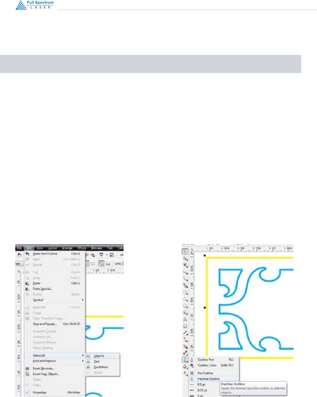
CONVERTING CURVES TO HAIRLINES
In vector mode, lines should be reduced to the minimum thickness allowable by the drawing program. In
CorelDraw X5, these are known as hairlines. If lines are not reduced to hairlines, RetinaEngrave3D may trace the
boundary of the line instead following the center of the line during vector cutting.
1. Left Click: Edit → Select All → Objects. This will select all objects.
2. Left Click: Outline Pen Tool → Hairline Outline. This will change the width of all lines to Hairline.
3. In this example object our line width is 0.5 pt
4. After applying Hairline Outline our line width is now Hairline (thinnest possible)
Figure 23 - Select All Objects, CorelDraw Figure 24 – Convert Objects to Hairline, CorelDraw
63RETINAENGRAVE 3D USER’S MANUAL
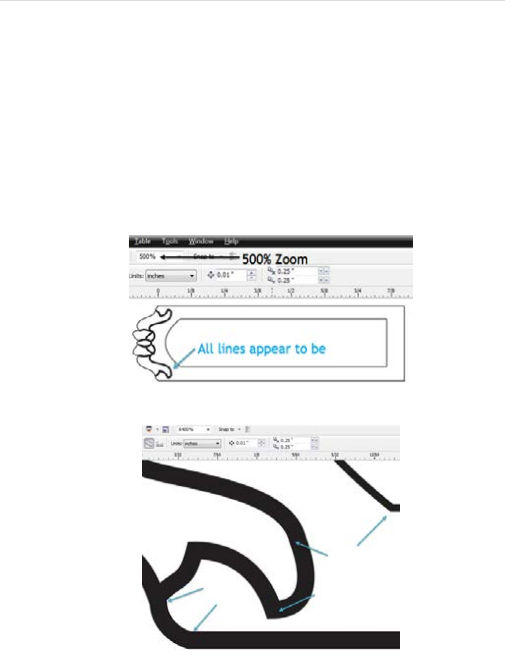
JOINING CURVES
For predictable output, vector drawing segments should be closed as much as possible. Many times vector
drawings (in particular DXF files) may have small breaks that will confuse the RetinaEngrave print driver.
CorelDraw X5 has a great command: Arrange ->Join Curves. This will join touching lines into a closed path suitable
for laser cutting. In this example our object is 1” width by 0.282” height.
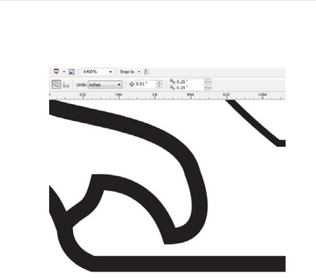
At 500% zoom the object appears to have all lines connected. However at 6400% zoom on the bottom left corner
of the same object we can see that some of the lines are merely touching and are not connected
Figure 42 - Example Drawing at 500% Zoom
Figure 25 - Example Drawing at 6400% Zoom
64
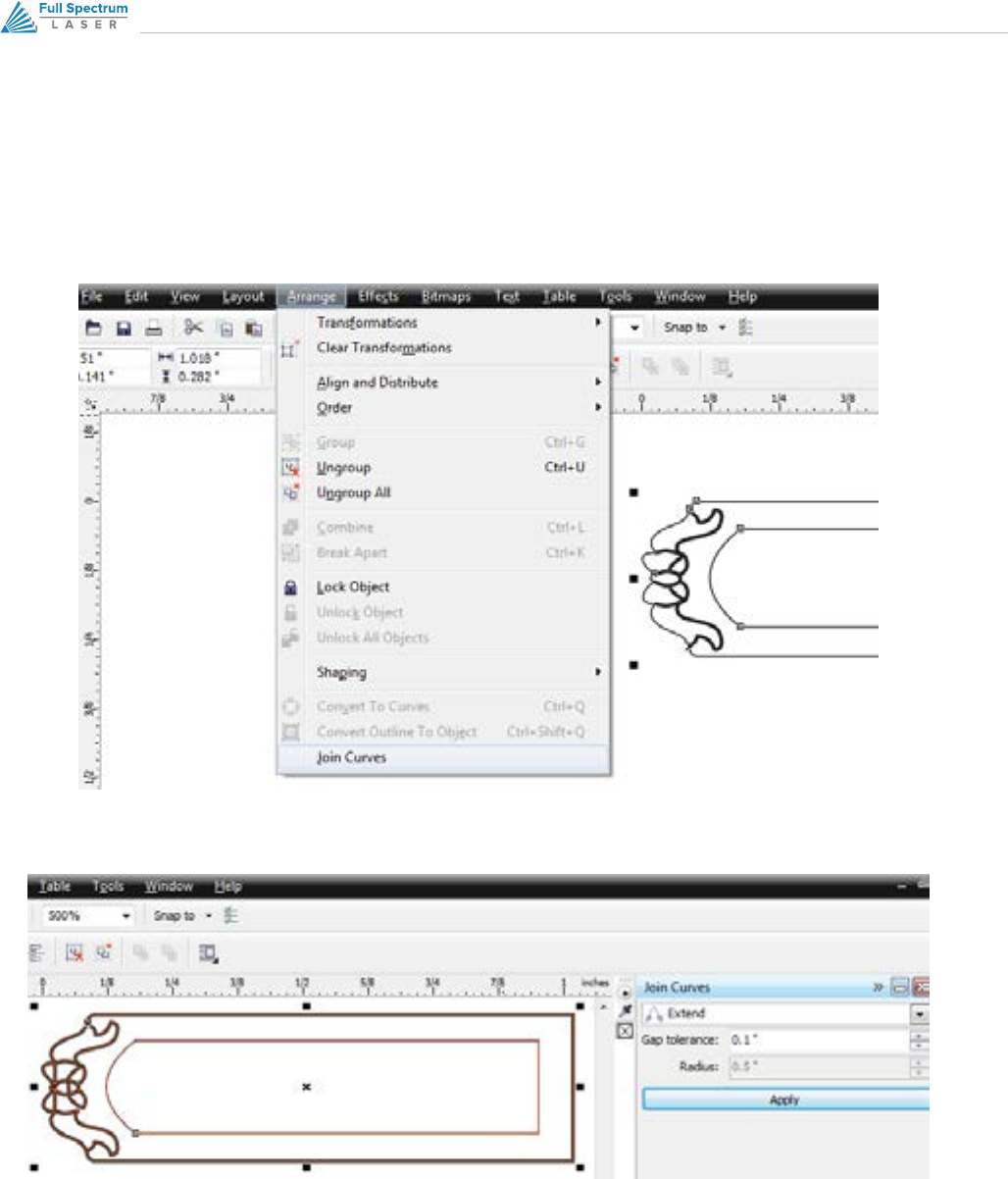
We want these lines to be continuous, so we will use the join curves command:
1. Select all objects you want to correct. Left Click on Arrange/Join Curves.
2. The Join Curves window will appear on the right side of your screen. Click Apply.
The default settings of Extend and Gap tolerance 0.1” should be sucient for most users.
65RETINAENGRAVE 3D USER’S MANUAL
Here is the same object at 6400% zoom -all lines are now connected and we have a closed path.
Figure 26 - Example Drawing at 6400% Zoom, After Processing
66
DESIGNATING COLORS TO LAYERS, CORELDRAW
Designating a color to objects/ layers you want to vector cut enables you to take advantage of RetinaEngrave3D’s
ability to specify cutting order, cut speed, laser power and number of repeats for each layer.
RetinaEngrave supports up to seven standard color layers for maximum program compatibility: Black, Blue, Red,
Magenta, Green, Cyan, and Yellow from the RGB color palette.
Always assign the outline stroke (the object border) the desired color and not the fill of the object. Always use an
empty fill when possible.
1. Open your .cdr vector format file in CorelDraw X5.
2. Make sure you have the Object Manager window open by Left Clicking: Tools, Object Manager
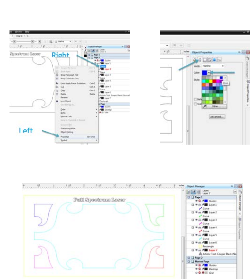
3. Right click on the object in the Object manager that you want to designate a color to.
4. Left click on “Properties” in the pop-up window
5. In the Object Properties window Left Click on the Outline Pen tab.
6. In the Outline Pen properties window Left Click on the down arrow next to “Color:” to change the outline
color of the currently selected objects to one of the seven supported colors.
In Figure 28 we have changed the outline color of one object to blue. It is possible to have more than one object
the same color. In our example image all objects that have a black outline would be considered to be on the Black
layer in RetinaEngrave and the single object with the blue outline would be considered to be on the Blue layer.
NOTE:
Repeat steps 3 through 6 as necessary to change the outline color of objects, specifying one
of the supported colors for each layer of objects up to a maximum of seven.
67RETINAENGRAVE 3D USER’S MANUAL
Figure 27 - Designating Object Color, CorelDraw
Figure 29 - Seven Object Layers, CorelDraw
Figure 28 - Colored Segment, CorelDraw