Fuji Film 01000006 Flat Panel Detector User Manual 897N120339A Z72N3191A 141015
Fuji Film Corporation Flat Panel Detector 897N120339A Z72N3191A 141015
Contents
- 1. (Short-Term Confidential) User Manual 1
- 2. (Short-Term Confidential) User Manual 2
(Short-Term Confidential) User Manual 1

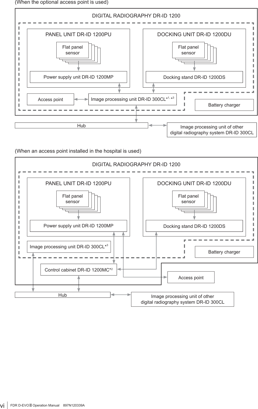

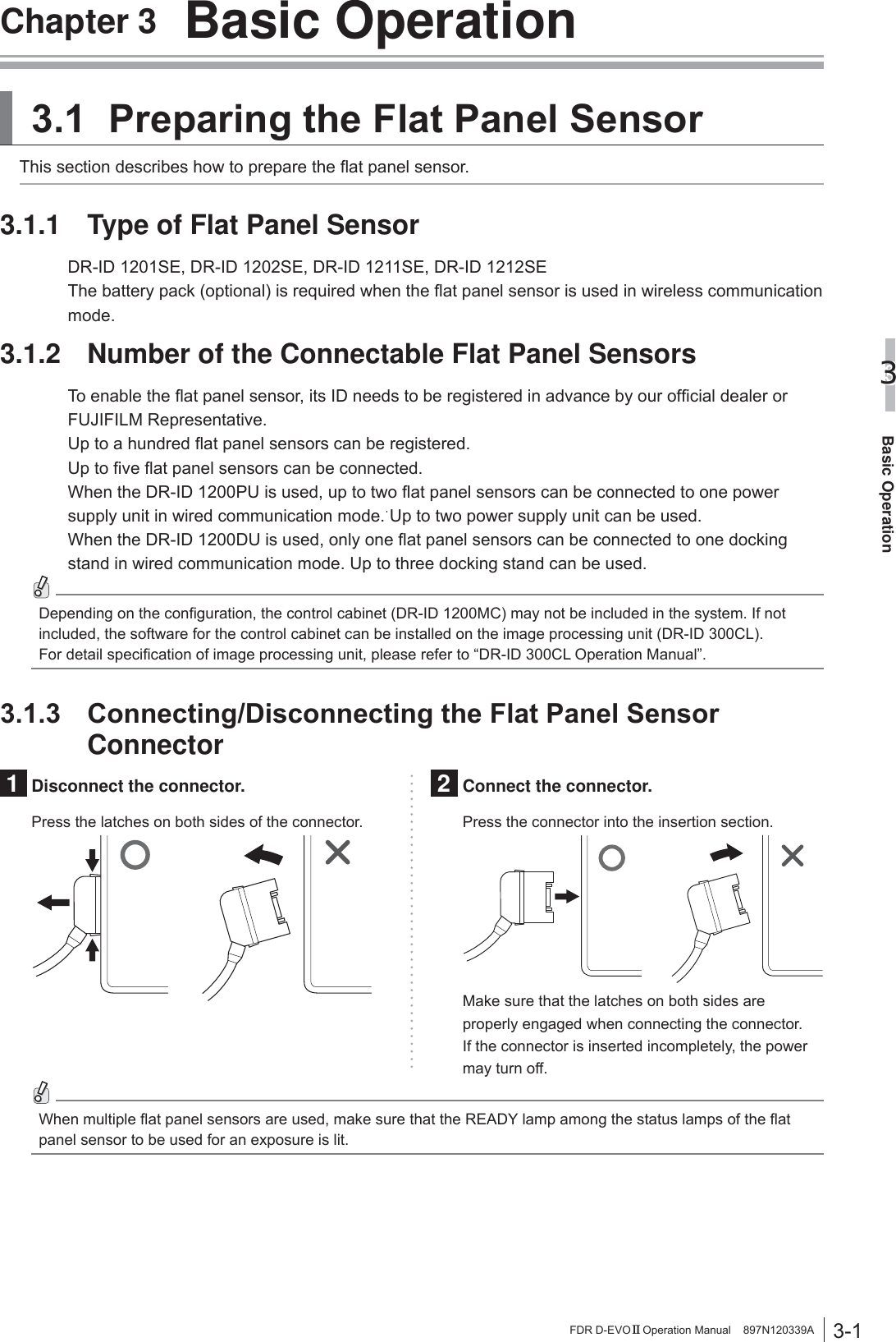
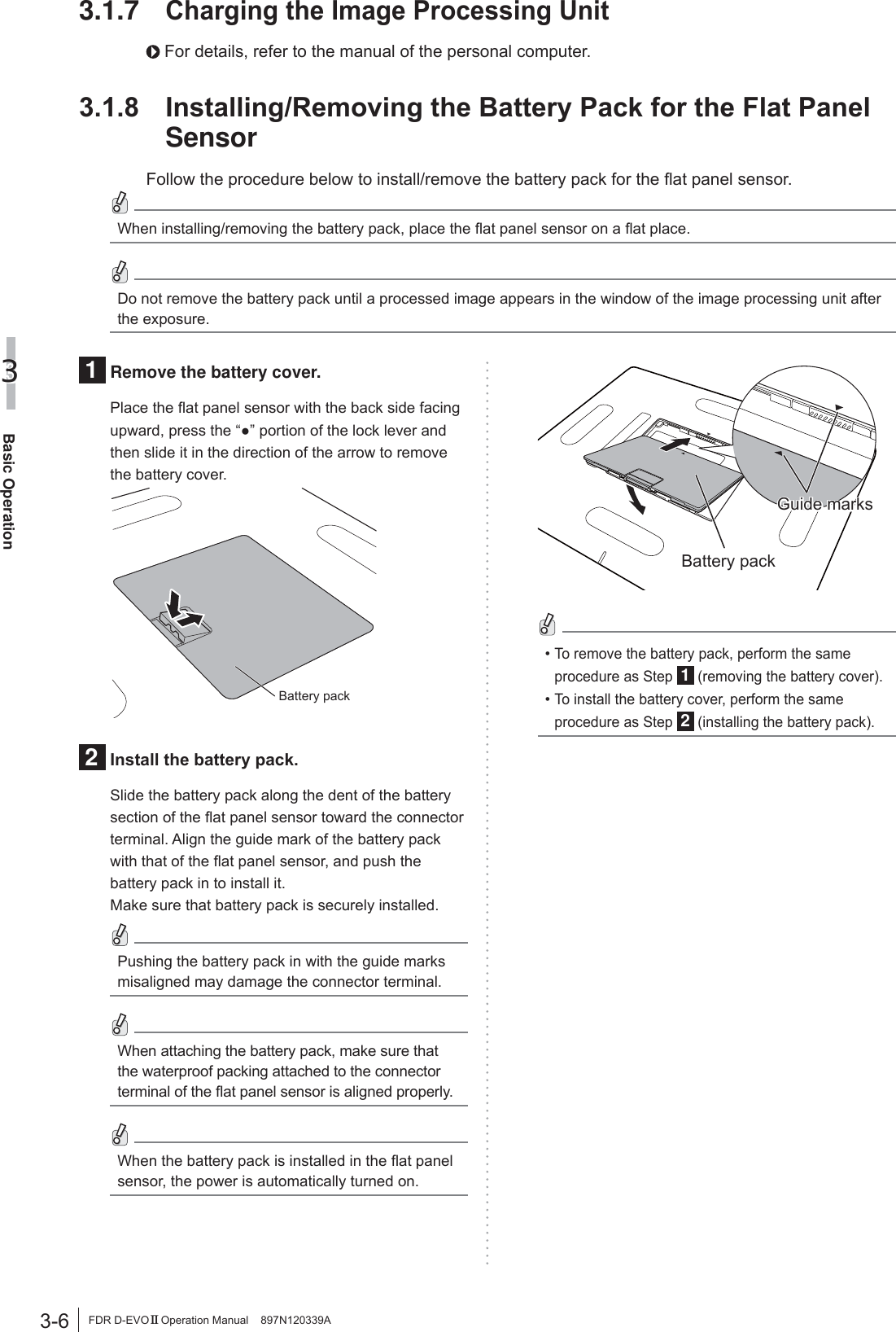
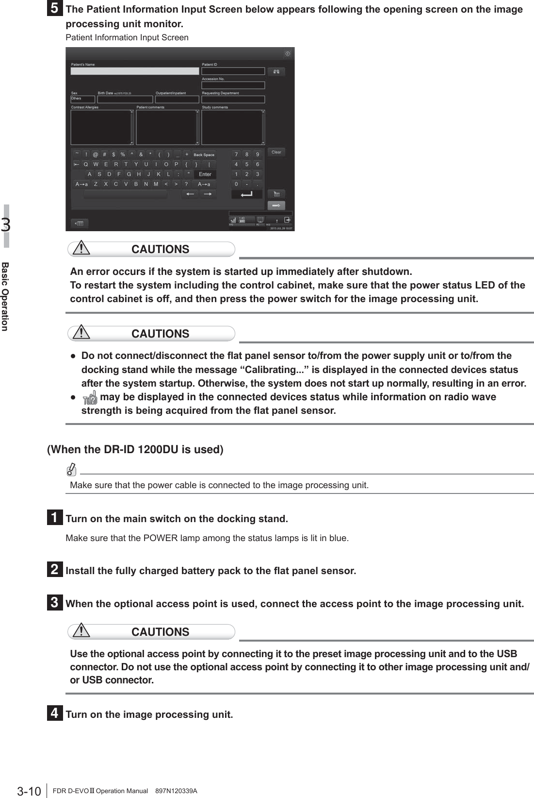
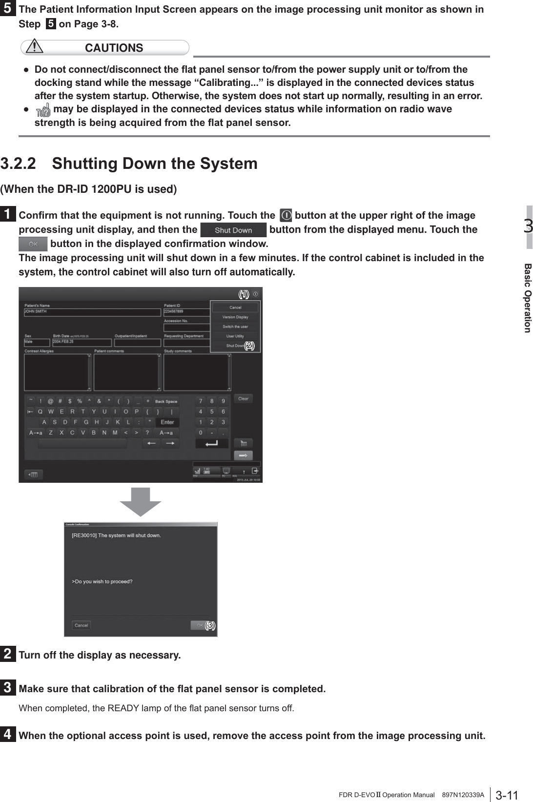
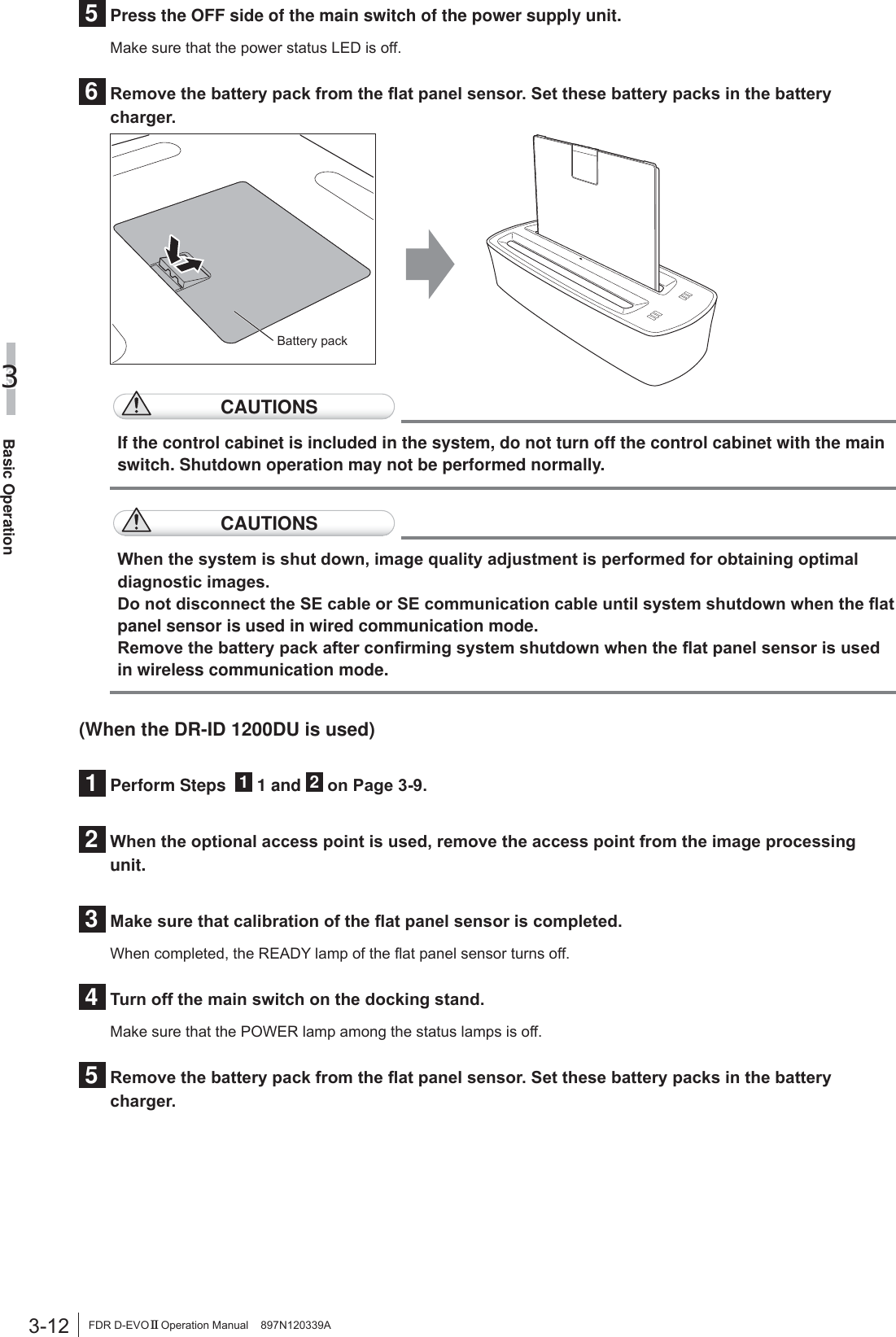
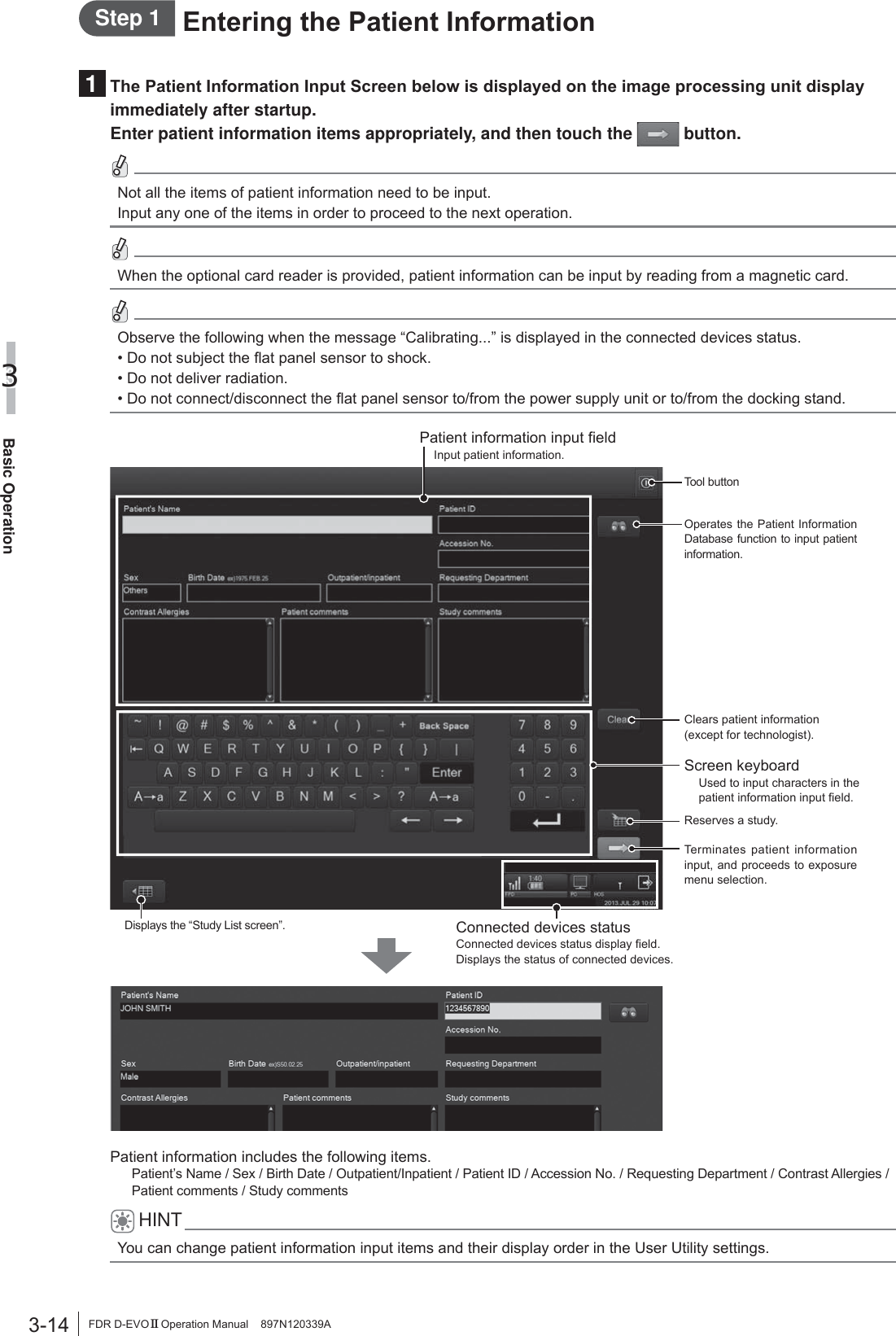
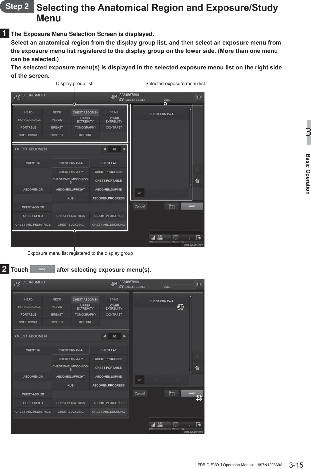
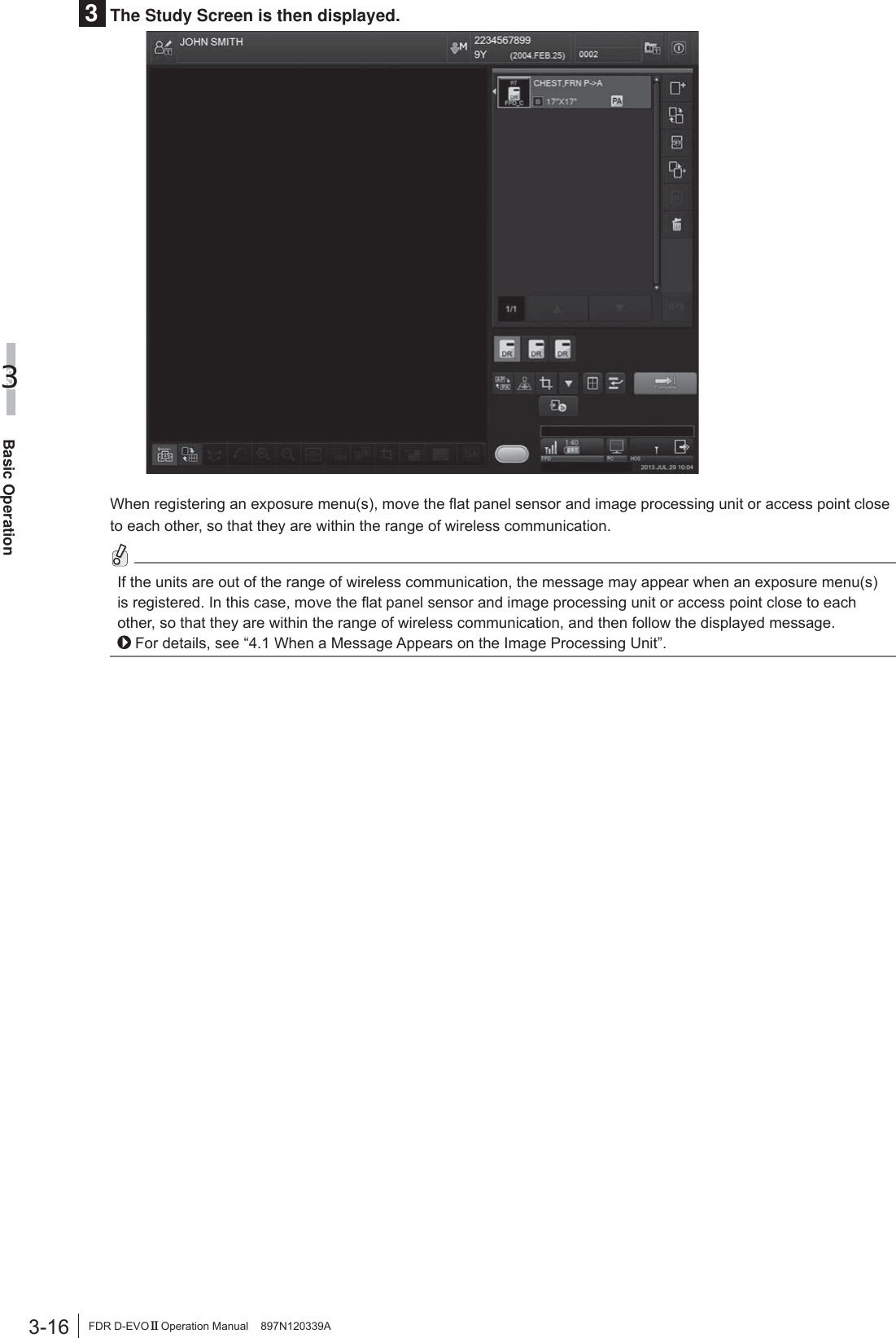
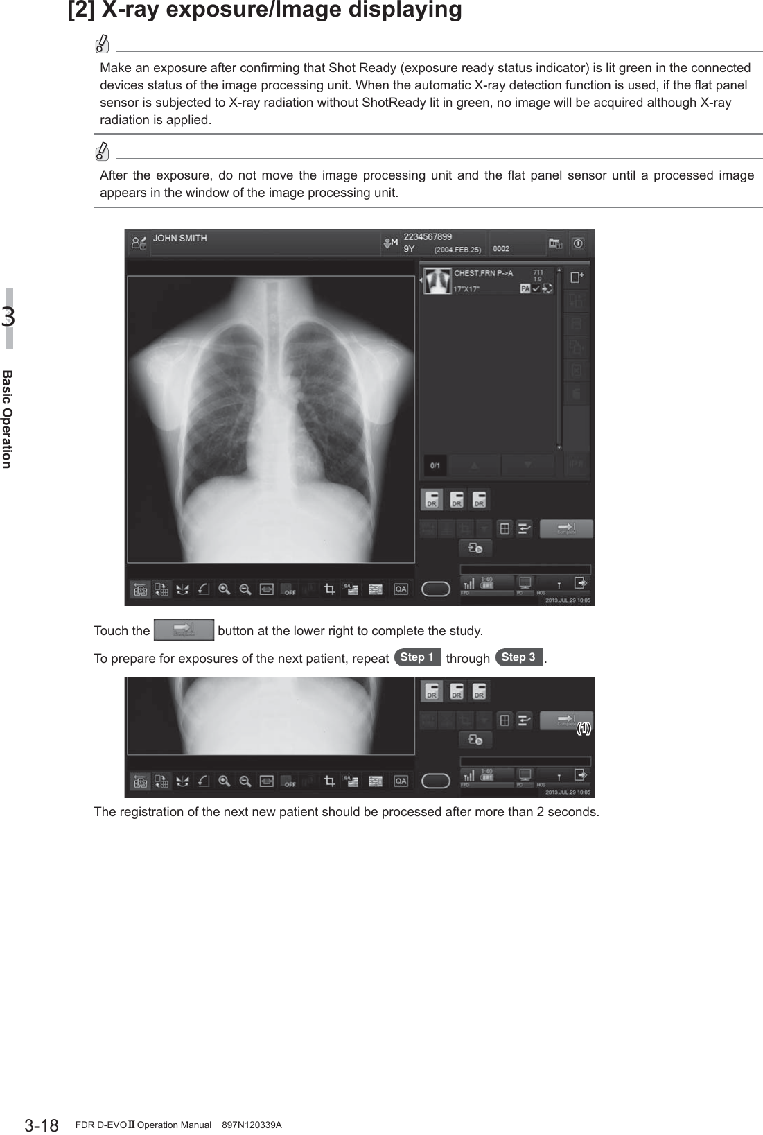
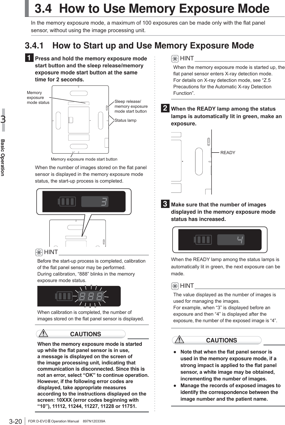
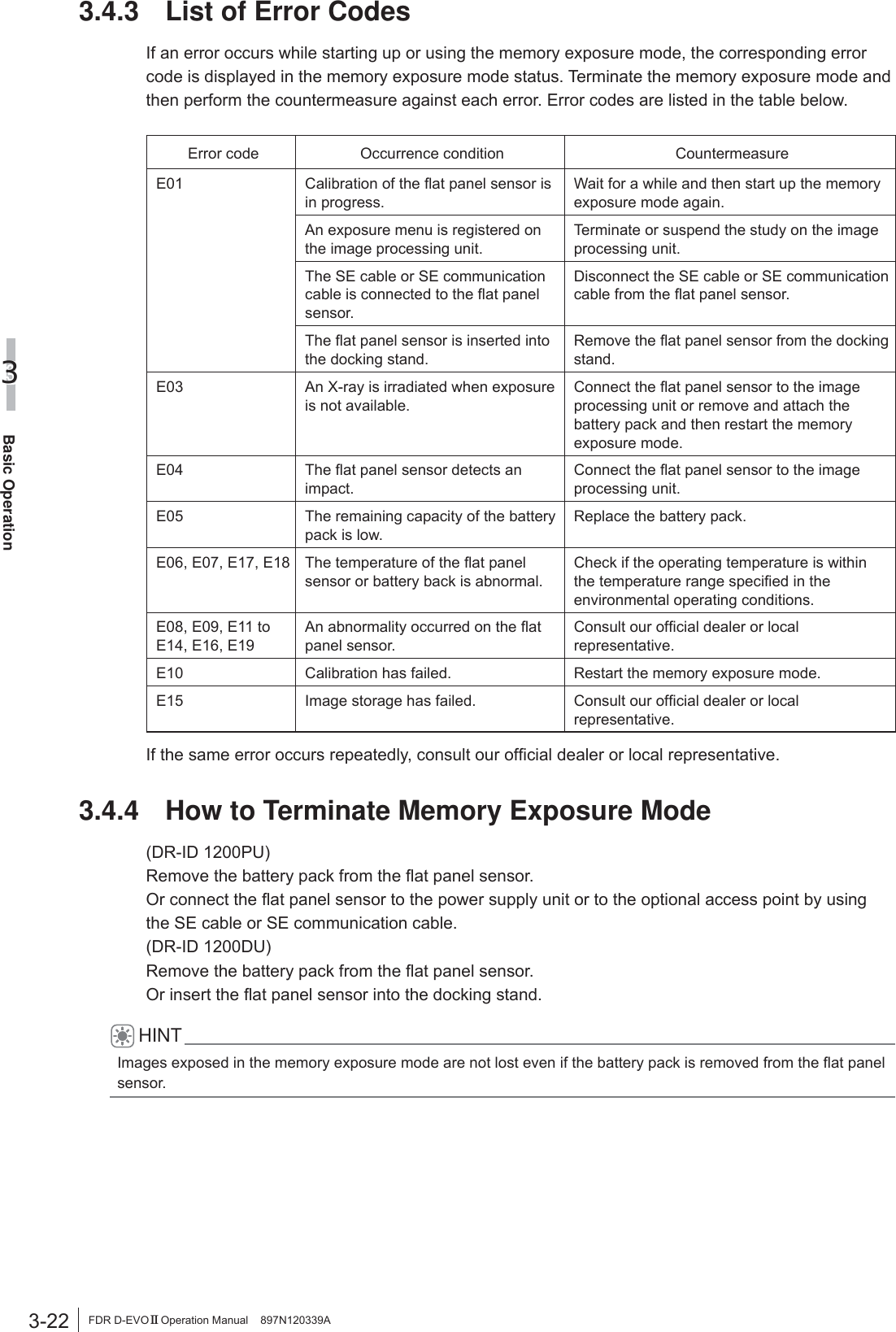
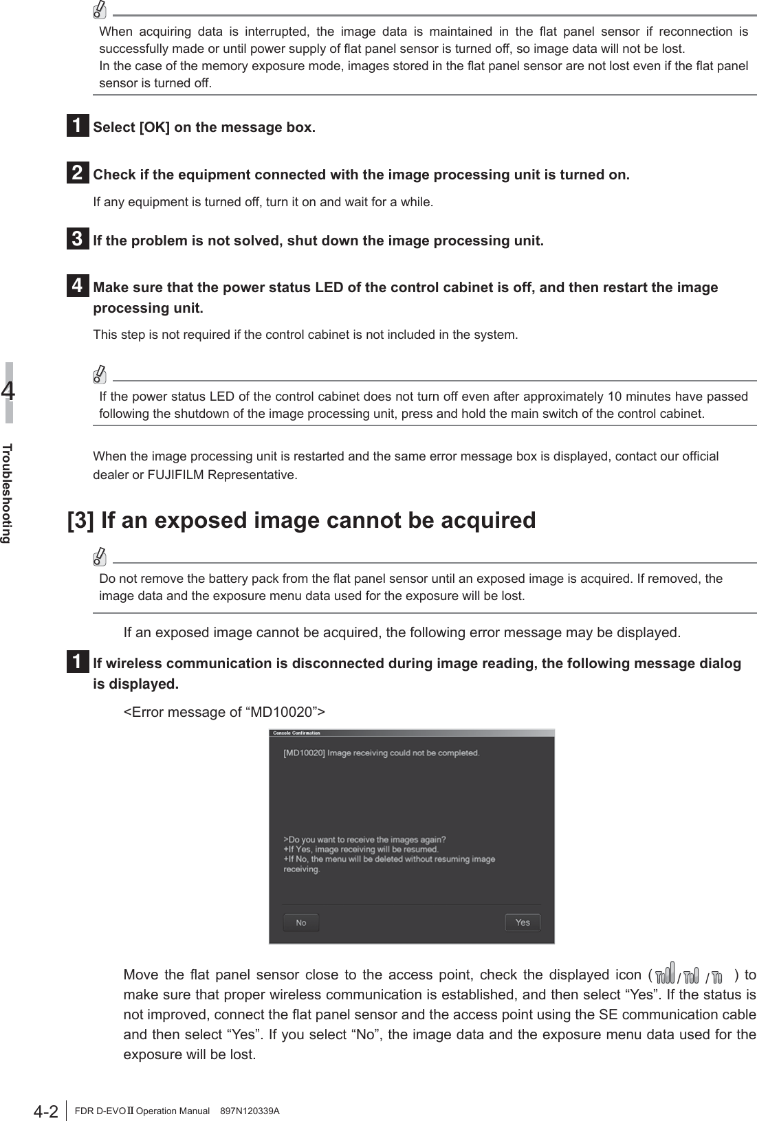
![xFDR D-EVO II Operation Manual 897N120339AHow to Read This Manual%DVLFSDJHOD\RXW3OHDVHKDYHDJRRGJUDVSRIWKHEDVLFSDJHFRQ¿JXUDWLRQRIWKLV2SHUDWLRQ0DQXDODVLOOXVWUDWHGEHORZIRU\RXWRXVHLWPRUHHI¿FLHQWO\3-9Basic Operation3FDR D-EVO II Operation Manual 897N120339A3.2 Starting Up and Shutting Down the SystemThis section explains how to start up and shut down the system. Operations are required on the power VXSSO\XQLWGRFNLQJVWDQGÀDWSDQHOVHQVRUDQGLPDJHSURFHVVLQJXQLWThe image processing unit in this section is only an example. For details on the image processing unit being used, see the Operation Manual provided with the personal computer.3.2.1 Starting Up the System(When the DR-ID 1200PU is used)Make sure that the power cable is connected to the image processing unit.1 :KHQWKHÀDWSDQHOVHQVRULVXVHGLQZLUHOHVVFRPPXQLFDWLRQPRGHLQVWDOOWKHIXOO\FKDUJHGEDWWHU\SDFNWRWKHÀDWSDQHOVHQVRU :KHQLWLVXVHGLQZLUHGFRPPXQLFDWLRQPRGHFRQQHFWWKHÀDWSDQHOVHQVRUDQGWKHSRZHUVXSSO\XQLWXVLQJWKH6(FDEOH2 3UHVVWKH21VLGHRIWKHPDLQVZLWFKRIWKHSRZHUVXSSO\XQLWMake sure that the power status LED is lit in blue.3 :KHQWKHRSWLRQDODFFHVVSRLQWLVXVHGFRQQHFWWKHDFFHVVSRLQWWRWKHLPDJHSURFHVVLQJXQLWCAUTIONS8VHWKHRSWLRQDODFFHVVSRLQWE\FRQQHFWLQJLWWRWKHSUHVHWLPDJHSURFHVVLQJXQLWDQGWRWKH86%FRQQHFWRU'RQRWXVHWKHRSWLRQDODFFHVVSRLQWE\FRQQHFWLQJLWWRRWKHULPDJHSURFHVVLQJXQLWDQGRU86%FRQQHFWRU4 3UHVVWKH21VLGHRIWKHPDLQVZLWFKRIWKHSRZHUVXSSO\XQLW 7KHLQLWLDOL]DWLRQSURFHVVVWDUWV• All cables should be connected properly.• No media should be inserted into the disk drive of image processing unit.If the control cabinet is included in the system, the control cabinet starts up automatically.CAUTIONS,IWKHSRZHUVWDWXV/('RIWKHFRQWUROFDELQHWGRHVQRWFRPHRQDIWHUWXUQLQJRQWKHLPDJHSURFHVVLQJXQLWWXUQRQWKHFRQWUROFDELQHW3DJHQXPEHUDisplayed in conjunction with the chapter number.Section titleShows the title of an operation procedure described in the section.LeadDescribes information we wish you to know in advance of your operating the system or information that may help you to operate it. Operation procedureDescribes an operation procedure according to sequential numbers.IndexA caption that facilitates you to open a desired [Chapter] quickly.](https://usermanual.wiki/Fuji-Film/01000006.Short-Term-Confidential-User-Manual-1/User-Guide-2473601-Page-10.png)
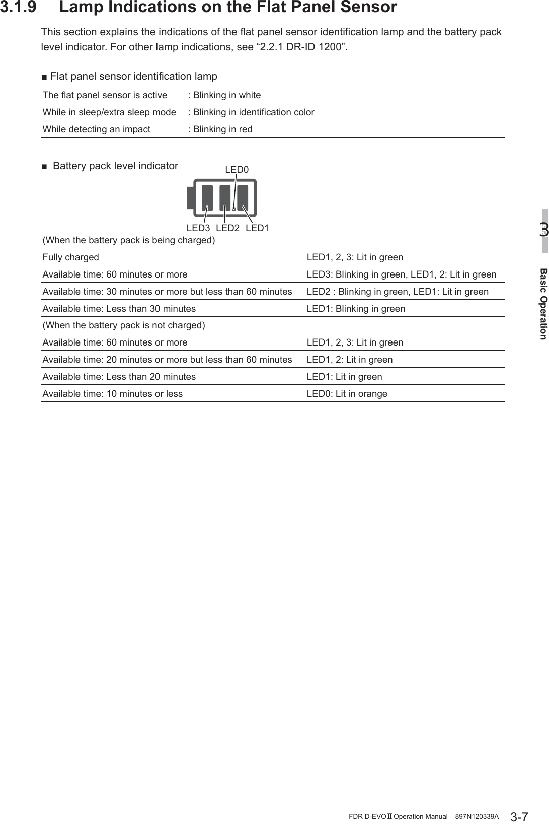
![xiiiFDR D-EVO II Operation Manual 897N120339AChapter 3 Basic Operation3.1 Preparing the Flat Panel Sensor .............................................................................3-13.1.1 Type of Flat Panel Sensor .......................................................................................3-13.1.2 Number of the Connectable Flat Panel Sensors .....................................................3-13.1.3 Connecting/Disconnecting the Flat Panel Sensor Connector ..................................3-13.1.4 Inserting/Removing the Flat Panel Sensor into/ from the Radiographic Examination Stand ..............................................................3-23.1.5 Changing the Direction of the Flat Panel Sensor Connector ...................................3-43.1.6 Charging the Battery Pack for the Flat Panel Sensor ..............................................3-53.1.7 Charging the Image Processing Unit ..............................................................................3-63.1.8 Installing/Removing the Battery Pack for the Flat Panel Sensor .............................3-63.1.10 Attaching the Flat Panel Sensor to the Docking Stand ............................................3-83.2 Starting Up and Shutting Down the System ...............................................................................3-93.2.1 Starting Up the System ............................................................................................3-93.2.2 Shutting Down the System .................................................................................... 3-113.3 Routine Operations ....................................................................................................3-13Step 1 Entering the Patient Information .............................................................................3-14Step 2 Selecting the Anatomical Region and Exposure/Study Menu .................................3-15Step 3 X-ray Exposure .......................................................................................................3-17 [1] Positioning the patient ......................................................................................3-17 [2] X-ray exposure/Image displaying .....................................................................3-18 [3] Sleep mode .......................................................................................................3-19 [4] Extended Image Readout .................................................................................3-193.4 How to Use Memory Exposure Mode ........................................................................3-203.4.1 How to Start up and Use Memory Exposure Mode ...............................................3-203.4.2 How to Load Images ..............................................................................................3-213.4.3 List of Error Codes .................................................................................................3-223.4.4 How to Terminate Memory Exposure Mode ...........................................................3-22&KDSWHU7URXEOHVKRRWLQJ4.1 When a Message Appears on the Image Processing Unit .................................................... 4-1[1] If a warning dialog box appears ......................................................................................4-1[2] If the message dialogue box MD11001 appears ..............................................................4-1[3] If an exposed image cannot be acquired .........................................................................4-2[4] If the dialog box containing the error message numbered 13048 appears ......................4-3[5] If “Unusable due to error.” appears on the image processing unit ................................................4-3[6] If any other message dialogue box appears ....................................................................4-44.2 How to Cope with an Error... ...................................................................................4-5[1] When the image processing unit hangs up… ..................................................................4-5[2] When the image processing unit is turned off due to an electrical outage .......................4-5[3] If a hard disk of the image processing unit is damaged ...................................................4-6[4] If a white image is displayed after an exposure ...............................................................4-6[5] Precautions for operation when the device status is “Initializing” or “Changing FPD” in the image processing unit’s “Output Device Status window” ............4-6>@,IWKHÀDWSDQHOVHQVRUFDQQRWEHXVHGLQZLUHOHVVFRPPXQLFDWLRQPRGH ......................4-6[7] If an error occurs on an output destination device ...........................................................4-7Chapter 5 Daily Inspection and Maintenance5.1 Daily User Inspection and Maintenance .................................................................... 5-15.1.1 Daily Inspection (DR-ID 1200) .................................................................................5-15.1.2 Periodical Inspection ................................................................................................5-2](https://usermanual.wiki/Fuji-Film/01000006.Short-Term-Confidential-User-Manual-1/User-Guide-2473601-Page-13.png)
![1-5For Safe Operation1FDR D-EVO II Operation Manual 897N120339A:DUQLQJVIRU$EQRUPDOLWLHVWARNING,IDQ\RIWKHIROORZLQJRFFXUVLPPHGLDWHO\WXUQRIIWKHSRZHURIHDFKXQLWXQSOXJWKHSRZHUFDEOHIURPWKHRXWOHWDQGWKHQFRQWDFWRXURI¿FLDOGHDOHURU)8-,),/05HSUHVHQWDWLYHƔ :KHQVPRNHVWUDQJHRGRURUDEQRUPDOVRXQGLVSUHVHQWƔ :KHQDIRUHLJQREMHFWVXFKDVDPHWDOREMHFWRUOLTXLGHQWHUVWKHSURGXFWƔ :KHQWKHHTXLSPHQWLVGURSSHGRUKLWDQGLVGDPDJHGAvertissements relatifs aux anomalies AVERTISSEMENT6LO¶XQHGHVFRQGLWLRQVUpSHUWRULpHVFLDSUqVVHSURGXLWPHWWH]LPPpGLDWHPHQWFKDTXHXQLWphors tension, débranchez le cordon d’alimentation de la prise secteur, puis contactez notre UHYHQGHXUDJUppRXQRWUHUHSUpVHQWDQW)8-,),/0Ɣ (QFDVGHSUpVHQFHGHIXPpHG¶XQHRGHXUpWUDQJHRXG¶XQEUXLWDQRUPDOƔ (QFDVGHSpQpWUDWLRQG¶XQFRUSVpWUDQJHUFRPPHXQREMHWPpWDOOLTXHRXG¶XQOLTXLGHGDQVle produit. Ɣ (QFDVG¶HQGRPPDJHPHQWGHO¶pTXLSHPHQWVXLWHjXQHFKXWHRXjXQLPSDFWInstallation PrecautionsCAUTIONS'RQRWLQVWDOOWKHV\VWHPLQDORFDWLRQZLWKWKHIROORZLQJFRQGLWLRQVƔ :KHUHWKHWHPSHUDWXUHFKDQJHVVKDUSO\Ɣ &ORVHWRKHDWVRXUFHVVXFKDVDKHDWHUƔ :KHUHWKHV\VWHPPD\EHH[SRVHGWRZDWHUGXHWRZDWHUOHDNDJHRULQJUHVVƔ :KHUHFRUURVLYHJDVPD\EHJHQHUDWHGƔ :KHUHWKHUHLVH[FHVVLYHGXVWƔ :KHUHWKHV\VWHPLVVXEMHFWWRIUHTXHQWRUH[FHVVLYHYLEUDWLRQVKRFNƔ :KHUHWKHV\VWHPLVH[SRVHGWRGLUHFWVXQOLJKWƔ :KHUHWKHUHLVQRYHQWLODWRUCAUTIONS8VHWKHHTXLSPHQWRQDÀDWSODFH,IWKHHTXLSPHQWIDOOVLWPD\FDXVHGDPDJHWRWKHHTXLSPHQWor personal injury.CAUTIONS:KHQ\RXPRYHWKHHTXLSPHQWSODFHLWLQWKHFDVVHWWHVWRUDJHER[RIDPRELOH;UD\XQLWRUKROGLWE\KDQGWRSUHYHQWLWIURPIDOOLQJ,IWKHFDUWLVXVHGWRPRYHWKHHTXLSPHQWSODFHLWKRUL]RQWDOO\CAUTIONS)RUYHWHULQDU\RUPRELOHDSSOLFDWLRQVSOHDVHFRQWDFWRXURI¿FLDOGHDOHURU)8-,),/0Representative.CAUTIONS:KHQWKHGHYLFHVDUHXVHGRXWGRRUVLQZLUHOHVVFRPPXQLFDWLRQPRGHFRQWDFWRXURI¿FLDOdealer or FUJIFILM Representative.](https://usermanual.wiki/Fuji-Film/01000006.Short-Term-Confidential-User-Manual-1/User-Guide-2473601-Page-19.png)
![1-6For Safe Operation1FDR D-EVO II Operation Manual 897N120339ACAUTIONS/ATTENTIONDo not place any object in a place where removal of the power cable is prevented.1HSODFH]DXFXQREMHWjXQHPSODFHPHQWJrQDQWOHGpEUDQFKHPHQWGXFkEOHG¶DOLPHQWDWLRQCAUTIONS7RHQVXUHRSWLPDOLPDJHTXDOLW\LWLVUHFRPPHQGHGWKDW\RXGRQRWXVHWKHÀDWSDQHOVHQVRUQHDUGHYLFHVPRWRUWUDQVIRUPHUVZLWFKLQJVXSSO\HWFWKDWJHQHUDWHHOHFWURPDJQHWLFQRLVHCAUTIONS7RHQVXUHRSWLPDOLPDJHTXDOLW\LWLVUHFRPPHQGHGWKDW\RXGRQRWSODFHWKHFDEOHVSRZHUFDEOHFRPPXQLFDWLRQFDEOHHWFRIWKHHTXLSPHQWQHDUGHYLFHVPRWRUWUDQVIRUPHUVZLWFKLQJVXSSO\HWFWKDWJHQHUDWHHOHFWURPDJQHWLFQRLVHDQGWKHLUFDEOHVCAUTIONSDo not install the power supply unit in a place where it may be contacted inadvertently. In DGGLWLRQWDNHFDUHQRWWRPDNHFRQWDFWZLWKWKHSRZHUVXSSO\XQLWH[FHSWZKHQRSHUDWLQJWKHmain switch. If the fan inside the power supply unit malfunctions, the power supply unit may EHFRPHKRWFDXVLQJLQMXU\Connection InstructionsWARNING0DNHVXUHWKDWWKHGHYLFHVWREHFRQQHFWHGWRWKHHTXLSPHQWDUHDXWKRUL]HGIRUFRQQHFWLRQWARNING&RQQHFWWKHSDQHOXQLW'5,'38DQGWKHGRFNLQJXQLW'5,''8RQO\WRWKHDFFHVVSRLQWLPDJHSURFHVVLQJXQLWRUWKHFRQWUROFDELQHW3UHFDXWLRQVRQ([WHUQDO1HWZRUN&RQQHFWLRQCAUTIONS:KHQDVHWWLQJRIWKHQHWZRUNWRZKLFKWKHHTXLSPHQWLVFRQQHFWHGKDVEHHQFKDQJHGFKHFNWKDWWKHFKDQJHGRHVQRWDIIHFWWKHV\VWHPRSHUDWLRQDQGWDNHPHDVXUHVLIQHFHVVDU\7KHVHWWLQJFKDQJHPD\LQFOXGHWKHIROORZLQJƔ &KDQJHRIFRQQHFWLRQGHVWLQDWLRQƔ $GGLWLRQRIGHYLFHVƔ 5HPRYDORIGHYLFHVƔ 8SGDWHRIGHYLFHVƔ 8SJUDGHRIGHYLFHV](https://usermanual.wiki/Fuji-Film/01000006.Short-Term-Confidential-User-Manual-1/User-Guide-2473601-Page-20.png)
![1-7For Safe Operation1FDR D-EVO II Operation Manual 897N120339A:DUQLQJVDQG&DXWLRQVRQ1HWZRUNWARNING0DNHVXUHWRXVHWKHRSWLRQDOSDUWVDFFHVVRULHVDQGQHWZRUNVUHFRPPHQGHGE\XV)DLOXUHWRXVHWKHRSWLRQDOSDUWVDFFHVVRULHVDQGQHWZRUNVUHFRPPHQGHGE\XVPD\UHVXOWLQGDPDJHWRWKHHTXLSPHQWDQGRUHOHFWULFVKRFNDQGLQMXU\CAUTIONS&RQQHFWWRWKH(WKHUQHW1HWZRUNRI%$6(7;RU%$6(7SUHVFULEHGLQWKH,(((VWDQGDUG'RQRWFRQQHFWWHOHSKRQHOLQHVWR/$1FRQQHFWRU2QO\873W\SHVWUDLJKW/$1FDEOHVRISDLU&DWHJRU\FDEOH&$7(RUKLJKHUDUHDSSURSULDWHIRUFRQQHFWLRQWRWKLVFRQQHFWRUCAUTIONS$IWHUFRQQHFWLQJWKLVV\VWHPWRWKHQHWZRUNZLWKRWKHUV\VWHPVFRQ¿UPWKDWWKHRWKHUV\VWHPVDUHQRWDIIHFWHG,IWKH\DUHDIIHFWHGWDNHFRXQWHUPHDVXUHVVXFKDVQHWZRUNVHSDUDWLRQSystem Isolation InstructionsWARNINGTo ensure complete system isolation, never install any unauthorized accessories or other such items.:KHQLWLVQHFHVVDU\WRLQVWDOODXWKRUL]HGDFFHVVRULHVRURSWLRQDOLWHPVFRQWDFWRXURI¿FLDOdealer or FUJIFILM Representative.WARNING.HHSHTXLSPHQWRWKHUWKDQWKRVHXVHGIRUSDWLHQWVRXWRIWKHLUUHDFKWRHQVXUHDSSURSULDWHsystem isolation.WARNING,QQRUPDOXVHKDYHDSDWLHQWWDNHDSURSHUSRVLWLRQLQJIRUH[SRVXUH7KHRSHUDWRUVKRXOGoperate the system in a place where safety from radiation is ensured. The operator should DOVRPDNHVXUHEHIRUHH[SRVXUHWKDWQRRQHEXWWKHSDWLHQWLVLQWKHH[SRVXUHDUHDDQGWKHRSHUDWLQJDUHDRIWKHV\VWHPSoftware PrecautionsCAUTIONSDo not install additional software to the system. Do not uninstall any of the software preinstalled in the system. The system is preinstalled with the appropriate software. If other software is installed or if the H[LVWLQJVRIWZDUHLVXQLQVWDOOHGYDULRXVRSHUDWLRQDOHUURUVPD\UHVXOW](https://usermanual.wiki/Fuji-Film/01000006.Short-Term-Confidential-User-Manual-1/User-Guide-2473601-Page-21.png)
![1-8For Safe Operation1FDR D-EVO II Operation Manual 897N120339ADisinfection InstructionsWARNING&RQ¿UPWKDWWKHUHVSLUDWRU\GHQVLW\RIGLVLQIHFWDQWLQFOXGLQJVROYHQWLVXQGHUOHJDOUHJXODWLRQ&HUWDLQGLVLQIHFWDQWVPD\GDPDJHKHDOWK:KHQXVLQJDGLVLQIHFWDQWIROORZLQVWUXFWLRQVsupplied by the manufacturers.WARNING'RQRWXVHWKHIROORZLQJGLVLQIHFWDQWVRUVWHULOL]HUVDWWKHWLPHRIGLVLQIHFWLRQ4XDOLW\SHUIRUPDQFHDQGVDIHW\RIWKHHTXLSPHQWFDQQRWEHDVVXUHGƔ &KORULFGLVLQIHFWDQWZKLFKLVVWURQJO\FRUURVLYHWRPHWDOVDQGUXEEHUSDUWVƔ 'LVLQIHFWDQWZKRVHXVHVRQPHWDOVSODVWLFVDQGFRDWLQJDUHIRUELGGHQDFFRUGLQJWRWKHinstructions supplied with the disinfectant.Ɣ )RUPDOLQJDVDQGGLVLQIHFWDQWVSUD\VWKDWPD\JHWLQVLGHWKHHTXLSPHQWƔ 8OWUDYLROHWVWHULOL]HUVDisinfectant ethanol is recommended for disinfection. Carefully read the instructions and cautions supplied with the disinfectant before use.For details on the disinfectant, contact a FUJIFILM dealer or the service representatives at the DJHQF\IURPZKLFK\RXSXUFKDVHGWKHGLVLQIHFWDQWCAUTIONS,IÀDWSDQHOVHQVRULVQRWGLVLQIHFWHGLWPD\OHDGVHFRQGDU\LQIHFWLRQBe sure to disinfect with ethanol after use.CAUTIONS&OHDQWKHVHQVRUXQLWRIWKHÀDWSDQHOVHQVRUZLWKHWKDQROIRUGLVLQIHFWLRQHWFIRUHDFKSDWLHQWto prevent infection.3UHFDXWLRQVIRU&KDUJLQJWKH%DWWHU\3DFNCAUTIONS2EVHUYHWKHIROORZLQJSUHFDXWLRQVZKHQFKDUJLQJWKHEDWWHU\SDFNRSWLRQDOXVLQJWKHEDWWHU\FKDUJHURSWLRQDOƔ 'RQRWXVHWKHEDWWHU\SDFN<RUEDWWHU\FKDUJHULQFRPELQDWLRQZLWKDQ\EDWWHU\SDFNRUEDWWHU\FKDUJHULQFOXGLQJWKHSRZHUFDEOHRWKHUWKDQWKRVHUHFRPPHQGHGE\FUJIFILM Corporation.Ɣ 'RQRWGLVDVVHPEOHRUFRQYHUWWKHEDWWHU\SDFNRUEDWWHU\FKDUJHUƔ ,IWKHEDWWHU\SDFNRUEDWWHU\FKDUJHUEHFRPHVIDXOW\FRQVXOWRXURI¿FLDOGHDOHURU)8-,),/0Representative.Ɣ 'RQRWFRYHUWKHKROHVLQWKHEDWWHU\FKDUJHUZLWKIRUHLJQPDWWHUƔ $YRLGWKHDFFXPXODWLRQRIGXVWRQWKHEDWWHU\FKDUJHUƔ ,QVHUWWKHEDWWHU\SDFNLQWRWKHEDWWHU\FKDUJHUVHFXUHO\Ɣ ,IWKHLQVHUWLRQGLUHFWLRQRUSRVLWLRQRIWKHEDWWHU\SDFNLVLQFRUUHFWWKHEDWWHU\SDFNLVQRWFKDUJHGSURSHUO\Ɣ :KHQLQVHUWLQJWKHEDWWHU\SDFNSUHYHQWIRUHLJQPDWWHUIURPJHWWLQJLQWRWKHEDWWHU\FKDUJHUƔ :KLOHFKDUJLQJWKHEDWWHU\SDFNGRQRWDOORZWKHEDWWHU\SDFNRUEDWWHU\FKDUJHUJHWZHWRUdusty.Ɣ 'RQRWVWHSRQWKH$&DGDSWHURIWKHEDWWHU\FKDUJHU$OVREHFDUHIXOQRWWRWULSRYHUWKHpower cable.Ɣ 'RQRWVXEMHFWWKHEDWWHU\SDFNDQGEDWWHU\FKDUJHUWRVHYHUHVKRFNE\GURSSLQJWKHPHWFƔ 'RQRWSODFHWKHEDWWHU\FKDUJHUZLWKLQWKHUHDFKRISDWLHQWV](https://usermanual.wiki/Fuji-Film/01000006.Short-Term-Confidential-User-Manual-1/User-Guide-2473601-Page-22.png)
![1-10For Safe Operation1FDR D-EVO II Operation Manual 897N120339AƔ 'RQRWLPPHUVHWKHEDWWHU\SDFNLQZDWHURUVHDZDWHUDQGGRQRWDOORZLWWREHFRPHZHW,IWKHEXLOWLQSURWHFWLRQPHFKDQLVPVDUHGDPDJHGWKHEDWWHU\SDFNPD\RYHUKHDWHPLWVPRNHH[SORGHRULJQLWHƔ 'RQRWSLHUFHWKHEDWWHU\SDFNZLWKDQDLOKLWLWZLWKDKDPPHURUVWHSRQLW2WKHUZLVHWKHEDWWHU\SDFNPD\EHGDPDJHGRUGHIRUPHGDQGVKRUWFLUFXLWFDXVLQJLWWRRYHUKHDWHPLWVPRNHH[SORGHRULJQLWHƔ 'RQRWVXEMHFWWKHEDWWHU\SDFNWRVWURQJLPSDFWRUWKURZLW,IWKHEXLOWLQSURWHFWLRQPHFKDQLVPVDUHGDPDJHGWKHEDWWHU\SDFNPD\EHFKDUJHGZLWKH[WUHPHO\KLJKFXUUHQWDQGYROWDJHDQGDEQRUPDOFKHPLFDOUHDFWLRQVPD\RFFXULQVLGHWKHEDWWHU\SDFNFDXVLQJLWWRRYHUKHDWHPLWVPRNHH[SORGHRULJQLWHƔ 'RQRWXVHDQDSSDUHQWO\GDPDJHGRUGHIRUPHGEDWWHU\SDFN2WKHUZLVHWKHEDWWHU\SDFNPD\RYHUKHDWHPLWVPRNHH[SORGHRULJQLWHƔ 'RQRWVROGHUWKHEDWWHU\SDFNGLUHFWO\2WKHUZLVHLWVLQVXODWRUPD\PHOWRULWVJDVUHOHDVHYHQWRUVDIHW\PHFKDQLVPVPD\EHGDPDJHGFDXVLQJWKHEDWWHU\SDFNWRRYHUKHDWHPLWVPRNHH[SORGHRULJQLWHƔ 'RQRWUHYHUVHWKHSRVLWLYHDQGQHJDWLYHWHUPLQDOV2WKHUZLVHWKHEDWWHU\SDFNPD\EHUHYHUVHFKDUJHGGXULQJFKDUJLQJ$VDUHVXOWDEQRUPDOFKHPLFDOUHDFWLRQVPD\RFFXULQVLGHWKHEDWWHU\SDFNRUH[WUHPHO\KLJKFXUUHQWPD\ÀRZGXULQJGLVFKDUJLQJFDXVLQJLWWRRYHUKHDWHPLWVPRNHH[SORGHRULJQLWHƔ 7KHEDWWHU\SDFNKDVDSUHGHWHUPLQHGSRODULW\,I\RXFDQQRWFRQQHFWWKHEDWWHU\SDFNWRWKHEDWWHU\FKDUJHURURWKHUHTXLSPHQWGRQRWFRQQHFWWKHEDWWHU\SDFNIRUFHIXOO\0DNHVXUHWKDWWKHWHUPLQDOVDUHFRUUHFWO\RULHQWHG,IWKHEDWWHU\SDFNLVFRQQHFWHGLQUHYHUVHLWZLOOEHUHYHUVHFKDUJHGDQGDEQRUPDOFKHPLFDOUHDFWLRQVPD\RFFXULQVLGHWKHEDWWHU\SDFNFDXVLQJLWWRRYHUKHDWHPLWVPRNHH[SORGHRULJQLWHƔ 'RQRWFRQQHFWWKHEDWWHU\SDFNWRDQHOHFWULFDORXWOHWRUFLJDUHWWHOLJKWHUVRFNHWLQDFDU2YHUFXUUHQWPD\ÀRZWRWKHEDWWHU\SDFNGXHWRKLJKYROWDJHDSSOLHGFDXVLQJWKHEDWWHU\SDFNWRRYHUKHDWHPLWVPRNHH[SORGHRULJQLWHƔ 'RQRWXVHWKHEDWWHU\SDFNIRUHTXLSPHQWRWKHUWKDQWKRVHVSHFL¿HG2WKHUZLVHWKHJXDUDQWHHGSHUIRUPDQFHZLOOEHUHGXFHGDQGRUWKHVHUYLFHOLIHZLOOEHVKRUWHQHG'HSHQGLQJRQWKHHTXLSPHQWWRZKLFKWKHEDWWHU\SDFNLVFRQQHFWHGH[WUHPHO\KLJKFXUUHQWPD\ÀRZFDXVLQJWKHEDWWHU\SDFNWREHGDPDJHGRYHUKHDWHPLWVPRNHH[SORGHRULJQLWHƔ ,IWKHHOHFWURO\WHOHDNHGIURPWKHEDWWHU\SDFNHQWHUVWKHH\HVGRQRWUXEWKHP:DVKWKHeyes immediately with clean water such as tap water, and consult a doctor. Otherwise, eye injury may result.Ɣ 'RQRWXVHWKHEDWWHU\SDFNLQFRPELQDWLRQZLWKDSULPDU\EDWWHU\VXFKDVDGU\EDWWHU\RURWKHUEDWWHU\RIDGLIIHUHQWFDSDFLW\W\SHDQGRUEUDQG2WKHUZLVHWKHEDWWHU\SDFNPD\EHRYHUFKDUJHGGXULQJFKDUJLQJDQGDEQRUPDOFKHPLFDOUHDFWLRQVPD\RFFXULQVLGHWKHEDWWHU\SDFNFDXVLQJLWWRRYHUKHDWHPLWVPRNHH[SORGHRULJQLWHƔ 'RQRWSXWWKHEDWWHU\SDFNLQDPLFURZDYHRYHQRUKLJKSUHVVXUHFRQWDLQHU2WKHUZLVHWKHEDWWHU\SDFNPD\EHUDSLGO\KHDWHGRUGDPDJHGFDXVLQJLWWRRYHUKHDWHPLWVPRNHH[SORGHRULJQLWHƔ ,IWKHEDWWHU\SDFNOHDNVRUHPLWVDQXQXVXDORGRUUHPRYHLWIURP¿UHLPPHGLDWHO\2WKHUZLVHWKHOHDNHGHOHFWURO\WHPD\FDWFK¿UHFDXVLQJWKHEDWWHU\SDFNWRRYHUKHDWHPLWVPRNHH[SORGHRULJQLWHƔ,I\RXQRWLFHDQXQXVXDORGRUKHDWGLVFRORUDWLRQGHIRUPDWLRQRUDQ\RWKHUDEQRUPDOLW\GXULQJXVHFKDUJLQJRUVWRUDJHUHPRYHWKHEDWWHU\SDFNIURPWKHHTXLSPHQWRUEDWWHU\FKDUJHUDQGVWRSXVLQJLW2WKHUZLVHWKHEDWWHU\SDFNPD\RYHUKHDWHPLWVPRNHH[SORGHRULJQLWHƔ 'RQRWXVHWKHEDWWHU\SDFNH[SRVHGWRDVWURQJPDJQHWLF¿HOGRIDQ05,V\VWHPHWFƔ 'RQRWXVHWKHEDWWHU\SDFNLPPHUVHGLQOLTXLG:DUQLQJVIRU3HGLDWULF8VHWARNINGƔ ,IWKHH[SRVXUHFRQGLWLRQVIRUDYHUDJHVL]HDGXOWVDUHDSSOLHGWRFKLOGUHQLWPD\FDXVHexcessive radiation exposure.Ɣ 6WXGLHVVKRZWKDWFKLOGUHQDUHPRUHUDGLRVHQVLWLYHWKDQDGXOWVLHFKLOGUHQDUHDWKLJKHUULVNRIGHYHORSLQJFDQFHUFRPSDUHGWRDGXOWVH[SRVHGWRWKHVDPHGRVHRILRQL]LQJUDGLDWLRQ$FFRUGLQJO\LQSHGLDWULFXVHVSHFLDODWWHQWLRQQHHGVWREHSDLGWRDYRLGunnecessary exposure.Ɣ %DVHGRQWKHFOLQLFDODSSOLFDWLRQSDWKRORJLFDOFRQGLWLRQVRIWKHSDWLHQWSDWLHQWVL]HDQGDQDWRPLFDOLPDJLQJUHJLRQDGMXVWWKHH[SRVXUHFRQGLWLRQVWRXVHWKHPLQLPXPDPRXQWRIUDGLDWLRQQHFHVVDU\WRREWDLQDSSURSULDWHPHGLFDOLPDJHVƔ $QDGGLWLRQDO¿OWHUFDQDOVREHXVHGIRUFKLOGUHQWRUHGXFHXQQHFHVVDU\H[SRVXUHIXUWKHU](https://usermanual.wiki/Fuji-Film/01000006.Short-Term-Confidential-User-Manual-1/User-Guide-2473601-Page-24.png)
![1-11For Safe Operation1FDR D-EVO II Operation Manual 897N120339AƔ ,IFKLOGUHQFDQQRWEHH[SRVHGDWDQDSSURSULDWHGRVHZLWKWKH$(&GRQRWXVHWKH$(&Ɣ $GMXVWWKHH[SRVXUHFRQGLWLRQVWRPLQLPL]HWKH;UD\H[SRVXUHWLPHWRDYRLGUHSHDWHGexposure due to body movement.2WKHU:DUQLQJVDQG&DXWLRQVWARNING1RPRGL¿FDWLRQRIWKLVHTXLSPHQWLVDOORZHGCAUTIONSInstall the system in accordance with what is provided by IEC 60601-1-1:2000 and IEC 60601-&KDSWHU&RQWDFWRXURI¿FLDOGHDOHURU)8-,),/05HSUHVHQWDWLYHIRULQVWDOODWLRQH[FHSWWKHÀDWSDQHOVHQVRURIWKHV\VWHPCAUTIONS'RQRWKLWRUGURSWKHHTXLSPHQW2WKHUZLVHLQMXU\RUGDPDJHWRLPDJHVHWFPD\UHVXOWCAUTIONSBe sure to inspect the system periodically.7RDVVXUHRSWLPXPSHUIRUPDQFHRIWKHHTXLSPHQWLWLVQHFHVVDU\WRV\VWHPDWLFDOO\SHUIRUPmaintenance and inspection. For information on maintenance and inspection, contact our RI¿FLDOGHDOHURU)8-,),/05HSUHVHQWDWLYHCAUTIONS'RQRWSHUIRUPPDLQWHQDQFHDQGLQVSHFWLRQZKLOHWKHHTXLSPHQWLVXVHGIRUDSDWLHQWCAUTIONS$OWKRXJKWKHÀDWSDQHOVHQVRUFRQIRUPVWR,3;QRZDUUDQW\LVJLYHQDVWRWKHSUHYHQWLRQRIZDWHULQWUXVLRQLQWKHÀDWSDQHOVHQVRU,IWKHÀDWSDQHOVHQVRULVVSODVKHGZLWKZDWHUZLSHRIIPRLVWXUHDQGHQVXUHWKDWWKHÀDWSDQHOVHQVRULVFRPSOHWHO\GU\EHIRUHXVHContraindications and Prohibitions No contraindications present.&ODVVL¿FDWLRQƔ $FFRUGLQJWRWKHW\SHRISURWHFWLRQDJDLQVWHOHFWULFDOVKRFN Class 1 equipmentƔ $FFRUGLQJWRWKHGHJUHHRISURWHFWLRQDJDLQVWHOHFWULFDOVKRFN Type B applied partƔ $FFRUGLQJWRWKHGHJUHHRISURWHFWLRQDJDLQVWKDUPIXOLQJUHVVRIZDWHU ,3;7KHÀDWSDQHOVHQVRUFRQIRUPVWR,3;Ɣ $FFRUGLQJWRWKHGHJUHHRIVDIHW\RIDSSOLFDWLRQLQWKHSUHVHQFHRIDÀDPPDEOHDQHVWKHWLFVmixture with air or with oxygen or nitrous oxide.(TXLSPHQWQRWVXLWDEOHIRUXVHLQWKHSUHVHQFHRIDÀDPPDEOHDQHVWKHWLFVPL[WXUHZLWKDLURUZLWKoxygen or nitrous oxide. Ɣ $FFRUGLQJWRWKHPRGHRIRSHUDWLRQ CONTINUOUS OPERATION](https://usermanual.wiki/Fuji-Film/01000006.Short-Term-Confidential-User-Manual-1/User-Guide-2473601-Page-25.png)
![1-15For Safe Operation1FDR D-EVO II Operation Manual 897N120339ATable 3*XLGDQFHDQGPDQXIDFWXUHU¶VGHFODUDWLRQHOHFWURPDJQHWLFLPPXQLW\7KH'5,'LVLQWHQGHGIRUXVHLQWKHHOHFWURPDJQHWLFHQYLURQPHQWVSHFL¿HGEHORZThe customer or the user of the DR-ID 1200 should assure that it is used in such an environment.Immunity test IEC 60601-1-2 test level Compliance level (OHFWURPDJQHWLFHQYLURQPHQWJXLGDQFHConducted RFIEC 61000-4-6Radiated RFIEC 61000-4-33 Vrms150 kHz to 80 MHz3 V/m80 MHz to 2.5 GHz3 Vrms3 V/mPortable and mobile RF communications equipment should be used no closer to any part of the DR-ID 1200, including cables, than the recommended separation distance calculated from the equation applicable to the frequency of the transmitter.Recommended separation distanced = 1.2d = 1.2 80 MHz to 800 MHzd = 2.3 800 MHz to 2.5 GHzwhere P is the maximum output power rating of the transmitter in watts (W) according to the transmitter manufacturer and d is the recommended separation distance in metres (m).)LHOGVWUHQJWKVIURP¿[HG5)WUDQVPLWWHUVDVdetermined by an electromagnetic site survey,a should be less than the compliance level in each frequency range.b Interference may occur in the vicinity of equipment PDUNHGZLWKWKHIROORZLQJV\PERO127($W0+]DQG0+]WKHKLJKHUIUHTXHQF\UDQJHDSSOLHV127(7KHVHJXLGHOLQHVPD\QRWDSSO\LQDOOVLWXDWLRQV(OHFWURPDJQHWLFSURSDJDWLRQLVDIIHFWHGE\DEVRUSWLRQDQGUHÀHFWLRQIURPVWUXFWXUHVREMHFWVDQGSHRSOHD )LHOGVWUHQJWKIURP¿[HGWUDQVPLWWHUVVXFKDVEDVHVWDWLRQVIRUUDGLRFHOOXODUFRUGOHVVWHOHSKRQHVDQGODQGmobile radios, amateur radio, AM and FM radio broadcast and TV broadcast cannot be predicted theoretically with DFFXUDF\7RDVVHVVWKHHOHFWURPDJQHWLFHQYLURQPHQWGXHWR¿[HG5)WUDQVPLWWHUVDQHOHFWURPDJQHWLFVLWHVXUYH\VKRXOGEHFRQVLGHUHG,IWKHPHDVXUHG¿HOGVWUHQJWKLQWKHORFDWLRQLQZKLFKWKH'5,'LVXVHGH[FHHGVWKHapplicable RF compliance, the DR-ID 1200 should be observed to verify normal operation. If abnormal performance is observed, additional measures may be necessary, such as reorienting or relocating the DR-ID 1200.E 2YHUWKHIUHTXHQF\UDQJHN+]WR0+]¿HOGVWUHQJWKVKRXOGEHOHVVWKDQ9P](https://usermanual.wiki/Fuji-Film/01000006.Short-Term-Confidential-User-Manual-1/User-Guide-2473601-Page-29.png)
![1-16For Safe Operation1FDR D-EVO II Operation Manual 897N120339ATable 4Recommended separation distances between3RUWDEOHDQGPRELOH5)FRPPXQLFDWLRQVHTXLSPHQWDQGWKH'5,'The DR-ID 1200 is intended for use in the electromagnetic environment in which radiated RF disturbances are controlled.The customer or the user of the DR-ID 1200 can help prevent electromagnetic interference by maintaining a minimum distance between portable and mobile RF communications equipment (transmitters) and the DR-ID 1200 as recommended below, according to the maximum output power of the communications equipment.Rated maximum output power of transmitterW6HSDUDWLRQGLVWDQFHDFFRUGLQJWRIUHTXHQF\RIWUDQVPLWWHUm150 kHz to 80 MHzd = 1.280 MHz to 800 MHzd = 1.2800 MHz to 2.5 GHzd = 2.3 0.01 0.12 0.12 0.23 0.1 0.38 0.38 0.73 1 1.2 1.2 2.3 10 3.8 3.8 7.3 100 12 12 23For transmitters rated at a maximum output power not listed above, the recommended separation distance d in metres (m) can be estimated using the equation applicable to the frequency of the transmitter, where P is the maximum output power rating of the transmitter in watts (W) according to the transmitter manufacturer.127( $W0+]DQG0+]WKHVHSDUDWLRQGLVWDQFHIRUWKHKLJKHUIUHTXHQF\UDQJHDSSOLHV127( 7KHVHJXLGHOLQHVPD\QRWDSSO\LQDOOVLWXDWLRQV (OHFWURPDJQHWLFSURSDJDWLRQLVDIIHFWHGE\DEVRUSWLRQDQGUHÀHFWLRQIURPVWUXFWXUHVREMHFWVDQGSHRSOH](https://usermanual.wiki/Fuji-Film/01000006.Short-Term-Confidential-User-Manual-1/User-Guide-2473601-Page-30.png)
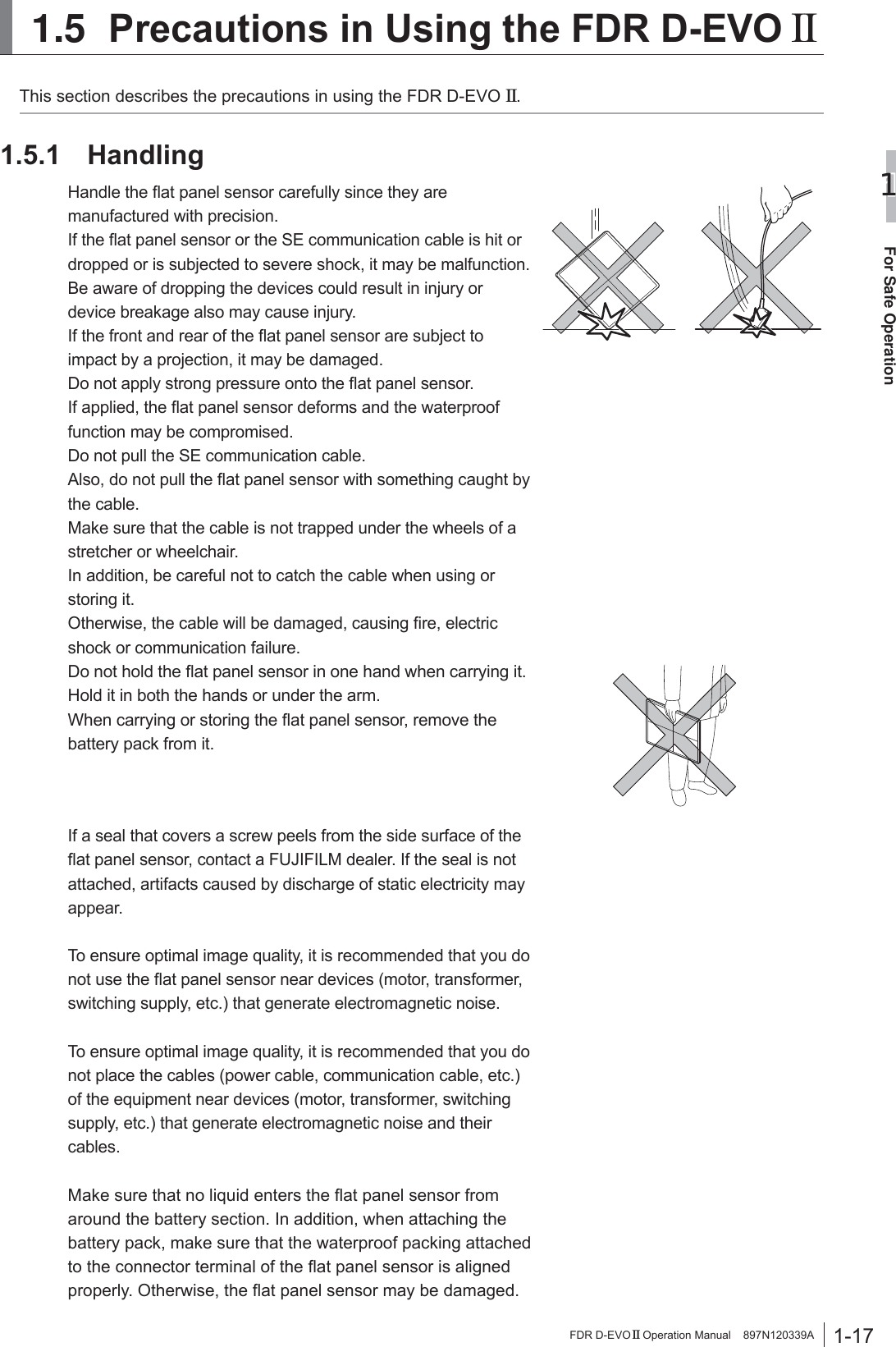
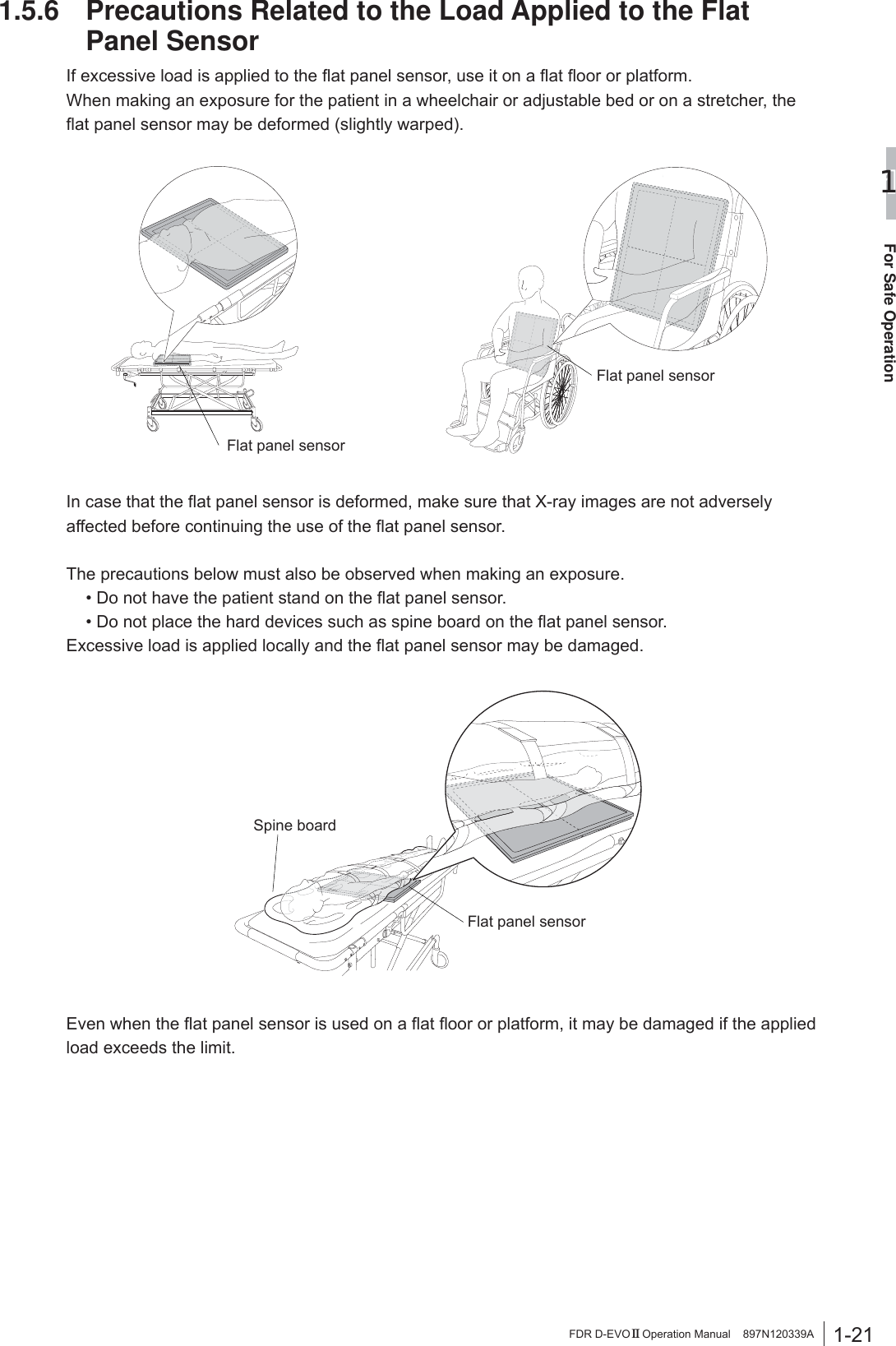
![1-18For Safe Operation1FDR D-EVO II Operation Manual 897N120339ADo not use a multiple tap connector or extension cable for powering the devices constituting the system.8SWR¿YHÀDWSDQHOVHQVRUVFDQEHFRQQHFWHG,I\RXLQWHQGWRXVHVL[RUPRUHÀDWSDQHOVHQVRUVRQO\WKH¿UVW¿YHWKDWwere connected to the image processing unit can be used.)RUWKLVUHDVRQZKHQVL[RUPRUHÀDWSDQHOVHQVRUVDUHregistered, be careful not to use a wrong one, as you may FRQIXVHZKLFKÀDWSDQHOVHQVRULVFRQQHFWHG%HIRUHPDNLQJDQH[SRVXUHPDNHVXUHWKDWWKHÀDWSDQHOVHQVRULGHQWL¿FDWLRQODPSRQWKHÀDWSDQHOVHQVRUWREHused and the panel icon selected on the screen of the image processing unit are the same color.:KHQDÀDWSDQHOVHQVRULVFRPPXQLFDWLQJZLWKDSRZHUsupply unit, docking stand or access point in a room, if the ÀDWSDQHOVHQVRULVPRYHGWRDQRWKHUURRPZKHUHWKHUHLVanother power supply unit, docking stand or access point, FRPPXQLFDWLRQEHWZHHQWKHÀDWSDQHOVHQVRUDQGWKHGHYLFHLQWKH¿UVWURRPPD\VWLOOEHHVWDEOLVKHG7RHVWDEOLVKFRPPXQLFDWLRQEHWZHHQWKHÀDWSDQHOVHQVRUDQGDGHYLFHLQWKHVHFRQGURRPFRQQHFWWKHÀDWSDQHOVHQVRUWRWKHdevice with the cable or insert it into the docking stand. The ÀDWSDQHOVHQVRULVUHFRJQL]HGDQGZLUHOHVVFRPPXQLFDWLRQbecomes available.'RQRWSODFHWKHFDEOHWHUPLQDORQWKHÀRRUDVGRLQJVRPD\cause infection.Also, clean the cable and the terminal periodically.'RQRWLQVHUWWKHÀDWSDQHOVHQVRULQWRD&5UHDGHUXQLW1.5.2 Before ExposureThe use of an air-conditioner may dramatically changes the temperature of the room where the system is installed. This may cause dew condensation on the system, resulting in quality problems. When an air-conditioner is used, change the temperature gradually to avoid temperature variation in order not to cause dew condensation.,IDQH[SRVXUHLVPDGHZLWKWKHIURQWDQGUHDURIWKHÀDWSDQHOsensor facing the other way round, not only the re-exposure is required but electric parts of inside the equipment may be damaged.Exposure plane of the flat panel sensor](https://usermanual.wiki/Fuji-Film/01000006.Short-Term-Confidential-User-Manual-1/User-Guide-2473601-Page-32.png)
![1-20For Safe Operation1FDR D-EVO II Operation Manual 897N120339A:KHQWKH6(FRPPXQLFDWLRQFDEOHLVFRQQHFWHGWRWKHÀDWSDQHOVHQVRUWRPDNHDQH[SRVXUHon a bed, follow the precautions below. Otherwise a load may be applied locally to the SE FRPPXQLFDWLRQFDEOHFRQQHFWRUVFDXVLQJGDPDJHWRWKHÀDWSDQHOVHQVRUMake sure that the connector does not protrude from the edge of a bedDo not place the connector on a hard surface such as the edge of a bedDo not raise the flat panel sensor by holding only the connector 'XULQJ&OHDQLQJ To clean the outer surfaces, use a cleaning cloth tightly wrung out of commercially available ethanol (or diluted neutral detergent). CAUTIONSƔ %HVXUHWRWXUQRIIWKHSRZHUEHIRUHFOHDQLQJHDFKSDUWRIWKHGHYLFHƔ 'RQRWXVHDQH[FHVVLYHDPRXQWRIHWKDQRORUQHXWUDOGHWHUJHQWDVGRLQJVRPD\DOORZWKHOLTXLGWRHQWHUIURPWKHJDSRQWKHRXWHUVXUIDFHVUHVXOWLQJLQWKHGDPDJHWRWKHÀDWSDQHOsensor, or cause the labels to come off.Ɣ 'RQRWXVHDVROYHQWVXFKDVWKLQQHURUEHQ]LQHDVLWFRUURGHVWKHRXWHUVXUIDFHVƔ )RURWKHUDYDLODEOHGLVLQIHFWDQWVFRQVXOWRXURI¿FLDOGHDOHU 6WRUDJH:KHQWKHÀDWSDQHOVHQVRUDQGWKHLPDJHSURFHVVLQJXQLWDUHQRWLQXVHVWRUHWKHPLQDSODFHwhere they do not fall or drop.](https://usermanual.wiki/Fuji-Film/01000006.Short-Term-Confidential-User-Manual-1/User-Guide-2473601-Page-34.png)
![1-22For Safe Operation1FDR D-EVO II Operation Manual 897N120339A1.5.7 Radio Waves:LUHOHVVVSHFL¿FDWLRQVIRUWKHÀDWSDQHOVHQVRUDQGDFFHVVSRLQWDUHDVIROORZV)ODWSDQHOVHQVRU $FFHVVSRLQWRSWLRQDO:LUHOHVVVSHFLILFDWLRQ ,(((Q ,(((Q7UDQVPLWIUHTXHQF\ *+] *+]0RGXODWLRQ OFDM OFDM)UHTXHQF\WROHUDQFH SSP SSP'DWDWUDQVIHUUDWH 0ESV 0ESV7UDQVIHUSRZHU G%PRUOHVV G%PRUOHVV)RUZLUHOHVVVSHFL¿FDWLRQVRIWKHLPDJHSURFHVVLQJXQLWVHH³'5,'&/2SHUDWLRQ0DQXDO´CAUTIONSƔ Radio waves available outdoors vary, depending on the country where the system is used. (For U.S.) Radio waves in the 5.2GHz frequency band can be used indoors only. When radio waves in the 5.3GHz and 5.6GHz frequency bands are selected, the DFS function will operate. Ɣ When the FDR D-EVO II and any other wireless equipment are operating on the same frequency channel in a hospital, it may take time to show an image on the image processing unit monitor.CAUTIONS7KHDYDLODEOHVFLHQWL¿FHYLGHQFHGRHVQRWVKRZWKDWDQ\KHDOWKSUREOHPVDUHDVVRFLDWHGZLWKusing low power wireless devices. There is no proof, however, that these low power wireless devices are absolutely safe. Low power Wireless devices emit low levels of radio frequency energy (RF) in the microwave range while being used. Whereas high levels of RF can produce health effects (by heating tissue), exposure of low-level RF that does not produce heating effects causes no known adverse health effects. Many studies of low-level RF exposures have not found any biological effects. Some studies have suggested that some biological effects might occur, EXWVXFK¿QGLQJVKDYHQRWEHHQFRQ¿UPHGE\DGGLWLRQDOUHVHDUFK'5,'6('5,'6('5,'6('5,'6(KDVEHHQWHVWHGDQGIRXQGWRFRPSO\ZLWK)&&,&UDGLDWLRQH[SRVXUHOLPLWVVHWIRUWKIRUDQXQFRQWUROOHGHQYLURQPHQWDQGPHHWVWKH)&&UDGLRIUHTXHQF\5)([SRVXUH*XLGHOLQHVDQG566RIWKH,&UDGLRIUHTXHQF\5)([SRVXUHUXOHV/HVFRQQDLVVDQFHVVFLHQWL¿TXHVGRQWQRXVGLVSRVRQVQ¶RQWPLVHQpYLGHQFHDXFXQSUREOqPHGHVDQWpDVVRFLpjO¶XVDJHGHVDSSDUHLOVVDQV¿OjIDLEOHSXLVVDQFH1RXVQHVRPPHVFHSHQGDQWSDVHQPHVXUHGHSURXYHUTXHFHVDSSDUHLOVVDQV¿OjIDLEOHSXLVVDQFHVRQWHQWLqUHPHQWVDQVGDQJHU/HVDSSDUHLOVVDQV¿OjIDLEOHSXLVVDQFHpPHWWHQWXQHpQHUJLHUDGLRpOHFWULTXH5)WUqVIDLEOHGDQVOHVSHFWUHGHVPLFURRQGHVORUVTX¶LOVVRQWXWLOLVpV$ORUVTX¶XQHGRVHpOHYpHGH5)SHXWDYRLUGHVHIIHWVVXUODVDQWpHQFKDXIIDQWOHVWLVVXVO¶H[SRVLWLRQjGHIDLEOHV5)TXLQHSURGXLVHQWSDVGHFKDOHXUQ¶DSDVGHPDXYDLVHIIHWVFRQQXVVXUODVDQWp'HQRPEUHXVHVpWXGHVRQWpWpPHQpHVVXUOHVH[SRVLWLRQVDX[5)IDLEOHVHWQ¶RQWGpFRXYHUWDXFXQHIIHWELRORJLTXH&HUWDLQHVpWXGHVRQWVXJJpUpTX¶LOSRXYDLW\DYRLUFHUWDLQVHIIHWVELRORJLTXHVPDLVFHVUpVXOWDWVQ¶RQWSDVpWpFRQ¿UPpVSDUGHVUHFKHUFKHVVXSSOpPHQWDLUHV'5,'6('5,'6('5,'6('5,'6(DpWpWHVWpHWMXJpFRQIRUPHDX[OLPLWHVG¶H[SRVLWLRQDX[UD\RQQHPHQWVpQRQFpHVSRXUXQHQYLURQQHPHQWQRQFRQWU{OpHWUHVSHFWHOHVUqJOHVOHVUDGLRpOHFWULTXHV5)GHOD)&&OLJQHVGLUHFWULFHVG¶H[SRVLWLRQHWG¶H[SRVLWLRQDX[IUpTXHQFHVUDGLRpOHFWULTXHV5)&15GHO¶,&](https://usermanual.wiki/Fuji-Film/01000006.Short-Term-Confidential-User-Manual-1/User-Guide-2473601-Page-36.png)

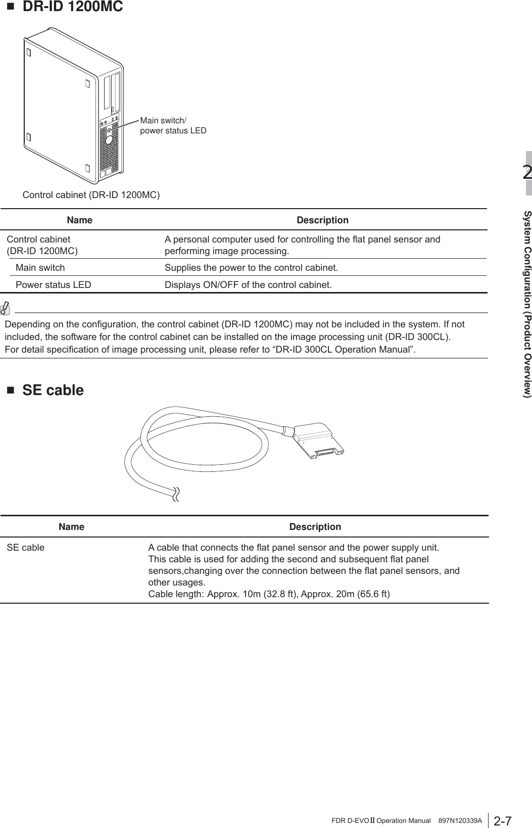
![2-8System Configuration (Product Overview)2FDR D-EVO II Operation Manual 897N120339AŶ SE communication cableName DescriptionSE communication cable $FDEOHXVHGIRUFRQQHFWLQJWKHÀDWSDQHOVHQVRUDQGWKHRSWLRQDODFFHVVSRLQWThis cable is used for wired communication if wireless communication is not available.,QDGGLWLRQWKLVFDEOHLVXVHGIRUUHJLVWHULQJRUUHFRJQL]LQJWKHÀDWSDQHOVHQVRU&DEOHOHQJWK$SSUR[PIWŶ %DWWHU\FKDUJHU2SWLRQDOBattery chargerName DescriptionBattery charger &KDUJHVWKHEDWWHU\SDFNIRUWKHÀDWSDQHOVHQVRU7ZRSDFNVFDQEHcharged at the same time.Charge status indicator LED Indicates charge status.Ŷ ,PDJHSURFHVVLQJXQLW For the unit names and functions of the image processing unit, see the “DR-ID 300CL Operation Manual”.](https://usermanual.wiki/Fuji-Film/01000006.Short-Term-Confidential-User-Manual-1/User-Guide-2473601-Page-54.png)
![2-14System Configuration (Product Overview)2FDR D-EVO II Operation Manual 897N120339A2.5 Wireless Specifications 7HFKQLFDO6SHFL¿FDWLRQIEEE802.11n (protocol) , 2.4GHz, W52, W53, W56, W58 (frequency) ,QWHQGHGHQYLURQPHQW5RRPVL]HRIP[P[PIW[IW[IWKHLJKWRUless (general X-ray room) (The electric shield does not exist excluding the installation stand or bed.) ,QVWDOODWLRQ'RQRWSODFHGHYLFHVJHQHUDWLQJHOHFWURPDJQHWLFZDYH&705,GLDWKHUP\ RFID etc.) near this equipment. We recommend not to use any other wireless devices such as cellular/smart phones, portable phones, microwave ovens, WAPs, etc. within 2m (6.6 ft) of the wireless FDR D-EVO II system. When other wireless devices are used within 2m (6.6 ft), wireless data communication may be delayed. (Data will not be lost; if a timeout occurs a retry can be performed after the cause of interference has been removed) Do not cover the Flat Panel Sensor (DR-ID 1201SE/DR-ID 1202SE/DR-ID 1211SE/DR-ID 1212SE) with a shield such as a metallic plate as this will interfere with a wireless communication. ,QIRUPDWLRQEHLQJWUDQVPLWWHG6\VWHP&RQWURO6LJQDO,PJBUHTB&0'HWF Image Data of the Flat Panel Sensor 1RWH3DWLHQW,QIRUPDWLRQLVQRWWUDQVPLWWHGE\ZLUHOHVV interface of Access point :LUHOHVVUDQJHPD[PIWIURPWKH$FFHVVSRLQWDVWHVWHG$FWXDOUDQJHPD\YDU\ 'DWDWUDQVIHUUDWH0ESV'5,'EHWZHHQWKH)ODW3DQHO6HQVRUDQG&RQVROH3& (This value is FUJIFILM measuring result of wireless module, and actual data rate may vary.) 7UDQVIHU3RZHUG%PRUOHVV 0RGXODWLRQ2)'03URYLGHGE\,(((Q :LUHOHVV'DWD6HFXULW\:LUHOHVV)'5'(92II system (DR-ID 1201SE/DR-ID 1202SE/DR-ID 1211SE/DR-ID 1212SE) will be utilizing the IEEE 802.11n. The Wireless Access Point (WAP) has a feature that limits the maximum number of the Flat Panel Sensor per access point to ensure data integrity. Further the WAP has MAC Address Filtering (unique IP address) and Wireless LAN Segmentation to ensure handshaking with only the registered wireless FDR D-EVO II Flat Panel Sensors (DR-ID 1201SE/DR-ID 1202SE/DR-ID 1211SE/ DR-ID 1212SE). ,QDGGLWLRQWRWKH0$&DGGUHVV¿OWHULQJWKHZLUHOHVVcommunication between DR-ID 1201SE/DR-ID 1202SE/DR-ID 1211SE/DR-ID 1212SE (Flat Panel Sensor) and access point is secured by WPA2-PSK encryption with AES (Advanced Encryption Standard). Data security feature will be enabled during installation E\D)8-,),/0¿HOGVHUYLFHHQJLQHHU1RSDWLHQWLQIRUPDWLRQis transmitted between DR-ID 1201SE/DR-ID 1202SE/DR-ID 1211SE/DR-ID 1212SE (Flat Panel Sensor) and access point., between access point and the console. +DQGVKDNLQJ3DLULQJ7KH:LUHOHVV$FFHVV3RLQWDQG'5,'6('5,'6('5ID 1211SE/DR-ID 1212SE (Flat Panel Sensor) will be paired during LQVWDOODWLRQE\D)8-,),/0¿HOGVHUYLFHHQJLQHHUWRHQVXUHRQHWRRQHZLUHOHVVFRQQHFWLRQ)8-,),/0¿HOGVHUYLFHHQJLQHHUZLOOPHDVXUHthe wireless transmission condition in the primary area, so the FDR D-EVO II system can be used stable. )UHTXHQF\7ROHUDQFHSSP](https://usermanual.wiki/Fuji-Film/01000006.Short-Term-Confidential-User-Manual-1/User-Guide-2473601-Page-60.png)
![3-4Basic Operation3FDR D-EVO II Operation Manual 897N120339A[2] Bed typeCAUTIONS:KHQLQVHUWLQJWKHÀDWSDQHOVHQVRUWRWKHUDGLRJUDSKLFH[DPLQDWLRQVWDQGdirect the exposure plane upwards.1 3XOORXWWKHWUD\E\XVLQJWKHKDQGOHTray2 3XOOWKHFDVVHWWHVWRSSHUDQGVHWWKHÀDWSDQHOVHQVRUVRWKDWLWVFHQWHUPDUNLVDOLJQHGZLWKWKHFHQWHURIWKHVWRSSHUCassette stopperCenter mark3 3XVKWKHWUD\EDFNLQWRSODFHE\XVLQJWKHKDQGOHDIWHUVHWWLQJWKHÀDWSDQHOVHQVRU4 5HPRYHWKHÀDWSDQHOVHQVRUDIWHUXVHHold the handle and pull out the tray. Remove the ÀDWSDQHOVHQVRUZKLOHSXOOLQJWKHFDVVHWWHVWRSSHUand then push the tray back into place. &KDQJLQJWKH'LUHFWLRQRIWKH)ODW3DQHO6HQVRUConnector7KHGLUHFWLRQRIWKHFRQQHFWRURIWKHÀDWSDQHOVHQVRUFDQEHFKDQJHGGHSHQGLQJRQKRZLWLVinserted into the radiographic examination stand. 7RFKDQJHWKHGLUHFWLRQFRQWDFWRXURI¿FLDOGHDOHURU)8-,),/05HSUHVHQWDWLYHWhen shipped After changing the direction](https://usermanual.wiki/Fuji-Film/01000006.Short-Term-Confidential-User-Manual-1/User-Guide-2473601-Page-66.png)
![3-19Basic Operation3FDR D-EVO II Operation Manual 897N120339A[3] Sleep modeWhen sleep mode is enabled, if no operation is performed for about two minutes without an exposure menu UHJLVWHUHGWKHÀDWSDQHOVHQVRUZLOOHQWHUVOHHSPRGHDQGWKHSRZHUVWDWHLVFKDQJHGWRWKHSRZHUVDYLQJVWDWHOnce an exposure menu is registered, sleep mode is canceled automatically. In addition, when the SE cable is FRQQHFWHGWRWKHÀDWSDQHOVHQVRURUZKHQWKHÀDWSDQHOVHQVRULVLQVHUWHGLQWRWKHGRFNLQJVWDQGVOHHSPRGHLVcanceled automatically.([WUDVOHHSPRGHZKLFKFDQIXUWKHUVDYHSRZHUFDQDOVREHVHW,IDVSHFL¿HGWLPHKDVHODSVHGDIWHUDOOÀDWSDQHOsensors enter sleep mode, they enter extra sleep mode. When the sleep release/memory exposure mode start button is pressed, extra sleep mode is canceled.In sleep mode or extra sleep mode, the operating time of the battery pack becomes longer since the power is saved. ,IWKHÀDWSDQHOVHQVRULVEHLQJFDOLEUDWHGRULILWGHWHFWVDQLPSDFWLWPD\WDNHORQJHUWLPHWRHQWHUVOHHSPRGHor sleep mode may be canceled temporarily. When the setting of sleep mode or extra sleep mode needs to be FKDQJHGFRQVXOWRXURI¿FLDOGHDOHURUORFDOUHSUHVHQWDWLYH>@([WHQGHG,PDJH5HDGRXWWhen the Extended Image Readout mode is enabled, a long exposure for up to ten seconds is available. To set the ([WHQGHG,PDJH5HDGRXWPRGHFRQVXOWRXURI¿FLDOGHDOHURUORFDOUHSUHVHQWDWLYH)RUGHWDLOVRQKRZWRXVHWKHExtended Image Readout mode, see the “Console Advance (DR-ID 300CL) Reference Guide”.](https://usermanual.wiki/Fuji-Film/01000006.Short-Term-Confidential-User-Manual-1/User-Guide-2473601-Page-81.png)
![3-21Basic Operation3FDR D-EVO II Operation Manual 897N120339A +RZWR/RDG,PDJHV1 &RQQHFWLQVHUWWKHÀDWSDQHOVHQVRUWRLQWReach device.(When the DR-ID 1200PU is used)&RQQHFWWKHÀDWSDQHOVHQVRUWRWKHSRZHUVXSSO\unit using the SE cable.Flat panel sensor Power supply unit(When the DR-ID 1200DU is used),QVHUWWKHÀDWSDQHOVHQVRULQWRWKHGRFNLQJVWDQG )RUGHWDLOVRQKRZWRLQVHUWWKHÀDWSDQHOVHQVRUinto the docking stand, see “3.1.10 Attaching the Flat Panel Sensor to the Docking Stand” on Page 3-8. 2 7RORDGLPDJHVVWRUHGRQWKHÀDWSDQHOVHQVRULQWRWKHLPDJHSURFHVVLQJXQLWGLVSOD\WKH³,PDJH5HDGHU6WDWXVZLQGRZ´RQWKHLPDJHSURFHVVLQJXQLWVHOHFWWKHÀDWSDQHOVHQVRUDQGWKHQ³*HW,PDJH)3'Æ &6/´,PDJHVVWRUHGLQWKHÀDWSDQHOVHQVRUDUHORDGHGonto the image processing unit. :KHQFDOLEUDWLRQRIWKHÀDWSDQHOVHQVRULVLQprogress, an error may occur.If this happens, wait for a while and then try image loading again. 3 'LVSOD\WKH³6WXG\VFUHHQ´RIWKHSDWLHQWFRUUHVSRQGLQJWRWKHORDGHGLPDJHVDQGVHOHFWWKHH[SRVXUHPHQXWREHOLQNHGZLWKWKHLPDJHV4 6HOHFWWKHVHOHFWRURIWKHÀDWSDQHOVHQVRULQZKLFKWKHLPDJHLVVWRUHGDQGWKHQVHOHFW>,PDJH%R[@5 2QWKH³,PDJH/LEUDU\VFUHHQ´VHOHFWWKHLPDJHRIZKLFKWKHQXPEHULVWREHOLQNHGwith the exposure menu and then select [Import]. HINT When an image that has not been linked with an exposure menu is left, if images are acquired from WKHÀDWSDQHOVHQVRUWKHDFTXLVLWLRQGDWHDQGWLPHis added to the image No. of the image that was acquired previously. For details, see the “Console Advance (DR-ID 300CL) Reference Guide”.](https://usermanual.wiki/Fuji-Film/01000006.Short-Term-Confidential-User-Manual-1/User-Guide-2473601-Page-83.png)
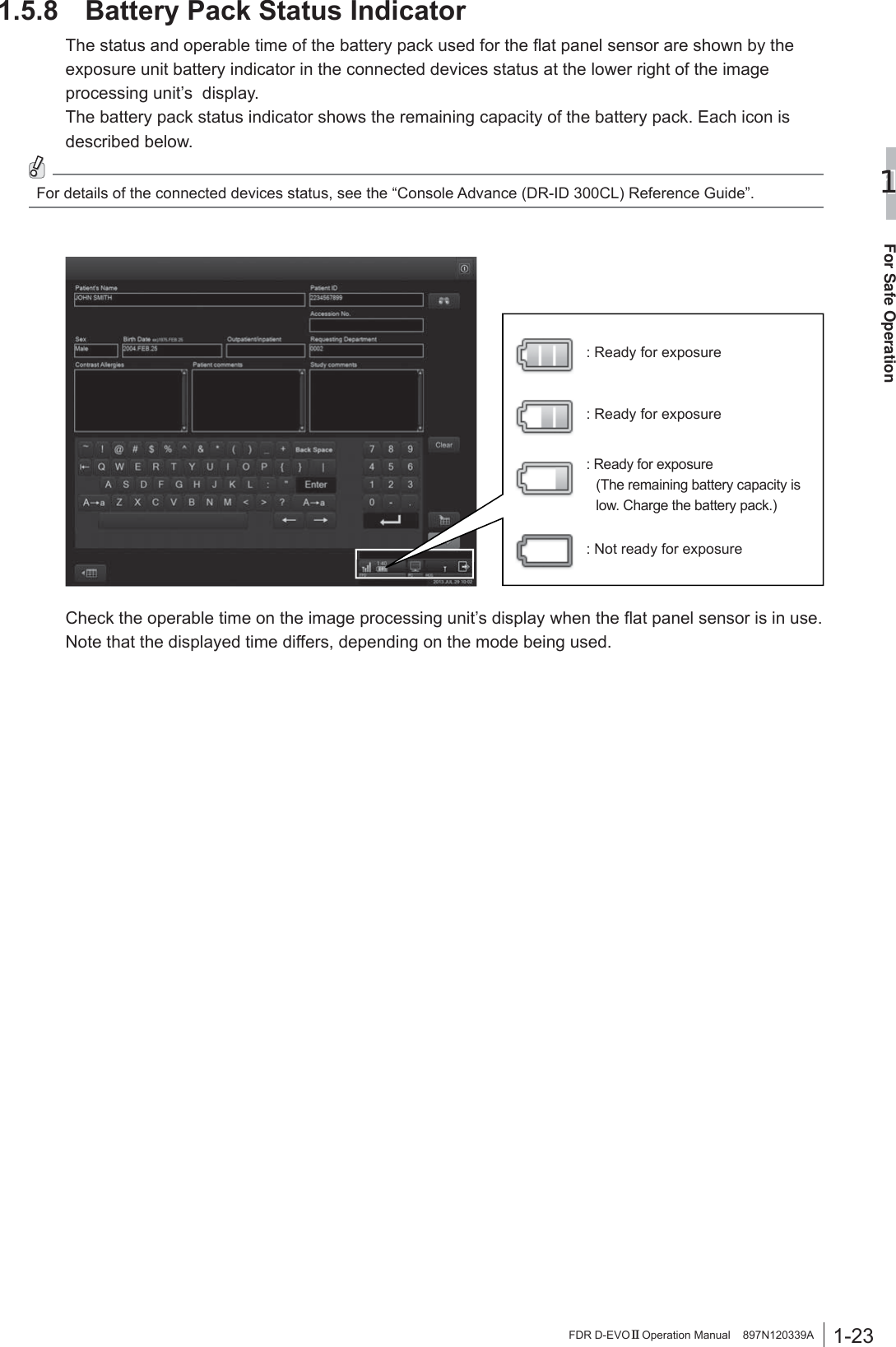
![4-1Troubleshooting4FDR D-EVO II Operation Manual 897N120339AChapter 47URXEOHVKRRWLQJ4.1 :KHQD0HVVDJH$SSHDUVRQWKH,PDJH3URFHVVLQJ8QLWThis section describes the warning dialog box and error messages. ,IDQHUURUZKLFKFDQQRWEHKDQGOHGRUWKHVDPHHUURUUHFXUVIUHTXHQWO\FRQWDFWRXURI¿FLDOGHDOHURUFUJIFILM Representative. ,IDQHUURURIXQNQRZQFDXVHRFFXUVGRQRWFRQWLQXHWKHRSHUDWLRQDQGFRQWDFWRXURI¿FLDOGHDOHURUFUJIFILM Representative. >@,IDZDUQLQJGLDORJER[DSSHDUVIf a communication error or an unexpected error has occurred, a warning dialog box pops up on the screen. In such a case, after checking error details and closing the box, take appropriate action immediately. Be sure not to continue the operation of the image processing unit without taking an appropriate action.If any operation is performed while a warning dialog box is displayed, another screen may be displayed, hiding the dialog box behind. In this case, press the [Enter] key to close the hidden box.When a warning dialog box that contains an error code beginning with “10” appears, follow the steps below.1 5HDGDPHVVDJHLQWKHZDUQLQJGLDORJER[DQGWKHQFOLFN>2.@LQWKHGLDORJER[2 'HWDFKWKHEDWWHU\SDFNVIRUDOOÀDWSDQHOVHQVRUV3 &RQ¿UPWKDWWKHÀDWSDQHOVHQVRUVDUHWXUQHGRII4 5HDWWDFKWKHEDWWHU\SDFNVWRWKHÀDWSDQHOVHQVRUV7KHQWKHV\VWHPUHVWDUWV>@,IWKHPHVVDJHGLDORJXHER[0'DSSHDUVThe following message dialogue box appears not only when the image processing unit starts up but DOVRZKHQDFRPPXQLFDWLRQHUURURFFXUVLQWKHÀDWSDQHOVHQVRURULPDJHSURFHVVLQJXQLW&KHFNLIWKHÀDWSDQHOVHQVRULVZLWKLQWKHUHDFKRIUDGLRZDYHV,IWKHXQLWLVRXWRIWKHUDQJHPRYHWKHLPDJHSURFHVVLQJXQLWDQGWKHÀDWSDQHOVHQVRUFORVHUWRHDFKRWKHU,QDGGLWLRQFRQ¿UPWKDWWKHUHDUHQRREVWDFOHVZKLFKDUHLQWHUUXSWLQJWKHFRPPXQLFDWLRQWhen the problem is not solved within a short time after the message box is displayed, perform the following procedure.](https://usermanual.wiki/Fuji-Film/01000006.Short-Term-Confidential-User-Manual-1/User-Guide-2473601-Page-85.png)
![4-3Troubleshooting4FDR D-EVO II Operation Manual 897N120339A2 If an exposure is made under a condition where wireless communication is unstable, the IROORZLQJPHVVDJHGLDORJPD\EHGLVSOD\HG6HOHFW³2.´WRDFTXLUHWKHLPDJHDQGWKHQFKHFNWKHDFTXLUHGLPDJH<Error message of “11409”>>@,IWKHGLDORJER[FRQWDLQLQJWKHHUURUPHVVDJHQXPEHUHG13048 appears7KHGLDORJXHER[DSSHDUVZKHQDVHYHUHVKRFNLVDSSOLHGWRWKHÀDWSDQHOVHQVRU0DNHVXUHWKDWWKHH[WHULRURIWKHÀDWSDQHOVHQVRULVQRWGDPDJHGRUGHIRUPHGDQGWKDWQRDEQRUPDOLW\LVIRXQGLQthe exposed image.[5] ,I³8QXVDEOHGXHWRHUURU´DSSHDUVRQWKHLPDJHSURFHVVLQJXQLWConnected devices status](https://usermanual.wiki/Fuji-Film/01000006.Short-Term-Confidential-User-Manual-1/User-Guide-2473601-Page-87.png)
![4-4Troubleshooting4FDR D-EVO II Operation Manual 897N120339AIf “Unusable due to error.” is displayed on the image processing unit, remove the battery pack from WKHÀDWSDQHOVHQVRUDQGLQVWDOOLWDJDLQBattery packGuide marksGuide marks>@,IDQ\RWKHUPHVVDJHGLDORJXHER[DSSHDUVIf a message dialogue box other than those [1] – [5] appears on the image processing unit monitor, read the message carefully and take appropriate action.](https://usermanual.wiki/Fuji-Film/01000006.Short-Term-Confidential-User-Manual-1/User-Guide-2473601-Page-88.png)
![4-5Troubleshooting4FDR D-EVO II Operation Manual 897N120339A4.2 How to Cope with an Error...>@:KHQWKHLPDJHSURFHVVLQJXQLWKDQJVXS«If an inappropriate processing is performed while this equipment is operating, the screen may freeze and the system may hang up (processing disabled). In that case, shut down the equipment forcibly according to the following procedure, and then restart it.1 3UHVVWKH>&WUO@>$OW@>'HO@NH\VVLPXOWDQHRXVO\2 ³:LQGRZV6HFXULW\´LVGLVSOD\HGSelect [Start Task Manager].3 ³:LQGRZV7DVN0DQDJHU´LVGLVSOD\HGSelect “ProcessManagerMain.exe” in the list in the “Processes” tab, and then click [End Process].4 7KHPHVVDJHER[LVGLVSOD\HGClick [End Process] to terminate the image processing unit.Depending on equipment status, an error message may not be displayed.5 7KHGHVNWRSVFUHHQRIWKHRSHUDWLQJV\VWHPLVGLVSOD\HGClose the “Windows Task Manager window”, and then select the [Start] button at the lower left of the screen. Select [Restart] from the displayed menu.CAUTIONSƔ 0DNHVXUHWRVKXWGRZQWKHV\VWHPIROORZLQJWKHDERYHSURFHGXUHVLQFDVHRIDKDQJXSRIWKHLPDJHSURFHVVLQJXQLW,IWKHSHUVRQDOFRPSXWHULVWXUQHGRIIZLWKRXWVKXWGRZQDQHUURUmay occur on the computer.Ɣ 1RWHWKDWIRUFLEOHVKXWGRZQSURFHVVLQJRIWKHHTXLSPHQWLVDQHPHUJHQF\DFWLRQ'RQRWXVHthis action under normal situations.6 If the control cabinet is included in the system, press and hold the main switch of the control cabinet to turn it off. 7 7XUQRIIWKHPDLQVZLWFKRQWKHSRZHUVXSSO\XQLWDQGRQWKHGRFNLQJVWDQG>@:KHQWKHLPDJHSURFHVVLQJXQLWLVWXUQHGRIIGXHWRDQHOHFWULFDORXWDJHWhen the image processing unit is turned off due to an electrical outage, etc., take the following actions according the condition when the power comes back on.Ŷ ,IWKHSRZHUFRPHVEDFNRQVRRQDIWHUDQHOHFWULFDORXWDJHWait until the image processing unit restarts. When the image processing unit has restarted, shut down the image processing unit by following the normal procedure. For details of system shutdown, see the “DR-ID 300CL Operation Manual”.To restart the image processing unit, follow the procedure for the system startup.](https://usermanual.wiki/Fuji-Film/01000006.Short-Term-Confidential-User-Manual-1/User-Guide-2473601-Page-89.png)
![4-6Troubleshooting4FDR D-EVO II Operation Manual 897N120339A>@,IDKDUGGLVNRIWKHLPDJHSURFHVVLQJXQLWLVGDPDJHGIf one of the hard disks is damaged, a window indicating so will appear. In such a case, press the )NH\DQGFRQWDFWRXURI¿FLDOGHDOHU>@,IDZKLWHLPDJHLVGLVSOD\HGDIWHUDQH[SRVXUHIf a white image is displayed, a LAN communication error may have occurred. &KHFNLIWKH/$1FRPPXQLFDWLRQFRQQHFWRUVDUHSURSHUO\FRQQHFWHGEHWZHHQWKHÀDWSDQHOVHQVRUand the power supply unit or and between the power supply unit and the control cabinet. Make an H[SRVXUHDJDLQDIWHUFRQ¿UPDWLRQ[5] Precautions for operation when the device status is ³,QLWLDOL]LQJ´RU³&KDQJLQJ)3'´LQWKHLPDJHSURFHVVLQJXQLW¶V³2XWSXW'HYLFH6WDWXVZLQGRZ´:KHQDÀDWSDQHOVHQVRULVDGGHGRUUHSODFHGRUZKHQWKHEDWWHU\RIDÀDWSDQHOVHQVRULVUHSODFHG³,QLWLDOL]LQJ´RU³&KDQJLQJ)3'´LVGLVSOD\HGIRUDOOWKHÀDWSDQHOVHQVRUVLQWKHGHYLFHVWDWXV¿HOGRIthe image processing unit’s “Output Device Status window”. While either of the status messages is displayed, you cannot make an exposure. Wait until the message disappears. :KHQWKHÀDWSDQHOVHQVRULVWXUQHGRQE\FRQQHFWLQJWKHFDEOHIRUZLUHGFRPPXQLFDWLRQRUE\attaching the battery pack immediately after the system starts up or an X-ray exposure is made, it may take time before the next exposure becomes available. (YHQLI³,QLWLDOL]LQJ´RU³&KDQJLQJ)3'´LVGLVSOD\HGIRUDOOWKHÀDWSDQHOVHQVRUVRQO\WKRVHZKLFKDUHDGGHGRUreplaced or those whose battery is replaced will be initialized.>@,IWKHÀDWSDQHOVHQVRUFDQQRWEHXVHGLQZLUHOHVVcommunication mode ,IWKHÀDWSDQHOVHQVRULVQRWUHFRJQL]HGLQDZLUHOHVVFRPPXQLFDWLRQPRGHXVHWKHFDEOHWRconnect the system in wired communication mode.](https://usermanual.wiki/Fuji-Film/01000006.Short-Term-Confidential-User-Manual-1/User-Guide-2473601-Page-90.png)
![4-77URXEOHVKRRWLQJ4FDR D-EVO II Operation Manual 897N120339A[7] If an error occurs on an output destination device If an error occurs on an output destination device, is displayed in the connected devices status. In such a case, operate as follows. Select . The “Output Device Status window” is displayed. Select after checking the connection status, and then take an appropriate action. “Output Device Status window“](https://usermanual.wiki/Fuji-Film/01000006.Short-Term-Confidential-User-Manual-1/User-Guide-2473601-Page-91.png)

 14” × 17” (b) 17” × 14” (c) 14” × 14” one-image output one-image output one-image output(14” × 17” film) (14” × 17” film)(14” × 17” film)ID informationImageImageID informationID informationImage(d) 18 × 43cm (e) 18 × 43cm (f) 18 × 43cm one-image output two-image output two-image output(14” × 17” film)ID information ID informationID information ID information(26 × 36cm film)(26 × 36cm film)ImageImageImageImageImage(g) Two-image outputID informationImage(26 × 36cm film)For one-image output using 17” × 14”, 14” × 17”, 14” × 14” or 18 × 43cm, images are output on 14” î´¿OP,QRWKHUFDVHVLPDJHVDUHRXWSXWRQîFP¿OPDepending on the printer connected or image processing unit software version used, image outputs in the following formats are available.VL]HRXWSXWRI´î´LPDJHRQ´î´¿OPVL]HRXWSXWRI´î´LPDJHRQ´î´¿OPDVZHOODVUHGXFHGLPDJHRXWSXWRQ¿OPVRIRWKHUVL]HVVL]HRXWSXWRI´î´LPDJHRQ´î´¿OP$ 5HGXFHG(TXLYDOHQW3HDNUHGXFHGHTXLYDOHQWRQWKHIURQWSDQHORIWKHÀDWSDQHOVHQVRUPP$O](https://usermanual.wiki/Fuji-Film/01000006.Short-Term-Confidential-User-Manual-1/User-Guide-2473601-Page-96.png)
![A-3Appendix A SpecificationsFDR D-EVO II Operation Manual 897N120339AA.1.4 Power Supply ConditionsŶ DR-ID 1200PU 5DWHGYROWDJH9a ,QSXWFXUUHQW $ )UHTXHQF\ +]Ŷ DR-ID 1200DU 5DWHGYROWDJH9a ,QSXWFXUUHQW $ )UHTXHQF\ +]Ŷ DR-ID 1200MC* 5DWHGYROWDJH9a ,QSXWFXUUHQW $ )UHTXHQF\ +] * Since the DR-ID 1200MC is general-purpose electrical equipment, the electric rating above is an example. A.1.5 Environmental ConditionsŶ DR-ID 1200PU2SHUDWLQJ&RQGLWLRQV 7HPSHUDWXUH &5+&5+ +XPLGLW\ 5+&5+&QRGHZFRQGHQVDWLRQ $WPRVSKHULFSUHVVXUHK3DK3D1RQRSHUDWLQJ&RQGLWLRQV (Environmental conditions under which power can be supplied) 7HPSHUDWXUH && +XPLGLW\ 5+5+QRGHZFRQGHQVDWLRQ $WPRVSKHULFSUHVVXUHK3DK3D6WRUDJH&RQGLWLRQV 7HPSHUDWXUH && +XPLGLW\ 5+5+QRGHZFRQGHQVDWLRQ $WPRVSKHULFSUHVVXUHK3DK3DŶ DR-ID 1200DU2SHUDWLQJ&RQGLWLRQV 7HPSHUDWXUH &5+&5+ +XPLGLW\ 5+&5+&QRGHZFRQGHQVDWLRQ $WPRVSKHULFSUHVVXUHK3DK3D1RQRSHUDWLQJ&RQGLWLRQV (Environmental conditions under which power can be supplied) 7HPSHUDWXUH && +XPLGLW\ 5+5+QRGHZFRQGHQVDWLRQ $WPRVSKHULFSUHVVXUHK3DK3D6WRUDJH&RQGLWLRQV 7HPSHUDWXUH && +XPLGLW\ 5+5+QRGHZFRQGHQVDWLRQ $WPRVSKHULFSUHVVXUHK3DK3D](https://usermanual.wiki/Fuji-Film/01000006.Short-Term-Confidential-User-Manual-1/User-Guide-2473601-Page-97.png)
![A-9Appendix A SpecificationsFDR D-EVO II Operation Manual 897N120339AA.3 Characteristics(1) Sensitometoric Response Characteristics and Dynamic RangeFDR D-EVO II has a linear response against the exposure range where it can depict the clinical information.7KHÀDWSDQHOVHQVRUFRYHUVDG\QDPLFUDQJHRIȝ*\DWOHDVWDW54$(2) Spatial Resolution PropertiesA typical MTF value of DR-ID 1201SE/DR-ID 1202SE at 1cyc/mm, RQA5 is 0.75 (high sharpness mode) and 0.60 (standard sharpness mode). A typical MTF value of DR-ID 1211SE/DR-ID 1212SE at 1cyc/mm, RQA5 is 0.80. The level of uncertainty is estimated as less than ±10% '4('HWHFWLYH4XDQWXP(I¿FLHQF\7\SLFDO'4(YDOXHRI'5,'6('5,'6(DWȝ*\LQF\FPPLV7\SLFDO'4(YDOXHRI'5,'6('5,'6(DWȝ*\LQF\FPPLVThe level of uncertainty is estimated as less than ±10%(4) DisplayTo deliver the detector characteristics above, it is recommended to use a monitor with the following VSHFL¿FDWLRQV Ɣ,PDJHPDWUL[VL]H0LQLPXP[SL[HOV'5,'6('5,'6( Ɣ,PDJHPDWUL[VL]H0LQLPXP[SL[HOV'5,'6('5,'6( Ɣ*UD\VFDOH0LQLPXPELW Ɣ',&20FDOLEUDWHG(5) Image Quality Evaluation )XML¿OPW\SLFDOO\FRQGXFWVUHDGHUVWXGLHVWKDWFRPSDUHQHZ)'5'(92II detector models to chosen PDUNHWHGGHYLFHV7KHVHVWXGLHVLQYROYLQJDQDVVHVVPHQWRILPDJHTXDOLW\E\ERDUGFHUWL¿HGUDGLRORJLVWVhave demonstrated that the images acquired using the FDR D-EVO II detectors are deemed to be of diagnostic capability. Additionally, reader studies have concluded that, when used in conjunction with FUJIFILM’s recommended exposure conditions as a reference, both the GOS-based and Csl-based FDR D-EVO II detectors can provide acceptable diagnostic capability and image quality at reasonably low dose levels typically used for pediatric use.(6) Typical Patient Dose$VZLWKDQ\QHZSURGXFWDSSOLFDWLRQ)XML¿OPSURYLGHVDSSOLFDWLRQVWUDLQLQJVXSSRUWWRHDFKFXVWRPHUto establish the dose levels that meet the image quality standards of the medical facility. As part of this training, we provide both recommended technique charts as well as guidance for optimizing AEC conditions for each detector type. When using any FDR D-EVO II detector, typical patient dose levels should not H[FHHGWKDWRIVFUHHQ¿OPRU&RPSXWHG5DGLRJUDSK\](https://usermanual.wiki/Fuji-Film/01000006.Short-Term-Confidential-User-Manual-1/User-Guide-2473601-Page-103.png)

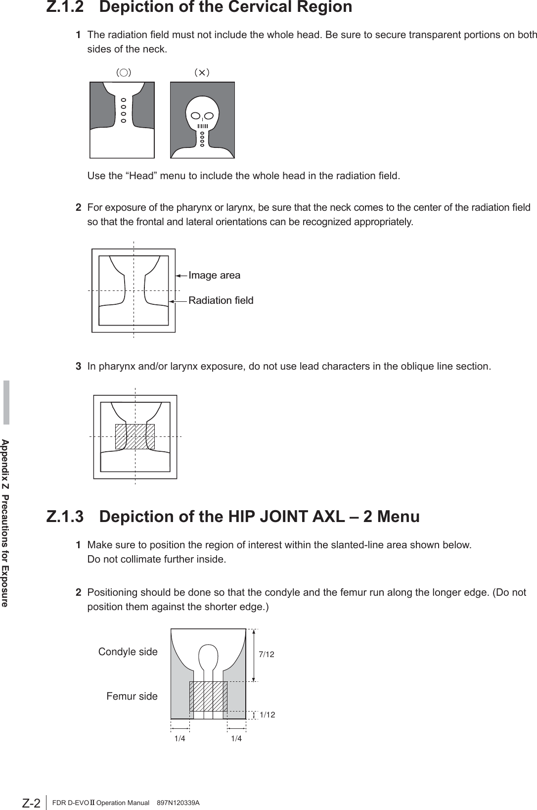
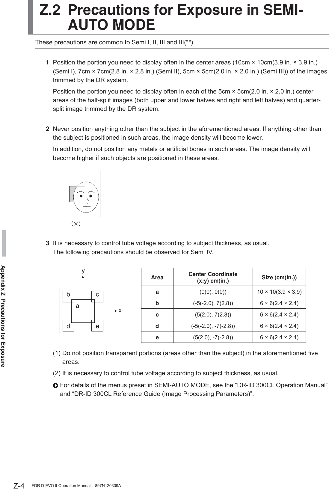
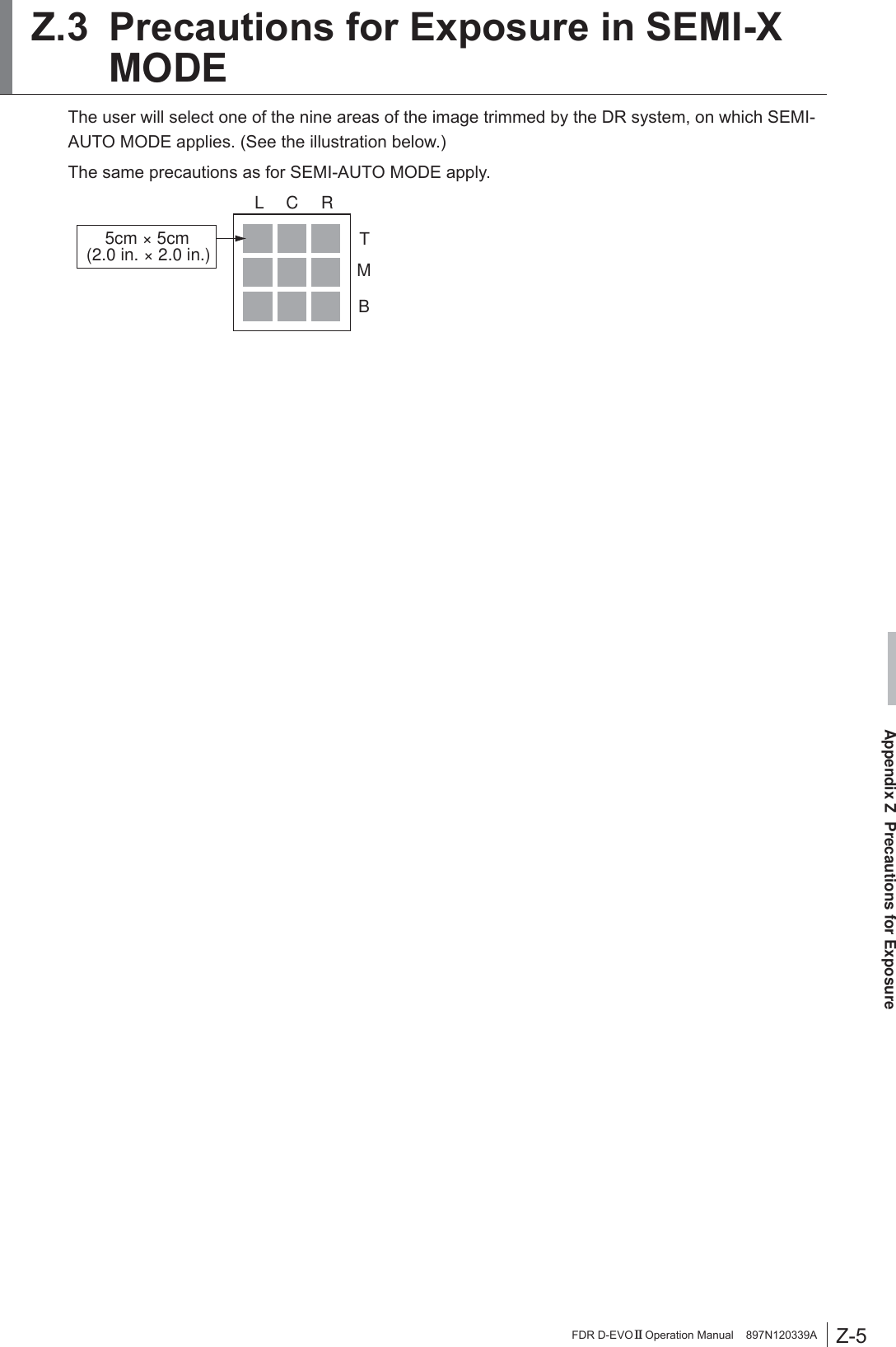
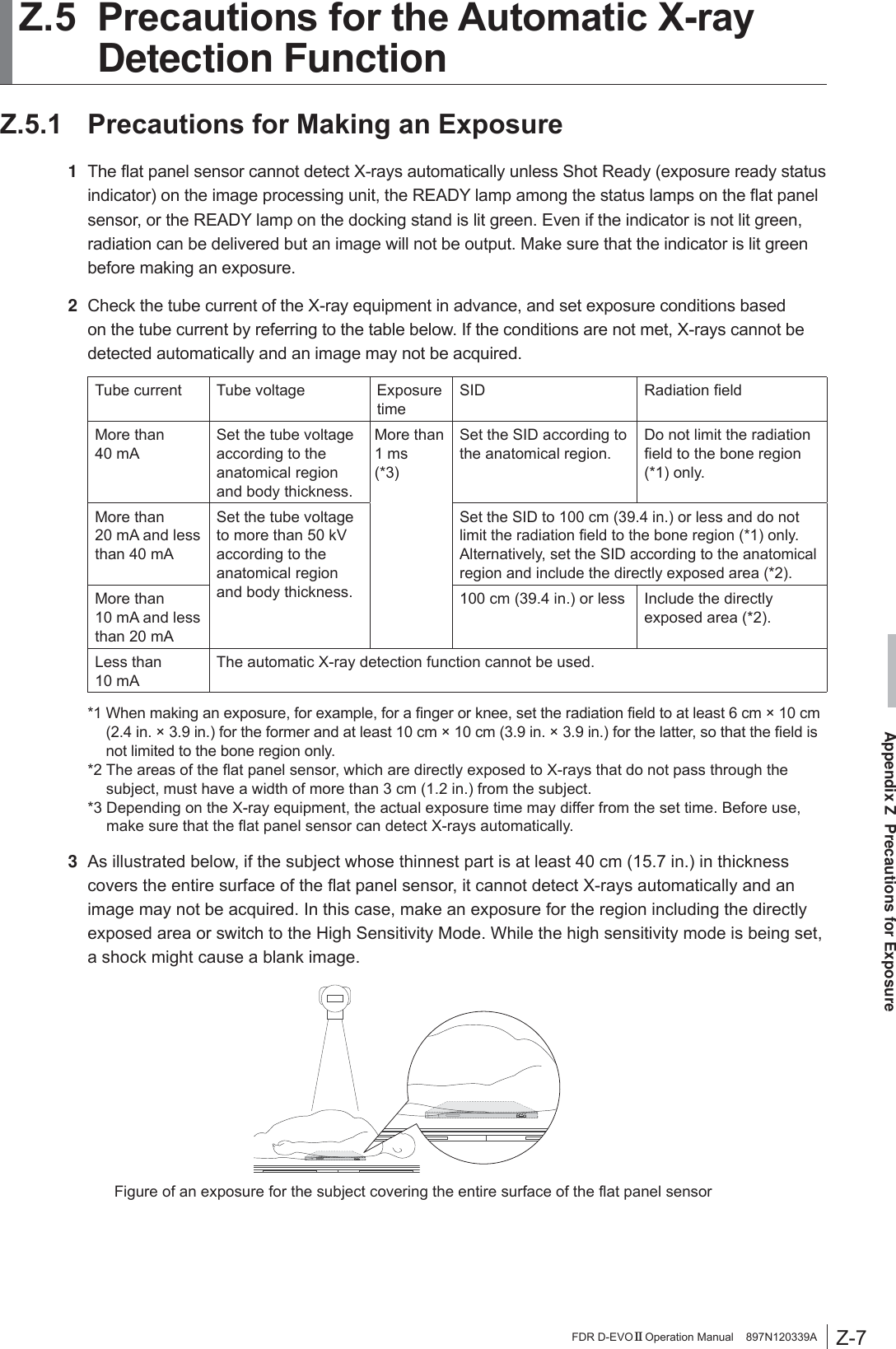
![Z-1Appendix Z Precautions for ExposureFDR D-EVO II Operation Manual 897N120339AAppendix Z Precautions for ExposureZ.1 Precautions for Exposure in AUTO MODEIn AUTO MODE, stable image output can be obtained by means of the following.5DGLDWLRQ¿HOG(2) EDR image data analysis(3) Detailed depiction of the cervical regionHowever, problems may arise due to differences in the multiple diaphragms or scattered rays of the ;UD\HTXLSPHQW)RUVXFKSUREOHPVFRQWDFWRXURI¿FLDOGHDOHURU)8-,),/05HSUHVHQWDWLYHDQGXVHother recording modes, such as SEMI-AUTO MODE or FIX MODE.Z.1.1 Radiation Field1 'RQRWVHWWKHUDGLDWLRQ¿HOGH[WUHPHO\VPDOO%HVXUHWRVXEMHFWRQHWKLUGRUPRUHRIWKHOHQJWKRIeach side of the bucky of the DR system to X-ray exposure.2 0DNHVXUHWKDWQRQHRIWKHVLGHVRIWKHUDGLDWLRQ¿HOGRYHUODSZLWKWKHFRQWUDVWPHGLXP(UURUVZLOOresult if they overlap. $YDLODEOHIRU(DFK$QDWRPLFDO5HJLRQ0HWKRGPlain Contrast Medium 7RPRJUDSK\Head 4 4 4 1HFN 4 4 – Chest 4 4 (1 for esophagus) – Abdomen 4 4 (1 for stomach and intestines) – Pelvis 4 4 – 3 Notes on PRIEF[PRIEF 4] Used, with some exceptions, for both plain and contrast medium exposure menus, from the head to the pelvis. The diaphragm shape will be any convex polygon, including rectangles, circles, ellipses, tracks, etc.[PRIEF 1] Used with esophagus, stomach and intestines contrast medium menus.](https://usermanual.wiki/Fuji-Film/01000006.Short-Term-Confidential-User-Manual-1/User-Guide-2473601-Page-105.png)
![Z-3Appendix Z Precautions for ExposureFDR D-EVO II Operation Manual 897N120339A= ('5,PDJH'DWD$QDO\VLV1 Image unevenness due to grid misalignment, X-ray beam misalignment, or shadow of clothes may cause EDR image data analysis problems resulting in unstable density on the image.2 If the target includes such materials as gypsum, denture, etc., stable density may not be obtained, EHFDXVHVXFKPDWHULDOVPDNHLWGLI¿FXOWWRDQDO\]H('5LPDJHGDWD In such cases, use FIX MODE.3 The EDR performs processing for the image area trimmed by the DR system. :KHQXVLQJOHDGFKDUDFWHUVRUPHWDOVIRUPHDVXUHPHQWSODFHWKHPLQVLGHWKHUDGLDWLRQ¿HOGDQGthen make an exposure.4 Precautions when using AUTO MODE.Auto mode PrecautionsI As this mode is available for extracting information on the skin, secure the positioning so that the direct X-rays are incident to an area other than the target.II No special precautions.III Be sure to use a Ba contrast medium.IV 1 Be sure to secure the positioning so that the X-rays are incident to the area directly outside the target.$VWKHUHDGLQJODWLWXGHLV¿[HGLWLVQHFHVVDU\WRFRQWUROWKHWXEHYROWDJHDFFRUGLQJWRWKHthickness of the target, as usual.V $VWKHUHDGLQJODWLWXGHLV¿[HGLWLVQHFHVVDU\WRFRQWUROWKHWXEHYROWDJHDFFRUGLQJWRWKHthickness of the target, as usual.VI No special precautions.VII No special precautions.](https://usermanual.wiki/Fuji-Film/01000006.Short-Term-Confidential-User-Manual-1/User-Guide-2473601-Page-107.png)
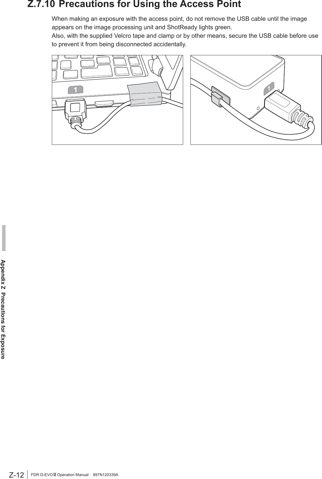
![Z-10Appendix Z Precautions for ExposureFDR D-EVO II Operation Manual 897N120339AZ.7 Other PrecautionsZ.7.1 Precautions for Exposure of a Subject in Relatively /DUJH&RQWUDVW1 Exposures using a contrast medium may cause artifacts around it.2 When exposing a subject with any metal objects implanted, artifacts may appear around them.3 For exposures with objects of large X-ray absorption, such as lead characters and metals for measurement, artifacts may appear around them. Place such objects outside a subject.Z.7.2 Precautions for Flat Panel Sensor*HQHUDOO\ZKHQSHUIRUPLQJDKLJKVHQVLWLYLW\H[SRVXUHVKRUWO\DIWHUDQH[SRVXUHWKDWWKHÀDWpanel sensor excessively receives direct X-ray, the output image may contain image lags of the previous exposure. This phenomenon rarely occurs and does not occur insofar as normal sensitivity exposures are performed.Exposures at longer intervals can reduce occurrences of this phenomenon. Also observe precautions as follows.• Continuous high sensitivity exposures to vertebral body part (chest/lumbar spine) should be performed at longer intervals than normal exposures. $KLJKVHQVLWLYLW\H[SRVXUHVKRUWO\DIWHUDKLJKGRVHH[SRVXUHVKRXOGEHSHUIRUPHGDWVXI¿FLHQWO\long interval. :KHQSHUIRUPLQJKLJKGRVHH[SRVXUHVUHSHDWHGO\GRQRWXVHFROOLPDWLRQRIWKHUDGLDWLRQ¿HOGlead characters or metals for measurement at the same position.= 3UHFDXWLRQVIRU$VVXULQJWKH5DGLDWLRQ)LHOGCAUTIONSƔ ,WLVLPSRUWDQWWRUHDGWKHIROORZLQJEHIRUHXVLQJWKH)'5'(92IIGLJLWDOGHWHFWRUFOLQLFDOO\Ɣ 'RQRWPDNHWKHUDGLDWLRQ¿HOGODUJHUWKDQWKHVL]HRIWKHÀDWSDQHOVHQVRU(VSHFLDOO\ZKHQWKHKLJKWXEHYROWDJHLVVHWWKHUDGLDWLRQ¿HOGVL]HVKRXOGQRWEHODUJHUWKDQWKHVXEMHFWunless necessary.The FDR D-EVO II is a digital X-ray detector designed for use both within and outside of a standard UDGLRJUDSKLFEXFN\5DGLDWLRQ¿HOGFDQEHVHWXSWR´î´'5,'6('5,'6(RUXSto 17” × 17” (DR-ID 1202SE/DR-ID1212SE) and this product may be used with the X-ray equipment LQDQ\VLWXDWLRQZKHUHD¿OPFDVVHWWHPD\EHXVHGThe collimator will open up to 14”× 17” for DR-ID 1201SE/DR-ID 1211SE and 17”× 17” for DR-ID 1202SE/DR-ID 1212SE, when the FDR D-EVO II cassette is inserted in the bucky tray of the X-ray equipment with positive beam limitation (PBL).)ROORZWKH;UD\V\VWHPPDQXIDFWXUHU¶VLQVWUXFWLRQVWRDVVXUHWKHLQGLFDWHG¿HOGVL]HPDWFKHVDQGGRHVQRWH[FHHGWKHDFWXDOUDGLDWLRQ¿HOGVL]HIRUWKHDYDLODEOHUDQJHRI6,'V= ,PDJHV2XWSXW:KHQWKH;UD\6KRW6ZLWFKLV2SHUDWHGIncorrectlyIn case that you press the X-ray shot switch only momentarily after selecting exposure menus, VXI¿FLHQW;UD\GRVHPD\QRWEHDFKLHYHG7KHRXWSXWLPDJHFRQWDLQVLPDJHODJVRIWKHSUHYLRXVexposure occasionally.If this happens, select exposure menus again, and then make an exposure.](https://usermanual.wiki/Fuji-Film/01000006.Short-Term-Confidential-User-Manual-1/User-Guide-2473601-Page-114.png)
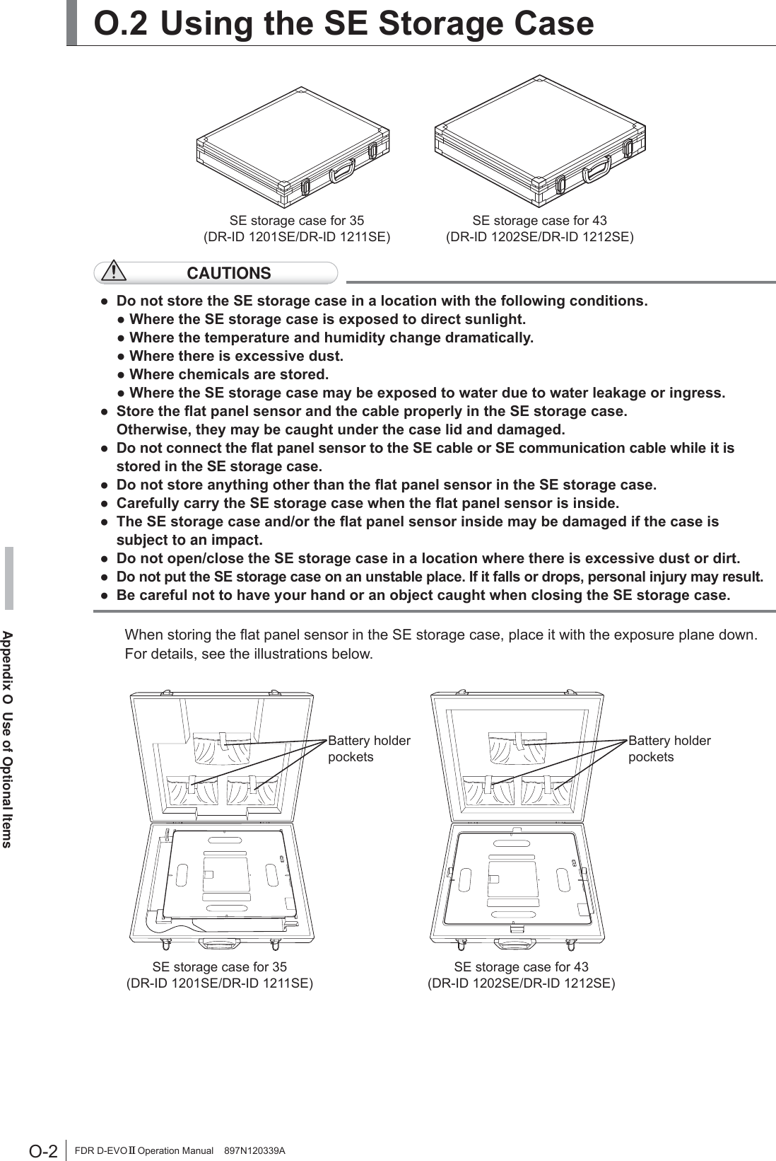
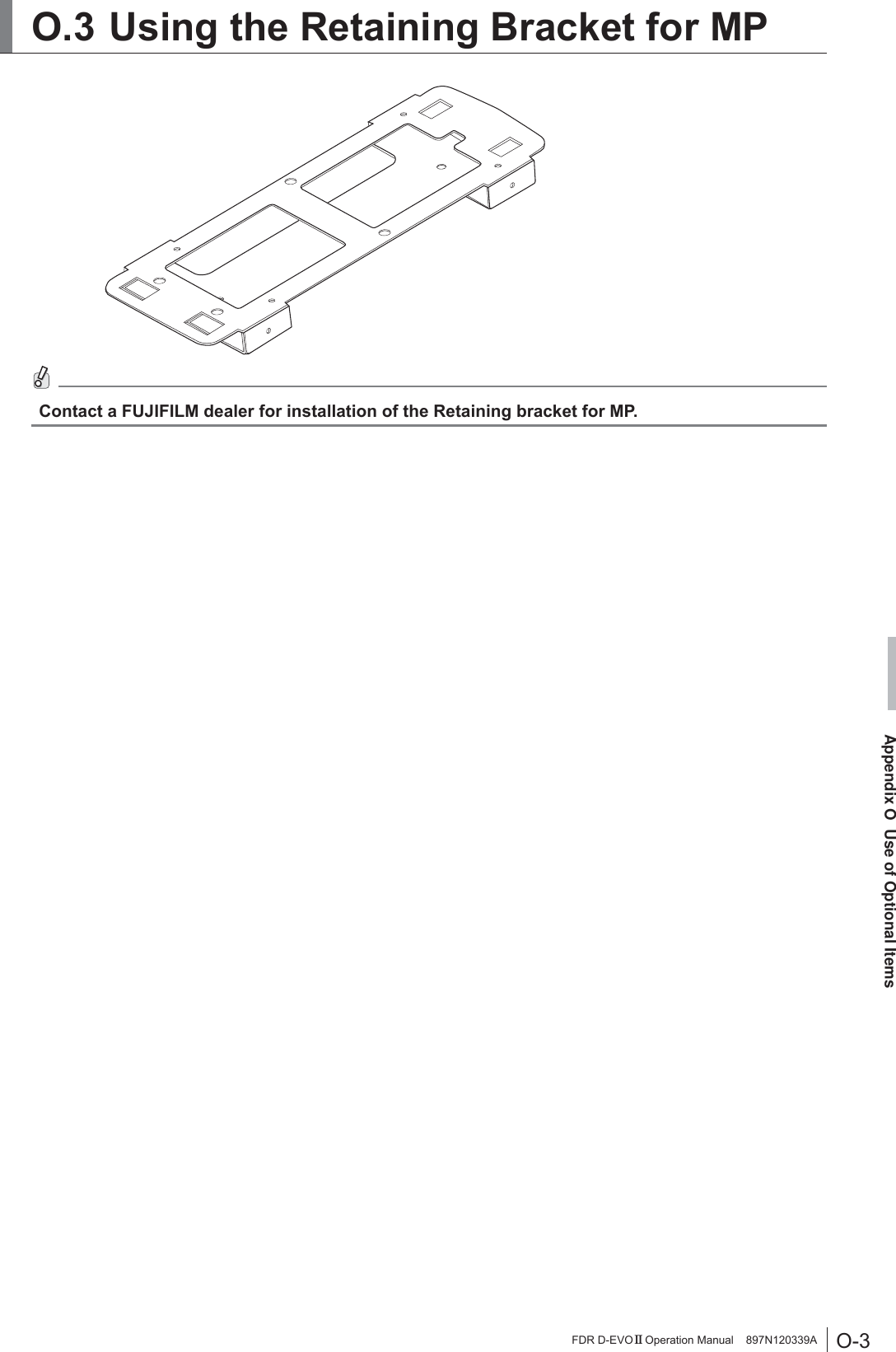
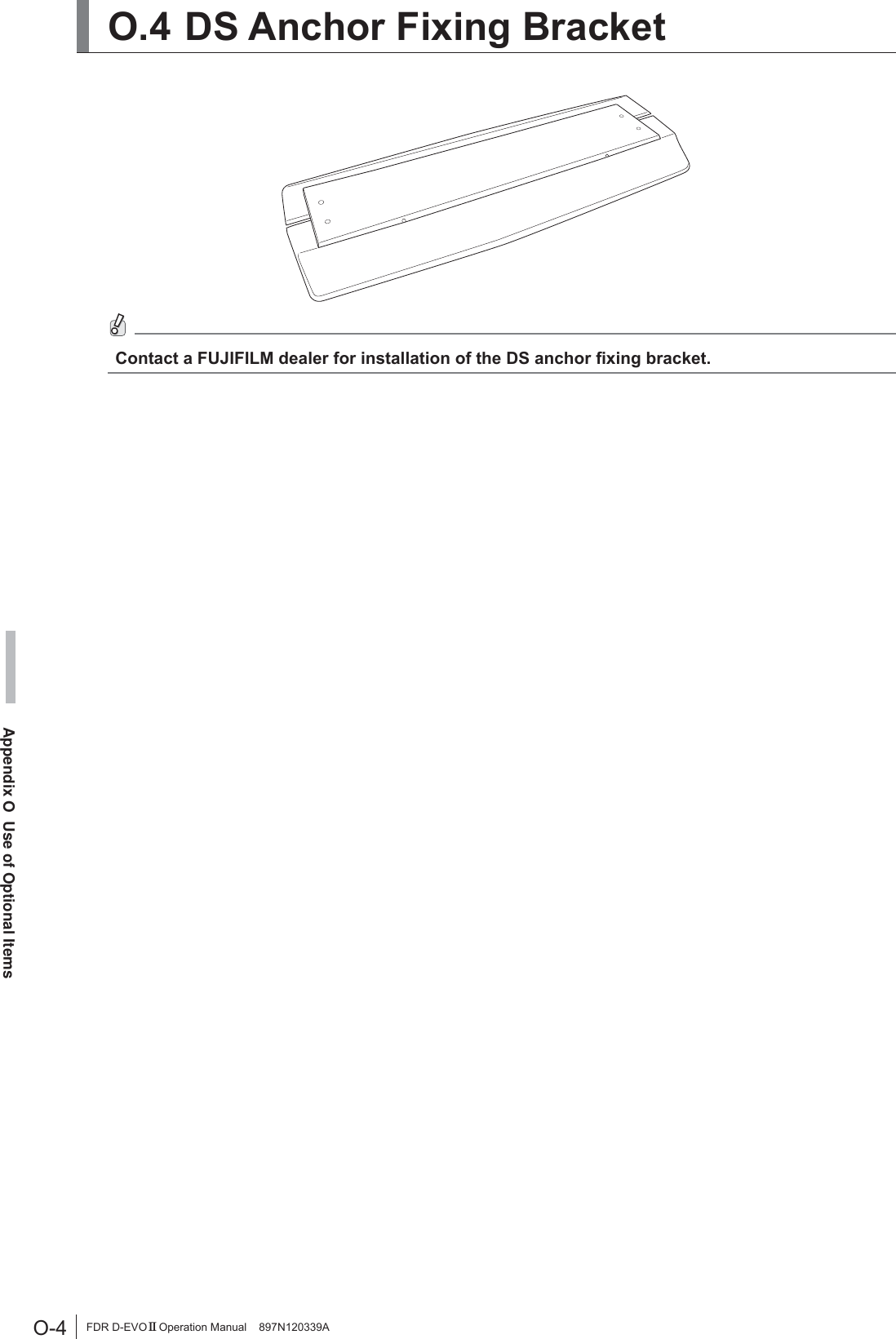
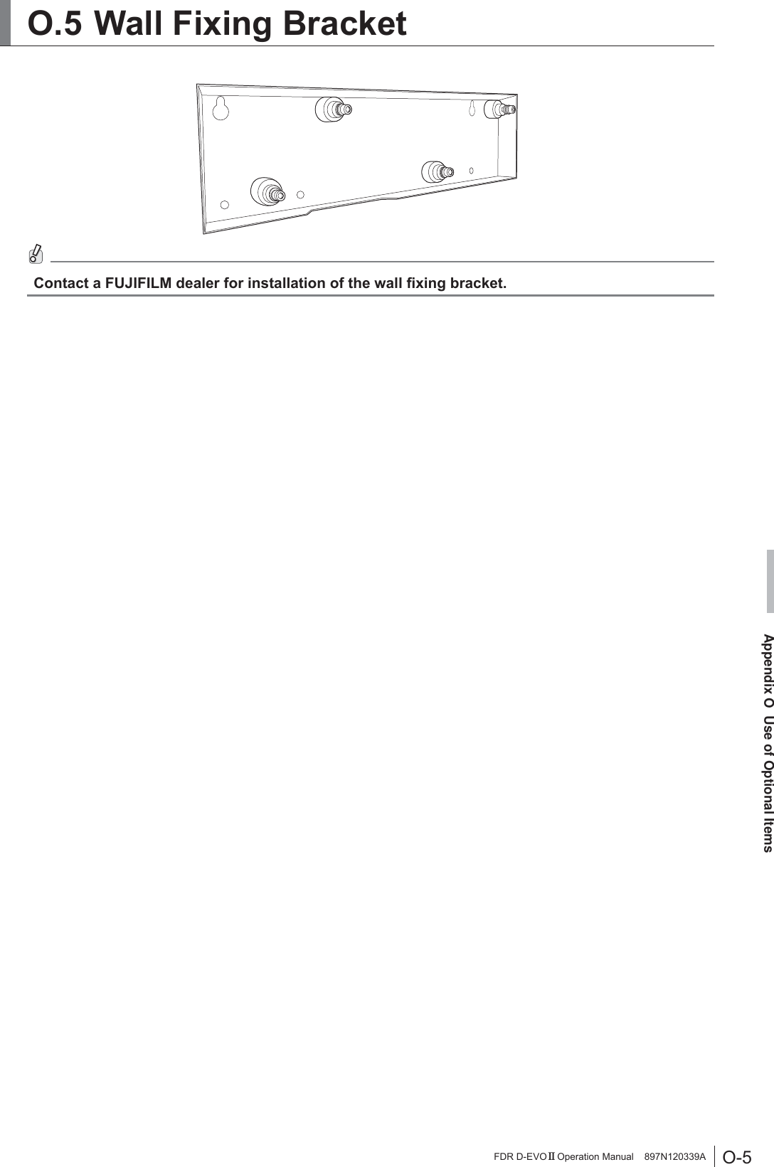
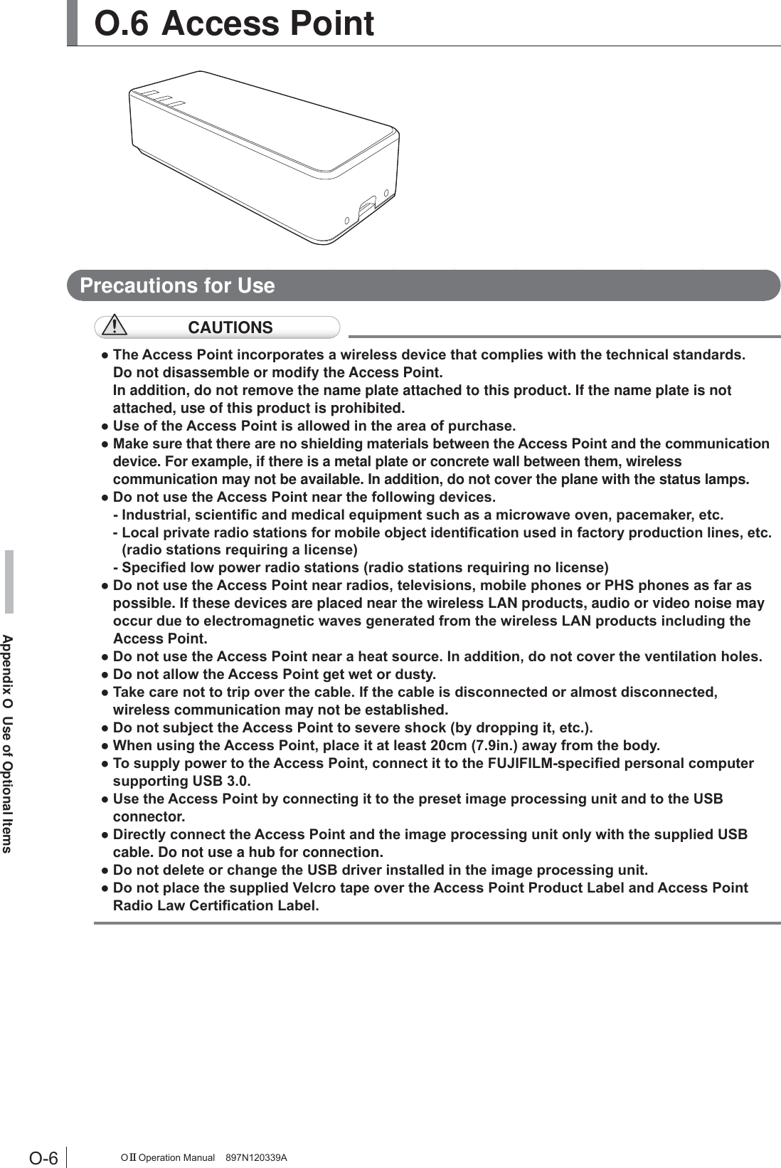
![O-1Appendix O Use of Optional ItemsFDR D-EVO II Operation Manual 897N120339AAppendix O Use of Optional ItemsO.1 Optional Items Name DescriptionSE storage case $FDVHXVHGIRUFDUU\LQJDQGVWRULQJWKHÀDWSDQHOVHQVRU For the external view and precautions, see “O.2 Using the SE Storage Case” (page O-2).Battery pack $EDWWHU\SDFNIRUWKHÀDWSDQHOVHQVRU For precautions, charging and installing/removing, see pages 1-8, 1-9, 3-6, 3-7 and 3-8.Battery charger A battery charger for the battery pack. For precautions, external view and charging, see pages 1-8, 1-9, 2-5, 3-6 and 3-7.Retaining bracket for MP $VHWRIDQDQFKRUDQGD¿[WXUHZKLFKLVXVHGIRUVHFXULQJWKHSRZHUVXSSO\XQLWWRWKHÀRRU For the external view, see “O.3 Using the Retaining bracket for MP” (page O-3).SE cable $FDEOHWKDWFRQQHFWVWKHÀDWSDQHOVHQVRUDQGWKHSRZHUVXSSO\XQLW7KLVFDEOHLVXVHGIRUDGGLQJWKHVHFRQGDQGVXEVHTXHQWÀDWSDQHOVHQVRUVFKDQJLQJRYHUWKHFRQQHFWLRQEHWZHHQWKHÀDWSDQHOVHQVRUVDQGother usages.Relay unit for AC bucky A relay unit consisting of the relay and terminal block for the AC bucky. )RXUW\SHVDUHDYDLODEOH)RU999DQG90DJQHWLFFODPSIRUÀDWSDQHOsensor cable$FODPSIRU¿[LQJWKH6(FDEOHWRWKHUDGLRJUDSKLFH[DPLQDWLRQVWDQGHWFAdapter for the docking stand $QDGDSWHUXVHGIRUDWWDFKLQJWKHÀDWSDQHOVHQVRUWRWKHGRFNLQJVWDQGDS Anchor Fixing Bracket $QDQFKRUDQG¿[LQJWRROVHWXVHGIRU¿[LQJWKHGRFNLQJVWDQGWRWKHÀRRU For the external view, see “O.4 DS Anchor Fixing Bracket” (page O-4).Wall Fixing Bracket $QDQFKRUDQG¿[LQJWRROVHWXVHGIRU¿[LQJWKHGRFNLQJVWDQGWRWKHÀRRU For the external view, see “O.5 Wall Fixing Bracket” (page O-5).SE communication cable$FDEOHXVHGIRUFRQQHFWLQJWKHÀDWSDQHOVHQVRUDQGWKHRSWLRQDODFFHVVSRLQWThis cable is used for wired communication if wireless communication is not available.,QDGGLWLRQWKLVFDEOHLVXVHGIRUUHJLVWHULQJRUUHFRJQL]LQJWKHÀDWSDQHOVHQVRU&DEOHOHQJWK$SSUR[PIWAccess point$QDFFHVVSRLQWXVHGIRUZLUHOHVVFRPPXQLFDWLRQEHWZHHQWKHÀDWSDQHOVHQVRUand the image processing unit.](https://usermanual.wiki/Fuji-Film/01000006.Short-Term-Confidential-User-Manual-1/User-Guide-2473601-Page-117.png)
![O-7Appendix O Use of Optional ItemsFDR D-EVO II Operation Manual 897N120339APrecautions for LAN ConnectionCAUTIONSƔ)RUWKH/$1FRQQHFWLRQXVHWKHGHGLFDWHG/$1FRQYHUVLRQFDEOH,QDGGLWLRQZKHQFRQQHFWLQJRUGLVFRQQHFWLQJWKH/$1FRQYHUVLRQFDEOHEHVXUHWRKROGWKHFRQQHFWRUSRUWLRQ ,ILWLVFRQQHFWHGRUGLVFRQQHFWHGZKLOHKROGLQJWKHFDEOHWKHFDEOHPD\EHEURNHQƔ5DGLRZDYHVDYDLODEOHRXWGRRUVYDU\GHSHQGLQJRQWKHFRXQWU\ZKHUHWKHV\VWHPLVXVHG (For U.S.) 5DGLRZDYHVLQWKH*+]IUHTXHQF\EDQGFDQEHXVHGLQGRRUVRQO\:KHQUDGLRZDYHVLQWKH*+]DQG*+]IUHTXHQF\EDQGVDUHVHOHFWHGWKH')6IXQFWLRQZLOOoperate.Ɣ:KHQWKH$FFHVV3RLQWDQGDSHUVRQDOFRPSXWHULVFRQQHFWHGXVLQJWKH86%FDEOHGRQRWconnect the Access Point and the personal computer via the LAN connection.3UHFDXWLRQVIRU8VLQJWKH')6'\QDPLF)UHTXHQF\6HOHFWLRQ)XQFWLRQCAUTIONSƔ7KH$FFHVV3RLQWVXSSRUWVWKH')6IXQFWLRQFRQIRUPLQJWR,(((Q,IDUDGDUZDYHLVGHWHFWHGZKLOHVHWWLQJDFKDQQHOWKHFKDQQHOPD\EHFKDQJHGDXWRPDWLFDOO\LQRUGHUWRDYRLGinterference to weather radar, etc.Ɣ'XULQJVWDUWXSWKH$FFHVV3RLQWFKHFNVLIWKHUHDUHDQ\UDGDUZDYHV:KLOHWKHFKHFNLVLQSURJUHVVFRPPXQLFDWLRQZLWKWKH$FFHVV3RLQWLVQRWDYDLODEOHƔ,IDUDGDUZDYHLVGHWHFWHGWKHUDGDUZDYHLVPRQLWRUHGIRUDVSHFL¿HGWLPHDERXWPLQXWH:KLOHPRQLWRULQJWKHUDGDUZDYHZLUHOHVVFRPPXQLFDWLRQLVQRWDYDLODEOH,QDGGLWLRQDERXWPLQXWHVDUHUHTXLUHGXQWLOWKHFKDQQHOLQZKLFKDUDGDUZDYHZDVGHWHFWHGEHFRPHVDYDLODEOH For details of the access point, see “Access point Operation Manual”.](https://usermanual.wiki/Fuji-Film/01000006.Short-Term-Confidential-User-Manual-1/User-Guide-2473601-Page-123.png)

![Maintenance and InspectionFDR D-EVO II Operation Manual 897N120339AMaintenance and Inspection 0DLQWHQDQFHDQG,QVSHFWLRQ,WHPV$VVLJQHGWR6SHFL¿HG'HDOHU)RUSHULRGLFDOLQVSHFWLRQRIWKHHTXLSPHQWDQGQHFHVVDU\DUUDQJHPHQWVFRQVXOWRXURI¿FLDOGHDOHUor local representative. Periodical Maintenance0DNHVXUHWKDWWKHSHULRGLFDOPDLQWHQDQFHDQGLQVSHFWLRQDVVLJQHGWRRXURI¿FLDOGHDOHURU)8-,),/05HSUHVHQWDWLYHDUHSHUIRUPHGDVVSHFL¿HG0DLQWHQDQFHDQG,QVSHFWLRQ,WHPV$VVLJQHGWR6SHFL¿HG'HDOHUPeriodical Maintenance and Inspection Items PeriodChecking of the image Every yearChecking of the operation record by referring to the error log Every yearChecking of the units Every 2 yearsMain Periodical Replacement PartsName of Periodical Replacement Parts PeriodRelay (optional) Every 1 year1XPEHURIH[SRVXUHV* It is recommended that the battery pack be replaced, if the battery storage capacity becomes lower than 60%. The battery pack should be replaced when the operable time is less than the following.Ɣ '5,'6('5,'6('5,'6('5,'6(PLQXWHVKRXUDQGPLQXWHV * Refer to the operable time displayed on the image processing unit when the battery pack is fully charged and no exposure menu is registered. * Depending on the usage environment, etc., the displayed time is slightly different from the actual operable time. (Reference) Time for battery pack replacement Battery storage capacity [%]Operable time [Minute]120100806060402000 30 60 90 120 150 210 240180Time for replacement:Less than 100 minutes(1 hour and 40 minutes)The cycles of periodical maintenance and inspection and of parts replacement differ depending on the usage and the daily operation time.)RUGHWDLOVFRQWDFWRXURI¿FLDOGHDOHURU)8-,),/05HSUHVHQWDWLYH](https://usermanual.wiki/Fuji-Film/01000006.Short-Term-Confidential-User-Manual-1/User-Guide-2473601-Page-125.png)

![FDR D-EVO II Operation Manual 897N120339A5DGLRIUHTXHQF\5)FRPSOLDQFHLQIRUPDWLRQ&RPSOLDQFHZLWK(&0DQXIDFWXUHU¶V1DPH )8-,),/0&RUSRUDWLRQ0DQXIDFWXUHU¶V$GGUHVV 1LVKLD]DEX&KRPH0LQDWR.X7RN\R-$3$1GHFODUHVWKDWWKHSURGXFW3URGXFW1DPH 3$1(/81,70RGHO1XPEHU '5,'38 (DR-ID 1200MP, DR-ID 1201SE, DR-ID 1202SE, DR-ID 1211SE and DR-ID 1212SE) DR-ID 1200DU (DR-ID 1200DS, DR-ID 1201SE, DR-ID 1202SE, DR-ID 1211SE and DR-ID 1212SE)7KHSURGXFWFRPSOLHVZLWKWKHUHTXLUHPHQWVRIWKH577('LUHFWLYH(&The formal “Declaration of Conformity” can be obtained in the following-mentioned address.$GGUHVV0L\DQRGDL.DLVHLPDFKL$VKLJDUDNDPLJXQ.DQDJDZD-$3$1The shipment schedule country is as follows.AT BE BG CH CYCZ DE DK EE ESFI FR GB GR HRHU IE IS IT LILT LU LV MK MTNL NO PL PT ROSE SI SK TR[BG]Bulgarianɋɧɚɫɬɨɹɳɟɬɨ)8-,),/0ɞɟɤɥɚɪɢɪɚɱɟ'5,'38'5,''8ɟɜɫɴɨɬɜɟɬɫɬɜɢɟɫɴɫɫɴɳɟɫɬɜɟɧɢɬɟɢɡɢɫɤɜɚɧɢɹɢɞɪɭɝɢɬɟɩɪɢɥɨɠɢɦɢɪɚɡɩɨɪɟɞɛɢɧɚȾɢɪɟɤɬɢɜɚ(&[CS]Czech)8-,),/0WtPWRSURKODãXMHåH'5,'38'5,''8VSOĖXMH]iNODGQtSRåDGDYN\DYãHFKQDSĜtVOXãQiXVWDQRYHQL6PČUQLFH(6[DA]DanishUndertegnede FUJIFILM erklærer herved, at følgende udstyr DR-ID 1200PU, DR-ID 1200DU overholder de væsentlige krav og øvrige relevante krav i direktiv 1999/5/EF.[DE] GermanHiermit erklärt FUJIFILM, dass sich das Gerät DR-ID 1200PU, DR-ID 1200DU in Übereinstimmung mit den grundlegenden Anforderungen und den übrigen HLQVFKOlJLJHQ%HVWLPPXQJHQGHU5LFKWOLQLH(*EH¿QGHW[EN]EnglishHereby, FUJIFILM, declares that this DR-ID 1200PU, DR-ID 1200DU is in compliance with the essential requirements and other relevant provisions of Directive 1999/5/EC.[ES]SpanishPor la presente, FUJIFILM, declara que este DR-ID 1200PU, DR-ID 1200DU cumple con los requisitos esenciales y otras exigencias relevantes de la Directiva 1999/5/EC.](https://usermanual.wiki/Fuji-Film/01000006.Short-Term-Confidential-User-Manual-1/User-Guide-2473601-Page-127.png)
![FDR D-EVO II Operation Manual 897N120339A[ET] EstonianKäesolevaga kinnitab FUJIFILM seadme DR-ID 1200PU, DR-ID 1200DU vastavust direktiivi 1999/5/EÜ põhinõuetele ja nimetatud direktiivist tulenevatele teistele asjakohastele sätetele.[FI]FinishFUJIFILM vakuuttaa täten että DR-ID 1200PU, DR-ID 1200DU tyyppinen laite on direktiivin 1999/5/EY oleellisten vaatimusten ja sitä koskevien direktiivin muiden ehtojen mukainen.[FR]FrenchPar la présente, FUJIFILM déclare que l’appareil DR-ID 1200PU, DR-ID 1200DU est conforme aux exigences essentielles et aux autres dispositions pertinentes de la directive 1999/5/CE.[EL]GreekȂǼȉǾȃȆǹȇȅȊȈǹȅȀǹȉǹȈȀǼȊǹȈȉǾȈ)8-,),/0ǻǾȁȍȃǼǿȅȉǿ '5,'38'5,''8ȈȊȂȂȅȇĭȍȃǼȉǹǿȆȇȅȈȉǿȈȅȊȈǿȍǻǼǿȈǹȆǹǿȉǾȈǼǿȈȀǹǿȉǿȈȁȅǿȆǼȈȈȋǼȉǿȀǼȈǻǿǹȉǹȄǼǿȈȉǾȈȅǻǾīǿǹȈǼȀ[HU]HungarianA FUJIFILM ezzennel kijelenti, hogy a DR-ID 1200PU, DR-ID 1200DU WtSXV~EHUHQGH]pVWHOMHVtWLD]DODSYHWĘN|YHWHOPpQ\HNHWpVPiV(.irányelvben meghatározott vonatkozó rendelkezéseket.[HR]Croatian2YLPH)8-,),/0SRWYUÿXMHGDMH'5,'38'5,''8XVXNODGQRVWVDRVQRYQLP]DKWMHYLPDLGUXJLPYDåQLPRGUHGEDPD'LUHNWLYH1999/5/EC.[IS] Icelandic+pUPHèOêVLU)8-,),/0\¿UìYtDè'5,'38'5,''8HUtVDPUPLYLèJUXQQNU|IXURJDèUDUNU|IXUVHPJHUèDUHUXtWLOVNLSXQEC[IT]ItalianCon la presente FUJIFILM dichiara che questo DR-ID 1200PU, DR-ID 1200DU è conforme ai requisiti essenziali ed alle altre disposizioni pertinenti stabilite dalla direttiva 1999/5/CE.[LV]Latvian$UãR)8-,),/0GHNODUƝND'5,'38'5,''8DWELOVW'LUHNWƯYDV(.EnjWLVNDMƗPSUDVƯEƗPXQFLWLHPDUWRVDLVWƯWDMLHPnoteikumiem.[LT]LithuanianŠiuo FUJIFILM deklaruoja, kad šis DR-ID 1200PU, DR-ID 1200DU atitinka esminius reikalavimus ir kitas 1999/5/EB Direktyvos nuostatas>ɆɄ@Macedonian)8-,),/0ɢɡʁɚɜɭɜɚɞɟɤɚɨɜɨʁ'5,'38'5,''8ɟɜɨɫɨɝɥɚɫɧɨɫɬɫɨɫɭɲɬɢɧɫɤɢɬɟɛɚɪɚʃɚɢɞɪɭɝɢɪɟɥɟɜɚɧɬɧɢɨɞɪɟɞɛɢɧɚȾɢɪɟɤɬɢɜɚɬɚ(&[MT]MalteseHawnhekk, FUJIFILM, jiddikjara li dan DR-ID 1200PU, DR-ID 1200DU MLNNRQIRUPDPDOƫWLƥLMLHWHVVHQ]MDOLXPDSURYYHGLPHQWLRƫUDMQUHOHYDQWLOLKHPP¿G'LUUHWWLYD(&[NL]DutchHierbij verklaart FUJIFILM dat het toestel l DR-ID 1200PU, DR-ID 1200DU in overeenstemming is met de essentiële eisen en de andere relevante bepalin-gen van richtlijn 1999/5/EG.[NO]NorwegianFUJIFILM erklærer herved at utstyret DR-ID 1200PU, DR-ID 1200DU er i samsvar med de grunnleggende krav og øvrige relevante krav i direktiv 1999/5/EF.[PL]Polish1LQLHMV]\P)8-,),/0GHNODUXMHĪH'5,'38'5,''8MHVW]JRGQ\]]DVDGQLF]\PLZ\PDJDQLDPLLLQQ\PLZáDĞFLZ\PLSRVWDQRZLHQLDPLDyrektywy 1999/5/EC.[PT]PortugueseEu, FUJIFILM, declaro que o DR-ID 1200PU, DR-ID 1200DU cumpre os requisitos essenciais e outras provisões relevantes da Directiva 1999/5/EC.](https://usermanual.wiki/Fuji-Film/01000006.Short-Term-Confidential-User-Manual-1/User-Guide-2473601-Page-128.png)
![FDR D-EVO II Operation Manual 897N120339A[RO]Romanian3ULQSUH]HQWD)8-,),/0GHFODUăFăDSDUDWXO'5,'38'5,''8HVWHvQFRQIRUPLWDWHFXFHULQĠHOHHVHQĠLDOHúLFXDOWHSUHYHGHULSHUWLQHQWHDOHDirectivei 1999/5/CE.[SK]Slovak)8-,),/0WêPWRY\KODVXMHåH'5,'38'5,''8VSĎĖD]iNODGQpSRåLDGDYN\DYãHWN\SUtVOXãQpXVWDQRYHQLD6PHUQLFH(6[SL]SlovenianFUJIFILM izjavlja, da je ta DR-ID 1200PU, DR-ID 1200DU v skladu z ELVWYHQLPL]DKWHYDPLLQGUXJLPLUHOHYDQWQLPLGRORþLOLGLUHNWLYH(6[SV]SwedishHärmed intygar FUJIFILM, att denna DR-ID 1200PU, DR-ID 1200DU är I|UHQOLJWPHGGHJUXQGOlJJDQGHNUDYHQRFKDQGUDUHOHYDQWDEHVWlPPHOVHULdirektivet 1999/5/EG.[TR]TurkishøúEXEHOJHLOH)8-,),/0EX'5,'38'5,''8UQQQ(&VD\ÕOÕ<|QHUJH¶QLQWHPHOúDUWODUÕ\ODYHGL÷HULOJLOLKNPOHUL\OHX\XPOXROGX÷XQXEH\DQHGHU](https://usermanual.wiki/Fuji-Film/01000006.Short-Term-Confidential-User-Manual-1/User-Guide-2473601-Page-129.png)