Fuji Film 01000006 Flat Panel Detector User Manual 897N120339A Z72N3191A 141015
Fuji Film Corporation Flat Panel Detector 897N120339A Z72N3191A 141015
Contents
- 1. (Short-Term Confidential) User Manual 1
- 2. (Short-Term Confidential) User Manual 2
(Short-Term Confidential) User Manual 1

897N120339A
This Operation Manual describes details on how to operate the FDR D-EVO II and
cautions to be observed when operating it.
Please read the Operation Manual
thoroughly before actually operating the FDR D-EVO II along with “DR-ID 300CL
Operation Manual” and other manuals for the related products.
After reading this manual, store it nearby the FDR D-EVO II so that you can see
it whenever necessary.
DIGITAL RADIOGRAPHY
(DR-ID 1200)
Operation Manual
2nd Edition : October 2014
For Safe Operation
System
&RQ¿JXUDWLRQ
(Product Overview)
Basic Operation
7URXEOHVKRRWLQJ
Daily Inspection and
Maintenance
Appendix
Maintenance and
Inspection

ii FDR D-EVO
II Operation Manual 897N120339A

iii
FDR D-EVO
II Operation Manual 897N120339A
Introduction
This Operation Manual includes descriptions of matters necessary when using the FDR D-EVO II ,
such as the equipment overview, operation procedures and precautions to observe, as well as daily
inspections and maintenance.
Accompanying documents were originally drafted in the English language.
Installation may only be conducted by authorized service personal.
Indications for use (for U.S.)
The Wired/Wireless FDR D-EVO IIÀDWSDQHOVHQVRUV\VWHPLVLQWHQGHGWRFDSWXUHIRUGLVSOD\
radiographic images of human anatomy. It is intended for use in general projection radiographic
DSSOLFDWLRQVLQFOXGLQJSHGLDWULFDQGQHRQDWDOH[DPVZKHUHYHUFRQYHQWLRQDO¿OPVFUHHQRU&5
systems may be used. The FDR D-EVO IILVQRWLQWHQGHGIRUPDPPRJUDSK\ÀXRURVFRS\
tomography, and angiography applications.
Intended use (for European Union and other countries.)
The FDR D-EVO IIÀDWSDQHOGHWHFWRUV\VWHPLVLQWHQGHGWRFDSWXUHIRUGLVSOD\UDGLRJUDSKLFLPDJHV
of human anatomy. It is intended for use in general projection radiographic applications wherever
FRQYHQWLRQDO¿OPVFUHHQRU&5V\VWHPVPD\EHXVHG
Note : The above statements were determined by applicable medical device regulations which vary
throughout the world. These statements are subject to revision when additional clearance or
approval is obtained.
CAUTIONS
1. No part or all of this manual may be reproduced in any form without prior permission.
7KHLQIRUPDWLRQFRQWDLQHGLQWKLVPDQXDOPD\EHVXEMHFWWRFKDQJHZLWKRXWSULRUQRWLFH
)8-,),/0&RUSRUDWLRQVKDOOQRWEHOLDEOHIRUPDOIXQFWLRQVDQGGDPDJHVUHVXOWLQJIURP
LQVWDOODWLRQUHORFDWLRQUHPRGHOLQJPDLQWHQDQFHDQGUHSDLUSHUIRUPHGE\RWKHUWKDQGHDOHUV
VSHFL¿HGE\)8-,),/0&RUSRUDWLRQ
)8-,),/0&RUSRUDWLRQVKDOOQRWEHOLDEOHIRUPDOIXQFWLRQVDQGGDPDJHVRI)8-,),/0
Corporation products due to products of other manufacturers not supplied by FUJIFILM
Corporation.
)8-,),/0&RUSRUDWLRQVKDOOQRWEHOLDEOHIRUPDOIXQFWLRQVDQGGDPDJHVUHVXOWLQJIURP
UHPRGHOLQJPDLQWHQDQFHDQGUHSDLUXVLQJUHSDLUSDUWVRWKHUWKDQWKRVHVSHFL¿HGE\
FUJIFILM Corporation.
)8-,),/0&RUSRUDWLRQVKDOOQRWEHOLDEOHIRUPDOIXQFWLRQVDQGGDPDJHVUHVXOWLQJIURP
QHJOLJHQFHRISUHFDXWLRQVDQGRSHUDWLQJPHWKRGVFRQWDLQHGLQWKLVPDQXDO
)8-,),/0&RUSRUDWLRQVKDOOQRWEHOLDEOHIRUPDOIXQFWLRQVDQGGDPDJHVUHVXOWLQJIURPXVH
XQGHUHQYLURQPHQWFRQGLWLRQVRXWVLGHWKHUDQJHRIXVLQJFRQGLWLRQVIRUWKLVSURGXFWVXFKDV
power supply, installation environment, etc. contained in this manual.
)8-,),/0&RUSRUDWLRQVKDOOQRWEHOLDEOHIRUPDOIXQFWLRQVDQGGDPDJHVUHVXOWLQJIURP
QDWXUDOGLVDVWHUVVXFKDV¿UHVHDUWKTXDNHVÀRRGVOLJKWQLQJHWF
7KLVV\VWHPLVFODVVL¿HGDVDPHGLFDOGHYLFHXQGHU(&'LUHFWLYH((&
Caution : Rx Only in the United States (Federal law restricts this device to sale by or on the order
of a physician.)

iv FDR D-EVO
II Operation Manual 897N120339A
Open-Source Software Contained in This Product
This product contains third party’s software that is made available as open source software or free
software.
7KLVVRIWZDUHLVSURYLGHG³DVLV´ZLWKQRZDUUDQW\RIDQ\NLQGDVWRLWVPHUFKDQWDELOLW\RU¿WQHVVIRU
any particular purpose.
For the information on open source software contained in this product, please see the attached DVD.
Source codes for certain type of open source software used in this product are available at delivery cost.
If you would like to receive such source codes, please contact FUJIFILM dealer or the service
representatives at the agency from which you purchased this product. (Please be noted that any
inquiries concerning the contents of source codes should be directed to original licensors of open
source software.)
Note :)8-,),/0KDVVXFFHVVIXOO\SHUIRUPHGYHUL¿FDWLRQDQGYDOLGDWLRQWHVWLQJRQDOOWKLUGSDUW\
VRIWZDUHDQGKDVFRQ¿UPHGLWVVXLWDELOLW\WREHXVHGLQWKLVV\VWHP
7UDGHPDUNV
All company names and product names described in this manual are the trademarks or registered
trademarks of FUJIFILM Corporation or their respective holders.
Windows is the registered trademark of US Microsoft Corporation in the U.S.A. and other countries.
SDHC Logo is a trademark of SD-3C, LLC.
Copyright © 2014 FUJIFILM Corporation. All rights reserved.

v
FDR D-EVO
II Operation Manual 897N120339A
FDR D-EVO II System Operation Manuals
DR-ID 1200DU Operation Manual
DR-ID 1200PU Operation Manual
DIGITAL RADIOGRAPHY
FDR D-EVO
II
(DR-ID 1200) Operation Manual
DR-ID 300CL Operation Manual
The DR-ID 1200MC runs on a commercially available personal computer. However, operations
are not required to use the FDR D-EVO II. For operations of a commercially available personal
computer, see the operation manual provided by the manufacturer.
Manage and store all the Operation Manuals of the devices constituting the system together as a set.
vi FDR D-EVO
II Operation Manual 897N120339A
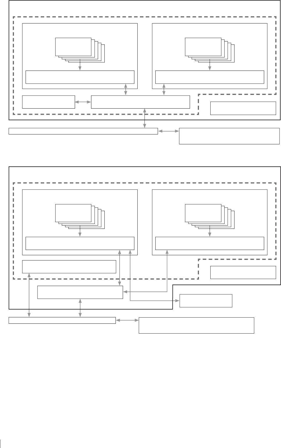
(When the optional access point is used)
DIGITAL RADIOGRAPHY DR-ID 1200
PANEL UNIT DR-ID 1200PU
Image processing unit of other
digital radiography system DR-ID 300CL
Hub
Battery charger
Power supply unit DR-ID 1200MP
Flat panel
sensor
Image processing unit DR-ID 300CL*1, *3
DOCKING UNIT DR-ID 1200DU
Docking stand DR-ID 1200DS
Flat panel
sensor
Access point
(When an access point installed in the hospital is used)
DIGITAL RADIOGRAPHY DR-ID 1200
PANEL UNIT DR-ID 1200PU
Hub
Battery charger
Power supply unit DR-ID 1200MP
Flat panel
sensor
Image processing unit DR-ID 300CL*3
DOCKING UNIT DR-ID 1200DU
Docking stand DR-ID 1200DS
Flat panel
sensor
Access point
Control cabinet DR-ID 1200MC*2
Image processing unit of other
digital radiography system DR-ID 300CL

vii
FDR D-EVO
II Operation Manual 897N120339A
7KHUHDUHIRXUW\SHVRIÀDWSDQHOVHQVRUV'5,'6('5,'6('5,'6(DQG
DR-ID 1212SE (wireless/wired communication mode). Although the contents of this manual are
GHVFULEHGE\WDNLQJWKHH[DPSOHRI'5,'6(WKHVDPHFDQDOVREHDSSOLHGWRRWKHUÀDWSDQHO
VHQVRUV:LWKUHJDUGWRWKHGHVFULSWLRQVSHFL¿FWRDFHUWDLQW\SHRIÀDWSDQHOVHQVRUWKHSURGXFW
name is given in the description.
The panel unit (DR-ID 1200PU) and the docking unit (DR-ID 1200DU) can be used simultaneously.
Up to two power supply units (DR-ID 1200MP) and up to three docking stands (DR-ID 1200DS) can
be used.
To use the digital radiography (DR-ID 1200), either one power supply unit or docking stand is
necessary.
*1 The software for the control cabinet is installed on the image processing unit (DR-ID 300CL).
'HSHQGLQJRQWKHFRQ¿JXUDWLRQWKHFRQWUROFDELQHW'5,'0&PD\QRWEHLQFOXGHGLQWKH
system.
If not included, the software for the control cabinet can be installed on the image processing unit
(DR-ID 300CL).
)RUGHWDLOVSHFL¿FDWLRQRILPDJHSURFHVVLQJXQLWSOHDVHUHIHUWR³'5,'&/2SHUDWLRQ
Manual”.
*3 When the image processing unit (DR-ID 300CL) is used in patient environment, run the notebook
computer on battery power.

viii FDR D-EVO
II Operation Manual 897N120339A

ix
FDR D-EVO
II Operation Manual 897N120339A
Contents at a Glance
Chapter 1For Safe Operation
This chapter presents Warnings and Cautions we wish you to observe for safe
operation of the FDR D-EVO II.
Chapter 26\VWHP&RQ¿JXUDWLRQ3URGXFW2YHUYLHZ
This chapter gives the various unit names and describes their functions and
features of the FDR D-EVO II.
Chapter 3Basic Operation
This chapter describes start-up, shut-down and other basic operations of the
FDR D-EVO II.
Chapter 4Troubleshooting
This chapter describes how to troubleshoot in the event of an error on the FDR
D-EVO II, and provides explanations about a list of error messages each of
which appears when an error occurs.
Chapter 5Daily Inspection and Maintenance
This chapter describes daily care and maintenance we wish you to perform so
that you can use the FDR D-EVO II optimally.
Appendix
$SSHQGL[$ 6SHFL¿FDWLRQV
Appendix Z Precautions for Exposure
Appendix O Use of Optional Items
Maintenance and Inspection
Radio frequency (RF) compliance information
xFDR D-EVO
II Operation Manual 897N120339A
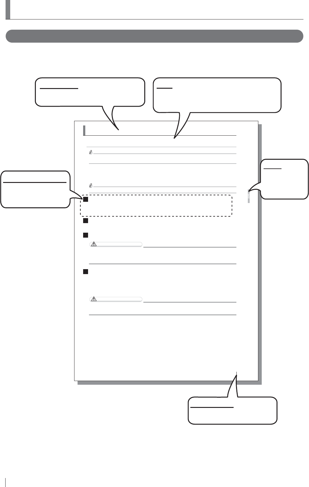
How to Read This Manual
%DVLFSDJHOD\RXW
3OHDVHKDYHDJRRGJUDVSRIWKHEDVLFSDJHFRQ¿JXUDWLRQRIWKLV2SHUDWLRQ0DQXDODVLOOXVWUDWHG
EHORZIRU\RXWRXVHLWPRUHHI¿FLHQWO\
3-9
Basic Operation
3
FDR D-EVO
II Operation Manual 897N120339A
3.2
Starting Up and Shutting Down the System
This section explains how to start up and shut down the system. Operations are required on the power
VXSSO\XQLWGRFNLQJVWDQGÀDWSDQHOVHQVRUDQGLPDJHSURFHVVLQJXQLW
The image processing unit in this section is only an example. For details on the image processing unit being used,
see the Operation Manual provided with the personal computer.
3.2.1 Starting Up the System
(When the DR-ID 1200PU is used)
Make sure that the power cable is connected to the image processing unit.
1 :KHQWKHÀDWSDQHOVHQVRULVXVHGLQZLUHOHVVFRPPXQLFDWLRQPRGHLQVWDOOWKHIXOO\FKDUJHG
EDWWHU\SDFNWRWKHÀDWSDQHOVHQVRU
:KHQLWLVXVHGLQZLUHGFRPPXQLFDWLRQPRGHFRQQHFWWKHÀDWSDQHOVHQVRUDQGWKHSRZHU
VXSSO\XQLWXVLQJWKH6(FDEOH
2 3UHVVWKH21VLGHRIWKHPDLQVZLWFKRIWKHSRZHUVXSSO\XQLW
Make sure that the power status LED is lit in blue.
3 :KHQWKHRSWLRQDODFFHVVSRLQWLVXVHGFRQQHFWWKHDFFHVVSRLQWWRWKHLPDJHSURFHVVLQJXQLW
CAUTIONS
8VHWKHRSWLRQDODFFHVVSRLQWE\FRQQHFWLQJLWWRWKHSUHVHWLPDJHSURFHVVLQJXQLWDQGWRWKH86%
FRQQHFWRU'RQRWXVHWKHRSWLRQDODFFHVVSRLQWE\FRQQHFWLQJLWWRRWKHULPDJHSURFHVVLQJXQLWDQG
RU86%FRQQHFWRU
4 3UHVVWKH21VLGHRIWKHPDLQVZLWFKRIWKHSRZHUVXSSO\XQLW
7KHLQLWLDOL]DWLRQSURFHVVVWDUWV
• All cables should be connected properly.
• No media should be inserted into the disk drive of image processing unit.
If the control cabinet is included in the system, the control cabinet starts up automatically.
CAUTIONS
,IWKHSRZHUVWDWXV/('RIWKHFRQWUROFDELQHWGRHVQRWFRPHRQDIWHUWXUQLQJRQWKHLPDJH
SURFHVVLQJXQLWWXUQRQWKHFRQWUROFDELQHW
3DJHQXPEHU
Displayed in conjunction with the
chapter number.
Section title
Shows the title of an operation procedure
described in the section.
Lead
Describes information we wish you to know in
advance of your operating the system or information
that may help you to operate it.
Operation procedure
Describes an operation
procedure according to
sequential numbers.
Index
A caption that
facilitates you to
open a desired
[Chapter] quickly.
xi
FDR D-EVO
II Operation Manual 897N120339A
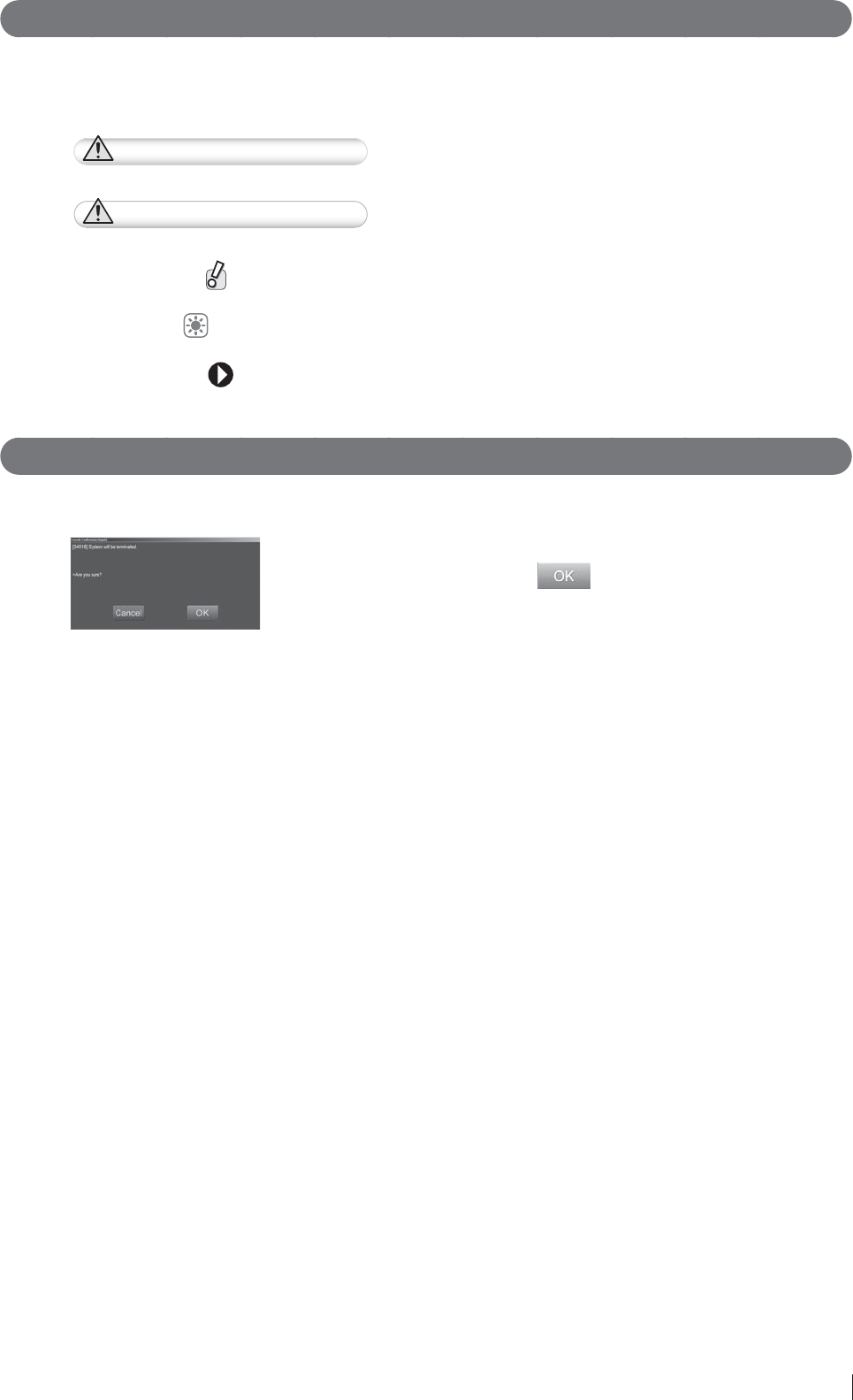
0DUNV
Information items to be observed when you are operating this system and the supplementary
remarks are described in this manual with the respective marks.
For the safe system operation, be sure to observe Warning/Caution.
WARNING Indicates hazardous situations that may lead to serious injuries or
even death if the precaution is not or cannot be followed.
CAUTIONS Indicates hazardous situations that may lead to mild or moderate
injury or physical damages if the caution is not or cannot be
followed.
Indicates procedures requiring special attention, instructions that
must be followed, supplementary explanations, etc.
HINT Shows an item helpful for further effective system operation.
Shows a more detailed operation method or an item that
describes additional information.
Expressions
Messages appear on the display panel and the buttons are shown as below.
Ɣ %XWWRQVH[DPSOH
------------------------------ Select .
The button to operate is shown.

xii FDR D-EVO
II Operation Manual 897N120339A
Contents
Introduction ...........................................................................................................................iii
FDR D-EVO II System Operation Manuals .......................................................................... v
Contents at a Glance ............................................................................................................ix
How to Read This Manual .................................................................................................... x
Chapter 1 For Safe Operation
1.1 Precautions Before Operating This Equipment .......................................................1-1
1.2 Precautions to be Observed When Using the Electric Medical Equipment ............. 1-2
1.3 Safety ......................................................................................................................1-3
1.4 Electromagnetic Compatibility (EMC) ....................................................................1-12
1.4.1
DR-ID 1200 ...................................................................................................................1-12
1.5 Precautions in Using the FDR D-EVO II ..............................................................1-17
1.5.1 Handling .................................................................................................................1-17
1.5.2 Before Exposure ....................................................................................................1-18
1.5.3 During Exposure ....................................................................................................1-19
1.5.4 During Cleaning .....................................................................................................1-20
1.5.5 Storage ..................................................................................................................1-20
1.5.6 Precautions Related to the Load Applied to the Flat Panel Sensor .......................1-21
1.5.7 Radio Waves .........................................................................................................1-22
1.5.8 Battery Pack Status Indicator ................................................................................1-23
1.6 Locations of Labels and Signs ..............................................................................1-24
1.6.1 Locations of Labels ................................................................................................1-24
1.6.2 DR-ID 1200 ............................................................................................................1-26
1.6.3 DR-ID 1200PU .......................................................................................................1-27
1.6.4 DR-ID 1200DU .......................................................................................................1-27
1.6.4 Safety and Other Symbols .....................................................................................1-28
1.6.5 Symboles de sécurité et autres .............................................................................1-29
1.7 Installation Conditions ...........................................................................................1-30
'H¿QLWLRQRI3DWLHQW(QYLURQPHQW ..........................................................................1-30
1.7.2 Installation Precautions ..........................................................................................1-31
1.7.3 Precautions for Installing the Access Point (Optional) ...........................................1-31
Chapter 2
6\VWHP&RQ¿JXUDWLRQ3URGXFW2YHUYLHZ
2.1 FDR D-EVO II .................................................................................................................................................. 2-1
6\VWHP&RQ¿JXUDWLRQ ..............................................................................................2-1
2.1.2 Features of the FDR D-EVO II .................................................................................................... 2-3
2.2 Unit Names and the Functions ................................................................................2-4
2.2.1 DR-ID 1200 ..............................................................................................................2-4
,PDJH3URFHVVLQJ8QLW'LVSOD\&RQ¿JXUDWLRQ .........................................................2-9
2.4 Routine Operation Diagram...................................................................................2-13
:LUHOHVV6SHFL¿FDWLRQV .........................................................................................2-14

xiii
FDR D-EVO
II Operation Manual 897N120339A
Chapter 3 Basic Operation
3.1 Preparing the Flat Panel Sensor .............................................................................3-1
3.1.1 Type of Flat Panel Sensor .......................................................................................3-1
3.1.2 Number of the Connectable Flat Panel Sensors .....................................................3-1
3.1.3 Connecting/Disconnecting the Flat Panel Sensor Connector ..................................3-1
3.1.4 Inserting/Removing the Flat Panel Sensor into/
from the Radiographic Examination Stand ..............................................................3-2
3.1.5 Changing the Direction of the Flat Panel Sensor Connector ...................................3-4
3.1.6 Charging the Battery Pack for the Flat Panel Sensor ..............................................3-5
3.1.7
Charging the Image Processing Unit ..............................................................................3-6
3.1.8 Installing/Removing the Battery Pack for the Flat Panel Sensor .............................3-6
3.1.10 Attaching the Flat Panel Sensor to the Docking Stand ............................................3-8
3.2
Starting Up and Shutting Down the System ...............................................................................3-9
3.2.1 Starting Up the System ............................................................................................3-9
3.2.2 Shutting Down the System .................................................................................... 3-11
3.3 Routine Operations ....................................................................................................3-13
Step 1 Entering the Patient Information .............................................................................3-14
Step 2 Selecting the Anatomical Region and Exposure/Study Menu .................................3-15
Step 3 X-ray Exposure .......................................................................................................3-17
[1] Positioning the patient ......................................................................................3-17
[2] X-ray exposure/Image displaying .....................................................................3-18
[3] Sleep mode .......................................................................................................3-19
[4] Extended Image Readout .................................................................................3-19
3.4 How to Use Memory Exposure Mode ........................................................................3-20
3.4.1 How to Start up and Use Memory Exposure Mode ...............................................3-20
3.4.2 How to Load Images ..............................................................................................3-21
3.4.3 List of Error Codes .................................................................................................3-22
3.4.4 How to Terminate Memory Exposure Mode ...........................................................3-22
&KDSWHU7URXEOHVKRRWLQJ
4.1
When a Message Appears on the Image Processing Unit .................................................... 4-1
[1] If a warning dialog box appears ......................................................................................4-1
[2] If the message dialogue box MD11001 appears ..............................................................4-1
[3] If an exposed image cannot be acquired .........................................................................4-2
[4] If the dialog box containing the error message numbered 13048 appears ......................4-3
[5]
If “Unusable due to error.” appears on the image processing unit ................................................4-3
[6] If any other message dialogue box appears ....................................................................4-4
4.2 How to Cope with an Error... ...................................................................................4-5
[1] When the image processing unit hangs up… ..................................................................4-5
[2] When the image processing unit is turned off due to an electrical outage .......................4-5
[3] If a hard disk of the image processing unit is damaged ...................................................4-6
[4] If a white image is displayed after an exposure ...............................................................4-6
[5] Precautions for operation when the device status is “Initializing” or
“Changing FPD” in the image processing unit’s “Output Device Status window” ............4-6
>@,IWKHÀDWSDQHOVHQVRUFDQQRWEHXVHGLQZLUHOHVVFRPPXQLFDWLRQPRGH ......................4-6
[7] If an error occurs on an output destination device ...........................................................4-7
Chapter 5 Daily Inspection and Maintenance
5.1
Daily User Inspection and Maintenance .................................................................... 5-1
5.1.1 Daily Inspection (DR-ID 1200) .................................................................................5-1
5.1.2 Periodical Inspection ................................................................................................5-2

xiv FDR D-EVO
II Operation Manual 897N120339A
$SSHQGL[$6SHFL¿FDWLRQV
$ 6SHFL¿FDWLRQV ..........................................................................................................A-1
A.1.1 Processing Capacity (DR-ID 1200) ......................................................................... A-1
A.1.2 Image Output (DR-ID 1200) .................................................................................... A-1
A.1.3 Reduced Equivalent ................................................................................................ A-2
A.1.4 Power Supply Conditions ........................................................................................ A-3
A.1.5 Environmental Conditions ....................................................................................... A-3
A.2 External View and Weight .......................................................................................A-5
A.2.1 DR-ID 1200 ............................................................................................................. A-5
A.3 Characteristics .........................................................................................................A-9
Appendix Z
Precautions for Exposure
Z.1
Precautions for Exposure in AUTO MODE ...........................................................................Z-1
Z.1.1 Radiation Field .........................................................................................................Z-1
Z.1.2 Depiction of the Cervical Region .............................................................................Z-2
Z.1.3 Depiction of the HIP JOINT AXL – 2 Menu ..............................................................Z-2
Z.1.4 EDR Image Data Analysis .......................................................................................Z-3
Z.2 Precautions for Exposure in SEMI-AUTO MODE ...................................................Z-4
Z.3 Precautions for Exposure in SEMI-X MODE ...........................................................Z-5
Z.4 Precautions for Exposure in FIX MODE ......................................................................Z-6
Z.5 Precautions for the Automatic X-ray Detection Function .............................................Z-7
Z.5.1 Precautions for Making an Exposure .......................................................................Z-7
Z.5.2 Precautions Related to the X-ray Exposure Time ....................................................Z-8
Z.6 Precautions for Use in Wireless Communication Mode ..............................................Z-9
Z.7 Other Precautions .................................................................................................Z-10
Z.7.1 Precautions for Exposure of a Subject in Relatively Large Contrast .....................Z-10
Z.7.2 Precautions for Flat Panel Sensor .........................................................................Z-10
Z.7.3 Precautions for Assuring the Radiation Field .........................................................Z-10
Z.7.4 Images Output When the X-ray Shot Switch is Operated Incorrectly ....................Z-10
Z.7.5 Precautions for Urgent Use ...................................................................................Z-11
Z.7.6 Precautions Related to Continuous Operation ......................................................Z-11
Z.7.7 Precautions Related to Grid ...................................................................................Z-11
Z.7.8 Precautions during Calibration ...............................................................................Z-11
Z.7.9 Precautions for Exposing the Flat Panel Sensor to X-ray ......................................Z-11
Z.7.10 Precautions for Extended Image Readout .............................................................Z-11
Z.7.10 Precautions for Using the Access Point ................................................................Z-12
Appendix O Use of Optional Items
O.1 Optional Items ....................................................................................................... O-1
O.2 Using the SE Storage Case ................................................................................... O-2
O.3 Using the Retaining Bracket for MP ....................................................................... O-3
O.4 DS Anchor Fixing Bracket ...................................................................................... O-4
O.5 Wall Fixing Bracket ................................................................................................. O-5
O.6 Access Point ........................................................................................................... O-6
Maintenance and Inspection
5DGLRIUHTXHQF\5)FRPSOLDQFHLQIRUPDWLRQ
Compliance with 1999/5/EC ................................................................................................. 3

1-1
For Safe Operation
1
FDR D-EVO
II Operation Manual 897N120339A
Chapter 1 For Safe Operation
3UHFDXWLRQV%HIRUH2SHUDWLQJ7KLV
(TXLSPHQW
Before using this equipment, please read “Precautions Before Operating This Equipment” carefully so
that you can operate it correctly.
Whenever you operate this equipment, be sure to observe those precautions. Failure to do so may
cause you to subject to injuries or property damage to occur.
The institution where the equipment is installed is responsible for its use and
maintenance.
In addition, this equipment should not be used by persons other than doctors or
suitably trained staff.
7KLVV\VWHPLVFODVVL¿HGDVDPHGLFDOGHYLFHXQGHU(&'LUHFWLYH((&
This equipment has been designed on the assumption that the patient would not
come into direct contact with it or for operation by appropriately trained operator.
Process waste correctly, as stipulated by local law or any regulations that apply.
Part of the components contains harmful substances which may pollute the ambient
environment if disposed carelessly. For details on product disposal, contact our
RI¿FLDOGHDOHURU)8-,),/05HSUHVHQWDWLYH

1-2
For Safe Operation
1
FDR D-EVO
II Operation Manual 897N120339A
1.2 Precautions to be Observed When
8VLQJWKH(OHFWULF0HGLFDO(TXLSPHQW
We ask that you observe these usage precautions and use the equipment correctly.
1. This equipment should be used only by people who have the proper skills.
2. Observe the following precautions when installing the equipment.
2-1. Install the equipment where water will not splash it.
2-2. Install the equipment where it will not be adversely affected by air pressure, temperature,
humidity, ventilation, sunlight, dust or the presence of salt, sulfur or like substances in the
atmosphere.
2-3. Make sure the equipment will remain in stable condition on a level surface and not be
subjected to vibration or shock.
2-4. Do not install the equipment in places where chemicals are stored or gases emitted.
2-5. Make sure that the power frequency, voltage and power consumption are appropriate.
2-6. Connect the ground wire correctly.
3. Observe the following precautions before beginning to use the device.
&RQ¿UPWKDWWKHJURXQGZLUHKDVEHHQFRPSOHWHO\FRQQHFWHG
3-2. Make sure that all cords have been connected properly and safely.
3-3. Be aware that correct diagnosis can be hindered and danger can result from using different
pieces of equipment together.
3-4. Make sure that the battery and power supply are installed properly.
4. Observe the following precautions when using the equipment.
4-1. Make sure not to exceed the time and dose required for diagnosis.
4-2. Always monitor the patient and the equipment for abnormalities.
4-3. Take an appropriate action, such as stopping the equipment after ensuring the patient’s
safety, if any abnormalities are found in his/her health or in the equipment.
5. Observe the following precautions after using the equipment.
5-1. Using the established procedure, then turn the power off.
5-2. When unplugging cords, do not pull on the body of the cord itself or apply unnecessary
force.
5-3. Observe the following precautions when storing the equipment.
I Store the equipment where water will not splash it.
II Store the equipment where it will not be adversely affected by air pressure, temperature,
humidity, ventilation, sunlight, dust or the presence of salt, sulfur or like substances in
the atmosphere.
III Make sure the equipment will remain in stable condition on a level surface and not be
subjected to vibration or shock.
IV Do not store the equipment in places where chemicals are stored or gases emitted.
5-4. After using the accessories, recollect them and put them back in order.
5-5. Make sure to clean the equipment for the next use.
,IWKHUHLVWURXEOHZLWKWKHHTXLSPHQWGRQRWDWWHPSWWR¿[LWUDQGRPO\,QVWHDGGRZKDWLV
indicated and entrust repairs to a professional.
7. Do not remodel the equipment.
8. Maintenance and Inspection
8-1. Make inspect the equipment and parts periodically.
8-2. If the equipment has not been used for a long time, make sure that it operates normally and
safely prior to using it again.
9. Other Items
9-1. When subjecting patients (particularly infants and pregnant women) to radiation, make sure
not to exceed the necessary time and dose. Also, ensure that radiation is contained within
WKHH[SRVXUHSODQHRIWKHÀDWSDQHOVHQVRU
9-2. Follow the Operation Manual and operate the equipment correctly.

1-3
For Safe Operation
1
FDR D-EVO
II Operation Manual 897N120339A
1.3 Safety
Before using the FDR D-EVO II, read this section thoroughly to ensure that you use the product
properly.
(OHFWULF6KRFN:DUQLQJVDQG&DXWLRQV
WARNING
The power supply to the FDR D-EVO II is AC100 to 240V.
7RDYRLGHOHFWULFVKRFNVXVHUVVKRXOGDOZD\VWDNHWKHIROORZLQJSUHFDXWLRQV
Ɣ 'RQRWRSHQDQ\FRYHUVZKHQLWLVQRWQHFHVVDU\
Ɣ ,QVWDOOWKHHTXLSPHQWLQDORFDWLRQZKHUHLWZLOOQRWEHH[SRVHGWRZDWHU
Ɣ 0DNHVXUHWKDWWKHJURXQGZLUHRIWKHHTXLSPHQWLVFRQQHFWHGFRPSOHWHO\
Ɣ &KHFNWKDWDOORIWKHFDEOHVDUHFRPSOHWHO\DQGVHFXUHO\FRQQHFWHG
Ɣ .HHSWKHFRQWUROFDELQHWRXWRIUHDFKRISDWLHQWV
WARNING
'RQRWWRXFKWKHSDWLHQW¶VERG\ZKLOHWRXFKLQJWKHFRQWUROFDELQHWDQGWKHLPDJHSURFHVVLQJ
XQLW2WKHUZLVHWKHSDWLHQWPD\UHFHLYHDQHOHFWULFVKRFN
WARNING
'RQRWXVHDPXOWLSOHWDSFRQQHFWRURUH[WHQVLRQFDEOHIRUSRZHULQJWKHGHYLFHVFRQVWLWXWLQJ
WKHV\VWHP2WKHUZLVH¿UHRUHOHFWULFVKRFNPD\RFFXUGXHWRWKHHOHFWULFDOORDGH[FHHGLQJWKH
allowable limit.
WARNING
2EVHUYHWKHIROORZLQJSUHFDXWLRQVZKHQXVLQJWKHFDEOHV
Ɣ 'RQRWWRXFKWKHSOXJDQGFRQQHFWRUZLWKZHWKDQGV2WKHUZLVHHOHFWULFVKRFNPD\UHVXOW
FDXVLQJGHDWKRUVHYHUHLQMXU\
Ɣ +ROGWKHSOXJRUFRQQHFWRUZKHQUHPRYLQJWKHFDEOH
3XOOLQJWKHFDEOHRUFDUU\LQJE\KROGLQJLWPD\GDPDJHWKHFDEOHFDXVLQJ¿UHRUHOHFWULFVKRFN
Ɣ 'RQRWGDPDJHRUUHPRGHOWKHFDEOH
'RQRWSODFHDKHDY\REMHFWRQWKHFDEOHRUOD\LWXQGHUWKHÀDWSDQHOVHQVRU'RQRWVWHSRQ
SXOOIRUFLEO\EHQGRUEXQGOHWKHFDEOH2WKHUZLVH¿UHRUHOHFWULFVKRFNPD\UHVXOW
WARNING
'RQRWWXUQRQWKHV\VWHPZLWKGHZFRQGHQVDWLRQRQWKHÀDWSDQHOVHQVRU2WKHUZLVH¿UHRU
HOHFWULFVKRFNPD\UHVXOW
WARNING
'RQRWXVHWKHHTXLSPHQWLQDORFDWLRQZKHUHPHWDOSDUWLFOHVFRXOGFRPHLQWRWKHHTXLSPHQW
7KLVPD\FDXVHDQHOHFWULFVKRFN
WARNING
'RQRWGLVDVVHPEOHRUUHPRGHOWKHHTXLSPHQW2WKHUZLVH¿UHRUHOHFWULFVKRFNPD\UHVXOW
.HHSDZD\IURPWKHSDUWVLQVLGHWKHSURGXFWZKLFKPD\FDXVHHOHFWULFVKRFN,I\RXWRXFK
them accidentally, death or severe injury may result.

1-4
For Safe Operation
1
FDR D-EVO
II Operation Manual 897N120339A
WARNING
'RQRWKLWRUGURSWKHHTXLSPHQWRUVXEMHFWLWWRVHYHUHVKRFN2WKHUZLVHWKHHTXLSPHQWPD\
EHGDPDJHG,IWKHGDPDJHGHTXLSPHQWLVXVHG¿UHRUHOHFWULFVKRFNPD\UHVXOW
,QDGGLWLRQGRQRWDSSO\VWURQJSUHVVXUHRQWRWKHÀDWSDQHOVHQVRU
,IDSSOLHGWKHÀDWSDQHOVHQVRUGHIRUPVDQGWKHZDWHUSURRIIXQFWLRQPD\EHFRPSURPLVHG
WARNING/AVERTISSEMENT
'RQRWXVHWKHÀDWSDQHOVHQVRUZLWKRXWWKHEDWWHU\SDFNV,IWKHEDWWHU\SDFNVDUHQRW
DWWDFKHGDQHOHFWULFVKRFNPD\UHVXOW
N’utilisez pas le détecteur à panneau plat sans les batteries. Si les batteries ne sont pas
FRQQHFWpHVXQFKRFpOHFWULTXHULVTXHGHVHSURGXLUH
WARNING
0DNHVXUHWRXVHWKHRSWLRQDOSDUWVDQGDFFHVVRULHVUHFRPPHQGHGE\XV)DLOXUHWRXVHWKH
RSWLRQDOSDUWVDQGDFFHVVRULHVUHFRPPHQGHGE\XVPD\UHVXOWLQGDPDJHWRWKHHTXLSPHQW
DQGRUHOHFWULFVKRFNDQGLQMXU\
CAUTIONS
$VWKHFDEOHVRIWKHHTXLSPHQWDUHORQJEHFDUHIXOQRWWRHQWDQJOHWKHFDEOHVGXULQJXVH
Also, be careful not to trip over the cables. Falls could result in injury.
CAUTIONS
)ROORZWKHVSHFL¿HGSURFHGXUHZKHQWXUQLQJRIIWKHHTXLSPHQW2WKHUZLVHWKHÀDWSDQHO
VHQVRUFRXOGEHGDPDJHGE\WKHUPDOVKRFN
CAUTIONS
'RQRWVWRUHPDJQHWLFPHGLDQHDUWKH'5V\VWHPDQGFRQWUROFDELQHW2WKHUZLVHPDJQHWLVP
JHQHUDWHGE\WKHHTXLSPHQWPD\FDXVHWKHGDWDWREHORVW
CAUTIONS
.HHSWKHHTXLSPHQWDZD\IURPSDWLHQW¶VERG\ÀXLGVFKHPLFDOVZDWHUHWF
2WKHUZLVHLWPD\EHFRPHGDPDJHGFDXVLQJ¿UHRUHOHFWULFVKRFN
,IQHFHVVDU\SURWHFWWKHÀDWSDQHOVHQVRUE\FRYHULQJLWZLWKDGLVSRVDEOHEDJ
([SORVLRQ:DUQLQJV
WARNING
%HFDXVHWKLVHTXLSPHQWLVQRWH[SORVLRQSURRIGRQRWXVHFRPEXVWLEOHDQGH[SORVLYHJDVHV
QHDUWKHHTXLSPHQW
WARNING
)ODPPDEOHJDVVHVPD\VWD\LQWKHURRPDIWHUGLVLQIHFWLRQ,I\RXWXUQWKHV\VWHPRQMXVWDIWHU
GLVLQIHFWLRQHQVXUHWKDWWKHURRPLVZHOOYHQWLODWHGEHIRUHSRZHULQJRQWKHV\VWHP

1-5
For Safe Operation
1
FDR D-EVO
II Operation Manual 897N120339A
:DUQLQJVIRU$EQRUPDOLWLHV
WARNING
,IDQ\RIWKHIROORZLQJRFFXUVLPPHGLDWHO\WXUQRIIWKHSRZHURIHDFKXQLWXQSOXJWKHSRZHU
FDEOHIURPWKHRXWOHWDQGWKHQFRQWDFWRXURI¿FLDOGHDOHURU)8-,),/05HSUHVHQWDWLYH
Ɣ :KHQVPRNHVWUDQJHRGRURUDEQRUPDOVRXQGLVSUHVHQW
Ɣ :KHQDIRUHLJQREMHFWVXFKDVDPHWDOREMHFWRUOLTXLGHQWHUVWKHSURGXFW
Ɣ :KHQWKHHTXLSPHQWLVGURSSHGRUKLWDQGLVGDPDJHG
Avertissements relatifs aux anomalies
AVERTISSEMENT
6LO¶XQHGHVFRQGLWLRQVUpSHUWRULpHVFLDSUqVVHSURGXLWPHWWH]LPPpGLDWHPHQWFKDTXHXQLWp
hors tension, débranchez le cordon d’alimentation de la prise secteur, puis contactez notre
UHYHQGHXUDJUppRXQRWUHUHSUpVHQWDQW)8-,),/0
Ɣ (QFDVGHSUpVHQFHGHIXPpHG¶XQHRGHXUpWUDQJHRXG¶XQEUXLWDQRUPDO
Ɣ (QFDVGHSpQpWUDWLRQG¶XQFRUSVpWUDQJHUFRPPHXQREMHWPpWDOOLTXHRXG¶XQOLTXLGHGDQV
le produit.
Ɣ (QFDVG¶HQGRPPDJHPHQWGHO¶pTXLSHPHQWVXLWHjXQHFKXWHRXjXQLPSDFW
Installation Precautions
CAUTIONS
'RQRWLQVWDOOWKHV\VWHPLQDORFDWLRQZLWKWKHIROORZLQJFRQGLWLRQV
Ɣ :KHUHWKHWHPSHUDWXUHFKDQJHVVKDUSO\
Ɣ &ORVHWRKHDWVRXUFHVVXFKDVDKHDWHU
Ɣ :KHUHWKHV\VWHPPD\EHH[SRVHGWRZDWHUGXHWRZDWHUOHDNDJHRULQJUHVV
Ɣ :KHUHFRUURVLYHJDVPD\EHJHQHUDWHG
Ɣ :KHUHWKHUHLVH[FHVVLYHGXVW
Ɣ :KHUHWKHV\VWHPLVVXEMHFWWRIUHTXHQWRUH[FHVVLYHYLEUDWLRQVKRFN
Ɣ :KHUHWKHV\VWHPLVH[SRVHGWRGLUHFWVXQOLJKW
Ɣ :KHUHWKHUHLVQRYHQWLODWRU
CAUTIONS
8VHWKHHTXLSPHQWRQDÀDWSODFH,IWKHHTXLSPHQWIDOOVLWPD\FDXVHGDPDJHWRWKHHTXLSPHQW
or personal injury.
CAUTIONS
:KHQ\RXPRYHWKHHTXLSPHQWSODFHLWLQWKHFDVVHWWHVWRUDJHER[RIDPRELOH;UD\XQLWRUKROG
LWE\KDQGWRSUHYHQWLWIURPIDOOLQJ,IWKHFDUWLVXVHGWRPRYHWKHHTXLSPHQWSODFHLWKRUL]RQWDOO\
CAUTIONS
)RUYHWHULQDU\RUPRELOHDSSOLFDWLRQVSOHDVHFRQWDFWRXURI¿FLDOGHDOHURU)8-,),/0
Representative.
CAUTIONS
:KHQWKHGHYLFHVDUHXVHGRXWGRRUVLQZLUHOHVVFRPPXQLFDWLRQPRGHFRQWDFWRXURI¿FLDO
dealer or FUJIFILM Representative.

1-6
For Safe Operation
1
FDR D-EVO
II Operation Manual 897N120339A
CAUTIONS/ATTENTION
Do not place any object in a place where removal of the power cable is prevented.
1HSODFH]DXFXQREMHWjXQHPSODFHPHQWJrQDQWOHGpEUDQFKHPHQWGXFkEOHG¶DOLPHQWDWLRQ
CAUTIONS
7RHQVXUHRSWLPDOLPDJHTXDOLW\LWLVUHFRPPHQGHGWKDW\RXGRQRWXVHWKHÀDWSDQHOVHQVRU
QHDUGHYLFHVPRWRUWUDQVIRUPHUVZLWFKLQJVXSSO\HWFWKDWJHQHUDWHHOHFWURPDJQHWLFQRLVH
CAUTIONS
7RHQVXUHRSWLPDOLPDJHTXDOLW\LWLVUHFRPPHQGHGWKDW\RXGRQRWSODFHWKHFDEOHVSRZHU
FDEOHFRPPXQLFDWLRQFDEOHHWFRIWKHHTXLSPHQWQHDUGHYLFHVPRWRUWUDQVIRUPHUVZLWFKLQJ
VXSSO\HWFWKDWJHQHUDWHHOHFWURPDJQHWLFQRLVHDQGWKHLUFDEOHV
CAUTIONS
Do not install the power supply unit in a place where it may be contacted inadvertently. In
DGGLWLRQWDNHFDUHQRWWRPDNHFRQWDFWZLWKWKHSRZHUVXSSO\XQLWH[FHSWZKHQRSHUDWLQJWKH
main switch. If the fan inside the power supply unit malfunctions, the power supply unit may
EHFRPHKRWFDXVLQJLQMXU\
Connection Instructions
WARNING
0DNHVXUHWKDWWKHGHYLFHVWREHFRQQHFWHGWRWKHHTXLSPHQWDUHDXWKRUL]HGIRUFRQQHFWLRQ
WARNING
&RQQHFWWKHSDQHOXQLW'5,'38DQGWKHGRFNLQJXQLW'5,''8RQO\WRWKHDFFHVV
SRLQWLPDJHSURFHVVLQJXQLWRUWKHFRQWUROFDELQHW
3UHFDXWLRQVRQ([WHUQDO1HWZRUN&RQQHFWLRQ
CAUTIONS
:KHQDVHWWLQJRIWKHQHWZRUNWRZKLFKWKHHTXLSPHQWLVFRQQHFWHGKDVEHHQFKDQJHG
FKHFNWKDWWKHFKDQJHGRHVQRWDIIHFWWKHV\VWHPRSHUDWLRQDQGWDNHPHDVXUHVLIQHFHVVDU\
7KHVHWWLQJFKDQJHPD\LQFOXGHWKHIROORZLQJ
Ɣ &KDQJHRIFRQQHFWLRQGHVWLQDWLRQ
Ɣ $GGLWLRQRIGHYLFHV
Ɣ 5HPRYDORIGHYLFHV
Ɣ 8SGDWHRIGHYLFHV
Ɣ 8SJUDGHRIGHYLFHV

1-7
For Safe Operation
1
FDR D-EVO
II Operation Manual 897N120339A
:DUQLQJVDQG&DXWLRQVRQ1HWZRUN
WARNING
0DNHVXUHWRXVHWKHRSWLRQDOSDUWVDFFHVVRULHVDQGQHWZRUNVUHFRPPHQGHGE\XV)DLOXUHWR
XVHWKHRSWLRQDOSDUWVDFFHVVRULHVDQGQHWZRUNVUHFRPPHQGHGE\XVPD\UHVXOWLQGDPDJHWR
WKHHTXLSPHQWDQGRUHOHFWULFVKRFNDQGLQMXU\
CAUTIONS
&RQQHFWWRWKH(WKHUQHW1HWZRUNRI%$6(7;RU%$6(7SUHVFULEHGLQWKH,(((VWDQGDUG
'RQRWFRQQHFWWHOHSKRQHOLQHVWR/$1FRQQHFWRU2QO\873W\SHVWUDLJKW/$1FDEOHVRISDLU
&DWHJRU\FDEOH&$7(RUKLJKHUDUHDSSURSULDWHIRUFRQQHFWLRQWRWKLVFRQQHFWRU
CAUTIONS
$IWHUFRQQHFWLQJWKLVV\VWHPWRWKHQHWZRUNZLWKRWKHUV\VWHPVFRQ¿UPWKDWWKHRWKHUV\VWHPV
DUHQRWDIIHFWHG,IWKH\DUHDIIHFWHGWDNHFRXQWHUPHDVXUHVVXFKDVQHWZRUNVHSDUDWLRQ
System Isolation Instructions
WARNING
To ensure complete system isolation, never install any unauthorized accessories or other such
items.
:KHQLWLVQHFHVVDU\WRLQVWDOODXWKRUL]HGDFFHVVRULHVRURSWLRQDOLWHPVFRQWDFWRXURI¿FLDO
dealer or FUJIFILM Representative.
WARNING
.HHSHTXLSPHQWRWKHUWKDQWKRVHXVHGIRUSDWLHQWVRXWRIWKHLUUHDFKWRHQVXUHDSSURSULDWH
system isolation.
WARNING
,QQRUPDOXVHKDYHDSDWLHQWWDNHDSURSHUSRVLWLRQLQJIRUH[SRVXUH7KHRSHUDWRUVKRXOG
operate the system in a place where safety from radiation is ensured. The operator should
DOVRPDNHVXUHEHIRUHH[SRVXUHWKDWQRRQHEXWWKHSDWLHQWLVLQWKHH[SRVXUHDUHDDQGWKH
RSHUDWLQJDUHDRIWKHV\VWHP
Software Precautions
CAUTIONS
Do not install additional software to the system. Do not uninstall any of the software
preinstalled in the system.
The system is preinstalled with the appropriate software. If other software is installed or if the
H[LVWLQJVRIWZDUHLVXQLQVWDOOHGYDULRXVRSHUDWLRQDOHUURUVPD\UHVXOW

1-8
For Safe Operation
1
FDR D-EVO
II Operation Manual 897N120339A
Disinfection Instructions
WARNING
&RQ¿UPWKDWWKHUHVSLUDWRU\GHQVLW\RIGLVLQIHFWDQWLQFOXGLQJVROYHQWLVXQGHUOHJDOUHJXODWLRQ
&HUWDLQGLVLQIHFWDQWVPD\GDPDJHKHDOWK:KHQXVLQJDGLVLQIHFWDQWIROORZLQVWUXFWLRQV
supplied by the manufacturers.
WARNING
'RQRWXVHWKHIROORZLQJGLVLQIHFWDQWVRUVWHULOL]HUVDWWKHWLPHRIGLVLQIHFWLRQ4XDOLW\
SHUIRUPDQFHDQGVDIHW\RIWKHHTXLSPHQWFDQQRWEHDVVXUHG
Ɣ &KORULFGLVLQIHFWDQWZKLFKLVVWURQJO\FRUURVLYHWRPHWDOVDQGUXEEHUSDUWV
Ɣ 'LVLQIHFWDQWZKRVHXVHVRQPHWDOVSODVWLFVDQGFRDWLQJDUHIRUELGGHQDFFRUGLQJWRWKH
instructions supplied with the disinfectant.
Ɣ )RUPDOLQJDVDQGGLVLQIHFWDQWVSUD\VWKDWPD\JHWLQVLGHWKHHTXLSPHQW
Ɣ 8OWUDYLROHWVWHULOL]HUV
Disinfectant ethanol is recommended for disinfection. Carefully read the instructions and
cautions supplied with the disinfectant before use.
For details on the disinfectant, contact a FUJIFILM dealer or the service representatives at the
DJHQF\IURPZKLFK\RXSXUFKDVHGWKHGLVLQIHFWDQW
CAUTIONS
,IÀDWSDQHOVHQVRULVQRWGLVLQIHFWHGLWPD\OHDGVHFRQGDU\LQIHFWLRQ
Be sure to disinfect with ethanol after use.
CAUTIONS
&OHDQWKHVHQVRUXQLWRIWKHÀDWSDQHOVHQVRUZLWKHWKDQROIRUGLVLQIHFWLRQHWFIRUHDFKSDWLHQW
to prevent infection.
3UHFDXWLRQVIRU&KDUJLQJWKH%DWWHU\3DFN
CAUTIONS
2EVHUYHWKHIROORZLQJSUHFDXWLRQVZKHQFKDUJLQJWKHEDWWHU\SDFNRSWLRQDOXVLQJWKHEDWWHU\
FKDUJHURSWLRQDO
Ɣ 'RQRWXVHWKHEDWWHU\SDFN<RUEDWWHU\FKDUJHULQFRPELQDWLRQZLWKDQ\EDWWHU\
SDFNRUEDWWHU\FKDUJHULQFOXGLQJWKHSRZHUFDEOHRWKHUWKDQWKRVHUHFRPPHQGHGE\
FUJIFILM Corporation.
Ɣ 'RQRWGLVDVVHPEOHRUFRQYHUWWKHEDWWHU\SDFNRUEDWWHU\FKDUJHU
Ɣ ,IWKHEDWWHU\SDFNRUEDWWHU\FKDUJHUEHFRPHVIDXOW\FRQVXOWRXURI¿FLDOGHDOHURU)8-,),/0
Representative.
Ɣ 'RQRWFRYHUWKHKROHVLQWKHEDWWHU\FKDUJHUZLWKIRUHLJQPDWWHU
Ɣ $YRLGWKHDFFXPXODWLRQRIGXVWRQWKHEDWWHU\FKDUJHU
Ɣ ,QVHUWWKHEDWWHU\SDFNLQWRWKHEDWWHU\FKDUJHUVHFXUHO\
Ɣ ,IWKHLQVHUWLRQGLUHFWLRQRUSRVLWLRQRIWKHEDWWHU\SDFNLVLQFRUUHFWWKHEDWWHU\SDFNLVQRW
FKDUJHGSURSHUO\
Ɣ :KHQLQVHUWLQJWKHEDWWHU\SDFNSUHYHQWIRUHLJQPDWWHUIURPJHWWLQJLQWRWKHEDWWHU\FKDUJHU
Ɣ :KLOHFKDUJLQJWKHEDWWHU\SDFNGRQRWDOORZWKHEDWWHU\SDFNRUEDWWHU\FKDUJHUJHWZHWRU
dusty.
Ɣ 'RQRWVWHSRQWKH$&DGDSWHURIWKHEDWWHU\FKDUJHU$OVREHFDUHIXOQRWWRWULSRYHUWKH
power cable.
Ɣ 'RQRWVXEMHFWWKHEDWWHU\SDFNDQGEDWWHU\FKDUJHUWRVHYHUHVKRFNE\GURSSLQJWKHPHWF
Ɣ 'RQRWSODFHWKHEDWWHU\FKDUJHUZLWKLQWKHUHDFKRISDWLHQWV

1-9
For Safe Operation
1
FDR D-EVO
II Operation Manual 897N120339A
Ɣ 'RQRWFKDUJHWKHEDWWHU\SDFNQHDU¿UHRUXQGHUVWURQJVXQVKLQH,IWKHEXLOWLQSURWHFWLRQ
PHFKDQLVPVDUHDFWLYDWHGE\DKLJKWHPSHUDWXUHWKHEDWWHU\SDFNFDQQRWEHFKDUJHG$OVR
LIWKHEXLOWLQSURWHFWLRQPHFKDQLVPVDUHGDPDJHGWKHEDWWHU\SDFNPD\EHFKDUJHGZLWK
H[WUHPHO\KLJKFXUUHQWDQGYROWDJHDQGDEQRUPDOFKHPLFDOUHDFWLRQVPD\RFFXULQVLGHWKH
EDWWHU\SDFNFDXVLQJLWWRRYHUKHDWHPLWVPRNHH[SORGHRULJQLWH
Ɣ 7RFKDUJHWKHEDWWHU\SDFNEHVXUHWRXVHWKHGHVLJQDWHGEDWWHU\FKDUJHUDQGWRREVHUYH
WKHFKDUJLQJFRQGLWLRQVVSHFL¿HGE\)8-,),/0&RUSRUDWLRQ,IWKHEDWWHU\SDFNLVFKDUJHGLQ
RWKHUFRQGLWLRQVWHPSHUDWXUHRUYROWDJHFXUUHQWKLJKHUWKDQVSHFL¿HGUHPRGHOHGEDWWHU\
FKDUJHUHWFWKHEDWWHU\SDFNPD\EHRYHUFKDUJHGRUFKDUJHGZLWKH[WUHPHO\KLJKFXUUHQW
DQGDEQRUPDOFKHPLFDOUHDFWLRQVPD\RFFXULQVLGHWKHEDWWHU\SDFNFDXVLQJLWWRRYHUKHDW
HPLWVPRNHH[SORGHRULJQLWH
Ɣ ,PPHGLDWHO\VWRSFKDUJLQJWKHEDWWHU\SDFNLIFKDUJLQJLVQRWFRPSOHWHGZLWKLQWKHVSHFL¿HG
WLPH2WKHUZLVHWKHEDWWHU\SDFNPD\RYHUKHDWHPLWVPRNHH[SORGHRULJQLWH
Ɣ 'RQRWXVHWKHÀDWSDQHOVHQVRUQHDUWKHSRZHUFDEOH
Ɣ 'RQRWXVHDIDXOW\RUEURNHQEDWWHU\FKDUJHURU$&DGDSWHU
Ɣ 1RWHWKDWWKHÀDWSDQHOVHQVRUFDQQRWEHFKDUJHGE\XVLQJWKH6(FRPPXQLFDWLRQFDEOHWKDW
FRQQHFWVWKHÀDWSDQHOVHQVRUDQGWKHDFFHVVSRLQWRSWLRQDO
%DWWHU\3DFN,QVWUXFWLRQV
WARNING
Ɣ %DWWHU\SDFNUHTXLUHVUHJXODUFKHFNXSDQGUHSODFHPHQW%DWWHU\FDSDFLW\EHJLQVWRZDQH
after a period of time.
Ɣ ,IWKLVHTXLSPHQWLVQRWLQXVHIRUZKLOHVWRUHLWZLWKWKHEDWWHU\SDFNUHPRYHG
1RWUHPRYLQJWKHEDWWHU\SDFNPD\FDXVHPDOIXQFWLRQ
CAUTIONS
2EVHUYHWKHIROORZLQJSUHFDXWLRQVZKHQXVLQJWKHEDWWHU\SDFNRSWLRQDO
Ɣ 7KHEDWWHU\SDFN1LVXVHGZLWKWKHÀDWSDQHOVHQVRU'RQRWXVHWKHPLQRWKHU
combinations.
Ɣ &KDUJHWKHEDWWHU\SDFNRQO\ZLWKWKHGHVLJQDWHGEDWWHU\FKDUJHU,IWKHEDWWHU\SDFNLV
FKDUJHGXQGHUWKHFKDUJLQJFRQGLWLRQVYROWDJHFXUUHQWDQGFKDUJLQJPHWKRGGLIIHUHQW
IURPWKRVHVSHFL¿HGE\)8-,),/0&RUSRUDWLRQWKHEDWWHU\SDFNPD\HPLWVPRNHLJQLWH
H[SORGHRUOHDNÀXLG
Ɣ 6WRUHWKHEDWWHU\SDFNLQDFRRODQGGDUNSODFH5HFKDUJHWKHVWRUHGEDWWHU\SDFNHYHU\VL[
months or every year. Otherwise a decrease in battery capacity or other problems may result.
Ɣ 'RQRWOHDYHWKHUHPRYHGEDWWHU\SDFNLQWKHFDURURWKHUSODFHVH[SRVHGWRKLJK
WHPSHUDWXUH,IWKHEDWWHU\SDFNLVXVHGRUVWRUHGLQDSODFHZKHUHLWLVH[SRVHGWRKLJK
WHPSHUDWXUHWKHEDWWHU\SDFNPD\HPLWVPRNHLJQLWHH[SORGHRUOHDNÀXLG
Ɣ 8VHRUVWRUHWKHEDWWHU\SDFNRQO\LQWKHHQYLURQPHQWDOFRQGLWLRQVVSHFL¿HGE\)8-,),/0
&RUSRUDWLRQ,IWKHEDWWHU\SDFNLVXVHGRUVWRUHGLQDSODFHZKHUHLWLVH[SRVHGWRKLJK
WHPSHUDWXUHWKHEDWWHU\SDFNPD\HPLWVPRNHLJQLWHH[SORGHRUOHDNÀXLG
Ɣ :KHQGLVSRVLQJRIWKHEDWWHU\SDFNFRQVXOWRXURI¿FLDOGHDOHURU)8-,),/05HSUHVHQWDWLYH
Ɣ 'RQRWGLVDVVHPEOHRUUHPRGHOWKHEDWWHU\SDFN7KHEDWWHU\SDFNLVHTXLSSHGZLWKEXLOWLQ
VDIHW\DQGSURWHFWLRQPHFKDQLVPV,IWKH\DUHGDPDJHGWKHEDWWHU\SDFNPD\RYHUKHDWHPLW
VPRNHH[SORGHRULJQLWH
Ɣ %HFDUHIXOQRWWRGURSWKHEDWWHU\SDFN7KHSDWLHQWPD\EHLQMXUHG
Ɣ 'RQRWWRXFKWKHWHUPLQDORIWKHEDWWHU\SDFNGLUHFWO\7KHUHLVDULVNRIHOHFWULFVKRFN
Ɣ 'RQRWFRQQHFWWKHSRVLWLYHDQGQHJDWLYHWHUPLQDOVZLWKDZLUHRUDQ\PHWDOREMHFW
'RQRWFDUU\RUVWRUHWKHEDWWHU\SDFNWRJHWKHUZLWKPHWDOREMHFWVVXFKDVQHFNODFHVRU
KDLUSLQV2WKHUZLVHWKHEDWWHU\SDFNPD\VKRUWFLUFXLWDQGRYHUFXUUHQWPD\ÀRZFDXVLQJ
WKHEDWWHU\SDFNWRRYHUKHDWHPLWVPRNHH[SORGHRULJQLWH0HWDOREMHFWVVXFKDVQHFNODFHV
or hairpins may also become hot.
Ɣ 'RQRWWKURZWKHEDWWHU\SDFNLQWR¿UHRUH[SRVHLWWRH[FHVVLYHKHDW2WKHUZLVHLWVLQVXODWRU
PD\PHOWLWVJDVUHOHDVHYHQWRUVDIHW\PHFKDQLVPVPD\EHGDPDJHGDQGRULWVHOHFWURO\WH
PD\FDWFK¿UHFDXVLQJWKHEDWWHU\SDFNWRRYHUKHDWHPLWVPRNHH[SORGHRULJQLWH
Ɣ 'RQRWXVHRUOHDYHWKHEDWWHU\SDFNLQDSODFHZKHUHLWLVH[SRVHGWRKLJKWHPSHUDWXUH&
RUKLJKHUVXFKDV¿UHRUDKHDWHU,IWKHUHVLQVHSDUDWRULVGDPDJHGGXHWRKHDWWKHEDWWHU\
SDFNPD\VKRUWFLUFXLWFDXVLQJLWWRRYHUKHDWHPLWVPRNHH[SORGHRULJQLWH

1-10
For Safe Operation
1
FDR D-EVO
II Operation Manual 897N120339A
Ɣ 'RQRWLPPHUVHWKHEDWWHU\SDFNLQZDWHURUVHDZDWHUDQGGRQRWDOORZLWWREHFRPHZHW
,IWKHEXLOWLQSURWHFWLRQPHFKDQLVPVDUHGDPDJHGWKHEDWWHU\SDFNPD\RYHUKHDWHPLW
VPRNHH[SORGHRULJQLWH
Ɣ 'RQRWSLHUFHWKHEDWWHU\SDFNZLWKDQDLOKLWLWZLWKDKDPPHURUVWHSRQLW2WKHUZLVHWKH
EDWWHU\SDFNPD\EHGDPDJHGRUGHIRUPHGDQGVKRUWFLUFXLWFDXVLQJLWWRRYHUKHDWHPLW
VPRNHH[SORGHRULJQLWH
Ɣ 'RQRWVXEMHFWWKHEDWWHU\SDFNWRVWURQJLPSDFWRUWKURZLW,IWKHEXLOWLQSURWHFWLRQ
PHFKDQLVPVDUHGDPDJHGWKHEDWWHU\SDFNPD\EHFKDUJHGZLWKH[WUHPHO\KLJKFXUUHQWDQG
YROWDJHDQGDEQRUPDOFKHPLFDOUHDFWLRQVPD\RFFXULQVLGHWKHEDWWHU\SDFNFDXVLQJLWWR
RYHUKHDWHPLWVPRNHH[SORGHRULJQLWH
Ɣ 'RQRWXVHDQDSSDUHQWO\GDPDJHGRUGHIRUPHGEDWWHU\SDFN2WKHUZLVHWKHEDWWHU\SDFN
PD\RYHUKHDWHPLWVPRNHH[SORGHRULJQLWH
Ɣ 'RQRWVROGHUWKHEDWWHU\SDFNGLUHFWO\2WKHUZLVHLWVLQVXODWRUPD\PHOWRULWVJDVUHOHDVH
YHQWRUVDIHW\PHFKDQLVPVPD\EHGDPDJHGFDXVLQJWKHEDWWHU\SDFNWRRYHUKHDWHPLW
VPRNHH[SORGHRULJQLWH
Ɣ 'RQRWUHYHUVHWKHSRVLWLYHDQGQHJDWLYHWHUPLQDOV2WKHUZLVHWKHEDWWHU\SDFNPD\
EHUHYHUVHFKDUJHGGXULQJFKDUJLQJ$VDUHVXOWDEQRUPDOFKHPLFDOUHDFWLRQVPD\RFFXU
LQVLGHWKHEDWWHU\SDFNRUH[WUHPHO\KLJKFXUUHQWPD\ÀRZGXULQJGLVFKDUJLQJFDXVLQJLWWR
RYHUKHDWHPLWVPRNHH[SORGHRULJQLWH
Ɣ 7KHEDWWHU\SDFNKDVDSUHGHWHUPLQHGSRODULW\,I\RXFDQQRWFRQQHFWWKHEDWWHU\SDFNWRWKH
EDWWHU\FKDUJHURURWKHUHTXLSPHQWGRQRWFRQQHFWWKHEDWWHU\SDFNIRUFHIXOO\0DNHVXUH
WKDWWKHWHUPLQDOVDUHFRUUHFWO\RULHQWHG,IWKHEDWWHU\SDFNLVFRQQHFWHGLQUHYHUVHLWZLOO
EHUHYHUVHFKDUJHGDQGDEQRUPDOFKHPLFDOUHDFWLRQVPD\RFFXULQVLGHWKHEDWWHU\SDFN
FDXVLQJLWWRRYHUKHDWHPLWVPRNHH[SORGHRULJQLWH
Ɣ 'RQRWFRQQHFWWKHEDWWHU\SDFNWRDQHOHFWULFDORXWOHWRUFLJDUHWWHOLJKWHUVRFNHWLQDFDU
2YHUFXUUHQWPD\ÀRZWRWKHEDWWHU\SDFNGXHWRKLJKYROWDJHDSSOLHGFDXVLQJWKHEDWWHU\
SDFNWRRYHUKHDWHPLWVPRNHH[SORGHRULJQLWH
Ɣ 'RQRWXVHWKHEDWWHU\SDFNIRUHTXLSPHQWRWKHUWKDQWKRVHVSHFL¿HG2WKHUZLVHWKH
JXDUDQWHHGSHUIRUPDQFHZLOOEHUHGXFHGDQGRUWKHVHUYLFHOLIHZLOOEHVKRUWHQHG'HSHQGLQJ
RQWKHHTXLSPHQWWRZKLFKWKHEDWWHU\SDFNLVFRQQHFWHGH[WUHPHO\KLJKFXUUHQWPD\ÀRZ
FDXVLQJWKHEDWWHU\SDFNWREHGDPDJHGRYHUKHDWHPLWVPRNHH[SORGHRULJQLWH
Ɣ ,IWKHHOHFWURO\WHOHDNHGIURPWKHEDWWHU\SDFNHQWHUVWKHH\HVGRQRWUXEWKHP:DVKWKH
eyes immediately with clean water such as tap water, and consult a doctor. Otherwise, eye
injury may result.
Ɣ 'RQRWXVHWKHEDWWHU\SDFNLQFRPELQDWLRQZLWKDSULPDU\EDWWHU\VXFKDVDGU\EDWWHU\RU
RWKHUEDWWHU\RIDGLIIHUHQWFDSDFLW\W\SHDQGRUEUDQG2WKHUZLVHWKHEDWWHU\SDFNPD\
EHRYHUFKDUJHGGXULQJFKDUJLQJDQGDEQRUPDOFKHPLFDOUHDFWLRQVPD\RFFXULQVLGHWKH
EDWWHU\SDFNFDXVLQJLWWRRYHUKHDWHPLWVPRNHH[SORGHRULJQLWH
Ɣ 'RQRWSXWWKHEDWWHU\SDFNLQDPLFURZDYHRYHQRUKLJKSUHVVXUHFRQWDLQHU2WKHUZLVHWKH
EDWWHU\SDFNPD\EHUDSLGO\KHDWHGRUGDPDJHGFDXVLQJLWWRRYHUKHDWHPLWVPRNHH[SORGH
RULJQLWH
Ɣ ,IWKHEDWWHU\SDFNOHDNVRUHPLWVDQXQXVXDORGRUUHPRYHLWIURP¿UHLPPHGLDWHO\
2WKHUZLVHWKHOHDNHGHOHFWURO\WHPD\FDWFK¿UHFDXVLQJWKHEDWWHU\SDFNWRRYHUKHDWHPLW
VPRNHH[SORGHRULJQLWH
Ɣ
,I\RXQRWLFHDQXQXVXDORGRUKHDWGLVFRORUDWLRQGHIRUPDWLRQRUDQ\RWKHUDEQRUPDOLW\GXULQJ
XVHFKDUJLQJRUVWRUDJHUHPRYHWKHEDWWHU\SDFNIURPWKHHTXLSPHQWRUEDWWHU\FKDUJHUDQG
VWRSXVLQJLW2WKHUZLVHWKHEDWWHU\SDFNPD\RYHUKHDWHPLWVPRNHH[SORGHRULJQLWH
Ɣ 'RQRWXVHWKHEDWWHU\SDFNH[SRVHGWRDVWURQJPDJQHWLF¿HOGRIDQ05,V\VWHPHWF
Ɣ 'RQRWXVHWKHEDWWHU\SDFNLPPHUVHGLQOLTXLG
:DUQLQJVIRU3HGLDWULF8VH
WARNING
Ɣ ,IWKHH[SRVXUHFRQGLWLRQVIRUDYHUDJHVL]HDGXOWVDUHDSSOLHGWRFKLOGUHQLWPD\FDXVH
excessive radiation exposure.
Ɣ 6WXGLHVVKRZWKDWFKLOGUHQDUHPRUHUDGLRVHQVLWLYHWKDQDGXOWVLHFKLOGUHQDUHDWKLJKHU
ULVNRIGHYHORSLQJFDQFHUFRPSDUHGWRDGXOWVH[SRVHGWRWKHVDPHGRVHRILRQL]LQJ
UDGLDWLRQ$FFRUGLQJO\LQSHGLDWULFXVHVSHFLDODWWHQWLRQQHHGVWREHSDLGWRDYRLG
unnecessary exposure.
Ɣ %DVHGRQWKHFOLQLFDODSSOLFDWLRQSDWKRORJLFDOFRQGLWLRQVRIWKHSDWLHQWSDWLHQWVL]HDQG
DQDWRPLFDOLPDJLQJUHJLRQDGMXVWWKHH[SRVXUHFRQGLWLRQVWRXVHWKHPLQLPXPDPRXQWRI
UDGLDWLRQQHFHVVDU\WRREWDLQDSSURSULDWHPHGLFDOLPDJHV
Ɣ $QDGGLWLRQDO¿OWHUFDQDOVREHXVHGIRUFKLOGUHQWRUHGXFHXQQHFHVVDU\H[SRVXUHIXUWKHU

1-11
For Safe Operation
1
FDR D-EVO
II Operation Manual 897N120339A
Ɣ ,IFKLOGUHQFDQQRWEHH[SRVHGDWDQDSSURSULDWHGRVHZLWKWKH$(&GRQRWXVHWKH$(&
Ɣ $GMXVWWKHH[SRVXUHFRQGLWLRQVWRPLQLPL]HWKH;UD\H[SRVXUHWLPHWRDYRLGUHSHDWHG
exposure due to body movement.
2WKHU:DUQLQJVDQG&DXWLRQV
WARNING
1RPRGL¿FDWLRQRIWKLVHTXLSPHQWLVDOORZHG
CAUTIONS
Install the system in accordance with what is provided by IEC 60601-1-1:2000 and IEC 60601-
&KDSWHU&RQWDFWRXURI¿FLDOGHDOHURU)8-,),/05HSUHVHQWDWLYHIRULQVWDOODWLRQ
H[FHSWWKHÀDWSDQHOVHQVRURIWKHV\VWHP
CAUTIONS
'RQRWKLWRUGURSWKHHTXLSPHQW2WKHUZLVHLQMXU\RUGDPDJHWRLPDJHVHWFPD\UHVXOW
CAUTIONS
Be sure to inspect the system periodically.
7RDVVXUHRSWLPXPSHUIRUPDQFHRIWKHHTXLSPHQWLWLVQHFHVVDU\WRV\VWHPDWLFDOO\SHUIRUP
maintenance and inspection. For information on maintenance and inspection, contact our
RI¿FLDOGHDOHURU)8-,),/05HSUHVHQWDWLYH
CAUTIONS
'RQRWSHUIRUPPDLQWHQDQFHDQGLQVSHFWLRQZKLOHWKHHTXLSPHQWLVXVHGIRUDSDWLHQW
CAUTIONS
$OWKRXJKWKHÀDWSDQHOVHQVRUFRQIRUPVWR,3;QRZDUUDQW\LVJLYHQDVWRWKHSUHYHQWLRQRI
ZDWHULQWUXVLRQLQWKHÀDWSDQHOVHQVRU,IWKHÀDWSDQHOVHQVRULVVSODVKHGZLWKZDWHUZLSHRII
PRLVWXUHDQGHQVXUHWKDWWKHÀDWSDQHOVHQVRULVFRPSOHWHO\GU\EHIRUHXVH
Contraindications and Prohibitions
No contraindications present.
&ODVVL¿FDWLRQ
Ɣ $FFRUGLQJWRWKHW\SHRISURWHFWLRQDJDLQVWHOHFWULFDOVKRFN
Class 1 equipment
Ɣ $FFRUGLQJWRWKHGHJUHHRISURWHFWLRQDJDLQVWHOHFWULFDOVKRFN
Type B applied part
Ɣ $FFRUGLQJWRWKHGHJUHHRISURWHFWLRQDJDLQVWKDUPIXOLQJUHVVRIZDWHU
,3;7KHÀDWSDQHOVHQVRUFRQIRUPVWR,3;
Ɣ $FFRUGLQJWRWKHGHJUHHRIVDIHW\RIDSSOLFDWLRQLQWKHSUHVHQFHRIDÀDPPDEOHDQHVWKHWLFV
mixture with air or with oxygen or nitrous oxide.
(TXLSPHQWQRWVXLWDEOHIRUXVHLQWKHSUHVHQFHRIDÀDPPDEOHDQHVWKHWLFVPL[WXUHZLWKDLURUZLWK
oxygen or nitrous oxide.
Ɣ $FFRUGLQJWRWKHPRGHRIRSHUDWLRQ
CONTINUOUS OPERATION

1-12
For Safe Operation
1
FDR D-EVO
II Operation Manual 897N120339A
(OHFWURPDJQHWLF&RPSDWLELOLW\(0&
Essential performance
(1) DR-ID 1201SE/DR-ID 1202SE/DR-ID 1211SE/DR-ID 1212SE obtains images.
(2) DR-ID 1200MC stores images.
(3) DR-ID 1200MC corrects images.
(4)
Image transfer in order from DR-ID 1201SE/DR-ID 1202SE/DR-ID 1211SE/DR-ID 1212SE to the DR-ID 1200MC
or the image processing unit.
(5) Image processing unit stores and displays images after correction.
,WVKDOOIXO¿OODQGPDLQWDLQWKHVDIHW\UHTXLUHPHQWRIWKHVWDQGDUGV
DR-ID 1200 is consists of following components and conforms to IEC 60601-1-2 as a result of each component
conforms to following standards.
1.4.1
DR-ID 1200
DR-ID 1200 consists of DR-ID 1200MC, DR-ID 300CL , DR-ID 1200MP , DR-ID 1200DS and DR-ID 1201SE/
DR-ID 1202SE/DR-ID 1211SE/DR-ID 1212SE
This equipment has been tested and found to comply with the limits for medical devices to the IEC
60601-1-2 (EN 60601-1-2), Medical Device Directive 93/42/EEC.
These limits are designed to provide reasonable protection against harmful interference in a typical
medical installation.
This equipment generates, uses and can radiate radio frequency energy and, if not installed and
used in accordance with the instructions, may cause harmful interference to other devices in the
vicinity.
However, there is no guarantee that interference will not occur in a particular installation.
If this equipment does cause harmful interference to other devices, which can be determined by
tuning the equipment off and on, the user is encouraged to try to correct the interference by one or
PRUHRIWKHIROORZLQJPHDVXUHV
• Reorient or relocate the receiving device.
• Increase the separation between the equipment.
• Connect the equipment into an outlet on a circuit different from that to which the other device(s)
are connected.
If the problem cannot be solved with the above measures, stop using this equipment and consult
WKHPDQXIDFWXUHURXURI¿FLDOGHDOHURU)8-,),/05HSUHVHQWDWLYHIRUKHOS
WARNING
Ɣ 'RQRWSODFHGHYLFHVJHQHUDWLQJHOHFWURPDJQHWLFZDYHQHDUWKLVHTXLSPHQW
Ɣ ,IDGHYLFHVRWKHUWKDQWKRVHVSHFL¿HGLVFRQQHFWHGSUHGHWHUPLQHG(0&SHUIRUPDQFH
FDQQRWEHJXDUDQWHHG

1-13
For Safe Operation
1
FDR D-EVO
II Operation Manual 897N120339A
Further Information for IEC 60601-1-2 (EN 60601-1-2)
1. Medical electrical equipment needs special precautions regarding EMC and needs to be installed
and put into service according to the EMC information provided in the accompanying documents.
2. Portable and mobile RF communications equipment can affect medical electrical equipment.
3. Information regarding the cable affecting EMC is as follows.
Name Connected Device 0D[LPXP/HQJWK *HQHUDO6SHFL¿FDWLRQ
Network Cable Between the DR-ID 1200PU
and the DR-ID 1200MC
20m (65.6 ft) Cat5e or more,
UTP type and straight cable
Between the DR-ID 1200DU
and the DR-ID 1200MC
Between the DR-ID 1200MC
and the DR-ID 300CL
Power Cable DR-ID 1200MC, DR-ID
300CL
Use a hospital grade power cable. (for North America)
A non-hospital grade power cable can be used. (for
other countries)
4.
7KHXVHRIDFFHVVRULHVWUDQVGXFHUVDQGFDEOHVRWKHUWKDQWKRVHVSHFL¿HGZLWKWKHH[FHSWLRQRI
transducers and cables sold by FUJIFILM Corporation as replacement parts for internal components,
may result in increased emissions or decreased immunity of the DR-ID 1200.
5. The DR-ID 1200 should not be used adjacent to or stacked with other equipment.
If adjacent or stacked use is necessary, the DR-ID 1200 should be observed to verify normal
RSHUDWLRQLQWKHFRQ¿JXUDWLRQLQZKLFKLWZLOOEHXVHG
6. Basic performance of the equipment and the system
$IWHULPDJHGDWDDUHDFTXLUHGIURPWKHÀDWSDQHOVHQVRUGDWDFRUUHFWLRQLVSHUIRUPHGE\WKHFRQWUROFDELQHW
(DR-ID 1200MC), and the image is saved in and displayed on the image processing unit.
7. Test items (Tables 1 to 4)
Table 1
*XLGDQFHDQGPDQXIDFWXUHU¶VGHFODUDWLRQHOHFWURPDJQHWLFHPLVVLRQV
7KH'5,'LVLQWHQGHGIRUXVHLQWKHHOHFWURPDJQHWLFHQYLURQPHQWVSHFL¿HGEHORZ
The customer or the user of the DR-ID 1200 should assure that it is used in such an environment.
Emissions test Compliance (OHFWURPDJQHWLFHQYLURQPHQWJXLGDQFH
RF emissions
CISPR 11 Group 1
The DR-ID 1200 uses RF energy only for their internal
function.
Therefore, their RF emissions are very low and are not
likely to cause any interference in nearby electronic
equipment.
RF emissions
CISPR 11 Class B
The DR-ID 1200 is suitable for use in all establishments,
including domestic establishments and those directly
connected to the public low-voltage power supply network
that supplies buildings used for domestic purposes.
Harmonic emissions
IEC 61000-3-2 Complies '5,'&ODVV$
9ROWDJHÀXFWXDWLRQV
ÀLFNHUHPLVVLRQV
IEC 61000-3-3
Complies

1-14
For Safe Operation
1
FDR D-EVO
II Operation Manual 897N120339A
Table 2
*XLGDQFHDQGPDQXIDFWXUHU¶VGHFODUDWLRQHOHFWURPDJQHWLFLPPXQLW\
7KH'5,'LVLQWHQGHGIRUXVHLQWKHHOHFWURPDJQHWLFHQYLURQPHQWVSHFL¿HGEHORZ
The customer or the user of the DR-ID 1200 should assure that it is used in such an environment.
Immunity test IEC 60601-1-2
test level Compliance level (OHFWURPDJQHWLFHQYLURQPHQW
JXLGDQFH
Electrostatic
discharge
(ESD)
IEC 61000-4-2
±6kV contact
±8kV air
±6kV contact
±8kV air
Floors should be wood, concrete or
FHUDPLFWLOH,IÀRRUVDUHFRYHUHGZLWK
synthetic material, the relative humidity
should be at least 30%.
Electrical fast
transient/burst
IEC 61000-4-4
±2kV for power supply
lines
±1kV for input/output
lines
±2kV for power supply
lines
±1kV for input/output
lines
Mains power quality should be that
of a typical commercial or hospital
environment.
Surge
IEC 61000-4-5
±1kV differential mode
±2kV common mode
±1kV differential mode
±2kV common mode
Mains power quality should be that
of a typical commercial or hospital
environment.
Voltage dips, short
interruptions and
voltage variations on
power supply input
lines
IEC 61000-4-11
<5% UT
(>95% dip in UT)
for 0.5 cycle
40% UT
(60% dip in UT)
for 5 cycles
70% UT
(30% dip in UT)
for 25 cycles
<5% UT
(>95% dip in UT)
for 5 s
<5% UT
(>95% dip in UT)
for 0.5 cycle
40% UT
(60% dip in UT)
for 5 cycles
70% UT
(30% dip in UT)
for 25 cycles
<5% UT
(>95% dip in UT)
for 5 s
Mains power quality should be that
of a typical commercial or hospital
environment. If the user of the DR-ID
1200 requires continued operation
during power mains interruptions, it is
recommended that the DR-ID 1200 be
powered from an uninterruptible power
supply or a battery.
Power frequency
(50/60Hz) magnetic
¿HOG
IEC 61000-4-8
3 A/m 3 A/m
3RZHUIUHTXHQF\PDJQHWLF¿HOGVVKRXOG
be at levels characteristic of a typical
location in a typical commercial or
hospital environment.
127(UT is the a.c. mains voltage prior to application of the test level.
1-15
For Safe Operation
1
FDR D-EVO
II Operation Manual 897N120339A
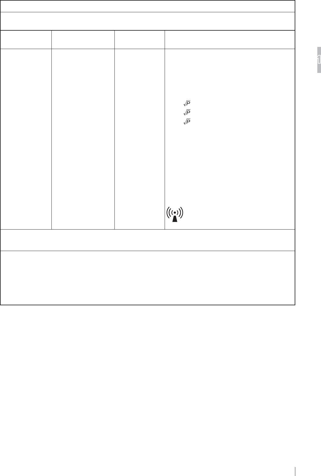
Table 3
*XLGDQFHDQGPDQXIDFWXUHU¶VGHFODUDWLRQHOHFWURPDJQHWLFLPPXQLW\
7KH'5,'LVLQWHQGHGIRUXVHLQWKHHOHFWURPDJQHWLFHQYLURQPHQWVSHFL¿HGEHORZ
The customer or the user of the DR-ID 1200 should assure that it is used in such an environment.
Immunity test IEC 60601-1-2
test level Compliance level (OHFWURPDJQHWLFHQYLURQPHQWJXLGDQFH
Conducted RF
IEC 61000-4-6
Radiated RF
IEC 61000-4-3
3 Vrms
150 kHz to 80 MHz
3 V/m
80 MHz to 2.5 GHz
3 Vrms
3 V/m
Portable and mobile RF communications equipment
should be used no closer to any part of the DR-ID
1200, including cables, than the recommended
separation distance calculated from the equation
applicable to the frequency of the transmitter.
Recommended separation distance
d = 1.2
d = 1.2 80 MHz to 800 MHz
d = 2.3 800 MHz to 2.5 GHz
where
P
is the maximum output power rating of the
transmitter in watts (W) according to the transmitter
manufacturer and
d
is the recommended separation
distance in metres (m).
)LHOGVWUHQJWKVIURP¿[HG5)WUDQVPLWWHUVDV
determined by an electromagnetic site survey,a
should be less than the compliance level in each
frequency range.b
Interference may occur in the vicinity of equipment
PDUNHGZLWKWKHIROORZLQJV\PERO
127($W0+]DQG0+]WKHKLJKHUIUHTXHQF\UDQJHDSSOLHV
127(7KHVHJXLGHOLQHVPD\QRWDSSO\LQDOOVLWXDWLRQV(OHFWURPDJQHWLFSURSDJDWLRQLVDIIHFWHGE\DEVRUSWLRQDQG
UHÀHFWLRQIURPVWUXFWXUHVREMHFWVDQGSHRSOH
D )LHOGVWUHQJWKIURP¿[HGWUDQVPLWWHUVVXFKDVEDVHVWDWLRQVIRUUDGLRFHOOXODUFRUGOHVVWHOHSKRQHVDQGODQG
mobile radios, amateur radio, AM and FM radio broadcast and TV broadcast cannot be predicted theoretically with
DFFXUDF\7RDVVHVVWKHHOHFWURPDJQHWLFHQYLURQPHQWGXHWR¿[HG5)WUDQVPLWWHUVDQHOHFWURPDJQHWLFVLWHVXUYH\
VKRXOGEHFRQVLGHUHG,IWKHPHDVXUHG¿HOGVWUHQJWKLQWKHORFDWLRQLQZKLFKWKH'5,'LVXVHGH[FHHGVWKH
applicable RF compliance, the DR-ID 1200 should be observed to verify normal operation. If abnormal performance
is observed, additional measures may be necessary, such as reorienting or relocating the DR-ID 1200.
E 2YHUWKHIUHTXHQF\UDQJHN+]WR0+]¿HOGVWUHQJWKVKRXOGEHOHVVWKDQ9P

1-16
For Safe Operation
1
FDR D-EVO
II Operation Manual 897N120339A
Table 4
Recommended separation distances between
3RUWDEOHDQGPRELOH5)FRPPXQLFDWLRQVHTXLSPHQWDQGWKH'5,'
The DR-ID 1200 is intended for use in the electromagnetic environment in which radiated RF disturbances are
controlled.
The customer or the user of the DR-ID 1200 can help prevent electromagnetic interference by maintaining a
minimum distance between portable and mobile RF communications equipment (transmitters) and the DR-ID 1200 as
recommended below, according to the maximum output power of the communications equipment.
Rated maximum output
power of transmitter
W
6HSDUDWLRQGLVWDQFHDFFRUGLQJWRIUHTXHQF\RIWUDQVPLWWHU
m
150 kHz to 80 MHz
d = 1.2
80 MHz to 800 MHz
d = 1.2
800 MHz to 2.5 GHz
d = 2.3
0.01 0.12 0.12 0.23
0.1 0.38 0.38 0.73
1 1.2 1.2 2.3
10 3.8 3.8 7.3
100 12 12 23
For transmitters rated at a maximum output power not listed above, the recommended separation distance
d
in metres
(m) can be estimated using the equation applicable to the frequency of the transmitter, where
P
is the maximum output
power rating of the transmitter in watts (W) according to the transmitter manufacturer.
127( $W0+]DQG0+]WKHVHSDUDWLRQGLVWDQFHIRUWKHKLJKHUIUHTXHQF\UDQJHDSSOLHV
127( 7KHVHJXLGHOLQHVPD\QRWDSSO\LQDOOVLWXDWLRQV
(OHFWURPDJQHWLFSURSDJDWLRQLVDIIHFWHGE\DEVRUSWLRQDQGUHÀHFWLRQIURPVWUXFWXUHVREMHFWVDQGSHRSOH
1-17
For Safe Operation
1
FDR D-EVO
II Operation Manual 897N120339A
1.5
3UHFDXWLRQVLQ8VLQJWKH)'5'(92
II
This section describes the precautions in using the FDR D-EVO II.
+DQGOLQJ
+DQGOHWKHÀDWSDQHOVHQVRUFDUHIXOO\VLQFHWKH\DUH
manufactured with precision.
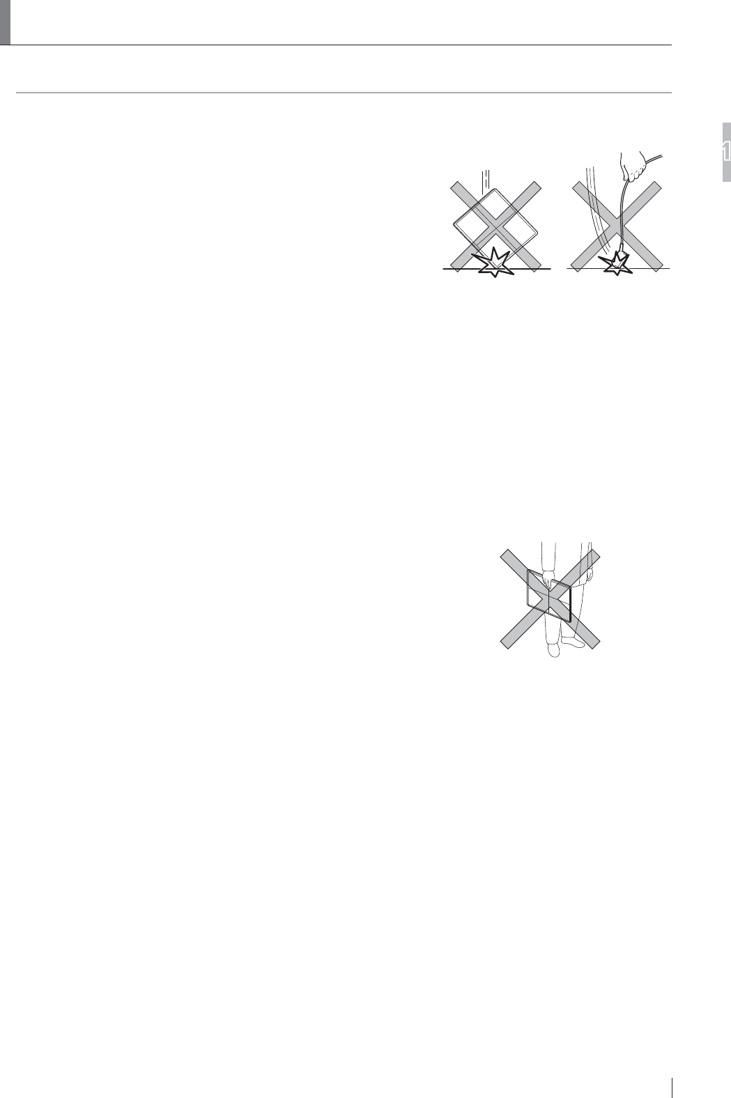
,IWKHÀDWSDQHOVHQVRURUWKH6(FRPPXQLFDWLRQFDEOHLVKLWRU
dropped or is subjected to severe shock, it may be malfunction.
Be aware of dropping the devices could result in injury or
device breakage also may cause injury.
,IWKHIURQWDQGUHDURIWKHÀDWSDQHOVHQVRUDUHVXEMHFWWR
impact by a projection, it may be damaged.
'RQRWDSSO\VWURQJSUHVVXUHRQWRWKHÀDWSDQHOVHQVRU
,IDSSOLHGWKHÀDWSDQHOVHQVRUGHIRUPVDQGWKHZDWHUSURRI
function may be compromised.
Do not pull the SE communication cable.
$OVRGRQRWSXOOWKHÀDWSDQHOVHQVRUZLWKVRPHWKLQJFDXJKWE\
the cable.
Make sure that the cable is not trapped under the wheels of a
stretcher or wheelchair.
In addition, be careful not to catch the cable when using or
storing it.
2WKHUZLVHWKHFDEOHZLOOEHGDPDJHGFDXVLQJ¿UHHOHFWULF
shock or communication failure.
'RQRWKROGWKHÀDWSDQHOVHQVRULQRQHKDQGZKHQFDUU\LQJLW
Hold it in both the hands or under the arm.
:KHQFDUU\LQJRUVWRULQJWKHÀDWSDQHOVHQVRUUHPRYHWKH
battery pack from it.
If a seal that covers a screw peels from the side surface of the
ÀDWSDQHOVHQVRUFRQWDFWD)8-,),/0GHDOHU,IWKHVHDOLVQRW
attached, artifacts caused by discharge of static electricity may
appear.
To ensure optimal image quality, it is recommended that you do
QRWXVHWKHÀDWSDQHOVHQVRUQHDUGHYLFHVPRWRUWUDQVIRUPHU
switching supply, etc.) that generate electromagnetic noise.
To ensure optimal image quality, it is recommended that you do
not place the cables (power cable, communication cable, etc.)
of the equipment near devices (motor, transformer, switching
supply, etc.) that generate electromagnetic noise and their
cables.
0DNHVXUHWKDWQROLTXLGHQWHUVWKHÀDWSDQHOVHQVRUIURP
around the battery section. In addition, when attaching the
battery pack, make sure that the waterproof packing attached
WRWKHFRQQHFWRUWHUPLQDORIWKHÀDWSDQHOVHQVRULVDOLJQHG
SURSHUO\2WKHUZLVHWKHÀDWSDQHOVHQVRUPD\EHGDPDJHG

1-18
For Safe Operation
1
FDR D-EVO
II Operation Manual 897N120339A
Do not use a multiple tap connector or extension cable for
powering the devices constituting the system.
8SWR¿YHÀDWSDQHOVHQVRUVFDQEHFRQQHFWHG,I\RXLQWHQG
WRXVHVL[RUPRUHÀDWSDQHOVHQVRUVRQO\WKH¿UVW¿YHWKDW
were connected to the image processing unit can be used.
)RUWKLVUHDVRQZKHQVL[RUPRUHÀDWSDQHOVHQVRUVDUH
registered, be careful not to use a wrong one, as you may
FRQIXVHZKLFKÀDWSDQHOVHQVRULVFRQQHFWHG
%HIRUHPDNLQJDQH[SRVXUHPDNHVXUHWKDWWKHÀDWSDQHO
VHQVRULGHQWL¿FDWLRQODPSRQWKHÀDWSDQHOVHQVRUWREH
used and the panel icon selected on the screen of the image
processing unit are the same color.
:KHQDÀDWSDQHOVHQVRULVFRPPXQLFDWLQJZLWKDSRZHU
supply unit, docking stand or access point in a room, if the
ÀDWSDQHOVHQVRULVPRYHGWRDQRWKHUURRPZKHUHWKHUHLV
another power supply unit, docking stand or access point,
FRPPXQLFDWLRQEHWZHHQWKHÀDWSDQHOVHQVRUDQGWKH
GHYLFHLQWKH¿UVWURRPPD\VWLOOEHHVWDEOLVKHG7RHVWDEOLVK
FRPPXQLFDWLRQEHWZHHQWKHÀDWSDQHOVHQVRUDQGDGHYLFH
LQWKHVHFRQGURRPFRQQHFWWKHÀDWSDQHOVHQVRUWRWKH
device with the cable or insert it into the docking stand. The
ÀDWSDQHOVHQVRULVUHFRJQL]HGDQGZLUHOHVVFRPPXQLFDWLRQ
becomes available.
'RQRWSODFHWKHFDEOHWHUPLQDORQWKHÀRRUDVGRLQJVRPD\
cause infection.
Also, clean the cable and the terminal periodically.
'RQRWLQVHUWWKHÀDWSDQHOVHQVRULQWRD&5UHDGHUXQLW
1.5.2 Before Exposure
The use of an air-conditioner may dramatically changes the temperature of the room where the
system is installed. This may cause dew condensation on the system, resulting in quality problems.
When an air-conditioner is used, change the temperature gradually to avoid temperature variation
in order not to cause dew condensation.
,IDQH[SRVXUHLVPDGHZLWKWKHIURQWDQGUHDURIWKHÀDWSDQHO
sensor facing the other way round, not only the re-exposure
is required but electric parts of inside the equipment may be
damaged.
Exposure plane of the
flat panel sensor
1-19
For Safe Operation
1
FDR D-EVO
II Operation Manual 897N120339A
'XULQJ([SRVXUH
Before making an exposure, make sure that exposure conditions most appropriate for this system
are set.
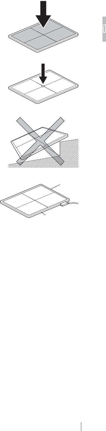
Do not apply an excessive force to the exposure plane.
7KHVHQVRULQVLGHWKHÀDWSDQHOVHQVRUPD\EHGDPDJHG
and it may not be possible to make an exposure properly.
<Load restriction>
(QWLUHVXUIDFHORDG'5,'6('5,'6('5,'6(
DQG'5,'6(
310kg (683.6 lb)
/RFDOORDG'5,'6('5,'6('5,'6(DQG
'5,'6(
160kg (352.8 lb) / ø40mm (1.6 in.)
%DVHGRQ)8-,),/0PHDVXUHPHQWVSHFL¿FDWLRQV
8VHWKHÀDWSDQHOVHQVRURQDÀDWÀRRURUSODWIRUP
When an excessive force is applied to the unit when it is tilted, the
VHQVRULQVLGHWKHÀDWSDQHOVHQVRUPD\EHGDPDJHG
Do not place a metal plate, etc., which blocks radio waves, before
WKHDQWHQQD2WKHUZLVHGDWDPD\QRWEHVHQWFRUUHFWO\IURPWKHÀDW
panel sensor.
Antenna
Antenna
1-20
For Safe Operation
1
FDR D-EVO
II Operation Manual 897N120339A
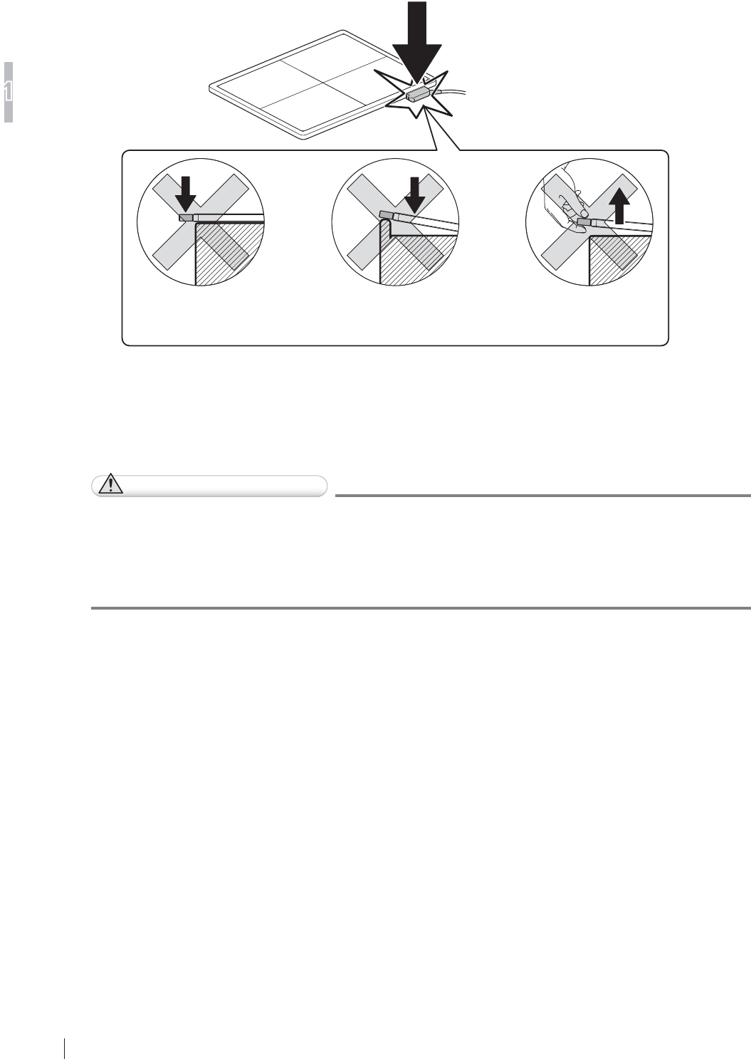
:KHQWKH6(FRPPXQLFDWLRQFDEOHLVFRQQHFWHGWRWKHÀDWSDQHOVHQVRUWRPDNHDQH[SRVXUH
on a bed, follow the precautions below. Otherwise a load may be applied locally to the SE
FRPPXQLFDWLRQFDEOHFRQQHFWRUVFDXVLQJGDPDJHWRWKHÀDWSDQHOVHQVRU
Make sure that the connector
does not protrude from the
edge of a bed
Do not place the connector
on a hard surface such as
the edge of a bed
Do not raise the flat
panel sensor by holding
only the connector
'XULQJ&OHDQLQJ
To clean the outer surfaces, use a cleaning cloth tightly wrung out of commercially available ethanol
(or diluted neutral detergent).
CAUTIONS
Ɣ %HVXUHWRWXUQRIIWKHSRZHUEHIRUHFOHDQLQJHDFKSDUWRIWKHGHYLFH
Ɣ 'RQRWXVHDQH[FHVVLYHDPRXQWRIHWKDQRORUQHXWUDOGHWHUJHQWDVGRLQJVRPD\DOORZWKH
OLTXLGWRHQWHUIURPWKHJDSRQWKHRXWHUVXUIDFHVUHVXOWLQJLQWKHGDPDJHWRWKHÀDWSDQHO
sensor, or cause the labels to come off.
Ɣ 'RQRWXVHDVROYHQWVXFKDVWKLQQHURUEHQ]LQHDVLWFRUURGHVWKHRXWHUVXUIDFHV
Ɣ )RURWKHUDYDLODEOHGLVLQIHFWDQWVFRQVXOWRXURI¿FLDOGHDOHU
6WRUDJH
:KHQWKHÀDWSDQHOVHQVRUDQGWKHLPDJHSURFHVVLQJXQLWDUHQRWLQXVHVWRUHWKHPLQDSODFH
where they do not fall or drop.
1-21
For Safe Operation
1
FDR D-EVO
II Operation Manual 897N120339A
1.5.6 Precautions Related to the Load Applied to the Flat
Panel Sensor
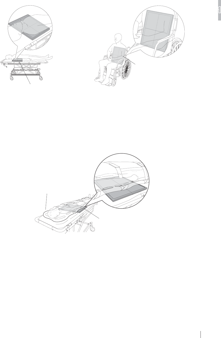
,IH[FHVVLYHORDGLVDSSOLHGWRWKHÀDWSDQHOVHQVRUXVHLWRQDÀDWÀRRURUSODWIRUP
When making an exposure for the patient in a wheelchair or adjustable bed or on a stretcher, the
ÀDWSDQHOVHQVRUPD\EHGHIRUPHGVOLJKWO\ZDUSHG
Flat panel sensor
Flat panel sensor
,QFDVHWKDWWKHÀDWSDQHOVHQVRULVGHIRUPHGPDNHVXUHWKDW;UD\LPDJHVDUHQRWDGYHUVHO\
DIIHFWHGEHIRUHFRQWLQXLQJWKHXVHRIWKHÀDWSDQHOVHQVRU
The precautions below must also be observed when making an exposure.
'RQRWKDYHWKHSDWLHQWVWDQGRQWKHÀDWSDQHOVHQVRU
'RQRWSODFHWKHKDUGGHYLFHVVXFKDVVSLQHERDUGRQWKHÀDWSDQHOVHQVRU
([FHVVLYHORDGLVDSSOLHGORFDOO\DQGWKHÀDWSDQHOVHQVRUPD\EHGDPDJHG
Flat panel sensor
Spine board
(YHQZKHQWKHÀDWSDQHOVHQVRULVXVHGRQDÀDWÀRRURUSODWIRUPLWPD\EHGDPDJHGLIWKHDSSOLHG
load exceeds the limit.

1-22
For Safe Operation
1
FDR D-EVO
II Operation Manual 897N120339A
1.5.7 Radio Waves
:LUHOHVVVSHFL¿FDWLRQVIRUWKHÀDWSDQHOVHQVRUDQGDFFHVVSRLQWDUHDVIROORZV
)ODWSDQHOVHQVRU $FFHVVSRLQWRSWLRQDO
:LUHOHVVVSHFLILFDWLRQ ,(((Q ,(((Q
7UDQVPLWIUHTXHQF\ *+] *+]
0RGXODWLRQ OFDM OFDM
)UHTXHQF\WROHUDQFH SSP SSP
'DWDWUDQVIHUUDWH 0ESV 0ESV
7UDQVIHUSRZHU G%PRUOHVV G%PRUOHVV
)RUZLUHOHVVVSHFL¿FDWLRQVRIWKHLPDJHSURFHVVLQJXQLWVHH³'5,'&/2SHUDWLRQ0DQXDO´
CAUTIONS
Ɣ Radio waves available outdoors vary, depending on the country where the system is used.
(For U.S.)
Radio waves in the 5.2GHz frequency band can be used indoors only.
When radio waves in the 5.3GHz and 5.6GHz frequency bands are selected, the DFS function
will operate.
Ɣ When the FDR D-EVO II and any other wireless equipment are operating on the same
frequency channel in a hospital, it may take time to show an image on the image processing
unit monitor.
CAUTIONS
7KHDYDLODEOHVFLHQWL¿FHYLGHQFHGRHVQRWVKRZWKDWDQ\KHDOWKSUREOHPVDUHDVVRFLDWHGZLWK
using low power wireless devices. There is no proof, however, that these low power wireless
devices are absolutely safe. Low power Wireless devices emit low levels of radio frequency
energy (RF) in the microwave range while being used. Whereas high levels of RF can produce
health effects (by heating tissue), exposure of low-level RF that does not produce heating effects
causes no known adverse health effects. Many studies of low-level RF exposures have not found
any biological effects. Some studies have suggested that some biological effects might occur,
EXWVXFK¿QGLQJVKDYHQRWEHHQFRQ¿UPHGE\DGGLWLRQDOUHVHDUFK'5,'6('5,'6(
'5,'6('5,'6(KDVEHHQWHVWHGDQGIRXQGWRFRPSO\ZLWK)&&,&UDGLDWLRQH[SRVXUH
OLPLWVVHWIRUWKIRUDQXQFRQWUROOHGHQYLURQPHQWDQGPHHWVWKH)&&UDGLRIUHTXHQF\5)([SRVXUH
*XLGHOLQHVDQG566RIWKH,&UDGLRIUHTXHQF\5)([SRVXUHUXOHV
/HVFRQQDLVVDQFHVVFLHQWL¿TXHVGRQWQRXVGLVSRVRQVQ¶RQWPLVHQpYLGHQFHDXFXQSUREOqPHGH
VDQWpDVVRFLpjO¶XVDJHGHVDSSDUHLOVVDQV¿OjIDLEOHSXLVVDQFH1RXVQHVRPPHVFHSHQGDQWSDV
HQPHVXUHGHSURXYHUTXHFHVDSSDUHLOVVDQV¿OjIDLEOHSXLVVDQFHVRQWHQWLqUHPHQWVDQVGDQJHU
/HVDSSDUHLOVVDQV¿OjIDLEOHSXLVVDQFHpPHWWHQWXQHpQHUJLHUDGLRpOHFWULTXH5)WUqVIDLEOHGDQV
OHVSHFWUHGHVPLFURRQGHVORUVTX¶LOVVRQWXWLOLVpV$ORUVTX¶XQHGRVHpOHYpHGH5)SHXWDYRLUGHV
HIIHWVVXUODVDQWpHQFKDXIIDQWOHVWLVVXVO¶H[SRVLWLRQjGHIDLEOHV5)TXLQHSURGXLVHQWSDVGH
FKDOHXUQ¶DSDVGHPDXYDLVHIIHWVFRQQXVVXUODVDQWp'HQRPEUHXVHVpWXGHVRQWpWpPHQpHV
VXUOHVH[SRVLWLRQVDX[5)IDLEOHVHWQ¶RQWGpFRXYHUWDXFXQHIIHWELRORJLTXH&HUWDLQHVpWXGHV
RQWVXJJpUpTX¶LOSRXYDLW\DYRLUFHUWDLQVHIIHWVELRORJLTXHVPDLVFHVUpVXOWDWVQ¶RQWSDVpWp
FRQ¿UPpVSDUGHVUHFKHUFKHVVXSSOpPHQWDLUHV'5,'6('5,'6('5,'6('5,'
6(DpWpWHVWpHWMXJpFRQIRUPHDX[OLPLWHVG¶H[SRVLWLRQDX[UD\RQQHPHQWVpQRQFpHVSRXU
XQHQYLURQQHPHQWQRQFRQWU{OpHWUHVSHFWHOHVUqJOHVOHVUDGLRpOHFWULTXHV5)GHOD)&&OLJQHV
GLUHFWULFHVG¶H[SRVLWLRQHWG¶H[SRVLWLRQDX[IUpTXHQFHVUDGLRpOHFWULTXHV5)&15GHO¶,&
1-23
For Safe Operation
1
FDR D-EVO
II Operation Manual 897N120339A
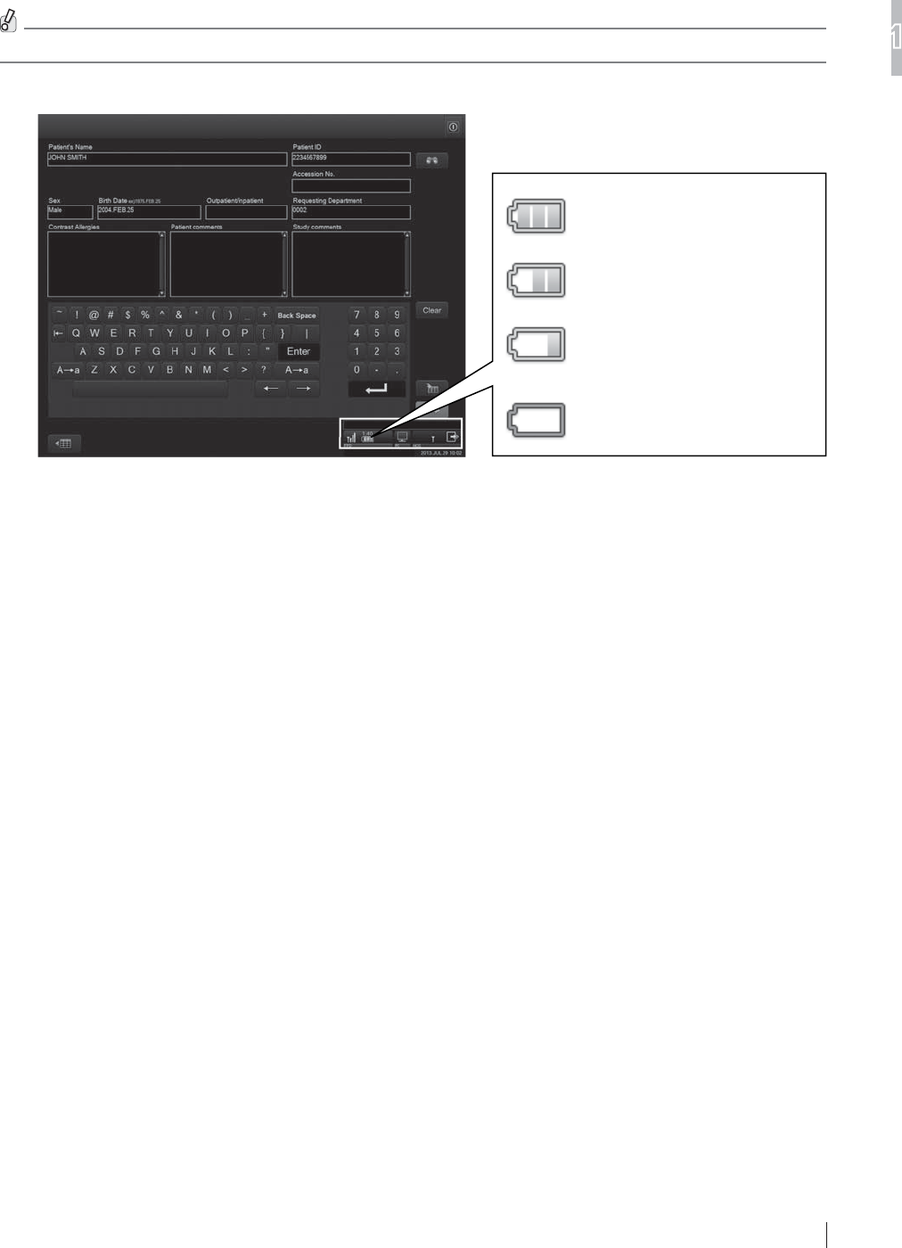
%DWWHU\3DFN6WDWXV,QGLFDWRU
7KHVWDWXVDQGRSHUDEOHWLPHRIWKHEDWWHU\SDFNXVHGIRUWKHÀDWSDQHOVHQVRUDUHVKRZQE\WKH
exposure unit battery indicator in the connected devices status at the lower right of the image
processing unit’s display.
The battery pack status indicator shows the remaining capacity of the battery pack. Each icon is
described below.
For details of the connected devices status, see the “Console Advance (DR-ID 300CL) Reference Guide”.
5HDG\IRUH[SRVXUH
5HDG\IRUH[SRVXUH
5HDG\IRUH[SRVXUH
(The remaining battery capacity is
low. Charge the battery pack.)
1RWUHDG\IRUH[SRVXUH
&KHFNWKHRSHUDEOHWLPHRQWKHLPDJHSURFHVVLQJXQLW¶VGLVSOD\ZKHQWKHÀDWSDQHOVHQVRULVLQXVH
Note that the displayed time differs, depending on the mode being used.
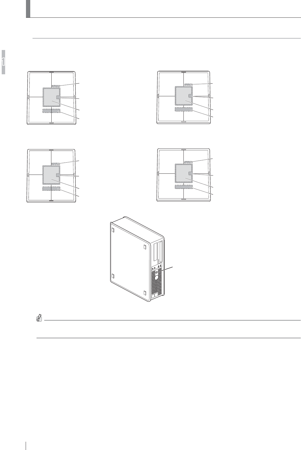
1-24
For Safe Operation
1
FDR D-EVO
II Operation Manual 897N120339A
1.6 Locations of Labels and Signs
/RFDWLRQVRIODEHOVDQGVLJQVDI¿[HGWRWKH)'5'(92IIDQGWKHUHOHYDQWVDIHW\VLJQVDUHVKRZQ
EHORZ
1.6.1 Locations of Labels
Serial Number Label
DR-ID 1202SE
Radio Law Certification Label
Battery Cover Label
DR-ID 1202SE Identification Label
([SRVXUHSODQH!
)ODWSDQHOVHQVRU'5,'6(
Serial Number Label
DR-ID 1212SE
Radio Law Certification Label
Battery Cover Label
DR-ID 1212SE Identification Label
([SRVXUHSODQH!
)ODWSDQHOVHQVRU'5,'6(
Serial Number Label
DR-ID 1201SE
Radio Law Certification Label
Battery Cover Label
DR-ID 1201SE Identification Label
([SRVXUHSODQH!
)ODWSDQHOVHQVRU'5,'6(
Serial Number Label
DR-ID 1211SE
Radio Law Certification Label
Battery Cover Label
DR-ID 1211SE Identification Label
([SRVXUHSODQH!
)ODWSDQHOVHQVRU'5,'6(
Main switch/
power status LED
&RQWUROFDELQHW'5,'0&
,IWKHFRQWUROFDELQHWLVQRWLQFOXGHGLQWKHV\VWHPWKH'5,'0&LGHQWL¿FDWLRQODEHOLVSODFHGRQWKH&'
FDVHRIWKHVRIWZDUHIRUWKHFRQWUROFDELQHW
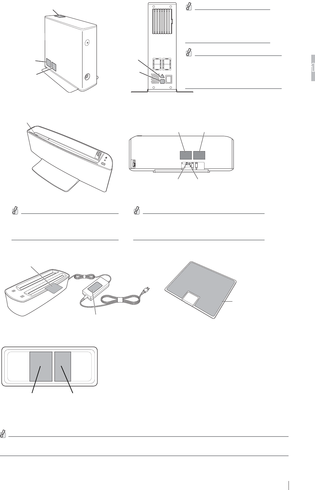
1-25
For Safe Operation
1
FDR D-EVO
II Operation Manual 897N120339A
Power supply unit (DR-ID 1200MP)
DR-ID 1200PU
System Label
Do Not Step On
This Surface label
DR-ID 1200PU
Rating Label
DR-ID 1200MP
Caution Label 1
DR-ID 1200MP
Caution Label 2
For the types of connectable
FDEOHVFRQVXOWRXURI¿FLDO
dealer or FUJIFILM
Representative
Pour en savoir plus sur les
types de câbles connectables,
contactez notre revendeur agréé
ou notre représentant FUJIFILM.
Docking stand (DR-ID 1200DS)
Do Not Step On This Surface label DR-ID 1200DU
System Label
DR-ID 1200DS
Caution Label 1
DR-ID 1200DU
Rating Label
DR-ID 1200DS
Caution Label 2
Pour en savoir plus sur les types de câbles
connectables, contactez notre revendeur
agréé ou notre représentant FUJIFILM.
For the types of connectable cables,
FRQVXOWRXURI¿FLDOGHDOHU
or FUJIFILM Representative
Battery pack (optional)
Battery pack
Rating Label
AC Adapter Rating Label
Battery Charger Rating Label
Battery Charger (optional)
Access Point
Product Label
Access Point
Radio Law Certification Label
Access point (optional)
For details on the locations of labels for the image processing unit, see the “Console Advance (DR-ID 300CL)
Operation Manual”.
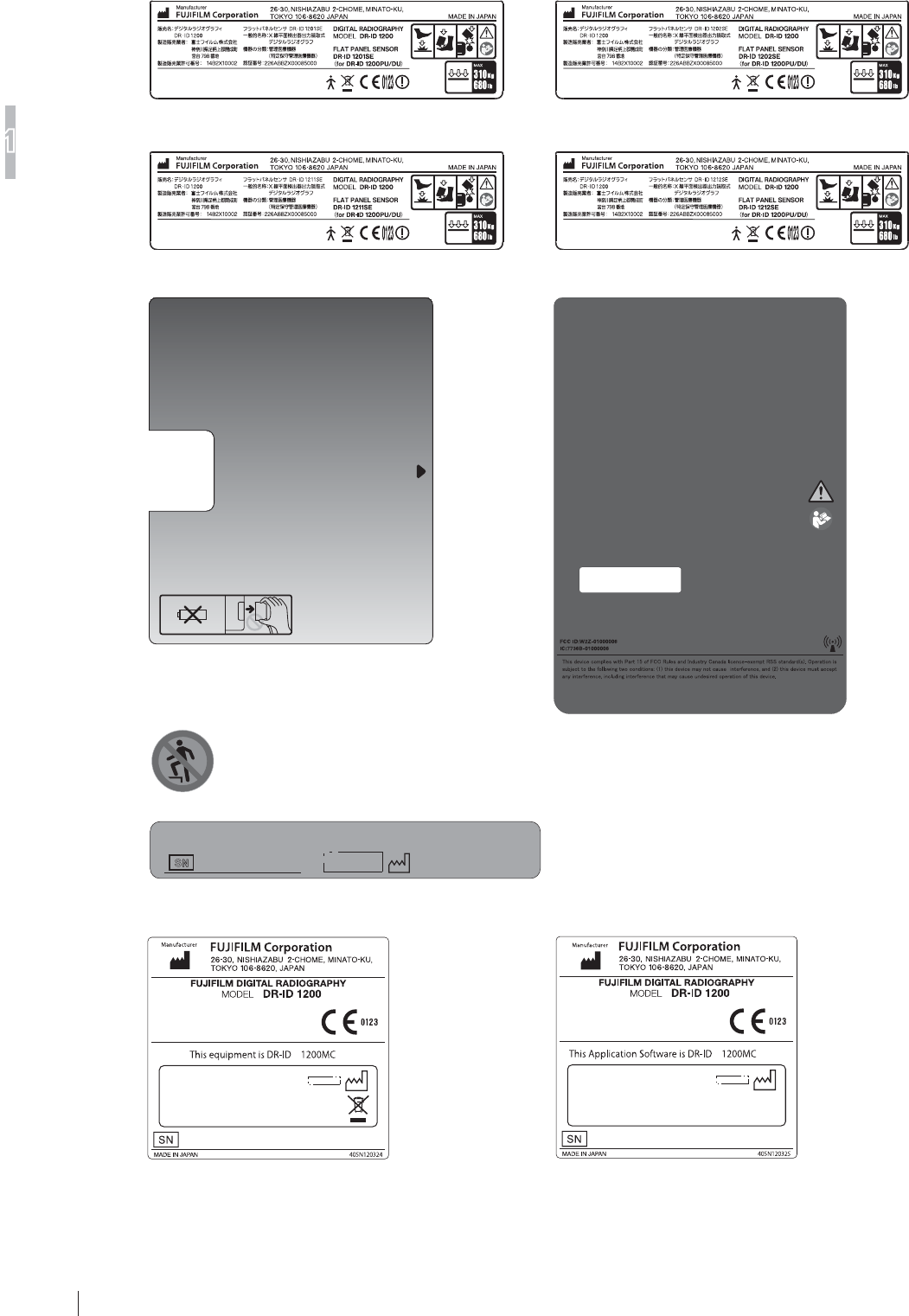
1-26
For Safe Operation
1
FDR D-EVO
II Operation Manual 897N120339A
1.6.2 DR-ID 1200
DR-ID 1201SE Identification Label DR-ID 1202SE Identification Label
DR-ID 1211SE Identification Label DR-ID 1212SE Identification Label
Do Not Step On This Surface label
Battery Cover Label
S
N
Serial Number Label
DR-ID 1201SE/DR-ID 1202SE/
DR-ID 1211SE/DR-ID 1212SE
Radio Law Certification Label
DR-ID 1200MC Identification Label DR-ID 1200MC Identification Label
(for the system without the DR-ID 1200MC)
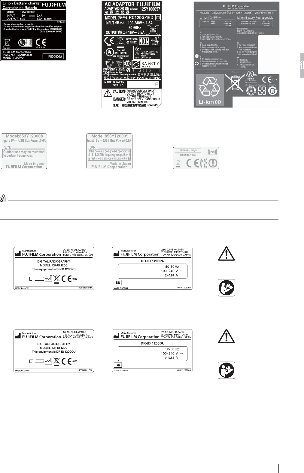
1-27
For Safe Operation
1
FDR D-EVO
II Operation Manual 897N120339A
AC Adapter (Battery Charger)
Rating Label
Battery Pack Rating Label
Battery Charger Rating Label
Access Point Product Label
(for Europe)
Access Point Product Label
(for North America)
Access Point
Radio Law Certification Label
For details on the labels of the image processing unit, see the “Console Advance (DR-ID 300CL) Operation
Manual”.
1.6.3 DR-ID 1200PU
DR-ID 1200PU System Label DR-ID 1200MP
Caution Label 2
DR-ID 1200MP
Caution Label 1
DR-ID 1200PU Rating Label
1.6.4 DR-ID 1200DU
DR-ID 1200DU System Label DR-ID 1200DS
Caution Label 2
DR-ID 1200DS
Caution Label 1
DR-ID 1200DU Rating Label
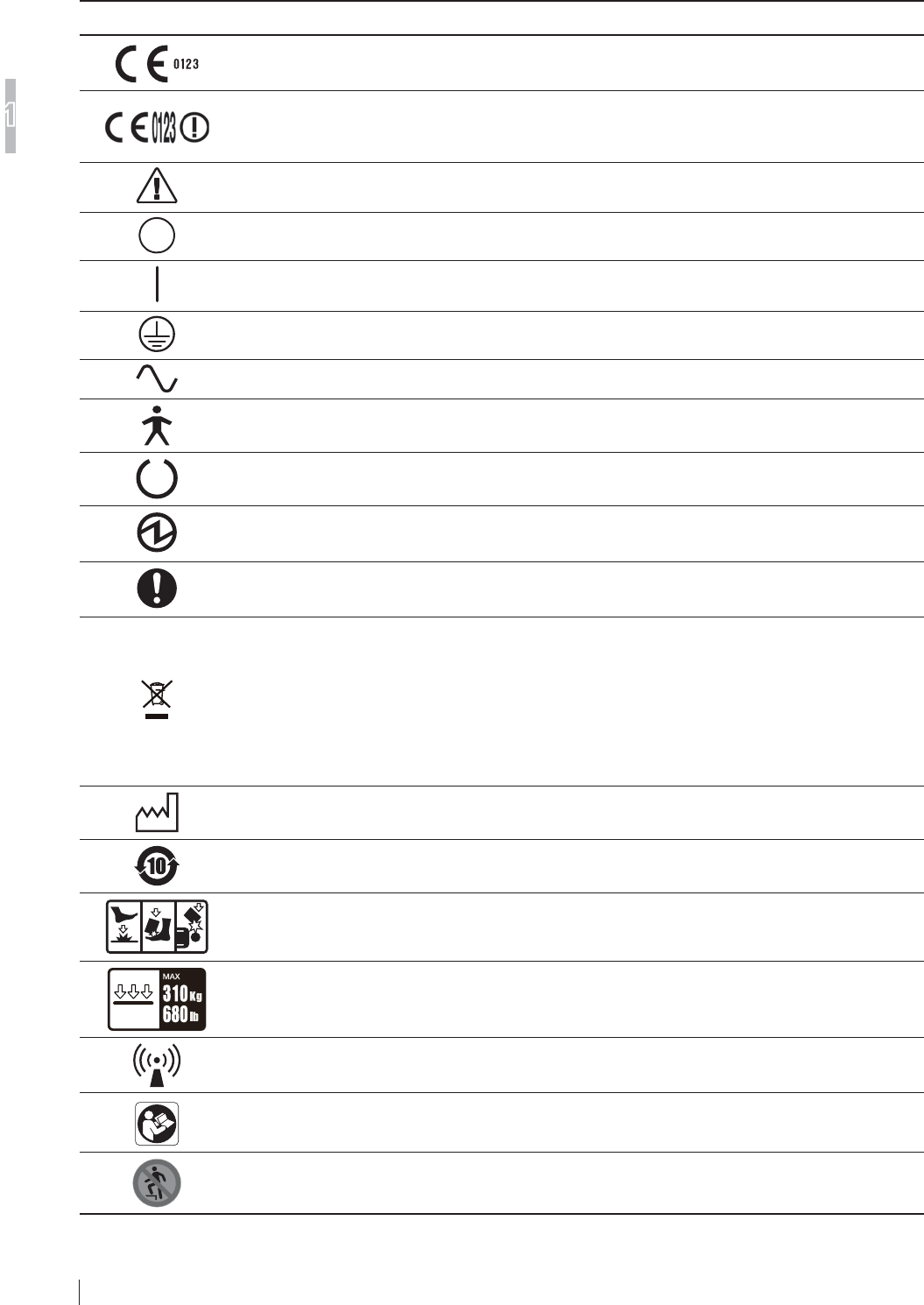
1-28
For Safe Operation
1
FDR D-EVO
II Operation Manual 897N120339A
1.6.4 Safety and Other Symbols
The following safety symbols are used in the labels or on its body.
Symbol Description
This symbol indicates compliance of the equipment with Directive 93/42/EEC.
This symbol indicates compliance of the equipment with Directive 93/42/EEC.
7KLVV\PEROLQGLFDWHVWKDWWKHHTXLSPHQWLVFODVVL¿HGDV&ODVVHTXLSPHQWLQWKH577(
Directive.
Caution (See “1.6.1 Locations of Labels” (page 1-24).)
OFF (To indicate disconnection from the mains, at least for mains switches or their positions,
and all those cases where safety is involved.)
ON (To indicate connection to the mains, at least for mains switches or their positions, and all
those cases where safety is involved.)
Protective earth (ground)
Alternating current
This symbol indicates that the equipment is a Type B Applied Part.
Ready (To indicate the machine is ready for operation.)
Electric energy
General mandatory action sign
This symbol indicates that this product is not to be disposed of with your household waste,
according to the WEEE Directive (2002/96/EC) and your national law. This product should be
handed over to a designated collection point.
Improper handling of this type of waste could have a possible negative impact on the environment
and human health due to potentially hazardous substances that are generally associated with EEE.
At the same time, your cooperation in the correct disposal of this product will contribute to the
effective usage of natural resources.
)RUPRUHLQIRUPDWLRQDERXWZDVWHSOHDVHFRQWDFWRXURI¿FLDOGHDOHURU)8-,),/05HSUHVHQWDWLYH
Year of manufacture
Environmentally Friendly Use Period (EFUP)
Caution for local load (See “1.5.3 During Exposure” (page 1-19).) /
'RQRWGURSWKHÀDWSDQHOVHQVRUWRWKHXVHUSDWLHQW
Entire surface load
This symbol includes RF transmitters or indicates equipment that intentionally applies RF
electromagnetic energy for diagnosis or treatment.
Refer to Instruction Manual/Booklet
No stepping on surface
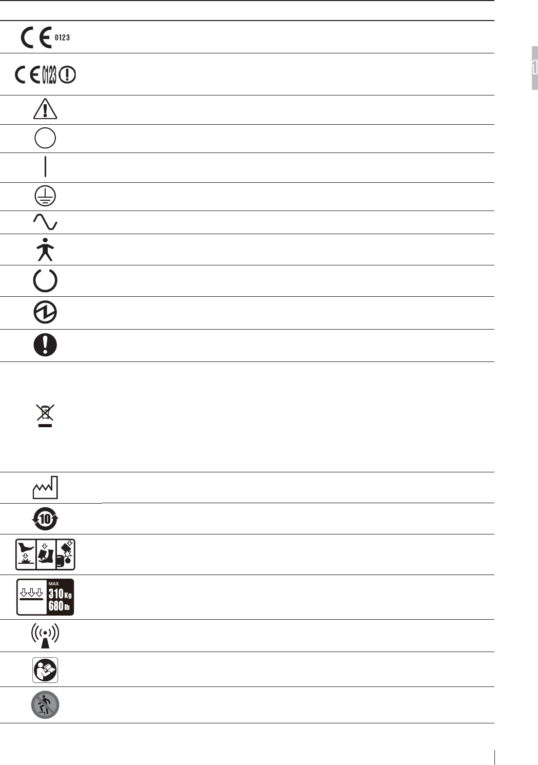
1-29
For Safe Operation
1
FDR D-EVO
II Operation Manual 897N120339A
1.6.5 Symboles de sécurité et autres
Les symboles de sécurité suivants sont utilisés sur les étiquettes ou sur le corps de l’équipement.
Symbole Description
Ce symbole indique la conformité de l’équipement à la directive 93/42/CEE.
Ce symbole indique la conformité de l’équipement à la directive 93/42/CEE.
&HV\PEROHLQGLTXHTXHO¶pTXLSHPHQWDSSDUWLHQWjODFDWpJRULHGHODFODVVL¿FDWLRQGHOD
GLUHFWLYH577(
Attention (Voir « 1.6.1 Emplacement des étiquettes » (page 1-24).)
HORS TENSION (Pour indiquer une déconnexion de l’alimentation secteur, au moins au niveau des
interrupteurs secteurs ou leur position, et tous les cas dans lesquels la sécurité est en jeu.)
SOUS TENSION (Pour indiquer une connexion à l’alimentation secteur, au moins au niveau des
interrupteurs secteurs ou leur position, et tous les cas dans lesquels la sécurité est en jeu.)
Protection via mise à la terre (masse)
Courant alternatif
Ce symbole indique que l’équipement est une pièce appliquée de type B.
Prêt (Pour indiquer que la machine est prête à être utilisée.)
Énergie électrique
Symbole général d’action obligatoire
Ce symbole indique que ce produit ne doit pas être mis au rebut avec les déchets ménagers,
conformément à la directive DEEE (2002/96/CE) et à la législation nationale en vigueur. Ce produit
doit être remis à un centre de collecte approprié.
Une manipulation incorrecte de ce type de déchet peut avoir un impact négatif sur l’environnement
et sur la santé humaine, en raison des substances potentiellement dangereuses généralement
associées aux EEE.
Votre coopération pour la mise au rebut correcte de ce produit contribuera en outre à une utilisation
HI¿FDFHGHVUHVVRXUFHVQDWXUHOOHV
Pour en savoir plus sur les déchets, contactez notre revendeur agréé ou notre représentant FUJIFILM.
Année de fabrication
Attention relative à une charge placée de façon localisée /
Ne faites pas tomber le détecteur à panneau plat sur l’utilisateur/le patient
Charge sur l’intégralité de la surface
Ce symbole inclut les émetteurs RF ou indique un équipement émettant intentionnellement de
O¶pQHUJLHpOHFWURPDJQpWLTXH5)jGHV¿QVGHGLDJQRVWLFRXGHWUDLWHPHQW
Consultez le mode d’emploi
Ne montez pas sur la surface
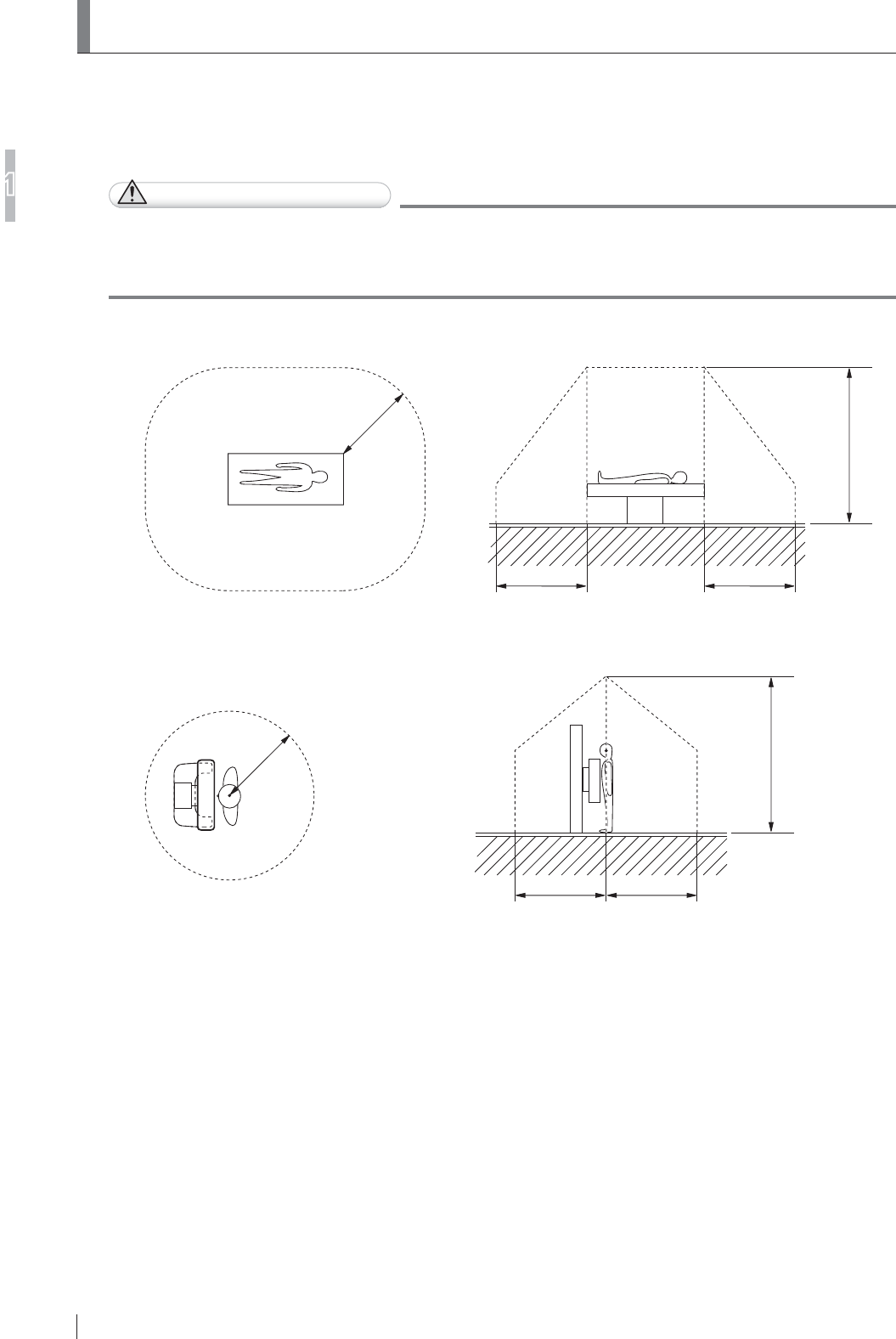
1-30
For Safe Operation
1
FDR D-EVO
II Operation Manual 897N120339A
1.7 Installation Conditions
'H¿QLWLRQRI3DWLHQW(QYLURQPHQW
)RUWKHSURGXFWVWKDWFDQEHLQVWDOOHGLQSDWLHQWHQYLURQPHQWVHH³6\VWHP&RQ¿JXUDWLRQ´
(page 2-1).
CAUTIONS
,QWKH;UD\URRPGRQRWLQVWDOOWKHSRZHUVXSSO\XQLWFRQWUROFDELQHWGRFNLQJVWDQGDFFHVV
SRLQWLPDJHSURFHVVLQJXQLWDQGEDWWHU\FKDUJHURSWLRQDOLQDUHDVZKHUHWKHXVHUFRXOG
easily trip over them. Falls could result in injury.
Ŷ %HGLQDSDWLHQWURRPRUEHGW\SHUDGLRJUDSKLFH[DPLQDWLRQVWDQG
2.5m
(8.2 ft) 2.5m
(8.2 ft)
2.5m
(8.2 ft)
2.5m
(8.2 ft)
Ŷ 8SULJKWW\SHUDGLRJUDSKLFH[DPLQDWLRQVWDQG
2.5m
(8.2 ft) 2.5m
(8.2 ft)
2.5m
(8.2 ft)
2.5m
(8.2 ft)
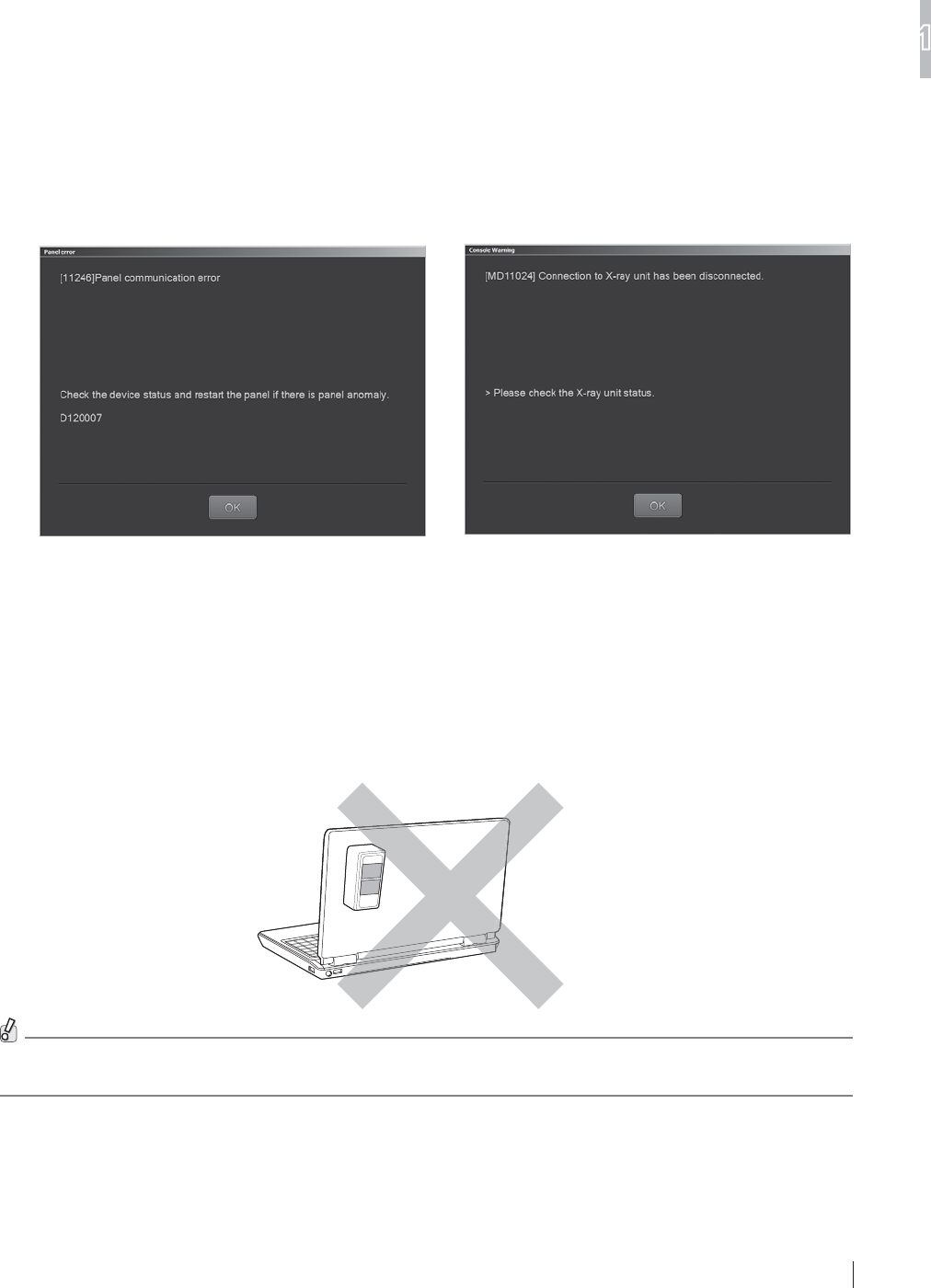
1-31
For Safe Operation
1
FDR D-EVO
II Operation Manual 897N120339A
1.7.2 Installation Precautions
Ŷ 8VLQJLQDQRSHQVSDFH
,QVWDOOWKHÀDWSDQHOVHQVRUWKHDFFHVVSRLQWDQGWKHLPDJHSURFHVVLQJXQLWDWDGLVWDQFHRIOHVV
than 10m (32.8 ft) from each other. If any distance is over 10m (32.8 ft), a wireless communication
error may occur.
Ŷ 8VLQJLQDQ;UD\URRP
The access point should be installed in the X-ray room.
If the access point is not installed properly, wireless communication may become unstable.
If this happens, the messages below may appear.
These messages are only examples.
Example 1
Panel communication error
Example 2
Connection to X-ray unit has been disconnected.
3UHFDXWLRQVIRU,QVWDOOLQJWKH$FFHVV3RLQW2SWLRQDO
Install the optional access point in a place where the operation is not hindered.
When the access point is installed onto a personal computer, be sure that the label attached on the
access point does not face the front side.
In addition, install the access point in an appropriate place to prevent it from colliding with a moving mobile X-ray
unit. If any impact is applied to the optional access point, it may be damaged.

1-32
For Safe Operation
1
FDR D-EVO
II Operation Manual 897N120339A
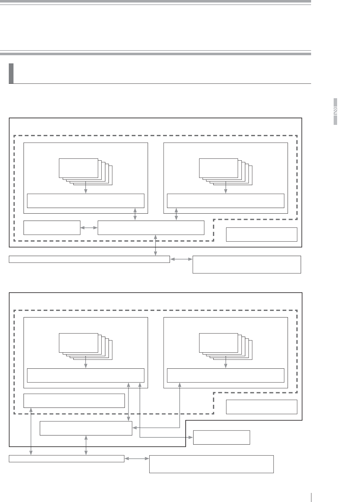
2-1
6\VWHP&RQILJXUDWLRQ3URGXFW2YHUYLHZ
2
FDR D-EVO
II Operation Manual 897N120339A
Chapter 26\VWHP&RQILJXUDWLRQ
(Product Overview)
2.1 FDR D-EVO
II
6\VWHP&RQ¿JXUDWLRQ
(When the optional access point is used)
DIGITAL RADIOGRAPHY DR-ID 1200
PANEL UNIT DR-ID 1200PU
Image processing unit of other
digital radiography system DR-ID 300CL
Hub
Battery charger
Power supply unit DR-ID 1200MP
Flat panel
sensor
Image processing unit DR-ID 300CL*1, *3
DOCKING UNIT DR-ID 1200DU
Docking stand DR-ID 1200DS
Flat panel
sensor
Access point
(When an access point installed in the hospital is used)
DIGITAL RADIOGRAPHY DR-ID 1200
PANEL UNIT DR-ID 1200PU
Hub
Battery charger
Power supply unit DR-ID 1200MP
Flat panel
sensor
Image processing unit DR-ID 300CL*3
DOCKING UNIT DR-ID 1200DU
Docking stand DR-ID 1200DS
Flat panel
sensor
Access point
Control cabinet DR-ID 1200MC*2
Image processing unit of other
digital radiography system DR-ID 300CL

2-2
System Configuration (Product Overview)
2
FDR D-EVO
II Operation Manual 897N120339A
• The products in can be installed in patient environment.
However, the image processing unit cannot be installed while it is being charged.
• The FDR D-EVO II consists of the panel unit DR-ID 1200PU or docking unit DR-ID 1200DU, the
control cabinet DR-ID 1200MC and the image processing unit.
7KHSDQHOXQLW'5,'38FRQVLVWVRIWKHÀDWSDQHOVHQVRU'5,'6('5,'6(
DR-ID 1211SE and DR-ID 1212SE, and the power supply unit DR-ID 1200MP.
• The panel unit DR-ID 1200PU can be operated in conjunction with the X-ray equipment, and it can
be used for exposures in wired mode.
7KHGRFNLQJXQLW'5,''8FRQVLVWVRIWKHÀDWSDQHOVHQVRU'5,'6('5,'6(
DR-ID 1211SE and DR-ID 1212SE, and the docking stand DR-ID 1200DS.
• With the docking unit DR-ID 1200DU, the exposure ready status can be displayed with the lamp
RQWKHGRFNLQJVWDQG,QDGGLWLRQWKHÀDWSDQHOVHQVRUWREHXVHGIRUH[SRVXUHFDQEHLGHQWL¿HG
with the lamp indication on the docking stand.
7KHLPDJHSURFHVVLQJXQLW'5,'&/LVFRQ¿JXUHGE\LQVWDOOLQJLPDJHSURFHVVLQJVRIWZDUHRQ
a commercially available personal computer conforming to IEC 60950-1 or equivalent.
8SWR¿YHÀDWSDQHOVHQVRUVFDQEHFRQQHFWHG
:KHQWKH'5,'38LVXVHGXSWRWZRÀDWSDQHOVHQVRUVFDQEHFRQQHFWHGWRRQHSRZHU
VXSSO\XQLWLQZLUHGFRPPXQLFDWLRQPRGH8SWRWZRSRZHUVXSSO\XQLWFDQEHXVHG:KHQWKHÀDW
panel sensors are used with three to four different techniques, two power supply units are required.
:KHQWKH'5,''8LVXVHGRQO\RQHÀDWSDQHOVHQVRUVFDQEHFRQQHFWHGWRRQHGRFNLQJ
stand in wired communication mode. Up to three docking stand can be used.
• When the DR-ID 1200DU and a mobile X-ray unit are used, power to the access point is supplied by
connecting it to the image processing unit DR-ID 300CL.
*1 The software for the control cabinet is installed on the image processing unit (DR-ID 300CL).
'HSHQGLQJRQWKHFRQ¿JXUDWLRQWKHFRQWUROFDELQHW'5,'0&PD\QRWEHLQFOXGHGLQ
the system. If not included, the software for the control cabinet can be installed on the image
processing unit (DR-ID 300CL).
)RUGHWDLOVSHFL¿FDWLRQRILPDJHSURFHVVLQJXQLWSOHDVHUHIHUWR³'5,'&/2SHUDWLRQ
Manual”.
*3 When the image processing unit (DR-ID 300CL) is used in patient environment, run the notebook
computer on battery power.

2-3
System Configuration (Product Overview)
2
FDR D-EVO
II Operation Manual 897N120339A
2.1.2 Features of the FDR D-EVO II
This section describes the main features of the FDR D-EVO II.
/LJKWZHLJKWWKLQDQGURXQGLVKGHVLJQRIWKHÀDWSDQHOVHQVRUIDFLOLWDWHVOLIWLQJDQG
enhances operability, for example, when it is set under a patient lying on a bed.
2 By utilizing FUJIFILM’s proprietary ISS (Irradiation Side Sampling) method, vapor
deposition technique of CsI scintillator, particle blend technique of GOS scintillator, and also
noise reduction IC, images with high sensitivity and high sharpness are obtained even in
low-density areas.
3 After an X-ray irradiation process is completed, the exposed image appears on the monitor
of the image processing unit in about one second at the shortest. In addition, since images
are compressed with our unique compression technology (CIP) during communication,
H[SRVXUHVFDQEHPDGHHI¿FLHQWO\DWVKRUWLQWHUYDOV
7KHÀDWSDQHOVHQVRUKDVVOHHSPRGHDQGH[WUDVOHHSPRGH7KLVSRZHUVDYLQJGHVLJQ
almost eliminates the need of replacing the battery pack. In addition, since a removable
battery pack is adopted, it can be replaced even if the battery runs down.
5 The docking stand and the optional battery charger assist smooth exposure operations.
The system can be used even in an emergency since only 3 minutes of charge time are
required to make about 30 exposures.
8SWRLPDJHVFDQEHVWRUHGWHPSRUDULO\LQWKHPHPRU\RIWKHÀDWSDQHOVHQVRU
The memory exposure mode can be activated easily by operating the button on the back of
WKHÀDWSDQHOVHQVRU(YHQLIWKHLPDJHSURFHVVLQJXQLWLVQRWDYDLODEOHH[SRVXUHVFDQEH
PDGHRQO\E\XVLQJWKHÀDWSDQHOVHQVRU
7 Extended Image Readout enables a long exposure for up to ten seconds.
7KHÀDWSDQHOVHQVRUFDQEHXVHGFOHDQO\VLQFHDOOVXUIDFHVKDYHEHHQFRDWHGZLWKDQ
antibacterial agent.
6LQFHWKHH[WHUQDOGLPHQVLRQVDQGWKLFNQHVVRIWKHÀDWSDQHOVHQVRUDUHWKHVDPHDVWKRVH
RIH[LVWLQJFDVVHWWHIRUJHQHUDOH[SRVXUHFRPSOLDQWZLWK,62WKHÀDWSDQHOVHQVRU
can be loaded onto the exposure stand that has been used. In addition, since operation on
EDWWHU\SRZHUDQGZLUHOHVVFRPPXQLFDWLRQDUHDYDLODEOHRQHÀDWSDQHOVHQVRUFDQEHXVHG
for multiple devices such as upright type and supine-position type radiography devices.
7KHÀDWSDQHOVHQVRUKDVWKH;UD\DXWRPDWLFGHWHFWLRQIXQFWLRQ6PDUW6ZLWFK
:LWKWKLVIXQFWLRQWKHÀDWSDQHOVHQVRUGHWHFWVHYHQDVPDOODPRXQWRI;UD\SUHFLVHO\WR
start an exposure without connecting it to the X-ray device.
11 By using a notebook computer as the image processing unit, and also by using the optional
access point, the need of carrying cables is eliminated and the system can be used for
rounds.
In addition, exposures can also be made outdoors depending on the frequency band of
radio wave.
8SWRÀDWSDQHOVHQVRUVFDQEHUHJLVWHUHG$PRQJWKHUHJLVWHUHGÀDWSDQHOVHQVRUVXS
WR¿YHÀDWSDQHOVHQVRUVFDQEHXVHG
2QHDFKVLGHRIWKHÀDWSDQHOVHQVRUWKHUHLVDQ/('VKRZLQJWKHFHQWHUSRVLWLRQ7KH
FRORURIWKLV/('FDQEHVHOHFWHGIURPDPRQJ¿YHFRORUVRUDQJHSXUSOHOLPH\HOORZEOXH
DQGSLQN:KHQPXOWLSOHÀDWSDQHOVHQVRUVDUHXVHGWKH\FDQEHLGHQWL¿HGZLWKWKHFRORU
of the LED.
In addition, the battery pack level can always be checked with the indicator LED on the
EDFNRIWKHÀDWSDQHOVHQVRU
6LQFHWKHÀDWSDQHOVHQVRUFDQEHVKDUHGZLWKPXOWLSOHV\VWHPVWKHQXPEHURIÀDWSDQHO
sensors can be optimized.

2-4
System Configuration (Product Overview)
2
FDR D-EVO
II Operation Manual 897N120339A
2.2 Unit Names and the Functions
Unit names and the functions of the FDR D-EVO II are described below.
2.2.1 DR-ID 1200
Ŷ DR-ID 1200PU
Applied part
Flat panel sensor (DR-ID 1201SE, DR-ID 1202SE, DR-ID 1211SE and DR-ID 1212SE)
* Exposure plane is shown in this figure.
Flat panel sensor identification lamp
Memory exposure mode start button
Sleep release/
memory exposure
mode start button
Sleep lamp
Status lamp
Battery pack
level indicator
Memory exposure
mode status
<Front> <Back>
Power supply unit (DR-ID 1200MP)
Power status LED
Main switch
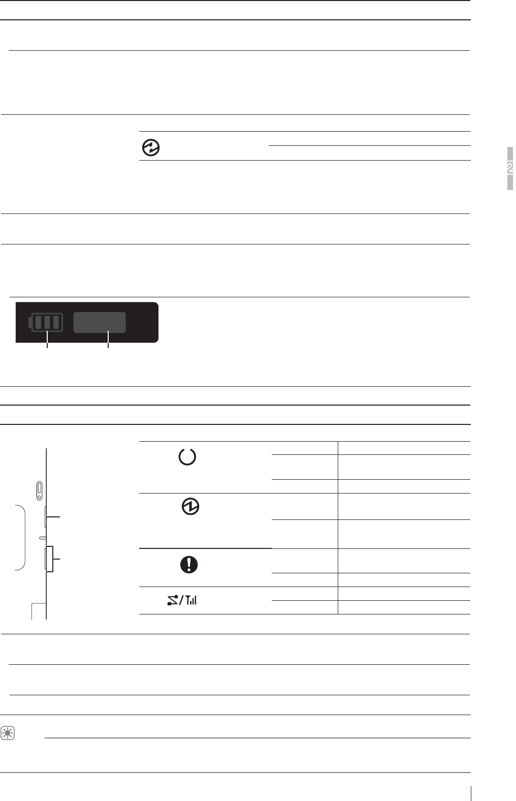
2-5
System Configuration (Product Overview)
2
FDR D-EVO
II Operation Manual 897N120339A
Name Description
Flat panel sensor The DR-ID 1201SE and DR-ID 1202SE incorporate a GOS indirect panel.
The DR-ID 1211SE and DR-ID 1212SE incorporate a CsI indirect panel.
Flat panel sensor
LGHQWL¿FDWLRQODPS
7KHÀDWSDQHOVHQVRUFXUUHQWO\LQXVHLVLGHQWL¿HGE\WKHFRORURIWKLVODPS
The color of this lamp is selected from among lime yellow, blue, purple, orange and
SLQNDWWKHWLPHRILQVWDOODWLRQ,IWKHFRORULVQRWVSHFL¿HGWKLVODPSLVOLWLQZKLWH
7KLVODPSRQWKHÀDWSDQHOVHQVRUFXUUHQWO\LQXVHLVOLWLQWKHVDPHFRORUDVWKH
panel icon selected on the display of the image processing unit.
Sleep lamp This LED shows the sleep status.
(Blue)
Off Sleep off or Sleep state
On Extra sleep state
:KHQWKHÀDWSDQHOVHQVRULVQRWRSHUDWHGIRUPLQXWHVLWLVSODFHGLQWKHVOHHS
mode.
Extra sleep mode, which can further save power, can also be set. To specify or
change the setting of sleep mode or extra sleep mode, contact a FUJIFILM dealer.
Sleep release/memory
exposure mode start button
Releases the extra sleep mode.
Memory exposure mode
start button
When this button is held pressed for 2 seconds while pressing the sleep release/
memory exposure mode start button, the memory exposure mode starts up.
The memory exposure mode can be started up when no exposure menu is
registered and calibration is not being performed.
Battery pack
level indicator
Memory exposure mode status
In the memory exposure mode, the number of exposed images or an error during the start-up
of memory exposure mode is displayed.
Name Description
Status lamp
ERROR
POWER
READY
LINK
Indicates the equipment status by LEDs.
READY (Green)
On Exposure possible
Blinks for 1.0
second During exposure sequence
Off Not ready
POWER (Blue)
(The power on/off state of the
ÀDWSDQHOVHQVRULVGLVSOD\HG
On Power ON
Off Power OFF
ERROR (Orange)
Blinks for 1.0
second Error occurred
Off Normal
LINK (White) On Connected
Off Communication not possible.
* When the battery pack is not attached, all LEDs are off.
Power supply unit
(DR-ID 1200MP)
$GHYLFHVXSSO\LQJSRZHUWRWKHÀDWSDQHOVHQVRUDQGFRQQHFWLQJEHWZHHQWKH
ÀDWSDQHOVHQVRULPDJHSURFHVVLQJXQLWDQGFRQWUROFDELQHW
Main switch 6XSSOLHVWKHSRZHUWRWKHÀDWSDQHOVHQVRUDQGWKHLQVLGHRIWKHSRZHUVXSSO\
unit.
Power status LED Displays ON/OFF of the power supply unit.
HINT
)RUGHWDLOVRQWKHÀDWSDQHOVHQVRULGHQWL¿FDWLRQODPSDQGEDWWHU\SDFNOHYHOLQGLFDWRUVHH³/DPS,QGLFDWLRQVRQ
the Flat Panel Sensor”.
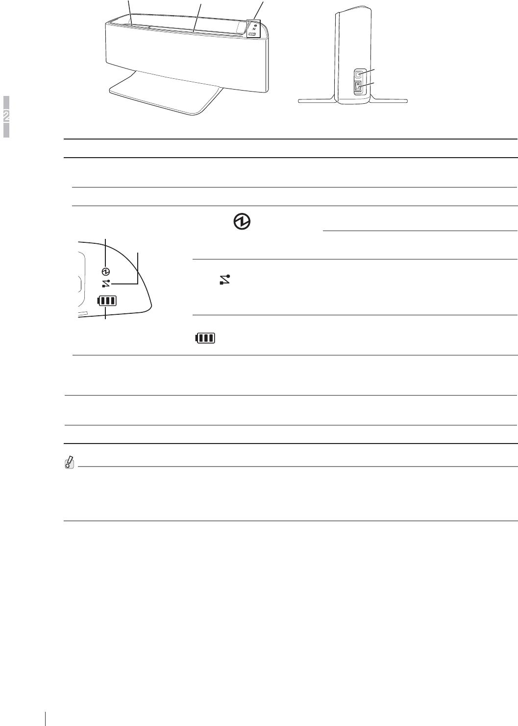
2-6
System Configuration (Product Overview)
2
FDR D-EVO
II Operation Manual 897N120339A
Ŷ DR-ID 1200DU
Docking stand (DR-ID 1200DS)
Flat panel sensor
identification lamp READY lamp Status lamps
Mute switch
Main switch
<right side>
Name Description
Docking stand
(DR-ID 1200DS)
6XSSOLHVWKHSRZHUWRWKHÀDWSDQHOVHQVRUDQGFRQQHFWVWKHÀDWSDQHOVHQVRU
and the image processing unit.
Main switch 6XSSOLHVWKHSRZHUWRWKHGRFNLQJVWDQGDQGWKHÀDWSDQHOVHQVRU
Status lamps
LINK
POWER
Battery pack level indicator
POWER (Blue)
(The power on/off state of the
docking stand is displayed.).
On Power ON
Off Power OFF
LINK (White) On
Connected
(This lamp is lit when
communication with the control
cabinet is established after
LQVHUWLQJWKHÀDWSDQHOVHQVRU
Battery pack level indicator
Indicates the charge level of the battery pack for
WKHÀDWSDQHOVHQVRULQ\HOORZLVKJUHHQ
Lights in orange when an error occurs.
Mute switch This switch is used to mute the buzzer that sounds when an exposure is ready,
DÀDWSDQHOVHQVRULVLQVHUWHGRUWKHEDWWHU\SDFNRIDÀDWSDQHOVHQVRULVIXOO\
charged.
Flat panel sensor
LGHQWL¿FDWLRQODPS
7KLVODPSLVOLWLQWKHVDPHFRORUDVWKHÀDWSDQHOVHQVRULGHQWL¿FDWLRQODPSRQ
WKHÀDWSDQHOVHQVRUFXUUHQWO\LQXVH
READY lamp (Green) 7KLVODPSLVOLWZKHQWKHÀDWSDQHOVHQVRUFXUUHQWO\LQXVHLVUHDG\IRUH[SRVXUH
1RWHWKDWWKHÀDWSDQHOVHQVRULQVHUWHGLQWRWKHGRFNLQJVWDQGFDQRQO\EHFKDUJHGRUXVHGIRUFRPPXQLFDWLRQ
It cannot be used for exposures.
• If the battery pack level indicator of the docking stand lights in orange, press the main switch to turn it off and
press the switch again to turn the power back on.
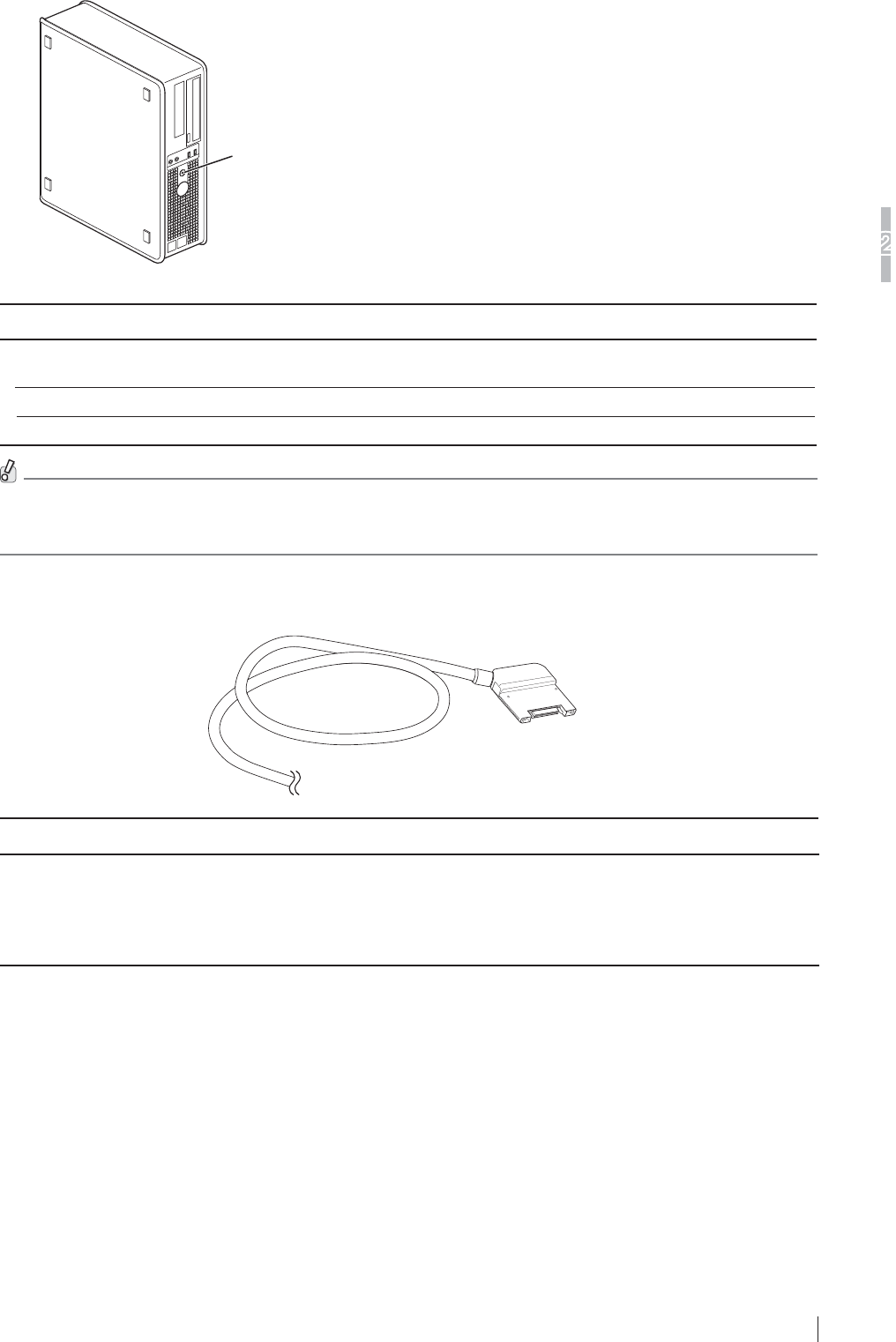
2-7
System Configuration (Product Overview)
2
FDR D-EVO
II Operation Manual 897N120339A
Ŷ DR-ID 1200MC
Main switch/
power status LED
Control cabinet (DR-ID 1200MC)
Name Description
Control cabinet
(DR-ID 1200MC)
$SHUVRQDOFRPSXWHUXVHGIRUFRQWUROOLQJWKHÀDWSDQHOVHQVRUDQG
performing image processing.
Main switch Supplies the power to the control cabinet.
Power status LED Displays ON/OFF of the control cabinet.
'HSHQGLQJRQWKHFRQ¿JXUDWLRQWKHFRQWUROFDELQHW'5,'0&PD\QRWEHLQFOXGHGLQWKHV\VWHP,IQRW
included, the software for the control cabinet can be installed on the image processing unit (DR-ID 300CL).
)RUGHWDLOVSHFL¿FDWLRQRILPDJHSURFHVVLQJXQLWSOHDVHUHIHUWR³'5,'&/2SHUDWLRQ0DQXDO´
Ŷ SE cable
Name Description
SE cable $FDEOHWKDWFRQQHFWVWKHÀDWSDQHOVHQVRUDQGWKHSRZHUVXSSO\XQLW
7KLVFDEOHLVXVHGIRUDGGLQJWKHVHFRQGDQGVXEVHTXHQWÀDWSDQHO
VHQVRUVFKDQJLQJRYHUWKHFRQQHFWLRQEHWZHHQWKHÀDWSDQHOVHQVRUVDQG
other usages.
&DEOHOHQJWK$SSUR[PIW$SSUR[PIW
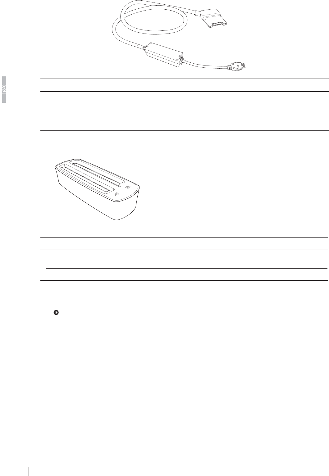
2-8
System Configuration (Product Overview)
2
FDR D-EVO
II Operation Manual 897N120339A
Ŷ SE communication cable
Name Description
SE communication cable $FDEOHXVHGIRUFRQQHFWLQJWKHÀDWSDQHOVHQVRUDQGWKHRSWLRQDODFFHVVSRLQW
This cable is used for wired communication if wireless communication is not
available.
,QDGGLWLRQWKLVFDEOHLVXVHGIRUUHJLVWHULQJRUUHFRJQL]LQJWKHÀDWSDQHOVHQVRU
&DEOHOHQJWK$SSUR[PIW
Ŷ %DWWHU\FKDUJHU2SWLRQDO
Battery charger
Name Description
Battery charger &KDUJHVWKHEDWWHU\SDFNIRUWKHÀDWSDQHOVHQVRU7ZRSDFNVFDQEH
charged at the same time.
Charge status indicator LED Indicates charge status.
Ŷ ,PDJHSURFHVVLQJXQLW
For the unit names and functions of the image processing unit, see the “DR-ID 300CL Operation
Manual”.
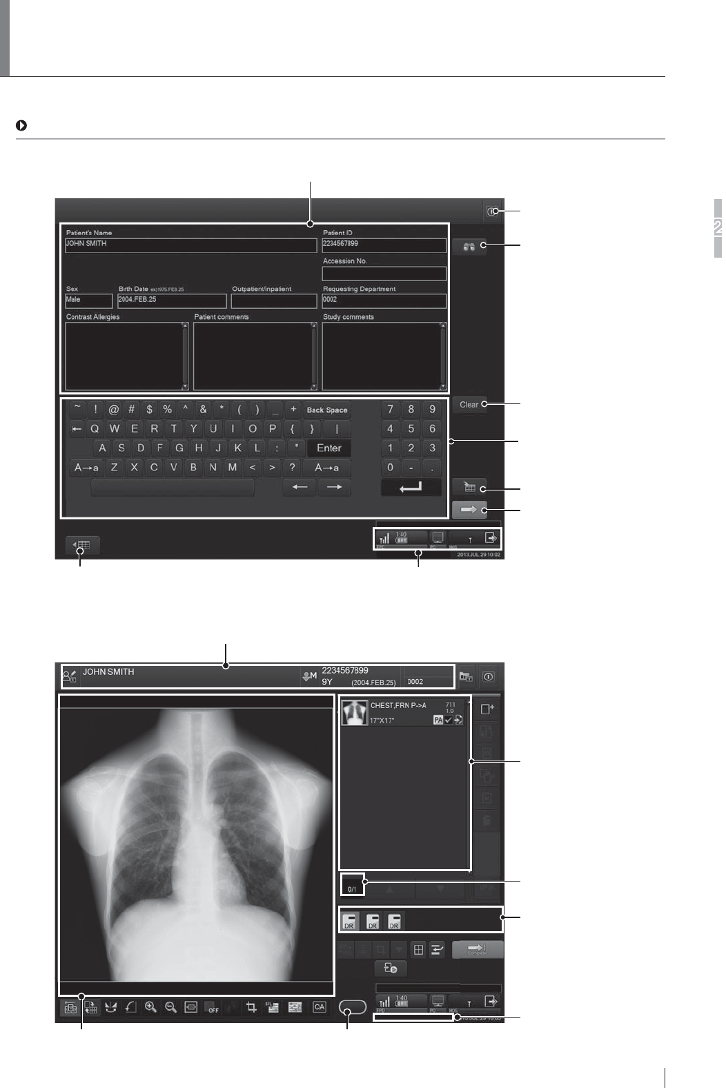
2-9
6\VWHP&RQILJXUDWLRQ3URGXFW2YHUYLHZ
2
FDR D-EVO
II Operation Manual 897N120339A
,PDJH3URFHVVLQJ8QLW'LVSOD\
&RQILJXUDWLRQ
When the self-initialization process ends, the Patient Information Input Screen will appear on the image
processing unit display.
For details, see “DR-ID 300CL Operation Manual”.
Ŷ Patient Information Input Screen
Patient information input field
Input patient information.
Clears patient information
(except for technologist).
Operates the Patient Information
Database function to input patient
information.
Tool button
Displays the “Study List screen”.
Screen keyboard
Used to input characters in the
patient information input field.
Reserves a study.
Terminates patient information
input, and proceeds to exposure
menu selection.
Connected devices status
Connected devices status display field. Displays the status of connected devices.
For details, see the next page.
Ŷ Study Screen
Patient information display field
Displays patient information.
Exposure menu list
This list shows exposure
menus selected on the
“Exposure Menu Selection
screen”.
Exposure unit display field
The Tube, Technique, and
Imaging panels can be uniquely
arranged and displayed.
Selected exposure menu
number display field
Technologist display field
Displays the name of logged-
in technologist (user).
Image display field
The read image appears.
Shot Ready (exposure ready status indicator)
Exposure (image reading) can be performed when the indicator is lit green.
Exposure (image reading) cannot be performed when the indicator is not lit.
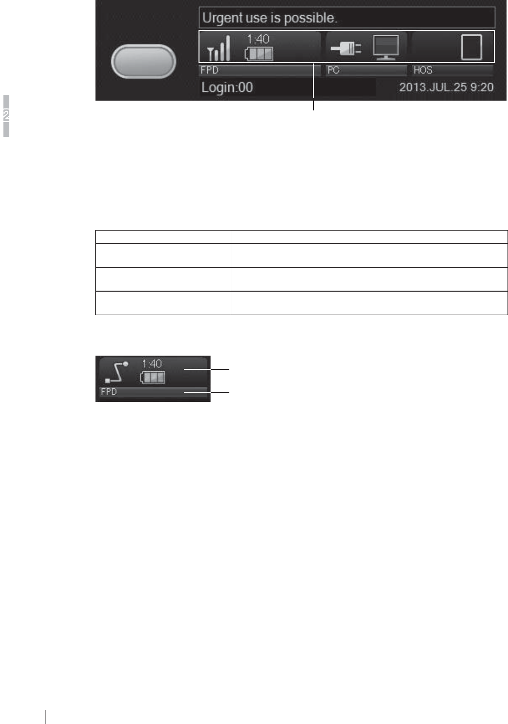
2-10
System Configuration (Product Overview)
2
FDR D-EVO
II Operation Manual 897N120339A
Ŷ Connected Devices Status
Details on each icon and its display area are described below.
Other indicator icons display area
Other indicator icons display area
7KHVWDWXVRIWKHÀDWSDQHOVHQVRUSRZHUVXSSO\XQLWGRFNLQJVWDQGDQGLPDJHSURFHVVLQJXQLW
is shown with an icon. Up to six icons can be displayed. The status of each connected device is
shown in three categories.
Device information displayed in each category is as follows.
Category Device information
Status of exposure unit (1) Exposure unit communication indicator
(2) Exposure unit battery indicator
Status of the image processing
unit and personal computer
(3) Console event indicator
(4) Console battery indicator
Other (Status of output unit,
hospital LAN, etc.)
(5) Output status indicator
(6) Hospital wireless communication indicator
The information is displayed in each category as shown below.
Device information of the category
Category
Locations of category information can be customized in the user utility. For details, see “DR-ID
300CL Reference Guide”.
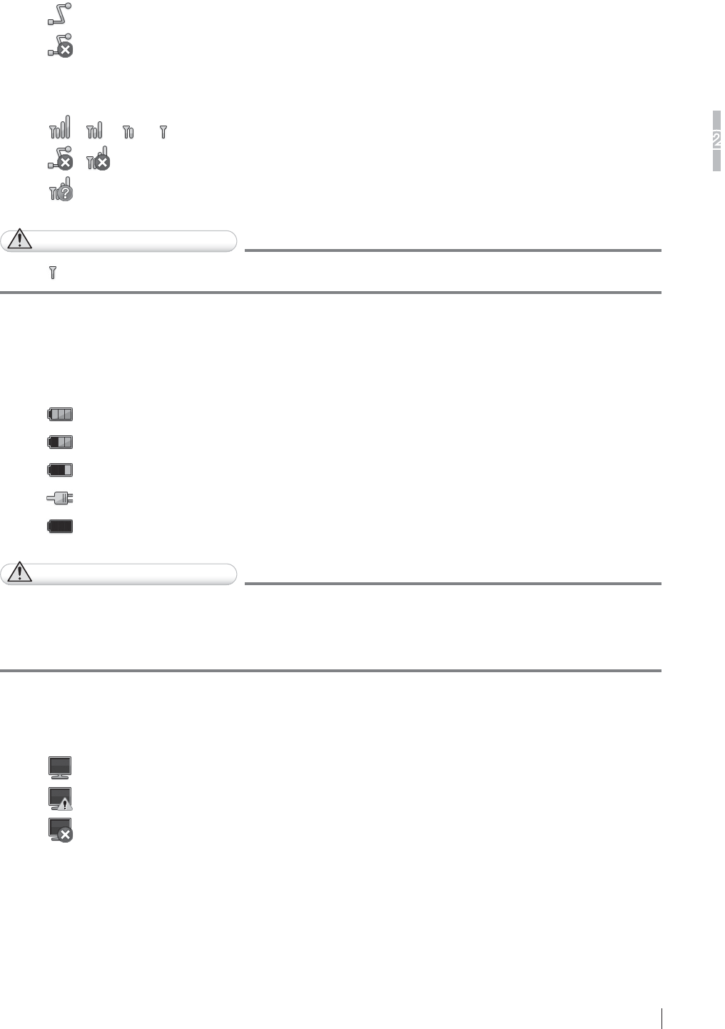
2-11
6\VWHP&RQILJXUDWLRQ3URGXFW2YHUYLHZ
2
FDR D-EVO
II Operation Manual 897N120339A
(1) Exposure Unit Communication Indicator
7KHIROORZLQJLFRQVGLVSOD\FRPPXQLFDWLRQVWDWXVRIWKHÀDWSDQHOVHQVRUFRUUHVSRQGLQJWRWKH
VHOHFWRUVHOHFWHGLQWKHH[SRVXUHXQLWGLVSOD\¿HOGRIWKH³6WXG\VFUHHQ´
,IWKHÀDWSDQHOVHQVRULVFRQQHFWHGZLWKZLUHGFRPPXQLFDWLRQWKHIROORZLQJLFRQVDUHGLVSOD\HG
&RQQHFWHG
8QNQRZQ
,IWKHÀDWSDQHOVHQVRULVFRQQHFWHGZLUHOHVVO\WKHIROORZLQJLFRQVDUHGLVSOD\HG
/ / / &RQQHFWHG'LVSOD\VWKHVLJQDOVWUHQJWKLQIRXUOHYHOV
/ 'LVFRQQHFWHG
8QNQRZQ
CAUTIONS
While LVGLVSOD\HGUDGLRJUDSK\LVQRWUHFRPPHQGHGVLQFHZLUHOHVVFRPPXQLFDWLRQLVXQVWDEOH
(2) Exposure Unit Battery Indicator
When the exposure unit is connected to the image processing unit, the battery status is indicated
with the following icons.
5HDG\IRUH[SRVXUHEDWWHU\FKDUJHIXOO\FKDUJHG
5HDG\IRUH[SRVXUHH[SRVXUHWLPHDYDLODEOHOHVVWKDQRQHKRXU
5HDG\IRUH[SRVXUHEDWWHU\FKDUJHUHFKDUJHQHHGHG
5HDG\IRUH[SRVXUHFRQQHFWHGWRSRZHUVXSSO\
1RWUHDG\IRUH[SRVXUH
CAUTIONS
:KHQDQH[SRVXUHLVUHDG\WREHPDGHWKH5($'<VWDWXVODPSRQWKHÀDWSDQHOVHQVRULVOLW
JUHHQWKHSRZHUFRQVXPSWLRQRIWKHÀDWSDQHOVHQVRULQFUHDVHV$OWKRXJKWKHLQGLFDWRULFRQRI
WKHUHPDLQLQJEDWWHU\OHYHOFKDQJHVWRORZDQGWKHYDOXHRIWKHRSHUDEOHWLPHGLVSOD\GHFUHDVHV
temporarily, these are not failures.
(3) Console Event Indicator
The following icons display the status of the image processing unit.
1RUPDO
:DUQLQJOHYHOHYHQWRQJRLQJ
(UURUOHYHOHYHQWRQJRLQJ
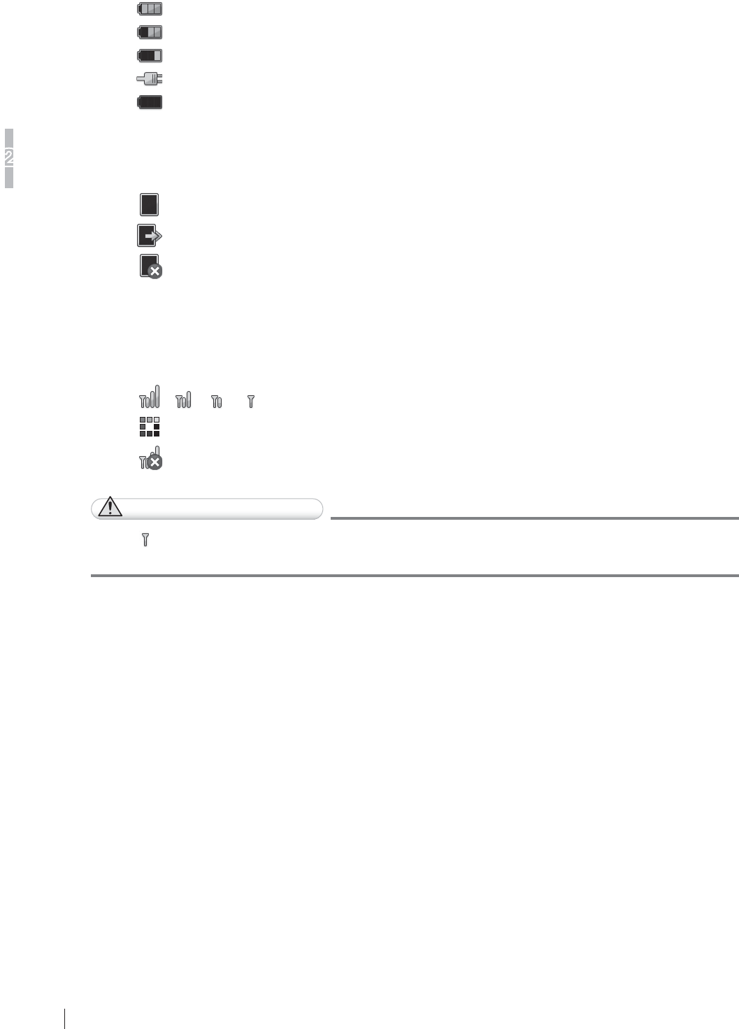
2-12
6\VWHP&RQILJXUDWLRQ3URGXFW2YHUYLHZ
2
FDR D-EVO
II Operation Manual 897N120339A
(4) Console Battery Indicator
The status of the PC battery and of PC connection to the AC adapter are shown by the icons
below.
5HDG\IRUXVH
5HDG\IRUXVH
5HDG\IRUXVHEDWWHU\FKDUJHUHFKDUJHQHHGHG
5HDG\IRUXVHFKDUJLQJRUWKH$&DGDSWHUFRQQHFWHG
1RWUHDG\IRUXVH
(5) Output Status Indicator
The following icons display the output status.
:DLWLQJIRULPDJHRXWSXW
3URFHVVLQJLPDJHRXWSXW
2XWSXWHUURU
(6) Hospital Wireless Communication Indicator
The status of wireless communication between the image processing unit and the hospital LAN is
shown by the icons below.
/ / / &RQQHFWHG5DGLR¿HOGVWUHQJWKLVGLVSOD\HGLQIRXUOHYHOV
6ZLWFKLQJFRQQHFWLRQ
'LVFRQQHFWHG
CAUTIONS
While LV GLVSOD\HG LPDJH WUDQVIHU WR WKH KRVSLWDO /$1 EHFRPHV XQVWDEOH DOWKRXJK ZLUHOHVV
communication is established.
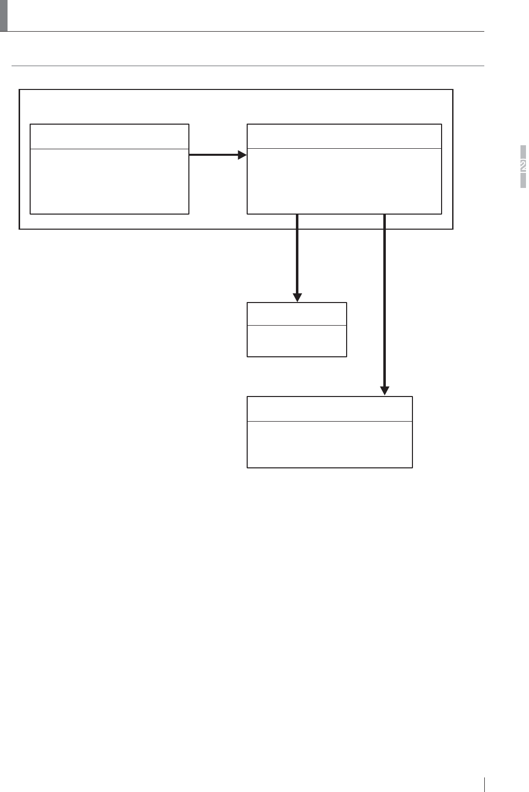
2-13
System Configuration (Product Overview)
2
FDR D-EVO
II Operation Manual 897N120339A
5RXWLQH2SHUDWLRQ'LDJUDP
7KHV\VWHPFRQ¿JXUDWLRQDQGWKHURXWLQHRSHUDWLRQGLDJUDPIRUWKH)'5'(92II is as follows.
Image data
Image data
Imager
• Film output
Image Management Workstation
• DICOM-conformed
open network supported
Image Processing Unit
• Patient information entry
• Exposure region / study menu selection
• Image processing, etc.
Image data
DR-ID 1200PU/DR-ID 1200DU
DR-ID 1200PU/DR-ID 1200DU
FDR D-EVO2 (DR-ID 1200)
• X-ray exposure
• Image reading

2-14
System Configuration (Product Overview)
2
FDR D-EVO
II Operation Manual 897N120339A
2.5 Wireless Specifications
7HFKQLFDO6SHFL¿FDWLRQ
IEEE802.11n (protocol) , 2.4GHz, W52, W53, W56, W58 (frequency)
,QWHQGHGHQYLURQPHQW5RRPVL]HRIP[P[PIW[IW[IWKHLJKWRU
less (general X-ray room)
(The electric shield does not exist excluding the installation stand or
bed.)
,QVWDOODWLRQ'RQRWSODFHGHYLFHVJHQHUDWLQJHOHFWURPDJQHWLFZDYH&705,GLDWKHUP\
RFID etc.) near this equipment.
We recommend not to use any other wireless devices such as cellular/smart
phones, portable phones, microwave ovens, WAPs, etc. within 2m (6.6 ft) of
the wireless FDR D-EVO II system.
When other wireless devices are used within 2m (6.6 ft), wireless data
communication may be delayed.
(Data will not be lost; if a timeout occurs a retry can be performed after the
cause of interference has been removed)
Do not cover the Flat Panel Sensor (DR-ID 1201SE/DR-ID 1202SE/DR-ID
1211SE/DR-ID 1212SE) with a shield such as a metallic plate as this will
interfere with a wireless communication.
,QIRUPDWLRQEHLQJWUDQVPLWWHG6\VWHP&RQWURO6LJQDO,PJBUHTB&0'HWF
Image Data of the Flat Panel Sensor
1RWH3DWLHQW,QIRUPDWLRQLVQRWWUDQVPLWWHGE\ZLUHOHVV
interface of Access point
:LUHOHVVUDQJHPD[PIWIURPWKH$FFHVVSRLQWDVWHVWHG$FWXDOUDQJHPD\YDU\
'DWDWUDQVIHUUDWH0ESV'5,'EHWZHHQWKH)ODW3DQHO6HQVRUDQG&RQVROH3&
(This value is FUJIFILM measuring result of wireless module, and
actual data rate may vary.)
7UDQVIHU3RZHUG%PRUOHVV
0RGXODWLRQ2)'03URYLGHGE\,(((Q
:LUHOHVV'DWD6HFXULW\:LUHOHVV)'5'(92II system (DR-ID 1201SE/DR-ID 1202SE/
DR-ID 1211SE/DR-ID 1212SE) will be utilizing the IEEE 802.11n.
The Wireless Access Point (WAP) has a feature that limits the
maximum number of the Flat Panel Sensor per access point to
ensure data integrity. Further the WAP has MAC Address Filtering
(unique IP address) and Wireless LAN Segmentation to ensure
handshaking with only the registered wireless FDR D-EVO II Flat
Panel Sensors (DR-ID 1201SE/DR-ID 1202SE/DR-ID 1211SE/
DR-ID 1212SE).
,QDGGLWLRQWRWKH0$&DGGUHVV¿OWHULQJWKHZLUHOHVV
communication between DR-ID 1201SE/DR-ID 1202SE/DR-ID
1211SE/DR-ID 1212SE (Flat Panel Sensor) and access point is
secured by WPA2-PSK encryption with AES (Advanced Encryption
Standard). Data security feature will be enabled during installation
E\D)8-,),/0¿HOGVHUYLFHHQJLQHHU1RSDWLHQWLQIRUPDWLRQ
is transmitted between DR-ID 1201SE/DR-ID 1202SE/DR-ID
1211SE/DR-ID 1212SE (Flat Panel Sensor) and access point.,
between access point and the console.
+DQGVKDNLQJ3DLULQJ7KH:LUHOHVV$FFHVV3RLQWDQG'5,'6('5,'6('5
ID 1211SE/DR-ID 1212SE (Flat Panel Sensor) will be paired during
LQVWDOODWLRQE\D)8-,),/0¿HOGVHUYLFHHQJLQHHUWRHQVXUHRQHWRRQH
ZLUHOHVVFRQQHFWLRQ)8-,),/0¿HOGVHUYLFHHQJLQHHUZLOOPHDVXUH
the wireless transmission condition in the primary area, so the FDR
D-EVO II system can be used stable.
)UHTXHQF\7ROHUDQFHSSP

2-15
System Configuration (Product Overview)
2
FDR D-EVO
II Operation Manual 897N120339A
Quality of Service (QoS)
Item Standard
DR-ID 1201SE/DR-ID 1202SE/
DR-ID 1211SE/DR-ID 1212SE
Unit Remarks
Form of electric
wave Spectrum diffusion
Center frequency HT20 5180 - 5825
2412 - 2472
MHz 36ch,40ch,44ch,48ch
HT40 5190 - 5795
2422 - 2462
MHz 38ch,46ch
W52
Channel interval IEEE802.11n 20(HT20) / 40(HT40) -
Transmission rate IEEE802.11n HT20䠖MCS0-15
HT40䠖MCS0-15
-
Modulation OFDM
Output power Power
Max 17
Frequency
Tolerance
- 20 ~ +20 ppm MAX
Reception
sensitivity
PER :
Packet Error
Rate <10%
IEEE 802.11n
(5GHz)
MCS0=-89 dBm
HT20
MCS1=-86 dBm
MCS2=-83 dBm
MCS0=-86 dBm
HT40
MCS1=-83 dBm
MCS2=-80 dBm
IEEE 802.11n
(2.4GHz)
MCS0=-88 dBm
HT20
MCS1=-85 dBm
MCS2=-82 dBm
MCS0=-85 dBm
HT40
MCS1=-82 dBm
MCS2=-79 dBm
dBm
W52
)RUGHWDLOVRQWKHZLUHOHVVVSHFL¿FDWLRQRIWKHLPDJHSURFHVVLQJXQLWVHHWKH³&RQVROH$GYDQFH'5,'&/
Operation Manual”.

2-16
System Configuration (Product Overview)
2
FDR D-EVO
II Operation Manual 897N120339A
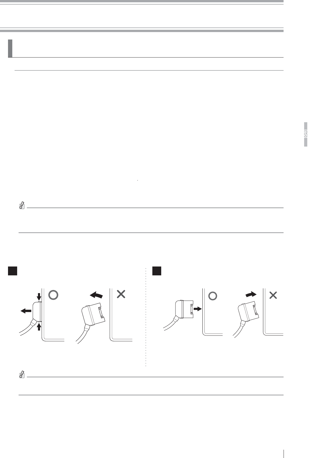
3-1
Basic Operation
3
FDR D-EVO
II Operation Manual 897N120339A
Chapter 3 Basic Operation
3UHSDULQJWKH)ODW3DQHO6HQVRU
7KLVVHFWLRQGHVFULEHVKRZWRSUHSDUHWKHÀDWSDQHOVHQVRU
3.1.1 Type of Flat Panel Sensor
DR-ID 1201SE, DR-ID 1202SE, DR-ID 1211SE, DR-ID 1212SE
7KHEDWWHU\SDFNRSWLRQDOLVUHTXLUHGZKHQWKHÀDWSDQHOVHQVRULVXVHGLQZLUHOHVVFRPPXQLFDWLRQ
mode.
3.1.2 Number of the Connectable Flat Panel Sensors
7RHQDEOHWKHÀDWSDQHOVHQVRULWV,'QHHGVWREHUHJLVWHUHGLQDGYDQFHE\RXURI¿FLDOGHDOHURU
FUJIFILM Representative.
8SWRDKXQGUHGÀDWSDQHOVHQVRUVFDQEHUHJLVWHUHG
8SWR¿YHÀDWSDQHOVHQVRUVFDQEHFRQQHFWHG
:KHQWKH'5,'38LVXVHGXSWRWZRÀDWSDQHOVHQVRUVFDQEHFRQQHFWHGWRRQHSRZHU
supply unit in wired communication mode. Up to two power supply unit can be used.
:KHQWKH'5,''8LVXVHGRQO\RQHÀDWSDQHOVHQVRUVFDQEHFRQQHFWHGWRRQHGRFNLQJ
stand in wired communication mode. Up to three docking stand can be used.
'HSHQGLQJRQWKHFRQ¿JXUDWLRQWKHFRQWUROFDELQHW'5,'0&PD\QRWEHLQFOXGHGLQWKHV\VWHP,IQRW
included, the software for the control cabinet can be installed on the image processing unit (DR-ID 300CL).
)RUGHWDLOVSHFL¿FDWLRQRILPDJHSURFHVVLQJXQLWSOHDVHUHIHUWR³'5,'&/2SHUDWLRQ0DQXDO´
&RQQHFWLQJ'LVFRQQHFWLQJWKH)ODW3DQHO6HQVRU
Connector
1 Disconnect the connector.
Press the latches on both sides of the connector.
2 Connect the connector.
Press the connector into the insertion section.
Make sure that the latches on both sides are
properly engaged when connecting the connector.
If the connector is inserted incompletely, the power
may turn off.
:KHQPXOWLSOHÀDWSDQHOVHQVRUVDUHXVHGPDNHVXUHWKDWWKH5($'<ODPSDPRQJWKHVWDWXVODPSVRIWKHÀDW
panel sensor to be used for an exposure is lit.
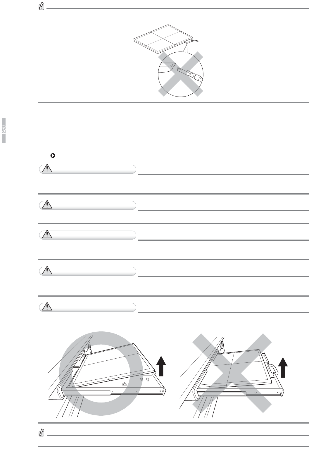
3-2
Basic Operation
3
FDR D-EVO
II Operation Manual 897N120339A
,QVHUWLQJ5HPRYLQJWKH)ODW3DQHO6HQVRULQWRIURPWKH
5DGLRJUDSKLF([DPLQDWLRQ6WDQG
)ROORZWKHSURFHGXUHEHORZWRLQVHUWUHPRYHWKHÀDWSDQHOVHQVRULQWRIURPWKHUDGLRJUDSKLF
examination stand.
For details, see the Operation Manual for the radiographic examination stand.
CAUTIONS
)RUWKHSRVLWLRQLQJDWWKHWLPHRILQVHUWLQJUHPRYLQJWKHÀDWSDQHOVHQVRUVHHWKH2SHUDWLRQ
0DQXDOIRUWKHUDGLRJUDSKLFH[DPLQDWLRQVWDQG
CAUTIONS
0DNHVXUHWKDWWKHÀDWSDQHOVHQVRULVLQVWDOOHGLQWKHUDGLRJUDSKLFH[DPLQDWLRQVWDQGVHFXUHO\
CAUTIONS
%HFDUHIXOQRWWRKDYH\RXU¿QJHUVFDXJKWZKHQLQVHUWLQJUHPRYLQJWKHÀDWSDQHOVHQVRULQWR
IURPWKHUDGLRJUDSKLFH[DPLQDWLRQVWDQG
CAUTIONS
:KHQSXOOLQJRXWSXVKLQJLQWKHWUD\RIWKHUDGLRJUDSKLFH[DPLQDWLRQVWDQGDIWHUVHWWLQJWKHÀDW
SDQHOVHQVRURQLWEHFDUHIXOQRWWRGURSWKHÀDWSDQHOVHQVRURUGDPDJHWKHWUD\
CAUTIONS
%HIRUHLQVHUWLQJUHPRYLQJWKHÀDWSDQHOVHQVRULQWRIURPWKHUDGLRJUDSKLFH[DPLQDWLRQVWDQG
SXOORXWWKHWUD\FRPSOHWHO\2WKHUZLVHWKHÀDWSDQHOVHQVRUPD\EHGDPDJHG
)RUWKHHIIHFWLYHDUHDRIWKHÀDWSDQHOVHQVRUVHHSDJH$
&RQQHFW'LVFRQQHFWWKHFRQQHFWRUVWUDLJKWWRWKHÀDWSDQHOVHQVRU,IFRQQHFWHGGLVFRQQHFWHGDWDQDQJOHWKH
connector may be damaged.
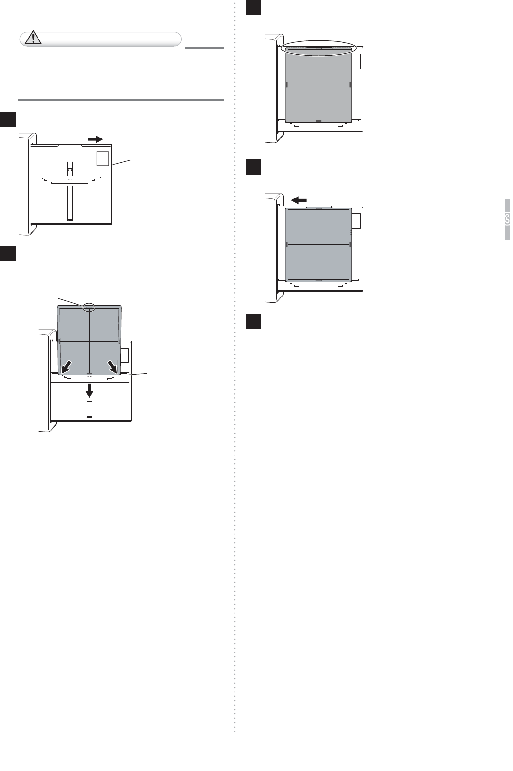
3-3
Basic Operation
3
FDR D-EVO
II Operation Manual 897N120339A
>@8SULJKWW\SH
CAUTIONS
:KHQLQVHUWLQJWKHÀDWSDQHOVHQVRULQWR
WKHUDGLRJUDSKLFH[DPLQDWLRQVWDQGGLUHFW
WKHH[SRVXUHSODQHWRZDUGWKH;UD\WXEH
1 Pull out the tray.
Tray
2
,QVHUWWKHÀDWSDQHOVHQVRULQWRWKHFDVVHWWH
UHFHLYHZLWKWKHJUHHQPDUNRIWKHÀDWSDQHO
sensor up, and then move it downwards.
Cassette receive
Green mark
3 6HWWKHÀDWSDQHOVHQVRUWRWKHXSSHUSDUWRI
the tray.
4 3XVKWKHWUD\EDFNLQWRSODFHDIWHUVHWWLQJ
WKHÀDWSDQHOVHQVRU
5 5HPRYHWKHÀDWSDQHOVHQVRUDIWHUXVH
Pull out the tray, push the cassette receive
GRZQZDUGVDQGWKHQUHPRYHWKHÀDWSDQHOVHQVRU
Push the tray back into place.
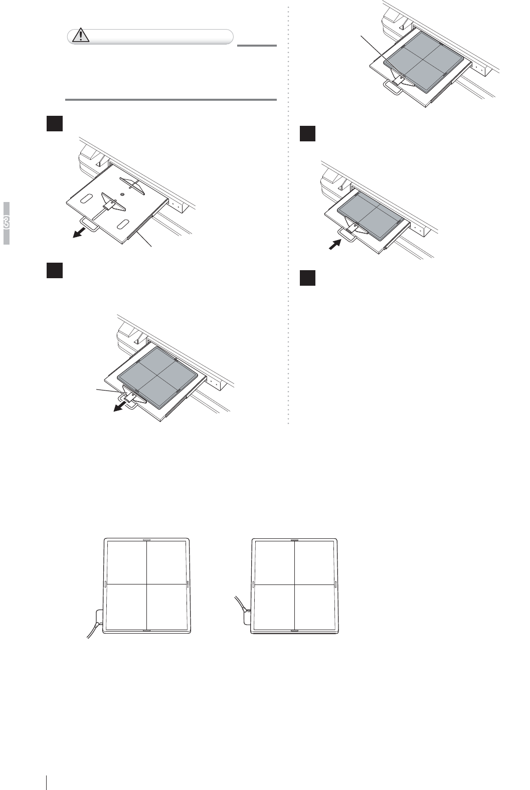
3-4
Basic Operation
3
FDR D-EVO
II Operation Manual 897N120339A
[2] Bed type
CAUTIONS
:KHQLQVHUWLQJWKHÀDWSDQHOVHQVRU
WRWKHUDGLRJUDSKLFH[DPLQDWLRQVWDQG
direct the exposure plane upwards.
1 3XOORXWWKHWUD\E\XVLQJWKHKDQGOH
Tray
2 3XOOWKHFDVVHWWHVWRSSHUDQGVHWWKHÀDW
SDQHOVHQVRUVRWKDWLWVFHQWHUPDUNLV
DOLJQHGZLWKWKHFHQWHURIWKHVWRSSHU
Cassette
stopper
Center mark
3 3XVKWKHWUD\EDFNLQWRSODFHE\XVLQJWKH
KDQGOHDIWHUVHWWLQJWKHÀDWSDQHOVHQVRU
4 5HPRYHWKHÀDWSDQHOVHQVRUDIWHUXVH
Hold the handle and pull out the tray. Remove the
ÀDWSDQHOVHQVRUZKLOHSXOOLQJWKHFDVVHWWHVWRSSHU
and then push the tray back into place.
&KDQJLQJWKH'LUHFWLRQRIWKH)ODW3DQHO6HQVRU
Connector
7KHGLUHFWLRQRIWKHFRQQHFWRURIWKHÀDWSDQHOVHQVRUFDQEHFKDQJHGGHSHQGLQJRQKRZLWLV
inserted into the radiographic examination stand.
7RFKDQJHWKHGLUHFWLRQFRQWDFWRXURI¿FLDOGHDOHURU)8-,),/05HSUHVHQWDWLYH
When shipped After changing the direction
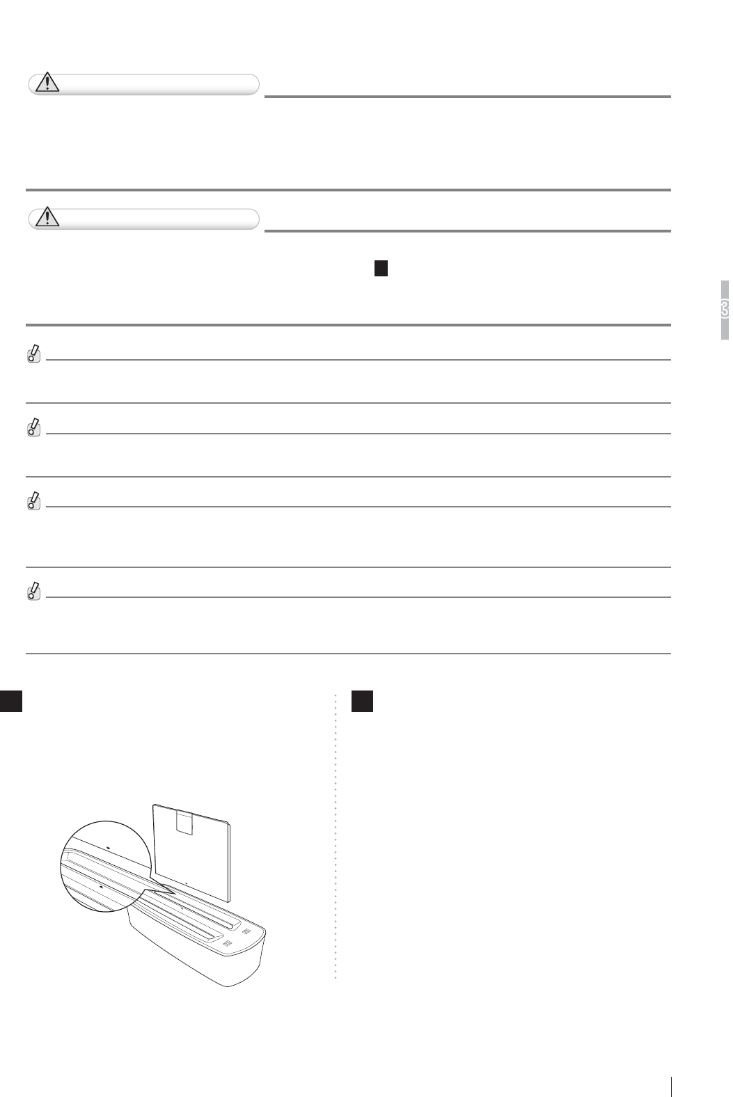
3-5
Basic Operation
3
FDR D-EVO
II Operation Manual 897N120339A
&KDUJLQJWKH%DWWHU\3DFNIRUWKH)ODW3DQHO6HQVRU
Charge the battery pack (optional) using the battery charger (optional).
CAUTIONS
'RQRWFKDUJHWKHEDWWHU\SDFNRWKHUWKDQWKRVHGHVLJQDWHGE\)8-,),/0&RUSRUDWLRQ,IWKH
EDWWHU\SDFNLVFKDUJHGXQGHUWKHFKDUJLQJFRQGLWLRQVYROWDJHFXUUHQWDQGFKDUJLQJPHWKRG
GLIIHUHQWIURPWKRVHVSHFL¿HGE\)8-,),/0&RUSRUDWLRQWKHEDWWHU\SDFNPD\HPLWVPRNH
LJQLWHH[SORGHRUOHDNÀXLG
CAUTIONS
:KHQVHWWLQJWKHEDWWHU\SDFNLQWRWKHEDWWHU\FKDUJHUPDNHVXUHWKDWWKHRULHQWDWLRQRIWKH
EDWWHU\SDFNLVFRUUHFWDVVKRZQLQWKH¿JXUHLQ6WHS
1
,IWKHEDWWHU\SDFNLVIRUFLEO\VHWLQ
WKHZURQJRULHQWDWLRQERWKWKHEDWWHU\SDFNDQGWKHEDWWHU\FKDUJHUPD\EHGDPDJHGDQGHPLW
VPRNHLJQLWHOHDNÀXLGRUFDXVHHOHFWULFVKRFN
:KHQWKHEDWWHU\SDFNLQVWDOOHGLQWKHÀDWSDQHOVHQVRULVIXOO\FKDUJHGLWLVSRVVLEOHWRSHUIRUPH[SRVXUHVIRUD
maximum of approximately 500 images. However, the number varies depending on the usage conditions.
7KHFDSDFLW\RIWKHEDWWHU\SDFNLVGLVSOD\HGRQWKHEDWWHU\SDFNOHYHOLQGLFDWRURIWKHÀDWSDQHOVHQVRUDQGRQWKH
screen of the image processing unit.
:KHQWKHUHPDLQLQJFDSDFLW\RIWKHEDWWHU\SDFNRIWKHÀDWSDQHOVHQVRUEHFRPHVOHVVWKDQDSSUR[PLQXWHV
a pop-up window appears on the image processing unit display, and exposure cannot be performed. If this
happens, replace or charge the battery pack.
:KHQWKHUHPDLQLQJFDSDFLW\RIWKHEDWWHU\SDFNLQVWDOOHGLQWKHÀDWSDQHOVHQVRUEHFRPHVORZWKHEDWWHU\SDFN
OHYHOLQGLFDWRULVOLWLQRUDQJHDQGH[SRVXUHVFDQQRWEHSHUIRUPHG,IWKLVKDSSHQVFRQQHFWWKH6(FDEOHWRWKHÀDW
panel sensor to charge the battery pack.
1 6HWWKHEDWWHU\SDFNLQWKHEDWWHU\FKDUJHU
When the battery pack is set, a buzzer sound is
generated and the charge status indicator LED
lights.
Two battery packs can be charged at the same time.
2 :KHQEDWWHU\FKDUJHLVFRPSOHWHGUHPRYH
WKHEDWWHU\SDFN
When battery charge is completed, the charge status
indicator LED changes from blinking to lighting.
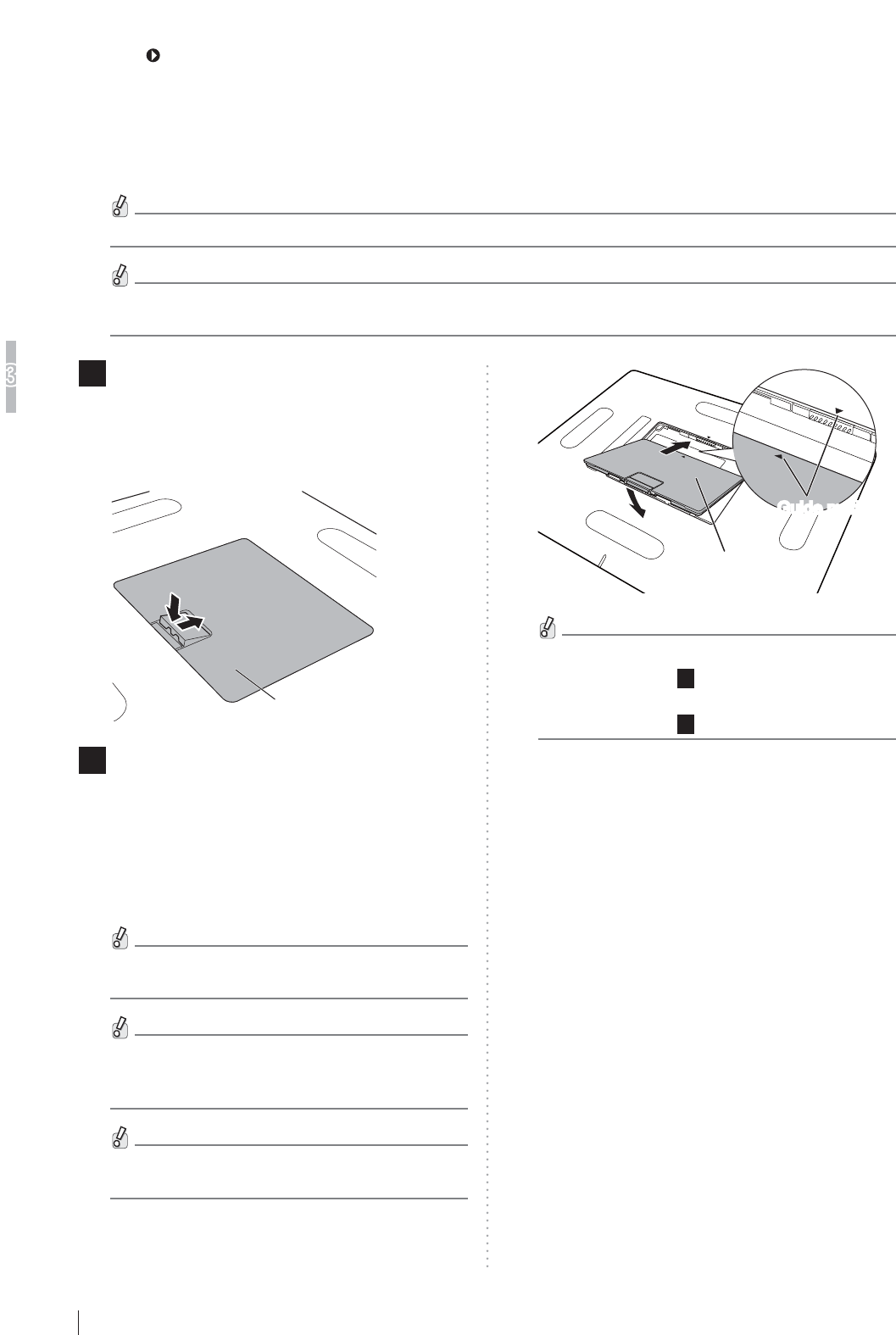
3-6
Basic Operation
3
FDR D-EVO
II Operation Manual 897N120339A
3.1.7
&KDUJLQJWKH,PDJH3URFHVVLQJ8QLW
For details, refer to the manual of the personal computer.
,QVWDOOLQJ5HPRYLQJWKH%DWWHU\3DFNIRUWKH)ODW3DQHO
Sensor
)ROORZWKHSURFHGXUHEHORZWRLQVWDOOUHPRYHWKHEDWWHU\SDFNIRUWKHÀDWSDQHOVHQVRU
:KHQLQVWDOOLQJUHPRYLQJWKHEDWWHU\SDFNSODFHWKHÀDWSDQHOVHQVRURQDÀDWSODFH
Do not remove the battery pack until a processed image appears in the window of the image processing unit after
the exposure.
1 Remove the battery cover.
3ODFHWKHÀDWSDQHOVHQVRUZLWKWKHEDFNVLGHIDFLQJ
XSZDUGSUHVVWKH³Ɣ´SRUWLRQRIWKHORFNOHYHUDQG
then slide it in the direction of the arrow to remove
the battery cover.
Battery pack
2 ,QVWDOOWKHEDWWHU\SDFN
Slide the battery pack along the dent of the battery
VHFWLRQRIWKHÀDWSDQHOVHQVRUWRZDUGWKHFRQQHFWRU
terminal. Align the guide mark of the battery pack
ZLWKWKDWRIWKHÀDWSDQHOVHQVRUDQGSXVKWKH
battery pack in to install it.
Make sure that battery pack is securely installed.
Pushing the battery pack in with the guide marks
misaligned may damage the connector terminal.
When attaching the battery pack, make sure that
the waterproof packing attached to the connector
WHUPLQDORIWKHÀDWSDQHOVHQVRULVDOLJQHGSURSHUO\
:KHQWKHEDWWHU\SDFNLVLQVWDOOHGLQWKHÀDWSDQHO
sensor, the power is automatically turned on.
Battery pack
Guide marksGuide marks
•
To remove the battery pack, perform the same
procedure as Step
1
(removing the battery cover).
•
To install the battery cover, perform the same
procedure as Step
2
(installing the battery pack).

3-7
Basic Operation
3
FDR D-EVO
II Operation Manual 897N120339A
/DPS,QGLFDWLRQVRQWKH)ODW3DQHO6HQVRU
7KLVVHFWLRQH[SODLQVWKHLQGLFDWLRQVRIWKHÀDWSDQHOVHQVRULGHQWL¿FDWLRQODPSDQGWKHEDWWHU\SDFN
level indicator. For other lamp indications, see “2.2.1 DR-ID 1200”.
Ŷ)ODWSDQHOVHQVRULGHQWL¿FDWLRQODPS
7KHÀDWSDQHOVHQVRULVDFWLYH %OLQNLQJLQZKLWH
While in sleep/extra sleep mode %OLQNLQJLQLGHQWL¿FDWLRQFRORU
While detecting an impact %OLQNLQJLQUHG
Ŷ %DWWHU\SDFNOHYHOLQGLFDWRU
(When the battery pack is being charged)
Fully charged /('/LWLQJUHHQ
$YDLODEOHWLPHPLQXWHVRUPRUH /('%OLQNLQJLQJUHHQ/('/LWLQJUHHQ
$YDLODEOHWLPHPLQXWHVRUPRUHEXWOHVVWKDQPLQXWHV /('%OLQNLQJLQJUHHQ/('/LWLQJUHHQ
$YDLODEOHWLPH/HVVWKDQPLQXWHV /('%OLQNLQJLQJUHHQ
(When the battery pack is not charged)
$YDLODEOHWLPHPLQXWHVRUPRUH /('/LWLQJUHHQ
$YDLODEOHWLPHPLQXWHVRUPRUHEXWOHVVWKDQPLQXWHV /('/LWLQJUHHQ
$YDLODEOHWLPH/HVVWKDQPLQXWHV /('/LWLQJUHHQ
$YDLODEOHWLPHPLQXWHVRUOHVV /('/LWLQRUDQJH
LED3 LED2 LED1
LED0
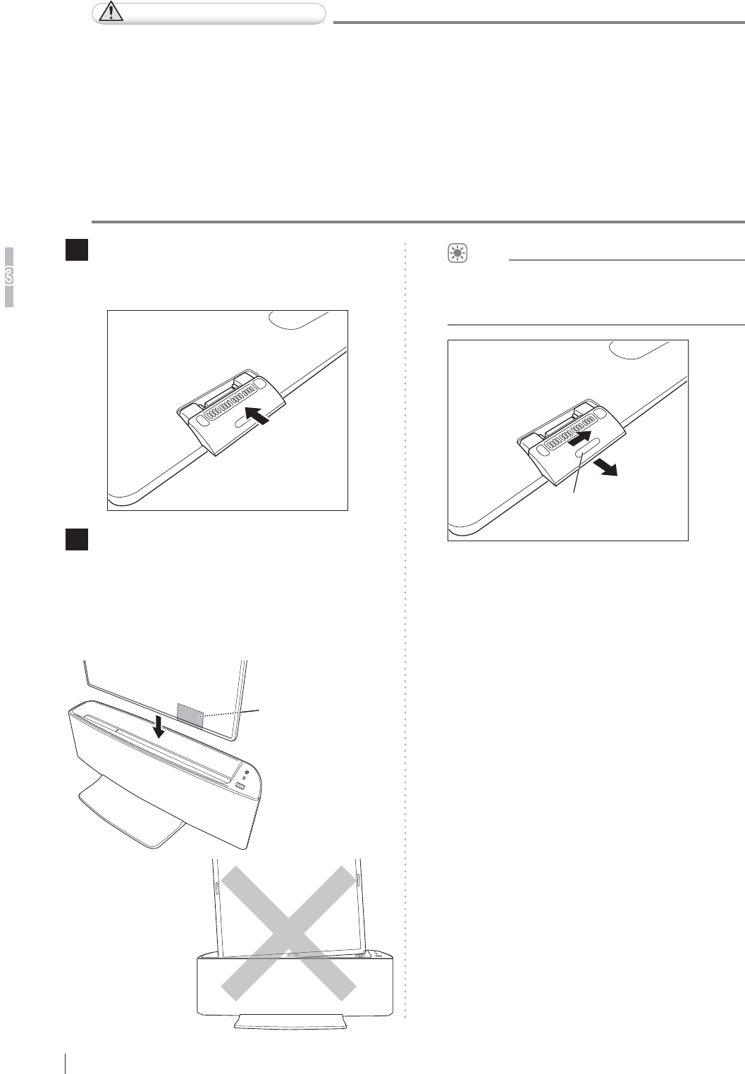
3-8
Basic Operation
3
FDR D-EVO
II Operation Manual 897N120339A
$WWDFKLQJWKH)ODW3DQHO6HQVRUWRWKH'RFNLQJ6WDQG
CAUTIONS
Ɣ +DQGOHWKHGRFNLQJVWDQGFDUHIXOO\'RQRWKLWRUGURSWKHGRFNLQJVWDQGRUVXEMHFWLWWR
VHYHUHVKRFNWRDYRLGSRVVLEOHGDPDJH
Ɣ ,IDQ\GDPDJHVXFKDVFUDFNLQJFKLSSLQJRUSHHOLQJLVIRXQGRQWKHGRFNLQJVWDQGXVHLW
after repair. Otherwise, personal injury may result. Consult a FUJIFILM dealer for repair.
Ɣ ,IH[FHVVLYHIRUFHLVDSSOLHGWRWKHGRFNLQJVWDQGLWPD\EHGDPDJHG,QDGGLWLRQGRQRW
DSSO\H[FHVVLYHIRUFHWRWKHÀDWSDQHOVHQVRULQVHUWHGLQWKHGRFNLQJVWDQG
Ɣ :KHQPRYLQJWKHGRFNLQJVWDQGWKDWKDVDOUHDG\EHHQLQVWDOOHGFRQVXOWRXURI¿FLDOGHDOHU
or local representative.
Ɣ 'RQRWSXOOWKHFDEOHIRUFLEO\2WKHUZLVHWKHFDEOHPD\EHEURNHQRUWKHGRFNLQJVWDQGPD\
EHGDPDJHG
1 'LVFRQQHFWWKHFRQQHFWRUIURPWKHÀDW
panel sensor and then attach the adapter for
WKHGRFNLQJVWDQG
2 ,QVHUWWKHÀDWSDQHOVHQVRU
Check the position of the adapter for the docking
VWDQGDOLJQWKHÀDWSDQHOVHQVRUZLWKWKHGRFNLQJ
VWDQGDQGVORZO\LQVHUWWKHÀDWSDQHOVHQVRUVWUDLJKW
into the docking stand until it stops along the right
and left guides of the docking stand.
Adapter for the
docking stand
HINT
When removing the adapter for the docking stand
IURPWKHÀDWSDQHOVHQVRUVOLGHWKHORFNNH\RQWKH
adapter for the docking stand toward the right side.
Lock Key

3-9
Basic Operation
3
FDR D-EVO
II Operation Manual 897N120339A
3.2
6WDUWLQJ8SDQG6KXWWLQJ'RZQWKH6\VWHP
This section explains how to start up and shut down the system. Operations are required on the power
VXSSO\XQLWGRFNLQJVWDQGÀDWSDQHOVHQVRUDQGLPDJHSURFHVVLQJXQLW
The image processing unit in this section is only an example. For details on the image processing unit being used,
see the Operation Manual provided with the personal computer.
6WDUWLQJ8SWKH6\VWHP
(When the DR-ID 1200PU is used)
Make sure that the power cable is connected to the image processing unit.
1 :KHQWKHÀDWSDQHOVHQVRULVXVHGLQZLUHOHVVFRPPXQLFDWLRQPRGHLQVWDOOWKHIXOO\FKDUJHG
EDWWHU\SDFNWRWKHÀDWSDQHOVHQVRU
:KHQLWLVXVHGLQZLUHGFRPPXQLFDWLRQPRGHFRQQHFWWKHÀDWSDQHOVHQVRUDQGWKHSRZHU
VXSSO\XQLWXVLQJWKH6(FDEOH
2 Press the ON side of the main switch of the power supply unit.
Make sure that the power status LED is lit in blue.
3 :KHQWKHRSWLRQDODFFHVVSRLQWLVXVHGFRQQHFWWKHDFFHVVSRLQWWRWKHLPDJHSURFHVVLQJXQLW
CAUTIONS
8VHWKHRSWLRQDODFFHVVSRLQWE\FRQQHFWLQJLWWRWKHSUHVHWLPDJHSURFHVVLQJXQLWDQGWRWKH86%
FRQQHFWRU'RQRWXVHWKHRSWLRQDODFFHVVSRLQWE\FRQQHFWLQJLWWRRWKHULPDJHSURFHVVLQJXQLWDQG
or USB connector.
4 Press the ON side of the main switch of the power supply unit.
The initialization process starts.
• All cables should be connected properly.
• No media should be inserted into the disk drive of image processing unit.
If the control cabinet is included in the system, the control cabinet starts up automatically.
CAUTIONS
,IWKHSRZHUVWDWXV/('RIWKHFRQWUROFDELQHWGRHVQRWFRPHRQDIWHUWXUQLQJRQWKHLPDJH
SURFHVVLQJXQLWWXUQRQWKHFRQWUROFDELQHW
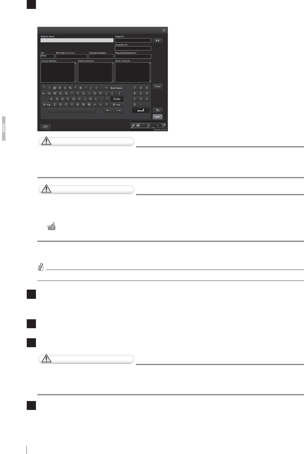
3-10
Basic Operation
3
FDR D-EVO
II Operation Manual 897N120339A
5 7KH3DWLHQW,QIRUPDWLRQ,QSXW6FUHHQEHORZDSSHDUVIROORZLQJWKHRSHQLQJVFUHHQRQWKHLPDJH
SURFHVVLQJXQLWPRQLWRU
Patient Information Input Screen
CAUTIONS
An error occurs if the system is started up immediately after shutdown.
7RUHVWDUWWKHV\VWHPLQFOXGLQJWKHFRQWUROFDELQHWPDNHVXUHWKDWWKHSRZHUVWDWXV/('RIWKH
FRQWUROFDELQHWLVRIIDQGWKHQSUHVVWKHSRZHUVZLWFKIRUWKHLPDJHSURFHVVLQJXQLW
CAUTIONS
Ɣ
'RQRWFRQQHFWGLVFRQQHFWWKHÀDWSDQHOVHQVRUWRIURPWKHSRZHUVXSSO\XQLWRUWRIURPWKH
GRFNLQJVWDQGZKLOHWKHPHVVDJH³&DOLEUDWLQJ´LVGLVSOD\HGLQWKHFRQQHFWHGGHYLFHVVWDWXV
DIWHUWKHV\VWHPVWDUWXS2WKHUZLVHWKHV\VWHPGRHVQRWVWDUWXSQRUPDOO\UHVXOWLQJLQDQHUURU
Ɣ may be displayed in the connected devices status while information on radio wave
VWUHQJWKLVEHLQJDFTXLUHGIURPWKHÀDWSDQHOVHQVRU
(When the DR-ID 1200DU is used)
Make sure that the power cable is connected to the image processing unit.
1 7XUQRQWKHPDLQVZLWFKRQWKHGRFNLQJVWDQG
Make sure that the POWER lamp among the status lamps is lit in blue.
2 ,QVWDOOWKHIXOO\FKDUJHGEDWWHU\SDFNWRWKHÀDWSDQHOVHQVRU
3 :KHQWKHRSWLRQDODFFHVVSRLQWLVXVHGFRQQHFWWKHDFFHVVSRLQWWRWKHLPDJHSURFHVVLQJXQLW
CAUTIONS
8VHWKHRSWLRQDODFFHVVSRLQWE\FRQQHFWLQJLWWRWKHSUHVHWLPDJHSURFHVVLQJXQLWDQGWRWKH86%
FRQQHFWRU'RQRWXVHWKHRSWLRQDODFFHVVSRLQWE\FRQQHFWLQJLWWRRWKHULPDJHSURFHVVLQJXQLWDQG
or USB connector.
4 7XUQRQWKHLPDJHSURFHVVLQJXQLW
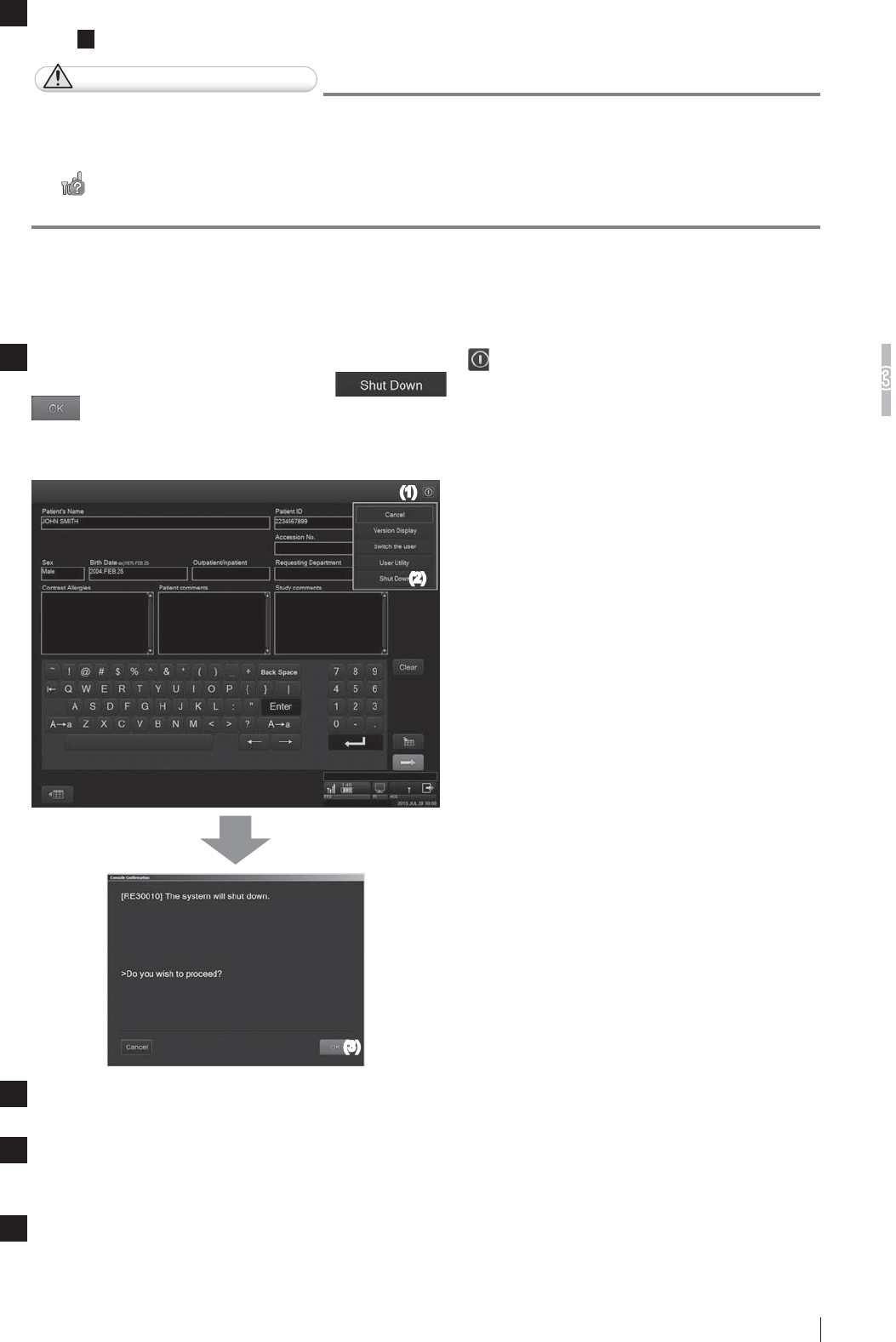
3-11
Basic Operation
3
FDR D-EVO
II Operation Manual 897N120339A
5 7KH3DWLHQW,QIRUPDWLRQ,QSXW6FUHHQDSSHDUVRQWKHLPDJHSURFHVVLQJXQLWPRQLWRUDVVKRZQLQ
Step
5 RQ3DJH
CAUTIONS
Ɣ
'RQRWFRQQHFWGLVFRQQHFWWKHÀDWSDQHOVHQVRUWRIURPWKHSRZHUVXSSO\XQLWRUWRIURPWKH
GRFNLQJVWDQGZKLOHWKHPHVVDJH³&DOLEUDWLQJ´LVGLVSOD\HGLQWKHFRQQHFWHGGHYLFHVVWDWXV
DIWHUWKHV\VWHPVWDUWXS2WKHUZLVHWKHV\VWHPGRHVQRWVWDUWXSQRUPDOO\UHVXOWLQJLQDQHUURU
Ɣ may be displayed in the connected devices status while information on radio wave
VWUHQJWKLVEHLQJDFTXLUHGIURPWKHÀDWSDQHOVHQVRU
6KXWWLQJ'RZQWKH6\VWHP
(When the DR-ID 1200PU is used)
1 &RQ¿UPWKDWWKHHTXLSPHQWLVQRWUXQQLQJ7RXFKWKH EXWWRQDWWKHXSSHUULJKWRIWKHLPDJH
SURFHVVLQJXQLWGLVSOD\DQGWKHQWKH button from the displayed menu. Touch the
EXWWRQLQWKHGLVSOD\HGFRQ¿UPDWLRQZLQGRZ
7KHLPDJHSURFHVVLQJXQLWZLOOVKXWGRZQLQDIHZPLQXWHV,IWKHFRQWUROFDELQHWLVLQFOXGHGLQWKH
system, the control cabinet will also turn off automatically.
(1)
(2)
(3)
2 Turn off the display as necessary.
3 0DNHVXUHWKDWFDOLEUDWLRQRIWKHÀDWSDQHOVHQVRULVFRPSOHWHG
:KHQFRPSOHWHGWKH5($'<ODPSRIWKHÀDWSDQHOVHQVRUWXUQVRII
4
:KHQWKHRSWLRQDODFFHVVSRLQWLVXVHGUHPRYHWKHDFFHVVSRLQWIURPWKHLPDJHSURFHVVLQJXQLW
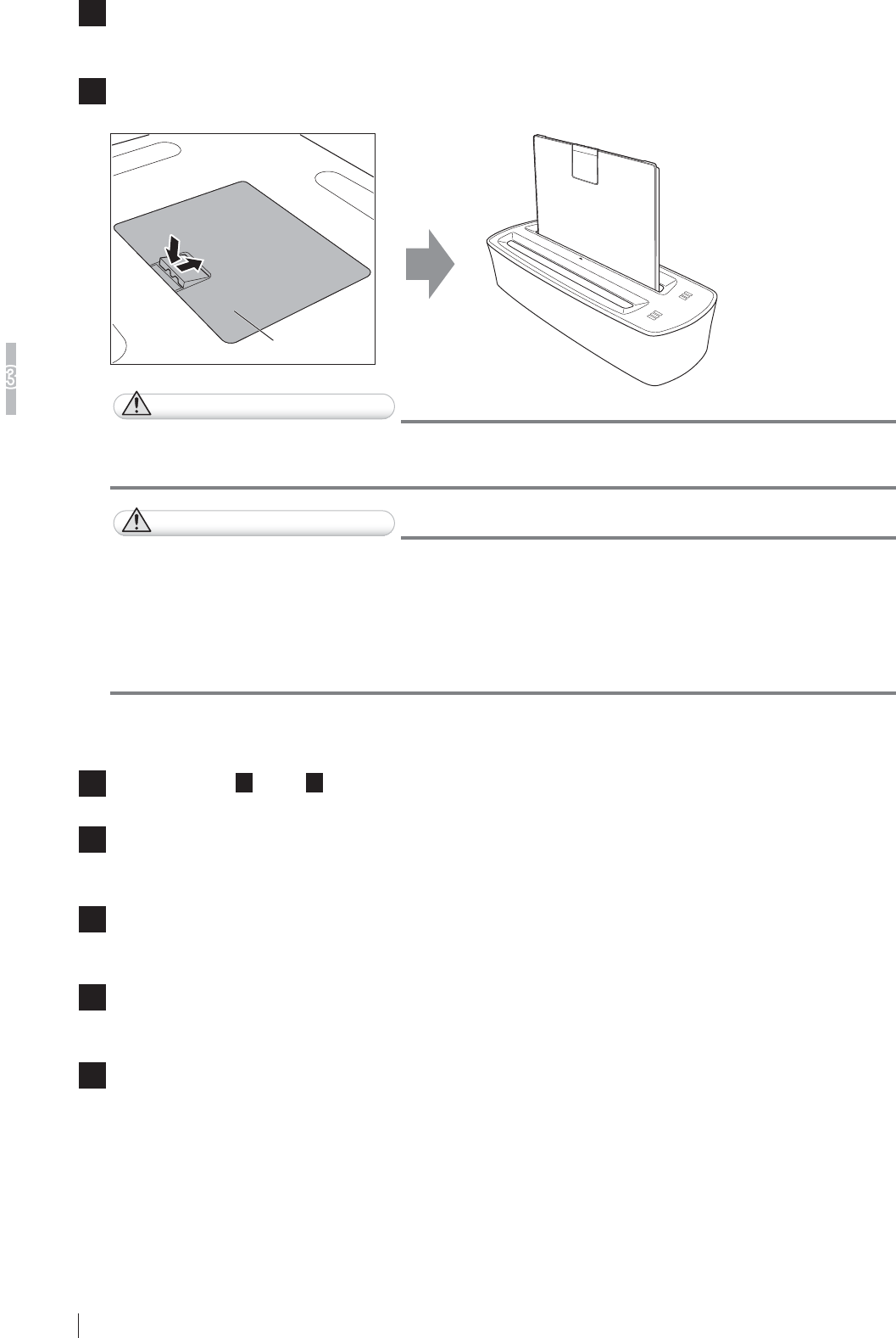
3-12
Basic Operation
3
FDR D-EVO
II Operation Manual 897N120339A
5 Press the OFF side of the main switch of the power supply unit.
Make sure that the power status LED is off.
6 5HPRYHWKHEDWWHU\SDFNIURPWKHÀDWSDQHOVHQVRU6HWWKHVHEDWWHU\SDFNVLQWKHEDWWHU\
FKDUJHU
Battery pack
CAUTIONS
If the control cabinet is included in the system, do not turn off the control cabinet with the main
switch. Shutdown operation may not be performed normally.
CAUTIONS
:KHQWKHV\VWHPLVVKXWGRZQLPDJHTXDOLW\DGMXVWPHQWLVSHUIRUPHGIRUREWDLQLQJRSWLPDO
GLDJQRVWLFLPDJHV
'RQRWGLVFRQQHFWWKH6(FDEOHRU6(FRPPXQLFDWLRQFDEOHXQWLOV\VWHPVKXWGRZQZKHQWKHÀDW
panel sensor is used in wired communication mode.
5HPRYHWKHEDWWHU\SDFNDIWHUFRQ¿UPLQJV\VWHPVKXWGRZQZKHQWKHÀDWSDQHOVHQVRULVXVHG
in wireless communication mode.
(When the DR-ID 1200DU is used)
1 Perform Steps 1 1 and 2RQ3DJH
2 :KHQWKHRSWLRQDODFFHVVSRLQWLVXVHGUHPRYHWKHDFFHVVSRLQWIURPWKHLPDJHSURFHVVLQJ
unit.
3 0DNHVXUHWKDWFDOLEUDWLRQRIWKHÀDWSDQHOVHQVRULVFRPSOHWHG
:KHQFRPSOHWHGWKH5($'<ODPSRIWKHÀDWSDQHOVHQVRUWXUQVRII
4 7XUQRIIWKHPDLQVZLWFKRQWKHGRFNLQJVWDQG
Make sure that the POWER lamp among the status lamps is off.
5 5HPRYHWKHEDWWHU\SDFNIURPWKHÀDWSDQHOVHQVRU6HWWKHVHEDWWHU\SDFNVLQWKHEDWWHU\
FKDUJHU

3-13
Basic Operation
3
FDR D-EVO
II Operation Manual 897N120339A
3.3 Routine Operations
FDR D-EVO II routine operations can be broadly divided into the following three steps.
Step 1 Entering the Patient Information
Step 2 Selecting the Anatomical Region and Exposure/Study Menu
Step 3 X-ray Exposure
(See page 3-14.)
(See page 3-15.)
(See page 3-17.)
HINT
Operations that are actually performed on the FDR D-EVO II are only those described in “ Step 3 X-ray Exposure”.
Other operations are performed on the image processing unit.
For details, see “DR-ID 300CL Operation Manual”.
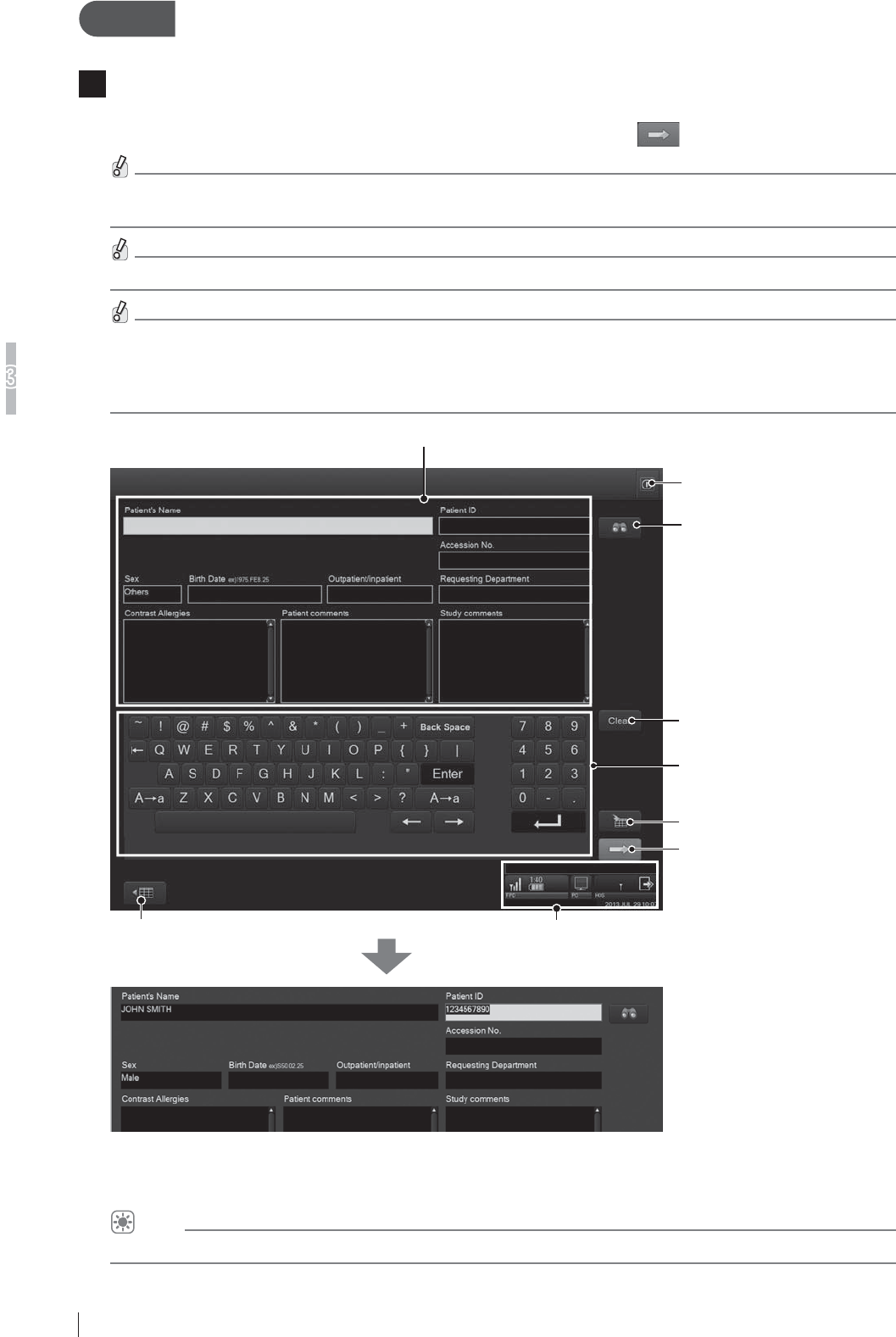
3-14
Basic Operation
3
FDR D-EVO
II Operation Manual 897N120339A
Step 1 (QWHULQJWKH3DWLHQW,QIRUPDWLRQ
1 7KH3DWLHQW,QIRUPDWLRQ,QSXW6FUHHQEHORZLVGLVSOD\HGRQWKHLPDJHSURFHVVLQJXQLWGLVSOD\
immediately after startup.
Enter patient information items appropriately, and then touch the button.
Not all the items of patient information need to be input.
Input any one of the items in order to proceed to the next operation.
When the optional card reader is provided, patient information can be input by reading from a magnetic card.
Observe the following when the message “Calibrating...” is displayed in the connected devices status.
'RQRWVXEMHFWWKHÀDWSDQHOVHQVRUWRVKRFN
• Do not deliver radiation.
'RQRWFRQQHFWGLVFRQQHFWWKHÀDWSDQHOVHQVRUWRIURPWKHSRZHUVXSSO\XQLWRUWRIURPWKHGRFNLQJVWDQG
Patient information input field
Input patient information.
Clears patient information
(except for technologist).
Operates the Patient Information
Database function to input patient
information.
Tool button
Displays the “Study List screen”.
Screen keyboard
Used to input characters in the
patient information input field.
Reserves a study.
Terminates patient information
input, and proceeds to exposure
menu selection.
Connected devices status
Connected devices status display field.
Displays the status of connected devices.
Patient information includes the following items.
Patient’s Name / Sex / Birth Date / Outpatient/Inpatient / Patient ID / Accession No. / Requesting Department / Contrast Allergies /
Patient comments / Study comments
HINT
You can change patient information input items and their display order in the User Utility settings.
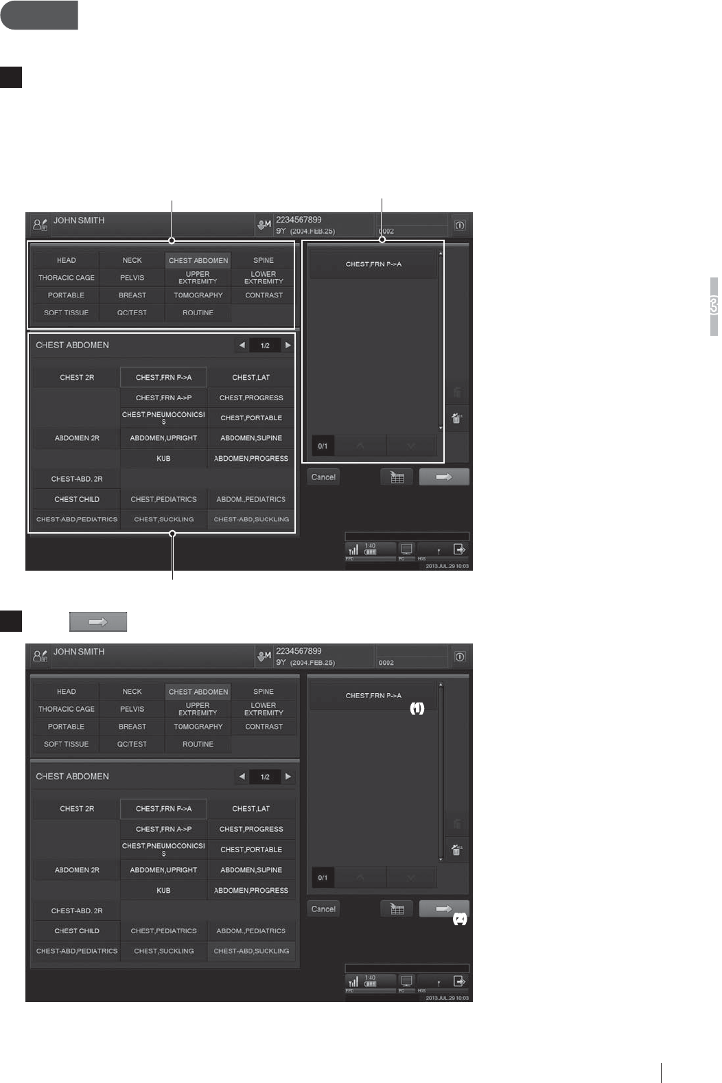
3-15
Basic Operation
3
FDR D-EVO
II Operation Manual 897N120339A
Step 2 6HOHFWLQJWKH$QDWRPLFDO5HJLRQDQG([SRVXUH6WXG\
Menu
1 The Exposure Menu Selection Screen is displayed.
6HOHFWDQDQDWRPLFDOUHJLRQIURPWKHGLVSOD\JURXSOLVWDQGWKHQVHOHFWDQH[SRVXUHPHQXIURP
WKHH[SRVXUHPHQXOLVWUHJLVWHUHGWRWKHGLVSOD\JURXSRQWKHORZHUVLGH0RUHWKDQRQHPHQX
can be selected.)
7KHVHOHFWHGH[SRVXUHPHQXVLVGLVSOD\HGLQWKHVHOHFWHGH[SRVXUHPHQXOLVWRQWKHULJKWVLGH
of the screen.
Selected exposure menu listDisplay group list
Exposure menu list registered to the display group
2 Touch DIWHUVHOHFWLQJH[SRVXUHPHQXV
(1)
(2)
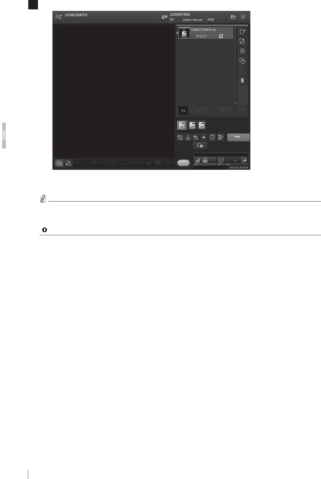
3-16
Basic Operation
3
FDR D-EVO
II Operation Manual 897N120339A
3 The Study Screen is then displayed.
:KHQUHJLVWHULQJDQH[SRVXUHPHQXVPRYHWKHÀDWSDQHOVHQVRUDQGLPDJHSURFHVVLQJXQLWRUDFFHVVSRLQWFORVH
to each other, so that they are within the range of wireless communication.
If the units are out of the range of wireless communication, the message may appear when an exposure menu(s)
LVUHJLVWHUHG,QWKLVFDVHPRYHWKHÀDWSDQHOVHQVRUDQGLPDJHSURFHVVLQJXQLWRUDFFHVVSRLQWFORVHWRHDFK
other, so that they are within the range of wireless communication, and then follow the displayed message.
For details, see “4.1 When a Message Appears on the Image Processing Unit”.
3-17
Basic Operation
3
FDR D-EVO
II Operation Manual 897N120339A
Step 3 ;UD\([SRVXUH
When settings on the image processing unit have been completed, you can perform an exposure.
CAUTIONS
Ɣ 0DNHVXUHWRLGHQWLI\DSDWLHQWDJDLQVWWKHQDPHRUELUWKGDWHDQGWKHQKDYHKLPKHUWDNHD
SURSHUSRVLWLRQLQJIRUH[SRVXUH
Ɣ 0DNHVXUHWRFRQ¿UPWKHH[SRVXUHPHQXWREHXVHGDQGWKHQKDYHDSDWLHQWWDNHDSURSHU
SRVLWLRQLQJIRUH[SRVXUH
Ɣ :KHQPXOWLSOHSDQHOVDUHXVHGPDNHVXUHWKDWWKH5($'<ODPSDPRQJWKHVWDWXVODPSV
RIWKHÀDWSDQHOVHQVRULVOLWLQRUGHUWRFRQ¿UPWKDWLWLVWKHFRUUHFWRQHIRUWKHVHOHFWHG
WHFKQLTXH
Ɣ $IWHUVWDUWLQJH[SRVLQJRSHUDWLRQGRQRWGLVFRQQHFWRUFRQQHFWWKHFRQQHFWRU,IWKH
FRQQHFWRULVGLVFRQQHFWHGRUFRQQHFWHGUDGLRJUDSK\PD\EHFRPHLPSRVVLEOHRUQRUPDO
LPDJHVFDQQRWEHREWDLQHG
HINT
0RELOHH[SRVXUHVFDQEHPDGHE\FDUU\LQJWKHÀDWSDQHOVHQVRUQRWHERRNFRPSXWHULPDJHSURFHVVLQJXQLWDQG
the optional access point.
>@3RVLWLRQLQJWKHSDWLHQW
Position the patient.
CAUTIONS
([HUFLVHGXHFDUHVRWKDWDQLQWUDYHQRXVOLQHRUGUDLQWXEHSXWWRDSDWLHQWGRHVQRWKRRNLQWR
WKHHTXLSPHQW
For the exposure position of the upright-type/bed-type radiographic examination stand, see its Operation Manual.
:KHQPDNLQJDQH[SRVXUHGLUHFWO\XVLQJWKHÀDWSDQHOVHQVRU
set the exposure position by reference to the effective area.
For details on the effective area, see page A-6.
When the automatic X-ray detection function is used, see “Z.5 Precautions for the Automatic X-ray
Detection Function”.
Effective area
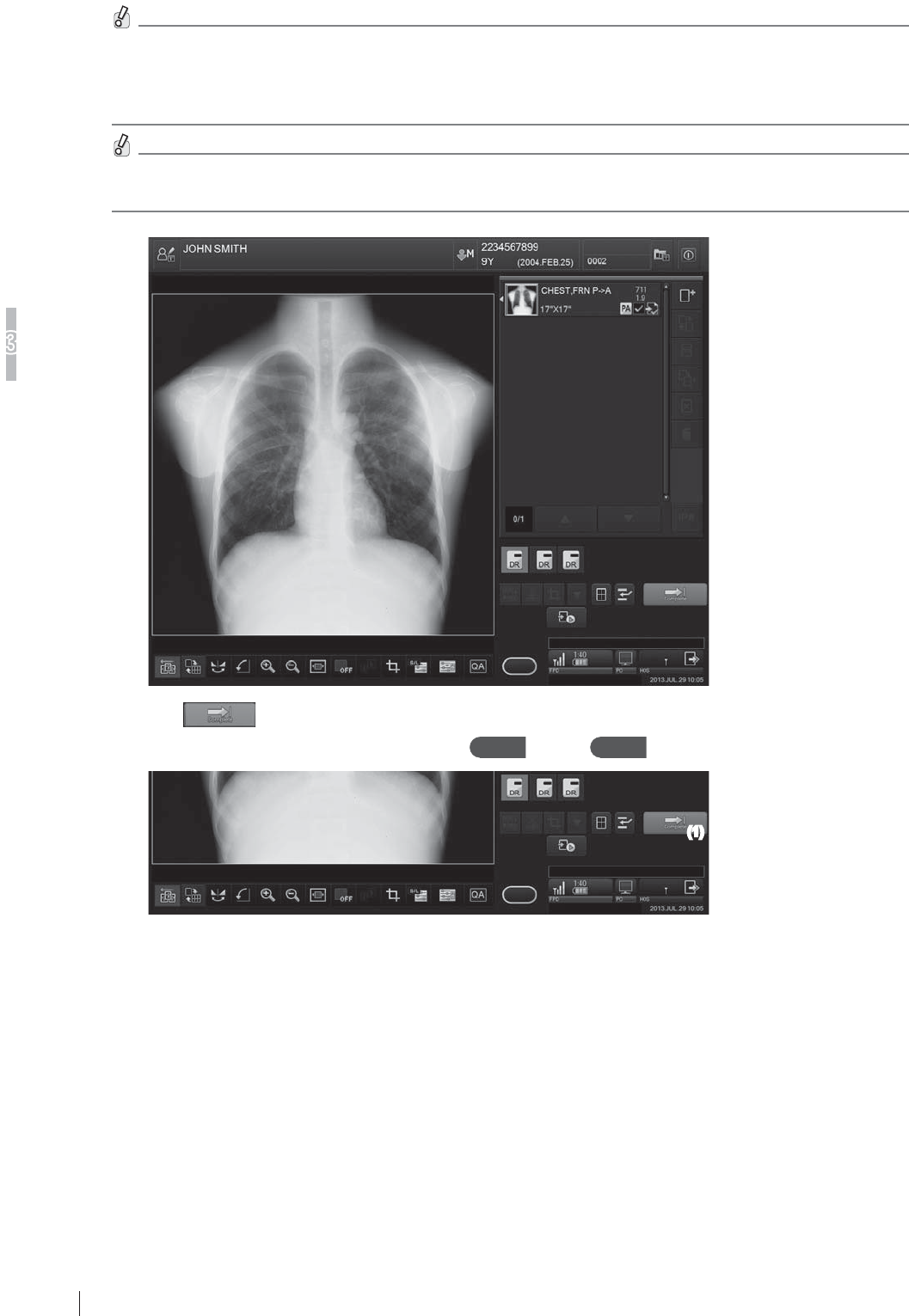
3-18
Basic Operation
3
FDR D-EVO
II Operation Manual 897N120339A
>@;UD\H[SRVXUH,PDJHGLVSOD\LQJ
0DNHDQH[SRVXUHDIWHUFRQ¿UPLQJWKDW6KRW5HDG\H[SRVXUHUHDG\VWDWXVLQGLFDWRULVOLWJUHHQLQWKHFRQQHFWHG
GHYLFHVVWDWXVRIWKHLPDJHSURFHVVLQJXQLW:KHQWKHDXWRPDWLF;UD\GHWHFWLRQIXQFWLRQLVXVHGLIWKHÀDWSDQHO
sensor is subjected to X-ray radiation without ShotReady lit in green, no image will be acquired although X-ray
radiation is applied.
$IWHUWKH H[SRVXUHGR QRW PRYHWKH LPDJHSURFHVVLQJ XQLW DQGWKH ÀDWSDQHO VHQVRU XQWLOD SURFHVVHGLPDJH
appears in the window of the image processing unit.
Touch the button at the lower right to complete the study.
To prepare for exposures of the next patient, repeat Step 1 through Step 3 .
(1)
The registration of the next new patient should be processed after more than 2 seconds.

3-19
Basic Operation
3
FDR D-EVO
II Operation Manual 897N120339A
[3] Sleep mode
When sleep mode is enabled, if no operation is performed for about two minutes without an exposure menu
UHJLVWHUHGWKHÀDWSDQHOVHQVRUZLOOHQWHUVOHHSPRGHDQGWKHSRZHUVWDWHLVFKDQJHGWRWKHSRZHUVDYLQJVWDWH
Once an exposure menu is registered, sleep mode is canceled automatically. In addition, when the SE cable is
FRQQHFWHGWRWKHÀDWSDQHOVHQVRURUZKHQWKHÀDWSDQHOVHQVRULVLQVHUWHGLQWRWKHGRFNLQJVWDQGVOHHSPRGHLV
canceled automatically.
([WUDVOHHSPRGHZKLFKFDQIXUWKHUVDYHSRZHUFDQDOVREHVHW,IDVSHFL¿HGWLPHKDVHODSVHGDIWHUDOOÀDWSDQHO
sensors enter sleep mode, they enter extra sleep mode. When the sleep release/memory exposure mode start
button is pressed, extra sleep mode is canceled.
In sleep mode or extra sleep mode, the operating time of the battery pack becomes longer since the power is saved.
,IWKHÀDWSDQHOVHQVRULVEHLQJFDOLEUDWHGRULILWGHWHFWVDQLPSDFWLWPD\WDNHORQJHUWLPHWRHQWHUVOHHSPRGH
or sleep mode may be canceled temporarily. When the setting of sleep mode or extra sleep mode needs to be
FKDQJHGFRQVXOWRXURI¿FLDOGHDOHURUORFDOUHSUHVHQWDWLYH
>@([WHQGHG,PDJH5HDGRXW
When the Extended Image Readout mode is enabled, a long exposure for up to ten seconds is available. To set the
([WHQGHG,PDJH5HDGRXWPRGHFRQVXOWRXURI¿FLDOGHDOHURUORFDOUHSUHVHQWDWLYH)RUGHWDLOVRQKRZWRXVHWKH
Extended Image Readout mode, see the “Console Advance (DR-ID 300CL) Reference Guide”.
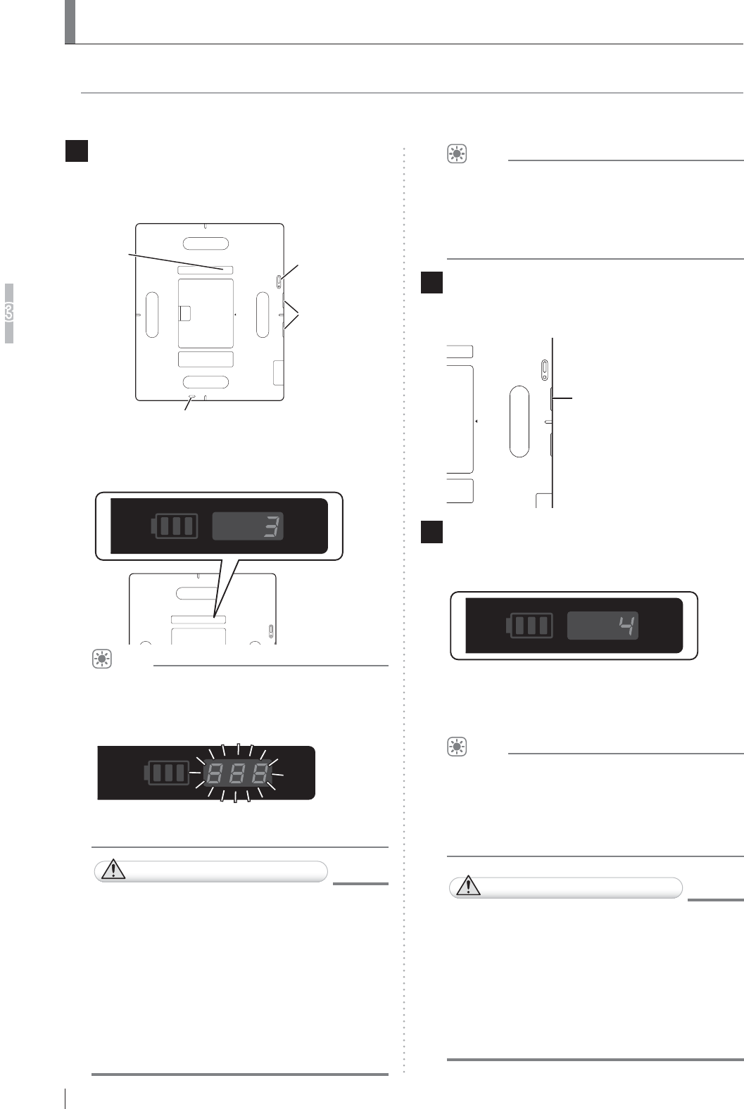
3-20
Basic Operation
3
FDR D-EVO
II Operation Manual 897N120339A
3.4 How to Use Memory Exposure Mode
,QWKHPHPRU\H[SRVXUHPRGHDPD[LPXPRIH[SRVXUHVFDQEHPDGHRQO\ZLWKWKHÀDWSDQHO
sensor, without using the image processing unit.
3.4.1 How to Start up and Use Memory Exposure Mode
1 Press and hold the memory exposure mode
VWDUWEXWWRQDQGWKHVOHHSUHOHDVHPHPRU\
exposure mode start button at the same
time for 2 seconds.
Memory exposure mode start button
Sleep release/
memory exposure
mode start button
Status lamp
Memory
exposure
mode status
:KHQWKHQXPEHURILPDJHVVWRUHGRQWKHÀDWSDQHO
sensor is displayed in the memory exposure mode
status, the start-up process is completed.
HINT
Before the start-up process is completed, calibration
RIWKHÀDWSDQHOVHQVRUPD\EHSHUIRUPHG
During calibration, “888” blinks in the memory
exposure mode status.
When calibration is completed, the number of
LPDJHVVWRUHGRQWKHÀDWSDQHOVHQVRULVGLVSOD\HG
CAUTIONS
When the memory exposure mode is started
XSZKLOHWKHÀDWSDQHOVHQVRULVLQXVH
DPHVVDJHLVGLVSOD\HGRQWKHVFUHHQRI
WKHLPDJHSURFHVVLQJXQLWLQGLFDWLQJWKDW
communication is disconnected. Since this is
QRWDQHUURUVHOHFW³2.´WRFRQWLQXHRSHUDWLRQ
+RZHYHULIWKHIROORZLQJHUURUFRGHVDUH
GLVSOD\HGWDNHDSSURSULDWHPHDVXUHV
DFFRUGLQJWRWKHLQVWUXFWLRQVGLVSOD\HGRQWKH
VFUHHQ;;;HUURUFRGHVEHJLQQLQJZLWK
³´RU
HINT
When the memory exposure mode is started up, the
ÀDWSDQHOVHQVRUHQWHUV;UD\GHWHFWLRQPRGH
For details on X-ray detection mode, see “Z.5
Precautions for the Automatic X-ray Detection
Function”.
2 :KHQWKH5($'<ODPSDPRQJWKHVWDWXV
ODPSVLVDXWRPDWLFDOO\OLWLQJUHHQPDNHDQ
exposure.
READY
3 0DNHVXUHWKDWWKHQXPEHURILPDJHV
displayed in the memory exposure mode
status has increased.
When the READY lamp among the status lamps is
automatically lit in green, the next exposure can be
made.
HINT
The value displayed as the number of images is
used for managing the images.
For example, when “3” is displayed before an
exposure and then “4” is displayed after the
exposure, the number of the exposed image is “4”.
CAUTIONS
Ɣ 1RWHWKDWZKHQWKHÀDWSDQHOVHQVRULV
used in the memory exposure mode, if a
VWURQJLPSDFWLVDSSOLHGWRWKHÀDWSDQHO
VHQVRUDZKLWHLPDJHPD\EHREWDLQHG
LQFUHPHQWLQJWKHQXPEHURILPDJHV
Ɣ 0DQDJHWKHUHFRUGVRIH[SRVHGLPDJHVWR
identify the correspondence between the
LPDJHQXPEHUDQGWKHSDWLHQWQDPH
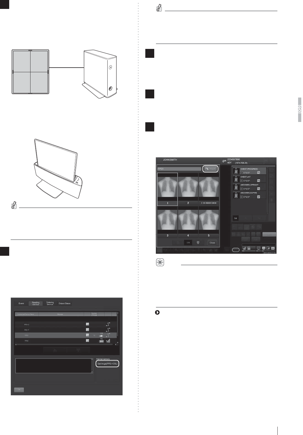
3-21
Basic Operation
3
FDR D-EVO
II Operation Manual 897N120339A
+RZWR/RDG,PDJHV
1 &RQQHFWLQVHUWWKHÀDWSDQHOVHQVRUWRLQWR
each device.
(When the DR-ID 1200PU is used)
&RQQHFWWKHÀDWSDQHOVHQVRUWRWKHSRZHUVXSSO\
unit using the SE cable.
Flat panel sensor Power supply unit
(When the DR-ID 1200DU is used)
,QVHUWWKHÀDWSDQHOVHQVRULQWRWKHGRFNLQJVWDQG
)RUGHWDLOVRQKRZWRLQVHUWWKHÀDWSDQHOVHQVRU
into the docking stand, see “3.1.10 Attaching the
Flat Panel Sensor to the Docking Stand” on Page
3-8.
2 7RORDGLPDJHVVWRUHGRQWKHÀDWSDQHO
VHQVRULQWRWKHLPDJHSURFHVVLQJXQLW
GLVSOD\WKH³,PDJH5HDGHU6WDWXVZLQGRZ´
RQWKHLPDJHSURFHVVLQJXQLWVHOHFWWKHÀDW
SDQHOVHQVRUDQGWKHQ³*HW,PDJH)3'Æ
&6/´
,PDJHVVWRUHGLQWKHÀDWSDQHOVHQVRUDUHORDGHG
onto the image processing unit.
:KHQFDOLEUDWLRQRIWKHÀDWSDQHOVHQVRULVLQ
progress, an error may occur.
If this happens, wait for a while and then try image
loading again.
3 'LVSOD\WKH³6WXG\VFUHHQ´RIWKHSDWLHQW
FRUUHVSRQGLQJWRWKHORDGHGLPDJHVDQG
VHOHFWWKHH[SRVXUHPHQXWREHOLQNHGZLWK
WKHLPDJHV
4 6HOHFWWKHVHOHFWRURIWKHÀDWSDQHOVHQVRU
LQZKLFKWKHLPDJHLVVWRUHGDQGWKHQVHOHFW
>,PDJH%R[@
5 2QWKH³,PDJH/LEUDU\VFUHHQ´VHOHFWWKH
LPDJHRIZKLFKWKHQXPEHULVWREHOLQNHG
with the exposure menu and then select
[Import].
HINT
When an image that has not been linked with an
exposure menu is left, if images are acquired from
WKHÀDWSDQHOVHQVRUWKHDFTXLVLWLRQGDWHDQGWLPH
is added to the image No. of the image that was
acquired previously.
For details, see the “Console Advance (DR-ID
300CL) Reference Guide”.

3-22
Basic Operation
3
FDR D-EVO
II Operation Manual 897N120339A
3.4.3 List of Error Codes
If an error occurs while starting up or using the memory exposure mode, the corresponding error
code is displayed in the memory exposure mode status. Terminate the memory exposure mode and
then perform the countermeasure against each error. Error codes are listed in the table below.
Error code Occurrence condition Countermeasure
E01 &DOLEUDWLRQRIWKHÀDWSDQHOVHQVRULV
in progress.
Wait for a while and then start up the memory
exposure mode again.
An exposure menu is registered on
the image processing unit.
Terminate or suspend the study on the image
processing unit.
The SE cable or SE communication
FDEOHLVFRQQHFWHGWRWKHÀDWSDQHO
sensor.
Disconnect the SE cable or SE communication
FDEOHIURPWKHÀDWSDQHOVHQVRU
7KHÀDWSDQHOVHQVRULVLQVHUWHGLQWR
the docking stand.
5HPRYHWKHÀDWSDQHOVHQVRUIURPWKHGRFNLQJ
stand.
E03 An X-ray is irradiated when exposure
is not available.
&RQQHFWWKHÀDWSDQHOVHQVRUWRWKHLPDJH
processing unit or remove and attach the
battery pack and then restart the memory
exposure mode.
E04 7KHÀDWSDQHOVHQVRUGHWHFWVDQ
impact.
&RQQHFWWKHÀDWSDQHOVHQVRUWRWKHLPDJH
processing unit.
E05 The remaining capacity of the battery
pack is low.
Replace the battery pack.
E06, E07, E17, E18 7KHWHPSHUDWXUHRIWKHÀDWSDQHO
sensor or battery back is abnormal.
Check if the operating temperature is within
WKHWHPSHUDWXUHUDQJHVSHFL¿HGLQWKH
environmental operating conditions.
E08, E09, E11 to
E14, E16, E19
$QDEQRUPDOLW\RFFXUUHGRQWKHÀDW
panel sensor.
&RQVXOWRXURI¿FLDOGHDOHURUORFDO
representative.
E10 Calibration has failed. Restart the memory exposure mode.
E15 Image storage has failed. &RQVXOWRXURI¿FLDOGHDOHURUORFDO
representative.
,IWKHVDPHHUURURFFXUVUHSHDWHGO\FRQVXOWRXURI¿FLDOGHDOHURUORFDOUHSUHVHQWDWLYH
3.4.4 How to Terminate Memory Exposure Mode
(DR-ID 1200PU)
5HPRYHWKHEDWWHU\SDFNIURPWKHÀDWSDQHOVHQVRU
2UFRQQHFWWKHÀDWSDQHOVHQVRUWRWKHSRZHUVXSSO\XQLWRUWRWKHRSWLRQDODFFHVVSRLQWE\XVLQJ
the SE cable or SE communication cable.
(DR-ID 1200DU)
5HPRYHWKHEDWWHU\SDFNIURPWKHÀDWSDQHOVHQVRU
2ULQVHUWWKHÀDWSDQHOVHQVRULQWRWKHGRFNLQJVWDQG
HINT
,PDJHVH[SRVHGLQWKHPHPRU\H[SRVXUHPRGHDUHQRWORVWHYHQLIWKHEDWWHU\SDFNLVUHPRYHGIURPWKHÀDWSDQHO
sensor.

4-1
Troubleshooting
4
FDR D-EVO
II Operation Manual 897N120339A
Chapter 47URXEOHVKRRWLQJ
4.1
:KHQD0HVVDJH$SSHDUVRQWKH,PDJH
3URFHVVLQJ8QLW
This section describes the warning dialog box and error messages.
,IDQHUURUZKLFKFDQQRWEHKDQGOHGRUWKHVDPHHUURUUHFXUVIUHTXHQWO\FRQWDFWRXURI¿FLDOGHDOHURU
FUJIFILM Representative.
,IDQHUURURIXQNQRZQFDXVHRFFXUVGRQRWFRQWLQXHWKHRSHUDWLRQDQGFRQWDFWRXURI¿FLDOGHDOHURU
FUJIFILM Representative.
>@,IDZDUQLQJGLDORJER[DSSHDUV
If a communication error or an unexpected error has occurred, a warning dialog box pops up on
the screen. In such a case, after checking error details and closing the box, take appropriate action
immediately. Be sure not to continue the operation of the image processing unit without taking an
appropriate action.
If any operation is performed while a warning dialog box is displayed, another screen may be
displayed, hiding the dialog box behind. In this case, press the [Enter] key to close the hidden box.
When a warning dialog box that contains an error code beginning with “10” appears, follow the
steps below.
1 5HDGDPHVVDJHLQWKHZDUQLQJGLDORJER[DQGWKHQFOLFN>2.@LQWKHGLDORJER[
2 'HWDFKWKHEDWWHU\SDFNVIRUDOOÀDWSDQHOVHQVRUV
3 &RQ¿UPWKDWWKHÀDWSDQHOVHQVRUVDUHWXUQHGRII
4 5HDWWDFKWKHEDWWHU\SDFNVWRWKHÀDWSDQHOVHQVRUV7KHQWKHV\VWHPUHVWDUWV
>@,IWKHPHVVDJHGLDORJXHER[0'DSSHDUV
The following message dialogue box appears not only when the image processing unit starts up but
DOVRZKHQDFRPPXQLFDWLRQHUURURFFXUVLQWKHÀDWSDQHOVHQVRURULPDJHSURFHVVLQJXQLW
&KHFNLIWKHÀDWSDQHOVHQVRULVZLWKLQWKHUHDFKRIUDGLRZDYHV,IWKHXQLWLVRXWRIWKHUDQJHPRYH
WKHLPDJHSURFHVVLQJXQLWDQGWKHÀDWSDQHOVHQVRUFORVHUWRHDFKRWKHU
,QDGGLWLRQFRQ¿UPWKDWWKHUHDUHQRREVWDFOHVZKLFKDUHLQWHUUXSWLQJWKHFRPPXQLFDWLRQ
When the problem is not solved within a short time after the message box is displayed, perform the
following procedure.

4-2
7URXEOHVKRRWLQJ
4
FDR D-EVO
II Operation Manual 897N120339A
:KHQ DFTXLULQJ GDWD LV LQWHUUXSWHG WKH LPDJH GDWD LV PDLQWDLQHG LQ WKH ÀDW SDQHO VHQVRU LI UHFRQQHFWLRQ LV
VXFFHVVIXOO\PDGHRUXQWLOSRZHUVXSSO\RIÀDWSDQHOVHQVRULVWXUQHGRIIVRLPDJHGDWDZLOOQRWEHORVW
,QWKHFDVHRIWKHPHPRU\H[SRVXUHPRGHLPDJHVVWRUHGLQWKHÀDWSDQHOVHQVRUDUHQRWORVWHYHQLIWKHÀDWSDQHO
sensor is turned off.
1 6HOHFW>2.@RQWKHPHVVDJHER[
2 &KHFNLIWKHHTXLSPHQWFRQQHFWHGZLWKWKHLPDJHSURFHVVLQJXQLWLVWXUQHGRQ
If any equipment is turned off, turn it on and wait for a while.
3 ,IWKHSUREOHPLVQRWVROYHGVKXWGRZQWKHLPDJHSURFHVVLQJXQLW
4 0DNHVXUHWKDWWKHSRZHUVWDWXV/('RIWKHFRQWUROFDELQHWLVRIIDQGWKHQUHVWDUWWKHLPDJH
SURFHVVLQJXQLW
This step is not required if the control cabinet is not included in the system.
If the power status LED of the control cabinet does not turn off even after approximately 10 minutes have passed
following the shutdown of the image processing unit, press and hold the main switch of the control cabinet.
:KHQWKHLPDJHSURFHVVLQJXQLWLVUHVWDUWHGDQGWKHVDPHHUURUPHVVDJHER[LVGLVSOD\HGFRQWDFWRXURI¿FLDO
dealer or FUJIFILM Representative.
>@,IDQH[SRVHGLPDJHFDQQRWEHDFTXLUHG
'RQRWUHPRYHWKHEDWWHU\SDFNIURPWKHÀDWSDQHOVHQVRUXQWLODQH[SRVHGLPDJHLVDFTXLUHG,IUHPRYHGWKH
image data and the exposure menu data used for the exposure will be lost.
If an exposed image cannot be acquired, the following error message may be displayed.
1 ,IZLUHOHVVFRPPXQLFDWLRQLVGLVFRQQHFWHGGXULQJLPDJHUHDGLQJWKHIROORZLQJPHVVDJHGLDORJ
is displayed.
<Error message of “MD10020”>
0RYH WKH ÀDW SDQHO VHQVRU FORVH WR WKH DFFHVV SRLQW FKHFN WKH GLVSOD\HG LFRQ (/ / ) to
make sure that proper wireless communication is established, and then select “Yes”. If the status is
QRWLPSURYHGFRQQHFWWKHÀDWSDQHOVHQVRUDQGWKHDFFHVVSRLQWXVLQJWKH6(FRPPXQLFDWLRQFDEOH
and then select “Yes”. If you select “No”, the image data and the exposure menu data used for the
exposure will be lost.
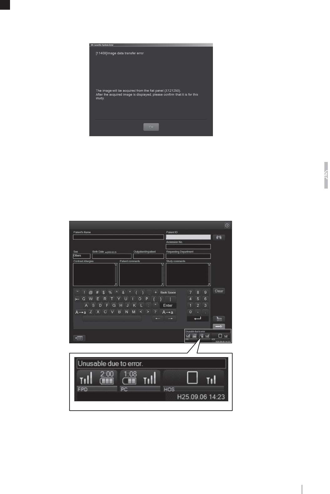
4-3
Troubleshooting
4
FDR D-EVO
II Operation Manual 897N120339A
2 If an exposure is made under a condition where wireless communication is unstable, the
IROORZLQJPHVVDJHGLDORJPD\EHGLVSOD\HG6HOHFW³2.´WRDFTXLUHWKHLPDJHDQGWKHQFKHFN
WKHDFTXLUHGLPDJH
<Error message of “11409”>
>@,IWKHGLDORJER[FRQWDLQLQJWKHHUURUPHVVDJHQXPEHUHG
13048 appears
7KHGLDORJXHER[DSSHDUVZKHQDVHYHUHVKRFNLVDSSOLHGWRWKHÀDWSDQHOVHQVRU0DNHVXUHWKDW
WKHH[WHULRURIWKHÀDWSDQHOVHQVRULVQRWGDPDJHGRUGHIRUPHGDQGWKDWQRDEQRUPDOLW\LVIRXQGLQ
the exposed image.
[5]
,I³8QXVDEOHGXHWRHUURU´DSSHDUVRQWKHLPDJHSURFHVVLQJXQLW
Connected devices status

4-4
Troubleshooting
4
FDR D-EVO
II Operation Manual 897N120339A
If “Unusable due to error.” is displayed on the image processing unit, remove the battery pack from
WKHÀDWSDQHOVHQVRUDQGLQVWDOOLWDJDLQ
Battery pack
Guide marksGuide marks
>@,IDQ\RWKHUPHVVDJHGLDORJXHER[DSSHDUV
If a message dialogue box other than those [1] – [5] appears on the image processing unit monitor,
read the message carefully and take appropriate action.

4-5
Troubleshooting
4
FDR D-EVO
II Operation Manual 897N120339A
4.2 How to Cope with an Error...
>@:KHQWKHLPDJHSURFHVVLQJXQLWKDQJVXS«
If an inappropriate processing is performed while this equipment is operating, the screen may freeze
and the system may hang up (processing disabled). In that case, shut down the equipment forcibly
according to the following procedure, and then restart it.
1 3UHVVWKH>&WUO@>$OW@>'HO@NH\VVLPXOWDQHRXVO\
2 ³:LQGRZV6HFXULW\´LVGLVSOD\HG
Select [Start Task Manager].
3 ³:LQGRZV7DVN0DQDJHU´LVGLVSOD\HG
Select “ProcessManagerMain.exe” in the list in the “Processes” tab, and then click [End Process].
4 7KHPHVVDJHER[LVGLVSOD\HG
Click [End Process] to terminate the image processing unit.
Depending on equipment status, an error message may not be displayed.
5 7KHGHVNWRSVFUHHQRIWKHRSHUDWLQJV\VWHPLVGLVSOD\HG
Close the “Windows Task Manager window”, and then select the [Start] button at the lower left of the screen. Select
[Restart] from the displayed menu.
CAUTIONS
Ɣ 0DNHVXUHWRVKXWGRZQWKHV\VWHPIROORZLQJWKHDERYHSURFHGXUHVLQFDVHRIDKDQJXSRI
WKHLPDJHSURFHVVLQJXQLW,IWKHSHUVRQDOFRPSXWHULVWXUQHGRIIZLWKRXWVKXWGRZQDQHUURU
may occur on the computer.
Ɣ 1RWHWKDWIRUFLEOHVKXWGRZQSURFHVVLQJRIWKHHTXLSPHQWLVDQHPHUJHQF\DFWLRQ'RQRWXVH
this action under normal situations.
6 If the control cabinet is included in the system, press and hold the main switch of the control
cabinet to turn it off.
7 7XUQRIIWKHPDLQVZLWFKRQWKHSRZHUVXSSO\XQLWDQGRQWKHGRFNLQJVWDQG
>@:KHQWKHLPDJHSURFHVVLQJXQLWLVWXUQHGRIIGXHWRDQ
HOHFWULFDORXWDJH
When the image processing unit is turned off due to an electrical outage, etc., take the following
actions according the condition when the power comes back on.
Ŷ ,IWKHSRZHUFRPHVEDFNRQVRRQDIWHUDQHOHFWULFDORXWDJH
Wait until the image processing unit restarts.
When the image processing unit has restarted, shut down the image processing unit by following
the normal procedure.
For details of system shutdown, see the “DR-ID 300CL Operation Manual”.
To restart the image processing unit, follow the procedure for the system startup.

4-6
Troubleshooting
4
FDR D-EVO
II Operation Manual 897N120339A
>@,IDKDUGGLVNRIWKHLPDJHSURFHVVLQJXQLWLVGDPDJHG
If one of the hard disks is damaged, a window indicating so will appear. In such a case, press the
)NH\DQGFRQWDFWRXURI¿FLDOGHDOHU
>@,IDZKLWHLPDJHLVGLVSOD\HGDIWHUDQH[SRVXUH
If a white image is displayed, a LAN communication error may have occurred.
&KHFNLIWKH/$1FRPPXQLFDWLRQFRQQHFWRUVDUHSURSHUO\FRQQHFWHGEHWZHHQWKHÀDWSDQHOVHQVRU
and the power supply unit or and between the power supply unit and the control cabinet. Make an
H[SRVXUHDJDLQDIWHUFRQ¿UPDWLRQ
[5] Precautions for operation when the device status is
³,QLWLDOL]LQJ´RU³&KDQJLQJ)3'´LQWKHLPDJHSURFHVVLQJ
XQLW¶V³2XWSXW'HYLFH6WDWXVZLQGRZ´
:KHQDÀDWSDQHOVHQVRULVDGGHGRUUHSODFHGRUZKHQWKHEDWWHU\RIDÀDWSDQHOVHQVRULVUHSODFHG
³,QLWLDOL]LQJ´RU³&KDQJLQJ)3'´LVGLVSOD\HGIRUDOOWKHÀDWSDQHOVHQVRUVLQWKHGHYLFHVWDWXV¿HOGRI
the image processing unit’s “Output Device Status window”. While either of the status messages is
displayed, you cannot make an exposure. Wait until the message disappears.
:KHQWKHÀDWSDQHOVHQVRULVWXUQHGRQE\FRQQHFWLQJWKHFDEOHIRUZLUHGFRPPXQLFDWLRQRUE\
attaching the battery pack immediately after the system starts up or an X-ray exposure is made, it
may take time before the next exposure becomes available.
(YHQLI³,QLWLDOL]LQJ´RU³&KDQJLQJ)3'´LVGLVSOD\HGIRUDOOWKHÀDWSDQHOVHQVRUVRQO\WKRVHZKLFKDUHDGGHGRU
replaced or those whose battery is replaced will be initialized.
>@,IWKHÀDWSDQHOVHQVRUFDQQRWEHXVHGLQZLUHOHVV
communication mode
,IWKHÀDWSDQHOVHQVRULVQRWUHFRJQL]HGLQDZLUHOHVVFRPPXQLFDWLRQPRGHXVHWKHFDEOHWR
connect the system in wired communication mode.
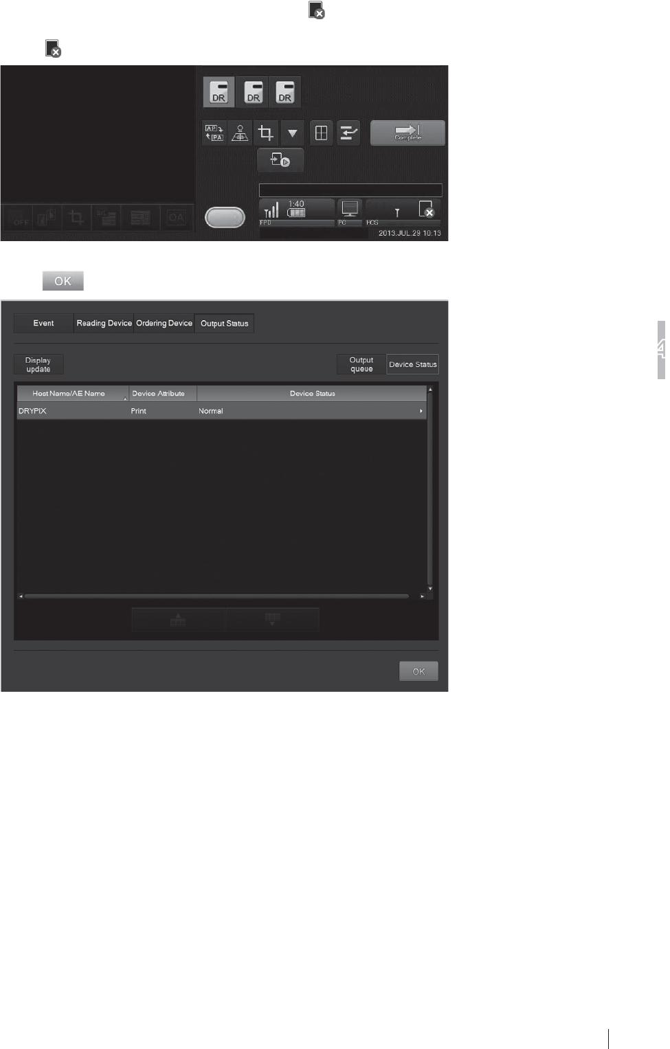
4-7
7URXEOHVKRRWLQJ
4
FDR D-EVO
II Operation Manual 897N120339A
[7] If an error occurs on an output destination device
If an error occurs on an output destination device, is displayed in the connected devices status.
In such a case, operate as follows.
Select .
The “Output Device Status window” is displayed.
Select after checking the connection status, and then take an appropriate action.
“Output Device Status window“

4-8
Troubleshooting
4
FDR D-EVO
II Operation Manual 897N120339A

5-1
Daily Inspection and Maintenance
5
FDR D-EVO
II Operation Manual 897N120339A
Chapter 5 Daily Inspection and
Maintenance
5.1
Daily User Inspection and Maintenance
During maintenance and inspection, strictly observe precautions contained in “Chapter 1 For Safe
Operation” in this manual for you to use the FDR D-EVO II under best conditions.
5.1.1 Daily Inspection (DR-ID 1200)
Inspection Before Use
• Make sure that the equipment starts up normally.
• Make sure that the equipment communicates with connected devices normally.
• Make sure that the time displayed is correct.
See “3.2 Starting Up and Shutting Down the System” (page 3-9).
,QVSHFWLRQ'XULQJ8VH
• Make sure that images are output normally.
See “3.3 Routine Operations” (page 3-13).
Inspection After Use
• Shut down the equipment.
See “3.2 Starting Up and Shutting Down the System” (page 3-9).
&OHDQLQJLQVWUXFWLRQV
Use a neutral detergent or ethanol to clean the outer surfaces.
CAUTIONS
Ɣ Do not use a solvent such as thinner or benzine, as it corrodes the outer surfaces.
Ɣ 0DNHVXUHQRWWROHWZDWHUGHWHUJHQWDQGHWKDQROJHWLQVLGHWKHHTXLSPHQW
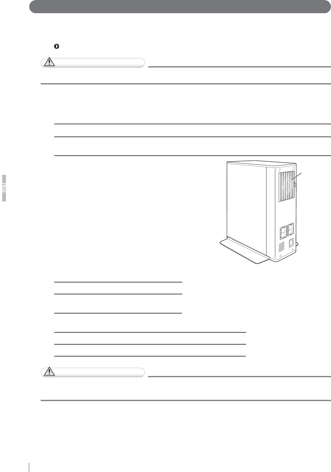
5-2
Daily Inspection and Maintenance
5
FDR D-EVO
II Operation Manual 897N120339A
5.1.2 Periodical Inspection
Inspection Every Three Months
Once every three months, remove any dirt or dust accumulated in each part of the equipment using
a vacuum cleaner or air duster, clean each part with a slightly moistened soft cloth and then wipe off
any moisture with a dry cloth.
See “2.2 Unit Names and the Functions” (page 2-4).
CAUTIONS
%HVXUHWRWXUQRIIWKHSRZHUEHIRUHFOHDQLQJHDFKSDUWRIWKHGHYLFH
Ŷ DR-ID 1200
DR-ID 1200
NO. Unit NO. Unit NO. Unit NO. Unit
1Flat panel sensor 2Power supply unit 3Power supply unit
$LU¿OWHU
4Image processing
unit
$LU¿OWHU
&OHDQWKHDLU¿OWHURQWKHUHDURIWKHSRZHU
supply unit with a vacuum cleaner.
Remove the louver while pressing the lever
RQWKHULJKWVLGHDQGWKHQFOHDQWKHDLU¿OWHU
with a vacuum cleaner after detaching it from
the louver.
Air filter
DR-ID 1200MC
NO. Unit NO. Unit
1Control cabinet 2Periphery of
devices
Optional
NO. Unit NO. Unit NO. Unit
1Battery charger 2Battery pack 3 Access Point
CAUTIONS
Ɣ (QVXUHVXI¿FLHQWVSDFHZKHQFOHDQLQJWKHHTXLSPHQWRQDWDEOHHWF
Ɣ ,IWKHLPDJHSURFHVVLQJXQLWLVVHFXUHGLQSODFHXQORFNLWEHIRUHFOHDQLQJ

A-1
Appendix A Specifications
FDR D-EVO
II Operation Manual 897N120339A
Appendix A Specifications
A.1 Specifications
6SHFL¿FDWLRQVRIWKH)'5D-EVO II are shown below.
$ 3URFHVVLQJ&DSDFLW\'5,'
Ŷ 5RXWLQHSURFHVVLQJZKHQWKHWZRLPDJHRXWSXWIRUPDWLVXVHGLQ
standard mode)
(1) Exposure interval
The exposure interval of the FDR D-EVO II is at least 9 seconds.
However, the interval varies depending on the region, the load to network communication, etc.
$ ,PDJH2XWSXW'5,'
Ŷ 6WDQGDUGSURFHVVLQJ
(1) Film output
Connection to the Imager makes it possible to obtain hard copies at the image reduction ratios
and in the formats below.
Ɣ)RUVWDQGDUGSL[HOGHQVLW\LPDJHV'5,'6(DQG'5,'6(
Output size Reduction ratio
7ZRLPDJHRXWSXW 2QHLPDJHRXWSXW
14” × 17” (35 × 43cm) 61% 100%
14” × 14” (35 × 35cm) 61% 100%
10” ×12” 85% 100%
8” × 10” 100% 100%
18 × 43cm 100% 100%
Ɣ)RUVWDQGDUGSL[HOGHQVLW\LPDJHV'5,'6(DQG'5,'6(
Output size Reduction ratio
7ZRLPDJHRXWSXW 2QHLPDJHRXWSXW
17” × 17” (43 × 43cm) 50% 82%
14” × 17” (35 × 43cm) 61% 100%
14” × 14” (35 × 35cm) 61% 100%
10” × 12” 85% 100%
8” × 10” 100% 100%
18 × 43cm 100% 100%
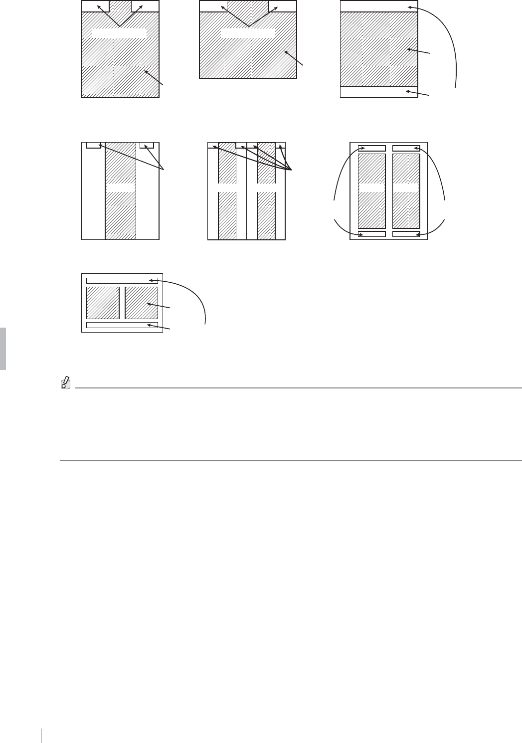
A-2
Appendix A Specifications
FDR D-EVO
II Operation Manual 897N120339A
[Fig. A.1]
(a) 14” × 17” (b) 17” × 14” (c) 14” × 14”
one-image output one-image output one-image output
(14” × 17” film) (14” × 17” film)
(14” × 17” film)
ID information
Image
Image
ID information
ID information
Image
(d) 18 × 43cm (e) 18 × 43cm (f) 18 × 43cm
one-image output two-image output two-image output
(14” × 17” film)
ID
information ID
information
ID
information ID
information
(26 × 36cm film)(26 × 36cm film)
ImageImageImage
ImageImage
(g) Two-image output
ID information
Image
(26 × 36cm film)
For one-image output using 17” × 14”, 14” × 17”, 14” × 14” or 18 × 43cm, images are output on 14”
î´¿OP,QRWKHUFDVHVLPDJHVDUHRXWSXWRQîFP¿OP
Depending on the printer connected or image processing unit software version used, image outputs in the
following formats are available.
VL]HRXWSXWRI´î´LPDJHRQ´î´¿OP
VL]HRXWSXWRI´î´LPDJHRQ´î´¿OPDVZHOODVUHGXFHGLPDJHRXWSXWRQ¿OPVRIRWKHUVL]HV
VL]HRXWSXWRI´î´LPDJHRQ´î´¿OP
$ 5HGXFHG(TXLYDOHQW
3HDNUHGXFHGHTXLYDOHQWRQWKHIURQWSDQHORIWKHÀDWSDQHOVHQVRUPP$O

A-3
Appendix A Specifications
FDR D-EVO
II Operation Manual 897N120339A
A.1.4 Power Supply Conditions
Ŷ DR-ID 1200PU
5DWHGYROWDJH9a
,QSXWFXUUHQW $
)UHTXHQF\ +]
Ŷ DR-ID 1200DU
5DWHGYROWDJH9a
,QSXWFXUUHQW $
)UHTXHQF\ +]
Ŷ DR-ID 1200MC*
5DWHGYROWDJH9a
,QSXWFXUUHQW $
)UHTXHQF\ +]
* Since the DR-ID 1200MC is general-purpose electrical equipment, the electric rating above is an example.
A.1.5 Environmental Conditions
Ŷ DR-ID 1200PU
2SHUDWLQJ&RQGLWLRQV
7HPSHUDWXUH &5+&5+
+XPLGLW\ 5+&5+&QRGHZFRQGHQVDWLRQ
$WPRVSKHULFSUHVVXUHK3DK3D
1RQRSHUDWLQJ&RQGLWLRQV
(Environmental conditions under which power can be supplied)
7HPSHUDWXUH &&
+XPLGLW\ 5+5+QRGHZFRQGHQVDWLRQ
$WPRVSKHULFSUHVVXUHK3DK3D
6WRUDJH&RQGLWLRQV
7HPSHUDWXUH &&
+XPLGLW\ 5+5+QRGHZFRQGHQVDWLRQ
$WPRVSKHULFSUHVVXUHK3DK3D
Ŷ DR-ID 1200DU
2SHUDWLQJ&RQGLWLRQV
7HPSHUDWXUH &5+&5+
+XPLGLW\ 5+&5+&QRGHZFRQGHQVDWLRQ
$WPRVSKHULFSUHVVXUHK3DK3D
1RQRSHUDWLQJ&RQGLWLRQV
(Environmental conditions under which power can be supplied)
7HPSHUDWXUH &&
+XPLGLW\ 5+5+QRGHZFRQGHQVDWLRQ
$WPRVSKHULFSUHVVXUHK3DK3D
6WRUDJH&RQGLWLRQV
7HPSHUDWXUH &&
+XPLGLW\ 5+5+QRGHZFRQGHQVDWLRQ
$WPRVSKHULFSUHVVXUHK3DK3D

A-4
Appendix A Specifications
FDR D-EVO
II Operation Manual 897N120339A
CAUTIONS
Ɣ :KHQWKHÀDWSDQHOVHQVRULVXVHGLQKLJKWHPSHUDWXUHFRQGLWLRQIRUORQJSHULRGRIWLPHLW
PD\FDXVHLPDJHDUWLIDFWVDQGRUIDLOXUHRIWKHGHYLFH
Ɣ :KHQXVLQJWKH'5,'6(RU'5,'6(LIWKHWHPSHUDWXUHLV&DQGWKHKXPLGLW\
LV5+QRGHZFRQGHQVDWLRQFRQWLQXRXVXVHRIPLQXWHVRUOHVVLVSRVVLEOH
8VLQJ0DQXDO0RGHHQHUJ\VDYLQJPRGHIURPWKHLPDJHSURFHVVLQJXQLWZKHQWKH
temperature and humidity are the same allows up to 1 hour of continuous use.
Ŷ DR-ID 1200MC
2SHUDWLQJ&RQGLWLRQV
7HPSHUDWXUH &&
+XPLGLW\ 5+5+QRGHZFRQGHQVDWLRQ
$WPRVSKHULFSUHVVXUHK3DK3D
1RQRSHUDWLQJ&RQGLWLRQV
(Environmental conditions under which power can be supplied)
7HPSHUDWXUH &&
+XPLGLW\ 5+5+QRGHZFRQGHQVDWLRQ
$WPRVSKHULFSUHVVXUHK3DK3D
For details on the power supply conditions and environmental conditions of the image processing unit, see the
“Console Advance (DR-ID 300CL) Operation Manual”.
Ŷ %DWWHU\FKDUJHURSWLRQDO
2SHUDWLQJ&RQGLWLRQV
7HPSHUDWXUH &&
+XPLGLW\ 5+5+QRGHZFRQGHQVDWLRQ
1RQRSHUDWLQJ&RQGLWLRQV
(Environmental conditions under which power can be supplied)
7HPSHUDWXUH &&
+XPLGLW\ 5+5+QRGHZFRQGHQVDWLRQ
CAUTIONS
&KDUJHWKHEDWWHU\SDFNLQWKHRSHUDWLQJHQYLURQPHQW
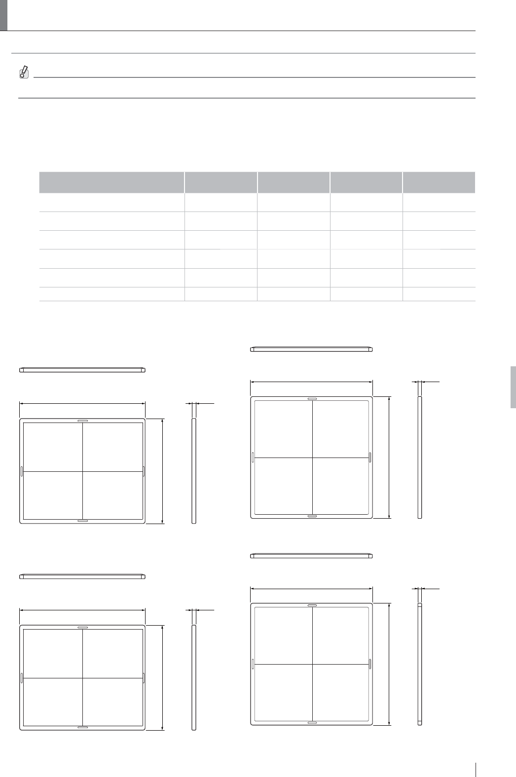
A-5
Appendix A Specifications
FDR D-EVO
II Operation Manual 897N120339A
$ ([WHUQDO9LHZDQG:HLJKW
The external view and weight of the FDR D-EVO II are shown below.
6SHFL¿FDWLRQVGLPHQVLRQVDQGZHLJKWDUHVXEMHFWWRFKDQJHIRULPSURYHPHQWZLWKRXWSULRUQRWLFH
A.2.1 DR-ID 1200
Ŷ '5,'38'5,''8
Width
(mm(in.)) Depth (mm(in.)) +HLJKW
(mm(in.))
:HLJKW
NJOE
Flat panel sensor (DR-ID 1201SE) 460(18.1) 384(15.1) 15(0.6) 2.6(5.8)*1
Flat panel sensor (DR-ID 1202SE) 460(18.1) 460(18.1) 15(0.6) 3.2(7.1)*1
Flat panel sensor (DR-ID 1211SE) 460(18.1) 384(15.1) 15(0.6) 2.6(5.8)*1
Flat panel sensor (DR-ID 1212SE) 460(18.1) 460(18.1) 15(0.6) 3.2(7.1)*1
Power supply unit 120(4.7) 388(15.3)*2361(14.2) 8.7(19.2)
Docking stand 579(22.8) 93(3.7) 202(8.0) 5.5(12.1)
*1 The weight of the battery pack is included.
*2 Protrusions are excluded
15(0.6)460(18.1)
384(15.1)
Flat panel sensor (DR-ID 1201SE)
15.5(0.6)459.9(18.1)
459.9(18.1)
Flat panel sensor (DR-ID 1202SE)
8QLWPPLQ
15.5(0.6)459.9(18.1)
459.9(18.1)
Flat panel sensor (DR-ID 1212SE)
15(0.6)460(18.1)
384(15.1)
Flat panel sensor (DR-ID 1211SE)
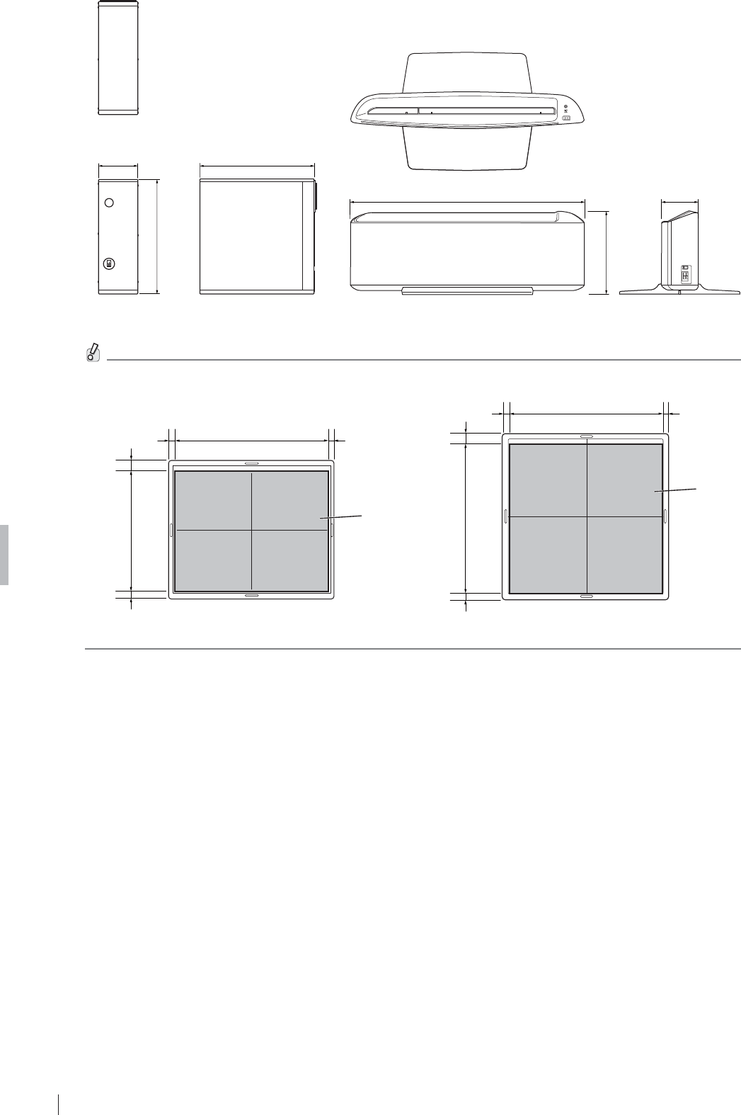
A-6
Appendix A Specifications
FDR D-EVO
II Operation Manual 897N120339A
581(22.9)
206.1(8.1)
93(3.7)
Docking stand
8QLWPPLQ
388(15.3)
120(4.7)
361(14.2)
Power supply unit
8QLWPPLQ
7KHHIIHFWLYHDUHDRIWKHÀDWSDQHOVHQVRULVDVVKRZQLQWKH¿JXUHEHORZ
Effective
area
425.4(16.7) 17.25
(0.68)
17.25
(0.68)
16.75
(0.66)
16.75
(0.66) 350.4(13.8)
425.4(16.7) 17.25
(0.68)
17.25
(0.68)
Effective
area
17.55
(0.69)
17.55
(0.69) 424.8(16.7)
DR-ID 1201SE/DR-ID 1211SE DR-ID 1202SE/DR-ID 1212SE
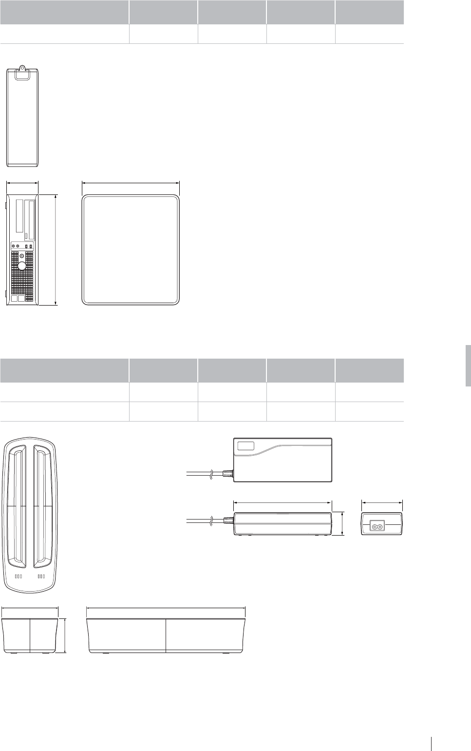
A-7
Appendix A Specifications
FDR D-EVO
II Operation Manual 897N120339A
Ŷ DR-ID 1200MC *
Width
(mm(in.)) Depth
(mm(in.))
+HLJKW
(mm(in.))
:HLJKW
NJOE
Control cabinet 114(4.5) 353(13.9) 399(15.7) 8.3(18.3)
* The exterior, external dimensions and weight are examples since this is a general-purpose electric device.
353(13.9)114(4.5)
399(15.7)
Control cabinet
8QLWPPLQ
Ŷ %DWWHU\FKDUJHURSWLRQDO
Width
(mm(in.)) Depth
(mm(in.))
+HLJKW
(mm(in.))
:HLJKW
NJOE
Battery charger 92.5(3.6) 259(10.2) 56(2.2) 0.6(1.3)
AC adapter 153(6.0) 67(2.6) 35(1.4) Approx.0.51(1.1)
153(6.0) 67(2.6)
35(1.4)
AC adapter
8QLWPPLQ
92.5 (3.6)
56(2.2)
259(10.2)
Battery charger

A-8
Appendix A Specifications
FDR D-EVO
II Operation Manual 897N120339A
Ŷ Access point (optional)
Width
(mm(in.)) Depth
(mm(in.))
+HLJKW
(mm(in.))
:HLJKW
NJOE
Access point 39(1.5) 95(3.7) 27(1.1) Less than approx.
0.1(0.2)
95(3.7) 27(1.1)
39(1.5)
8QLWPPLQ
Access point

A-9
Appendix A Specifications
FDR D-EVO
II Operation Manual 897N120339A
A.3 Characteristics
(1) Sensitometoric Response Characteristics and Dynamic Range
FDR D-EVO II has a linear response against the exposure range where it can depict the clinical information.
7KHÀDWSDQHOVHQVRUFRYHUVDG\QDPLFUDQJHRIȝ*\DWOHDVWDW54$
(2) Spatial Resolution Properties
A typical MTF value of DR-ID 1201SE/DR-ID 1202SE at 1cyc/mm, RQA5 is 0.75 (high sharpness mode)
and 0.60 (standard sharpness mode).
A typical MTF value of DR-ID 1211SE/DR-ID 1212SE at 1cyc/mm, RQA5 is 0.80.
The level of uncertainty is estimated as less than ±10%
'4('HWHFWLYH4XDQWXP(I¿FLHQF\
7\SLFDO'4(YDOXHRI'5,'6('5,'6(DWȝ*\LQF\FPPLV
7\SLFDO'4(YDOXHRI'5,'6('5,'6(DWȝ*\LQF\FPPLV
The level of uncertainty is estimated as less than ±10%
(4) Display
To deliver the detector characteristics above, it is recommended to use a monitor with the following
VSHFL¿FDWLRQV
Ɣ,PDJHPDWUL[VL]H0LQLPXP[SL[HOV'5,'6('5,'6(
Ɣ,PDJHPDWUL[VL]H0LQLPXP[SL[HOV'5,'6('5,'6(
Ɣ*UD\VFDOH0LQLPXPELW
Ɣ',&20FDOLEUDWHG
(5) Image Quality Evaluation
)XML¿OPW\SLFDOO\FRQGXFWVUHDGHUVWXGLHVWKDWFRPSDUHQHZ)'5'(92II detector models to chosen
PDUNHWHGGHYLFHV7KHVHVWXGLHVLQYROYLQJDQDVVHVVPHQWRILPDJHTXDOLW\E\ERDUGFHUWL¿HGUDGLRORJLVWV
have demonstrated that the images acquired using the FDR D-EVO II detectors are deemed to be of
diagnostic capability. Additionally, reader studies have concluded that, when used in conjunction with
FUJIFILM’s recommended exposure conditions as a reference, both the GOS-based and Csl-based FDR
D-EVO II detectors can provide acceptable diagnostic capability and image quality at reasonably low dose
levels typically used for pediatric use.
(6) Typical Patient Dose
$VZLWKDQ\QHZSURGXFWDSSOLFDWLRQ)XML¿OPSURYLGHVDSSOLFDWLRQVWUDLQLQJVXSSRUWWRHDFKFXVWRPHU
to establish the dose levels that meet the image quality standards of the medical facility. As part of this
training, we provide both recommended technique charts as well as guidance for optimizing AEC conditions
for each detector type. When using any FDR D-EVO II detector, typical patient dose levels should not
H[FHHGWKDWRIVFUHHQ¿OPRU&RPSXWHG5DGLRJUDSK\

A-10
Appendix A Specifications
FDR D-EVO
II Operation Manual 897N120339A

Z-1
Appendix Z Precautions for Exposure
FDR D-EVO
II Operation Manual 897N120339A
Appendix Z
Precautions for Exposure
Z.1
Precautions for Exposure in AUTO MODE
In AUTO MODE, stable image output can be obtained by means of the following.
5DGLDWLRQ¿HOG
(2) EDR image data analysis
(3) Detailed depiction of the cervical region
However, problems may arise due to differences in the multiple diaphragms or scattered rays of the
;UD\HTXLSPHQW)RUVXFKSUREOHPVFRQWDFWRXURI¿FLDOGHDOHURU)8-,),/05HSUHVHQWDWLYHDQGXVH
other recording modes, such as SEMI-AUTO MODE or FIX MODE.
Z.1.1 Radiation Field
1 'RQRWVHWWKHUDGLDWLRQ¿HOGH[WUHPHO\VPDOO%HVXUHWRVXEMHFWRQHWKLUGRUPRUHRIWKHOHQJWKRI
each side of the bucky of the DR system to X-ray exposure.
2 0DNHVXUHWKDWQRQHRIWKHVLGHVRIWKHUDGLDWLRQ¿HOGRYHUODSZLWKWKHFRQWUDVWPHGLXP(UURUVZLOO
result if they overlap.
$YDLODEOHIRU(DFK$QDWRPLFDO5HJLRQ0HWKRG
Plain Contrast Medium 7RPRJUDSK\
Head 4 4 4
1HFN 4 4 –
Chest 4 4 (1 for esophagus) –
Abdomen 4 4 (1 for stomach and intestines) –
Pelvis 4 4 –
3 Notes on PRIEF
[PRIEF 4] Used, with some exceptions, for both plain and contrast medium exposure menus,
from the head to the pelvis.
The diaphragm shape will be any convex polygon, including rectangles, circles,
ellipses, tracks, etc.
[PRIEF 1] Used with esophagus, stomach and intestines contrast medium menus.
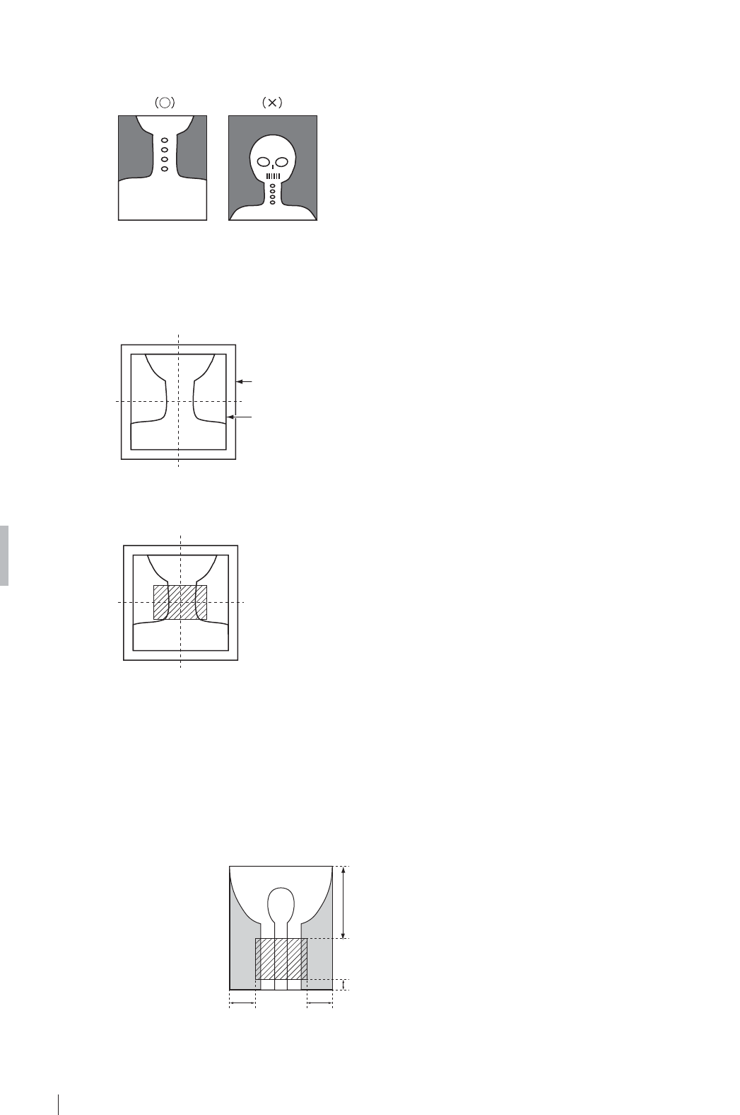
Z-2
Appendix Z Precautions for Exposure
FDR D-EVO
II Operation Manual 897N120339A
= 'HSLFWLRQRIWKH&HUYLFDO5HJLRQ
1 7KHUDGLDWLRQ¿HOGPXVWQRWLQFOXGHWKHZKROHKHDG%HVXUHWRVHFXUHWUDQVSDUHQWSRUWLRQVRQERWK
sides of the neck.
8VHWKH³+HDG´PHQXWRLQFOXGHWKHZKROHKHDGLQWKHUDGLDWLRQ¿HOG
2 )RUH[SRVXUHRIWKHSKDU\Q[RUODU\Q[EHVXUHWKDWWKHQHFNFRPHVWRWKHFHQWHURIWKHUDGLDWLRQ¿HOG
so that the frontal and lateral orientations can be recognized appropriately.
Image area
Radiation field
3 In pharynx and/or larynx exposure, do not use lead characters in the oblique line section.
= 'HSLFWLRQRIWKH+,3-2,17$;/±0HQX
1 Make sure to position the region of interest within the slanted-line area shown below.
Do not collimate further inside.
2 Positioning should be done so that the condyle and the femur run along the longer edge. (Do not
position them against the shorter edge.)
7/12
1/12
1/41/4
Condyle side
Femur side

Z-3
Appendix Z Precautions for Exposure
FDR D-EVO
II Operation Manual 897N120339A
= ('5,PDJH'DWD$QDO\VLV
1 Image unevenness due to grid misalignment, X-ray beam misalignment, or shadow of clothes may
cause EDR image data analysis problems resulting in unstable density on the image.
2 If the target includes such materials as gypsum, denture, etc., stable density may not be obtained,
EHFDXVHVXFKPDWHULDOVPDNHLWGLI¿FXOWWRDQDO\]H('5LPDJHGDWD
In such cases, use FIX MODE.
3 The EDR performs processing for the image area trimmed by the DR system.
:KHQXVLQJOHDGFKDUDFWHUVRUPHWDOVIRUPHDVXUHPHQWSODFHWKHPLQVLGHWKHUDGLDWLRQ¿HOGDQG
then make an exposure.
4 Precautions when using AUTO MODE.
Auto mode Precautions
I As this mode is available for extracting information on the skin, secure the positioning so
that the direct X-rays are incident to an area other than the target.
II No special precautions.
III Be sure to use a Ba contrast medium.
IV
1 Be sure to secure the positioning so that the X-rays are incident to the area directly
outside the target.
$VWKHUHDGLQJODWLWXGHLV¿[HGLWLVQHFHVVDU\WRFRQWUROWKHWXEHYROWDJHDFFRUGLQJWRWKH
thickness of the target, as usual.
V $VWKHUHDGLQJODWLWXGHLV¿[HGLWLVQHFHVVDU\WRFRQWUROWKHWXEHYROWDJHDFFRUGLQJWRWKH
thickness of the target, as usual.
VI No special precautions.
VII No special precautions.
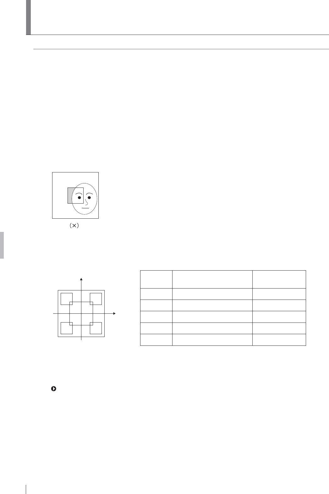
Z-4
Appendix Z Precautions for Exposure
FDR D-EVO
II Operation Manual 897N120339A
Z.2 Precautions for Exposure in SEMI-
AUTO MODE
These precautions are common to Semi I, II, III and III(**).
1 Position the portion you need to display often in the center areas (10cm × 10cm(3.9 in. × 3.9 in.)
(Semi I), 7cm × 7cm(2.8 in. × 2.8 in.) (Semi II), 5cm × 5cm(2.0 in. × 2.0 in.) (Semi III)) of the images
trimmed by the DR system.
Position the portion you need to display often in each of the 5cm × 5cm(2.0 in. × 2.0 in.) center
areas of the half-split images (both upper and lower halves and right and left halves) and quarter-
split image trimmed by the DR system.
2 Never position anything other than the subject in the aforementioned areas. If anything other than
the subject is positioned in such areas, the image density will become lower.
,QDGGLWLRQGRQRWSRVLWLRQDQ\PHWDOVRUDUWL¿FLDOERQHVLQVXFKDUHDV7KHLPDJHGHQVLW\ZLOO
become higher if such objects are positioned in these areas.
3 It is necessary to control tube voltage according to subject thickness, as usual.
The following precautions should be observed for Semi IV.
a
bc
de
y
x
Area Center Coordinate
(x:y) cm(in.) Size (cm(in.))
a (0(0), 0(0)) 10 × 10(3.9 × 3.9)
b (-5(-2.0), 7(2.8)) 6 × 6(2.4 × 2.4)
c (5(2.0), 7(2.8)) 6 × 6(2.4 × 2.4)
d (-5(-2.0), -7(-2.8)) 6 × 6(2.4 × 2.4)
e (5(2.0), -7(-2.8)) 6 × 6(2.4 × 2.4)
'RQRWSRVLWLRQWUDQVSDUHQWSRUWLRQVDUHDVRWKHUWKDQWKHVXEMHFWLQWKHDIRUHPHQWLRQHG¿YH
areas.
(2) It is necessary to control tube voltage according to subject thickness, as usual.
For details of the menus preset in SEMI-AUTO MODE, see the “DR-ID 300CL Operation Manual”
and “DR-ID 300CL Reference Guide (Image Processing Parameters)”.

Z-5
Appendix Z Precautions for Exposure
FDR D-EVO
II Operation Manual 897N120339A
= 3UHFDXWLRQVIRU([SRVXUHLQ6(0,;
MODE
The user will select one of the nine areas of the image trimmed by the DR system, on which SEMI-
AUTO MODE applies. (See the illustration below.)
The same precautions as for SEMI-AUTO MODE apply.
LCR
T
M
B
5cm × 5cm
(2.0 in. × 2.0 in.)

Z-6
Appendix Z Precautions for Exposure
FDR D-EVO
II Operation Manual 897N120339A
= 3UHFDXWLRQVIRU([SRVXUHLQ),;02'(
$VUHDGLQJFRQGLWLRQVDUH¿[HGH[SRVXUHFRQGLWLRQVPXVWEHFRQWUROOHGLQWKHVDPHZD\DVIRU
conventional X-ray exposure.
The reading conditions (sensitivity and latitude) have been preset according to the relevant menu in
FIX MODE. Select the exposure conditions which correspond to that menu accordingly.

Z-7
Appendix Z Precautions for Exposure
FDR D-EVO
II Operation Manual 897N120339A
= 3UHFDXWLRQVIRUWKH$XWRPDWLF;UD\
Detection Function
= 3UHFDXWLRQVIRU0DNLQJDQ([SRVXUH
1 7KHÀDWSDQHOVHQVRUFDQQRWGHWHFW;UD\VDXWRPDWLFDOO\XQOHVV6KRW5HDG\H[SRVXUHUHDG\VWDWXV
LQGLFDWRURQWKHLPDJHSURFHVVLQJXQLWWKH5($'<ODPSDPRQJWKHVWDWXVODPSVRQWKHÀDWSDQHO
sensor, or the READY lamp on the docking stand is lit green. Even if the indicator is not lit green,
radiation can be delivered but an image will not be output. Make sure that the indicator is lit green
before making an exposure.
2 Check the tube current of the X-ray equipment in advance, and set exposure conditions based
on the tube current by referring to the table below. If the conditions are not met, X-rays cannot be
detected automatically and an image may not be acquired.
Tube current Tube voltage Exposure
time
SID 5DGLDWLRQ¿HOG
More than
40 mA
Set the tube voltage
according to the
anatomical region
and body thickness.
More than
1 ms
(*3)
Set the SID according to
the anatomical region.
Do not limit the radiation
¿HOGWRWKHERQHUHJLRQ
(*1) only.
More than
20 mA and less
than 40 mA
Set the tube voltage
to more than 50 kV
according to the
anatomical region
and body thickness.
Set the SID to 100 cm (39.4 in.) or less and do not
OLPLWWKHUDGLDWLRQ¿HOGWRWKHERQHUHJLRQRQO\
Alternatively, set the SID according to the anatomical
region and include the directly exposed area (*2).
More than
10 mA and less
than 20 mA
100 cm (39.4 in.) or less Include the directly
exposed area (*2).
Less than
10 mA
The automatic X-ray detection function cannot be used.
:KHQPDNLQJDQH[SRVXUHIRUH[DPSOHIRUD¿QJHURUNQHHVHWWKHUDGLDWLRQ¿HOGWRDWOHDVWFPîFP
LQîLQIRUWKHIRUPHUDQGDWOHDVWFPîFPLQîLQIRUWKHODWWHUVRWKDWWKH¿HOGLV
not limited to the bone region only.
7KHDUHDVRIWKHÀDWSDQHOVHQVRUZKLFKDUHGLUHFWO\H[SRVHGWR;UD\VWKDWGRQRWSDVVWKURXJKWKH
subject, must have a width of more than 3 cm (1.2 in.) from the subject.
*3 Depending on the X-ray equipment, the actual exposure time may differ from the set time. Before use,
PDNHVXUHWKDWWKHÀDWSDQHOVHQVRUFDQGHWHFW;UD\VDXWRPDWLFDOO\
3 As illustrated below, if the subject whose thinnest part is at least 40 cm (15.7 in.) in thickness
FRYHUVWKHHQWLUHVXUIDFHRIWKHÀDWSDQHOVHQVRULWFDQQRWGHWHFW;UD\VDXWRPDWLFDOO\DQGDQ
image may not be acquired. In this case, make an exposure for the region including the directly
exposed area or switch to the High Sensitivity Mode. While the high sensitivity mode is being set,
a shock might cause a blank image.
Figure of an exposure for the subject covering the entire surface of the flat panel sensor

Z-8
Appendix Z Precautions for Exposure
FDR D-EVO
II Operation Manual 897N120339A
4 :KHQDQH[SRVXUHPHQXLVUHJLVWHUHGDQGWKHV\VWHPLVUHDG\IRUDQH[SRVXUHWKHÀDWSDQHO
sensor enters X-ray detection mode. If an exposure is not made for a period of time while an
H[SRVXUHPHQXLVUHJLVWHUHGWKHRSHUDWLQJWLPHRIWKHÀDWSDQHOVHQVRU¶VEDWWHU\SDFNPD\EH
reduced to half. In addition, the battery pack cannot be charged with an exposure menu registered,
HYHQLIWKHÀDWSDQHOVHQVRUKDVDZLUHGFRQQHFWLRQ)RUWKHVHUHDVRQVGRQRWNHHSWKHV\VWHPRQ
standby, unless you make an exposure.
= 3UHFDXWLRQV5HODWHGWRWKH;UD\([SRVXUH7LPH
:KHQGHOLYHULQJUDGLDWLRQGRQRWVHWWKHH[SRVXUHWLPHEH\RQGWKHPD[LPXPOLPLWVSHFL¿HGIRUWKH
ÀDWSDQHOVHQVRUDWWKHWLPHRILQVWDOODWLRQ2WKHUZLVHYHUWLFDODUWLIDFWVPD\DSSHDULQWKHLPDJH
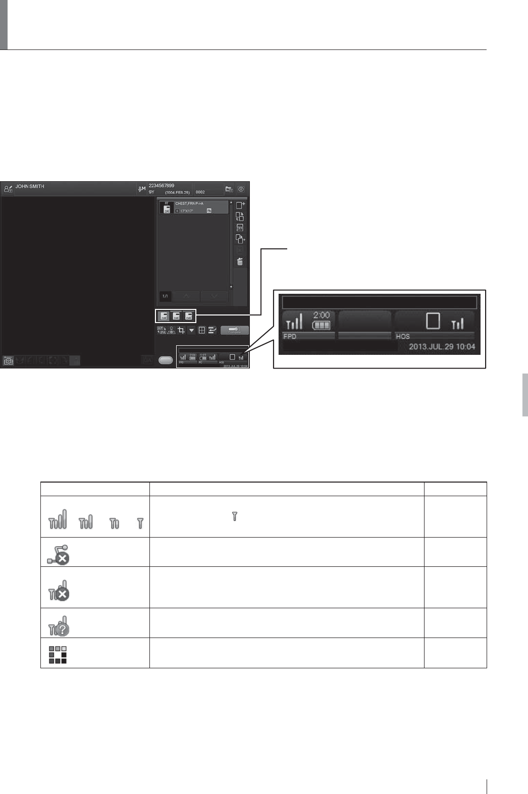
Z-9
Appendix Z Precautions for Exposure
FDR D-EVO
II Operation Manual 897N120339A
Z.6 Precautions for Use in Wireless
Communication Mode
Care should be taken when the devices are used in wireless communication mode. Thoroughly read
the following precautions in order to use the devices properly.
Ŷ,FRQV'LVSOD\HGRQWKH,PDJH3URFHVVLQJ8QLW
An icon indicating the status of wireless communication is displayed in the connected devices status
at the lower right of the image processing unit display. Before an exposure is made, check the
displayed icon to make sure that proper wireless communication is established.
Connected devices status
(2)(1)
* The following display order is an example.
([SRVXUHXQLWGLVSOD\¿HOG
(1) Exposure unit communication indicator
7KHZLUHOHVVFRPPXQLFDWLRQVWDWXVRIWKHÀDWSDQHOVHQVRUDVVLJQHGWRWKHVHOHFWRULVGLVSOD\HG
(2) Hospital wireless communication indicator
Displays the status of wireless communication between the image processing unit and the in-
hospital LAN.
Details on the icons regarding wireless communication displayed in the areas (1) and (2) are as follows.
Icon Description Display Area
/ / /
Communication is established. The radio wave strength is displayed
in four levels. While is displayed, wireless communication or
image transfer to the hospital LAN becomes unstable.
(1) and (2)
([SRVXUHLVQRWDYDLODEOH&RPPXQLFDWLRQZLWKWKHÀDWSDQHO
sensor is disconnected.) (1)
Wireless communication is not available. (Since the radio wave
strength is weak, wireless communication cannot be used. If this
icon is displayed in the area (1), exposures cannot be made.)
(1) and (2)
Information on the radio wave strength is being received. (1)
The in-hospital LAN connection is being switched. (2)
For details on other icons, see the “Console Advance (DR-ID 300CL) Reference Guide”.

Z-10
Appendix Z Precautions for Exposure
FDR D-EVO
II Operation Manual 897N120339A
Z.7 Other Precautions
Z.7.1 Precautions for Exposure of a Subject in Relatively
/DUJH&RQWUDVW
1 Exposures using a contrast medium may cause artifacts around it.
2 When exposing a subject with any metal objects implanted, artifacts may appear around them.
3 For exposures with objects of large X-ray absorption, such as lead characters and metals for
measurement, artifacts may appear around them. Place such objects outside a subject.
Z.7.2 Precautions for Flat Panel Sensor
*HQHUDOO\ZKHQSHUIRUPLQJDKLJKVHQVLWLYLW\H[SRVXUHVKRUWO\DIWHUDQH[SRVXUHWKDWWKHÀDW
panel sensor excessively receives direct X-ray, the output image may contain image lags of the
previous exposure. This phenomenon rarely occurs and does not occur insofar as normal sensitivity
exposures are performed.
Exposures at longer intervals can reduce occurrences of this phenomenon. Also observe
precautions as follows.
• Continuous high sensitivity exposures to vertebral body part (chest/lumbar spine) should be
performed at longer intervals than normal exposures.
$KLJKVHQVLWLYLW\H[SRVXUHVKRUWO\DIWHUDKLJKGRVHH[SRVXUHVKRXOGEHSHUIRUPHGDWVXI¿FLHQWO\
long interval.
:KHQSHUIRUPLQJKLJKGRVHH[SRVXUHVUHSHDWHGO\GRQRWXVHFROOLPDWLRQRIWKHUDGLDWLRQ¿HOG
lead characters or metals for measurement at the same position.
= 3UHFDXWLRQVIRU$VVXULQJWKH5DGLDWLRQ)LHOG
CAUTIONS
Ɣ ,WLVLPSRUWDQWWRUHDGWKHIROORZLQJEHIRUHXVLQJWKH)'5'(92IIGLJLWDOGHWHFWRUFOLQLFDOO\
Ɣ 'RQRWPDNHWKHUDGLDWLRQ¿HOGODUJHUWKDQWKHVL]HRIWKHÀDWSDQHOVHQVRU(VSHFLDOO\ZKHQ
WKHKLJKWXEHYROWDJHLVVHWWKHUDGLDWLRQ¿HOGVL]HVKRXOGQRWEHODUJHUWKDQWKHVXEMHFW
unless necessary.
The FDR D-EVO II is a digital X-ray detector designed for use both within and outside of a standard
UDGLRJUDSKLFEXFN\5DGLDWLRQ¿HOGFDQEHVHWXSWR´î´'5,'6('5,'6(RUXS
to 17” × 17” (DR-ID 1202SE/DR-ID1212SE) and this product may be used with the X-ray equipment
LQDQ\VLWXDWLRQZKHUHD¿OPFDVVHWWHPD\EHXVHG
The collimator will open up to 14”× 17” for DR-ID 1201SE/DR-ID 1211SE and 17”× 17” for DR-ID
1202SE/DR-ID 1212SE, when the FDR D-EVO II cassette is inserted in the bucky tray of the X-ray
equipment with positive beam limitation (PBL).
)ROORZWKH;UD\V\VWHPPDQXIDFWXUHU¶VLQVWUXFWLRQVWRDVVXUHWKHLQGLFDWHG¿HOGVL]HPDWFKHVDQG
GRHVQRWH[FHHGWKHDFWXDOUDGLDWLRQ¿HOGVL]HIRUWKHDYDLODEOHUDQJHRI6,'V
= ,PDJHV2XWSXW:KHQWKH;UD\6KRW6ZLWFKLV2SHUDWHG
Incorrectly
In case that you press the X-ray shot switch only momentarily after selecting exposure menus,
VXI¿FLHQW;UD\GRVHPD\QRWEHDFKLHYHG7KHRXWSXWLPDJHFRQWDLQVLPDJHODJVRIWKHSUHYLRXV
exposure occasionally.
If this happens, select exposure menus again, and then make an exposure.

Z-11
Appendix Z Precautions for Exposure
FDR D-EVO
II Operation Manual 897N120339A
= 3UHFDXWLRQVIRU8UJHQW8VH
When you start a study before completion of the calibration at the time of startup, the operation will
be in Urgent Use Mode. At this time, “Urgent use is possible” appears in the “Output Device Status
window” of the image processing unit.
• There is no guarantee that the image taken in Urgent Use Mode can be used for diagnostic
purposes. Vertical artifact could appear in the image, if the temperature difference is large from
the previous shutdown of the system. Check the image quality before use.
• Move from the Study Screen to the Patient Information Input Screen immediately after exiting
Urgent Use Mode, so that the calibration will start over automatically.
Z.7.6 Precautions Related to Continuous Operation
If you plan to continuously run the system for over 24 hours, perform post-operation check, and
then restart the system.
Otherwise, calibration will not be performed normally, and image quality cannot be guaranteed as a
result.
Z.7.7 Precautions Related to Grid
Depending on the type of the grid used, its stripes may appear in the image after making an
exposure. To avoid such moire effects, sway the grid from side to side, or use the Grid Pattern
Removal Processing Software in conjunction with the grid with 40 lines.
= 3UHFDXWLRQVGXULQJ&DOLEUDWLRQ
2EVHUYHWKHIROORZLQJZKHQWKH5($'<VWDWXVODPSRQWKHÀDWSDQHOVHQVRULVEOLQNLQJRUZKHQWKH
message “Calibrating...” is displayed on the image processing unit.
'RQRWVXEMHFWWKHÀDWSDQHOVHQVRUWRVKRFN
• Do not deliver radiation.
'RQRWFRQQHFWGLVFRQQHFWWKHÀDWSDQHOVHQVRUWRIURPWKHSRZHUVXSSO\XQLWRUWRIURPWKH
docking stand.
= 3UHFDXWLRQVIRU([SRVLQJWKH)ODW3DQHO6HQVRUWR;UD\
:KHQ\RXH[SRVHWKHÀDWSDQHOVHQVRUWR;UD\DWDQ\RWKHUWLPHH[FHSWGXULQJUDGLRJUDSK\
artifacts could appear in the image. If artifacts appeared in the image due to X-ray irradiation,
perform a test X-ray radiography after waiting for more than 2 minutes and then restart exposure
DIWHUFRQ¿UPLQJWKDWWKHDUWLIDFWVGLVDSSHDU
=3UHFDXWLRQVIRU([WHQGHG,PDJH5HDGRXW
,IDQ\LPSDFWLVDSSOLHGWRWKHÀDWSDQHOVHQVRUZKLOHDQLPDJHLVEHLQJDFTXLUHGZLWK([WHQGHG
,PDJH5HDGRXWDUWLIDFWVPD\DSSHDULQWKHLPDJH%HIRUHUHPRYLQJWKHÀDWSDQHOVHQVRUIURPWKH
radiographic examination stand, be sure to check the acquired image on the image processing unit.
In addition, note that when Extended Image Readout is enabled, the system cannot be used in an
emergency since the system start-up time becomes longer.

Z-12
Appendix Z Precautions for Exposure
FDR D-EVO
II Operation Manual 897N120339A
=3UHFDXWLRQVIRU8VLQJWKH$FFHVV3RLQW
When making an exposure with the access point, do not remove the USB cable until the image
appears on the image processing unit and ShotReady lights green.
Also, with the supplied Velcro tape and clamp or by other means, secure the USB cable before use
to prevent it from being disconnected accidentally.

O-1
Appendix O Use of Optional Items
FDR D-EVO
II Operation Manual 897N120339A
Appendix O Use of Optional Items
O.1 Optional Items
Name Description
SE storage case $FDVHXVHGIRUFDUU\LQJDQGVWRULQJWKHÀDWSDQHOVHQVRU
For the external view and precautions, see “O.2 Using the SE Storage
Case” (page O-2).
Battery pack $EDWWHU\SDFNIRUWKHÀDWSDQHOVHQVRU
For precautions, charging and installing/removing, see pages 1-8, 1-9, 3-6,
3-7 and 3-8.
Battery charger A battery charger for the battery pack.
For precautions, external view and charging, see pages 1-8, 1-9, 2-5, 3-6
and 3-7.
Retaining bracket for MP $VHWRIDQDQFKRUDQGD¿[WXUHZKLFKLVXVHGIRUVHFXULQJWKHSRZHUVXSSO\
XQLWWRWKHÀRRU
For the external view, see “O.3 Using the Retaining bracket for MP” (page
O-3).
SE cable $FDEOHWKDWFRQQHFWVWKHÀDWSDQHOVHQVRUDQGWKHSRZHUVXSSO\XQLW
7KLVFDEOHLVXVHGIRUDGGLQJWKHVHFRQGDQGVXEVHTXHQWÀDWSDQHO
VHQVRUVFKDQJLQJRYHUWKHFRQQHFWLRQEHWZHHQWKHÀDWSDQHOVHQVRUVDQG
other usages.
Relay unit for AC bucky A relay unit consisting of the relay and terminal block for the AC bucky.
)RXUW\SHVDUHDYDLODEOH)RU999DQG9
0DJQHWLFFODPSIRUÀDWSDQHO
sensor cable
$FODPSIRU¿[LQJWKH6(FDEOHWRWKHUDGLRJUDSKLFH[DPLQDWLRQVWDQGHWF
Adapter for the docking stand $QDGDSWHUXVHGIRUDWWDFKLQJWKHÀDWSDQHOVHQVRUWRWKHGRFNLQJVWDQG
DS Anchor Fixing Bracket $QDQFKRUDQG¿[LQJWRROVHWXVHGIRU¿[LQJWKHGRFNLQJVWDQGWRWKHÀRRU
For the external view, see “O.4 DS Anchor Fixing Bracket” (page O-4).
Wall Fixing Bracket $QDQFKRUDQG¿[LQJWRROVHWXVHGIRU¿[LQJWKHGRFNLQJVWDQGWRWKHÀRRU
For the external view, see “O.5 Wall Fixing Bracket” (page O-5).
SE communication cable
$FDEOHXVHGIRUFRQQHFWLQJWKHÀDWSDQHOVHQVRUDQGWKHRSWLRQDODFFHVVSRLQW
This cable is used for wired communication if wireless communication is not
available.
,QDGGLWLRQWKLVFDEOHLVXVHGIRUUHJLVWHULQJRUUHFRJQL]LQJWKHÀDWSDQHOVHQVRU
&DEOHOHQJWK$SSUR[PIW
Access point
$QDFFHVVSRLQWXVHGIRUZLUHOHVVFRPPXQLFDWLRQEHWZHHQWKHÀDWSDQHOVHQVRU
and the image processing unit.
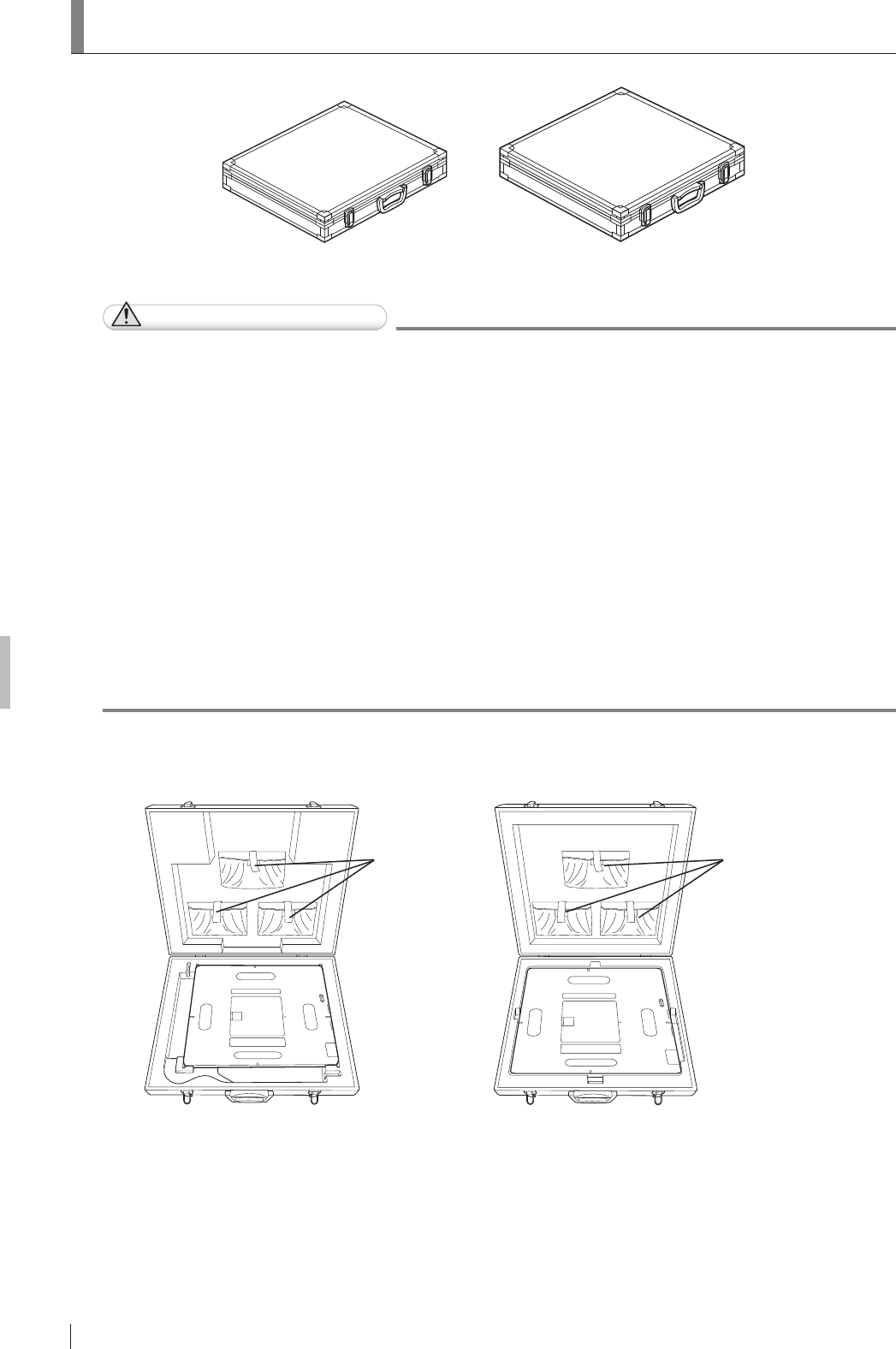
O-2
Appendix O Use of Optional Items
FDR D-EVO
II Operation Manual 897N120339A
28VLQJWKH6(6WRUDJH&DVH
SE storage case for 35
(DR-ID 1201SE/DR-ID 1211SE)
SE storage case for 43
(DR-ID 1202SE/DR-ID 1212SE)
CAUTIONS
Ɣ 'RQRWVWRUHWKH6(VWRUDJHFDVHLQDORFDWLRQZLWKWKHIROORZLQJFRQGLWLRQV
Ɣ:KHUHWKH6(VWRUDJHFDVHLVH[SRVHGWRGLUHFWVXQOLJKW
Ɣ:KHUHWKHWHPSHUDWXUHDQGKXPLGLW\FKDQJHGUDPDWLFDOO\
Ɣ:KHUHWKHUHLVH[FHVVLYHGXVW
Ɣ:KHUHFKHPLFDOVDUHVWRUHG
Ɣ:KHUHWKH6(VWRUDJHFDVHPD\EHH[SRVHGWRZDWHUGXHWRZDWHUOHDNDJHRULQJUHVV
Ɣ 6WRUHWKHÀDWSDQHOVHQVRUDQGWKHFDEOHSURSHUO\LQWKH6(VWRUDJHFDVH
2WKHUZLVHWKH\PD\EHFDXJKWXQGHUWKHFDVHOLGDQGGDPDJHG
Ɣ 'RQRWFRQQHFWWKHÀDWSDQHOVHQVRUWRWKH6(FDEOHRU6(FRPPXQLFDWLRQFDEOHZKLOHLWLV
VWRUHGLQWKH6(VWRUDJHFDVH
Ɣ 'RQRWVWRUHDQ\WKLQJRWKHUWKDQWKHÀDWSDQHOVHQVRULQWKH6(VWRUDJHFDVH
Ɣ &DUHIXOO\FDUU\WKH6(VWRUDJHFDVHZKHQWKHÀDWSDQHOVHQVRULVLQVLGH
Ɣ 7KH6(VWRUDJHFDVHDQGRUWKHÀDWSDQHOVHQVRULQVLGHPD\EHGDPDJHGLIWKHFDVHLV
subject to an impact.
Ɣ 'RQRWRSHQFORVHWKH6(VWRUDJHFDVHLQDORFDWLRQZKHUHWKHUHLVH[FHVVLYHGXVWRUGLUW
Ɣ
'RQRWSXWWKH6(VWRUDJHFDVHRQDQXQVWDEOHSODFH,ILWIDOOVRUGURSVSHUVRQDOLQMXU\PD\UHVXOW
Ɣ %HFDUHIXOQRWWRKDYH\RXUKDQGRUDQREMHFWFDXJKWZKHQFORVLQJWKH6(VWRUDJHFDVH
:KHQVWRULQJWKHÀDWSDQHOVHQVRULQWKH6(VWRUDJHFDVHSODFHLWZLWKWKHH[SRVXUHSODQHGRZQ
For details, see the illustrations below.
Battery holder
pockets
SE storage case for 43
(DR-ID 1202SE/DR-ID 1212SE)
Battery holder
pockets
SE storage case for 35
(DR-ID 1201SE/DR-ID 1211SE)

O-3
Appendix O Use of Optional Items
FDR D-EVO
II Operation Manual 897N120339A
28VLQJWKH5HWDLQLQJ%UDFNHWIRU03
&RQWDFWD)8-,),/0GHDOHUIRULQVWDOODWLRQRIWKH5HWDLQLQJEUDFNHWIRU03

O-4
Appendix O Use of Optional Items
FDR D-EVO
II Operation Manual 897N120339A
2'6$QFKRU)L[LQJ%UDFNHW
&RQWDFWD)8-,),/0GHDOHUIRULQVWDOODWLRQRIWKH'6DQFKRU¿[LQJEUDFNHW

O-5
Appendix O Use of Optional Items
FDR D-EVO
II Operation Manual 897N120339A
2:DOO)L[LQJ%UDFNHW
&RQWDFWD)8-,),/0GHDOHUIRULQVWDOODWLRQRIWKHZDOO¿[LQJEUDFNHW

O-6
Appendix O Use of Optional Items
O
II Operation Manual 897N120339A
O.6 Access Point
Precautions for Use
CAUTIONS
Ɣ7KH$FFHVV3RLQWLQFRUSRUDWHVDZLUHOHVVGHYLFHWKDWFRPSOLHVZLWKWKHWHFKQLFDOVWDQGDUGV
Do not disassemble or modify the Access Point.
In addition, do not remove the name plate attached to this product. If the name plate is not
attached, use of this product is prohibited.
Ɣ8VHRIWKH$FFHVV3RLQWLVDOORZHGLQWKHDUHDRISXUFKDVH
Ɣ0DNHVXUHWKDWWKHUHDUHQRVKLHOGLQJPDWHULDOVEHWZHHQWKH$FFHVV3RLQWDQGWKHFRPPXQLFDWLRQ
device. For example, if there is a metal plate or concrete wall between them, wireless
communication may not be available. In addition, do not cover the plane with the status lamps.
Ɣ'RQRWXVHWKH$FFHVV3RLQWQHDUWKHIROORZLQJGHYLFHV
,QGXVWULDOVFLHQWL¿FDQGPHGLFDOHTXLSPHQWVXFKDVDPLFURZDYHRYHQSDFHPDNHUHWF
-
/RFDOSULYDWHUDGLRVWDWLRQVIRUPRELOHREMHFWLGHQWL¿FDWLRQXVHGLQIDFWRU\SURGXFWLRQOLQHVHWF
UDGLRVWDWLRQVUHTXLULQJDOLFHQVH
6SHFL¿HGORZSRZHUUDGLRVWDWLRQVUDGLRVWDWLRQVUHTXLULQJQROLFHQVH
Ɣ'RQRWXVHWKH$FFHVV3RLQWQHDUUDGLRVWHOHYLVLRQVPRELOHSKRQHVRU3+6SKRQHVDVIDUDV
possible. If these devices are placed near the wireless LAN products, audio or video noise may
RFFXUGXHWRHOHFWURPDJQHWLFZDYHVJHQHUDWHGIURPWKHZLUHOHVV/$1SURGXFWVLQFOXGLQJWKH
Access Point.
Ɣ'RQRWXVHWKH$FFHVV3RLQWQHDUDKHDWVRXUFH,QDGGLWLRQGRQRWFRYHUWKHYHQWLODWLRQKROHV
Ɣ'RQRWDOORZWKH$FFHVV3RLQWJHWZHWRUGXVW\
Ɣ7DNHFDUHQRWWRWULSRYHUWKHFDEOH,IWKHFDEOHLVGLVFRQQHFWHGRUDOPRVWGLVFRQQHFWHG
wireless communication may not be established.
Ɣ'RQRWVXEMHFWWKH$FFHVV3RLQWWRVHYHUHVKRFNE\GURSSLQJLWHWF
Ɣ:KHQXVLQJWKH$FFHVV3RLQWSODFHLWDWOHDVWFPLQDZD\IURPWKHERG\
Ɣ7RVXSSO\SRZHUWRWKH$FFHVV3RLQWFRQQHFWLWWRWKH)8-,),/0VSHFL¿HGSHUVRQDOFRPSXWHU
VXSSRUWLQJ86%
Ɣ
8VHWKH$FFHVV3RLQWE\FRQQHFWLQJLWWRWKHSUHVHWLPDJHSURFHVVLQJXQLWDQGWRWKH86%
connector.
Ɣ'LUHFWO\FRQQHFWWKH$FFHVV3RLQWDQGWKHLPDJHSURFHVVLQJXQLWRQO\ZLWKWKHVXSSOLHG86%
cable. Do not use a hub for connection.
Ɣ'RQRWGHOHWHRUFKDQJHWKH86%GULYHULQVWDOOHGLQWKHLPDJHSURFHVVLQJXQLW
Ɣ'RQRWSODFHWKHVXSSOLHG9HOFURWDSHRYHUWKH$FFHVV3RLQW3URGXFW/DEHODQG$FFHVV3RLQW
5DGLR/DZ&HUWL¿FDWLRQ/DEHO

O-7
Appendix O Use of Optional Items
FDR D-EVO
II Operation Manual 897N120339A
Precautions for LAN Connection
CAUTIONS
Ɣ)RUWKH/$1FRQQHFWLRQXVHWKHGHGLFDWHG/$1FRQYHUVLRQFDEOH,QDGGLWLRQZKHQFRQQHFWLQJ
RUGLVFRQQHFWLQJWKH/$1FRQYHUVLRQFDEOHEHVXUHWRKROGWKHFRQQHFWRUSRUWLRQ
,ILWLVFRQQHFWHGRUGLVFRQQHFWHGZKLOHKROGLQJWKHFDEOHWKHFDEOHPD\EHEURNHQ
Ɣ5DGLRZDYHVDYDLODEOHRXWGRRUVYDU\GHSHQGLQJRQWKHFRXQWU\ZKHUHWKHV\VWHPLVXVHG
(For U.S.)
5DGLRZDYHVLQWKH*+]IUHTXHQF\EDQGFDQEHXVHGLQGRRUVRQO\
:KHQUDGLRZDYHVLQWKH*+]DQG*+]IUHTXHQF\EDQGVDUHVHOHFWHGWKH')6IXQFWLRQZLOO
operate.
Ɣ:KHQWKH$FFHVV3RLQWDQGDSHUVRQDOFRPSXWHULVFRQQHFWHGXVLQJWKH86%FDEOHGRQRW
connect the Access Point and the personal computer via the LAN connection.
3UHFDXWLRQVIRU8VLQJWKH')6'\QDPLF)UHTXHQF\6HOHFWLRQ)XQFWLRQ
CAUTIONS
Ɣ7KH$FFHVV3RLQWVXSSRUWVWKH')6IXQFWLRQFRQIRUPLQJWR,(((Q,IDUDGDUZDYHLV
GHWHFWHGZKLOHVHWWLQJDFKDQQHOWKHFKDQQHOPD\EHFKDQJHGDXWRPDWLFDOO\LQRUGHUWRDYRLG
interference to weather radar, etc.
Ɣ'XULQJVWDUWXSWKH$FFHVV3RLQWFKHFNVLIWKHUHDUHDQ\UDGDUZDYHV:KLOHWKHFKHFNLVLQ
SURJUHVVFRPPXQLFDWLRQZLWKWKH$FFHVV3RLQWLVQRWDYDLODEOH
Ɣ,IDUDGDUZDYHLVGHWHFWHGWKHUDGDUZDYHLVPRQLWRUHGIRUDVSHFL¿HGWLPHDERXWPLQXWH
:KLOHPRQLWRULQJWKHUDGDUZDYHZLUHOHVVFRPPXQLFDWLRQLVQRWDYDLODEOH,QDGGLWLRQDERXW
PLQXWHVDUHUHTXLUHGXQWLOWKHFKDQQHOLQZKLFKDUDGDUZDYHZDVGHWHFWHGEHFRPHVDYDLODEOH
For details of the access point, see “Access point Operation Manual”.

O-8
Appendix O Use of Optional Items
O
II Operation Manual 897N120339A

Maintenance and Inspection
FDR D-EVO
II Operation Manual 897N120339A
Maintenance and Inspection
0DLQWHQDQFHDQG,QVSHFWLRQ,WHPV$VVLJQHGWR6SHFL¿HG'HDOHU
)RUSHULRGLFDOLQVSHFWLRQRIWKHHTXLSPHQWDQGQHFHVVDU\DUUDQJHPHQWVFRQVXOWRXURI¿FLDOGHDOHU
or local representative.
Periodical Maintenance
0DNHVXUHWKDWWKHSHULRGLFDOPDLQWHQDQFHDQGLQVSHFWLRQDVVLJQHGWRRXURI¿FLDOGHDOHURU
)8-,),/05HSUHVHQWDWLYHDUHSHUIRUPHGDVVSHFL¿HG
0DLQWHQDQFHDQG,QVSHFWLRQ,WHPV$VVLJQHGWR6SHFL¿HG'HDOHU
Periodical Maintenance and Inspection Items Period
Checking of the image Every year
Checking of the operation record by referring to the error log Every year
Checking of the units Every 2 years
Main Periodical Replacement Parts
Name of Periodical Replacement Parts Period
Relay (optional) Every 1 year
1XPEHURIH[SRVXUHV
* It is recommended that the battery pack be replaced, if the battery storage capacity becomes
lower than 60%.
The battery pack should be replaced when the operable time is less than the following.
Ɣ
'5,'6('5,'6('5,'6('5,'6(PLQXWHVKRXUDQGPLQXWHV
* Refer to the operable time displayed on the image processing unit when the battery pack is fully
charged and no exposure menu is registered.
* Depending on the usage environment, etc., the displayed time is slightly different from the
actual operable time.
(Reference) Time for battery pack replacement
Battery storage capacity [%]
Operable time [Minute]
120
100
80
6060
40
20
0
0 30 60 90 120 150 210 240180
Time for replacement:
Less than 100 minutes
(1 hour and 40 minutes)
The cycles of periodical maintenance and inspection and of parts replacement differ depending on
the usage and the daily operation time.
)RUGHWDLOVFRQWDFWRXURI¿FLDOGHDOHURU)8-,),/05HSUHVHQWDWLYH

Maintenance and Inspection
FDR D-EVO
II Operation Manual 897N120339A

FDR D-EVO
II Operation Manual 897N120339A
5DGLRIUHTXHQF\5)FRPSOLDQFHLQIRUPDWLRQ
&RPSOLDQFHZLWK(&
0DQXIDFWXUHU¶V1DPH )8-,),/0&RUSRUDWLRQ
0DQXIDFWXUHU¶V$GGUHVV 1LVKLD]DEX&KRPH0LQDWR.X7RN\R-$3$1
GHFODUHVWKDWWKHSURGXFW
3URGXFW1DPH 3$1(/81,7
0RGHO1XPEHU '5,'38
(DR-ID 1200MP, DR-ID 1201SE, DR-ID 1202SE, DR-ID 1211SE and DR-ID 1212SE)
DR-ID 1200DU
(DR-ID 1200DS, DR-ID 1201SE, DR-ID 1202SE, DR-ID 1211SE and DR-ID 1212SE)
7KHSURGXFWFRPSOLHVZLWKWKHUHTXLUHPHQWVRIWKH577('LUHFWLYH(&
The formal “Declaration of Conformity” can be obtained in the following-mentioned address.
$GGUHVV0L\DQRGDL.DLVHLPDFKL$VKLJDUDNDPLJXQ.DQDJDZD-$3$1
The shipment schedule country is as follows.
AT BE BG CH CY
CZ DE DK EE ES
FI FR GB GR HR
HU IE IS IT LI
LT LU LV MK MT
NL NO PL PT RO
SE SI SK TR
[BG]
Bulgarian
ɋɧɚɫɬɨɹɳɟɬɨ)8-,),/0ɞɟɤɥɚɪɢɪɚɱɟ'5,'38'5,''8
ɟɜɫɴɨɬɜɟɬɫɬɜɢɟɫɴɫɫɴɳɟɫɬɜɟɧɢɬɟɢɡɢɫɤɜɚɧɢɹɢɞɪɭɝɢɬɟɩɪɢɥɨɠɢɦɢ
ɪɚɡɩɨɪɟɞɛɢɧɚȾɢɪɟɤɬɢɜɚ(&
[CS]
Czech
)8-,),/0WtPWRSURKODãXMHåH'5,'38'5,''8VSOĖXMH
]iNODGQtSRåDGDYN\DYãHFKQDSĜtVOXãQiXVWDQRYHQL6PČUQLFH(6
[DA]
Danish
Undertegnede FUJIFILM erklærer herved, at følgende udstyr DR-ID 1200PU,
DR-ID 1200DU overholder de væsentlige krav og øvrige relevante krav i
direktiv 1999/5/EF.
[DE]
German
Hiermit erklärt FUJIFILM, dass sich das Gerät DR-ID 1200PU, DR-ID 1200DU
in Übereinstimmung mit den grundlegenden Anforderungen und den übrigen
HLQVFKOlJLJHQ%HVWLPPXQJHQGHU5LFKWOLQLH(*EH¿QGHW
[EN]
English
Hereby, FUJIFILM, declares that this DR-ID 1200PU, DR-ID 1200DU is in
compliance with the essential requirements and other relevant provisions of
Directive 1999/5/EC.
[ES]
Spanish
Por la presente, FUJIFILM, declara que este DR-ID 1200PU, DR-ID 1200DU
cumple con los requisitos esenciales y otras exigencias relevantes de la
Directiva 1999/5/EC.

FDR D-EVO
II Operation Manual 897N120339A
[ET]
Estonian
Käesolevaga kinnitab FUJIFILM seadme DR-ID 1200PU, DR-ID 1200DU
vastavust direktiivi 1999/5/EÜ põhinõuetele ja nimetatud direktiivist
tulenevatele teistele asjakohastele sätetele.
[FI]
Finish
FUJIFILM vakuuttaa täten että DR-ID 1200PU, DR-ID 1200DU tyyppinen
laite on direktiivin 1999/5/EY oleellisten vaatimusten ja sitä koskevien
direktiivin muiden ehtojen mukainen.
[FR]
French
Par la présente, FUJIFILM déclare que l’appareil DR-ID 1200PU, DR-ID 1200DU
est conforme aux exigences essentielles et aux autres dispositions pertinentes de
la directive 1999/5/CE.
[EL]
Greek
ȂǼȉǾȃȆǹȇȅȊȈǹȅȀǹȉǹȈȀǼȊǹȈȉǾȈ)8-,),/0ǻǾȁȍȃǼǿȅȉǿ
'5,'38'5,''8ȈȊȂȂȅȇĭȍȃǼȉǹǿȆȇȅȈȉǿȈȅȊȈǿȍǻǼǿȈ
ǹȆǹǿȉǾȈǼǿȈȀǹǿȉǿȈȁȅǿȆǼȈȈȋǼȉǿȀǼȈǻǿǹȉǹȄǼǿȈȉǾȈȅǻǾīǿǹȈ
ǼȀ
[HU]
Hungarian
A FUJIFILM ezzennel kijelenti, hogy a DR-ID 1200PU, DR-ID 1200DU
WtSXV~EHUHQGH]pVWHOMHVtWLD]DODSYHWĘN|YHWHOPpQ\HNHWpVPiV(.
irányelvben meghatározott vonatkozó rendelkezéseket.
[HR]
Croatian
2YLPH)8-,),/0SRWYUÿXMHGDMH'5,'38'5,''8X
VXNODGQRVWVDRVQRYQLP]DKWMHYLPDLGUXJLPYDåQLPRGUHGEDPD'LUHNWLYH
1999/5/EC.
[IS]
Icelandic
+pUPHèOêVLU)8-,),/0\¿UìYtDè'5,'38'5,''8HUt
VDPUPLYLèJUXQQNU|IXURJDèUDUNU|IXUVHPJHUèDUHUXtWLOVNLSXQ
EC
[IT]
Italian
Con la presente FUJIFILM dichiara che questo DR-ID 1200PU, DR-ID 1200DU
è conforme ai requisiti essenziali ed alle altre disposizioni pertinenti stabilite
dalla direttiva 1999/5/CE.
[LV]
Latvian
$UãR)8-,),/0GHNODUƝND'5,'38'5,''8DWELOVW
'LUHNWƯYDV(.EnjWLVNDMƗPSUDVƯEƗPXQFLWLHPDUWRVDLVWƯWDMLHP
noteikumiem.
[LT]
Lithuanian
Šiuo FUJIFILM deklaruoja, kad šis DR-ID 1200PU, DR-ID 1200DU atitinka
esminius reikalavimus ir kitas 1999/5/EB Direktyvos nuostatas
>ɆɄ@
Macedonian
)8-,),/0ɢɡʁɚɜɭɜɚɞɟɤɚɨɜɨʁ'5,'38'5,''8ɟɜɨ
ɫɨɝɥɚɫɧɨɫɬɫɨɫɭɲɬɢɧɫɤɢɬɟɛɚɪɚʃɚɢɞɪɭɝɢɪɟɥɟɜɚɧɬɧɢɨɞɪɟɞɛɢɧɚ
Ⱦɢɪɟɤɬɢɜɚɬɚ(&
[MT]
Maltese
Hawnhekk, FUJIFILM, jiddikjara li dan DR-ID 1200PU, DR-ID 1200DU
MLNNRQIRUPDPDOƫWLƥLMLHWHVVHQ]MDOLXPDSURYYHGLPHQWLRƫUDMQUHOHYDQWLOL
KHPP¿G'LUUHWWLYD(&
[NL]
Dutch
Hierbij verklaart FUJIFILM dat het toestel l DR-ID 1200PU, DR-ID 1200DU
in overeenstemming is met de essentiële eisen en de andere relevante
bepalin-gen van richtlijn 1999/5/EG.
[NO]
Norwegian
FUJIFILM erklærer herved at utstyret DR-ID 1200PU, DR-ID 1200DU er
i samsvar med de grunnleggende krav og øvrige relevante krav i direktiv
1999/5/EF.
[PL]
Polish
1LQLHMV]\P)8-,),/0GHNODUXMHĪH'5,'38'5,''8MHVW
]JRGQ\]]DVDGQLF]\PLZ\PDJDQLDPLLLQQ\PLZáDĞFLZ\PLSRVWDQRZLHQLDPL
Dyrektywy 1999/5/EC.
[PT]
Portuguese
Eu, FUJIFILM, declaro que o DR-ID 1200PU, DR-ID 1200DU cumpre os
requisitos essenciais e outras provisões relevantes da Directiva 1999/5/EC.

FDR D-EVO
II Operation Manual 897N120339A
[RO]
Romanian
3ULQSUH]HQWD)8-,),/0GHFODUăFăDSDUDWXO'5,'38'5,''8
HVWHvQFRQIRUPLWDWHFXFHULQĠHOHHVHQĠLDOHúLFXDOWHSUHYHGHULSHUWLQHQWHDOH
Directivei 1999/5/CE.
[SK]
Slovak
)8-,),/0WêPWRY\KODVXMHåH'5,'38'5,''8VSĎĖD
]iNODGQpSRåLDGDYN\DYãHWN\SUtVOXãQpXVWDQRYHQLD6PHUQLFH(6
[SL]
Slovenian
FUJIFILM izjavlja, da je ta DR-ID 1200PU, DR-ID 1200DU v skladu z
ELVWYHQLPL]DKWHYDPLLQGUXJLPLUHOHYDQWQLPLGRORþLOLGLUHNWLYH(6
[SV]
Swedish
Härmed intygar FUJIFILM, att denna DR-ID 1200PU, DR-ID 1200DU är
I|UHQOLJWPHGGHJUXQGOlJJDQGHNUDYHQRFKDQGUDUHOHYDQWDEHVWlPPHOVHUL
direktivet 1999/5/EG.
[TR]
Turkish
øúEXEHOJHLOH)8-,),/0EX'5,'38'5,''8UQQQ
(&VD\ÕOÕ<|QHUJH¶QLQWHPHOúDUWODUÕ\ODYHGL÷HULOJLOLKNPOHUL\OH
X\XPOXROGX÷XQXEH\DQHGHU

FUJIFILM MEDICAL SYSTEMS U.S.A., INC.
:(67$9(18(67$0)25'&786$