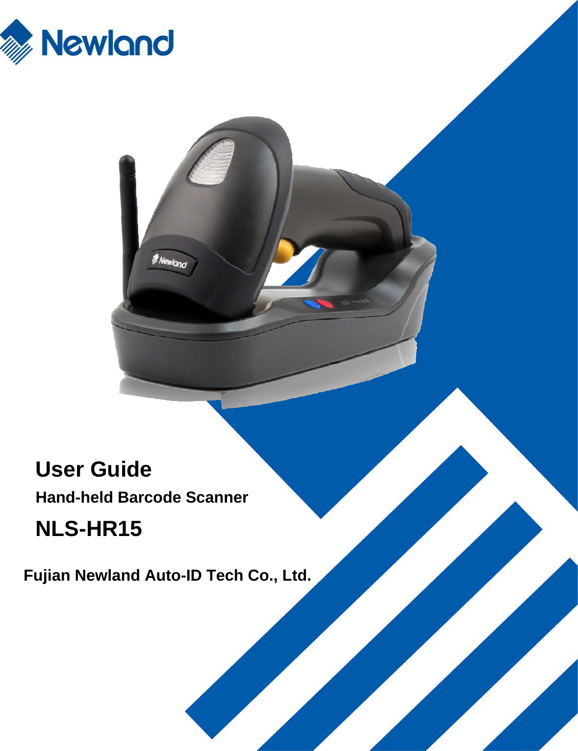
Fujian Newland Auto ID Tech NLS-HR15 Hand-held Barcode Scanner User Manual NLS HR15 x
Fujian Newland Auto-ID Tech Co., Ltd. Hand-held Barcode Scanner NLS HR15 x
UserManual.wiki
>
Fujian Newland Auto ID Tech
>
NLS HR15 User Manual
User Manual
Navigation menu
Upload a User Manual
Namespaces
Wiki Guide
HTML
PDF
Info
Views
User Manual
Discussion / Help
Navigation
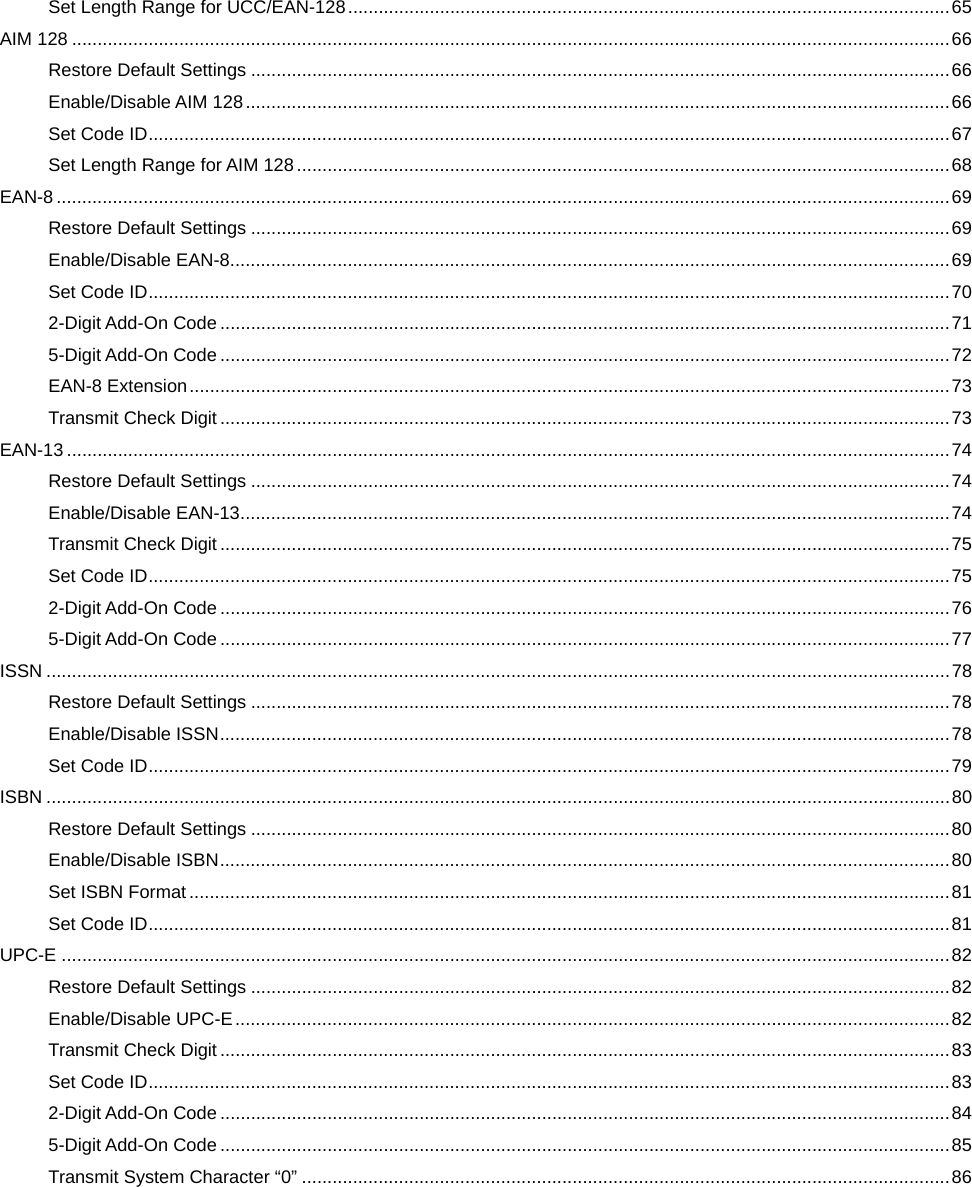
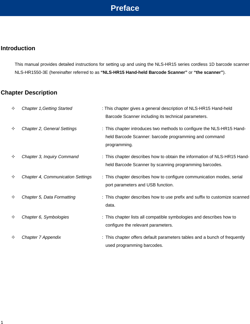
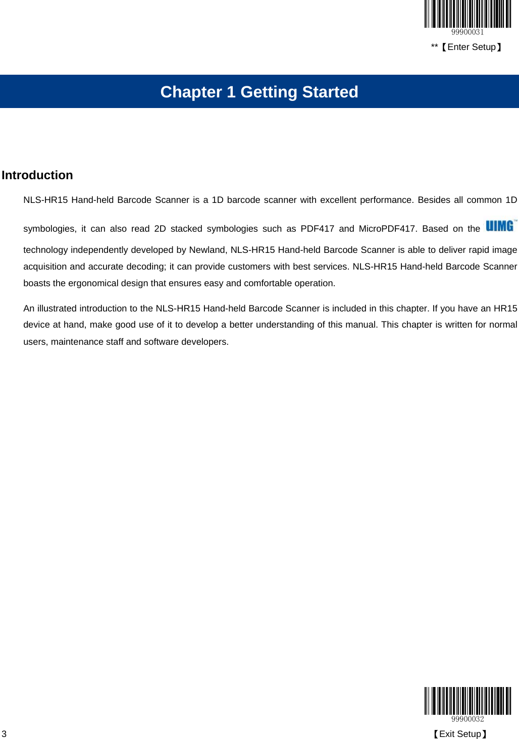
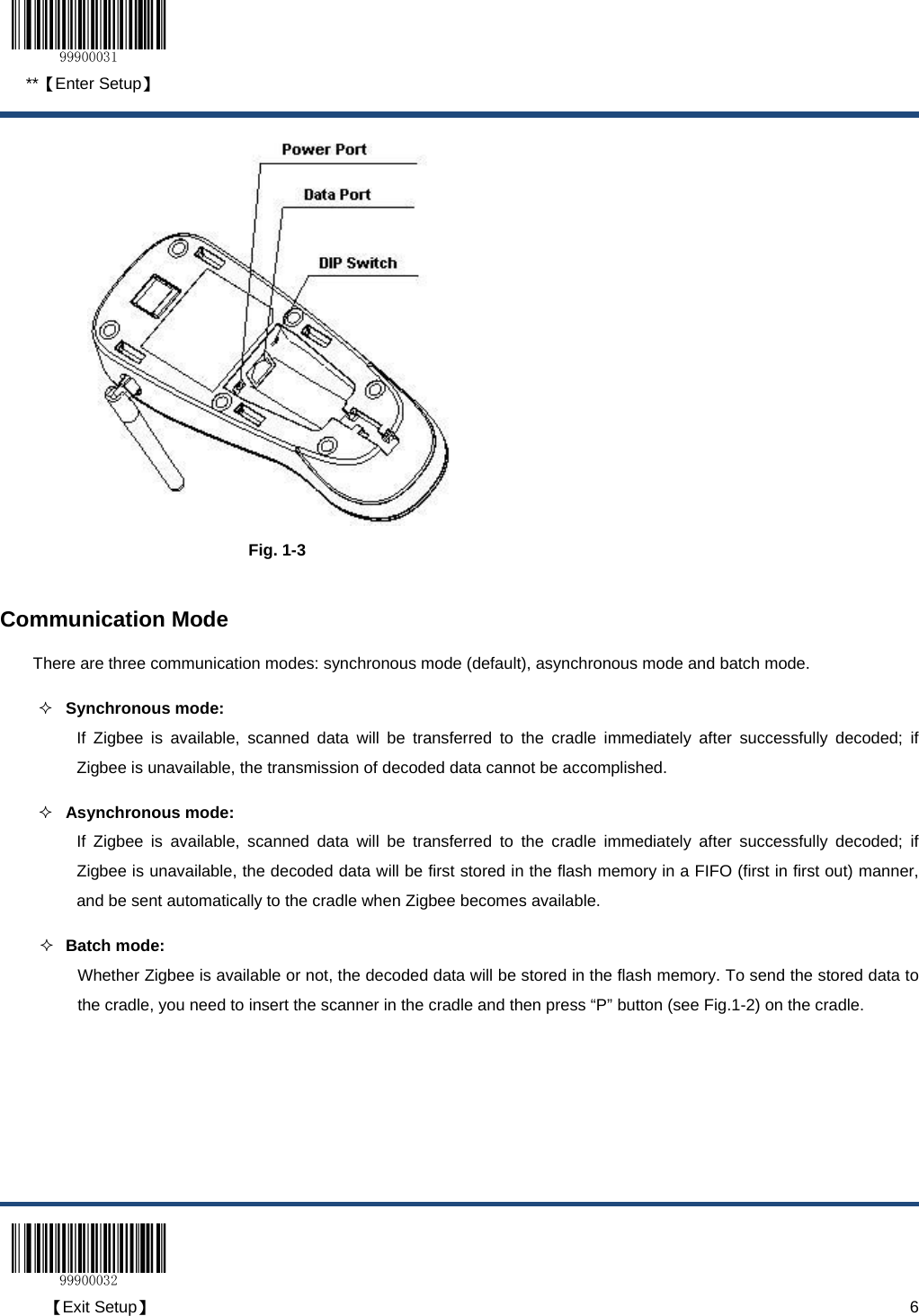
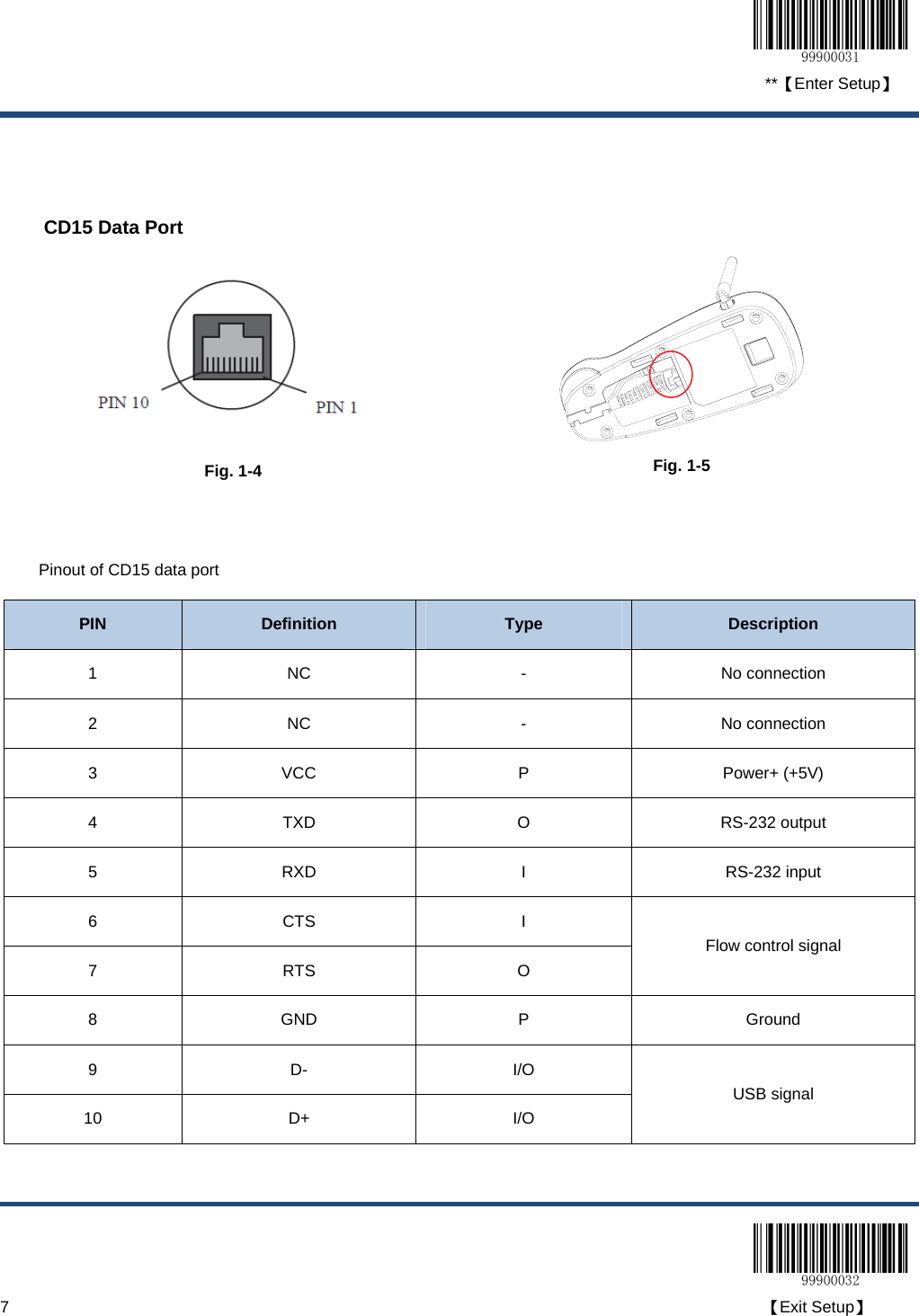
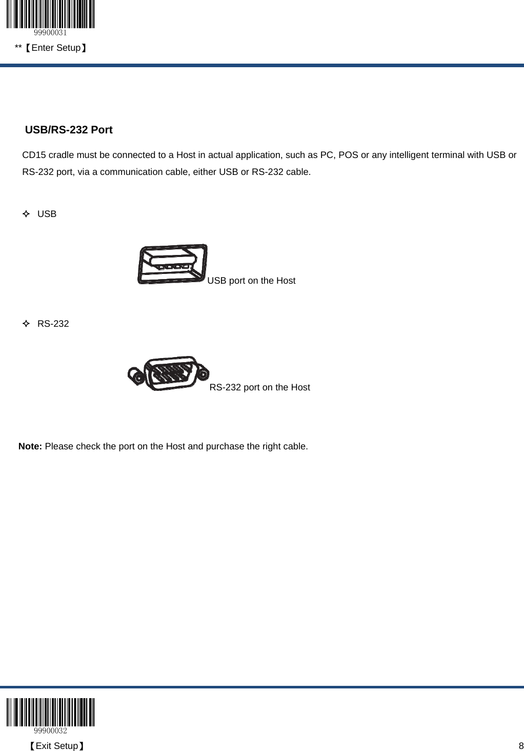
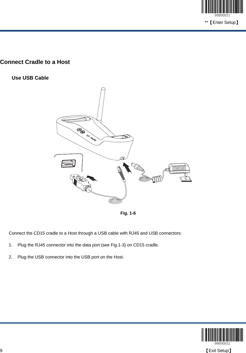
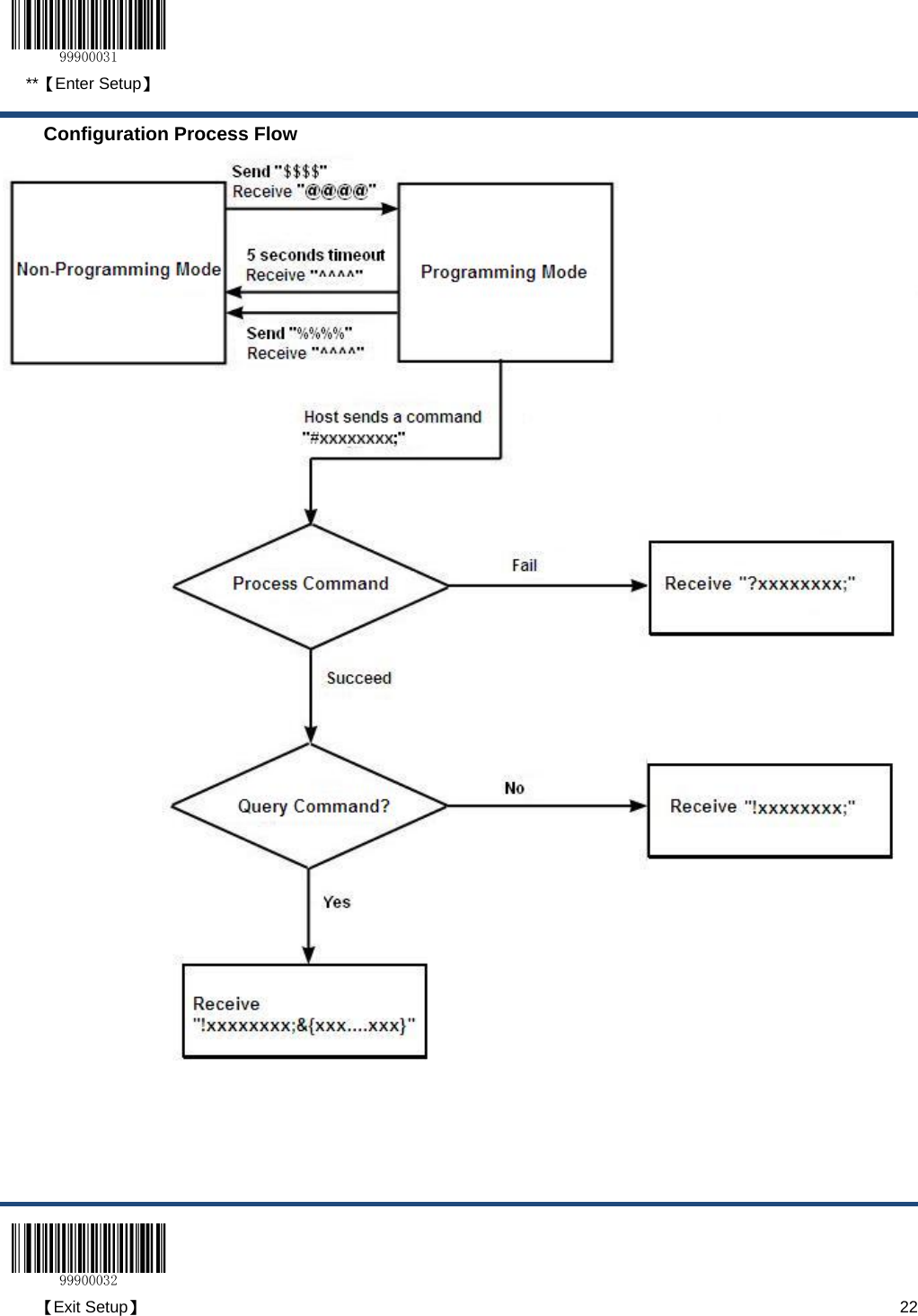


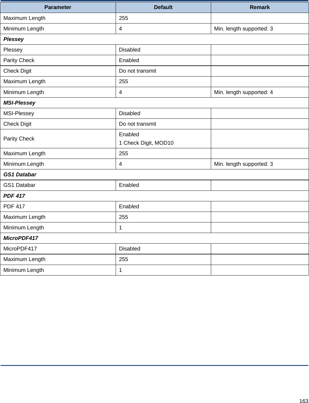
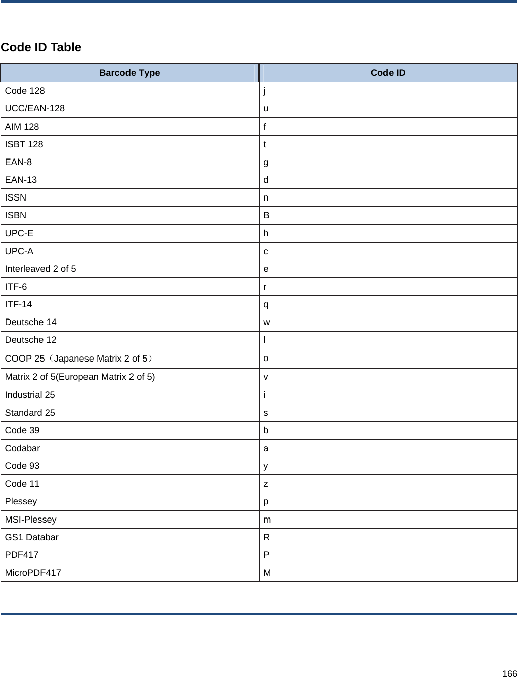
![164 AIM ID Table Barcode Type AIM ID Possible AIM ID Modifiers (m) Code 128 ]C0 UCC/EAN-128 ]C1 AIM 128 ]C2 EAN-8 ]E4 EAN-13 ]E0 EAN-13 with Add-On ]E3 ISSN ]X0 ISBN ]X0 UPC-E ]E0 UPC-E with Add-On ]E3 UPC-A ]E0 UPC-A with Add-On ]E3 Interleaved 2 of 5 ]Im 0,1,3 ITF-6 ]Im 1,3 ITF-14 ]Im 1,3 Deutsche 14 ]X0 Deutsche 12 ]X0 COOP 25(Japanese Matrix 2 of 5) ]X0 Matrix 2 of 5(European Matrix 2 of 5) ]X0 Industrial 25 ]S0 Standard 25 ]R0 Code 39 ]Am 0,1,3,4,5,7 Codabar ]Fm 0,2,4 Code 93 ]G0 Code 11 ]Hm 0,1,3 Plessey ]P0 MSI-Plessey ]Mm 0,1 GS1 Databar ]e0 PDF417 ]Lm 0,1,2 MicroPDF417 ]Lm 3,4,5 Note: “m” represents the AIM modifier character. Refer to ISO/IEC 15424:2008 Information technology – Automatic](https://usermanual.wiki/Fujian-Newland-Auto-ID-Tech/NLS-HR15/User-Guide-1935138-Page-174.png)