Fujian Newland Auto ID Tech NLS-HR32 Hand-held Barcode Scanner User Manual
Fujian Newland Auto-ID Tech Co., Ltd. Hand-held Barcode Scanner
UserManual
NLS-HR32
Hand-held Barcode Scanner
User Guide

Disclaimer
© 2013-2016 Fujian Newland Auto-ID Tech. Co., Ltd. All rights reserved.
Please read through the manual carefully before using the product and operate it according to the manual. It
is advised that you should keep this manual for future reference.
Do not disassemble the device or remove the seal label from the device, doing so will void the product
warranty provided by Fujian Newland Auto-ID Tech. Co., Ltd.
All pictures in this manual are for reference only and actual product may differ. Regarding to the product
modification and update, Fujian Newland Auto-ID Tech. Co., Ltd. reserves the right to make changes to any
software or hardware to improve reliability, function, or design at any time without notice. The information
contained herein is subject to change without prior notice.
The products depicted in this manual may include software copyrighted by Fujian Newland Auto-ID Tech. Co.,
Ltd or third party. The user, corporation or individual, shall not duplicate, in whole or in part, distribute, modify,
decompile, disassemble, decode, reverse engineer, rent, transfer or sublicense such software without prior
written consent from the copyright holders.
This manual is copyrighted. No part of this publication may be reproduced, distributed or used in any form
without written permission from Newland.
Fujian Newland Auto-ID Tech. Co., Ltd. reserves the right to make final interpretation of the statement above.
Fujian Newland Auto-ID Tech. Co., Ltd.
3F, Building A, No.1, Rujiang West Rd., Mawei, Fuzhou, Fujian, China 350015
http://www.nlscan.com

Revision History
Version
Description
Date
V1.0.0
Initial release.
June 26, 2013
V1.0.1
Updates:
1. Added the Germany keyboard, Emulate Alt+Keypad, Function
Key Mapping and Emulate Numeric Keypad features in Chapter
4.
2. Added ASCII Function Key Mapping Table in Appendix.
April 16, 2014
V1.0.2
Modified the default length range of Code 39, PDF417, QR Code
and Data Matrix.
March 27, 2015
V1.0.3
Updates:
1. Deleted the EzSet123 Programming section in Chapter 2.
2. Added “Note: Maximum barcode length supported by the scanner
is 1024 bytes.” in the Introduction section of Chapter 5.
May 12, 2015
V1.0.4
Added the following keyboard types: Belgium, Russia, Sweden and
Portugal in Chapter 4.
December 2, 2015
V1.0.5
Added the Examine KBW Connection feature in Chapter 4.
April 29, 2016
V1.0.6
Updates:
1. Added the Pair Cradle with Zigbee Router section and the
Timeout between Decodes (Same Barcode) for the Manual
mode in Chapter 2.
2. Added two options of 60ms and 80ms for inter-keystroke delay
and the USB HID-POS feature in Chapter 4.
Note: You must have firmware version V1.2.11 or higher to use the
new features above.
June 2, 2016

Table of Contents
Revision History ........................................................................................................................................... - 3 -
Preface ............................................................................................................................................................... 1
Introduction ............................................................................................................................................ 1
Chapter Description ............................................................................................................................... 1
Explanation of Icons .............................................................................................................................. 2
Chapter 1 Getting Started ................................................................................................................................ 3
Introduction ............................................................................................................................................ 3
Features of the HR32 ............................................................................................................................ 3
Unpacking .............................................................................................................................................. 3
Scanner .................................................................................................................................................. 4
CD32 Cradle .......................................................................................................................................... 5
Communication Mode ............................................................................................................................ 6
CD32 Data Port ............................................................................................................................... 6
USB/RS-232 Port ............................................................................................................................ 7
Connecting Cradle to a Host ................................................................................................................. 7
Use USB Cable................................................................................................................................ 8
Use RS-232 Cable ........................................................................................................................... 9
Power On, Sleep, Power Off, Reboot .................................................................................................. 10
Maintenance ........................................................................................................................................ 10
Dimensions of Scanner ........................................................................................................................ 11
Side View ....................................................................................................................................... 11
Front View ...................................................................................................................................... 11
Top View ........................................................................................................................................ 11
Dimensions of CD32 Cradle ................................................................................................................ 12
Scanning Instructions .......................................................................................................................... 13
Chapter 2 System Settings ............................................................................................................................ 15
Introduction .......................................................................................................................................... 15
Barcode Programming ................................................................................................................... 15
Command Programming ............................................................................................................... 15
Programming Barcode/Command/Function ........................................................................................ 16
Use of Programming Barcodes ........................................................................................................... 17
Factory Defaults ................................................................................................................................... 18

Pairing Settings .................................................................................................................................... 19
Pair Scanner with Cradle ............................................................................................................... 19
Pair Cradle with Zigbee Router ..................................................................................................... 19
Search Paired Scanners................................................................................................................ 19
Operating Mode Options ...................................................................................................................... 20
Power-Off Timeout ............................................................................................................................... 21
Illumination ........................................................................................................................................... 22
Aiming .................................................................................................................................................. 23
Beep ..................................................................................................................................................... 24
Good Read Beep ........................................................................................................................... 24
Good Read Beep Type .................................................................................................................. 24
Good Read Beep Volume .............................................................................................................. 25
Startup Beep .................................................................................................................................. 25
Transmit NGR Message ...................................................................................................................... 26
Edit NGR Message ........................................................................................................................ 26
Scan Mode ........................................................................................................................................... 27
Manual Mode ................................................................................................................................. 27
Decode Session Timeout ....................................................................................................... 27
Timeout between Decodes (Same Barcode) ......................................................................... 28
Sense Mode ................................................................................................................................... 29
Decode Session Timeout ....................................................................................................... 29
Image Stabilization Timeout ................................................................................................... 30
Continue after Good Read ..................................................................................................... 30
Timeout between Decodes (Same Barcode) ......................................................................... 31
Sensitivity ............................................................................................................................... 32
Continuous Mode .......................................................................................................................... 33
Decode Session Timeout ....................................................................................................... 33
Timeout between Decodes..................................................................................................... 34
Chapter 3 Inquiry Command ......................................................................................................................... 35
Introduction .......................................................................................................................................... 35
Obtain Scanner Information ................................................................................................................. 35
Obtain Cradle Information .................................................................................................................... 35
Obtain FLASH Information ................................................................................................................... 36
Chapter 4 Communication Settings ............................................................................................................. 37
Introduction .......................................................................................................................................... 37
Wireless Communication ..................................................................................................................... 37
RS-232 Interface .................................................................................................................................. 38

Baud Rate ...................................................................................................................................... 38
Parity Check .................................................................................................................................. 39
Stop Bit .......................................................................................................................................... 39
Hareware Flow Control .................................................................................................................. 40
Data Bit .......................................................................................................................................... 40
USB Interface ....................................................................................................................................... 41
USB HID-KBW ............................................................................................................................... 41
Examine KBW Connection ..................................................................................................... 41
USB Country Keyboard Types ............................................................................................... 42
Inter-Keystroke Delay ............................................................................................................. 44
Convert Case ......................................................................................................................... 45
Emulate ALT+Keypad ............................................................................................................. 46
Function Key Mapping ........................................................................................................... 47
Emulate Numeric Keypad ...................................................................................................... 48
USB COM Port Emulation ............................................................................................................. 49
USB HID-POS ............................................................................................................................... 49
Introduction ............................................................................................................................. 49
Access the Scanner with Your Program................................................................................. 49
Acquire Scanned Data ........................................................................................................... 50
Send Data to the Scanner ...................................................................................................... 50
VID/PID ................................................................................................................................... 50
Chapter 5 Symbologies ................................................................................................................................. 51
Introduction .......................................................................................................................................... 51
General Settings .................................................................................................................................. 51
Disable All Symbologies ................................................................................................................ 51
Enable All Symbologies ................................................................................................................. 51
Enable 1D Symbologies ................................................................................................................ 52
Disable 1D Symbologies ............................................................................................................... 52
Enable 2D Symbologies ................................................................................................................ 52
Disable 2D Symbologies ............................................................................................................... 52
Video Reverse ............................................................................................................................... 53
Code 128 ............................................................................................................................................. 54
Restore Factory Defaults ............................................................................................................... 54
Enable/Disable Code 128 .............................................................................................................. 54
Set Length Range for Code 128 .................................................................................................... 55
EAN-8 ................................................................................................................................................... 56
Restore Factory Defaults ............................................................................................................... 56

Enable/Disable EAN-8 ................................................................................................................... 56
Transmit Check Digit ..................................................................................................................... 56
Add-On Code ................................................................................................................................. 57
Add-On Code Required ................................................................................................................. 58
EAN-8 Extension ........................................................................................................................... 58
EAN-13 ................................................................................................................................................. 59
Restore Factory Defaults ............................................................................................................... 59
Enable/Disable EAN-13 ................................................................................................................. 59
Transmit Check Digit ..................................................................................................................... 59
Add-On Code ................................................................................................................................. 60
Add-On Code Required ................................................................................................................. 61
UPC-E .................................................................................................................................................. 62
Restore Factory Defaults ............................................................................................................... 62
Enable/Disable UPC-E .................................................................................................................. 62
Transmit Check Digit ..................................................................................................................... 62
Add-On Code ................................................................................................................................. 63
Add-On Code Required ................................................................................................................. 64
Transmit System Character “0” ..................................................................................................... 64
UPC-E Extension ........................................................................................................................... 65
UPC-A .................................................................................................................................................. 66
Restore Factory Defaults ............................................................................................................... 66
Enable/Disable UPC-A .................................................................................................................. 66
Transmit Check Digit ..................................................................................................................... 66
Add-On Code ................................................................................................................................. 67
Add-On Code Required ................................................................................................................. 68
Transmit Preamble Character “0” .................................................................................................. 68
Interleaved 2 of 5 ................................................................................................................................. 69
Restore Factory Defaults ............................................................................................................... 69
Enable/Disable Interleaved 2 of 5 ................................................................................................. 69
Set Length Range for Interleaved 2 of 5 ....................................................................................... 70
Check Digit Verification .................................................................................................................. 71
ITF-14 ................................................................................................................................................... 72
ITF-6 ..................................................................................................................................................... 73
Matrix 2 of 5 ......................................................................................................................................... 74
Restore Factory Defaults ............................................................................................................... 74
Enable/Disable Matrix 2 of 5 ......................................................................................................... 74
Set Length Range for Matrix 2 of 5 ............................................................................................... 75
Check Digit Verification .................................................................................................................. 76

Code 39................................................................................................................................................ 77
Restore Factory Defaults ............................................................................................................... 77
Enable/Disable Code 39 ................................................................................................................ 77
Transmit Start/Stop Character ....................................................................................................... 77
Set Length Range for Code 39 ...................................................................................................... 78
Check Digit Verification .................................................................................................................. 79
Enable/Disable Code 39 Full ASCII .............................................................................................. 80
Codabar ............................................................................................................................................... 81
Restore Factory Defaults ............................................................................................................... 81
Enable/Disable Codabar................................................................................................................ 81
Set Length Range for Codabar ..................................................................................................... 82
Check Digit Verification .................................................................................................................. 83
Start/Stop Character ...................................................................................................................... 84
Code 93................................................................................................................................................ 85
Restore Factory Defaults ............................................................................................................... 85
Enable/Disable Code 93 ................................................................................................................ 85
Set Length Range for Code 93 ...................................................................................................... 86
Check Digit Verification .................................................................................................................. 87
UCC/EAN-128 ...................................................................................................................................... 88
Restore Factory Defaults ............................................................................................................... 88
Enable/Disable UCC/EAN-128 ...................................................................................................... 88
Set Length Range for UCC/EAN-128 ............................................................................................ 89
GS1 Databar ........................................................................................................................................ 90
Restore Factory Defaults ............................................................................................................... 90
Enable/Disable GS1 Databar ........................................................................................................ 90
Transmit Application Identifier “01” ................................................................................................ 90
Code 11 ................................................................................................................................................ 91
Restore Factory Defaults ............................................................................................................... 91
Enable/Disable Code 11 ................................................................................................................ 91
Set Length Range for Code 11 ...................................................................................................... 92
Check Digit Verification .................................................................................................................. 93
ISBN ..................................................................................................................................................... 94
Restore Factory Defaults ............................................................................................................... 94
Enable/Disable ISBN ..................................................................................................................... 94
Set ISBN Format............................................................................................................................ 94
Add-On Code ................................................................................................................................. 95
Add-On Code Required ................................................................................................................. 96
ISSN ..................................................................................................................................................... 97

Restore Factory Defaults ............................................................................................................... 97
Enable/Disable ISSN ..................................................................................................................... 97
Add-On Code ................................................................................................................................. 98
Add-On Code Required ................................................................................................................. 99
AIM-128.............................................................................................................................................. 100
Restore Factory Defaults ............................................................................................................. 100
Enable/Disable AIM-128 .............................................................................................................. 100
Set Length Range for AIM-128 .................................................................................................... 101
Industrial 25 ....................................................................................................................................... 102
Restore Factory Defaults ............................................................................................................. 102
Enable/Disable Industrial 25 ........................................................................................................ 102
Set Length Range for Industrial 25.............................................................................................. 103
Check Digit Verification ................................................................................................................ 104
Standard 25 ........................................................................................................................................ 105
Restore Factory Defaults ............................................................................................................. 105
Enable/Disable Standard 25 ........................................................................................................ 105
Set Length Range for Standard 25 .............................................................................................. 106
Check Digit Verification ................................................................................................................ 107
Plessey ............................................................................................................................................... 108
Restore Factory Defaults ............................................................................................................. 108
Enable/Disable Plessey ............................................................................................................... 108
Set Length Range for Plessey ..................................................................................................... 109
Check Digit Verification ................................................................................................................ 110
MSI-Plessey ........................................................................................................................................ 111
Restore Factory Defaults .............................................................................................................. 111
Enable/Disable MSI-Plessey ........................................................................................................ 111
Set Length Range for MSI-Plessey ............................................................................................. 112
Check Digit Verification ................................................................................................................ 113
PDF417 .............................................................................................................................................. 114
Restore Factory Defaults ............................................................................................................. 114
Enable/Disable PDF417 .............................................................................................................. 114
Set Length Range for PDF417 .................................................................................................... 115
QR Code ............................................................................................................................................ 116
Restore Factory Defaults ............................................................................................................. 116
Enable/Disable QR Code ............................................................................................................ 116
Set Length Range for QR Code .................................................................................................. 117
Micro QR ...................................................................................................................................... 118
Data Matrix ......................................................................................................................................... 119

Restore Factory Defaults ............................................................................................................. 119
Enable/Disable Data Matrix ......................................................................................................... 119
Set Length Range for Data Matrix ............................................................................................... 120
Rectangular Barcode ................................................................................................................... 121
Mirror Image ................................................................................................................................ 121
Chapter 6 Prefix & Suffix ............................................................................................................................. 122
Introduction ........................................................................................................................................ 122
General Settings ................................................................................................................................ 123
Enable/Disable All Prefix/Suffix ................................................................................................... 123
Prefix Sequences ........................................................................................................................ 123
Custom Prefix .................................................................................................................................... 124
Enable/Disable Custom Prefix ..................................................................................................... 124
Set Custom Prefix ........................................................................................................................ 124
AIM ID Prefix ...................................................................................................................................... 125
Code ID Prefix .................................................................................................................................... 125
Restore All Default Code IDs ....................................................................................................... 126
Modify Code ID ............................................................................................................................ 126
Custom Suffix ..................................................................................................................................... 130
Enable/Disable Custom Suffix ..................................................................................................... 130
Set Custom Suffix ........................................................................................................................ 130
Terminating Character Suffix ............................................................................................................. 131
Enable/Disable Terminating Character Suffix .............................................................................. 131
Set Terminating Character Suffix ................................................................................................. 131
Chapter 7 Ambient Illumination .................................................................................................................. 133
Appendix ....................................................................................................................................................... 134
Digit Barcodes .................................................................................................................................... 134
Save/Cancel Barcodes ...................................................................................................................... 137
Factory Defaults Table ....................................................................................................................... 138
AIM ID Table....................................................................................................................................... 145
Code ID Table .................................................................................................................................... 148
ASCII Table ........................................................................................................................................ 149
ASCII Function Key Mapping Table ................................................................................................... 153

1
Preface
Introduction
This manual provides detailed instructions for setting up and using the NLS-HR3260 Series cordless 2D
barcode scanner (hereinafter referred to as “HR32 cordless scanner” or “the scanner”).
Chapter Description
Chapter 1, Getting Started
Gives a general description of HR32 cordless scanner.
Chapter 2, System Settings
Introduces three configuration methods and describes how
to configure general parameters of HR32 cordless
scanner.
Chapter 3, Inquiry Command
Describes how to obtain the information of HR32 cordless
scanner by scanning programming barcodes.
Chapter 4, Communication Settings
Describes how to configure communication mode, serial
port parameters and USB function.
Chapter 5, Symbologies
Lists all compatible symbologies and describes how to
configure the relevant parameters.
Chapter 6, Prefix & Suffix
Describes how to use prefix and suffix to customize
scanned data.
Chapter 7, Ambient Illumination
Describes how to configure the scanner to adapt it to
ambient light of different intensity.
Appendix
Provides factory defaults table and a bunch of frequently
used programming barcodes.

2
Explanation of Icons
This icon indicates something relevant to this manual.
This icon indicates this information requires extra attention from the reader.
This icon indicates handy tips that can help you use or configure the scanner with ease.
This icon indicates practical examples that can help you to acquaint yourself with operations.

3
Chapter 1 Getting Started
Introduction
The HR32 cordless scanner reads a 1D or 2D barcode by capturing its image. Adopting the advanced
technology independently developed by Newland Auto-ID Tech, it provides users with three scan
modes, including Manual Mode, Sense Mode and Continuous Mode, tailored to different scanning needs.
An illustrated introduction to the HR32 cordless scanner is included in this chapter. If you have an HR32
cordless scanner at hand, make good use of it to develop a better understanding of this manual. This
chapter is written for normal users, maintenance staff and software developers.
Features of the HR32
Comprehensive data capture: most 1D and 2D barcodes.
Fast and accurate decoding capability: integrates high-performance processor and barcode decoder
board.
Easy to configure and update.
Unpacking
Open the package and take out HR32 cordless scanner and its accessories. Check to make sure
everything on the packing list is present and intact. If any contents are damaged or missing, please keep
the original package and contact your dealer immediately for after-sale service.
Note: CD32, the cradle for HR32 cordless scanner is individually wrapped.
4
Scanner
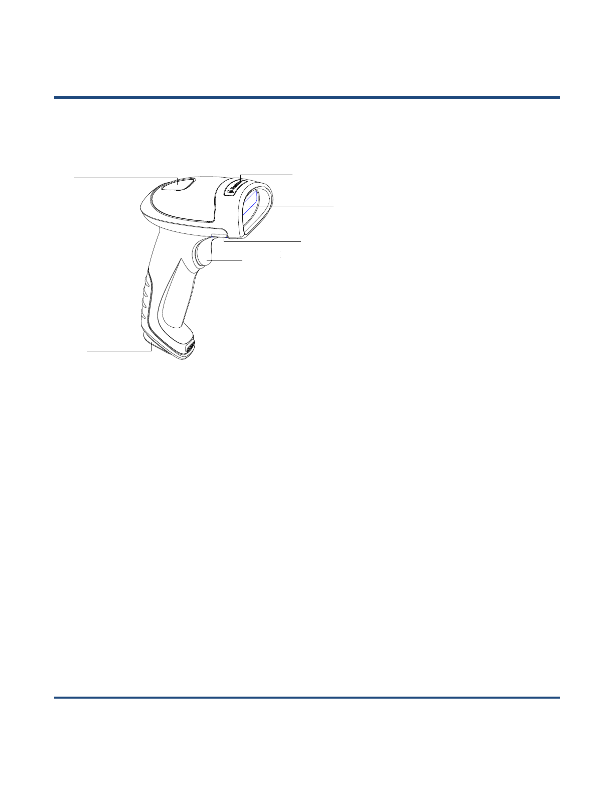
Fig. 1-1
Decode/Transmission LED:
Green: Barcode decoded successfully.
Battery is fully charged.
Blue: Zigbee is available.
Red: Data transmission failed.
Device is charging.
Purple: Firmware update is in progress.
There is data in FLASH memory.
Decode/Transmission LED
Logo
Scan Window
Label
Trigger
Reset Button
5
CD32 Cradle
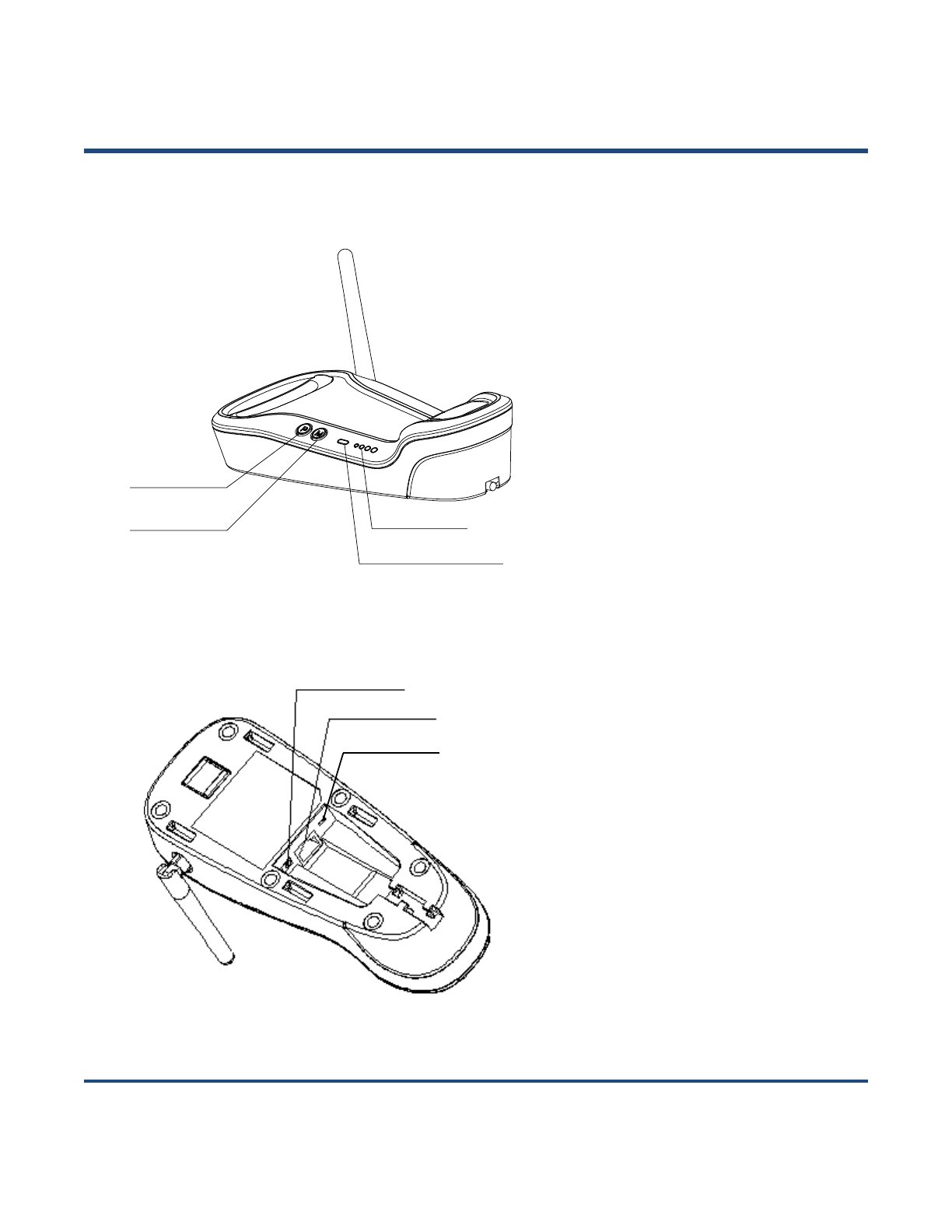
Fig. 1-2
Buttons:
P: Batch Transmission
M: Pair/Search
LEDs:
Zigbee LED (blue):
Zigbee is available.
Battery LEDs (green):
Indicates battery level (four levels)
Fig. 1-3
Batch Transmission
Pair/Search
Battery LEDs
Zigbee LED
Power Port
Data Port
DIP Switch
6
Communication Mode
Communication modes: synchronous mode (default), asynchronous mode and batch mode.
Synchronous Mode: If Zigbee is available, scanned data will be transferred to the cradle
immediately after a good read; if Zigbee is unavailable, the transmission of decoded data cannot be
accomplished.
Asynchronous Mode: If Zigbee is available, scanned data will be transferred to the cradle
immediately after a good read; if Zigbee is unavailable, the decoded data will be first stored in the
flash memory in a FIFO (first in first out) manner, and be sent automatically to the cradle when
Zigbee becomes available.
Batch Mode: The decoded data will be stored in the flash memory no matter whether Zigbee is
available or not. To send the stored data to the cradle, you need to insert the scanner in the cradle
and then press “P” button on the cradle.
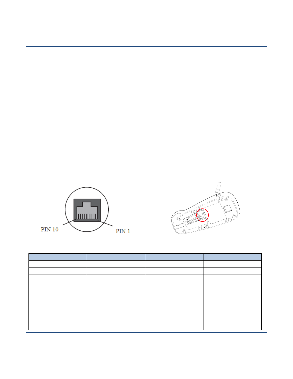
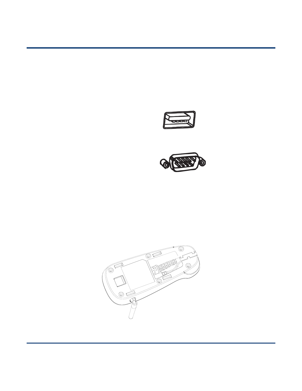
CD32 Data Port
Fig. 1-4
PIN
Signal
Type
Function
1
NC
-
No connection
2
NC
-
No connection
3
VCC
P
Power+ (+5V)
4
TXD
O
RS-232 output
5
RXD
I
RS-232 input
6
CTS
I
Flow control signal
7
RTS
O
8
GND
P
Ground
9
D-
I/O
USB signal
10
D+
I/O
7
USB/RS-232 Port
CD32 cradle must be connected to a Host in actual application, such as PC, POS or any intelligent
terminal with USB or RS-232 port, via a communication cable, either USB or RS-232 cable.
USB
USB port on the Host
RS-232
RS-232 port on the Host
Note: Please check the port on the Host and purchase the right cable.
Connecting Cradle to a Host
Fig. 1-5
8
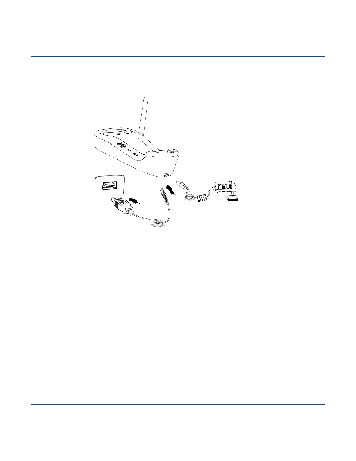
Use USB Cable
Fig. 1-6
Connect the CD32 cradle to a Host through a USB cable with RJ45 and USB connectors:
1. Plug the RJ45 connector into the data port (see Fig.1-3) on the cradle.
2. Plug the USB connector into the USB port on the Host.
3. Plug the supplied power adapter into the power port (see Fig.1-3) on the cradle.
9
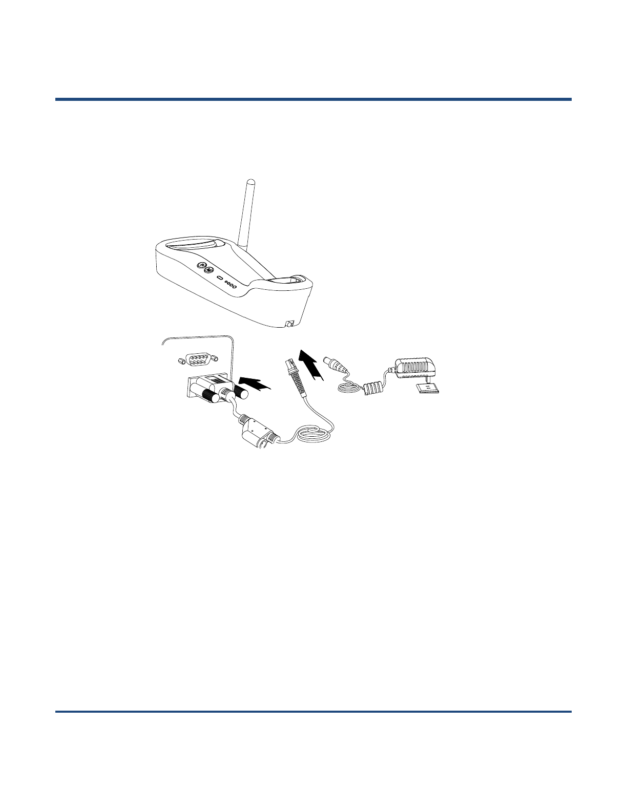
Use RS-232 Cable
Fig. 1-7
Connect the CD32 cradle to a Host through an RS-232 cable with RJ45 and RS-232 connectors:
1. Plug the RJ45 connector into the data port (see Fig.1-3) on the cradle.
2. Plug the RS-232 connector into the RS-232 port on the Host.
3. Plug the supplied power adapter into the power port (see Fig.1-3) on the cradle.

10
Power On, Sleep, Power Off, Reboot
Powering on the scanner
Hold down the trigger on the scanner for 1 second or longer.
Entering the sleep mode
If no operation is performed on the scanner for 5 seconds, it will automatically enter the sleep mode.
(Applicable to the Manual mode only)
Powering off the scanner
Scan the Power Off barcode. (See the Operating Mode Options in Chapter 2)
Note: The scanner that has remained in sleep mode for a specific time period (default: 5 minutes,
programmable) will be automatically turned off. (To change the time period, see the Power-Off Timeout
in Chapter 2).
Rebooting the scanner
If the scanner stops responding to input or runs abnormally, press the Reset button on the scanner to
reboot it.
Maintenance
1. The scan window should be kept clean.
2. Do not scratch the scan window.
3. Use soft brush to remove the stain from the scan window.
4. Use the soft cloth to clean the window, such as eyeglass cleaning cloth.
5. Do not spray any liquid on the scan window.
6. Only use water to clean other parts of the device.
The warranty DOES NOT cover damages caused by inappropriate care and
maintenance.
11
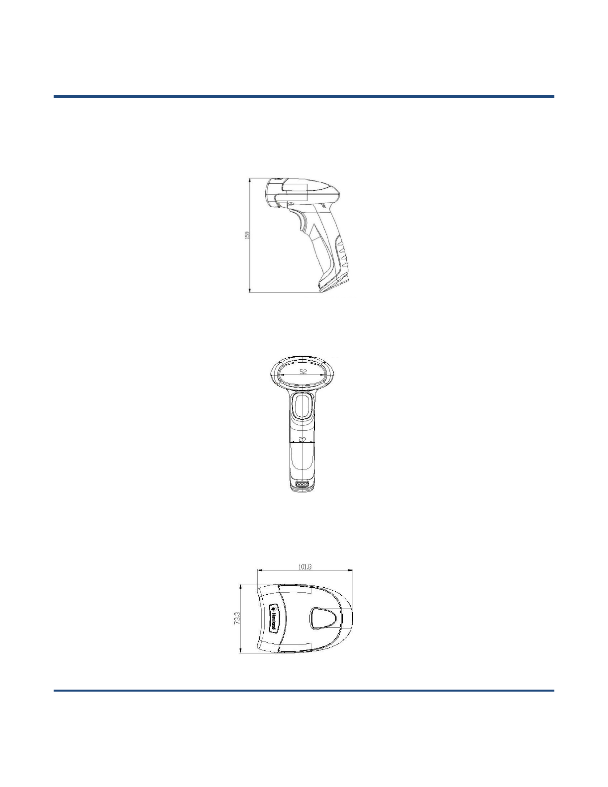
Dimensions of Scanner
Side View
Fig. 1-8
Front View
Fig. 1-9
Top View
Fig. 1-10
unit: mm
unit: mm
unit: mm
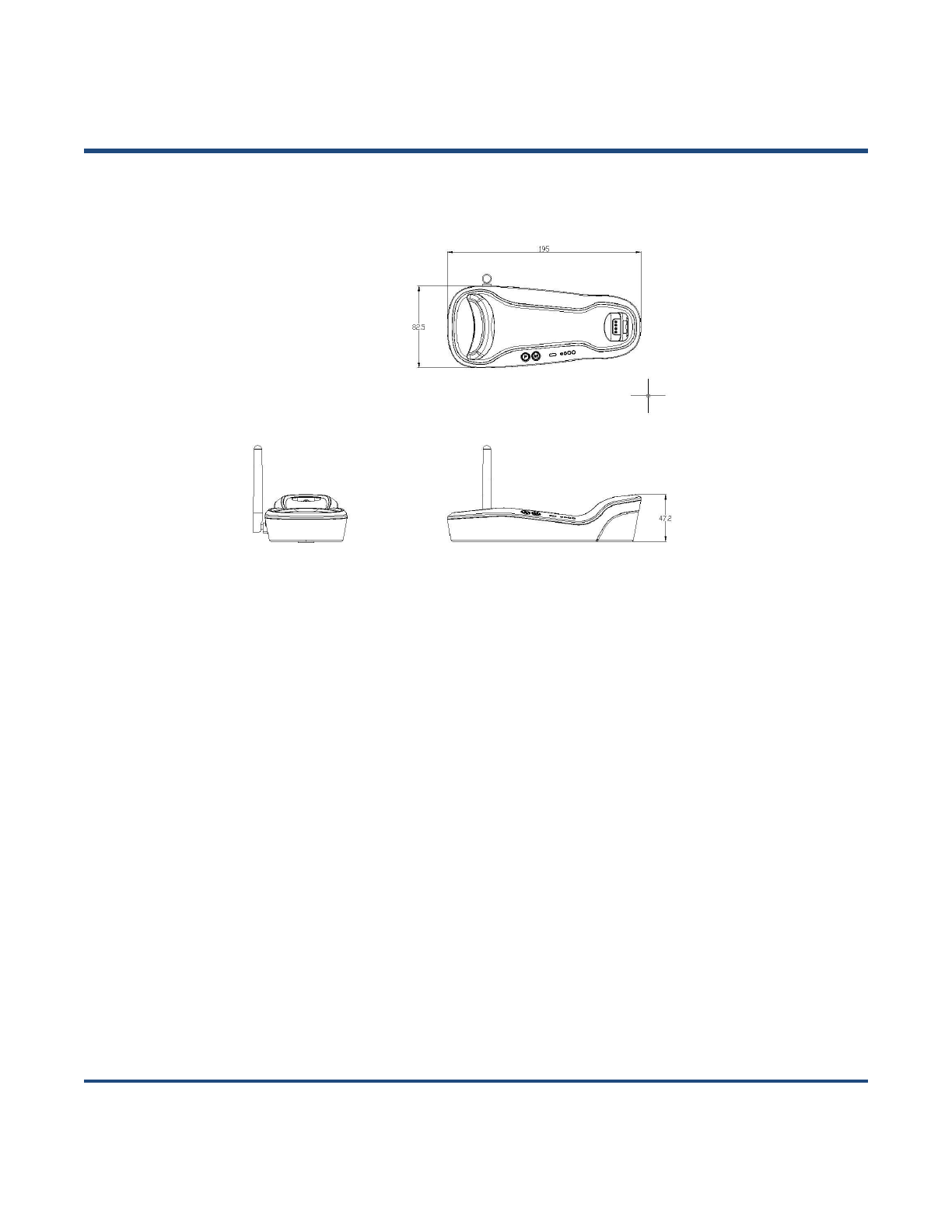
12
Dimensions of CD32 Cradle
Fig. 1-11
13
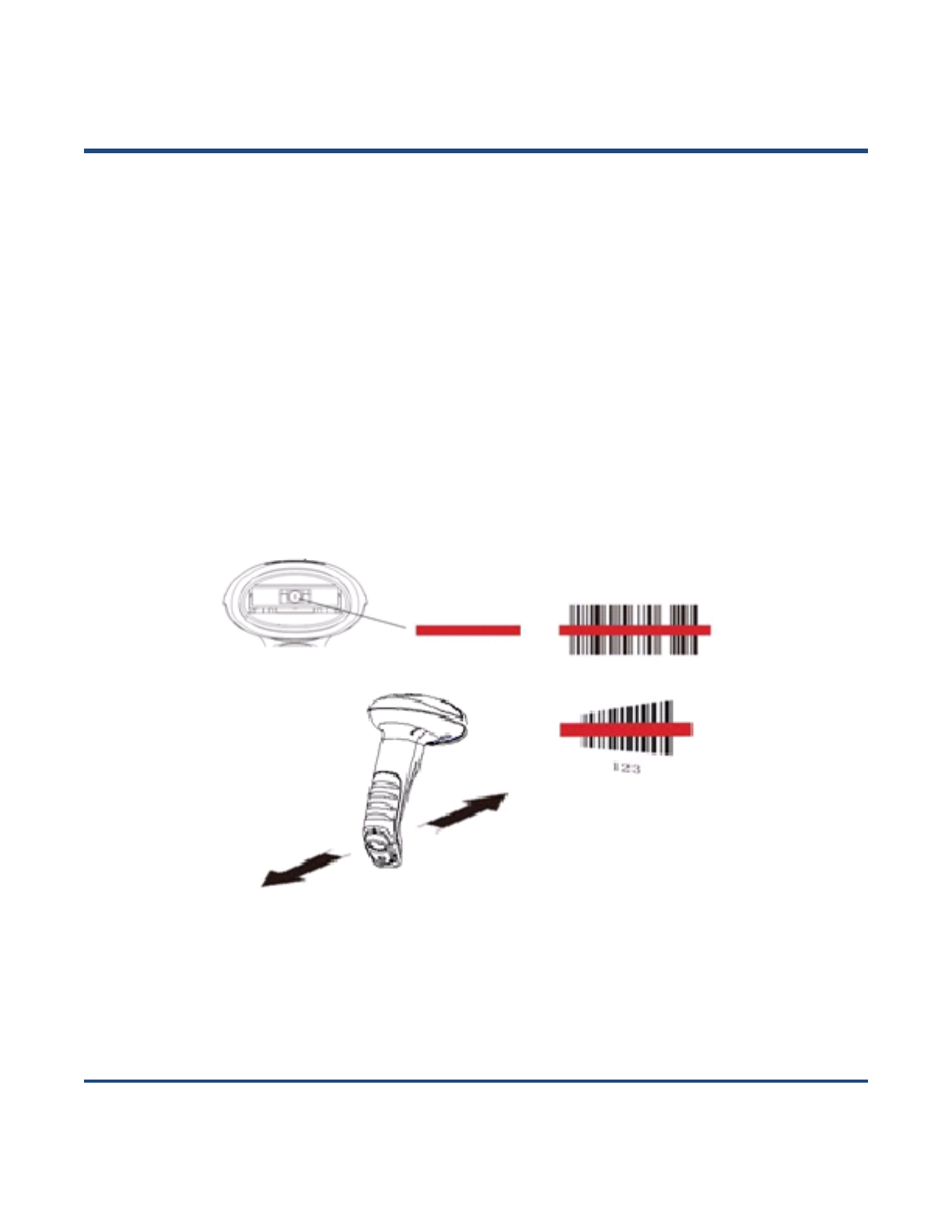
Scanning Instructions
When the scanner is in the Manual scan mode, you can follow the steps below to scan a barcode:
1. Press and hold the trigger. Then the scanner will project a red aiming beam.
2. Aim the red beam across the center of barcode, as shown in Fig.1-12.
3. Release the trigger when the red beam goes off. If the barcode is decoded successfully, the scanner
will beep and the decoded data will be sent to the Host.
Note: For the same batch of barcodes, the scanner will keep a very high success ratio in certain distance
which can be regarded as the optimal scanning distance.
Fig. 1-12
14
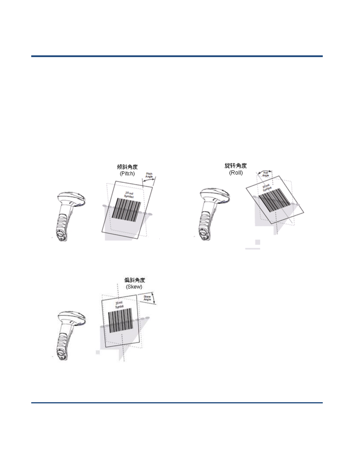
Scan Angle
The scanner is designed to function within a certain range of scan angles. Any unreasonable deviation
may cause decoding failure.
Scan angles of the scanner:
Pitch: ±55°, 0° Roll and 0° Skew (Fig. 1-13)
Roll: 360°, 0 Pitch and 0° Skew (Fig. 1-14)
Skew: ±55°, 0° Roll and 0° Pitch (Fig. 1-15)
Fig. 1-13
Fig. 1-14
Fig. 1-15

【Enter Setup】
15 **【Exit Setup】
Chapter 2 System Settings
Introduction
There are two ways to configure the scanner: barcode programming and command programming.
Barcode Programming
The scanner can be configured through scanning programming barcodes. In the following sections, we
will explain the available options and features and provide the barcodes to program them.
This programming method is most straightforward. However, it requires manually scanning barcodes. As
a result, errors are more likely to occur.
Command Programming
The scanner can also be configured by command strings sent from the Host. In the following sections, the
commands will be provided along with programming barcodes.
Users can also design an application to send those command strings to their scanners.
Note: All settings except temporary ones are stored in non-volatile memory of the scanner and
will not be lost by removing power from the scanner.
【Enter Setup】
**【Exit Setup】 16
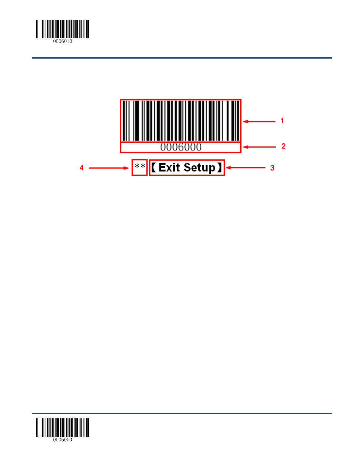
Programming Barcode/Command/Function
The figure above is an example that shows you the programming barcode and command for the Exit
Setup function:
1. The Exit Setup barcode
2. The Exit Setup command
3. The function/feature that can be enabled by using the programming barcode or command listed
above.
4. ** indicates factory default setting.

【Enter Setup】
17 **【Exit Setup】
Use of Programming Barcodes
Scanning the Enter Setup barcode can enable the scanner to enter the setup mode. Then you can scan
a number of programming barcodes to configure your scanner. To exit the setup mode, scan the Exit
Setup barcode.
After scanning the Exit Setup barcode, only some special programming barcodes, such as the Enter
Setup barcode, can be read.
**【Exit Setup】
【Enter Setup】

【Enter Setup】
**【Exit Setup】 18
Factory Defaults
Scanning the Reset Scanner barcode/the Reset Cradle barcode can restore the scanner/cradle to the
factory default settings.
You may need to reset your scanner/cradle when:
1. scanner/cradle is not properly configured so that the scanner fails to decode barcodes or to
communicate with cradle;
2. you forget previous configuration and want to avoid its impact;
3. functions that are rarely used have been enabled for the time being.
【Reset Scanner】
【Reset Cradle】

【Enter Setup】
19 **【Exit Setup】
Pairing Settings
Pair Scanner with Cradle
A cradle with its DIP switch (see Fig. 1-3) in the “C” position works as a normal cradle.
The scanner and cradle must be paired for communication to occur. A cradle can be paired with multiple
scanners.
You need to perform this operation manually: After the scanner and cradle are powered on, insert the
scanner in the cradle and then press the “M” button on the cradle. The scanner beeps on a successful
pairing.
Pair Cradle with Zigbee Router
A cradle with its DIP switch (see Fig. 1-3) in the “R” position functions as a Zigbee router. You can extend
communication distance of the cradle by pairing multiple Zigbee routers with it.
To pair a cradle (DIP switch in the “C” position) with a Zigbee router (DIP switch in the “R” position):
a. Pair a scanner with the cradle by following the instructions above.
b. Insert the paired scanner in the Zigbee router and then press the “M” button on the router.
The scanner beeps on a successful pairing.
Search Paired Scanners
When scanner(s) and cradle are powered on, press the “M” button on the cradle and the paired scanner(s)
will beep.

【Enter Setup】
**【Exit Setup】 20
Operating Mode Options
【Power Off】
【Reboot Scanner】
【Reboot Scanner】
【Enter Setup】
21 **【Exit Setup】
Power-Off Timeout
Power-off timeout specifies the amount of time the scanner remains in sleep mode before it powers off
automatically. Scan the barcode below to set this parameter.
**【5 Minutes】
【10 Minutes】
【20 Minutes】
【30 Minutes】
【60 Minutes】
【Disable Auto Power Off】

【Enter Setup】
**【Exit Setup】 22
Illumination
A couple of illumination options are provided to improve the lighting conditions during every image
capture:
Normal: Illumination LEDs are turned on only when scanner is reading barcode.
Always ON: Illumination LEDs keep ON after scanner is powered on.
OFF: Illumination LEDs are OFF all the time.
**【Normal】
【Always ON】
【OFF】

【Enter Setup】
23 **【Exit Setup】
Aiming
When scanning/capturing image, the scanner projects an aiming pattern which allows positioning the
target barcode within its field of view and thus makes decoding easier.
Normal: The scanner projects an aiming pattern only during barcode scanning/capture.
Always ON: Aiming pattern is constantly ON after the scanner is powered on.
OFF: Aiming pattern is OFF all the time.
**【Normal】
【OFF】
【Always ON】
【Enter Setup】
**【Exit Setup】 24
Beep
Good Read Beep
Scan the appropriate barcode below to enable or disable the emission of beep when a non-programming
barcode is decoded.
**【Good Read Beep On】
【Good Read Beep Off】
Good Read Beep Type
【Type 1】
**【Type 3】
【Type 2】
【Enter Setup】
25 **【Exit Setup】
Good Read Beep Volume
**【Loud】
【Low】
【Medium】
Startup Beep
**【Startup Beep On】
【Startup Beep Off】

【Enter Setup】
**【Exit Setup】 26
Transmit NGR Message
Scan a barcode below to select whether or not to transmit a user-defined NGR (Not Good Read)
message when a barcode is not decoded.
【Transmit NGR Message】
**【Do Not Transmit NGR Message】
Edit NGR Message
To edit an NGR message, scan the Edit NGR Message barcode and the numeric barcodes
corresponding to the ASCII values (decimal) of desired character(s) and then scan the Save barcode.
An NGR message can contain 0-7 characters (ASCII value of character: 0-255).
【Edit NGR Message】
Set the NGR message to “!ERR” (0x21, 0x45, 0x52, 0x52):
1. Scan the Enter Setup barcode.
2. Scan the Edit NGR Message barcode.
3. Scan the numeric barcodes “2”, “1”, “4”, “5”, “5”, “2”, “5” and “2”. (See the Digit
Barcodes in Appendix)
4. Scan the Save barcode. (See the Save/Cancel Barcodes in Appendix)
5. Scan the Exit Setup barcode.

【Enter Setup】
27 **【Exit Setup】
Scan Mode
Manual Mode
A trigger pull activates a decode session. The decode session continues until the barcode is decoded or
you release the trigger or decode session timeout expires.
**【Manual Mode】
Decode Session Timeout
This parameter sets the maximum time decode session continues during a scan attempt. It is
programmable in 1ms increments from 1ms to 3,600,000ms. When it is set to 0, the timeout is infinite.
The default setting is 3,000ms.
【Decode Session Timeout】
Set the Decode Session Timeout to 1,500ms:
1. Scan the Enter Setup barcode.
2. Scan the Decode Session Timeout barcode.
3. Scan the numeric barcodes “1”, “5”, “0” and “0”. (See the Digit Barcodes in
Appendix)
4. Scan the Save barcode. (See the Save/Cancel Barcodes in Appendix)
5. Scan the Exit Setup barcode.
【Enter Setup】
**【Exit Setup】 28
Timeout between Decodes (Same Barcode)
Timeout between Decodes (Same Barcode) can avoid undesired rereading of same barcode in a given
period of time.
To enable/disable the Timeout between Decodes (Same Barcode), scan the appropriate barcode below.
Enable Timeout between Decodes: Do not allow the scanner to re-read same barcode before the
timeout between decodes (same barcode) expires.
Disable Timeout between Decodes: Allow the scanner to re-read same barcode.
The following parameter sets the timeout between decodes for same barcode. It is programmable in 1ms
increments from 0ms to 65,535ms. The default setting is 1,500ms.
【Timeout between Decodes (Same Barcode) 】
Set the Timeout between Decodes (Same Barcode) to 2,500ms:
1. Scan the Enter Setup barcode.
2. Scan the Timeout between Decodes (Same Barcode) barcode.
3. Scan the numeric barcodes “2”, “5”, “0” and “0”. (See the Digit Barcodes in
Appendix)
4. Scan the Save barcode. (See the Save/Cancel Barcodes in Appendix)
5. Scan the Exit Setup barcode.
**【Disable Timeout between Decodes】
【Enable Timeout between Decodes】

【Enter Setup】
29 **【Exit Setup】
Sense Mode
The scanner waits for the image stabilization timeout to expire before activating a decode session every
time it detects a change in ambient illumination. Decode session continues until the barcode is decoded
or the decode session timeout expires.
In the Sense mode, a trigger pull can also activate a decode session. The decode session continues until
the barcode is decoded or the trigger is released. When the session ends, the scanner continues to
monitor ambient illumination.
【Sense Mode】
Decode Session Timeout
This parameter sets the maximum time decode session continues during a scan attempt. It is
programmable in 1ms increments from 1ms to 3,600,000ms. When it is set to 0, the timeout is infinite.
The default setting is 3,000ms.
【Decode Session Timeout】
Set the Decode Session Timeout to 1,500ms:
1. Scan the Enter Setup barcode.
2. Scan the Decode Session Timeout barcode.
3. Scan the numeric barcodes “1”, “5”, “0” and “0”. (See the Digit Barcodes in
Appendix)
4. Scan the Save barcode. (See the Save/Cancel Barcodes in Appendix)
5. Scan the Exit Setup barcode.

【Enter Setup】
**【Exit Setup】 30
Image Stabilization Timeout
The scanner waits for the image stabilization timeout to expire before activating a decode session every
time it detects a change in ambient illumination. The image stabilization timeout is programmable in 1ms
increments from 0ms to 1,600ms. The default setting is 500ms.
Set the Image Stabilization Timeout to 1,500ms:
1. Scan the Enter Setup barcode.
2. Scan the Image Stabilization Timeout barcode.
3. Scan the numeric barcodes “1”, “5”, “0” and “0”. (See the Digit Barcodes in
Appendix)
4. Scan the Save barcode. (See the Save/Cancel Barcodes in Appendix)
5. Scan the Exit Setup barcode.
Continue after Good Read
Continue after Good Read: The scanner starts next decode session after good read.
Pause after Good Read: The scanner starts another round of illumination monitoring and image
stabilization after good read.
**【Pause after Good Read】
【Continue after Good Read】
【Image Stabilization Timeout】
【Enter Setup】
31 **【Exit Setup】
Timeout between Decodes (Same Barcode)
Timeout between Decodes (Same Barcode) can avoid undesired rereading of same barcode in a given
period of time.
To enable/disable the Timeout between Decodes (Same Barcode), scan the appropriate barcode below.
Enable Timeout between Decodes: Do not allow the scanner to re-read same barcode before the
timeout between decodes (same barcode) expires.
Disable Timeout between Decodes: Allow the scanner to re-read same barcode.
【Disable Timeout between Decodes】
**【Enable Timeout between Decodes】
The following parameter sets the timeout between decodes for same barcode. It is programmable in 1ms
increments from 0ms to 65,535ms. The default setting is 1,500ms.
Set the Timeout between Decodes (Same Barcode) to 2,500ms:
1. Scan the Enter Setup barcode.
2. Scan the Timeout between Decodes (Same Barcode) barcode.
3. Scan the numeric barcodes “2”, “5”, “0” and “0”. (See the Digit Barcodes in
Appendix)
4. Scan the Save barcode. (See the Save/Cancel Barcodes in Appendix)
5. Scan the Exit Setup barcode.
【Timeout between Decodes (Same Barcode)】
【Enter Setup】
**【Exit Setup】 32
Sensitivity
Sensitivity specifies the degree of acuteness of the scanner’s response to changes in ambient
illumination. The higher the sensitivity, the lower requirement in illumination change to trigger the scanner.
You can select an appropriate degree of sensitivity that fits the ambient environment.
【Medium Sensitivity】
【Low Sensitivity】
【High Sensitivity】
【Enhanced Sensitivity】
If the above four options fail to meet your needs, you may program the threshold value of illumination
change.
Illumination changes that reaches or surpasses the predefined threshold value will cause the scanner to
start a decode session. The lower the threshold value, the greater the sensitivity of the scanner. The
default threshold value is 2.
【Threshold Value of Illumination Change (1~20)】
Set the threshold value of illumination change to 4:
1. Scan the Enter Setup barcode.
2. Scan the Threshold Value of Illumination Change barcode.
3. Scan the numeric barcode “4”. (See the Digit Barcodes in Appendix)
4. Scan the Save barcode. (See the Save/Cancel Barcodes in Appendix)
5. Scan the Exit Setup barcode.

【Enter Setup】
33 **【Exit Setup】
Continuous Mode
If the Continuous mode is enabled, the scanner automatically starts one decode session after another. To
suspend/resume barcode reading, simply press the trigger.
【Continuous Mode】
Decode Session Timeout
This parameter sets the maximum time decode session continues during a scan attempt. It is
programmable in 1ms increments from 1ms to 3,600,000ms. When it is set to 0, the timeout is infinite.
The default setting is 3,000ms.
【Decode Session Timeout】
Set the Decode Session Timeout to 1,500ms:
1. Scan the Enter Setup barcode.
2. Scan the Decode Session Timeout barcode.
3. Scan the numeric barcodes “1”, “5”, “0” and “0”. (See the Digit Barcodes in
Appendix)
4. Scan the Save barcode. (See the Save/Cancel Barcodes in Appendix)
5. Scan the Exit Setup barcode.

【Enter Setup】
**【Exit Setup】 34
Timeout between Decodes
This parameter sets the timeout between decode sessions. When a decode session ends, next session
will not happen until the timeout between decodes expires. It is programmable in 1ms increments from
0ms to 65,535ms. The default setting is 1,000ms.
【Timeout between Decodes】
Set the Timeout between Decodes to 1,500ms:
1. Scan the Enter Setup barcode.
2. Scan the Timeout between Decodes barcode.
3. Scan the numeric barcodes “1”, “5”, “0” and “0”. (See the Digit Barcodes in
Appendix)
4. Scan the Save barcode. (See the Save/Cancel Barcodes in Appendix)
5. Scan the Exit Setup barcode.

【Enter Setup】
35 **【Exit Setup】
Chapter 3 Inquiry Command
Introduction
This chapter provides programming barcodes you may need to obtain device information.
Obtain Scanner Information
You can scan the barcode below to inquire the scanner information (such as model number, serial
number, manufacture date and firmware version). The result will be sent to the Host.
【Inquire All Information About Scanner】
Obtain Cradle Information
You can scan the barcode below to inquire the cradle information (such as model number, serial number,
manufacture date and firmware version). The result will be sent to the Host.
【Inquire All Information About Cradle】

【Enter Setup】
**【Exit Setup】 36
Obtain FLASH Information
To inquire the number of the barcodes stored in flash memory or empty the memory, scan the appropriate
barcode below.
【Inquire the Number of Barcodes in Flash Memory】
【Delete All Barcodes in Flash Memory】

【Enter Setup】
37 **【Exit Setup】
Chapter 4 Communication Settings
Introduction
Three types of wireless communication between scanner and cradle: synchronous, asynchronous and
batch modes.
Two types of wired communication between cradle and the Host: RS-232 and USB.
Wireless Communication
Wireless communication modes include Synchronous (default), Asynchronous and Batch modes.
Synchronous Mode: If Zigbee is available, scanned data will be transferred to the cradle
immediately after a good read; if Zigbee is unavailable, the transmission of decoded data cannot be
accomplished.
Asynchronous Mode: If Zigbee is available, scanned data will be transferred to the cradle
immediately after a good read; if Zigbee is unavailable, the decoded data will be first stored in the
flash memory in a FIFO (first in first out) manner, and be sent automatically to the cradle when
Zigbee becomes available.
Batch Mode: The decoded data will be stored in the flash memory no matter whether Zigbee is
available or not. To send the stored data to the cradle, you need to insert the scanner in the cradle
and then press “P” button on the cradle.
**【Synchronous Mode】
【Asynchronous Mode】
【Batch Mode】
【Enter Setup】
**【Exit Setup】 38
RS-232 Interface
Baud Rate
When the CD32 cradle is connected to the Host via serial port, you need to set communication
parameters (including baud rate, parity check, data bit and stop bit) to match the host device.
Baud rate is the number of bits of data transmitted per second. Set the cradle’s baud rate to match the
Host requirements. Otherwise, data may not reach the Host or may reach it in distorted form. The default
baud rate is 115200.
【Baud Rate 4800】
【Baud Rate 9600】
【Baud Rate 14400】
【Baud Rate 19200】
【Baud Rate 38400】
【Baud Rate 57600】
**【Baud Rate 115200】

【Enter Setup】
39 **【Exit Setup】
Parity Check
By default, the None option is enabled.
**【None】
【Even】
【Odd】
Stop Bit
By default, the 1 Stop Bit option is enabled.
**【1 Stop Bit】
【2 Stop Bits】

【Enter Setup】
**【Exit Setup】 40
Hareware Flow Control
By default, the hardware flow control is disabled.
**【Disable Hardware Flow Control】
【Enable Hardware Flow Control】
Before enabling hardware flow control, make sure that RTS/CTS signal line is
contained in RS-232 cable. Without the signal line, RS-232 communication errors will
occur.
Data Bit
8 data bits are used and cannot be altered.

【Enter Setup】
41 **【Exit Setup】
USB Interface
Two communication options are provided when the cradle is connected to the Host via USB interface:
USB HID-KBW and USB COM Port Emulation
USB HID-KBW
**【USB HID-KBW】
Examine KBW Connection
By default, the scanner examines whether KBW connection is available before data transmission by
sending the Caps Lock key to the host device first.
**【Examine KBW Connection】
【Do Not Examine KBW Connection】
【Enter Setup】
**【Exit Setup】 42
USB Country Keyboard Types
Keyboard layouts vary from country to country. The default setting is U.S. keyboard.
**【U.S.】
【Japanese】
【Denmark】
【Finland】
【France】
【Turkey F】
【Italy】
【Norway】
【Enter Setup】
43 **【Exit Setup】
【Spain】
【Turkey Q】
【UK】
【Germany】
【Belgium】
【Russia】
【Sweden】
【Portugal】
【Enter Setup】
**【Exit Setup】 44
Inter-Keystroke Delay
This parameter specifies the delay between emulated keystrokes.
**【No Delay】
【40ms】
【20ms】
【60ms】
【80ms】
【Enter Setup】
45 **【Exit Setup】
Convert Case
Scan the appropriate barcode below to convert barcode data to your desired case.
**【No Case Conversion】
【Convert All to Lower Case】
【Convert All to Upper Case】
【Invert Upper and Lower Case Characters】
When the Invert Upper and Lower Case Characters feature is enabled, barcode
data “AbC” is transmitted as “aBc”.
【Enter Setup】
**【Exit Setup】 46
Emulate ALT+Keypad
This feature allows any ASCII character (0x00 - 0xFF) to be sent over the numeric keypad no matter
which keyboard type is selected. Since sending a character involves multiple keystroke emulations, this
method appears less efficient.
The following options are available:
Disable: No ASCII character is sent in the ALT+Keypad way.
Mode 1: ASCII characters not supported by the selected keyboard type but falling into 0x20~0xFF
are sent in the ALT+Keypad way.
Mode 2: ASCII characters falling into 0x20~0xFF are sent in the ALT+Keypad way.
Mode 3: All ASCII characters (0x00~0xFF) are sent in the ALT+Keypad way.
Note: In the event of a conflict between Function Key Mapping and Mode 3, Function Key Mapping
shall govern.
**【Disable】
【Mode 1】
【Mode 2】
【Mode 3】
Example: Supposing US keyboard is selected, barcode data ”AÐF” (65/208/70) is sent as below:
(1) Mode 1 is enabled:
“A” -- Keystroke “A”
“Д -- “ALT Make” + “208” + “ALT Break”
“F” -- Keystroke “F”
(2) Mode 3 is enabled:
“A” – “ALT Make” + “065” + “ALT Break”
“Д -- “ALT Make” + “208” + “ALT Break”
“F” -- “ALT Make” + “070” + “ALT Break”
【Enter Setup】
47 **【Exit Setup】
Function Key Mapping
When Function Key Mapping is enabled, function characters (0x00 - 0x1F) are sent as ASCII sequences
over the keypad. For more information, see ASCII Function Key Mapping Table in Appendix.
Example: Barcode data 0x16
Enable Function Key Mapping
Ctrl+V
Disable Function Key Mapping
F1
【Enable Function Key Mapping】
**【Disable Function Key Mapping】

【Enter Setup】
**【Exit Setup】 48
Emulate Numeric Keypad
When this feature is disabled, sending barcode data is emulated as keystroke(s) on main keyboard.
To enable this feature, scan the Emulate Numeric Keypad barcode. Sending a number (0-9) is emulated
as keystroke(s) on numeric keypad, whereas sending other character like “+”, “_”, “*” , “/” and “.” is still
emulated as keystrokes on main keyboard.
**【Do Not Emulate Numeric Keypad】
【Emulate Numeric Keypad】

【Enter Setup】
49 **【Exit Setup】
USB COM Port Emulation
To use this feature, a driver is required.
【USB COM Port Emulation】
USB HID-POS
Introduction
The USB HID-POS interface is recommended for new application programs. It can send up to 56
characters in a single USB report and appears more efficient than keyboard emulation.
Features:
HID based, no custom driver required.
Way more efficient in communication than keyboard emulation and traditional RS-232 interface.
Note: USB HID-POS does not require a custom driver. However, a HID interface on Windows 98 does.
All HID interfaces employ standard driver provided by the operating system. Use defaults when installing
the driver.
【USB HID-POS】
Access the Scanner with Your Program
Use CreateFile to access the scanner as a HID device and then use ReadFile to deliver the scanned data
to the application program. Use WriteFile to send data to the scanner.
For detailed information about USB and HID interfaces, go to www.USB.org.
【Enter Setup】
**【Exit Setup】 50
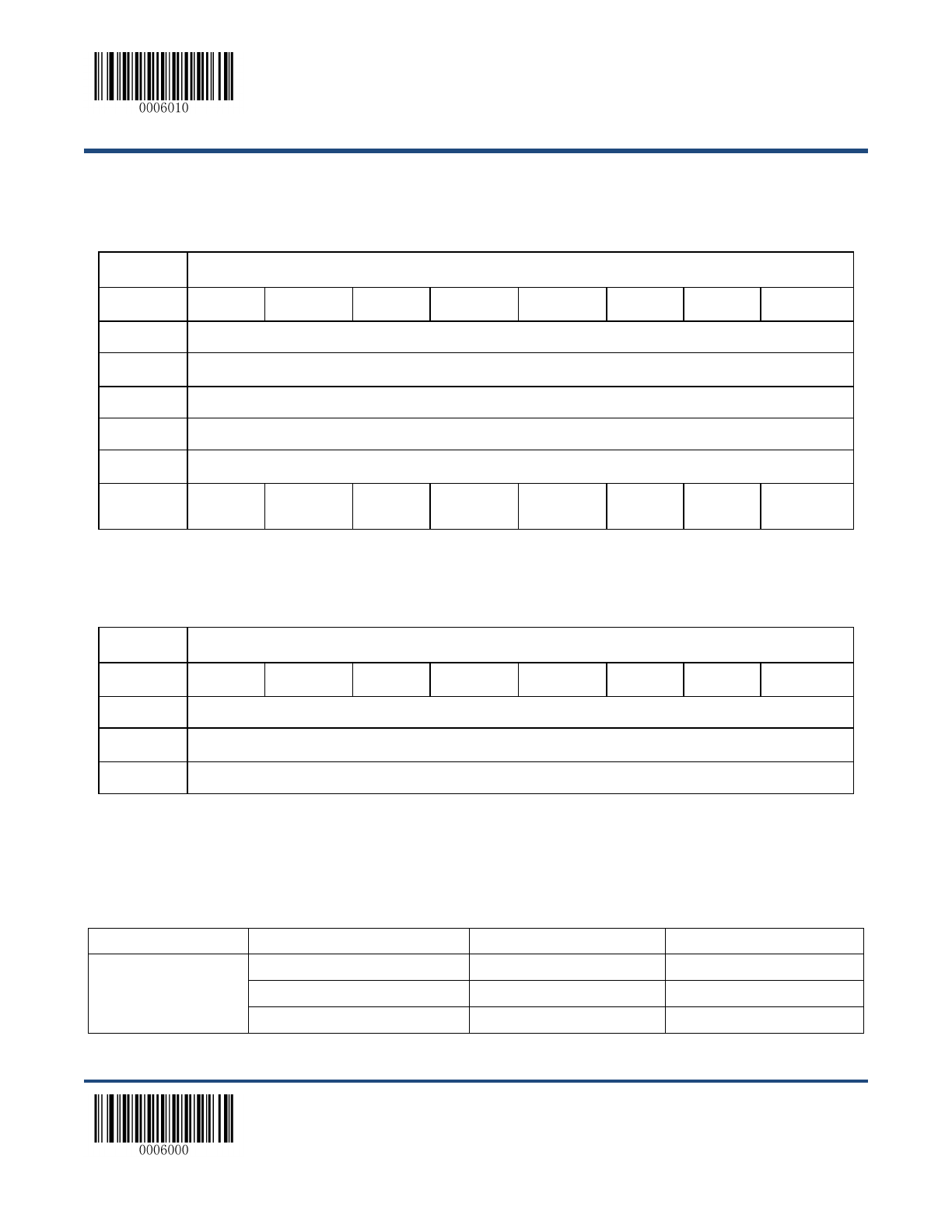
Acquire Scanned Data
After scanning and decoding a barcode, the scanner sends the following input report:
Bit
Byte
7
6
5
4
3
2
1
0
0
Report ID = 0x02
1
Length of the barcode
2-57
Decoded data (1-56)
58-60
AIM ID
61-62
Reserved
63
-
-
-
-
-
-
-
Decoded
Data
Continued
Send Data to the Scanner
This output report is used to send data to the device. All programming commands can be used.
Bit
Byte
7
6
5
4
3
2
1
0
0
Report ID = 0x04
1
Length of the output data
2-63
Output data (1-62)
VID/PID
USB uses VID (Vendor ID) and PID (Product ID) to identify and locate a device. The VID is assigned by
USB Implementers Forum. Newland’s vendor ID is 1EAB (Hex). A PID is assigned to each interface.
Product
Interface
PID (Hex)
PID (Dec)
HR3260 Cordless
USB HID-KBW
0C03
3075
USB COM Port Emulation
0C06
3078
USB HID-POS
0C10
3088

【Enter Setup】
51 **【Exit Setup】
Chapter 5 Symbologies
Introduction
Every symbology (barcode type) has its own unique attributes. This chapter provides programming
barcodes for configuring the scanner so that it can identify various barcode symbologies. The more
symbologies you enable, the slower your scanner decodes. It is recommended to disable those that are
rarely used to improve the performance of the scanner.
Note: Maximum barcode length supported by the scanner is 1024 bytes.
General Settings
Disable All Symbologies
If the Disable All Symbologies feature is enabled, the scanner can only identify the programming
barcodes.
【Disable All Symbologies】
Enable All Symbologies
If the Enable All Symbologies feature is enabled, the scanner can read all compatible barcode
symbologies as well as the programming barcodes.
【Enable All Symbologies】

【Enter Setup】
**【Exit Setup】 52
Enable 1D Symbologies
【Enable 1D Symbologies】
Disable 1D Symbologies
【Disable 1D Symbologies】
Enable 2D Symbologies
【Enable 2D Symbologies】
Disable 2D Symbologies
【Disable 2D Symbologies】

【Enter Setup】
53 **【Exit Setup】
Video Reverse
Regular barcode: Dark image on a bright background.
Inverse barcode: Bright image on a dark background.
The examples of regular barcode and inverse barcode are shown below.
Regular Barcode
Inverse Barcode
Video Reverse is used to allow the scanner to read barcodes that are inverted.
Video Reverse ON: Read both regular barcodes and inverse barcodes.
Video Reverse OFF: Read regular barcodes only.
The scanner shows a slight decrease in scanning speed when Video Reverse is ON.
【Video Reverse ON】
**【Video Reverse OFF】

【Enter Setup】
**【Exit Setup】 54
Code 128
Restore Factory Defaults
【Restore the Factory Defaults of Code 128】
Enable/Disable Code 128
**【Enable Code 128】
【Disable Code 128】
If the scanner fails to identify Code 128 barcodes, you may first try this solution by
scanning the Enter Setup barcode and then Enable Code 128 barcode.
【Enter Setup】
55 **【Exit Setup】
Set Length Range for Code 128
The scanner can be configured to only decode Code 128 barcodes with lengths that fall between
(inclusive) the minimum and maximum lengths. To accomplish it, you need to set the minimum and
maximum lengths.
【Set the Minimum Length (Default: 1)】
【Set the Maximum Length (Default: 127)】
Maximum length of a 1D barcode should not exceed 127 bytes. If minimum length is
set to be greater than maximum length, the scanner only decodes Code 128 barcodes
with either the minimum or maximum length. If minimum length is same as maximum
length, only Code 128 barcodes with that length are to be decoded.
Set the scanner to decode Code 128 barcodes containing between 8 and 12
characters:
1. Scan the Enter Setup barcode.
2. Scan the Set the Minimum Length barcode.
3. Scan the numeric barcode “8”. (See the Digit Barcodes in Appendix)
4. Scan the Save barcode. (See the Save/Cancel Barcodes in Appendix)
5. Scan the Set the Maximum Length barcode.
6. Scan the numeric barcode “1”.
7. Scan the numeric barcode “2”.
8. Scan the Save barcode.
9. Scan the Exit Setup barcode.
【Enter Setup】
**【Exit Setup】 56
EAN-8
Restore Factory Defaults
【Restore the Factory Defaults of EAN-8】
Enable/Disable EAN-8
**【Enable EAN-8】
【Disable EAN-8】
Transmit Check Digit
EAN-8 is 8 digits in length with the last one as its check digit used to verify the integrity of the data.
**【Transmit EAN-8 Check Digit】
【Do Not Transmit EAN-8 Check Digit】
【Enter Setup】
57 **【Exit Setup】
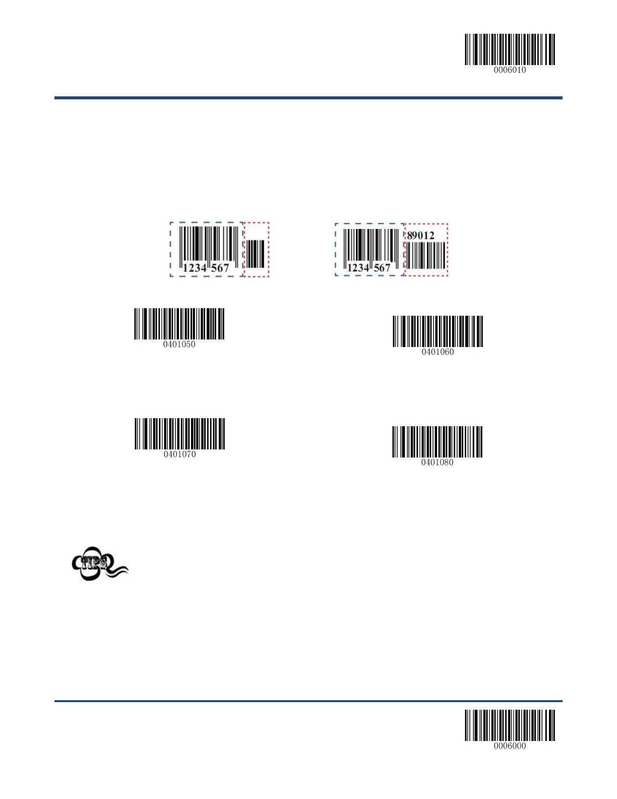
Add-On Code
An EAN-8 barcode can be augmented with a two-digit or five-digit add-on code to form a new one. In the
examples below, the part surrounded by blue dotted line is an EAN-8 barcode while the part circled by red
dotted line is add-on code.
**【Disable 2-Digit Add-On Code】
【Enable 2-Digit Add-On Code】
**【Disable 5-Digit Add-On Code】
【Enable 5-Digit Add-On Code】
Enable 2-Digit Add-On Code/ Enable 5-Digit Add-On Code: The scanner decodes
a mix of EAN-8 barcodes with and without 2-digit/5-digit add-on codes.
Disable 2-Digit Add-On Code/ Disable 5-Digit Add-On Code: The scanner decodes
EAN-8 and ignores the add-on code when presented with an EAN-8 plus add-on
barcode. It can also decode EAN-8 barcodes without add-on codes.

【Enter Setup】
**【Exit Setup】 58
Add-On Code Required
EAN-8 Add-On Code Required: The scanner only decodes EAN-8 barcodes that contain add-on codes.
EAN-8 Add-On Code Not Required: The scanner decodes a mix of EAN-8 barcodes with and without
add-on codes.
【EAN-8 Add-On Code Required】
**【EAN-8 Add-On Code Not Required】
EAN-8 Extension
Disable EAN-8 Zero Extend: Transmit EAN-8 barcodes as is.
Enable EAN-8 Zero Extend: Add five leading zeros to decoded EAN-8 barcodes to extend to 13 digits.
**【Disable EAN-8 Zero Extend】
【Enable EAN-8 Zero Extend】
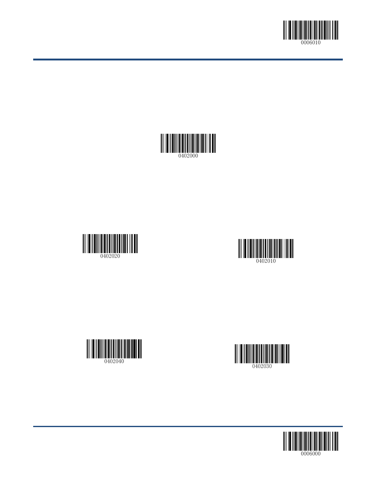
【Enter Setup】
59 **【Exit Setup】
EAN-13
Restore Factory Defaults
**【Restore the Factory Defaults of EAN-13】
Enable/Disable EAN-13
**【Enable EAN-13】
【Disable EAN-13】
Transmit Check Digit
**【Transmit EAN-13 Check Digit】
【Do Not Transmit EAN-13 Check Digit】
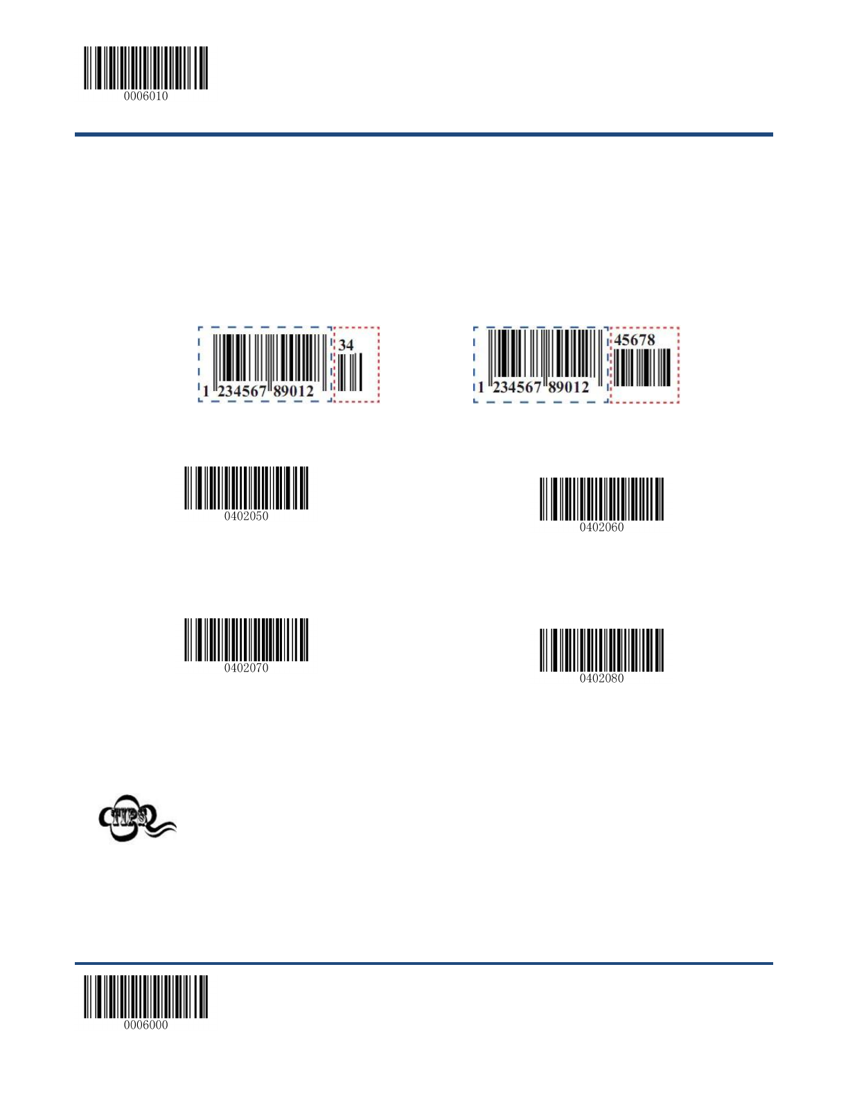
【Enter Setup】
**【Exit Setup】 60
Add-On Code
An EAN-13 barcode can be augmented with a two-digit or five-digit add-on code to form a new one. In the
examples below, the part surrounded by blue dotted line is an EAN-13 barcode while the part circled by
red dotted line is add-on code.
**【Disable 2-Digit Add-On Code】
【Enable 2-Digit Add-On Code】
**【Disable 5-Digit Add-On Code】
【Enable 5-Digit Add-On Code】
Enable 2-Digit Add-On Code/ Enable 5-Digit Add-On Code: The scanner decodes
a mix of EAN-13 barcodes with and without 2-digit/5-digit add-on codes.
Disable 2-Digit Add-On Code/ Disable 5-Digit Add-On Code: The scanner decodes
EAN-13 and ignores the add-on code when presented with an EAN-13 plus add-on
barcode. It can also decode EAN-13 barcodes without add-on codes.

【Enter Setup】
61 **【Exit Setup】
Add-On Code Required
EAN-13 Add-On Code Required: The scanner only decodes EAN-13 barcodes that contain add-on
codes.
EAN-13 Add-On Code Not Required: The scanner decodes a mix of EAN-13 barcodes with and without
add-on codes.
【EAN-13 Add-On Code Required】
**【EAN-13 Add-On Code Not Required】

【Enter Setup】
**【Exit Setup】 62
UPC-E
Restore Factory Defaults
**【Restore the Factory Defaults of UPC-E】
Enable/Disable UPC-E
**【Enable UPC-E】
【Disable UPC-E】
If the scanner fails to identify UPC-E barcodes, you may first try this solution by
scanning the Enter Setup barcode and then Enable UPC-E barcode.
Transmit Check Digit
UPC-E is 8 digits in length with the last one as its check digit used to verify the integrity of the data.
**【Transmit UPC-E Check Digit】
【Do Not Transmit UPC-E Check Digit】
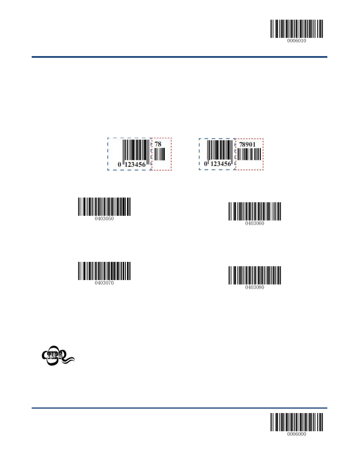
【Enter Setup】
63 **【Exit Setup】
Add-On Code
A UPC-E barcode can be augmented with a two-digit or five-digit add-on code to form a new one. In the
examples below, the part surrounded by blue dotted line is a UPC-E barcode while the part circled by red
dotted line is add-on code.
**【Disable 2-Digit Add-On Code】
【Enable 2-Digit Add-On Code】
**【Disable 5-Digit Add-On Code】
【Enable 5-Digit Add-On Code】
Enable 2-Digit Add-On Code/ Enable 5-Digit Add-On Code: The scanner decodes
a mix of UPC-E barcodes with and without 2-digit/5-digit add-on codes.
Disable 2-Digit Add-On Code/ Disable 5-Digit Add-On Code: The scanner decodes
UPC-E and ignores the add-on code when presented with a UPC-E plus add-on
barcode. It can also decode UPC-E barcodes without add-on codes.

【Enter Setup】
**【Exit Setup】 64
Add-On Code Required
UPC-E Add-On Code Required: The scanner only decodes UPC-E barcodes that contain add-on
codes.
UPC-E Add-On Code Not Required: The scanner decodes a mix of UPC-E barcodes with and without
add-on codes.
【UPC-E Add-On Code Required】
**【UPC-E Add-On Code Not Required】
Transmit System Character “0”
The first character of UPC-E barcode is the system character “0”.
**【Do Not Transmit System Character “0”】
【Transmit System Character “0”】

【Enter Setup】
65 **【Exit Setup】
UPC-E Extension
Disable UPC-E Extend: Transmit UPC-E barcodes as is.
Enable UPC-E Extend: Extend UPC-E barcodes to make them compatible in length to UPC-A.
**【Disable UPC-E Extend】
【Enable UPC-E Extend】
【Enter Setup】
**【Exit Setup】 66
UPC-A
Restore Factory Defaults
Restore the Factory Defaults of UPC-A】
Enable/Disable UPC-A
**【Enable UPC-A】
【Disable UPC-A】
If the scanner fails to identify UPC-A barcodes, you may first try this solution by scanning
the Enter Setup barcode and then Enable UPC-A barcode.
Transmit Check Digit
UPC-A is 12 digits in length with the last one as its check digit used to verify the integrity of the data.
**【Transmit UPC-A Check Digit】
【Do Not Transmit UPC-A Check Digit】
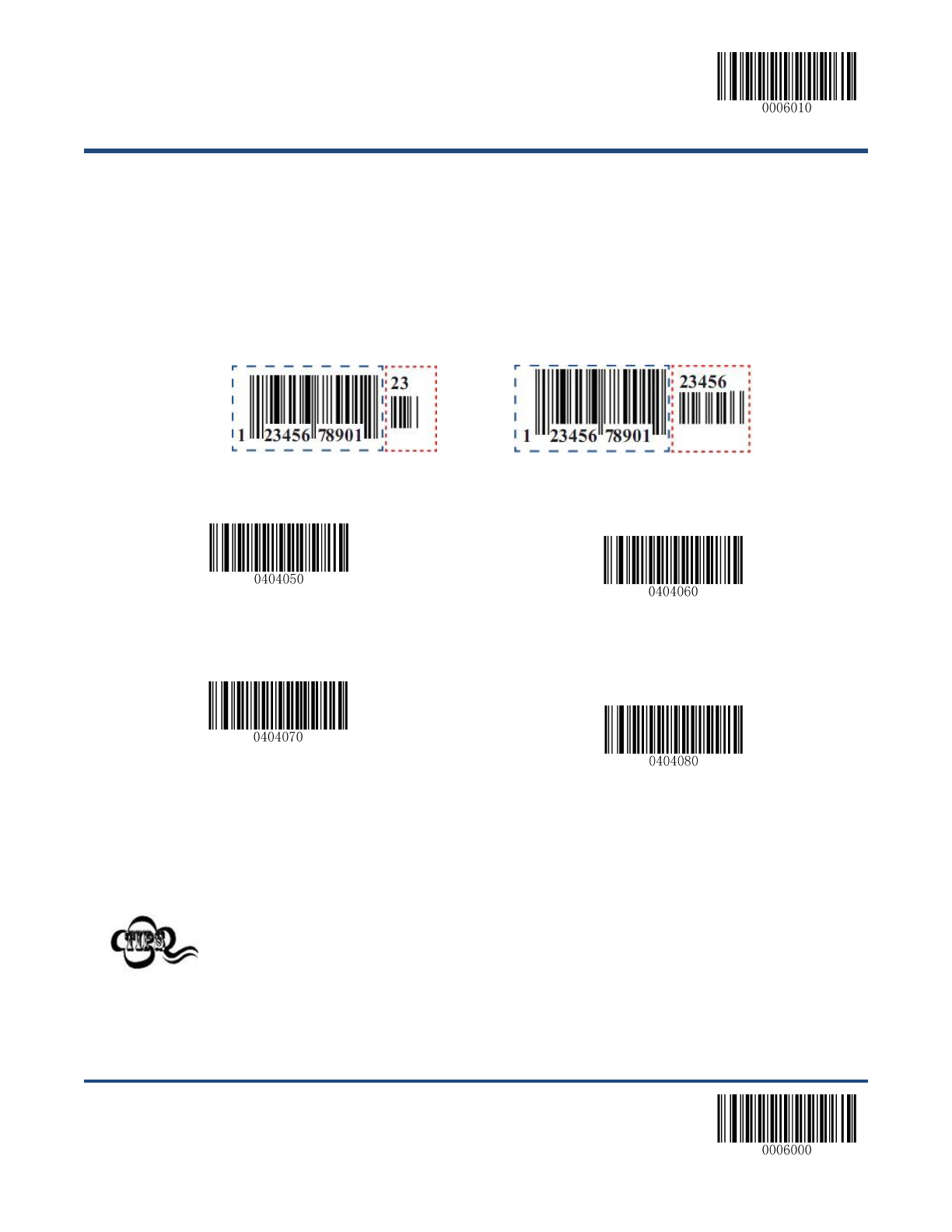
【Enter Setup】
67 **【Exit Setup】
Add-On Code
A UPC-A barcode can be augmented with a two-digit or five-digit add-on code to form a new one. In the
examples below, the part surrounded by blue dotted line is a UPC-A barcode while the part circled by red
dotted line is add-on code.
**【Disable 2-Digit Add-On Code】
【Enable 2-Digit Add-On Code】
**【Disable 5-Digit Add-On Code】
【Enable 5-Digit Add-On Code】
Enable 2-Digit Add-On Code/ Enable 5-Digit Add-On Code: The scanner decodes
a mix of UPC-A barcodes with and without 2-digit/5-digit add-on codes.
Disable 2-Digit Add-On Code/ Disable 5-Digit Add-On Code: The scanner decodes
UPC-A and ignores the add-on code when presented with a UPC-A plus add-on
barcode. It can also decode UPC-A barcodes without add-on codes.

【Enter Setup】
**【Exit Setup】 68
Add-On Code Required
UPC-A Add-On Code Required: The scanner only decodes UPC-A barcodes that contain add-on
codes.
UPC-A Add-On Code Not Required: The scanner decodes a mix of UPC-A barcodes with and without
add-on codes.
【UPC-A Add-On Code Required】
**【UPC-A Add-On Code Not Required】
Transmit Preamble Character “0”
The preamble character “0” is part of the UPC-A barcode.
**【Do Not Transmit Preamble Character “0”】
【Transmit Preamble Character “0”】
The preamble character “0” usually does not appear in printed UPC-A barcodes.
【Enter Setup】
69 **【Exit Setup】
Interleaved 2 of 5
Restore Factory Defaults
【Restore the Factory Defaults of Interleaved 2 of 5】
Enable/Disable Interleaved 2 of 5
**【Enable Interleaved 2 of 5】
【Disable Interleaved 2 of 5】
If the scanner fails to identify Interleaved 2 of 5 barcodes, you may first try this solution
by scanning the Enter Setup barcode and then Enable Interleaved 2 of 5 barcode.
【Enter Setup】
**【Exit Setup】 70
Set Length Range for Interleaved 2 of 5
The scanner can be configured to only decode Interleaved 2 of 5 barcodes with lengths that fall between
(inclusive) the minimum and maximum lengths. To accomplish it, you need to set the minimum and
maximum lengths.
【Set the Minimum Length (Default: 6)】
【Set the Maximum Length (Default: 100)】
Maximum length of a 1D barcode should not exceed 127 bytes. If minimum length is
set to be greater than maximum length, the scanner only decodes Interleaved 2 of 5
barcodes with either the minimum or maximum length. If minimum length is same as
maximum length, only Interleaved 2 of 5 barcodes with that length are to be decoded.
Set the scanner to decode Interleaved 2 of 5 barcodes containing between 8
and 12 characters:
1. Scan the Enter Setup barcode.
2. Scan the Set the Minimum Length barcode.
3. Scan the numeric barcode “8”. (See the Digit Barcodes in Appendix)
4. Scan the Save barcode. (See the Save/Cancel Barcodes in Appendix)
5. Scan the Set the Maximum Length barcode.
6. Scan the numeric barcode “1”.
7. Scan the numeric barcode “2”.
8. Scan the Save barcode.
9. Scan the Exit Setup barcode.
【Enter Setup】
71 **【Exit Setup】
Check Digit Verification
A check digit is optional for Interleaved 2 of 5 and can be added as the last digit. It is a calculated value
used to verify the integrity of the data.
Disable: The scanner transmits Interleaved 2 of 5 barcodes as is.
Do Not Transmit Check Digit After Verification: The scanner checks the integrity of all Interleaved 2 of
5 barcodes to verify that the data complies with the check digit algorithm. Barcodes passing the check will
be transmitted except the last digit, whereas those failing it will not be transmitted.
Transmit Check Digit After Verification: The scanner checks the integrity of all Interleaved 2 of 5
barcodes to verify that the data complies with the check digit algorithm. Barcodes passing the check will
be transmitted, whereas those failing it will not be transmitted.
Since Interleaved 2 of 5 must always have an even number of digits, a zero may need to be added as the
first digit when the check digit is added. The check digit is automatically generated when making
Interleaved 2 of 5 barcodes.
**【Disable】
【Do Not Transmit Check Digit After Verification】
【Transmit Check Digit After Verification】
If the Do Not Transmit Check Digit After Verification option is enabled, Interleaved 2 of
5 barcodes with a length that is less than the configured minimum length after having the
check digit excluded will not be decoded. (For example, when the Do Not Transmit Check
Digit After Verification option is enabled and the minimum length is set to 4, Interleaved 2
of 5 barcodes with a total length of 4 characters including the check digit cannot be read.)

【Enter Setup】
**【Exit Setup】 72
ITF-14
ITF-14 is a special kind of Interleaved 2 of 5 with a length of 14 characters and the last character as the
check character.
【Restore the Factory Defaults of ITF-14】
**【Disable ITF-14】
【Enable ITF-14 But Do Not Transmit Check Digit】
【Enable ITF-14 and Transmit Check Digit】
It is advisable not to enable ITF-14 and Interleaved 2 of 5 at the same time.

【Enter Setup】
73 **【Exit Setup】
ITF-6
ITF-6 is a special kind of Interleaved 2 of 5 with a length of 6 characters and the last character as the
check character.
【Restore the Factory Defaults of ITF-6】
**【Disable ITF-6】
【Enable ITF-6 But Do Not Transmit Check Digit】
【Enable ITF-6 and Transmit Check Digit】
It is advisable not to enable ITF-6 and Interleaved 2 of 5 at the same time.
【Enter Setup】
**【Exit Setup】 74
Matrix 2 of 5
Restore Factory Defaults
【Restore the Factory Defaults of Matrix 2 of 5】
Enable/Disable Matrix 2 of 5
【Enable Matrix 2 of 5】
**【Disable Matrix 2 of 5】
If the scanner fails to identify Matrix 2 of 5 barcodes, you may first try this solution by
scanning the Enter Setup barcode and then Enable Matrix 2 of 5 barcode.

【Enter Setup】
75 **【Exit Setup】
Set Length Range for Matrix 2 of 5
The scanner can be configured to only decode Matrix 2 of 5 barcodes with lengths that fall between
(inclusive) the minimum and maximum lengths. To accomplish it, you need to set the minimum and
maximum lengths.
【Set the Minimum Length (Default: 6)】
【Set the Maximum Length (Default: 127)】
Maximum length of a 1D barcode should not exceed 127 bytes. If minimum length is
set to be greater than maximum length, the scanner only decodes Matrix 2 of 5
barcodes with either the minimum or maximum length. If minimum length is same as
maximum length, only Matrix 2 of 5 barcodes with that length are to be decoded.
Set the scanner to decode Matrix 2 of 5 barcodes containing between 8 and 12
characters:
1. Scan the Enter Setup barcode.
2. Scan the Set the Minimum Length barcode.
3. Scan the numeric barcode “8”. (See the Digit Barcodes in Appendix)
4. Scan the Save barcode. (See the Save/Cancel Barcodes in Appendix)
5. Scan the Set the Maximum Length barcode.
6. Scan the numeric barcode “1”.
7. Scan the numeric barcode “2”.
8. Scan the Save barcode.
9. Scan the Exit Setup barcode.
【Enter Setup】
**【Exit Setup】 76
Check Digit Verification
A check digit is optional for Matrix 2 of 5 and can be added as the last digit. It is a calculated value used to
verify the integrity of the data.
Disable: The scanner transmits Matrix 2 of 5 barcodes as is.
Do Not Transmit Check Digit After Verification: The scanner checks the integrity of all Matrix 2 of 5
barcodes to verify that the data complies with the check digit algorithm. Barcodes passing the check will
be transmitted except the last digit, whereas those failing it will not be transmitted.
Transmit Check Digit After Verification: The scanner checks the integrity of all Matrix 2 of 5 barcodes
to verify that the data complies with the check digit algorithm. Barcodes passing the check will be
transmitted, whereas those failing it will not be transmitted.
Since Matrix 2 of 5 must always have an even number of digits, a zero may need to be added as the first
digit when the check digit is added. The check digit is automatically generated when making Matrix 2 of 5
barcodes.
【Disable】
**【Do Not Transmit Check Digit After Verification】
【Transmit Check Digit After Verification】
If the Do Not Transmit Check Digit After Verification option is enabled, Matrix 2 of 5
barcodes with a length that is less than the configured minimum length after having
the check digit excluded will not be decoded. (For example, when the Do Not
Transmit Check Digit After Verification option is enabled and the minimum length is
set to 4, Matrix 2 of 5 barcodes with a total length of 4 characters including the check
digit cannot be read.)
【Enter Setup】
77 **【Exit Setup】
Code 39
Restore Factory Defaults
【Restore the Factory Defaults of Code 39】
Enable/Disable Code 39
**【Enable Code 39】
【Disable Code 39】
If the scanner fails to identify Code 39 barcodes, you may first try this solution by
scanning the Enter Setup barcode and then Enable Code 39 barcode.
Transmit Start/Stop Character
Code 39 uses an asterisk (*) for both the start and the stop characters. You can choose whether or not to
transmit the start/stop characters by scanning the appropriate barcode below.
**【Transmit Start/Stop Character】
【Do Not Transmit Start/Stop Character】

【Enter Setup】
**【Exit Setup】 78
Set Length Range for Code 39
The scanner can be configured to only decode Code 39 barcodes with lengths that fall between (inclusive)
the minimum and maximum lengths. To accomplish it, you need to set the minimum and maximum
lengths.
【Set the Minimum Length (Default: 1)】
【Set the Maximum Length (Default: 127)】
Maximum length of a 1D barcode should not exceed 127 bytes. If minimum length is
set to be greater than maximum length, the scanner only decodes Code 39 barcodes
with either the minimum or maximum length. If minimum length is same as maximum
length, only Code 39 barcodes with that length are to be decoded.
Set the scanner to decode Code 39 barcodes containing between 8 and 12
characters:
1. Scan the Enter Setup barcode.
2. Scan the Set the Minimum Length barcode.
3. Scan the numeric barcode “8”. (See the Digit Barcodes in Appendix)
4. Scan the Save barcode. (See the Save/Cancel Barcodes in Appendix)
5. Scan the Set the Maximum Length barcode.
6. Scan the numeric barcode “1”.
7. Scan the numeric barcode “2”.
8. Scan the Save barcode.
9. Scan the Exit Setup barcode.
【Enter Setup】
79 **【Exit Setup】
Check Digit Verification
A check digit is optional for Code 39 and can be added as the last digit. It is a calculated value used to
verify the integrity of the data.
Disable: The scanner transmits Code 39 barcodes as is.
Do Not Transmit Check Digit After Verification: The scanner checks the integrity of all Code 39
barcodes to verify that the data complies with the check digit algorithm. Barcodes passing the check will
be transmitted except the last digit, whereas those failing it will not be transmitted.
Transmit Check Digit After Verification: The scanner checks the integrity of all Code 39 barcodes to
verify that the data complies with the check digit algorithm. Barcodes passing the check will be
transmitted, whereas those failing it will not be transmitted.
**【Disable】
【Do Not Transmit Check Digit After Verification】
【Transmit Check Digit After Verification】
If the Do Not Transmit Check Digit After Verification option is enabled, Code 39
barcodes with a length that is less than the configured minimum length after having
the check digit excluded will not be decoded. (For example, when the Do Not
Transmit Check Digit After Verification option is enabled and the minimum length is
set to 4, Code 39 barcodes with a total length of 4 characters including the check digit
cannot be read.)

【Enter Setup】
**【Exit Setup】 80
Enable/Disable Code 39 Full ASCII
The scanner can be configured to identify all ASCII characters by scanning the appropriate barcode
below.
【Disable Code 39 Full ASCII】
**【Enable Code 39 Full ASCII】
【Enter Setup】
81 **【Exit Setup】
Codabar
Restore Factory Defaults
【Restore the Factory Defaults of Codabar】
Enable/Disable Codabar
**【Enable Codabar】
【Disable Codabar】
If the scanner fails to identify Codabar barcodes, you may first try this solution by
scanning the Enter Setup barcode and then Enable Codabar barcode.

【Enter Setup】
**【Exit Setup】 82
Set Length Range for Codabar
The scanner can be configured to only decode Codabar barcodes with lengths that fall between (inclusive) the minimum
and maximum lengths. To accomplish it, you need to set the minimum and maximum lengths.
【Set the Minimum Length (Default: 1)】
【Set the Maximum Length (Default: 127)】
Maximum length of a 1D barcode should not exceed 127 bytes. If minimum length is
set to be greater than maximum length, the scanner only decodes Codabar barcodes
with either the minimum or maximum length. If minimum length is same as maximum
length, only Codabar barcodes with that length are to be decoded.
Set the scanner to decode Codabar barcodes containing between 8 and 12
characters:
1. Scan the Enter Setup barcode.
2. Scan the Set the Minimum Length barcode.
3. Scan the numeric barcode “8”. (See the Digit Barcodes in Appendix)
4. Scan the Save barcode. (See the Save/Cancel Barcodes in Appendix)
5. Scan the Set the Maximum Length barcode.
6. Scan the numeric barcode “1”.
7. Scan the numeric barcode “2”.
8. Scan the Save barcode.
9. Scan the Exit Setup barcode.

【Enter Setup】
83 **【Exit Setup】
Check Digit Verification
A check digit is optional for Codabar and can be added as the last digit. It is a calculated value used to
verify the integrity of the data.
Disable: The scanner transmits Codabar barcodes as is.
Do Not Transmit Check Digit After Verification: The scanner checks the integrity of all Codabar
barcodes to verify that the data complies with the check digit algorithm. Barcodes passing the check will
be transmitted except the last digit, whereas those failing it will not be transmitted.
Transmit Check Digit After Verification: The scanner checks the integrity of all Codabar barcodes to
verify that the data complies with the check digit algorithm. Barcodes passing the check will be
transmitted, whereas those failing it will not be transmitted.
**【Disable】
【Do Not Transmit Check Digit After Verification】
【Transmit Check Digit After Verification】
If the Do Not Transmit Check Digit After Verification option is enabled, Codabar
barcodes with a length that is less than the configured minimum length after having
the check digit excluded will not be decoded. (For example, when the Do Not
Transmit Check Digit After Verification option is enabled and the minimum length is
set to 4, Codabar barcodes with a total length of 4 characters including the check digit
cannot be read.)
【Enter Setup】
**【Exit Setup】 84
Start/Stop Character
You can set the start/stop characters and choose whether or not to transmit the start/stop characters by
scanning the appropriate barcode below.
【Transmit Start/Stop Character】
**【Do Not Transmit Start/Stop Character】
**【ABCD/ABCD as the Start/Stop Character】
【Start/Stop Character in Uppercase】
【ABCD/TN*E as the Start/Stop Character】
【Start/Stop Character in Lowercase】

【Enter Setup】
85 **【Exit Setup】
Code 93
Restore Factory Defaults
【Restore the Factory Defaults of Code 93】
Enable/Disable Code 93
**【Enable Code 93】
【Disable Code 93】
If the scanner fails to identify Code 93 barcodes, you may first try this solution by
scanning the Enter Setup barcode and then Enable Code 93 barcode.

【Enter Setup】
**【Exit Setup】 86
Set Length Range for Code 93
The scanner can be configured to only decode Code 93 barcodes with lengths that fall between (inclusive)
the minimum and maximum lengths. To accomplish it, you need to set the minimum and maximum
lengths.
【Set the Minimum Length (Default: 3)】
【Set the Maximum Length (Default: 127)】
Maximum length of a 1D barcode should not exceed 127 bytes. If minimum length is
set to be greater than maximum length, the scanner only decodes Code 93 barcodes
with either the minimum or maximum length. If minimum length is same as maximum
length, only Code 93 barcodes with that length are to be decoded.
Set the scanner to decode Code 93 barcodes containing between 8 and 12
characters:
1. Scan the Enter Setup barcode.
2. Scan the Set the Minimum Length barcode.
3. Scan the numeric barcode “8”. (See the Digit Barcodes in Appendix)
4. Scan the Save barcode. (See the Save/Cancel Barcodes in Appendix)
5. Scan the Set the Maximum Length barcode.
6. Scan the numeric barcode “1”.
7. Scan the numeric barcode “2”.
8. Scan the Save barcode.
9. Scan the Exit Setup barcode.

【Enter Setup】
87 **【Exit Setup】
Check Digit Verification
Check digits are optional for Code 93 and can be added as the last two digits, which are calculated values
used to verify the integrity of the data.
Disable: The scanner transmits Code 93 barcodes as is.
Do Not Transmit Check Digit After Verification: The scanner checks the integrity of all Code 93
barcodes to verify that the data complies with the check digit algorithm. Barcodes passing the checks will
be transmitted except the last two digits, whereas those failing them will not be transmitted.
Transmit Check Digit After Verification: The scanner checks the integrity of all Code 93 barcodes to
verify that the data complies with the check digit algorithm. Barcodes passing the checks will be
transmitted, whereas those failing them will not be transmitted.
【Disable】
**【Do Not Transmit Check Digit After Verification】
【Transmit Check Digit After Verification】
If the Do Not Transmit Check Digit After Verification option is enabled, Code 93
barcodes with a length that is less than the configured minimum length after having
the two check digits excluded will not be decoded. (For example, when the Do Not
Transmit Check Digit After Verification option is enabled and the minimum length is
set to 4, Code 93 barcodes with a total length of 4 characters including the two check
digits cannot be read.)

【Enter Setup】
**【Exit Setup】 88
UCC/EAN-128
Restore Factory Defaults
【Restore the Factory Defaults of UCC/EAN-128】
Enable/Disable UCC/EAN-128
**【Enable UCC/EAN-128】
【Disable UCC/EAN-128】
If the scanner fails to identify UCC/EAN-128 barcodes, you may first try this solution
by scanning the Enter Setup barcode and then Enable UCC/EAN-128 barcode.

【Enter Setup】
89 **【Exit Setup】
Set Length Range for UCC/EAN-128
The scanner can be configured to only decode UCC/EAN-128 barcodes with lengths that fall between
(inclusive) the minimum and maximum lengths. To accomplish it, you need to set the minimum and
maximum lengths.
【Set the Minimum Length (Default: 1)】
【Set the Maximum Length (Default: 127)】
Maximum length of a 1D barcode should not exceed 127 bytes. If minimum length is
set to be greater than maximum length, the scanner only decodes UCC/EAN-128
barcodes with either the minimum or maximum length. If minimum length is same as
maximum length, only UCC/EAN-128 barcodes with that length are to be decoded.
Set the scanner to decode UCC/EAN-128 barcodes containing between 8 and 12
characters:
1. Scan the Enter Setup barcode.
2. Scan the Set the Minimum Length barcode.
3. Scan the numeric barcode “8”. (See the Digit Barcodes in Appendix)
4. Scan the Save barcode. (See the Save/Cancel Barcodes in Appendix)
5. Scan the Set the Maximum Length barcode.
6. Scan the numeric barcode “1”.
7. Scan the numeric barcode “2”.
8. Scan the Save barcode.
9. Scan the Exit Setup barcode.

【Enter Setup】
**【Exit Setup】 90
GS1 Databar
Restore Factory Defaults
【Restore the Factory Defaults of GS1 Databar】
Enable/Disable GS1 Databar
**【Enable GS1 Databar】
【Disable GS1 Databar】
If the scanner fails to identify GS1 Databar barcodes, you may first try this solution by
scanning the Enter Setup barcode and then Enable GS1 Databar barcode.
Transmit Application Identifier “01”
**【Transmit Application Identifier “01”】
【Do Not Transmit Application Identifier “01”】

【Enter Setup】
91 **【Exit Setup】
Code 11
Restore Factory Defaults
【Restore the Factory Defaults of Code 11】
Enable/Disable Code 11
**【Enable Code 11】
【Disable Code 11】
If the scanner fails to identify Code 11 barcodes, you may first try this solution by
scanning the Enter Setup barcode and then Enable Code 11 barcode.

【Enter Setup】
**【Exit Setup】 92
Set Length Range for Code 11
The scanner can be configured to only decode Code 11 barcodes with lengths that fall between (inclusive)
the minimum and maximum lengths. To accomplish it, you need to set the minimum and maximum
lengths.
【Set the Minimum Length (Default: 2)】
【Set the Maximum Length (Default: 127】
Maximum length of a 1D barcode should not exceed 127 bytes. If minimum length is
set to be greater than maximum length, the scanner only decodes Code 11 barcodes
with either the minimum or maximum length. If minimum length is same as maximum
length, only Code 11 barcodes with that length are to be decoded.
Set the scanner to decode Code 11 barcodes containing between 8 and 12
characters:
1. Scan the Enter Setup barcode.
2. Scan the Set the Minimum Length barcode.
3. Scan the numeric barcode “8”. (See the Digit Barcodes in Appendix)
4. Scan the Save barcode. (See the Save/Cancel Barcodes in Appendix)
5. Scan the Set the Maximum Length barcode.
6. Scan the numeric barcode “1”.
7. Scan the numeric barcode “2”.
8. Scan the Save barcode.
9. Scan the Exit Setup barcode.
【Enter Setup】
93 **【Exit Setup】
Check Digit Verification
Check digits are optional for Code 11 and can be added as the last one or two digits, which are calculated
values used to verify the integrity of the data.
If the Disable option is enabled, the scanner transmits Code 11 barcodes as is.
【Disable】
【One Check Digit, MOD11 (Len<=10) 】
【Two Check Digits, MOD11/MOD11(Len>10)】
**【One Check Digit, MOD11】
【One Check Digit, MOD11 (Len<=10) 】
【Two Check Digits, MOD11/MOD9 (Len>10)】
【Two Check Digits, MOD11/MOD11】
**【Do Not Transmit Check Digit】
【Two Check Digits, MOD11/MOD9】
【Transmit Check Digit】
If you select a check digit algorithm and the Do Not Transmit Check Digit option,
Code 11 barcodes with a length that is less than the configured minimum length after
having the check digit(s) excluded will not be decoded. (For example, when the One
Check Digit, MOD11 and Do Not Transmit Check Digit options are enabled and the
minimum length is set to 4, Code 11 barcodes with a total length of 4 characters
including the check digit cannot be read.)
【Enter Setup】
**【Exit Setup】 94
ISBN
Restore Factory Defaults
【Restore the Factory Defaults of ISBN】
Enable/Disable ISBN
【Enable ISBN】
**【Disable ISBN】
If the scanner fails to identify ISBN barcodes, you may first try this solution by
scanning the Enter Setup barcode and then Enable ISBN barcode.
Set ISBN Format
**【ISBN-13】
【ISBN-10】

【Enter Setup】
95 **【Exit Setup】
Add-On Code
An ISBN barcode can be augmented with a two-digit or five-digit add-on code to form a new one.
【Enable 2-Digit Add-On Code】
**【Disable 2-Digit Add-On Code】
【Enable 5-Digit Add-On Code】
**【Disable 5-Digit Add-On Code】
Enable 2-Digit Add-On Code/ Enable 5-Digit Add-On Code: The scanner decodes
a mix of ISBN barcodes with and without 2-digit/5-digit add-on codes.
Disable 2-Digit Add-On Code/ Disable 5-Digit Add-On Code: The scanner decodes
ISBN and ignores the add-on code when presented with an ISBN plus add-on barcode.
It can also decode ISBN barcodes without add-on codes.

【Enter Setup】
**【Exit Setup】 96
Add-On Code Required
ISBN Add-On Code Required: The scanner only decodes ISBN barcodes that contain add-on codes.
ISBN Add-On Code Not Required: The scanner decodes a mix of ISBN barcodes with and without
add-on codes.
【ISBN Add-On Code Required】
**【ISBN Add-On Code Not Required】

【Enter Setup】
97 **【Exit Setup】
ISSN
Restore Factory Defaults
【Restore the Factory Defaults of ISSN】
Enable/Disable ISSN
【Enable ISSN】
**【Disable ISSN】
If the scanner fails to identify ISSN barcodes, you may first try this solution by
scanning the Enter Setup barcode and then Enable ISSN barcode.
【Enter Setup】
**【Exit Setup】 98
Add-On Code
An ISSN barcode can be augmented with a two-digit or five-digit add-on code to form a new one.
【Enable 2-Digit Add-On Code】
**【Disable 2-Digit Add-On Code】
【Enable 5-Digit Add-On Code】
**【Disable 5-Digit Add-On Code】
Enable 2-Digit Add-On Code/ Enable 5-Digit Add-On Code: The scanner decodes
a mix of ISSN barcodes with and without 2-digit/5-digit add-on codes.
Disable 2-Digit Add-On Code/ Disable 5-Digit Add-On Code: The scanner decodes
ISSN and ignores the add-on code when presented with an ISSN plus add-on barcode.
It can also decode ISSN barcodes without add-on codes.

【Enter Setup】
99 **【Exit Setup】
Add-On Code Required
ISSN Add-On Code Required: The scanner only decodes ISSN barcodes that contain add-on codes.
ISSN Add-On Code Not Required: The scanner decodes a mix of ISSN barcodes with and without
add-on codes.
【ISSN Add-On Code Required】
**【ISSN Add-On Code Not Required】
【Enter Setup】
**【Exit Setup】 100
AIM-128
Restore Factory Defaults
【Restore the Factory Defaults of AIM-128】
Enable/Disable AIM-128
**【Enable AIM-128】
【Disable AIM-128】
If the scanner fails to identify AIM-128 barcodes, you may first try this solution by
scanning the Enter Setup barcode and then Enable AIM-128 barcode.

【Enter Setup】
101 **【Exit Setup】
Set Length Range for AIM-128
The scanner can be configured to only decode AIM-128 barcodes with lengths that fall between (inclusive)
the minimum and maximum lengths. To accomplish it, you need to set the minimum and maximum
lengths.
【Set the Minimum Length (Default: 1)】
【Set the Maximum Length (Default: 127)】
Maximum length of a 1D barcode should not exceed 127 bytes. If minimum length is
set to be greater than maximum length, the scanner only decodes AIM-128 barcodes
with either the minimum or maximum length. If minimum length is same as maximum
length, only AIM-128 barcodes with that length are to be decoded.
Set the scanner to decode AIM-128 barcodes containing between 8 and 12
characters:
1. Scan the Enter Setup barcode.
2. Scan the Set the Minimum Length barcode.
3. Scan the numeric barcode “8”. (See the Digit Barcodes in Appendix)
4. Scan the Save barcode. (See the Save/Cancel Barcodes in Appendix)
5. Scan the Set the Maximum Length barcode.
6. Scan the numeric barcode “1”.
7. Scan the numeric barcode “2”.
8. Scan the Save barcode.
9. Scan the Exit Setup barcode.

【Enter Setup】
**【Exit Setup】 102
Industrial 25
Restore Factory Defaults
【Restore the Factory Defaults of Industrial 25】
Enable/Disable Industrial 25
**【Enable Industrial 25】
【Disable Industrial 25】
If the scanner fails to identify Industrial 25 barcodes, you may first try this solution by
scanning the Enter Setup barcode and then Enable Industrial 25 barcode.

【Enter Setup】
103 **【Exit Setup】
Set Length Range for Industrial 25
The scanner can be configured to only decode Industrial 25 barcodes with lengths that fall between
(inclusive) the minimum and maximum lengths. To accomplish it, you need to set the minimum and
maximum lengths.
【Set the Minimum Length (Default: 6)】
【Set the Maximum Length (Default: 127)】
Maximum length of a 1D barcode should not exceed 127 bytes. If minimum length is
set to be greater than maximum length, the scanner only decodes Industrial 25
barcodes with either the minimum or maximum length. If minimum length is same as
maximum length, only Industrial 25 barcodes with that length are to be decoded.
Set the scanner to decode Industrial 25 barcodes containing between 8 and 12
characters:
1. Scan the Enter Setup barcode.
2. Scan the Set the Minimum Length barcode.
3. Scan the numeric barcode “8”. (See the Digit Barcodes in Appendix)
4. Scan the Save barcode. (See the Save/Cancel Barcodes in Appendix)
5. Scan the Set the Maximum Length barcode.
6. Scan the numeric barcode “1”.
7. Scan the numeric barcode “2”.
8. Scan the Save barcode.
9. Scan the Exit Setup barcode.
【Enter Setup】
**【Exit Setup】 104
Check Digit Verification
A check digit is optional for Industrial 25 and can be added as the last digit. It is a calculated value used to
verify the integrity of the data.
Disable: The scanner transmits Industrial 25 barcodes as is.
Do Not Transmit Check Digit After Verification: The scanner checks the integrity of all Industrial 25
barcodes to verify that the data complies with the check digit algorithm. Barcodes passing the check will
be transmitted except the last digit, whereas those failing it will not be transmitted.
Transmit Check Digit After Verification: The scanner checks the integrity of all Industrial 25 barcodes
to verify that the data complies with the check digit algorithm. Barcodes passing the check will be
transmitted, whereas those failing it will not be transmitted.
**【Disable】
【Do Not Transmit Check Digit After Verification】
【Transmit Check Digit After Verification】
If the Do Not Transmit Check Digit After Verification option is enabled, Industrial 25
barcodes with a length that is less than the configured minimum length after having
the check digit excluded will not be decoded. (For example, when the Do Not
Transmit Check Digit After Verification option is enabled and the minimum length is
set to 4, Industrial 25 barcodes with a total length of 4 characters including the check
digit cannot be read.)

【Enter Setup】
105 **【Exit Setup】
Standard 25
Restore Factory Defaults
【Restore the Factory Defaults of Standard 25】
Enable/Disable Standard 25
**【Enable Standard 25】
【Disable Standard 25】
If the scanner fails to identify Standard 25 barcodes, you may first try this solution by
scanning the Enter Setup barcode and then Enable Standard 25 barcode.
【Enter Setup】
**【Exit Setup】 106
Set Length Range for Standard 25
The scanner can be configured to only decode Standard 25 barcodes with lengths that fall between
(inclusive) the minimum and maximum lengths. To accomplish it, you need to set the minimum and
maximum lengths.
【Set the Minimum Length (Default: 6)】
【Set the Maximum Length (Default: 127)】
Maximum length of a 1D barcode should not exceed 127 bytes. If minimum length is
set to be greater than maximum length, the scanner only decodes Standard 25
barcodes with either the minimum or maximum length. If minimum length is same as
maximum length, only Standard 25 barcodes with that length are to be decoded.
Set the scanner to decode Standard 25 barcodes containing between 8 and 12
characters:
1. Scan the Enter Setup barcode.
2. Scan the Set the Minimum Length barcode.
3. Scan the numeric barcode “8”. (See the Digit Barcodes in Appendix)
4. Scan the Save barcode. (See the Save/Cancel Barcodes in Appendix)
5. Scan the Set the Maximum Length barcode.
6. Scan the numeric barcode “1”.
7. Scan the numeric barcode “2”.
8. Scan the Save barcode.
9. Scan the Exit Setup barcode.

【Enter Setup】
107 **【Exit Setup】
Check Digit Verification
A check digit is optional for Standard 25 and can be added as the last digit. It is a calculated value used to
verify the integrity of the data.
Disable: The scanner transmits Standard 25 barcodes as is.
Do Not Transmit Check Digit After Verification: The scanner checks the integrity of all Standard 25
barcodes to verify that the data complies with the check digit algorithm. Barcodes passing the check will
be transmitted except the last digit, whereas those failing it will not be transmitted.
Transmit Check Digit After Verification: The scanner checks the integrity of all Standard 25 barcodes
to verify that the data complies with the check digit algorithm. Barcodes passing the check will be
transmitted, whereas those failing it will not be transmitted.
**【Disable】
【Do Not Transmit Check Digit After Verification】
【Transmit Check Digit After Verification】
If the Do Not Transmit Check Digit After Verification option is enabled, Standard 25
barcodes with a length that is less than the configured minimum length after having
the check digit excluded will not be decoded. (For example, when the Do Not
Transmit Check Digit After Verification option is enabled and the minimum length is
set to 4, Standard 25 barcodes with a total length of 4 characters including the check
digit cannot be read.)

【Enter Setup】
**【Exit Setup】 108
Plessey
Restore Factory Defaults
【Restore the Factory Defaults of Plessey】
Enable/Disable Plessey
【Enable Plessey】
**【Disable Plessey】
If the scanner fails to identify Plessey barcodes, you may first try this solution by
scanning the Enter Setup barcode and then Enable Plessey barcode.

【Enter Setup】
109 **【Exit Setup】
Set Length Range for Plessey
The scanner can be configured to only decode Plessey barcodes with lengths that fall between (inclusive)
the minimum and maximum lengths. To accomplish it, you need to set the minimum and maximum
lengths.
【Set the Minimum Length (Default: 1)】
【Set the Maximum Length (Default: 127)】
Maximum length of a 1D barcode should not exceed 127 bytes. If minimum length is
set to be greater than maximum length, the scanner only decodes Plessey barcodes
with either the minimum or maximum length. If minimum length is same as maximum
length, only Plessey barcodes with that length are to be decoded.
Set the scanner to decode Plessey barcodes containing between 8 and 12
characters:
1. Scan the Enter Setup barcode.
2. Scan the Set the Minimum Length barcode.
3. Scan the numeric barcode “8”. (See the Digit Barcodes in Appendix)
4. Scan the Save barcode. (See the Save/Cancel Barcodes in Appendix)
5. Scan the Set the Maximum Length barcode.
6. Scan the numeric barcode “1”.
7. Scan the numeric barcode “2”.
8. Scan the Save barcode.
9. Scan the Exit Setup barcode.

【Enter Setup】
**【Exit Setup】 110
Check Digit Verification
Check digits are optional for Plessey and can be added as the last two digits, which are calculated values
used to verify the integrity of the data.
Disable: The scanner transmits Plessey barcodes as is.
Do Not Transmit Check Digit After Verification: The scanner checks the integrity of all Plessey
barcodes to verify that the data complies with the check digit algorithm. Barcodes passing the checks will
be transmitted except the last two digits, whereas those failing them will not be transmitted.
Transmit Check Digit After Verification: The scanner checks the integrity of all Plessey barcodes to
verify that the data complies with the check digit algorithm. Barcodes passing the checks will be
transmitted, whereas those failing them will not be transmitted.
【Disable】
**【Do Not Transmit Check Digit After Verification】
【Transmit Check Digit After Verification】
If the Do Not Transmit Check Digit After Verification option is enabled, Plessey
barcodes with a length that is less than the configured minimum length after having
the check digits excluded will not be decoded. (For example, when the Do Not
Transmit Check Digit After Verification option is enabled and the minimum length is
set to 4, Plessey barcodes with a total length of 4 characters including the check digits
cannot be read.)

【Enter Setup】
111 **【Exit Setup】
MSI-Plessey
Restore Factory Defaults
【Restore the Factory Defaults of MSI-Plessey】
Enable/Disable MSI-Plessey
【Enable MSI-Plessey】
**【Disable MSI-Plessey】
If the scanner fails to identify MSI-Plessey barcodes, you may first try this solution by
scanning the Enter Setup barcode and then Enable MSI-Plessey barcode.

【Enter Setup】
**【Exit Setup】 112
Set Length Range for MSI-Plessey
The scanner can be configured to only decode MSI-Plessey barcodes with lengths that fall between
(inclusive) the minimum and maximum lengths. To accomplish it, you need to set the minimum and
maximum lengths.
【Set the Minimum Length (Default: 2)】
【Set the Maximum Length (Default: 127)】
Maximum length of a 1D barcode should not exceed 127 bytes. If minimum length is
set to be greater than maximum length, the scanner only decodes MSI-Plessey
barcodes with either the minimum or maximum length. If minimum length is same as
maximum length, only MSI-Plessey barcodes with that length are to be decoded.
Set the scanner to decode MSI-Plessey barcodes containing between 8 and 12
characters:
1. Scan the Enter Setup barcode.
2. Scan the Set the Minimum Length barcode.
3. Scan the numeric barcode “8”. (See the Digit Barcodes in Appendix)
4. Scan the Save barcode. (See the Save/Cancel Barcodes in Appendix)
5. Scan the Set the Maximum Length barcode.
6. Scan the numeric barcode “1”.
7. Scan the numeric barcode “2”.
8. Scan the Save barcode.
9. Scan the Exit Setup barcode.
【Enter Setup】
113 **【Exit Setup】
Check Digit Verification
Check digits are optional for MSI-Plessey and can be added as the last one or two digits, which are
calculated values used to verify the integrity of the data.
If the Disable option is enabled, the scanner transmits MSI-Plessey barcodes as is.
【Disable】
【Two Check Digits, MOD10/MOD11】
**【One Check Digit, MOD10】
**【Do Not Transmit Check Digit】
【Two Check Digits, MOD10/MOD10】
【Transmit Check Digit】
If you select a check digit algorithm and the Do Not Transmit Check Digit option,
MSI-Plessey barcodes with a length that is less than the configured minimum length
after having the check digit(s) excluded will not be decoded. (For example, when the
One Check Digit, MOD11 and Do Not Transmit Check Digit options are enabled
and the minimum length is set to 4, MSI-Plessey barcodes with a total length of 4
characters including the check digit cannot be read.)

【Enter Setup】
**【Exit Setup】 114
PDF417
Restore Factory Defaults
**【Restore the Factory Defaults of PDF417】
Enable/Disable PDF417
**【Enable PDF417】
【Disable PDF417】
If the scanner fails to identify PDF417 barcodes, you may first try this solution by
scanning the Enter Setup barcode and then Enable PDF417 barcode.

【Enter Setup】
115 **【Exit Setup】
Set Length Range for PDF417
The scanner can be configured to only decode PDF417 barcodes with lengths that fall between (inclusive)
the minimum and maximum lengths. To accomplish it, you need to set the minimum and maximum
lengths.
【Set the Minimum Length (Default: 1)】
【Set the Maximum Length (Default: 1024)】
Maximum length of a 2D barcode should not exceed 1024 bytes. Minimum length is
not allowed to be greater than maximum length. If you only want to read PDF417
barcodes with a specific length, set both minimum and maximum lengths to be that
desired length.
Set the scanner to decode PDF417 barcodes containing between 8 and 12
bytes:
1. Scan the Enter Setup barcode.
2. Scan the Set the Minimum Length barcode.
3. Scan the numeric barcode “8”. (See the Digit Barcodes in Appendix)
4. Scan the Save barcode. (See the Save/Cancel Barcodes in Appendix)
5. Scan the Set the Maximum Length barcode.
6. Scan the numeric barcode “1”.
7. Scan the numeric barcode “2”.
8. Scan the Save barcode.
9. Scan the Exit Setup barcode.

【Enter Setup】
**【Exit Setup】 116
QR Code
Restore Factory Defaults
【Restore the Factory Defaults of QR Code】
Enable/Disable QR Code
**【Enable QR Code】
【Disable QR Code】
If the scanner fails to identify QR Code barcodes, you may first try this solution by
scanning the Enter Setup barcode and then Enable QR Code barcode.

【Enter Setup】
117 **【Exit Setup】
Set Length Range for QR Code
The scanner can be configured to only decode QR Code barcodes with lengths that fall between
(inclusive) the minimum and maximum lengths. To accomplish it, you need to set the minimum and
maximum lengths.
【Set the Minimum Length (Default: 1)】
【Set the Maximum Length (Default: 1024)】
Maximum length of a 2D barcode should not exceed 1024 bytes. Minimum length is
not allowed to be greater than maximum length. If you only want to read QR Code
barcodes with a specific length, set both minimum and maximum lengths to be that
desired length.
Set the scanner to decode QR Code barcodes containing between 8 and 12
bytes:
1. Scan the Enter Setup barcode.
2. Scan the Set the Minimum Length barcode.
3. Scan the numeric barcode “8”. (See the Digit Barcodes in Appendix)
4. Scan the Save barcode. (See the Save/Cancel Barcodes in Appendix)
5. Scan the Set the Maximum Length barcode.
6. Scan the numeric barcode “1”.
7. Scan the numeric barcode “2”.
8. Scan the Save barcode.
9. Scan the Exit Setup barcode.

【Enter Setup】
**【Exit Setup】 118
Micro QR
**【Enable Micro QR】
【Disable Micro QR】

【Enter Setup】
119 **【Exit Setup】
Data Matrix
Restore Factory Defaults
【Restore the Factory Defaults of Data Matrix】
Enable/Disable Data Matrix
**【Enable Data Matrix】
【Disable Data Matrix】
If the scanner fails to identify Data Matrix barcodes, you may first try this solution by
scanning the Enter Setup barcode and then Enable Data Matrix barcode.

【Enter Setup】
**【Exit Setup】 120
Set Length Range for Data Matrix
The scanner can be configured to only decode Data Matrix barcodes with lengths that fall between
(inclusive) the minimum and maximum lengths. To accomplish it, you need to set the minimum and
maximum lengths.
【Set the Minimum Length (Default: 1)】
【Set the Maximum Length (Default: 1024)】
Maximum length of a 2D barcode should not exceed 1024 bytes. Minimum length is
not allowed to be greater than maximum length. If you only want to read Data Matrix
barcodes with a specific length, set both minimum and maximum lengths to be that
desired length.
Set the scanner to decode Data Matrix barcodes containing between 8 and 12
bytes:
1. Scan the Enter Setup barcode.
2. Scan the Set the Minimum Length barcode.
3. Scan the numeric barcode “8”. (See the Digit Barcodes in Appendix)
4. Scan the Save barcode. (See the Save/Cancel Barcodes in Appendix)
5. Scan the Set the Maximum Length barcode.
6. Scan the numeric barcode “1”.
7. Scan the numeric barcode “2”.
8. Scan the Save barcode.
9. Scan the Exit Setup barcode.
【Enter Setup】
121 **【Exit Setup】
Rectangular Barcode
Data Matrix has two formats:
Square barcodes having the same amount of modules in length and width: 10*10, 12*12.... 144*144.
Rectangular barcodes having different amounts of models in length and width: 6*16, 6*14... 14*22.
**【Enable Rectangular Barcode】
【Disable Rectangular Barcode】
Mirror Image
**【Decode Mirrored DM】
【Do Not Decode Mirrored DM】

【Enter Setup】
**【Exit Setup】 122
Chapter 6 Prefix & Suffix
Introduction
A 1D barcode could contain digits, letters, symbols, etc. A 2D barcode could contain more data, such as
Chinese characters and other multi-byte characters. However, in real applications, they do not and should
not have all information we need, such as barcode type, data acquisition time and delimiter, in order to
keep the barcodes short and flexible.
Preffix and suffix are how to fulfill the needs mentioned above. They can be added, removed and modified
while the original barcode data remains intact.
【Enter Setup】
123 **【Exit Setup】
General Settings
Enable/Disable All Prefix/Suffix
Disable All Prefix/Suffix: Transmit barcode data with no prefix/suffix.
Enable All Prefix/Suffix: Allow user to append Code ID prefix, AIM ID prefix, custom prefix/suffix and
terminating character to the barcode data before the transmission.
【Disable All Prefix/Suffix】
【Enable All Prefix/Suffix】
Prefix Sequences
2 prefix sequence options:
【Code ID + Custom + AIM ID】
**【Custom + Code ID + AIM ID】
【Enter Setup】
**【Exit Setup】 124
Custom Prefix
Enable/Disable Custom Prefix
If custom prefix is enabled, you are allowed to append to the data a user-defined prefix that cannot
exceed 10 characters. For example, if the custom prefix is “AB” and the barcode data is “123”, the Host
will receive “AB123”.
**【Disable Custom Prefix】
【Enable Custom Prefix】
Set Custom Prefix
To set a custom prefix, scan the Set Custom Prefix barcode and then the numeric barcodes
corresponding to the hexadecimal value of a desired prefix. To save the settings, scan the Save barcode.
Note: A custom prefix cannot exceed 10 characters.
【Set Custom Prefix】
Set the custom prefix to “CODE” (its hexadecimal value is 0x43/0x4F/0x44/0x45):
1. Scan the Enter Setup barcode.
2. Scan the Set Custom Prefix barcode.
3. Scan the numeric barcodes “4”,“3”,“4”,“F”,“4”,“4”,“4” and “5”. (See the Digit
Barcodes in Appendix)
4. Scan the Save barcode. (See the Save/Cancel Barcodes in Appendix)
5. Scan the Enable Custom Prefix barcode.
6. Scan the Exit Setup barcode.

【Enter Setup】
125 **【Exit Setup】
AIM ID Prefix
AIM (Automatic Identification Manufacturers) ID defines symbology identifier (For the details, see the AIM
ID Table in Appendix). If AIM ID prefix is enabled, the scanner will add the symbology identifier before
the scanned data after decoding.
**【Disable AIM ID Prefix】
【Enable AIM ID Prefix】
AIM ID is not user programmable.
Code ID Prefix
Code ID can also be used to identify barcode type. Unlike AIM ID, Code ID is user programmable. Code
ID can only consist of one or two English letters.
**【Disable Code ID Prefix】
【Enable Code ID Prefix】

【Enter Setup】
**【Exit Setup】 126
Restore All Default Code IDs
For the information of default Code IDs, see the Code ID Table in Appendix.
【Restore All Default Code IDs】
Modify Code ID
See the examples below to learn how to modify a Code ID and restore the default Code IDs of all
symbologies.
Modify PDF417 Code ID to be “p” (its hexadecimal value is 0x70):
1. Scan the Enter Setup barcode.
2. Scan the Modify PDF417 Code ID barcode.
3. Scan the numeric barcodes “7” and “0”. (See the Digit Barcodes in
Appendix)
4. Scan the Save barcode. (See the Save/Cancel Barcodes in Appendix)
5. Scan the Exit Setup barcode.
Restore the default Code IDs of all symbologies:
1. Scan the Enter Setup barcode.
2. Scan the Restore All Default Code IDs barcode.
3. Scan the Exit Setup barcode.
【Enter Setup】
127 **【Exit Setup】
【Modify PDF417 Code ID】
【Modify Data Matrix Code ID】
【Modify QR Code ID】
【Modify Matrix 25 Code ID】
【Modify ISSN Code ID】
【Modify AIM-128 Code ID】
【Modify EAN-8 Code ID】
【Modify ITF-6 Code ID】
【Enter Setup】
**【Exit Setup】 128
【Modify EAN-13 Code ID】
【Modify Code 39 Code ID】
【Modify UPC-E Code ID】
【Modify Codabar Code ID】
【Modify UPC-A Code ID】
【Modify Code 93 Code ID】
【Modify Interleaved 2 of 5 Code ID】
【Modify Code 128 Code ID】
【Enter Setup】
129 **【Exit Setup】
【Modify ITF-14 Code ID】
【Modify ISBN Code ID】
【Modify UCC/EAN-128 Code ID】
【Modify Industrial 25 Code ID】
【Modify Code 11 Code ID】
【Modify Standard 25 Code ID】
【Modify Plessey Code ID】
【Modify MSI-Plessey Code ID】
【Modify GS1 Databar Code ID】
【Enter Setup】
**【Exit Setup】 130
Custom Suffix
Enable/Disable Custom Suffix
If custom suffix is enabled, you are allowed to append to the data a user-defined suffix that cannot exceed
10 characters. For example, if the custom suffix is “AB” and the barcode data is “123”, the Host will
receive “123AB”.
**【Disable Custom Suffix】
【Enable Custom Suffix】
Set Custom Suffix
To set a custom suffix, scan the Set Custom Suffix barcode and then the numeric barcodes
corresponding to the hexadecimal value of a desired suffix. To save the settings, scan the Save barcode.
Note: A custom suffix cannot exceed 10 characters.
【Set Custom Suffix】
Set the custom suffix to “CODE” (its hexadecimal value is 0x43/0x4F/0x44/0x45):
1. Scan the Enter Setup barcode.
2. Scan the Set Custom Suffix barcode.
3. Scan the numeric barcodes “4”,“3”,“4”,“F”,“4”,“4”,“4” and “5”. (See the Digit
Barcodes in Appendix)
4. Scan the Save barcode. (See the Save/Cancel Barcodes in Appendix)
5. Scan the Enable Custom Suffix barcode.
6. Scan the Exit Setup barcode.
【Enter Setup】
131 **【Exit Setup】
Terminating Character Suffix
Enable/Disable Terminating Character Suffix
A terminating character such as carriage return (CR) or carriage return/line feed pair (CRLF) can only be
used to mark the end of data, which means nothing can be added after it.
【Disable Terminating Character Suffix】
**【Enable Terminating Character Suffix】
Set Terminating Character Suffix
The scanner provides a shortcut for setting the terminating character suffix to 0x0D or 0x0D,0x0A by
scanning the following barcode.
【Terminating Character 0x0D】
**【Terminating Character 0x0D,0x0A】

【Enter Setup】
**【Exit Setup】 132
To set a terminating character suffix, scan the Set Terminating Character Suffix barcode and the
numeric barcodes representing the hexadecimal value of a desired terminating character and then scan
the Save barcode. Refer to the ASCII Table in Appendix for hexadecimal values of terminating
characters.
Note: A terminating character suffix cannot exceed 2 characters.
【Set Terminating Character Suffix】
Set the terminating character suffix to 0x0A:
1. Scan the Enter Setup barcode.
2. Scan the Set Terminating Character Suffix barcode.
3. Scan the numeric barcodes “0” and “A”. (See the Digit Barcodes in
Appendix)
4. Scan the Save barcode. (See the Save/Cancel Barcodes in Appendix)
5. Scan the Exit Setup barcode.

【Enter Setup】
133 **【Exit Setup】
Chapter 7 Ambient Illumination
Ambient lighting conditions may vary from one operating environment to another, such as fluorescent lit
warehouses or sunlit open spaces. Fluorescent lights may flicker when using AC power source in
50-60Hz. Usually indoor illuminance is around 1,000 lux while outdoor illuminance may reach 60,000 lux
or even over 100,000 lux.
Two options are provided for ambient illumination settings:
Normal Illuminance: applicable to most indoor/outdoor environments.
High Illuminance: applicable to special enviroments with super-intense light source.
Change to this settings will not take effect until the scanner reboots or wakes from sleep.
**【Normal Illuminance (0~60000lux)】
【High Illuminance (60000~120000lux)】
134
Appendix
Digit Barcodes
After scanning numeric barcode(s), you need to scan the Save barcode to save the data.
0~5
【0】
【1】
【2】
【3】
【4】
【5】
135
6~9
【6】
【7】
【8】
【9】
136
A~F
【A】
【B】
【C】
【D】
【E】
【F】
137
Save/Cancel Barcodes
After reading numeric barcode(s), you need to scan the Save barcode to save the data. If you scan the
wrong digit(s), you can either scan the Cancel barcode and then start the configuration all over again, or
scan the Delete the Last Digit barcode and then the correct digit, or scan the Delete All Digits barcode
and then the digits you want.
For instance, after reading the Maximum Length barcode and numeric barcodes “1”, “2” and “3”, you
scan:
Delete the Last Digit: The last digit “3” will be removed.
Delete All Digits: All digits “123” will be removed.
Cancel: The maximum length configuration will be cancelled. And the scaner is still in the setup
mode.
【Save】
【Cancel】
【Delete the Last Digit】
【Delete All Digits】
138
Factory Defaults Table
Parameter
Factory Default
Remark
System Settings
Barcode Programming
Disabled
Auto Power-Off Timeout
5 minutes
Applicable to Manual
mode only
Illumination
Normal
Aiming
Normal
Startup Beep
Enabled
Good Read Beep
Notification
Enabled
Beep Type
Type 3
Beep Volume
Loud
NGR (Not Good Read) Message
Do not transmit
Null
Scan Mode
Manual mode
Manual Mode
Decode Session Timeout
3,000ms
Applicable to Trigger mode,
Sense mode and Continuous
mode
1~3,600,000ms; 0: Infinite.
Timeout between Decodes
(Same Barcode)
Disabled
1,500ms
0~65,535ms
Sense Mode
Decode Session Timeout
3,000ms
Applicable to Trigger mode,
Sense mode and Continuous
mode
1~3,600,000ms; 0: Infinite.
Image Stabilization Timeout
500ms
0~1,600ms
Operation after Good Decode
Pause after good decode
Timeout between Decodes
(Same Barcode)
Enabled
1,500ms
0~65,535ms
Threshold Value of
Illumination Change
2
1~20
Continuous Mode
Decode Session Timeout
3,000ms
Applicable to Trigger mode,
Sense mode and Continuous
mode
1~3,600,000ms; 0: Infinite.
Timeout between Decodes
1,000ms
0~65,535ms
139
Parameter
Factory Default
Remark
Communication Settings
Wireless Communication Mode
Synchronous Mode
USB HID-KBW
USB HID-KBW
RS-232
Baud Rate
115200
Parity Check
None
Number of Data Bits
8
Number of Stop Bits
1
Hardware Flow Control
Disabled
USB HID-KBW
Examine KBW Connection
Enabled
USB Country Keyboard Type
U.S.
Inter-Keystroke Delay
No delay
Convert Case
No conversion
Emulate ALT + Keypad
Disabled
Function Key Mapping
Disabled
Emulate Numeric Keypad
Disabled
Prefix & Suffix
Prefix Sequence
Custom+Code ID+AIM ID
Custom Prefix
Disabled
Null
AIM ID Prefix
Disabled
Code ID Prefix
Disabled
Custom Suffix
Disabled
Null
Terminating Character Suffix
Enabled
0x0D, 0x0A
Carriage Return/Line
Feed
Ambient Illumination
Ambient Illumination
Normal illuminance

140
Parameter
Factory Default
Remark
Symbologies
Video Reverse
Disabled
Applicable to all
symbologies.
Code 128
Code 128
Enabled
Maximum Length
127
Minimum Length
1
UCC/EAN-128
UCC/EAN-128
Enabled
Maximum Length
127
Minimum Length
1
AIM-128
AIM-128
Enabled
Maximum Length
127
Minimum Length
1
EAN-8
EAN-8
Enabled
Check Digit
Transmit
2-Digit Add-On Code
Disabled
5-Digit Add-On Code
Disabled
Add-On Code
Not required
Extend to EAN-13
Disabled
EAN-13
EAN-13
Enabled
Check Digit
Transmit
2-Digit Add-On Code
Disabled
5-Digit Add-On Code
Disabled
Add-On Code
Not required
ISSN
ISSN
Disabled
2-Digit Add-On Code
Disabled
5-Digit Add-On Code
Disabled
Add-On Code
Not required

141
Parameter
Factory Default
Remark
ISBN
ISBN
Disabled
ISBN Format
ISBN-13
2-Digit Add-On Code
Disabled
5-Digit Add-On Code
Disabled
Add-On Code
Not required
UPC-E
UPC-E
Enabled
Check Digit
Transmit
2-Digit Add-On Code
Disabled
5-Digit Add-On Code
Disabled
Add-On Code
Not required
Extend to UPC-A
Disabled
System Character “0”
Do not transmit
UPC-A
UPC-A
Enabled
Check Digit
Transmit
2-Digit Add-On Code
Disabled
5-Digit Add-On Code
Disabled
Add-On Code
Not required
Preamble Character “0”
Do not transmit
Interleaved 2 of 5
Interleaved 2 of 5
Enabled
Check Digit Verification
Disabled
Check Digit
Do not transmit
Maximum Length
100
Minimum Length
6
ITF-6
ITF-6
Disabled
Check Digit
Do not transmit

142
Parameter
Factory Default
Remark
ITF-14
ITF-14
Disabled
Check Digit
Do not transmit
出
Matrix 2 of 5
Matrix 2 of 5
Disabled
Check Digit Verification
Enabled
Check Digit
Do not transmit
Maximum Length
127
Minimum Length
6
Industrial 2 of 5
Industrial 2 of 5
Enabled
Check Digit Verification
Disabled
Check Digit
Do not transmit
Maximum Length
127
Minimum Length
6
Standard 2 of 5
Standard 2 of 5
Enabled
Check Digit Verification
Disabled
Check Digit
Do not transmit
Maximum Length
127
Minimum Length
6
Code 39
Code 39
Enabled
Check Digit Verification
Disabled
Check Digit
Do not transmit
Start/Stop Character
Transmit
Code 39 Full ASCII
Enabled
Maximum Length
127
Minimum Length
1

143
Parameter
Factory Default
Remark
Codabar
Codabar
Enabled
Check Digit Verification
Disabled
Check Digit
Do not transmit
Start/Stop Character
Do not transmit
Start/Stop Character Format
ABCD/ABCD
Maximum Length
127
Minimum Length
1
Code 93
Code 93
Enabled
Check Digit Verification
Enabled
Check Digit
Do not transmit
Maximum Length
127
Minimum Length
3
GS1 Databar
GS1 Databar
Enabled
Application Identifier “01”
Transmit
Code 11
Code 11
Enabled
Check Digit Verification
One check digit, MOD11
Check Digit
Do not transmit
Maximum Length
127
Minimum Length
2
Plessey
Plessey
Disabled
Check Digit Verification
Enabled
Check Digit
Do not transmit
Maximum Length
127
Minimum Length
1
144
Parameter
Factory Default
Remark
MSI-Plessey
MSI-Plessey
Disabled
Check Digit Verification
One check digit, MOD10
Check Digit
Do not transmit
Maximum Length
127
Minimum Length
2
PDF 417
PDF 417
Enabled
Maximum Length
1024
Minimum Length
1
QR Code
QR Code
Enabled
Micro QR
Enabled
Maximum Length
1024
Minimum Length
1
Data Matrix
Data Matrix
Enabled
Rectangular Barcode
Enabled
Mirror Image
Decode
Maximum Length
1024
Minimum Length
1

145
AIM ID Table
Symbology
AIM ID
Remark
EAN-13
]E0
Standard EAN-13
]E3
EAN-13 + 2/5-Digit Add-On Code
E
AN-8
]E4
Standard EAN-8
]E4…]E1…
EAN-8 + 2-Digit Add-On Code
]E4…]E2…
EAN-8 + 5-Digit Add-On Code
UP
C
-
E
]E0
Standard UPC-E
]E3
UPC-E + 2/5-Digit Add-On Code
UP
C
-A
]E0
Standard UPC-A
]E3
UPC-A + 2/5-Digit Add-On Code
Code 128
]C0
Standard Code 128
UCC/EAN-128
]C1
FNC1 is the character right after the start character
AIM-128
]C2
FNC1 is the 2nd character after the start character
ISBT-128
]C4
Interleaved 2 of 5
]I0
No check digit verification
]I1
Transmit check digit after verification
]I3
Do not transmit check digit after verification
I
T
F-6
]I1
Transmit check digit
]I3
Do not transmit check digit
I
T
F-14
]I1
Transmit check digit
]I3
Do not transmit check digit
Industrial 2 of 5
]S0
Not specified
Standard 2 of 5
]R0
No check digit verification
]R8
One check digit, MOD10; do not transmit check digit
]R9
One check digit, MOD10; transmit check digit
Code 39
]A0
Transmit barcodes as is; Full ASCII disabled; no check digit
verification
]A1
One check digit, MOD43; transmit check digit
]A3
One check digit, MOD43; do not transmit check digit
]A4
Full ASCII enabled; no check digit verification
]A5
Full ASCII enabled; transmit check digit
]A7
Full ASCII enabled; do not transmit check digit

146
Symbology
AIM ID
Remark
Codabar
]F0
Standard Codabar
]F2
Transmit check digit after verification
]F4
Do not transmit check digit after verification
Code 93
]G0
Standard Code 93
Code 11
]H0
One check digit MOD11; transmit check digit
]H1
Two check digits, MOD11/MOD11; transmit check digit
]H3
Do not transmit check digit after verification
]H9
No check digit verification
GS1-DataBar (RSS)
]e0
Standard GS1-DataBar
Plessey
]P0
Standard Plessey
MSI-Plessey
]M0
One check digit, MOD10; transmit check digit
]M1
One check digit, MOD10; do not transmit check digit
]M8
Two check digits
]M9
No check digit verification
Matrix 2 of 5
]X0
Specified by the manufacturer
]X1
No check digit verification
]X2
One check digit, MOD10; transmit check digit
]X3
One check digit, MOD11; do not transmit check digit
ISBN
]X4
Standard ISBN
ISSN
]X5
Standard ISSN
PDF417
]L0
Comply with 1994 PDF417 specifications
Data Matrix
]d0
ECC000 - ECC140
]d1
ECC200
]d2
ECC200, FNC1 is the 1st or 5th character after the start character
]d3
ECC200, FNC1 is the 2nd or 6th character after the start character
]d4
ECC200, ECI included
]d5
ECC200, FNC1 is the 1st or 5th character after the start
character,ECI included
]d6
ECC200, FNC1 is the 2nd or 6th character after the start
character,ECI included

147
Symbology
AIM ID
Remark
QR Code
]Q0
QR1
]Q1
2005 version, ECI excluded
]Q2
2005 version, ECI included
]Q3
QR Code 2005, ECI excluded, FNC1 is the 1st character after the
start character
]Q4
QR Code 2005, ECI included, FNC1 is the 1st character after the
start character
]Q5
QR Code 2005,ECI excluded,FNC1 is the 2nd character after the
start character
]Q6
QR Code 2005, ECI included, FNC1 is the 2nd character after
the start character
Reference: ISO/IEC 15424:2008 Information technology – Automatic identification and data capture
techniques – Data Carrier Identifiers (including Symbology Identifiers).

148
Code ID Table
Symbology
Code ID
Code 128
j
UCC/EAN-128
j
AIM-128
f
EAN-8
d
EAN-13
d
ISSN
n
ISBN
B
UPC-E
c
UPC-A
c
Interleaved 2 of 5
e
ITF-6
e
ITF-14
e
Matrix 2 of 5
v
Industrial 2 of 5
D
Standard 2 of 5
s
Code 39
b
Codabar
a
Code 93
i
Code 11
H
Plessey
p
MSI-Plessey
m
GS1 Databar
R
PDF417
r
QR Code
Q
Data Matrix
u

149
ASCII Table
Hex
Dec
Char
00
0
NUL (Null char.)
01
1
SOH (Start of Header)
02
2
STX (Start of Text)
03
3
ETX (End of Text)
04
4
EOT (End of Transmission)
05
5
ENQ (Enquiry)
06
6
ACK (Acknowledgment)
07
7
BEL (Bell)
08
8
BS (Backspace)
09
9
HT (Horizontal Tab)
0a
10
LF (Line Feed)
0b
11
VT (Vertical Tab)
0c
12
FF (Form Feed)
0d
13
CR (Carriage Return)
0e
14
SO (Shift Out)
0f
15
SI (Shift In)
10
16
DLE (Data Link Escape)
11
17
DC1 (XON) (Device Control 1)
12
18
DC2 (Device Control 2)
13
19
DC3 (XOFF) (Device Control 3)
14
20
DC4 (Device Control 4)
15
21
NAK (Negative Acknowledgement)
16
22
SYN (Synchronous Idle)
17
23
ETB (End of Trans. Block)
18
24
CAN (Cancel)
19
25
EM (End of Medium)
1a
26
SUB (Substitute)
1b
27
ESC (Escape)
1c
28
FS (File Separator)
1d
29
GS (Group Separator)

150
Hex
Dec
Char
1e
30
RS (Request to Send)
1f
31
US (Unit Separator)
20
32
SP (Space)
21
33
! (Exclamation Mark)
22
34
" (Double Quote)
23
35
# (Number Sign)
24
36
$ (Dollar Sign)
25
37
% (Percent)
26
38
& (Ampersand)
27
39
` (Single Quote)
28
40
( (Left / Opening Parenthesis)
29
41
) (Right / Closing Parenthesis)
2a
42
* (Asterisk)
2b
43
+ (Plus)
2c
44
, (Comma)
2d
45
- (Minus / Dash)
2e
46
. (Dot)
2f
47
/ (Forward Slash)
30
48
0
31
49
1
32
50
2
33
51
3
34
52
4
35
53
5
36
54
6
37
55
7
38
56
8
39
57
9
3a
58
: (Colon)
3b
59
; (Semi-colon)
3c
60
< (Less Than)
3d
61
= (Equal Sign)

151
Hex
Dec
Char
3e
62
> (Greater Than)
3f
63
? (Question Mark)
40
64
@ (AT Symbol)
41
65
A
42
66
B
43
67
C
44
68
D
45
69
E
46
70
F
47
71
G
48
72
H
49
73
I
4a
74
J
4b
75
K
4c
76
L
4d
77
M
4e
78
N
4f
79
O
50
80
P
51
81
Q
52
82
R
53
83
S
54
84
T
55
85
U
56
86
V
57
87
W
58
88
X
59
89
Y
5a
90
Z
5b
91
[ (Left / Opening Bracket)
5c
92
\ (Back Slash)
5d
93
] (Right / Closing Bracket)

152
Hex
Dec
Char
5e
94
^ (Caret / Circumflex)
5f
95
_ (Underscore)
60
96
' (Grave Accent)
61
97
a
62
98
b
63
99
c
64
100
d
65
101
e
66
102
f
67
103
g
68
104
h
69
105
i
6a
106
j
6b
107
k
6c
108
l
6d
109
m
6e
110
n
6f
111
o
70
112
p
71
113
q
72
114
r
73
115
s
74
116
t
75
117
u
76
118
v
77
119
w
78
120
x
79
121
y
7a
122
z
7b
123
{ (Left/ Opening Brace)
7c
124
| (Vertical Bar)
7d
125
} (Right/Closing Brace)
7e
126
~ (Tilde)
7f
127
DEL (Delete)

153
ASCII Function Key Mapping Table
ASCII Function
ASCII Value (HEX)
No Function Key Mapping
Function Key Mapping
NUL (Null char.)
00
Null
Ctrl+2
SOH (Start of Header)
01
Keypad Enter
Ctrl+A
STX (Start of Text)
02
Caps Lock
Ctrl+B
ETX (End of Text)
03
Null
Ctrl+C
EOT (End of Transmission)
04
Null
Ctrl+D
ENQ (Enquiry)
05
Null
Ctrl+E
ACK (Acknowledgment)
06
Null
Ctrl+F
BEL (Bell)
07
Enter
Ctrl+G
BS (Backspace)
08
Left Arrow
Ctrl+H
HT (Horizontal Tab)
09
Horizontal Tab
Ctrl+I
LF (Line Feed)
0A
Down Arrow
Ctrl+J
VT (Vertical Tab)
0B
Vertical Tab
Ctrl+K
FF (Form Feed)
0C
Delete
Crtl+L
CR (Carriage Return)
0D
Enter
Ctrl+M
SO (Shift Out)
0E
Insert
Ctrl+N
SI (Shift In)
0F
Esc
Ctrl+O
DLE (Data Link Escape)
10
F11
Ctrl+P
DC1 (XON) (Device Control 1)
11
Home
Ctrl+Q
DC2 (Device Control 2)
12
Print Screen
Ctrl+R
DC3 (XOFF) (Device Control 3)
13
Backspace
Ctrl+S
DC4 (Device Control 4)
14
tab+shift
Ctrl+T
NAK (Negative Acknowledgment)
15
F12
Ctrl+U
SYN (Synchronous Idle)
16
F1
Ctrl+V
ETB (End of Trans. Block)
17
F2
Ctrl+W
CAN (Cancel)
18
F3
Ctrl+X
EM (End of Medium)
19
F4
Ctrl+Y
SUB (Substitute)
1A
F5
Ctrl+Z
ESC (Escape)
1B
F6
See the following table
FS (File Separator)
1C
F7
GS (Group Separator)
1D
F8
RS (Request to Send)
1E
F9
US (Unit Separator)
1F
F10

154
ASCII Function Key Mapping Table (Continued)
The function key mappings of the last five characters in the previous table differ from one keyboard layout
to another.
Country/
Keyboard Layout
Function Key Mapping
1B
1C
1D
1E
1F
United States
Ctrl+[
Ctrl+\
Ctrl+]
Ctrl+6
Ctrl+-
Belgium
Ctrl+[
Ctrl+<
Ctrl+]
Ctrl+6
Ctrl+-
Scandinavia
Ctrl+8
Ctrl+<
Ctrl+9
Ctrl+6
Ctrl+-
France
Ctrl+^
Ctrl+8
Ctrl+$
Ctrl+6
Ctrl+=
Germany
Ctrl+Ã
Ctrl++
Ctrl+6
Ctrl+-
Italy
Ctrl+\
Ctrl++
Ctrl+6
Ctrl+-
Switzerland
Ctrl+<
Ctrl+.
Ctrl+6
Ctrl+-
United Kingdom
Ctrl+[
Ctrl+¢
Ctrl+]
Ctrl+6
Ctrl+-
Denmark
Ctrl+8
Ctrl+\
Ctrl+9
Ctrl+6
Ctrl+-
Norway
Ctrl+8
Ctrl+\
Ctrl+9
Ctrl+6
Ctrl+-
Spain
Ctrl+[
Ctrl+\
Ctrl+]
Ctrl+6
Ctrl+-

155
Warning Statement
This equipment has been tested and found to comply with the limits for a Class B digital device,
pursuant to part 15 of the FCC Rules. These limits are designed to provide reasonable protection
against harmful interference in a residential installation. This equipment generates, uses and can
radiate radio frequency energy and, if not installed and used in accordance with the instructions,
may cause harmful interference to radio communications. However, there is no guarantee that
interference will not occur in a particular installation. If this equipment does cause harmful
interference to radio or television reception, which can be determined by turning the equipment off
and on, the user is encouraged to try to correct the interference by one or more of the following
measures:
• Reorient or relocate the receiving antenna.
• Increase the separation between the equipment and receiver.
• Connect the equipment into an outlet on a circuit different from that to which the receiver is
connected.
• Consult the dealer or an experienced radio/TV technician for help.
Caution: Any changes or modifications to this device not explicitly approved by manufacturer
could void your authority to operate this equipment.
This device complies with part 15 of the FCC Rules. Operation is subject to the following two
conditions: (1) This device may not cause harmful interference, and (2) this device must accept any
interference received, including interference that may cause undesired operation.
The device has been evaluated to meet general RF exposure requirement. The device can be used in
portable exposure condition without restriction.

Headquarters
Fujian Newland Auto-ID Tech. Co., Ltd.
3F, Building A, No.1, Rujiang West Rd., Mawei, Fuzhou,
Fujian, China 350015
TEL: +86 - (0) 591-83978605
FAX: +86 - (0) 591-83979216
E-mail: marketing@nlscan.com
WEB:www.nlscan.com
Newland Europe BV
Rolweg 25, 4104 AV Culemborg, The Netherlands
TEL: +31 (0) 345 87 00 33
FAX: +31 (0) 345 87 00 39
Email: info@newland-id.com
WEB: www.newland-id.com
Tech Support: tech-support@newland-id.com
Newland North America Inc.
Address: 46559 Fremont Blvd., Fremont, CA 94538, USA
TEL: 510 490 3888
Fax: 510 490 3887
Email: info@newlandna.com
WEB: www.newlandna.com
Newland Taiwan Inc.
7F-6, No. 268, Liancheng Rd., Jhonghe Dist. 235, New
Taipei City, Taiwan
TEL: +886 2 7731 5388
FAX: +886 2 7731 5389
Email: info@newland-id.com.tw
WEB: www.newland-id.com.tw