Fujian Newland Auto ID Tech NLS-MT70 Portable (Barcode) Data Collector User Manual NLS MT70 User Guide
Fujian Newland Auto-ID Tech Co., Ltd. Portable (Barcode) Data Collector NLS MT70 User Guide
User Manual
NLS-
Portab
l
User G
MT70
l
e (Bar
c
uide
c
ode) D
a
a
ta Col
l
l
ector

© 2012 by Fujian Newland Auto-ID Tech Co., Ltd. All rights reserved.
Please carefully read the manual before use the product, and effectively to protect the safety of products operation. Please
keep this manual after reading properly and save for the next reading.
Do not disassemble the terminal or tearing the seal label on the terminal. Otherwise, Fujian Newland Auto-ID Tech. Co., Ltd.
does not assume responsibility for the warranty or replacement.
The pictures in this manual are for reference only. If the individual picture from the actual product was different with this manual,
please refer to actual product. Regarding to the product modification and update, Newland Auto-ID Tech. Co., Ltd. reserves the
right to make changes to any software or product to improve reliability, function, or design at any time without notice.
This manual contains all the information is protected by copyright. Any Company and individuals should not in any way or
reason for any form of extract, copy, sell all or part of this document without written permission.
Fujian Newland Auto-ID Tech. Co., Ltd
Newland Science & Technology Park, No.1 Rujiang West Rd., Mawei district, Fuzhou, Fujian, China
Web :http://www.nlscan.com
Table of Contents
Chapter 1 About This Guide ........................................................................................................................................................................... 1
Chapter 2 Getting Started ............................................................................................................................................................................... 4
Chapter 3 Using the MT70 Series .................................................................................................................................................................. 8
Chapter 4 Using WiFi Communication ........................................................................................................................................................ 21
Chapter 5 Accessories ................................................................................................................................................................................... 26
Chapter 6 Maintenance& Troubleshooting ................................................................................................................................................. 27
1
Chapter 1 About This Guide
Introduction
This guide provides information about using the NLS-MT70.
Documentation Set
The documentation set for the NLS-MT70 provides information for specific user needs and includes:
NLS-MT70 Series Quick Start Guide :Describes how to get the NLS-MT70 Series up and running.
NLS-MT70 Series User Guide :This is the manual, Describes how to use the NLS-MT70 Series.
API Software Development Manual :Describes how to use API for application development.
WinCE Software Utilities User Guide :Describes how to use Newland's WinCE utilities software.
Specification
Performance
Processor Marvell XScale PXA310, 806MHz CPU
Operation System Microsoft Windows CE.NET 6.0
Memory
256MB RAM
128MB ROM for system area
2GB flash memory for user storage
Interface RS-232, USB 2.0, support USB charge
Physical
Dimensions (L x W x H) 170.5 x 85 x 54 mm (6.7 x 3.3 x 2.1 inch)
Weight 454g (Including battery)
Display 3.5” QVGA with backlight TFT Touch screen LCD, support sunlight readable
Keyboard 33 Keys Numeric with backlight (QWERTY optional)
Notification Vibrator, Speaker and LED
Battery Main 3.7V, 3300mAh Rechargeable Li-Polymer battery
Backup 3.7V, 150mAh Rechargeable Li-Polymer battery (support 50hours data backup)
Expansion Micro SD memory slot
Power Adaptor Output: DC 5V, ≥ 1.5A; Input: AC 100~240V, 50~60Hz 0.4A
Environmental
Operation Temperature -10℃ to 50℃
Storage Temperature -20℃ to 60℃
Humidity 5% ~ 95% (non-condensing)
Drop 1.5 m drop to concrete
Environmental Sealing IP65 sealing
2
Barcode
1D Barcode Laser (≥ 4 mil) Code128, EAN-13, EAN-8, Code-39, UPC-A, UPC-E, Codabar, Interleaved 2 of
5, ISBN/ISSN, Code 93, etc.
CCD (≥ 4 mil)
2D Barcode CMOS (≥ 5 mil) ALL 1D and PDF-417, QR Code, Data Matrix, Maxicode, Aztec, etc.
Wireless
WLAN Summit IEEE 802.11 b/g
Certificates
FCC, CE, CCC
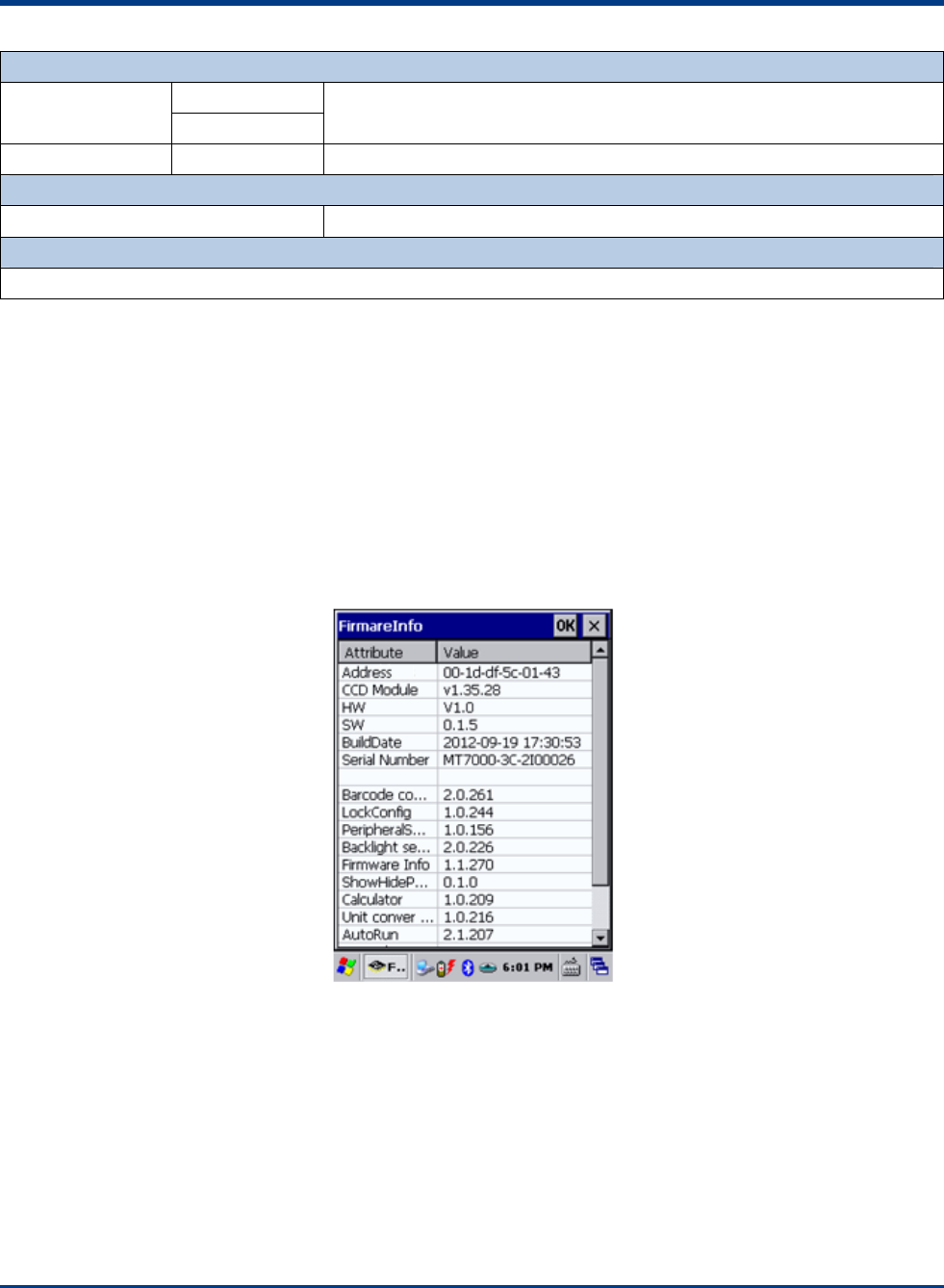
Software Version
Firmware information query tool can detect and display terminal software and hardware version information and helpful
future updates or maintenance.
The firmware information query tool can detect the information:
A. To determine the operation system version.
B. To determine the firmware version.
C. To determine the system configuration, production date and other information.
D. To determine the version of WIFI module, and WIFI MAC addresses.
E. To determine the type and version of barcode engine.
Tap “Start”→“Settings”→“Control Panel”→double clicks “Firmware Information”.
Figure 1.1: Firmware Information
3
Service Information
Newland China
Phone +86-400-608-0591
Email sales@nlscan.com
Newland Europe
Phone +31(0)-345-870-033
Email Info@newland-id.com
Newland Taiwan
Phone +886-2-7731-5388
Email Info@newland-id.com.tw
Newland North America
Phone +1-510-490-3888
Email Info@newlandna.com
4
Chapter 2 Getting Started
Introduction
This chapter lists the parts and accessories for the MT70 Series and explains how to install and charge the batteries, and
power on the MT70 Series for the first time.
Unpacking
Carefully remove all protective material from the pack.
Verify that you received the following:
MT70 Portable (Barcode) Data Collector
USB cable
AC adaptor
Li-Polymer battery
Tethered stylus
Hand strap
Quick Start Guide
Getting Started
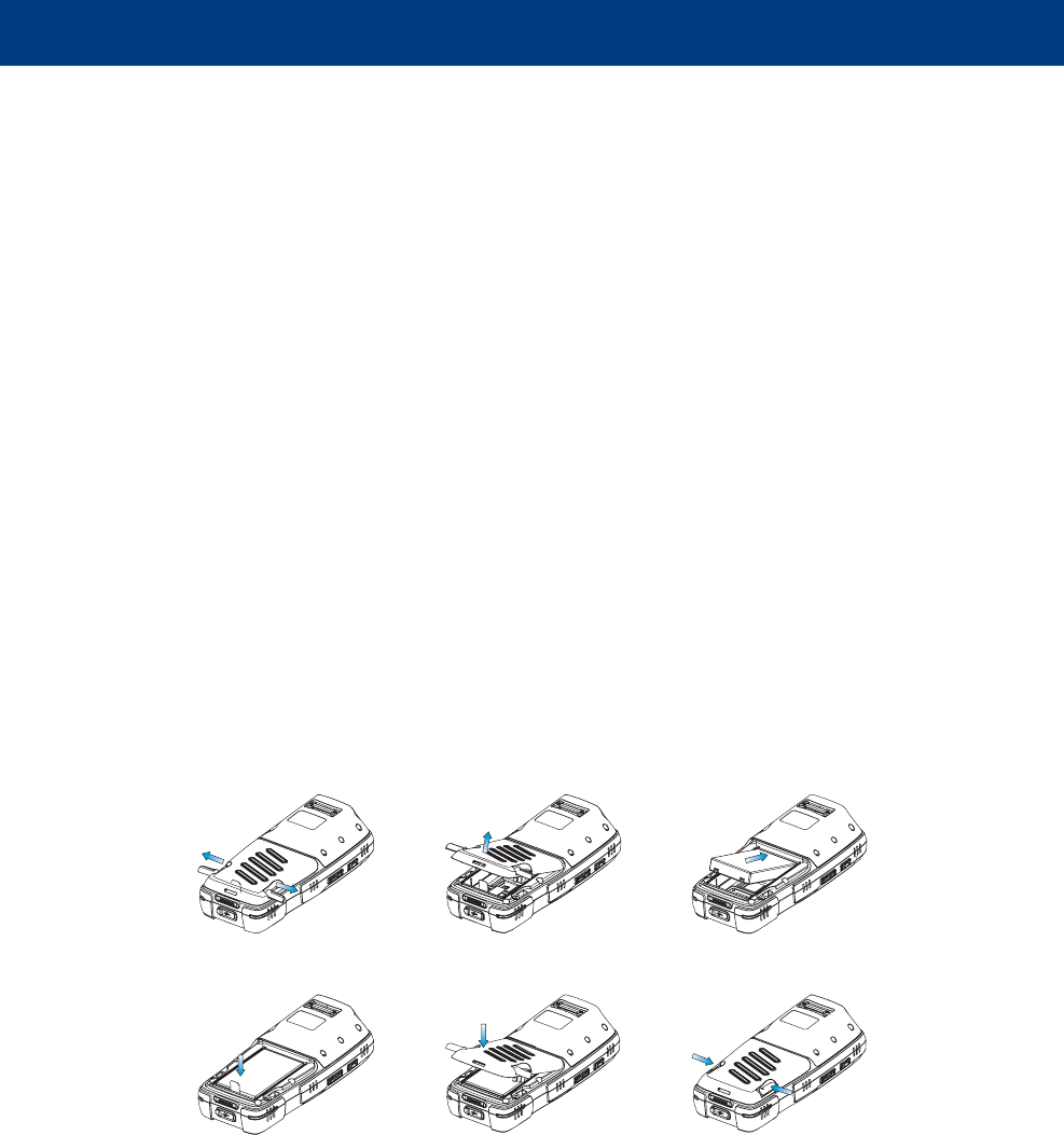
Installing the Main Battery
123
45 6
1. Figure 1 indicates the direction to unlock thelatch.
2. Figure 2 indicates the direction to take out the battery cover.
3. Follow the instructions of figure 3 and 4 to insert the battery.
4. Follow the instructions of figure 5 to close down the battery cover.
5. Push the latch to the lock position.
5
Charging the Battery
There are two ways to charge the battery:
Charge the terminal battery via USB connection to PC. Charging time: around 8-10 hours.
Charge the terminal battery via AC adaptor. Charging time: around 4 hours.
Charge the terminal battery at least 8 hours before its first use.
Charging indication: Charging: red LED; Fully Charged: green LED.
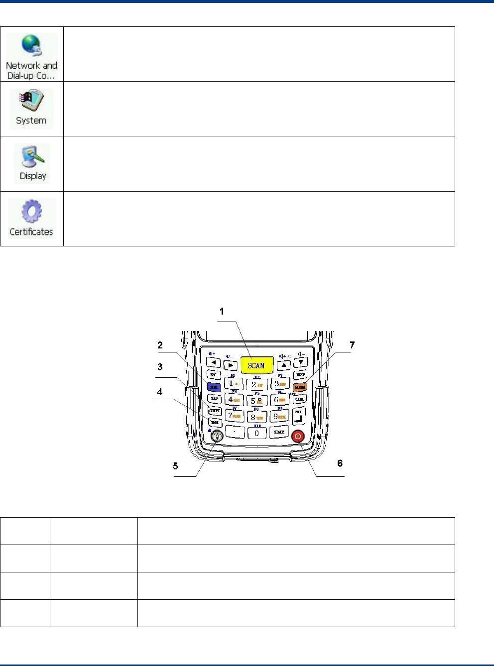
Keypads
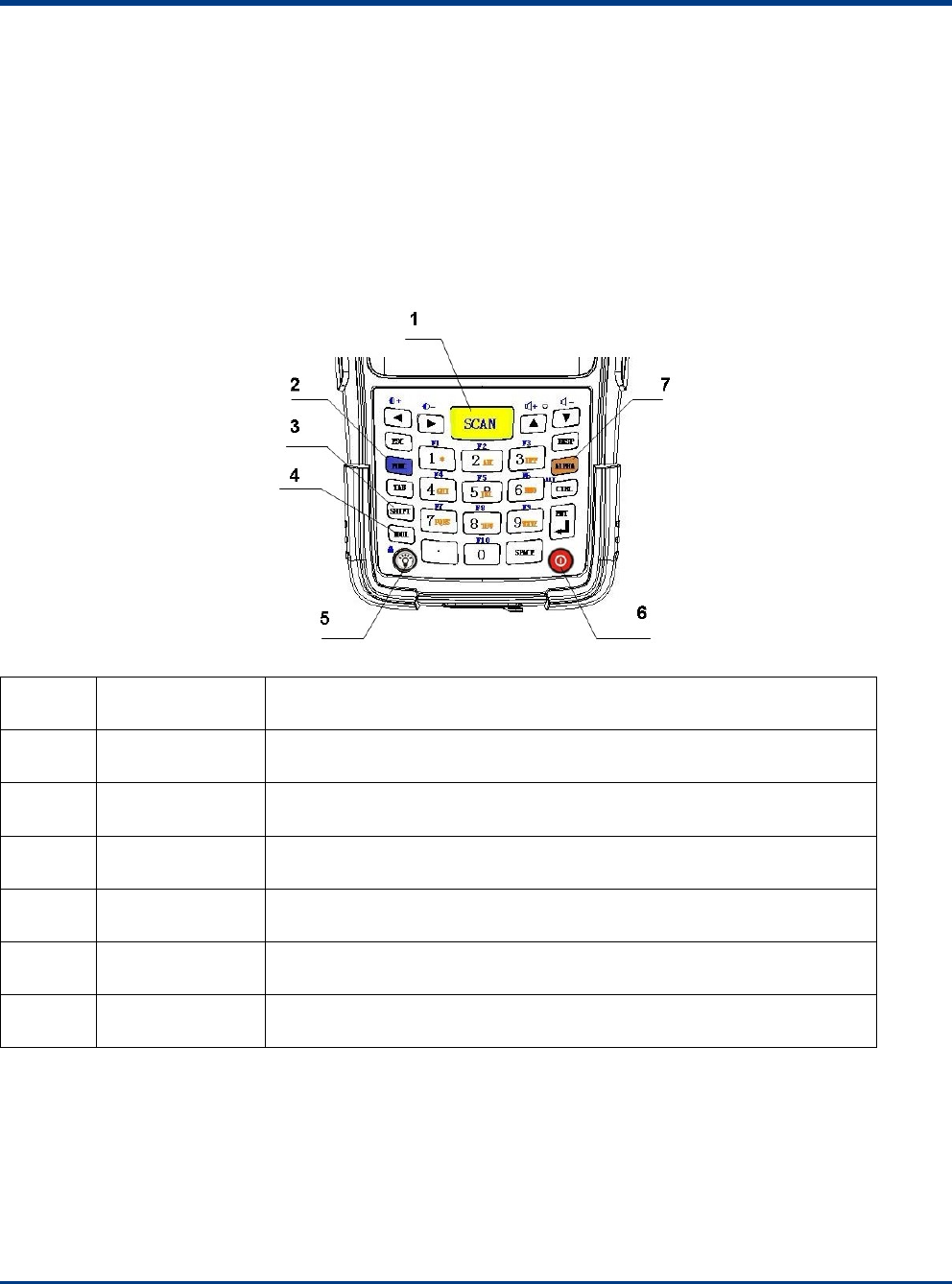
1 SCAN key Barcode reading button.
2 FUNC key User defined application function keys.
3 SHIFT key To switching upper or lower case letters.
4 TOOL key Pop-up shortcut menu, or perform shortcuts.
5 Backlight key Open or close screen backlight
6 Power key To power on, sleep or wake up the terminal.
7 ALPHA key Alpha or numeric input switching.
Power On, Suspend and Wake Up
Power On:
Long press the power button for 2-3 seconds to start the terminal.
Suspend:
6
During terminal in power on status, long press the power button for 2 seconds to turn terminal into suspend mode
immediately.
Terminal no operation in a period of time will go into suspend mode, when you turn on the auto suspend function.
The timer for automatically into suspend mode can be set by:
Tap “Start”→“Settings”→“Control Panel”→double clicks “Power”→“schemes”.
Wake Up:
During terminal in suspended status, press power button to wake up the terminal.
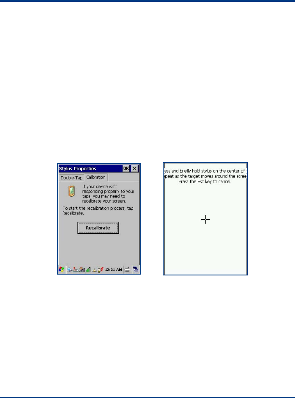
Calibrating the Screen
The touch screen calibration tool is for setting accuracy of the touch screen.
Tap “Start”→“Settings”→“Control Panel”→ double clicks “Stylus”→”Calibration”.
Click “Recalibrate” button then the screen becomes as shown in Figure 2.2.Carefully press and briefly hold the tip of stylus
on the center of each target that appears on the screen. Repeat as the target moves around the screen then tap the
screen to continue.
Figure 2.1: Calibration Figure 2.2: Recalibrate
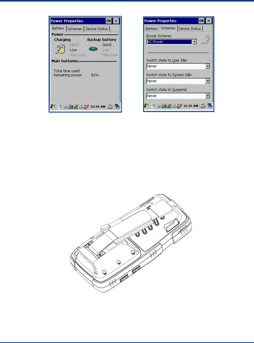
Checking Battery Statues
To check the charge status of the main battery in the terminal.
Tap “Start”→“Settings”→”System”→double clicks “Power”.
7
Figure 2.3: Power Properties Figure 2.4: Power Properties - Schemes
Power schemes has four status; “Running”, “User Idle”, “System Idle” and “Suspend”:
When user operates on the keypad or taps the touch screen, system is in the running state.
In running state, within the time set in the operating conditions no any operation, system turn to the user idle state.
In user idle state, within the time set in the operating conditions no any operation, system turn to the system idle state.
In system idle state, within the time set in the operating conditions no any operation, system turn to suspend state.
Adjusting the Hand Strip
The MT70 Series handstrap is attached to the bottom of the terminal. Adjust the hand strap to increase comfort when
holding the terminal for extended periods of time.
8
Chapter 3 Using the MT70 Series
Introduction
This chapter provides the detailed instructions for using and setting the MT70 Series.
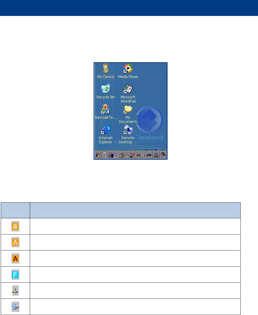
Figure 3.1: Desktop Icons
Status Icons
The status bar at the bottom of the screen can contain the status icons listed in Table 3.1
Table 3.1 Status Icons.
Icon Description
Lowercase input. In state of digital input, pressed ALPHA key.
Uppercase input. In lowercase input state, pressed SHIFT key.
Uppercase lock. In lowercase input state, double pressed SHIFT key.
FUNC key pressed.
IP information.
USB connection status.
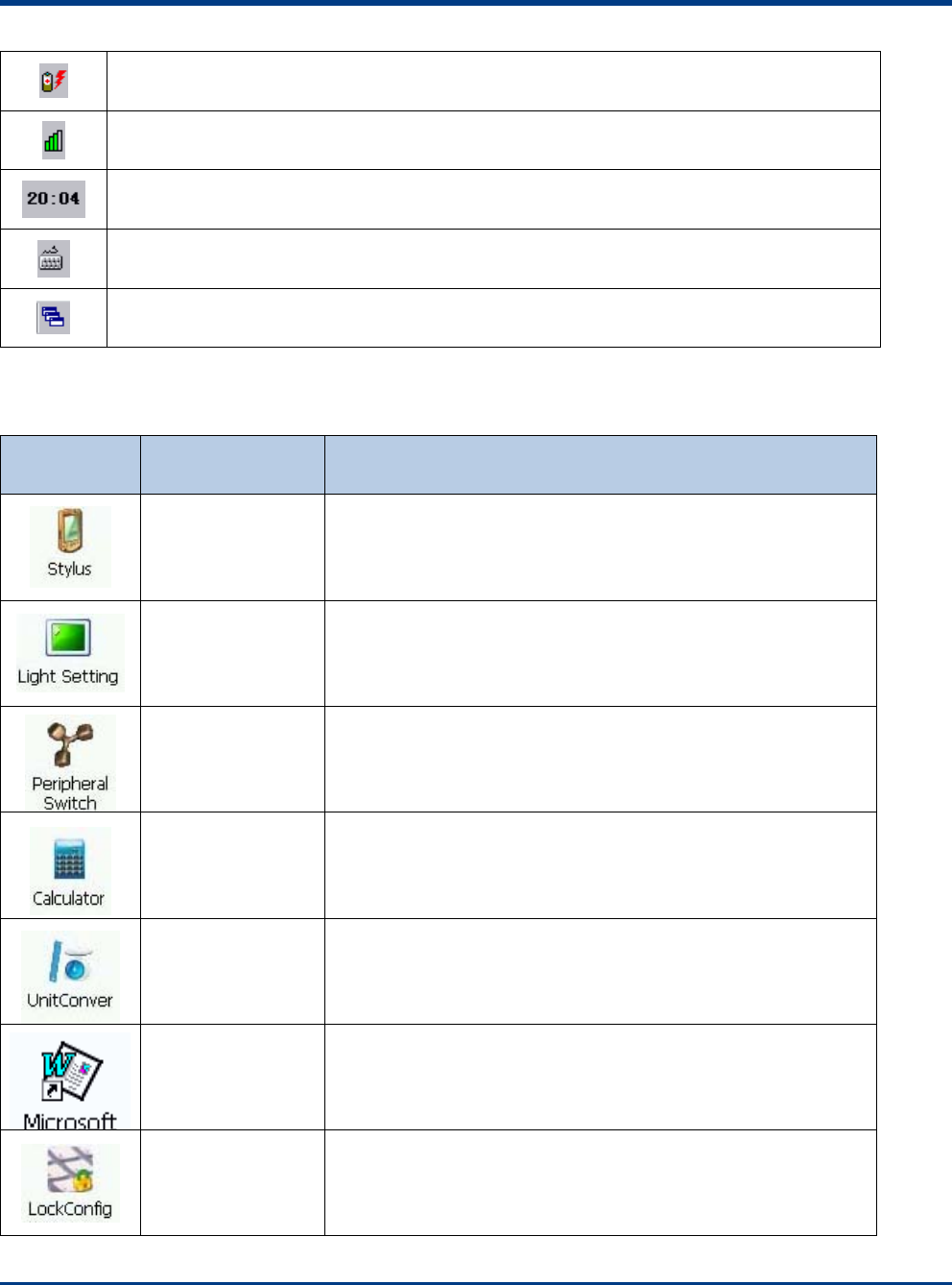
9
Indicates battery charging.
WiFi signal status.
Displays current time.
Keyboard panel.
Background running program selection window.
Programs Icon
Table 3.2 Software utilities icons.
Icon Program Name Description
Stylus For the touch screen calibration settings.
Light Setting For the screen and keyboard backlight settings.
Peripheral Switch Used to offer power control function for peripheral module.
Calculator For numeric calculation.
UnitConver Unit conversion tool.
Microsoft WordPad Mocrosoft WordPad text editing tool.
LockConfig To keyboard and touch screen lock or unlock tool.
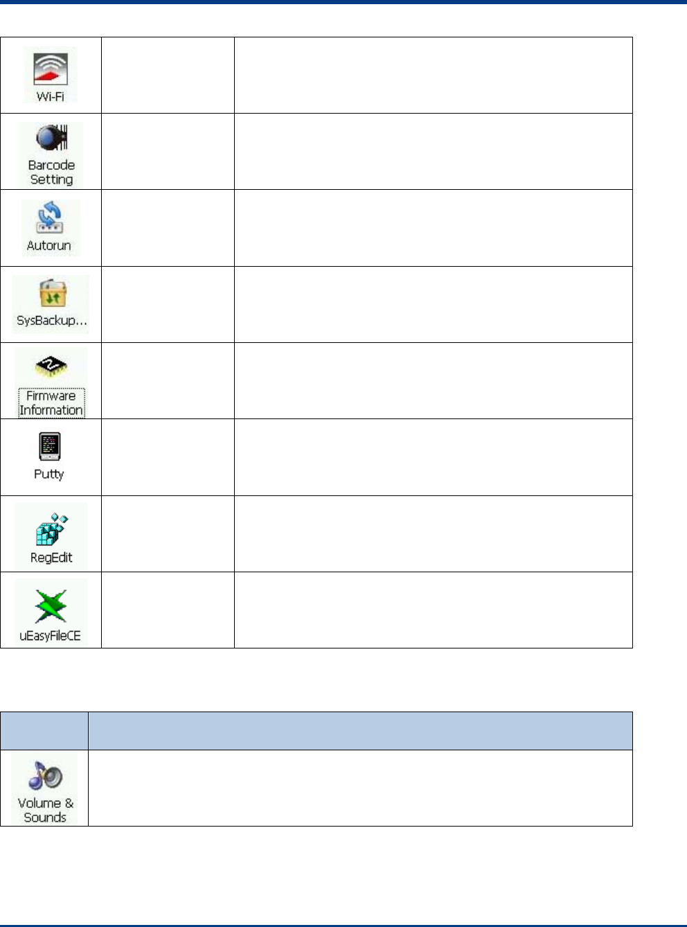
10
Wi-Fi WiFi communication management and configuration tool.
Barcode Setting Barcode engine configuration tool.
Autorun Setting the programs and parameters which need to boot automatically.
SysBackupRestore Backup/Restore system registry, configuration and data in storage
memory.
Firmware Information For checking the system firmware information and version.
Putty For Telnet terminal emulation tool.
RegEdit System registry editing tool.
uEasyFileCE Bluetooth file transfer utility.
Setting Programs Icon
Icon Description
System volume adjuster.
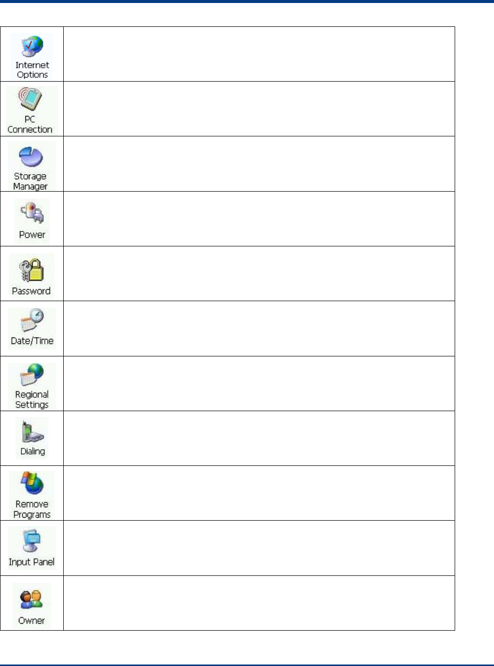
11
Internet options setting tool.
Enable/Disable connects with host PC.
Memory storage management and configuration.
Battery and devices power status and system power schemes settings.
Password attributes (power on password and screen saver password) settings.
System date, time and time zone settings.
Region, language and input method settings.
Dialing configuration.
To remove programs that installed on the terminal.
Input panel setting.
Owner properties setting.
12
Network connects configuration.
System information.
Screen display interface and backlight configuration.
View the information about certificates installed on the terminal.
Keypads
1 SCAN key Barcode reading button.
2 FUNC key User defined application function keys.
3 SHIFT key To switching upper or lower case letters.
4 TOOL key Pop-up shortcut menu, or perform shortcuts.

13
5 Backlight key Open or close screen backlight
6 Power key To power on, sleep or wake up the terminal.
7 ALPHA key Alpha or numeric input switching.
Numeric Keypad input mode
On ALPHA key locked state On ALPHA + SHIFT keylocked state
Numeric
Key 1st 2nd 3rd 4th 1st 2nd 3rd 4th
1 *
2 a b c A B C
3 d e f D E F
4 g h i G H I
5 j k l J K L
6 m n o M N O
7 p q r s P Q R S
8 t u v T U V
9 w x y Z W X Y Z
Function Keys Introduction
FUNN key + Backlight key: Lock/ Unlock function.
This locking function only work for one time then turn to unlock state automatically.
ALPHA and FUNC key is an independent processing, operation will not overwrite each other.
The SHIFT key is only works on the ALPHA key be pressed.
ALPHA and SHIFT key combination types:
z The keyboard is in lowercase input state when the SHIFT key is not pressed. The status bar display lowercase
icon.
z The SHIFT key pressed once. Status bar display uppercase icon and turn back to lowercase icon after pressed any
alpha key. If the pressed key is not an alpha key, to give up the SHIFT operation back to lowercase state.
z Double pressed the SHIFT key (within 0.5 seconds) turn to uppercase input state, statues bar display uppercase
icon. Pressed the SHIFT key again would turn back to lowercase state.
Long pressed or double pressed the TOOL key could popup the shortcut window.
Pressed the TOOL key + a number key, run the corresponding program.
Stylus
Use the MT70 Series stylus to select items and enter information. The stylus functions as a mouse.
14
Tap : Touch the screen once with the stylus to select the menu item.
Tap and Hold : Tap and hold the stylus on an item to see a list of actions available for that item.
Drag : Hold the stylus on the screen and drag across the screen to select text. Drag in a list to select multiple
items.
CAUTION: To prevent damage to the screen, do not use any device other than the Newland provided stylus.
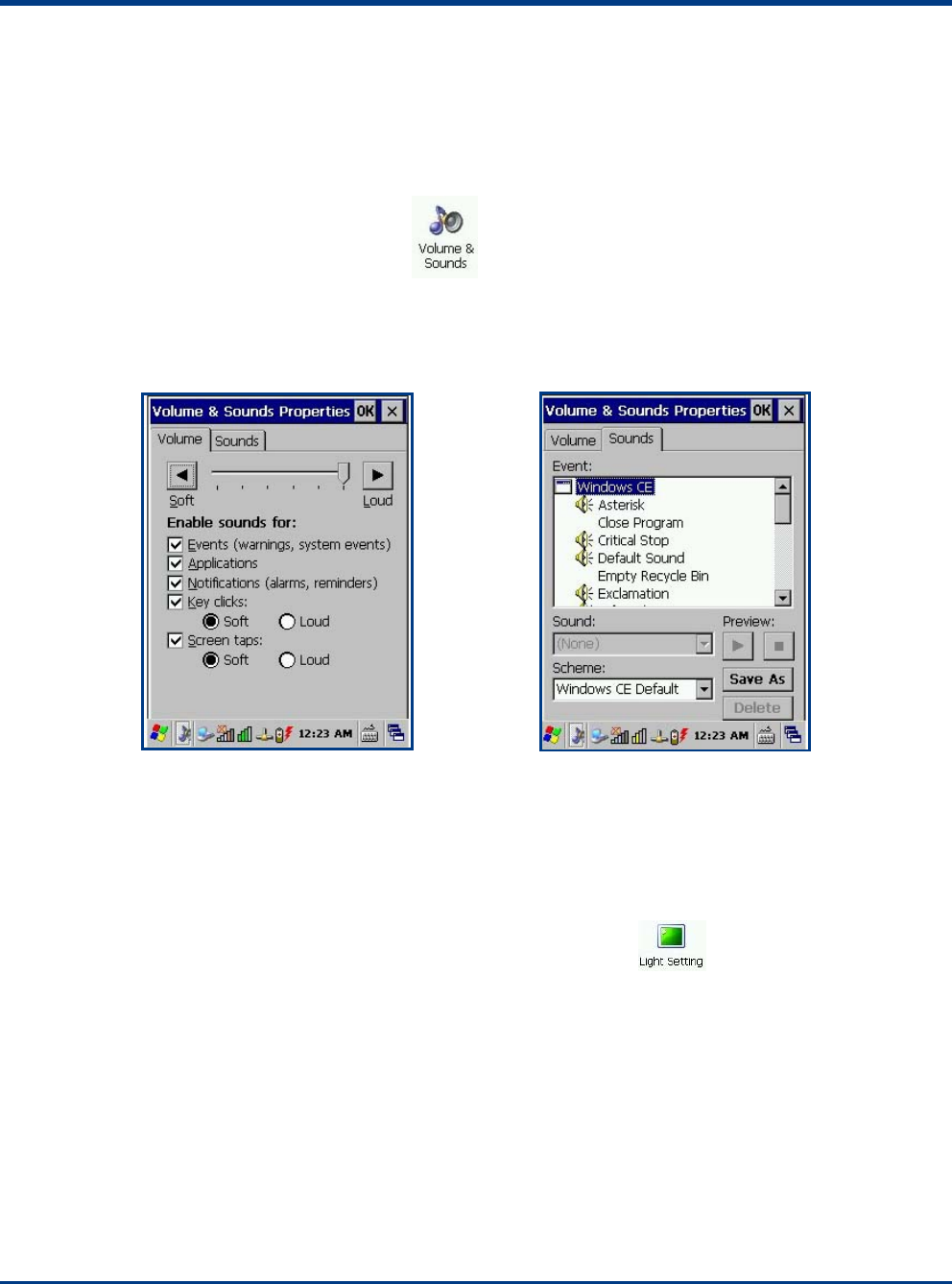
Adjust Volume
Adjust the system volume using the tool program in control panel
Tap “Start”→“Setting”→“ControlPanel”→double click “Volume & Sounds”.
Click and move the slider to adjust the volume on "Volume and Sounds" dialog box.
Figure 3.2: Volume Figure 3.3: Sounds
Change Backlight Settings
Use Light Setting program you can set the screen and keyboard backlight. Screen backlight has normal mode and
low-power mode. Use this tool can also be set according to the different needs of the backlight brightness and auto-off
timer.
Tap “Start”→“Settings”→“ControlPanel”→double click “Light Setting” as icon.
Screen backlight setting:
z Normal Mode:
The backlight brightness can be set from 0-10 grade. You can drag the selected bar or click the up or down arrow
to set the grade. Touch the screen or press any key will activate the backlight.
z Low-power Mode:
Low-power mode backlight brightness level can be set from 0 to the grade of normal mode.
z Switch Timer
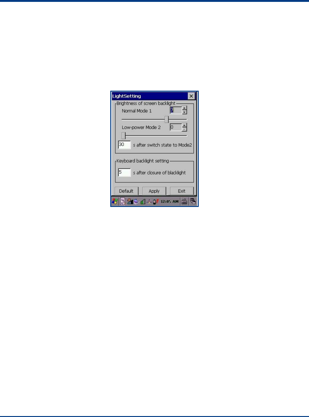
15
Set after how many seconds if there is no touch the screen or keyboard press, the backlight automatically turn into
low-power mode.
Keyboard backlight setting:
Set after how many seconds if there is no keyboard press, the backlight turn off automatically
When you no press any key in a period of time, the keyboard backlight will turn off automatically.
Figure 3.6: Backlight setting
Memory storage management
“Storage Manager” is a tool for manage the memory.
Actions mode:
Format :Format the selected memory, the data in memory will be destroyed after memory formatted.
Dismount :Dismount the selected memory.
New Partitions :Create a new partition in selected memory.
Delete Partitions :Delete a exist partition in selected memory.
Caution: The memory configuration changes will destroy all the data in memory, please contact with
technical staff before change.
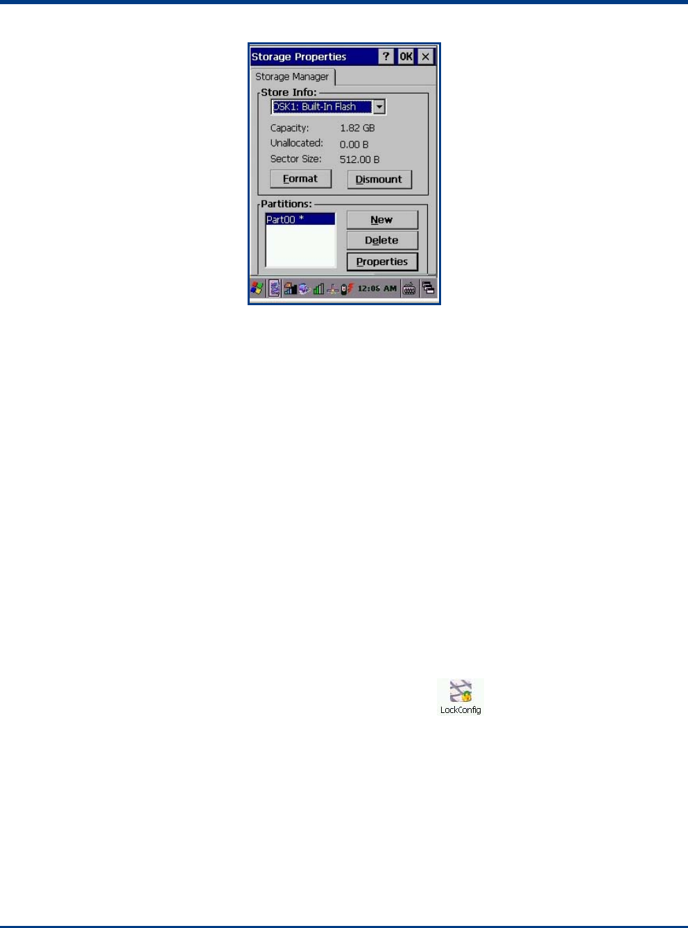
16
Figure 3.7: Memory Configuration
Resetting the MT70
Warm reset:
Press the reset button to warm reset the terminal. It will take around 6-10 seconds to restart the system. User data in
memory will not to destroy.
Cold reset:
Cold reset the terminal by hold the power key and pressed reset button and release the power key when screen redisplay.
It will take around 16-20 seconds system reloading and start again.
Terminal will restart in factory default setting. User data in memory will destroy. You can use backup/restore tool to process
your data.
Notice:The battery cover must be closed before execute reset function, otherwise the terminal will turn into
suspend mode.
Locking theMT70
Use the device lock feature to prevent use of the device.
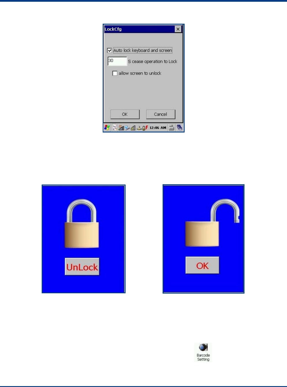
Tap“Start”→“Settings”→“ControlPanel”→double click “LockConfig” icon.
17
图3.8: Lock configuration
Below status you can lock the keyboard and touch screen.
A. Terminal not operation in a period of time or by FUNC key + backlight button.
B. Pressed screen unlock button to unlock your terminal.
Figure 3.9: Lock state Figure 3.10: Unlock state
Barcode Settings
Barcode engine parameter configuration
Tap“Start”→“Settings”→“ControlPanel”→double click “Barcode Settings” icon.
18
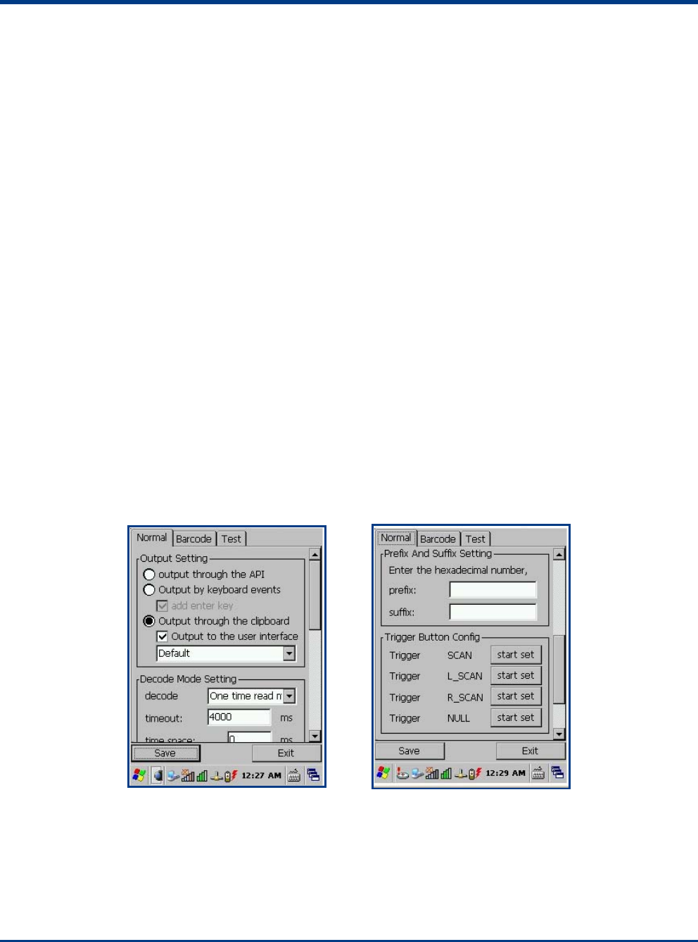
Barcode Setting program include Normal setting, Barcode setting and Test three select pages.
A. Normal Setting:
Output Setting:
z Output through the API : Use program API libraries control to get the barcode data.
z Output by keyboard events : Output the barcode data to keyboard buffer to simulate keyboard input.
z Output through the clipboard : Output the barcode data to clipboard.
Decode Mode Setting:
z Decode Mode:
¾ One time read mode : Press key start to scanning barcode, and released key to stop scanning.
¾ Start scan by key press : Press key start to scanning barcode until read success or time out to stop
scanning.
¾ Continue read mode : Continue scanning barcode until change the reading mode.
¾ Read control by API : Start or stop scanning barcode by API software control.
z Time Out:
Setting the timer of time out for scanning barcode, default value is 4000ms.
Prefix and Suffix Setting:
z Provided the barcode reading result plus prefix or suffix function.
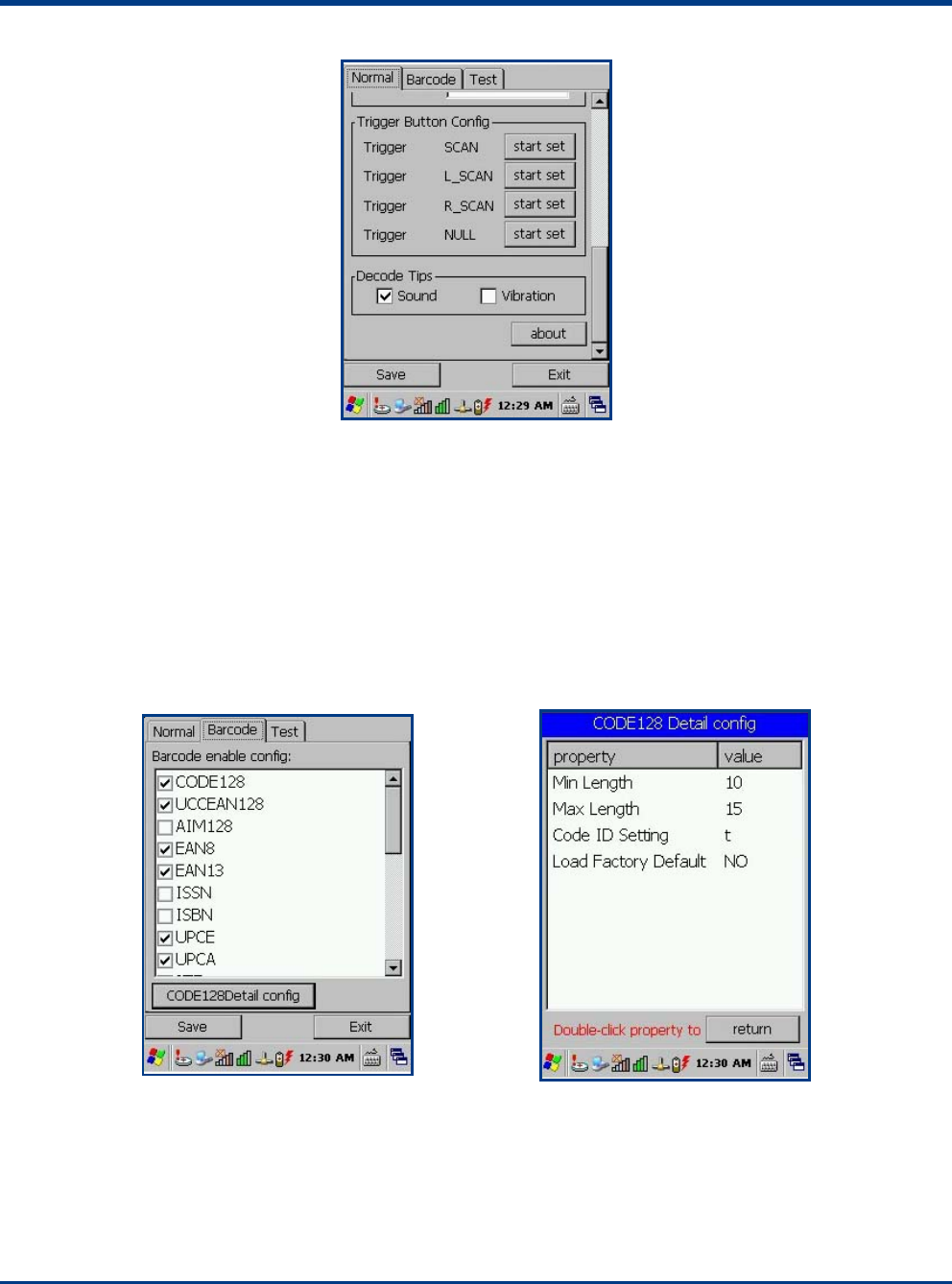
Trigger button Config:
z Enable/Disable the trigger key.
z Press “start set” button to disable the trigger key or press a trigger key to set a new one.
Decode Tips:
z Select the indicate method for reading success.
Figure 3.11: Normal setting 1 Figure 3.12: Normal setting 2
19
Figure 3.13: Norma setting 3
B. Barcode Setting:
Depend on the mode of your terminal, barcode setting page will display difference setting item.
1D Barcode configuration:(Laser/CCD)
z Each type of 1D barcode enables or disables.
z Each type of 1D barcode detail configuration.
2D Barcode configuration:(CMOS)
z Each type of 2D barcode enables or disables.
z Each type of 2D barcode detail configuration.
Figure 3.14: Barcode configuration Figure 3.15: Barcode detail setting
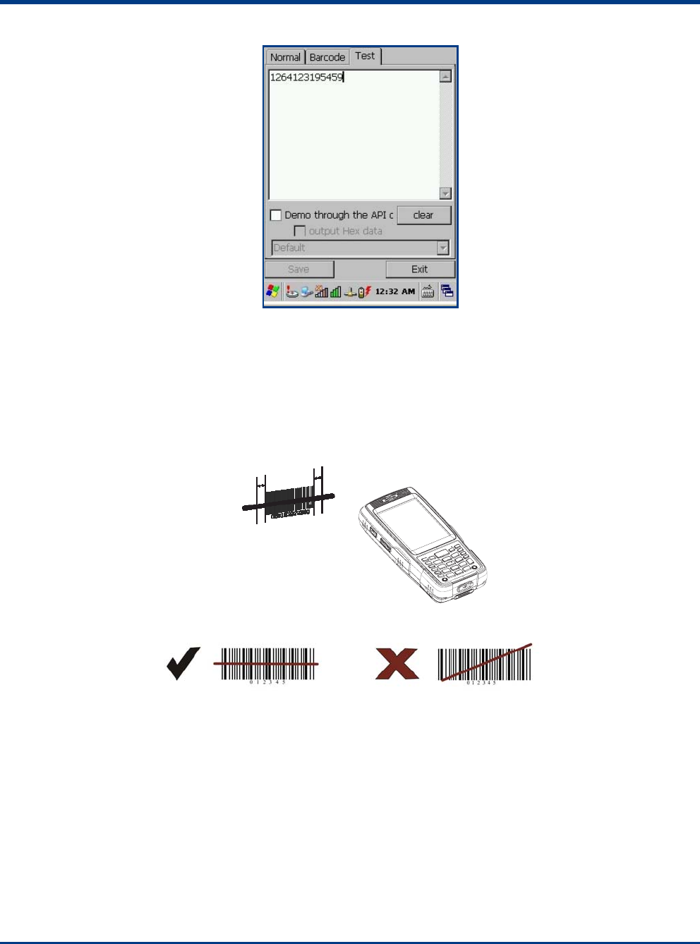
C. Barcode Testing
Tap “Test” selection to display the below figure to test the barcode reading.
20
Figure 3.16: Barcode test
Reading 1D barcode
Adjust the terminal barcode reading angle or the distance between barcode with terminal. Let the width of the scan line
appropriately larger than the width of the barcode (about 4mm), in order to get the best reading.
Right and wrong way of reading:
Reading 2D barcode
The best reading distance and angle:
A. Adjust the terminal focus lights aiming to the center of 2D barcode.
B. Adjust the reading distance between the terminal with barcode around 5-20 cm.
C. Adjust the reading angle:
z The relative pitch angle (the α) with barcode and terminal is less than 45 degrees (0 is the best)
z The relative skew angle (the γ) with barcode and terminal is less than 45 degrees (5~20 is the best)
z The relative roll angle (the β) with barcode and terminal can be any angles (0~360 degrees).
21
Chapter 4 Using WiFi Communication
Note: WiFi communication is an optional feature.
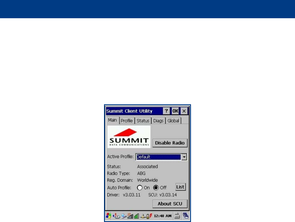
A. Main Window
TheMainwindowprovidesanoverviewofthecurrentwirelessnetworkconnectionconfiguration(ActiveProfile)
Thefollowingimage(inFigure5.1)istheSCUMainwindowsforWindowsCE.
Figure5.1:SCUMainWindow
EnableRadio/DisableRadio
Whentheradioisenabled,selectthisbutton(whichdisplaysDisableRadio)todisableit.Whentheradiois
disabled,selectthesamebutton(whichnowdisplaysEnableRadio)toenableit.Whendisabled,theradiodoes
notattempttomakeaconnectiontoanaccesspoint.
ActiveProfile
Todisplaysthenameoftheactiveprofile.Usethedrop‐downmenutoselectadifferentprofile.
Note:IfThirdPartyConfigisselected(andafterthedevicegoesthroughapowercycle),WZC(WindowsZero
Configuration)oranotherapplicationisusedtoconfiguretheSSID,AuthType,EAPType,andEncryption
settings.
Status
ToindicatesthecurrentstatusoftheSummitradio.Connectionstatusesinclude:
Down ‐ TheradioisnotrecognizedbySummitsoftwareandthereforeisnotassociatedand
norauthenticated.
22
Disabled ‐Theradioisdisabled.Toenabletheradio,tapEnableRadiolocatedontheSCUMain
window.Whentheradioisdisabled,itdoesnotattempttomakeaconnectiontoan
accesspoint.
NotAssociated‐Theradiohasnotestablishedaconnectiontoanaccesspoint.
Associated ‐ Theradiohasestablishedaconnectiontoanaccesspoint.
IftheradioEncryptiontypeissettoWEPorapre‐sharedkey(WPA‐PSKorWPA2‐PSK),itshouldnowbecapableofobtaininganIP
address(eitherstaticallyassignedorthroughDHCP)andpassingtraffic.
IftheradioEncryptiontyperequiresEAPauthenticationthenanEAPTypemustbeproperlyconfiguredinorderforthedeviceto
obtainanIPaddressandbecapableofpassingtraffic.
<EAPtype>Authenticated‐TheradiohasestablishedaconnectiontoanaccesspointandhascompletedEAPauthentication
successfully.
RadioType
Indicatesthetypeofradioinstalledinthedevice.Forexample:
BG ‐ IndicatesaSummit802.11gradiowhichsupports802.11band802.11g.
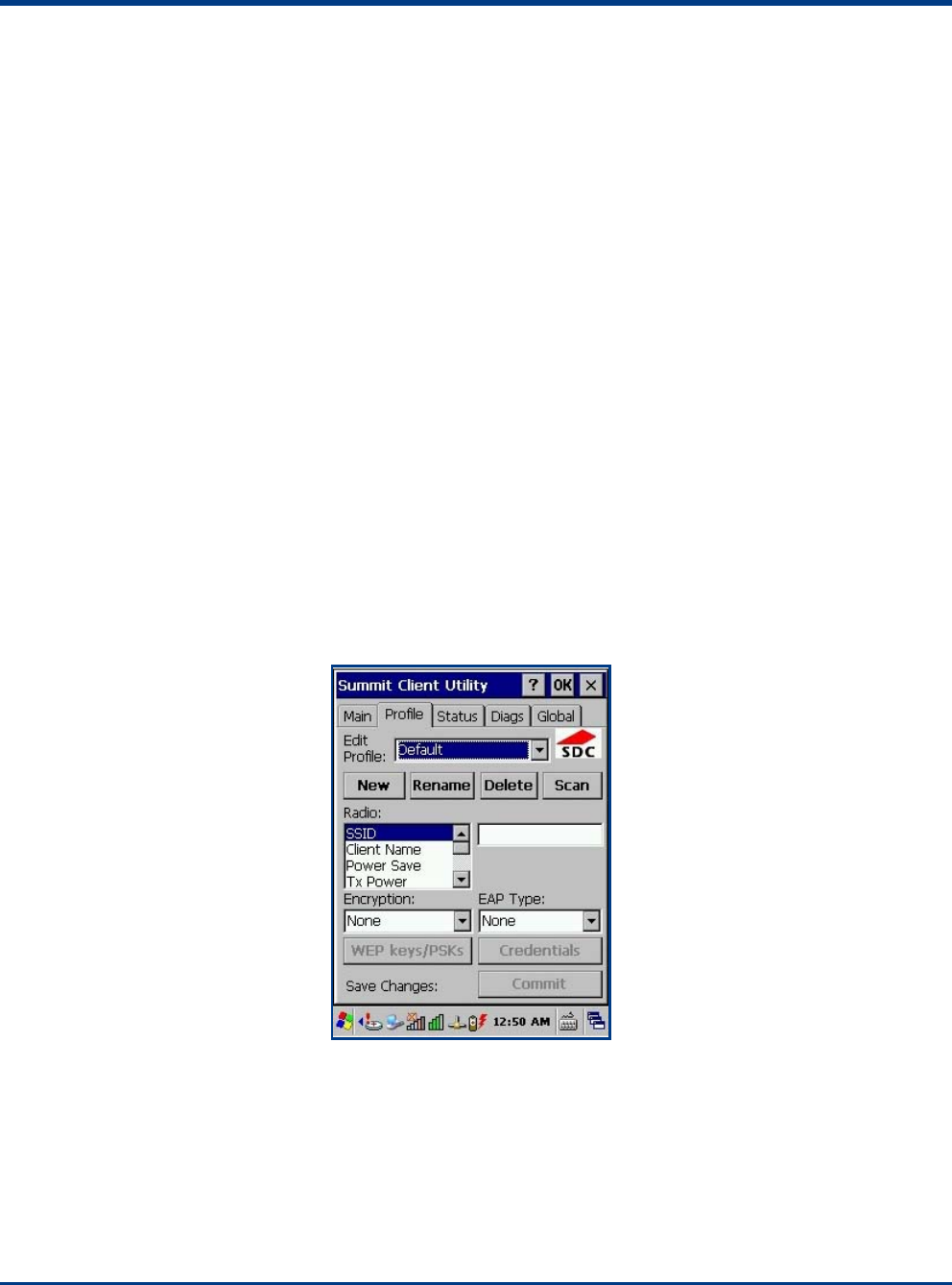
B. Profile Window
Profilesettingsareradioandsecuritysettingsthatarestoredforeachconfigurationprofile.Whenaprofileisselectedastheactive
profileontheMainwindow,thesettingsforthatprofilebecomeactive.
Notes:WhentheThirdPartyConfigprofileisselected,apowercyclemustbeperformed.
Thefollowingimage(inFigure5.2)istheSCUProfilewindowsforWindowsCE
Figure5.2:SCUProfileWindow
ProfilechangesarenotsavedtotheprofileuntilyoutapCommit.
UsingScantoCreateaProfile
WhenyoutapScanontheProfilewindow,SCUdisplaysalistofthatarebroadcastingtheirSSIDs.Figure5.3belowisanexampleof
aScanwindow.
23
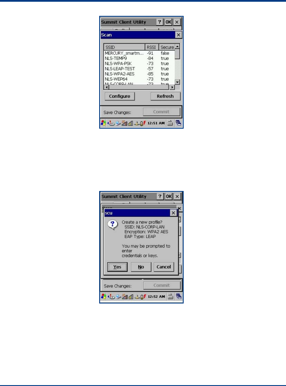
Figure5.3:ScanWindow
EachrowshowsanAP'sSSID,itsreceivedsignalstrengthindication(RSSI),andwhetherornotdataencryptionisinuse(trueorfalse).
Youcansortthelistbytappingonthecolumnheaders.IfthescanfindsmorethanoneAPwiththesameSSID,thelistdisplaystheAP
withthestrongestRSSIandtheleastsecurity.Everyfiveseconds,theScanwindowupdatestheRSSIvalueforeachoftheAPsinthelist.
ToscanfornewAPsandviewanupdatedlist,tapRefresh.
IfyouareauthorizedasanadministratorinSCU,youcancreateaprofileforanySSIDinthelist.Tocreateaprofile,double‐taptherow
fortheSSID;ortaptherowandthentapConfigure
Figure5.4:ScanWindow
IfyoutapYesonthedialogbox,thenSCUcreatesaprofileforthatSSID,withtheprofilenamebeingthesameastheSSID(orthe
SSIDwithasuffixsuchas"_1"ifaprofilewiththeSSIDasitsnameexistsalready).IftheAPisusingWEP,thenSCUopensadialog
boxinwhichyoucanspecifyWEPkeys.IftheAPisusingEAP,thenSCUopensadialogboxinwhichyoucanspecifylogin
credentialsfortheEAPtype(whichSCUassumesisLEAP).Afteryouenterinformationonadialogbox,youreturntotheSCUProfile
window,whereyoucanviewandeditprofilesettings.Ifyoumakeanychanges,thenyoumusttapCommittosavethechanges.
C. Status Window
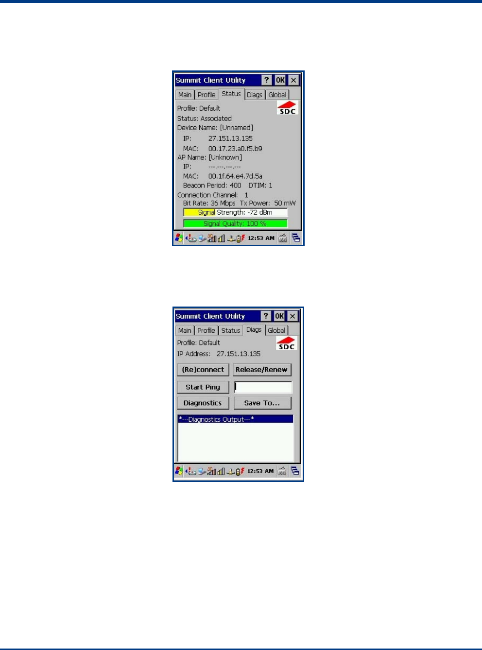
24
TheStatuswindowprovidesstatusinformationontheradioconnectionbetweentheclientdeviceandtheaccesspointtowhichit's
associated.
ThefollowingimageistheSCUStatuswindowsforWindowsCE.
Figure5.5:StatusWindow
D. Diags Windows
TheDiagswindowsenablesyoutotroubleshootconnectionissueswithSCU.ThefollowingimageistheSCUDiagswindowsfor
WindowsCE.
Figure5.6:Diagswindow
(Re)connect
Initiateareconnectoftheradio:Disableandenabletheradio,apply(orreapply)thecurrentprofile,attempttoassociatetothe
wirelessLAN,andattempttoauthenticatetothewirelessLAN.
Release/Renew
ObtainanewIPaddressthroughDHCPrelease/renew.
StartPing/StopPing
Startacontinuouspingtotheaddressintheeditboxnexttothebutton.Oncethebuttonistapped,itsnameandfunctionchanges
toStopPing.PingscontinueuntilyoutapStopPing,movetoadifferentSCUwindow(otherthanDiagsorStatus),exitSCU,or
25
removetheradio.
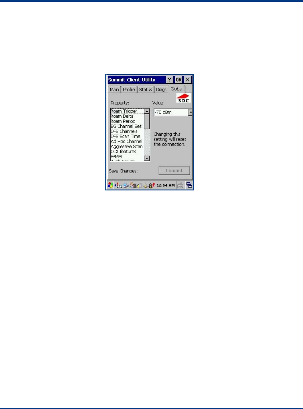
E. Global Window
GlobalsettingsincluderadioandsecuritysettingsthatapplytoallprofilesandsettingsthatapplytoSCUitself.Anadministrator
candefineandchangemostglobalsettingsontheGlobalwindowinSCU.
ThefollowingimageistheSCUGlobalwindowsforWindowsCE
Figure5.7:Globalwindow
26
Chapter 5 Accessories
Battery
Terminal battery capacity too low will cause the terminal malfunction. Please charge the battery at less than 8 hours for
sure the main battery and backup battery capacity was in full charge states.
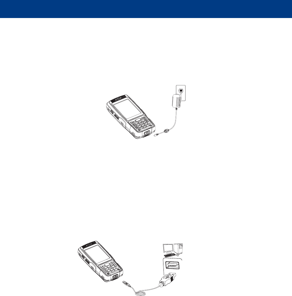
Charging
Use AC adaptor charging
LED charging indicator
Red light long bright : During charge.
Green light long bright : Charge complete.
LED indicator for Scanning/Decoding/Communication
Red light bright : During scan barcode.
Green light bright : Success decoded barcode.
Blue light flash : Communication module (WIF)during communication.
Connect Host PC via USB cable
1. Open the USB port cover which is located in bottom of MT70.
2. Plug in USB cable connector to MT70 USB port and the other sides of cable connect to host PC.
Notice: Please make sure the host PC already installed Microsoft ActiveSync before connection.

27
Chapter 6 Maintenance& Troubleshooting
Introduction
This chapter includes considerations on operation and battery charging, and providestroubleshooting solutions for
potential problems during the terminal operation.
Considerations on using MT70
Disassembly and modification
Please do not attempt to disassemble or modify the terminal, if cause the damage to the terminal, Newland does not
assume warranty responsibility.
Connect power source
Please use the terminal original power adapter otherwise there is a risk of damage to the terminal.
Abnormal situation
Leave far away from fire source during battery charging. Turn off the power when you found abnormal odor, overheating or
smoke situation and contact Newland service center, there is a risk of fire if continue charge.
Drop Damage
If the terminal caused the damage because drop down. Please turn off the power and contact with Newland service center
for help.
LCD Display
Do not stress or impact LCD screen, it may cause the broken glass of the LCD panel. If the glass of the LCD panel is
broken, please do not touch the liquid, for fear to cause skin burns or infection.
Stacking heavy objects
Do not place heavy objects stacked on the terminal in order to avoid heavy objects lose balance and fall over cause injury.
Placed location
Do not placed the terminal in unstable, too moisture or dust places. It may cause to fire or electric shock, and also do not
placed in direct sunlight for a long time.
Use occasion
Due to the terminal wireless module electromagnetic waves radiation will affect some instruments, so in the particular
occasion that prohibited to use the wireless devices, such as aircraft, gas stations. Please do not use the wireless terminal
in these occasions.

28
Caution
If the terminal lost power or abnormal cause can not boot up, try a hardware reset to start it, the method is to press
the reset button with needles. The location of reset button, please refer to the related chapter.
Please do not throw or drop the terminal to avoid the LCD screen is damaged or cause the program interrupt
execution to make the memory data loss, or other consequences of affecting the normal operation.
Clean the reading window periodically. Do not touch the transparent glass of the scanning window to avoid scratch or
stain glass affecting reading performance.
Please do not use sharp objects to touch the screen, it may cause the screen is damaged or the internal short circuit.
Please use a soft and dry cloth to wipe the terminal, and do not use a damp cloth, benzene, thinner or other volatile
chemicals to avoid the terminal keyboard and shell variant of aging.
Do not let the terminal face down in order to avoid the keyboard disoperation.
The environment temperature great change will lead to the terminal surface condensation, please dry the terminal
before use.
Adapter shall be installed near the equipment and shall be easily accessible. The plug considered as disconnect
device of adapter. The power adapter shall be considered as safety approval by CE(Adapter AC input: 100-240V~,
50/60Hz 0.4A; Output: 5Vdc/1.5A
Manufacturer of Adapter: Guande Technology Co., Ltd. Model No.: KSAS0100500150D5)
The antenna(WIFI) is installed with 20 cm maintained between the antenna and users.
Extreme Temperature: -20~+45
Battery safety guidelines
Battery in fire will cause an explosion.
Battery can charge and discharge at least more than 500 times. Please renew the battery when the battery
noticeably in shorter battery life.
Using the battery only provided from Newland, and also use the power adapter only provided from Newland to
charge the battery.
Please unplugged the adapter when battery was fully charged, and do not continue to charge the battery. Since
overcharging may shorten battery life. A fully charged battery is left unused, the battery will gradually discharge. It will
not cause any abnormal states.
Do not use the damage or abnormal battery or adaptor already.
Please correctly collect and dispose of the battery and do not dispose the battery as general garbage.

29
Troubleshooting
Problem
Cause & Solution
Type Description
Keyboard
Keyboard malfunction or
wrong character display.
May be the keyboard components damage or cable loose contact between
with mainboard socket. Please contact Newland maintenance or after
service center.
Battery
Battery indicator doesn't light
when charging.
Check the adapter plugged in power outlet or contact with the terminal is well
or not.
Battery noticeably in short
battery life.
z Check the battery whether is fully charged or malfunction.
z Replace a battery if the battery is malfunction.
Battery is depleted. Replace the battery.
USB
USB cannot communication. z Make sure the communication cable is plugged in well.
z Make sure the connector or port whether is obstruction.
If there is no above situation, it may be the components failure, please
contact the maintenance or after service center.
LCD
Screen
Cannot see characters on
display.
z Check the terminal whether is powered on.
z Check the terminal whether is in suspended mode. Wake up the terminal
first if yes.
z Check the battery whether is in low states. Recharging the battery if yes.
z Check the battery whether is poor contact. Reload the battery if yes.
z Check the battery whether is depleted. Replace the battery if yes.
If there is no above situation, it may be the components failure, please
contact the maintenance or after service center.
System
Does not power on. z Battery is in too low states may cause cannot turn on. Charging the
battery over 8 hours then try again.
z Replaced a battery if the battery was damage.
If there is no above situation, it may be the components failure, please
contact the maintenance or after service center.
System crash. z Possible the user application to cause the terminal crashes, please check
your application whether is safe.
z May be the terminal accidental power down, please use the needles to
reset the terminal.
z If reset does not work, try use cold reset to reboot the system.

30
FCC Warning:
This equipment has been tested and found to comply with the limits for a Class B digital device, pursuant to part 15 of the FCC
Rules. These limits are designed to provide reasonable protection against harmful interference in a residential installation. This
equipment generates, uses and can radiate radio frequency energy and, if not installed and used in accordance with the
instructions, may cause harmful interference to radio communications. However, there is no guarantee that interference will not
occur in a particular installation. If this equipment does cause harmful interference to radio or television reception, which can be
determined by turning the equipment off and on, the user is encouraged to try to correct the interference by one or more of the
following measures:
• Reorient or relocate the receiving antenna.
• Increase the separation between the equipment and receiver.
• Connect the equipment into an outlet on a circuit different from that to which the receiver is connected.
• Consult the dealer or an experienced radio/TV technician for help.
Caution: Any changes or modifications to this device not explicitly approved by manufacturer could void your authority to
operate this equipment.
This device complies with part 15 of the FCC Rules. Operation is subject to the following two conditions: (1) This device may not
cause harmful interference, and (2) this device must accept any interference received, including interference that may cause
undesired operation.