Fujitsu Client Computing WB0010 T Series Tablet PC with WM3B2200BG and UGXZ5-102A User Manual T Series
Fujitsu Limited T Series Tablet PC with WM3B2200BG and UGXZ5-102A T Series
Contents
- 1. Manual Part 1
- 2. Manual Part 2
- 3. Manual Part 3
Manual Part 3

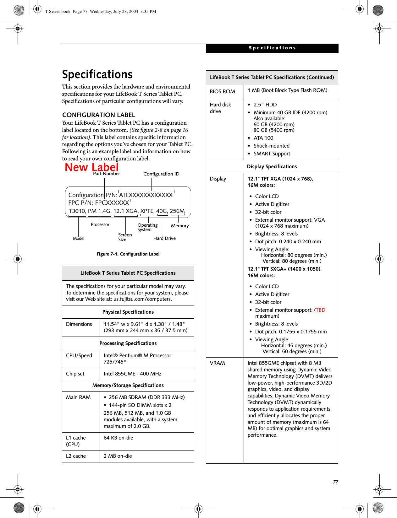


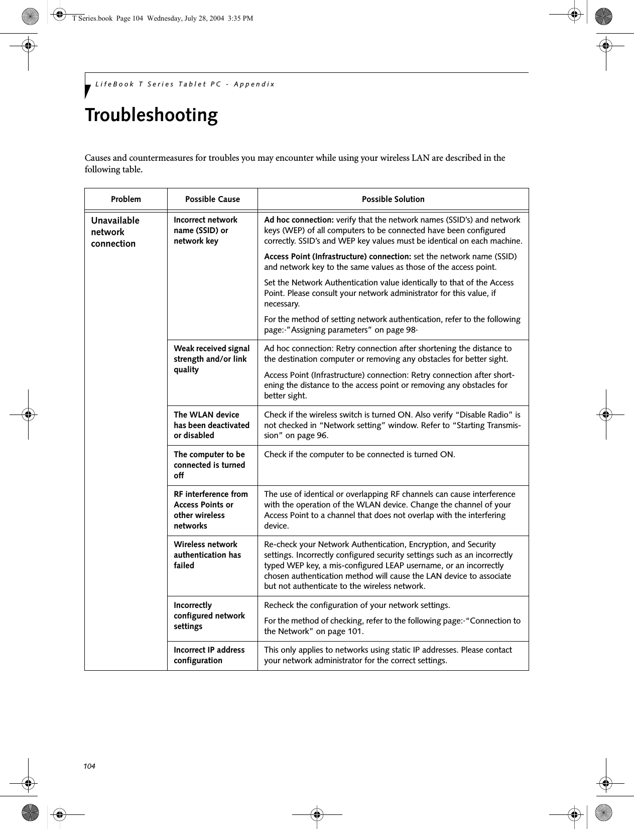
![96LifeBook T Series Tablet PC - AppendixDEACTIVATING THE WLAN DEVICEDeactivation of the WLAN device may be desired in certain circumstances (to extend battery life) or where certain environments require it (e.g., hospitals, clinics, airplanes, etc.). Fujitsu mobile computers employ two methods with which to deactivate the WLAN device, 1) the Wireless On/Off Switch and 2) in Windows using the Intel PROSet, Atheros Client Utility, or Broadcom Wireless Utility software.Deactivation using the Wireless On/Off SwitchThe WLAN device can be deactivated quickly and effi-ciently by toggling the Wireless On/Off Switch to the Off position. (Figure 5-3)The Wireless On/Off switch has no effect on non-Wire-less LAN models.Figure 5-3. Wireless LAN On/Off Switch LocationDeactivation using the Intel PROSet SoftwareThe WLAN device can also be deactivated in Windows using the Intel PROSet Software. The procedure to accomplish this:1. Click [Start]-> [Control Panel].2. If the Control Panel is in Category view, switch to Classic view by clicking "Switch to Classic View" which can be found in the left frame of the Control Panel window. 3. Click on the Intel PROSet for Wireless icon which will execute the Intel PROSet application.4. Select the General tab if it is not already selected.5. Check the Off radio button next to "Switch radio:" then click the [OK] button. Deactivation using Atheros Client Utility software1. Click [Start] -> [Program Files] -> [Atheros] -> Atheros Client Utility.2. Choose Action and click Disable Radio.Deactivation using Broadcom Wireless Utility1. Click [Start] --> [Control Panel] --> [Broadcom Wireless Utility]. The Broadcom Wireless Configu-ration Utility window will be displayed.2. Click the Wireless Networks tab.Click the [Enable Radio] box to clear it, then click the [OK] button. Wireless communications on/off switching will be deactivated and the transmission of radio waves from the wireless LAN will be stoppedACTIVATING THE WLAN DEVICEActivation of the WLAN device can be accomplished using the same methods as the deactivation process■Using the Wireless On/Off Switch■In Windows using the Intel PROSet, Atheros, or Broadcom software.Wireless LANOn/Off SwitchTBD - NEW GRAPHICT Series.book Page 96 Wednesday, July 28, 2004 3:35 PM](https://usermanual.wiki/Fujitsu-Client-Computing/WB0010.Manual-Part-3/User-Guide-463207-Page-22.png)
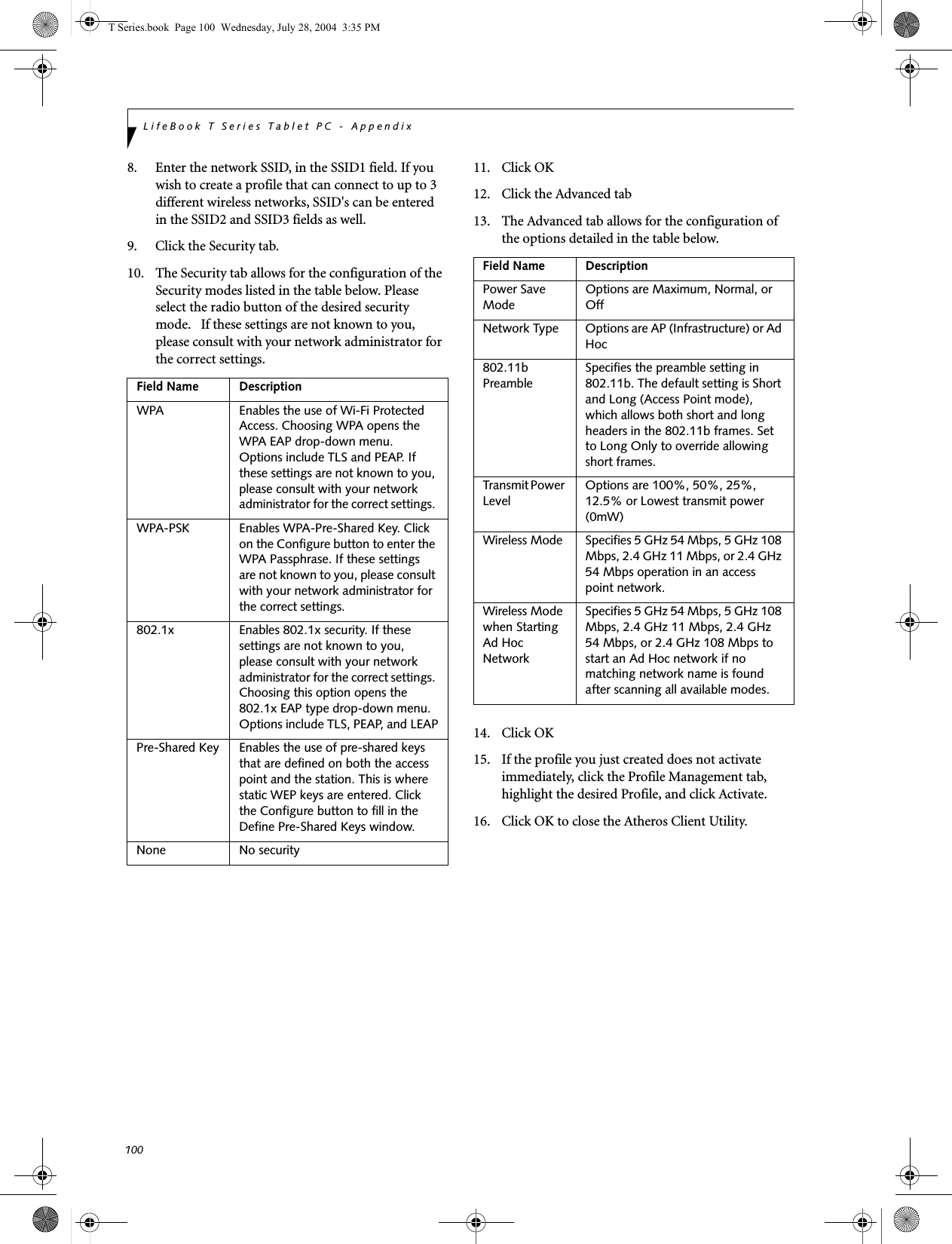
![97WIreless LAN User’s Guide Configuration of the WLAN DeviceThe WLAN Device can be configured to establish wire-less network connectivity using one of the following tools:■Windows XP Wireless Zero Configuration (WZC) - The WZC allows for multiple profile setup and sup-port for most industry standard security solutions. This configuration should be used for the Broadcom WLAN device.■Intel PROSet Software - The Intel PROSet Software allows for multiple profile setup and supports auto-matic profile switching. Support for most industry standard security solutions as well as Cisco Compati-ble Extensions (CCX) is contained in this software.■Atheros Client Utility - The Atheros Client Utility soft-ware allows for multiple profile setups and supports automatic profile switching. Support for most indus-try standard security solutions, as well as Cisco Com-patible Extensions (CCX), is contained in this software.FLOW OF OPERATIONS1. Activate the WLAN Device (See Activating the WLAN Device on page 96 for more information).2. Configure the Wireless Network parameters (See Configure Wireless Network Parameters on page 98 for more information).■Enter the network name (SSID)■Choose the appropriate WLAN architecture (Ad Hoc or Infrastructure)■Choose Authentication method: Open, Shared, WPA, or WPA-PSK■If using static WEP keys, enter static WEP key and choose key index. 3. Configure network settings (See Configure Net-work Parameters on page 98 for more information)■TCP/IP settings■Workgroup or Domain settings.CONFIGURATION USING WIRELESS ZERO CONFIGURATION TOOLThis section explains the procedure to properly configure the WLAN device using the WZC. Pre-defined parameters will be required for this procedure. Please consult with your network administrator for these parameters:Network Name - Also known as the SSIDNetwork Key (WEP) - Required if using static WEP keys. Authentication Type - Open, Shared, WPA, or WPA-PSKProcedure1. Activate the WLAN device using the Wireless On/Off Switch, the Intel PROSet software, or the Atheros Client Utility.2. Click the [Start] button first and then [Control Panel].3. If the Control Panel is in Category view, switch to Classic view by clicking "Switch to Classic View" which can be found in the left frame of the Control Panel window. 4. Double-click the Network Connections icon. A list of previously configured networks will be dis-played. 5. Right-click [Wireless Network Connection] in the list, and then click [Properties] in the menu dis-played.6. Click the [Wireless Networks] tab.7. Click [Refresh], then choose the correct SSID from the [Available Networks] window. Click [Config-ure] and proceed to step 8. Please note that only wireless networks that broadcast their SSID will be displayed. If the SSID of the wireless network is not visible, you must manually add it. This can be accomplished by clicking [Add]8. From within the Association tab configure the appropriate WLAN parameters. Please have ready the following parameters:■Network name (SSID) - ASCII string of up to 33 characters used by the WLAN to logically separate wireless networks. ■Authentication Type - Options include Open, Shared, WPA, or WPA-PSK■Network Key - If Authentication Type is Open or Shared, choices are None or WEP. If Authentica-tion Type is WPA or WPA-PSK, choices are WEP or TKIP.Ad Hoc Networks: All computers in an Ad Hoc network must be assigned with the same SSID and T Series.book Page 97 Wednesday, July 28, 2004 3:35 PM](https://usermanual.wiki/Fujitsu-Client-Computing/WB0010.Manual-Part-3/User-Guide-463207-Page-23.png)
![98LifeBook T Series Tablet PC - Appendixthe checkbox for the field [This is a computer to computer (ad hoc) network, wireless access points are not used.] must be checked.Access Point (Infrastructure) Networks: The SSID must be identical to the SSID of the access point(s) and the checkbox for the following field must be unchecked [This is a computer to computer (ad hoc) network wireless access points are not used.] Refer to the access point manual, or contact your network administrator9. Configure Wireless Network Key parameters (Net-work Authentication and Encryption).a. Choose the Network Authentication method appropriate for your wireless LAN. Options include Open, Shared, WPA, and WPA-PSK.Ad Hoc Networks: Network Authentication settings must be identical for all computers in the Ad Hoc network. Access Point (Infrastructure Networks): Network Authentication setting must be config-ured to match the setting of the Access Point(s). Please contact your network administrator for this information.b. Choose the Encryption method appropriate for your wireless LAN. Options for Open or Shared Authentication are None or WEP. Options for WPA or WPA-PSK are WEP or TKIP.c. If using static WEP keys, clear the check mark from the [The key is provided for me automati-cally] check box. If using an authentication method that uses dynamic WEP (e.g., WPA, WPA-PSK, 802.1x/EAP), the check box should remain checked. Please contact your network administrator for the correct settings.d. Static WEP keys (if applicable) are entered in the [Network Key] box. Configuration of the [Network Key] is not required if the [The key is provided for me automatically] check box is checked.■Static WEP keys entered in ASCII code format will be either five characters (40-bit) or thirteen characters (104-bit) in length. Valid characters are 0 - 9, A - Z.■Static WEP keys entered in hexadecimal code format will be either ten characters (40-bit) or twenty-six characters (104-bit) in length. Valid characters are 0 - 9, A - F.Ad Hoc Networks: Assign the same net-work key to all the personal computers to be connected.Access Point (Infrastructure) Networks: Assign the identical network key that is programmed into the access point. Please contact your network administrator for this information.e. If using static WEP keys, confirm the Network key by re-entering the same data in the [Confirm network key:] field.f. The Key index used must be identical to the transmit key used in the Access Point or other wireless device. This is only applicable when static WEP keys are used. Please contact your network administrator for this information.10. Access Point (Infrastructure) Networks Only: If the wireless network you are establishing connec-tivity to implements an access control security mechanism, configuration of 802.1x parameters may be necessary. Please contact your network administrator for these settings. Configuration of these parameters is not applicable to home users. 11. Click [OK] to close the [Wireless Network] window which will cause the WLAN device to re-establish wireless network connectivity using the recently configured parameters.CONFIGURATION USING INTEL PROSET SOFTWAREThis section explains the procedure to properly configure the WLAN device using the Intel PROSet Soft-ware. Pre-defined parameters will be required for this procedure. Please consult with your network adminis-trator for these parameters:Network Name - Also known as the SSIDNetwork Key (WEP) - Required if using static WEP keys. Authentication Type - Open, Shared, WPA, or WPA-PSKProcedure1. Activate the WLAN device using either the Wireless On/Off Switch or the Intel PROSet software.2. Click the [Start] button first and then [Control Panel].3. If the Control Panel is in Category view, switch to Classic view by clicking "Switch to Classic View" which can be found in the left frame of the Control Panel window. 4. Double-click the icon [Intel PROSet] to execute the Intel PROSet Software.5. From the General page, click the Networks tab. T Series.book Page 98 Wednesday, July 28, 2004 3:35 PM](https://usermanual.wiki/Fujitsu-Client-Computing/WB0010.Manual-Part-3/User-Guide-463207-Page-24.png)
![99WIreless LAN User’s Guide 6. Click the [Add] button. The General Settings dialog displays. 7. From the General page, click the Networks tab. 8. Click the [Add] button. The General Settings dialog displays. 9. Enter a profile name in the Profile Name field. 10. Enter the network SSID, in the Network Name (SSID) field. 11. Click Infrastructure or Ad Hoc for the operating mode. 12. The Mandatory AP option is only used if Infra-structure mode is selected. Use this option to con-nect to a specific access point. Click the Mandatory AP button, enter the MAC address for the access point. Click OK to save the setting and return to the General Settings page. 13. If you are using Cisco CCX, click the Enable Cisco Client eXtentions option to enable Cisco CKIP data encryption on the Security Settings page. If you have checked the Cisco's "Mixed-Cell" box in the Advanced Setting, this option must also be checked. 14. Click Next.15. Click the Security tab16. Select Open, Shared, WPA, or WPA-PSK in the Network Authentication options. 17. Select either None, WEP, CKIP (if Enable Cisco Cli-ent eXtentions is enabled on the General Settings page), or TKIP for the data encryption. 18. If WEP is selected, select either 64 or 128-bit for the Encryption Level. 19. Select the key index 1, 2, 3 or 4. 20. Enter the WEP key if required. If your network does not employ a 802.1x/EAP security mechanism, please skip to step 24.21. Click the 802.1x Enabled checkbox to enable the 802.1x security option. Please contact your network administrator if configuration of this setting is required.22. Select the appropriate 802.1x/EAP Type. Please contact your network administrator if configura-tion of this setting is required.23. After selecting your authentication type, click the Configure button to open the Settings dialog. Enter the user name and password of the user you have created on the authentication server. The user name and password do not have to be the same as name and password of your current Windows user login. The "Server Identity" can be use the default setting. The "Client Certificate" should be the one obtained from your RADIUS server or other certifi-cation server. 24. Click Close to save the settings. 25. From the General settings page, click the new pro-file name shown in the Profile List. Use the up and down arrows to position the priority of the new profile in the priority list. 26. Click the Advanced button to set the network con-nection preferences. 27. Click the Connect button to connect to the net-work. 28. Click OK to close the Intel(R) PROSet for Wireless utilityCONFIGURATION USING ATHEROS CLIENT UTILITY SOFTWAREThis section explains the procedure to properly configure the WLAN device using the Atheros Client Utility. Pre-defined parameters will be required for this procedure. Please consult with your network adminis-trator for these parameters:Network Name - Also known as the SSIDNetwork Key (WEP) - Required if using static WEP keys. Authentication Type - Open, Shared, WPA, or WPA-PSKProcedure1. Activate the WLAN device using either the Wireless On/Off Switch or the Atheros Client Utility2. Click the [Start] button first and then [Control Panel].3. If the Control Panel is in Category view, switch to Classic view by clicking "Switch to Classic View" which can be found in the left frame of the Control Panel window. 4. Double-click the icon [Atheros Client Utility] to execute the Atheros Client Utility.5. From the Current Status page, click the Profile Management tab. 6. If this is your first time using this utility, highlight the profile [Default] and Click the [Modify] button, otherwise Click the [New] button. The General Set-tings dialog displays. 7. From the General page, enter a profile name in the Profile Name field. T Series.book Page 99 Wednesday, July 28, 2004 3:35 PM](https://usermanual.wiki/Fujitsu-Client-Computing/WB0010.Manual-Part-3/User-Guide-463207-Page-25.png)
![101WIreless LAN User’s Guide CONNECTION TO THE NETWORKThis section explains connection to the network.If there is an administrator of the network, contact the network administrator for data settings.Setting the networkPerform the “Setting TCP/IP” and “Confirming the computer and work group names” operations required for network connection.Setting TCP/IP1. Click the [Start] button first and then [Control Panel].2. If the Control Panel is in Category view, switch to Classic view by clicking “Switch to Classic View” under Control Panel the left frame. (If you are already in Classic view, “Switch to Category View” will be displayed.) 3. Double-click [Network Connections]. A list of cur-rently installed networks will be displayed.4. Right-click [Wireless Network Connection] in the list, and then click [Properties] in the menu dis-played. The [Wireless Network Connection Proper-ties] window will be displayed.5. Click the [General] tab if it is not already selected.6. Click [Internet Protocol (TCP/IP] and then click [Properties]. The [Internet Protocol (TCP/IP) Properties] window will be displayed.7. Set the IP address as follows:■For ad hoc connection: Select [Use the following IP address:] and then enter data for [IP address] and [Subnet mask]. See page 107 for IP address setting.■For access point (infrastructure) connection: If your network uses DHCP, select [Obtain an IP address automatically] and [Obtain DNS server address automatically]. If your network uses static IP addresses, consult with your network adminis-trator for the correct IP address settings.8. Click the [OK] button. Processing will return to the [Wireless Network Connection Properties] window.9. Click the [OK] button.10. Close the [Network Connection] window. Following this operation, confirm the names of the computer and the workgroup as follows.Confirming the computer and work group names1. Click the [Start] button, then [Control Panel].2. If the Control Panel is in Category view, switch to Classic view by clicking “Switch to Classic View” under Control Panel the left frame. (If you are already in Classic view, “Switch to Category View” will be displayed.) 3. Double-click the [System] icon. The [System Prop-erties] window will be displayed.4. Click the [Computer Name] tab.5. Confirm the settings of [Full computer name:] and [Workgroup:].a. The setting of [Full computer name:] denotes the name for identifying the computer. Any name can be assigned for each personal computer. Enter the desired name in less than 15 ASCII character code format. Identifiability can be enhanced by entering the model number, the user name, and other factors.b. [Workgroup name] is the group name of the network. Enter the desired name in less than 15 ASCII character code format.For ad hoc connection: Assign the same network name to all personal computers existing on the network.For access point (infrastructure) connection: Assign the name of the work group to be accessed.6. Click the [OK] button. If a message is displayed that requests you to restart the personal computer, click [Yes] to restart the computer.Setting the sharing functionSet the sharing function to make file and/or printer sharing with other network-connected personal computers valid.This operation is not required unless the sharing func-tion is to be used.To change the setting of the IP address, you need to be logged in from Windows as an administrator.To modify the computer name and/or the work group name, you need to be logged in from Windows as an administrator.To change the name, click [Change] and then proceed in accordance with the instruction messages displayed on the screen.T Series.book Page 101 Wednesday, July 28, 2004 3:35 PM](https://usermanual.wiki/Fujitsu-Client-Computing/WB0010.Manual-Part-3/User-Guide-463207-Page-27.png)
![102LifeBook T Series Tablet PC - AppendixThe folder and printer for which the sharing function has been set will be usable from any personal computer present on the network.Setting the Microsoft network-sharing service1. Click the [Start] button first and then [Control Panel]. 2. If the Control Panel is in Category view, switch to Classic view by clicking “Switch to Classic View” under Control Panel the left frame. (If you are already in Classic view, “Switch to Category View” will be displayed.) 3. Double-click [Network Connections]. A list of cur-rently installed networks will be displayed.4. Right-click [Wireless Network Connection] in the list, and then click [Properties] in the menu dis-played. The [Wireless Network Connection Proper-ties] window will be displayed.5. If [File and Printer Sharing for Microsoft Net-works] is displayed, proceed to step 6. If [File and Printer Sharing for Microsoft Networks] is not dis-played, skip to step 7.6. Make sure that the [File and Printer Sharing for Microsoft Networks] check box is checked, and then click the [OK] button. Skip to “Setting file-sharing function”.7. Click [Install]. The [Select Network Component Type] window will be displayed.8. Click [Service], then click the [Add] button. The [Select Network Service] window will be displayed.9. Click [File and Printer Sharing for Microsoft Net-works] and then click the [OK] button. Processing will return to the [Wireless Network Connection Properties] window, and [File and Printer Sharing for Microsoft Networks] will be added to the list.10. Click the [Close] button.Setting the file-sharing functionThe procedure for setting the file-sharing function follows, with the “work” folder in drive C: as an example.1. Click the [Start] button first and then [My Com-puter]. 2. Double-click [Local disk (C:)].3. Right-click the “work” folder (or whichever folder you want to share), and then click [Sharing and Security...] in the menu displayed. The [Folder Name Properties] window will be displayed.4. Click [Sharing] if it isn’t already selected.5. Click the link stating “If you understand the secu-rity risks, but want to share files without running the wizard, click here”.6. Click “Just enable file sharing” and click [OK].7. Check the [Share this folder on the network] check box.8. Click the [OK] button. The folder will be set as a sharable folder, and the display of the icon for the “work.” folder will change.Setting the printer-sharing function1. Click the [Start] button first and then [Printers and FAX]. A list of connected printers will be displayed.2. Right-click the printer for which the sharing func-tion is to be set, and then click [Sharing] in the menu displayed. The property window correspond-ing to the selected printer will be displayed.To share a file and/or the connected printer, you need to be logged in as an administrator. Setting the file-sharing function for the file which has been used to execute Network Setup Wizard is suggested on the screen. For the wireless LAN, however, since security is guaranteed by entry of the network name (SSID) and the network key, the steps to be taken to set the file-sharing function easily without using Network Setup Wizard are given below.To specify the corresponding folder as a read-only folder, select the [Read only] checkbox under the General tab.Setting the printer-sharing function when Network Setup Wizard has been executed is suggested on the screen. For the wireless LAN, however, since security is guaranteed by entry of the network name (SSID) and the network key, the steps to be taken to set the printer-sharing function without using Network Setup Wizard are laid down below.T Series.book Page 102 Wednesday, July 28, 2004 3:35 PM](https://usermanual.wiki/Fujitsu-Client-Computing/WB0010.Manual-Part-3/User-Guide-463207-Page-28.png)
![103WIreless LAN User’s Guide 3. Click the [Sharing] tab.4. Click [Share this printer].5. Enter the sharing printer name in [Share name].6. Click the [OK] button. Confirming connectionAfter you have finished the network setup operations, access the folder whose sharing has been set for other personal computers. Also, confirm the status of the radio waves in case of trouble such as a network connection failure.Connecting your personal computer to another personal computer1. Click [Start] first and then [My Computer]. The [My Computer] window will be displayed in the left frame.2. Click [My Network Places] in the “Other Places” list. The window [My Network Places] will be dis-played.3. Click [View workgroup computers] under Network Tasks in the left frame.4. Double-click the personal computer to which your personal computer is to be connected. The folder that was specified in “Setting the file-sharing func-tion” on page 102 will be displayed.5. Double-click the folder to be accessed.In the case of access point (infrastructure) connection, enter the necessary data for the access point before confirming connection. Refer to the manual of the access point for the access point setup procedure.T Series.book Page 103 Wednesday, July 28, 2004 3:35 PM](https://usermanual.wiki/Fujitsu-Client-Computing/WB0010.Manual-Part-3/User-Guide-463207-Page-29.png)
![107WIreless LAN User’s Guide IP address informationIf IP address is unknown, set IP address as follows:If you have an access point (DHCP server) on the network, set the IP address as follows:[Obtain an IP address automatically]If the IP address is already assigned to the computer in the network, ask the network administrator to check the IP address to be set for the computer.If no access point is found in the network:An IP address is expressed with four values in the range between 1 and 255.Set the each computer as follows: The value in paren-theses is a subnet mask.<Example>Computer A: 192.168.100.2 (255.255.255.0)Computer B: 192.168.100.3 (255.255.255.0)Computer C: 192.168.100.4 (255.255.255.0)::Computer X: 192.168.100.254 (255.255.255.0)IP addressing is much more complicated than can be briefly explained in this document. You are advised to consult with your network administrator for additional information.A DHCP server is a server that automatically assigns IP addresses to computers or other devices in the network. There is no DHCP server for the AdHoc network.T Series.book Page 107 Wednesday, July 28, 2004 3:35 PM](https://usermanual.wiki/Fujitsu-Client-Computing/WB0010.Manual-Part-3/User-Guide-463207-Page-33.png)
![109W Ire less L A N User’s G uid e Using the Bluetooth DeviceThe integrated Bluetooth module is an optional device available for Fujitsu mobile computers. W HAT IS BLUETO O TH?Bluetooth technology is designed as a short-range wire-less link between mobile devices, such as laptop computers, phones, printers, and cameras. Bluetooth technology is used to create Personal Area Networks (PANs) between devices in short-range of each other. W HERE TO FIND INFO RM ATIO NABO UT BLUETO O THThe Bluetooth module contains a robust H elp user’s guide to assist you in learning about operation of the Bluetooth device.To access the Help file, click [Start] -> All Programs, and click on Toshiba. Select Bluetooth, then select User’s Guide.For additional information about Bluetooth Technology, visit the Bluetooth Web site at: www.bluetooth.com.FCC Radiation Exposure StatementThis equipment complies with FCC radiation exposure limits set forth for an uncontrolled environment. T he The transmitters in this device must not be co-located or operated in conjunction with any other antenna or transmitter.Canadian NoticeTo prevent radio interference to the licensed service, this device is intended to be operated indoors and away from windows to provide maximum shielding. Equipment (or its transmit antenna) that is installed outdoors is subject to licensing.WarrantyUsers are not authorized to modify this product. Any modifications invalidate the warranty.This equipment may not be modified, altered, or changed in any way without signed written permission from Fujitsu. Unauthorized modification will void the equipment authorization from the FCC and Industry Canada and the warranty.T Series.book Page 109 Wednesday, July 28, 2004 3:35 PMmaximum power output is less than 20mW and meets the exemption criteria for radiation exposure limits.](https://usermanual.wiki/Fujitsu-Client-Computing/WB0010.Manual-Part-3/User-Guide-463207-Page-35.png)