Fujitsu Client Computing WB0014 LIFEBOOK E SERIES WITH CAL2 11ABG WLAN & BT User Manual Appendix H Pt2
Fujitsu Limited LIFEBOOK E SERIES WITH CAL2 11ABG WLAN & BT Appendix H Pt2
UserManual.wiki
>
Fujitsu Client Computing
>
WB0014 User Manual
>
USERS MANUAL 2
Contents
1.
USERS MANUAL 1
2.
USERS MANUAL 2
USERS MANUAL 2
Navigation menu
Upload a User Manual
Namespaces
Wiki Guide
HTML
PDF
Info
Views
User Manual
Discussion / Help
Navigation


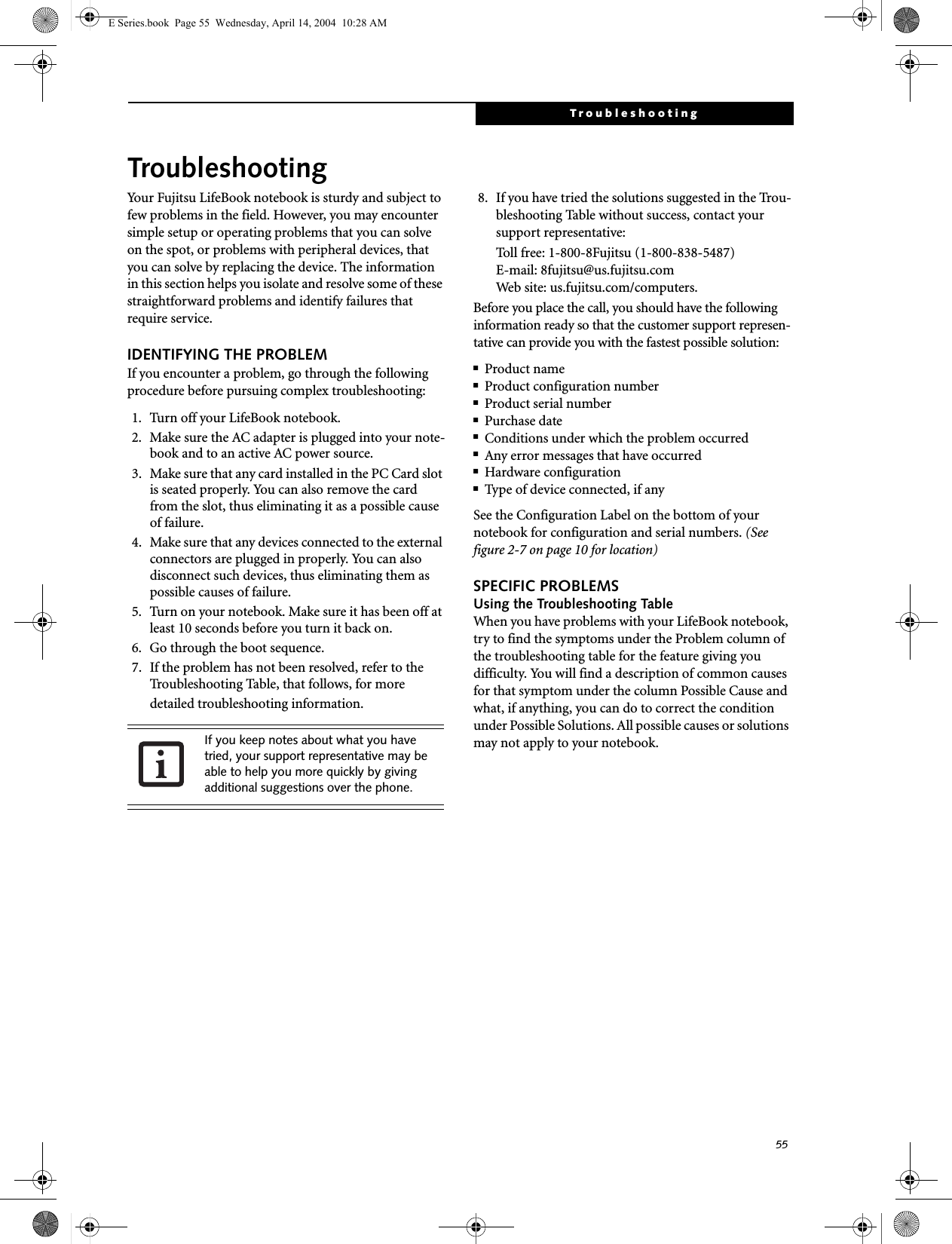
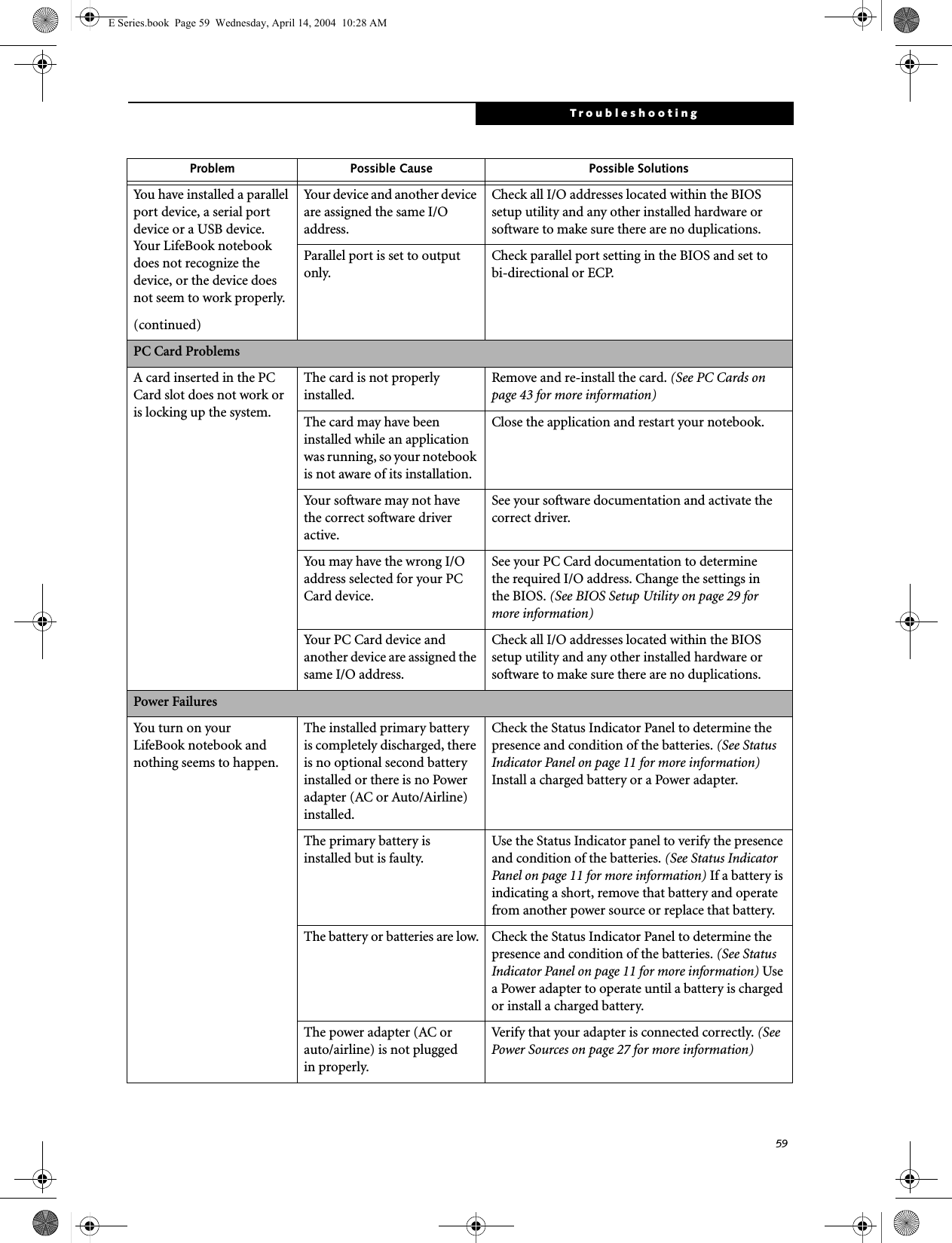
![61TroubleshootingThe batteries seem to discharge too quickly.(continuedThe batteries have been exposed to high temperatures.Replace the batteries.The batteries are too hot or too cold. Restore the notebook to normal operating tempera-ture. The Charging icon on the Status Indicator panel will flash when the battery is outside itsoperating range.Shutdown and Startup ProblemsThe Suspend/Resume button does not work.The Suspend/Resume button is disabled from the Advanced submenu of the Power menu of the setup utility. Enable the button from the setup utility.You did not hold the button in long enough.Hold the button longer. This may need to be a few seconds if your application is preventing the CPU from checking for button pushes.There may be a conflict with the application software.Close all applications and try the button again.The system powers up, and displays power on informa-tion, but fails to load the operating system.The boot sequence settings of the setup utility are not compatible with your configuration.Set the operating source by pressing the [ESC] key while the Fujitsu logo is on screen or use the [F2] key and enter the setup utility and adjust the source settings from the Boot menu. (See BIOS Setup Utility on page 29 for more information)You have a secured system requiring a password to load your operating system.Make sure you have the right password. Enter the setup utility and verify the Security settings and modify them as accordingly. (See BIOS Setup Utility on page 29 for more information)Internal hard drive was not detected.Use the BIOS setup utility or Primary Master submenu, located within the Main menu, to try to auto detect the internal hard drive.An error message is displayed on the screen during the notebook (boot) sequence.Power On Self Test (POST) has detected a problem.See the Power On Self Test (POST) messages to determine the meaning and severity of the problem. Not all messages are errors; some are simply status indicators. (See Power On Self Test Messages on page 64 for more information)Your notebook appears to change setup parameters when you start it.BIOS setup changes were not saved when you made them and exited the BIOS setup utility returning it to previous settings.Make sure you select Save Changes And Exit when exiting the BIOS setup utility.The BIOS CMOS hold-up battery has failed.Contact your support representative for repairs. This is not a user serviceable part but has a normal life of 3 to 5 years.Your system display won’t turn on when the system is turned on or when the system has resumed.The system may be password-protected.Check the status indicator panel to verify that the Security icon is blinking. If it is blinking, enter your password.Problem Possible Cause Possible SolutionsE Series.book Page 61 Wednesday, April 14, 2004 10:28 AM](https://usermanual.wiki/Fujitsu-Client-Computing/WB0014.USERS-MANUAL-2/User-Guide-478054-Page-10.png)
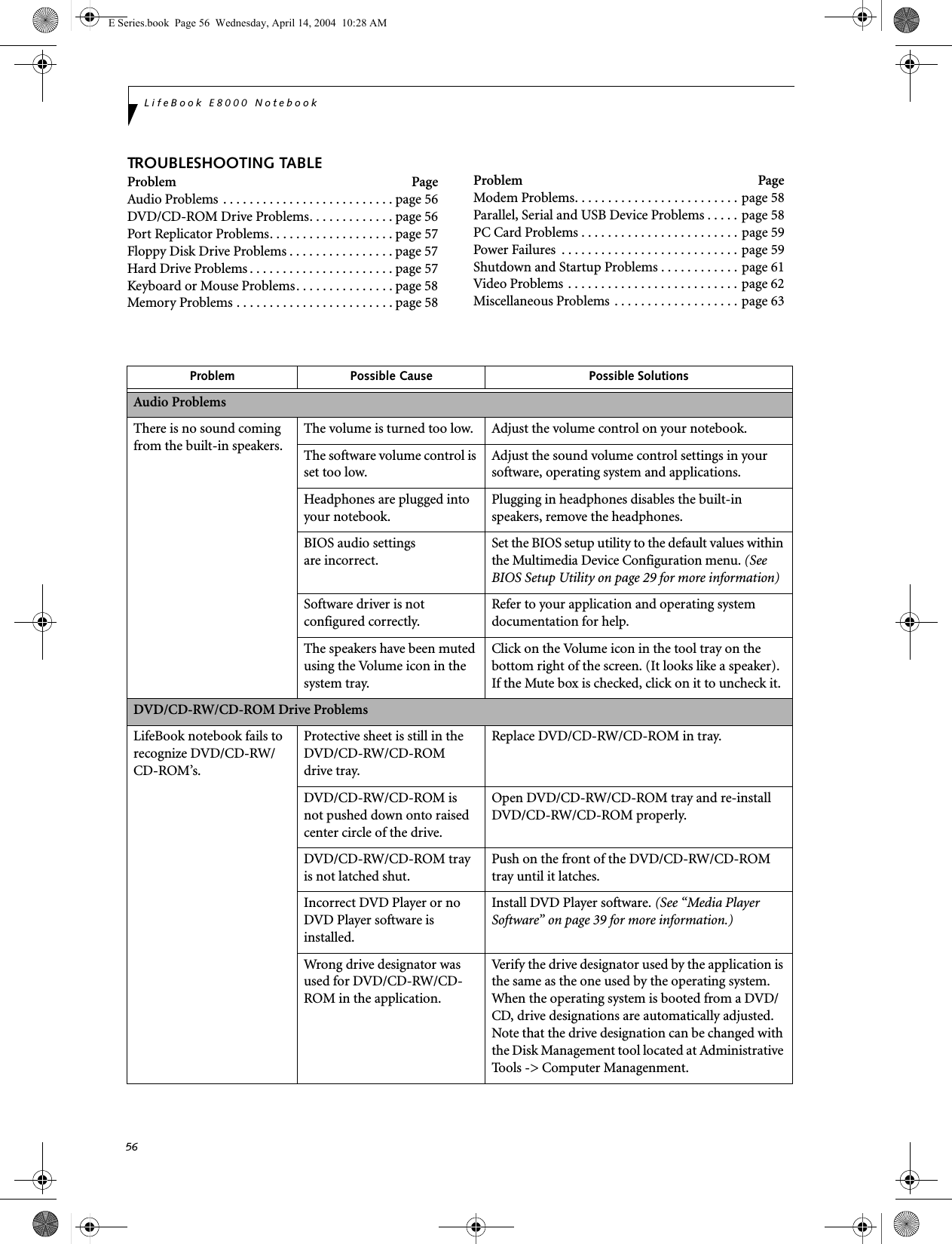
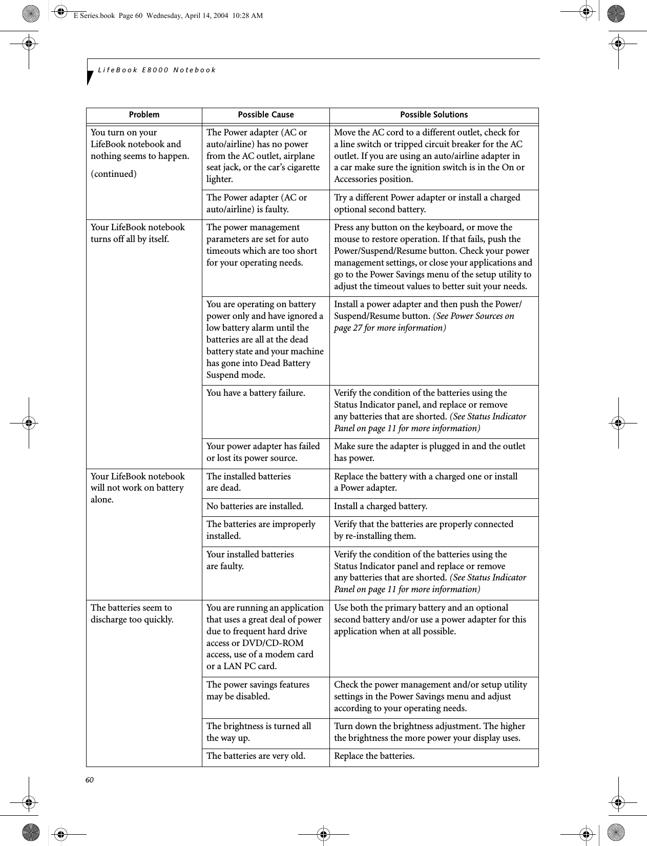
![62LifeBook E8000 NotebookVideo ProblemsThe built-in display is blank when you turn on your LifeBook notebook.Something is pushing on the Closed Cover switch. Clear the Closed Cover switch. (See figure 2-3 on page 6 for location)The notebook is set for an external monitor only.Pressing [F10] while holding down the [Fn] key allows you to change your selection of where tosend your display video. Each time you press the combination of keys you will step to the nextchoice. The choices, in order are: built-in display only, external monitor only, both built-in display and external monitor.The angle of the display and the brightness settings are not adequate for your lighting conditions.Move the display and the brightness control until you have adequate visibility.The power management time-outs may be set for very short intervals and you failed to notice the display come onand go off again.Press any button the keyboard, or move the mouse to restore operation. If that fails, push the Power/Suspend/Resume button. (The display may be shut off by Standy mode, Auto Suspend or Video Timeout)The LifeBook notebook turned on with a series of beeps and your built-in display is blank.Power On Self Test (POST)has detected a failure which does not allow the displayto operate. Contact your support representative.The display goes blank by itself after you have been using it.The notebook has gone into Video timeout, Standby mode, Suspend mode or Save-to-Disk mode because you have not used it for a period of time.Press any button on the keyboard, or move the mouse to restore operation. If that fails, push the Power/Suspend/Resume button. Check your power management settings, or close your applications and go to the Power Savings menu of the setup utility to adjust the timeout values to better suit your operation needs. (See BIOS Setup Utility on page 29 for more information)The power management time-outs may be set for very short intervals and you failed to notice the display come onand go off again.Press any button on the keyboard, or move the mouse to restore operation. If that fails, push the Power/Suspend/Resume button. (The display may be shut off by Standby Mode, Auto Suspend or Video Timeout)Something is pushing on the Closed Cover switch.Check the Closed Cover switch. (See figure 2-3 on page 6 for location)Your system display won’t turn on when the system is turned on or when the system has resumed.The system may be password-protected.Check the status indicator panel to verify that the Security icon is blinking. If it is blinking, enter your password.The Built-in Display does not close.A foreign object, such as a paper clip, is stuck between the display and the keyboard.Remove all foreign objects from the keyboard.Problem Possible Cause Possible SolutionsE Series.book Page 62 Wednesday, April 14, 2004 10:28 AM](https://usermanual.wiki/Fujitsu-Client-Computing/WB0014.USERS-MANUAL-2/User-Guide-478054-Page-11.png)
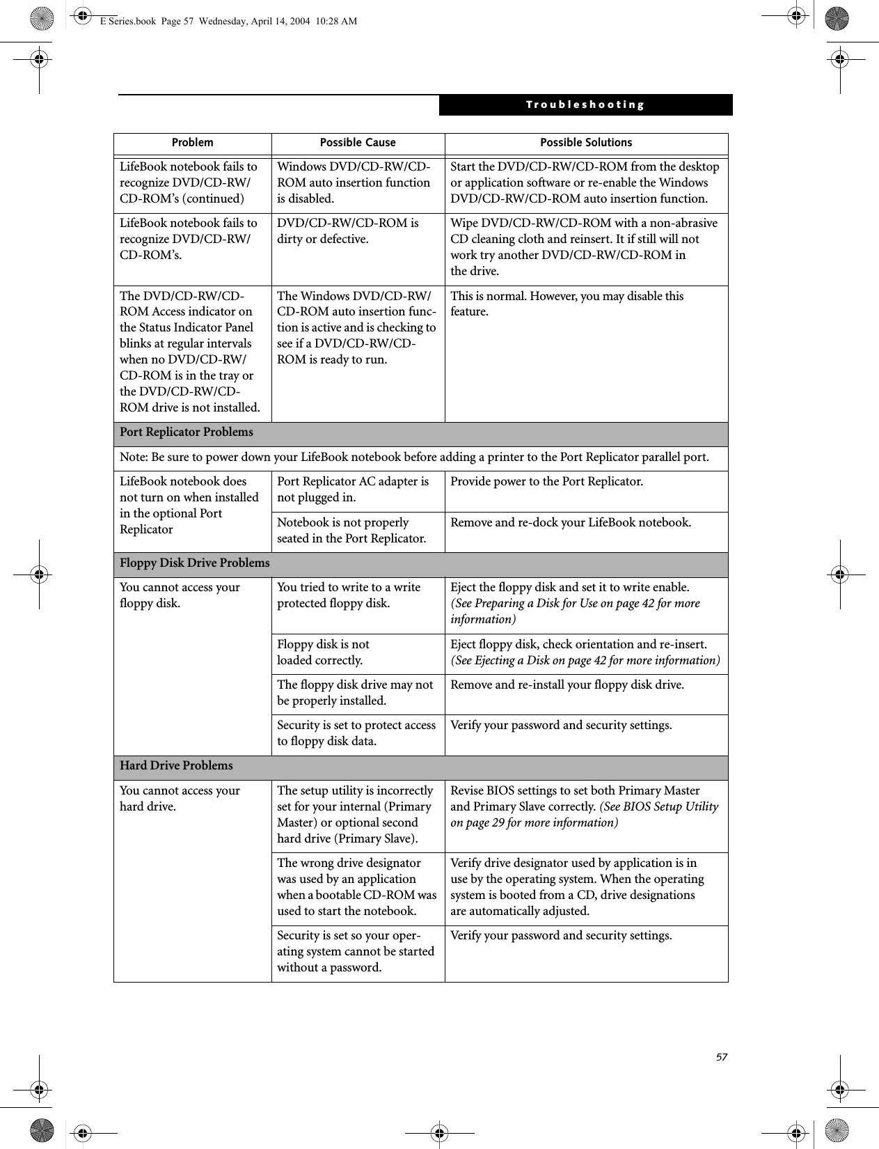
![63TroubleshootingThe Built-in Display has bright or dark spots.If the spots are very tiny and few in number, this is normal for a large LCD display.This is normal; do nothing.If the spots are numerous or large enough to interfere with your operation needs.Display is faulty; contact your support representative.The application display uses only a portion of your screen and is surrounded by a dark frame.You are running an application that does not support 800 x 600/1024 x 768 pixel resolution display and display compres-sion is enabled.Display compression gives a clearer but smaller display for applications that do not support 800 x 600/1024 x 768 pixel resolution. You can fill the screen but have less resolution by changing your display compression setting, (See the Video Features submenu, located within the Advanced menu of the BIOS. (See BIOS Setup Utility on page 29 for more information)The Display is dark when on battery power.The Power Management utility default is set on low brightness to conserve power.Press [Fn] + [F7] to increase brightness or double-click on the battery gauge and adjust Power Control under battery settings.You have connected an external monitor andit does not displayany information.Your BIOS setup is not set to enable your external monitor.Try toggling the video destination by pressing [Fn] and [F10] together, or check your BIOS setup and enable your external monitor. (See the Video Features submenu, located within the Advanced Menu of the BIOS. (See BIOS Setup Utility on page 29 for more information)Your external monitor is not properly installed. Reinstall your device. (See External Monitor Port on page 52 for more information)Your operating system soft-ware is not setup with the correct software driver forthat device. Check your device and operating systemdocumentation and activate the proper driver.You have connected an external monitor and it does not come on.Your external monitor is not compatible with your LifeBook notebook.See your monitor documentation and theExternal Monitor Support portions of theSpecifications section. (See Specifications on page 77 for more information)Miscellaneous ProblemsAn error message is displayed on the screen during the operation ofan application.Application software often has its own set of error message displays. See your application manual and help displays screens for more information. Not all messages are errors some may simply be status.Problem Possible Cause Possible SolutionsE Series.book Page 63 Wednesday, April 14, 2004 10:28 AM](https://usermanual.wiki/Fujitsu-Client-Computing/WB0014.USERS-MANUAL-2/User-Guide-478054-Page-12.png)
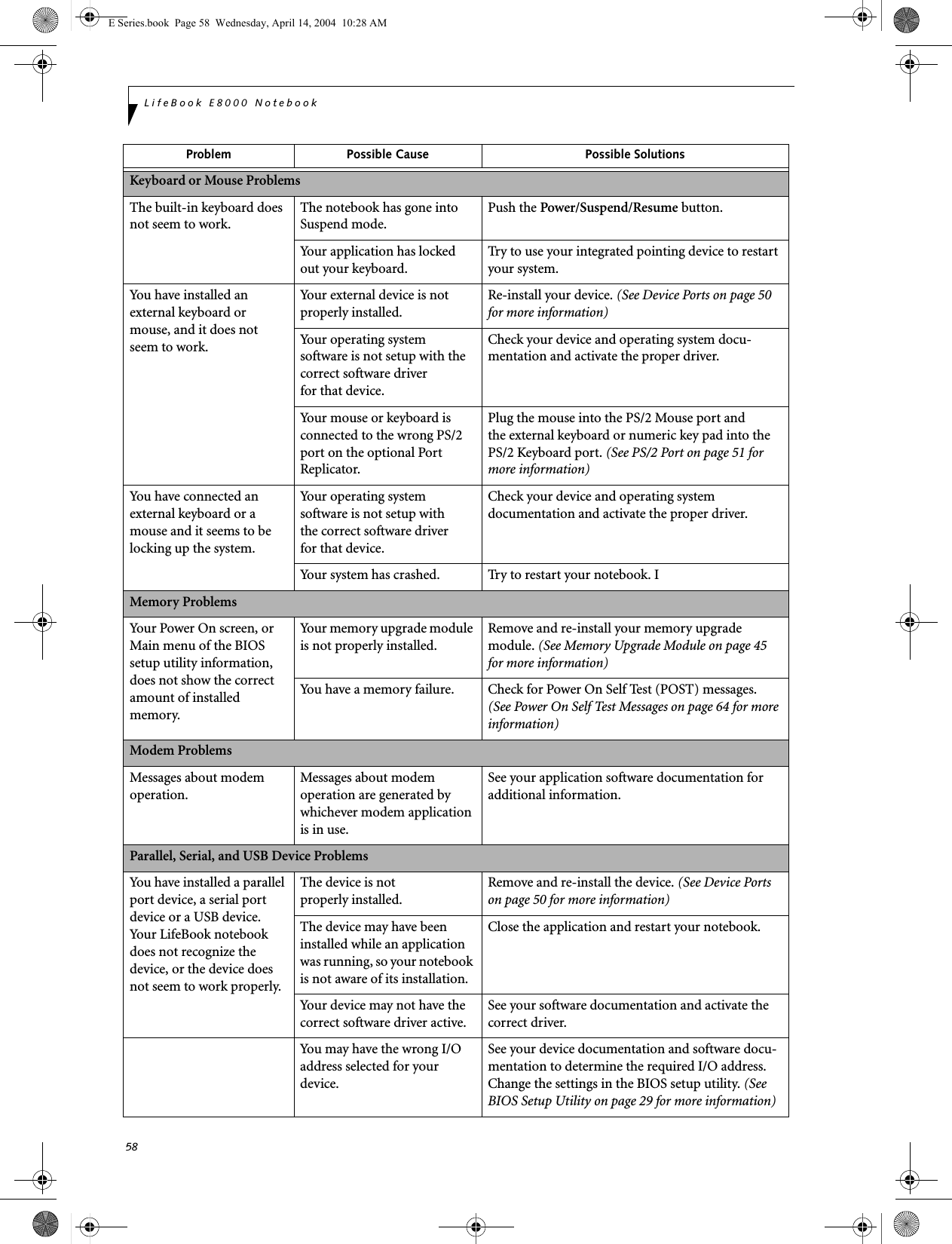
![65Troubleshooting*Parity Check 2 nnnn Parity error found in the I/O bus. BIOS attempts to locate the address and display it on the screen. If it cannot locate the address, it displays ????. This is apotentially data-destroying failure. Contact yoursupport representative.*Press <F1> to resume, <F2> to SETUP Displayed after any recoverable error message. Pressthe [F1] key to continue the boot process or the [F2]key to enter Setup and change any settings.*Previous boot incomplete – Default configuration used Previous Power On Self Test did not complete success-fully. The Power On Self Test will load default values and offer to run Setup. If the previous failure was caused by incorrect values and they are not corrected, the next boot will likely fail also. If using the default settings does not allow you to complete a successful boot sequence, you should turn off the power and contact your support representative.*Real time clock error Real-time clock fails BIOS test. May require board repair. Contact your support representative.*Shadow RAM Failed at offset: nnnn Shadow RAM failed at offset nnnn of the 64k block at which the error was detected. You are risking data corrup-tion if you continue. Contact your support representative.nnnn Shadow RAM Passed Where nnnn is the amount of shadow RAM in kilobytes successfully tested.*System battery is dead – Replace and run SETUP The BIOS CMOS RAM memory hold up battery is dead. This is part of your BIOS and is a board mounted battery which requires a support representative to change. You can continue operating but you will have to use setup utility default values or reconfigure your setup utility every time you turn off your notebook. This battery has an expected life of 2 to 3 years.System BIOS shadowed System BIOS copied to shadow RAM.*System CMOS checksum bad – run SETUP BIOS CMOS RAM has been corrupted or modified incorrectly, perhaps by an application program that changes data stored in BIOS memory. Run Setup and reconfigure the system.*System RAM Failed at offset: nnnn System memory failed at offset nnnn of in the 64k block at which the error was detected. This means that there is a fault in your built-in memory. If you continue to operate, you risk corrupting your data. Contact your support representative for repairs.nnnn System RAM PassedWhere nnnn is the amount of system memory inkilobytes successfully tested.*System timer error The timer test failed. The main clock that operates the computer is faulty. Requires repair of system board. Contact your support representative for repairs.UMB upper limit segment address: nnnn Displays the address of the upper limit of Upper Memory Blocks, indicating released segments of the BIOS memory which may be reclaimed by a virtual memory manager.Video BIOS shadowed Video BIOS successfully copied to shadow RAM.EMERGENCY MEDIA PLAYER DRIVE TRAY RELEASEIf for some reason the eject button fails, you can open the DVD/CD-ROM tray with a paper clip or similar tool inserted into the eject hole in the far right side of the front of the tray. Straighten one side of a paper clipand push it gently into the hole. The tray will pop outa short distance.MODEM RESULT CODESThe operating system and application software that is factory installed detects the modem characteristics and provides the necessary command strings to operate the modem. The internal modem operation is controlled by generic AT commands from the operating system and application software. The standard long form result codes may, in some cases, be displayed on your screen to keep you informed of the actions of your modem. The operating system and application software may suppress display of the result codes. Examples of result codes are:■OK■NO CARRIER■NO DIALTONE■CONNECT 53000 (Connection complete at 53,000 bps.)■ERROR■FAX■RING (This means an incoming call.)■BUSY■NO ANSWERWhen using the internal modem with applicationsthat are not factory installed refer to theapplication documentation.E Series.book Page 65 Wednesday, April 14, 2004 10:28 AM](https://usermanual.wiki/Fujitsu-Client-Computing/WB0014.USERS-MANUAL-2/User-Guide-478054-Page-14.png)
![66LifeBook E8000 NotebookRESTORING YOUR PRE-INSTALLED SOFTWAREThe Drivers and Applications Restore (DAR) CD contains:■Sets of device drivers and Fujitsu utilities (in specific directories) that are unique to your LifeBook note-book configuration for use as documented below.■A link to the Drive Image Special Edition (DISE) utility on your hard disk drive.■Read-me files that provide additional use information for items on this CD-ROM.DRIVE IMAGE SPECIAL EDITION (DISE)PowerQuest Drive Image Special Edition (DISE) provides a way to restore your computer if you experi-ence a hard disk crash or other system failure. Fujitsu has used DISE to create an image of everything installed on the computer at the time you purchased it. The image is saved on a separate partition on the hard disk. You can use DISE to restore the factory image and return your computer to the state in which it was shipped from Fujitsu.Although it is not necessary, you can use DISE to store additional image files that you create. For example, if you install several applications and save data files on your hard disk, you can create a new image file that includes them and then save that image file on the hard disk. Then, in the event of a hard disk failure, you can restore the image that includes the applications and data files you use.Creating a Backup ImageYou can create a backup image of your C:\ drive at any time. The C:\ partition must be a FAT, FAT32, or NTFS partition, and it must be directly before the backup partition on your hard disk.There are two ways to implement the DISE utility: When booting up the system, or from the desktop. Creating a backup image when booting upBefore creating a backup image at boot-up, you must first change the boot-up priority in the BIOS so that the system will go to the CD drive first, rather than trying to boot-up from the hard drive or an external floppy disk drive.To change the boot-up priority:1. Start your system and press the [F2] key when the Fujitsu logo appears. You will enter the BIOS Setup Utility.2. Using the arrow keys, go to the Boot menu.3. Arrow down to the Boot Device Priority submenu and press [Enter].4. Arrow down to the CD-ROM drive in the list, and press the space bar (or the + key) to move the CD-ROM drive to the top of the list. (The system attempts to boot from the devices in the order in which they are listed.)5. Press [F10], then click on [Yes] to exit the BIOS Setup Utility and return to the boot process.After you have changed the boot priority, you can create a backup image when you are booting up:1. Install the DAR CD in the drive prior to booting up. When bootup begins, a message will appear informing you that continuing to boot from the CD will overwrite all information on the hard drive, including saved files, and restore the hard drive to its factory configuration. 2. When you are asked if you want to restore the factory image, click [Y]es.Creating a backup image from the desktopTo create a backup image from the desktop, select Drive Image SE from the Program list. You will initially be prompted to create a backup diskette. It is not necessary to create the backup diskette, since the DAR CD performs the same function.1. At the Drive Image Special Edition main screen, click Options> Create New Backup. DISE displays a warning that it must go to DOS to create the image.3. Click Yes .DISE creates an image file in the backup partition. If you created a backup image previously, the new image overwrites the old one.If the DAR CD is in the drive when you boot up the system, a message will appear informing you that continuing to boot from the CD will overwrite all information on the hard drive, including saved files, and restore the hard drive to its factory configuration. If you wish to install drivers or applications only from the CD, remove the disk from the drive, reboot the system, and insert the CD after Windows has started.If you have access to the internet, visit the Fujitsu Support web site at us.fujitsu.com/computers to check for the most current information, drivers and hints on how to perform recovery and system updates.Using the DISE feature will reduce the amount of usable disk space on your hard disk drive.E Series.book Page 66 Wednesday, April 14, 2004 10:28 AM](https://usermanual.wiki/Fujitsu-Client-Computing/WB0014.USERS-MANUAL-2/User-Guide-478054-Page-15.png)
![67TroubleshootingEnlarging the Backup PartitionIf there is not enough unused space in the backup parti-tion on your hard disk, DISE will resize the partition. DISE will display the minimum, maximum, and recom-mended sizes for the backup partition. You choose the size you want.DISE takes the space from the FAT, FAT32, or NTFS partition that you are backing up. If there is not enough unused space in that partition to take, you will not be able to resize the backup partition and create an image file. You can delete files from the FAT, FAT32, or NTFS partition to create more unused space on the hard disk.Restoring a Backup ImageYou can restore either a factory image or a backup image you created. Be aware that restoring a backup image will replace the contents of the C:\ partition with the image you restore.1. Disable virus protection software. If virus protection software is enabled, DISE will hang.2. From the DISE main window, click Options > Restore Backup to restore an image you created, or click Options > Restore Factory Backup to restore the factory image.DISE shuts down to DOS and restores the image file.Re-Installing Individual Drivers and Applications The Drivers and Application CD can be used to selec-tively re-install drivers and/or applications that may have been un-installed or corrupted. To re-install drivers and/or applications:1. Boot up the system and insert the DAR CD after Windows has started. The LifeBook Easy Installation screen appears. 2. Select the drivers and applications you want to install from the list that is displayed.3. Click [Start]. Follow the prompts that appear to complete installation of the selected drivers and/or applications.AUTOMATICALLY DOWNLOADING DRIVER UPDATESYour system has a convenient tool called the Fujitsu Driver Update (FDU) utility. With FDU, you can choose to automatically or manually go to the Fujitsu site to check for new updates for your system.The FDU icon should appear in the system tray at the bottom right of your screen (roll the cursor over the icons to find the correct one). If the FDU icon does not appear in the system tray, it can be started by going to [Start] -> All Programs, and clicking on Fujitsu Driver Update; this will create the icon automatically.To invoke the FDU menu, you can either right-click on the FDU icon or hold the pen on the icon for a couple of seconds until the menu appears. The menu contains the following items:■Check for updates nowAllows for manual driver update search. The first time it is used, you are prompted to agree to a user agreement. After clicking on the icon, the FDU auto-matically connects with the Fujitsu site to check for updates and downloads them. While downloading, the icon has a red bar through it, indicating that it cannot be used while the download is in process. When the update is complete, a message appears informing you of the fact.■Enable Automatic Update NotificationsAutomatically searches for new updates on a regular basis (approximately every 3 days).■Show update historyBrings up a screen that displays a history of updates that have been made via the FDU.■About Fujitsu Driver UpdateDisplays the FDU version number and copyright information■Fujitsu Driver Update ReadmeDisplays the FDU readme.E Series.book Page 67 Wednesday, April 14, 2004 10:28 AM](https://usermanual.wiki/Fujitsu-Client-Computing/WB0014.USERS-MANUAL-2/User-Guide-478054-Page-16.png)


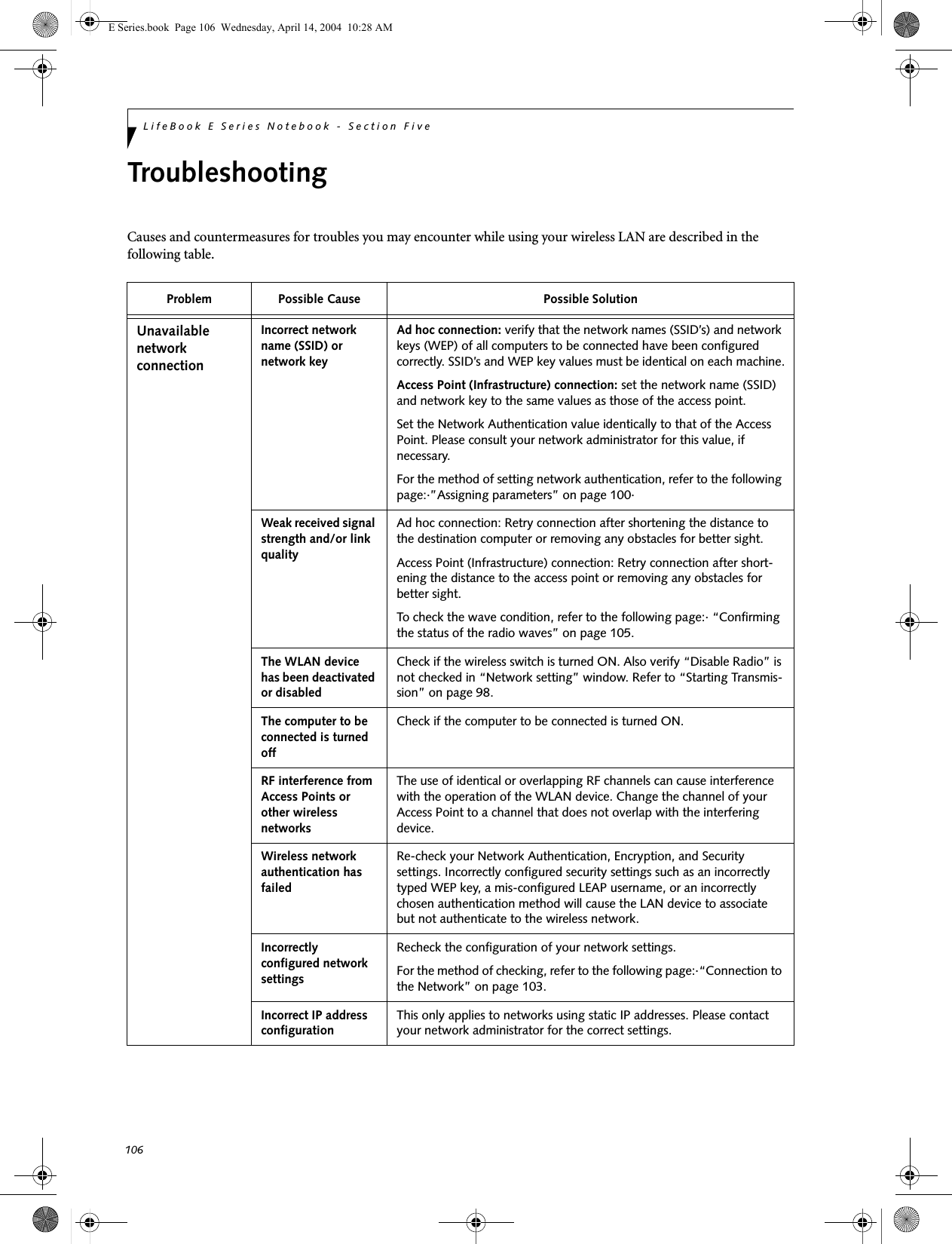
![98LifeBook E Series Notebook - Section FiveThe Wireless On/Off switch has no effect on non-Wire-less LAN models.Figure 5-3. Wireless LAN On/Off Switch LocationDeactivation using the Intel PROSet SoftwareThe WLAN device can also be deactivated in Windows using the Intel PROSet Software. The procedure to accomplish this:1. Click [Start]-> [Control Panel].2. If the Control Panel is in Category view, switch to Classic view by clicking "Switch to Classic View" which can be found in the left frame of the Control Panel window. 3. Double-click on the Intel PROSet for Wireless icon which will execute the Intel PROSet application.4. Select the General tab if it is not already selected.5. Check the Off radio button next to "Switch radio:" then click the [OK] button. Deactivation using Atheros Client Utility software1. Click [Start] -> [Program Files] -> [Atheros] -> Atheros Client Utility.2. Choose Action and click Disable Radio.ACTIVATING THE WLAN DEVICEActivation of the WLAN device can be accomplished using the same methods as the deactivation process■Using the Wireless On/Off Switch■In Windows using the Intel PROSet Software or Atheros SoftwareWireless LANOn/Off SwitchE Series.book Page 98 Wednesday, April 14, 2004 10:28 AM](https://usermanual.wiki/Fujitsu-Client-Computing/WB0014.USERS-MANUAL-2/User-Guide-478054-Page-47.png)
![99WIreless LAN User’s Guide Configuration of the WLAN DeviceThe WLAN Device can be configured to establish wire-less network connectivity using one of the following tools:■Windows XP Wireless Zero Configuration (WZC) - The WZC allows for multiple profile setup and sup-port for most industry standard security solutions. ■Intel PROSet Software - The Intel PROSet Software allows for multiple profile setup and supports auto-matic profile switching. Support for most industry standard security solutions as well as Cisco Compati-ble Extensions (CCX) is contained in this software.■Atheros Client Utility - The Atheros Client Utility soft-ware allows for multiple profile setups and supports automatic profile switching. Support for most indus-try standard security solutions, as well as Cisco Com-patible Extensions (CCX), is contained in this software.FLOW OF OPERATIONS1. Activate the WLAN Device (See Activating the WLAN Device on page 98 for more information).2. Configure the Wireless Network parameters (See Configure Wireless Network Parameters on page 100 for more information).■Enter the network name (SSID)■Choose the appropriate WLAN architecture (Ad Hoc or Infrastructure)■Choose Authentication method: Open, Shared, WPA, or WPA-PSK■If using static WEP keys, enter static WEP key and choose key index. 3. Configure network settings (See Configure Net-work Parameters on page 100 for more informa-tion)■TCP/IP settings■Workgroup or Domain settings.CONFIGURATION USING WIRELESS ZERO CONFIGURATION TOOLThis section explains the procedure to properly configure the WLAN device using the WZC. Pre-defined parameters will be required for this procedure. Please consult with your network administrator for these parameters:Network Name - Also known as the SSIDNetwork Key (WEP) - Required if using static WEP keys. Authentication Type - Open, Shared, WPA, or WPA-PSKProcedure1. Activate the WLAN device using the Wireless On/Off Switch, the Intel PROSet software, or the Atheros Client Utility.2. Click the [Start] button first and then [Control Panel].3. If the Control Panel is in Category view, switch to Classic view by clicking "Switch to Classic View" which can be found in the left frame of the Control Panel window. 4. Double-click the Network Connections icon. A list of previously configured networks will be dis-played. 5. Right-click [Wireless Network Connection] in the list, and then click [Properties] in the menu dis-played.6. Click the [Wireless Networks] tab.7. Click [Refresh], then choose the correct SSID from the [Available Networks] window. Click [Config-ure] and proceed to step 8. Please note that only wireless networks that broadcast their SSID will be displayed. If the SSID of the wireless network is not visible, you must manually add it. This can be accomplished by clicking [Add]8. From within the Association tab configure the appropriate WLAN parameters. Please have ready the following parameters:■Network name (SSID) - ASCII string of up to 33 characters used by the WLAN to logically separate wireless networks. ■Authentication Type - Options include Open, Shared, WPA, or WPA-PSK■Network Key - If Authentication Type is Open or Shared, choices are None or WEP. If Authentica-tion Type is WPA or WPA-PSK, choices are WEP or TKIP.Ad Hoc Networks: All computers in an Ad Hoc network must be assigned with the same SSID and E Series.book Page 99 Wednesday, April 14, 2004 10:28 AM](https://usermanual.wiki/Fujitsu-Client-Computing/WB0014.USERS-MANUAL-2/User-Guide-478054-Page-48.png)
![100LifeBook E Series Notebook - Section Fivethe checkbox for the field [This is a computer to computer (ad hoc) network, wireless access points are not used.] must be checked.Access Point (Infrastructure) Networks: The SSID must be identical to the SSID of the access point(s) and the checkbox for the following field must be unchecked [This is a computer to computer (ad hoc) network wireless access points are not used.] Refer to the access point manual, or contact your network administrator9. Configure Wireless Network Key parameters (Net-work Authentication and Encryption).a. Choose the Network Authentication method appropriate for your wireless LAN. Options include Open, Shared, WPA, and WPA-PSK.Ad Hoc Networks: Network Authentication settings must be identical for all computers in the Ad Hoc network. Access Point (Infrastructure Networks): Network Authentication setting must be config-ured to match the setting of the Access Point(s). Please contact your network administrator for this information.b. Choose the Encryption method appropriate for your wireless LAN. Options for Open or Shared Authentication are None or WEP. Options for WPA or WPA-PSK are WEP or TKIP.c. If using static WEP keys, clear the check mark from the [The key is provided for me automati-cally] check box. If using an authentication method that uses dynamic WEP (e.g., WPA, WPA-PSK, 802.1x/EAP), the check box should remain checked. Please contact your network administrator for the correct settings.d. Static WEP keys (if applicable) are entered in the [Network Key] box. Configuration of the [Network Key] is not required if the [The key is provided for me automatically] check box is checked.■Static WEP keys entered in ASCII code format will be either five characters (40-bit) or thirteen characters (104-bit) in length. Valid characters are 0 - 9, A - Z.■Static WEP keys entered in hexadecimal code format will be either ten characters (40-bit) or twenty-six characters (104-bit) in length. Valid characters are 0 - 9, A - F.Ad Hoc Networks: Assign the same net-work key to all the personal computers to be connected.Access Point (Infrastructure) Networks: Assign the identical network key that is programmed into the access point. Please contact your network administrator for this information.e. If using static WEP keys, confirm the Network key by re-entering the same data in the [Confirm network key:] field.f. The Key index used must be identical to the transmit key used in the Access Point or other wireless device. This is only applicable when static WEP keys are used. Please contact your network administrator for this information.10. Access Point (Infrastructure) Networks Only: If the wireless network you are establishing connec-tivity to implements an access control security mechanism, configuration of 802.1x parameters may be necessary. Please contact your network administrator for these settings. Configuration of these parameters is not applicable to home users. 11. Click [OK] to close the [Wireless Network] window which will cause the WLAN device to re-establish wireless network connectivity using the recently configured parameters.CONFIGURATION USING INTEL PROSET SOFTWAREThis section explains the procedure to properly configure the WLAN device using the Intel PROSet Soft-ware. Pre-defined parameters will be required for this procedure. Please consult with your network adminis-trator for these parameters:Network Name - Also known as the SSIDNetwork Key (WEP) - Required if using static WEP keys. Authentication Type - Open, Shared, WPA, or WPA-PSKProcedure1. Activate the WLAN device using either the Wireless On/Off Switch or the Intel PROSet software.2. Click the [Start] button first and then [Control Panel].3. If the Control Panel is in Category view, switch to Classic view by clicking "Switch to Classic View" which can be found in the left frame of the Control Panel window. 4. Double-click the icon [Intel PROSet] to execute the Intel PROSet Software.5. From the General page, click the Networks tab. E Series.book Page 100 Wednesday, April 14, 2004 10:28 AM](https://usermanual.wiki/Fujitsu-Client-Computing/WB0014.USERS-MANUAL-2/User-Guide-478054-Page-49.png)
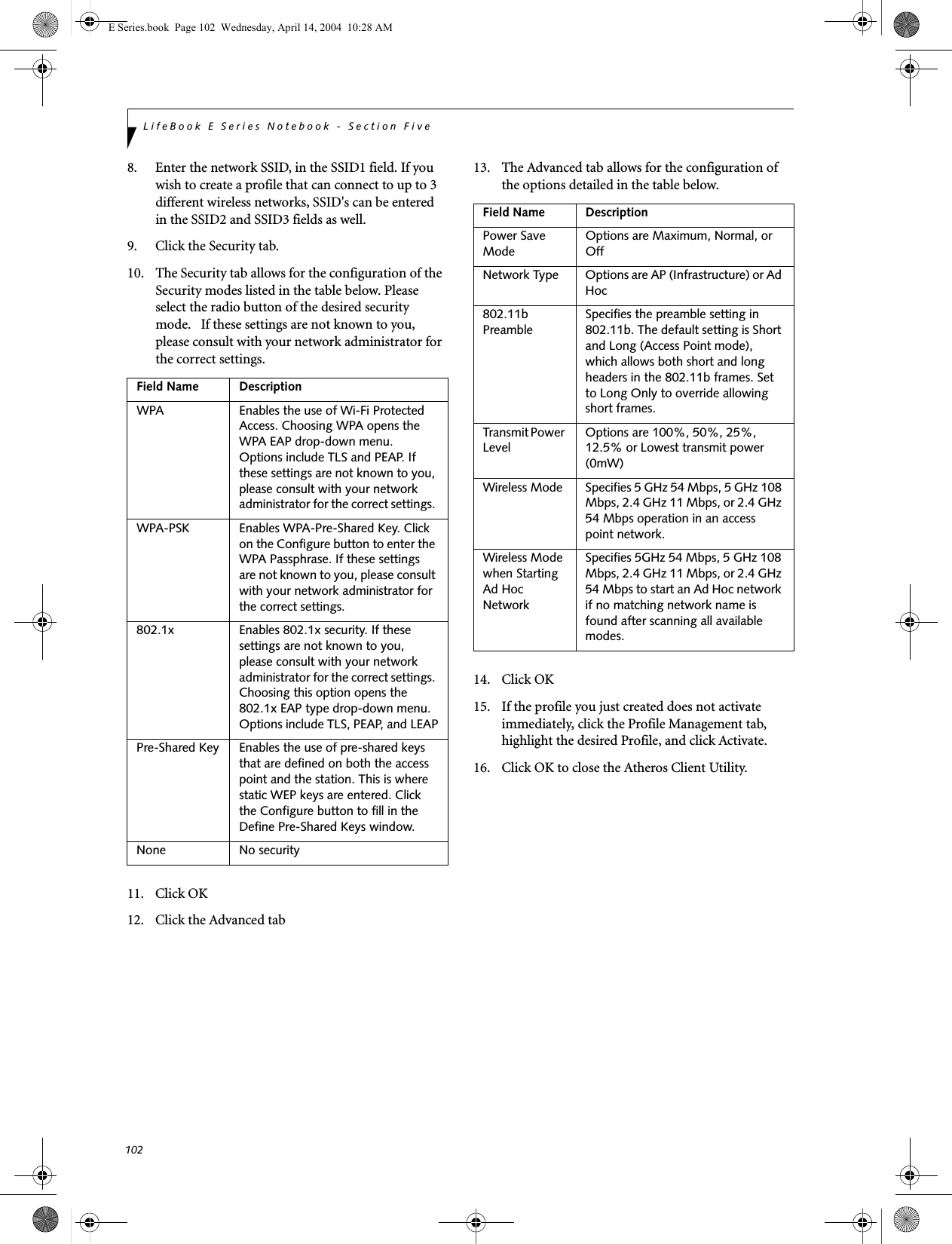
![101WIreless LAN User’s Guide 6. Click the [Add] button. The General Settings dialog displays. 7. From the General page, click the Networks tab. 8. Click the [Add] button. The General Settings dialog displays. 9. Enter a profile name in the Profile Name field. 10. Enter the network SSID, in the Network Name (SSID) field. 11. Click Infrastructure or Ad Hoc for the operating mode. 12. The Mandatory AP option is only used if Infra-structure mode is selected. Use this option to con-nect to a specific access point. Click the Mandatory AP button, enter the MAC address for the access point. Click OK to save the setting and return to the General Settings page. 13. If you are using Cisco CCX, click the Enable Cisco Client eXtentions option to enable Cisco CKIP data encryption on the Security Settings page. If you have checked the Cisco's "Mixed-Cell" box in the Advanced Setting, this option must also be checked. 14. Click Next.15. Click the Security tab16. Select Open, Shared, WPA, or WPA-PSK in the Network Authentication options. 17. Select either None, WEP, CKIP (if Enable Cisco Cli-ent eXtentions is enabled on the General Settings page), or TKIP for the data encryption. 18. If WEP is selected, select either 64 or 128-bit for the Encryption Level. 19. Select the key index 1, 2, 3 or 4. 20. Enter the WEP key if required. If your network does not employ a 802.1x/EAP security mechanism, please skip to step 24.21. Click the 802.1x Enabled checkbox to enable the 802.1x security option. Please contact your network administrator if configuration of this setting is required.22. Select the appropriate 802.1x/EAP Type. Please contact your network administrator if configura-tion of this setting is required.23. After selecting your authentication type, click the Configure button to open the Settings dialog. Enter the user name and password of the user you have created on the authentication server. The user name and password do not have to be the same as name and password of your current Windows user login. The "Server Identity" can be use the default setting. The "Client Certificate" should be the one obtained from your RADIUS server or other certifi-cation server. 24. Click Close to save the settings. 25. From the General settings page, click the new pro-file name shown in the Profile List. Use the up and down arrows to position the priority of the new profile in the priority list. 26. Click the Advanced button to set the network con-nection preferences. 27. Click the Connect button to connect to the net-work. 28. Click OK to close the Intel(R) PROSet for Wireless utilityCONFIGURATION USING ATHEROS CLIENT UTILITY SOFTWAREThis section explains the procedure to properly configure the WLAN device using the Atheros Client Utility. Pre-defined parameters will be required for this procedure. Please consult with your network adminis-trator for these parameters:Network Name - Also known as the SSIDNetwork Key (WEP) - Required if using static WEP keys. Authentication Type - Open, Shared, WPA, or WPA-PSKProcedure1. Activate the WLAN device using either the Wireless On/Off Switch or the Atheros Client Utility2. Click the [Start] button first and then [Control Panel].3. If the Control Panel is in Category view, switch to Classic view by clicking "Switch to Classic View" which can be found in the left frame of the Control Panel window. 4. Double-click the icon [Atheros Client Utility] to execute the Atheros Client Utility.5. From the Current Status page, click the Profile Management tab. 6. If this is your first time using this utility, highlight the profile [Default] and Click the [Modify] button, otherwise Click the [New] button. The General Set-tings dialog displays. 7. From the General page, enter a profile name in the Profile Name field. E Series.book Page 101 Wednesday, April 14, 2004 10:28 AM](https://usermanual.wiki/Fujitsu-Client-Computing/WB0014.USERS-MANUAL-2/User-Guide-478054-Page-50.png)
![103WIreless LAN User’s Guide CONNECTION TO THE NETWORKThis section explains connection to the network.If there is an administrator of the network, contact the network administrator for data settings.Setting the networkPerform the “Setting TCP/IP” and “Confirming the computer and work group names” operations required for network connection.Setting TCP/IP1. Click the [Start] button first and then [Control Panel].2. If the Control Panel is in Category view, switch to Classic view by clicking “Switch to Classic View” under Control Panel the left frame. (If you are already in Classic view, “Switch to Category View” will be displayed.) 3. Double-click [Network Connections]. A list of cur-rently installed networks will be displayed.4. Right-click [Wireless Network Connection] in the list, and then click [Properties] in the menu dis-played. The [Wireless Network Connection Proper-ties] window will be displayed.5. Click the [General] tab if it is not already selected.6. Click [Internet Protocol (TCP/IP] and then click [Properties]. The [Internet Protocol (TCP/IP) Properties] window will be displayed.7. Set the IP address as follows:■For ad hoc connection: Select [Use the following IP address:] and then enter data for [IP address] and [Subnet mask]. See page 109 for IP address setting.■For access point (infrastructure) connection: If your network uses DHCP, select [Obtain an IP address automatically] and [Obtain DNS server address automatically]. If your network uses static IP addresses, consult with your network adminis-trator for the correct IP address settings.8. Click the [OK] button. Processing will return to the [Wireless Network Connection Properties] window.9. Click the [OK] button.10. Close the [Network Connection] window. Following this operation, confirm the names of the computer and the workgroup as follows.Confirming the computer and work group names1. Click the [Start] button, then [Control Panel].2. If the Control Panel is in Category view, switch to Classic view by clicking “Switch to Classic View” under Control Panel the left frame. (If you are already in Classic view, “Switch to Category View” will be displayed.) 3. Double-click the [System] icon. The [System Prop-erties] window will be displayed.4. Click the [Computer Name] tab.5. Confirm the settings of [Full computer name:] and [Workgroup:].a. The setting of [Full computer name:] denotes the name for identifying the computer. Any name can be assigned for each personal computer. Enter the desired name in less than 15 ASCII character code format. Identifiability can be enhanced by entering the model number, the user name, and other factors.b. [Workgroup name] is the group name of the network. Enter the desired name in less than 15 ASCII character code format.For ad hoc connection: Assign the same network name to all personal computers existing on the network.For access point (infrastructure) connection: Assign the name of the work group to be accessed.6. Click the [OK] button. If a message is displayed that requests you to restart the personal computer, click [Yes] to restart the computer.Setting the sharing functionSet the sharing function to make file and/or printer sharing with other network-connected personal computers valid.This operation is not required unless the sharing func-tion is to be used.To change the setting of the IP address, you need to be logged in from Windows as an administrator.To modify the computer name and/or the work group name, you need to be logged in from Windows as an administrator.To change the name, click [Change] and then proceed in accordance with the instruction messages displayed on the screen.E Series.book Page 103 Wednesday, April 14, 2004 10:28 AM](https://usermanual.wiki/Fujitsu-Client-Computing/WB0014.USERS-MANUAL-2/User-Guide-478054-Page-52.png)
![104LifeBook E Series Notebook - Section FiveThe folder and printer for which the sharing function has been set will be usable from any personal computer present on the network.Setting the Microsoft network-sharing service1. Click the [Start] button first and then [Control Panel]. 2. If the Control Panel is in Category view, switch to Classic view by clicking “Switch to Classic View” under Control Panel the left frame. (If you are already in Classic view, “Switch to Category View” will be displayed.) 3. Double-click [Network Connections]. A list of cur-rently installed networks will be displayed.4. Right-click [Wireless Network Connection] in the list, and then click [Properties] in the menu dis-played. The [Wireless Network Connection Proper-ties] window will be displayed.5. If [File and Printer Sharing for Microsoft Net-works] is displayed, proceed to step 6. If [File and Printer Sharing for Microsoft Networks] is not dis-played, skip to step 7.6. Make sure that the [File and Printer Sharing for Microsoft Networks] check box is checked, and then click the [OK] button. Skip to “Setting file-sharing function”.7. Click [Install]. The [Select Network Component Type] window will be displayed.8. Click [Service], then click the [Add] button. The [Select Network Service] window will be displayed.9. Click [File and Printer Sharing for Microsoft Net-works] and then click the [OK] button. Processing will return to the [Wireless Network Connection Properties] window, and [File and Printer Sharing for Microsoft Networks] will be added to the list.10. Click the [Close] button.Setting the file-sharing functionThe procedure for setting the file-sharing function follows, with the “work” folder in drive C: as an example.1. Click the [Start] button first and then [My Com-puter]. 2. Double-click [Local disk (C:)].3. Right-click the “work” folder (or whichever folder you want to share), and then click [Sharing and Security...] in the menu displayed. The [Folder Name Properties] window will be displayed.4. Click [Sharing] if it isn’t already selected.5. Click the link stating “If you understand the secu-rity risks, but want to share files without running the wizard, click here”.6. Click “Just enable file sharing” and click [OK].7. Check the [Share this folder on the network] check box.8. Click the [OK] button. The folder will be set as a sharable folder, and the display of the icon for the “work.” folder will change.Setting the printer-sharing function1. Click the [Start] button first and then [Printers and FAX]. A list of connected printers will be displayed.2. Right-click the printer for which the sharing func-tion is to be set, and then click [Sharing] in the menu displayed. The property window correspond-ing to the selected printer will be displayed.To share a file and/or the connected printer, you need to be logged in as an administrator. Setting the file-sharing function for the file which has been used to execute Network Setup Wizard is suggested on the screen. For the wireless LAN, however, since security is guaranteed by entry of the network name (SSID) and the network key, the steps to be taken to set the file-sharing function easily without using Network Setup Wizard are given below.To specify the corresponding folder as a read-only folder, select the [Read only] checkbox under the General tab.Setting the printer-sharing function when Network Setup Wizard has been executed is suggested on the screen. For the wireless LAN, however, since security is guaranteed by entry of the network name (SSID) and the network key, the steps to be taken to set the printer-sharing function without using Network Setup Wizard are laid down below.E Series.book Page 104 Wednesday, April 14, 2004 10:28 AM](https://usermanual.wiki/Fujitsu-Client-Computing/WB0014.USERS-MANUAL-2/User-Guide-478054-Page-53.png)
![105WIreless LAN User’s Guide 3. Click the [Sharing] tab.4. Click [Share this printer].5. Enter the sharing printer name in [Share name].6. Click the [OK] button. Confirming connectionAfter you have finished the network setup operations, access the folder whose sharing has been set for other personal computers. Also, confirm the status of the radio waves in case of trouble such as a network connection failure.Connecting your personal computer to another personal computer1. Click [Start] first and then [My Computer]. The [My Computer] window will be displayed in the left frame.2. Click [My Network Places] in the “Other Places” list. The window [My Network Places] will be dis-played.3. Click [View workgroup computers] under Network Tasks in the left frame.4. Double-click the personal computer to which your personal computer is to be connected. The folder that was specified in “Setting the file-sharing func-tion” on page 104 will be displayed.5. Double-click the folder to be accessed.Confirming the status of the radio1. Right-click the Intel PRO Wireless icon in the lower right corner of the screen.2. Click [Open Intel PROSet for Wireless]. The Intel PROSet for Wireless window opens.3. Contained within the General tab and the Details section (accessed by pressing the [Details] button), you will find the current operating status of the radio. (When the radio is turned off or the com-puter is not yet connected, some of the conditions will not be displayed.)■Network Name (SSID)Displays the Network Name (SSID) currently used by the radio.■Profile NameThe current configuration profile is displayed.■ModeDisplays the current operating mode. [Infra-structure (AP)] or [Ad Hoc] will be displayed.■SecurityDisplays the current security status of the profile being used:None: No encryption used.WEP: WEP encryption algorithm used.CKIP: WEP encryption algorithm used.TKIP: WEP encryption algorithm used.■SpeedDisplays the highest data rate of the associated access point in mega-bits-per-second (Mbps) until data transfer occurs.802.11g: 1, 2, 5.5, 6, 9, 11, 12, 18, 24, 36, 48, or 54. 802.11b: 1, 2, 5.5, or 11.■Band (Frequency)Displays the current band and frequency being used. Displays Out of Range if no band and frequency is displayed. Displays:802.11g (2.4 GHz) or 802.11b (2.4 GHz)■ChannelDisplays the current transmit and receive channel being used.■802.1x ProtocolDisplays Enabled if the profile uses 802.1x authentication. Default is Disabled.In the case of access point (infrastructure) connection, enter the necessary data for the access point before confirming connection. Refer to the manual of the access point for the access point setup procedure.E Series.book Page 105 Wednesday, April 14, 2004 10:28 AM](https://usermanual.wiki/Fujitsu-Client-Computing/WB0014.USERS-MANUAL-2/User-Guide-478054-Page-54.png)
![109WIreless LAN User’s Guide IP address informationIf IP address is unknown, set IP address as follows:If you have an access point (DHCP server) on the network, set the IP address as follows:[Obtain an IP address automatically]If the IP address is already assigned to the computer in the network, ask the network administrator to check the IP address to be set for the computer.If no access point is found in the network:An IP address is expressed with four values in the range between 1 and 255.Set the each computer as follows: The value in paren-theses is a subnet mask.<Example>Computer A: 192.168.100.2 (255.255.255.0)Computer B: 192.168.100.3 (255.255.255.0)Computer C: 192.168.100.4 (255.255.255.0)::Computer X: 192.168.100.254 (255.255.255.0)IP addressing is much more complicated than can be briefly explained in this document. You are advised to consult with your network administrator for additional information.A DHCP server is a server that automatically assigns IP addresses to computers or other devices in the network. There is no DHCP server for the AdHoc network.E Series.book Page 109 Wednesday, April 14, 2004 10:28 AM](https://usermanual.wiki/Fujitsu-Client-Computing/WB0014.USERS-MANUAL-2/User-Guide-478054-Page-58.png)
![111WIreless LAN User’s Guide Using the Bluetooth DeviceThe Integrated Bluetooth module (UGXZ5-102A) is an optional device available for Fujitsu mobile computers. WHAT IS BLUETOOTHBluetooth technology is designed as a short-range wire-less link between mobile devices, such as laptop computers, phones, printers, and cameras. Bluetooth technology is used to create Personal Area Networks (PANs) between devices in short-range of each other. WHERE TO FIND INFORMATIONABOUT BLUETOOTHThe Bluetooth module contains a robust Help user’s guide to assist you in learning about operation of the Bluetooth device.To access the Help file, click [Start] -> All Programs, and click on Toshiba. Select Bluetooth, then select User’s Guide.For additional information about Bluetooth Technology, visit the Bluetooth Web site at: www.bluetooth.com.FCC Radiation Exposure StatementThis equipment complies with FCC radiation exposure limits set forth for an uncontrolled environment. This equipment should be installed and operated with a minimum distance of 20 centimeters between the Wire-less LAN/Bluetooth antenna (located on the top edge of the LCD screen) and your body. The transmitters in this device must not be co-located or operated in conjunction with any other antenna or transmitter.Canadian NoticeTo prevent radio interference to the licensed service, this device is intended to be operated indoors and away from windows to provide maximum shielding. Equipment (or its transmit antenna) that is installed outdoors is subject to licensing.WarrantyUsers are not authorized to modify this product. Any modifications invalidate the warranty.This equipment may not be modified, altered, or changed in any way without signed written permission from Fujitsu. Unauthorized modification will void the equipment authorization from the FCC and Industry Canada and the warranty.E Series.book Page 111 Wednesday, April 14, 2004 10:28 AM](https://usermanual.wiki/Fujitsu-Client-Computing/WB0014.USERS-MANUAL-2/User-Guide-478054-Page-60.png)