Fujitsu Client Computing WB0042 STYLISTIC ST SERIES W/ WM3945ABG 11 ABG WLAN & BT User Manual USERS MANUAL
Fujitsu Limited STYLISTIC ST SERIES W/ WM3945ABG 11 ABG WLAN & BT USERS MANUAL
UserManual.wiki
>
Fujitsu Client Computing
>
WB0042 User Manual
USERS MANUAL
Navigation menu
Upload a User Manual
Namespaces
Wiki Guide
HTML
PDF
Info
Views
User Manual
Discussion / Help
Navigation


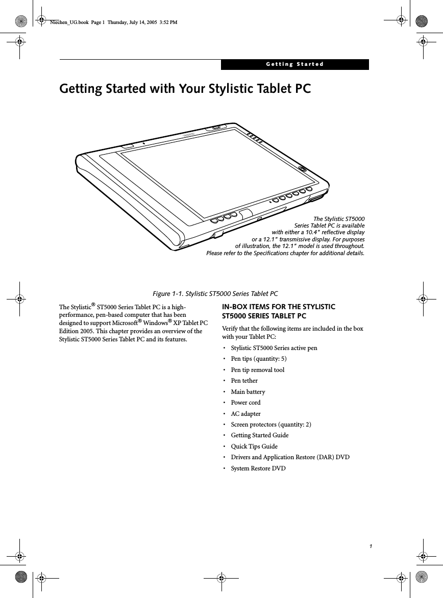
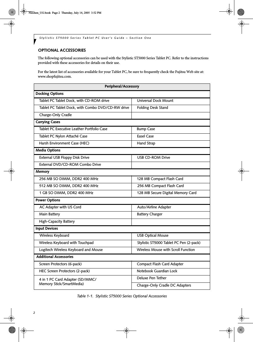
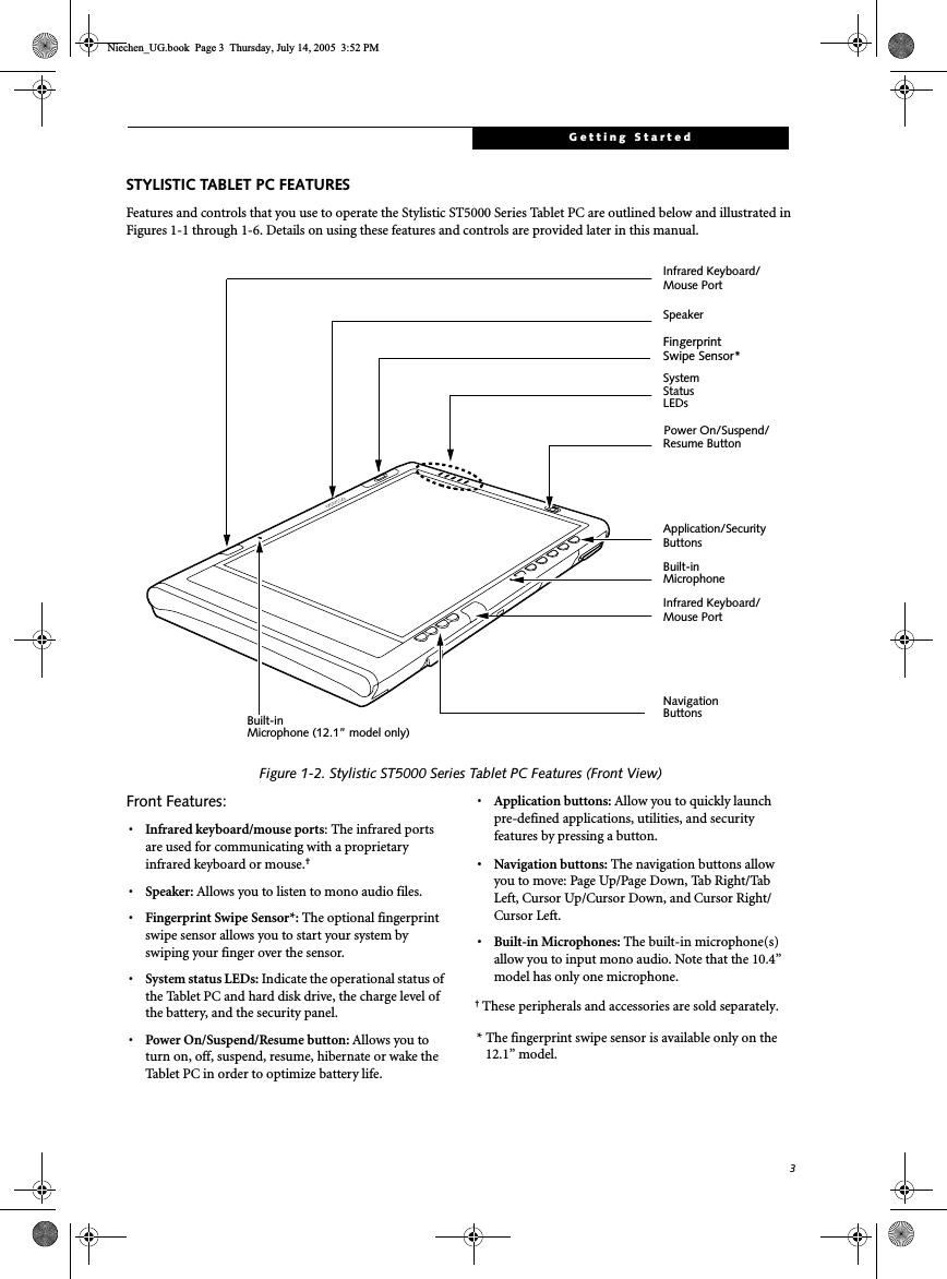
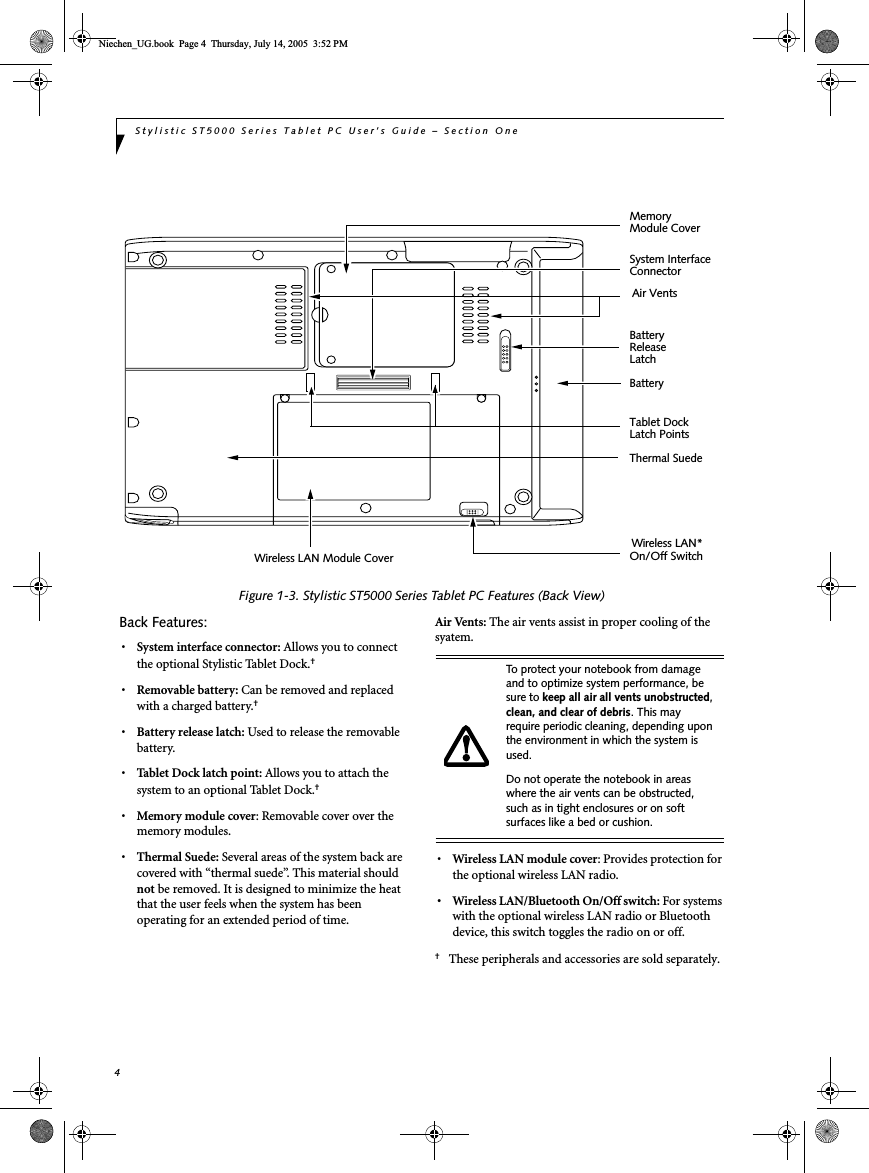
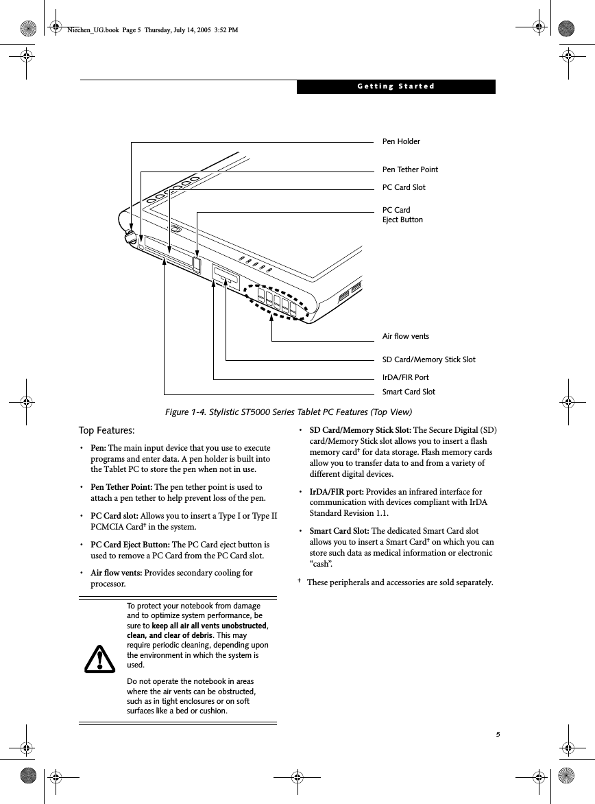
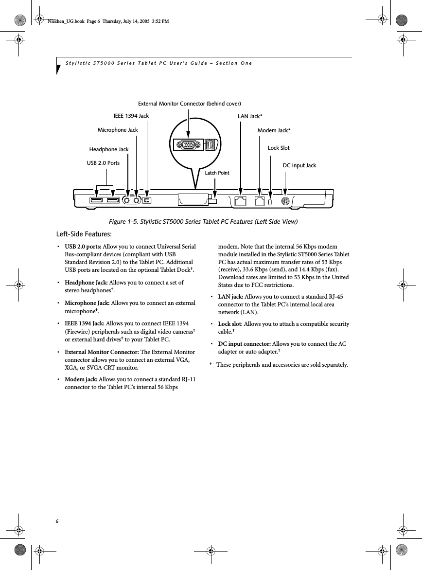
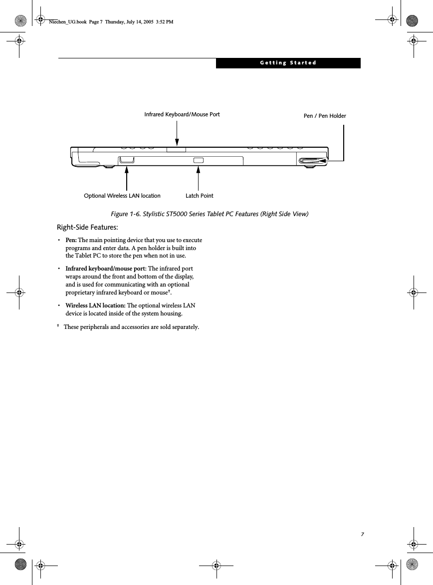
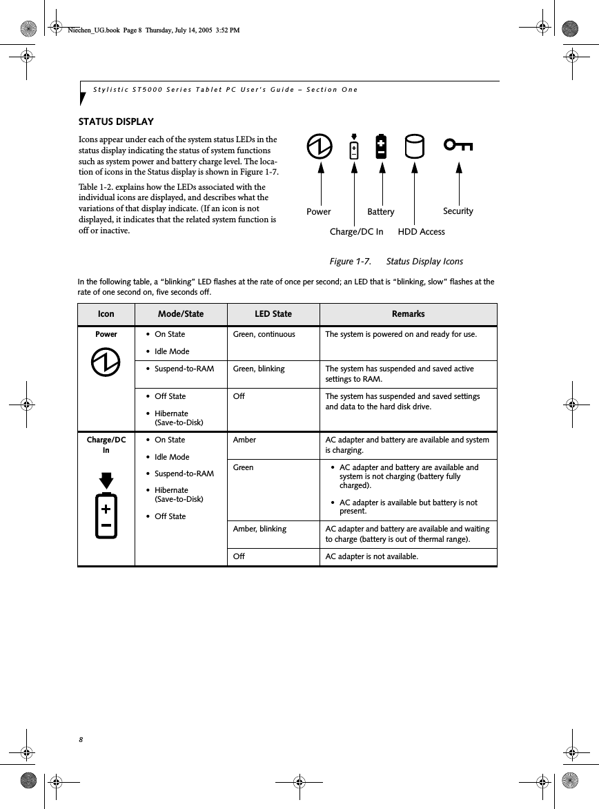
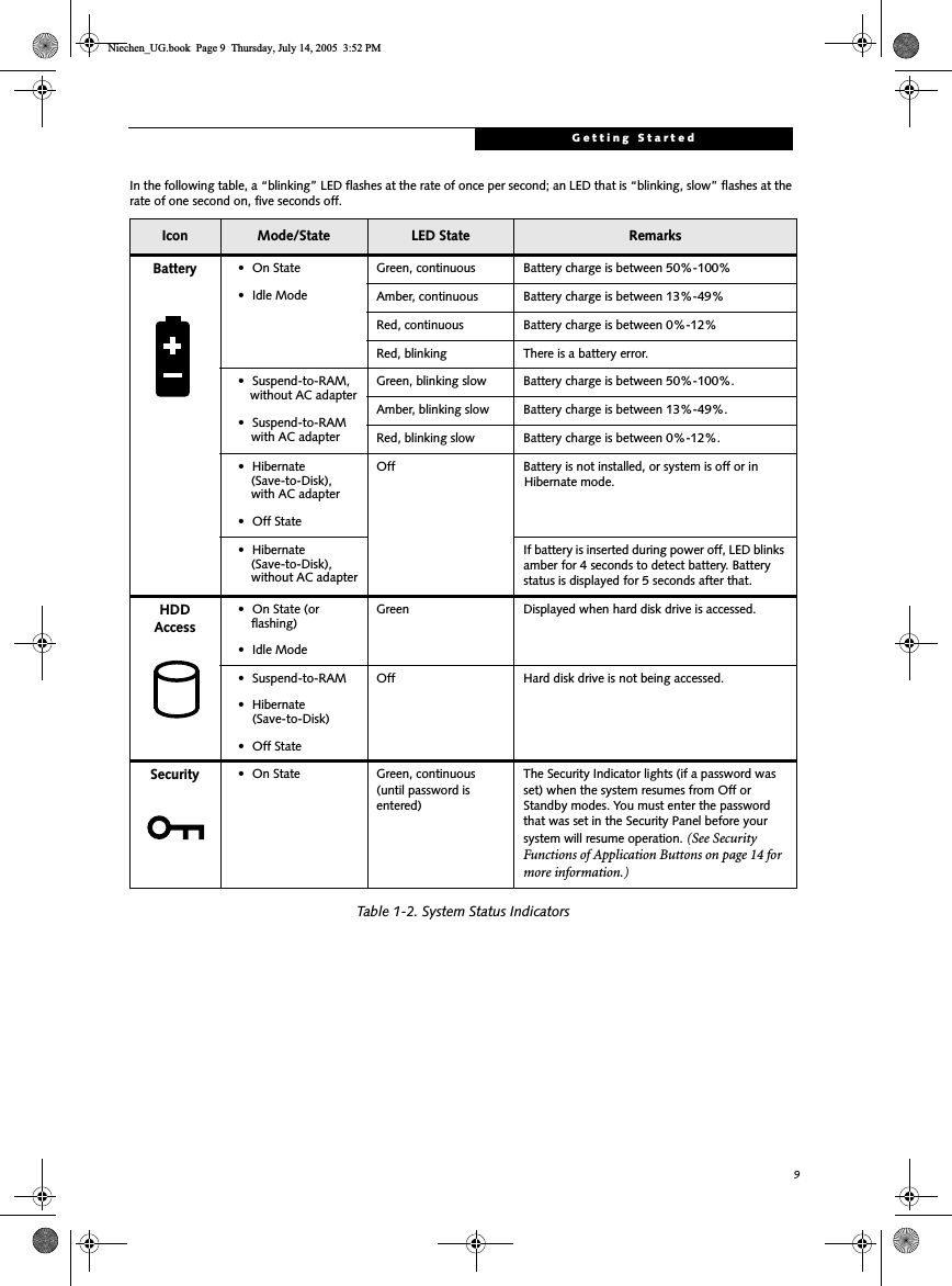
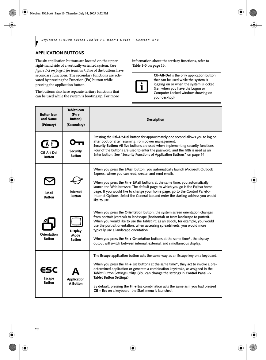
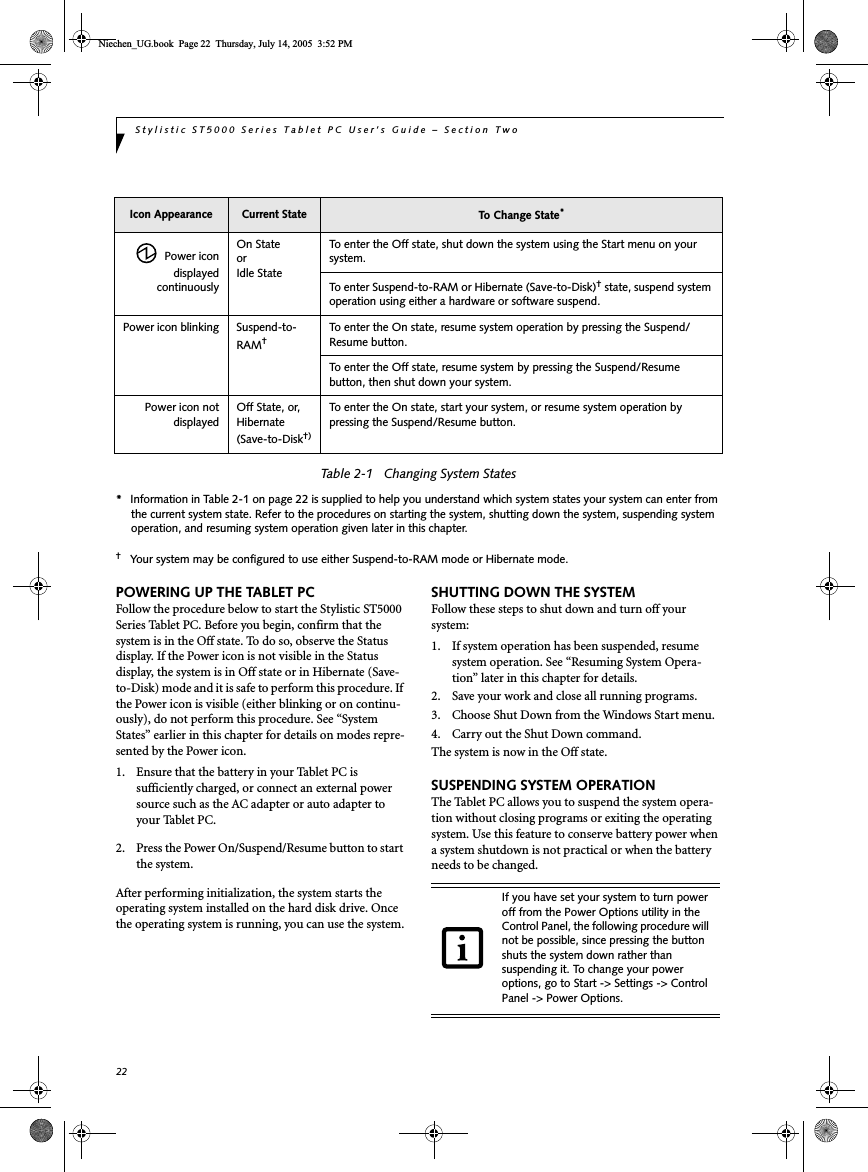
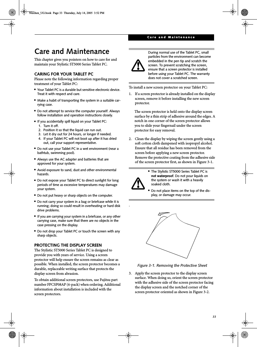
![PrefacePrefaceABOUT THIS GUIDEThe Stylistic ST5000 Series Tablet PC is a high-performance, pen-based computer that has been designed to support MicrosoftWindows XP Tablet PC Edition.This manual explains how to operate your Fujitsu Stylistic ST5000 Series Tablet PC hardware and built-in system software. The Stylistic ST5000 Series Tablet PC is a completely self-contained unit with an active-matrix (TFT) color LCD display and an active digitizer. It has a powerful interface that enables it to support a variety of optional features. Conventions Used in the GuideKeyboard keys appear in brackets. Example: [Fn], [F1], [ESC], [ENTER] and [CTRL].Pages with additional information about a specific topic are cross-referenced within the text.Example: (See page xx.)On screen buttons or menu items appear in boldExample: Click OK to restart your Tablet PC.DOS commands you enter appear in Courier type. Example: Shut down the computer?FUJITSU CONTACT INFORMATIONService and SupportYou can contact Fujitsu Service and Support in the following ways:■Toll free: 1-800-8Fujitsu (1-800-838-5487)■E-mail: 8fujitsu@us.fujitsu.com■Web site: http://www.computers.us.fujitsu.com/supportBefore you place the call, you should have the following information ready so the customer support representative can provide you with the fastest possible solution:■Product name■Product configuration number■Product serial number■Purchase date■Conditions under which the problem occurred■Any error messages that have occurred■Type of device connected, if anyFujitsu OnlineYou can go directly to the online Fujitsu product catalog for your Stylistic Tablet PC by clicking on the Fujitsu Weblinks -> LifeBook Accessories web site link, located in the Windows Start -> All Programs menu.You can also reach Fujitsu Service and Support on-line by clicking on the Fujitsu Weblinks -> Fujitsu Service and Support Web site link, located in the Service and Support Software folder of the Windows Start -> All Programs menu..LIMITED WARRANTY INFORMATIONYour Stylistic ST5000 Series Tablet PC is backed by an International Limited Warranty. Check the service kit that came with your system for warranty terms and conditions.The information icon highlights information that will enhance your understanding of the subject material.The caution icon highlights information that is important to the safe operation of your computer, or to the integrity of your files. Please read all caution information carefully.The warning icon highlights information that can be hazardous to either you, your computer, or your files. Please read all warning information carefully.You must have an active internet connec-tion to use the online URL links.Niechen_UG.book Page v Thursday, July 14, 2005 3:52 PM](https://usermanual.wiki/Fujitsu-Client-Computing/WB0042/User-Guide-724789-Page-8.png)


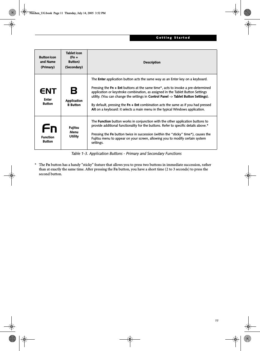
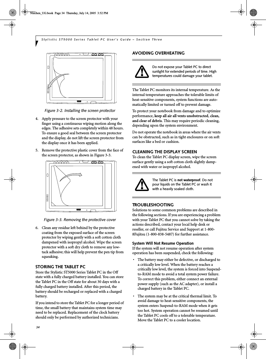
![13Getting StartedTERTIARY FUNCTIONS OF APPLICATION AND NAVIGATION BUTTONSWhile you are booting up your system, the Application Buttons and Navigation buttons can be used for entering and navigating through the Basic Input-Output System (BIOS), and for invoking the Advanced Options Menu, where you can enter different modes (such as Safe Mode).The BIOS is a program and a set of parameters that are stored in ROM, which tests and operates your Tablet PC from when you turn it on until it loads your installed operating system from disk. Information from the BIOS is transferred to the operating system to provide it with information on the configuration and status of the hard-ware.The system is booting up while the Fujitsu logo is displayed immediately after turning on the system. The table below indicates how the buttons act while the system is booting up and while you are in the BIOS.Table 1-5. Tertiary Functions of Application and Navigation ButtonsButtons/icons Purpose (when pressed while the system is booting up)Ctl-Alt-DelButtonPressing the Ctl-Alt-Del button while the system is booting up takes you into BIOS setup. This is the same as if you had tapped [F2] on a keyboard.EMail ButtonPressing the EMail button while the system is booting up opens the Boot Options menu. This is the same as if you had tapped [F12] on a keyboard.Orientation ButtonPressing the Orientation button while the BIOS setup screen is open causes the selected item (if applicable) to change to the next item. Pressing this is the same as tapping the spacebar on a keyboard.Escape ButtonPressing the Esc button while the BIOS is open acts to escape from the BIOS. This is the same as if you had tapped [Esc] on a keyboard.Enter ButtonPressing the Ent button while the BIOS is open acts the same as the [Ent] button on a keyboard. Function ButtonPressing the Fn button while the system is displaying the operating system boot menu, opens the Advanced Operating System Options menu. This menu allows you to enter different operating system modes (such as Safe Mode). Pressing this button is the same as if you had tapped [F8] on a keyboard.Pressing the top half of the upper navigation button while the BIOS setup screen is open causes the cursor in the BIOS setup screen to move up. This is the same as if you had tapped Arrow Up on a keyboard. This feature is also functional in the operating system boot menu.Pressing the bottom half of the upper navigation button while the BIOS setup screen is open causes the cursor in the BIOS setup screen to move down. This is the same as if you had tapped Arrow Down on a keyboard. This feature is also functional in the operating system boot menu.Pressing the top half of the lower navigation button while the BIOS setup screen is open causes the cursor in the BIOS setup screen to move right. This is the same as if you had tapped Arrow Right on a keyboard.Pressing the bottom half of the lower navigation button while the BIOS setup screen is open causes the cursor in the BIOS setup screen to move left. This is the same as if you had tapped Arrow Left on a keyboard.Niechen_UG.book Page 13 Thursday, July 14, 2005 3:52 PM](https://usermanual.wiki/Fujitsu-Client-Computing/WB0042/User-Guide-724789-Page-24.png)
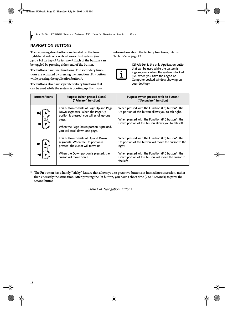
![14Stylistic ST5000 Series Tablet PC User’s Guide – Section OneSECURITY FUNCTIONS OF APPLICATION BUTTONSFive buttons are used when implementing security functions. Four of the buttons are used to enter the password, and the fifth is used as an Enter button. Instructions for using the security feature follow the table.Table 1-6. Security Functions of Application ButtonsSETTING UP THE SECURITY PANELWhen you receive your Tablet PC, the security panel application is pre-installed without any passwords. The following sections provide detailed information on your security panel, how to set, change or remove passwords.Numbered ButtonsUse these buttons to enter your password.(Figure 1-6)Enter ButtonAfter entering the button strokes, push this button to enter the password into the Tablet PC. (Figure 1-6)PASSWORDSThe user and supervisor password may be set on this Tablet PC. A supervisor password is typically the same for all Tablet PC’s and notebooks in a work group, office, or company to allow for system management. Individual computers in a group environment should not use a common password. A password consists of one to five button strokes plus the enter button. A valid stroke consists of pushing one or up to four buttons simulta-neously. The following are valid button strokes: ■Pushing [4] by itself■Pushing [2] and [3] at the same time■Pushing [1], [2], and [4] at the same time■Pushing [1], [2], [3], and [4] at the same timeThe following are valid passwords. The numbers within braces ({ }) are button strokes using more than one button. ■{[2]+[3]}, [1], [Enter]■[4], [enter]■{[1]+[3]}, {[2]+[3]+[4]}, [1], [4], [2], [Enter]Setting PasswordsWhen shipped from the factory, no passwords are set. You have a choice of having no password or setting a supervisor and user password. You must set the super-visor password before the user password.Button Icons Security Icons Security PurposeCtl-Alt-Del ButtonSecurity Enter ButtonEMail Button1Security Button 1Orientation Button2Security Button 2Escape Button3Security Button 3Enter Button4Security Button 4■The purpose of supervisor password is to be able to bypass the user password in case the user password is forgotten. The supervisor password alone will not lock the system.■You must set the supervisor and user passwords for the security panel to work.Niechen_UG.book Page 14 Thursday, July 14, 2005 3:52 PM](https://usermanual.wiki/Fujitsu-Client-Computing/WB0042/User-Guide-724789-Page-25.png)
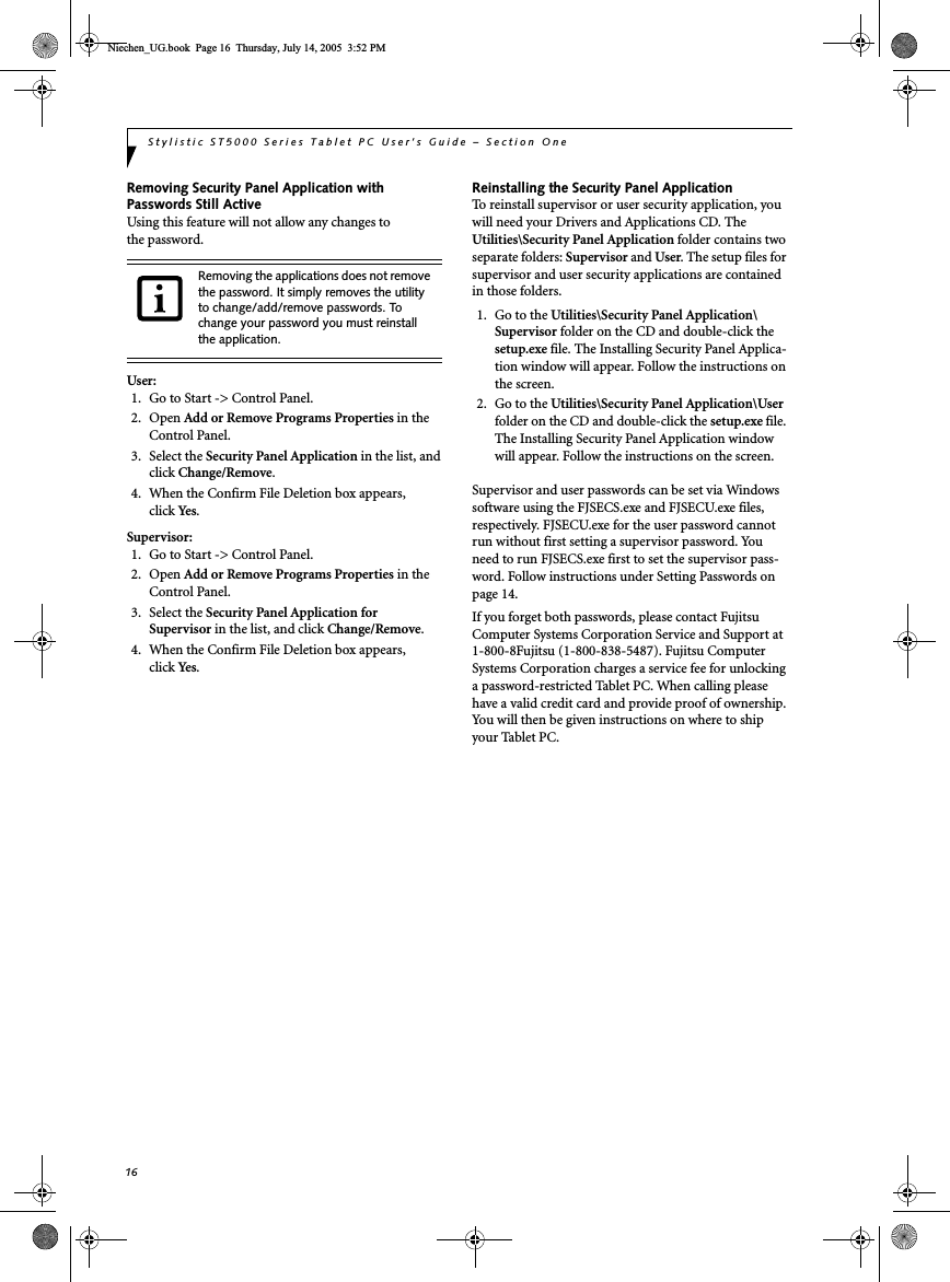
![15Getting StartedSetting Supervisor PasswordYou must have set a supervisor password before setting any user passwords. The supervisor password can bypass the user password.1. Go to the Start menu.2. Click on Run.3. Type in:C:\Program Files\Fujitsu\Security Panel Application\Supervisor\ FJSECS.EXE, then press [Enter]4. Follow the on-screen instructions to set theSupervisor password.Setting User Password1 Go to the Start menu.2. Click on All Programs.3. Click on Security Panel Application -> Security Panel Application.4. Follow the on-screen instructions to set theuser password.USING YOUR SECURITY PANELThe security lock feature is in effect both when the system resumes from Off, Standby, or Hibernation state. You always need to push the Security Panel buttons to input the user password. Your system will not begin the boot sequence until you enter your supervisor/user password.From Off State1. Turn on your system.2. When the Security Indicator flashes, enter the pass-word and press Enter button.For example, if the password is 22222, first press Button 2 five times and press the Enter button. The Tablet PC will boot to normal operation.From Standby/Hibernation State1. Press your Suspend/Resume button.2. When the Security Indicator flashes, enter the pass-word and press Enter button.The Tablet PC should resume normal operation.Incorrect Password EntryIf an invalid supervisor or user password is entered three times in succession, the system will “beep” for about one minute. If a valid password is entered within a minute (while system beeps), the beeping will stop and the Tablet PC will resume normal operation. If no password is entered or an invalid password is entered while the system beeps, the system will return to its previous locked state (standby or off) and the Security Indicator will go off. To reactivate the Tablet PC after a password failure, you must press the Suspend/Resume button, then enter a correct password.PRECAUTIONSLow Battery OperationsIf your Tablet PC has a low battery, pushing the suspend/resume button does not unlock the Tablet PC. To resume normal operation, first attach a power supply to the system. Then you may unlock the Tablet PC.UNINSTALLING THE SECURITY PANEL APPLICATIONYou have two options when uninstalling the securitypanel application:■Remove passwords and uninstall the security panel application software. This will disable all security features.■Uninstall the security panel application with password still active. This will not allow any changes to the password. Uninstalling the Security Panel Application SoftwareRemove passwords when User wants no password protec-tion whatsoever and doesn’t want to give anybody the utility to set a password on their computer. In this case, if passwords (supervisor, user, or both) are set, the pass-words must first be cleared BEFORE removing the appli-cation. To clear passwords, follow same procedure in SETTING PASSWORD CODES except this time, select REMOVE, enter current password then click Next. When asked to confirm select Ye s .You may change or remove the supervisor or user password by repeating the steps defined above.Remember the user password you specified on the Security Panel Application. If you forget the password you will not be able to use your computer. The supervisor pass-word can override the user password.Niechen_UG.book Page 15 Thursday, July 14, 2005 3:52 PM](https://usermanual.wiki/Fujitsu-Client-Computing/WB0042/User-Guide-724789-Page-26.png)

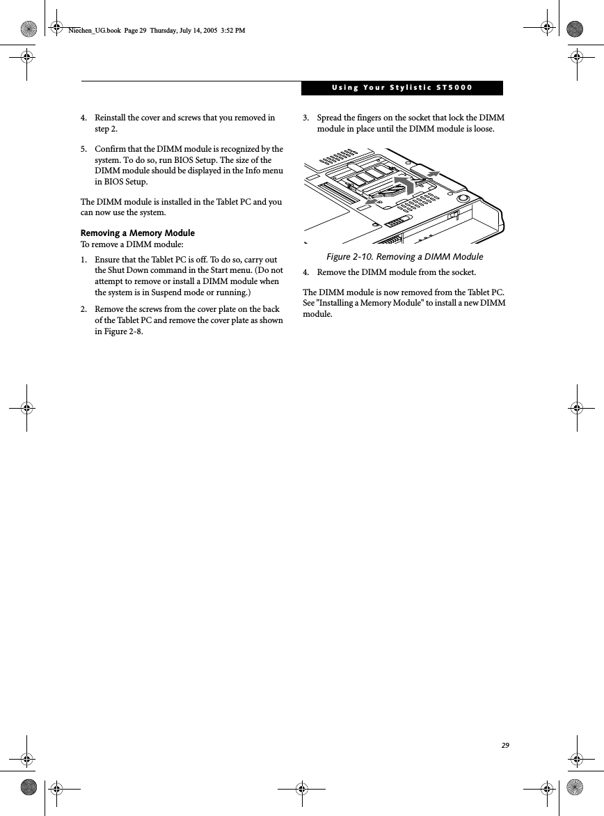
![28Stylistic ST5000 Series Tablet PC User’s Guide – Section TwoRemoving A Memory Stick/SD CardTo remove a Memory Stick/SD Card, follow these steps:Push the Memory Stick or SD Card in until it unlatches. It will then eject from the slot for removalPC CARD SLOTThe Stylistic ST5000 Series Tablet PC Card slot allows you to insert a Type I or Type II PCMCIA Card. Inserting a PC CardTo insert a PC card, position the side with the arrow facing up (i.e., when looking at the tablet’s display side, the arrow on the card should be visible.) Slide the card into the PC Card slot, and press it firmly to ensure proper seating. (See Figure 2-6 for location)If you need assistance inserting a PC Card in the Stylistic ST5000 Series Tablet PC, contact your corporate help desk or reseller.Figure 2-6. Inserting a PC CardRemoving a PC CardTo remove a PC Card, first click the Safely Remove Hardware icon in the system tray in the bottom right-hand corner of the display. Select PC Card from the list, and click [Stop]. Press the PC Card eject button so that it pops out. Once the button has popped out, press it firmly to eject the card. (See Figure 2-7 for location)Figure 2-7. Removing a PC CardREMOVING AND INSTALLING MEMORY MODULESThere are two DIMM slots in your Tablet PC. 256 MB, 512 MB, and 1 GB modules are available, so you can install a combination of up to 2 GB in the system.Installing a Memory ModuleTo install a DIMM module in the Tablet PC: 1. Ensure that the Tablet PC is off. To do so, carry out the Shut Down command in the Start menu. (Do not attempt to remove or install a DIMM module when the system is in Suspend mode or running.) 2. Remove the two screws from the cover plate on the back of the Tablet PC and remove the cover plate as shown in Figure 2-8.Figure 2-8. Accessing the Memory Slot3. Insert the DIMM module in the socket at an angle and push it down until it locks into place as shown in Figure 2-9. Note that the DIMM module is keyed to prevent it from being inserted backwards.Figure 2-9. Installing a DIMM ModuleSee your Memory Stick or SD Card manual for specific instructions on the removal of your card. Some cards may require your computer to be in Suspend Mode or Off while removing them. DIMM replacement should be performed at a static-free workstation. Do not touch connector pins, circuit boards, or other circuit components on the drive or Tablet PC. Electrostatic discharge caused by doing so can damage sensitive components.Niechen_UG.book Page 28 Thursday, July 14, 2005 3:52 PM](https://usermanual.wiki/Fujitsu-Client-Computing/WB0042/User-Guide-724789-Page-39.png)


![35Care and MaintenanceDisplay Screen Blank or Difficult to ReadIf the display screen on your Tablet PC appears blank or is unreadable, confirm that the system is running (the Power icon is displayed continuously on the Status display), and check the following: • The system brightness may be set too low, causing the screen to appear too dark. To change system brightness, press the Fn button twice to open the Fujitsu menu. Brightness can be adjusted from the menu.• The video timeout may have expired. Tap on the display screen to reactivate the display. Note that this is a normal, power-saving feature. Cursor Is Not Tracking PenIf the cursor on the screen appears to be misaligned with the pen or is not accurately tracking the pen, calibrate the pen. See “Calibrating the Pen” on page 25 for more infor-mation. Infrared Data Transfer Is Not WorkingIf you are experiencing problems transferring data over the system’s infrared interface, note the following:• Can the IrDA port on the Tablet PC “see” the IrDA port on the other device? A direct line-of-sight path must exist between the IrDA port on the Tablet PC and the IrDA port on the other device. • The distance between the two devices must not be more than 3 feet.• The viewing angle from the IrDA port on the Tablet PC must not be more than 15 degrees from a center line between the IrDA port on the Tablet PC and the IrDA port on the other device. • The device with which you are trying to communicate must be compliant with the IrDA Standard Revision 1.1 (or 1.0). • It may be necessary for both computers to be using the same network connection protocols.Tablet PC is Not Responding to the PenIf the Tablet PC does not respond to the pen, connect an external keyboard to the system to see if it responds to keyboard commands. If the system doesn’t respond to a keyboard, the application or system may have crashed, and it may be necessary to reboot the system. If the system responds to a keyboard but not to a pen, contact your local help desk or reseller, or call Fujitsu Service and Support at 1-800-8Fujitsu (1-800-838-5487) for further assistance.Speaker/Headphone Volume Too LowIf the audio volume on your Tablet PC speaker or external headphones is too low, check the following: • Ensure the speaker (or headphone output if using headphones) is enabled. To do so, open the Control Panel and double-click on the Sounds and Audio Devices icon. Select the proper tab, and increase the volume using the slider bar. (If you aren’t getting any sound, uncheck the Mute box if it is checked.) • Press the Fn button twice to open the Fujitsu menu. Volume can be adjusted from the menu.• Ensure the mute box in the system volume control (accessible from the system tray) is not set.• Ensure any volume control in your audio software is set to an audible level. Configuring Peripheral InterfacesCertain peripheral devices can be disabled during the BIOS Setup. If the peripheral interface you want to use does not appear to be working with your peripheral device, ensure that it is enabled in the BIOS. Contact your local help desk or reseller, or call Fujitsu Service and Support at 1-800-8Fujitsu (1-800-838-5487) if you need assistance using BIOS Setup.RESTORING THE PRE-INSTALLED SOFTWAREThe Drivers and Applications Restore (DAR) DVD contains sets of device drivers and Fujitsu utilities (in specific directories) that are unique to your computer configuration for use as documented below.Re-Installing Individual Drivers and Applications The Drivers and Applications CD can be used to selectively re-install drivers and/or applications that may have been un-installed or corrupted. To re-install drivers and/or applications:1. Boot up the system and insert the DAR CD after Windows has started. A Fujitsu Installer screen is displayed after the CD is inserted.2. After reading the License Agreement, click [I agree].If you have access to the internet, visit the Fujitsu Support web site at: http://www.computers.us.fujitsu.com/support to check for the most current information, drivers and hints on how to perform recovery and system updates.There may be certain free third-party applications pre-installed on your system that are not on the DAR CD. The latest versions of the applications can be downloaded from the third-party’s website.Niechen_UG.book Page 35 Thursday, July 14, 2005 3:52 PM](https://usermanual.wiki/Fujitsu-Client-Computing/WB0042/User-Guide-724789-Page-46.png)
![36Stylistic ST5000 Series Tablet PC User’s Guide – Section Three3. A window will appear containing a list of applica-tions, drivers, and utilities that you can install from the Drivers and Applications CD.4. In the list, check off all the components you want to install. If you want to install all components, click [Select All]. Clicking [Select All] will select all of the blue-coded components; you must select grey and green components separately.5. Once you have selected the components you wish to install, click [Install Selected Subsystems]; the components will be installed.6. After the components are installed, click [OK], then click [Yes] when asked if you want to reboot the system. RESTORING THE FACTORY IMAGEThe Restore Disc that came with your system contains two utilities:■The Recovery utility allows you to restore the original contents of the C: drive.■The Hard Disk Data Delete utility on this disc is used to delete all data on your hard disk and prevent it from being reused. Do not use the Hard Disk Data Delete utility unless you are absolutely certain that you want to erase your entire hard disk, including all partitions.BOOT Priority ChangeBefore restoring an image, you must first verify that your system is set up to boot from the DVD drive. To verify/change the boot-up priority (rather than booting-up from the hard drive or an external floppy disk drive), perform the following steps:1. Start your system and press the [F2] key when the Fujitsu logo appears. You will enter the BIOS Setup Utility.2. Using the arrow keys, go to the Boot menu.3. Arrow down to the Boot Device Priority submenu. Press [Enter].4. If “Optical Media Drive” or “CD-ROM Drive” is not at the top of the list, arrow down to the drive in the list, and press the space bar (or the + key) to move it to the top of the list. (The system attempts to boot from the devices in the order in which they are listed.). Note that the BIOS for some systems will indicate “CD-ROM Drive”, even when a DVD drive is connected.5. If you have an external DVD drive connected, proceed to the next step; otherwise, proceed to step 7.6. If you have an external DVD drive connected:• Select the Advanced menu in the BIOS window.• Scroll down to the USB Features submenu and press the Enter key to open it.• If Legacy USB Support is disabled, press the space bar to enable it.• Scroll down to SCSI SubClass Support and press the space bar to enable it. 7. Press [F10], then click on [Yes] to exit the BIOS Setup Utility and return to the boot process.After you have changed the boot priority, you can restore a backup image when you are booting up.Procedure1. Turn on the power to your system.2. Ensure that you have a device that can read DVDs either installed in your system or attached exter-nally to it.3. Insert the Restore Disc into the drive tray.4. Reboot your system.5. After the system reboots, follow the instructions that appear to either restore your system image or erase all data from your hard disk.The components listed are color-coded in terms of their install status. Blue indicates that the component can be installed. Green indicates that the component needs to be installed separately. Grey indicates a component that is already installed; grey items can be reinstalled, but prior to installation you will receive a reminder that the component is already installed. The Restore Disc only restores the primary hard disk drive. If you have an optional second hard disk drive installed, it will not be restored using these utilities.• The use of this disc requires that you have a device capable of reading DVDs attached to your system. If you do not have a built-in DVD player, you will need to attach an external player. For more information on available external devices, visit our Web site at: us.fujitsu.com/computers.• This disc can only be used with the system with which it was purchased.Niechen_UG.book Page 36 Thursday, July 14, 2005 3:52 PM](https://usermanual.wiki/Fujitsu-Client-Computing/WB0042/User-Guide-724789-Page-47.png)
![37Care and MaintenanceAUTOMATICALLY DOWNLOADING DRIVER UPDATESYour system has a convenient tool called the Fujitsu Driver Update (FDU) utility. With FDU, you can choose to automatically or manually go to the Fujitsu site to check for new updates for your system.The FDU icon should appear in the system tray at the bottom right of your screen (roll the cursor over the icons to find the correct one). If the FDU icon does not appear in the system tray, it can be started by going to [Start] -> All Programs, and clicking on Fujitsu Driver Update; this will create the icon automatically.To invoke the FDU menu, right-click on the FDU icon. The menu contains the following items:■Check for updates nowAllows for manual driver update search. The first time it is used, you are prompted to agree to a user agree-ment. After clicking on the icon, the FDU automati-cally connects with the Fujitsu site to check for updates and downloads them. While downloading, the icon has a red bar through it, indicating that it cannot be used while the download is in process. When the update is complete, a message appears informing you of the fact.■Enable Automatic Update NotificationsAutomatically searches for new updates on a regular basis (approximately every 3 days).■Show update historyBrings up a screen that displays a history of updates that have been made via the FDU.■About Fujitsu Driver UpdateDisplays the FDU version number and copyright information■Fujitsu Driver Update ReadmeDisplays the FDU readme.Niechen_UG.book Page 37 Thursday, July 14, 2005 3:52 PM](https://usermanual.wiki/Fujitsu-Client-Computing/WB0042/User-Guide-724789-Page-48.png)


![50Stylistic ST5000 Series Tablet PC User’s Guide – Appendix ASTOPPING TRANSMISSION To use this product inside hospitals, clinics, or airplanes, or in other places where the use of electronic equipment is regulated, stop the transmission of radio waves from the wireless LAN beforehand.Deactivation using the wireless switchThe transmission of radio waves from the wireless LAN can be stopped by setting the wireless switch to the Off position. Note that the wireless LAN On/Off switch has no effect on non-wireless LAN models.(See Figure 3 for Wireless LAN switch location.)Figure A-3. Wireless LAN On/Off SwitchDeactivation using WindowsIntel PROSet Wireless LAN:1. Click [Start] --> [(All) Programs] --> [Intel Net-work Adapters] --> [Intel(R) PROSet]. The Intel(R) PROSet window will be displayed.2. Click the General tab.3. Select [Off] for the wireless communications Switch Radio: function, and then click the [OK] button. Wireless communications on/off switching will be deactivated and the transmission of radio waves from the wireless LAN will be stopped.Atheros Wireless LAN1. Click [Start] --> [Control Panel] --> [Atheros Cli-ent Utility]. The Atheros Wireless Configuration Utility window will be displayed.2. Click the Wireless Networks tab.3. Click the [Enable Radio] box to clear it, then click the [OK] button. Wireless communications on/off switching will be deactivated and the transmission of radio waves from the wireless LAN will be stopped.STARTING TRANSMISSION To communicate using the wireless LAN function, set the computer to a status from which it can transmit, as follows:Intel PROSet Wireless LAN:1. Set the wireless switch to the On position. 2. Click [Start] --> [(All) Programs] --> [Intel Net-work Adapters] --> [Intel(R) PROSet]. The Intel(R) PROSet window will be displayed.3. Click the [General] tab if it is not already selected.4. Select [ON] for the Switch radio: function, then click [OK]. Wireless communications on/off switching will be activated and the transmission of radio waves will be restarted.Atheros Wireless LAN:1. Click the Wireless Network Connection icon in the system tray at the lower right of your screen.2. Click [Enable Radio]. The radio will be turned on.Access Point Mode: Transmission is enabled.Ad Hoc Mode: Restart your computer to enable the radio.To restart transmission, select [On] for the wireless communications Switch Radio: function, and then click the [OK] button.Wireless LANOn/OffSwitchTo restart transmission, check the [Enable Radio] checkbox to select it., then click the [OK] button.Niechen_UG.book Page 50 Thursday, July 14, 2005 3:52 PM](https://usermanual.wiki/Fujitsu-Client-Computing/WB0042/User-Guide-724789-Page-61.png)
![51Wireless LAN User’s GuideConnecting the WLANFLOW OF OPERATIONSThe wireless LAN connection procedure contained in this section is outlined below.1. Make sure the mobile computer is ready for the transmission of radio waves from the wireless LAN. For further details, see (See Starting Transmission on page 50 for more information.).2. Assign the parameters required for wireless LAN connection. (See Preparation for wireless LAN con-nection on page 51 for more information.).■Configure network name (SSID).■Configure wireless LAN security parameters as appropriate (e.g., WEP, TKIP, 802.1x/EAP).3. Perform setting operations relating to network con-nection. (See Connection to the network on page 53 for more information.)■Specify TCP/IP as the protocol, and confirm the name of the work group and other settings.■Enter the data required for file/printer sharing on the network. Perform this operation as required.■For access point (or “infrastructure”) connection, configure the wireless module with appropriate parameters required to associate to the access point network.■Verify that you are able to connect your computer to the network.PREPARATION FOR WIRELESS LAN CONNECTIONThis section explains the preparations required to use the wireless LAN when using the Windows XP Wireless Zero Configuration Tool. Configuration can also be accomplished using the wireless module (Intel or Atheros) configuration utility.Assigning parametersEnter the network name (SSID), the network key, and other data required for wireless LAN connection. If there is the administrator of the network, contact the network administrator for data settings.1. Make sure the Wireless LAN switch is switched on.2. Click the [Start] button first and then [Control Panel].3. If the Control Panel is in Category view, switch to Classic view by clicking “Switch to Classic View” under Control Panel the left frame. (If you are already in Classic view, “Switch to Category View” will be displayed instead.) 4. Double-click the Network Connections icon. A list of currently installed networks will be displayed.5. Right-click [Wireless Network Connection] in the list, and then click [Properties] in the menu dis-played. The [Wireless Network Connection Proper-ties] window will be displayed.6. Click the [Wireless Networks] tab.7. Click [Refresh], then choose the correct SSID from the [Available Networks] window. Click [Config-ure] and proceed to step 10. If the SSID of your access point does not appear in the list, click [Add]. The [Wireless Network Properties] window will be displayed.8. Select the Association tab if it is not already selected.9. Enter the information required for connection to the wireless LAN.a. Enter the network name (SSID). (i.e., Enter the name of the desired network in less than 33 ASCII characters).■To use access point (infrastructure) con-nection, refer to the access point manual for the access point-setting procedure.■You do not need to set the channel when using access point (infrastructure) mode. Channel selection is controlled by the access point. In ad hoc networks, channel selection defaults to channel 11; however, channel selection can be man-ually changed if desired. This can be accomplished only when using the client utility.If it is necessary to change the channel, change the setting of the access point. For the setting procedure, refer to the manual of the access point.Niechen_UG.book Page 51 Thursday, July 14, 2005 3:52 PM](https://usermanual.wiki/Fujitsu-Client-Computing/WB0042/User-Guide-724789-Page-62.png)
![52Stylistic ST5000 Series Tablet PC User’s Guide – Appendix AFor ad hoc connection: Assign the same network name to all the personal computers to be connected.For access point (infrastructure) connection: Assign the appropriate SSID. The SSID must be identical to the SSID of the access point. Refer to the access point manual, or contact your network administrator.b. For ad hoc connection, check the following field. For access point (infrastructure) connection,clear the check mark for the following field:[This is a computer-to-computer (ad hoc) net-work; wireless access points are not used.]10. Choose the appropriate Network Authentication type. Options are Open, Shared, WPA, or WPA-PSK. Please contact your network administrator for the correct setting.11. Choose the Data Encryption type. Options are WEP, TKIP, or AES. The latter two encryption methods are available only when the Network Authentication scheme is WPA or WPA-PSK. WEP, TKIP, and AES are different methods used to encrypt communications data. Proceed to Step 11a if using static WEP keys, otherwise proceed to step 12.a. Clear the check mark from the [The key is provided for me automatically] check box.b. Enter data in [Network Key]. Depending on the number of entered characters or digits, whether the key is an ASCII character code or a hexadec-imal code will be identified automatically.■Use five or thirteen characters to enter the key in the ASCII character code format. The characters that can be used as the “network key” are as fol-lows: 0 - 9, A - Z, _ (underscore), or, ■Use 10 or 26 characters to enter the key in the hexadecimal character code format. The charac-ters that can be used as the “network key” in this case are as follows: 0- 9, A - Z, a - fFor ad hoc connection: Assign the same network key to all the personal computers to be con-nected.For access point (infrastructure) connection: Assign the identical network key that is pro-grammed into the access point. For this setting, refer to the access point manual or contact your network administrator.c. Confirm the Network key by re-entering the same data in the [Confirm network key:] field.d. Make sure that the key index used is identical to the key index used by the Access Point(s).12. Click the [Authentication] tab and then verify the settings of [Enable network access control using IEEE 802.1x].For internal use at an organization such as a com-pany, when access by wireless LAN clients is to be limited using IEEE 802.1x authentication, check the [Enable network access control using IEEE 802.1x] check box.For home use, clear the check mark from [Enable network access control using IEEE 802.1x]. For the setting method relating to IEEE 802.1x authentication, refer to the manual of the access point which you are using.13. After completion of setting operations, click the [OK] button. Processing will return to the [Wire-less Network Connection Properties] window.14. Verify that the network name entered in step 7 above is added in [Preferred Networks], and then click the [OK] button.15. Close the [Wireless Network] window.It is strongly recommended that you enter the network key for encoding communications data. If the network key is not entered, since the network can be accessed from all personal computers containing the wireless LAN function, there is the danger of your data being stolen or damaged by other users.In [Preferred Networks], register only the desired connection settings.Niechen_UG.book Page 52 Thursday, July 14, 2005 3:52 PM](https://usermanual.wiki/Fujitsu-Client-Computing/WB0042/User-Guide-724789-Page-63.png)
![53Wireless LAN User’s GuideCONNECTION TO THE NETWORKThis section explains connection to the network.If there is an administrator of the network, contact the network administrator for data settings.Setting the networkPerform the “Setting TCP/IP” and “Confirming the computer and work group names” operations required for network connection.Setting TCP/IP1. Click the [Start] button first and then [Control Panel].2. If the Control Panel is in Category view, switch to Classic view by clicking “Switch to Classic View” under Control Panel the left frame. (If you are already in Classic view, “Switch to Category View” will be displayed.) 3. Double-click [Network Connections]. A list of cur-rently installed networks will be displayed.4. Right-click [Wireless Network Connection] in the list, and then click [Properties] in the menu dis-played. The [Wireless Network Connection Proper-ties] window will be displayed.5. Click the [General] tab if it is not already selected.6. Click [Internet Protocol (TCP/IP] and then click [Properties]. The [Internet Protocol (TCP/IP) Properties] window will be displayed.7. Set the IP address as follows:■For ad hoc connection: Select [Use the following IP address:] and then enter data for [IP address] and [Subnet mask]. See page 62 for IP address setting.■For access point (infrastructure) connection: If your network uses DHCP, select [Obtain an IP address automatically] and [Obtain DNS server address automatically]. If your network uses static IP addresses, consult with your network adminis-trator for the correct IP address settings.8. Click the [OK] button. Processing will return to the [Wireless Network Connection Properties] window.9. Click the [OK] button.10. Close the [Network Connection] window. Following this operation, confirm the names of the computer and the workgroup as follows.Confirming the computer and work group names1. Click the [Start] button, then [Control Panel].2. If the Control Panel is in Category view, switch to Classic view by clicking “Switch to Classic View” under Control Panel the left frame. (If you are already in Classic view, “Switch to Category View” will be displayed.) 3. Double-click the [System] icon. The [System Prop-erties] window will be displayed.4. Click the [Computer Name] tab.5. Confirm the settings of [Full computer name:] and [Workgroup:].a. The setting of [Full computer name:] denotes the name for identifying the computer. Any name can be assigned for each personal computer.Enter the desired name in less than 15 ASCII character code format. Identifiability can be enhanced by entering the model number, the user name, and other factors.b. [Workgroup name] is the group name of the network. Enter the desired name in less than 15 ASCII character code format.For ad hoc connection: Assign the same network name to all personal computers existing on the network.For access point (infrastructure) connection: Assign the name of the work group to be accessed.6. Click the [OK] button. If a message is displayed that requests you to restart the personal computer, click [Yes] to restart the computer.Setting the sharing functionSet the sharing function to make file and/or printer sharing with other network-connected personal computers valid.To change the setting of the IP address, you need to be logged in from Windows as an administrator.To modify the computer name and/or the work group name, you need to be logged in from Windows as an administrator.To change the name, click [Change] and then proceed in accordance with the instruction messages displayed on the screen.Niechen_UG.book Page 53 Thursday, July 14, 2005 3:52 PM](https://usermanual.wiki/Fujitsu-Client-Computing/WB0042/User-Guide-724789-Page-64.png)
![54Stylistic ST5000 Series Tablet PC User’s Guide – Appendix AThis operation is not required unless the sharing func-tion is to be used.The folder and printer for which the sharing function has been set will be usable from any personal computer present on the network.Setting the Microsoft network-sharing service1. Click the [Start] button first and then [Control Panel]. 2. If the Control Panel is in Category view, switch to Classic view by clicking “Switch to Classic View” under Control Panel the left frame. (If you are already in Classic view, “Switch to Category View” will be displayed.) 3. Double-click [Network Connections]. A list of cur-rently installed networks will be displayed.4. Right-click [Wireless Network Connection] in the list, and then click [Properties] in the menu dis-played. The [Wireless Network Connection Proper-ties] window will be displayed.5. If [File and Printer Sharing for Microsoft Net-works] is displayed, proceed to step 6. If [File and Printer Sharing for Microsoft Networks] is not dis-played, skip to step 7.6. Make sure that the [File and Printer Sharing for Microsoft Networks] check box is checked, and then click the [OK] button. Skip to “Setting file-sharing function”.7. Click [Install]. The [Select Network Component Type] window will be displayed.8. Click [Service], then click the [Add] button. The [Select Network Service] window will be displayed.9. Click [File and Printer Sharing for Microsoft Net-works] and then click the [OK] button. Processing will return to the [Wireless Network Connection Properties] window, and [File and Printer Sharing for Microsoft Networks] will be added to the list.10. Click the [Close] button.Setting the file-sharing functionThe procedure for setting the file-sharing function follows, with the “work” folder in drive C: as an example.1. Click the [Start] button first and then [My Com-puter]. 2. Double-click [Local disk (C:)].3. Right-click the “work” folder (or whichever folder you want to share), and then click [Sharing and Security...] in the menu displayed. The [Folder Name Properties] window will be displayed.4. Click [Sharing] if it isn’t already selected.5. Click the link stating “If you understand the secu-rity risks, but want to share files without running the wizard, click here”.6. Click “Just enable file sharing” and click [OK].7. Check the [Share this folder on the network] check box.8. Click the [OK] button. The folder will be set as a sharable folder, and the display of the icon for the “work.” folder will change.Setting the printer-sharing function1. Click the [Start] button first and then [Printers and FAX]. A list of connected printers will be displayed.2. Right-click the printer for which the sharing func-tion is to be set, and then click [Sharing] in the menu displayed. The property window correspond-ing to the selected printer will be displayed.3. Click the [Sharing] tab.4. Click [Share this printer].To share a file and/or the connected printer, you need to be logged in as an administrator.Setting the file-sharing function for the file which has been used to execute Network Setup Wizard is suggested on the screen. For the wireless LAN, however, since security is guaranteed by entry of the network name (SSID) and the network key, the steps to be taken to set the file-sharing function easily without using Network Setup Wizard are given below.To specify the corresponding folder as a read-only folder, select the [Read only] checkbox under the General tab.Setting the printer-sharing function when Network Setup Wizard has been executed is suggested on the screen. For the wireless LAN, however, since security is guaranteed by entry of the network name (SSID) and the network key, the steps to be taken to set the printer-sharing function without using Network Setup Wizard are laid down below.Niechen_UG.book Page 54 Thursday, July 14, 2005 3:52 PM](https://usermanual.wiki/Fujitsu-Client-Computing/WB0042/User-Guide-724789-Page-65.png)
![55Wireless LAN User’s Guide5. Enter the sharing printer name in [Share name].6. Click the [OK] button. Confirming connectionAfter you have finished the network setup operations, access the folder whose sharing has been set for other personal computers. Also, confirm the status of the radio waves in case of trouble such as a network connection failure.Connecting your personal computer to another personal computer1. Click [Start] first and then [My Computer]. The [My Computer] window will be displayed in the left frame.2. Click [My Network Places] in the “Other Places” list. The window [My Network Places] will be dis-played.3. Click [View workgroup computers] under Network Tasks in the left frame.4. Double-click the personal computer to which your personal computer is to be connected. The folder that was specified in “Setting the file-sharing func-tion” on page 54 will be displayed.5. Double-click the folder to be accessed.Confirming the status of the radioIntel PROSet Wireless LAN:1. Click [Start] -> [All Programs] -> [Intel Network Adapters] -> [Intel(R) PROSet]. The [Intel(R) PROSet] window will be displayed.2. Click the [General] tab and confirm radio status in the window displayed. The current connection sta-tus will be displayed.■Signal QualityThe quality of the signals is displayed on a graph.■Network name (SSID)The connected network name (SSID) is displayed.■Profile name“<No profile>” is displayed.■ModeIf access point (infrastructure) connection is in use, “Infrastructure (AP)” will be displayed. If ad hoc connection is in use, “Ad hoc (Peer-to-peer)” will be displayed.■SecurityDisplays the encryption type currently used by the radio.■SpeedDisplays the current data rate used by the radio to transmit and receive data.■Band (Frequency)The current operating frequency band is displayed. When communication is possible, “802.11b (2.4 GHz)” is displayed.■ChannelThe channel number currently being used for the communications is displayed.If connection cannot be made to the network or if you want to check for normal connection, see “Trouble-shooting” on page 58.Atheros Wireless LAN:1. Right-click the Atheros icon in the lower right cor-ner of the screen.2. Click [Open Client Utility]. The Atheros Wireless Configuration Utility window opens.3. Contained within the Current Status tab and Advanced Current Status, you will find the current operating status of the radio. (When the radio is turned off or the computer is not yet connected, some of the conditions will not be displayed.)■Profile NameThe current configuration profile is displayed.■Network Type - Configured Network Type[Access Point] or [AdHoc] will be displayed.■Current ModeIndicates the frequency and data rate currently used by the radio.■Current ChannelThe channel number currently used by the radio.■Link StatusDisplays the current connected state of the WLAN module.■Encryption TypeDisplays the encryption type currently used by the radio.In the case of access point (infrastructure) connection, enter the necessary data for the access point before confirming connection. Refer to the manual of the access point for the access point setup procedure.Niechen_UG.book Page 55 Thursday, July 14, 2005 3:52 PM](https://usermanual.wiki/Fujitsu-Client-Computing/WB0042/User-Guide-724789-Page-66.png)
![56Stylistic ST5000 Series Tablet PC User’s Guide – Appendix A■IP AddressDisplays the current TCP/IP address assigned to the WLAN adapter.■CountryThe country with the country code for which the radio is configured.■Transmit Power LevelDisplays the current transmit power level of the radio.■Network Name (SSID)Displays the Network Name (SSID) currently used by the radio.■Power Save ModeDisplays the configured Power Save Mode currently used by the radio. [Off], [Normal], or [Maximum] will be displayed.■BSSIDDisplays the Basic Service Set Identifier. This is typically the MAC address of the Access Point or in the case of AdHoc networks, is a randomly generated MAC address.■FrequencyDisplays the center frequency currently being used by the radio.■Transmit RateDisplays the current data rate used by the radio to transmit data.■Receive RateDisplays the current data rate used by the radio to receive data.Niechen_UG.book Page 56 Thursday, July 14, 2005 3:52 PM](https://usermanual.wiki/Fujitsu-Client-Computing/WB0042/User-Guide-724789-Page-67.png)
![57Wireless LAN User’s GuideOther settingsSETTING OF POWER-SAVING FUNCTIONYou can set the power-saving function of wireless LAN. Default setting is auto-setting. In case of using the power-saving function, manually control the communication performance.Intel PROSet Wireless LAN:1. Click [Start] -> [(All) Programs] -> [Intel Network Adapters] -> [Intel(R) PROSet]. The Intel(R) PROSet window will be displayed.2. Click the [Adapter] tab.3. Click the [Configure] button in [Power settings]. The [Power settings] window will be displayed.4. Select [Manual], and adjust the bar to set the power-saving function.Setting of transmission power during ad hoc connectionBy controlling the transmission power during ad hoc connection, you can broaden or narrow the communica-tion range. This setting is only effective during ad hoc connection. It will be ineffective during access point connection.Intel PROSet Wireless LAN:1. Click [Start] -> [(All) Programs] -> [Intel Network Adapters] -> [Intel(R) PROSet]. The Intel(R) PROSet window will be displayed.2. Click the [Adapter] tab.3. Click the [Configure] button in [Power settings]. The [Power settings] window will be displayed.4. Adjust the “Transmission Power (Ad Hoc)” bar to set the transmission power.Setting of channels during ad hoc connectionYou can set channels during ad hoc connection. Channel 11 is set by default. When connecting to an existing ad hoc network, no channel setting will be effective.This setting is only effective during ad hoc connection; it will be ineffective during access point connection.Intel PROSet Wireless LAN:1. Click [Start] -> [(All) Programs] -> [Intel Network Adapters] -> [Intel(R) PROSet]. The Intel(R) PROSet window will be displayed.2. Click the [Adapter] tab.3. Click the [Configure] button in [Ad hoc settings]. The [Ad hoc settings] window will be displayed.4. Change channels during ad hoc connection by selecting a new channel from the drop down list.5. Click [OK].Atheros Wireless LAN:1. Click on the My Computer icon. Select [View sys-tem information] from the left frame.2. Select the Hardware tab and click [Device Manager].3. Double-click “Atheros Wireless LAN Adapter” under [Network Adapters].4. In the Atheros Wireless LAN Adapter window, select the Advanced tab.5. Select IBSS Channel Number from the list, and change the value from the [Value:] dropdown list to the desired channel.6. Click [OK].When changing channels during ad hoc connection, change the channel settings of all connected computers with the same Network name (SSID) at the same time. After changing the channels, turn off all computers and -- after they are all turned off -- turn them back on.Niechen_UG.book Page 57 Thursday, July 14, 2005 3:52 PM](https://usermanual.wiki/Fujitsu-Client-Computing/WB0042/User-Guide-724789-Page-68.png)
![58Stylistic ST5000 Series Tablet PC User’s Guide – Appendix ATroubleshootingCauses and countermeasures for troubles you may encounter while using your wireless LAN are described in the following table. Problem Possible Cause Possible SolutionUnavailablenetwork connectionIncorrect network name (SSID) or network keyAd hoc connection: verify that the network names (SSID’s) and network keys (WEP) of all computers to be connected have been configured correctly. SSID’s and WEP key values must be identical on each machine.Access Point (Infrastructure) connection: set the network name (SSID) and network key to the same values as those of the access point. Set the Network Authentication value identically to that of the Access Point. Please consult your network administrator for this value, if necessary. For the method of setting network authentication, refer to the following pages:· “Assigning parameters” on page 51· Poor radio wave conditionAd hoc connection: Retry connection after shortening the distance to the destination computer or removing any obstacles for better sight.Access Point (Infrastructure) connection: Retry connection after short-ening the distance to the access point or removing any obstacles for better sight.To check the wave condition, refer to the following pages:· “Confirming the status of the radio waves” on page 55.·Radio wave transmission has stoppedCheck if the wireless switch is turned ON. Also verify “Disable Radio” is not checked in “Network setting” window. Refer to “Starting Transmis-sion” on page 50.The computer to be connected is turned offCheck if the computer to be connected is turned ON.Active channel duplication due to multiple wireless LAN networksIf there is any other wireless LAN network nearby, change channels to avoid active channel duplication. For the method of checking active channels, refer to the following pages:· “Confirming the status of the radio waves” on page 55· No right of access to the network to be connectedCheck if you have a right of access to the network to be connected with.Incorrectly-performed network settingCheck the protocol, work group name or shared setting.For the method of checking, refer to the following pages:· “Connection to the Network” on page 53.Unmatched[Network authentication (shared mode)] settings in Windows XPIf the setting of [Network authentication (shared mode)] is not matched with that of access point or computer to be connected with, no commu-nication can be established. Check the parameter setting. Refer to “Assigning parameters” on page 51.Niechen_UG.book Page 58 Thursday, July 14, 2005 3:52 PM](https://usermanual.wiki/Fujitsu-Client-Computing/WB0042/User-Guide-724789-Page-69.png)
![59Wireless LAN User’s GuideUnavailablenetwork connection(continued)It takes too long to retrieve the network and display the connectedcomputers.Retrieve computers as follow: 1. Click [Start] button, then click [Search].2. Click [Computers or people].3. Click [Computers on the network].4. Input the name of computer to be connected with in [Computer name] and click [Search].5. Double-click the icon of connected computer.· Incorrect setting of IP addressCheck the network setting.“Setting the network” on page 53. In case of using TCP/IP protocol, you can check IP address as follows:1. Click [Start] -> [All programs] -> [Accessories] -> [Command prompt].· 2. In [Command prompt] or [MS-DOS prompt] window, input [IPCONFIG] command as follows, then press [Enter] key.Example: In case of C drive being the hard disk: C:\ipconfig [Enter]Check that the IP address is correctly displayed:.IP Address................: 10.0.1.3Subnet Mask.............: 255.255.255.0Default Gateway.........: 10.0.1.1When IP address is displayed as [169.254.XXX.YYY] or [0.0.0.0], IP address is not correctly fetched from the access point. In that case, restart the computer itself. If the display is still unchanged, check the setting of TCP/IP.If [Cable Disconnected] or [Media Disconnected] is displayed without showing IP address, check the setting of network name (SSID) and network key. Also, set the network authentication according to the access point.Communicationis disconnected soon after connection to the access point Access control may be disabledCheck the setting of “Enable network access control using IEEE 802.1X”.Refer to “Assigning parameters” on page 51.When restricting the access of wireless LAN clients using IEEE802.1X authentication, put a check mark on “Enable network access control using IEEE 802.1X”.When using at home, remove a check mark on “Enable network access control using IEEE802.1X”.For the method of setting related with IEEE802.1X authentication, refer to the access point manual.Authentication method may have been entered incorrectlyRe-enter your WEP key and verify that your authentication method (Open or Shared) is correct.Problem Possible Cause Possible SolutionNiechen_UG.book Page 59 Thursday, July 14, 2005 3:52 PM](https://usermanual.wiki/Fujitsu-Client-Computing/WB0042/User-Guide-724789-Page-70.png)
![62Stylistic ST5000 Series Tablet PC User’s Guide – Appendix AIP address informationIf IP address is unknown, set IP address as follows:If you have an access point (DHCP server) on the network, set the IP address as follows:[Obtain an IP address automatically]If the IP address is already assigned to the computer in the network, ask the network administrator to check the IP address to be set for the computer.If no access point is found in the network:An IP address is expressed with four values in the range between 1 and 255.Set the each computer as follows: The value in paren-theses is a subnet mask.<Example>Computer A: 192.168.100.2 (255.255.255.0)Computer B: 192.168.100.3 (255.255.255.0)Computer C: 192.168.100.4 (255.255.255.0)::Computer X: 192.168.100.254 (255.255.255.0)IP addressing is much more complicated than can be briefly explained in this document. You are advised to consult with your network administrator for additional information.A DHCP server is a server that automatically assigns IP addresses to computers or other devices in the network. There is no DHCP server for the AdHoc network.Niechen_UG.book Page 62 Thursday, July 14, 2005 3:52 PM](https://usermanual.wiki/Fujitsu-Client-Computing/WB0042/User-Guide-724789-Page-73.png)
![64Stylistic ST5000 Series Tablet PC User’s Guide – Appendix AUsing the Bluetooth DeviceThe Integrated Bluetooth module (EYTF3CSFT) is anoptional device available for Fujitsu mobile computers.WHAT IS BLUETOOTH?Bluetooth technology is designed as a short-rangewireless link between mobile devices, such as laptopcomputers, phones, printers, and cameras. Bluetoothtechnology is used to create Personal Area Networks(PANs) between devices in short-range of each other.WHERE TO FIND INFORMATIONABOUT BLUETOOTHThe Bluetooth module contains a robust Help user’sguide to assist you in learning about operation of theBluetooth device.To access the Help file, click [Start] -> All Programs, andclick on Toshiba. Select Bluetooth, then select User’sGuide.For additional information about Bluetooth Technology,visit the Bluetooth Web site at: www.bluetooth.com.FCC Radiation Exposure StatementThis equipment complies with FCC radiation exposurelimits set forth for an uncontrolled environment.The transmitters in this device must not be co-located oroperated in conjunction with any other antenna ortransmitter.Canadian NoticeTo prevent radio interference to the licensed service, thisdevice is intended to be operated indoors and away fromwindows to provide maximum shielding. Equipment (orits transmit antenna) that is installed outdoors is subjectto licensing.WarrantyUsers are not authorized to modify this product. Anymodifications invalidate the warranty.This equipment may not be modified, altered, orchanged in any way without signed written permissionfrom Fujitsu. Unauthorized modification will void theequipment authorization from the FCC and IndustryCanada and the warranty.Niechen_UG.book Page 64 Thursday, July 14, 2005 3:52 PM](https://usermanual.wiki/Fujitsu-Client-Computing/WB0042/User-Guide-724789-Page-75.png)


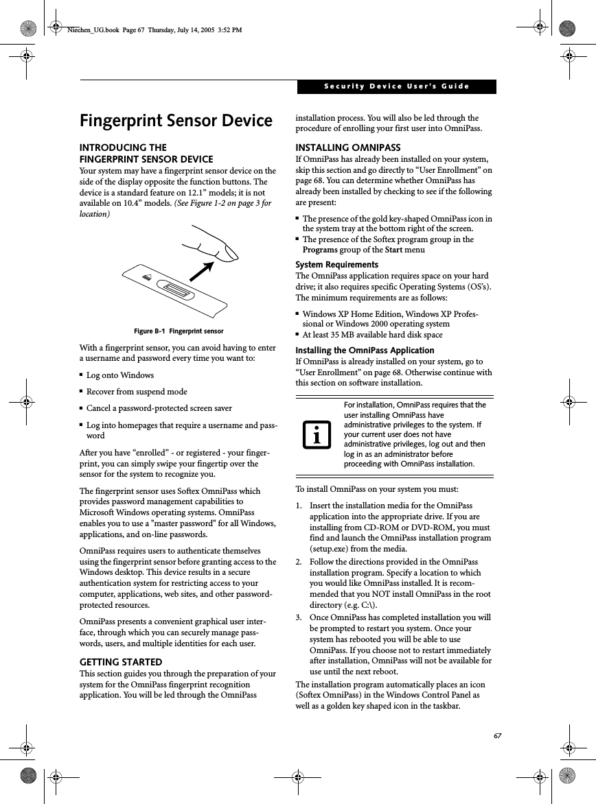
![68Stylistic ST5000 Series Tablet PC User’s Guide – Appendix BVerifying Information about OmniPassAfter you have completed installing OmniPass and restarted your system, you may wish to check the version of OmniPass on your system.To check the version information of OmniPass:1. From the Windows Desktop, double-click the key-shaped OmniPass icon in the taskbar (usually located in the lower right corner of the screen),or,Click the Start button, select Settings, and clickControl Panel (if you are using Windows XP you will see the Control Panel directly in the Start menu; click it, then click Switch to Classic View). Double-click Softex OmniPass in the Control Panel, and the OmniPass Control Center will appear. If it does not appear, then the program is not properly installed,or,Click the Start button, select Programs, and from the submenu select the Softex program group, from that submenu click OmniPass Control Center.2. Select the About tab at the top of the OmniPass Control Panel. The About tab window appears with version information about OmniPass.Uninstalling OmniPassTo remove the OmniPass application from your system:1. Click Start on the Windows taskbar. Select Settings,and then Control Panel.2. Double-click Add/Remove Programs.3. Select OmniPass, and then click Change/Remove.4. Follow the directions to uninstall the OmniPass application.5. Once OmniPass has finished uninstalling, reboot your system when prompted.USER ENROLLMENTBefore you can use any OmniPass features you must first enroll a user into OmniPass.Master Password ConceptComputer resources are often protected with passwords. Whether you are logging into your computer, accessing your email, e-banking, paying bills online, or accessing network resources, you often have to supply credentials to gain access. This can result in dozens of sets of creden-tials that you have to remember.During OmniPass user enrollment a "master password” is created for the enrolled user. This master password “replaces” all other passwords for sites you register with OmniPass. Example: A user, John, installs OmniPass on his system (his home computer) and enrolls an OmniPass user with username “John_01” and password “freq14”. He then goes to his webmail site to log onto his account. He inputs his webmail credentials as usual (username “John_02” and password “tablet”), but instead of clicking [Submit], he directs OmniPass to Remember Password. Now whenever he returns to that site, OmniPass will prompt him to supply access credentials. John enters his OmniPass user credentials (“John_01” and “freq14”) in the OmniPass authentication prompt, and he is allowed into his webmail account. He can do this with as many web sites or password protected resources he likes, and he will gain access to all those sites with his OmniPass user credentials (“John_01” and “freq14”). This is assuming he is accessing those sites with the system onto which he enrolled his OmniPass user. OmniPass does not actually change the credentials of the password protected resource. If John were to go to an Internet cafe to access his webmail, he would need to enter his original webmail credentials (“John_02” and “tablet”) to gain access. If he attempts his OmniPass user credentials on a system other than where he enrolled that OmniPass user, he will not gain access.Basic EnrollmentThe Enrollment Wizard will guide you through the process of enrolling a user. Unless you specified other-wise, after OmniPass installation the Enrollment Wizard will launch on Windows login. If you do not see the Enrollment Wizard, you can bring it up by clicking Starton the Windows taskbar; select Programs; select Softex;click OmniPass Enrollment Wizard.1. Click Enroll to proceed to username and password verification. By default, the OmniPass Enrollment Wizard enters the credentials of the currently logged in Windows user.2. Enter the password you use to log in to Windows. This will become the “master password” for this For uninstallation, OmniPass requires that the user uninstalling OmniPass have administrative privileges to the system. If your current user does not have administrative privileges, log out and then log in as an administrator before proceeding with OmniPass uninstallation.The basic enrollment procedure assumes you have no hardware authentication devices or alternate storage locations that you wish to integrate with OmniPass. If you desire such functionality, consult the appropriate sections after reviewing this section.Niechen_UG.book Page 68 Thursday, July 14, 2005 3:52 PM](https://usermanual.wiki/Fujitsu-Client-Computing/WB0042/User-Guide-724789-Page-79.png)
![69Security Device User’s GuideOmniPass user. In most cases, the Domain: value will be your Windows computer name. In a corporate environment, or when accessing corporate resources, the Domain: may not be your Windows computer name. Click [Next] to continue.3. In this step OmniPass captures your fingerprint. Refer to “Enrolling a Fingerprint” on page 69 for additional information.4. Next, choose how OmniPass notifies you of various events. We recommend you keep Taskbar Tips onBeginner mode taskbar tips and Audio Tips on at least Prompt with system beeps only until you get accustomed to how OmniPass operates. Click [Next]to proceed with user enrollment. You will then see a Congratulations screen indicating your completion of user enrollment.5. Click [Done] to exit the OmniPass Enrollment Wizard. You will be asked if you’d like to log in to OmniPass with your newly enrolled user; click [Yes].Enrolling a FingerprintEnrolling a fingerprint will increase the security of your system and streamline the authentication procedure. You enroll fingerprints in the OmniPass Control Center. With an OmniPass user logged in, double-click the system tray OmniPass icon. Select the User Settings tab and click Enrollment under the User Settings area. Click Enroll Authentication Device and authenticate at the authentication prompt to start device enrollment.1. During initial user enrollment, you will be prompted to select the finger you wish to enroll. Fingers that have already been enrolled will be marked by a green check. The finger you select to enroll at this time will be marked by a red arrow. OmniPass allows you to re-enroll a finger. If you choose a finger that has already been enrolled and continue enrollment, OmniPass will enroll the fingerprint, overwriting the old fingerprint. Select a finger to enroll and click [Next].2. It is now time for OmniPass to capture your selected fingerprint. It may take a several capture attempts before OmniPass acquires your fingerprint. Should OmniPass fail to acquire your fingerprint, or if the capture screen times out, click [Back] to restart the fingerprint enrollment process. Your system has a “swipe” fingerprint sensor. A swipe sensor is small and resembles a skinny elongated rect-angle. To capture a fingerprint, gently swipe or pull your fingertip over the sensor (starting at the second knuckle) in the direction of the arrow. Swiping too fast or too slow will result in a failed capture. The Choose Finger screen has a [Practice] button; click it to practice capturing your fingerprint. When you are comfortable with how your fingerprint is captured, proceed to enroll a finger.3. Once OmniPass has successfully acquired the finger-print, the Verify Fingerprint screen will automati-cally appear. To verify your enrolled fingerprint, place your fingertip on the sensor and hold it there as if you were having a fingerprint captured. Successful fingerprint verification will show a green fingerprint in the capture window and the text Ve r i f i c a t i o n Successful under the capture window.USING OMNIPASSYou are now ready to begin using OmniPass. Used regu-larly, OmniPass will streamline your authentication procedures.Password ReplacementYou will often use the password replacement function. When you go to a restricted access website (e.g., your bank, your web-based email, online auction or payment sites), you are always prompted to enter your login credentials. OmniPass can detect these prompts and you can teach OmniPass your login credentials. The next time you go to that website, you can authenticate with your fingerprint to gain access.OmniPass Authentication ToolbarAfter installing OmniPass and restarting, you will notice a dialog you have not seen before at Windows Logon. This is the OmniPass Authentication Toolbar, and it is displayed whenever the OmniPass authentication system is invoked. The OmniPass authentication system may be invoked frequently: during Windows Logon, during OmniPass Logon, when unlocking your workstation, when resuming from standby or hibernate, when unlocking a password-enabled screensaver, during pass-word replacement for remembered site or application logins, and more. When you see this toolbar, OmniPass is prompting you to authenticate.The Logon Authentication window indicates what OmniPass-restricted function you are attempting. The icons in the lower left (fingerprint and key) show what authentication methods are available to you. Selected authentication methods are highlighted while unselected methods are not. When you click the icon for an unse-lected authentication method, the authentication prompt associated with that method is displayed.When prompted to authenticate, you must supply the appropriate credentials: an enrolled finger for the finger-print capture window or your master password for the master password prompt (the key icon).Remembering a PasswordOmniPass can remember any application, GUI, or pass-word protected resource that has a password prompt.Niechen_UG.book Page 69 Thursday, July 14, 2005 3:52 PM](https://usermanual.wiki/Fujitsu-Client-Computing/WB0042/User-Guide-724789-Page-80.png)
![70Stylistic ST5000 Series Tablet PC User’s Guide – Appendix BUsing the following procedure, you can store a set of credentials into OmniPass. These credentials will then be linked to your “master password” or fingerprint.Go to a site that requires a login (username and pass-word), but do not log in yet. At the site login prompt, enter your username and password in the prompted fields, but do not enter the site (do not hit [Enter], [Submit], [OK], or Login). Right-click the OmniPass system tray icon and select Remember Password from the submenu. The Windows arrow cursor will change to a golden key OmniPass cursor. Click this OmniPass cursor in the login prompt area, but do not click the [Login] or [Submit] button.Associating a Friendly NameAfter clicking the OmniPass key cursor near the login prompt, OmniPass will prompt you to enter a “friendly name” for this site. You should enter something that reminds you of the website, the company, or the service you are logging into. In its secure database, OmniPass associates this friendly name with this website.Additional Settings for Remembering a SiteWhen OmniPass prompts you to enter a “friendly name” you also have the opportunity to set how OmniPass authenticates you to this site. There are three effective settings for how OmniPass handles a remembered site.The default setting is Automatically click the “OK” or “Submit” button for this password protected site once the user is authenticated. With this setting, each time you navigate to this site OmniPass will prompt you for your master password or fingerprint authentication device. Once you have authenticated with OmniPass, you will automatically be logged into the site.Less secure is the option to Automatically enter this password protected site when it is activated. Do not prompt for authentication. Check the upper box to get this setting, and each time you navigate to this site OmniPass will log you into the site without prompting you to authenticate.If you uncheck both boxes in Settings for this Password Site, OmniPass will prompt you for your master pass-word or fingerprint authentication device. Once you have authenticated with OmniPass your credentials will be filled in to the site login prompt, but you will have to click the website [OK], [Submit], or [Login] button to gain access to the site.Click Finish to complete the remember password proce-dure. The site location, the credentials to access the site, and the OmniPass authentication settings for the site are now stored in the OmniPass secure database. The OmniPass authentication settings (Settings for this Pass-word Site) can always be changed in Vault Management.Logging in to a Remembered SiteWhether or not OmniPass prompts you to authenticate when you return to a remembered site is determined by Settings for this Password Site and can be changed in Vault Management.The following cases are applicable to using OmniPass to login to: Windows, remembered web sites, and all other password protected resources.With Master PasswordOnce you return to a site you have remembered with OmniPass, you may be presented with a master pass-word prompt. Enter your master password and you will be allowed into the site.Logging into Windows with a Fingerprint DeviceWhen logging into Windows with a fingerprint device, the fingerprint capture window will now appear next to the Windows Login screen. Place your enrolled fingertip on the sensor to authenticate. You will be simultaneously logged into Windows and OmniPass. The capture window will also appear if you have used Ctrl-Alt-Del to lock a system, and the fingerprint device can be used to log back in as stated above.In Windows XP, your login options must be set either for classic login, or for fast user switching and logon screen to be enabled to use your fingerprint to log on to Windows. To change this go to Control Panel, select User Accounts and then click Change the way users log on or off. If your Windows screensaver is password protected, the fingerprint capture window will now appear next to screensaver password dialog during resume. You can authenticate to your screensaver pass-word prompt with your enrolled finger.Password ManagementOmniPass provides an interface that lets you manage your passwords. To access this GUI, double-click the This setting is more convenient in that whenever you go to a site remembered with this setting, you will bypass any authentication procedure and gain instant access to the site. But should you leave your system unattended with your OmniPass user logged in, anyone using your system can browse to your password protected sites and gain automatic access.If a machine is locked and OmniPass detects a different user logging back in with a fingerprint, the first user will be logged out and the second user logged in.Niechen_UG.book Page 70 Thursday, July 14, 2005 3:52 PM](https://usermanual.wiki/Fujitsu-Client-Computing/WB0042/User-Guide-724789-Page-81.png)
![71Security Device User’s GuideOmniPass key in the system tray. Click Vault Manage-ment; you will be prompted to authenticate. Once you gain access to Vault Management, click Manage Pass-words under Vault Settings. You will see the Manage Passwords interface, with a list of friendly names.You can view the credentials stored for any remembered website by highlighting the desired resource under Pass-word Protected Dialog and clicking Unmask Values.Should a password be reset, or an account expire, you can remove stored credentials from OmniPass. Highlight the desired resource under Password Protected Dialog and click Delete Page. You will be prompted to confirm the password deletion.The two check boxes in Manage Passwords govern whether OmniPass prompts you to authenticate or directly logs you into the remembered site.OmniPass will overwrite an old set of credentials for a website if you attempt to use Remember Password on an already remembered site. The exception to the above rule is the resetting of your Windows password. If your password is reset in Windows, then the next time you login to Windows, OmniPass will detect the password change and prompt you to “Update” or “Reconfirm” your password with OmniPass. Enter your new Windows password in the prompt(s) and click OK and your OmniPass "master password" will still be your Windows password.OmniPass User IdentitiesIdentities allow OmniPass users to have multiple accounts to the same site (e.g., bob@biblomail.com and boballen@biblomail.com). If OmniPass did not provide you identities, you would be limited to remembering one account per site.To create and manage identities, double-click the OmniPass key in the system tray. Click Vault Manage-ment; OmniPass will prompt you to authenticate. Once you gain access to Vault Management, click Manage Identities under Vault Settings. You can only manage the identities of the currently logged in OmniPass userTo add a new identity, click New Identity or double-clickClick here to add a new identity. Name the new identity and click [OK], then click [Apply]. You can now switch to the new identity and start remembering passwords.To delete an identity, highlight the identity you want to delete and click [Delete Identity], then click [Apply].To set the default identity, highlight the identity you want as default and click [Set as Default]; click [Apply] to ensure the settings are saved. If you log in to OmniPass with a fingerprint device, you will automati-cally be logged in to the default identity for that OmniPass user. You can choose the identity with which you are logging in if you login using "master password".Choosing User Identity during LoginTo choose your identity during login, type your user-name in the User Name: field. Press [Tab] and see that the Domain: field self-populates. Click the Password: field to bring the cursor to it, and you will see the pull-down menu in the Identity: field. Select the identity you wish to login as and then click OK to login.Switch User IdentityTo switch identities at any time, right-click the OmniPass system tray icon and click Switch User Iden-tity from the submenu. The Switch Identity dialog will appear. Select the desired identity and then click OK.Identities and Password ManagementOn the Manage Passwords interface of the Va u l t Management tab of the OmniPass Control Center, there is a pull-down selection box labeled, Identity. This field lets you choose which identity you are managing pass-words for. When you select an identity here, only those password protected dialogs that are associated with that identity are shown. You can perform all the functions explained in “Password Management” on page 70.CONFIGURING OMNIPASSThis section gives an overview of both the Export/Import function and the OmniPass Control Center. Exporting and Importing UsersUsing the OmniPass Control Center, you can export and import users in and out of OmniPass. The export process backs up all remembered sites, credentials, and any enrolled fingerprints for an OmniPass user. All OmniPass data for a user is backed up to a single encrypted database file. During the import process, the Windows login of the exported user is required. If the When you delete an identity, all of its associated remembered sites and password protected dialogs are lost.Niechen_UG.book Page 71 Thursday, July 14, 2005 3:52 PM](https://usermanual.wiki/Fujitsu-Client-Computing/WB0042/User-Guide-724789-Page-82.png)
![75Security Device User’s GuideTrusted Platform Module InstallationThis disc contains several utilities that allow you to enhance the security of your system using the optional Trusted Platform Module (TPM) contained in the sys-tem. TPM is a Trusted Computer Group (TCG)-compli-ant embedded security chip that allows computers to run applications more securely and to make transactions and communications more trustworthy. TPM is an important component of the Fujitsu Security Platform.ProcedureBe sure you have a built-in or external drive attached to your system that can read CDs. You will also need a means to write to removable media during the installa-tion.Enabling the Security Chip in BIOS1. Before installing the TPM software, you will need to enable the security chip in the system BIOS. To do so:• If your system is running, click [Start] -> Shut Down, and select Restart. Click [OK].• If the system is not running, power it up.2. When the Fujitsu logo appears, press the [F2] but-ton. The BIOS Setup Utility will appear.3. Open the Security menu, scroll down to Set Super-visor Password, and enter a password (if not already set).4. While in the Security menu, scroll down to Security Chip Setting, and click on it. The Security Chip Set-ting submenu will appear.5. Click on Security Chip to enable it.6. Click [F10] to save changes and exit.Installing the TPM Applications1. Insert the “Trusted Platform Module Drivers and Applications CD” in the drive.2. The setup program should start the installation automatically. If the installation does not start auto-matically, go to the setup.exe file on the disc and double-click on it.3. Follow the instructions that appear on your screen to load the drivers and applications for TPM.4. After loading the software, you will be prompted to reboot your system. Remove the CD from the drive, then reboot.5. After rebooting, the Security Platform Installation Wizard will open and lead you through the setup and customization of the TPM applications. Getting Help■For detailed help about installing the TPM applica-tions, go to the readme.txt file on the disc.■For in-depth help and information about the TPM applications, double-click on the Security Platform icon in the system tray, and click {Getting Started Guide].• The use of this disc requires that you have a device capable of reading CDs attached to your system. If you do not have a built-in CD or DVD player, you will need to attach an external player. • The use of this disc also requires a device capable of writing to removable media (such as a floppy disk drive, CD-RW drive, or PCMCIA memory card). This drive will be used to store the Emergency Recovery Token file and -- if desired -- the Emergency Recovery Archive file. For more information on available external devices, visit our Web site at: us.fujitsu.com/computers.When installing the software, be sure to create Emergency Recovery Archive and Emergency Recovery Token files when prompted by the Security Platform Initialization Wizard. These files will be necessary in the event of hardware failure. Failure to create these files could result in a loss of the Security Platform owner key,which is the physical root for secrets as well as the logical root for all Security Platform user-specific keys. The Initialization Wizard provides step-by-step instructions for creating the files. Niechen_UG.book Page 75 Thursday, July 14, 2005 3:52 PM](https://usermanual.wiki/Fujitsu-Client-Computing/WB0042/User-Guide-724789-Page-86.png)