Fujitsu Client Computing WB0045 LIFEBOOK P SERIES WITH AR5BXB6 11ABG WLAN & BT User Manual USERS MANUAL 2
Fujitsu Limited LIFEBOOK P SERIES WITH AR5BXB6 11ABG WLAN & BT USERS MANUAL 2
Contents
- 1. USERS MANUAL
- 2. USERS MANUAL 1
- 3. USERS MANUAL 2
USERS MANUAL 2
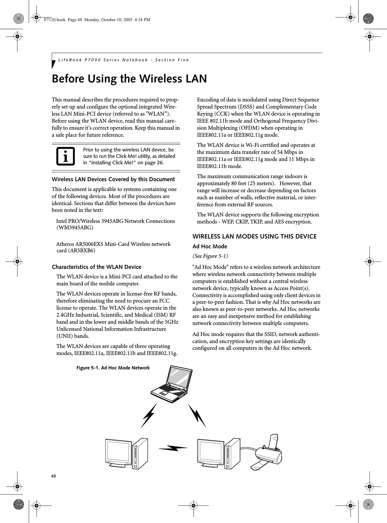
![50LifeBook P7000 Series Notebook - Section FiveDeactivation using the Wireless On/Off SwitchThe WLAN device can be deactivated quickly and effi-ciently by toggling the Wireless On/Off Switch to the Off position. (Figure 5-3)The Wireless On/Off switch has no effect on non-Wire-less LAN models.Figure 5-3. Wireless LAN On/Off Switch LocationDeactivation using the Intel PROSet SoftwareThe WLAN device can also be deactivated in Windows using the Intel PROSet Software. The procedure to accomplish this:1. Click [Start]-> [All Programs].2. Select Intel ProSet Wireless, then click on Intel ProSet Wireless from the menu that appears. The Intel ProSet Wireless utility will be displayed.3. At the bottom left corner of the window, select Wireless Off from the dropdown list.Deactivation using Atheros Client Utility software1. Right-click on Atheros Client Utility icon in the system tray. Select “Open Atheros Client Utility” from the menu.2. Choose Action and click Disable Radio.ACTIVATING THE WLAN DEVICEActivation of the WLAN device can be accomplished using the same methods as the deactivation process■Using the Wireless On/Off Switch■In Windows using the Intel PROSet Software or Atheros SoftwareWireless LANOn/Off SwitchP7120.book Page 50 Monday, October 10, 2005 4:38 PM](https://usermanual.wiki/Fujitsu-Client-Computing/WB0045.USERS-MANUAL-2/User-Guide-725912-Page-4.png)
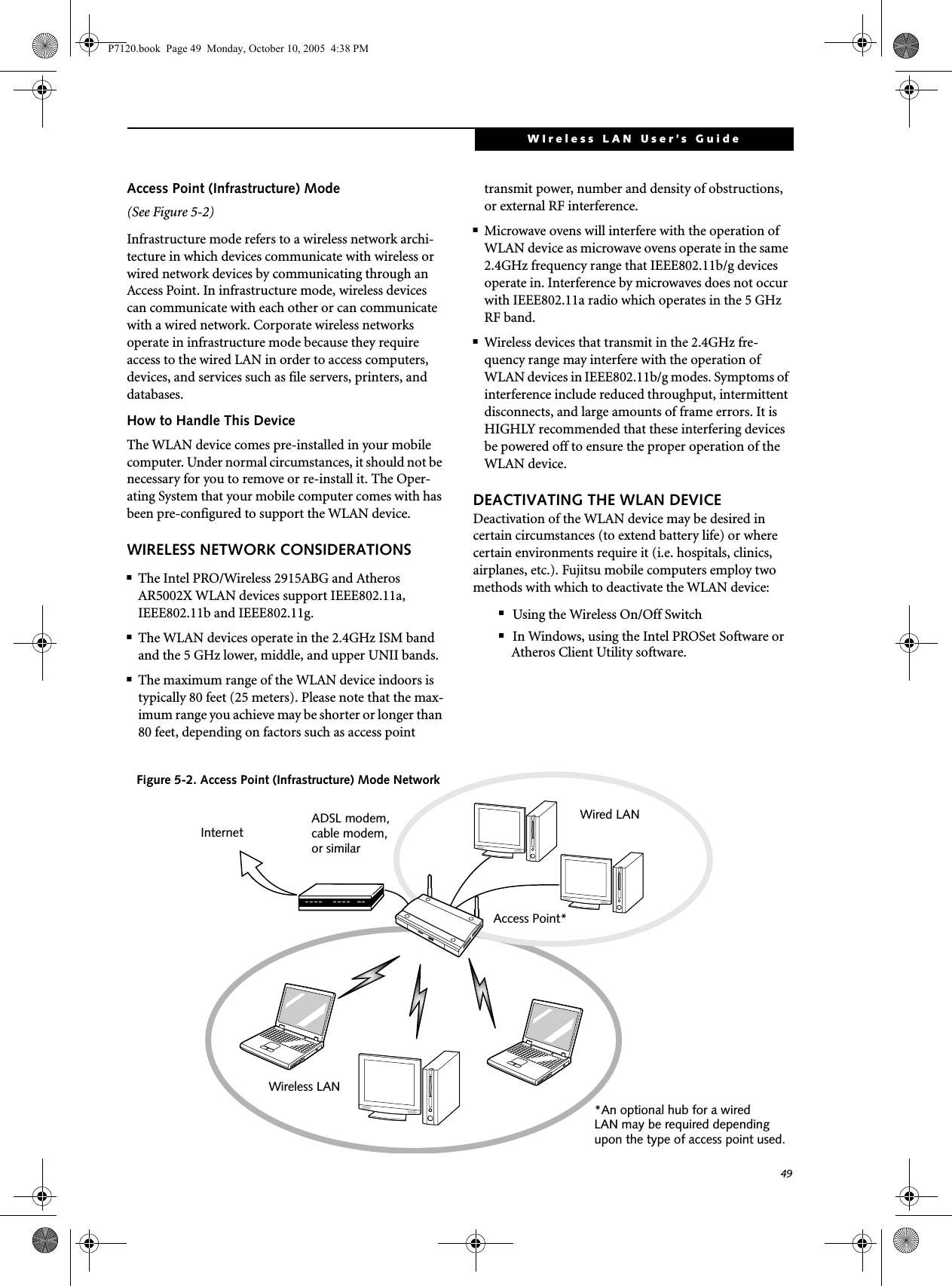
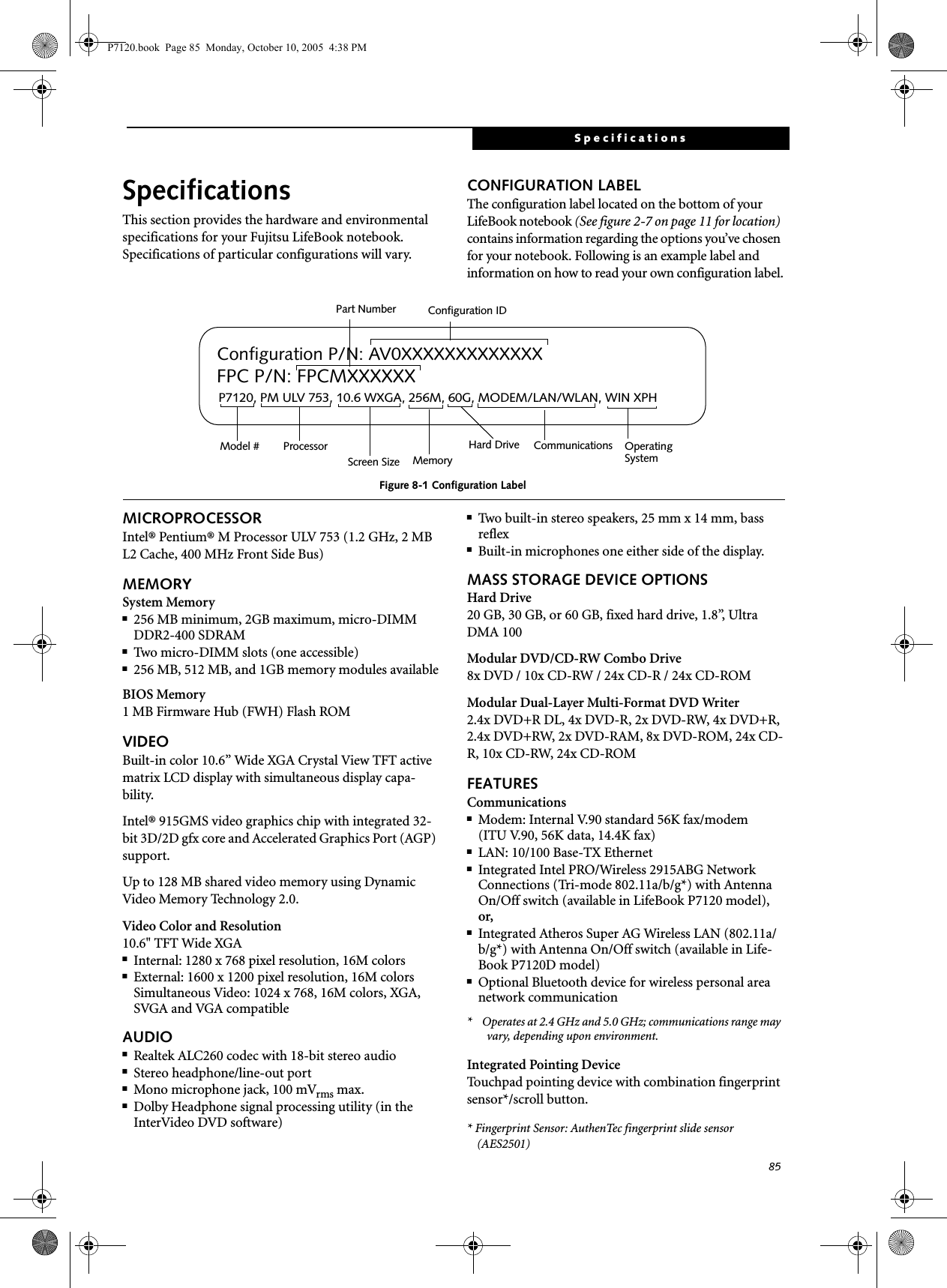
![51WIreless LAN User’s Guide Configuration of the WLAN DeviceThe WLAN Device can be configured to establish wire-less network connectivity using one of the following tools:■Intel PROSet Software - The Intel PROSet Software allows for multiple profile setup and supports auto-matic profile switching. Support for most industry standard security solutions is contained in this soft-ware.■Atheros Client Utility - The Atheros Client Utility soft-ware allows for multiple profile setups and supports automatic profile switching. Support for most indus-try standard security solutions is contained in this software.FLOW OF OPERATIONS1. Activate the WLAN Device (See Activating the WLAN Device on page 50 for more information).2. Configure the Wireless Network parameters (See Configure Wireless Network Parameters on page 51 for more information).■Enter the network name (SSID)■Choose the appropriate WLAN architecture (Ad Hoc or Infrastructure)■Choose Authentication method: Open, Shared, WPA-Enterprise, WPA2-Enterprise, WPA-Personal, or WPA2-Personal■If using static WEP keys, enter static WEP key and choose key index. 3. Configure network settings (See Configure Net-work Parameters on page 51 for more information)■TCP/IP settings■Workgroup or Domain settings.CONFIGURATION USING INTEL PROSET SOFTWAREThis section explains the procedure to properly configure the WLAN device using the Intel PROSet Soft-ware. Pre-defined parameters will be required for this procedure. Please consult with your network adminis-trator for these parameters:Network Name - Also known as the SSIDNetwork Key (WEP) - Required if using static WEP keys. Authentication Type - Open, Shared, WPA, or WPA-PSKProcedure1. Activate the WLAN device using either the Wireless On/Off Switch or the Intel PROSet software.2. Click the [Start] button first and then [All Pro-grams].3. Click the icon [Intel PROSet Wireless] to execute the Intel PROSet Wireless software.4. Click the [Add] button. The General Settings dialog displays. 5. Enter a profile name in the Profile Name field. 6. Enter the network SSID, in the Network Name (SSID) field. 7. Click Infrastructure or Ad Hoc for the operating mode. 8. Click [Advanced].9. The Mandatory Access Point option is only used if Infrastructure mode is selected. Use this option to connect to a specific access point. Enter the MAC address for the access point. Click OK to save the setting and return to the General Settings page. 10. Click [Next].11. If you are using Cisco CCX, click Cisco Options to enable Cisco CKIP data encryption on the Security Settings page. Check the Cisco Compatible Exten-sions Options. If you have checked the Cisco's "Mixed-Cell" box in the Advanced Setting, this option must also be checked.12. Click [OK].13. Click Next.14. Select Open, Shared, WPA-Enterprise, WPA2-Enterprise, WPA-Personal, or WPA2-Personal in the Network Authentication options. 15. Select either None, WEP, CKIP (if Enable Cisco Cli-ent eXtentions is enabled, use CKIP or WEP), or TKIP for the data encryption. 16. If WEP is selected, select either 64 or 128-bit for the Encryption Level. 17. Select the key index 1, 2, 3 or 4. 18. Enter the WEP key if required. If your network does not employ a 802.1x/EAP security mechanism, please skip to step 24.P7120.book Page 51 Monday, October 10, 2005 4:38 PM](https://usermanual.wiki/Fujitsu-Client-Computing/WB0045.USERS-MANUAL-2/User-Guide-725912-Page-5.png)
![52LifeBook P7000 Series Notebook - Section Five19. Click the Enable 802.1x checkbox to enable the 802.1x security option. Please contact your network administrator if configuration of this setting is required.20. Select the appropriate Authentication Type. Please contact your network administrator if configura-tion of this setting is required.21. After selecting your authentication type, enter the user name, domain, and password of the user you have created on the authentication server. The user name and password do not have to be the same as name and password of your current Windows user login.22. Click [OK] to save the settings.23. From the Intel ProSet Wireless page, click the new profile name shown in the Profile List. Use the up and down arrows to position the priority of the new profile in the priority list. 24. Click the Connect button to connect to the net-work. 25. Click [Close] if you want to close the Intel(R) PROSet for Wireless window.CONFIGURATION USING ATHEROS CLIENT UTILITY SOFTWAREThis section explains the procedure to properly configure the WLAN device using the Atheros Client Utility. Pre-defined parameters will be required for this procedure. Please consult with your network adminis-trator for these parameters:Network Name - Also known as the SSIDNetwork Key (WEP) - Required if using static WEP keys. Authentication Type - Open, Shared, WPA, or WPA-PSKProcedure1. Activate the WLAN device using either the Wireless On/Off Switch or the Atheros Client Utility2. Right-click on the “Atheros Client Utility” icon in the system tray, and select “Open Atheros Client Utility” from the menu.3. From the Current Status page, click the Profile Management tab. 4. If this is your first time using this utility, highlight the profile [Default] and Click the [Modify] button, otherwise Click the [New] button. The General Set-tings dialog displays. 5. From the General page, enter a profile name in the Profile Name field. 6. Enter the network SSID, in the SSID1 field. If you wish to create a profile that can connect to up to 3 different wireless networks, SSID's can be entered in the SSID2 and SSID3 fields as well.7. Click the Security tab. 8. The Security tab allows for the configuration of the Security modes listed in the table below. Please select the radio button of the desired security mode. If these settings are not known to you, please consult with your network administrator for the correct settings. 9. Click OK10. Click the Advanced tab11. The Advanced tab allows for the configuration of the options detailed in the table below.Field Name DescriptionWPA Enables the use of Wi-Fi Protected Access. Choosing WPA opens the WPA EAP drop-down menu. Options include TLS and PEAP. If these settings are not known to you, please consult with your network administrator for the correct settings. WPA-PSK Enables WPA-Pre-Shared Key. Click on the Configure button to enter the WPA Passphrase. If these settings are not known to you, please consult with your network administrator for the correct settings. 802.1x Enables 802.1x security. If these settings are not known to you, please consult with your network administrator for the correct settings. Choosing this option opens the 802.1x EAP type drop-down menu. Options include TLS, PEAP, and LEAPPre-Shared Key Enables the use of pre-shared keys that are defined on both the access point and the station. This is where static WEP keys are entered. Click the Configure button to fill in the Define Pre-Shared Keys window.None No securityP7120.book Page 52 Monday, October 10, 2005 4:38 PM](https://usermanual.wiki/Fujitsu-Client-Computing/WB0045.USERS-MANUAL-2/User-Guide-725912-Page-6.png)
![53WIreless LAN User’s Guide .12. Click OK13. If the profile you just created does not activate immediately, click the Profile Management tab, highlight the desired Profile, and click Activate.14. Click [Close] if you want to close the Atheros Client Utility.CONNECTION TO THE NETWORKThis section explains connection to the network.If there is an administrator of the network, contact the network administrator for data settings.Setting the networkPerform the “Setting TCP/IP” and “Confirming the computer and work group names” operations required for network connection.Setting TCP/IP1. Click the [Start] button first and then [Control Panel].2. If the Control Panel is in Category view, switch to Classic view by clicking “Switch to Classic View” under Control Panel the left frame. (If you are already in Classic view, “Switch to Category View” will be displayed.) 3. Double-click [Network Connections]. A list of cur-rently installed networks will be displayed.4. Right-click [Wireless Network Connection] in the list, and then click [Properties] in the menu dis-played. The [Wireless Network Connection Proper-ties] window will be displayed.5. Click the [General] tab if it is not already selected.6. Click [Internet Protocol (TCP/IP] and then click [Properties]. The [Internet Protocol (TCP/IP) Properties] window will be displayed.7. Set the IP address as follows:■For ad hoc connection: Select [Use the following IP address:] and then enter data for [IP address] and [Subnet mask]. See page 60 for IP address setting.■For access point (infrastructure) connection: If your network uses DHCP, select [Obtain an IP address automatically] and [Obtain DNS server address automatically]. If your network uses static IP addresses, consult with your network adminis-trator for the correct IP address settings.8. Click the [OK] button. Processing will return to the [Wireless Network Connection Properties] window.9. Click the [OK] button.10. Close the [Network Connection] window. Following this operation, confirm the names of the computer and the workgroup as follows.Confirming the computer and work group names1. Click the [Start] button, then [Control Panel].2. If the Control Panel is in Category view, switch to Classic view by clicking “Switch to Classic View” under Control Panel the left frame. (If you are already in Classic view, “Switch to Category View” will be displayed.) 3. Double-click the [System] icon. The [System Prop-erties] window will be displayed.4. Click the [Computer Name] tab.Field Name DescriptionPower Save ModeOptions are Maximum, Normal, or OffNetwork Type Options are AP (Infrastructure) or Ad Hoc802.11b PreambleSpecifies the preamble setting in 802.11b. The default setting is Short and Long (Access Point mode), which allows both short and long headers in the 802.11b frames. Set to Long Only to override allowing short frames.Transmit Power LevelOptions are 100 mW, 63 mW, 50 mW, and 40 mW.Wireless Mode Specifies 5 GHz 54 Mbps, 5 GHz 108 Mbps, 2.4 GHz 11 Mbps, or 2.4 GHz 54 Mbps operation in an access point network.Wireless Mode when Starting Ad Hoc NetworkSpecifies 5GHz 54 Mbps, 5 GHz 108 Mbps, 2.4 GHz 11 Mbps, or 2.4 GHz 54 Mbps to start an Ad Hoc network if no matching network name is found after scanning all available modes.To change the setting of the IP address, you need to be logged in from Windows as an administrator.To modify the computer name and/or the work group name, you need to be logged in from Windows as an administrator.P7120.book Page 53 Monday, October 10, 2005 4:38 PM](https://usermanual.wiki/Fujitsu-Client-Computing/WB0045.USERS-MANUAL-2/User-Guide-725912-Page-7.png)
![54LifeBook P7000 Series Notebook - Section Five5. Confirm the settings of [Full computer name:] and [Workgroup:].a. The setting of [Full computer name:] denotes the name for identifying the computer. Any name can be assigned for each personal computer. Enter the desired name in less than 15 ASCII character code format. Identifiability can be enhanced by entering the model number, the user name, and other factors.b. [Workgroup name] is the group name of the network. Enter the desired name in less than 15 ASCII character code format.For ad hoc connection: Assign the same network name to all personal computers existing on the network.For access point (infrastructure) connection: Assign the name of the work group to be accessed.6. Click the [OK] button. If a message is displayed that requests you to restart the personal computer, click [Yes] to restart the computer.Setting the sharing functionSet the sharing function to make file and/or printer sharing with other network-connected personal computers valid.This operation is not required unless the sharing func-tion is to be used.The folder and printer for which the sharing function has been set will be usable from any personal computer present on the network.Setting the Microsoft network-sharing service1. Click the [Start] button first and then [Control Panel]. 2. If the Control Panel is in Category view, switch to Classic view by clicking “Switch to Classic View” under Control Panel the left frame. (If you are already in Classic view, “Switch to Category View” will be displayed.) 3. Double-click [Network Connections]. A list of cur-rently installed networks will be displayed.4. Right-click [Wireless Network Connection] in the list, and then click [Properties] in the menu dis-played. The [Wireless Network Connection Proper-ties] window will be displayed.5. If [File and Printer Sharing for Microsoft Net-works] is displayed, proceed to step 6. If [File and Printer Sharing for Microsoft Networks] is not dis-played, skip to step 7.6. Make sure that the [File and Printer Sharing for Microsoft Networks] check box is checked, and then click the [OK] button. Skip to “Setting file-sharing function”.7. Click [Install]. The [Select Network Component Type] window will be displayed.8. Click [Service], then click the [Add] button. The [Select Network Service] window will be displayed.9. Click [File and Printer Sharing for Microsoft Net-works] and then click the [OK] button. Processing will return to the [Wireless Network Connection Properties] window, and [File and Printer Sharing for Microsoft Networks] will be added to the list.10. Click the [Close] button.Setting the file-sharing functionThe procedure for setting the file-sharing function follows, with the “work” folder in drive C: as an example.1. Click the [Start] button first and then [My Com-puter]. 2. Double-click [Local disk (C:)].3. Right-click the “work” folder (or whichever folder you want to share), and then click [Sharing and Security...] in the menu displayed. The [Folder Name Properties] window will be displayed.4. Click [Sharing] if it isn’t already selected.To change the name, click [Change] and then proceed in accordance with the instruction messages displayed on the screen.To share a file and/or the connected printer, you need to be logged in as an administrator. Setting the file-sharing function for the file which has been used to execute Network Setup Wizard is suggested on the screen. For the wireless LAN, however, since security is guaranteed by entry of the network name (SSID) and the network key, the steps to be taken to set the file-sharing function easily without using Network Setup Wizard are given below.P7120.book Page 54 Monday, October 10, 2005 4:38 PM](https://usermanual.wiki/Fujitsu-Client-Computing/WB0045.USERS-MANUAL-2/User-Guide-725912-Page-8.png)
![55WIreless LAN User’s Guide 5. Click the link stating “If you understand the secu-rity risks, but want to share files without running the wizard, click here”.6. Click “Just enable file sharing” and click [OK].7. Check the [Share this folder on the network] check box.8. Click the [OK] button. The folder will be set as a sharable folder, and the display of the icon for the “work.” folder will change.Setting the printer-sharing function1. Click the [Start] button first and then [Printers and FAX]. A list of connected printers will be displayed.2. Right-click the printer for which the sharing func-tion is to be set, and then click [Sharing] in the menu displayed. The property window correspond-ing to the selected printer will be displayed.3. Click the [Sharing] tab.4. Click [Share this printer].5. Enter the sharing printer name in [Share name].6. Click the [OK] button. Confirming connectionAfter you have finished the network setup operations, access the folder whose sharing has been set for other personal computers. Also, confirm the status of the radio waves in case of trouble such as a network connection failure.Connecting your personal computer to another personal computer1. Click [Start] first and then [My Computer]. The [My Computer] window will be displayed in the left frame.2. Click [My Network Places] in the “Other Places” list. The window [My Network Places] will be dis-played.3. Click [View workgroup computers] under Network Tasks in the left frame.4. Double-click the personal computer to which your personal computer is to be connected. The folder that was specified in “Setting the file-sharing func-tion” on page 54 will be displayed.5. Double-click the folder to be accessed.Confirming the status of the radio1. Right-click the Intel PRO Wireless icon in the lower right corner of the screen.2. Click [Open Intel PROSet for Wireless]. The Intel PROSet for Wireless window opens.3. Contained within the General tab and the Details section (accessed by pressing the [Details] button), you will find the current operating status of the radio. (When the radio is turned off or the com-puter is not yet connected, some of the conditions will not be displayed.)■Profile NameThe current configuration profile is displayed.■Network Name (SSID)Displays the Network Name (SSID) currently used by the radio.■IP AddressThe IP address of the current profile.■Signal QualityDisplays a message stating the current quality of the signal.■Signal StrengthDisplays a graphic representation of the current signal strength.Additionally, in the lower section of the display, you will see a variety of different measurements related to the WLAN. For additional information about the items, click on the “Help?” button:■Adapter MAC Address■Band■Supported Data RatesTo specify the corresponding folder as a read-only folder, select the [Read only] checkbox under the General tab.Setting the printer-sharing function when Network Setup Wizard has been executed is suggested on the screen. For the wireless LAN, however, since security is guaranteed by entry of the network name (SSID) and the network key, the steps to be taken to set the printer-sharing function without using Network Setup Wizard are laid down below.In the case of access point (infrastructure) connection, enter the necessary data for the access point before confirming connection. Refer to the manual of the access point for the access point setup procedure.P7120.book Page 55 Monday, October 10, 2005 4:38 PM](https://usermanual.wiki/Fujitsu-Client-Computing/WB0045.USERS-MANUAL-2/User-Guide-725912-Page-9.png)

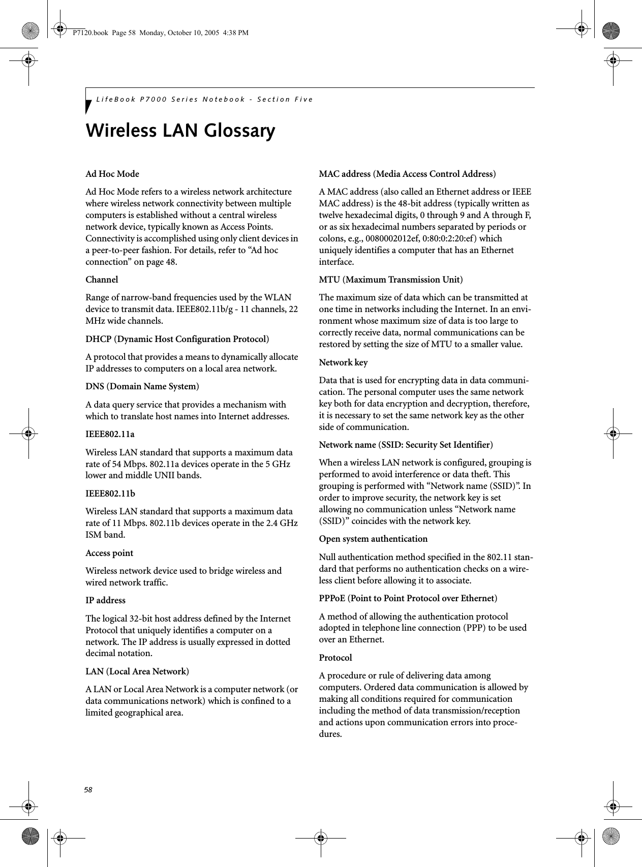
![60LifeBook P7000 Series Notebook - Section FiveIP address informationIf IP address is unknown, set IP address as follows:If you have an access point (DHCP server) on the network, set the IP address as follows:[Obtain an IP address automatically]If the IP address is already assigned to the computer in the network, ask the network administrator to check the IP address to be set for the computer.If no access point is found in the network:An IP address is expressed with four values in the range between 1 and 255.Set the each computer as follows: The value in paren-theses is a subnet mask.<Example>Computer A: 192.168.100.2 (255.255.255.0)Computer B: 192.168.100.3 (255.255.255.0)Computer C: 192.168.100.4 (255.255.255.0)::Computer X: 192.168.100.254 (255.255.255.0)IP addressing is much more complicated than can be briefly explained in this document. You are advised to consult with your network administrator for additional information.A DHCP server is a server that automatically assigns IP addresses to computers or other devices in the network. There is no DHCP server for the AdHoc network.P7120.book Page 60 Monday, October 10, 2005 4:38 PM](https://usermanual.wiki/Fujitsu-Client-Computing/WB0045.USERS-MANUAL-2/User-Guide-725912-Page-14.png)
![62LifeBook P7000 Series Notebook - Section FiveUsing the Bluetooth DeviceThe Integrated Bluetooth module (EYTF3CSFT) is an optional device available for Fujitsu mobile computers. WHAT IS BLUETOOTHBluetooth technology is designed as a short-range wire-less link between mobile devices, such as laptop computers, phones, printers, and cameras. Bluetooth technology is used to create Personal Area Networks (PANs) between devices in short-range of each other. WHERE TO FIND INFORMATIONABOUT BLUETOOTHThe Bluetooth module contains a robust Help user’s guide to assist you in learning about operation of the Bluetooth device.To access the Help file, click [Start] -> All Programs, and click on Toshiba. Select Bluetooth, then select User’s Guide.For additional information about Bluetooth Technology, visit the Bluetooth Web site at: www.bluetooth.com.FCC Radiation Exposure StatementThis equipment complies with FCC radiation exposure limits set forth for an uncontrolled environment.The transmitters in this device must not be co-located or operated in conjunction with any other antenna or transmitter.Canadian NoticeTo prevent radio interference to the licensed service, this device is intended to be operated indoors and away from windows to provide maximum shielding. Equipment (or its transmit antenna) that is installed outdoors is subject to licensing.WarrantyUsers are not authorized to modify this product. Any modifications invalidate the warranty.This equipment may not be modified, altered, or changed in any way without signed written permission from Fujitsu. Unauthorized modification will void the equipment authorization from the FCC and Industry Canada and the warranty.The Wireless LAN/Bluetooth On/Off Switch will power off both the optional wireless LAN and Bluetooth devices at the same time. To enable or disable either one of the devices individually, perform the following steps:1. Slide the Wireless LAN/Bluetooth on/off switch to On position.2. In the Control Panel, double-click the Fujitsu Radio Control icon.3. In the window that appears, click the button associated with Bluetooth and/or Wireless LAN Status to enable or dis-able the individual devices.4. Click [OK].P7120.book Page 62 Monday, October 10, 2005 4:38 PM](https://usermanual.wiki/Fujitsu-Client-Computing/WB0045.USERS-MANUAL-2/User-Guide-725912-Page-16.png)


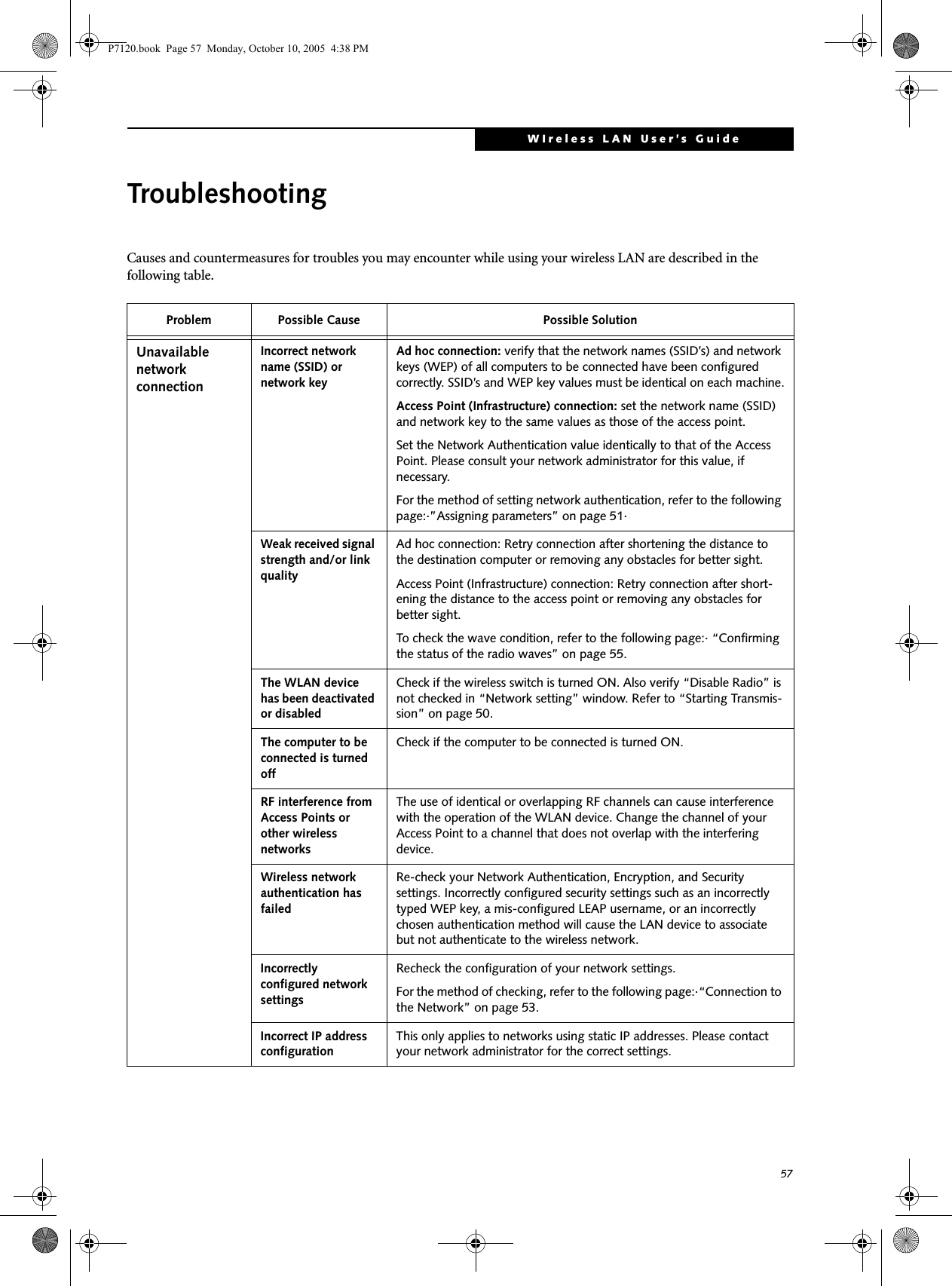
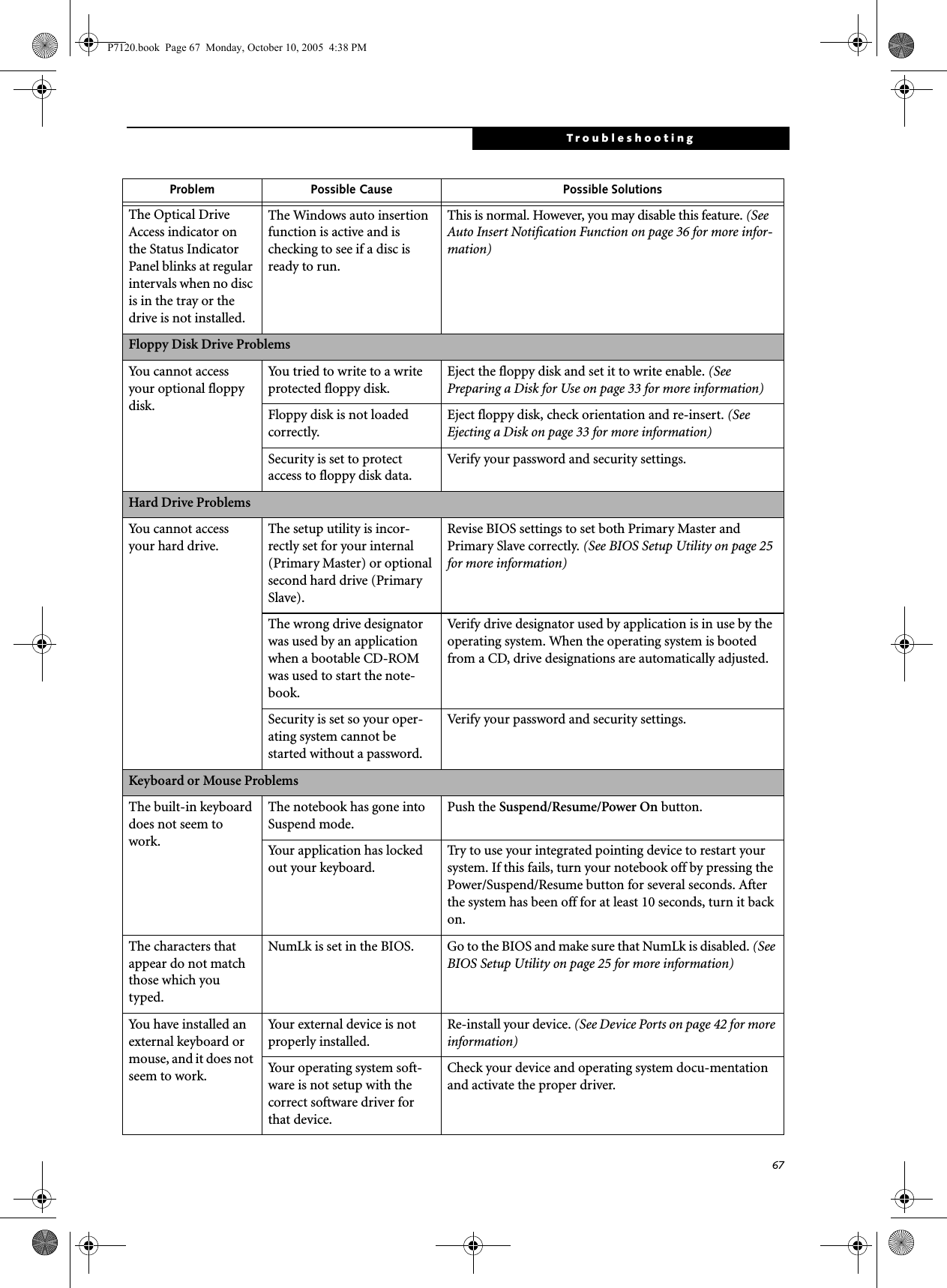
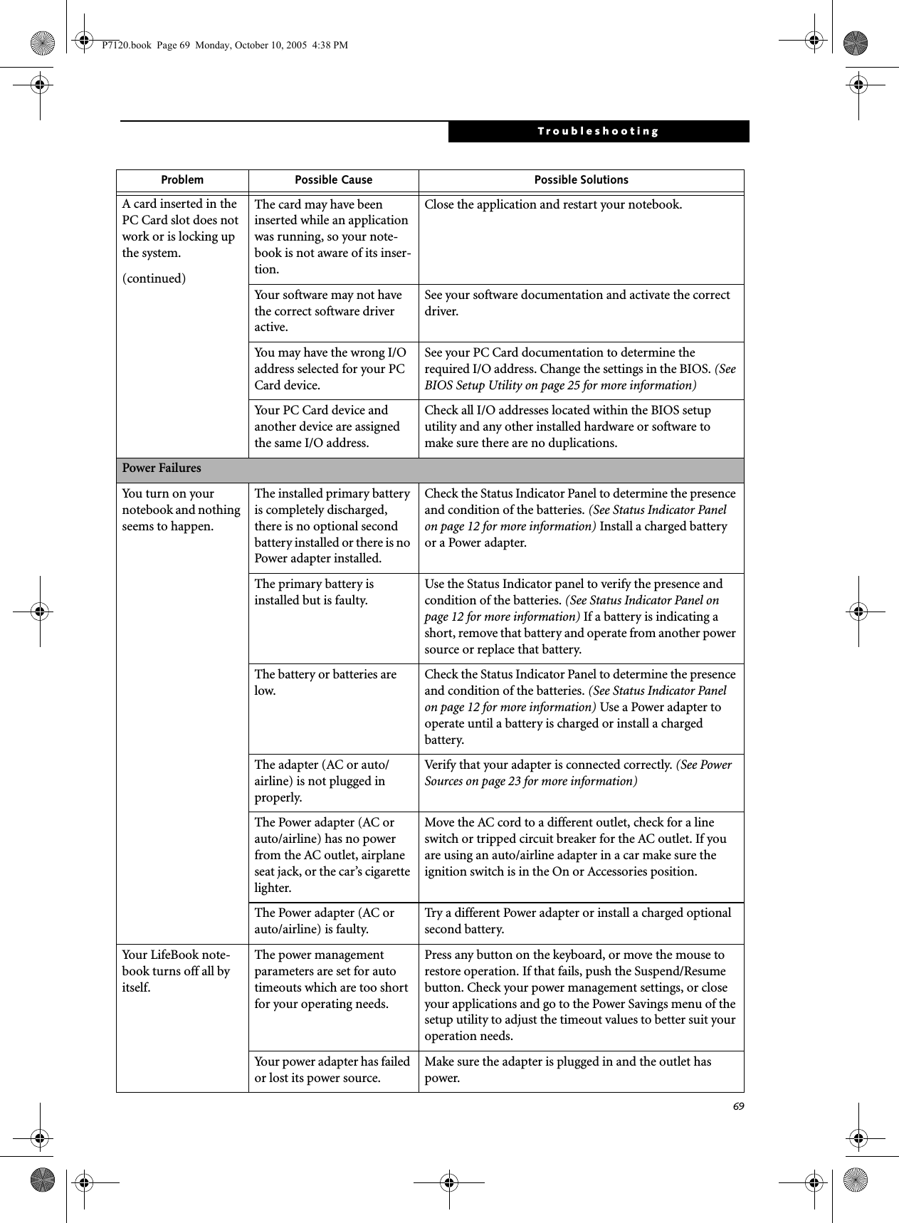
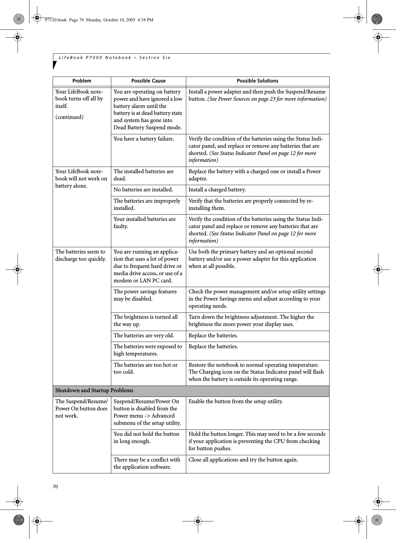
![66LifeBook P7000 Notebook – Section SixTROUBLESHOOTING TABLEProblem PageAudio Problems . . . . . . . . . . . . . . . . . . . . . . . . . . page 66Optical Drive Problems . . . . . . . . . . . . . . . . . . . . page 66Floppy Disk Drive Problems . . . . . . . . . . . . . . . . page 67Hard Drive Problems . . . . . . . . . . . . . . . . . . . . . . page 67Keyboard or Mouse Problems. . . . . . . . . . . . . . . page 67Memory Problems . . . . . . . . . . . . . . . . . . . . . . . . page 68Modem Problems. . . . . . . . . . . . . . . . . . . . . . . . . page 68 Problem PageUSB Device Problems . . . . . . . . . . . . . . . . . . . . . page 68PC Card Problems . . . . . . . . . . . . . . . . . . . . . . . . page 68Power Failures . . . . . . . . . . . . . . . . . . . . . . . . . . . page 69Shutdown and Startup Problems . . . . . . . . . . . . page 70Video Problems . . . . . . . . . . . . . . . . . . . . . . . . . . page 71Miscellaneous Problems . . . . . . . . . . . . . . . . . . . page 72Problem Possible Cause Possible SolutionsAudio ProblemsThere is no sound coming from the built-in speakers.The software volume control is set too low.Adjust the sound volume control settings in your software, operating system and applications. You can also use the [Fn+F9] key combination. Pressing [F9] repeatedly while holding [Fn] will increase the notebook volume.Headphones are plugged into your notebook.Plugging in headphones disables the built-in speakers; remove the headphones.BIOS audio settings are incorrect.Set the BIOS setup utility to the default values within the Multimedia Device Configuration menu. (See BIOS Setup Utility on page 25 for more information)Software driver is not config-ured correctly.Refer to your application and operating system documen-tation for help.Sound may be set to Mute. Click on the Volume icon in the system tray and verify that the Mute checkbox is not set. You can also use the [Fn+F3] key combination. Pressing [F3] while holding [Fn] will toggle the audio Mute on and off.Device Manager may not be set correctly.Go to the Control Panel -> System, and click on the Hard-ware tab. Click the [Device Manager] button and scroll down to “Sound, Video and Game Controllers”. Click the “+” symbol and scroll down the list that appears to see if there is a yellow exclamation point next to any of the items. If there is, you will need to reload the related driver. DVD/CD-RW Drive ProblemsLifeBook notebook fails to recognize disc in optical drive.Protective sheet is still in the optical drive tray.Remove the protective sheet from the tray.The disc is not pushed down onto the center of the drive.Open optical drive tray and re-install the disc properly.Optical drive tray is not latched shut.Push on the front of the optical drive tray until it latches.Incorrect DVD Player or no player software is installed.Install DVD Player software. (See “Using the Optical Drive Software” on page 35 for more information.)Wrong drive designator was used for optical drive in the application.Verify the drive designator used by the application is the same as the one used by the operating system. When the operating system is booted from a DVD/CD, drive designa-tions are automatically adjusted.DVD/CD disc is dirty or defective.Wipe disc with non-abrasive cleaning cloth and reinsert. If it still will not work try a different disc.P7120.book Page 66 Monday, October 10, 2005 4:38 PM](https://usermanual.wiki/Fujitsu-Client-Computing/WB0045.USERS-MANUAL-2/User-Guide-725912-Page-20.png)

![71TroubleshootingThe system powers up, and displays power on information, but fails to load the operating system.Boot sequence settings of the setup utility are not compat-ible with your configuration.Set the operating source by pressing [F12] while the Fujitsu logo is on screen or use the [F2] key and enter the setup utility and adjust the source settings from the Boot menu. (See BIOS Setup Utility on page 25 for more information)You have a secured system requiring a password to load your operating system.Make sure you have the right password. Enter the setup utility and verify the Security settings and modify them as accordingly. (See BIOS Setup Utility on page 25 for more information)Internal hard drive was not detected.Use the BIOS setup utility to try to auto detect the internal hard drive. If this does not work, contact Fujitsu Service and Support at 1-800-8FUJITSU.An error message is displayed on-screen during the notebook (boot) sequence.Power On Self Test (POST) has detected a problem.See the Power On Self Test (POST) messages to determine the meaning and severity of the problem. Not all messages are errors; some are simply status indicators. (See Power On Self Test Messages on page 73 for more information)Your notebook appears to change setup parameters when you start it.BIOS setup changes were not saved when you made them and exited the BIOS setup utility returning it to previous settings.Make sure you select Save Changes And Exit when exiting the BIOS setup utility.The BIOS CMOS hold-up battery has failed.Contact your support representative for repairs. This is not a user serviceable part but has a normal life of 3 to 5 years.Video ProblemsThe built-in display is blank when you turn on your LifeBook notebook.The notebook is set for an external monitor only.Pressing [F10] while holding down the [Fn] key allows you to change your selection of where to send your display video. Each time you press the combination of keys you will step to the next choice. The choices, in order are: built-in display only, external monitor only, both built-in display and external monitor.The display angle and bright-ness settings are not adequate for your lighting conditions.Move the display and the brightness control until you have adequate visibility.Power management timeouts may be set for short intervals and you failed to notice the display come on and go off.Press any button the keyboard, or move the mouse to restore operation. If that fails, push the Suspend/Resume button. (The display may be shut off by Standby mode, Auto Suspend or Video Timeout)The notebook is set for S-Video display only.While holding down the [Fn] key, click on the [F11] key to toggle the S-Video display off.The notebook turned on with a series of beeps and your built-in display is blank.Power On Self Test (POST) has detected a failure which does not allow the display to operate.Contact your support representative.The display goes blank by itself after you have been using it.The notebook has gone into Video timeout, or Standby, Suspend, or Hibernation modes because you have not used it for a period of time.Press any button on the keyboard, or move the mouse to restore operation. If that fails, push the Suspend/Resume button. Check your power management settings to adjust the timeout values to better suit your operation needs. (See BIOS Setup Utility on page 25 for more information)Problem Possible Cause Possible SolutionsP7120.book Page 71 Monday, October 10, 2005 4:38 PM](https://usermanual.wiki/Fujitsu-Client-Computing/WB0045.USERS-MANUAL-2/User-Guide-725912-Page-25.png)
![72LifeBook P7000 Notebook – Section SixThe display goes blank by itself after you have been using it.(continued)The power management timeouts may be set for very short intervals and you failed to notice the display come on and go off.Press any button on the keyboard, or move the mouse to restore operation. If that fails, push the Suspend/Resume button. (The display may be shut off by Standby Mode, Auto Suspend or Video Timeout)The Built-in Display does not close.A foreign object, such as a paper clip, is stuck between the display and the keyboard.Remove all foreign objects from the keyboard.The Built-in Display has bright or dark spots.If the spots are very tiny and few in number, this is normal for a large LCD display.This is normal; do nothing.If the spots are numerous or large enough to interfere with your operation needs.Display is faulty; contact your support representative.The application display uses only a portion of your screen and is surrounded by a dark frame.You are running an applica-tion that does not support 800 x 600/1024 x 768 pixel resolution display and display compression is enabled.Display compression gives a clearer but smaller display for applications that do not support 800 x 600/1024 x 768 pixel resolution. You can fill the screen but have less resolution by changing your display compression setting, (See the Video Features submenu, located within the Advanced menu of the BIOS. (See BIOS Setup Utility on page 25 for more information)The display is dark when on battery power.The default is set on low brightness to conserve power.Press [Fn] + [F7] to increase brightness and adjust Power Control under battery settings.You have connected an external monitor and it does not display any information.Your BIOS setup is not set to enable your external monitor.Toggle the video destination by pressing [Fn] and [F10] together, or check your BIOS setup and enable your external monitor. (See the Video Features submenu, located within the Advanced Menu of the BIOS. (See BIOS Setup Utility on page 25 for more information)Your external monitor is not properly installed. Reinstall your device. (See External Video Port on page 44 for more information)Your operating system soft-ware is not setup with the correct software driver for that device. Check your device and operating system documentation and activate the proper driver.You connected an external monitor but it doesn’t come on.Your external monitor is not compatible with your Life-Book notebook.See your monitor documentation and the External Monitor Support portions of the Specifications section. (See Specifications on page 85 for more information)Miscellaneous ProblemsAn error message is displayed on the screen during the operation of an application.Application software often has its own set of error message displays. See your application manual and help displays screens for more information. Not all messages are errors some may simply be status.Problem Possible Cause Possible SolutionsP7120.book Page 72 Monday, October 10, 2005 4:38 PM](https://usermanual.wiki/Fujitsu-Client-Computing/WB0045.USERS-MANUAL-2/User-Guide-725912-Page-26.png)

![74LifeBook P7000 Notebook – Section Six*Parity Check 2 nnnn Parity error found in the I/O bus. BIOS attempts to locate the address and display it on the screen. If it cannot locate the address, it displays ????. This is apotentially data-destroying failure. Contact yoursupport representative.*Press <F1> to resume, <F2> to SETUP Displayed after any recoverable error message. Pressthe [F1] key to continue the boot process or the [F2]key to enter Setup and change any settings.*Previous boot incomplete – Default configuration used Previous Power On Self Test did not complete success-fully. The Power On Self Test will load default values and offer to run Setup. If the previous failure was caused by incorrect values and they are not corrected, the next boot will likely fail also. If using the default settings does not allow you to complete a successful boot sequence, you should turn off the power and contact your support representative.*Real time clock error Real-time clock fails BIOS test. May require board repair. Contact your support representative.*Shadow RAM Failed at offset: nnnn Shadow RAM failed at offset nnnn of the 64k block at which the error was detected. You are risking data corrup-tion if you continue. Contact your support representative.nnnn Shadow RAM Passed Where nnnn is the amount of shadow RAM in kilobytes successfully tested.*System battery is dead – Replace and run SETUP The BIOS CMOS RAM memory hold up battery is dead. This is part of your BIOS and is a board mounted battery which requires a support representative to change. You can continue operating but you will have to use setup utility default values or reconfigure your setup utility every time you turn off your notebook. This battery has an expected life of 2 to 3 years.System BIOS shadowed System BIOS copied to shadow RAM.*System CMOS checksum bad – run SETUP BIOS CMOS RAM has been corrupted or modified incorrectly, perhaps by an application program that changes data stored in BIOS memory. Run Setup and reconfigure the system.*System RAM Failed at offset: nnnn System memory failed at offset nnnn of in the 64k block at which the error was detected. This means that there is a fault in your built-in memory. If you continue to operate, you risk corrupting your data. Contact your support representative for repairs.nnnn System RAM PassedWhere nnnn is the amount of system memory inkilobytes successfully tested.*System timer error The timer test failed. The main clock that operates the computer is faulty. Requires repair of system board. Contact your support representative for repairs.UMB upper limit segment address: nnnn Displays the address of the upper limit of Upper Memory Blocks, indicating released segments of the BIOS memory which may be reclaimed by a virtual memory manager.Video BIOS shadowed Video BIOS successfully copied to shadow RAM.EMERGENCY DVD TRAY RELEASEIf for some reason the eject button fails, you can open the DVD/CD-RW tray with a paper clip or similar tool inserted into the eject hole in the far right side of the front of the tray. Straighten one side of a paper clipand push it gently into the hole. The tray will pop outa short distance.MODEM RESULT CODESThe operating system and application software that is factory installed detects the modem characteristics and provides the necessary command strings to operate the modem. The internal modem operation is controlled by generic AT commands from the operating system and application software. The standard long form result codes may, in some cases, be displayed on your screen to keep you informed of the actions of your modem. The operating system and application software may suppress display of the result codes. Examples of result codes are:■OK■NO CARRIER■NO DIALTONE■CONNECT 53000 (Connection complete at 53,000 bps.)■ERROR■FAX■RING (This means an incoming call.)■BUSY■NO ANSWERWhen using the internal modem with applicationsthat are not factory installed refer to theapplication documentation.P7120.book Page 74 Monday, October 10, 2005 4:38 PM](https://usermanual.wiki/Fujitsu-Client-Computing/WB0045.USERS-MANUAL-2/User-Guide-725912-Page-28.png)
![75TroubleshootingRestoring Your Pre-installed SoftwareThe Drivers and Applications Restore (DAR) CD contains sets of device drivers and Fujitsu utilities (in specific directories) that are unique to your notebook configuration for use as documented below.Re-Installing Individual Drivers and Applications The Drivers and Applications CD can be used to selec-tively re-install drivers and/or applications that may have been un-installed or corrupted. To re-install drivers and/or applications:1. Boot up the system and insert the DAR CD after Windows has started. A Fujitsu Installer screen is displayed after the CD is inserted.2. After reading the License Agreement, click [I agree].3. A window will appear containing a list of applica-tions, drivers, and utilities that you can install from the Drivers and Applications CD.4. In the list, check off all the components you want to install. If you want to install all components, click [Select All]. Clicking [Select All] will select all of the blue-coded components; you must select grey and green components separately.5. Once you have selected the components you wish to install, click [Install Selected Subsystems]; the components will be installed.6. After the components are installed, click [OK], then click [Yes] when asked if you want to reboot the system. RESTORING THE FACTORY IMAGEThe Restore Disc that came with your system contains two utilities:■The Recovery utility allows you to restore the original contents of the C: drive.■The Hard Disk Data Delete utility on this disc is used to delete all data on your hard disk and prevent it from being reused. Do not use the Hard Disk Data Delete utility unless you are absolutely certain that you want to erase your entire hard disk, including all partitions.BOOT Priority ChangeBefore restoring an image, you must first verify that your system is set up to boot from the DVD drive. To verify/change the boot-up priority (rather than booting-up from the hard drive or an external floppy disk drive), perform the following steps:1. Start your system and press the [F2] key when the Fujitsu logo appears. You will enter the BIOS Setup Utility.2. Using the arrow keys, go to the Boot menu.3. Arrow down to the Boot Device Priority submenu. Press [Enter].4. If “Optical Media Drive” or “CD-ROM Drive” is not at the top of the list, arrow down to the drive in the list, and press the space bar (or the + key) to move it to the top of the list. (The system attempts to boot from the devices in the order in which they are listed.). Note that the BIOS for some systems will indicate “CD-ROM Drive”, even when a DVD drive is connected.5. If you have an external DVD drive connected, proceed to step 6; otherwise, proceed to step 7.6. If you have an external DVD drive connected:• Select the Advanced menu in the BIOS window.• Scroll down to the USB Features submenu and press the Enter key to open it.If you have access to the internet, visit the Fujitsu Support web site at http://www.computers.us.fujitsu.com/support to check for the most current information, drivers and hints on how to perform recovery and system updates. (See Automatically Downloading Driver Updates on page 76 for more information)There may be certain free third-party applications pre-installed on your system that are not on the DAR CD. The latest versions of the applications can be downloaded from the third-party’s website.The components listed are color-coded in terms of their install status. Blue indicates that the component can be installed. Green indicates that the component needs to be installed separately. Grey indicates a component that is already installed; grey items can be reinstalled, but prior to installation you will receive a reminder that the component is already installed. • The use of this disc requires that you have a device capable of reading DVDs attached to your system. If you do not have a built-in DVD player, you will need to attach an external player. For more information on available external devices, visit our Web site at: us.fujitsu.com/computers. • This disc can only be used with the system with which it was purchased.P7120.book Page 75 Monday, October 10, 2005 4:38 PM](https://usermanual.wiki/Fujitsu-Client-Computing/WB0045.USERS-MANUAL-2/User-Guide-725912-Page-29.png)
![76LifeBook P7000 Notebook – Section Six• If Legacy USB Support is disabled, press the space bar to enable it.• Scroll down to SCSI SubClass Support and press the space bar to enable it. 7. Press [F10], then click on [Yes] to exit the BIOS Setup Utility and return to the boot process.After you have changed the boot priority, you can restore a backup image when you are booting up.Procedure1. Turn on the power to your system.2. Ensure that you have a device that can read DVDs either installed in your system or attached exter-nally to it.3. Insert the Restore Disc into the drive tray.4. Reboot your system.5. After the system reboots, follow the instructions that appear to either restore your system image or erase all data from your hard disk.AUTOMATICALLY DOWNLOADING DRIVER UPDATESYour system has a convenient tool called the Fujitsu Driver Update (FDU) utility. With FDU, you can choose to automatically or manually go to the Fujitsu site to check for new updates for your system.The FDU icon should appear in the system tray at the bottom right of your screen (roll the cursor over the icons to find the correct one). If the FDU icon does not appear in the system tray, it can be started by going to [Start] -> All Programs, and clicking on Fujitsu Driver Update; this will create the icon automatically.To invoke the FDU menu, right-click on the FDU icon. The menu contains the following items:■Check for updates nowAllows for manual driver update search. The first time it is used, you are prompted to agree to a user agreement. After clicking on the icon, the FDU auto-matically connects with the Fujitsu site to check for updates and downloads them. While downloading, the icon has a red bar through it, indicating that it cannot be used while the download is in process. When the update is complete, a message appears informing you of the fact.■Enable Automatic Update NotificationsAutomatically searches for new updates on a regular basis (approximately every 3 days).■Show update historyBrings up a screen that displays a history of updates that have been made via the FDU.■About Fujitsu Driver UpdateDisplays the FDU version number and copyright information■Fujitsu Driver Update ReadmeDisplays the FDU readme.P7120.book Page 76 Monday, October 10, 2005 4:38 PM](https://usermanual.wiki/Fujitsu-Client-Computing/WB0045.USERS-MANUAL-2/User-Guide-725912-Page-30.png)


![86LifeBook P7000 Notebook – Section EightTheft Prevention Lock SlotSlot for use with physical restraining security systems. DEVICE PORTS■PC Card slot for one Type II card: PCMCIA Standard 2.1 with CardBus support■One connector for external monitor (see Display specifications)■One Memory Stick/SD/xD slot■Three USB 2.0 connectors for input/output devices■One S-Video Out port■One modular modem (RJ-11) connector■One LAN (RJ-45) port■One IEEE 1394 port■One stereo headphone/line-out jack. (See Audio speci-fications)■One mono microphone jack. (See Audio specifications)KEYBOARDBuilt-in keyboard with all functions of 101 key keyboards.■Total number of keys: 82■Function keys: [F1] through [F12]■Feature extension key: [Fn]■Two Windows keys: one Start and one application key ■Key pitch: 17.5 mm■Key stroke: 2 mm■Built-in Touchpad pointing device with left and right buttons and scroll button.■Built-in palm restExternal Keyboard SupportUSB-compatibleExternal Mouse SupportUSB-compatiblePOWERBatteries■One standard 4-cell high-capacity Lithium ion battery, rechargeable, 7.2V, 5200 mAh■Optional high-capacity 6-cell Lithium ion battery, rechargeable, 7.2V, 7800 mAh■Optional second bay battery: 4-cell Lithium ion battery, rechargeable, 10.8V, 2300 mAhAC AdapterAutosensing 100-240V AC, 60W, supplying 16V DC, 3.75A to the LifeBook notebook, which includes an AC cable.Power ManagementConforms to ACPI (Advanced Configuration and Power Interface)DIMENSIONS AND WEIGHTOverall DimensionsApproximately 10.28"(w) x 7.83"(d) x 1.26/1.43"(h) (261mm x 199 mm x 32/36 mm)WeightsApproximately 3.0 lbs (1.50 kg) with standard battery and DVD/CD-RW combo driveENVIRONMENTAL REQUIREMENTSTemperatureOperating: 41° to 95° F (5° to 35° C)Non-operating: 5° to 140° F (–15° to 60° C)HumidityOperating: 20% to 85%, relative, non-condensingNon-operating; 8% to 85%, relative, non-condensingAltitudeOperating: 10,000 feet (3,048 m) maximumPOPULAR ACCESSORIESFor ordering or additional information on Fujitsu accessories please visit our Web site at:www.shopfujitsu.com or call 1-800-FUJITSU.P7120.book Page 86 Monday, October 10, 2005 4:38 PM](https://usermanual.wiki/Fujitsu-Client-Computing/WB0045.USERS-MANUAL-2/User-Guide-725912-Page-40.png)


![100LifeBook P7000 Notebook – AppendixThe installation program automatically places an icon (Softex OmniPass) in the Windows Control Panel as well as a golden key shaped icon in the taskbar. Verifying Information about OmniPassAfter you have completed installing OmniPass and restarted your system, you may wish to check the version of OmniPass on your system.To check the version information of OmniPass:1. From the Windows Desktop, double-click the key-shaped OmniPass icon in the taskbar (usually located in the lower right corner of the screen),or,Click the Start button, select Settings, and click Control Panel (if you are using Windows XP you will see the Control Panel directly in the Start menu; click it, then click Switch to Classic View). Double-click Softex OmniPass in the Control Panel, and the OmniPass Control Center will appear. If it does not appear, then the program is not properly installed,or,Click the Start button, select Programs, and from the submenu select the Softex program group, from that submenu click OmniPass Control Center.2. Select the About tab at the top of the OmniPass Control Panel. The About tab window appears with version information about OmniPass.Uninstalling OmniPassTo remove the OmniPass application from your system:1. Click Start on the Windows taskbar. Select Settings, and then Control Panel.2. Double-click Add/Remove Programs.3. Select OmniPass, and then click Change/Remove.4. Follow the directions to uninstall the OmniPass application.5. Once OmniPass has finished uninstalling, reboot your system when prompted.USER ENROLLMENTBefore you can use any OmniPass features you must first enroll a user into OmniPass.Master Password ConceptComputer resources are often protected with passwords. Whether you are logging into your computer, accessing your email, e-banking, paying bills online, or accessing network resources, you often have to supply credentials to gain access. This can result in dozens of sets of creden-tials that you have to remember.During OmniPass user enrollment a "master password” is created for the enrolled user. This master password “replaces” all other passwords for sites you register with OmniPass. Example: A user, John, installs OmniPass on his system (his home computer) and enrolls an OmniPass user with username “John_01” and password “freq14”. He then goes to his webmail site to log onto his account. He inputs his webmail credentials as usual (username “John_02” and password “lifebook”), but instead of clicking [Submit], he directs OmniPass to Remember Password. Now whenever he returns to that site, OmniPass will prompt him to supply access credentials. John enters his OmniPass user credentials (“John_01” and “freq14”) in the OmniPass authentication prompt, and he is allowed into his webmail account. He can do this with as many web sites or password protected resources he likes, and he will gain access to all those sites with his OmniPass user credentials (“John_01” and “freq14”). This is assuming he is accessing those sites with the system onto which he enrolled his OmniPass user. OmniPass does not actually change the credentials of the password protected resource. If John were to go to an Internet cafe to access his webmail, he would need to enter his original webmail credentials (“John_02” and “lifebook”) to gain access. If he attempts his OmniPass user credentials on a system other than where he enrolled that OmniPass user, he will not gain access.Basic EnrollmentThe Enrollment Wizard will guide you through the process of enrolling a user. Unless you specified other-wise, after OmniPass installation the Enrollment Wizard will launch on Windows login. If you do not see the Enrollment Wizard, you can bring it up by clicking Start on the Windows taskbar; select Programs; select Softex; click OmniPass Enrollment Wizard.1. Click Enroll to proceed to username and password verification. By default, the OmniPass Enrollment Wizard enters the credentials of the currently logged in Windows user.2. Enter the password you use to log in to Windows. This will become the “master password” for this OmniPass user. In most cases, the Domain: value For uninstallation, OmniPass requires that the user uninstalling OmniPass have administrative privileges to the system. If your current user does not have administrative privileges, log out and then log in with an administrator user before proceeding with OmniPass uninstallation.The enrollment procedure assumes you have no hardware authentication devices or alternate storage locations that you wish to integrate with OmniPass. If you desire such functionality, consult the appropriate sections of this document.P7120.book Page 100 Monday, October 10, 2005 4:38 PM](https://usermanual.wiki/Fujitsu-Client-Computing/WB0045.USERS-MANUAL-2/User-Guide-725912-Page-54.png)
![101Using the Fingerprint Sensorwill be your Windows computer name. In a corpo-rate environment, or when accessing corporate resources, the Domain: may not be your Windows computer name. Click [Next] to continue.3. In this step OmniPass captures your fingerprint. Refer to “Enrolling a Fingerprint” on page 101 for additional information.4. Next, choose how OmniPass notifies you of various events. We recommend you keep Taskbar Tips on Beginner mode taskbar tips and Audio Tips on at least Prompt with system beeps only until you get accustomed to how OmniPass operates. Click [Next] to proceed with user enrollment. You will then see a Congratulations screen indicating your completion of user enrollment.5. Click [Done] to exit the OmniPass Enrollment Wizard. You will be asked if you’d like to log in to OmniPass with your newly enrolled user; click [Yes].Enrolling a FingerprintEnrolling a fingerprint will increase the security of your system and streamline the authentication procedure. You enroll fingerprints in the OmniPass Control Center. With an OmniPass user logged in, double-click the system tray OmniPass icon. Select the User Settings tab and click Enrollment under the User Settings area. Click Enroll Authentication Device and authenticate at the authentication prompt to start device enrollment.1. During initial user enrollment, you will be prompted to select the finger you wish to enroll. Fingers that have already been enrolled will be marked by a green check. The finger you select to enroll at this time will be marked by a red arrow. OmniPass will allow you re-enroll a finger. If you choose a finger that has already been enrolled and continue enrollment, OmniPass will enroll the fingerprint, overwriting the old fingerprint. Select a finger to enroll and click [Next].2. It is now time for OmniPass to capture your selected fingerprint. It may take a several capture attempts before OmniPass acquires your fingerprint. Should OmniPass fail to acquire your fingerprint, or if the capture screen times out, click [Back] to restart the fingerprint enrollment process. Your system has a “swipe” fingerprint sensor. A swipe sensor is small and resembles a skinny elon-gated rectangle. To capture a fingerprint, gently swipe or pull your fingertip over the sensor (starting at the second knuckle) towards yourself. Swiping too fast or too slow will result in a failed capture. The Choose Finger screen has a [Practice] button; click it to practice capturing your fingerprint. When you are comfortable with how your fingerprint is captured, proceed to enroll a finger.3. Once OmniPass has successfully acquired the finger-print, the Ver i fy Fin g erp r int screen will automati-cally appear. To verify your enrolled fingerprint, place your fingertip on the sensor and hold it there as if you were having a fingerprint captured. Successful fingerprint verification will show a green fingerprint in the capture window and the text Ve r i-fication Successful under the capture window.USING OMNIPASSYou are now ready to begin using OmniPass. Used regu-larly, OmniPass will streamline your authentications.Password ReplacementYou will often use the password replacement function. When you go to a restricted access website (e.g., your bank, your web-based email, online auction or payment sites), you are always prompted to enter your login credentials. OmniPass can detect these prompts and you can teach OmniPass your login credentials. The next time you go to that website, you can authenticate with your fingerprint to gain access.OmniPass Authentication ToolbarAfter installing OmniPass and restarting, you will notice a dialog you have not seen before at Windows Logon. This is the OmniPass Authentication Toolbar, and it is displayed whenever the OmniPass authentication system is invoked. The OmniPass authentication system may be invoked frequently: during Windows Logon, during OmniPass Logon, when unlocking your workstation, when resuming from standby or hibernate, when unlocking a password-enabled screensaver, during pass-word replacement for remembered site or application logins, and more. When you see this toolbar, OmniPass is prompting you to authenticate.The Logon Authentication window indicates what OmniPass-restricted function you are attempting. The icons in the lower left (fingerprint and key) show what authentication methods are available to you. Selected authentication methods are highlighted while unselected methods are not. When you click the icon for an unse-lected authentication method, the authentication prompt associated with that method is displayed.When prompted to authenticate, you must supply the appropriate credentials: an enrolled finger for the finger-print capture window or your master password for the master password prompt (the key icon).Remembering a PasswordOmniPass can remember any application, GUI, or pass-word protected resource that has a password prompt.Using the following procedure, you can store a set of credentials into OmniPass. These credentials will then be linked to your “master password” or fingerprint.P7120.book Page 101 Monday, October 10, 2005 4:38 PM](https://usermanual.wiki/Fujitsu-Client-Computing/WB0045.USERS-MANUAL-2/User-Guide-725912-Page-55.png)
![102LifeBook P7000 Notebook – AppendixGo to a site that requires a login (username and pass-word), but do not log in yet. At the site login prompt, enter your username and password in the prompted fields, but do not enter the site (do not hit [Enter], [Submit], [OK], or Login). Right-click the OmniPass system tray icon and select Remember Password from the submenu. The Windows arrow cursor will change to a golden key OmniPass cursor. Click this OmniPass cursor in the login prompt area, but do not click the [Login] or [Submit] button.Associating a Friendly NameAfter clicking the OmniPass key cursor near the login prompt, OmniPass will prompt you to enter a “friendly name” for this site. You should enter something that reminds you of the website, the company, or the service you are logging into. In its secure database, OmniPass associates this friendly name with this website.Additional Settings for Remembering a SiteWhen OmniPass prompts you to enter a “friendly name” you also have the opportunity to set how OmniPass authenticates you to this site. There are three effective settings for how OmniPass handles a remembered site.The default setting is Automatically click the “OK” or “Submit” button for this password protected site once the user is authenticated. With this setting, each time you navigate to this site OmniPass will prompt you for your master password or fingerprint authentication device. Once you have authenticated with OmniPass, you will automatically be logged into the site. Less secure is the option to Automatically enter this password protected site when it is activated. Do not prompt for authentication. Check the upper box to get this setting, and each time you navigate to this site OmniPass will log you into the site without prompting you to authenticate.If you uncheck both boxes in Settings for this Password Site, OmniPass will prompt you for your master pass-word or fingerprint authentication device. Once you have authenticated with OmniPass your credentials will be filled in to the site login prompt, but you will have to click the website [OK], [Submit], or [Login] button to gain access to the site. Click Finish to complete the remember password proce-dure. The site location, the credentials to access the site, and the OmniPass authentication settings for the site are now stored in the OmniPass secure database. The OmniPass authentication settings (Settings for this Pass-word Site) can always be changed in Vault Management.Logging in to a Remembered SiteWhether or not OmniPass prompts you to authenticate when you return to a remembered site is determined by Settings for this Password Site and can be changed in Vault Management. The following cases are applicable to using OmniPass to login to: Windows, remembered web sites, and all other password protected resources.With Master PasswordOnce you return to a site you have remembered with OmniPass, you may be presented with a master pass-word prompt. Enter your master password and you will be allowed into the site.Logging into Windows with a Fingerprint DeviceWhen logging into Windows with a fingerprint device, the fingerprint capture window will now appear next to the Windows Login screen. Place your enrolled fingertip on the sensor to authenticate. You will be simultaneously logged into Windows and OmniPass. The capture window will also appear if you have used Ctrl-Alt-Del to lock a system, and the fingerprint device can be used to log back in as stated above.In Windows XP, your login options must be set either for classic login, or for fast user switching and logon screen to be enabled to use your fingerprint to log on to Windows. To change this go to Control Panel, select User Accounts and then click Change the way users log on or off. If your Windows screensaver is password protected, the fingerprint capture window will now appear next to screensaver password dialog during resume. You can authenticate to your screensaver pass-word prompt with your enrolled finger.Password ManagementOmniPass provides an interface that lets you manage your passwords. To access this GUI, double-click the OmniPass key in the system tray. Click Va u l t Ma n a g e -ment; you will be prompted to authenticate. Once you gain access to Vault Management, click Manage Pass-words under Vault Settings. You will see the Manage Passwords interface, with a list of friendly names.This setting is more convenient in that whenever you go to a site remembered with this setting, you will bypass any authentication procedure and gain instant access to the site. But should you leave your system unattended with your OmniPass user logged in, anyone using your system can browse to your password protected sites and gain automatic access.If a machine is locked and OmniPass detects a different user logging back in with a fingerprint, the first user will be logged out and the second user logged in.P7120.book Page 102 Monday, October 10, 2005 4:38 PM](https://usermanual.wiki/Fujitsu-Client-Computing/WB0045.USERS-MANUAL-2/User-Guide-725912-Page-56.png)
![103Using the Fingerprint SensorYou can view the credentials stored for any remembered website by highlighting the desired resource under Pass-word Protected Dialog and clicking Unmask Values. Should a password be reset, or an account expire, you can remove stored credentials from OmniPass. Highlight the desired resource under Password Protected Dialog and click Delete Page. You will be prompted to confirm the password deletion.The two check boxes in Manage Passwords govern whether OmniPass prompts you to authenticate or directly logs you into the remembered site.OmniPass will overwrite an old set of credentials for a website if you attempt to use Remember Password on an already remembered site. The exception to the above rule is the resetting of your Windows password. If your password is reset in Windows, then the next time you login to Windows, OmniPass will detect the password change and prompt you to “Update” or “Reconfirm” your password with OmniPass. Enter your new Windows password in the prompt(s) and click OK and your OmniPass "master password" will still be your Windows password.OmniPass User IdentitiesIdentities allow OmniPass users to have multiple accounts to the same site (e.g., bob@biblomail.com and boballen@biblomail.com). If OmniPass did not provide you identities, you would be limited to remembering one account per site.To create and manage identities, double-click the OmniPass key in the system tray. Click Vau lt Ma n a g e -ment; OmniPass will prompt you to authenticate. Once you gain access to Vault Management, click Manage Identities under Vault Settings. You can only manage the identities of the currently logged in OmniPass userTo add a new identity, click New Identity or double-click Click here to add a new identity. Name the new identity and click [OK], then click [Apply]. You can now switch to the new identity and start remembering passwords.To delete an identity, highlight the identity you want to delete and click [Delete Identity], then click [Apply].To set the default identity, highlight the identity you want as default and click [Set as Default]; click [Apply] to ensure the settings are saved. If you log in to OmniPass with a fingerprint device, you will automati-cally be logged in to the default identity for that OmniPass user. You can choose the identity with which you are logging in if you login using "master password".Choosing User Identity during LoginTo choose your identity during login, type your user-name in the User Name: field. Press [Tab] and see that the Domain: field self-populates. Click the Password: field to bring the cursor to it, and you will see the pull-down menu in the Identity: field. Select the identity you wish to login as and then click OK to login.Switch User IdentityTo switch identities at any time, right-click the OmniPass system tray icon and click Switch User Iden-tity from the submenu. The Switch Identity dialog will appear. Select the desired identity and then click OK.Identities and Password ManagementOn the Manage Passwords interface of the Va u l t Management tab of the OmniPass Control Center, there is a pull-down selection box labeled, Identity. This field lets you choose which identity you are managing pass-words for. When you select an identity here, only those password protected dialogs that are associated with that identity are shown. You can perform all the functions explained in “Password Management” on page 102.CONFIGURING OMNIPASSThis section gives an overview of both the Export/Import function and the OmniPass Control Center. Exporting and Importing UsersUsing the OmniPass Control Center, you can export and import users in and out of OmniPass. The export process backs up all remembered sites, credentials, and any enrolled fingerprints for an OmniPass user. All OmniPass data for a user is backed up to a single encrypted database file. During the import process, the Windows login of the exported user is required. If the proper credentials cannot be supplied, the user profile will not be imported. When you delete an identity, all of its associated remembered sites and password protected dialogs are lost.■You should periodically export your user profile and store it in a safe place. If anything happens to your system, you can import your OmniPass profile to a new system and have all your remem-bered settings and fingerprints instantly.■You don't forget the Windows login credentials when exporting. When you examine the importation, you are prompted for authentication. The credentials that will allow a user profile to be imported are the Windows login credentials of the exported user. They are the credentials that had to be submitted when the user profile was exported. You will need User Name, Password, and Domain.P7120.book Page 103 Monday, October 10, 2005 4:38 PM](https://usermanual.wiki/Fujitsu-Client-Computing/WB0045.USERS-MANUAL-2/User-Guide-725912-Page-57.png)