Fujitsu Client Computing WB0047 LIFEBOOK T4220 SERIES W/ 4965AGN WLAN & EYTF3CSFT User Manual USERS MANUAL
Fujitsu Limited LIFEBOOK T4220 SERIES W/ 4965AGN WLAN & EYTF3CSFT USERS MANUAL
UserManual.wiki
>
Fujitsu Client Computing
>
WB0047 User Manual
USERS MANUAL
Navigation menu
Upload a User Manual
Namespaces
Wiki Guide
HTML
PDF
Info
Views
User Manual
Discussion / Help
Navigation
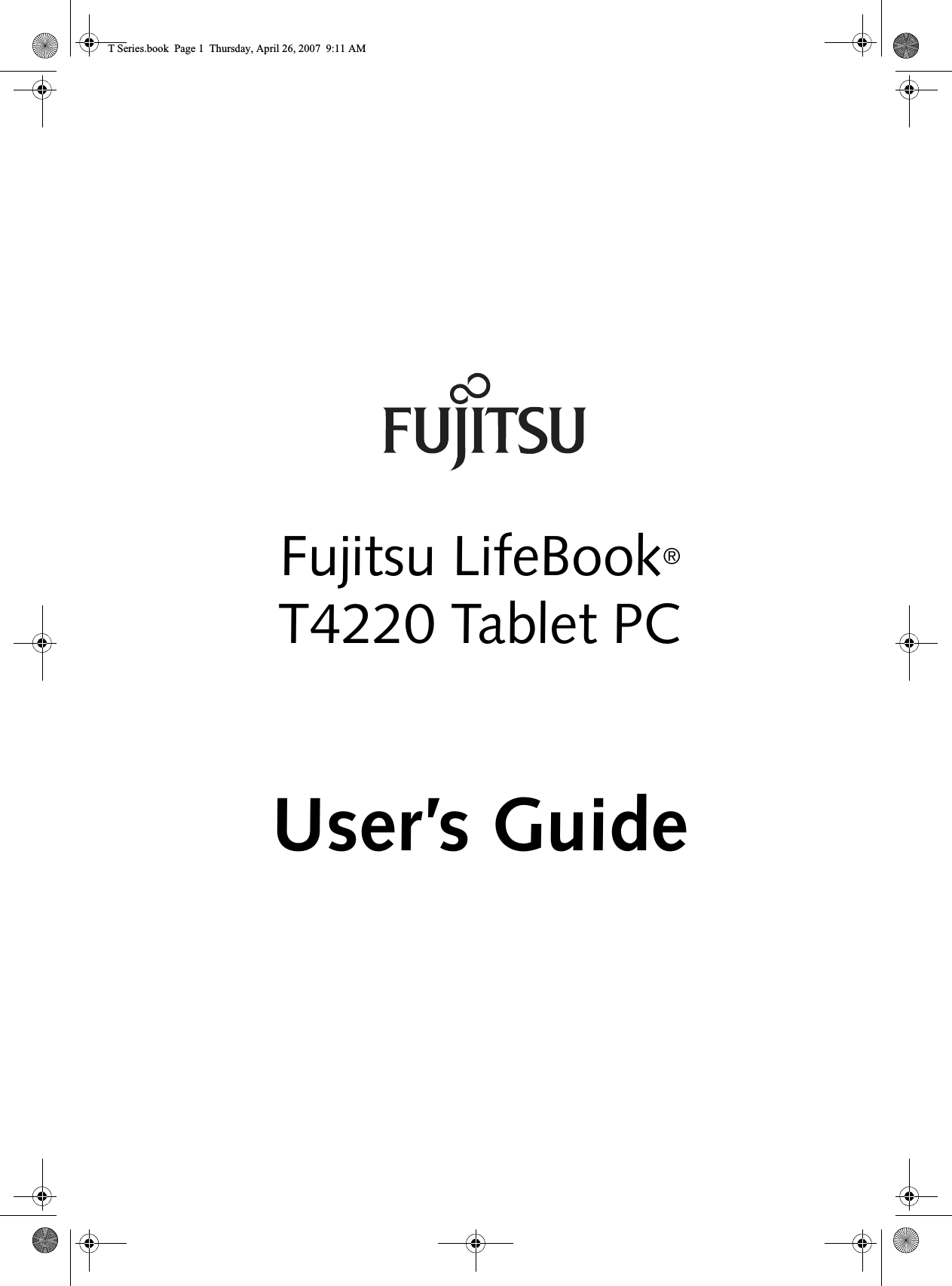


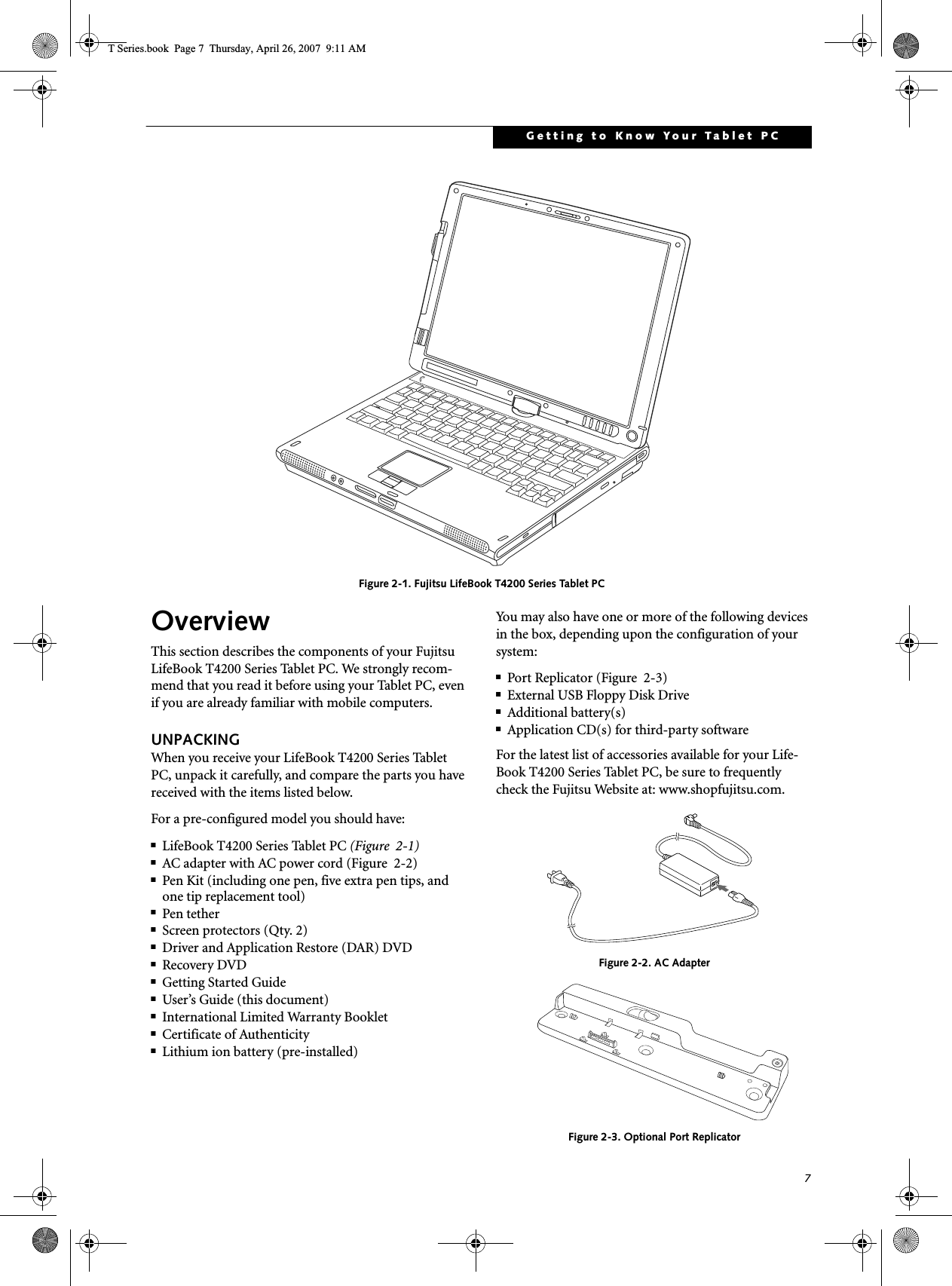
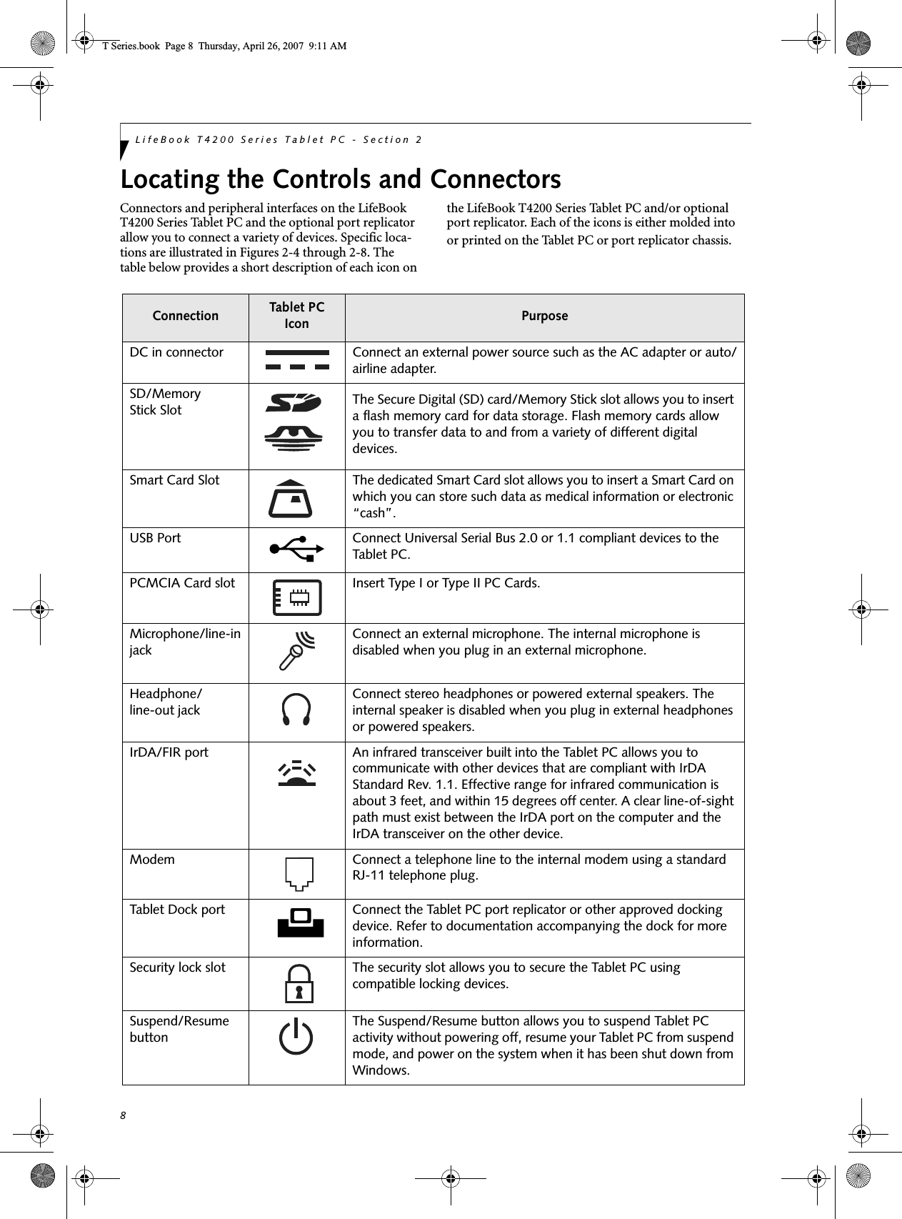
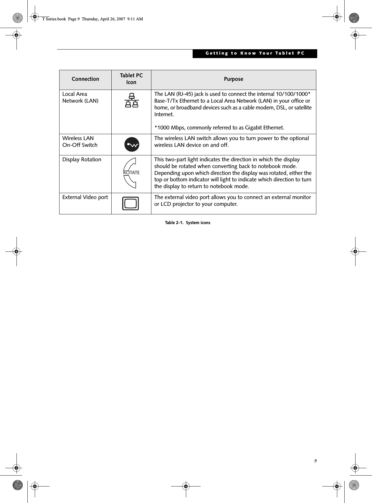
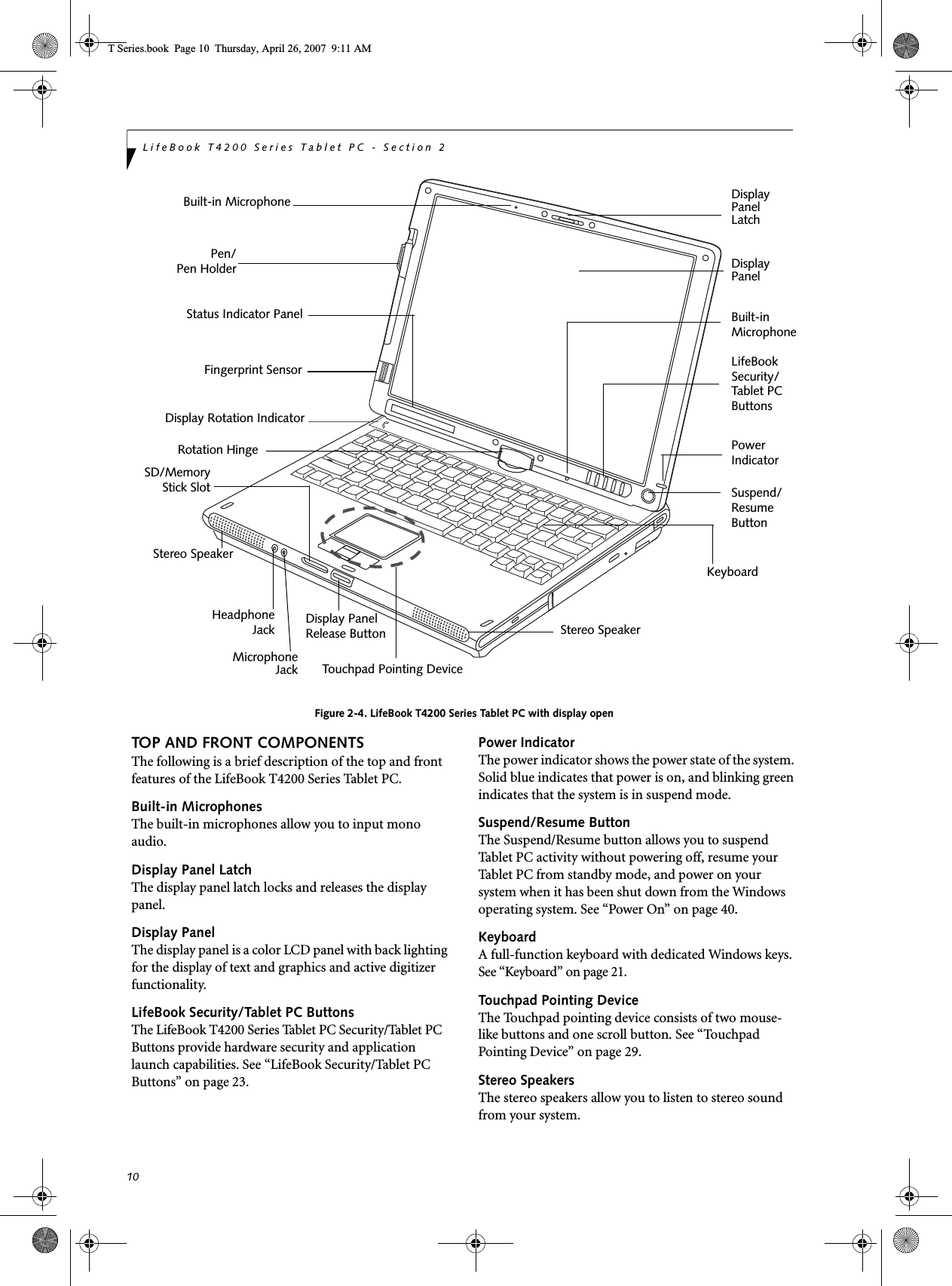
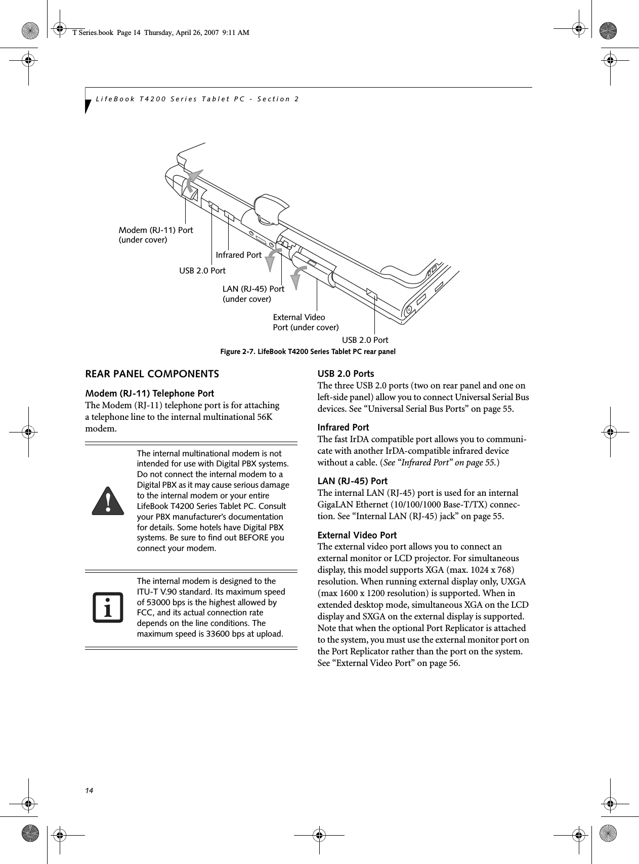
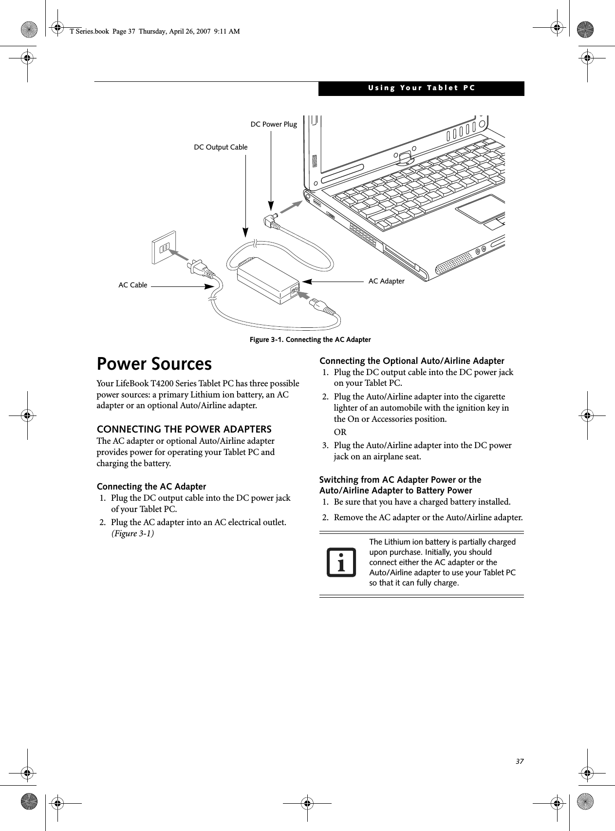
![3PrefacePrefaceABOUT THIS GUIDEThe LifeBook® T4200 Series Tablet PC from Fujitsu Computer Systems Corporation is a powerful convert-ible computer. It can be used either as a standard note-book using keyboard input, or in tablet configuration using pen input. It is powered by a fast, Intel® Core™ 2 Duo processor, has a built-in color display with an active digitizer, and brings the computing power of desktop personal computers (PCs) to a portable and versatile environment.This manual explains how to operate your LifeBook T4200 Series Tablet PC’s hardware and built-in system software. Your LifeBook T4200 Series Tablet PC comes with Windows® XP Tablet PC Edition 2005 or Windows Vista™ Business pre-installed.Your LifeBook T4200 Series Tablet PC is a completely self-contained unit with an active-matrix (TFT) color LCD display. The display has a wide viewing angle and can be used indoors or outdoors. The tablet has a powerful interface that enables it to support a variety of optional features.Conventions Used in the GuideKeyboard keys appear in brackets. Example: [Fn], [F1], [Esc], [Enter] and [Ctl].Pages with additional information about a specific topic are cross-referenced within the text.Example: (See page xx.)On screen buttons or menu items appear in bold.Example: Click OK to restart your Tablet PC.FUJITSU CONTACT INFORMATIONService and SupportYou can contact Fujitsu Computer Systems Service and Support the following ways:■Toll free: 1-800-8Fujitsu (1-800-838-5487)■E-mail: 8fujitsu@us.fujitsu.com ■Website: http://www.computers.us.fujitsu.com/supportBefore you place the call, you should have the following information ready so that the customer support representative can provide you with the fastest possible solution:■Product name■Product configuration number■Product serial number■Purchase date■Conditions under which the problem occurred■Any error messages that have occurred■Type of device connected, if anyFujitsu OnlineYou can go directly to the online Fujitsu Product catalog for your LifeBook notebook by going to:www.shopfujitsu.com.You can also reach Fujitsu Service and Support online by clicking on the Service and Support Website URL link, located in the Fujitsu Web links -> Service and Support Software folder of the Windows Start menu.WARRANTYYour LifeBook T4200 Series Tablet PC is backed by an International Limited Warranty and includes toll-free technical support. Check the service kit that came with your Tablet PC for warranty terms and conditions.The information icon highlights information that will enhance your understanding of the subject material.The caution icon highlights information that is important to the safe operation of your computer, or to the integrity of your files. Please read all caution information carefully.The warning icon warns you about possible hazards that can occur to you, your system, or your files. Please read all warning information carefully.You must have an active internet connection to use the online URL links.T Series.book Page 3 Thursday, April 26, 2007 9:11 AM](https://usermanual.wiki/Fujitsu-Client-Computing/WB0047/User-Guide-790092-Page-12.png)


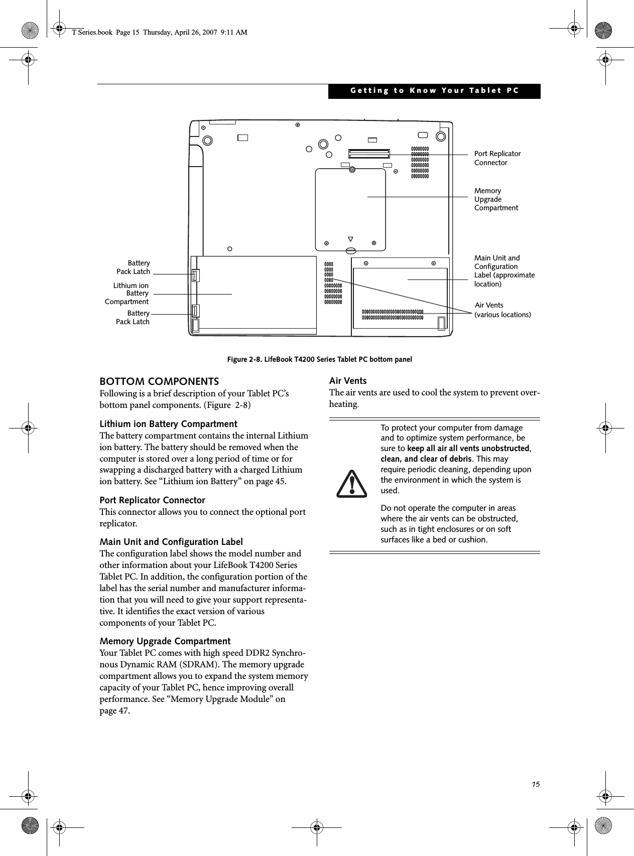
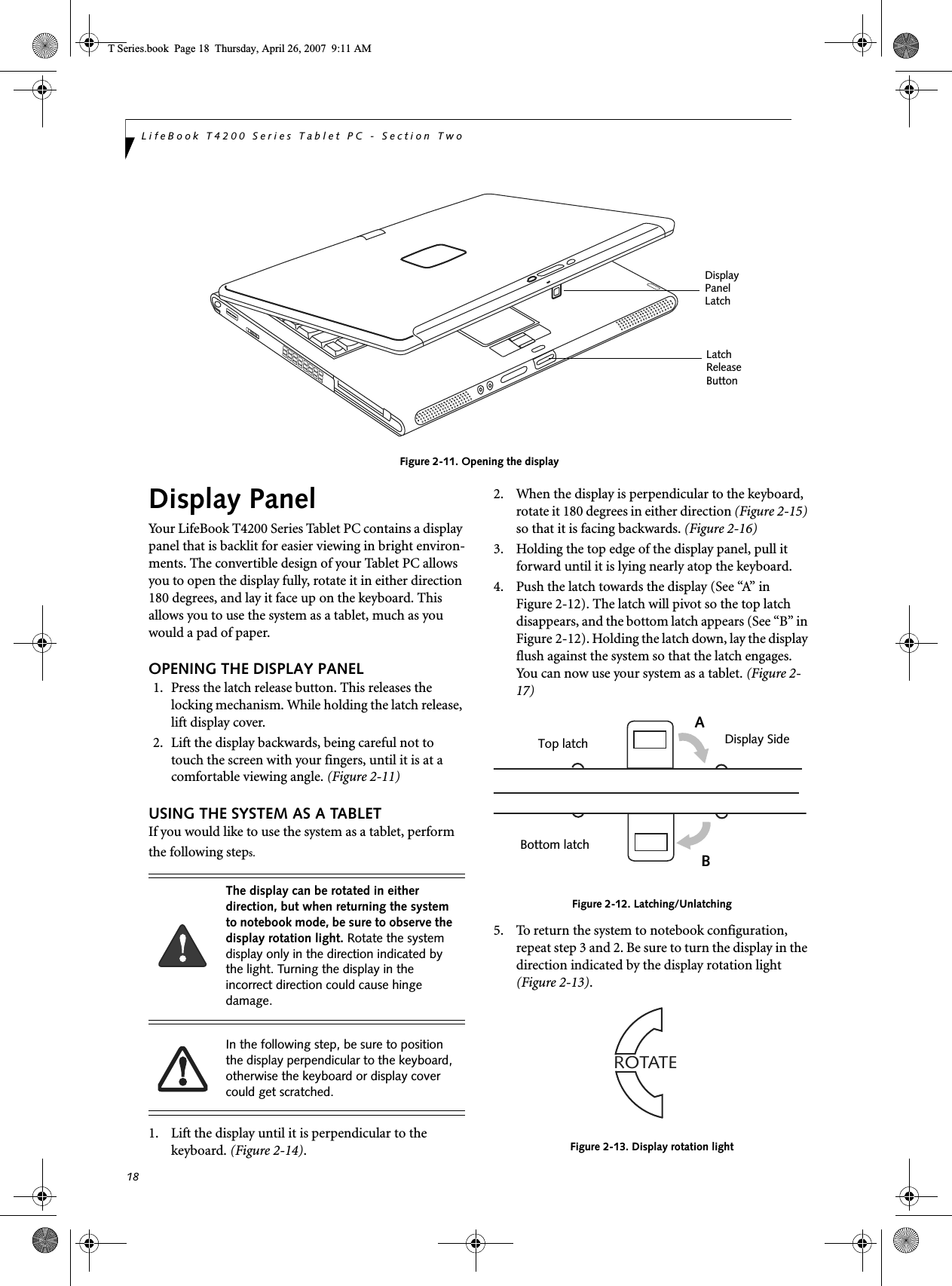
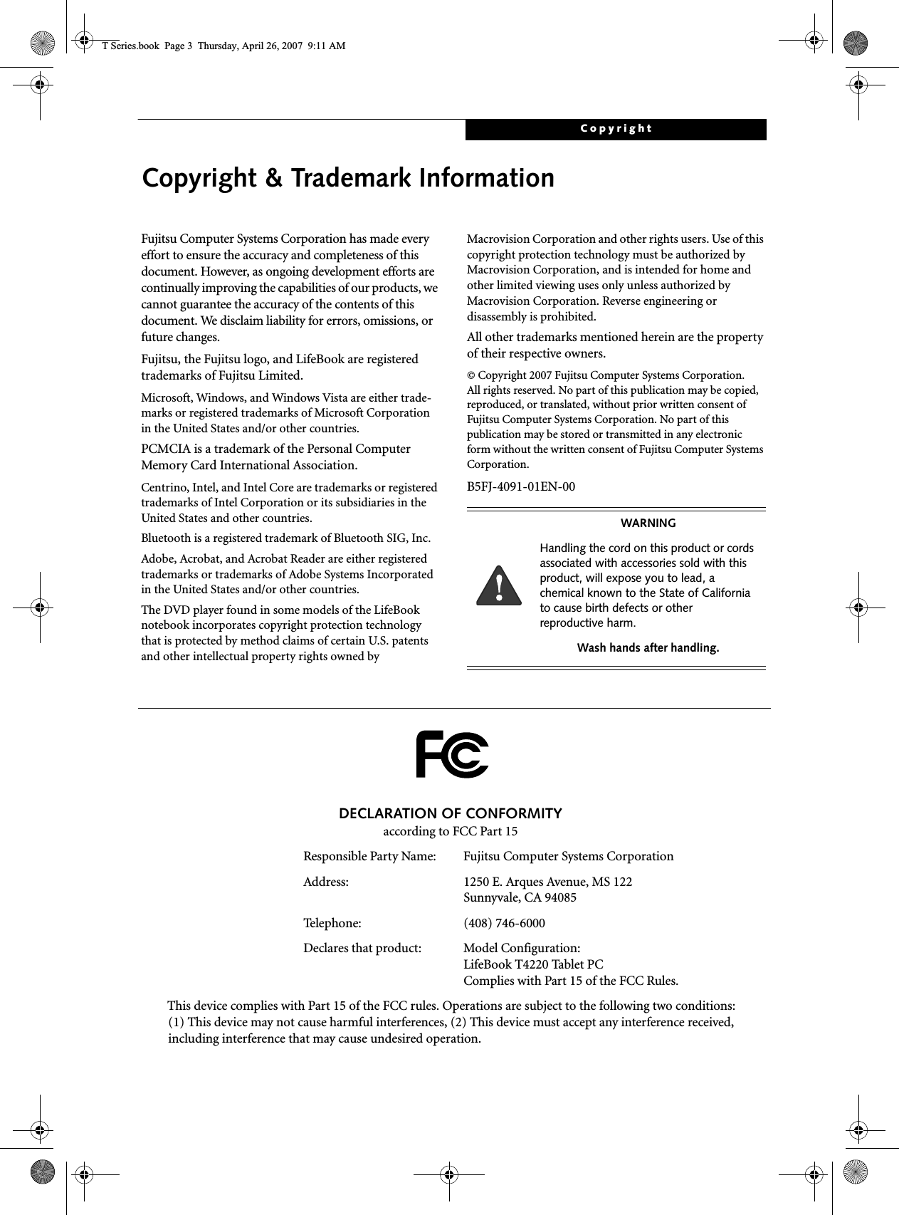
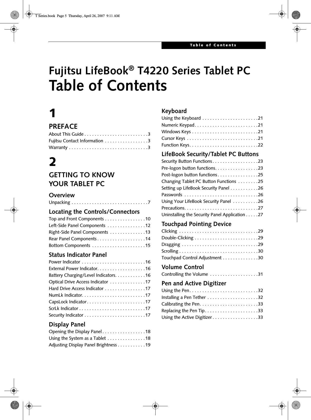
![19Getting to Know Your Tablet PCFigure 2-14. Fully open displayFigure 2-15. Rotating the displayFigure 2-16. Display rotated completelyFigure 2-17. System in tablet configurationADJUSTING DISPLAY PANEL BRIGHTNESSOnce you have turned on your Tablet PC, you may want to adjust the brightness level of the screen to a more comfortable viewing level. There are three ways to adjust the brightness, keyboard, power management utility, and Fujitsu Menu. Using Keyboard to Adjust BrightnessAdjusting the brightness using the keyboard changes the system setting (i.e., the settings you make via the func-tion keys automatically changes the brightness settings in the system’s Pen and Tablet Settings). ■[Fn+F6]: Pressing repeatedly will lower the brightness of your display.■[Fn+F7]: Pressing repeatedly will increase thebrightness of the display.Using Power Management to Adjust BrightnessTo adjust brightness with the power management utility, click Start -> Control Panel -> Tablet and Pen Settings (Windows XP) or Tablet PC Settings (Windows Vista). Select the Display tab and set the screen brightness slider for battery and AC power scenarios.Using the Fujitsu Menu to Adjust BrightnessTo adjust brightness using the Fujitsu menu, click on the Fujitsu Menu icon in the system tray in the lower right corner of the screen (or double-click the Function button). From the menu that appears, select Brightness Control. The Tablet and Pen Settings window will open. 90oDisplay rotation lightT Series.book Page 19 Thursday, April 26, 2007 9:11 AM](https://usermanual.wiki/Fujitsu-Client-Computing/WB0047/User-Guide-790092-Page-28.png)
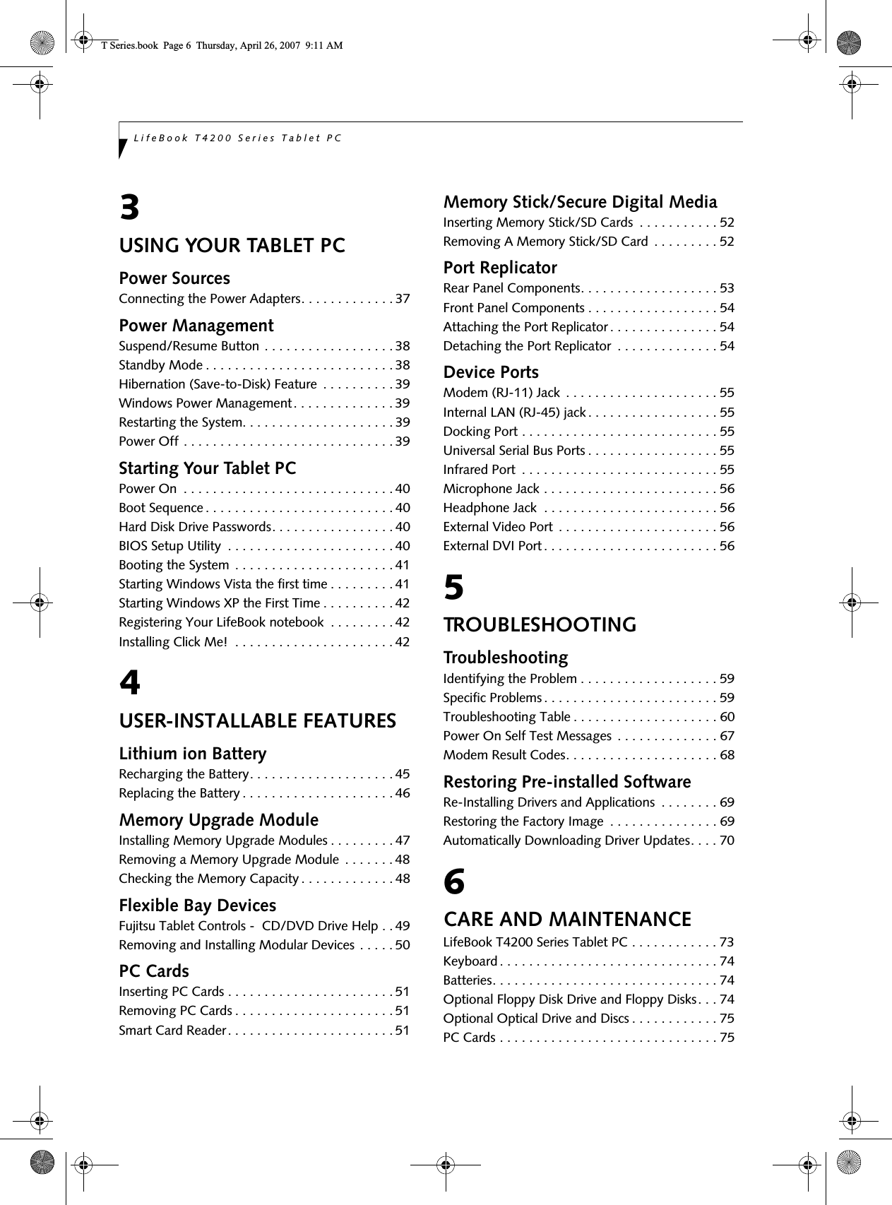
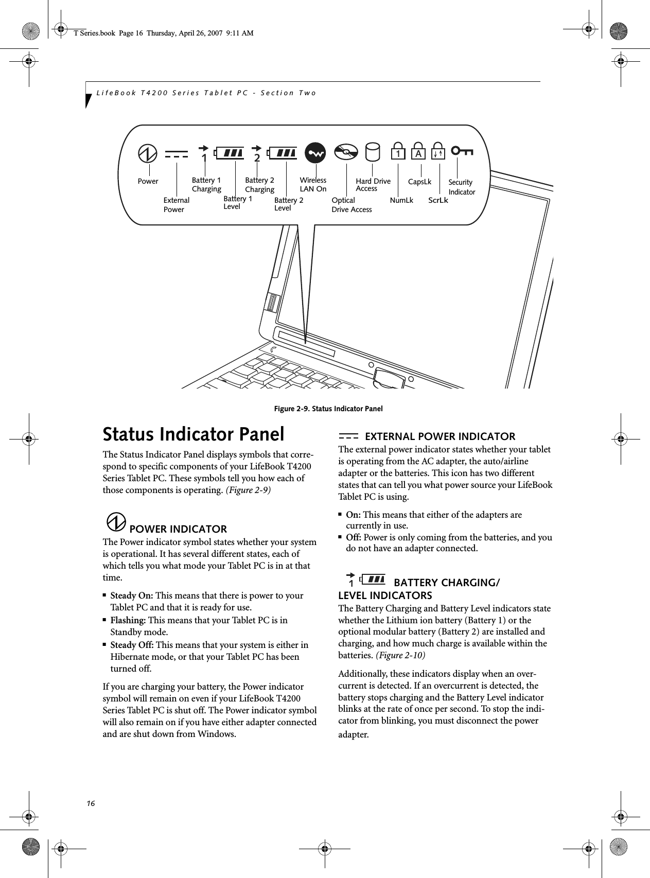
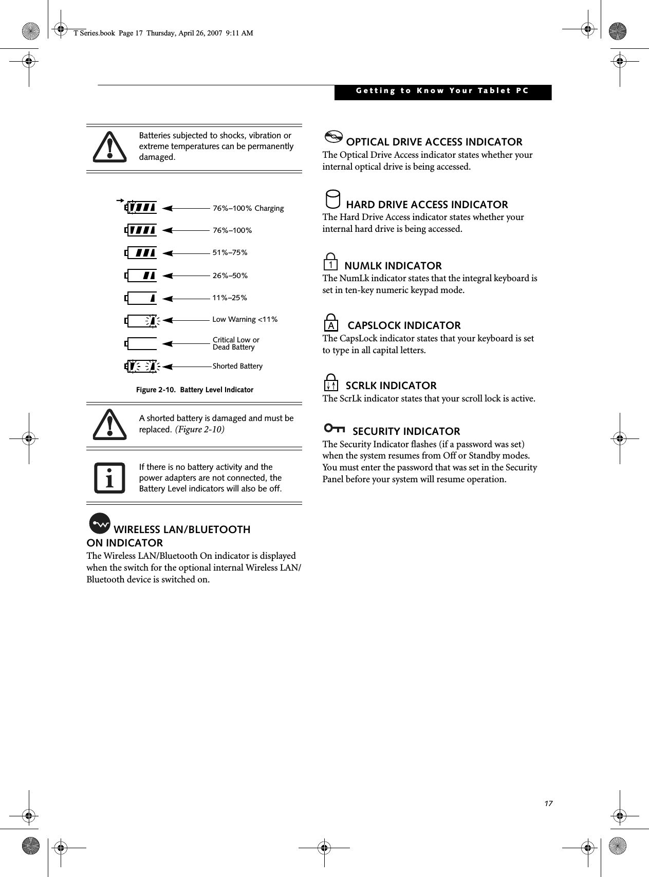
![21Getting to Know Your Tablet PCFigure 2-18. KeyboardKeyboardUSING THE KEYBOARDYour LifeBook T4200 Series Tablet PC has an integral 84-key keyboard. The keys perform all the standard functions of a 101-key keyboard, including the Windows keys and other special function keys. This section describes the following keys. (Figure 2-18)■Numeric keypad: Your Tablet PC allows certain keys to serve dual purposes, both as standard characters and as numeric and mathematical keys. The ability to toggle between the standard character and numerical keys is controlled through the [NumLk] key.■Cursor keys: Your keyboard contains four arrowkeys for moving the cursor or insertion point to the right, left, up, or down within windows, applications and documents. ■Function keys: The keys labeled [F1] through [F12], are used in conjunction with the [Fn] key to produce special actions that vary depending on what program is running. ■Windows keys: These keys work with your Windows operating system and function the same as the onscreen Start menu button, or the right button on your pointing device.NUMERIC KEYPADCertain keys on the keyboard perform dual functions as both standard character keys and numeric keypad keys. NumLk can be activated by pressing the [NumLk] key. Turning off the NumLk feature is done the same way. Once this feature is activated you can enter numerals 0 through 9, perform addition ( + ), subtraction ( - ),multiplication ( * ), or division ( / ), and enter decimal points ( . ) using the keys designated as ten-key function keys. The keys in the numeric keypad are marked on the front edge of the key to indicate their secondary func-tions. (Figure 2-18) WINDOWS KEYSYour LifeBook T4200 Series Tablet PC has two Windows keys: a Start key and an Application key. The Start key displays the Start menu. This button functions the same as your onscreen Start menu button. The Application key functions the same as your right mouse button and displays shortcut menus for the selected item. (Please refer to your Windows documentation for additional information regarding the Windows keys.) (Figure 2-18)CURSOR KEYSThe cursor keys are the four arrow keys on the keyboard which allow you to move the cursor up, down, left, and right in applications. In programs such as Windows Explorer, it moves the “focus” (selects the next item up, down, left, or right). (Figure 2-18)EndHomeFn Key Start KeyFunction KeysNumeric KeypadApplication Key Cursor Keys(outlined with thickblack line) T Series.book Page 21 Thursday, April 26, 2007 9:11 AM](https://usermanual.wiki/Fujitsu-Client-Computing/WB0047/User-Guide-790092-Page-30.png)
![22LifeBook T4200 Series Tablet PC - Section TwoFUNCTION KEYSYour Tablet PC has 12 function keys, F1 through F12. The functions assigned to these keys differ for each application. You should refer to your software documen-tation to find out how these keys are used. (Figure 2-18)[Fn] KeyThe [Fn] key provides extended functions for theTablet PC and is always used in conjunction with another key. ■[Fn+F3]: Pressing [F3] while holding [Fn] will toggle the Audio Mute on and off.■[Fn+F4]: Pressing [F4] while holding [Fn] will toggle the built-in pointing device on and off. ■[Fn +F5]: Pressing [F5] while holding [Fn] allows you to toggle between video compensation and no compensation. (Video compensation controls spacing on the display. When it is enabled, displays with lower pixel resolution will still cover the entire screen.)■[Fn+F6]: Pressing [F6] repeatedly while holding [Fn] will lower the brightness of your display. Note that adjusting the brightness using the keyboard changes the system setting.■[Fn+F7]: Pressing [F7] repeatedly while holding [Fn] will increase the brightness of the display.■[Fn+F8]: Pressing [F8] repeatedly while holding [Fn] will decrease the volume of your Tablet PC.■[Fn+F9]: Pressing [F9] repeatedly while holding [Fn] will increase the volume of your Tablet PC.■[Fn+F10]: Pressing [F10] while holding [Fn] allows you to change your selection of where to send your display video. Each time you press the combination of keys you will step to the next choice. The choices, in order, are: built-in display panel only, both built-in display panel and external monitor, or external moni-tor only.T Series.book Page 22 Thursday, April 26, 2007 9:11 AM](https://usermanual.wiki/Fujitsu-Client-Computing/WB0047/User-Guide-790092-Page-31.png)
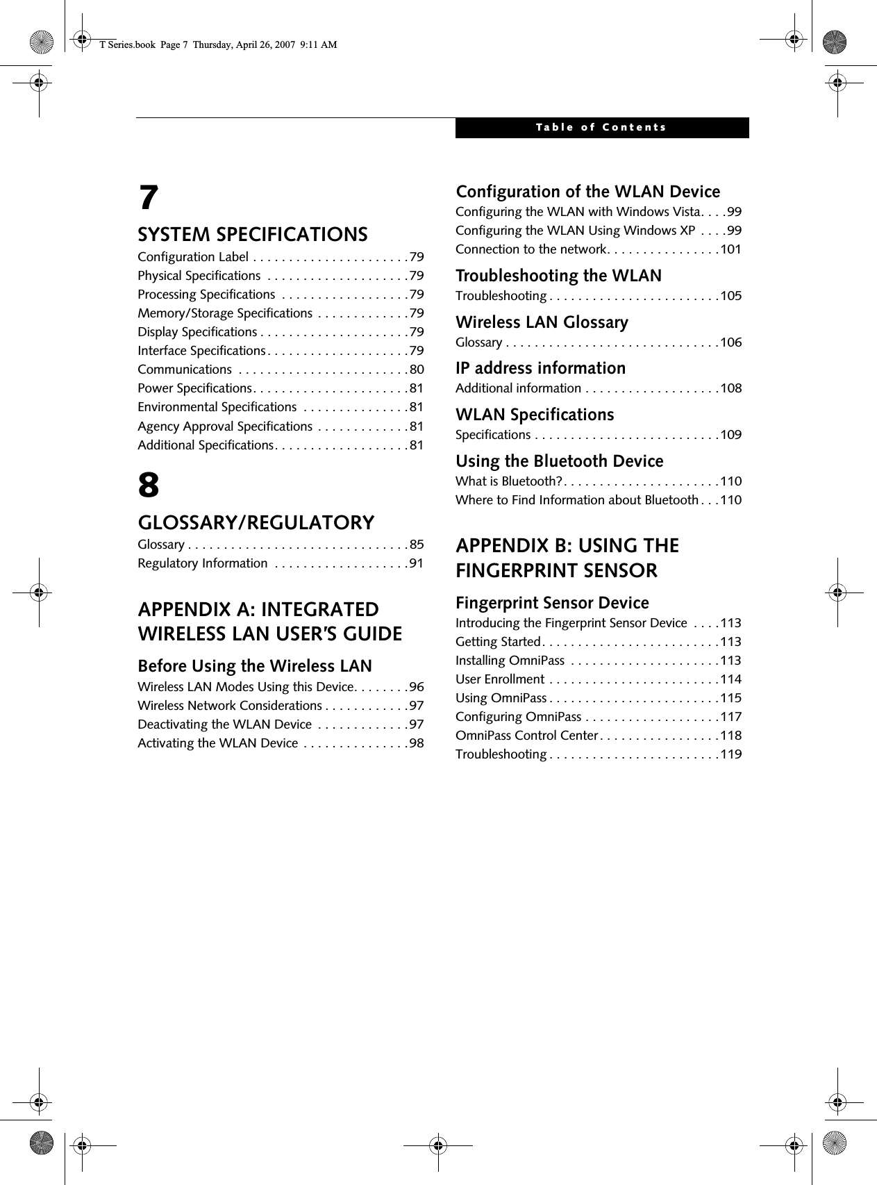
![23Getting to Know Your Tablet PCFigure 2-19. LifeBook T4200 Series Tablet PC Security/Tablet PC Buttons LifeBook Security/Tablet PC ButtonsA unique feature of your LifeBook T4200 Series Tablet PC is the array of Security and Tablet PC buttons. These buttons allow you to secure your Tablet PC from unau-thorized use and to launch specific applications and functions with the touch of a button. SECURITY BUTTON FUNCTIONSIf the security system is activated, upon starting your Tablet PC or resuming from Standby, Hibernate, or shut-down mode, the security system will require you to enter a password code using the security buttons. After you enter the correct password, your system will resume operation. The five security/Tablet PC buttons are located on the bottom right-hand side of the display when it is config-ured to be used as a notebook. All five buttons are used when implementing security functions. Four of the buttons are used to enter the pass-word, and the fifth is used as an Enter button. See Table 2-2 for information about each of the Security buttons.PRE-LOGON BUTTON FUNCTIONSAll five buttons can be used before logging on to Windows (i.e., the Windows logon screen is displayed). Three of the buttons have secondary functions. See Table 2-3 for information about each of the pre-logon functions.<Tab>/<Shift><Tab>When you press the Page Down button when the system is pre-logon, each press of the button will act as if you had pressed the [Tab] key.When you press the Fn button then press and release the Page Down button, each press of the button will act as if you had pressed the [Shift]+[Tab] key combination.<Enter>/<Escape>When you press the Page Up button when the system is pre-logon, each press of the button will act as if you had pressed the [Enter] key.Table 2-2. Security Panel Button FunctionsABn1234ENT(1) Application A Button (3) Button 3(2) Application B Button (4) Button 4Enter ButtonButton Icon System State Security Panel FunctionSystem is pre-boot or resuming from suspend Security Button 1Security Button 2Security Button 3Security Button 4Security Enter ButtonT Series.book Page 23 Thursday, April 26, 2007 9:11 AM](https://usermanual.wiki/Fujitsu-Client-Computing/WB0047/User-Guide-790092-Page-32.png)
![24LifeBook T4200 Series Tablet PC - Section TwoTable 2-3. Pre-logon Tablet PC Button FunctionsWhen you press the Fn button then press and release the Page Up button, each press of the button will act as if you had pressed the [Escape] key.Screen RotationThe screen rotation feature would normally be used when the system is configured as a tablet. When you would like to use the tablet as an eBook, for example, you would use the portrait orientation; when accessing spreadsheets or using the system as a notebook, you would more typically use landscape orientation.When the system is changed to tablet configuration, the orientation automatically changes to portrait mode by default. When you press the Screen Rotation button when the system is in pre-boot, the system screen orientation changes from portrait (vertical) to landscape (hori-zontal) or from landscape to portrait.Table 2-4. Post-logon Tablet PC Button FunctionsButton Icon System State Tablet PC Function Secondary Functions(Fn + Button)System is pre-logon (Windows logon screen is displayed) <Tab> <Shift><Tab><Enter> <Escape>Rotate screen NoneUsed to invoke secondary function NoneCtl+Alt+Del Button NoneThe screen orientation default can be changed by going to the Control Panel and double-clicking on the Fujitsu Tablet Controls icon and selecting the desired settings in the display properties. After changing the settings, save them in Fujitsu Tablet Controls.Button Icon System State Primary Tablet PC Function Secondary Functions(Fn + Button)System is post-logon (Windows desktop is displayed) Page Down User-defined Application A(Default = Calculator)Page Up User-Defined Application B(Default = MS Journal)Screen RotationDisplay Switching:1. LCD only2. CRT only3. Dual DisplaySecondary Function Selection Fujitsu Menu UtilityCtl+Alt+Del Button None T Series.book Page 24 Thursday, April 26, 2007 9:11 AM](https://usermanual.wiki/Fujitsu-Client-Computing/WB0047/User-Guide-790092-Page-33.png)
![25Getting to Know Your Tablet PCFunction / Fujitsu Menu Utility ButtonThe Function button works in conjunction with the other application buttons to provide additional func-tionality for the buttons. Refer to specific details above.POST-LOGON BUTTON FUNCTIONSAll five buttons can be used after logging on to Windows. Four of the buttons have secondary functions. See Table 2-4 for information about each of the post-logon functions.Page Down / Application A ButtonWhen you press the Page Down button when the system is running, each press of the button will scroll the screen down one frame. This allows you to navigate quickly through large documents.When you press the Fn button then press and release the Page Down/Application A button, you will automati-cally start whichever program is assigned to the button. The default application for this button is Calculator. See “Changing Tablet PC Button Functions” on page 25 to select a different application for this button.Page Up / Application B ButtonWhen you press the Page Up button when the system is running, each press of the button will scroll the screen up one frame. This allows you to navigate quickly through large documents.When you press the Fn button then press and release the Page Up/Application B button, you will automatically start whichever program is assigned to the button. The default application for this button is Microsoft Journal. See “Changing Tablet PC Button Functions” on page 25 to select a different application for this button.Screen Rotation /Display Switching ButtonThe screen rotation feature would normally be used only when the system is configured as a tablet. When you would like to use the tablet as an eBook, for example, you would use the portrait orientation; when accessing spreadsheets or using the system as a note-book, you would more typically use landscape orienta-tion.When the system is changed to tablet configuration, the orientation automatically changes to portrait mode by default. When you press the Screen Rotation /Display Switching button, the system screen orientation changes from portrait (vertical) to landscape (horizontal) or from landscape to portrait. Pressing the Fn button with while pressing the Screen Rotation button will switch the display output in the following order: LCD only, CRT only, dual display.Function / Fujitsu Menu Utility ButtonThe Function button works in conjunction with the other application buttons to provide additional func-tionality for the buttons. Refer to specific details above.Pressing the Fn button twice in succession causes the Fujitsu Menu Utility to appear on your screen, allowing you to modify certain system settings.Ctl+Alt+Del ButtonPressing and holding the Ctl-Alt-Del button for up to 750 milliseconds launches the Logon screen or the Windows Task Manager (if the system hasn’t yet been configured).CHANGING TABLET PC BUTTON FUNCTIONSThe Application A and B buttons can be changed to launch a program or perform an action you select. By default, the Application A button launches the Calcu-lator, and the Application B button launches MS Journal.To launch different applications or cause the Applica-tion A or B buttons to perform a specific action:1. Double-click on the Tablet and Pen Settings icon in the Control Panel. 2. Select the Tablet Buttons tab and select the button you would like to change from the list.3. Click [Change] and open the drop down list in the Action: field.4. Select the action you would like the button to perform. If you want to launch a program, click on Launch an Application then browse to the location of the program.5. Click [OK], then click [OK] again. The buttons will now perform the actions you have assigned to them.The screen orientation default can be changed by going to the Control Panel and double-clicking on the Fujitsu Tablet Controls icon and selecting the desired settings in the display properties. After changing the settings, save them in Fujitsu Tablet Controls.T Series.book Page 25 Thursday, April 26, 2007 9:11 AM](https://usermanual.wiki/Fujitsu-Client-Computing/WB0047/User-Guide-790092-Page-34.png)
![26LifeBook T4200 Series Tablet PC - Section TwoSETTING UP LIFEBOOK SECURITY PANELWhen you receive your Tablet PC, the security panel application is pre-installed without any passwords. The following sections provide detailed information on your security panel, how to set, change or remove passwords.Numbered ButtonsUse these buttons to enter your password.Enter ButtonAfter entering the button strokes, push this button to enter the password into the Tablet PC. PASSWORDSThe user and supervisor password may be set on this Tablet PC. A supervisor password is typically the same for all tablets and notebooks in a work group, office, or company to allow for system management. Individual computers in a group environment should not use a common password. A password consists of one to five button strokes plus the enter button. A valid stroke consists of pushing one or up to four buttons simulta-neously. The following are valid button strokes: ■Pushing [4] by itself■Pushing [2] and [3] at the same time■Pushing [1], [2], and [4] at the same time■Pushing [1], [2], [3], and [4] at the same timeThe following are valid passwords. The numbers within braces ({ }) are button strokes using more than one button. ■{[2]+[3]}, [1], [Enter]■[4], [enter]■{[1]+[3]}, {[2]+[3]+[4]}, [1], [4], [2], [Enter]Setting PasswordsWhen shipped from the factory, no passwords are set. You have a choice of having no password or setting a supervisor and user password. You must set the super-visor password before the user password. Setting Supervisor PasswordYou must have set a supervisor password before setting any user passwords. The supervisor password can bypass the user password.1. Go to the Start menu.2. Click on Run.3. Type in: C:\Program Files\Fujitsu\Security Panel Application\Supervisor\ FJSECS.EXE, then press [Enter]4. Follow the on-screen instructions to set the Super-visor password.Setting User Password1 Go to the Start menu.2. Click on All Programs.3. Click on Security Panel Application -> Security Panel Application.4. Follow the on-screen instructions to set the user password.USING YOUR LIFEBOOK SECURITY PANELThe security lock feature is in effect both when the system resumes from Off, Standby, or Hibernation state. You always need to push the Security Panel buttons to input the user password. Your system will not begin the boot sequence until you enter your supervisor/user password.From Off State1. Turn on your system.2. When the Security Indicator flashes, enter the pass-word and press Enter button (e.g., if the password is 22222, first press Button 2 five times, then press the Enter button). The Tablet PC will boot to normal operation.From Standby/Hibernation State1. Press your Suspend/Resume button.2. When the Security Indicator flashes, enter the pass-word and press Enter button.The Tablet PC should resume normal operation.Incorrect Password EntryIf an invalid supervisor or user password is entered three times in succession, the system will “beep” for about one minute. If a valid password is entered within a minute (while system beeps), the beeping will stop and the Tablet PC will resume normal operation. If no password is entered or an invalid password is entered while the system beeps, the system will return to its previous locked state (standby or off) and the Security Indicator will go off. To reactivate the Tablet PC after a password failure, you must press the Suspend/Resume button, then enter a correct password.• The purpose of supervisor password is to be able to bypass the user password in case the user password is forgotten. The supervisor password alone will not lock the system.• You must set the supervisor and user passwords for the security panel to work.You may change or remove the supervisor or user password by repeating the steps defined above.T Series.book Page 26 Thursday, April 26, 2007 9:11 AM](https://usermanual.wiki/Fujitsu-Client-Computing/WB0047/User-Guide-790092-Page-35.png)
![27Getting to Know Your Tablet PCPRECAUTIONSOpening and Closing the CoverBy default, closing the cover automatically places your system into Standby mode. Windows XP systems:You can change the action the system takes when the cover is closed by opening the Power Options Properties icon in the Control Panel, and selecting the Advanced tab. Make a choice from the drop down menu for “When I close the lid of my portable computer:” and click the [OK] button.) Opening the cover does not automatically place the Tablet PC into normal opera-tion. Instead, you must enter the proper security pass-word after pushing the Suspend/Resume button.Windows Vista systems:To change the default for Windows Vista systems when the cover is closed:1. Open the system Control Panel.2. If the display is in Category view, click "Change battery settings" under the "Mobile PC" category. If it is in Classic view, click "Power Options".3. Click "Choose what closing the lid does" in the left pane.4. Select the desired action for "When I close the lid".Low Battery OperationsIf your Tablet PC has a low battery, pushing the suspend/resume button only turns on the Security Indi-cator. Your Tablet PC does not unlock, the Security Indi-cator turns off after one minute. To resume normal operation, first attach a power supply to the Tablet PC. Then you may unlock the Tablet PC.UNINSTALLING THE SECURITY PANEL APPLICATIONYou have two options when uninstalling the security panel application:■Remove passwords and uninstall the security panel application software. This will disable all security features.■Uninstall the security panel application with password still active. This will not allow any changes to the pass-word. Uninstalling the Security Panel Application SoftwareRemove passwords when User wants no password protection whatsoever and doesn’t want to give anybody the utility to set a password on their computer. In this case, if passwords (supervisor, user, or both) are set, the passwords must first be cleared BEFORE removing the application. To clear passwords, follow same procedure in SETTING PASSWORD CODES except this time, select REMOVE, enter current password then click Next. When asked to confirm select Ye s .Removing Security Panel Application with Passwords Still ActiveUsing this feature will not allow any changes to the pass-word. User: 1. Go to Start -> Control Panel.2. Open Add or Remove Programs Properties in the Control Panel. 3. Select the Security Panel Application in the list, and click Change/Remove. 4. When Confirm File Deletion box appears, click Ye s .Supervisor:1. Go to Start -> Control Panel.2. Open Add or Remove Programs Properties in the Control Panel. 3. Select the Security Panel Application for Supervisor in the list, and click Change/Remove. 4. When Confirm File Deletion box appears, click Ye s .Reinstalling the Security Panel ApplicationTo reinstall supervisor or user security application, you will need your Drivers and Applications CD. The Utili-ties\Security Panel Application folder contains two separate folders: Supervisor and User. The setup files for supervisor and user security applications are contained in those folders. 1. Go to the Utilities\Security Panel Application\ Supervisor folder on the CD and double-click the setup.exe file. The Installing Security Panel Applica-tion window will appear. Follow the instructions on the screen.2. Go to the Utilities\Security Panel Application\User folder on the CD and double-click the setup.exe file. The Installing Security Panel Application window will appear. Follow the instructions on the screen.Remember the user password you specified on the Security Panel Application. If you forget the password you will not be able to use your computer. The supervisor pass-word can override the user password.Removing the applications does not remove the password. It simply removes the ability to change/add/remove passwords. To change your password you must reinstall the application.T Series.book Page 27 Thursday, April 26, 2007 9:11 AM](https://usermanual.wiki/Fujitsu-Client-Computing/WB0047/User-Guide-790092-Page-36.png)
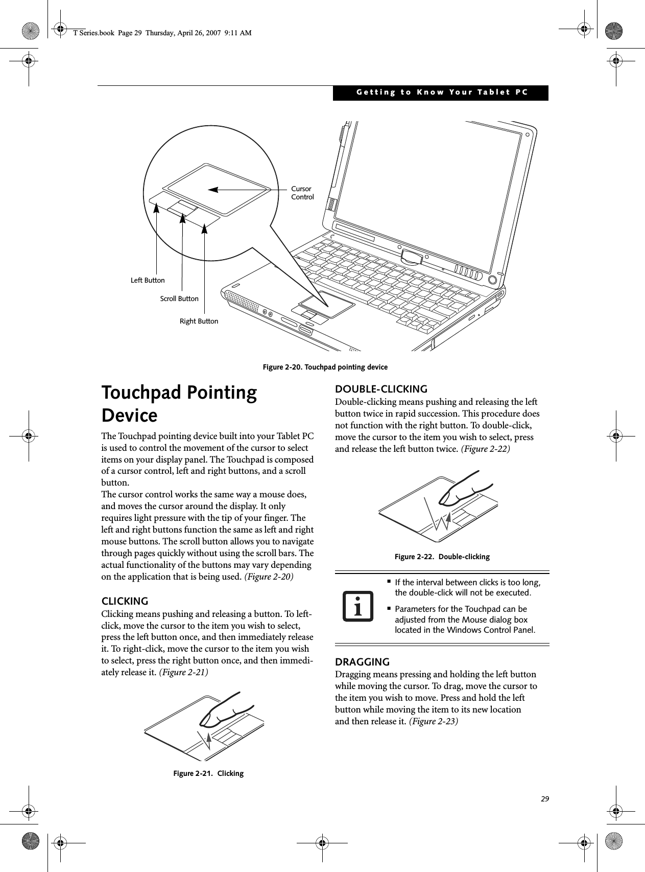
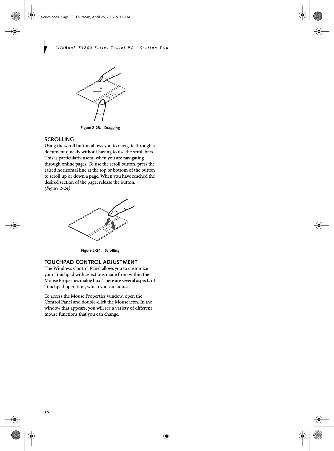
![31Getting to Know Your Tablet PCVolume ControlYour Fujitsu Tablet PC has multiple volume controls which interact with each other. CONTROLLING THE VOLUMEThe volume can be controlled in several different ways:■Volume can be set from within the Volume Control on the Taskbar.■Volume can be controlled with the [F8] and [F9] func-tions keys. Pressing [F8] repeatedly while holding [Fn] will decrease the volume of your Tablet PC. Pressing [F9] repeatedly while holding [Fn] will increase the volume of your Tablet PC.■Volume can be controlled by many volume controls that are set within individual applications.■Certain external audio devices you might connect to your system may have hardware volume controls.■Each source discussed above puts an upper limit on the volume level that must then be followed by the other sources. We recommend that you experiment with the various volume controls to discover the optimal sound level.Any software that contains audio files will also contain a volume control of its own. If you install an external audio device that has an independent volume control, the hardware volume control and the software volume control will interact with each other. It should be noted that if you set your software volume to Off, you will override the external volume control setting. T Series.book Page 31 Thursday, April 26, 2007 9:11 AM](https://usermanual.wiki/Fujitsu-Client-Computing/WB0047/User-Guide-790092-Page-40.png)
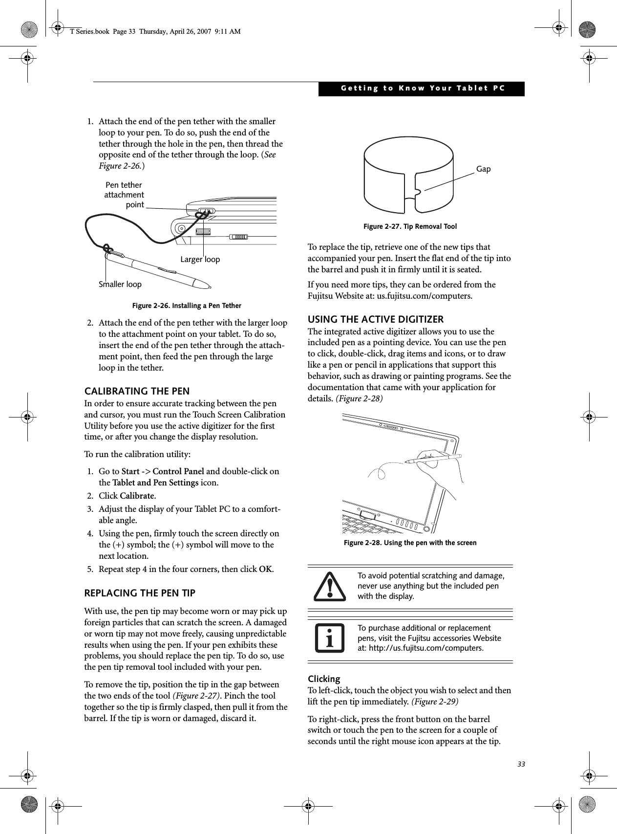
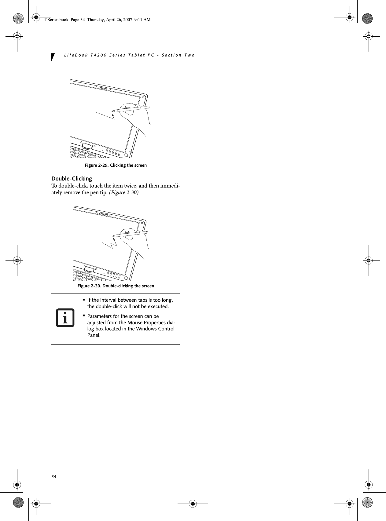
![32LifeBook T4200 Series Tablet PC - Section TwoPen and Active DigitizerUSING THE PENYou can use the LifeBook T4200 Series Tablet PC pen to generate and create electronic “ink”, to select items, and to navigate through programs on the Tablet PC. Programs that support handwriting recognition also allow you to write characters directly on the screen with the pen. You can also use the pen as a drawing tool.Figure 2-25. LifeBook T4200 Series PenThe screen reacts when the pen tip is approximately 1/8 inch (3-5 mm) from the screen. The pen has four switches: a tip switch, a barrel button toggle switch with switches at both ends, and an "eraser" switch, located on the end of the barrel. By default, the tip switch corre-sponds to the left mouse button, and the front toggle (closest to the pen tip) barrel button switch corresponds to the right mouse button (when used in combination with the tip switch). The rear toggle of the barrel button switch and the eraser switch at the end of the barrel act as electronic ink “erasers”.The rear toggle, eraser, and tip click pressures can be changed by clicking [Start] -> Control Panel, and double-clicking the Fujitsu Pen Settings icon. Note that the rear toggle switch and the eraser switch are both affected by the same settings; they cannot be changed individually. To change the rear toggle and eraser button function, select the drop-down list to select a new function, then click [Apply]. If you don’t want the rear toggle and button switch to have any function, select Ignore from the list. Adjusting the click pressure determines how much pres-sure must be put on the pen tip in order for the screen to react. The softer it is set, less pressure is required; the harder it is set, more pressure is required. To change the click pressure, use the slider bar to make the click pres-sure harder or softer, then click [Apply]. Here are some hints that may help you use the pen more effectively:• To activate the tip switch, tap or hold the pen tip against the screen.• To activate the barrel button switch, press and hold the end of the button you wish to use (front toggle is the right mouse button switch; the rear toggle and eraser button both act as electronic “erasers”).• To move the cursor, hold the pen tip within 1/8 inch (3 - 5 mm) from the screen and move the pen.• To start a program, double-tap the pen tip (tap the pen tip twice rapidly) on the program icon as you would double-click a mouse.•To select an object, tap the pen tip on the object once. •To double-click an object, quickly tap the object twice.INSTALLING A PEN TETHERTo prevent dropping or losing your pen, you should attach it to your system using the pen tether that is included with the system. To attach the pen tether to your Tablet PC, perform the following steps:You are advised to use a screen protector on your system display to minimize the chance of its being scratched. Screen protectors are available from the Fujitsu Website at us.fujitsu.com/computers. The LifeBook T4200 Series Tablet PC pen is a high-quality electronic instrument that can be damaged if used improperly. Treat the pen as you would any precision device. Observe the following guidelines:• Do not tap the pen on surfaces other than the Tablet PC screen.• Do not try to turn the thumb grip on the pen; it is designed for inserting and removing the pen from the pen holder.• Never store the pen with the tip bearing the weight of the pen (e.g., sitting tip down in a pencil cup). Storing the pen tip down could distort the internal mechanism over a period of time (especially in higher temperatures), causing the tip to act as if it is always depressed. The pen should be stored in the pen holder when not in use.Tip SwitchBarrel SwitchEraser ButtonUse only the pen provided with your Tablet PC. Do not use substitutes that were not designed for the LifeBook T4200 Series Tablet PC.T Series.book Page 32 Thursday, April 26, 2007 9:11 AM](https://usermanual.wiki/Fujitsu-Client-Computing/WB0047/User-Guide-790092-Page-41.png)

![40LifeBook T4200 Series Tablet PC - Section ThreeStarting Your Tablet PCPOWER ONThe Suspend/Resume button is used to turn on your LifeBook T4200 Series Tablet PC from its off state. Once you have connected your AC adapter or charged the internal Lithium ion battery, you can power on your Tablet PC. .Press the Suspend/Resume button to start your system.(See Figure 2-4 on page 10 for location). When you are done working you can either leave your Tablet PC in Standby mode, See “Standby Mode” on page 38, or you can turn it off. See “Power Off” on page 39.When you Power On your Tablet PC, it will perform a Power On Self Test (POST) to check the internal parts and configuration for correct functionality. If a fault is found, your Tablet PC will emit an audio warning and/or an error message will be displayed. See “Power On Self Test Messages” on page 67. Depending on the nature of the problem, you may be able to continue by starting the operating system or by entering the BIOS setup utility and revising the settings.After satisfactory completion of the Power On Self Test (POST), your Tablet PC will load your operating system.BOOT SEQUENCEThe procedure for starting-up your Tablet PC is termed the Bootup sequence and involves your Tablet PC’s BIOS. When your Tablet PC is first turned on, the main system memory is empty, and it needs to find instruc-tions to start up your Tablet PC. This information is in the BIOS program. Each time you power up or restart your Tablet PC, it goes through a boot sequence which displays a Fujitsu logo until your operating system is loaded. During booting, your Tablet PC is performing a standard boot sequence including a Power On Self Test (POST). When the boot sequence is completed without a failure and without a request for the BIOS Setup Utility, the system displays the operating system’s opening screen.The boot sequence is executed when:■You turn on the power to your Tablet PC.■You restart your Tablet PC from the WindowsShut Down dialog box.■The software initiates a system restart. Example:When you install a new application.HARD DISK DRIVE PASSWORDSTo provide additional security for your data, you can assign passwords to the hard disk drive(s). This feature is managed in the system BIOS Setup Utility. See BIOS Setup Utility below for information about accessing the utility.BIOS SETUP UTILITYThe BIOS Setup Utility is a program that sets up the operating environment for your Tablet PC. Your BIOSis set at the factory for normal operating conditions, therefore there is no need to set or change the BIOS’ environment to operate your Tablet PC.The BIOS Setup Utility configures:■Device control feature parameters, such as changingI/O addresses and boot devices.■System Data Security feature parameters, suchas passwords.Entering the BIOS Setup UtilityTo enter the BIOS Setup Utility do the following (or use the TrustedCore Menu, as detailed in the next section):1. Turn on or restart your LifeBook notebook.2. To enter the BIOS Setup Utility, press the [F2] key once the Fujitsu logo appears on the screen. This will open the main menu of the BIOS Setup Utility with the current settings displayed, or,3. Press the [RIGHT ARROW] or [LEFT ARROW] key to scroll through the other setup menus to review or alter the current settings.When you turn on your Tablet PC, be sure you have a power source. This means that a battery is installed and charged, or that the AC or Auto/Airline adapter is connected and has power.When the system display is closed, the Suspend/Resume button is disabled. This feature prevents the system from being accidentally powered up when not in use. Never turn off your Tablet PC during the Power On Self Test (POST) or it will cause an error message to be displayed when you turn your Tablet PC on the next time. See “Power On Self Test Messages” on page 67Remember your passwords. If you set and forget your User and Master hard disk passwords, Fujitsu Computer Systems will not be able to reset it. You may lose data and have to replace your system board or hard disk drive.T Series.book Page 40 Thursday, April 26, 2007 9:11 AM](https://usermanual.wiki/Fujitsu-Client-Computing/WB0047/User-Guide-790092-Page-49.png)
![41Using Your Tablet PCUsing the TrustedCore MenuWhen the Fujitsu logo appears on the screen. press the [Enter] key or click on the left mouse or touchpad button; the TrustedCore Menu will appear. The TrustedCore Menu provides shortcuts to the following menus and information screens: ■BIOS Setup■Diagnostic Screen■Boot Menu■Patent Information■System Information■Continue BootingClicking on any of the fields will invoke the screen, information, or action described.The Boot Menu can also be invoked by pressing the [F12] key when the Fujitsu logo appears on the screen.BIOS GuideA guide to your Tablet PC’s BIOS is available online. Please visit our service and support Website at http://www.computers.us.fujitsu.com/support. Once there, select Support, then select Tablet PCs under User’s Guides. Select LifeBook Tablet PC BIOS Guides from the pull-down menu for your Tablet PC series. If you are unsure of your Tablet PC’s BIOS number, refer to your packing slip.BOOTING THE SYSTEMWe strongly recommend that you not attach any external devices and do not put a DVD/CD in your drive until you have gone through the initial power on sequence.When you turn on your LifeBook notebook for the first time, it will display a Fujitsu logo on the screen. If you do nothing the system will load the operating system, and then the Windows Welcome will begin.Depending upon your operating system (Windows Vista or XP edition), there is a different procedure for stating your system for the first time, as outlined below.STARTING WINDOWS VISTA THE FIRST TIMEIn order to ensure that you receive the most benefits from the Windows Vista operating system, it should be registered the first time you use it. 1. First of all, you will need to read and accept the End User License Agreements (EULAs). 2. You will be prompted to enter your User Name and Password and you will be given a chance to select an icon for your account.3. The next screen asks for a Computer Name and allows you to choose a desktop background. 4. You will next see a "Help protect Windows automat-ically" screen in which the default choice is "Use recommended settings”. The other two choices are "Install important updates only" and "Ask me later". Select from the three choices.5. On the next screen set your time and date settings. 6. You will next see the "Select your computer's current location" screen. Make your selection from Home, Work (Default), and Public location. 7. The "Thank you" screen follows and an offer for free Norton is extended. Following are several screens while Windows checks the system performance.8. Windows will then boot up for the first time.Registering Windows Vista with Microsoft1. After Windows has booted up for the first time, the Control Panel Welcome Center will appear. If the Register Windows Online icon is not seen in the window, click on “Show all 14 items”.If your data security settings require it, you may be asked for a password before the BIOS main menu will appear.The first time you initialize your Windows Vista system, the screen will be blank for approximately two minutes. This is normal. After initialization, a “Set Up Windows” dialog box will appear.Important: During the setup procedure, do not disconnect the power supply, press any buttons, or use any peripheral devices such as a mouse, keyboard, or remote control.■If you reject the terms of the license agreement you will be asked to review the license agreement for information on returning Windows or to shut down your LifeBook notebook.■You cannot use your notebook until you have accepted the License Agreement. If you stop the process your notebook will return to the beginning of the Windows Welcome Process, even if you shut your notebook down and start it up again.T Series.book Page 41 Thursday, April 26, 2007 9:11 AM](https://usermanual.wiki/Fujitsu-Client-Computing/WB0047/User-Guide-790092-Page-50.png)
![42LifeBook T4200 Series Tablet PC - Section Three2. Click on Register Windows Online and follow the instructions that appear to register your copy of Windows.STARTING WINDOWS XP THE FIRST TIMERegistering Windows XP with MicrosoftIn order to ensure that you receive the most benefits from the Windows operating system, it should be registered the first time you use it. After you receive the Windows Welcome screen, you will be prompted to enter registration information in the following order.First of all, you will need to read and accept the End User License Agreements (EULAs). After accepting the EULAs, you will be asked if you want to enable the Auto-matic Updates feature. Acceptance of this feature is recommended because it allows your system to be updated automatically whenever an important change becomes available for your notebook.Several additional windows will appear, prompting you to enter a name and description for your computer, an Administrator password, and a domain name. Read the instructions on the screens carefully and fill in the infor-mation as directed. You will then be automatically connected to the Internet, if you have an appropriate connection available. If an automatic connection is not possible, you will be asked about how you dial out from where you will be using your LifeBook notebook. If you are not connected to a phone line and plan to register at a later time, you may click the Skip button.Once you are connected to the Internet, you will be asked if you wish to continue with the registration. If you select Ye s you will then enter your name and address, and email address if desired. Click Next to complete registration.REGISTERING YOUR LIFEBOOK NOTEBOOKHow do I register my LifeBook notebook?You can register your LifeBook by going to our website:us.fujitsu.com/computersYou will need to be set up with an Internet Service Provider (ISP) to register online. INSTALLING CLICK ME! Windows Vista SystemsThe first time you boot up your system, you will see a “Primary Settings for the PC” window. This window explains the installations which will be performed by the Click Me! utility. If you click [Execute], Click Me! will begin installing. If after clicking the button you receive a “User Account Control” window, you will be asked for your permission to continue. Click [Yes] to continue. If you cancel the operation, the Click Me! icon will appear on your desktop for later installation. Windows XP SystemsThe first time you boot up your system, you will see an icon called Click Me! in the Start menu. We highly recommend that you install the ClickMe! utility the first time you boot up. When you click the Click Me! icon, your system will automatically build the icon tray in the bottom right of the screen. These icons provide links to utilities that you will frequently access., such as wireless LAN software provided by the wireless LAN manufac-turer. FUJITSU DRIVER UPDATE UTILITY Your system has a convenient tool called the Fujitsu Driver Update (FDU) utility. With FDU, you can choose to automatically or manually go to the Fujitsu site to check for new updates for your system. For more infor-mation about the FDU utility, refer to “Automatically Downloading Driver Updates” on page 83.■If you reject the terms of the license agreement you will be asked to review the license agreement for information on returning Windows or to shut down your LifeBook notebook.■You cannot use your LifeBook notebook until you have accepted the License Agreement. If you stop the process your notebook will return to the beginning of the Windows Welcome Process, even if you shut your notebook down and start it up again.Before installing the ClickMe! utility, be sure the wireless LAN switch is turned on.There may be additional third-party applications that are not installed by the ClickMe! utility. For more information, refer to your Getting Started Guide.ClickMe!T Series.book Page 42 Thursday, April 26, 2007 9:11 AM](https://usermanual.wiki/Fujitsu-Client-Computing/WB0047/User-Guide-790092-Page-51.png)

![48LifeBook T4200 Series Tablet PC - Section FourREMOVING A MEMORY UPGRADE MODULE1. Perform steps 1 through 4 of Installing a Memory Upgrade Module.2. Pull the clips sideways away from each side of the memory upgrade module at the same time. 3. While holding the clips out, remove the module from the slot by lifting it up and pulling towards the rear of your tablet. (Figure 4-5)Figure 4-5. Removing a Memory Upgrade Module4. Store the memory upgrade module in a static guarded sleeve.5. Replace the cover. (Figure 4-4)6. Replace the screws.CHECKING THE MEMORY CAPACITYOnce you have changed the system memory capacity by either adding or removing a memory upgrade module, be sure to check that your tablet has recognized the change.You can check the memory capacity by clicking [Start]-> Control Panel, then double-clicking the System icon. Select the General tab and check the amount of memory under “Computer.”The amount of memory displayed should be approxi-mately the total of all memory modules installed. There may be a discrepancy of 8 MB which is allocated for fixed video memory.The memory upgrade module is not something you routinely remove from your tablet. Once it is installed, you should leave it in place unless you want to change system memory capacity.Your Tablet PC uses Dynamic Video Memory Technology (DVMT), which allows the video driver to dynamically determine the amount of memory that is used. Your system can use the following maximums for video functions:Windows XP: 128 MBWindows Vista: 64 MB (with 512 MB system memory); 256 MB (with 1 GB system memory); 384 MB 9 with 1.5 GB or more system memory). If the total memory displayed is incorrect, check that your memory upgrade module is properly installed. (If the module is properly installed and the capacity is still not correctly recognized, see Troubleshooting on page 60.T Series.book Page 48 Thursday, April 26, 2007 9:11 AM](https://usermanual.wiki/Fujitsu-Client-Computing/WB0047/User-Guide-790092-Page-57.png)
![49User-Installable FeaturesFigure 4-6 Flexible BayFlexible Bay DevicesYour Fujitsu Tablet PC contains a Flexible Bay. The Flex-ible Bay can house an optical drive, a Lithium ion battery, or a weight saver. (Figure 4-6)Your Flexible Bay will have one of the following devices installed. ■Modular Dual-Layer Multi-Format DVD Writer: This allows you to access movies, software, and audio DVD/CDs and record to DVD, CD, and DVD-RAM discs.■Modular DVD/CD-RW combo drive: This allows you to access movies, software, and audio DVD/CDs as well as to write to CDs. ■Modular Lithium ion battery: This is a rechargeablebattery that can be used to power your Tablet PC when an adapter is not connected.■Weight Saver: This is used to fill the bay when no device is needed.FUJITSU TABLET CONTROLS - CD/DVD DRIVE HELP The CD/DVD Drive tab of the Fujitsu Tablet Controls utility allows you to enable or disable your DVD drive when the Tablet PC is used in “undocked” (i.e., not connected to a port replicator) tablet mode.Using the Optical Drive Disabling FeatureThe CD/DVD tab of the Fujitsu Tablet Controls window consists of three checkboxes:■Lock CD/DVD drive when the unit is in tablet mode ■Show tray icon when CD/DVD drive is locked. ■Show notification messages when CD/DVD drive is locked/unlocked Lock CD/DVD drive when the unit is in tablet mode:This checkbox should normally be checked (see “Impor-tant Notes” above). If you would like to access the DVD drive while your system is in undocked tablet mode, deselect this checkbox. A message will appear asking if you really want to unlock the drive. Click [OK] to keep the checkbox checked, or [Cancel] to uncheck it and return to the utility.Show tray icon when CD/DVD drive is locked:This checkbox should normally be checked. If you would not like the Fujitsu Tablet Controls icon to appear in the system tray when the drive is locked, clear this box.Show notification messages when CD/DVD drive is locked/unlocked:This checkbox should normally be checked. If you would not like to be prompted when the drive is locked or unlocked, clear this box.Buttons■Click the [OK] button to accept the changes and close the window. ■Click the [Apply] button to accept the changes and leave the window open. ■Click the [Cancel] button to close the window without accepting the change. ■Click the [Help] button to view the help file associated with the selected tab within Fujitsu Tablet Controls. Flexible BayFlexible Bay Eject LeverThe DVD drive in your Tablet PC is designed to work optimally when the system is lying flat on a stable surface. Using the drive while the system is not on a flat surface could result in damage to the drive and/or the media. SUCH DAMAGE IS NOT COVERED UNDER YOUR WARRANTY. You are strongly advised not to use the drive while the system is in undocked tablet mode. This feature is in effect only when the user is logged-in.T Series.book Page 49 Thursday, April 26, 2007 9:11 AM](https://usermanual.wiki/Fujitsu-Client-Computing/WB0047/User-Guide-790092-Page-58.png)
![50LifeBook T4200 Series Tablet PC - Section FourSystem Tray IconWhen your system is in undocked tablet mode, and the “Lock CD/DVD drive when the unit is in tablet mode” box is checked, a Fujitsu Tablet Controls icon will appear at the bottom right of the display. When you select this icon, a menu will appear containing three items:■Unlock CD/DVD Drive for this tablet session ■Configure ■About Unlock CD/DVD Drive for this tablet sessionWhen you click this menu item, you will be asked whether you really want to unlock the drive. To unlock the drive, click [Yes]. Note that enabling the drive in this manner will not change the setting in the Fujitsu Tablet Controls control panel applet.ConfigureWhen you click this menu item, the Fujitsu Tablet Controls window appears.AboutWhen you click About, the help file will open.REMOVING AND INSTALLING MODULAR DEVICES There are two ways to remove and install modular devices in the Flexible Bay:■Cold-swapping: swapping devices while your Tablet PC is powered off.■Hot-swapping: swapping devices while your system is active using the Safely Remove Hardware icon from your taskbar.Cold-swappingTo cold-swap modular devices in your Flexible Bay follow these easy steps: (Figure 4-7)1. Close any open files.2. Shut down your Tablet PC.3. Pull out the Flexible Bay eject lever. This will push your device out slightly, allowing you to remove it.4. Slide your device out until it is clear of the bay.This will require light force. Figure 4-7 Removing/Installing a device in the Flexible Bay5. Slide the device you are installing into your tablet until it clicks into place.6. It is now safe to turn your tablet back on.7. You can now access and use the device.Your Tablet PC will automatically detect the new device and activate it within your system. The drive letters asso-ciated with the device will be created and listed under My Computer and Windows Explorer. Hot-swapping Hot-swapping is provided through the Safely Remove Hardware utility. The icon for the utility appears in the system tray. Click on the icon and follow the on-screen instructions.You should never leave your Flexible Bay empty when the tablet is in operation. If left empty, dust or foreign matter may accumulate inside the tablet.Use care when aligning or seating devices in the bay. If the fit is incorrect, you may damage the bay or device. If the device does not move easily in the bay, remove it and check for dirt or foreign objects. It will require a firm push to latch it in place.Flexible Bay Eject LeverT Series.book Page 50 Thursday, April 26, 2007 9:11 AM](https://usermanual.wiki/Fujitsu-Client-Computing/WB0047/User-Guide-790092-Page-59.png)
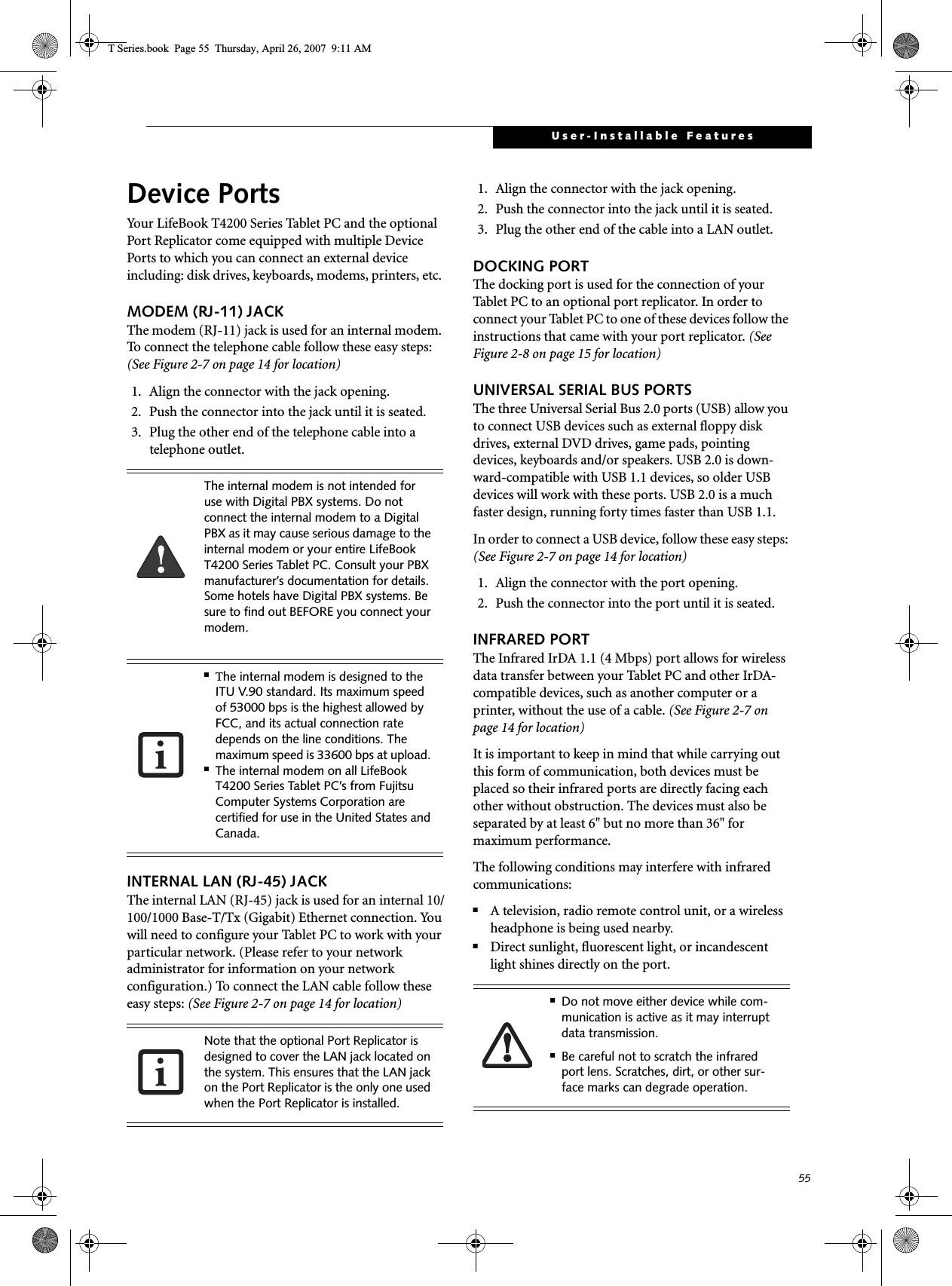
![56LifeBook T4200 Series Tablet PC - Section FourMICROPHONE JACKThe microphone jack allows you to connect an external mono microphone. Your microphone must be equipped with a 1/8”(3.5 mm) mono mini-plug in order to fit into the microphone jack of your Tablet PC. In order to connect a microphone follow these easy steps: (See Figure 2-4 on page 10 for location)1. Align the connector with the port opening.2. Push the connector into the port until it is seated.HEADPHONE JACKThe headphone jack allows you to connect headphones or powered external speakers to your Tablet PC. Your headphones or speakers must be equipped with a 1/8” (3.5 mm) stereo mini-plug. In order to connect head-phones or speakers follow these easy steps: (See Figure 2-4 on page 10 for location)1. Align the connector with the port opening.2. Push the connector into the port until it is seated.EXTERNAL VIDEO PORTThe external video port allows you to connect an external monitor or LCD projector. In order to connect an external monitor follow these easy steps: (See Figure 2-7 on page 14 for location). There is also an external VGA monitor on the port replicator (See Figure 4-11 on page 53 for location). 1. Remove the cover from the port opening, if present.2. Align the connector with the port opening.3. Push the connector into the port until it is seated.4. Tighten the two hold-down screws, located oneach side of the connector. EXTERNAL DVI PORTThe external Digital Video Interface (DVI) port on the optional port replicator allows you to connect an external digital monitor or projector. In order to connect a DVI monitor follow these easy steps: (See Figure 4-11 on page 53 for location). 1. Align the connector with the port opening.2. Push the connector into the port until it is seated.3. Tighten the two hold-down screws, located on each side of the connector.If you plug headphones into the headphone jack, the built-in stereo speakers will be disabled.When an external monitor is plugged in, pressing the [Fn] + [F10] keys allows you to change your selection of where to send your display video. Each time you press the key combination, you will step to the next choice, starting with the built-in display panel only, moving to the external monitor only, finally moving to both the built-in display panel and an external monitor.T Series.book Page 56 Thursday, April 26, 2007 9:11 AM](https://usermanual.wiki/Fujitsu-Client-Computing/WB0047/User-Guide-790092-Page-65.png)


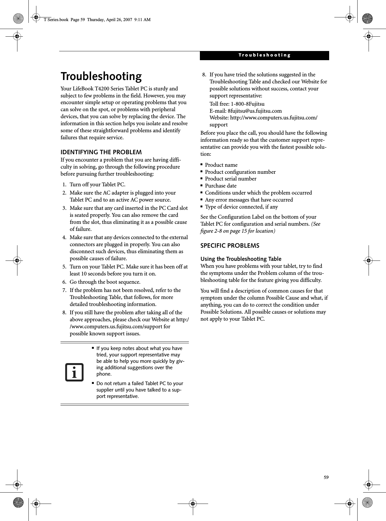
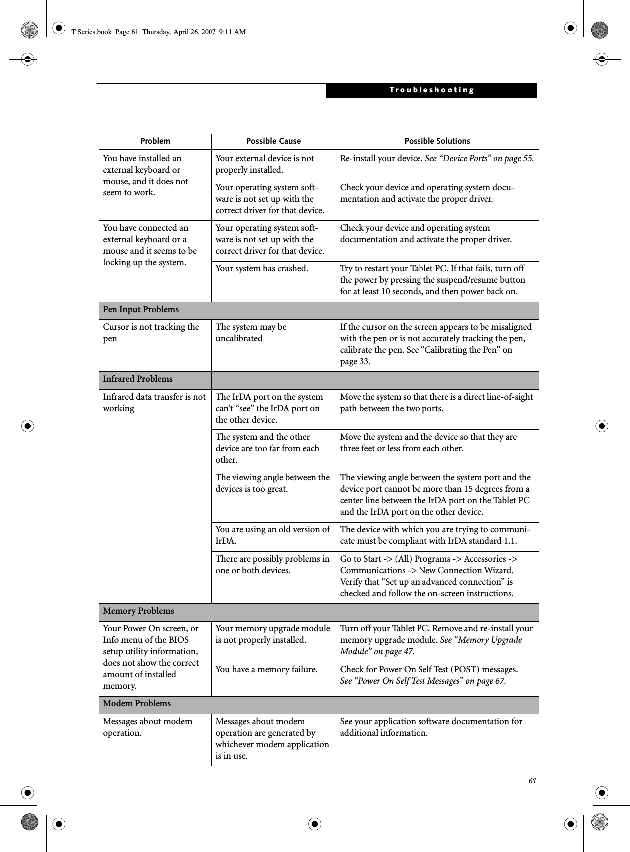
![60LifeBook T4200 Series Tablet PC - Section FiveTROUBLESHOOTING TABLEProblem PageAudio Problems . . . . . . . . . . . . . . . . . . . . . . . . . . page 60Docking Problems . . . . . . . . . . . . . . . . . . . . . . . . page 60Hard Drive Problems . . . . . . . . . . . . . . . . . . . . . . page 60Keyboard or Mouse Problems. . . . . . . . . . . . . . . page 60Pen Input Problems . . . . . . . . . . . . . . . . . . . . . . . page 61Infrared Problems . . . . . . . . . . . . . . . . . . . . . . . . page 61Memory Problems . . . . . . . . . . . . . . . . . . . . . . . . page 61Problem PageModem Problems. . . . . . . . . . . . . . . . . . . . . . . . . page 61USB Device Problems . . . . . . . . . . . . . . . . . . . . . page 62PC Card Problems . . . . . . . . . . . . . . . . . . . . . . . . page 62Power Failures . . . . . . . . . . . . . . . . . . . . . . . . . . . page 62Shutdown and Startup Problems . . . . . . . . . . . . page 64Video Problems . . . . . . . . . . . . . . . . . . . . . . . . . . page 65Miscellaneous Problems . . . . . . . . . . . . . . . . . . . page 66Problem Possible Cause Possible SolutionsAudio ProblemsThere is no sound coming from the built-in speakers.The software volume control is set too low.Adjust the sound volume control settings in your software, operating system and applications.Headphones are plugged into your Tablet PC.Plugging in headphones disables the built-in speakers, remove the headphones.Software driver is not config-ured correctly.Refer to your application and operating system documentation for help.Sound could have been muted with function keys.Press [F3] while holding the [Fn] key to toggle the sound on and off.Port Replicator ProblemsTablet PC does not turn on when installed in optional Port ReplicatorPort Replicator AC adapter is not plugged in. Provide power to the Port Replicator.Tablet PC is not properly seated in the Port Replicator.Remove and re-dock your Tablet PC.Hard Drive ProblemsYou cannot access your hard drive.The setup utility is incorrectly set for your internal (Primary Master) hard drive.Revise BIOS settings to set the Primary Mastercorrectly. See “BIOS Setup Utility” on page 40.The wrong drive designator was used by an application when a bootable CD-ROM was used to start the Tablet PC.Verify drive designator used by application is inuse by the operating system. When the operating system is booted from a CD, drive designationsare automatically adjusted. Security is set so your oper-ating system cannot be started without a password.Verify your password and security settings.Keyboard or Mouse ProblemsThe built-in keyboard does not seem to work.The Tablet PC has gone into Standby mode.Push the Suspend/Resume button.Your application has locked out your keyboard.Try to use your integrated pointing device to restart your system. If this fails, turn your Tablet PC off by pressing the suspend/resume button for 10 seconds or more, and then turn it back on.The NumLock key has been toggled on.Press the NumLock key to toggle it off.T Series.book Page 60 Thursday, April 26, 2007 9:11 AM](https://usermanual.wiki/Fujitsu-Client-Computing/WB0047/User-Guide-790092-Page-69.png)
![62LifeBook T4200 Series Tablet PC - Section FiveModem does not appear to work.Modem may not have been initialized.Verify that the modem has been initialized by the operating system. To do so, right-click on My Computer and select the Hardware tab. Click [Device Manager] and click on the “+” symbol that appears next to Modems. Verify that your device is listed as installed.USB Device ProblemsYou have installed a USB device, but your Tablet PC does not recognize the device, or the device does not seem to work properly.The device is not properly installed.Remove and re-install the device. See “Device Ports” on page 55.The device may have been installed while an application was running, so your Tablet PC is not aware of its installation.Close the application and restart your Tablet PC.Your software may not have the correct software driver active.See your software documentation and activate the correct driver.Your device and another device are assigned the same I/O address.Check all I/O addresses located within the BIOS setup utility and any other installed hardware or software to make sure there are no duplications.PC Card ProblemsA card inserted in the PC Card slot does not work or is locking up the system.The card is not properly inserted.Remove and re-insert the card. See “PC Cards” on page 51.The card may have been inserted while an application was running, so your Tablet PC is not aware of its insertion.Close the application and restart your Tablet PC.Your software may not have the correct software driver active.See your software documentation and activate the correct driver.Your PC Card device and another device are assigned the same I/O address.Check all I/O addresses located within the BIOS setup utility and any other installed hardware or software to make sure there are no duplications.Power FailuresYou turn on your Tablet PC and nothing seems to happen.The installed battery is completely discharged or there is no power adapter (AC or Auto/Airline) installed.Check the Status Indicator Panel to determine the presence and condition of the battery. See “Status Indicator Panel” on page 16. Install a charged battery or a Power adapter.The battery is installed but is faulty.Use the Status Indicator Panel to verify the presence and condition of the battery. See “Status Indicator Panel” on page 16. If a battery is indicating a short, remove that battery and operate from another power source or replace that battery.Problem Possible Cause Possible SolutionsT Series.book Page 62 Thursday, April 26, 2007 9:11 AM](https://usermanual.wiki/Fujitsu-Client-Computing/WB0047/User-Guide-790092-Page-71.png)
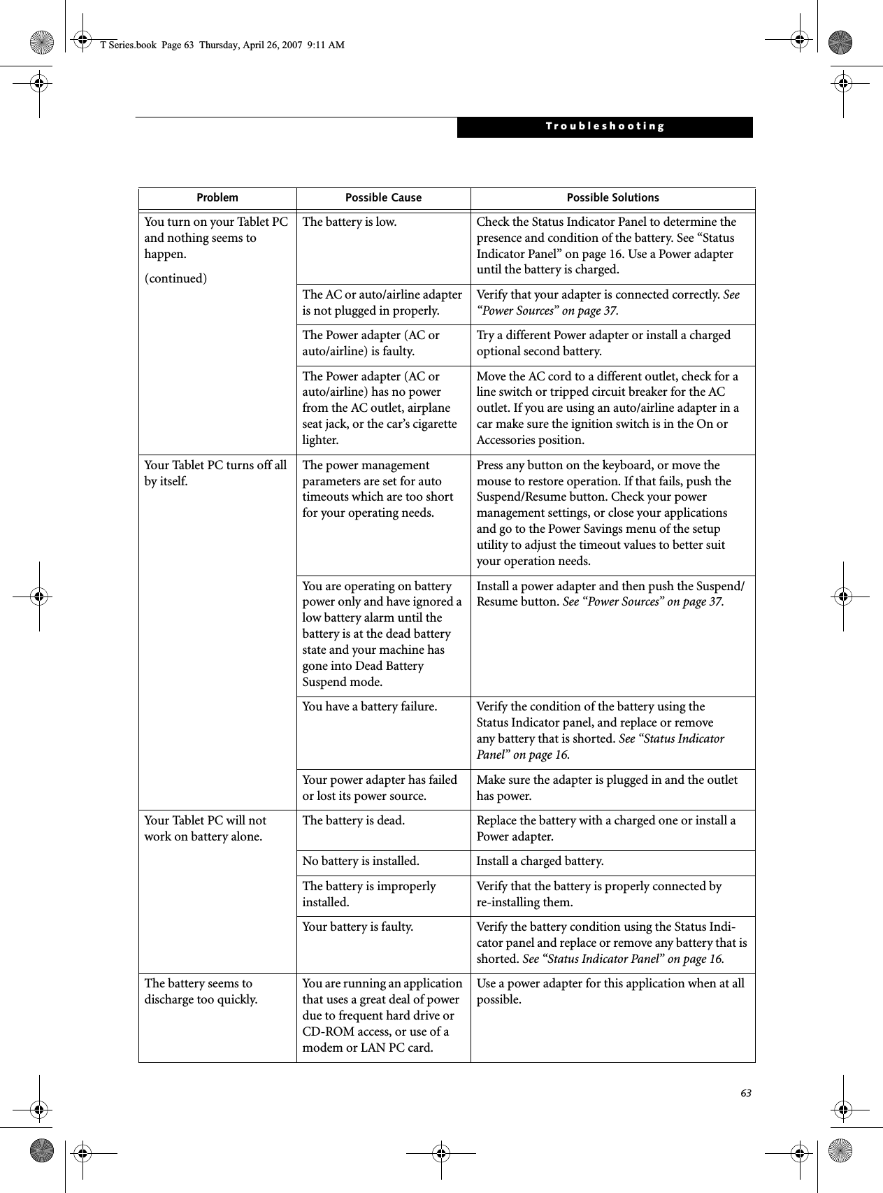
![64LifeBook T4200 Series Tablet PC - Section FiveThe battery seems to discharge too quickly.(continued)The power savings features may be disabled.Check the power management and/or setup utility settings in the Power Savings menu and adjust according to your operating needs.The brightness is turned all the way up.Turn down the brightness adjustment. The higher the brightness the more power your display uses.The battery is very old. Replace the battery.The battery has been exposed to high temperatures.Replace the battery.The battery is too hot or too cold. Restore the Tablet PC to normal operating tempera-ture. The Charging icon on the Status Indicator panel will flash when the battery is outside itsoperating range.The AC Adapter is defective. Replace with another AC Adapter to see if the problem persists. Replace any defective AC Adapters.Shutdown and Startup ProblemsThe Suspend/Resume button does not work.The Suspend/Resume button is disabled from the Advanced submenu of the Power menu of the setup utility. Enable the button from the setup utility.You did not hold the button in long enough.Hold the button longer. This may need to be a few seconds if your application is preventing the CPU from checking for button pushes.There may be a conflict with the application software.Close all applications and try the button again.The system powers up, and displays power-on information, but fails to load the operating system.The boot sequence settings of the setup utility are not compatible with your configuration.Set the operating source by pressing the [F2] key while the Fujitsu logo is on screen, entering the setup utility and adjusting the source settings from the Boot menu. See “BIOS Setup Utility” on page 40.You have a secured system requiring a password to load your operating system.Make sure you have the right password. Enter the setup utility and verify the Security settings and modify them as accordingly. See “BIOS Setup Utility” on page 40.An error message is displayed on the screen during the Tablet PC boot sequence.Power On Self Test (POST) has detected a problem.See the Power On Self Test (POST) messages to determine the meaning and severity of the problem. Not all messages are errors; some are simply status indicators. See “Power On Self Test Messages” on page 67.Your system display won’t turn on when the system is turned on or when the system has resumed.The system may be password-protected.Check the status indicator panel to verify that the Security icon is blinking. If it is blinking, enter your password.Problem Possible Cause Possible SolutionsT Series.book Page 64 Thursday, April 26, 2007 9:11 AM](https://usermanual.wiki/Fujitsu-Client-Computing/WB0047/User-Guide-790092-Page-73.png)
![65TroubleshootingYour Tablet PC appears to change setup parameters when you start it.BIOS setup changes were not saved when you made them and exited the BIOS setup utility returning it to previous settings.Make sure you select Save Changes And Exit when exiting the BIOS setup utility.The BIOS CMOS back-up battery has failed.Contact your support representative for repairs. This is not a user-serviceable part.Video ProblemsThe built-in display is blank when you turn on your Tablet PC.The angle of the display and the brightness settings are not adequate for your lighting conditions.Move the display and the brightness control until you have adequate visibility.The optional Port Replicator is attached, an external monitor is plugged in, and the Tablet PC is set for an external monitor only.Pressing [F10] while holding down the [Fn] key allows you to change your selection of where tosend your display video. Each time you press the combination of keys you will step to the nextchoice. The choices, in order are: built-in display only, external monitor only, both built-in display and external monitor.The power management timeouts may be set for very short intervals and you failed to notice the display come onand go off again.Press any button the keyboard, or move the mouse to restore operation. If that fails, push the Suspend/Resume button. (The display may be shut off by Standby mode, Auto Suspend or Video Timeout)The Tablet PC turned on with a series of beeps and your built-in display is blank.Power On Self Test (POST)has detected a failure which does not allow the displayto operate. Contact your support representative.Your system display won’t turn on when the system is turned on or when the system has resumed.The system may be password-protected.Check the status indicator panel to verify that the Security icon is blinking. If it is blinking, enter your password.The display goes blank by itself after you have been using it.The Tablet PC has gone into Video Timeout, Standby Mode, or Hibernate Mode because you have not used it for a period of time.Press a button on the keyboard, or move the mouse to restore operation. If that fails, push the Suspend/Resume button. Check your power management settings, or close your applications and go to the Power Savings menu of the setup utility to adjust the timeout values to better suit your operation needs. See “BIOS Setup Utility” on page 40.The power management time-outs may be set for very short intervals and you failed to notice the display come onand go off again.Press any button on the keyboard, or move the mouse to restore operation. If that fails, push the Suspend/Resume button. (The display may be shut off by Standby Mode, Auto Suspend or Video Timeout)The display does not close. A foreign object, such as a paper clip, is stuck between the display and the keyboard.Remove all foreign objects from the keyboard.Problem Possible Cause Possible SolutionsT Series.book Page 65 Thursday, April 26, 2007 9:11 AM](https://usermanual.wiki/Fujitsu-Client-Computing/WB0047/User-Guide-790092-Page-74.png)
![66LifeBook T4200 Series Tablet PC - Section FiveThe display has bright or dark spots.If the spots are very tiny and few in number, this is normal for a large LCD display.This is normal; do nothing.If the spots are numerous or large enough to interfere with your operation needs.The display needs technical diagnosis; contact your support representative.The application display uses only a portion of your screen and is surrounded by a dark frame.You are running an application that does not support 800 x 600/1024 x 768 pixel resolution display and display compres-sion is enabled.When compensation is disabled, a clearer but smaller display for applications that do not support 800 x 600/1024 x 768 pixel resolution will result. You can fill the screen but have less resolution by changing your compensation setting. (See the Video Features submenu, located within the Advanced menu of the BIOS. See “BIOS Setup Utility” on page 40.You have connected an external monitor and it does not display any information.Your BIOS setup is not set to enable your external monitor.Try toggling the video destination by pressing [Fn] and [F10] together, or check your BIOS setup and enable your external monitor. (See the Video Features submenu, located within the Advanced Menu of the BIOS. See “BIOS Setup Utility” on page 40.Your external monitor is not properly installed. Reinstall your device. See “External Video Port” on page 56.Your operating system soft-ware is not set up with the correct software driver forthat device.Check your device and operating systemdocumentation and activate the proper driver.You have connected an external monitor and it does not come on.Your external monitor may not be compatible with your Tablet PC.See your monitor documentation and the External Monitor Support portions of the Specifications section. See “Specifications” on page 79.Miscellaneous ProblemsAn error message is displayed on the screen during the operation of an application.Application software often has its own set of error message displays. See your application manual and help displays screens for more information. Not all messages are errors some may simply be status.Problem Possible Cause Possible SolutionsT Series.book Page 66 Thursday, April 26, 2007 9:11 AM](https://usermanual.wiki/Fujitsu-Client-Computing/WB0047/User-Guide-790092-Page-75.png)
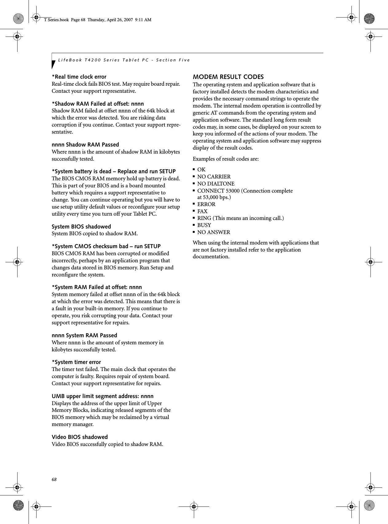
![67TroubleshootingPOWER ON SELF TEST MESSAGESThe following is an alphabetic list of error-and-status messages that Phoenix BIOS and/or your operating system can generate and an explanation of each message. Error messages are marked with an *. If an error message is displayed that is not in this list, write it down and check your operating system documentation both on screen and in the manual. If you can find no reference to the message and its meaning is not clear, contact your support representative for assistance.nnnn Cache SRAM Passed Where nnnn is the amount of system cache in kilobytes successfully tested by the Power On Self Test. (This can only appear if you have an SRAM PC Card installed.)*Extended RAM Failed at offset: nnnn Extended memory not working or not configured prop-erly. If you have an installed memory upgrade module, verify that the module is properly installed. If it is prop-erly installed, you may want to check your Windows Setup to be sure it is not using unavailable memory until you can contact your support representative.nnnn Extended RAM Passed Where nnnn is the amount of memory in kilobytes successfully tested.*Failing Bits: nnnn The hex number nnnnThis is a map of the bits at the memory address (in System, Extended, or Shadow memory) which failed the memory test. Each 1 (one) in the map indicates a failed bit. This is a serious fault that may cause you to lose data if you continue. Contact your support representative.*Fixed Disk x Failure or Fixed Disk Controller Failure (where x = 1-4) The fixed disk is not working or not configured prop-erly. This may mean that the hard drive type identified in your setup utility does not agree with the type detected by the Power On Self Test. Run the setup utility to check for the hard drive type settings and correct them if necessary. If the settings are OK and the message appears when you restart the system, there may be a serious fault which might cause you to lose data if you continue. Contact your support representative.*Invalid NVRAM media typeProblem with NVRAM access. In the unlikely case that you see this message you may have some display prob-lems. You can continue operating but should contact your support representative for more information.*Keyboard controller error The keyboard controller test failed. You may have to replace your keyboard or keyboard controller but may be able to use an external keyboard until then. Contact your support representative.*Keyboard error Keyboard not working. You may have to replace your keyboard or keyboard controller but may be able touse an external keyboard until then. Contact your support representative.*Keyboard error nn BIOS discovered a stuck key and displays the scan code for the stuck key. You may have to replace your keyboard but may be able to use an external keyboard until then. Contact your support representative.*Operating system not found Operating system cannot be located on either drive A: or drive C: Enter the setup utility and see if both the fixed disk, and drive A: are properly identified and that the boot sequence is set correctly. Unless you have changed your installation greatly, the operating system should be on drive C:. If the setup utility is correctly set, your hard drive may be corrupted and your system may have to be re-installed from your back up media.*Parity Check 1 nnnn Parity error found in the system bus. BIOS attempts to locate the address and display it on the screen. If it cannot locate the address, it displays “????”. This is apotentially data destroying failure. Contact yoursupport representative.*Parity Check 2 nnnn Parity error found in the I/O bus. BIOS attempts to locate the address and display it on the screen. If it cannot locate the address, it displays “????”. This is apotentially data destroying failure. Contact yoursupport representative.*Press <F1> to resume, <F2> to SETUP Displayed after any recoverable error message. Pressthe [F1] key to continue the boot process or the [F2]key to enter Setup and change any settings.*Previous boot incomplete – Default configuration used Previous Power On Self Test did not complete success-fully. The Power On Self Test will load default values and offer to run Setup. If the previous failure was caused by incorrect values and they are not corrected, the next boot will likely fail also. If using the default settings does not allow you to complete a successful boot sequence, you should turn off the power and contact your support representative.T Series.book Page 67 Thursday, April 26, 2007 9:11 AM](https://usermanual.wiki/Fujitsu-Client-Computing/WB0047/User-Guide-790092-Page-76.png)
![69TroubleshootingRestoring Your Pre-installed SoftwareThe Drivers and Applications Restore (DAR) DVD contains sets of device drivers and Fujitsu utilities (in specific directories) that are unique to your Tablet PC configuration for use as documented below.RE-INSTALLING INDIVIDUAL DRIVERS AND APPLICATIONS The Drivers and Applications CD can be used to selec-tively re-install drivers and/or applications that may have been un-installed or corrupted. To re-install drivers and/or applications:1. Boot up the system and insert the DAR CD after Windows has started. A Fujitsu Installer screen is displayed after the CD is inserted.2. After reading the License Agreement, click [I agree].3. A window will appear containing a list of applica-tions, drivers, and utilities that you can install from the Drivers and Applications CD.4. In the list, check off all the components you want to install. If you want to install all components, click [Select All]. Clicking [Select All] will select all of the blue-coded components; you must select grey and green components separately.5. Once you have selected the components you wish to install, click [Install Selected Subsystems]; the components will be installed.6. After the components are installed, click [OK], then click [Yes] when asked if you want to reboot the system. RESTORING THE FACTORY IMAGEThe Restore Disc that came with your system contains two utilities:■The Recovery utility allows you to restore the original contents of the C: drive.■The Hard Disk Data Delete utility on this disc is used to delete all data on your hard disk and prevent it from being reused. Do not use Hard Disk Data Delete unless you are absolutely certain that you want to erase your entire hard disk, including all partitions.BOOT Priority ChangeBefore restoring an image, you must first verify that your system is set up to boot from the DVD drive. To verify/change the boot-up priority (rather than booting-up from the hard drive or an external floppy disk drive), perform the following steps:1. Start your system and press the [F2] key when the Fujitsu logo appears. You will enter the BIOS Setup Utility.2. Using the arrow keys, go to the Boot menu.3. Arrow down to the Boot Device Priority submenu. Press [Enter].4. If “Optical Media Drive” or “CD-ROM Drive” is not at the top of the list, arrow down to the drive in the list, and press the space bar (or the + key) to move it to the top of the list. (The system attempts to boot from the devices in the order in which they are listed.). Note that the BIOS for some systems will indicate “CD-ROM Drive”, even when a DVD drive is connected.In order to install applications and/or drivers from the DAR DVD, you will need access to a DVD drive. If you do not have a built-in DVD drive, you will need to connect an external DVD drive to your system.If you have access to the internet, visit the Fujitsu Support website at http://www.computers.us.fujitsu.com/support to check for the most current information, drivers and hints on how to perform recovery and system updates.There may be certain free third-party applications pre-installed on your system that are not on the DAR CD. The latest versions of the applications can be downloaded from the third-party’s website.The components listed are color-coded in terms of their install status. Blue indicates that the component can be installed. Green indicates that the component needs to be installed separately. Grey indicates a component that is already installed; grey items can be reinstalled, but prior to installation you will receive a reminder that the component is already installed and may need to be uninstalled prior to reinstallation.• The use of this disc requires that you have a device capable of reading DVDs attached to your system. If you do not have a built-in DVD player, you will need to attach an external player. For more information on available external devices, visit our Website at: us.fujitsu.com/computers. • This disc can only be used with the system with which it was purchased.T Series.book Page 69 Thursday, April 26, 2007 9:11 AM](https://usermanual.wiki/Fujitsu-Client-Computing/WB0047/User-Guide-790092-Page-78.png)
![70LifeBook T4200 Series Tablet PC - Section Five5. If you have an external DVD drive connected, proceed to step 6; otherwise, proceed to step 7.6. If you have an external DVD drive connected:■Select the Advanced menu in the BIOS window.■Scroll down to the USB Features submenu and press the Enter key to open it.■If Legacy USB Support is disabled, press the space bar to enable it.■Scroll down to SCSI SubClass Support and press the space bar to enable it. 7. Press [F10], then click on [Yes] to exit the BIOS Setup Utility and return to the boot process.After you have changed the boot priority, you can restore a backup image when you are booting up.Procedure1. Turn on the power to your system.2. Ensure that you have a device that can read DVDs either installed in your system or attached exter-nally to it.3. Insert the Restore Disc into the drive tray.4. Reboot your system.5. After the system reboots, follow the instructions that appear to either restore your system image or erase all data from your hard disk.AUTOMATICALLY DOWNLOADING DRIVER UPDATESYour system has a convenient tool called the Fujitsu Driver Update (FDU) utility. With FDU, you can choose to automatically or manually go to the Fujitsu site to check for new updates for your system.The FDU icon should appear in the system tray at the bottom right of your screen (roll the cursor over the icons to find the correct one). If the FDU icon does not appear in the system tray, it can be started by going to [Start] -> All Programs, and clicking on Fujitsu Driver Update; this will create the icon automatically.To invoke the FDU menu, right-click on the FDU icon. The menu contains the following items:■Check for updates nowAllows for manual driver update search. The first time it is used, you are prompted to agree to a user agreement. After clicking on the icon, the FDU auto-matically connects with the Fujitsu site to check for updates and downloads them. While downloading, the icon has a red bar through it, indicating that it cannot be used while the download is in process. When the update is complete, a message appears informing you of the fact.■Enable Automatic Update NotificationsAutomatically searches for new updates on a regular basis (approximately every 3 days).■Show update historyBrings up a screen that displays a history of updates that have been made via the FDU.■About Fujitsu Driver UpdateDisplays the FDU version number and copyright information■Fujitsu Driver Update ReadmeDisplays the FDU readme.WINDOWS VISTA USERS: IMPORTANT NOTE - While the operating system is booting up during the restoration procedure, your screen will go blank for a short period of time. This is normal. During the period while your screen is blank, do not press any buttons. Please wait for the “Set Up Windows” screen to be displayed, then follow the instructions that appear.T Series.book Page 70 Thursday, April 26, 2007 9:11 AM](https://usermanual.wiki/Fujitsu-Client-Computing/WB0047/User-Guide-790092-Page-79.png)


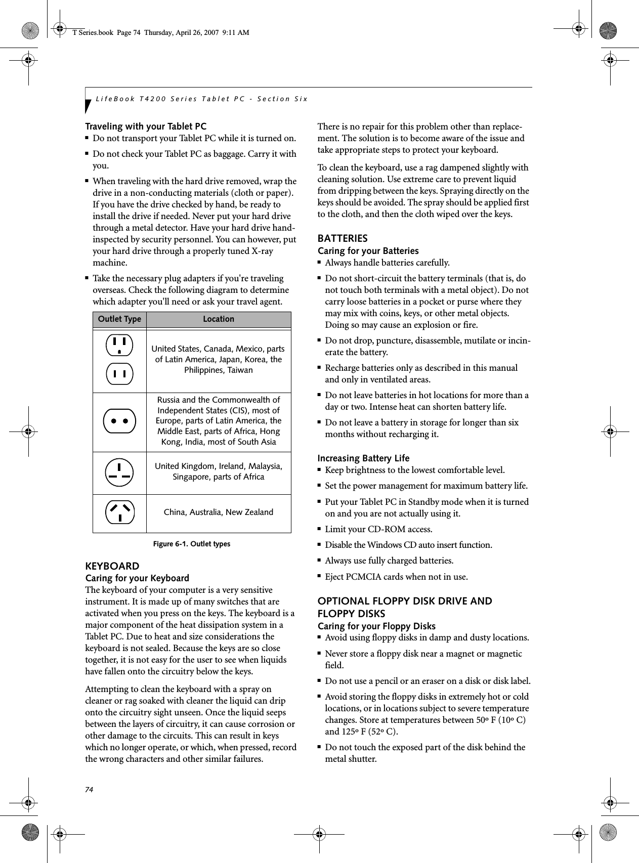


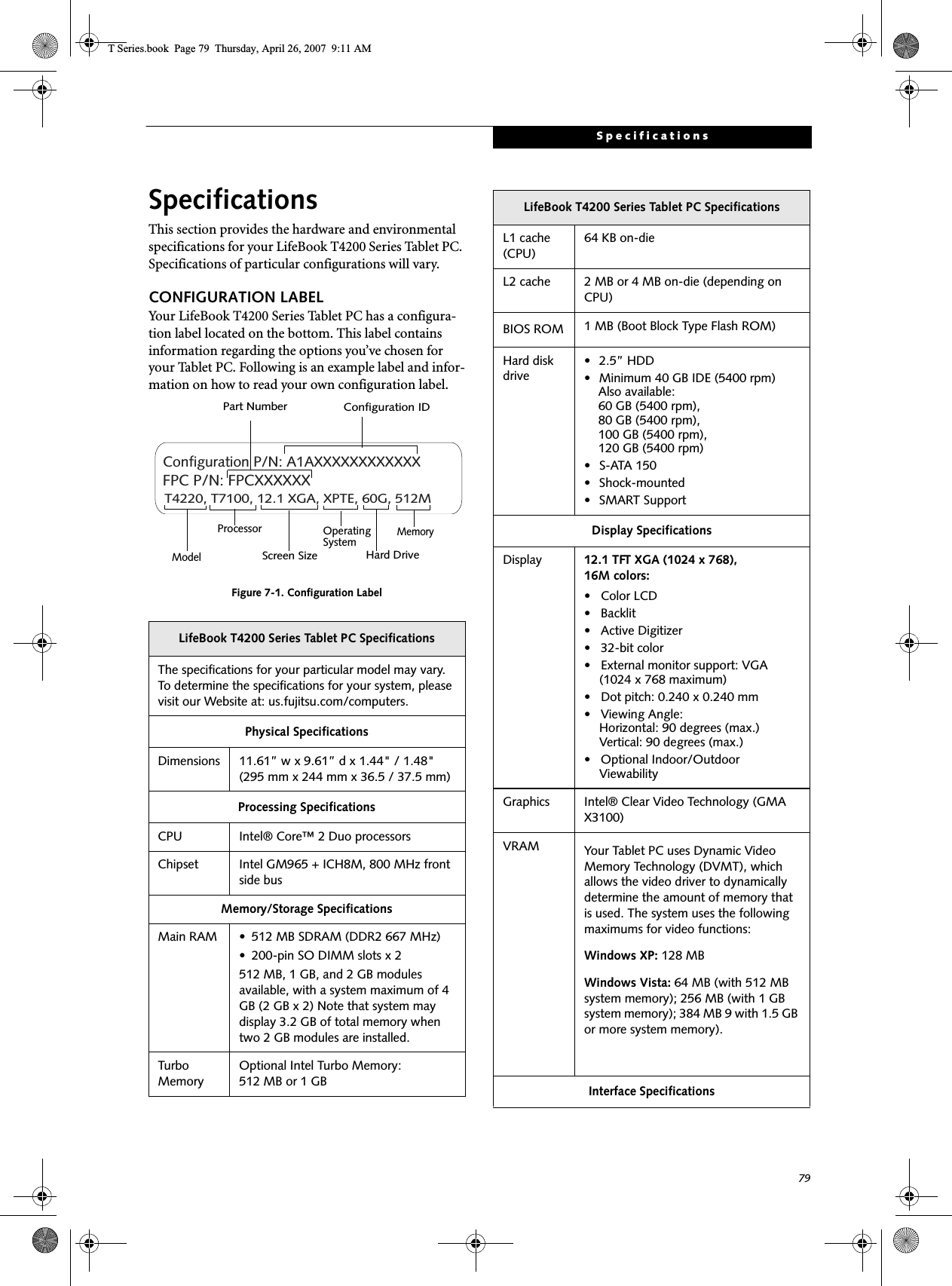
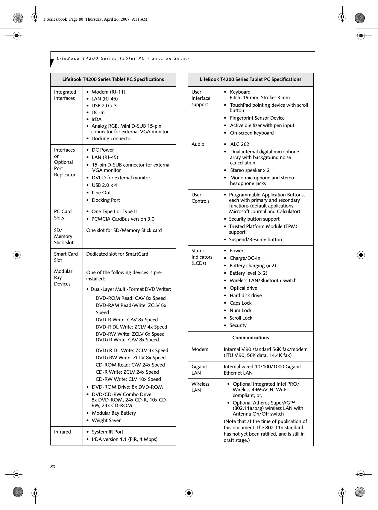
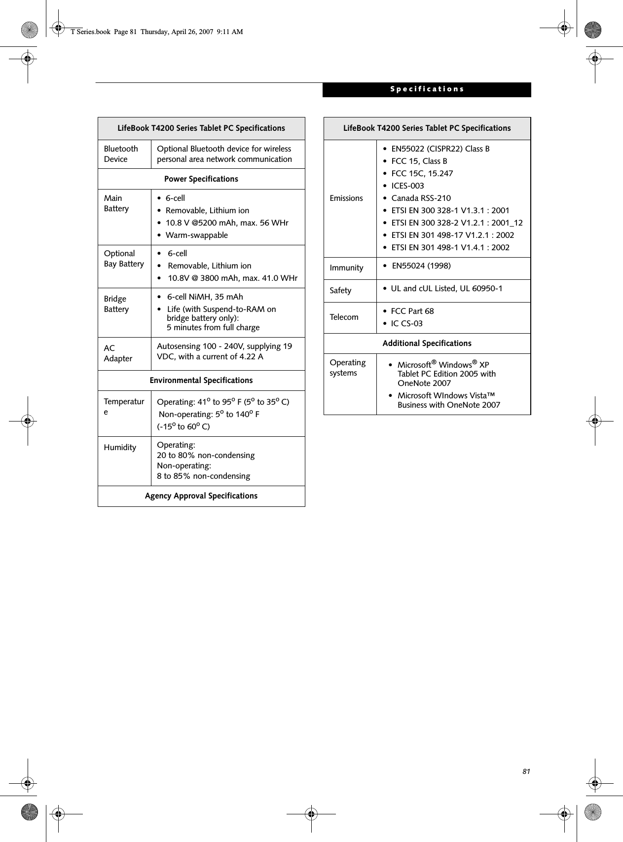


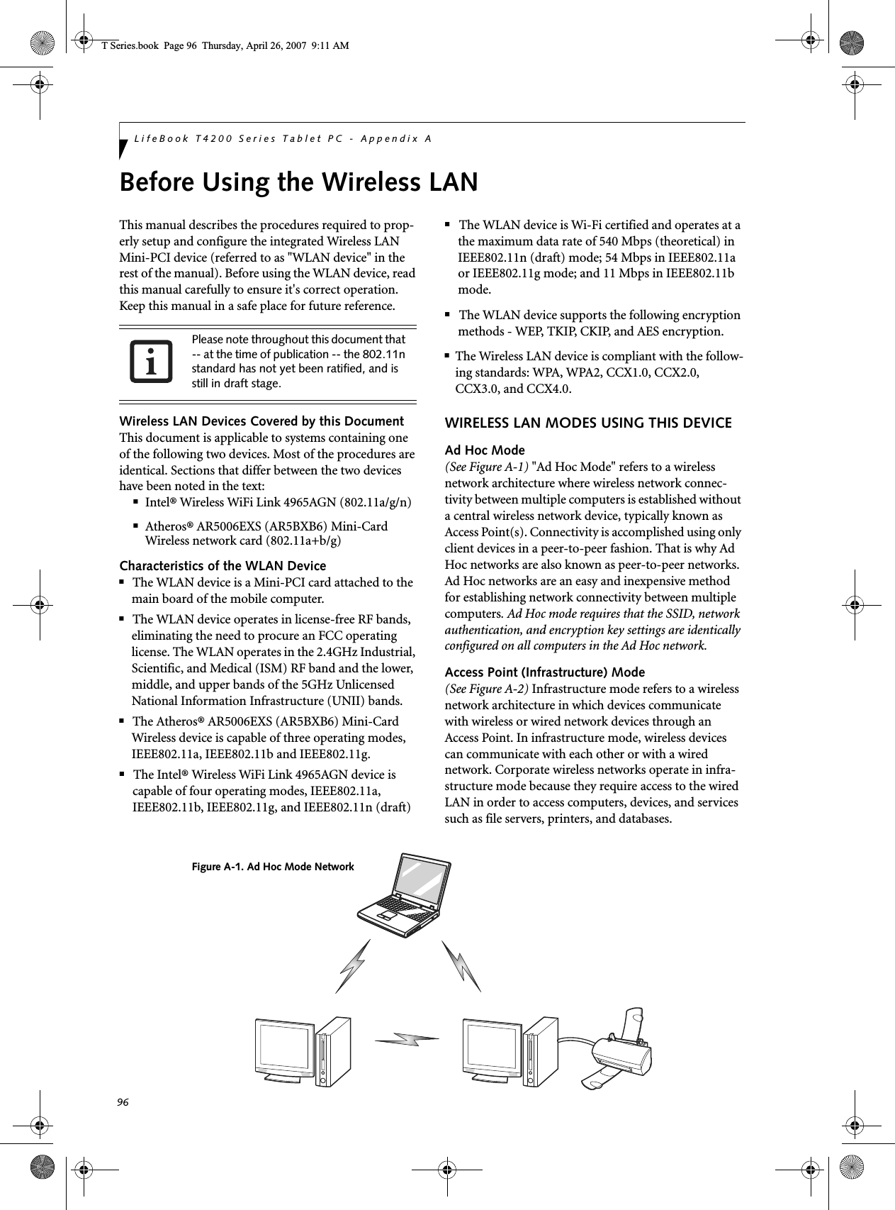
![97Wireless LAN User’s Guide How to Handle This DeviceThe WLAN device comes pre-installed in your mobile computer. Under normal circumstances, it should not be necessary for you to remove or re-install it. The Oper-ating System that your mobile computer comes with has been pre-configured to support the WLAN device. WIRELESS NETWORK CONSIDERATIONS■The Intel PRO/Wireless 3945ABG WLAN device sup-ports IEEE802.11a, IEEE802.11b and IEEE802.11g.■Intel Wireless WiFi Link 4965AGN (4965AGN) device supports IEEE802.11a, IEEE802.11b, IEEE802.11g, and IEEE802.11n.■The WLAN device operates in the 2.4GHz ISM band and the 5 GHz lower, middle, and upper UNII bands.■Microwave ovens may interfere with the operation of WLAN devices since they operate in the same 2.4GHz frequency range as IEEE802.11b/g/n devices. Interfer-ence by microwaves does not occur with IEEE802.11a radio which operates in the 5 GHz RF band.■Wireless devices that transmit in the 2.4GHz range may interfere with operation of WLAN devices in IEEE802.11b/g/n modes. Symptoms of interference include reduced throughput, intermittent disconnects, and many frame errors. It is HIGHLY recommended that these interfering devices be powered off to ensure proper operation of the WLAN device.DEACTIVATING THE WLAN DEVICEDeactivation of the WLAN device may be desired in certain circumstances (to extend battery life) or where certain environments require it (i.e. hospitals, clinics, airplanes, etc.). Fujitsu mobile computers employ three methods with which to deactivate the WLAN device:■Using the Wireless On/Off Switch, or,■In Windows Vista, using the WLAN icon in the taskbar, or,■In Windows XP, using the Intel PROSet Software or Atheros Client Utility software.Deactivation using the Wireless On/Off SwitchThe WLAN device can be deactivated quickly and effi-ciently by toggling the Wireless On/Off Switch to the Off position. (Figure A-3)The Wireless LAN/Bluetooth On/Off Switch will power off both the optional wireless LAN and Bluetooth devices at the same time. To enable or disable either one of the devices individually, perform the following steps:1. Slide the Wireless LAN/Bluetooth on/off switch to On position.2. In the Control Panel, double-click the Fujitsu Radio Control icon.3. In the window that appears, click the button associated with Bluetooth and/or Wireless LAN Status to enable or dis-able the individual devices.4. Click [OK].Figure A-2. Access Point (Infrastructure) Mode NetworkADSL modem,cable modem,or similarInternetWired LANAccess Point*Wireless LAN*An optional hub for a wiredLAN may be required dependingupon the type of access point used.T Series.book Page 97 Thursday, April 26, 2007 9:11 AM](https://usermanual.wiki/Fujitsu-Client-Computing/WB0047/User-Guide-790092-Page-106.png)
![98LifeBook T4200 Series Tablet PC - Appendix AThe Wireless LAN/Bluetooth On/Off switch has no effect on systems without wireless devices.Figure A-3. Wireless LAN/Bluetooth SwitchWindows Vista: Deactivation using the icon in the taskbar1. Right-click the WLAN icon in the taskbar at the bottom right of your screen.Choose Disconnect from a network.Windows XP: Deactivation using the Intel PROSet SoftwareThe WLAN device can also be deactivated in Windows using the Intel PROSet Software. The procedure to accomplish this:1. Click [Start]-> [All Programs].2. Select Intel ProSet Wireless, then click on Intel ProSet Wireless from the menu that appears. The Intel ProSet Wireless utility will be displayed.3. At the bottom left corner of the window, select Wireless Off from the dropdown list. Windows XP: Deactivation using Atheros Client Utility software1. Click [Start] -> [Program Files] -> [Atheros] -> Atheros Client Utility.2. Choose Action and click Disable Radio.ACTIVATING THE WLAN DEVICEActivation of the WLAN device can be accomplished using the same methods as the deactivation process■Using the Wireless On/Off Switch■In Windows XP, using the Intel PROSet Software or Atheros Software.■In Windows Vista, by right-clicking the WLAN icon then clicking “Connect to a network”Wireless LAN/Bluetooth On/Off SwitchT Series.book Page 98 Thursday, April 26, 2007 9:11 AM](https://usermanual.wiki/Fujitsu-Client-Computing/WB0047/User-Guide-790092-Page-107.png)
![99Wireless LAN User’s Guide Configuration of the WLAN DeviceThe optional WLAN Device can be configured to estab-lish wireless network connectivity using one of the following tools:■Intel PROSet Software - The Intel PROSet Software allows for multiple profile setup and supports auto-matic profile switching. Support for most industry standard security solutions is contained in this soft-ware.■Atheros Client Utility - The Atheros Client Utility soft-ware allows for multiple profile setups and supports automatic profile switching. Support for most indus-try standard security solutions is contained in this software.There are two procedures outlines below. The first one is for use with the Windows Vista operating system, and the other is used with the Windows XP operating system.CONFIGURING THE WLAN WITH WINDOWS VISTAThe WLAN device can be configured to establish wire-less network connectivity using the software that is built into Windows Vista. Support for most industry standard security solutions is contained in this software.Pre-defined parameters will be required for this proce-dure. Please consult with your network administrator for these parameters:1. Click the Start button, then select Control Panel.2. If the Control Panel is not in Classic View, select Classic View from the left panel. Double-click the Network and Sharing Center icon.3. Select “Manage wireless networks” from the left panel.4. Click on the [Add] button.5. Depending upon what type of connection you would like to make, make a selection. For an infra-structure network, select “Manually create a net-work profile. For ad hoc network, select “Create an ad hoc network”.6. Enter the required information. It may be necessary to consult with your network administrator for some of the information.7. In the event you require assistance, go to the Net-work and Sharing Center window (Start -> Control Panel -> Network and Sharing Center), and type in relevant keywords in the Search box. Connecting to a Network with Windows VistaAfter you have configured your computer, you can connect to an active network by performing the following steps:1. Click on the WLAN icon in the system tray.2. Select “connect to a network”.Select a network from the list that appears, and click the [Connect] button.CONFIGURING THE WLAN USING WINDOWS XP Configuring Using Intel PROSet SoftwareThis section explains the procedure to properly configure the WLAN device in a system using Windows XP using the Intel PROSet Software. Pre-defined param-eters will be required for this procedure. Please consult with your network administrator for these parameters:Network Name - Also known as the SSIDNetwork Key (WEP) - Required if using static WEP keys. Authentication Type - Open, Shared, WPA, or WPA-PSKProcedure1. Activate the WLAN device using either the Wireless On/Off Switch or the Intel PROSet software.2. Click the [Start] button first and then [All Pro-grams].3. Click the icon [Intel PROSet Wireless] to execute the Intel PROSet Wireless software.4. Click the [Add] button. The General Settings dialog displays. 5. Enter a profile name in the Profile Name field. 6. Enter the network SSID, in the Network Name (SSID) field. 7. Click Infrastructure or Ad Hoc for the operating mode. 8. Click [Advanced].T Series.book Page 99 Thursday, April 26, 2007 9:11 AM](https://usermanual.wiki/Fujitsu-Client-Computing/WB0047/User-Guide-790092-Page-108.png)
![100LifeBook T4200 Series Tablet PC - Appendix A9. The Mandatory Access Point option is only used if Infrastructure mode is selected. Use this option to connect to a specific access point. Enter the MAC address for the access point. Click OK to save the setting and return to the General Settings page. 10. Click [Next].11. If you are using Cisco CCX, click Cisco Options to enable Cisco CKIP data encryption on the Security Settings page. Check the Cisco Compatible Exten-sions Options. If you have checked the Cisco's "Mixed-Cell" box in the Advanced Setting, this option must also be checked.12. Click [OK].13. Click Next.14. Select Open, Shared, WPA-Enterprise, WPA2-Enterprise, WPA-Personal, or WPA2-Personal in the Network Authentication options. 15. Select either None, WEP, CKIP (if Enable Cisco Cli-ent eXtentions is enabled, use CKIP or WEP), or TKIP for the data encryption. 16. If WEP is selected, select either 64 or 128-bit for the Encryption Level. 17. Select the key index 1, 2, 3 or 4. 18. Enter the WEP key if required. If your network does not employ a 802.1x/EAP security mechanism, please skip to step 24.19. Click the Enable 802.1x checkbox to enable the 802.1x security option. Please contact your network administrator if configuration of this setting is required.20. Select the appropriate Authentication Type. Please contact your network administrator if configura-tion of this setting is required.21. After selecting your authentication type, enter the user name, domain, and password of the user you have created on the authentication server. The user name and password do not have to be the same as name and password of your current Windows user login.22. Click [OK] to save the settings.23. From the Intel ProSet Wireless page, click the new profile name shown in the Profile List. Use the up and down arrows to position the priority of the new profile in the priority list. 24. Click the Connect button to connect to the net-work. 25. Click [Close] if you want to close the Intel PROSet for Wireless window.Configuring Using Atheros Client Utility SoftwareThis section explains the procedure to properly configure the WLAN device using the Atheros Client Utility. Pre-defined parameters will be required for this procedure. Please consult with your network adminis-trator for these parameters:Network Name - Also known as the SSIDNetwork Key (WEP) - Required if using static WEP keys. Authentication Type - Open, Shared, WPA, or WPA-PSKProcedure1. Activate the WLAN device using either the Wireless On/Off Switch or the Atheros Client Utility2. Right-click on the “Atheros Client Utility” icon in the system tray, and select “Open Atheros Client Utility” from the menu.3. From the Current Status page, click the Profile Management tab. 4. If this is your first time using this utility, highlight the profile [Default] and Click the [Modify] button, otherwise Click the [New] button. The General Set-tings dialog displays. 5. From the General page, enter a profile name in the Profile Name field. 6. Enter the network SSID, in the SSID1 field. If you wish to create a profile that can connect to up to 3 different wireless networks, SSID's can be entered in the SSID2 and SSID3 fields as well.7. Click the Security tab. 8. The Security tab allows for the configuration of the Security modes listed in the table below. Please select the radio button of the desired security mode. If these settings are not known to you, please consult with your network administrator for the correct settings. Field Name DescriptionWPA Enables the use of Wi-Fi Protected Access. Choosing WPA opens the WPA EAP drop-down menu. Options include TLS and PEAP. If these settings are not known to you, please consult with your network administrator for the correct settings. T Series.book Page 100 Thursday, April 26, 2007 9:11 AM](https://usermanual.wiki/Fujitsu-Client-Computing/WB0047/User-Guide-790092-Page-109.png)
![101Wireless LAN User’s Guide 9. Click OK10. Click the Advanced tab11. The Advanced tab allows for the configuration of the options detailed in the table below.12. Click OK13. If the profile you just created does not activate immediately, click the Profile Management tab, highlight the desired Profile, and click Activate.14. Click OK to close the Atheros Client Utility.CONNECTION TO THE NETWORKThis section explains connection to the network.If there is an administrator of the network, contact the network administrator for data settings.Setting the networkPerform the “Setting TCP/IP” and “Confirming the computer and work group names” operations required for network connection.Setting TCP/IP1. Click the [Start] button first and then [Control Panel].2. If the Control Panel is in Category view, switch to Classic view by clicking “Switch to Classic View” under Control Panel the left frame. (If you are already in Classic view, “Switch to Category View” will be displayed.) 3. Double-click [Network Connections]. A list of cur-rently installed networks will be displayed.4. Right-click [Wireless Network Connection] in the list, and then click [Properties] in the menu dis-played. The [Wireless Network Connection Proper-ties] window will be displayed.5. Click the [General] tab if it is not already selected.6. Click [Internet Protocol (TCP/IP] and then click [Properties]. The [Internet Protocol (TCP/IP) Properties] window will be displayed.7. Set the IP address as follows:■For ad hoc connection: Select [Use the following IP address:] and then enter data for [IP address] and [Subnet mask]. See page 108 for IP address setting.■For access point (infrastructure) connection: If your network uses DHCP, select [Obtain an IP address automatically] and [Obtain DNS server address automatically]. If your network uses static IP addresses, consult with your network adminis-trator for the correct IP address settings.8. Click the [OK] button. Processing will return to the [Wireless Network Connection Properties] window.9. Click the [OK] button.10. Close the [Network Connection] window. WPA-PSK Enables WPA-Pre-Shared Key. Click on the Configure button to enter the WPA Passphrase. If these settings are not known to you, please consult with your network administrator for the correct settings. 802.1x Enables 802.1x security. If these settings are not known to you, please consult with your network administrator for the correct settings. Choosing this option opens the 802.1x EAP type drop-down menu. Options include TLS, PEAP, and LEAPPre-Shared Key Enables the use of pre-shared keys that are defined on both the access point and the station. This is where static WEP keys are entered. Click the Configure button to fill in the Define Pre-Shared Keys window.None No securityField Name DescriptionPower Save ModeOptions are Maximum, Normal, or OffNetwork Type Options are AP (Infrastructure) or Ad Hoc802.11b PreambleSpecifies the preamble setting in 802.11b. The default setting is Short and Long (Access Point mode), which allows both short and long headers in the 802.11b frames. Set to Long Only to override allowing short frames.Transmit Power LevelOptions are 100%, 50%, 25%, 12.5% or Lowest transmit power (0mW)Wireless Mode Specifies the wireless mode in an access point network.Wireless Mode when Starting Ad Hoc NetworkSpecifies 5GHz 54 Mbps, 5 GHz 108 Mbps, 2.4 GHz 11 Mbps, or 2.4 GHz 54 Mbps to start an Ad Hoc network if no matching network name is found after scanning all available modes.To change the setting of the IP address, you need to be logged in from Windows as an administrator.T Series.book Page 101 Thursday, April 26, 2007 9:11 AM](https://usermanual.wiki/Fujitsu-Client-Computing/WB0047/User-Guide-790092-Page-110.png)
![102LifeBook T4200 Series Tablet PC - Appendix AFollowing this operation, confirm the names of the computer and the workgroup as follows.Confirming the computer and work group names1. Click the [Start] button, then [Control Panel].2. If the Control Panel is in Category view, switch to Classic view by clicking “Switch to Classic View” under Control Panel the left frame. (If you are already in Classic view, “Switch to Category View” will be displayed.) 3. Double-click the [System] icon. The [System Prop-erties] window will be displayed.4. Click the [Computer Name] tab.5. Confirm the settings of [Full computer name:] and [Workgroup:].a. The setting of [Full computer name:] denotes the name for identifying the computer. Any name can be assigned for each personal computer. Enter the desired name in less than 15 ASCII character code format. Identifiability can be enhanced by entering the model number, the user name, and other factors.b. [Workgroup name] is the group name of the network. Enter the desired name in less than 15 ASCII character code format.For ad hoc connection: Assign the same network name to all personal computers existing on the network.For access point (infrastructure) connection: Assign the name of the work group to be accessed.6. Click the [OK] button. If a message is displayed that requests you to restart the personal computer, click [Yes] to restart the computer.Setting the sharing functionSet the sharing function to make file and/or printer sharing with other network-connected personal computers valid.This operation is not required unless the sharing func-tion is to be used.The folder and printer for which the sharing function has been set will be usable from any personal computer present on the network.Setting the Microsoft network-sharing service1. Click the [Start] button first and then [Control Panel]. 2. If the Control Panel is in Category view, switch to Classic view by clicking “Switch to Classic View” under Control Panel the left frame. (If you are already in Classic view, “Switch to Category View” will be displayed.) 3. Double-click [Network Connections]. A list of cur-rently installed networks will be displayed.4. Right-click [Wireless Network Connection] in the list, and then click [Properties] in the menu dis-played. The [Wireless Network Connection Proper-ties] window will be displayed.5. If [File and Printer Sharing for Microsoft Net-works] is displayed, proceed to step 6. If [File and Printer Sharing for Microsoft Networks] is not dis-played, skip to step 7.6. Make sure that the [File and Printer Sharing for Microsoft Networks] check box is checked, and then click the [OK] button. Skip to “Setting file-sharing function”.7. Click [Install]. The [Select Network Component Type] window will be displayed.8. Click [Service], then click the [Add] button. The [Select Network Service] window will be displayed.9. Click [File and Printer Sharing for Microsoft Net-works] and then click the [OK] button. Processing will return to the [Wireless Network Connection Properties] window, and [File and Printer Sharing for Microsoft Networks] will be added to the list.10. Click the [Close] button.Setting the file-sharing functionThe procedure for setting the file-sharing function follows, with the “work” folder in drive C: as an example.1. Click the [Start] button first and then [My Com-puter]. 2. Double-click [Local disk (C:)].To modify the computer name and/or the work group name, you need to be logged in from Windows as an administrator.To change the name, click [Change] and then proceed in accordance with the instruction messages displayed on the screen.To share a file and/or the connected printer, you need to be logged in as an administrator.T Series.book Page 102 Thursday, April 26, 2007 9:11 AM](https://usermanual.wiki/Fujitsu-Client-Computing/WB0047/User-Guide-790092-Page-111.png)
![103Wireless LAN User’s Guide 3. Right-click the “work” folder (or whichever folder you want to share), and then click [Sharing and Security...] in the menu displayed. The [Folder Name Properties] window will be displayed.4. Click [Sharing] if it isn’t already selected.5. Click the link stating “If you understand the secu-rity risks, but want to share files without running the wizard, click here”.6. Click “Just enable file sharing” and click [OK].7. Check the [Share this folder on the network] check box.8. Click the [OK] button. The folder will be set as a sharable folder, and the display of the icon for the “work.” folder will change.Setting the printer-sharing function1. Click the [Start] button first and then [Printers and FAX]. A list of connected printers will be displayed.2. Right-click the printer for which the sharing func-tion is to be set, and then click [Sharing] in the menu displayed. The property window correspond-ing to the selected printer will be displayed.3. Click the [Sharing] tab.4. Click [Share this printer].5. Enter the sharing printer name in [Share name].6. Click the [OK] button. Confirming connectionAfter you have finished the network setup operations, access the folder whose sharing has been set for other personal computers. Also, confirm the status of the radio waves in case of trouble such as a network connection failure.Connecting your personal computer to another personal computer1. Click [Start] first and then [My Computer]. The [My Computer] window will be displayed in the left frame.2. Click [My Network Places] in the “Other Places” list. The window [My Network Places] will be dis-played.3. Click [View workgroup computers] under Network Tasks in the left frame.4. Double-click the personal computer to which your personal computer is to be connected. The folder that was specified in “Setting the file-sharing func-tion” on page 102 will be displayed.5. Double-click the folder to be accessed.Confirming the status of the radio1. Right-click the Intel PRO Wireless icon in the lower right corner of the screen.2. Click [Open Intel PROSet for Wireless]. The Intel PROSet for Wireless window opens.3. Contained within the General tab and the Details section (accessed by pressing the [Details] button), you will find the current operating status of the radio. (When the radio is turned off or the com-puter is not yet connected, some of the conditions will not be displayed.)■Network Name (SSID)Displays the Network Name (SSID) currently used by the radio.■Profile NameThe current configuration profile is displayed.■ModeDisplays the current operating mode. [Infra-structure (AP)] or [Ad Hoc] will be displayed.Setting the file-sharing function for the file which has been used to execute Network Setup Wizard is suggested on the screen. For the wireless LAN, however, since security is guaranteed by entry of the network name (SSID) and the network key, the steps to be taken to set the file-sharing function easily without using Network Setup Wizard are given below.To specify the corresponding folder as a read-only folder, select the [Read only] checkbox under the General tab.Setting the printer-sharing function when Network Setup Wizard has been executed is suggested on the screen. For the wireless LAN, however, since security is guaranteed by entry of the network name (SSID) and the network key, the steps to be taken to set the printer-sharing function without using Network Setup Wizard are laid down below.In the case of access point (infrastructure) connection, enter the necessary data for the access point before confirming connection. Refer to the manual of the access point for the access point setup procedure.T Series.book Page 103 Thursday, April 26, 2007 9:11 AM](https://usermanual.wiki/Fujitsu-Client-Computing/WB0047/User-Guide-790092-Page-112.png)
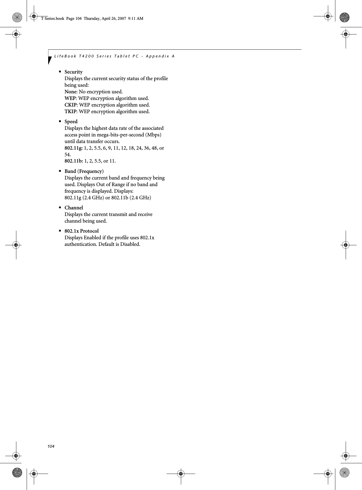
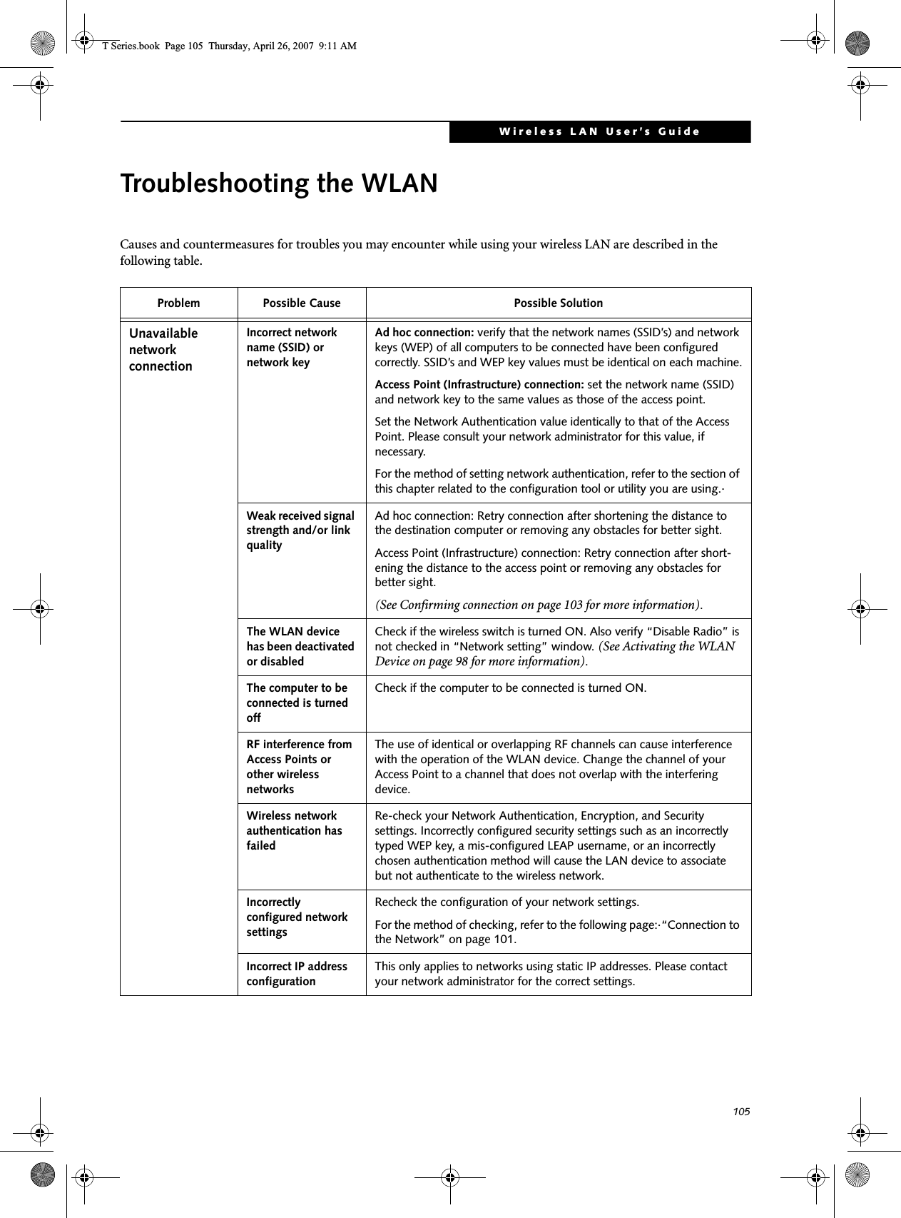
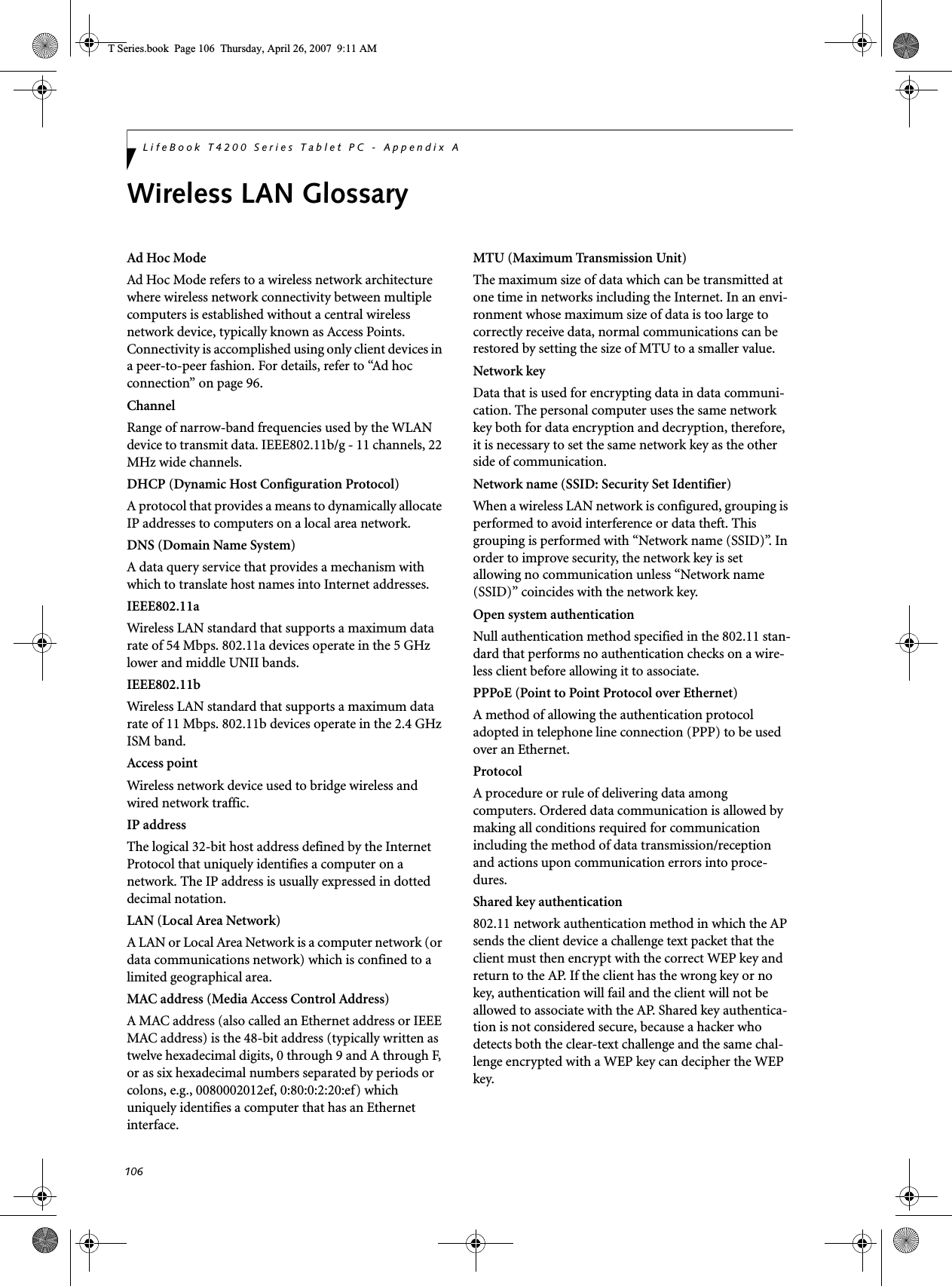
![108LifeBook T4200 Series Tablet PC - Appendix AIP address informationIf IP address is unknown, set IP address as follows:If you have an access point (DHCP server) on the network, set the IP address as follows:[Obtain an IP address automatically]If the IP address is already assigned to the computer in the network, ask the network administrator to check the IP address to be set for the computer.If no access point is found in the network:An IP address is expressed with four values in the range between 1 and 255.Set the each computer as follows: The value in paren-theses is a subnet mask.<Example>Computer A: 192.168.100.2 (255.255.255.0)Computer B: 192.168.100.3 (255.255.255.0)Computer C: 192.168.100.4 (255.255.255.0)::Computer X: 192.168.100.254 (255.255.255.0)IP addressing is much more complicated than can be briefly explained in this document. You are advised to consult with your network administrator for additional information.A DHCP server is a server that automatically assigns IP addresses to computers or other devices in the network. There is no DHCP server for the AdHoc network.T Series.book Page 108 Thursday, April 26, 2007 9:11 AM](https://usermanual.wiki/Fujitsu-Client-Computing/WB0047/User-Guide-790092-Page-117.png)
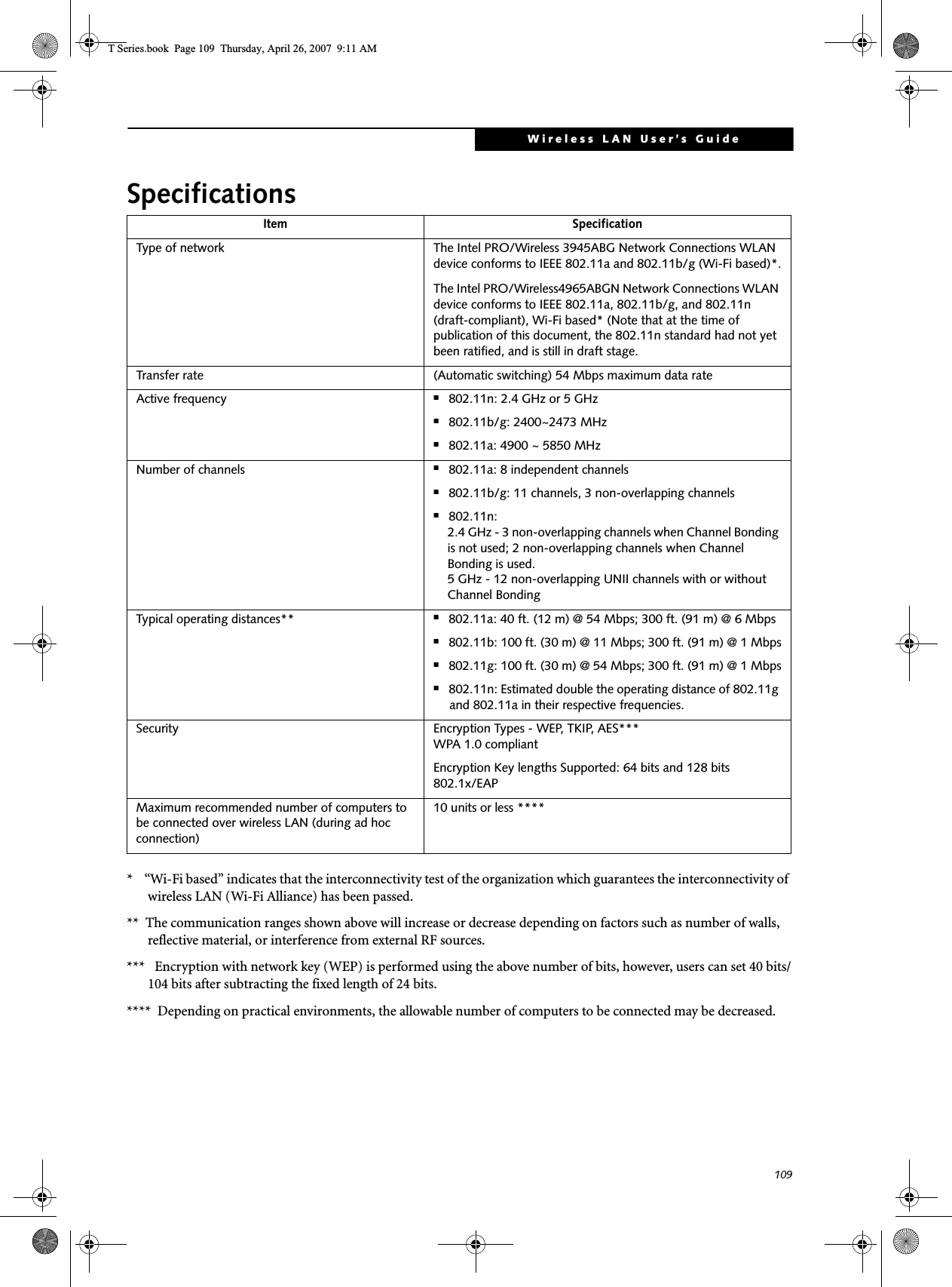
![110LifeBook T4200 Series Tablet PC - Appendix AUsing the Bluetooth DeviceThe Integrated Bluetooth module (EYTF3CSFT) is an optional device available for Fujitsu mobile computers. WHAT IS BLUETOOTH?Bluetooth technology is designed as a short-range wire-less link between mobile devices, such as laptop computers, phones, printers, and cameras. Bluetooth technology is used to create Personal Area Networks (PANs) between devices in short-range of each other. WHERE TO FIND INFORMATIONABOUT BLUETOOTHThe Bluetooth module contains a robust Help user’s guide to assist you in learning about operation of the Bluetooth device.To access the Help file, click [Start] -> All Programs, and click on Toshiba. Select Bluetooth, then select User’s Guide.For additional information about Bluetooth Technology, visit the Bluetooth Website at: www.bluetooth.com.FCC Radiation Exposure StatementThis equipment complies with FCC radiation exposure limits set forth for an uncontrolled environment. The Bluetooth antenna is locateat the center of the top edge of the LCD screen and is exempt from minimum distance criteria due to its low power. The transmitters in this device must not be co-located or operated in conjunction with any other antenna or transmitter.Canadian NoticeTo prevent radio interference to the licensed service, this device is intended to be operated indoors and away from windows to provide maximum shielding. Equipment (or its transmit antenna) that is installed outdoors is subject to licensing.WarrantyUsers are not authorized to modify this product. Any modifications invalidate the warranty.This equipment may not be modified, altered, or changed in any way without signed written permission from Fujitsu. Unauthorized modification will void the equipment authorization from the FCC and Industry Canada and the warranty.The Wireless LAN/Bluetooth On/Off Switch will power off both the optional wireless LAN and Bluetooth devices at the same time. To enable or disable either one of the devices individually, perform the following steps:1. Slide the Wireless LAN/Bluetooth on/off switch to On position.2. In the Control Panel, double-click the Fujitsu Radio Control icon.3. In the window that appears, click the button associated with Bluetooth and/or Wireless LAN Status to enable or dis-able the individual devices.4. Click [OK].T Series.book Page 110 Thursday, April 26, 2007 9:11 AM](https://usermanual.wiki/Fujitsu-Client-Computing/WB0047/User-Guide-790092-Page-119.png)


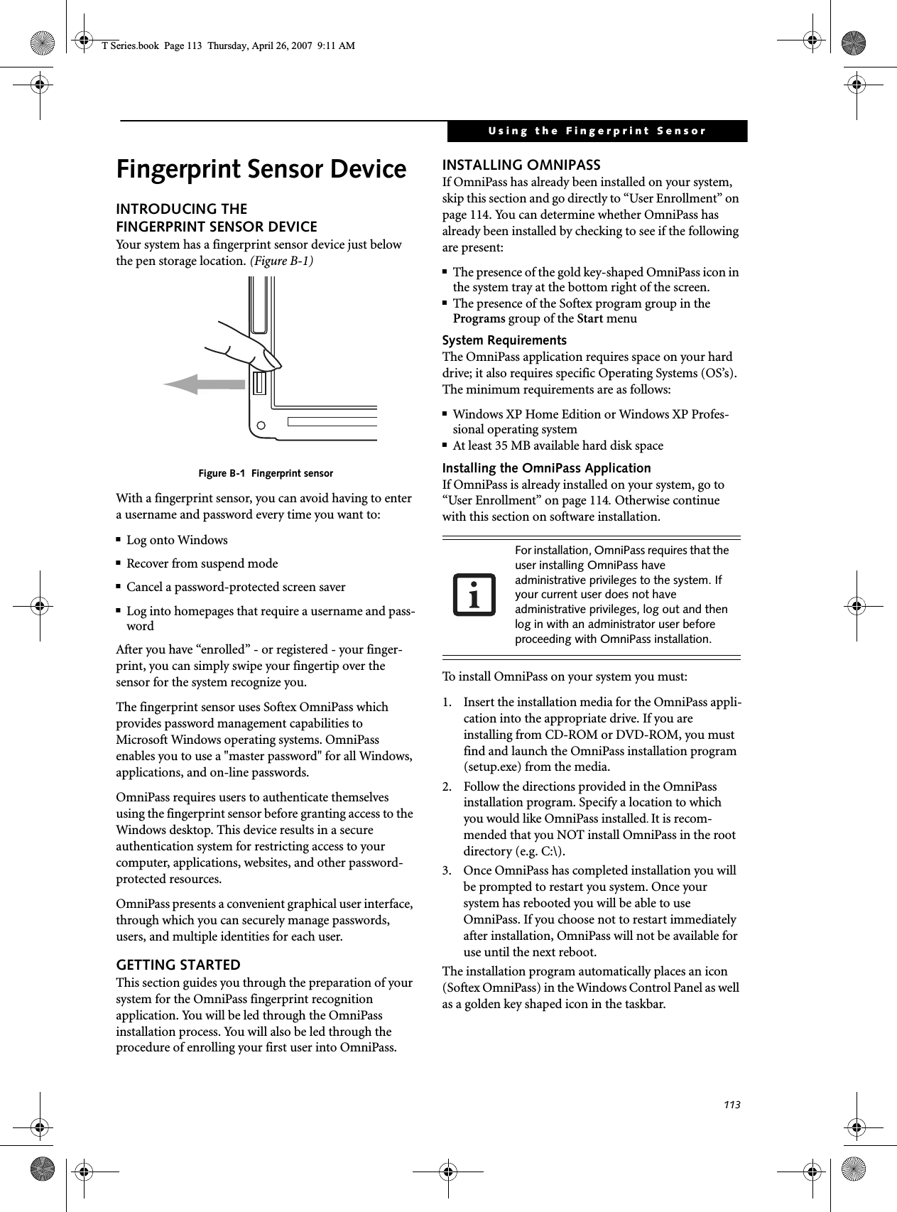
![114LifeBook T4200 Series Tablet PC – Appendix BVerifying Information about OmniPassAfter you have completed installing OmniPass and restarted your system, you may wish to check the version of OmniPass on your system.To check the version information of OmniPass:1. From the Windows Desktop, double-click the key-shaped OmniPass icon in the taskbar (usually located in the lower right corner of the screen),or,Click the Start button, select Settings, and click Control Panel (if you are using Windows XP you will see the Control Panel directly in the Start menu; click it, then click Switch to Classic View). Double-click Softex OmniPass in the Control Panel, and the OmniPass Control Center will appear. If it does not appear, then the program is not properly installed,or,Click the Start button, select Programs, and from the submenu select the Softex program group, from that submenu click OmniPass Control Center.2. Select the About tab at the top of the OmniPass Control Panel. The About tab window appears with version information about OmniPass.Uninstalling OmniPassTo remove the OmniPass application from your system:1. Click Start on the Windows taskbar. Select Settings, and then Control Panel.2. Double-click Add/Remove Programs.3. Select OmniPass, and then click Change/Remove.4. Follow the directions to uninstall the OmniPass application.5. Once OmniPass has finished uninstalling, reboot your system when prompted.USER ENROLLMENTBefore you can use any OmniPass features you must first enroll a user into OmniPass.Master Password ConceptComputer resources are often protected with passwords. Whether you are logging into your computer, accessing your email, e-banking, paying bills online, or accessing network resources, you often have to supply credentials to gain access. This can result in dozens of sets of creden-tials that you have to remember.During OmniPass user enrollment a "master password” is created for the enrolled user. This master password “replaces” all other passwords for sites you register with OmniPass. Example: A user, John, installs OmniPass on his system (his home computer) and enrolls an OmniPass user with username “John_01” and password “freq14”. He then goes to his webmail site to log onto his account. He inputs his webmail credentials as usual (username “John_02” and password “lifebook”), but instead of clicking [Submit], he directs OmniPass to Remember Password. Now whenever he returns to that site, OmniPass will prompt him to supply access credentials. John enters his OmniPass user credentials (“John_01” and “freq14”) in the OmniPass authentication prompt, and he is allowed into his webmail account. He can do this with as many websites or password protected resources he likes, and he will gain access to all those sites with his OmniPass user credentials (“John_01” and “freq14”). This is assuming he is accessing those sites with the system onto which he enrolled his OmniPass user. OmniPass does not actually change the credentials of the password protected resource. If John were to go to an Internet cafe to access his webmail, he would need to enter his original webmail credentials (“John_02” and “lifebook”) to gain access. If he attempts his OmniPass user credentials on a system other than where he enrolled that OmniPass user, he will not gain access.Basic EnrollmentThe Enrollment Wizard will guide you through the process of enrolling a user. Unless you specified other-wise, after OmniPass installation the Enrollment Wizard will launch on Windows login. If you do not see the Enrollment Wizard, you can bring it up by clicking Start on the Windows taskbar; select Programs; select Softex; click OmniPass Enrollment Wizard.1. Click Enroll to proceed to username and password verification. By default, the OmniPass Enrollment Wizard enters the credentials of the currently logged in Windows user.2. Enter the password you use to log in to Windows. This will become the “master password” for this OmniPass user. In most cases, the Domain: value For uninstallation, OmniPass requires that the user uninstalling OmniPass have administrative privileges to the system. If your current user does not have administrative privileges, log out and then log in with an administrator user before proceeding with OmniPass uninstallation. The enrollment procedure assumes you have no hardware authentication devices or alternate storage locations that you wish to integrate with OmniPass. If you desire such functionality, consult the appropriate sections of this document.T Series.book Page 114 Thursday, April 26, 2007 9:11 AM](https://usermanual.wiki/Fujitsu-Client-Computing/WB0047/User-Guide-790092-Page-123.png)
![115Using the Fingerprint Sensorwill be your Windows computer name. In a corpo-rate environment, or when accessing corporate resources, the Domain: may not be your Windows computer name. Click [Next] to continue.3. In this step OmniPass captures your fingerprint. Refer to “Enrolling a Fingerprint” on page 115 for additional information.4. Next, choose how OmniPass notifies you of various events. We recommend you keep Taskbar Tips on Beginner mode taskbar tips and Audio Tips on at least Prompt with system beeps only until you get accustomed to how OmniPass operates. Click [Next] to proceed with user enrollment. You will then see a Congratulations screen indicating your completion of user enrollment.5. Click [Done] to exit the OmniPass Enrollment Wizard. You will be asked if you’d like to log in to OmniPass with your newly enrolled user; click [Yes].Enrolling a FingerprintEnrolling a fingerprint will increase the security of your system and streamline the authentication procedure. You enroll fingerprints in the OmniPass Control Center. With an OmniPass user logged in, double-click the system tray OmniPass icon. Select the User Settings tab and click Enrollment under the User Settings area. Click Enroll Authentication Device and authenticate at the authentication prompt to start device enrollment.1. During initial user enrollment, you will be prompted to select the finger you wish to enroll. Fingers that have already been enrolled will be marked by a green check. The finger you select to enroll at this time will be marked by a red arrow. OmniPass will allow you re-enroll a finger. If you choose a finger that has already been enrolled and continue enrollment, OmniPass will enroll the fingerprint, overwriting the old fingerprint. Select a finger to enroll and click [Next].2. It is now time for OmniPass to capture your selected fingerprint. It may take a several capture attempts before OmniPass acquires your fingerprint. Should OmniPass fail to acquire your fingerprint, or if the capture screen times out, click [Back] to restart the fingerprint enrollment process. Your system has a “swipe” fingerprint sensor (See Figure B-1). A swipe sensor is small and resembles a skinny elongated rectangle. To capture a fingerprint, gently swipe or pull your fingertip over the sensor (starting at the second knuckle) towards yourself. Swiping too fast or too slow will result in a failed capture. The Choose Finger screen has a [Practice] button; click it to practice capturing your finger-print. When you are comfortable with how your fingerprint is captured, proceed to enroll a finger.3. Once OmniPass has successfully acquired the finger-print, the Ver i f y Fin ge rp r in t screen will automati-cally appear. To verify your enrolled fingerprint, swipe your fingertip over the sensor four times to verify. Successful fingerprint verification will show a green fingerprint in the capture window and the text Verification Successful under the capture window. (An unsuccessful swipe will be indicated in red.)USING OMNIPASSYou are now ready to begin using OmniPass. Used regu-larly, OmniPass will streamline your authentications.Password ReplacementYou will often use the password replacement function. When you go to a restricted access website (e.g., your bank, your web-based email, online auction or payment sites), you are always prompted to enter your login credentials. OmniPass can detect these prompts and you can teach OmniPass your login credentials. The next time you go to that website, you can authenticate with your fingerprint to gain access.OmniPass Authentication ToolbarAfter installing OmniPass and restarting, you will notice a dialog you have not seen before at Windows Logon. This is the OmniPass Authentication Toolbar, and it is displayed whenever the OmniPass authentication system is invoked. The OmniPass authentication system may be invoked frequently: during Windows Logon, during OmniPass Logon, when unlocking your workstation, when resuming from standby or hibernate, when unlocking a password-enabled screensaver, during pass-word replacement for remembered site or application logins, and more. When you see this toolbar, OmniPass is prompting you to authenticate.The Logon Authentication window indicates what OmniPass-restricted function you are attempting. The icons in the lower left (fingerprint and key) show what authentication methods are available to you. Selected authentication methods are highlighted while unselected methods are not. When you click the icon for an unse-lected authentication method, the authentication prompt associated with that method is displayed.When prompted to authenticate, you must supply the appropriate credentials: an enrolled finger for the finger-print capture window or your master password for the master password prompt (the key icon).Remembering a PasswordOmniPass can remember any application, GUI, or pass-word protected resource that has a password prompt.Using the following procedure, you can store a set of credentials into OmniPass. These credentials will then be linked to your “master password” or fingerprint.T Series.book Page 115 Thursday, April 26, 2007 9:11 AM](https://usermanual.wiki/Fujitsu-Client-Computing/WB0047/User-Guide-790092-Page-124.png)
![116LifeBook T4200 Series Tablet PC – Appendix BGo to a site that requires a login (username and pass-word), but do not log in yet. At the site login prompt, enter your username and password in the prompted fields, but do not enter the site (do not hit [Enter], [Submit], [OK], or Login). Right-click the OmniPass system tray icon and select Remember Password from the submenu. The Windows arrow cursor will change to a golden key OmniPass cursor. Click this OmniPass cursor in the login prompt area, but do not click the [Login] or [Submit] button.Associating a Friendly NameAfter clicking the OmniPass key cursor near the login prompt, OmniPass will prompt you to enter a “friendly name” for this site. You should enter something that reminds you of the website, the company, or the service you are logging into. In its secure database, OmniPass associates this friendly name with this website.Additional Settings for Remembering a SiteWhen OmniPass prompts you to enter a “friendly name” you also have the opportunity to set how OmniPass authenticates you to this site. There are three effective settings for how OmniPass handles a remembered site.The default setting is Automatically click the “OK” or “Submit” button for this password protected site once the user is authenticated. With this setting, each time you navigate to this site OmniPass will prompt you for your master password or fingerprint authentication device. Once you have authenticated with OmniPass, you will automatically be logged into the site. Less secure is the option to Automatically enter this password protected site when it is activated. Do not prompt for authentication. Check the upper box to get this setting, and each time you navigate to this site OmniPass will log you into the site without prompting you to authenticate.If you uncheck both boxes in Settings for this Password Site, OmniPass will prompt you for your master pass-word or fingerprint authentication device. Once you have authenticated with OmniPass your credentials will be filled in to the site login prompt, but you will have to click the website [OK], [Submit], or [Login] button to gain access to the site. Click Finish to complete the remember password proce-dure. The site location, the credentials to access the site, and the OmniPass authentication settings for the site are now stored in the OmniPass secure database. The OmniPass authentication settings (Settings for this Pass-word Site) can always be changed in Vault Management.Logging in to a Remembered SiteWhether or not OmniPass prompts you to authenticate when you return to a remembered site is determined by Settings for this Password Site and can be changed in Vault Management. The following cases are applicable to using OmniPass to login to: Windows, remembered websites, and all other password protected resources.With Master PasswordOnce you return to a site you have remembered with OmniPass, you may be presented with a master pass-word prompt. Enter your master password and you will be allowed into the site.Logging into Windows with a Fingerprint DeviceWhen logging into Windows with a fingerprint device, the fingerprint capture window will now appear next to the Windows Login screen. Place your enrolled fingertip on the sensor to authenticate. You will be simultaneously logged into Windows and OmniPass. The capture window will also appear if you have used Ctrl-Alt-Del to lock a system, and the fingerprint device can be used to log back in as stated above.In Windows XP, your login options must be set either for classic login, or for fast user switching and logon screen to be enabled to use your fingerprint to log on to Windows. To change this go to Control Panel, select User Accounts and then click Change the way users log on or off. If your Windows screensaver is password protected, the fingerprint capture window will now appear next to screensaver password dialog during resume. You can authenticate to your screensaver pass-word prompt with your enrolled finger.Password ManagementOmniPass provides an interface that lets you manage your passwords. To access this GUI, double-click the OmniPass key in the system tray. Click Vaul t Man age -ment; you will be prompted to authenticate. Once you gain access to Vault Management, click Manage Pass-words under Vault Settings. You will see the Manage Passwords interface, with a list of friendly names.This setting is more convenient in that whenever you go to a site remembered with this setting, you will bypass any authentication procedure and gain instant access to the site. But should you leave your system unattended with your OmniPass user logged in, anyone using your system can browse to your password protected sites and gain automatic access.If a machine is locked and OmniPass detects a different user logging back in with a fingerprint, the first user will be logged out and the second user logged in.T Series.book Page 116 Thursday, April 26, 2007 9:11 AM](https://usermanual.wiki/Fujitsu-Client-Computing/WB0047/User-Guide-790092-Page-125.png)
![117Using the Fingerprint SensorYou can view the credentials stored for any remembered website by highlighting the desired resource under Pass-word Protected Dialog and clicking Unmask Values. Should a password be reset, or an account expire, you can remove stored credentials from OmniPass. Highlight the desired resource under Password Protected Dialog and click Delete Page. You will be prompted to confirm the password deletion.The two check boxes in Manage Passwords govern whether OmniPass prompts you to authenticate or directly logs you into the remembered site.OmniPass will overwrite an old set of credentials for a website if you attempt to use Remember Password on an already remembered site. The exception to the above rule is the resetting of your Windows password. If your password is reset in Windows, then the next time you login to Windows, OmniPass will detect the password change and prompt you to “Update” or “Reconfirm” your password with OmniPass. Enter your new Windows password in the prompt(s) and click OK and your OmniPass "master password" will still be your Windows password.OmniPass User IdentitiesIdentities allow OmniPass users to have multiple accounts to the same site (e.g., bob@biblomail.com and boballen@biblomail.com). If OmniPass did not provide you identities, you would be limited to remembering one account per site.To create and manage identities, double-click the OmniPass key in the system tray. Click Vault Man age -ment; OmniPass will prompt you to authenticate. Once you gain access to Vault Management, click Manage Identities under Vault Settings. You can only manage the identities of the currently logged in OmniPass userTo add a new identity, click New Identity or double-click Click here to add a new identity. Name the new identity and click [OK], then click [Apply]. You can now switch to the new identity and start remembering passwords.To delete an identity, highlight the identity you want to delete and click [Delete Identity], then click [Apply].To set the default identity, highlight the identity you want as default and click [Set as Default]; click [Apply] to ensure the settings are saved. If you log in to OmniPass with a fingerprint device, you will automati-cally be logged in to the default identity for that OmniPass user. You can choose the identity with which you are logging in if you login using "master password".Choosing User Identity during LoginTo choose your identity during login, type your user-name in the User Name: field. Press [Tab] and see that the Domain: field self-populates. Click the Password: field to bring the cursor to it, and you will see the pull-down menu in the Identity: field. Select the identity you wish to login as and then click OK to login.Switch User IdentityTo switch identities at any time, right-click the OmniPass system tray icon and click Switch User Iden-tity from the submenu. The Switch Identity dialog will appear. Select the desired identity and then click OK.Identities and Password ManagementOn the Manage Passwords interface of the Va u l t Management tab of the OmniPass Control Center, there is a pull-down selection box labeled, Identity. This field lets you choose which identity you are managing pass-words for. When you select an identity here, only those password protected dialogs that are associated with that identity are shown. You can perform all the functions explained in “Password Management” on page 116.CONFIGURING OMNIPASSThis section gives an overview of both the Export/Import function and the OmniPass Control Center. Exporting and Importing UsersUsing the OmniPass Control Center, you can export and import users in and out of OmniPass. The export process backs up all remembered sites, credentials, and any enrolled fingerprints for an OmniPass user. All OmniPass data for a user is backed up to a single encrypted database file. During the import process, the Windows login of the exported user is required. If the proper credentials cannot be supplied, the user profile will not be imported. When you delete an identity, all of its associated remembered sites and password protected dialogs are lost.■You should periodically export your user profile and store it in a safe place. If anything happens to your system, you can import your OmniPass profile to a new system and have all your remem-bered settings and fingerprints instantly.■You don't forget the Windows login credentials when exporting. When you examine the importation, you are prompted for authentication. The credentials that will allow a user profile to be imported are the Windows login credentials of the exported user. They are the credentials that had to be submitted when the user profile was exported. You will need User Name, Password, and Domain.T Series.book Page 117 Thursday, April 26, 2007 9:11 AM](https://usermanual.wiki/Fujitsu-Client-Computing/WB0047/User-Guide-790092-Page-126.png)