Fujitsu Client Computing WL0004 Stylistic ST Series Pentablet PC & WLAN (Atheros) User Manual Appendix P User Manual
Fujitsu Limited Stylistic ST Series Pentablet PC & WLAN (Atheros) Appendix P User Manual
Contents
- 1. User Manual
- 2. Users Manual
User Manual
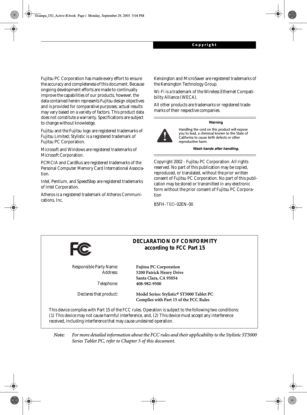


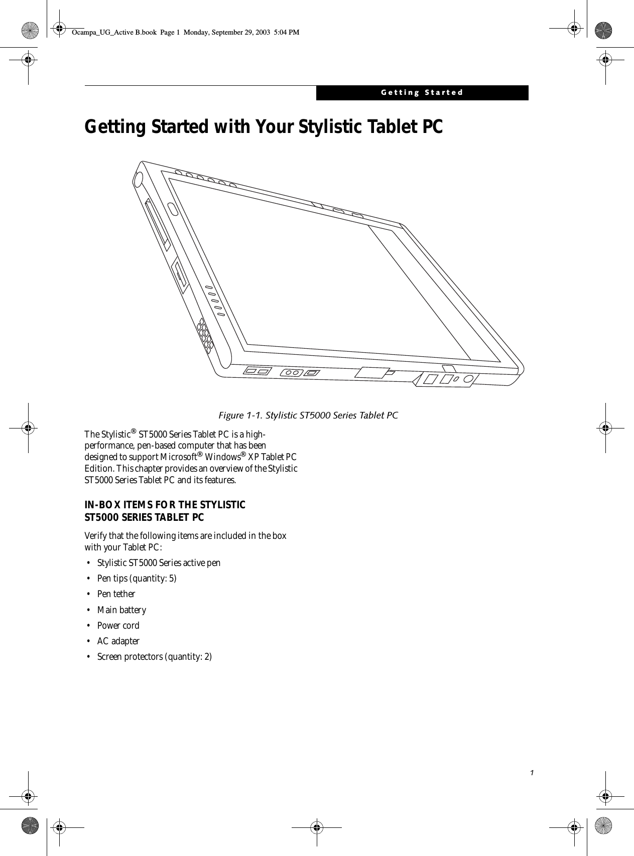
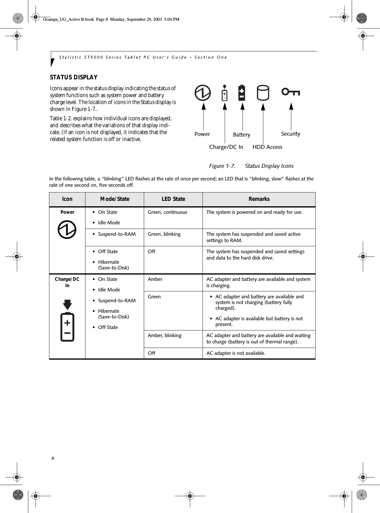
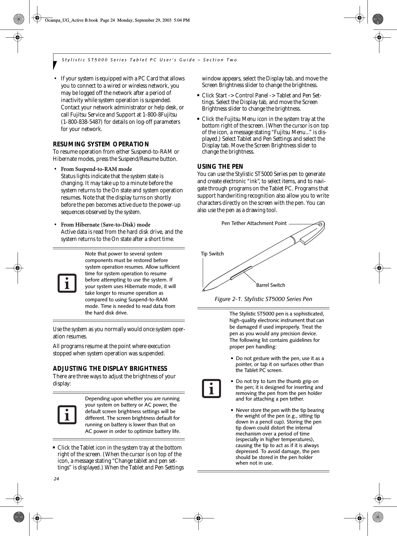
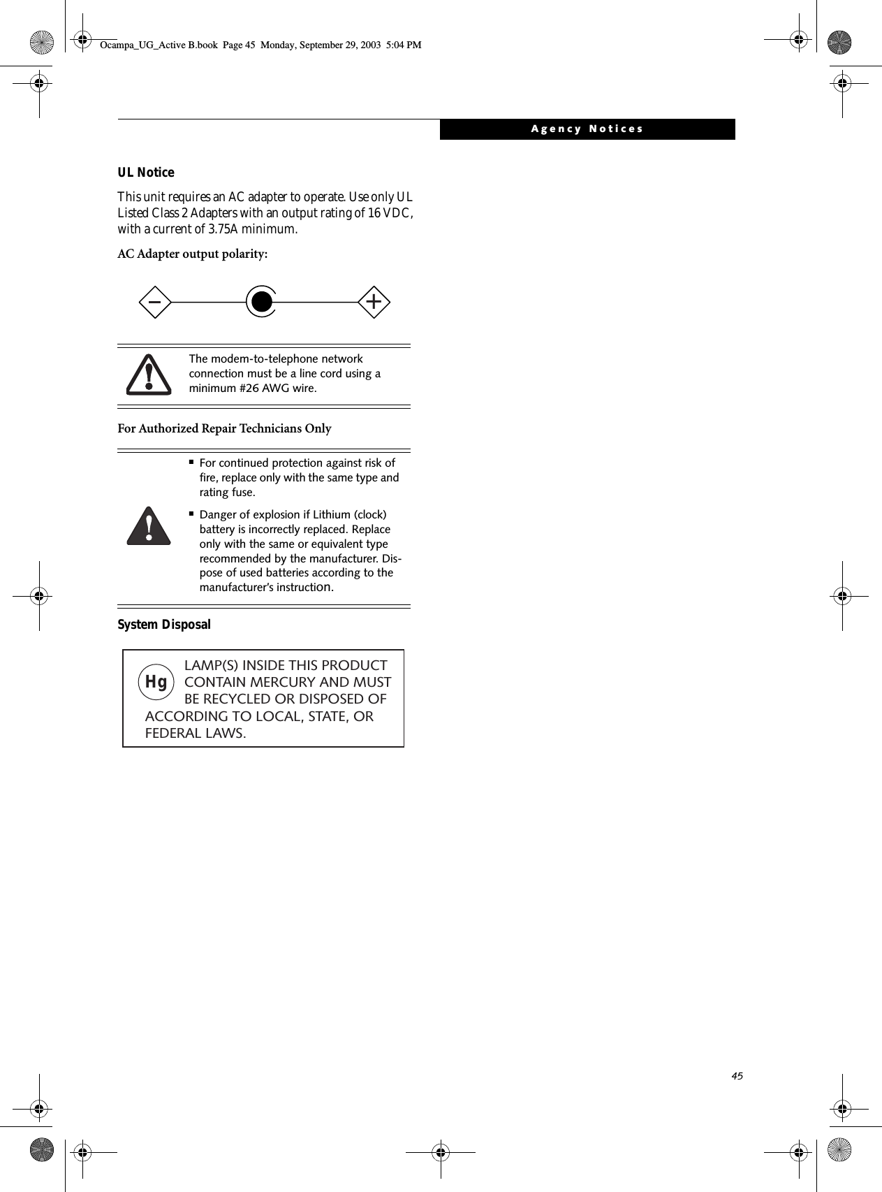
![PrefacePrefaceABOUT THIS GUIDEThe Stylistic ST5000 Series Tablet PC is a high-performance, pen-based computer that has been designed to support MicrosoftWindows XP Tablet PC Edition.This manual explains how to operate your Fujitsu Stylistic ST5000 Series Tablet PC’s hardware and built-in system software. The Stylistic ST5000 Series Tablet PC is a completely self-contained unit with an active-matrix (TFT) color LCD display and an active digitizer. It has a powerful interface that enables it to support a variety of optional features. Conventions Used in the GuideKeyboard keys appear in brackets. Example: [Fn], [F1], [ESC], [ENTER] and [CTRL].Pages with additional information about a specific topic are cross-referenced within the text.Example: (See page xx.)On screen buttons or menu items appear in boldExample: Click OK to restart your Tablet PC.DOS commands you enter appear in Courier type. Example: Shut down the computer?FUJITSU CONTACT INFORMATIONService and SupportYou can contact Fujitsu Service and Support in the following ways:■Toll free: 1-800-8Fujitsu (1-800-838-5487)■Fax: 408-764-2724 ■E-mail: 8fujitsu@fujitsupc.com ■Web site: http://www.fujitsupc.comBefore you place the call, you should have the following information ready so the customer support representative can provide you with the fastest possible solution:■Product name■Product configuration number■Product serial number■Purchase date■Conditions under which the problem occurred■Any error messages that have occurred■Hardware configuration■Type of device connected, if anyFujitsu OnlineYou can go directly to the online Fujitsu product catalog for your Tablet PC by going to the Fujitsu Web site at: http://www.fujitsupc.comWARRANTY INFORMATIONYour Stylistic ST5000 Series Tablet PC is backed an Inter-national Limited Warranty. Check the service kit that came with your system for warranty terms and condi-tions.The information icon highlights information that will enhance your understanding of the subject material.The caution icon highlights information that is important to the safe operation of your computer, or to the integrity of your files. Please read all caution information carefully.The warning icon highlights information that can be hazardous to either you, your computer, or your files. Please read all warning information carefully.You must have an active internet connec-tion to use the online URL links.Ocampa_UG_Active B.book Page v Monday, September 29, 2003 5:04 PM](https://usermanual.wiki/Fujitsu-Client-Computing/WL0004.User-Manual/User-Guide-382909-Page-8.png)


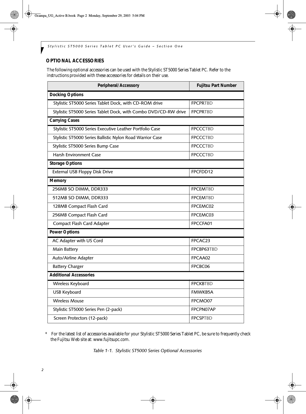
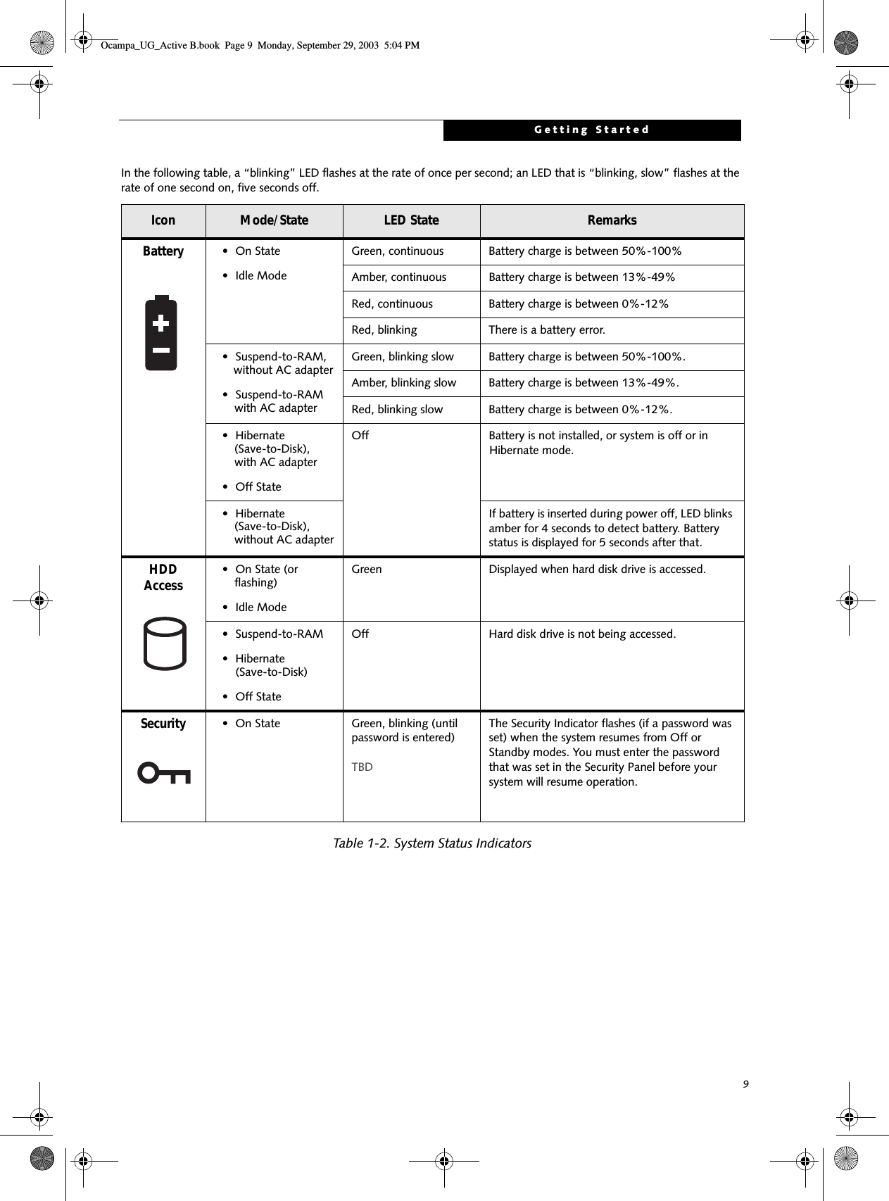
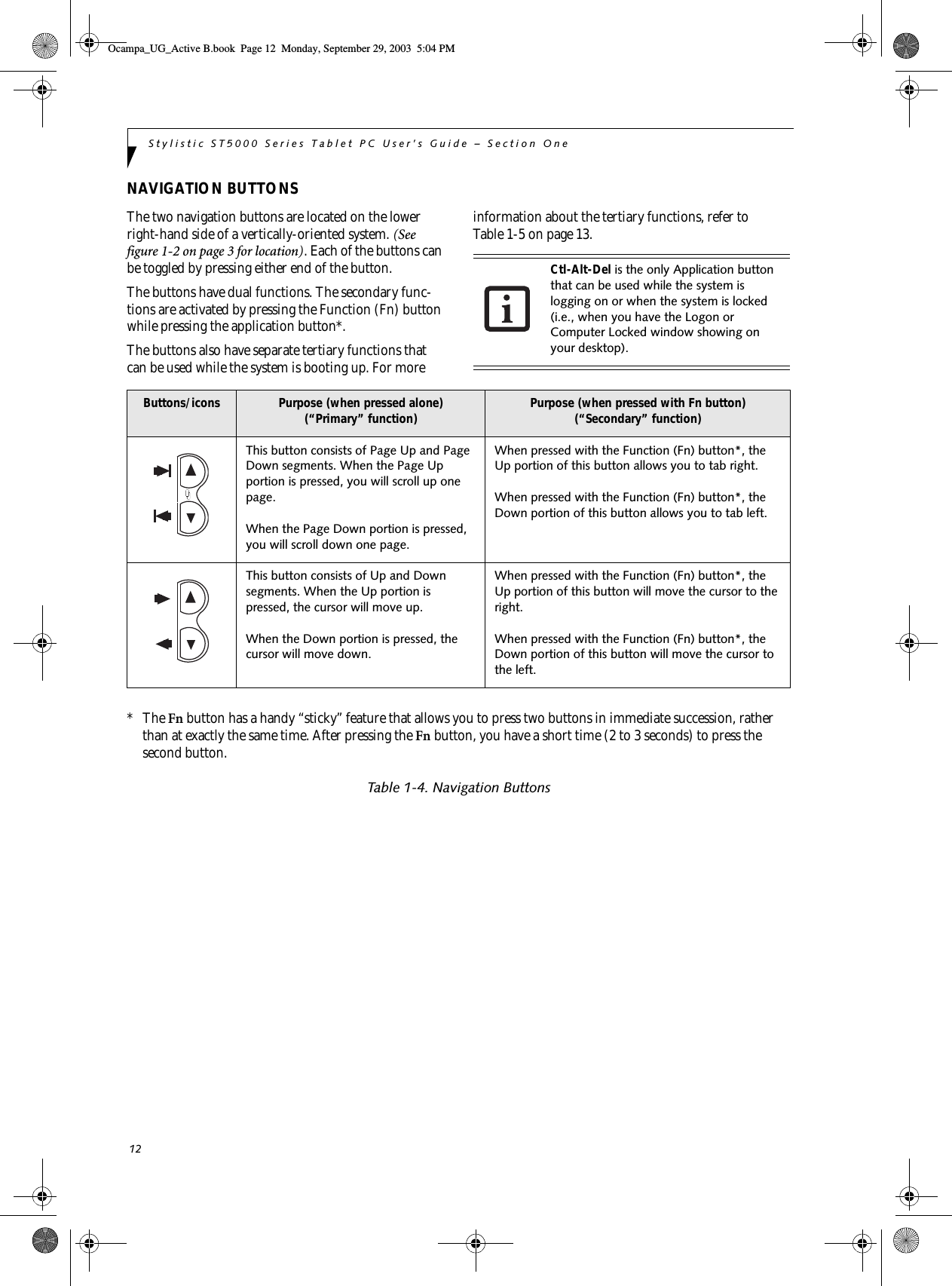
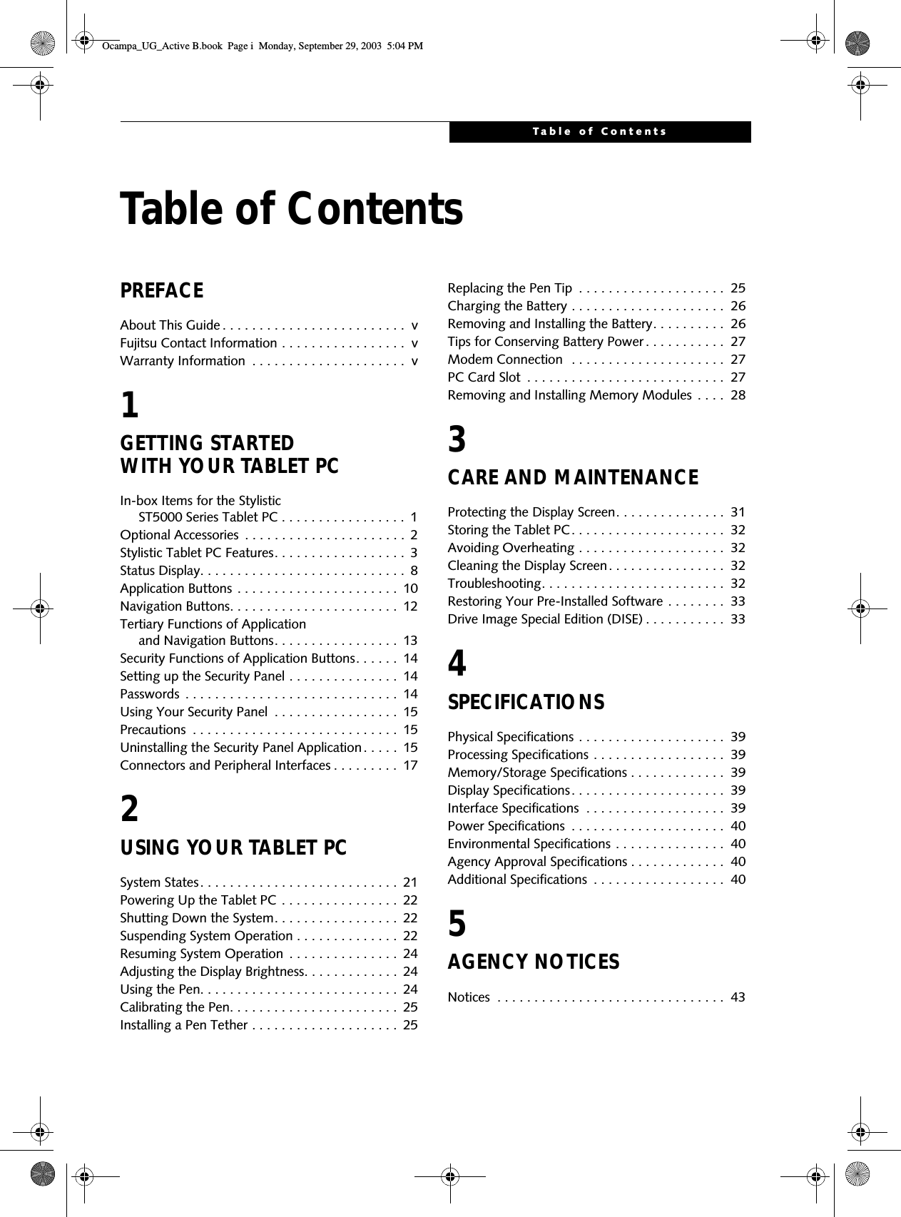
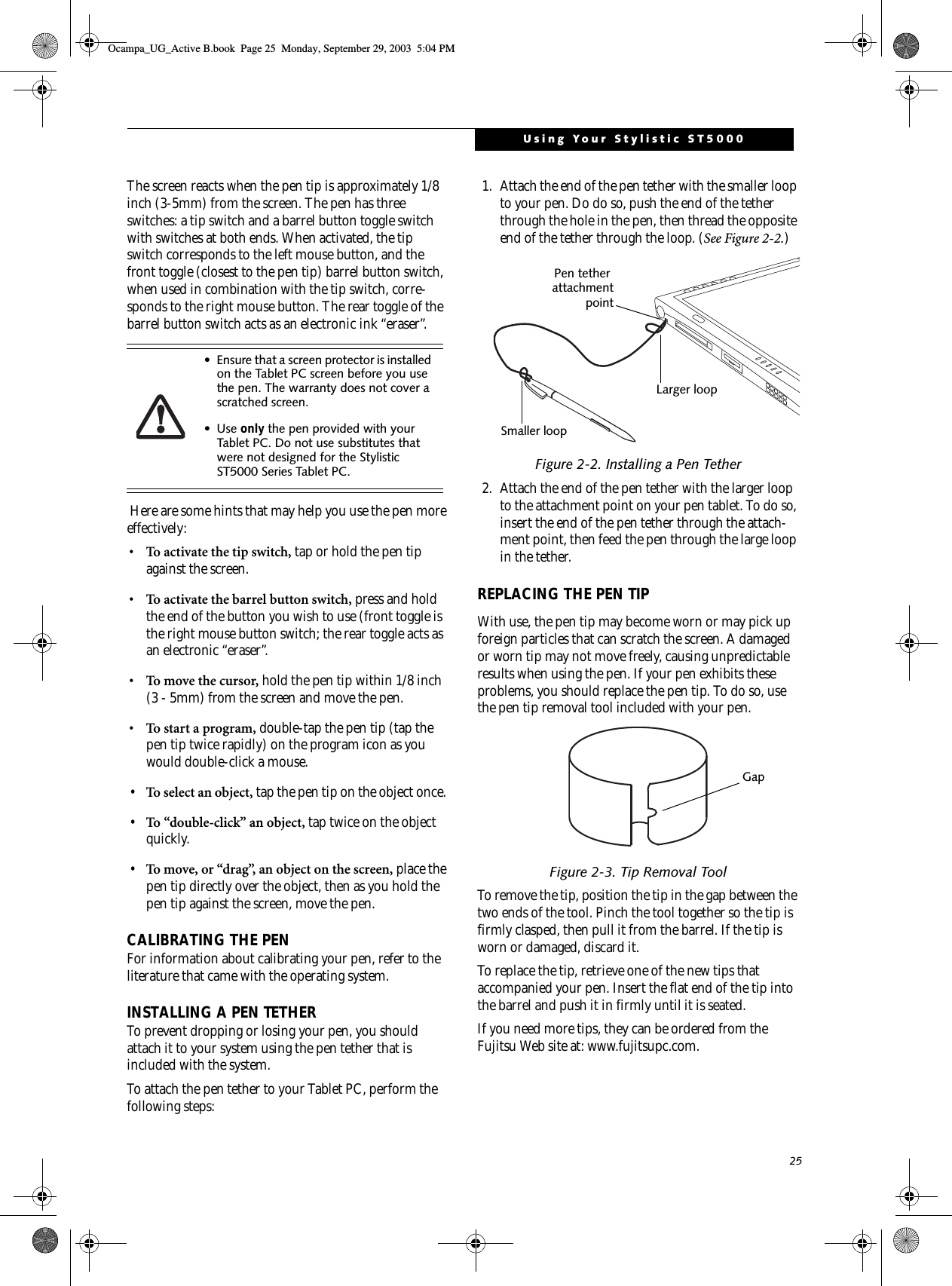
![13Getting StartedTERTIARY FUNCTIONS OF APPLICATION AND NAVIGATION BUTTONSWhile you are booting up your system, the Application Buttons and Navigation buttons can be used for entering and navigating through the Basic Input-Output System (BIOS), and for invoking the Advanced Options Menu, where you can enter different modes (such as Safe Mode).The BIOS is a program and a set of parameters that are stored in ROM, which tests and operates your Tablet PC from when you turn it on until it loads your installed operating system from disk. Information from the BIOS is transferred to the operating system to provide it with information on the configuration and status of the hard-ware.The system is booting up while the Fujitsu logo is displayed immediately after turning on the system. The table below indicates how the buttons act while the system is booting up and while you are in the BIOS.Table 1-5. Tertiary Functions of Application and Navigation ButtonsButtons/icons Purpose (when pressed while the system is booting up)Ctl-Alt-Del ButtonPressing the Ctl-Alt-Del button while the system is booting up takes you into BIOS setup. This is the same as if you had tapped [F2] on a keyboard.EMail ButtonPressing the EMail button while the system is booting up opens the Boot Options menu. This is the same as if you had tapped [F12] on a keyboard.Orientation ButtonPressing the Orientation button while the BIOS setup screen is open causes the selected item (if applicable) to change to the next item. Pressing this is the same as tapping the spacebar on a keyboard.Escape ButtonPressing the Esc button while the BIOS is open acts to escape from the BIOS. This is the same as if you had tapped [Esc] on a keyboard.Enter ButtonPressing the Ent button while the BIOS is open acts the same as the [Ent] button on a keyboard. Function ButtonPressing the Fn button while the system is displaying the operating system boot menu, opens the Advanced Operating System Options menu. This menu allows you to enter different operating system modes (such as Safe Mode). Pressing this button is the same as if you had tapped [F8] on a keyboard.Pressing the top half of the upper navigation button while the BIOS setup screen is open causes the cursor in the BIOS setup screen to move up. This is the same as if you had tapped Arrow Up on a keyboard. This feature is also functional in the operating system boot menu.Pressing the bottom half of the upper navigation button while the BIOS setup screen is open causes the cursor in the BIOS setup screen to move down. This is the same as if you had tapped Arrow Down on a keyboard. This feature is also functional in the operating system boot menu.Pressing the top half of the lower navigation button while the BIOS setup screen is open causes the cursor in the BIOS setup screen to move right. This is the same as if you had tapped Arrow Right on a keyboard.Pressing the bottom half of the lower navigation button while the BIOS setup screen is open causes the cursor in the BIOS setup screen to move left. This is the same as if you had tapped Arrow Left on a keyboard.Ocampa_UG_Active B.book Page 13 Monday, September 29, 2003 5:04 PM](https://usermanual.wiki/Fujitsu-Client-Computing/WL0004.User-Manual/User-Guide-382909-Page-24.png)
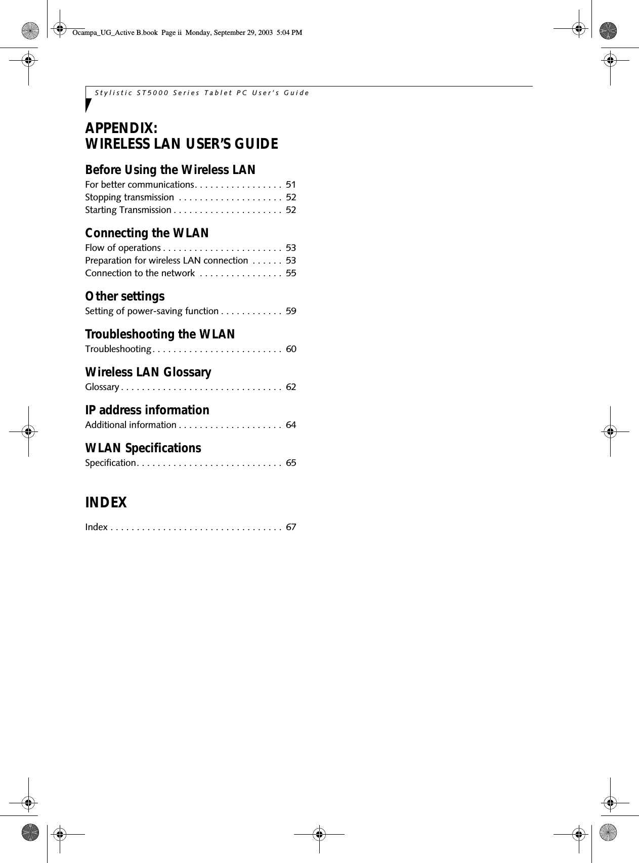
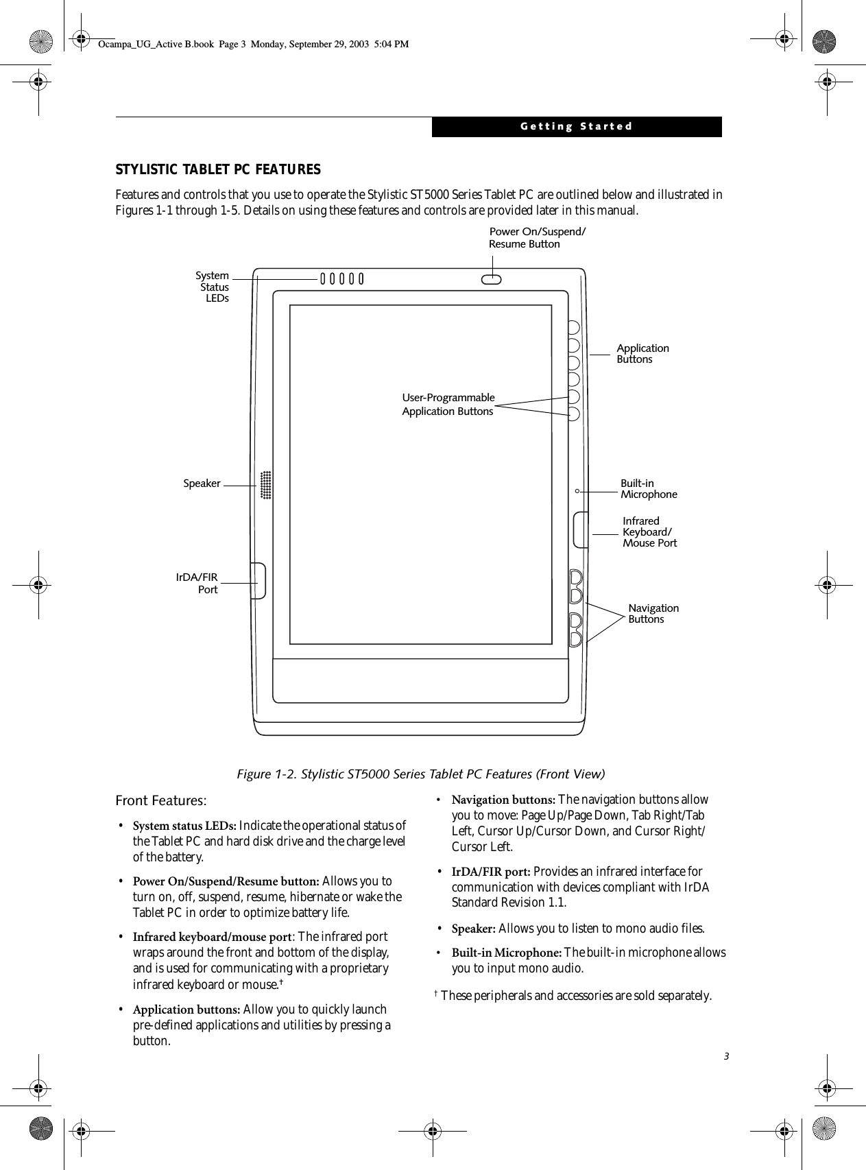
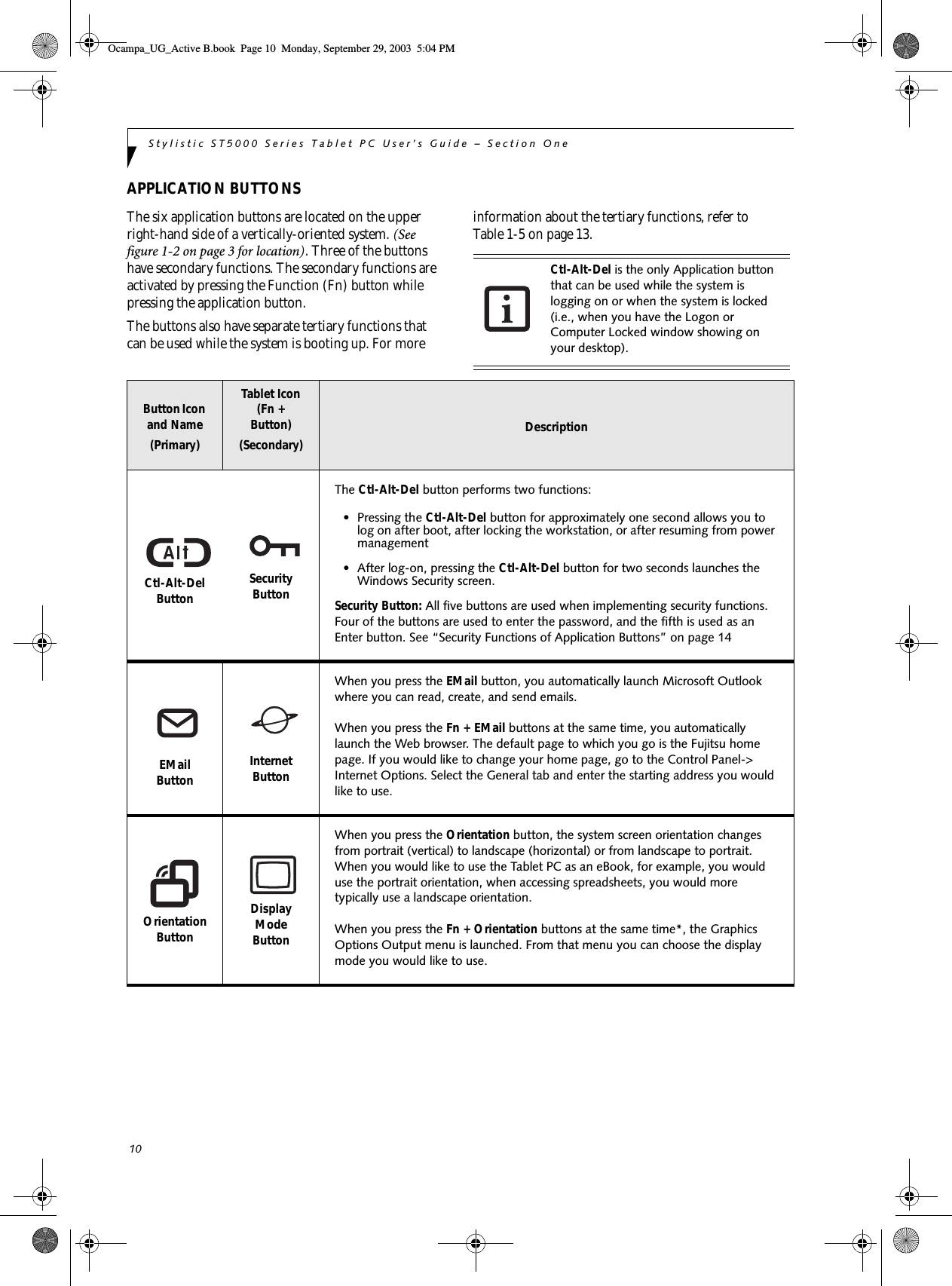
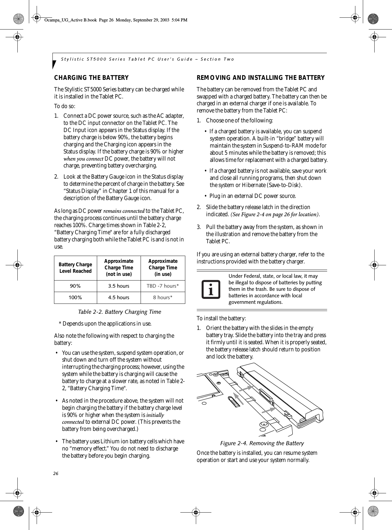
![14Stylistic ST5000 Series Tablet PC User’s Guide – Section OneSECURITY FUNCTIONS OF APPLICATION BUTTONSFive buttons are used when implementing security functions. Four of the buttons are used to enter the password, and the fifth is used as an Enter button. Instructions for using the security feature follow the table.Table 1-6. Security Functions of Application ButtonsSETTING UP THE SECURITY PANELWhen you receive your Tablet PC, the security panel application is pre-installed without any passwords. The following sections provide detailed information on your security panel, how to set, change or remove passwords.Numbered ButtonsUse these buttons to enter your password.(Figure 1-6)Enter ButtonAfter entering the button strokes, push this button to enter the password into the Tablet PC. (Figure 1-6)PASSWORDSThe user and supervisor password may be set on this Tablet PC. A supervisor password is typically the same for all Tablet PC’s and notebooks in a work group, office, or company to allow for system management. Individual computers in a group environment should not use a common password. A password consists of one to five button strokes plus the enter button. A valid stroke consists of pushing one or up to four buttons simulta-neously. The following are valid button strokes: ■Pushing [4] by itself■Pushing [2] and [3] at the same time■Pushing [1], [2], and [4] at the same time■Pushing [1], [2], [3], and [4] at the same timeThe following are valid passwords. The numbers within braces ({ }) are button strokes using more than one button. ■{[2]+[3]}, [1], [Enter]■[4], [enter]■{[1]+[3]}, {[2]+[3]+[4]}, [1], [4], [2], [Enter]Setting PasswordsWhen shipped from the factory, no passwords are set. You have a choice of having no password or setting a supervisor and user password. You must set the super-visor password before the user password. Button Icons Security Icons Security PurposeCtl-Alt-Del Button Security Enter ButtonEMail Button 1Security Button 1Orientation Button2Security Button 2Escape Button 3Security Button 3Enter Button 4Security Button 4■The purpose of supervisor password is to be able to bypass the user password in case the user password is forgotten. The supervisor password alone will not lock the system.■You must set the supervisor and user passwords for the security panel to work.Ocampa_UG_Active B.book Page 14 Monday, September 29, 2003 5:04 PM](https://usermanual.wiki/Fujitsu-Client-Computing/WL0004.User-Manual/User-Guide-382909-Page-25.png)
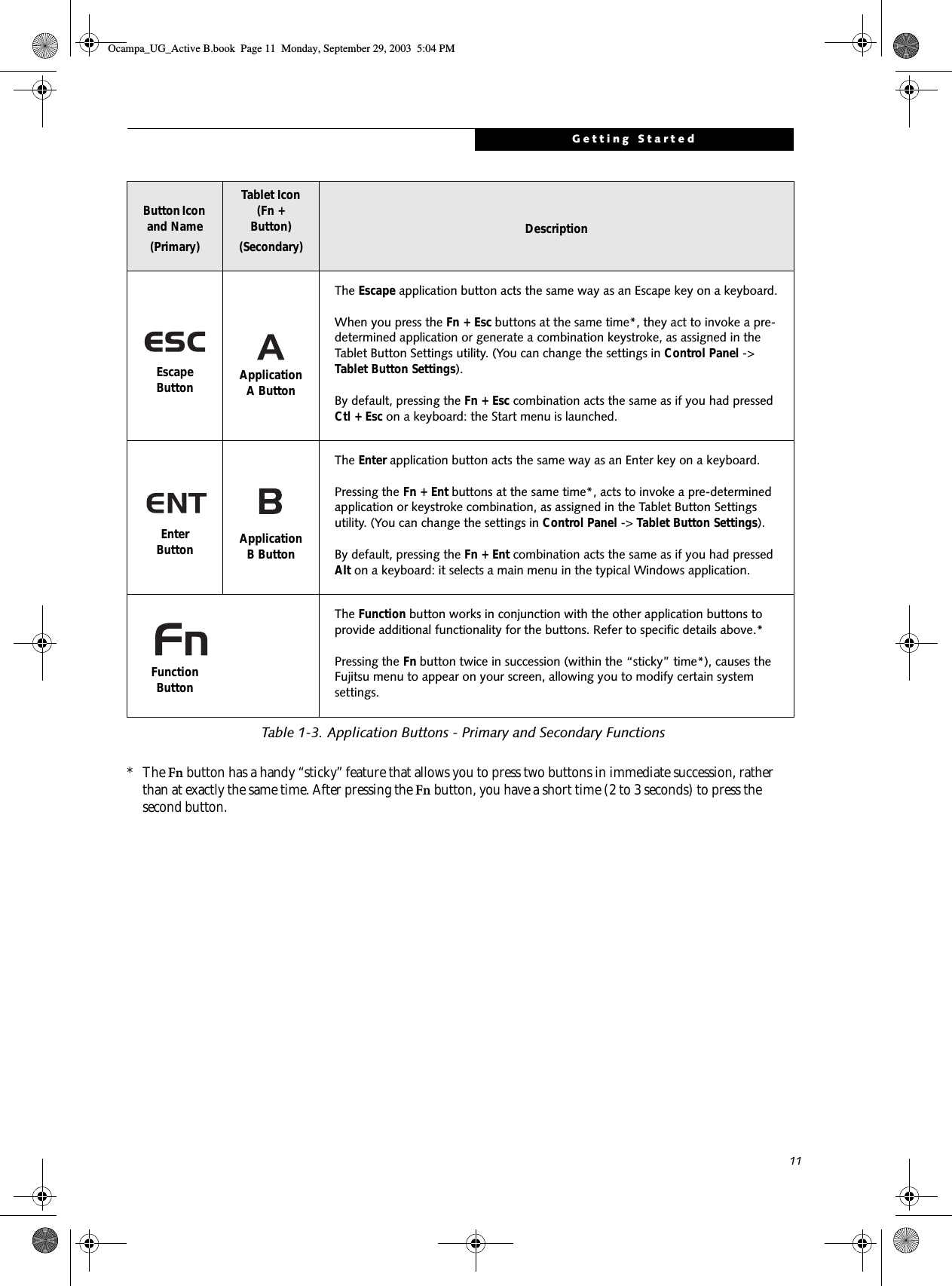
![15Getting StartedSetting Supervisor PasswordYou must have set a supervisor password before setting any user passwords. The supervisor password can bypass the user password.1. Go to the Start menu.2. Click on Run.3. Type in:C:\Program Files\Fujitsu\Security Panel Application\Supervisor\ FJSECS.EXE, then press [Enter]4. Follow the on-screen instructions to set theSupervisor password.Setting User Password1 Go to the Start menu.2. Click on All Programs.3. Click on Security Panel Application -> Security Panel Application.4. Follow the on-screen instructions to set theuser password.USING YOUR SECURITY PANELThe security lock feature is in effect both when the system resumes from Off, Standby, or Hibernation state. You always need to push the Security Panel buttons to input the user password. Your system will not begin the boot sequence until you enter your supervisor/user password.From Off State1. Turn on your system.2. When the Security Indicator flashes, enter the pass-word and press Enter button.For example, if the password is 22222, first press Button 2 five times and press the Enter button. The Tablet PC will boot to normal operation.From Standby/Hibernation State1. Press your Suspend/Resume button.2. When the Security Indicator flashes, enter the pass-word and press Enter button.The Tablet PC should resume normal operation.Incorrect Password EntryIf an invalid supervisor or user password is entered three times in succession, the system will “beep” for about one minute. If a valid password is entered within a minute (while system beeps), the beeping will stop and the Tablet PC will resume normal operation. If no password is entered or an invalid password is entered while the system beeps, the system will return to its previous locked state (standby or off) and the Security Indicator will go off. To reactivate the Tablet PC after a password failure, you must press the Suspend/Resume button, then enter a correct password.PRECAUTIONSOpening and Closing the CoverBy default, closing the cover automatically places your system into Standby mode. (You can change the action the system takes when the cover is closed by opening the Power Options Properties icon in the Control Panel, and selecting the Advanced tab. Make a choice from the drop down menu for “When I close the lid of my portable computer:” and click the [OK] button.) Opening the cover does not automatically place the Tablet PC into normal operation. Instead, you must enter the proper security password after pushing the Suspend/Resume button.Low Battery OperationsIf your Tablet PC has a low battery, pushing the suspend/resume button only turns on the Security Indicator. Your Tablet PC does not unlock, the Security Indicator turns off after one minute. To resume normal operation, first attach a power supply to the Tablet PC. Then you may unlock the Tablet PC.UNINSTALLING THE SECURITY PANEL APPLICATIONYou have two options when uninstalling the securitypanel application:■Remove passwords and uninstall the security panel application software. This will disable all security features.■Uninstall the security panel application with password still active. This will not allow any changes to the password. Uninstalling the Security Panel Application SoftwareRemove passwords when User wants no password protec-tion whatsoever and doesn’t want to give anybody the utility to set a password on their computer. In this case, if passwords (supervisor, user, or both) are set, the pass-words must first be cleared BEFORE removing the appli-You may change or remove the supervisor or user password by repeating the steps defined above.Remember the user password you specified on the Security Panel Application. If you forget the password you will not be able to use your computer. The supervisor pass-word can override the user password.Ocampa_UG_Active B.book Page 15 Monday, September 29, 2003 5:04 PM](https://usermanual.wiki/Fujitsu-Client-Computing/WL0004.User-Manual/User-Guide-382909-Page-26.png)

![27Using Your Stylistic ST5000TIPS FOR CONSERVING BATTERY POWERYou can extend the charge life of your battery by conserving battery power. (Your results may vary depending on your application and how the system is configured.) Here are some suggestions to help you conserve battery power:• Use an external power source such as the AC adapter whenever the system is docked. • Suspend system operation if you know that you won’t be using the system for a while. • Shut down the system if you won’t be using the system for an extended period of time. • Use power management (available on the desktop) to help you conserve power automatically. • Battery life is dependent upon the operating system, power settings, and applications in use.Operation of the Bridge Battery When installed in the Tablet PC, the battery provides power to some system components—even when the system is in the Off state. When the battery is removed, power is supplied to these components by a “bridge” battery that is built into the Tablet PC.The bridge battery is not designed for long-term opera-tion. To maintain the bridge battery properly, observe the following measures:• To prevent draining the bridge battery, always store the system with a charged battery installed. • If the bridge battery becomes drained, it takes approximately 8 hours for it to be fully recharged.• The bridge battery charges when the AC Adapter is connected and the system is in On or Off states or Suspend mode. It charges from the battery only when the system is in the On state.MODEM CONNECTION The Stylistic ST5000 Series Tablet PC is designed to accept a standard RJ-11 telephone plug. Connect the plug to the modem jack located on the left-hand side of the Tablet PC (See Figure 1-4 on page 5 for location). The tele-phone plug can be installed whether or not the Tablet PC has power applied.If you need assistance configuring the Stylistic ST5000 Series Tablet PC modem or LAN, contact your local help desk or reseller.PC CARD SLOTThe Stylistic ST5000 Series Tablet PC Card slot allows you to install a Type I or Type II PCMCIA Card. Installing a PC CardTo install a PC card, position the side with the arrow facing up (i.e., when looking at the tablet’s display side, the arrow on the card should be visible.) Slide the card into the PC Card slot, and press it firmly to ensure proper seating. (See Figure 2-5 for location)If you need assistance installing a PC Card in the Stylistic ST5000 Series Tablet PC, contact your corporate help desk or reseller.Figure 2-5. Installing a PC CardRemoving a PC CardTo remove a PC Card, first click the Safely Remove Hard-ware icon in the system tray in the bottom right-hand corner of the display. Select PC Card from the list, and click [Stop]. Press the PC Card eject button so that it pops out. Once the button has popped out, press it firmly to eject the card. (See Figure 2-6 for location)• The bridge battery function is disabled if Wake On LAN is enabled in the BIOS.• The system arrives with the bridge battery in a discharged state. Be sure to charge it sufficiently before relying upon it to support the system in the event of battery removal. The internal 56 Kbps LAN/modem module installed in the Stylistic ST5000 Series Tablet PC has actual maximum transfer rates of 53 Kbps (receive), 33.6 Kbps (send), and 14.4 Kbps (fax). Download rates are limited to 53 Kbps in the United States due to FCC restrictions.Ocampa_UG_Active B.book Page 27 Monday, September 29, 2003 5:04 PM](https://usermanual.wiki/Fujitsu-Client-Computing/WL0004.User-Manual/User-Guide-382909-Page-38.png)

![34Stylistic ST5000 Series Tablet PC User’s Guide – Section ThreeCreating a Backup ImageYou can create a system backup image of your C:\ drive at any time. The C:\ partition must be a FAT, FAT32, or NTFS partition, and it must be directly before the backup partition on your hard disk.There are two ways to implement the DISE utility: when booting up the system, or from the desktop. Creating a backup image when booting upBefore creating an image at boot-up, you must first change the boot-up priority in the BIOS so that the system will go to the media drive first, rather than trying to boot-up from the hard drive or an external floppy disk drive.To change the boot-up priority:1. Start your system and press the [F2] key when the Fujitsu logo appears. You will enter the BIOS Setup Utility.2. Using the arrow keys, go to the Boot menu.3. Arrow down to the Boot Device Priority submenu and press [Enter].4. Arrow down to the CD-ROM drive in the list, and press the space bar (or the + key) to move the CD-ROM drive to the top of the list. (The system attempts to boot from the devices in the order in which they are listed.)5. Press [F10], then click on [Yes] to exit the BIOS Setup Utility and return to the boot process.After you have changed the boot priority, you can create a backup image when you are booting up:1. Install the DAR CD in the drive prior to booting up. When bootup begins, a message appears informing you that if you proceed, you will be able to: ■Create a new backup of drive C■Restore a previous backup, or,■Restore the original factory image. Note that creating a new backup will overwrite any previous backups, and restoring a backup or factory image will overwrite all information on the hard drive, including saved files. 2. After you click [Y]es. You will be presented with two options: [Create New Backup] and [Restore Backup].After you click [Create New Backup], follow the on-screen instructions. By selecting [Create New Backup], a new image will be written to your backup partition. This will overwrite any previously created image. Creating a backup image from the desktopTo create a backup image from the desktop, select Drive Image SE from the Program list. You will initially be prompted to create a backup diskette. It is not necessary to create the backup diskette, since the DAR CD performs the same function.1. At the Drive Image Special Edition main screen, click Options> Create New Backup. DISE displays a warning that it must go to DOS to create the image.2. Click Yes.DISE creates an image file in the backup partition. If you created a backup image previously, the new image overwrites the old one.Enlarging the Backup PartitionIf there is not enough unused space in the backup parti-tion on your hard disk, DISE will resize the partition. DISE will display the minimum, maximum, and recom-mended sizes for the backup partition. You choose the size you want.DISE takes the space from the FAT, FAT32, or NTFS partition that you are backing up. If there is not enough unused space in that partition to take, you will not be able to resize the backup partition and create an image file. You can delete files from the FAT, FAT32, or NTFS partition to create more unused space on the hard disk.Restoring a Backup ImageYou can restore either a factory image or a backup image you created. Be aware that restoring a backup image will replace the contents of the C:\ partition with the image you restore.1. Disable virus protection software. If virus protection software is enabled, DISE will lock up.2. From the DISE main window, click Options > Restore Backup to restore an image you created, or click Options > Restore Factory Backup to restore the factory image.DISE shuts down to DOS and restores the image file.Re-Installing Individual Drivers and Applications The Drivers and Application CD can be used to selec-tively re-install drivers and/or applications that may have been un-installed or corrupted. To re-install drivers and/or applications:1. Boot up the system and insert the DAR CD after Windows has started. A Fujitsu Welcome screen is displayed after the CD is inserted.Using the DISE feature will reduce the amount of usable disk space on your hard disk drive.Ocampa_UG_Active B.book Page 34 Monday, September 29, 2003 5:04 PM](https://usermanual.wiki/Fujitsu-Client-Computing/WL0004.User-Manual/User-Guide-382909-Page-45.png)
![35Care and Maintenance2. From the left frame of the Welcome screen, “System Components” and “3rd Party Applications” can be selected. System Components are those drivers and utilities that have been developed by Fujitsu; 3rd Party Applications are applications developed by other vendors.Installing System Components1. To install system components, click on “System Components” in the left frame of the Welcome screen. A list of utilities and drivers will be displayed. Select one or more items from the list, or click [Select All] to select all items in the list. (To de-select your choices, click the [Clear All] button.2. Click [Install Selected Subsystems] to install the selected items.Installing 3rd Party Applications1. To install 3rd party applications, click on “3rd Party Applications” in the left frame of the Welcome screen. A list of applications will be displayed. 2. Select one of the items from the list, and follow the instructions that appear on the screen. Note that only one application may be installed at a time.3. Repeat step 2 to install additional applications.Ocampa_UG_Active B.book Page 35 Monday, September 29, 2003 5:04 PM](https://usermanual.wiki/Fujitsu-Client-Computing/WL0004.User-Manual/User-Guide-382909-Page-46.png)


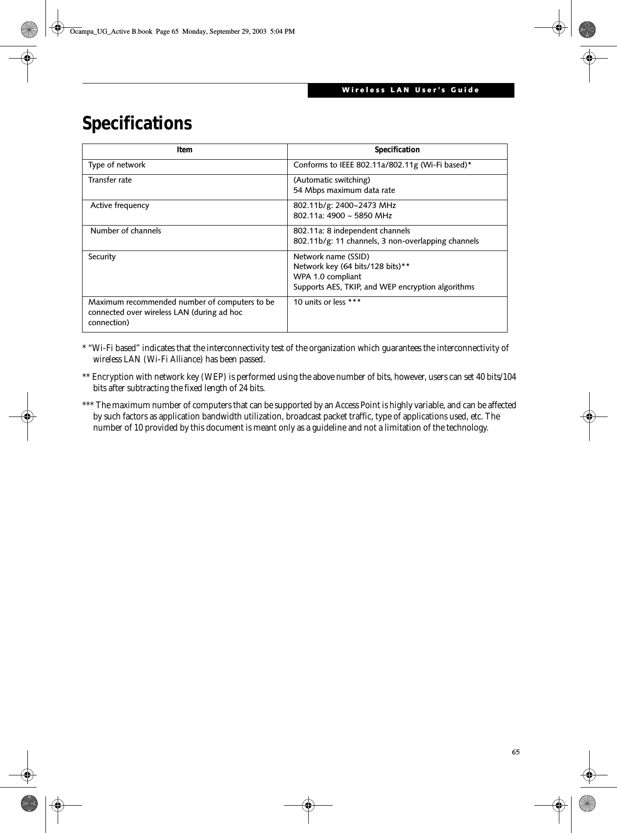
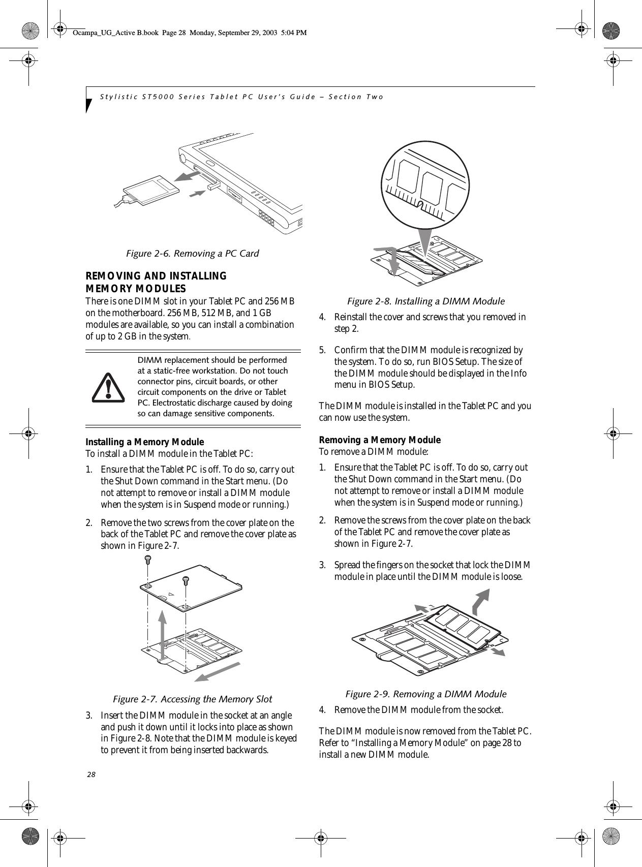
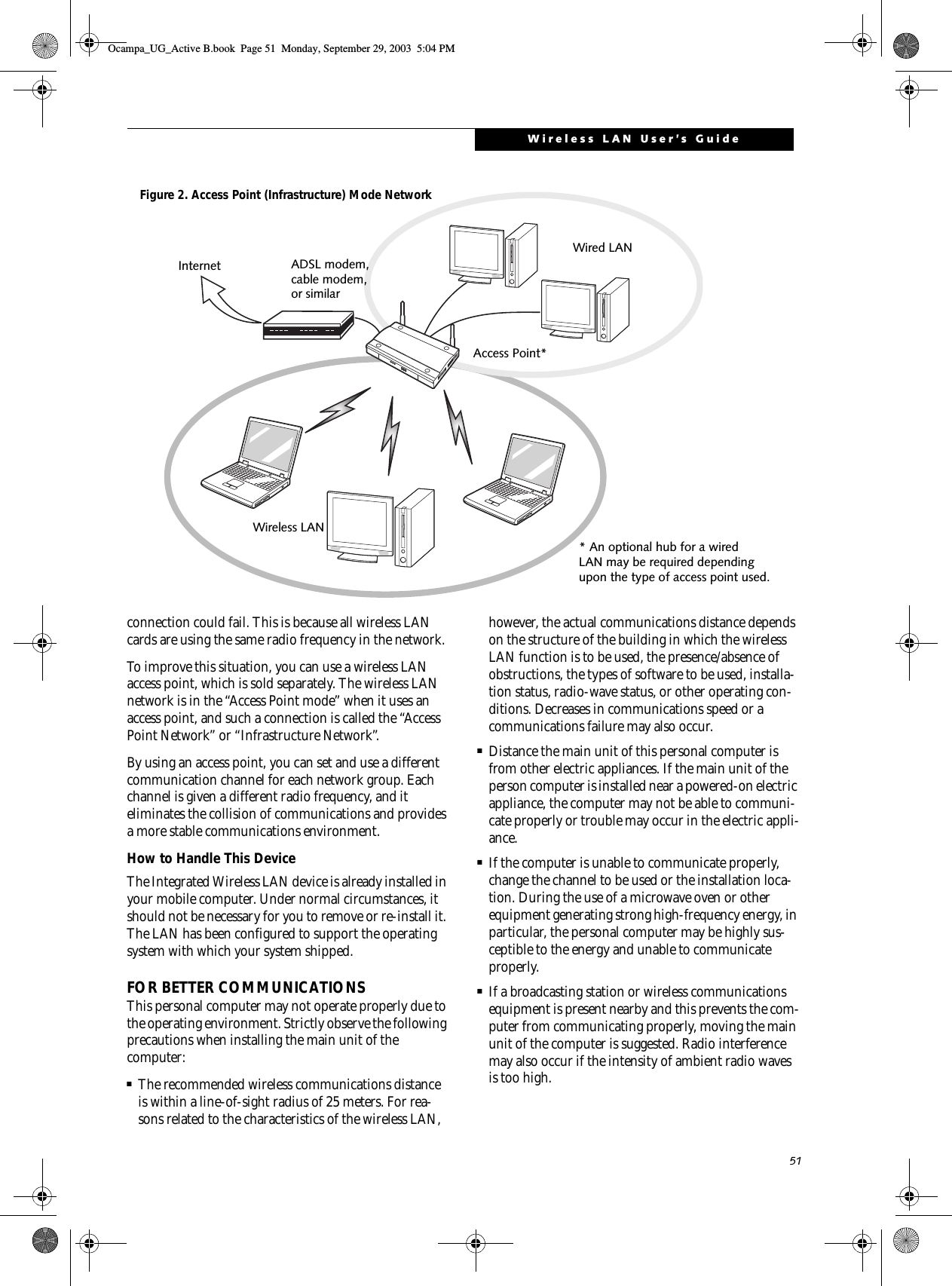
![50Stylistic ST5000 Series Tablet PC User’s Guide – AppendixBefore Using the Wireless LAN The Integrated Wireless LAN is a standard device on Stylistic ST5000 Tablet PC’s, and an option on Stylistic ST5000D Tablet PC’s. This manual describes the basic operating procedures for the Wireless LAN (referred to as the “device” in this manual) and how to set up a wire-less LAN network. Before using this device, read this manual carefully to ensure correct operation of the device. Keep this manual in a safe place for reference while using the device.Types of Wireless LANs Covered by this DocumentThis document is applicable to systems containing one of the following two devices. Most of the procedures are identical. Sections that differ between the two devices have been noted in the text:■Intel PROSet Wireless LAN■Atheros Wireless LANTo determine which device is present in your system, click [Start] -> Control Panel. If there is an icon named “Intel PROSet”, you have the Intel device; if there is an icon named “Atheros Client Utility”, you have the Atheros device. Characteristics of the DeviceThis device consists of a wireless LAN card that is attached inside the computer via a mini-PCI slot.The main characteristics are as follows:■It operates in the 2.4 GHz Industrial, Scientific, and Medical (ISM) RF band.■It does not require the procurement of an FCC license to operate.■It uses Direct Sequence Spread Spectrum (DS-SS), an RF modulation scheme that is resistant to noise.■This device complies with Wi-Fi, and is able to com-municate at the maximum transfer rate of 11 Mbps.■The maximum communication range is approxi-mately 80 feet (25 meters) inside a building. The range may be shorter depending upon the installation fac-tors, such as walls and columns.■Unauthorized access can be prevented with the use of an SSID and an encryption key (also known as a WEP key).Wireless LAN Modes Using this DeviceAd Hoc Mode (See Figure 1)“Ad Hoc Mode” refers to a type of wireless network that involves connecting multiple computers without the use of an Access Point. Network connectivity between computers can be established using only wireless LAN cards in a peer-to-peer fashion.Ad Hoc networks are an easy and inexpensive method for establishing network connectivity between multiple computers.In the Ad Hoc mode, you can use the function supported by Microsoft Network, such as File and Print Sharing to exchange files and share a printer or other peripheral devices.To use the Ad Hoc Mode, you must set the same SSID and the same encryption key for all the computers that are connected. All connected computers can communi-cate with each other within the communication range. Access Point (Infrastructure) Mode (See Figure 2)If a number of computers are connected simultaneously in the Ad Hoc mode, the transfer rate may be reduced, communications may become unstable, or the network Figure 1. Ad Hoc Mode NetworkOcampa_UG_Active B.book Page 50 Monday, September 29, 2003 5:04 PM](https://usermanual.wiki/Fujitsu-Client-Computing/WL0004.User-Manual/User-Guide-382909-Page-61.png)
![52Stylistic ST5000 Series Tablet PC User’s Guide – AppendixSTOPPING TRANSMISSION To use this product inside hospitals, clinics, or airplanes, or in other places where the use of electronic equipment is regulated, stop the transmission of radio waves from the wireless LAN beforehand.Deactivation using the wireless switchThe transmission of radio waves from the wireless LAN can be stopped by setting the wireless switch to the Off position. Note that the Wireless LAN On/Off switch has no effect on non-Wireless LAN models.(See Figure 3 for Wireless LAN switch location.)Figure 3. Wireless LAN On/Off SwitchDeactivation using WindowsIntel PROSet Wireless LAN:1. Click [Start] --> [(All) Programs] --> [Intel Net-work Adapters] --> [Intel(R) PROSet]. The Intel(R) PROSet window will be displayed.2. Click the General tab.3. Select [Off] for the wireless communications Switch Radio: function, and then click the [OK] button. Wireless communications on/off switching will be deactivated and the transmission of radio waves from the wireless LAN will be stopped.Atheros Wireless LAN1. Click [Start] --> [Control Panel] --> [Atheros Cli-ent Utility]. The Atheros Wireless Configuration Utility window will be displayed.2. Click the Wireless Networks tab.3. Click the [Enable Radio] box to clear it, then click the [OK] button. Wireless communications on/off switching will be deactivated and the transmission of radio waves from the wireless LAN will be stopped.STARTING TRANSMISSION To communicate using the wireless LAN function, set the computer to a status from which it can transmit, as follows:Intel PROSet Wireless LAN:1. Set the wireless switch to the On position. 2. Click [Start] --> [(All) Programs] --> [Intel Net-work Adapters] --> [Intel(R) PROSet]. The Intel(R) PROSet window will be displayed.3. Click the [General] tab if it is not already selected.4. Select [ON] for the Switch radio: function, then click [OK]. Wireless communications on/off switching will be activated and the transmission of radio waves will be restarted.Atheros Wireless LAN:1. Click the Wireless Network Connection icon in the system tray at the lower right of your screen.2. Click [Enable Radio]. The radio will be turned on.Access Point Mode: Transmission is enabled.Ad Hoc Mode: Restart your computer to enable the radio.To restart transmission, select [On] for the wireless communications Switch Radio: function, and then click the [OK] button.Wireless LANOn/OffSwitchTo restart transmission, check the [Enable Radio] checkbox to select it., then click the [OK] button.Ocampa_UG_Active B.book Page 52 Monday, September 29, 2003 5:04 PM](https://usermanual.wiki/Fujitsu-Client-Computing/WL0004.User-Manual/User-Guide-382909-Page-63.png)
![53Wireless LAN User’s GuideConnecting the WLANFLOW OF OPERATIONSThe wireless LAN connection procedure contained in this section is outlined below.1. Make sure the mobile computer is ready for the transmission of radio waves from the wireless LAN. For further details, see (See Starting Transmission on page 52 for more information.).2. Assign the parameters required for wireless LAN connection. (See Preparation for wireless LAN con-nection on page 53 for more information.).■Enter the network name (SSID) and other data.■Enter the network key (the Wired Equivalent Privacy or WEP key used to encode 802.11b communications data).3. Perform setting operations relating to network con-nection. (See Connection to the network on page 55 for more information.)■Specify TCP/IP as the protocol, and confirm the name of the work group and other settings.■Enter the data required for file/printer sharing on the network. Perform this operation as required.■For access point (or “infrastructure”) connection, enter data for the access point. Refer to the manual of the access point for further details.■Verify that you are able to connect your computer to the network.PREPARATION FOR WIRELESS LAN CONNECTIONThis section explains the preparations required for the use of the wireless LAN.Assigning parametersEnter the network name (SSID), the network key, and other data required for wireless LAN connection. If there is the administrator of the network, contact the network administrator for data settings.1. Make sure the Wireless LAN switch is switched on.2. Click the [Start] button first and then [Control Panel].3. If the Control Panel is in Category view, switch to Classic view by clicking “Switch to Classic View” under Control Panel the left frame. (If you are already in Classic view, “Switch to Category View” will be displayed instead.) 4. Double-click the Network Connections icon. A list of currently installed networks will be displayed.5. Right-click [Wireless Network Connection] in the list, and then click [Properties] in the menu dis-played. The [Wireless Network Connection Proper-ties] window will be displayed.6. Click the [Wireless Networks] tab.7. Click [Refresh], then choose the correct SSID from the [Available Networks] window. Click [Config-ure] and proceed to step 7. If the SSID of your access point does not appear in the list, click [Add]. The [Wireless Network Properties] window will be displayed.8. Select the Association tab if it is not already selected.9. Enter the information required for connection to the wireless LAN.a. Enter the network name (SSID). (i.e., Enter the name of the desired network in less than 33 ASCII characters).For ad hoc connection: Assign the same network name to all the personal computers to be connected.■To use access point (infrastructure) con-nection, refer to the access point manual for the access point-setting procedure.■You do not need to set the channel when using access point (infrastructure) mode. Channel selection is controlled by the access point. In ad hoc networks, channel selection defaults to channel 11; however, channel selection can be man-ually changed if desired. This can be accomplished only when using the client utility.If it is necessary to change the channel, change the setting of the access point. For the setting procedure, refer to the manual of the access point.Ocampa_UG_Active B.book Page 53 Monday, September 29, 2003 5:04 PM](https://usermanual.wiki/Fujitsu-Client-Computing/WL0004.User-Manual/User-Guide-382909-Page-64.png)
![54Stylistic ST5000 Series Tablet PC User’s Guide – AppendixFor access point (infrastructure) connection: Assign the appropriate SSID. The SSID must be identical to the SSID of the access point. Refer to the access point manual, or contact your network administrator.b. For ad hoc connection, check the following field. For access point (infrastructure) connection, clear the check mark for the following field:[This is a computer-to-computer (ad hoc) net-work; wireless access points are not used.]10. Enter the WEP key for encoding communications data.a. Check the [Data encryption (WEP enabled)] check boxFor ad hoc connection: Clear the check mark from the [Network Authentication (Shared mode)] check box.For access point (infrastructure) connection: If the access point to be accessed has acquired shared-key authentication, check the [Network Authentication (Shared mode)] check box.For open-system authentication, clear the check mark. For access point setting, refer to the man-ual of the access point.b. Clear the check mark from the [The key is provided for me automatically] check box.c. Enter data in [Network Key]. Depending on the number of entered characters or digits, whether the key is an ASCII character code or a hexadec-imal code will be identified automatically.■Use five or thirteen characters to enter the key in the ASCII character code format. The char-acters that can be used as the “network key” are as follows: 0 - 9, A - Z, _ (underscore), or, ■Use 10 or 26 characters to enter the key in the hexadecimal character code format. The char-acters that can be used as the “network key” in this case are as follows: 0- 9, A - Z, a - fFor ad hoc connection: Assign the same net-work key to all the personal computers to be connected.For access point (infrastructure) connection: Assign the identical network key that is pro-grammed into the access point. For this set-ting, refer to the access point manual or contact your network administrator.d. Confirm the Network key by re-entering the same data in the [Confirm network key:] field.e. Make sure that [Key index (advanced)] is set to “1”. (Any value from “1” to “4” can be assigned to [Key index (advanced)]. “1” is usually assigned, however).11. Click the [Authentication] tab and then verify the settings of [Enable network access control using IEEE 802.11x].For internal use at an organization such as a com-pany, when access by wireless LAN clients is to be limited using IEEE 802.11x authentication, check the [Enable network access control using IEEE 802.11x] check box.For home use, clear the check mark from [Enable network access control using IEEE 802.11x]. For the setting method relating to IEEE 802.11x authentication, refer to the manual of the access point which you are using.12. After completion of setting operations, click the [OK] button. Processing will return to the [Wire-less Network Connection Properties] window.13. Verify that the network name entered in step 7 above is added in [Preferred Networks], and then click the [OK] button.14. Close the [Wireless Network] window.It is strongly recommended that you enter the network key for encoding communications data. If the network key is not entered, since the network can be accessed from all personal computers containing the wireless LAN function, there is the danger of your data being stolen or damaged by other users.In [Preferred Networks], register only the desired connection settings.Ocampa_UG_Active B.book Page 54 Monday, September 29, 2003 5:04 PM](https://usermanual.wiki/Fujitsu-Client-Computing/WL0004.User-Manual/User-Guide-382909-Page-65.png)
![55Wireless LAN User’s GuideCONNECTION TO THE NETWORKThis section explains connection to the network.If there is an administrator of the network, contact the network administrator for data settings.Setting the networkPerform the “Setting TCP/IP” and “Confirming the computer and work group names” operations required for network connection.Setting TCP/IP1. Click the [Start] button first and then [Control Panel].2. If the Control Panel is in Category view, switch to Classic view by clicking “Switch to Classic View” under Control Panel the left frame. (If you are already in Classic view, “Switch to Category View” will be displayed.) 3. Double-click [Network Connections]. A list of cur-rently installed networks will be displayed.4. Right-click [Wireless Network Connection] in the list, and then click [Properties] in the menu dis-played. The [Wireless Network Connection Proper-ties] window will be displayed.5. Click the [General] tab if it is not already selected.6. Click [Internet Protocol (TCP/IP] and then click [Properties]. The [Internet Protocol (TCP/IP) Properties] window will be displayed.7. Set the IP address as follows:■For ad hoc connection: Select [Use the following IP address:] and then enter data for [IP address] and [Subnet mask]. See page 64 for IP address setting.■For access point (infrastructure) connection: If your network uses DHCP, select [Obtain an IP address automatically] and [Obtain DNS server address automatically]. If your network uses static IP addresses, consult with your network adminis-trator for the correct IP address settings.8. Click the [OK] button. Processing will return to the [Wireless Network Connection Properties] window.9. Click the [OK] button.10. Close the [Network Connection] window. Following this operation, confirm the names of the computer and the workgroup as follows.Confirming the computer and work group names1. Click the [Start] button, then [Control Panel].2. If the Control Panel is in Category view, switch to Classic view by clicking “Switch to Classic View” under Control Panel the left frame. (If you are already in Classic view, “Switch to Category View” will be displayed.) 3. Double-click the [System] icon. The [System Prop-erties] window will be displayed.4. Click the [Computer Name] tab.5. Confirm the settings of [Full computer name:] and [Workgroup:].a. The setting of [Full computer name:] denotes the name for identifying the computer. Any name can be assigned for each personal computer. Enter the desired name in less than 15 ASCII character code format. Identifiability can be enhanced by entering the model number, the user name, and other factors.b. [Workgroup name] is the group name of the network. Enter the desired name in less than 15 ASCII character code format.For ad hoc connection: Assign the same network name to all personal computers existing on the network.For access point (infrastructure) connection: Assign the name of the work group to be accessed.6. Click the [OK] button. If a message is displayed that requests you to restart the personal computer, click [Yes] to restart the computer.Setting the sharing functionSet the sharing function to make file and/or printer sharing with other network-connected personal computers valid.To change the setting of the IP address, you need to be logged in from Windows as an administrator.To modify the computer name and/or the work group name, you need to be logged in from Windows as an administrator.To change the name, click [Change] and then proceed in accordance with the instruction messages displayed on the screen.Ocampa_UG_Active B.book Page 55 Monday, September 29, 2003 5:04 PM](https://usermanual.wiki/Fujitsu-Client-Computing/WL0004.User-Manual/User-Guide-382909-Page-66.png)
![56Stylistic ST5000 Series Tablet PC User’s Guide – AppendixThis operation is not required unless the sharing func-tion is to be used.The folder and printer for which the sharing function has been set will be usable from any personal computer present on the network.Setting the Microsoft network-sharing service1. Click the [Start] button first and then [Control Panel]. 2. If the Control Panel is in Category view, switch to Classic view by clicking “Switch to Classic View” under Control Panel the left frame. (If you are already in Classic view, “Switch to Category View” will be displayed.) 3. Double-click [Network Connections]. A list of cur-rently installed networks will be displayed.4. Right-click [Wireless Network Connection] in the list, and then click [Properties] in the menu dis-played. The [Wireless Network Connection Proper-ties] window will be displayed.5. If [File and Printer Sharing for Microsoft Net-works] is displayed, proceed to step 6. If [File and Printer Sharing for Microsoft Networks] is not dis-played, skip to step 7.6. Make sure that the [File and Printer Sharing for Microsoft Networks] check box is checked, and then click the [OK] button. Skip to “Setting file-sharing function”.7. Click [Install]. The [Select Network Component Type] window will be displayed.8. Click [Service], then click the [Add] button. The [Select Network Service] window will be displayed.9. Click [File and Printer Sharing for Microsoft Net-works] and then click the [OK] button. Processing will return to the [Wireless Network Connection Properties] window, and [File and Printer Sharing for Microsoft Networks] will be added to the list.10. Click the [Close] button.Setting the file-sharing functionThe procedure for setting the file-sharing function follows, with the “work” folder in drive C: as an example.1. Click the [Start] button first and then [My Com-puter]. 2. Double-click [Local disk (C:)].3. Right-click the “work” folder (or whichever folder you want to share), and then click [Sharing and Security...] in the menu displayed. The [Folder Name Properties] window will be displayed.4. Click [Sharing] if it isn’t already selected.5. Click the link stating “If you understand the secu-rity risks, but want to share files without running the wizard, click here”.6. Click “Just enable file sharing” and click [OK].7. Check the [Share this folder on the network] check box.8. Click the [OK] button. The folder will be set as a sharable folder, and the display of the icon for the “work.” folder will change.Setting the printer-sharing function1. Click the [Start] button first and then [Printers and FAX]. A list of connected printers will be displayed.2. Right-click the printer for which the sharing func-tion is to be set, and then click [Sharing] in the menu displayed. The property window correspond-ing to the selected printer will be displayed.3. Click the [Sharing] tab.4. Click [Share this printer].To share a file and/or the connected printer, you need to be logged in as an administrator.Setting the file-sharing function for the file which has been used to execute Network Setup Wizard is suggested on the screen. For the wireless LAN, however, since security is guaranteed by entry of the network name (SSID) and the network key, the steps to be taken to set the file-sharing function easily without using Network Setup Wizard are given below.To specify the corresponding folder as a read-only folder, select the [Read only] checkbox under the General tab.Setting the printer-sharing function when Network Setup Wizard has been executed is suggested on the screen. For the wireless LAN, however, since security is guaranteed by entry of the network name (SSID) and the network key, the steps to be taken to set the printer-sharing function without using Network Setup Wizard are laid down below.Ocampa_UG_Active B.book Page 56 Monday, September 29, 2003 5:04 PM](https://usermanual.wiki/Fujitsu-Client-Computing/WL0004.User-Manual/User-Guide-382909-Page-67.png)
![57Wireless LAN User’s Guide5. Enter the sharing printer name in [Share name].6. Click the [OK] button. Confirming connectionAfter you have finished the network setup operations, access the folder whose sharing has been set for other personal computers. Also, confirm the status of the radio waves in case of trouble such as a network connection failure.Connecting your personal computer to another personal computer1. Click [Start] first and then [My Computer]. The [My Computer] window will be displayed in the left frame.2. Click [My Network Places] in the “Other Places” list. The window [My Network Places] will be dis-played.3. Click [View workgroup computers] under Network Tasks in the left frame.4. Double-click the personal computer to which your personal computer is to be connected. The folder that was specified in “Setting the file-sharing func-tion” on page 56 will be displayed.5. Double-click the folder to be accessed.Confirming the status of the radioIntel PROSet Wireless LAN:1. Click [Start] -> [All Programs] -> [Intel Network Adapters] -> [Intel(R) PROSet]. The [Intel(R) PROSet] window will be displayed.2. Click the [General] tab and confirm radio status in the window displayed. The current connection sta-tus will be displayed.■Signal QualityThe quality of the signals is displayed on a graph.■Network name (SSID)The connected network name (SSID) is displayed.■Profile name“<No profile>” is displayed.■ModeIf access point (infrastructure) connection is in use, “Infrastructure (AP)” will be displayed. If ad hoc connection is in use, “Ad hoc (Peer-to-peer)” will be displayed.■SecurityThe setting status of WEP is displayed.■SpeedThe communications speed is displayed.■Band (Frequency)The current operating frequency band is displayed. When communication is possible, “802.11b (2.4 GHz)” is displayed.■ChannelThe channel number currently being used for the communications is displayed.If connection cannot be made to the network or if you want to check for normal connection, see “Trouble-shooting” on page 60.Atheros Wireless LAN:1. Right-click the Atheros icon in the lower right cor-ner of the screen.2. Click [Open Client Utility]. The Atheros Wireless Configuration Utility window opens.3. Contained within the Current Status tab and Advanced Current Status, you will find the current operating status of the radio. (When the radio is turned off or the computer is not yet connected, some of the conditions will not be displayed.)■Profile NameThe current configuration profile is displayed.■Network Type - Configured Network Type[Access Point] or [AdHoc] will be displayed.■Current ModeIndicates the frequency and data rate currently used by the radio.■Current ChannelThe channel number currently used by the radio.■Link StatusDisplays the current connected state of the WLAN module.■Encryption TypeDisplays the encryption type currently used by the radio.■IP AddressDisplays the current TCP/IP address assigned to the WLAN adapter.■CountryThe country with the country code for which the radio is configured.In the case of access point (infrastructure) connection, enter the necessary data for the access point before confirming connection. Refer to the manual of the access point for the access point setup procedure.Ocampa_UG_Active B.book Page 57 Monday, September 29, 2003 5:04 PM](https://usermanual.wiki/Fujitsu-Client-Computing/WL0004.User-Manual/User-Guide-382909-Page-68.png)
![58Stylistic ST5000 Series Tablet PC User’s Guide – Appendix■Transmi t Power LevelDisplays the current transmit power level of the radio.■Network Name (SSID)Displays the Network Name (SSID) currently used by the radio.■Power Save ModeDisplays the configured Power Save Mode currently used by the radio. [Off], [Normal], or [Maximum] will be displayed.■BSSIDDisplays the Basic Service Set Identifier. This is typically the MAC address of the Access Point or in the case of AdHoc networks, is a randomly generated MAC address.■FrequencyDisplays the center frequency currently being used by the radio.■Transmi t Ra teDisplays the current data rate used by the radio to transmit data.■Receive RateDisplays the current data rate used by the radio to receive data.Ocampa_UG_Active B.book Page 58 Monday, September 29, 2003 5:04 PM](https://usermanual.wiki/Fujitsu-Client-Computing/WL0004.User-Manual/User-Guide-382909-Page-69.png)
![59Wireless LAN User’s GuideOther settingsSETTING OF POWER-SAVING FUNCTIONYou can set the power-saving function of wireless LAN. Default setting is auto-setting. In case of using the power-saving function, manually control the communication performance.Intel PROSet Wireless LAN:1. Click [Start] -> [(All) Programs] -> [Intel Network Adapters] -> [Intel(R) PROSet]. The Intel(R) PROSet window will be displayed.2. Click the [Adapter] tab.3. Click the [Configure] button in [Power settings]. The [Power settings] window will be displayed.4. Select [Manual], and adjust the bar to set the power-saving function.Setting of transmission power during ad hoc connectionBy controlling the transmission power during ad hoc connection, you can broaden or narrow the communica-tion range. This setting is only effective during ad hoc connection. It will be ineffective during access point connection.Intel PROSet Wireless LAN:1. Click [Start] -> [(All) Programs] -> [Intel Network Adapters] -> [Intel(R) PROSet]. The Intel(R) PROSet window will be displayed.2. Click the [Adapter] tab.3. Click the [Configure] button in [Power settings]. The [Power settings] window will be displayed.4. Adjust the “Transmission Power (Ad Hoc)” bar to set the transmission power.Setting of channels during ad hoc connectionYou can set channels during ad hoc connection. Channel 11 is set by default. When connecting to an existing ad hoc network, no channel setting will be effective.This setting is only effective during ad hoc connection; it will be ineffective during access point connection.Intel PROSet Wireless LAN:1. Click [Start] -> [(All) Programs] -> [Intel Network Adapters] -> [Intel(R) PROSet]. The Intel(R) PROSet window will be displayed.2. Click the [Adapter] tab.3. Click the [Configure] button in [Ad hoc settings]. The [Ad hoc settings] window will be displayed.4. Change channels during ad hoc connection by selecting a new channel from the drop down list.5. Click [OK].Atheros Wireless LAN:1. Click on the My Computer icon. Select [View sys-tem information] from the left frame.2. Select the Hardware tab and click [Device Manager].3. Double-click “Atheros BCM4306 Wireless LAN Adapter” under [Network Adapters].4. In the Atheros BCM4306 Wireless LAN Adapter window, select the Advanced tab.5. Select IBSS Channel Number from the list, and change the value from the [Value:] dropdown list to the desired channel.6. Click [OK].When changing channels during ad hoc connection, change the channel settings of all connected computers with the same Network name (SSID) at the same time. After changing the channels, turn off all computers and -- after they are all turned off -- turn them back on.Ocampa_UG_Active B.book Page 59 Monday, September 29, 2003 5:04 PM](https://usermanual.wiki/Fujitsu-Client-Computing/WL0004.User-Manual/User-Guide-382909-Page-70.png)
![60Stylistic ST5000 Series Tablet PC User’s Guide – AppendixTroubleshootingCauses and countermeasures for troubles you may encounter while using your wireless LAN are described in the following table. Problem Possible Cause Possible SolutionUnavailable network connectionIncorrect network name (SSID) or network keyAd hoc connection: verify that the network names (SSID’s) and network keys (WEP) of all computers to be connected have been configured correctly. SSID’s and WEP key values must be identical on each machine.Access Point (Infrastructure) connection: set the network name (SSID) and network key to the same values as those of the access point. Set the Network Authentication value identically to that of the Access Point. Please consult your network administrator for this value, if necessary. For the method of setting network authentication, refer to the following pages:· “Assigning parameters” on page 53· Poor radio wave condition Ad hoc connection: Retry connection after shortening the distance to the destination computer or removing any obstacles for better sight.Access Point (Infrastructure) connection: Retry connection after short-ening the distance to the access point or removing any obstacles for better sight.To check the wave condition, refer to the following pages:· “Confirming the status of the radio waves” on page 57.·Radio wave transmission has stoppedCheck if the wireless switch is turned ON. Also verify “Disable Radio” is not checked in “Network setting” window. Refer to “Starting Transmis-sion” on page 52.The computer to be connected is turned offCheck if the computer to be connected is turned ON.Active channel duplication due to multiple wireless LAN networksIf there is any other wireless LAN network nearby, change channels to avoid active channel duplication. For the method of checking active channels, refer to the following pages:· “Confirming the status of the radio waves” on page 57· No right of access to the network to be connectedCheck if you have a right of access to the network to be connected with.Incorrectly-performed network settingCheck the protocol, work group name or shared setting.For the method of checking, refer to the following pages:· “Connection to the Network” on page 55.Unmatched [Network authentication (shared mode)] settings in Windows XPIf the setting of [Network authentication (shared mode)] is not matched with that of access point or computer to be connected with, no commu-nication can be established. Check the parameter setting.Refer to “Assigning parameters” on page 53.Ocampa_UG_Active B.book Page 60 Monday, September 29, 2003 5:04 PM](https://usermanual.wiki/Fujitsu-Client-Computing/WL0004.User-Manual/User-Guide-382909-Page-71.png)
![61Wireless LAN User’s GuideUnavailable network connection(continued)It takes too long to retrieve the network and display the connected computers.Retrieve computers as follow: 1. Click [Start] button, then click [Search].2. Click [Computers or people].3. Click [Computers on the network].4. Input the name of computer to be connected with in [Computer name] and click [Search].5. Double-click the icon of connected computer.· Incorrect setting of IP address Check the network setting.“Setting the network” on page 55. In case of using TCP/IP protocol, you can check IP address as follows:1. Click [Start] -> [All programs] -> [Accessories] -> [Command prompt].· 2. In [Command prompt] or [MS-DOS prompt] window, input [IPCONFIG] command as follows, then press [Enter] key.Example: In case of C drive being the hard disk: C:\ipconfig [Enter]Check that the IP address is correctly displayed:.IP Address................: 10.0.1.3Subnet Mask.............: 255.255.255.0Default Gateway.........: 10.0.1.1When IP address is displayed as [169.254.XXX.YYY] or [0.0.0.0], IP address is not correctly fetched from the access point. In that case, restart the computer itself. If the display is still unchanged, check the setting of TCP/IP.If [Cable Disconnected] or [Media Disconnected] is displayed without showing IP address, check the setting of network name (SSID) and network key. Also, set the network authentication according to the access point.Communication is disconnected soon after connection to the access point Access control may be disabled Check the setting of “Enable network access control using IEEE 802.1X”.Refer to “Assigning parameters” on page 53.When restricting the access of wireless LAN clients using IEEE802.1X authentication, put a check mark on “Enable network access control using IEEE 802.1X”.When using at home, remove a check mark on “Enable network access control using IEEE802.1X”.For the method of setting related with IEEE802.1X authentication, refer to the access point manual.Problem Possible Cause Possible SolutionOcampa_UG_Active B.book Page 61 Monday, September 29, 2003 5:04 PM](https://usermanual.wiki/Fujitsu-Client-Computing/WL0004.User-Manual/User-Guide-382909-Page-72.png)
![64Stylistic ST5000 Series Tablet PC User’s Guide – AppendixIP address informationIf IP address is unknown, set IP address as follows:If you have an access point (DHCP server) on the network, set the IP address as follows:[Obtain an IP address automatically]If the IP address is already assigned to the computer in the network, ask the network administrator to check the IP address to be set for the computer.If no access point is found in the network:An IP address is expressed with four values in the range between 1 and 255.Set the each computer as follows: The value in paren-theses is a subnet mask.<Example>Computer A: 192.168.100.2 (255.255.255.0)Computer B: 192.168.100.3 (255.255.255.0)Computer C: 192.168.100.4 (255.255.255.0)::Computer X: 192.168.100.254 (255.255.255.0)IP addressing is much more complicated than can be briefly explained in this document. You are advised to consult with your network administrator for additional information.A DHCP server is a server that automatically assigns IP addresses to computers or other devices in the network. There is no DHCP server for the AdHoc network.Ocampa_UG_Active B.book Page 64 Monday, September 29, 2003 5:04 PM](https://usermanual.wiki/Fujitsu-Client-Computing/WL0004.User-Manual/User-Guide-382909-Page-75.png)