Fujitsu Technology Solutions SCENICM702 User Manual A26361 K515 Z100 1 7619
Fujitsu Technology Solutions GmbH A26361 K515 Z100 1 7619
SCENIC Edition Mi Operating Manual August 1998 edition

A26361-K515-Z100-1-7619 1
Introduction
This Operating Manual tells you how to put your PC into operation and how to operate it in daily use.
It applies for all configuration levels. Depending on the configuration level chosen some of the
hardware components described may not be available on your PC. Please observe the notes on
your operating system.
Your SCENIC Edition Mi is a powerful PC which is suitable for both professional and private use.
You can incorporate operable drives (for example CD-ROM drive, DAT drive, streamer) as well as
other boards.
Depending on the configuration level chosen, your PC is supplied with Windows 9x or Windows NT
as the operating system.
Your PC has a number of security features to ensure that no unauthorized persons can access your
data. For example, you can activate a screen saver with password protection. The security functions
in the BIOS Setup also allow you to protect your data by means of passwords.
Further information on this PC is provided:
• in the manual „Safety and Ergonomics“
• in the Operating Manual for the monitor
• in the Technical Manual for the system board
• in the manual "BIOS Setup"
• in the documentation of your operating system
• in the information files (e. g. *.TXT, *.WRI, *.DOC, *.HLP)
iSome of the manuals listed can be found on the CD "Drivers & Utilities" provided with your
computer. These manuals can be read and printed with the Acrobat Reader contained on
the CD.

Introduction Notational conventions
2A26361-K515-Z100-1-7619
Notational conventions
The meanings of the symbols and fonts used in this manual are as follows:
!Pay particular attention to texts marked with this symbol. Failure to observe this warning
endangers your life, destroys the system, or may lead to loss of data.
iThis symbol is followed by supplementary information, remarks and tips.
Texts which follow this symbol describe activities that must be performed in the order shown.
Texts in italics indicate commands or menu item.
"Quotation marks" indicate names of chapters and terms that are being emphasized.

A26361-K515-Z100-1-7619 3
Important notes
In this chapter you will find information regarding safety which it is essential to take note of when
working with your PC. The manufacturer's notes contain helpful information on your PC.
Safety
!Pay attention to the information provided in the manual "Safety and Ergonomics".
• During installation and before operating the device, observe the instructions on environmental
conditions in the chapter entitled "Technical data" as well as the instructions in the chapter
"Preparation for use and operation".
• Please check whether the device is set to the local power supply (see chapter "Preparation for
use and operation").
• The On/Off switch does not separate the system unit completely from the line voltage. To
disconnect the line voltage completely, remove the power plug from the grounded power outlet.
• When cleaning the device, observe the relevant notes in the paragraph "Cleaning the PC".
• When connecting and disconnecting cables, observe the relevant notes in the chapter
"Preparation for use and operation".
• Replace the lithium battery on the system board in accordance with the instructions in the
chapter "System expansions - Memory, processor, lithium battery".
• Caution: components on the system board can get very hot.
• Keep this Operating Manual together with your device. If you pass on the device to third
parties, you should also pass on this manual.

Important notes Manufacturer's notes
4A26361-K515-Z100-1-7619
Notes on installing and removing boards
Boards with electrostatic sensitive devices (ESD) may be identified by labels.
When you handle boards fitted with ESDs, you must observe the following points under all
circumstances:
• You must always discharge yourself (e.g. by touching a grounded object) before working.
• The equipment and tools you use must be free of static charges.
• Pull out the power plug before inserting or pulling out boards containing ESDs.
• Always hold boards with ESDs by their edges.
• Never touch pins or conductors on boards fitted with ESDs.
Manufacturer's notes
Energy saving
When the PC is delivered, some energy-saving functions are already set (see Technical Manual for
the system board or the manual "BIOS Setup").
• If you are not using your PC, switch it off.
• In the BIOS Setup you may set further energy-saving functions for the PC (see the Technical
Manual of the system board or in the manual "BIOS Setup").
Energy saving under Windows NT
If the attached monitor and screen controller support power management in accordance with VESA
(DPMS), a screen saver can be used to switch the monitor into power management mode. This
function is dependent on the screen controller and screen driver used.
Energy saving under Windows 9x
Using the DeskLock program you can lock the mouse and keyboard so that no input can be made. If
the attached monitor supports power management in accordance with VESA (DPMS), it can be
switched into power-saving mode at the same time.
In addition the Screen Saver tab allows you to set energy-saving functions for your screen. Select the
following item in the Start menu: Settings - Control Panel - Display - Display Properties - Screen Saver -
Energy saving features of monitor.
With the default setting Control Panel - Power - Advanced additional energy saving features of
Windows 9x are available.
Manufacturer's notes Important notes
A26361-K515-Z100-1-7619 5
Disposal and recycling
This device has been manufactured to the greatest possible degree from materials which can be
recycled or disposed of in a manner that is not environmentally damaging. The device is taken back
after use, so that it can be recycled, provided that it is returned in a condition which is the result of
normal use. Any components not recuperated will be disposed of in an environmentally acceptable
manner.
For devices marked with this symbol Siemens AG offers a guarantee
for 36 months with a Bring-in-Service. The guarantee starts on the
day of delivery (sale date) by Siemens or a Siemens partner.
We herewith declare that it will be possible to repair any device
marked with the eco-label for at least 5 years after production of that
device has discontinued.
Information on power management and energy saving mode can be
found in chapter "Technical data".
Do not throw lithium batteries or accumulators into the trashcan. They must be disposed of in
accordance with local regulations concerning special waste.
If you have any questions on disposal, please contact your local office, our service department, or,
directly:
Siemens AG
Recycling Center
D-33094 Paderborn
Tel.: 49 5251 818 010
Fax: 49 5251 818 015
CE certificate
The shipped version of this device complies with the requirements of the EEC directives
89/336/EEC "Electromagnetic compatibility" and 73/23/EEC "Low voltage directive".
Important notes Manufacturer's notes
6A26361-K515-Z100-1-7619
FCC Class B Compliance Statement
If there is an FCC statement on the device, then:
The following statement applies to the products covered in this manual, unless otherwise specified
herein. The statement for other products will appear in the accompanying documentation.
NOTE:
This equipment has been tested and found to comply with the limits for a "Class B" digital device,
pursuant to Part 15 of the FCC rules and meets all requirements of the Canadian Interference-
Causing Equipment Regulations. These limits are designed to provide reasonable protection against
harmful interference in a residential installation. This equipment generates, uses and can radiate
radio frequency energy and, if not installed and used in strict accordance with the instructions, may
cause harmful interference to radio communications. However, there is no guarantee that
interference will not occur in a particular installation. If this equipment does cause harmful
interference to radio or television reception, which can be determined by turning the equipment off
and on, the user is encouraged to try to correct the interference by one or more of the following
measures:
• Reorient or relocate the receiving antenna.
• Increase the separation between equipment and the receiver.
• Connect the equipment into an outlet on a circuit different from that to which the receiver is
connected.
• Consult the dealer or an experienced radio/TV technician for help.
Siemens AG is not responsible for any radio or television interference caused by unauthorized
modifications of this equipment or the substitution or attachment of connecting cables and
equipment other than those specified by Siemens AG. The correction of interferences caused by
such unauthorized modification, substitution or attachment will be the responsibility of the user.
The use of shielded I/O cables is required when connecting this equipment to any and all optional
peripheral or host devices. Failure to do so may violate FCC rules.
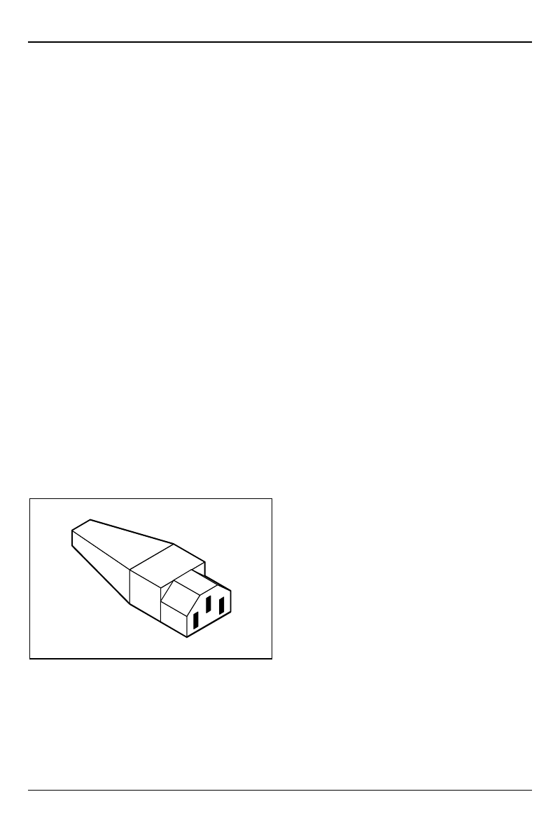
Power cord selection
The power cord for this unit has been packed
separately and has been selected according to
the country of destination. It must be used to
prevent electric shock. Use the following
guidelines if it is necessary to replace the
original cord set.
The female receptacle of the cord set must meet
CEE-22 requirements (see Figure).
Manufacturer's notes Important notes
A26361-K515-Z100-1-7619 7
For the United States and Canada
Use a UL listed and CSA labeled cord set consisting of a three conductor cord with a maximum
length of 15 feet.
For units which stand on a desk or table, type SVT or SJT cord sets shall be used.
For units which stand on floor, only SJT type cord sets shall be used.
The cord set must be selected according to the current rating for your unit. Please consult Table A
for the selection criteria for power cords used in the United States and Canada.
Table A:
Cord Type Size of Conductors
in Cord Maximum Current
Rating of Unit
SJT 18 AWG
16 AWG
14 AWG
10 Amps
12 Amps
12 Amps
SVT 18 AWG
17 AWG 10 Amps
12 Amps
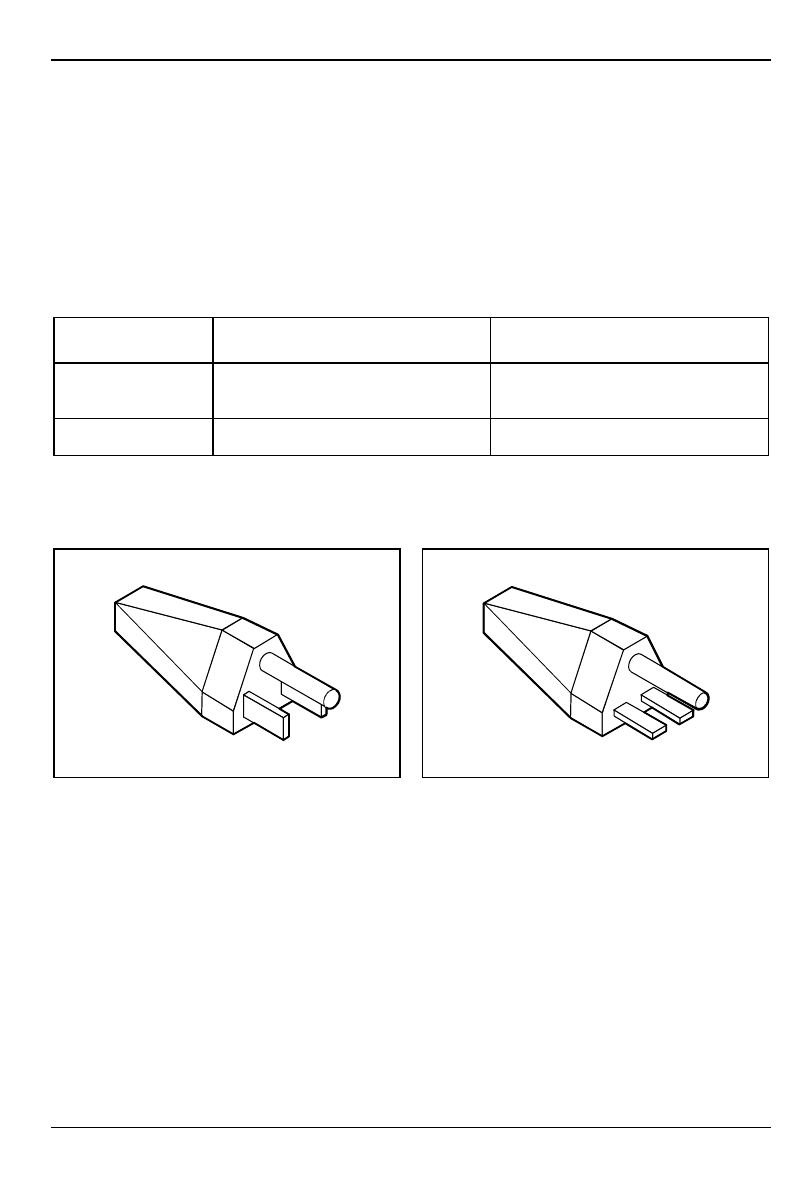
For units set at 115 V:
use a parallel blade, grounding type attachment
plug rated 15 A, 125 V.
For units set at 230 V (domestic use):
use a tandem blade, grounding type attachment
plug rated 15 A, 250 V.
For units set at 230 V (outside of the United States and Canada):
use a cord set consisting of a minimum AWG according to Table A and a grounding type attachment
plug rated 15 A, 250 V. The cord set should have the appropriate safety approvals for the country in
which the equipment will be installed and should be marked HAR.

Important notes Transporting the PC
8A26361-K515-Z100-1-7619
For the United Kingdom
Should the plug on the flexible cord not be of the type for your socket outlets, do not use an adapter
but remove the plug from the cord and discard. Carefully prepare the end of the supply cord and fit a
suitable plug.
WARNING
THIS APPLIANCE MUST BE EARTHED
IMPORTANT
The wires in this mains lead are colored in accordance with the following code:
Green and Yellow: Earth
Blue: Neutral
Brown: Live
As the colors of the wires in the mains lead of this appliance may not correspond with the colored
markings identifying the terminals in your plug, proceed as follows:
• The wire which is colored Green and Yellow must be connected to the terminal in the plug
which is marked with the letter E or by the earth symbol or colored Green or Green and Yellow.
• The wire which is colored Blue must be connected to the terminal which is marked with the
letter N or colored Black.
• The wire which is colored Brown must be connected to the terminal which is marked with the
letter L or colored Red.
Transporting the PC
!Transport all parts separately, and in their original packaging or in a packaging which
protects them from knocks and jolts, to the new site. Do not unpack them until all transport
maneuvers are completed.
Never drop the monitor (danger of implosion)!
Cleaning the PC Important notes
A26361-K515-Z100-1-7619 9
Cleaning the PC
!Turn off all power and equipment switches and pull the power plug out of the grounded
power outlets.
Do not clean any interior parts yourself, leave this job to a service technician.
Do not use any cleaning agents that contain abrasives or may corrode plastic.
Ensure that no liquid enters the system.
Ensure that the ventilation areas of the system unit and the monitor are free.
Cleaning the system unit and the monitor
Wipe the system unit and monitor casing with a dry cloth. If particularly dirty, use a cloth which has
been moistened in mild domestic detergent and then carefully wrung out.
Cleaning the keyboard and the mouse
Use a cloth for disinfection to clean the keyboard and the mouse.
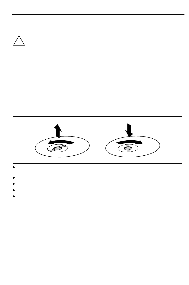
Remove the retaining ring on the underside of the mouse and then clean the mouse mechanism and
the rotating ball.
1
23
4
Using both thumbs exert downward pressure on the notches of the retaining ring and turn the
ring anticlockwise (1).
Remove the retaining ring and the rotating ball from the mouse (2).
Clean the three small wheels in the mouse and the ball with a lint-free cloth.
Replace the ball and the retaining ring (3).
Using both thumbs exert downward pressure on the notches of the retaining ring (4) and turn
the ring clockwise. You must feel the ring engage.

A26361-K515-Z100-1-7619 11
Preparation for use and operation
!Please take note of the safety information in the chapter "Important notes".
Unpacking and checking the delivery
It is recommended not to throw away the original packaging material! It may be required for
reshipment at some later date.
Unpack all the individual parts.
Check the delivery for damage incurred during transport.
Check whether the delivery agrees with the details in the delivery note.
Check whether all necessary details have been entered on the first page of the guarantee
coupon booklet.
Should you discover that the delivery does not correspond to the delivery note, notify your local
sales office immediately.
iIf you have received drives or boards with your PC, please do not install them until
after first-time setup. How to install drives and boards is described in the chapter
"System expansions".
Preparing the PC for use
First-time setup includes the connection of the devices (monitor, mouse, keyboard etc.) and the
setup of the supplied software.
When you set up the PC for the first time, you should carry out the following steps in the order
shown:
1. Decide where you are going to use the PC.
2. Connect the external devices to the system unit.
3. Check the rated voltage of the system unit and connect it to the line voltage.
4. Switch the PC on and follow the instructions on the screen.

Preparation for use and operation Setting up the PC
12 A26361-K515-Z100-1-7619
Setting up the PC
!When installing your PC, give consideration to the recommendations on video workstation
ergonomics in the manual "Safety and Ergonomics".
Set up the PC only in its correct orientation. The points to observe are illustrated on the
following pages.
We recommend that you place your equipment on a surface with good anti-slip qualities.
In view of the multitude of different finishes and varnishes used on furniture, it is possible
that the rubber feet of the devices will mark the surface they stand on.
Do not expose the PC to extreme environmental conditions (see chapter "Technical
data"). Protect it from dust, humidity and heat.
Provide at least 200 mm of clearance on the left, in front of and behind the ventilator area
of the system unit to ensure adequate ventilation. Do not cover the ventilation areas of the
monitor and the fan.
Do not place several system units one above the other.
Connecting devices
!The power plug must be disconnected!
Read the documentation on the external device before connecting it.
Do not connect or disconnect cables during a thunderstorm.
Always take hold of the actual plug body. Never unplug a cable by pulling the cable itself!
Connect and disconnect the cables in the order described below.
Connecting cables
• Turn off all power and equipment switches.
• Unplug all power plugs from the grounded power outlets.
• Connect all cables at the system unit and peripherals. You must observe the information
provided in the chapter "Important notes".
• Plug all data communication cables into the utility sockets.
• Plug all power cables into the grounded power outlets.
Disconnecting cables
• Turn off all power and equipment switches.
• Unplug all power plugs from the grounded power outlets.
• Unplug all data communication cables from the utility sockets.
• Disconnect all cables from the system unit and peripherals.
Connecting devices Preparation for use and operation
A26361-K515-Z100-1-7619 13
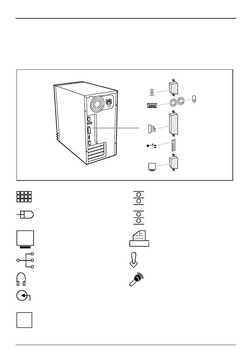
Ports for external devices
The ports for external devices are on the rear of the system unit. The ports available on your PC
depend on the configuration level you have selected. The standard ports are marked with symbols
like those below or similar symbols. Exact details of the position of the ports are supplied in the
Technical Manuals for the boards.
Example for the location of connections
Keyboard port 1Serial port 1
PS/2 mouse port 2Serial port 2
Video connector Parallel port
USB - Universal Serial Bus Game port
Audio output (Line out) Microphone jack
Audio input (Line in) LAN LAN-port
iSome of the devices that you connect require special drivers (see the documentation for
the connected device and for the operating system).
Preparation for use and operation Connecting devices
14 A26361-K515-Z100-1-7619
Connecting the mouse
Plug the connector of the mouse cable into the mouse port.
iIf you attach a serial mouse, you can disable the mouse controller in the BIOS-Setup in
order to free the IRQ12 for a different application. If the mouse controller is disabled, you
will not be able to operate a mouse connected to the PS/2 mouse port.
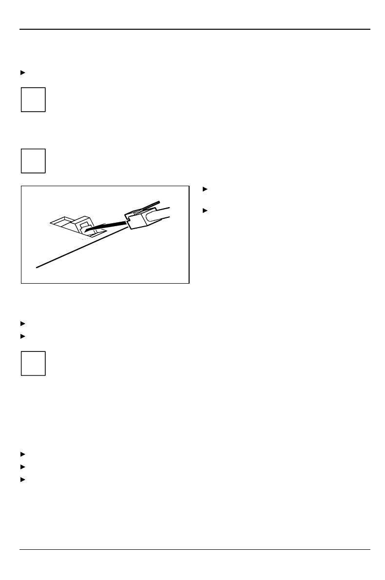
Connecting the keyboard
iUse only the keyboard cable supplied.
Plug the round plug of the keyboard cable
into the keyboard port on the system unit.
Plug the other connector of the keyboard
cable into the socket on the underside of
the keyboard.
Connecting devices with serial or parallel port
Connect the data cable to the external device.
Connect the data cable of the external device to the appropriate port on the system unit.
iMost devices that you connect to the serial or parallel port require special drivers. Your
operating system already includes many drivers . But if the driver you need is not on the
hard disk please install it from the floppy disk supplied with the device or with the
application program.
If you need to change the default settings of the serial or parallel port (e.g. address,
interrupt), you can do so in the BIOS Setup. The default setting for the interfaces are
described in the Technical Manual for the system board or in the "BIOS Setup" manual.
Connecting the monitor to the line voltage
Prepare the monitor as described in the Operating Manual for the monitor.
Plug the data cable of the monitor into the monitor port of the system unit.
Plug the power cable of the monitor into the grounded power outlet (2).
Connecting the PC to the line voltage Preparation for use and operation
A26361-K515-Z100-1-7619 15
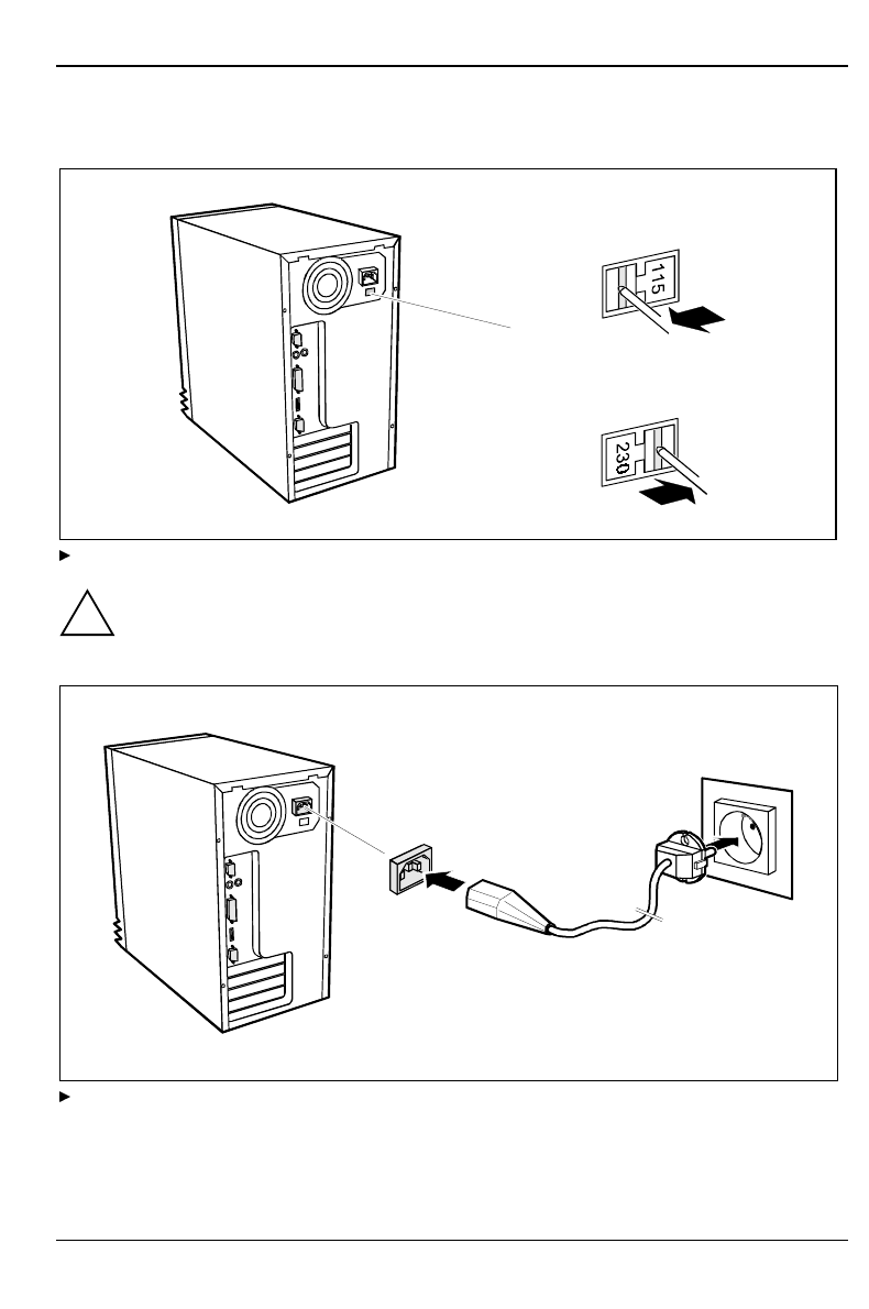
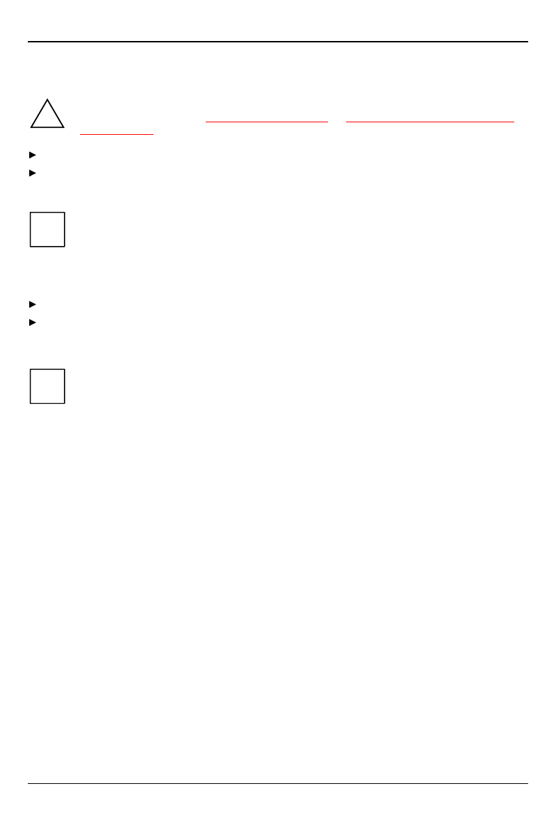
Connecting the PC to the line voltage
100 V - 125 V
200 V - 240 V
Check the rated voltage.
!115 = 100 V to 125 V 230 = 200 V to 240 V
If the rated voltage does not agree with the local line voltage, you must move the wiper
switch to the correct position.
1
2
Plug the system unit's power cable into the system unit (1) and then into the grounded power
outlet (2).
Preparation for use and operation Indicators and switches
16 A26361-K515-Z100-1-7619
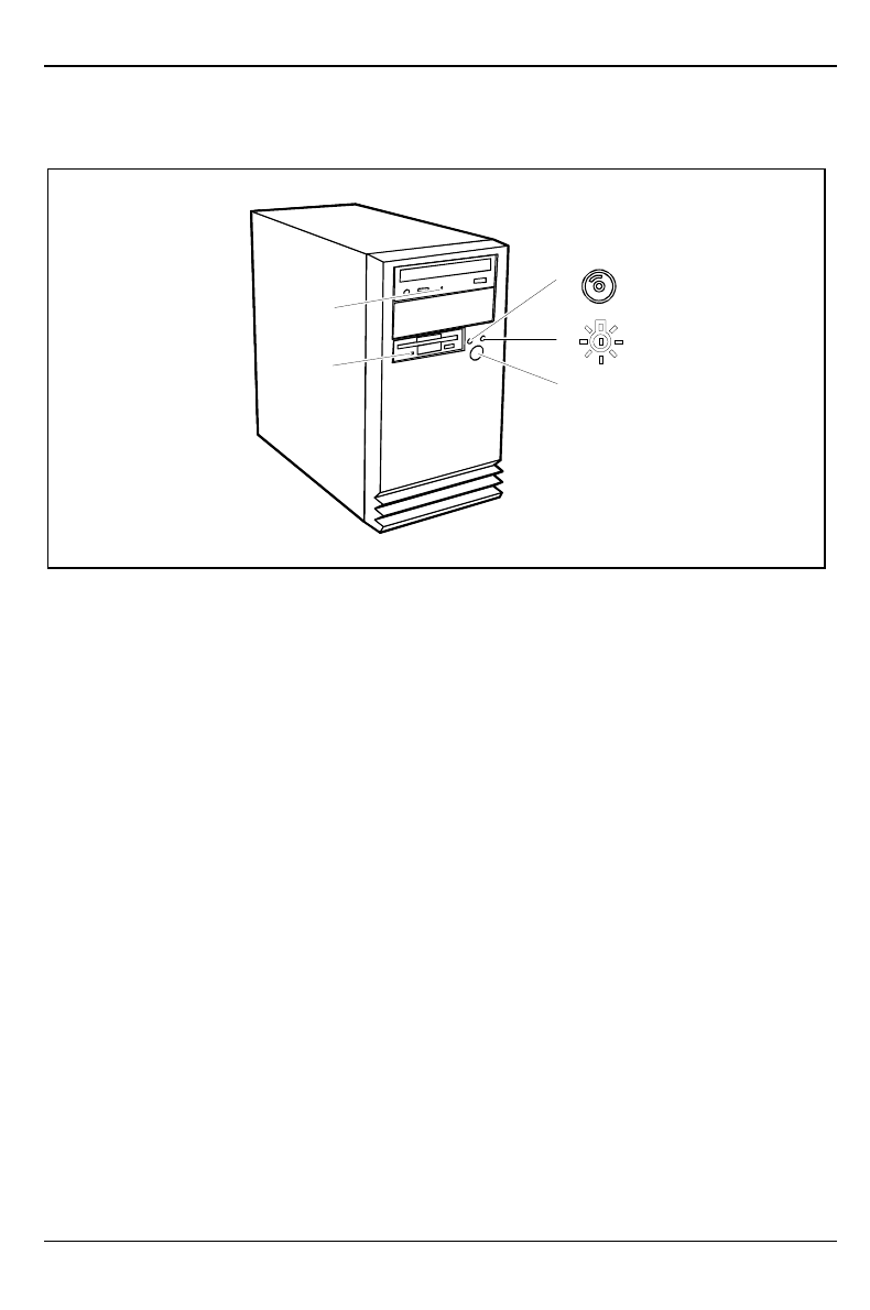
Indicators and switches
1
2
3
4
5
1 = CD-ROM indicator
2 = Floppy disk indicator
3 = Hard disk indicator
4 = Power-on indicator
5 = ON/OFF switch
1 - CD-ROM indicator
The indicator lights up when the CD-ROM drive of the system unit is accessed. You may only
remove the CD when the indicator is dark.
2 - Floppy disk indicator
The indicator lights up when the floppy disk drive of the system unit is accessed. You may only
remove the floppy disk when the indicator is dark.
3 - Hard disk indicator
The indicator lights up when the hard disk drive of the system unit is accessed.
4 - Power-on indicator
The indicator lights up green when the system unit is switched on.
The indicator lights up orange when the system unit is switched off.
5 - ON/OFF switch
Switches the PC on or off.
Indicators and switches Preparation for use and operation
A26361-K515-Z100-1-7619 17
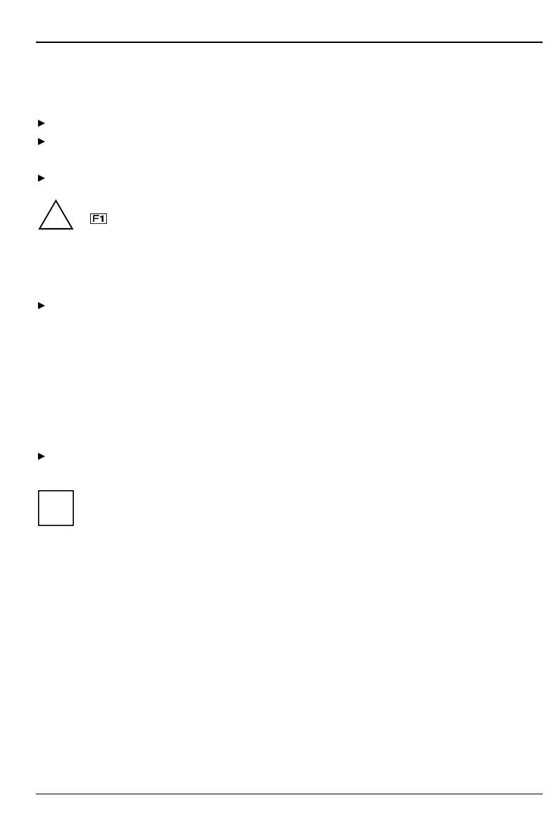
Switching on the PC for the first time
When you switch on your PC for the first time the supplied software is set up and configured.
Switch your monitor on.
Switch the system unit on with the ON/OFF switch.
The power-on indicator lights green and the PC is started.
Adjust the brightness if necessary (see the Operating Manual for the monitor).
!Some variants require you to start the software installation by pressing the function key
.
Once the installation has been started the PC must not be switched off.
You should only reboot the PC during installation if you are requested to do so. Otherwise
the installation will be not be performed correctly. If a fault occurs in the installation the
contents of the hard disk must be completely restored.
During installation follow the instructions on the screen.
Consult the operating system manual if there is anything unclear about the requested input data.
If the PC is integrated into a network, the user and server details as well as the network protocol are
required. Contact your network administrator if you have any questions about these details.
The license number for Windows is printed on the front cover of the Windows manual supplied.
Some system configurations do not include a Windows CD in the delivery package. In this case you
should create a backup copy after installing Windows so that you can restore the hard disk contents
in an emergency.
You need about 40 diskettes for this.
Create Windows diskettes with the MSCSD backup program (create system diskettes) and label
them using the labels supplied.
iYou will find further information about the system, drivers, utilities, updates, and manuals
etc. on the "Drivers & Utilities" CD supplied.
Preparation for use and operation Indicators and switches
18 A26361-K515-Z100-1-7619
Switching on the PC
!If after switching on the PC you see nothing but flickering stripes on the screen, switch the
PC off immediately (see "Troubleshooting and tips" - "Flickering or drifting stripes on the
monitor screen").
Switch the monitor on (see the Operating Manual for the monitor).
Switch the system unit on with the ON/OFF switch.
The power-on indicator lights green and the PC is started.
iIf you have assigned the system password, you must enter this when requested to do so,
in order to start the operating system.
Switching off the PC
Shut down the operating system properly. Windows in the Start menu via the Quit function.
If the operating system does not automatically switch the system unit off, turn the system unit
off when requested to do so by pressing the On/Off switch. If the system unit is switched off,
the power-on indicator lights up orange.
iThe On/Off switch does not separate the system unit from the line voltage. To disconnect
the line voltage completely, remove the power plug from the grounded power outlet.
If the system unit is off, the system board consumes very little power.
Working with floppy disks Preparation for use and operation
A26361-K515-Z100-1-7619 19
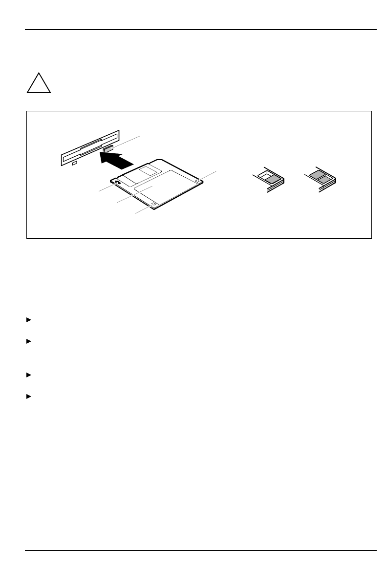
Working with floppy disks
!Follow the instructions supplied by the vendor of the floppy disks.
Never clean the floppy disk drives with cleaning disks. Even just one attempt would
destroy the read/write head in the disk drive within 20 seconds.
3
2
1
5
6
47
1 = Insertion direction
2 = Label area
3 = Write protection tab for a 720 Kbyte or a 1,44 Mbyte floppy disk
4 = Identification of a 1,44 Mbyte floppy disk or write protect tab on a 120 Mbyte floppy disk
5 = Eject button for inserted floppy disks
6 = Floppy disk is write protected
7 = Floppy disk is not write-protected
To insert a floppy disk, push it into the drive in the insertion direction (1) until it engages. The
label should be facing upward.
To remove the floppy disk, press the eject button (5).
The write-protect slider enables you to protect the data on the floppy disk from inadvertent
overwriting or deletion.
To protect the data on the floppy disk from being overwritten, push the write-protect slider to
position (6). The hole is now visible.
To remove write protection, push the slider to position (7). The hole is now covered.
Preparation for use and operation Keyboard
20 A26361-K515-Z100-1-7619
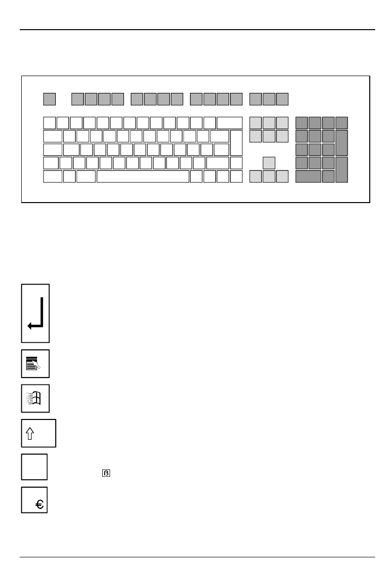
Keyboard
1
234
1 = function keys
2 = alphanumeric keypad 3 = cursor control keys
4 = numeric keypad (calculator keypad)
Important keys and key combinations
The following description of keys and key combinations refers to MS Windows. Details of other keys
and key combinations can be found in the documentation of the relevant application program.
Enter key
confirms or starts the marked selection. The enter key is also referred to as the
"Return" key or "Carriage Return".
Start key
invokes the START menu.
Menu key
invokes the menu for the marked item.
Shift key
enables upper-case letters and the upper key symbols to be displayed.
Alt Gr
Alt Gr
produces a character shown on the right-hand side of a key (e. g. the character "\" on
the key ).
EEuro key
produces the Euro character (Windows 98 and Windows NT5.0).
Settings in BIOS Setup Preparation for use and operation
A26361-K515-Z100-1-7619 21
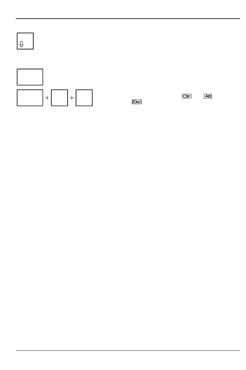
Num Num Lock key
by pressing the Num Lock key you switch between the upper- and lower-case levels
of the calculator keypad.
At upper-case level (Num Lock indicator lit) the digit and comma keys are active.
At lower-case level (Num Lock indicator not lit) the cursor control functions are active
in the calculator keypad.
Ctrl
Ctrl key
starts key combination actions.
Ctrl Alt Del
Warm boot
restarts your PC. First hold down the and key, and
then press the key.
Settings in BIOS Setup
The BIOS Setup
menu allows you to set your hardware configuration and system functions. When the
notebook is delivered, the default entries are valid. You can customize these settings to your
requirements in BIOS Setup.
The Technical Manual for the system board shows you how to call and operate BIOS Setup. The
menus and setting options provided by BIOS-Setup are also described in detail.
Property and data protection
Your PC enable you to protect your system and personal data in a number of ways against
unauthorized access.
Security functions under Windows 9x
Under Windows 9x you can activate a screen saver and protect it with a password. Only those users
who know the password can deactivate the screen saver and access any open files. Detailed
information on screen savers under MS Windows is provided by the associated help function.
BIOS Setup security functions
The Security menu in BIOS Setup offers you various options for protecting your system and personal
data against unauthorized access. By combining these options, you can achieve optimum protection
for your system. You will find a detailed description of the Security menus and how to assign
passwords in the Technical Manual for the system board.


A26361-K515-Z100-1-7619 23
Troubleshooting and tips
!Take note of the safety hints in the manual "Safety and Ergonomics" and in the chapter
"Preparation for use and operation", when you connect or disconnect cables.
If a fault occurs, try to correct it as described:
• in this chapter
• in the documentation of the connected devices
• in the help systems of the software used.
If you fail to correct the problem, proceed as follows:
Switch the PC off.
Make a note of the steps and the circumstances that led to the fault. Also make a note of any
error messages displayed and the Ident-No. (Identnr.) of the type label of your device.
Contact your sales office or customer service.
Installing new software
When installing programs or drivers, important files may be overwritten and modified. To be able to
access the original data in the case of any problems following installation, you should make a
backup of the your hard disk prior to installation.
Power-on indicator remains dark after you have
switched on your device
This may have the following causes:
The line voltage supply is faulty
Check that the power cable is plugged properly into the system unit and grounded power outlet.
Internal power supply overloaded
Disconnect the power plug of the system unit from the grounded power outlet.
Plug the power plug into the grounded power outlet again.

Troubleshooting and tips
24 A26361-K515-Z100-1-7619
The screen stays blank
If your screen remains blank this may have the following causes:
Monitor is switched off
Switch your monitor on.
Screen has been blanked
Press any key on the keyboard.
or
Deactivate screen blanking (screen saver). Enter the appropriate password.
Brightness control is set to dark
Set the brightness control to light. For detailed information, please refer to the Operating
Manual supplied with your monitor.
Power cable or monitor cable not connected
Switch off the monitor and the system unit.
Check that the power cable is properly connected to the monitor and system unit or to the
grounded power outlet.
Check that the monitor cable is properly connected to the system unit or monitor (if not
permanently attached).
Switch on the monitor and the system unit.
Wrong monitor has been set under Windows NT
Restart the PC in standard VGA mode.
Set the desired resolution in the Control Panel window using the Display program, and adjust
the monitor display as described in the Operating Manual.
Wrong monitor has been set under Windows 9x
Restart the PC.
If the message Starting Windows 9x appears, press function key .
The Windows 9x start menu appears.
Select the option Safe mode or Safe mode with network support.
Set the correct values for the attached monitor by selecting Start - Settings - Control Panel -
Display - Settings.
The wrong RAM memory modules have been inserted
See the Technical Manual for the system board for information on which memory modules can
be used.

Troubleshooting and tips
A26361-K515-Z100-1-7619 25
Flickering or drifting stripes on the monitor screen
!Switch off the PC immediately!
The flickering stripes are caused either by an old-type screen that does not support the horizontal
frequency of 47 kHz, or by an incorrect monitor selection under MS-Windows.
The drifting screen display is caused when the selected frequency and/or resolution is wrong.
The default screen values are 800x600 pixels at 75 Hz and for 64K colors.
Find out which horizontal frequency your monitor screen supports.
You will find the horizontal frequency (also known as line frequency or horizontal deflection
frequency) in the documentation of your monitor.
No mouse pointer displayed on the screen
Shut down the operating system properly.
Switch the PC off.
Check that the mouse cable is properly connected to the system unit.
If you use an adapter or extension lead with the mouse cable, check the connector.
Make sure that only one mouse is connected.
Switch the PC on.
The mouse controller must be enabled, if you use a PS/2 mouse. Check in the BIOS Setup that
the mouse controller is enabled.
Check that the mouse driver is properly installed and is present when the application program
is started. Detailed information can be found in the User Guide of the mouse or application
program.
The floppy disk cannot be read or written
Check that the write protection of the floppy disk or the floppy disk drive is activated (refer also
to the Technical Manual of the system board or in the manual BIOS).
Check the relevant entries for Diskette A: or B: in the Main menu of the BIOS Setup.
Check that the floppy disk drive controller is enabled (refer also to the Technical Manual of the
system board or in the manual "BIOS Setup").
Check that the cables of the floppy disk drive are properly connected (refer to chapter "System
expansions").

Troubleshooting and tips
26 A26361-K515-Z100-1-7619
Time and/or date is not correct
Set the time and/or date. You can set the time and date in the BIOS Setup or in the operating
system.
iIf the time and date are repeatedly wrong when you switch on your PC, the battery is flat.
Change the lithium battery as described in the Chapter "Memory, processor, lithium
battery".
Error messages on the screen
Error messages and their descriptions are listed in the Technical Manual of the system board or in
the "BIOS Setup" manual and in the documentation of the installed software.
Restoring the hard disk contents
Your PC is supplied with different software components. These software components are usually
already preinstalled on the hard disk and is either ready for use immediately after initial startup or
initialized for setup or installation.
If your hard disk is however damaged, or programs or parts thereof have been accidentally deleted,
then recovery of the relevant programs or the entire contents of the hard disk is necessary.
The PC can be put into operation again with the backup diskettes, the Windows CD provided, the
drivers provided on floppy disks or CD and the CD with the applications program.
iAll data on the hard disk will be deleted. Operating system, drivers and software utilities
will be reinstalled. For this reason you should try to save important data before you restore
the hard disk contents.
Restoring hard disk contents with a Windows CD
Proceed as described in the related documentation.
Restoring the hard disk contents using the backup diskettes
Insert the first backup disk and follow the instructions on the screen.
Install the drivers and utilities in the C:\PROGS\DISKS directory.
Restoring the hard disk contents under Windows NT
If you need to restore the hard disk contents you have to reinstall Windows NT.
Proceed as described in the related documentation.

Troubleshooting and tips
A26361-K515-Z100-1-7619 27
Tips
The PC cannot be switched off with the ON/OFF switch
Cause: The PC has not been switched on with the ON/OFF switch.
Press the ON/OFF switch again.
Cause: System crash
Press the ON/OFF switch for at least four seconds, until the device switches off.
Out of system resources
If you have too many applications running at once, you may experience problems due to a lack of
system resources. If this happens, you should close applications you do not require or call the
applications in a different order.
BIOS settings in power management do not become active
The Auto insert notification setting may be active for the CD-ROM drive. This setting causes
Windows 9x to inquire about any modifications on the drive at regular intervals. Because of this the
timer for the idle time cannot time out.
To activate power management, proceed as follows:
In Windows 9x, select Start - Settings - Control Panel - System - Device Manager - CD-ROM.
Select the installed CD-ROM drive from the list.
Select Settings.
Deactivate the Auto insert notification box.
CD-ROM drive
Information on the CD-ROM drive can be found in the manual of the CDROM drive or on the
"Drivers & Utilities" CD.
Other manuals
Other manuals are contained on the "Drivers & Utilities" CD.

A26361-K515-Z100-1-7619 29
System expansions
!It may be necessary to update the BIOS when carrying out a system expansion or
hardware upgrade. In this instance, please contact our service.
This chapter describes all the activities required to modify your PC hardware (e.g. installing boards
or drives).
Memory and processor upgrading are described in the Technical Manual for the system board.
Read the supplied documentation before installing new drives and/or boards.
Refer to the Technical Manual for the system board before making any extensions on the system
board.
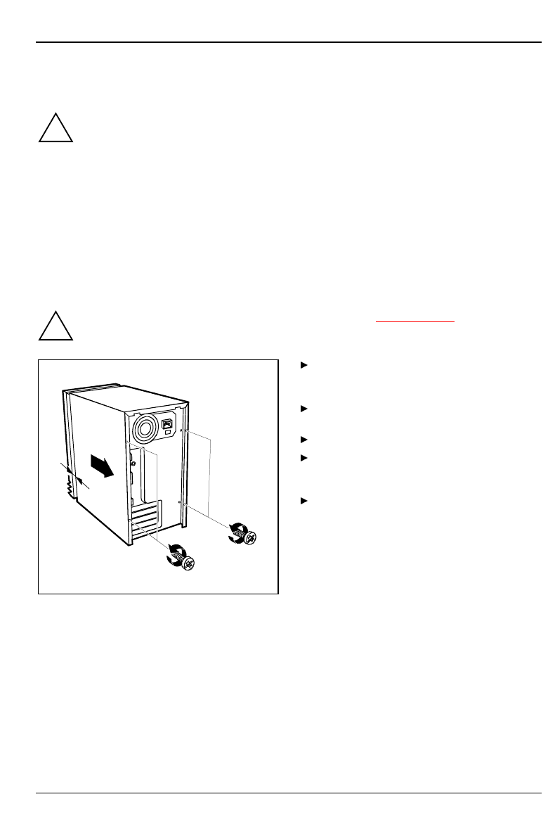
Opening the system unit
!Please take note of the safety information in the chapter "Important notes".
Pull the power plug out of the power outlet!
2
11
a
If any cables attached to the system unit
are obstructing you, pull out the connectors
on the system unit.
Place the system unit in a convenient
working position.
Loosen the screws (1).
Pull the casing in the direction of the
arrow (2) until the distance (a) is
approximately 10 mm.
Lift the casing in an upward direction.
System expansions
30 A26361-K515-Z100-1-7619
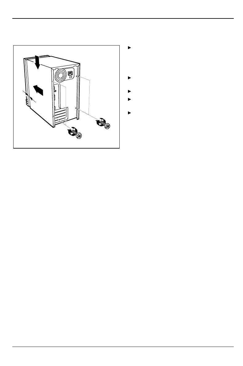
Assembling the system unit
2
33
1
a
Place the housing on the system unit (1)
from above so that the distance (a) is
approx. 10 mm. While doing so, make sure
that the housing is hooked into the system
unit at the bottom.
Push the casing in the direction of the
arrow (2).
Fasten the screws (3).
Return the system unit to its original
position.
If you have disconnected cables, reconnect
them at the rear.
Installing and removing drives
The system unit houses a total of three accessible drives (two 5 1/4-inch drives and one 3 1/2-inch
drive) and one non-accessible half-height (Slimline) drive.
IDE drives
By default four IDE drives are supported. Ideally hard disks are connected to IDE port 1, and
accessible drives, for example CD-ROMs, to IDE port 2 (see also the Technical Manual for the
system board).
SCSI drives
If you want to install an SCSI drive, you require an SCSI controller and an SCSI cable. Note that:
• not every SCSI controller is suitable for operating SCSI hard disks
• each SCSI device must be assigned its own SCSI-ID
• a device with activated or connected terminating resistors must always be connected at the
end of an SCSI cable. The terminating resistors of all other SCSI devices attached must not be
activated or connected.
System expansions
A26361-K515-Z100-1-7619 31
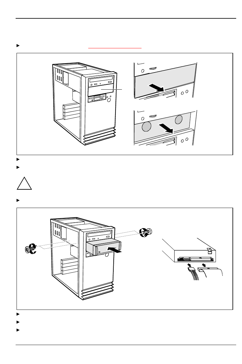
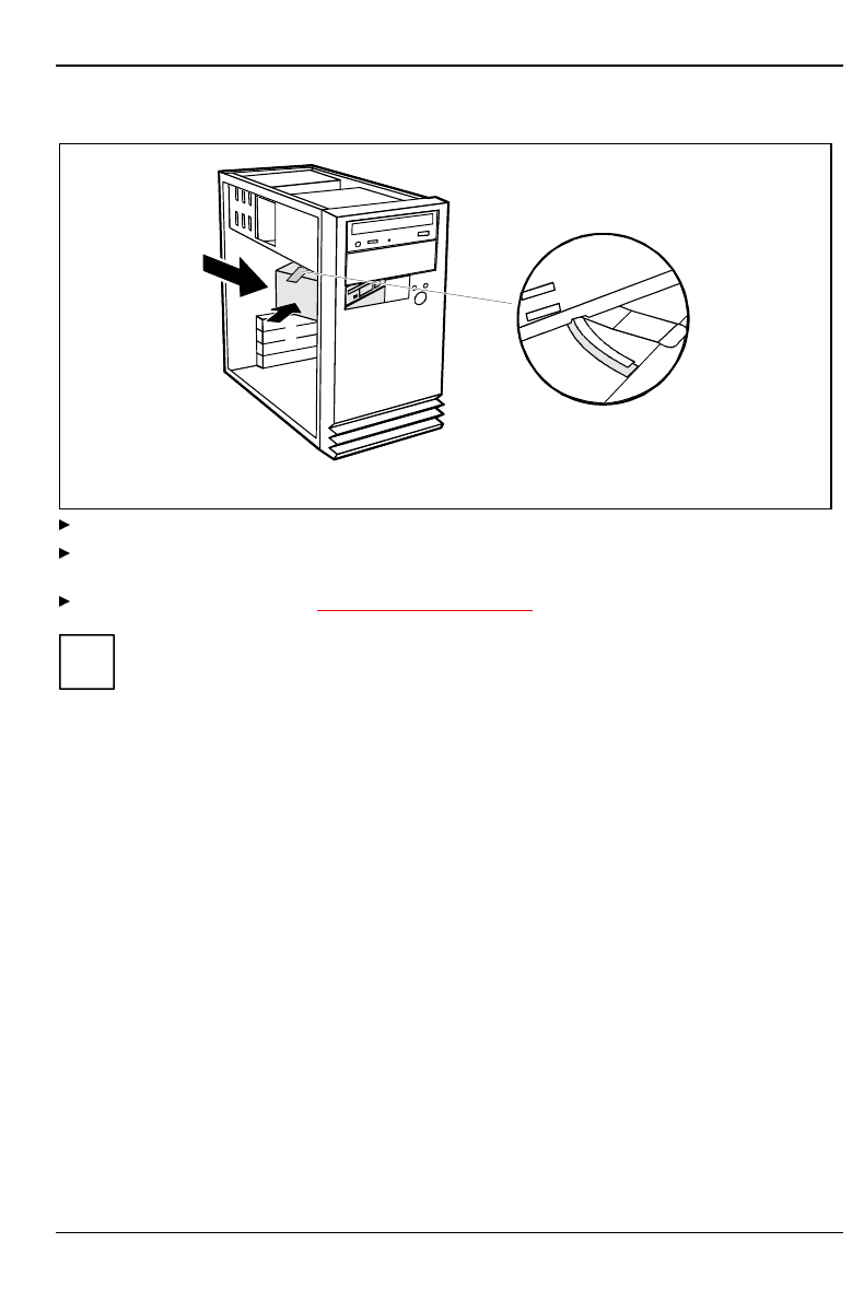
Installing an accessible drive
Open the system unit (see "Opening the system unit").
1
2
Lever out the plastic drive cover off the casing (1).
Pull the metal cover forward (2).
!If you remove the drive again later, you will have to reinstall the covers.
Make the required settings on the drive (if necessary, on installed drives as well).
1
2
3
2
Slide the drive into the system unit (1).
Fasten the drive with the screws (2).
Plug the connectors of the data cable and the power supply cable into the drive (3).
System expansions
32 A26361-K515-Z100-1-7619
Close the system unit (see "Assembling the system unit").
If necessary, you must adapt the entry for the drive in the Setup menu.
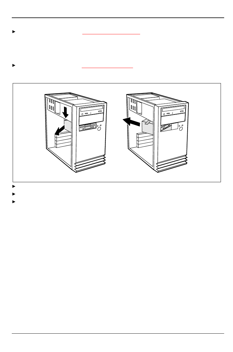
Replacing the hard disk or floppy disk drive
Open the system unit (see "Opening the system unit").
Removing the drive carrier
2
1
3
Press the unlocking device in the direction of the arrow (1).
Swivel the drive carrier in direction of the arrow (2).
Remove the drive carrier in direction of the arrow (3).
System expansions
A26361-K515-Z100-1-7619 33
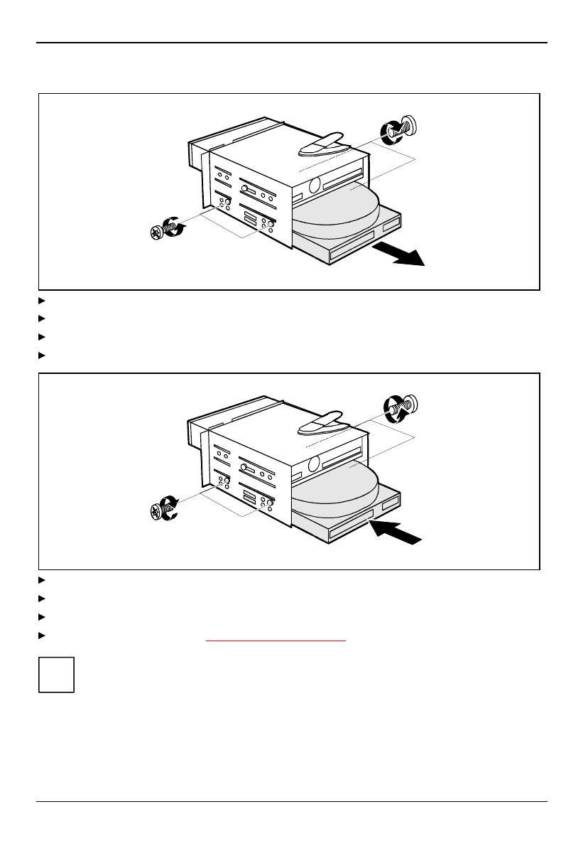
Replacing a hard disk drive
1
1
2
Remove the four screws (1).
Pull the hard disk drive out of the carrier (2).
Take the new hard disk drive out of its packaging.
Make the required settings (e.g. master-slave settings) on the drive.
1
2
2
Slide the hard disk drive into the drive carrier (1).
Fasten the hard disk drive with the screws (2).
Plug the data and the power supply connectors into the hard disk drive.
Close the system unit (see "Assembling the system unit").
iIf necessary, you must adapt the entry for the drive in the Setup menu.
System expansions
34 A26361-K515-Z100-1-7619
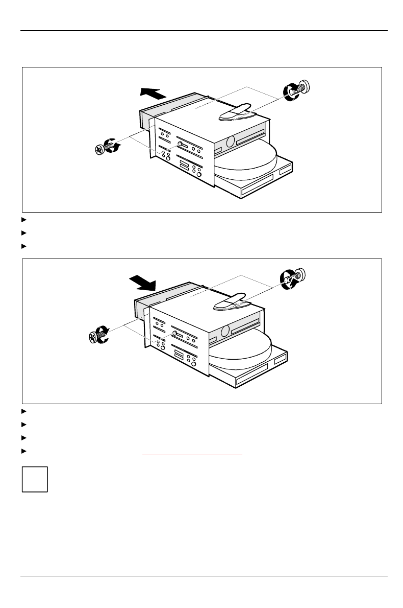
Changing the floppy disk drive
1
2
1
Remove the four screws (1).
Pull the floppy disk drive out of the carrier (2).
Take the new floppy disk drive out of its packaging.
1
2
2
Slide the floppy disk drive into the drive carrier (1).
Fasten the hard disk drive with the screws (2).
Plug the data and the power supply connectors into the hard disk drive.
Close the system unit (see "Assembling the system unit").
iIf necessary, you must adapt the entry for the drive in the Setup menu.
System expansions
A26361-K515-Z100-1-7619 35
Installing the hard disk carrier
1
2
Slide the drive carrier in direction of the arrow (1).
Swivel the drive carrier in direction of the arrow (2). Please ensure that the guide rail is in the
groove.
Close the system unit (see "Assembling the system unit").
iIf necessary, you must adapt the entry for the drive in the Setup menu.
System expansions
36 A26361-K515-Z100-1-7619
Installing a board
!Observe the notes on installing and removing boards in the chapter "Important notes".
Old ISA boards which require a 5 V power supply are not supported.
You can install boards which are up to 300 mm long.
The number, position and arrangement of the board slots on system board can be found in the
technical manual for the system board. Boards may be installed when the device is shipped.
12
3
4
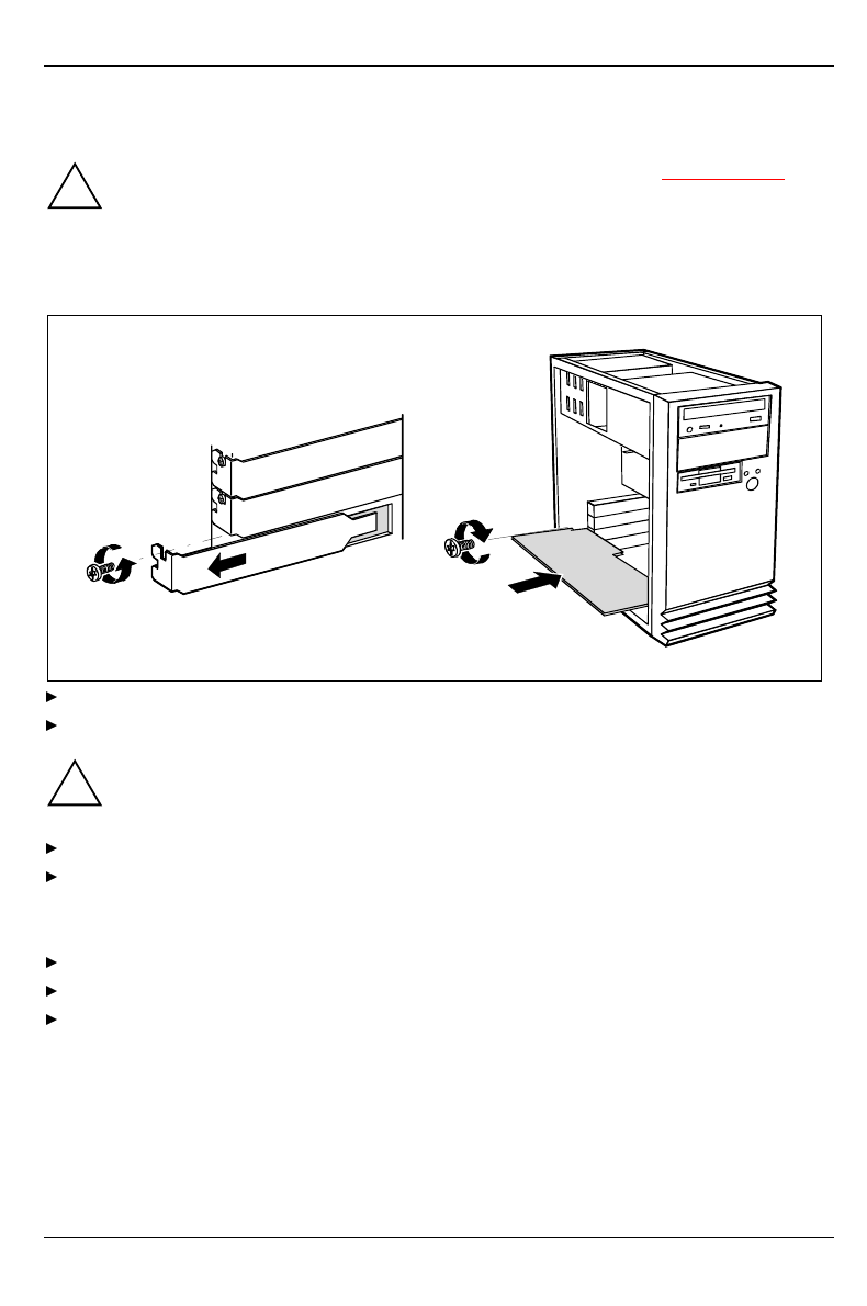
Remove the screw (1).
Remove the rear slot cover plate from the slot (2).
!Do not dispose of the rear slot cover plate. For cooling, protection against fire and in order
to comply with EMC regulations, you must refit the rear slot cover plate if you remove the
board.
Take the new board out of its packaging.
Make the required settings for the board.
Put the board in the required slot and push it carefully in place (3). Ensure that the end of a long
board without angle bracket fits into the corresponding guide of the system unit.
Press the board into the slot so that it engages.
Fix the board with the screw (4).
If necessary, plug the lines on the board.
System expansions
A26361-K515-Z100-1-7619 37
Settings in BIOS Setup
If you have installed or removed a PCI board, please check in the BIOS Setup the settings for the
relevant PCI slot. If necessary, change the settings. Further information is provided in the
documentation for the PCI board.
Memory, processor, lithium battery
Details of how and if you can upgrade the main memory or retrofit the second-level cache of your
PC are provided in the Technical Manual for the system board. Below the necessary steps are
described to enable you to work on the system board.
Open the system unit (see "Opening the system unit").
If a board is installed on the system board, you may have to remove it (see "Installing a
board").
Make desired extensions as it is described in the Technical Manual for the system board.
If you have removed a board, install it now (see "Installing a board").
Close the system unit (see "Assembling the system unit").
Replacing the lithium battery
!Incorrect replacement of the lithium battery may lead to a risk of explosion.
The lithium battery may be replaced only with an identical battery or with a type
recommended by the manufacturer.
Do not throw lithium batteries into the trashcan. It must be disposed of in accordance with
local regulations concerning special waste.
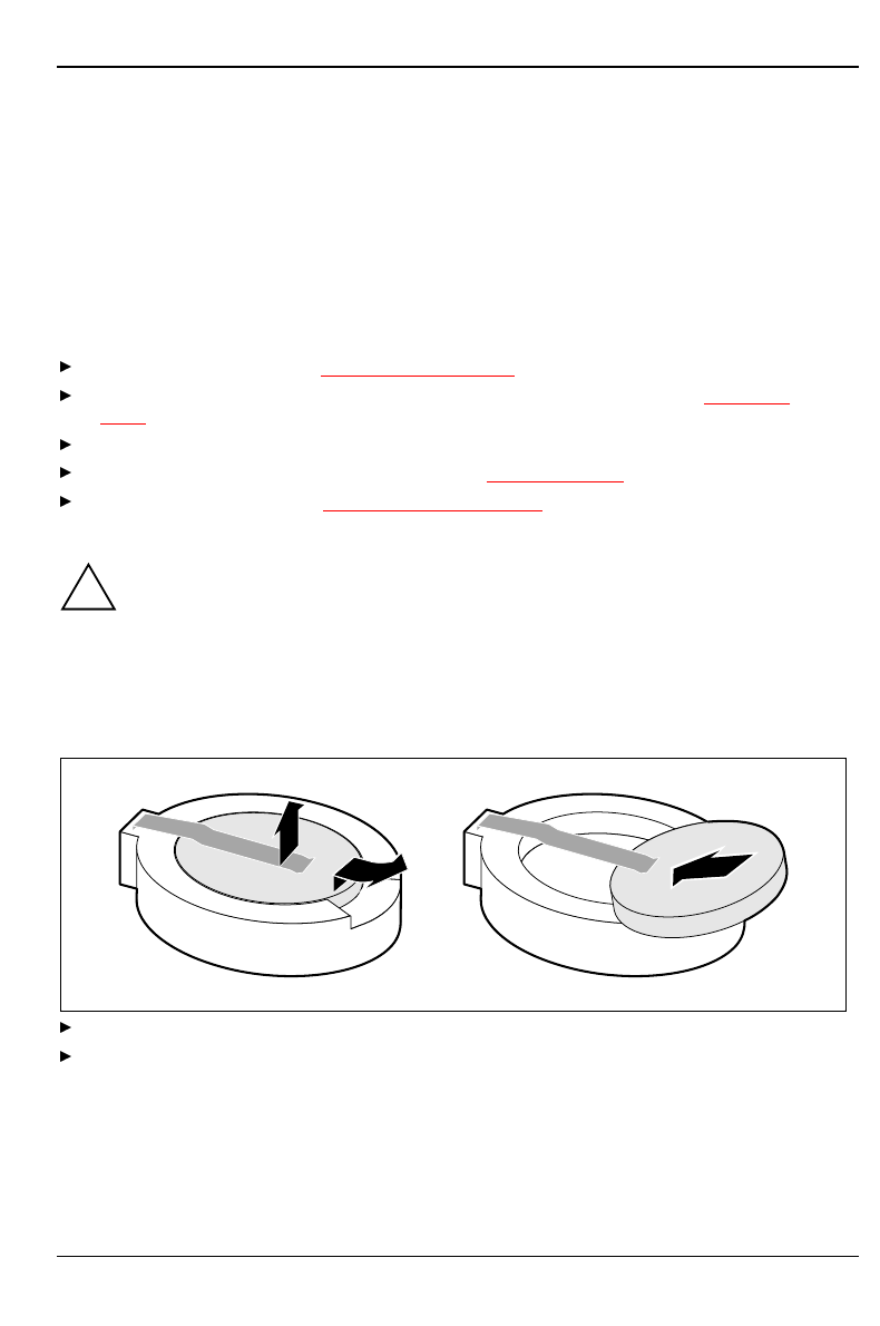
Make sure that you insert the battery the right way round. The plus pole must be on the
top!
1
23
+
++
+
Lift the contact (1) a few millimeters and remove the battery from its socket (2).
Insert a new lithium battery of the same type in the socket (3).


A26361-K515-Z100-1-7619 39
Technical data
Electrical data
Regulations complied with: EN 60950 / VDE 0805
UL 1950
CSA 22.2 No.950
Protection class: I
Rated voltage range: (selectable) 100 V to 125 V / 200 V to 240 V
Frequency: 50 Hz - 60 Hz
Max. rated current: 100 V - 125 V / 2.0 A
200 V - 240 V / 1.2 A
Maximum power draw in operation:
Minimum power draw in operation:
reduced by Windows 9x
Power management advanced_
Power draw in energy saving mode:
Power draw in the 'ready' status:
< 40 W *)
< 30 W *)
< 25 W *)
< 3 W *)
Dimensions
Width/Depth/Height:
Weight: 190 mm/350 mm/355 mm
ca. 8 kg (78.5 N) in basic configuration
Environmental conditions
Environment class 3K2
Environment class 2K2 DIN IEC 721 part 3-3
DIN IEC 721 part 3-2
Temperature:
• Operating (3K2)
• Transport (2K2) 15 °C .... 35 °C
-25 °C .... 60 °C
Condensation in operating must be avoided.
Clearance required to ensure adequate ventilation:
• left-hand side
• front
• rear
min. 200 mm
min. 200 mm
min. 200 mm
*) These values only apply for a SCENIC Edition Mi with the configuration below. When additional
components are incorporated, the power consumption in energy saving mode may exceed the
requirements for the environment symbol ("Blue Angel") (30 W).
Processor ( 512 Kbyte cache):
Main memory:
Floppy disk drive:
Hard disk drive:
Software:
CD-ROM drive
Pentium II MMX at 333 MHz
64 Mbytes
1.44 Mbytes
2.1 Gbyte
Windows 95 Power management - Advanced...
24fold
Technical data Interrupt table
40 A26361-K515-Z100-1-7619
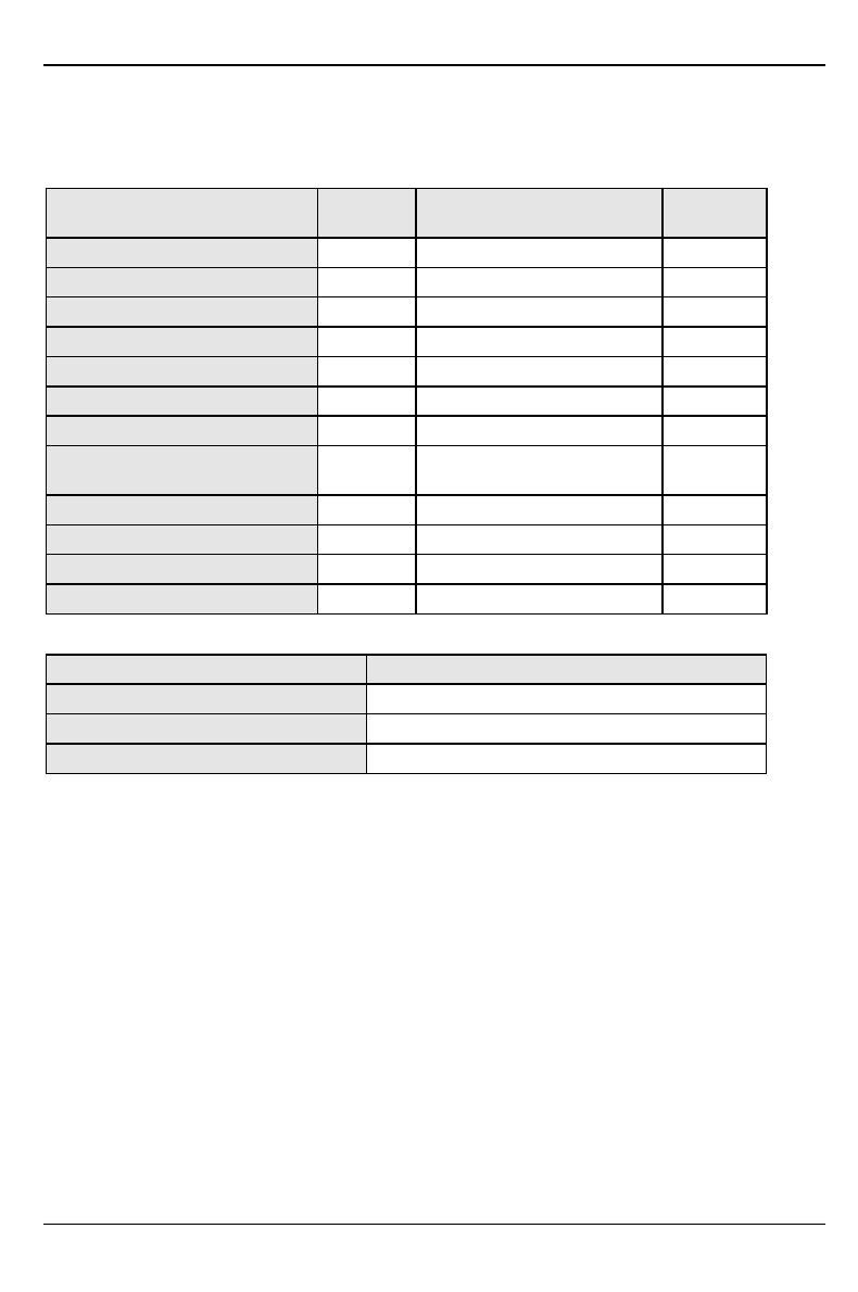
Interrupt table
Please note that an interrupt cannot be used by two applications at the same time.
Address Interrupts assigned as
shipped possible
Interrupts
Keyboard IRQ1
Serial interface COM1 03F8 IRQ4
Serial port COM 2 02F8 IRQ3
Fax/modem 03E8 IRQ5
Floppy disk drive controller IRQ6
Parallel interface LPT1 0378 IRQ7
RTC IRQ8
Audio controller assigned by the BIOS IRQ5,
IRQ7, IRQ9
Mouse controller IRQ12
Numeric processor IRQ13
IDE controller 1 IRQ14
IDE controller 2 IRQ15
DMA channels
DMAs assigned as shipped
Floppy disk drive controller DMA2
Free/ECP mode DMA3
Cascaded DMA channels DMA4

A26361-K515-Z100-1-7619 41
Index
!
2
i2
2
A
Accessible drive
installing 31
Accumulator, disposal 5
Activating, security measures 21
Address 40
Alphanumeric keypad 20
Alt Gr key 20
Assembling, PC 30
Assignment
DMA channels 40
I/O address 40
interrupt 40
Audio input 13
Audio output 13
B
Battery 37
disposal 5
replacing 37
BIOS Setup 21
security functions 21
Board
installing 36
safety 4
C
Cable
connecting 12
disconnecting 12
Cabling, PC 12
Cache
installing 37
Calculator keypad 20
CD, Windows 26
CD-ROM drive
indicator 16
installing 31
manual 27
CE certificate 5
Changing
floppy disk drive 32
lithium battery 37
Checking, rated voltage 15

Index
42 A26361-K515-Z100-1-7619
Class B Compliance Statement 6
Cleaning 9
Clearance 39
Closing the casing 30
Configuration, BIOS-Setup 21
Connecting
cables 12
devices 12
keyboard 14
monitor 14
mouse 14
parallel port 14
power voltage 15
serial port 14
to power voltage 15
Contents of delivery 11
Control key 21
Ctrl key 21
Ctrl+Alt+Del 21
Cursor control keys 20
D
Dark screen 24
Dataprotection 21
technical 39
Date, not correct 26
Devices
connecting 12
interface 13
Dimensions 39
Diskette 19
cannot be read or written 25
write-protection 19
Display
cleaning 9
Disposal 5
DMA 40
Drifting screen display 25
Drive 30
E
Electrical data 39
Electromagnetic compatibility 5
Energy saving 4
Enter key 20
Environmental conditions 39
Environmental data 39
Ergonomic, video workstation 12
Errordate 26
floppy 25
mouse 25
screen 24, 25

Index
A26361-K515-Z100-1-7619 43
system unit 23
time 26
Error message 26
ESD 4
Euro key 20
Expansion 29
External devices
connecting 12
ports 13
F
FCC statement 6
Floppy disk drive
changing 32
indicator 16
Function keys 20
G
Game port 13
Green, power-on indicator 16
Guarantee coupon booklet 11
H
Hard disk
defect 26
indicator 16
Hard disk drive
replacing 32
I
I/O address 40
IDE drives 30
Important notes 3
Indicator
power-on indicator 16
power-on indicator fails to light 23
Installing
accessible drive 31
board 36
new Software 23
Insufficient memory 27
Interfaces 13
Interrupt table 40
Italics 2
K
Key combination 20, 21
Keyboard 20
cleaning 9
connecting 14
Keyboard port 13
Keys 20

Index
44 A26361-K515-Z100-1-7619
L
LAN-port 13
Line in 13
Line out 13
Lithium battery 37
replacing 37
M
Main memory 37
Manufacturer’s notes 4
Memory, upgrading 37
Menu key 20
Microphone jack 13
Monitor
connecting 14
transporting 8
Monitor port 13
Mouse
cleaning 9
connecting 14
error 25
Mouse port 13
N
New Installation, Software 23
No screen display 24, 25
Not enough memory 27
Notational conventions 2
Noteboard 4
CE certificat 5
disposal 5
energy saving 4
important 3
manufacturer 4
power cord selecction 6
safety 3
Num Lock key 21
Numeric keypad 20
O
ON/OFF switch 16
Opening, PC 29
Operation 11
Orange, power-on indicator 16
Other manuals 27
Overview
PC 1
preparing for use 11
P
Packing material 11
Parallel interface 13
Parallel port

Index
A26361-K515-Z100-1-7619 45
connecting devices 14
PC cabling 12
cannot boot 23
cleaning 9
closing 30
connecting 12
connecting to power voltage 15
opening 29
ports 13
setting up 12
switching off 16, 18
switching on 16, 18
transporting 8
Ports, external devices 13
Power cord selecction 6
Power management 27
Power-on indicator 16
dark 23
POWERSAV.SCR 4
Preparation for use 11
overview 11
Problems 23
Processor 37
replacing 37
Property protection 21
PS/2 mouse port 13
R
Rated voltage
setting 15
Recycling 5
Reinstalling, hard disk contents 26
Replacing
hard disk drive 32
lithium battery 37
processor 37
Restoring, hard disk contents 26
Return key 20
S
Safety 3
Screen
drifting display 25
stays blank 24
Screen blanking 4
SCSI drives 30
Security function 21
Security measures 21
Select, power cord 6
Serial interface 13
Serial port
connecting devices 14
Setting

Index
46 A26361-K515-Z100-1-7619
rated voltage 15
Settings
BIOS Setup 21, 37
Setup, see BIOS Setup
Shift key 20
Software, New Installation 23
SSLAUNCH 4
Start key 20
Streamer, installing 31
Summer time 26
Surface 39
Switching off, PC 16, 18
Switching on, PC 16, 18
Symbols, explanation of 2
System expansion 29
System settings, BIOS Setup 21
System unit, see PC
T
Technical data 39
Time, not correct 26
Tips 23, 27
Transport 8
Trouble
floppy 25
mouse 25
screen 24, 25
system unit 23
Troubleshooting 23
U
Unpacking 11
Upgrading
memory 37
processor 37
Second Level-Cache 37
Upgrading the Second-level cache 37
USB, Universal Serial Bus 13
V
Ventilation area 39
VESA (DPMS) 4
Video workstation 12
W
Warm boot 21
Windows CD 26
Winter time 26
Write protection, floppy 19

A26361-K515-Z100-1-7619
Contents
Introduction......................................................................................................................................1
Notational conventions ......................................................................................................................2
Important notes................................................................................................................................3
Safety ................................................................................................................................................3
Notes on installing and removing boards ...................................................................................4
Manufacturer's notes .........................................................................................................................4
Energy saving............................................................................................................................4
Disposal and recycling...............................................................................................................5
CE certificate .............................................................................................................................5
FCC Class B Compliance Statement.........................................................................................6
Power cord selection..................................................................................................................6
For the United States and Canada.............................................................................................7
For the United Kingdom.............................................................................................................8
Transporting the PC...........................................................................................................................8
Cleaning the PC.................................................................................................................................9
Preparation for use and operation................................................................................................11
Unpacking and checking the delivery...............................................................................................11
Preparing the PC for use .................................................................................................................11
Setting up the PC ............................................................................................................................12
Connecting devices .........................................................................................................................12
Ports for external devices ........................................................................................................13
Connecting the mouse.............................................................................................................14
Connecting the keyboard .........................................................................................................14
Connecting devices with serial or parallel port .........................................................................14
Connecting the monitor to the line voltage ...............................................................................14
Connecting the PC to the line voltage..............................................................................................15
Indicators and switches ...................................................................................................................16
Switching on the PC for the first time.......................................................................................17
Switching on the PC ................................................................................................................18
Switching off the PC ................................................................................................................18
Working with floppy disks ................................................................................................................19
Keyboard .........................................................................................................................................20
Important keys and key combinations......................................................................................20
Settings in BIOS Setup....................................................................................................................21
Property and data protection............................................................................................................21
Security functions under Windows 9x ......................................................................................21
BIOS Setup security functions .................................................................................................21
Troubleshooting and tips..............................................................................................................23
Installing new software ....................................................................................................................23
Power-on indicator remains dark after you have switched on your device .......................................23
The screen stays blank....................................................................................................................24
Flickering or drifting stripes on the monitor screen...........................................................................25
No mouse pointer displayed on the screen ......................................................................................25
The floppy disk cannot be read or written ........................................................................................25
Time and/or date is not correct ........................................................................................................26
Error messages on the screen.........................................................................................................26
Restoring the hard disk contents......................................................................................................26
Restoring the hard disk contents under Windows NT...............................................................26
Tips ...............................................................................................................................................27

Contents
A26361-K515-Z100-1-7619
System expansions....................................................................................................................... 29
Opening the system unit.................................................................................................................. 29
Assembling the system unit............................................................................................................. 30
Installing and removing drives......................................................................................................... 30
Installing an accessible drive................................................................................................... 31
Replacing the hard disk or floppy disk drive ............................................................................ 32
Installing a board............................................................................................................................. 36
Memory, processor, lithium battery ................................................................................................. 37
Technical data ............................................................................................................................... 39
Interrupt table.................................................................................................................................. 40
Index .............................................................................................................................................. 41

A26361-K515-Z100-1-7619

A26361-K515-Z100-1-7619
A26361-K515-Z100-1-7619
SCENIC Edition Mi
Operating Manual
August 1998 edition
Microsoft, MS, MS-DOS, Windows and Windows NT are Trademarks of Microsoft Corporation.
VESA and DPMS are trademarks of Video Electronics Standards Association.
PS/2 is a registered trademark of International Business Machines, Inc.
Pentium is a registered trademark of Intel Corporation, USA.
All other trademarks referenced are trademarks or registered trademarks of their respective owners,
whose protected rights are acknowledged.
Copyright Siemens AG 1998
All rights, including rights of translation, reproduction by printing, copying or similar methods, even of
parts are reserved.
Offenders will be liable for damages.
All rights, including rights created by patent grant or registration of a utility model or design, are
reserved.
Delivery subject to availability. Right of technical modification reserved.