Fujitsu 2012-002-SNB Concentrator / Relay Equipment (Networking Product) User Manual ver1 3x
Fujitsu Limited Concentrator / Relay Equipment (Networking Product) ver1 3x
Fujitsu >
User Manual

User manual
1/12
Ver 1.3
User manual
User manualUser manual
User manual

User manual
2/12
Change history
Change historyChange history
Change history
revision Updated date
summary
1.0 Sep 14 2012 First edition
1.1 Sep 24 2012 Correction of erroneous description
1.2 Sep 25 2012 Correction of erroneous description(5.6 / 5.7)
1.3 Dec 05 2012 Addition of the AC input frequency(1,3.1,4.1)

User manual
3/12
Table of contents
Table of contentsTable of contents
Table of contents
1.
Application ...................................................................................................................................... 4
2.
System Configuration ..................................................................................................................... 4
3.
Description of GW/Rep................................................................................................................... 5
3.1
Overview .................................................................................................................................... 5
3.2
Operating Range ........................................................................................................................ 5
3.3
Antenna Specifications ............................................................................................................... 5
4.
Description of Internal components ................................................................................................ 6
4.1
Overview .................................................................................................................................... 6
4.1.1
NIC board ................................................................................................................................ 7
4.1.2
Power board ............................................................................................................................ 8
4.1.3
Heater board ........................................................................................................................... 8
4.1.4
LED board ............................................................................................................................... 9
4.1.6
WIFI module ..........................................................................................................................10
5.
Required FCC and IC statement ( Host ) .....................................................................................11
5.1
FCC §15.21 ..............................................................................................................................11
5.2
FCC §15.105 ............................................................................................................................11
5.3
RSS-Gen §7.1.2. ......................................................................................................................11
5.4
RSS-Gen §7.1.3. ......................................................................................................................11
5.5
Indicating safe separation distance warning ............................................................................12
5.6
Indicating compliance with ICES-003 ......................................................................................12
5.7
Indicating compliance with 10402A-12002SNB .......................................................................12
User manual
4/12
1. Application
This document shows the description of concentrator (CN) and relay equipment(RE)
No.
Equipment name Equipment number remarks
1
relay equipment
YA14A75-B310 Input voltage:120VAC 60Hz
2 concentrator YA14A75-B311
3
relay equipment
YA14A75-B312 Input voltage:240VAC 60Hz
4 concentrator YA14A75-B313
2. System Configuration
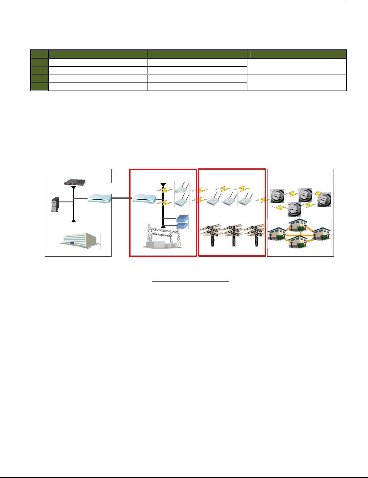
Fig2-1 is general system configuration.
Installed meters in each house is communicated to Center via RE and CN and control the meter-reading
value etc. automatically.
This equipment must be professionally installed.
Red line of Fig.2-1 is the applicable scope of this document.
Fig2-1 System configuration
Substation
Poles
Houses
…..
Center
Server
-
DHCP Server
Router
Router
Fiber-opt
network
Relay equipment
Switch
Meters
Concentrator
User manual
5/12
3. Description of GW/Rep
3.1 Overview
Form and overview of CN and RE are as shown below.
Category
equipment
Remark
CN
RE
Input voltage
Frequency 120VAC or 240VAC/60Hz Same as on the left
The makeup of RE is same as GE.
The differences are only installed
software.
operational
temperature range
-40℃~70℃
enclosure
Refer to Fig.3-1
Antenna
Refer to Fig.3-2
AC cable
Refer to Fig.3-3
RE and CN difference of firmware are as below.
Category
equipment
Remark
CN
RE
Inter
-
Server
communication applicable NA IEEE802.11n
RE
-
RE/GW
communication applicable applicable IEEE802.11n
Meter
communication applicable applicable IEEE802.11b
Relay function
NA applicable Application
3.2 Operating Range
• Voltage : ±20%
• Temperature : -40°C through +70°C
• Typical Starting Watts : <=4.7Watts (Input voltage:120VAC/240VAC)
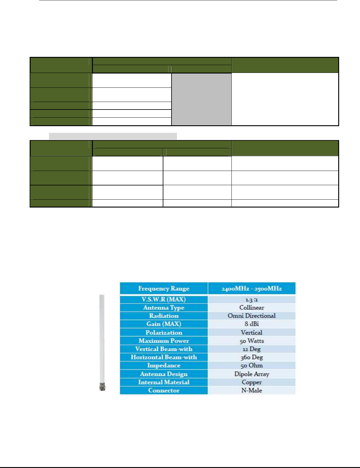
3.3 Antenna Specifications
AOA-2408M
User manual
6/12
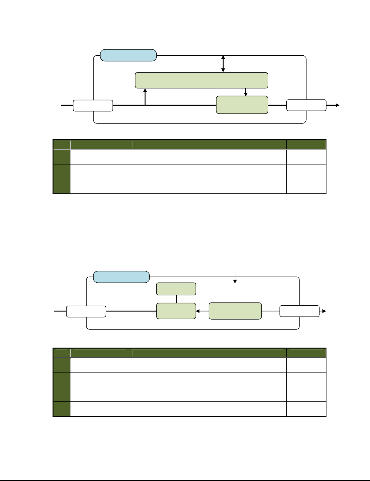
4. Description of Internal components
4.1 Overview
The CN/RE is composed of 4 board(NIC board / power board / heater board / LED board) and
AC/DC power supply.
60Hz
No.
component
summary remark
1
NIC board Wireless specification
・IEEE 802.11b/n (20MHz)
・Transmission power:210mW
・Modulation :DSSS(DBPSK)・OFDM
・Data Rate :
- for CN and RE : IEEE 802.11n, 26Mbps (fixed)
- for CN and RE (broadcast) : IEEE 802.11n, 6.5Mbps (fixed)
-For RE (communication with meter)
: IEEE 802.11b, 1Mbps (fixed)
2
Power board ・power feeding for NIC board.
- Input:24VDC / Output:4.2VDC
・Supervision of AC
power discontinuity.
3
Heater board ・
guarantee of working in cool environment(-40℃~).
4
LED board extinction power off or no service
(reset / start-up firmware) LED(gre
en)
blinking No operation ( no communication)
lighting normal operation
extinction normal LED(ora
nge)
blinking Tamper detection or boot error
lighting NIC(Cipher/Decipher element) fault
unused LED(Re
d)
5 Power supply
*AC cable is connected to this element.
*This element steps down AC input(120V/240V) to +24VDC.
* Power consumption:
- Input : 120V/240VAC(60Hz) – 80W(max),5.0W(ave)
- Output : 24VDC – 40W(max),5.0W(ave)
6 Antenna 2.4~2.5GHz 8dBi mesh omni antenna
External antenna
CN / RE
LED
board
From electric pole
120VAC
/
240VAC
120VAC
/ 240VAC
60Hz
+24
V
D
C
etc.
Power
board
Heater board
+24
V
D
C
Power
Supply
NIC board
②
①
①
① ferrite core
Equivalent of
KGS : GRFC-10
② ferrite core
Equivalent of
Seiwa:E04SR301334
User manual
7/12
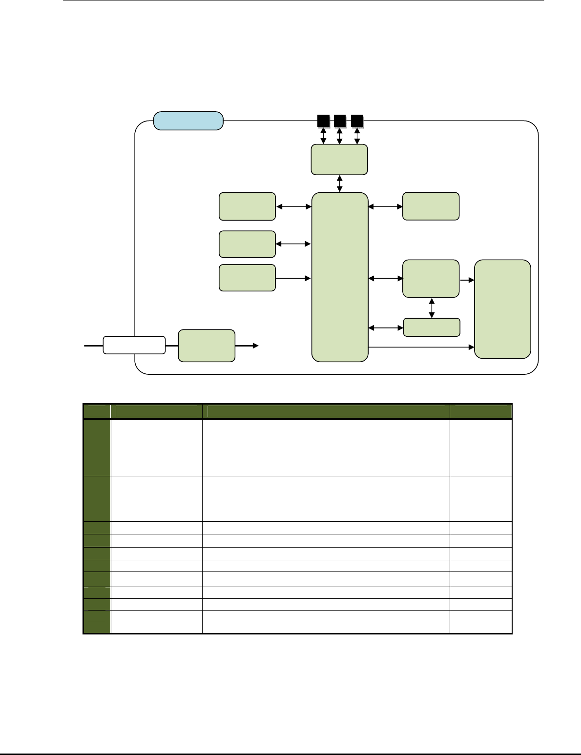
4.1.1 NIC board
Major elements of NIC board are as shown below.
Details of the element of NIC board are as shown below.
No.
element summary remark
1
WIFI module MAC/baseband/radio and wireless access point.
IEEE802.11b/n 3x3 MIMO
- reference clock – 100MHz(PCI Express Interface)
- 3.3V – for main element
- 4.2V – for power amp
2
Cipher / decipher
control This element handles cipher/decipher processing by
using fixed key.
And, target information are time information come from
wireless and program use internal process.
3
CPU 32bit processor / 400MHz
4
Program memory Stored the program of ADHOC
5
Work memory Work memory
6
GbE Unused
7
JTAGs For program writing.
8
RESET Power on reset / reset switch
LEDs Equipment status indication refer to table of 4.1
9
Power element This element convert 4.5VDC to 3.3V power supply
for internal use.
Operating range : Same as chapter 3.2.
3.3VDC
for internal use
NIC board
connector
From
power board
4
.2
V
D
C
CPU
Power
element
Cipher /
decipher
control
WIFI
module
Program
memory
LEDs
JTAGs
GbE
RESET
Work
memory
User manual
8/12
4.1.2 Power board
Major elements of power board are as shown below..
Details of the element of NIC board are as shown below.
No.
element summary remark
1
Battery control
- external battery charge/discharge control.
- temperature monitoring of battery box. unused
2
Voltage
down converter - Diode bridge for detecting 12V/24V.
- This element convert 12/24VDC to 4.2V power supply
for NIC board.
Operating range : Same as chapter 3.2.
4.1.3 Heater board
Major elements of heater board are as shown below..
Details of the element of heater board are as shown below.
No.
element summary remark
1
Temperature
monitoring temperature monitoring of wireless board.
2
Heater control Heater control element observes the state of
temperature monitoring element, and guarantees
operating temperature of the equipment by energizing
to the heater at the low temperature.
3
heater
Use of cement resistor
4
Operating range : Same as chapter 3.2.
To power board
Abnormal
temperature
detection
From
power line
120/240VAC
Heater board
connector
From Power supply
24VDC
heater
Heater
control
Temperature
monitoring
connector
12VDC
From / To battery box
(unused)
From
power supply
24VDC
Power board
connector
Battery control
connector
To NIC board
4.2VDC
Voltage
Up converter
User manual
9/12
4.1.4 LED board
Major elements of LED board are as follows.
Details of the element of NIC board are shown below.
No.
element summary remark
1
LED(Green) Refer to table of 4.1. RUN
2
LED(Red) AL0
3
LED(Orange) AL1
Operating range : Same as chapter 3.2.
4.1.5 Power supply
AC power supply mounted to this equipment is a marketed product.
Specification of power supply are as shown below.
No.
category summary
1 Max output wattage (W) 60W
2
Input
voltage 85-265 VAC
3 Frequency(Hz) 47-63Hz
4 Current (Full road) 2A max (115VAC) / 1A max (230VAC)
5 Inrush current (<2ms) 30 A max (115VAC) / 50A max (230VAC)
6 Leakage current 0.5mA max
7
output
Voltage (VDC) 24V
8 Voltage accuracy ±2%
9 Current(mA) max 2500
10
ripple <0.2% volt +40mV max(V
p-p
)
11
noise <0.5% volt +50mV max(V
p-p
)
12
Efficiency (at 230V) 86%
13
Switching frequency 100KHz
Operating range : Same as chapter 3.2.
From
NMI board
Control signals
& ground
LED board
connector
LED(Orange)
LED(Green)
LED(Red)
User manual
10/12
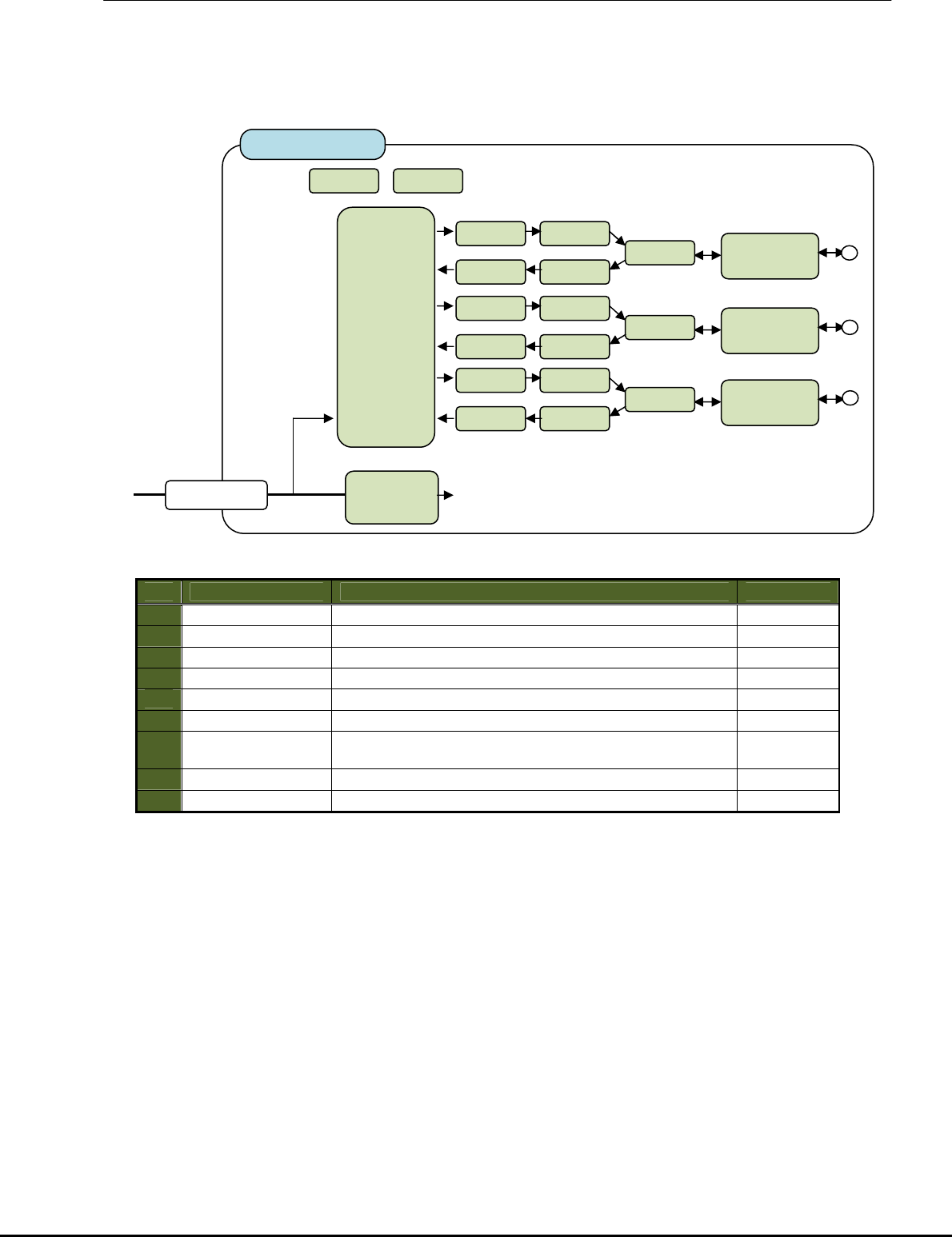
4.1.6 WIFI module
Major elements of WIFI module are as follows.
Details of the element of WIFI module are shown below.
No.
element summary remark
1
WRAN Chip 3x3 Spatial Stream MIMO WLAN Radio Chip
2
Balun Balanced to unbalanced
3
PA Power amplifiers
4
LNA Low noise amplifiers
5
SW RF Switch
6
Filter Antenna RF Band pass filter
7
Power element This element convert 3.3VDC to 1.2V power supply
for internal use.
8
ROM MAC Configuration TOP Memory
9
TXCO Temperature Compensated Crystal Oscillator
Operating range : Same as chapter 3.2.
PCI Express
Interface
(VCC_4.2V)
(VDD_3.3V)
WIFI module
connector
Filter
Antenna 0
SW
PA
LNA
Balun
Balun
Filter
Antenna 1
SW
PA
LNA
Balun
Balun
Filter
Antenna 2
SW
PA
LNA
Balun
Balun
WLAN
Chip
1.2VDC
for internal use
Power
element
VDD 3.3V
VCC 4.2V
TXCO
ROM

User manual
11/12
5. Required FCC and IC statement ( Host )
This device complies with Part 15 of the FCC Rules. Operation is subject to the following two conditions:
(1) this device may not cause harmful interference, and
(2) this device must accept any interference received, including
interference that may cause undesired operation.
5.1 FCC §15.21
Changes or modifications not expressly approved by the party responsible for compliance could void
the user’s authority to operate the equipment.
5.2 FCC §15.105
For class B equipment:
NOTE:
This equipment has been tested and found to comply with the limits for a Class B digital device, pursuant
to part 15 of the FCC Rules. These limits are designed to provide reasonable protection against harmful
interference in a residential installation. This equipment generates, uses and can radiate radio frequency
energy and, if not installed and used in accordance with the instructions, may cause harmful interference
to radio communications. However, there is no guarantee that interference will not occur in a particular
installation. If this equipment does cause harmful interference to radio or television reception, which can
be determined by turning the equipment off and on, the user is encouraged to try to correct the
interference by one or more of the following measures:
— Reorient or relocate the receiving antenna.
— Increase the separation between the equipment and receiver.
— Connect the equipment into an outlet on a circuit different from that to which the receiver is connected.
— Consult the dealer or an experienced radio/TV technician for help.
5.3 RSS-Gen §7.1.2.
Under Industry Canada regulations, this radio transmitter may only operate using an antenna of a type
and maximum (or lesser) gain approved for the transmitter by Industry Canada. To reduce potential radio
interference to other users, the antenna type and its gain should be so chosen that the equivalent
isotropically radiated power (e.i.r.p.) is not more than that necessary for successful communication.
Conformément à la réglementation d'Industrie Canada, le présent émetteur radio peut fonctionner avec
une antenne d'un type et d'un gain maximal (ou inférieur) approuvé pour l'émetteur par Industrie Canada.
Dans le but de réduire les risques de brouillage radioélectrique à l'intention des autres utilisateurs, il faut
choisir le type d'antenne et son gain de sorte que la puissance isotrope rayonnée équivalente (p.i.r.e.) ne
dépasse pas l'intensité nécessaire à l'établissement d'une communication satisfaisante.
5.4 RSS-Gen §7.1.3.
This device complies with Industry Canada licence-exempt RSS standard(s). Operation is subject to the
following two conditions:
(1) this device may not cause interference, and
(2) this device must accept any interference, including interference that may cause undesired operation
of the device.
Le présent appareil est conforme aux CNR d'Industrie Canada applicables aux appareils radio exempts
de licence. L'exploitation est autorisée aux deux conditions suivantes:
(1) l'appareil ne doit pas produire de brouillage, et
(2) l'utilisateur de l'appareil doit accepter tout brouillage radioélectrique subi, même si le brouillage est
susceptible d'en compromettre le fonctionnement.

User manual
12/12
5.5 Indicating safe separation distance warning
This equipment complies with radio frequency exposure limits set forth by the FCC and Industry
Canada for an uncontrolled environment. This equipment should be installed and operated with a
Minimum distance of 20cm between the device and the user or bystanders. This device must
Not be co-located or operating in conjunction with any other antenna or transmitter.
Cet équipement est conforme aux limites d'exposition aux radiofréquences définies par la FCC et
Industrie Canada pour un environnement non contrôlé. Cet équipement doit être installé et utilisé avec
un minimum de 20 cm de distance entre le dispositif et l'utilisateur ou des tiers. Ce dispositif ne doit pas
être utilisé a proximité d’une autre antenne ou d’un autre émetteur.
5.6 Indicating compliance with ICES-003
This Class B digital apparatus complies with Canadian ICES-003.
Cet appareil numérique de la classe B est conforme à la norme NMB-003 du Canada.
5.7 Indicating compliance with RSS-Gen §7.1.2.
This radio transmitter IC: 10402A-12002SNB has been approved by Industry Canada to operate with the
antenna types listed below with the maximum permissible gain and required antenna impedance for each
antenna type indicated. Antenna types not included in this list, having a gain greater than the maximum
gain indicated for that type, are strictly prohibited for use with this device..
Antenna type: collinear antenna, gain: 8 dBi, impedance: 50 ohm
Le présent émetteur radio IC: 10402A-12002SNB a été approuvé par Industrie Canada pour fonctionner
avec les types d'antenne énumérés ci-dessous et ayant un gain admissible maximal et l'impédance
requise pour chaque type d'antenne. Les types d'antenne non inclus dans cette liste, ou dont le gain est
supérieur au gain maximal indiqué, sont strictement interdits pour l'exploitation de l'émetteur.
Type d’antenne: antenne colinéaire, gain: 8 dBi, impédance : 50 ohm