Fujitsu Fi 4640S Users Manual
2015-01-25
: Fujitsu Fujitsu-Fi-4640S-Users-Manual-219219 fujitsu-fi-4640s-users-manual-219219 fujitsu pdf
Open the PDF directly: View PDF ![]() .
.
Page Count: 92
- Revisions, Disclaimers
- Fujitsu Offices
- Note, Liability
- Preface
- Conventions
- Contents
- Chapter Index
- Chapter 1 Components
- Chapter 2 Installation and Connections
- Chapter 3 Operating Instruction
- Chapter 4 ADF Document Specification
- Chapter 5 Scanner Specifications
- Chapter 6 Consumables and Options
- Chapter 7 Setup Mode
- Activating the Setup Mode
- Contents of the Setup Mode
- 1. Setting double feed detection (Paper Thickness)
- 2. Setting double feed detection (Paper Length)
- 3. Setting IPC pre-set mode
- 4. Reset of the abrasion counter
- 5. Setting the pick start time
- 6. Setting the time-out limit
- 7. ADF Offset Setting
- 8. Flatbed Offset Setting
- 9. Option (IPC/Imprinter) Status Display
- 10. SCSI ID Setting
- 11. SCSI Terminator Setting
- 12. Low Power Mode Setting
- 13. Select Interface
- 14. Display the TPS Board ID Number
- 15. Select Built-In/IPC-4D Image Processing
- 16. Adjust ADF Erasing Edges
- 17. Adjust FB Erasing Edges
- 18. Reset of the Ink Remain Counter
- 19. Setting the Numbering Print Function (for fi-475PR Imprinter Option)
- Glossary of Terms
- Index
Operator's Guide
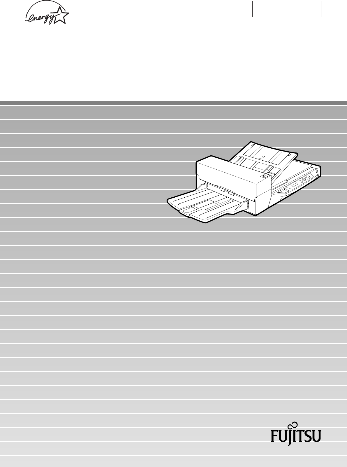
fi-4640S Image Scanner
C150-E209-01EN
fi-4640S
Image Scanner
Operator's Guide
i
Revisions, Disclaimers
FCC declaration: This equipment has been tested and found to comply with the
limits for a Class B digital device, pursuant to Part 15 of the FCC Rules. These
limits are designed to provide reasonable protection against harmful interference in
a residential installation. This equipment generates, uses, and can radiate radio
frequency energy and, if not installed and used in accordance with the instruction
manual, may cause harmful interference to radio communications. However, there
is no guarantee that interference will not occur in a particular installation. If this
equipment does cause harmful interference to radio or television reception, which
can be determined by turning the equipment off and on, the user is encouraged to
try to correct the interference by one or more of the following measures:
• Reorient or relocate the receiving antenna.
• Increase the separation between the equipment and receiver.
• Connect the equipment into an outlet on a circuit different from that to which the
receiver is connected.
• Consult the dealer or an experienced radio/TV technician for help.
FCC warning: Changes or modifications not expressly approved by the party
responsible for compliance could void the user's authority to operate the equipment.
NOTICE
• The use of a non-shielded interface cable with the referenced device is prohibited.
The length of the parallel interface cable must be 3 meters (10 feet) or less. The
length of the serial interface cable must be 15 meters (50 feet) or less.
• The length of the power cord must be 3 meters (10 feet) or less.
Edition Date published Revised contents
01 July, 2001 First edition
Specification No. C150-E209-01EN

ii
This Class B digital apparatus complies with Canadian ICES-003.
Cet appareil numérique de la classe B est conformme à la norme NMB-003 du
Canada.
High Safety Required Use: The Product is designed, developed and manufactured
as contemplated foe general use, including without limitation, general office use,
personal use and household use, but is not designed, developed and manufactured
as contemplated for use accompanying fatal risks or dangers that, unless ex-
tremely high safety is secured, could lead directly to death, personal injury, severe
physical damage or other loss (hereinafter "High Safety Required Use"), including
without limitation, nuclear power core control, airplane control, air traffic control,
mass transport operation control, life support, weapon launching control. The
Customer shall not use the Product without securing the sufficient safety required
for the High Safety Required Use. In addition, Fujitsu (or other affiliate's name)
shall not be liable against the Customer and/or any third party for any claims or
damages arising in connection with the High Safety Required Use by the Customer
of the Product.
As an ENERGYSTAR ® Partner, Fujitsu Limited has determined that this scanner meets
ENERGYSTAR ® guidelines for energy efficiency. ENERGYSTAR ® is a
U. S. registered mark.
The contents of this manual may be revised without prior notice.
All Rights Reserved, Copyright © 2001 FUJITSU LIMITED.
Printed in Japan.
No part of this manual may be reproduced in any form without permission.

iii
Fujitsu Offices
Please send your comments on this manual or on Fujitsu products to the following
addresses:
FUJITSU COMPUTER PRODUCTS OF
AMERICA,INC.
2904 Orchard Parkway,San Jose.
California 95134-2022,U.S.A.
TEL:1-408-432-6333
FAX:1-408-432-3908
http://www.fcpa.com/
FUJITSU AUSTRALIA LIMITED
Fujitsu Hause 2 Julius Avenue North Ryde
N.S.W 2113 AUSTRALIA
TEL:61-2-9776-4555
FAX:61-2-9776-4019
http://www.fujitsu.com.au/
FUJITSU CANADA,INC.
2800 Matheson Blvd.East,Mississauga.
Ontario L4W 4X5,CANADA
TEL:1-905-602-5454
FAX:1-905-602-5457
http://www.fujitsu.ca/
FUJITSU DEUTSCHLAND GmbH.
Frankfurter Ring 211,
8000 München 40,F.R,GERMANY
TEL:49-89-32378-0
FAX:49-89-32378-100
http://www.fujitsu.de/
FUJITSU ESPAÑA,S.A
Edificio torre Europa 5a
Paseo de la Castellana 95
Madrid 28046,SPAIN
TEL:34-1-581-8000
FAX:34-1-581-8300
http://www.fujitsu-europe.com/home/
FUJITSU EUROPE LTD.
2,Longwalk Road,Stockey Park,Uxbridge
Middlesex,UB11 1AB,U.K
TEL:44-81-573-4444
FAX:44-81-573-2643
http://www.fujitsu-europe.com/home
FUJITSU FRANCE S.A.
I, Place des Etats-Unis, SILIC 310,
94588 Rungis cedex, FRANCE
TEL:33-1-4180-3880
FAX:33-1-4180-3866
http://www.fujitsu-europe.com/home/
FUJITSU COMPUTERS (SINGAPORE) PTE,
LTD.
20 Science Park Road #03-01, Tele Teck Park
Singapore Science Park II, Singapore 117674
Republic of Singapore
TEL:65-777-6577
FAX:65-771-5669
http://www.fujitsu-computers.com.sg/
FUJITSU HONG KONG Limited
10/F, Lincoln House, Taikoo Place,
979 King’s Road, Island East, Hong Kong
TEL:852-827-5780
FAX:852-827-4724
TLX:62667
http://www.fujitsu.com.hk/
FUJITSU ITALIA S.p.A.
Via Nazario Sauro, 38
20099 Sestos, Giovanni (MI), ITALY
TEL:39-2-26294-1
FAX:39-2-26294-201
http://www.fujitsu-europe.com/home
FUJITSU NORDIC AB
Kung Hans väg,S-192 68 Sollentuna, SWEDEN
TEL:46-8-626-4500
FAX:46-8-626-4588
http://www.fujitsu-europe.com/home
FUJITSU LIMITED
International Operations
Marunouchi 1-6-1, Chiyoda-ku,
Tokyo 100 JAPAN
TEL:(81-3)3216-3211
FAX:(81-3)3213-7174
TLX:J2283
Cable:”FUJITSU LIMITED TOKYO”
http://www.fujitsu.co.jp/

iv
Note, Liability
READ ALL OF THIS MANUAL CAREFULLY BEFORE USING THIS PRODUCT. IF
NOT USED CORRECTLY, UNEXPECTED INJURY MAY BE CAUSED TO USERS
OR BYSTANDERS.
While all efforts have been made to ensure the accuracy of all information in this
manual, FUJITSU assumes no liability to any party for any damage caused by
errors or omissions or by statements of any kind in this manual, its updates or
supplements, whether such errors are omissions or statements resulting from
negligence, accidents, or any other cause. FUJITSU further assumes no liability
arising from the application or use of any product or system described herein; nor
any liability for incidental or consequential damages arising from the use of this
manual. FUJITSU disclaims all warranties regarding the information contained
herein, whether expressed, implied, or statutory.
FUJITSU reserves the right to make changes to any products herein, to improve
reliability, function, or design, without further notice and without obligation.

v
Preface
This manual explains how to use the fi-4640S image scanner.
This manual contains chapters on the following topics:
COMPONENTS
INSTALLATION AND CONNECTIONS
OPERATING INSTRUCTIONS
ADF DOCUMENT SPECIFICATIONS
SCANNER SPECFICATIONS
CONSUMABLES AND OPTIONS
SETUP MODE
It also contains a Glossary of Terms and an Index.
Refer to the Cleaning and Maintenance Guide for information about the routine
operation of the fi-4640S.
The Cleaning and Maintenance Guide contains chapters on OPERATING IN-
STRUCTIONS, CLEANING, REPLACEMENT OF PARTS, ADJUSTMENT and
TROUBLESHOOTING.
The fi-4640S is a very fast and highly functional image scanner developed for high
quality image processing, using charge-coupled device (CCD) image sensors. This
scanner features high-speed simplex scanning with an automatic document feeder
(ADF).

vi
Conventions
Important information that requires special attention is indicated as follows:
WARNING
WARNING indicates that serious personal injury may result if you do not follow a
procedure correctly.
CAUTION
CAUTION indicates that minor personal injury, loss of data, or damage to the
scanner may result if you do not follow a procedure correctly.
Official Fujitsu part names are indicated with an initial capital letter, as in the part
name “Pick roller”.
NOTICE
A NOTICE provides “how-to” tips or suggestions to help you perform a procedure
correctly.

viivii
CONTENTS
❑❑
❑❑
❑CHAPTER 1 COMPONENTS
Checking the Components ................................................................................... 1-1
Units and Assemblies .......................................................................................... 1-2
Operator Panel ..................................................................................................... 1-5
❑❑
❑❑
❑CHAPTER 2 INSTALLATION AND CONNECTIONS
Precautions .......................................................................................................... 2-1
Inspection ............................................................................................................ 2-2
Repositioning the Shipping Lock .......................................................................... 2-3
Cable Connections ............................................................................................... 2-4
Mounting the Stacker ........................................................................................... 2-6
Setting the SCSI ID and the SCSI Terminator ...................................................... 2-7
❑❑
❑❑
❑CHAPTER 3 OPERATING INSTRUCTION
Turning the Power On ........................................................................................... 3-1
Waking up the Scanner from the Low Power Mode ............................................... 3-2
Manual Feed Mode Setting................................................................................... 3-3
Loading Documents on the ADF........................................................................... 3-4
Loading Documents on the Flatbed ...................................................................... 3-8
Loading Documents Larger than the Document Bed............................................. 3-9
Reading a Page from a Thick Book .................................................................... 3-10
❑❑
❑❑
❑CHAPTER 4 ADF DOCUMENT SPECIFICATION
Document Size..................................................................................................... 4-1
Document Quality................................................................................................. 4-2
ADF Document Feeder Capacity .......................................................................... 4-4
Areas not to be Perforated ................................................................................... 4-5
Grounding Color Areas ......................................................................................... 4-6
Double Feed Detection Condition ......................................................................... 4-7
Job Separation Sheet ........................................................................................... 4-8
❑❑
❑❑
❑CHAPTER 5 SCANNER SPECIFICATIONS
Basic Product Specification ................................................................................. 5-1
Installation Specification ...................................................................................... 5-2
Dimensions .......................................................................................................... 5-3
❑❑
❑❑
❑CHAPTER 6 CONSUMABLES AND OPTIONS
Consumables List................................................................................................. 6-1
Options List.......................................................................................................... 6-2
Video Interface Board Option ............................................................................... 6-3
IPC-4D Option ...................................................................................................... 6-7
fi-475PR Option (Imprinter)................................................................................... 6-8
❑❑
❑❑
❑CHAPTER 7 SETUP MODE
Activating the Setup Mode ................................................................................... 7-1
Contents of the Setup Mode................................................................................. 7-2
❑❑
❑❑
❑GLOSSARY OF TERMS ............................................................................. GL-1
❑❑
❑❑
❑INDEX ........................................................................................................... IN-1
viii

ix
COMPONENTS
INSTALLATION
AND
CONNECTIONS
OPERATING
INSTRUCTION
DOCUMENT
SPECIFICATION
SCANNER
SPECIFICATIONS
CONSUMABLES
AND
OPTIONS
SETUP
MODE
GLOSSARY
OF
TERMS
INDEX
COMPONENTS
INSTALLATION AND
CONNECTIONS
OPERATING
INSTRUCTION
DOCUMENT
SPECIFICATION
SCANNER
SPECIFICATIONS
CONSUMABLES
AND OPTIONS
SETUP MODE
GLOSSARY
OF TERMS
INDEX

1
CHAPTER
COMPONENTS
This chapter describes the components of the scanner, part names, operator
panel arrangement, and the function of parts and LED indicators. After unpack-
ing the scanner, confirm that all components have been received by checking
them against the list in the first section.
Checking the Components
Units and Assemblies
Operator Panel
1-1
1
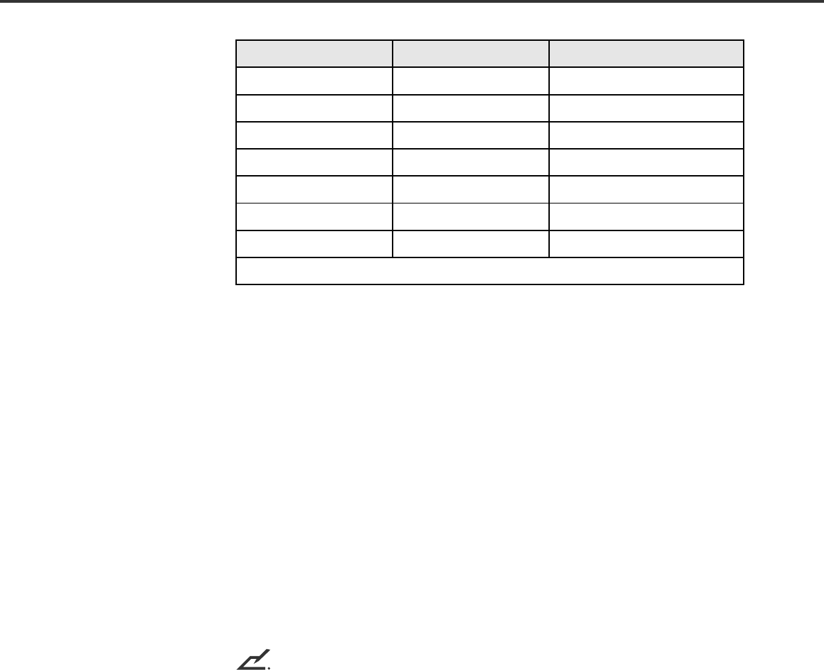
Checking the Components
These high precision components must be handled carefully.
Confirm that all the components shown in the following figure have been received.
If any component is missing, please contact your sales agent.
Manuals and Drivers
Scanner Power cable
for North America Power cable
for Europe
Pad ASY
NOTICE
One CD-ROM (User’s Manual) contains ”Cleaning and Maintenance” and this manual. The other CD-ROM
contains scanner drivers.
1-2
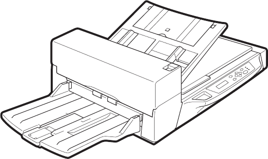
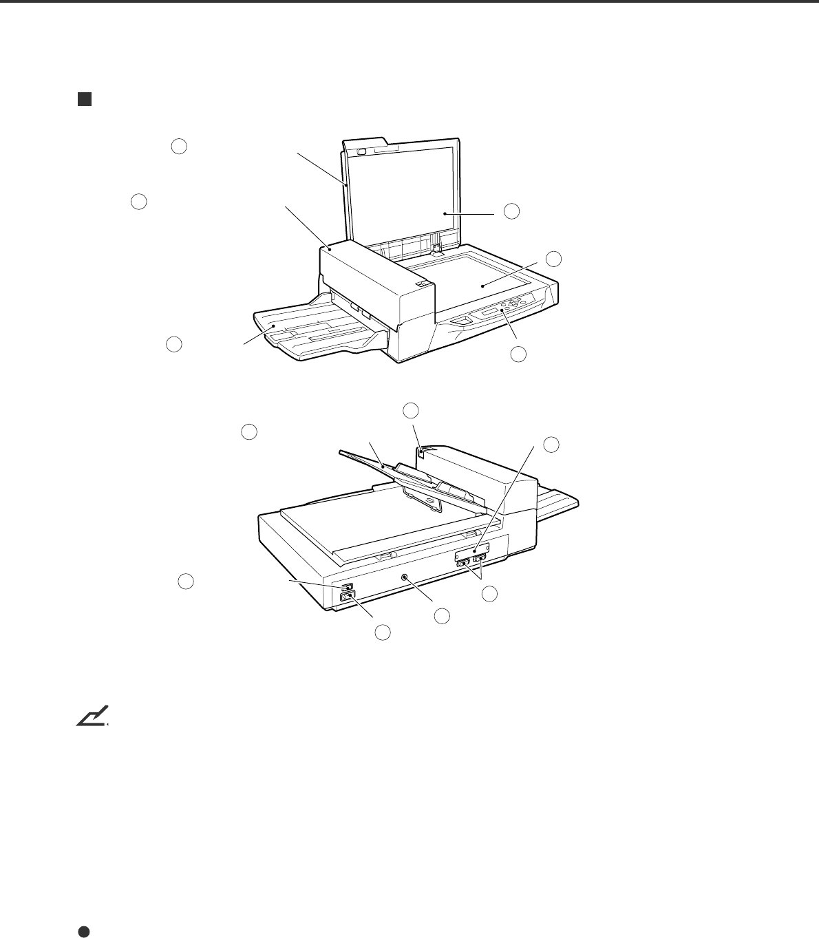
Units and Assemblies
This section shows the exterior view and assemblies of the scanner. This section also provides the name
of each part and describes its functions.
Units
NOTICE
The shipping lock must be switched to the operating position before the scanner can be used. Refer to
page 2-3.
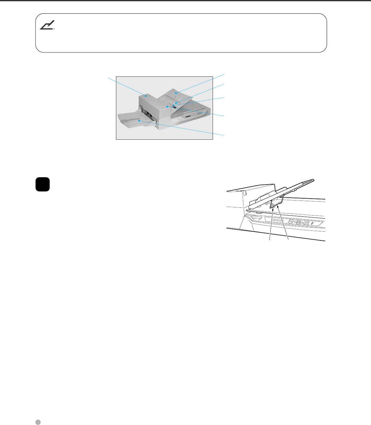
fi-4640S
Document cover
1
Document bed
2
Document holding pad
3
Power switch
6
Operator panel
7
Stacker
5
ADF paper chute
8
ADF lever
9
Interface connector
11
Power inlet
10
Automatic document
feeder (ADF)
4
EXT connector
12
Option board slot
(Third party slot)
13

1-3
No.Part Function
1 Document cover Closes over and keeps in place the document to be
read.
2 Document bed Holds document to be read. Also called Flatbed (FB).
3 Document holding pad Presses document to the Document bed.
4Automatic document feeder
(ADF) Automatically feeds documents to the reading
position.
5 Stacker Stacks the read documents.
6 Power switch Turns the power On or Off.
7 Operator panel Contains indicator panel that indicates scanner status.
8 ADF paper chute Holds the documents to be fed by the automatic
document feeder (ADF).
9ADF lever Opens/closes the ADF to enable the removal of
documents jammed in the feeder.
10 Power inlet Connects to an AC power outlet with the power cable.
11 Interface connectors Connect to the host system with interface cables.
12 EXT connector Connects to an optional imprinter.
13 Option board slot
(Third party slot) An option board is installed.
1-4
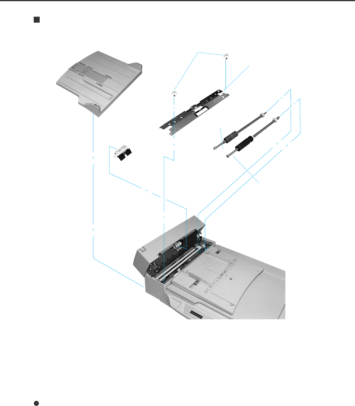
Stacker
Thumb screw
Guide A ASY
Pick roller 2
Pick roller 1
Pad ASY
Assemblies
1-5
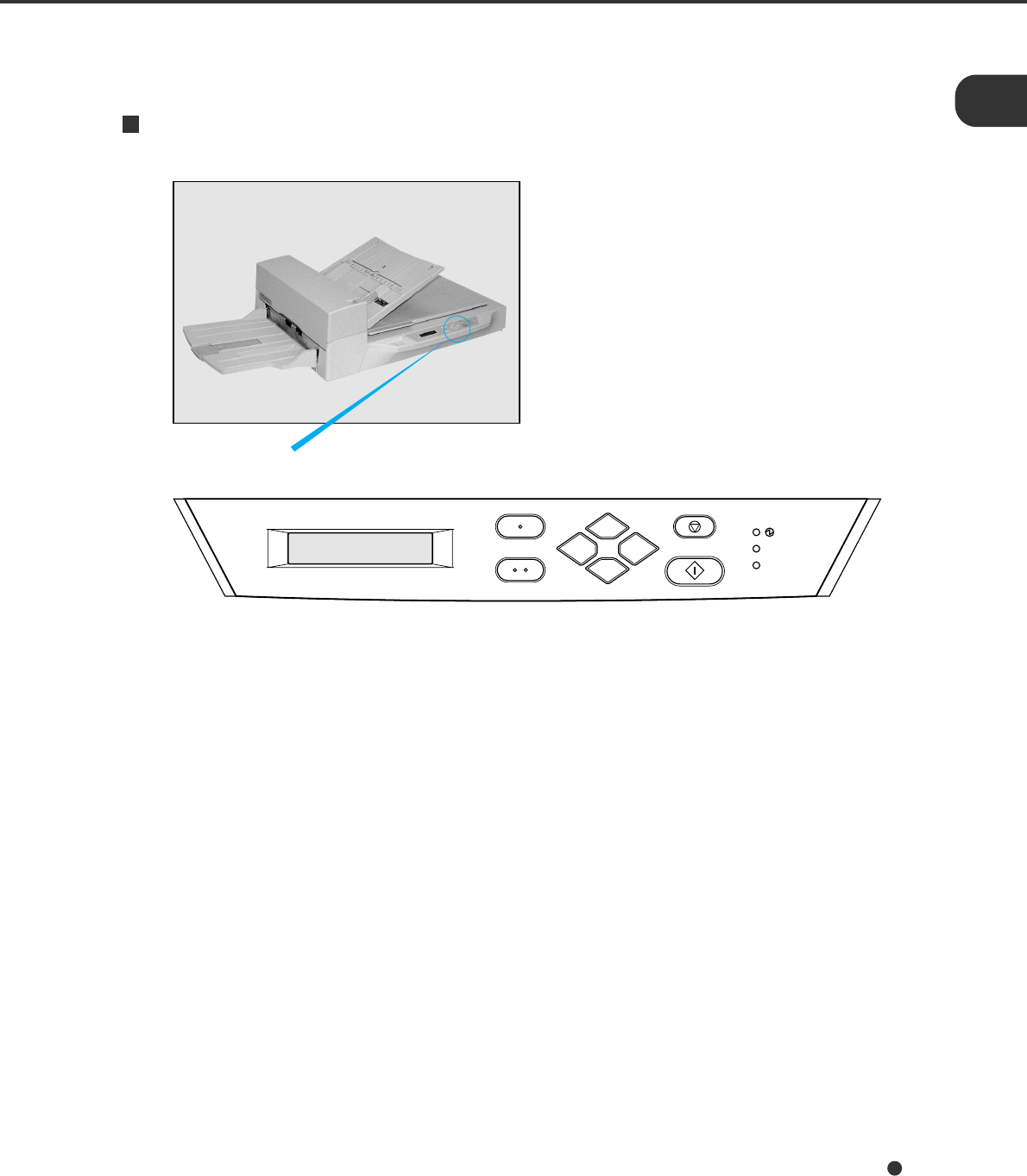
Operator panel
Exit
Enter
Stop
Previous
Next
Send To/
Start Read
Check
Operator Panel
The operator panel is located on the upper right hand side of the scanner. The panel consists of an LCD
display (16 characters x 2 lines), LEDs and buttons.
Arrangement
1-6
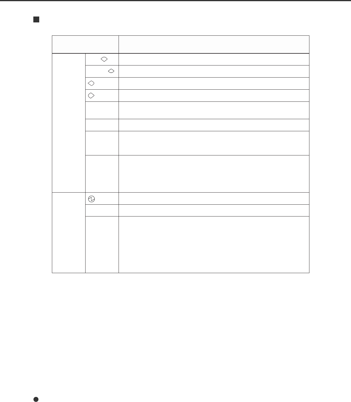
Button/LED Function
dnanottubehtfoemaNdnanottubehtfoemaNdnanottubehtfoemaNdnanottubehtfoemaNdnanottubehtfoemaN
DEL noitcnuFnoitcnuFnoitcnuFnoitcnuFnoitcnuF
nottuBtxeN .neercsDCLtxenehtsyalpsiD
suoiverP .neercsDCLsuoiverpehtsyalpsiD
.tfelehtotrosrucehtsevoM
.thgirehtotrosrucehtsevoM
tixE nottubsihtgnisserp,lenaprotarepOehtnosgnittesgniretneerauoynehW .neercs”ydaeRrennacS“ehtotyletaidemmiuoysnruter
retnE .rosrucehtybdetcelesyltnerrucretemarapehtsretnE
/oTdneS
tratS rotessiedomtratslaunaMnehwsthgilpmal”daeReht“elihwylnolanoitarepO noitacilppaemoS.gnidaerehtstratsdna,desusinoitpoecafretnioediveht .nottubsihtesuthgimsegakcaperawtfos
potS sinoitpoecafretnioedivehtnehwnoitarepodaerehtgnirudylnolanoirarepO .gnidaerehtspotsdna,desu sutatsrorreehtsesaelernottubsihtgnisserp,sthgilDEL”kcehC“ehtnehW ehtffosnrutoslA.)neercs”ydaeRrennacS“ehtotsnruterdna”kcehC”ffosnrut(
.pmal”kcehC“
DEL .nOsirennacsehttahtsetacidnI
daeR .daerotydaerrognidaersirennacsehtsetacidnI
kcehC nottub”potS“ehtgnisserP.derruccomralanatahtsetacidnisiht,tilfI• .ffOpmal”kcehC“ehtsnrut deefelbuodromajatahtsnaemsiht,slavretnidnocesenotasknilbtifI• demmajehtgnivomer,repapdemmajsimelborpehtfI.detcetedneebsah gnisserp,deefelbuodsimelborpehtfI.pmal”kcehC“ehtffosnrutrepap .pmal”kcehC“ehtffosnrutnottub”potS“eht siFDAehtgninaelctahtsnaemsiht,slavretnisdnocesruoftasknilbtifI•
.yrassecen
1-7
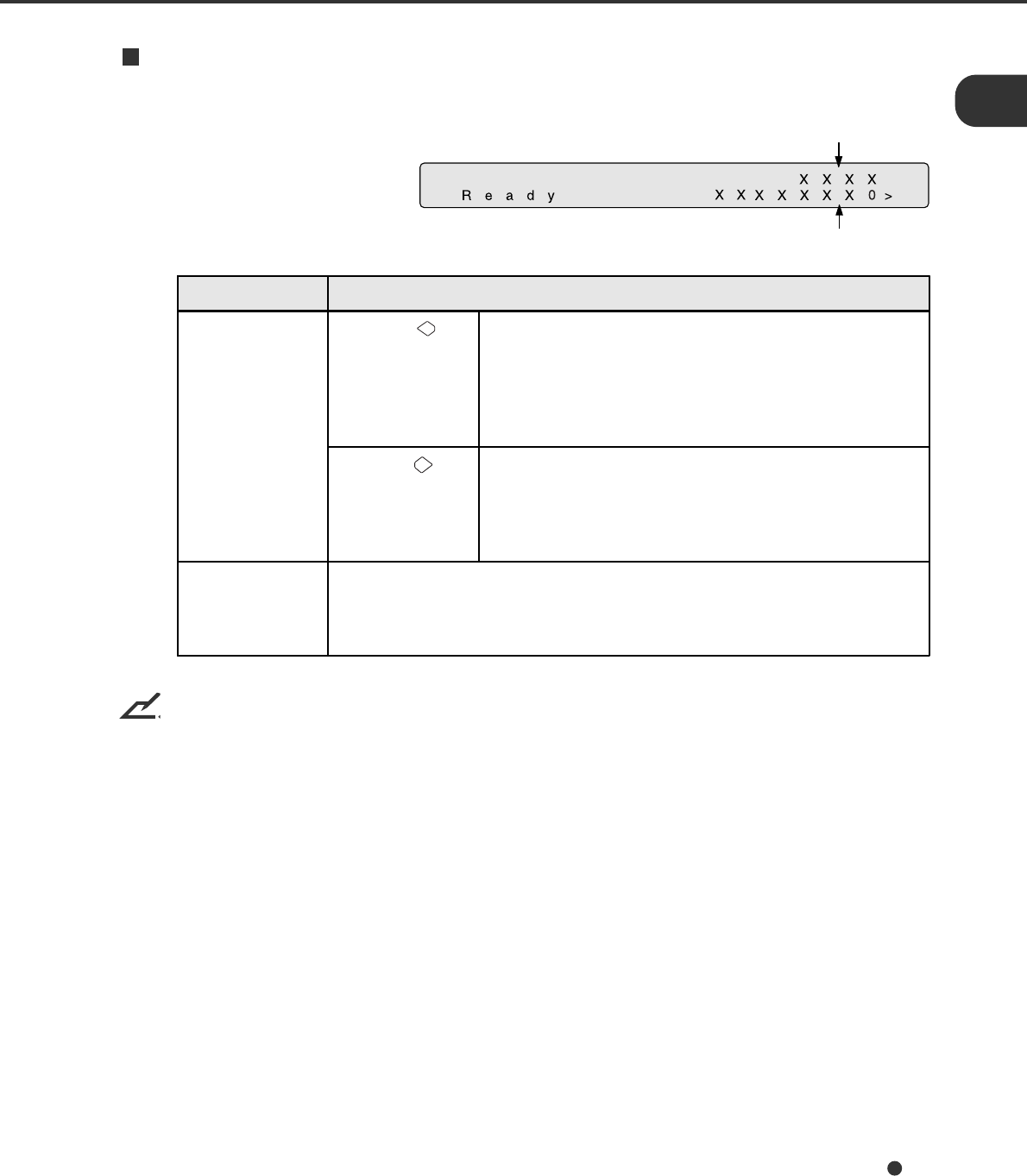
Counter Display
The scanner is provided with a counter display.
NOTICE
When the counter value is 0, no number is displayed.
Paper counter
Counter Function
Paper counter When the
button is pressed The paper counter counts the number of scanned sheets
from the start of reading until Paper Empty or an error is
detected. The counter is automatically reset at the start
of reading. The counter is used for checking the
number of the sheets scanned in one batch.
When the
button is pressed This counter increments each time a document is
scanned. It is not initialized until the power is turned off.
The counter can be used, for example, for checking the
number of sheets that have been scanned in one day.
Abrasion counter The abrasion counter counts the accumulated number of scanned sheets.
This counter increments every 10 sheets. It is useful to check the cleaning
cycle or the parts replacement cycle. How to reset it is described in Chapter
6.
Abrasion counter
1-8
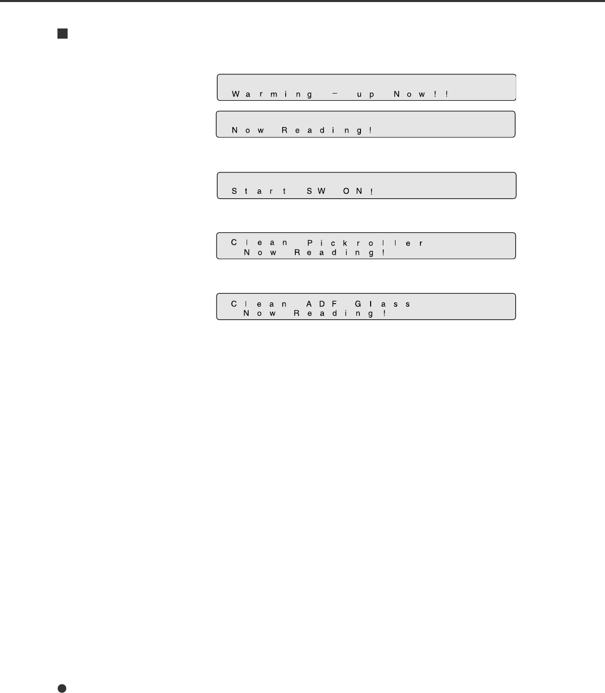
Operation status
The operation status is indicated by the following messages:
<Power-on>
<Reading>
<Waiting for Start> The scanner displays the following screen when waiting for the Start
button to be pressed:
(Only When the Video Interface
Option is installed.)
<Cleaning request> When the Pick roller cleaning is necessary, the scanner displays the
following on the upper line:
When the ADF glass cleaning is necessary, the scanner displays the
following on the LCD:
Clean the Pick roller or the ADF glass in accordance with the manual,
“Cleaning and Maintenance”.

1-9
Temporary error
<Hopper empty>
This message is displayed if there is no more paper on the ADF paper
chute during a read operation in ADF mode. Fill the ADF paper chute
with paper. To enable the read operation, press the stop button.
<Jam>
This message is displayed if a document is jammed in the ADF. See
the “Cleaning and Maintenance” manual for removing jammed
documents.
<ADF cover open>
This message is displayed if the ADF is not closed completely. Close
the ADF completely, and enable the read operation.
<Double feed error>
This message is displayed when the ADF detects the Double feed
error. Check the document and re-scan the document.
<No print cartridge installed>
This message is displayed when the print cartridge is not installed in
the imprinter. Install the print cartridge.
<Print position error or paper
alarm>
This message is displayed when the print position (t mark) of the
imprinter is positioned out of the paper path or the stacker is full of
paper. Set the imprinter in place or remove paper from the stacker.
1-10
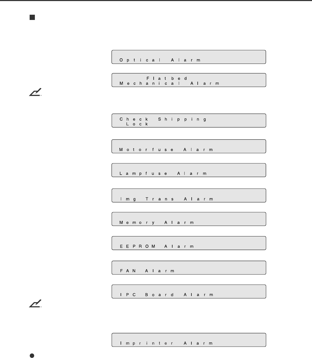
Alarm
One of the following messages is displayed if an error occurs in the scanner. If one of the following error
messages is displayed, turn the power Off and then On again. If the same message is displayed, contact
your service representative.
<Optical alarm>
<FB mechanism alarm>
NOTICE
When the total number of sheets scanned by the ADF is less than 100, the message above and the
message below are displayed alternately. Remove the bracket (Shipping Lock) that holds the carrier in
place.
<Motor fuse alarm>
<Lamp fuse alarm>
<Image transfer alarm>
(only when SCSI is used)
<Memory alarm>
<EEPROM alarm>
<FAN alarm>
<IPC board alarm>
NOTICE
When this message is displayed, turn Off system power and then turn it On again. Alternatively, replace
the current cable with one recommended by the manufacturer of the SCSI board. When the cause of the
alarm has been corrected, the scanner automatically resumes operation once power is turned On again.
<Imprinter alarm>

1-11
<Image transfer alarm>
<Memory alarm>
<EEPROM alarm>
<FAN alarm>
<IPC Board alarm>


2-1
Precautions
This section describes precautions to follow when installing the scanner.
To ensure the longevity and proper functioning of your scanner, do not install the scanner in the places
and environments described below.
• Place the scanner away from electrical noise sources, strong magnetic fields, and air flow. If the
scanner is used near an air conditioner, copying machine, or TV set, the scanner may operate
incorrectly.
• Keep the scanner out of the sun and away from heaters. These environments may shorten the scanner
life or cause hardware failures.
• Do not install the scanner in a place where vibrations may occur. This environment may cause
hardware failures or may cause the scanner to operate incorrectly.
• Do not install the scanner in humid, dusty, or damp places. These environments may shorten the
scanner life or cause hardware failures.
• Do not place the scanner where liquid spills may occur.
• Be aware of static electricity, which can damage the scanner’s sensitive electronic parts. Be sure the
flooring and the desk are made of materials that do not generate static electricity.
For information on the minimum required size of the installation space, see Chapter 5, “Specifications”.
2-2
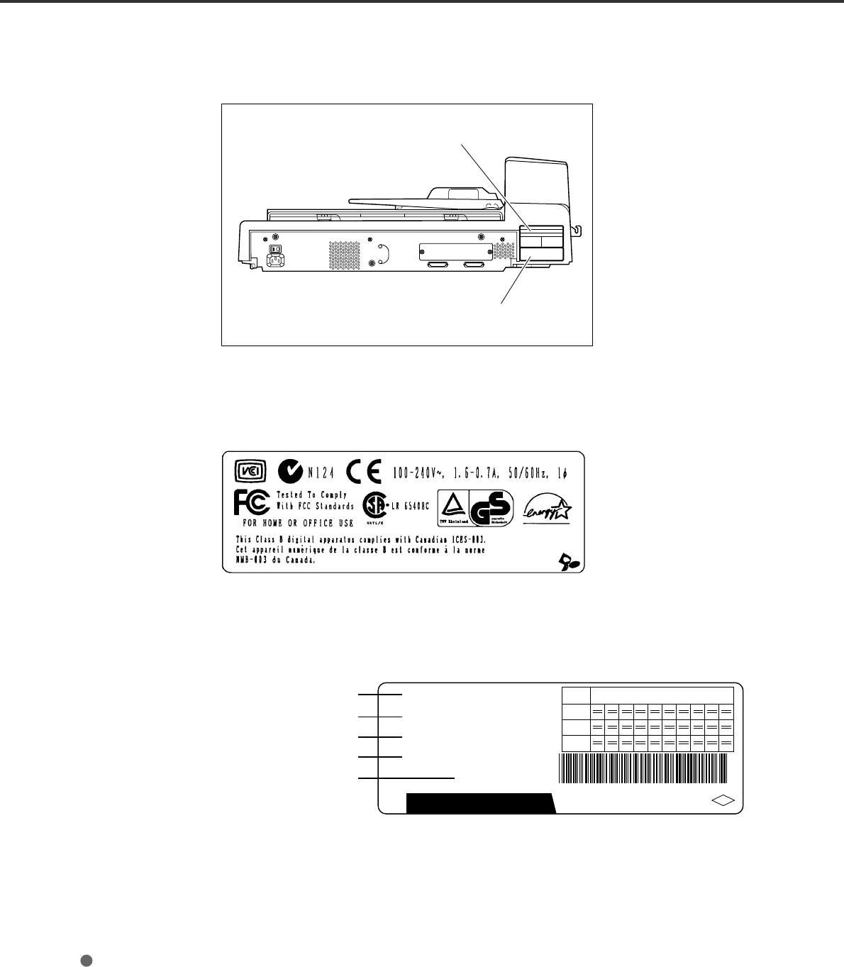
Inspection
This section describes how to check the labels.
Position of two labels
Label A (Example; your actual label may differ)
Indicates regulations and standards to which this scanner conforms.
Label A
Label B
A
B
MADE IN JAPAN
C
0123456789
ANS
Rev.
Label
fi-4640S
CA05951 -6420
000003
MODEL
PART NO.
SER. NO.
DATE
2001-7
21 Kg
**
FUJITSU LIMITED
0123456789
0123456789
fi 4640 0 00003
S
-
Label B (Example; your actual label may differ)
Indicates product information as follows:
Model name
Specification number
Serial number
Production date
Weight
2-3
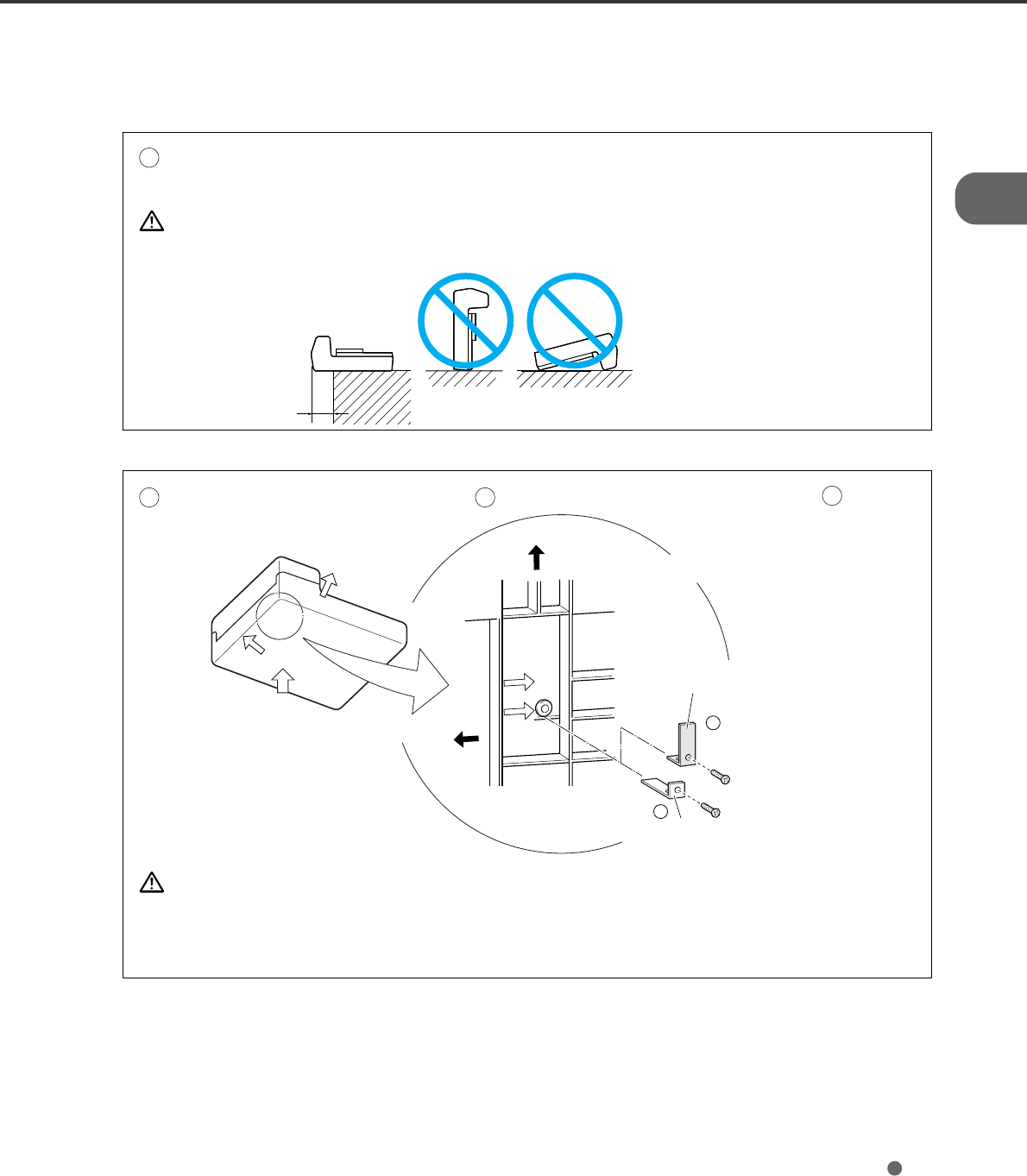
Repositioning the Shipping Lock
To keep the scanner from being damaged during shipping, the carrier unit is fixed with a Shipping Lock.
After placing the carrier unit where it will be installed, change the position of this Shipping Lock as
explained below.
1Place the image scanner on the edge of the desktop so that the left side of the scanner (where the
ADF is attached) extends from the desktop. Do not set the image scanner upside down or on its
side.
CAUTION
Do not let the scanner hang more than 20 cm (8 in.) over the edge of the desk.
2Remove the shipping lock from position A. Then, install the shipping lock at position B.
CAUTION
Before moving or storing the scanner, make sure that the shipping lock is set to the
shipment position to prevent possible damage. Before setting the shipping lock, make sure
that the carrier has been returned to the home position.
B
A
Good
Bad Bad
less than 20 cm
(8 in.)
Front side
Front side
Enlarged
Shipping Lock
(Position for operation)
Shipping Lock
(Position for shipment)
ADF side
Bottom view
Shipping Lock
(Position for storage,
position for shipment)
Enlarged section A
2-4
Cable Connections
This section describes how to connect the cables.
Connect the cables as follows:
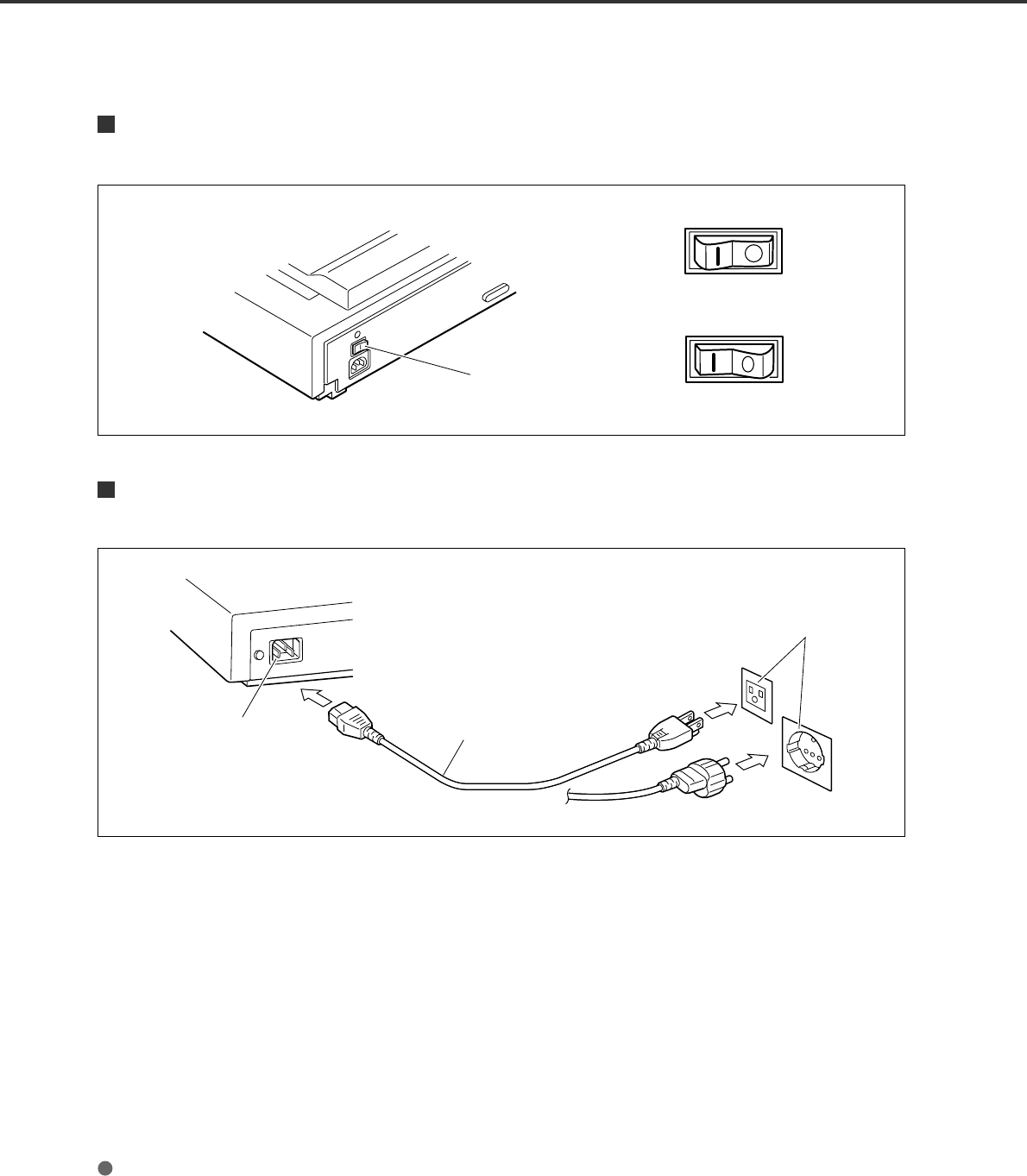
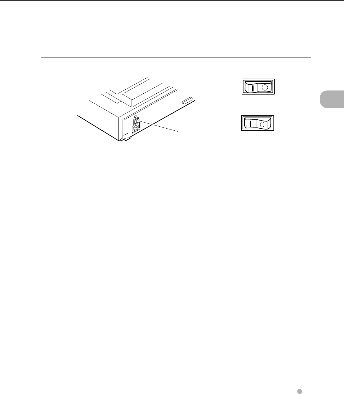
Turning the power switch Off
Press the “O” side of the power switch to turn the power Off.
Connecting the power cable
Connect the power cable to the power inlet of the device and a power outlet.
Power inlet Power cable
for North America
for Europe
Power outlet
Power OFF
Power ON
Power switch
2-5
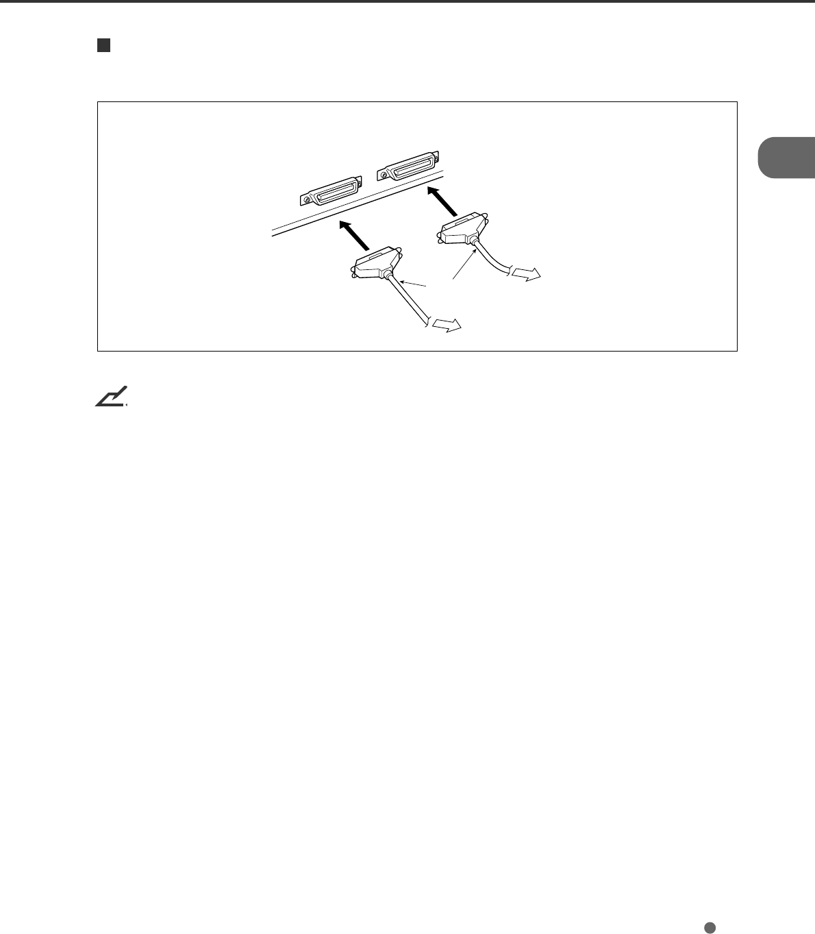
Connecting the interface cables
Connect the SCSI interface cables and secure them.
NOTICES
1. Factory default for the SCSI terminator is On. If the scanner is in the middle of the daisy chain or of two
devices, turn the scanner termination Off via the operator panel.
2. The factory default for the SCSI ID is 5. If the ID of the scanner is the same as the other device,
change the ID via the operator panel or change the ID of the other device.
Back of the image scanner
Interface
cables To the host system
2-6
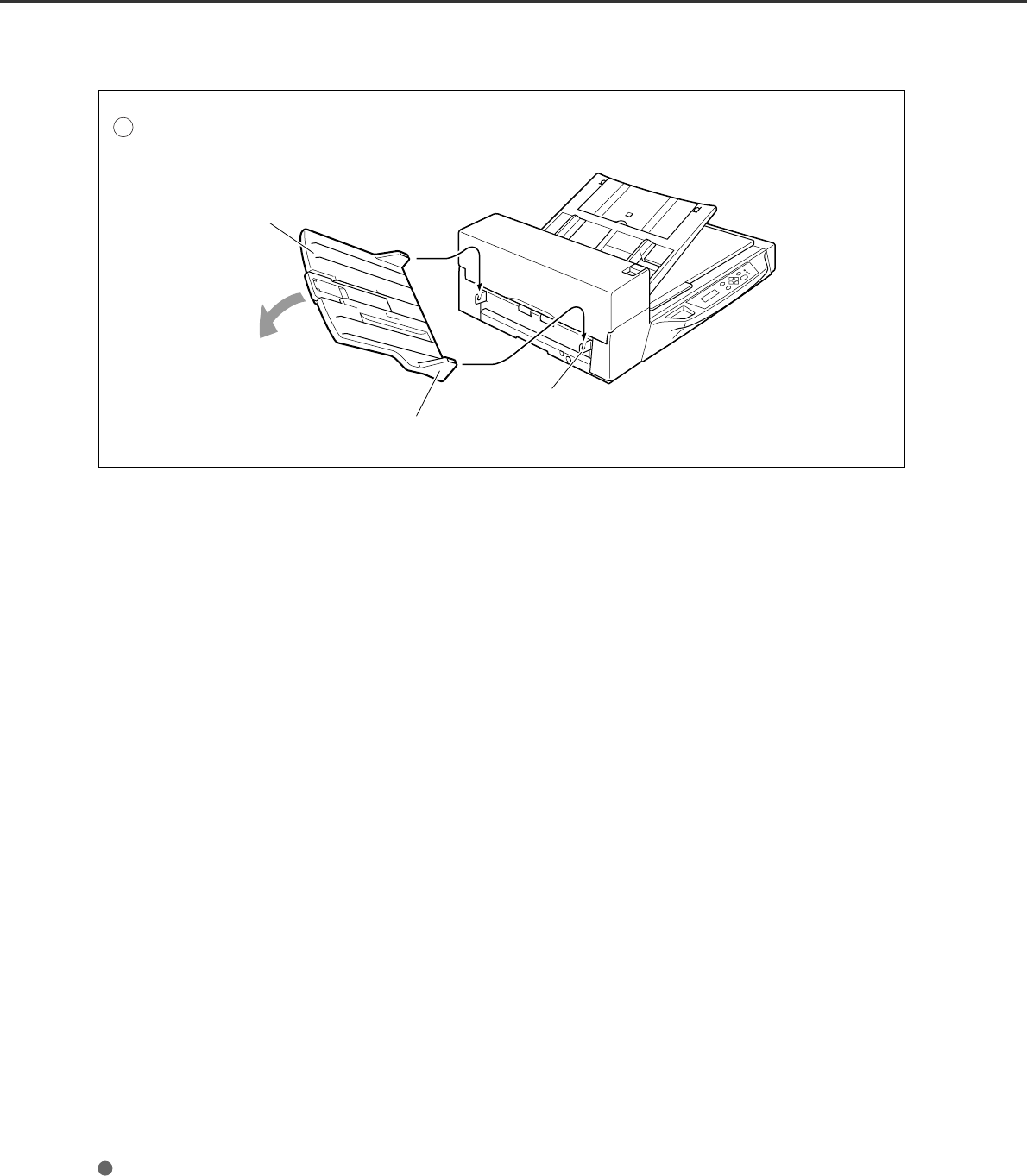
Mounting the Stacker
Mount the stacker using the following procedure.
1Mount the stacker.
Hook the pins on the stacker to the claws on the image scanner.
Stacker
Pin (inside)
Claw
2-7
Setting the SCSI ID and the SCSI Terminator
The default of the SCSI ID is 5. The SCSI ID is set by using the Setup mode of the operator panel. The
procedure to change the SCSI ID is as follows:
1Turn the power On by pressing
the “I” side of the power switch
(see Figure 1.1). The scanner
displays “Scanner Ready” on the
lower line of the LCD.
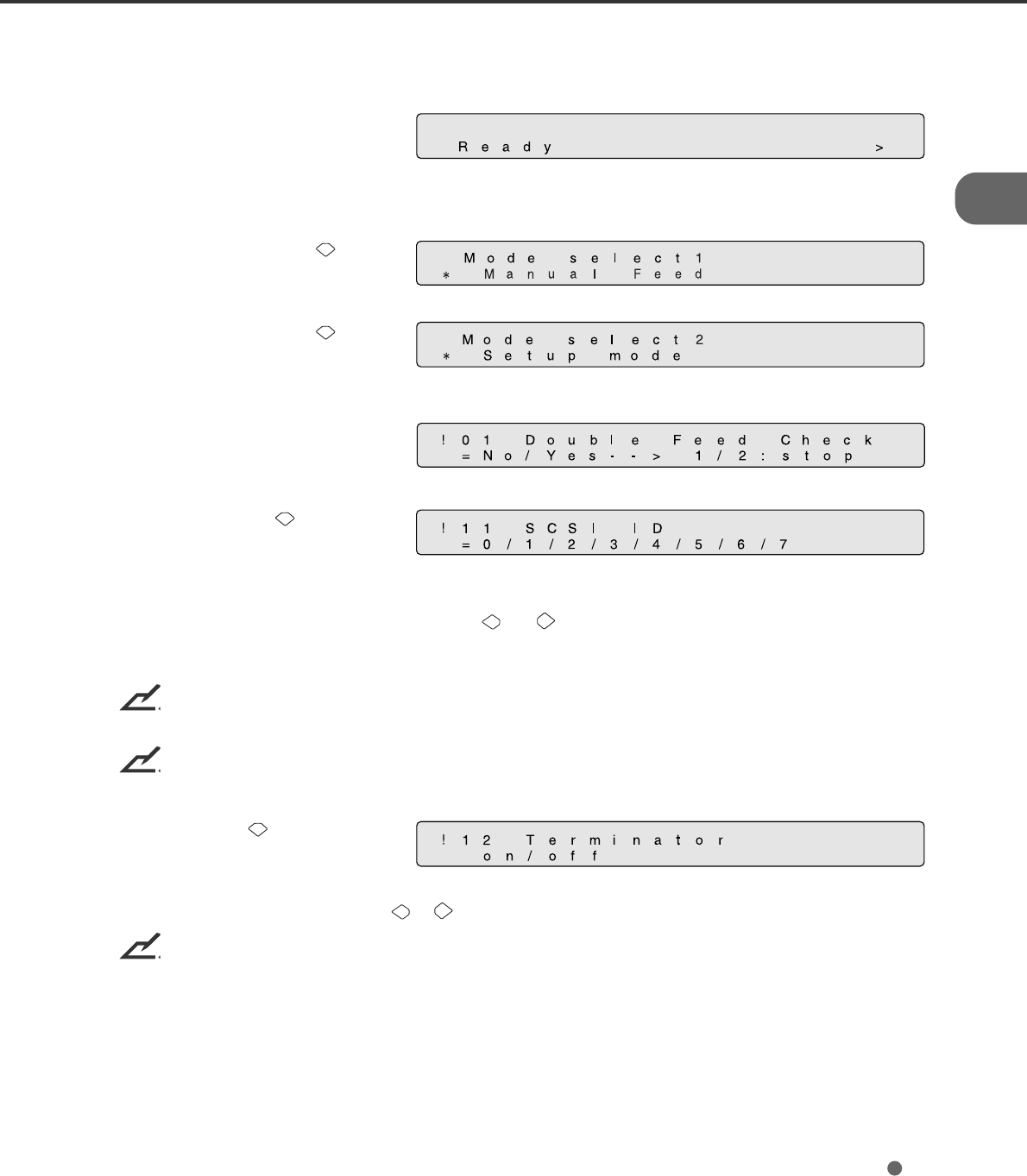
2Then press the “Next” button.
The scanner displays “Mode
select 1”.
3Then press the “Next” button.
The scanner displays “Mode
select 2” meaning that the setup
mode is ready.
4Then press the “Enter” button
several times. The scanner
displays the following:
5Press the “Next” button
several times, then the scanner
displays “SCSI ID” on the upper
line of the LCD.
6Select the wished SCSI ID by pressing the “ ”or “ ” button, and press “Enter” (the SCSI ID is set.)
7Press “Exit” to return to the “Scanner Ready” screen if you don’t need to change the SCSI terminator.
NOTICE
If no other device is using the same SCSI ID, the scanner ID does not have to be changed.
NOTICE
The new ID does not take effect until the system power is turned On again.
8Press “Next” , then the
scanner displays “Terminator” on
the upper line of the LCD.
Select “On” or “Off” by pressing or , then press “Enter”.
NOTICE
The scanner includes a SCSI terminator that can be turned On and Off from the operator panel of the
scanner. The factory default is “On.”
9Press “Exit” to return to the “Scanner Ready” state.

2-8

3
CHAPTER
OPERATING INSTRUCTION
This chapter describes how to turn the power on, and gives button specifica-
tions and reading mode settings for both ADF and Manual modes, how to
load documents onto the ADF and Flatbed, how to load documents larger
than the Document bed, and how to read a page from a thick book.
Refer to the “Cleaning and Maintenance”manual for routine scanner mainte-
nance.
Turning the Power On
Waking up the Scanner from the Low Power Mode
Manual Feed Mode Setting
Loading Documents on the ADF
Loading Documents on the Flatbed
Loading Documents Larger than the Document Bed
Reading a Page from a Thick Book
3-1
Turning the Power On
This section describes how to turn the power On.
Press the “I” side of the power switch. The power turns On and the green Power lamp at the operator
panel lights.
Power Off
Power On
Power switch
3-2
Waking up the Scanner from the Low Power Mode
This section describes how to wake up the
scanner from the Low Power Mode.
To wake up the Scanner, simply press a button,
set the papers on the ADF, or send a command
to scan from the host computer.
NOTICE
As an ENERGYSTAR® partner, Fujitsu Limited
declares that this scanner meets the
ENERGYSTAR® guidelines for energy efficiency.
3-3
Manual Feed Mode Setting
In this mode, the scanner waits for some predetermined time before issuing a “Paper Empty” message
after all documents are read. This predetermined time (time-out limit) is specified in the Setup mode.
Therefore, you can set the next documents on the ADF chute without interrupting the reading operation.
The procedures for setting the manual feed mode are as follows:
<Screen M1>
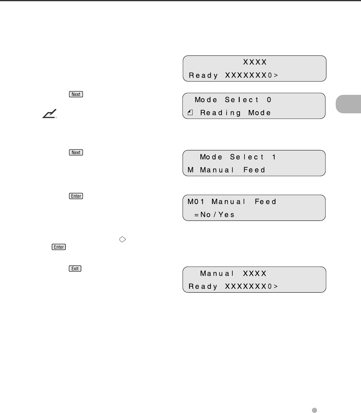
1Turn the power On and verify that “Scanner
Ready” is displayed on the LCD.
<Screen M2>
2Press then the scanner displays
Screen M2.
NOTICE
The “Mode Select 0” screen is skipped over to
“Mode Select 1” when your scanner is controlled
through the SCSI interface. <Screen M3>
3Press then the scanner displays
Screen M3.
<Screen M4>
4Press then the scanner displays
Screen M4.
5Select “Yes” by pressing . Then press
.
<Screen M1>
6Press to return to the “Scanner Ready”
screen. Note that “Manual Feed” is shown on
the LCD. This means that the scanner is in
Manual Feed mode.
3-4
Loading Documents on the ADF
NOTICE
Be sure to change the position of the shipping lock according to the “Installation and Connection”
procedure before operation.
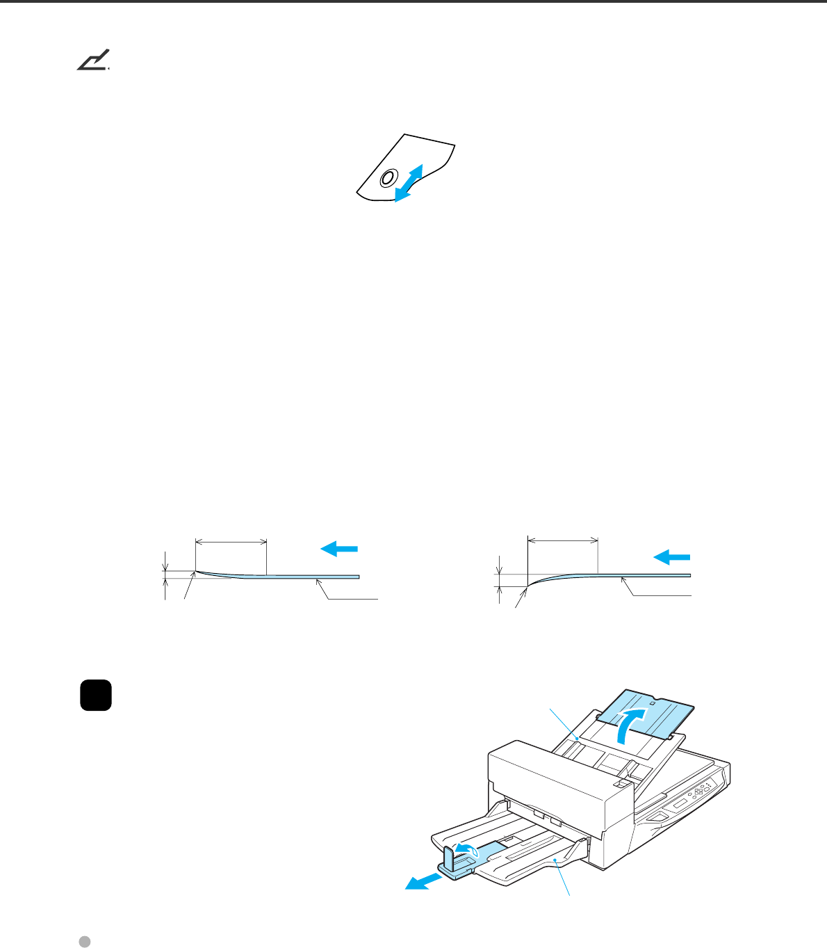
1
Lift up the ADF paper chute and lock the
bar in its operating position.
Stacker
ADF ADF paper chute
Guide
Guide lever
ADF lever
Operating position Bar
3-6
NOTICES
Note the following when preparing the paper.
• Remove paper clips and staples. Flatten the staple holes.
• Read the following documents using the Flatbed:
- Paper with clips or staples.
- Paper written on with wet ink.
- Paper of uneven thickness (for example, envelopes).
- Paper with large rumples or curls.
- Paper with folds or tears.
- Tracing paper.
- Coated paper.
- Carbon paper.
- Paper shorter than A8 (portrait) size or wider than A3 size or 11 x 17 inches.
- Materials other than paper (for example, clothes, sheet metal, or OHP film).
- Photographic paper.
- Paper with perforations on the side.
- Non-rectangular paper.
- Very thin paper.
• Set documents on the ADF so that the curl of the leading edge does not exceed the measures shown
below.
• To avoid skewing, do not feed docments of different widths during the same batch.
3
Adjust the stacker extension to the
paper size, and then flip out the plate.
Less than
5mm
More than 30mm
Top of the paper
Less than
3mm
More than 30mm Feed direction
Top of the paper Read surface
Feed direction
Read surface
ADF paper chute
Stacker

3-6
NOTICES
Note the following when preparing the paper.
• Remove paper clips and staples. Flatten the staple holes.
• Read the following documents using the Flatbed:
- Paper with clips or staples.
- Paper written on with wet ink.
- Paper of uneven thickness (for example, envelopes).
- Paper with large rumples or curls.
- Paper with folds or tears.
- Tracing paper.
- Coated paper.
- Carbon paper.
- Paper smaller than A8 (portrait) size or wider than A3 size.
- Materials other than paper (for example, clothes, sheet metal, or OHP film).
- Photographic paper.
- Paper with perforations on the side.
- Non-rectangular paper.
- Very thin paper.
• Set documents on the ADF so that the curl of the leading edge does not exceed the measures shown
below.
• To avoid skewing, do not feed docments of different widths during the same batch.
3
Adjust the stacker extension to the
paper size, and then flip out the plate.
Less than
5mm
More than 30mm
Top of the paper
Less than
3mm
More than 30mm Feed direction
Top of the paper Read surface
Feed direction
Read surface
ADF paper chute
Stacker
3-7
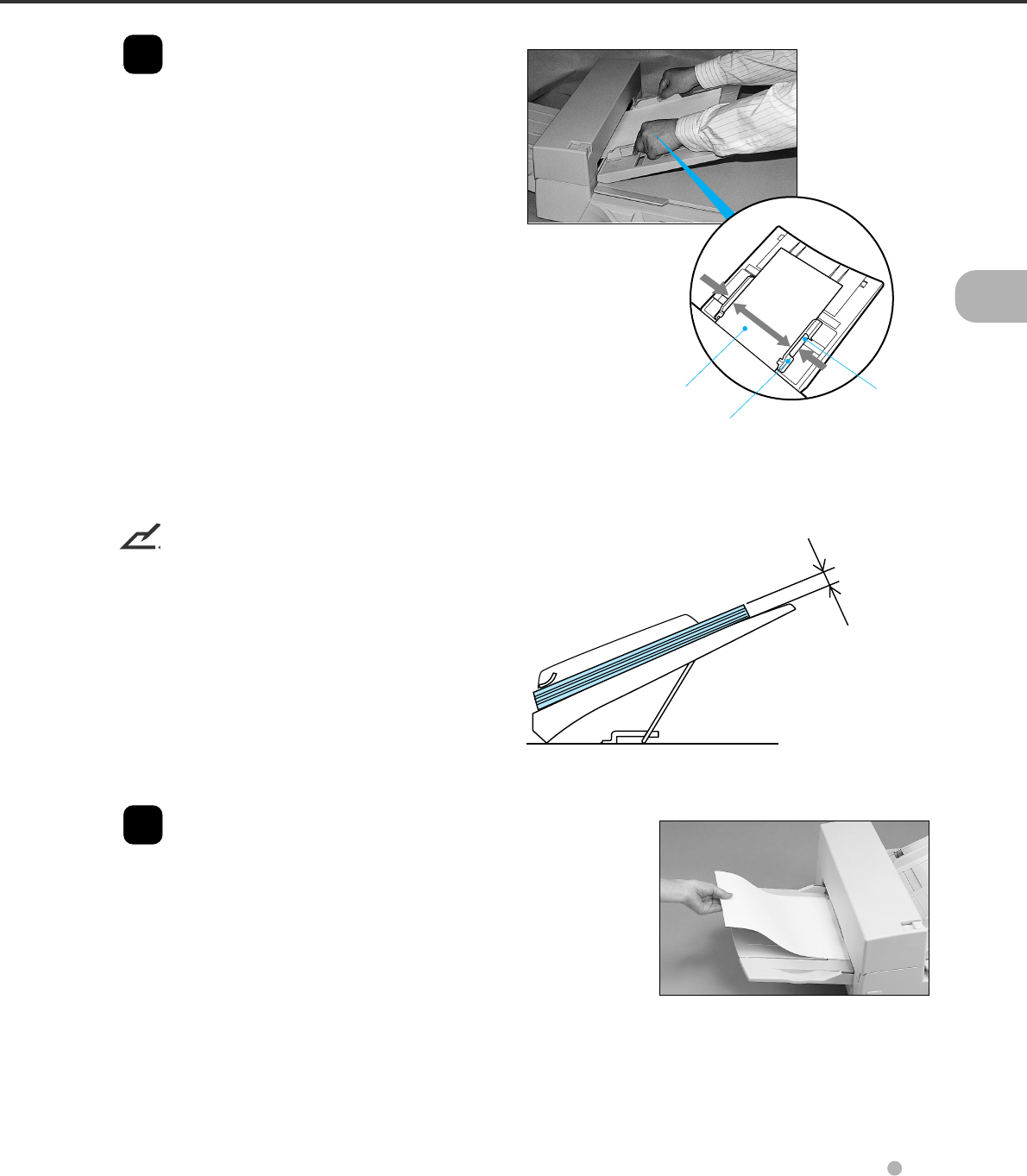
Guide lever
(Both sides)
Documents
Guide
max. 8 mm
(0.32")
4Set the guides so that there is a small
clearance between the document edges
and the guides. Load the document face
down on the ADF paper chute and adjust
the guides to the document width.
NOTICES
• Squeeze the guide lever to free the guides.
• Do not load document stacks thicker than 8
mm.
• Set the guides so that they touch the
document sides.
5After the read command is issued from
the host system and the documents are
read, scanned documents are expelled
into the stacker for removal.
3-8
Loading Documents on the Flatbed
CAUTION
Do not look directly at the light source during the read operation.
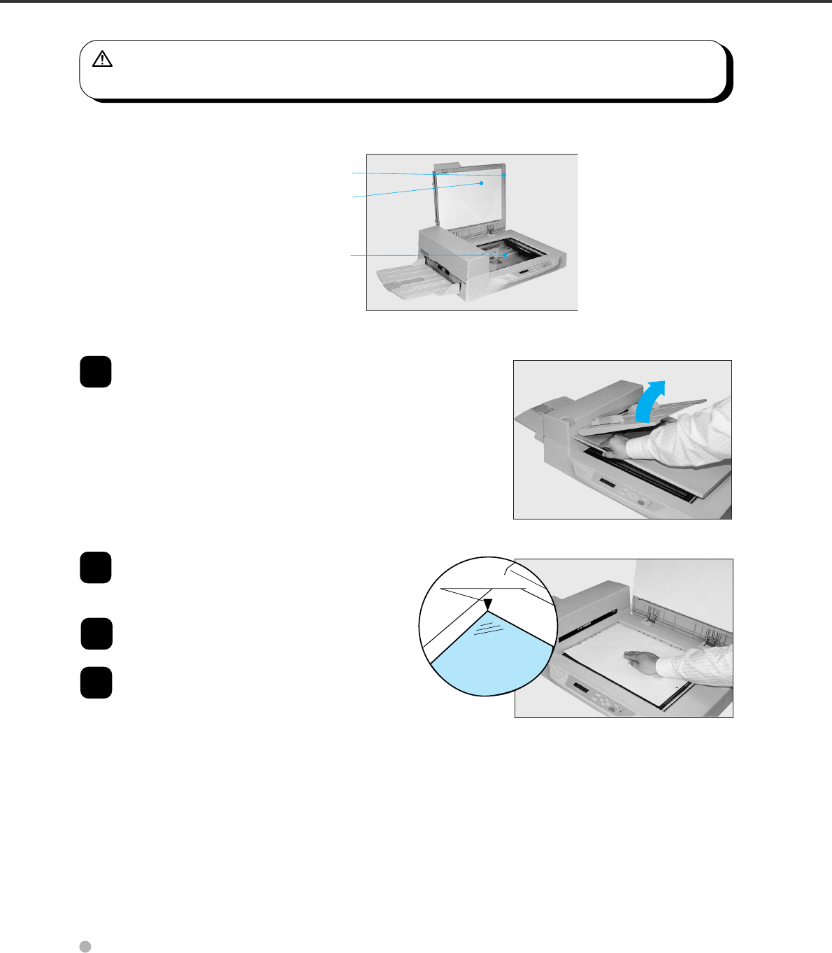
Scanner parts involved when loading documents
1
Open the document cover.
2
Place the document face down and align
the top left corner with the reference
mark.
3
Slowly close the Document cover.
4Issue the read command from the host
system.
Reference mark
Document cover
Document
holding pad
Document bed
3-9
Loading Documents Larger than the Document Bed
CAUTION
Do not look directly at the light source during read operation.
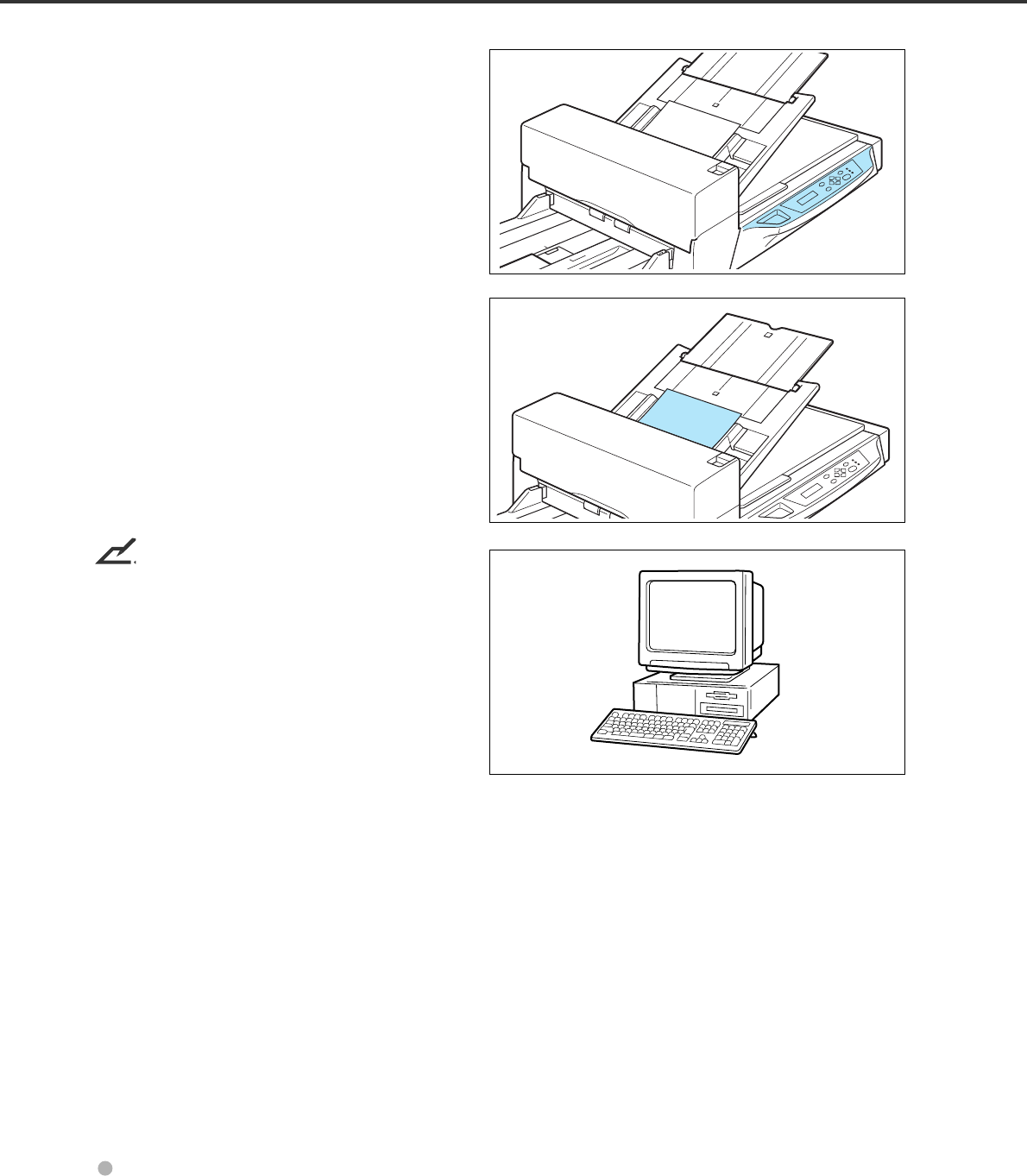
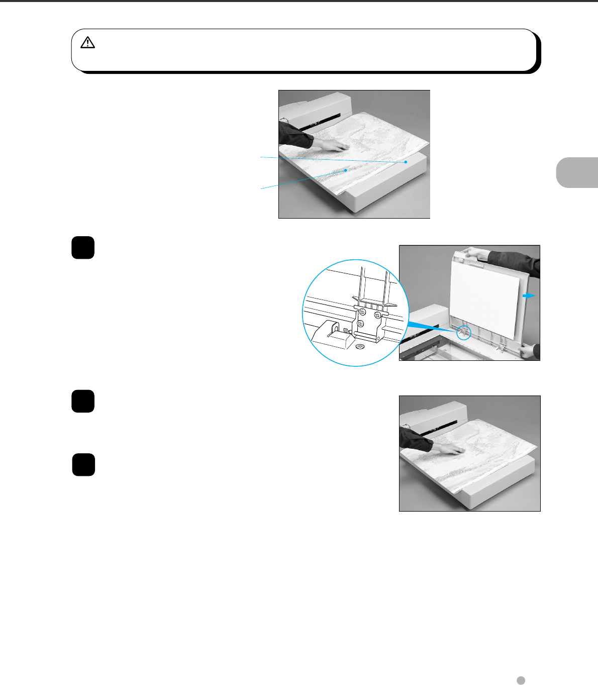
1
Open the Document cover to an angle of
approximately 90 degrees and slide the
cover in the direction of the arrow to
remove it.
2
Place the document face down on the
Document bed. Issue the read command
from the host system.
3
After the read operation, remove the
document, re-attach the Document cover
and close it gently.
Document bed
Document
3-10
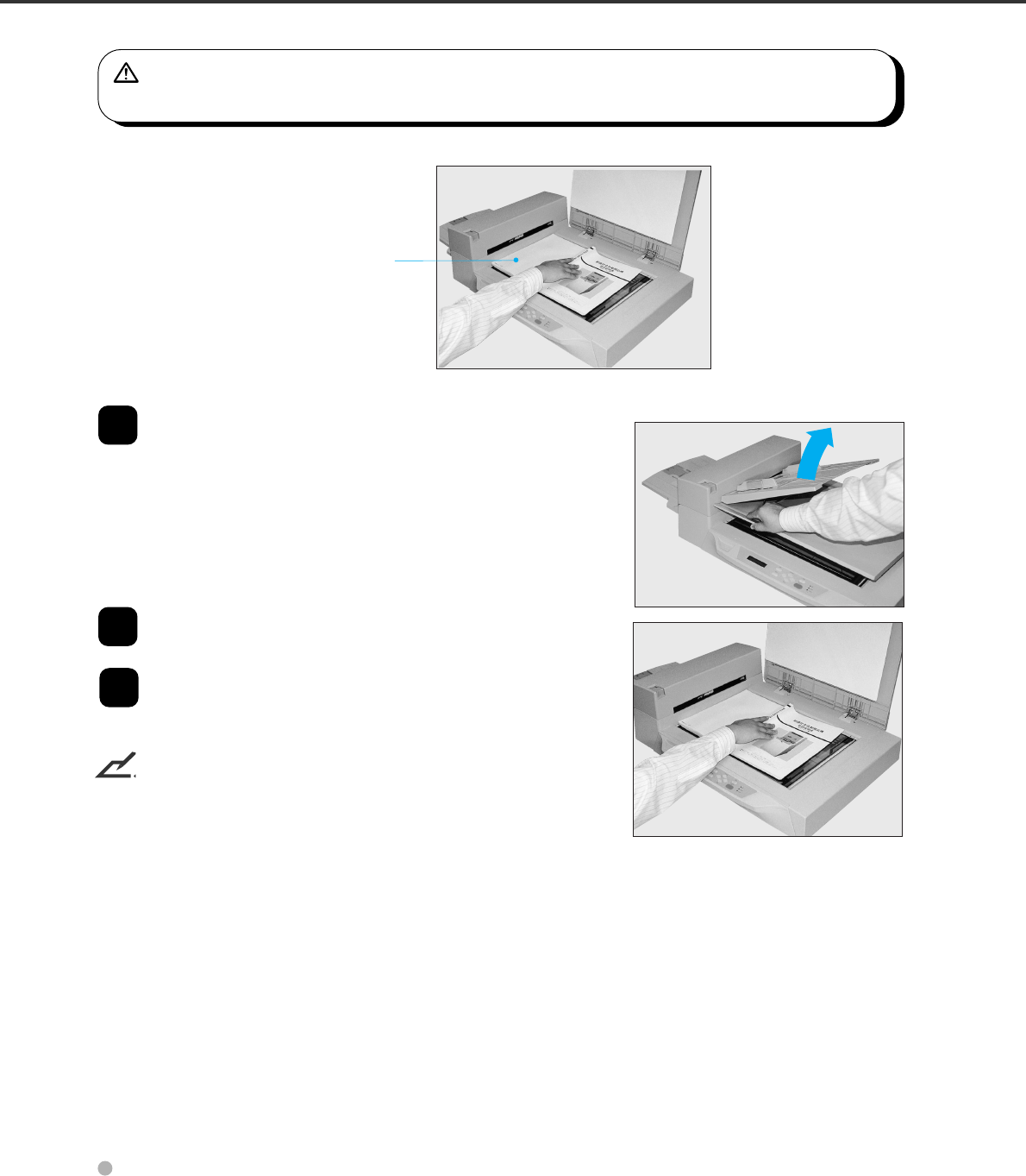
Reading a Page from a Thick Book
CAUTION
Do not look directly at the light source during the read operation.
1
Open the Document cover.
2
Place the book face down on the
Document bed.
3
Issue the read command from the host
system. Keep the cover open for the
reading operation.
NOTICE
Do not move the book during the read operation.
Thick book

4-1
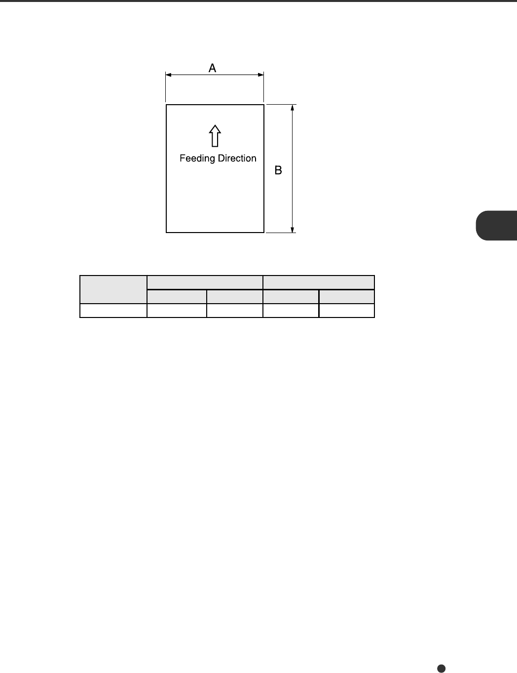
Document Size
The following figure shows document sizes that the scanner can read using the ADF.
Scanner Maximum Minimum
AB A B
fi-4640S 297 mm (11.7") 432 mm (17") 53 mm (2.1") 74 mm (2.9")

4-2
Document Quality
This section describes the types and weights of paper that the scanner can read and precautions in
preparing documents to ensure maximal scanner functioning.
Document type
The recommended paper type for documents is as follows:
• Woodfree paper
• Plain paper (for example, the paper type specified for XEROX 4024)
When using any other type of paper, test feed a few sheets with the ADF to ensure the paper feeds
properly before performing a large-scale reading operation.
Any paper can be used on the flatbed. However, the ground color specification must satisfy the
specification described in the Grounding Color Area section.
Paper weight
The paper weight should fall within the following ranges:
• 52 to 127 g/m2 (13.9 to 34 lb), 127g/m2 (34lb) for A8
Precautions
CAUTION
As there is always a slight chance that a document may be damaged when using the ADF, important
original documents should never be fed through the ADF. Instead, read them manually using the
flatbed.
A preliminary document feed test may be necessary to avoid unexpected errors. If document slip or jam
in the ADF (JAM error) or double feed occurs frequently, read the documents manually using the flatbed.
The following documents may be difficult to read properly using the ADF:
• Paper with clips or staples.
• Paper written on with wet ink.
• Paper without a constant thickness. (like envelopes)
• Paper with large rumples or curls. (See the NOTICE on the next page.)
• Paper with folds or tears.
• Tracing paper.
• Coated paper (for example, some paper used for color printing).
• Carbon paper.
• Paper smaller than A8 (Portrait) size, or larger than A3 or Double Letter.
• Materials other than paper (for example, clothes, metal foil, or OHP film).
• Photographic paper.
• Paper with notches on its side.
• Non-rectangular paper.
• Very thin paper.
4-3
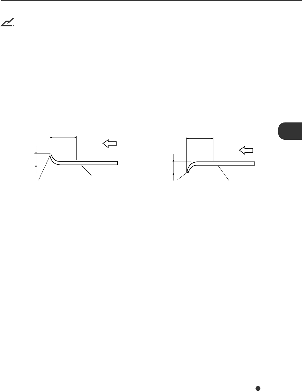
Less than
3 mm
Feed direc-
tion
Top of the paper Read surface
More than
30 mm
Feed direction
Less than
5 mm
More than
30 mm
Read surface
Top of the paper
NOTICES
1. When scanning a translucent document, set the density to light mode.
2. Carbonless papers have a chemical composition that damages the Pad and Pick roller. Therefore, note
the following:
Cleaning: If mispicks occur frequently, clean the Pad and Pick roller in accordance with
the “Cleaning and Maintenance” manual.
Replacement of parts: The life of the Pad and Pick roller may be shorter than if PPC paper
documents are fed.
3. The leading edge of all documents fed using the ADF should be straightened so the curl of the paper
meets the specifications shown below:
4-4
B4
67
79
52
39
61
41 50
33
25
31
50
100
100
80
60
40
20
052 64 81 104 127
A3 or
11x17
A4/Letter
or smaller
ADF chute
loading
(number of
pages)
ADF Capacity g/m2
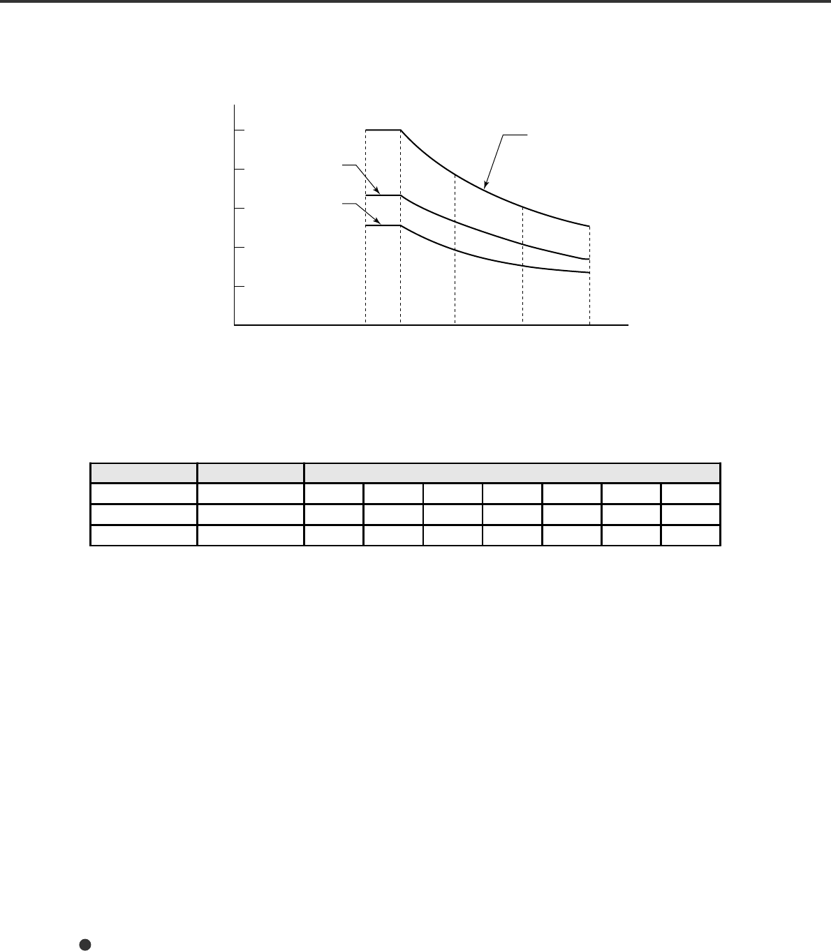
ADF Document Feeder Capacity
The number of pages that can be loaded into the ADF chute depends on the paper size and the ream
weight. This information is shown in the following graph:
Paper weight conversion table
Country Unit Conversion
Japan kg/ream 45 55 64.6 77.5 90 109.8 135
US lb 13.9 17 20 24 27.9 34 41.8
Europe g/m252 64 75 90 104 127 157
4-5
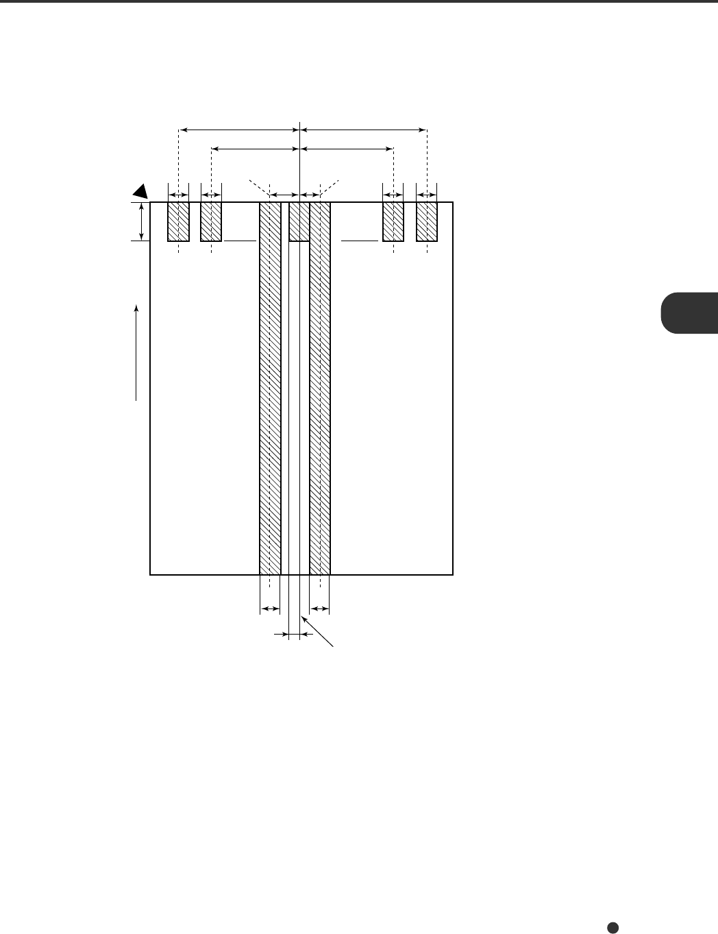
Areas not to be Perforated
With the ADF, perforations in the shaded areas may cause errors. If you must read data from such a
paper, use the flatbed:
113 134
9679
10
15
10 23 12 10 10
5
10 10
Areas that must not be perforated
Read reference
position
Center of
sensor arm Center of
sensor arm
(Unit: mm)
Top of paper
Front
side
Paper
feeding
direction
Bottom of paper
Center of paper
4-6
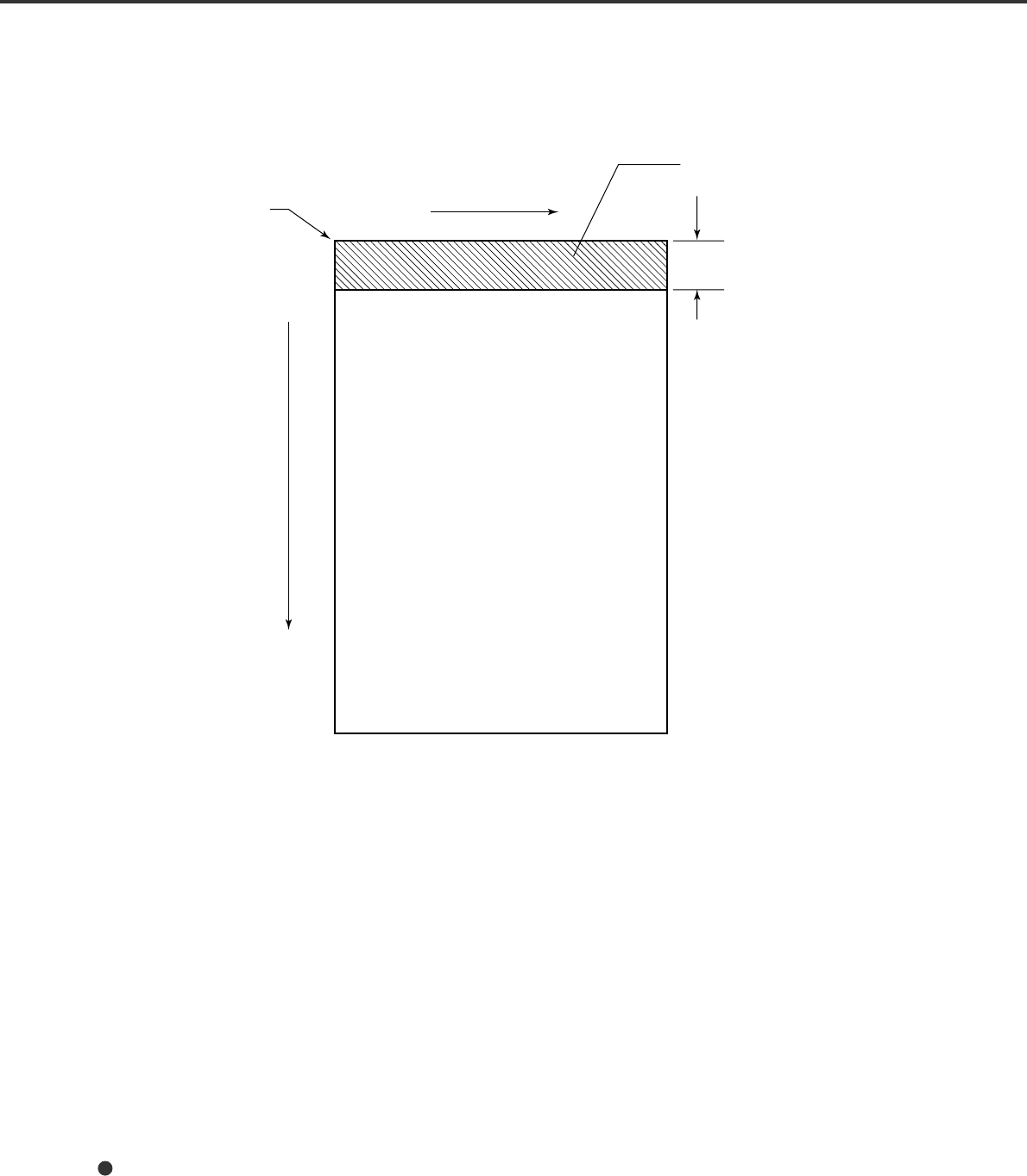
Grounding Color Areas
The shaded area in the Figure below should have paper grounding color (white) or drop-out color. If not,
turn the white level following Off when reading.
Grounding color area
3
Read reference
position
Main scanning direction
Grounding color (white)
or drop-out color area
Read surface
Subscanning
direction
Unit: mm
4-7
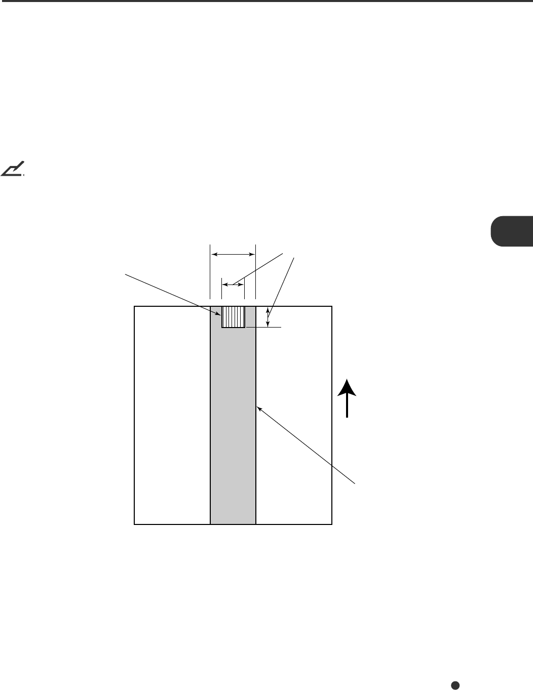
Double Feed Detection Condition
When the double-feed sensor is used, the thickness or the combination of the thickness and the length of
the document is subject to the following specifications:
1Thickness: 0.065 mm to 0.15 mm
2Paper length accuracy: 1% or less
3Any black print at the center of the leading edge of the paper is not allowed. (10 mm x 10 mm)
4No binding holes are allowed within 35 mm of the middle (halfway point) along the center of the paper.
5Printing duty: 12 % or less
6The deviation of the amount of transparent light on the base color area should be less than 10 %.
NOTICE
Certain paper types or a certain condition of paper result in lower detection rates in terms of double feed
detection.
35 mm 10 mm
No printing allowed
Paper feeding
direction
No binding holes allowed
4-8
Job Separation Sheet
1Shape
The following shows the typical format of the job separation sheet.
2Paper conditions
The paper conditions are the same as the specification described before. But the paper width must be
A4 or larger (210 mm or larger in width).
15
15
Reading direction
Top of paper
Bottom of paper
Center of paper
Job separation sheet


5-1
Basic Product Specification
Notes *1: The details are described in chapter 4.
*2: The actual scanning speed might differ due to host computers’ environment.
*3: These speeds do not contain processing time at the host computer.
*4: The maximum number will differ due to the paper thickness. Refer to chapter 4.
*5: The scanning speed might be slow. The usage with NO COMPRESSION is recommended.
*6: Both SCSI-2 and the Third Party Slot can not be used at the same time.
*7: The Power consumption of the boards should be as follows:
- In the Low Power Mode: Less than 0.35 A
- With fi-IPC4D option: Less than 1.5 A
- Without fi-IPC4D option: Less than 3.0 A
No.Item Specification Remarks
1Operating method ADF (simplex), flatbed
2Image sensor CCD x1
3Light source Inert gas (Xenon) lamp Green
4 Document
Size Minimum A8 (Portrait) 110 kg paper
Maximum A3 or 11x17
5Document Thickness 52 g/m2 (14 lb) to 127 g/m2 (34 lb) Note *1
6Optical Resolution 400 dpi
7Output
Resolution Binary 100/150/200/240/300/400/600/800 dpi
Grayscale 100/150/200/240/300/400/600 dpi
8Grayscale level (internal) 1024 levels (10 bits)
9 Scanning speed (mechanical)
Note *2 45ppm, 200dpi, A4, Portrait
32ppm, 300dpi, A4, Portrait
56ppm, 200dpi, A4, Landscape
Note *3
10 Halftone patterns Dither/Error diffusion
11 Capacity of ADF 100 sheets (A4, 64 g/m2 (17 lb)) Note *4
12 Compression MH/MR/MMR Note *5
13 Interface
Note *6 SCSI-2 High Density (Half)
50-pin, Female
Third Party Slot Note *7

5-2
Installation Specification
The following table lists the installation specifications of the scanner.
metImetImetImetImetI noitacificepSnoitacificepSnoitacificepSnoitacificepSnoitacificepS
)mm(snoisnemiD )rekcatSdnareppoHtuohtiW(
htpeDhtdiWthgieH
)"4.72(696)"5.02(125)"2.9(432
)gk(thgieW).bl3.64(12
rewoptupnI
egatloV%01±CAV042ot002roCAV721ot001
sesahPesahp-elgniS
ycneuqerFzH3±06/05
noitpmusnocrewoPsselroAV061
tneibmA
noitidnoc
sutatseciveDgnitarepOgnitarepotoN
erutarepmeT
C°53ot5
59ot14(°)F C°06ot02- )F°041ot4-(
ytidimuH%08ot02%59ot8
yticapactaeH)H/UTB313(H/lack87
)gk(thgieWgnippihS)bI5.95(72
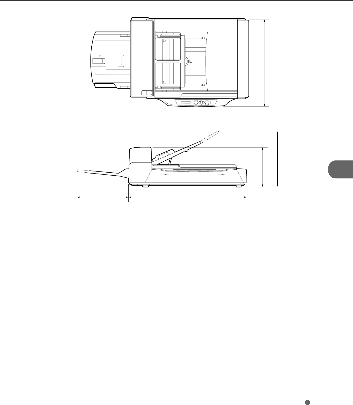
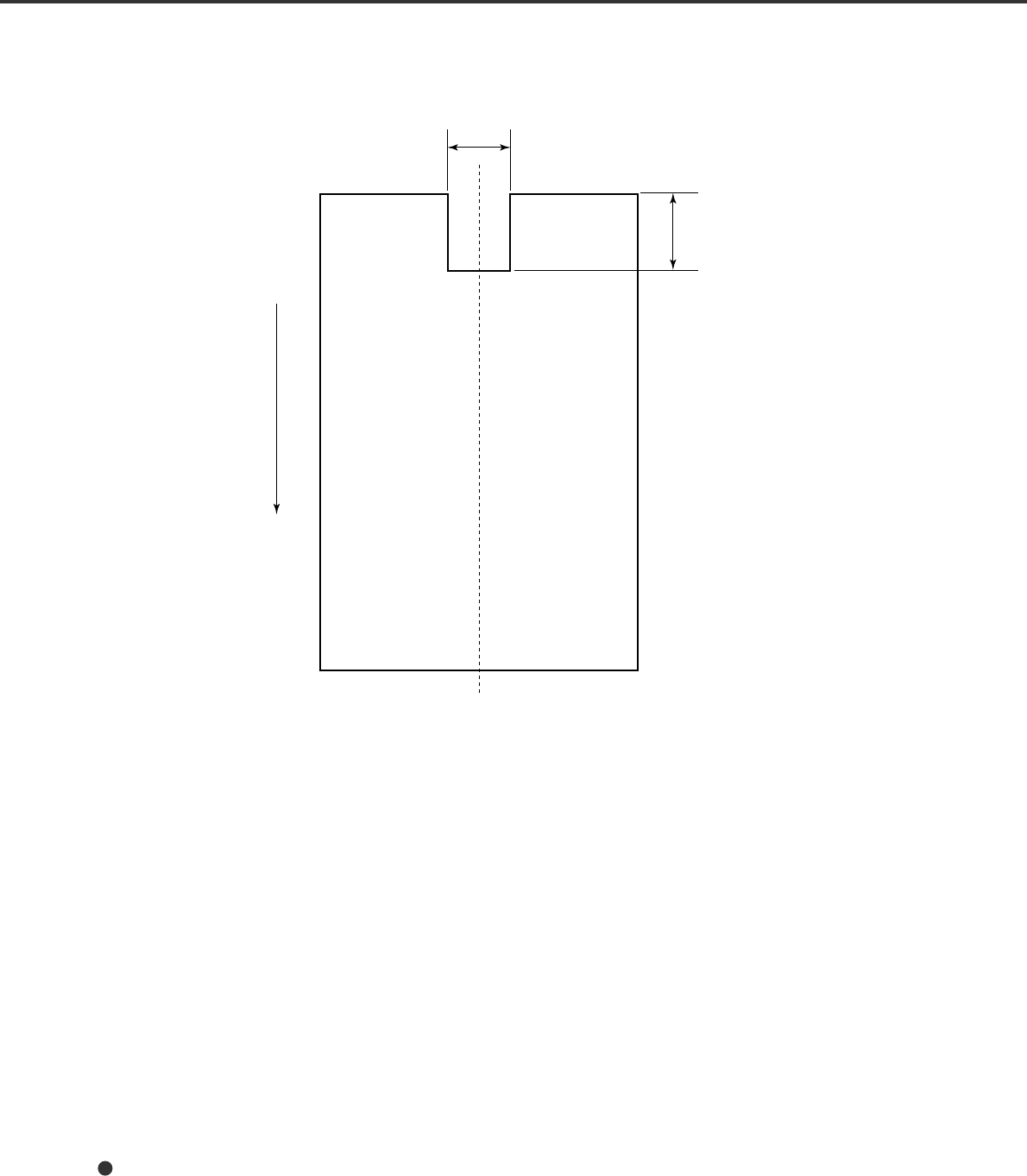
5-3
(unit: mm)
521
234
335
445 696
(17.5") (27.4")
(13.2")
(9.2") (20.5")
Dimensions

5-4

6-1
Consumables List
The following table lists consumables used for the scanner. Be sure to keep some consumables in stock.
The customer is responsible for changing these items periodically, in accordance with the guideline of the
service life given below and in the “Cleaning and Maintenance” manual. If they are not changed as
recommended, the scanner may not function properly. The abrasion counter can be used to check the
total number of documents scanned since the last replacement(s).
NOTICE
Refer to the Cleaning and Maintenance guide for replacing the consumables.
NOTICE
Certain paper types or conditions might reduce the life of consumables.
Name Specification Service life (guideline)
Pad ASY PA03951-0151 100,000 sheets or one year.
Pick rollers PA03951-0153 200,000 sheets or one year.
(Two rollers are included.)

6-2
Options List
The following table lists options available for the scanner.
Contact your representative sales agent for more information.
Name P/N Remarks
Video interface board CA02956-2391
IPC-4D CA02919-0521 IPC: Image processing circuit
One per unit
fi-475PR CA02956-2395 Imprinter unit with a print cartridge
6-3
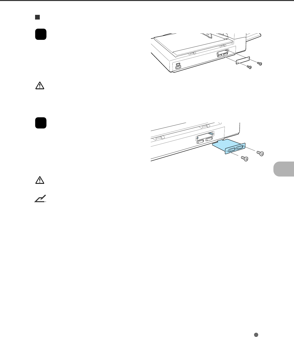
Video Interface Board Option
How to Install the Video Interface Board
1
Loosen the two screws to remove the
plate.
WARNING
Turn Off the power before removing the Third Party Slot plate.
2
Insert the board along the rails of the
third party slot. Make sure that the
connector is connected securely.
Secure the board with two screws.
CAUTION
Protective measures are required to prevent damage from static electricity.
NOTICE
When the scanner power is turned On again, the scanner automatically recognizes the video interface
board.
6-4
Reading Mode Setting When the Video Interface Board is Installed
This section describes the button specifications and setup details for reading modes when the scanner
has the video interface board in the third party slot.
When the reading mode is set by the command from the host computer, the following button operation is
not required.
NOTICE
When the video interface board is installed in the scanner, the scanner automatically recognizes the board
and changes the display.
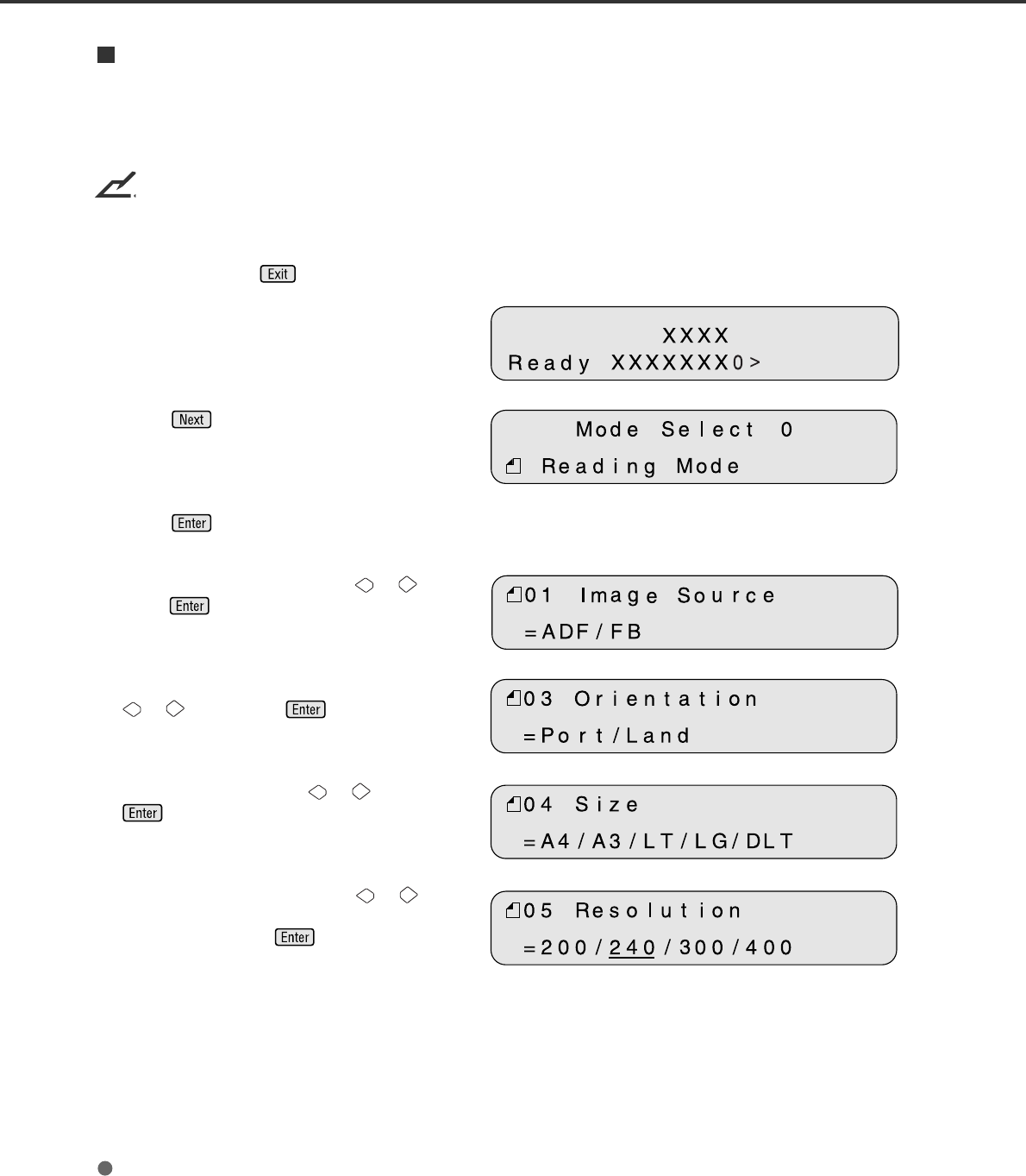
Whenever you press , the scanner returns to screen M1.
<Screen M1>
1 Turn the power On and verify that “Scanner
Ready” is displayed on the LCD.
<Screen M2>
2Press then the scanner displays
Screen M2.
3Press then the scanner displays
Screen 1. <Screen 1>
4Select ADF or FB by pressing or then
press . The scanner displays Screen 2.
<Screen 2>
5Select “Portrait” or “Landscape” by pressing
or . Then press . The scanner
displays Screen 3.
<Screen 3>
6Select Size by pressing or . Then press
. The scanner displays Screen 4.
<Screen 4>
7Select Resolution by pressing or . As
the cursor moves to the left 100/150 may
appear. Then press . The scanner
displays Screen 5.
6-5
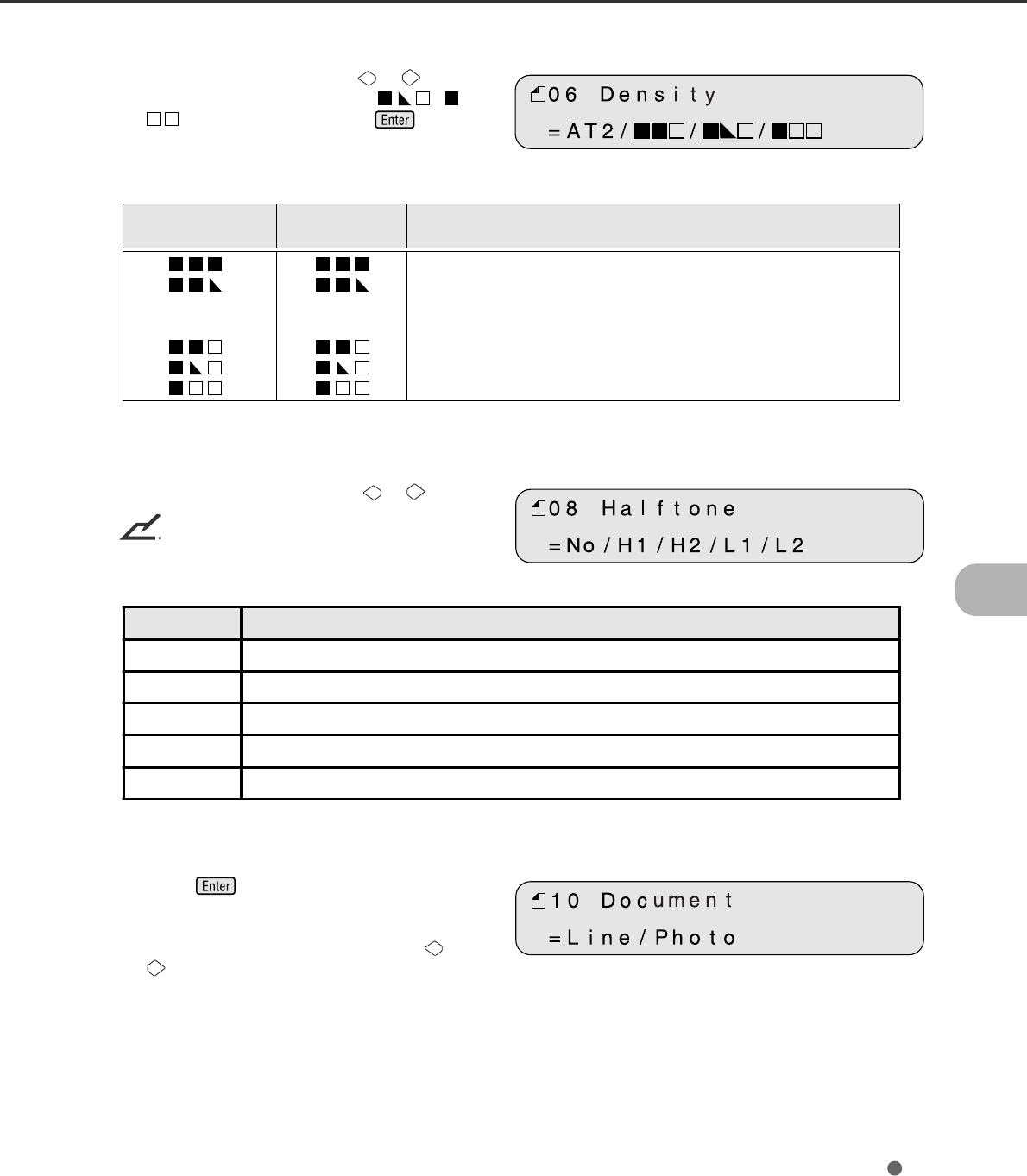
<Screen 5>
8Select Density by pressing or . As
the cursor moves to the right, /
may appear. Then press . The
scanner displays Screen 6.
Density display
Without IPC-4D With IPC-4D Description
option option
Very dark
Dark
AT1 (*) Dynamic Threshold (DTC mode)
AT2 AT2 (*) Simplified Dynamic Threshold (IPC mode)
Normal
Light
Very light
* This parameter appears only when the IPC-4D is installed.
<Screen 6>
9Select Halftone by pressing or .
NOTICE
This screen is disolayed when FB is selected in
Screen 1.
* This parameter appears only when the IPC-4D is installed.
<Screen 7>
Press to confirm. The scanner
displays Screen 7.
10 Select Document Type by pressing or
.
Parameter Description
No Halftone is Off . Therefore binary reading is specified.
H1 Halftone with dither is specified.
H2 Halftone with error diffusion is specified.
L1 (*) Automatic separation with dither is specified.
L2 (*) Automatic separation with error diffusion is specified.
6-6
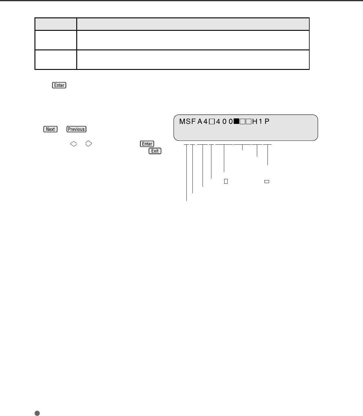
Front side (F)
Density
Halftone
Line Art (L) or Photo (P)
Resolution
Portrait or Landscape
Paper size
Simplex (S)
Press to confirm. The scanner displays
Screen 8.
<Screen 8 (Example)>
11 Confirm what you have specified.
If some parameter needs to change, press
or to select the corresponding
screen and re-select the parameter by
pressing or and finally press .
If all parameters are acceptable, press
to return to the “Scanner Ready” screen.
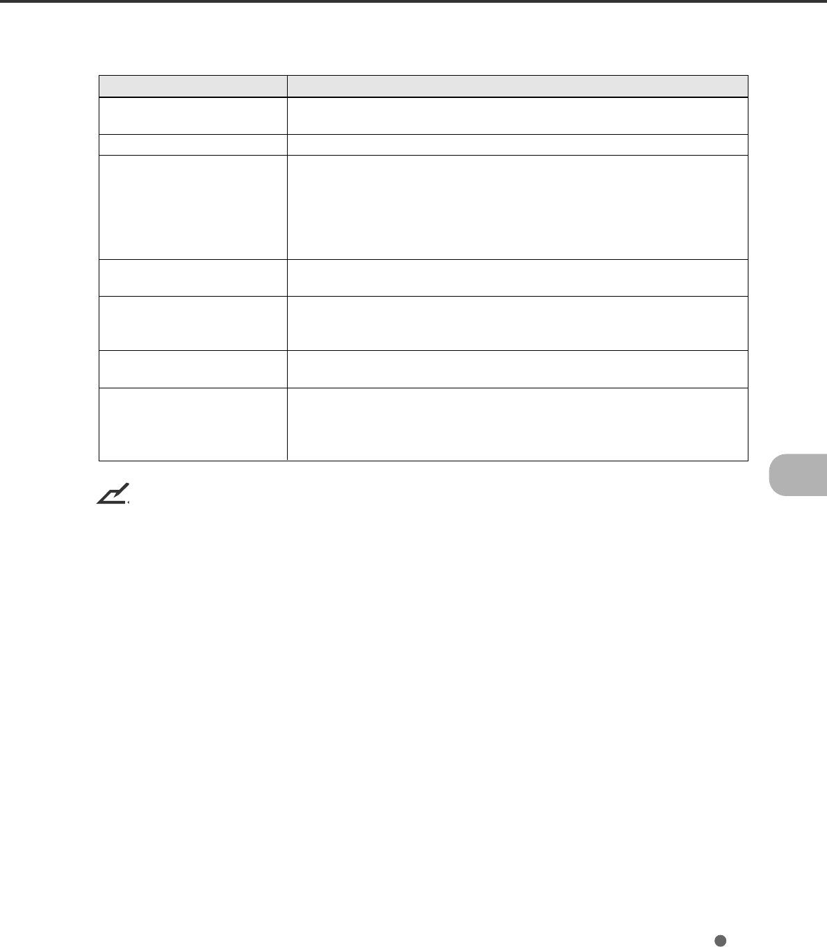
Parameter Description
L. (Line) White level following is ON. Top 3mm part of the document must be left blank
(grounding color is drop-out color). Use this specification for reading line arts or texts.
P. (Photo) White level following is Off
Use this specification for reading photographs.
6-7
IPC-4D Option
The IPC-4D option performs the following image processing.
Item Description
Pre-Filter Ball-Point Pen Filter :
Smooth ball point pen strokes.
Background Removal Remove background tone and light dither.
Dynamic Threshold One Pass / Two Pass Dynamic Threshold :
Adjust threshold level for binarzing to separate from background.
Captures the light text.
IPC-2 like Dynamic Threshold :
Adjusts the threshold level for binarzing to separate text from
backgrounds, thus capturing light text while preserving its sharpness.
Noise Removal 2x2 to 5x5 dot removal by matching :
Removes isolated dots in the size of 2x2 to 5x5 pixels.
Auto Separation Auto Separation :
Automatically, detects the text area for binarizing and the photo area for
dithering.
Outline Extract Outline
Extract outline of the image
Filter Emphasis (Low/High) :
Emphasis contour.
Smooth:
Smoothing image by averaging.
NOTICE
For the installation and functions of the IPC-4D, refer to the supplied manual.
6-8
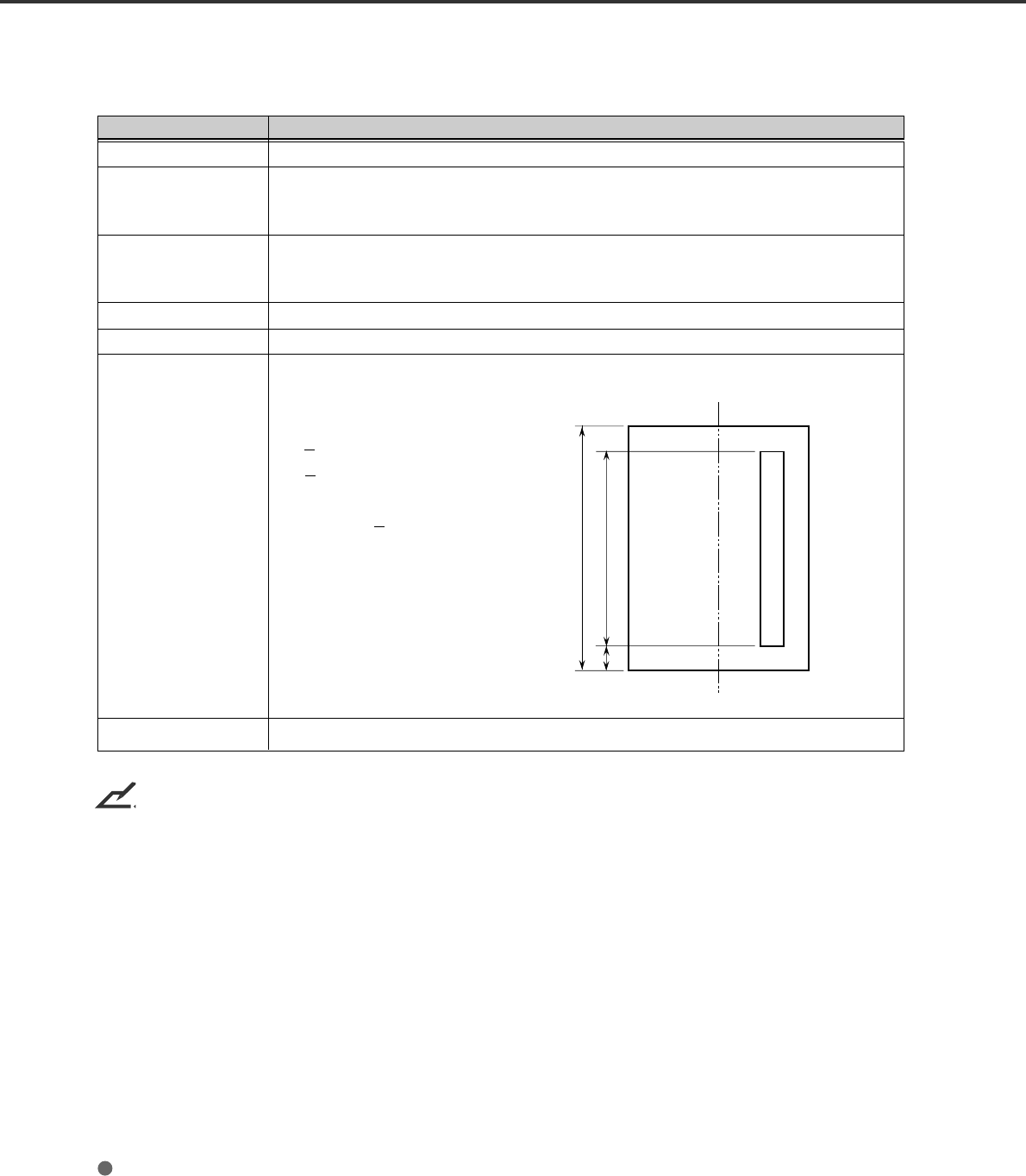
fi-475PR Option (Imprinter)
The following table shows specifications of the fi-475PR Imprinter.
Item
Printing Method
Printed Characters
Maximum Number of
Characters Printed
Character Size
Character Pitch
Printing Area
Consumable Print Cartridge
fi-475PR Imprinter Specifications
[Backside]
DT
ABC. . . . . . . . . . . . . . . . .
C
Center of Document
Specification
Thermal inkjet printing
Alphabet Letters: A to Z, a to z
Numeric Characters: 0, 1 to 9
Symbols: ! " # $ % & ' ( ) * + , - . / : ; < = > ? @ [ ¥ ] ^ _ ‘ { | }
40
Height 2.91 mm to width 2.82 mm
About 3.53 mm
The printable area of the backside of document is as follows:
T Length of document
D < 140.5 mm (for 40 columns)
C > 70.0 mm
T - (C + D) > 42 mm
-
NOTICE
For installation and functions of the fi-475PR Imprinter, refer to its supplied user's guide.

7-1
Activating the Setup Mode
This section describes how to activate the setup mode.
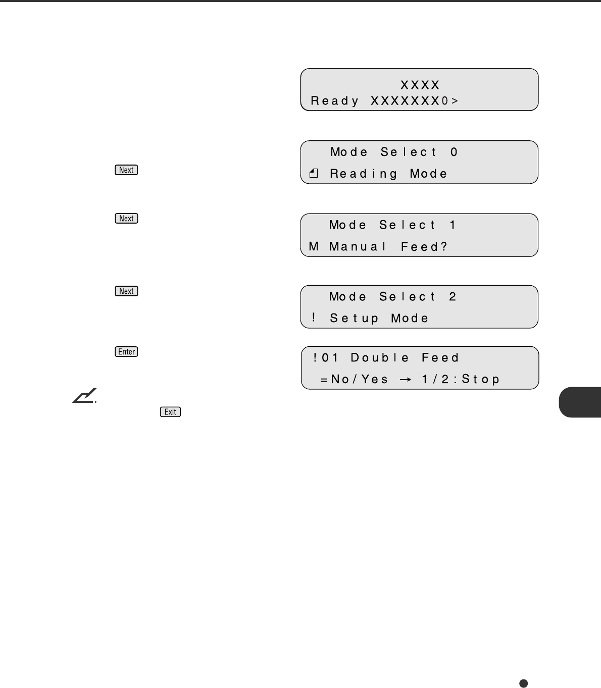
<Screen M1>
1Turn the power On. Then the scanner
displays “Scanner Ready” on the LCD.
<Screen M2>
2If the scanner does not have a video
interface option, go to the procedure step 3.
Press then the scanner with the video
interface option displays Screen M2.
<Screen M3>
3Press then the scanner displays
Screen M3.
<Screen M4>
4Press then the scanner displays
Screen M4.
<Screen 41>
5Press . Now the scanner is at Screen
41 (page 7-4) in Setup mode.
NOTICE
Any time you press , you can return to the “Scanner Ready” screen.

7-2
Contents of the Setup Mode
This section describes the contents of the setup mode.
NoItem Description Selectable
parameters Default
1 Double feed check Specifies the double feed detection. Double
feed is detected by checking the document
length and/or paper thickness.** No/Yes No
2Length check
=No/10/15/20 mm
Specifies the document length to enable
double feed detection sets the document
length.
Tolerance:
No/10/15/20mm No
3 IPC pre-setting
Scanner automatically sets the
recommended reading parameters. 3 sets
of parameters are available when IPC-4D is
not installed.
Document:
No
1: Sharpen
2: Darken Character
3: Copy Quality
No
4Resetting of
abrasion counter Resets the abrasion counter. --- ---
5Pick start time
setting
Specifies the time from document Insertion
to the start of picking. User can select the
most comfortable Pick start time for the job.
Time:
0.2 to 29.8 sec 1.0 sec
6 Time-out limit setting Specifies the time the scanner waits for the
next document insertion after the last
document was scanned.
Time:
27 values from
1 to 1999 sec 30 sec
7 ADF offset setting* Specifies the horizontal and vertical offset
of the image when using the ADF.
Offset:
H:-2 to +3 mm
V:-2 to +3 mm
Offset:
H: 0 mm
V: 0 mm
8Flatbed offset
setting* Horizontal and vertical offset of the FB
image is specified.
Offset:
H:-2 to +3 mm
V:-2 to +3 mm
Offset:
H: 0 mm
V: 0 mm
9Option (IPC/Imprinter)
status display
Displays the type (IPC-4D) of the IPC
option. "IPC PRT" is displayed when the
fi-475PR Imprinter Option is installed. --- ---
10 SCSI ID setting The SCSI ID is selectable. Note that the
new setting is made valid after power is
turned off and on again.
SCSI ID:
0/1/2/3/4/5/6/7 5
11 SCSI terminator
setting Switches the SCSI terminator On/Off. On/Off On
12 Low Power Mode
setting Changes the default setting of the duration
for power save. 5 min.
to 60 min. 15 min.

7-3
(Continued)
* This offset refers to the difference from the value adjusted by automatic offset adjustment.
** Some restrictions apply to the detection of a double feed.
NoItem Description Selectable
parameters Default
13 Select Interface Selects the interface when the scanner has
a board in the Third Party Slot. Auto/SCSI/TPS Auto
14 Display TPS Board
ID Number Displays the ID number of the board which
is installed in the Third Party Slot. --- ---
15 IPC mode
When the IPC-4D image processing board
is installed in the third party Slot, select this
IPC-4D board or the image processing
circuit built in the scanner.
Scanner/IPC4D Scanner
16 ADF Edge Erasing Adjusts the edge areas to be erased from
the image scanned by the automatic
document feeder (ADF).
Left/Right:
0 to 15 mm
Top:
0 to 15 mm
Bottom:
-7 to +7 mm
Left/Right:
0 mm
Top:
0 mm
Bottom:
0 mm
17 FB Edge Erasing Adjusts the edge areas to be erased from
the image scanned by the flat bed (FB).
Left/Right:
0 to 15 mm
Top:
0 to 15 mm
Bottom:
0 to 15 mm
Left/Right:
0 mm
Top:
0 mm
Bottom:
0 mm
18 Ink Remain Resets the ink remain counterr. Reset/No No
19 Numbering Print Enables or disables the numbering counter
when the fi-475PR Imprinter is installed. On/Off Off
7-4
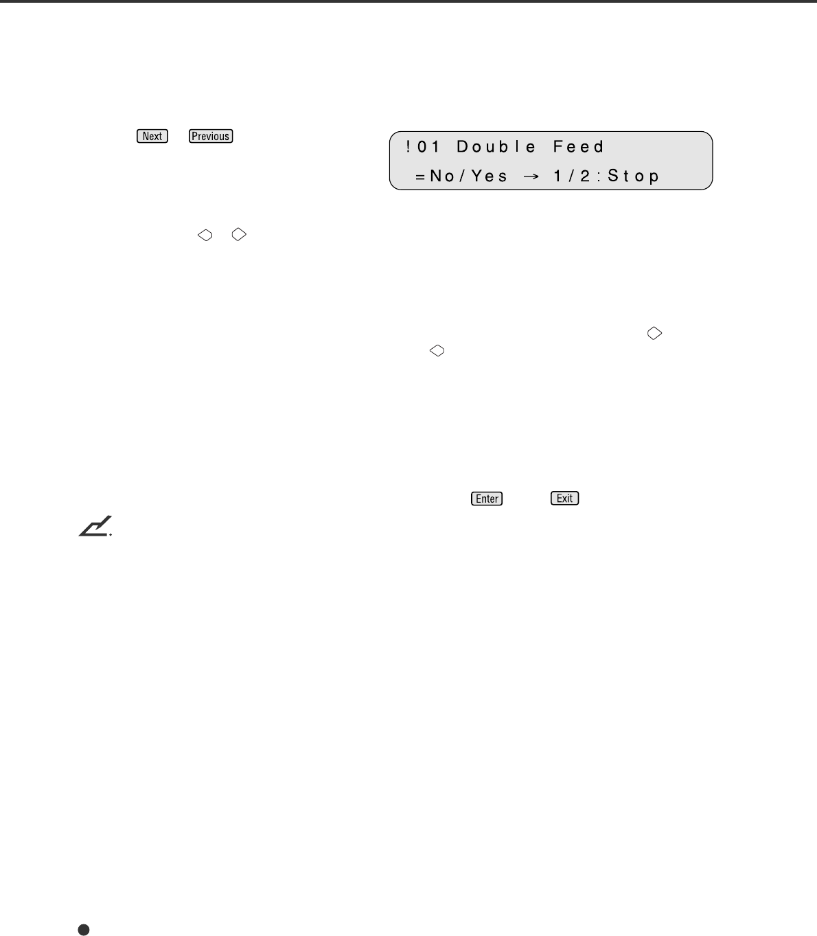
1. Setting double feed detection (Paper Thickness)
When you set the use of double feed detection, you must set it as follows:
<Screen 41>
1Press or and let the scanner
display Screen 41.
2At Screen 41.
Press either the or button to set the double feed detection according to the paper thickness
(transmitted light).
The paper thickness is checked using the difference between two consecutive sheets of paper fed
from the ADF. On this screen, select whether or not to check for double feeding, and select the error
processing.
Each time either of these buttons is pressed, the location of the blinking moves. When the button is
pressed, the blinking moves from (1) to (3). When the button is pressed, the blinking moves in the
opposite direction. However, if the setting by the host computer is valid, the location of the blinking
does not move when either button is pressed.
(1) “No” is blinking: Paper thickness is not checked.
(2) “Yes” and “1” are blinking: Paper thickness is checked. However, a detected double feed
error is displayed on the screen only; processing is continued.
(3) “Yes” and “2: Stop” are blinking: Paper thickness is checked. When the double feed error is
detected, the scan processing is stopped. The error is then
reported to the host.
If you want to disable the double feed, select “No” then press . Press to return.
NOTICES
1. Double Feed detection might have better results when both the paper thickness and the paper length
are used.
2. When the document in ADF is not the double fed document, the previous document might be double
fed, in case the scanner stops feeding by using the double feed detection.
3. Depending on the type of printing on the document, a double feed may not be detected by the paper
thickness.
7-5
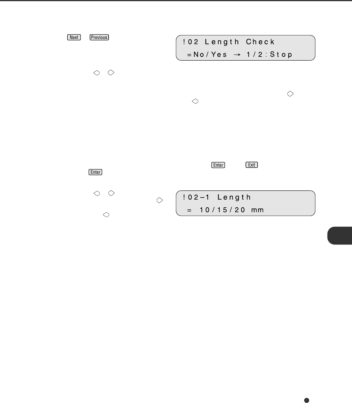
2. Setting double feed detection (Paper Length)
<Screen 42>
1Press or and let the scanner
display Screen 42.
2Press either the or button to set double feed detection according to paper length. The paper
length is checked using the difference between two consecutive sheets of paper fed from the ADF.
Each time either of these buttons is pressed, the location of the blinking moves. When the button is
pressed, the blinking moves from (1) to (3). When the button is pressed, the blinking moves in the
opposite direction. However, if the setting by the host computer is valid, the location of the blinking
does not move when either button is pressed.
(1) “No” is blinking: Paper length is not checked.
(2) “Yes” and “1” are blinking: Paper length is checked. However, a detected double feed error
is displayed only on the screen; processing is continued.
(3) “Yes” and “2: Stop” are blinking: Paper length is checked. When the double feed error is
detected, the scan processing is stopped. The error is then
reported to the host.
If you want to disable the double feed, select “No” then press . Press to return.
After pressing , the scanner displays the screen 42-1.
<Screen 42-1>
3Press either the or button to set double
feed detection (paper length). When the
button is pressed, the blinking moves from
(1) to (3). When the button is pressed, the
blinking moves in the opposite direction.
(1) The “10” is blinking: Threshold is 10mm
(2) The “15” is blinking: Threshold is 15mm
(3) The “20” is blinking: Threshold is 20mm
7-6
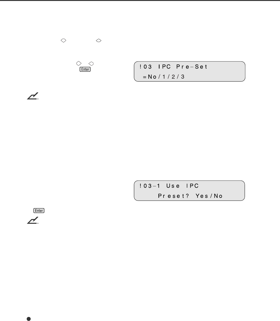
3. Setting IPC pre-set mode
When you set the use of the IPC pre-set mode, you must set it as follows:
1Press “Next” or “Previous” and let the
scanner display Screen 43.
<Screen 43>
2At Screen 43, press or to select the
pre-Setting and press to activate the
pre-setting. Then the scanner displays
Screen 43-1.
NOTICES
The following IPC pre-settings can be selected when IPC-4D is installed:
Preset 1: Captures texts printed on the colored background
Preset 2: Produces an image with good contrast
Preset 3: OCR Smoothing
Preset 4: Image Smoothing
Preset 5: Dither
Preset 9: Suitable for pre-printed paper (color)
Preset 10: Suitable for carbon paper
The following built-in IPC pre-settings can be selected even though IPC-4D is not installed:
• Sharpen
• Darken Character
• Copy Quality
<Screen 43-1>
3At Screen 43-1, select “Yes” or “No”. Note
that when you select “Yes”, the IPC setting
from the Host computer is ignored. If you
select “No”, the IPC setting will be changed
according to the host setting. Finally press
.
NOTICE
When you select the Copy Quality, select the scanner and printer settings carefully to get the best quality.
7-7
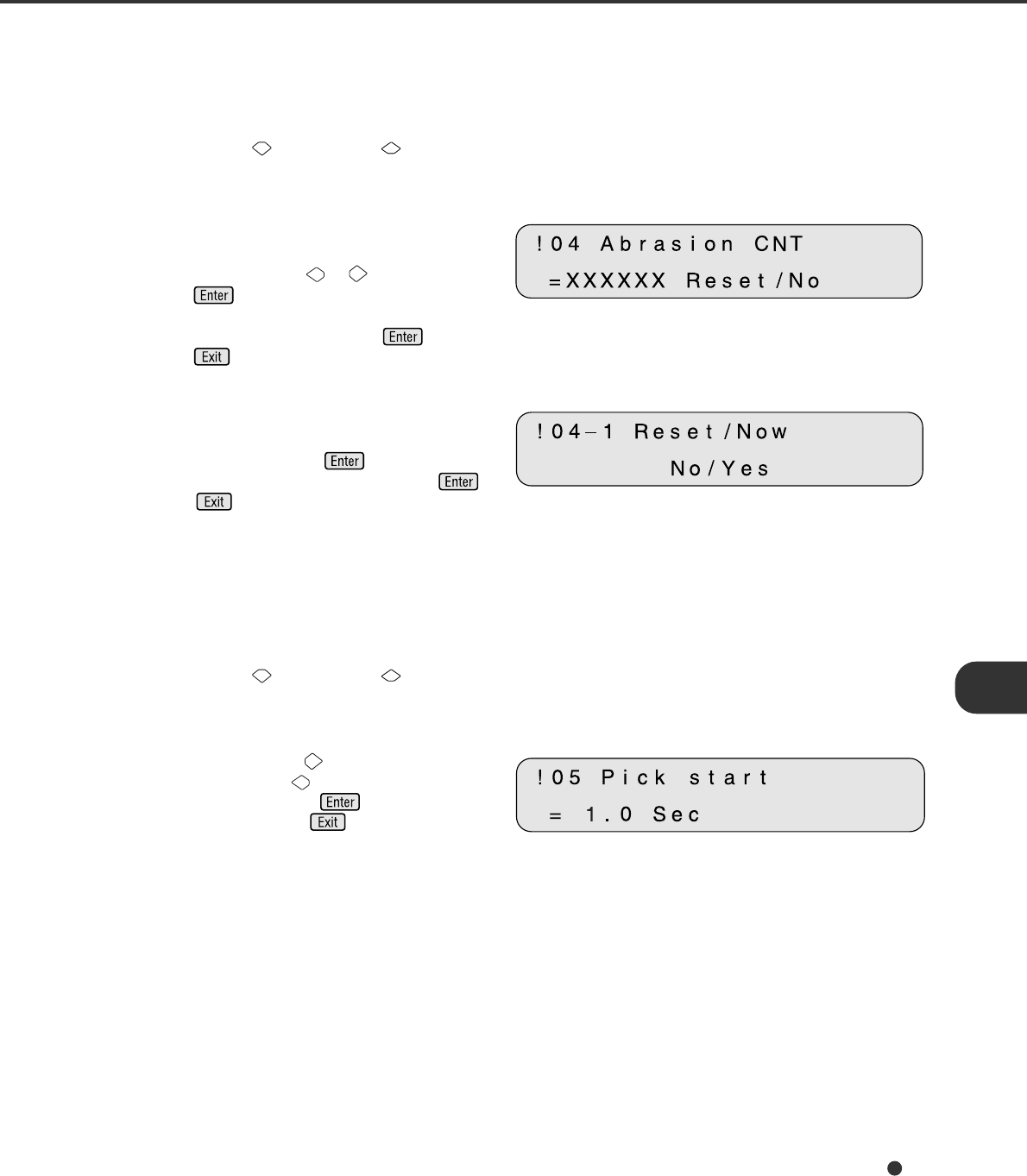
4. Reset of the abrasion counter
When you reset the abrasion counter, you must set it as follows:
1Press “Next” or “Previous” and let the
scanner display Screen 44.
<Screen 44>
2At Screen 44;
If you want to reset the abrasion counter,
select “Yes” through or button and
press . Go to procedure 3.
If you do not want to reset the abrasion
counter, select “No” and press . Finally
press to return.
<Screen 44-1>
3At Screen 44-1;
If you want to reset the abrasion counter,
select “Yes” and press . If you do not
want to reset it, select “No” and press .
Press to return.
5. Setting the pick start time
When you set the pick start time, you must set it as follows:
1Press “Next” or “Previous” and let the
scanner display Screen 45.
<Screen 45>
2At Screen 45, press to increase the Pick
start time or press to decrease the Pick
start time. Then press to activate the
setting. Finally press to return.
7-8
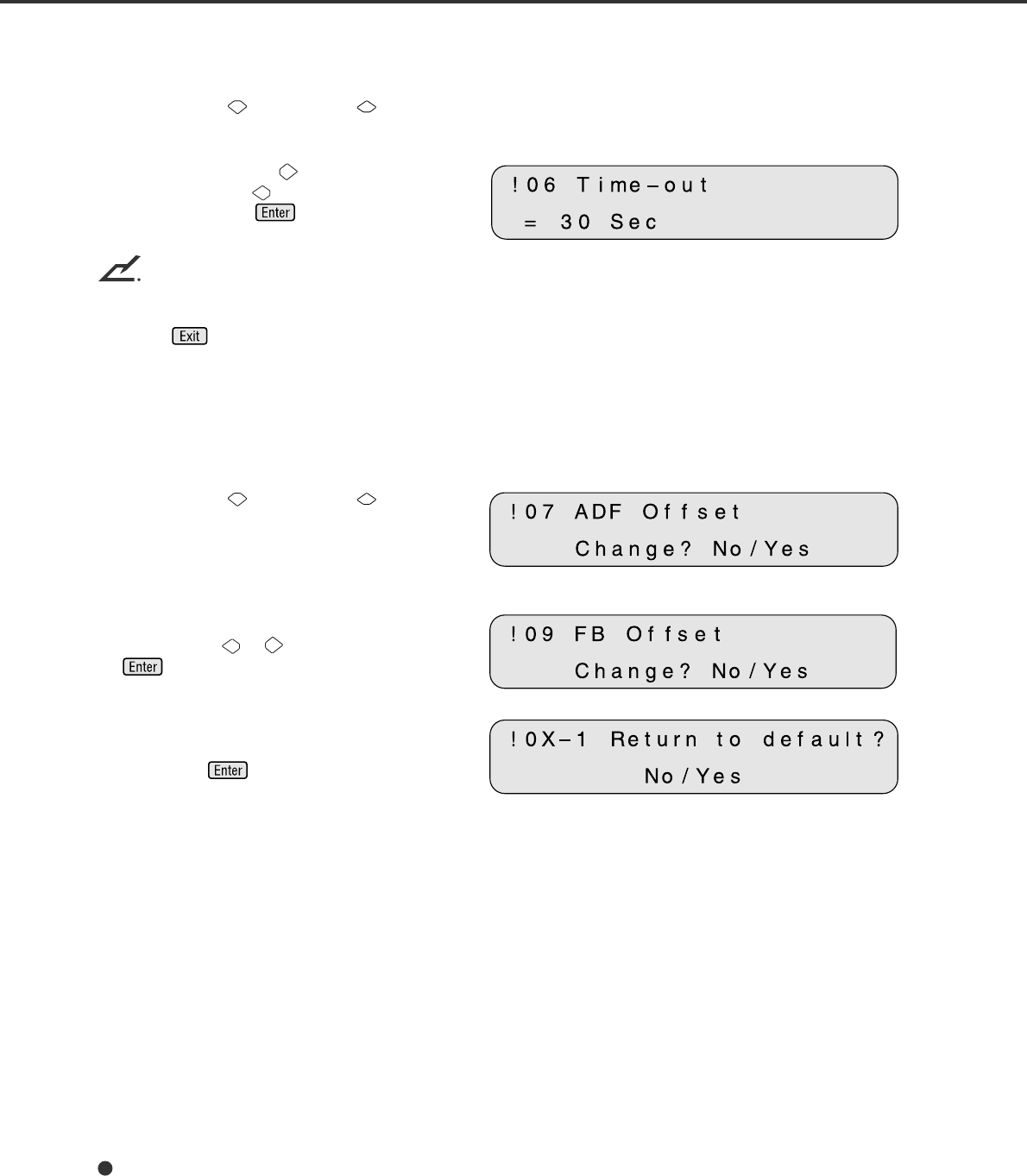
6. Setting the time-out limit
1Press “Next” or “Previous” and let the
scanner display Screen 46. <Screen 46>
2At Screen 46, press to increase the
number or press to decrease the time-out
limit. Then press to activate the
setting.
NOTICE
Default is 30 seconds.
3Press to return.
7. ADF Offset Setting
8. Flatbed Offset Setting
<Screen 47>
1Press “Next” or “Previous” and let the
scanner display the following:
• Offset of the ADF: Screen 47.
• Offset of the Flatbed: Screen 48.
<Screen 48>
2At Screen 47, 48, or 49, select “Yes” by
pressing the or button, then press
. The scanner displays Screen A. (X =
7 or 9) <Screen A>
3At Screen A, if you want to let the offset
return to default, select “Yes” otherwise “No”
then press . The scanner displays
Screen B.
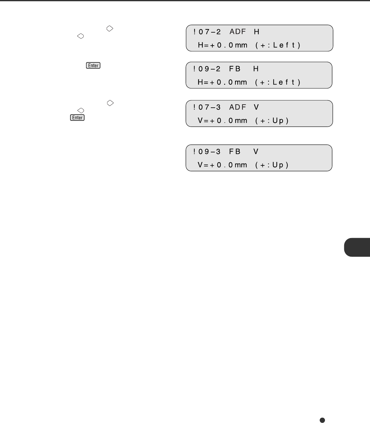
7-9
<Screen B (Example of ADF Offset)>
4At Screen B, press to increase the offset
or press to decrease offset.
The increment or decrement is 0.5 mm.
<Screen B (Example of FB Offset)>
Then press to activate the setting. The
scanner displays Screen C.
<Screen C (Example of ADF Offset)>
5At Screen C, press to increase the offset
or press to decrease the offset. Then
press to activate the setting. The
scanner displays the next item of the setup
mode. <Screen C (Example of FB Offset)>
7-10
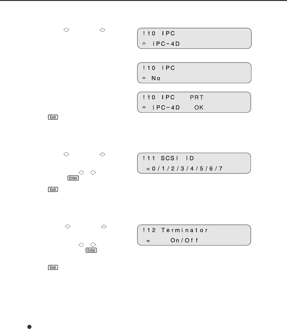
9. Option (IPC/Imprinter) Status Display
<Screen 49>
1Press “Next” or “Previous” and let the
scanner display Screen 49.
2Screen 49 indicates that the IPC-4D option is
installed. <Screen 49-1> (An example)
Screen 49-1 indicates that the IPC-4D option
is not installed.
<Screen 49-2> (An example)
Screen 49-2 indicates that the IPC-4D option
and the fi-475PR (Imprinter) option are
installed.
3Press to return.
10. SCSI ID Setting
<Screen 50>
1Press “Next” or “Previous” and let the
scanner display Screen 50.
2At Screen 50, press or to select SCSI
ID. Then press to activate the setting.
3Press to return.
11. SCSI Terminator Setting
<Screen 51>
1Press “Next” or “Previous” and let the
scanner display Screen 51.
2At Screen 51, press or to select
Terminator. Then press to activate the
setting.
3Press to return.
7-11
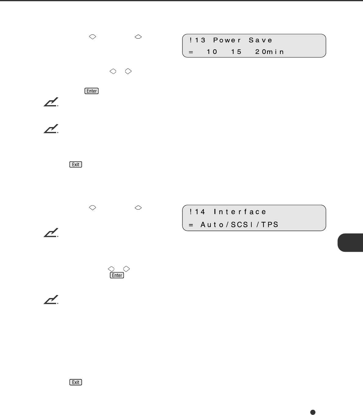
12. Low Power Mode Setting
<Screen 52>
1Press “Next” or “Previous” and let the
scanner display Screen 52.
2At Screen 52, press or to select the
time duration. A minimum of 5 min to the
maximum of 60 minutes can be selected.
Then press to activate the setting.
NOTICE
At screen 52, “No” does not mean that you can turn off the “Low Power Mode” (Power Save Mode). You
cannot disable the Power Save Mode.
NOTICE
The default time recommended by the ENERGYSTAR® program is 15 minutes. The default for the fi-4640S
scanner is 15 minutes, as recommended.
3Press to return.
13. Select Interface
<Screen 53>
1Press “Next” or “Previous” and let the
scanner display Screen 53.
NOTICE
The screen 53 will appear oniy when the scanner has proper interface boards or option boards in the third
party slot.
2At Screen 53, press or to select the
interface type. Press if you want to
change the setting.
NOTICES
1. Normally, this setting does not have to be changed.
2. When an appropriate board is installed in the third party slot of the scanner, the scanner automatically
turns off the SCSI interface, activating the board in the third party slot. Screen 53 can be used to
forcibly change the selected interface. The selected interface is then forcibly changed.
3. The SCSI interface and the board installed in the third party slot cannot be used at the same time.
4. The default is Auto.
3Press to return.
7-12
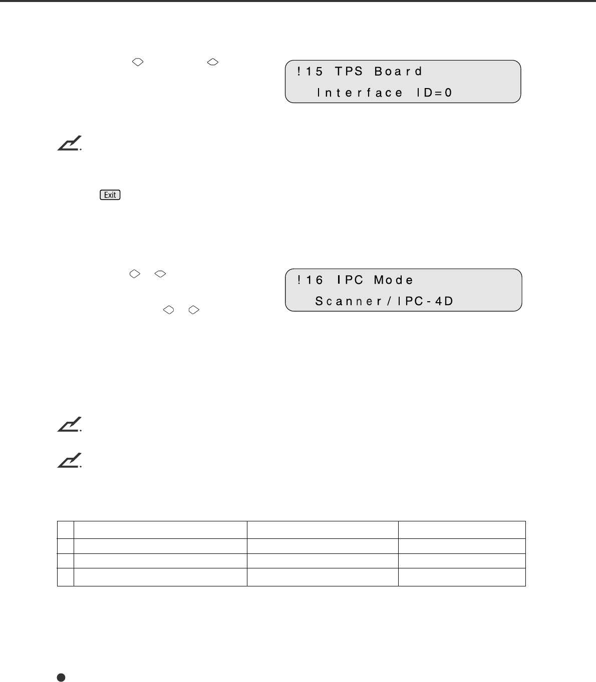
14. Display the TPS Board ID Number
<Screen 54> (An Example)
1Press “Next” or “Previous” and let the
scanner display Screen 54.
The scanner displays the ID number if the
applicable board is installed.
NOTICE
If the video interface board is installed properly, the display shows “ID=7”.
2Press to return.
15. Select Built-In/IPC-4D Image Processing
<Screen 55>
1Press “Next” or and let the scanner
display the Screen 55.
2At Screen 55, press or to select
“Scanner” or “IPC-4D”.
When “Scanner” is selected, the scanner
uses its built-in image processing. On the
other hand, the scanner uses the image
processing of the IPC-4D when the IPC-4D is
installed and “IPC-4D” is selected.
NOTICE
The factory default is “Scanner”.
NOTICE
fi-4640S has built-in Image Processing. The following image processing is supported both by the fi-4640S
and the IPC-4D. As a default, the scanner built-in functions are enabled. By setting “On” using the
Operator Panel, the IPC-4D image processing overrides the built-in functions.
Image Processing IPC-4D fi-4640S
1 Emphasis/Smoothing 5 x 5 matrix 3 x 3 matrix
2 Outline Pre-threshold Laplacian Laplacian
3 Simplified Dynamic Threshold IPC-2 like SDTC 3 x 3 max-min
The functions of the IPC-4D are intended for compatibility with those of the IPC-3/3D (except for image
quality). The matrix size used in the IPC-4D is larger than the one in the fi-4640S. The fi-4640S Built-in
Dynamic Threshold is a new algorithm.
7-13
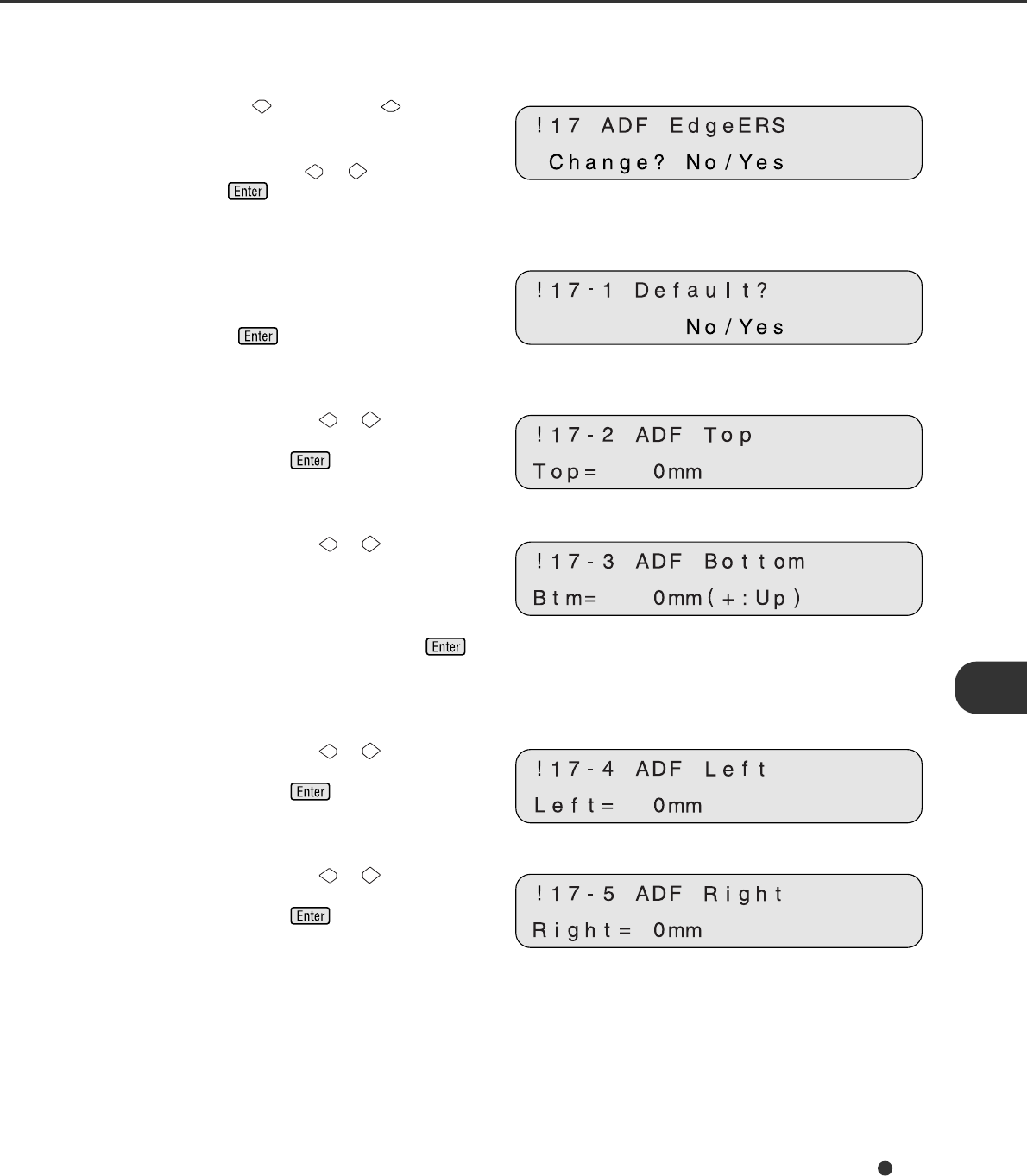
16. Adjust ADF Erasing Edges
<Screen 56>
1Press “Next” or “Previous” and let the
scanner display Screen 56.
2At Screen 56, press or to select “Yes”
and press . Then the scanner displays
Screen 56-1.
<Screen 56-1>
3At Screen 56-1, select “Yes” to return the
settings to the factory default or select “No”
to make new settings (as shown below).
Then press . The scanner displays
Screen 56-2.
<Screen 56-2>
4At Screen 56-2, press or to change the
top setting. The value changes in 1 mm
units. Then press to activate the
setting. The scanner displays Screen 56-3.
<Screen 56-3>
5At Screen 56-3, press or to change the
bottom setting. With (+:Up), the area is set
upward from the bottom edge of the image.
With (–:Down), the area is set downward from
the bottom edge of the image. The value
changes in 1 mm units. Then press to
activate the setting. The scanner displays
Screen 56-4.
<Screen 56-4>
6At Screen 56-4, press or to change the
left setting. The value changes in 1 mm
units. Then press to activate the
setting. The scanner displays Screen 56-5.
<Screen 56-5>
7At Screen 56-5, press or to change the
top setting. The value changes in 1 mm
units. Then press to activate the
setting. The scanner displays the next setup
item.
7-14
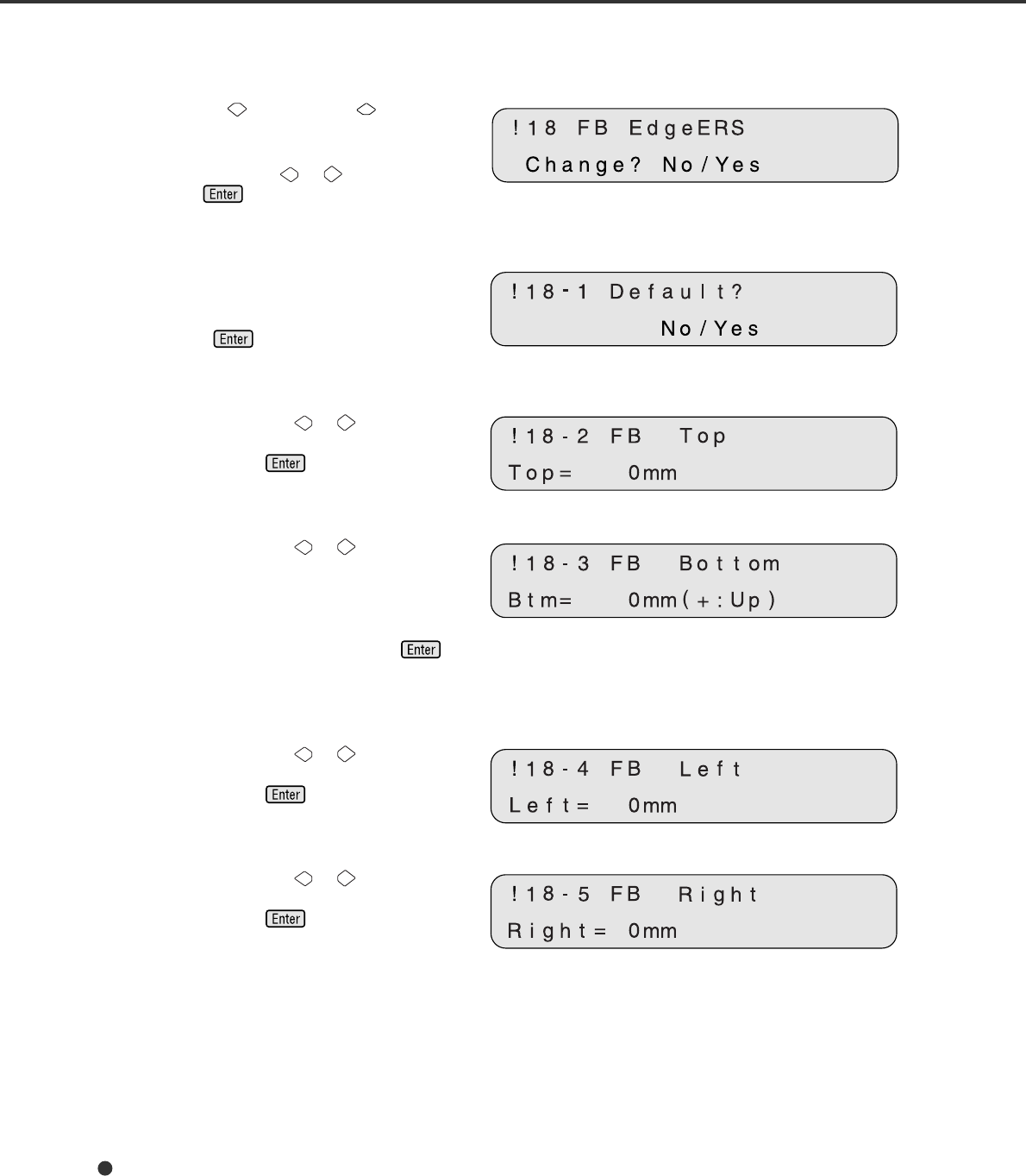
17. Adjust FB Erasing Edges
<Screen 57>
1Press “Next” or “Previous” and let the
scanner display Screen 57.
2At Screen 57, press or to select “Yes”
and press . Then the scanner displays
Screen 57-1.
<Screen 57-1>
3At Screen 57-1, select “Yes” to return the
settings to the factory default or select “No”
to make new settings (as shown below).
Then press . The scanner displays
Screen 57-2.
<Screen 57-2>
4At Screen 57-2, press or to change the
top setting. The value changes in 1 mm
units. Then press to activate the
setting. The scanner displays Screen 57-3.
<Screen 57-3>
5At Screen 57-3, press or to change the
bottom setting. With (+:Up), the area is set
upward from the bottom edge of the image.
With (–:Down), the area is set downward from
the bottom edge of the image. The value
changes in 1 mm units. Then press to
activate the setting. The scanner displays
Screen 57-4.
<Screen 57-4>
6At Screen 57-4, press or to change the
left setting. The value changes in 1 mm
units. Then press to activate the
setting. The scanner displays Screen 57-5.
<Screen 57-5>
7At Screen 57-5, press or to change the
top setting. The value changes in 1 mm
units. Then press to activate the
setting. The scanner displays the next setup
item.
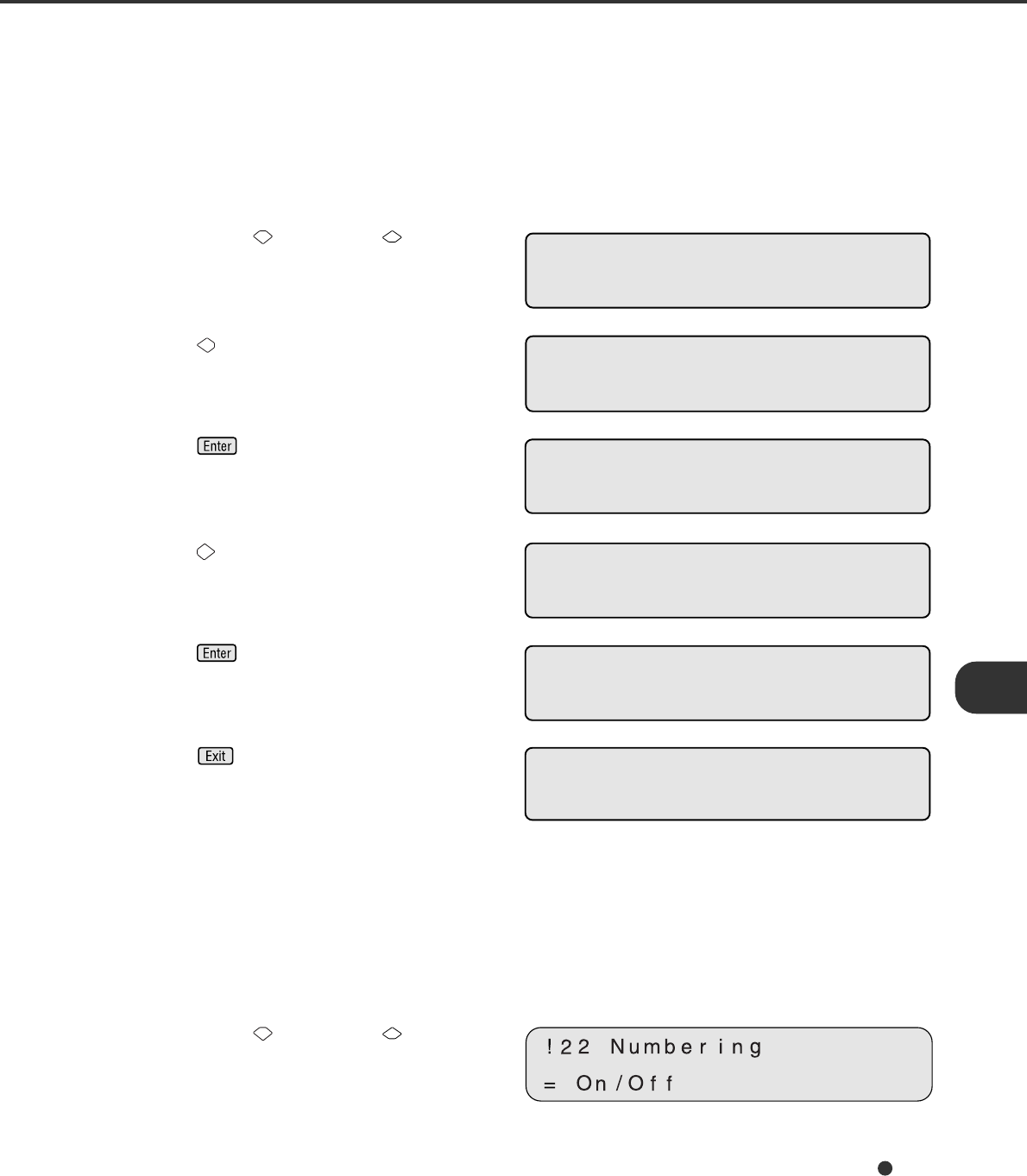
7-15
<Screen 58>
1 Press “Next” or “Previous” and let the
scanner display Screen 58. First, “No” blinks.
<Screen 58-1>
2 Press , then “Reset” blinks. (Screen 58-1)
<Screen 58-2>
3 Press . The reset execution screen
appears. First, “No” blinks. (Screen 58-2)
<Screen 58-3>
4 Press , then “Yes” blinks. (Screen 58-3)
<Screen 58-4>
5 Press to perform reset operation.
The ink remain indicator returns to
nnnnnn. (Screen 58-4)
6 Press .
The LCD returns to the “Ready” screen.
19. Setting the Numbering Print Function (for fi-475PR Imprinter Option)
You can specify conditions of the numbering print function from the operator panel when the scanner is
equipped with the fi-475PR imprinter. The numbering counter increments 1 each a sheet of paper is read.
Numbering print starts with a top margin of 42 mm. <Screen 59>
1Press “Next” or “Previous” and let the
scanner display Screen 59.
18. Reset of the Ink Remain Counter
The ink remain counter checks the service life of the print cartridge and makes a message “Please a new
Ink” to prompt you to prepare a new ink cartridge. When the imprinter cannot print any more, replace the
print cartridge and reset the Ink remain counter as follows. You must reset the ink remain counter even if
you replace the print cartridge before its service life.
!21–1 Rese t Now
No /Yes
!21 Ink remain
=nqqqqq Rese t /No
!21 Ink remain
=nqqqqq Rese t /No
!21–1 Rese t Now
No /Yes
!21 Ink remain
=nnnnnn Rese t /No
XXXX
Read y XXXXXXX0
>
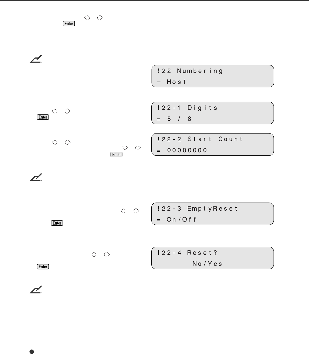
7-16
2At Screen 59, press or to select “On”
then press if you want to activate the
setting function. The scanner displays
Screen 59-1, indicating that the setting
function is activated.
NOTICE
When the setting function is disabled, the screen
is as shown right.
<Screen 59-1>
3At Screen 59-1, select the number of digits.
Press or to select “5” or “8” then press
. The scanner displays Screen 59-2.
<Screen 59-2>
4At Screen 59-2, select the initial number.
Press or to move the place of the
blinking (changeable) digit and press or
to change the value, then press . The
scanner displays Screen 59-3.
NOTICE
The possible maximum number is 99999 (for five digits) or 16777215 (for eight digits).
<Screen 59-3>
5At Screen 59-3, specify whether the number
is initialized at hopper empty. Press or
to select “On” if you want to initialize, then
press . The scanner displays Screen
59-4.
<Screen 59-4>
6At Screen 59-4, specify whether the number
is reset at once. Press or to select
“yes” if you want to reset at once, then press
. The scanner terminates the setup
mode.
NOTICE
The command from the host computer overrides the specification of the operator panel. When the host
computer issues a command disabling the specification of the operator panel, Screen 59-4 does not
appear.

GL-1
GLOSSARY OF TERMS
A4 size
A standard paper size. Paper size is 210 x 297 mm.
A5 size
A standard paper size. Paper size is 148 x 210 mm.
A6 size
A standard paper size. Paper size is 105 x 148 mm.
A7 size
A standard paper size. Paper size is 74 x 105 mm.
A8 size
A standard paper size. Paper size is 53 x 74 mm.
Abrasion counter
Counts the cumulative number of documents read to indicate when belts/rollers should be replaced. The
number of read documents accumulates until an operator resets the counter. The counter should be reset
when these consumables are replaced.
ASCII
The acronym for American Standard Code for Information Interchange.
ASCII is a set of 256 codes (numbered 0 to 255) used to communicate information between a computer
and another device such as a scanner.
Automatic separation
An image processing method in which the scanner automatically detects difference between text and
photos, and chooses the threshold accordingly. Automatic separation allows the scanner to switch
between line mode and half tone mode in one pass.
Automatic start mode (<-> manual start mode)
In this mode, the reading operation is activated only by issuing the the START command.
Backside reading = Back-side scanning
Refers to reading the backside of the document, specifically in Duplex reading mode.
Bit
The smallest unit of information in computer memory. A bit is a single digit, either a 1 or a 0, in the binary
numbering system. Eight bits equal one byte.
Density
In this manual, refers to a measurement of the depth of the display.
Dither
Technique for producing halftone images by representing the entire grayscale with only two pixel levels,
black and white.

GL-2
Double feed detection
A scanner function which detects the accidental feeding of multiple sheets by the ADF unit. Can be turned
on or off by the operator.
Double Letter Size
A standard paper size used in the U.S.A. and othe countries. Paper size is 11 x 17 inches.
dpi
Dots per inch.
Dropout color
A color which is used in the document but does not appear in the read image.
Duplex reading mode
A reading mode in which both sides of the document are read.
Equipment Error
An error that cannot be corrected by the operator. Call CE.
Error diffusion
High-quality halftone (pseudo-grayscale) image production based on black-and-white pixel binarization. A
pixel’s optical density and that of adjacent pixels are summed, with black pixels relocated in their order of
density as they relate to adjacent pixels.
The purpose of this technique is to minimize the average error between read and printed densities. Den-
sity data for adjacent pixels is modified by diffusing errors on the objective pixel into several pixels, which
are then binarized. This maintains high grayscale levels and resolution during reading, while suppressing
more patterns by dotted halftone images such as newspaper photographs.
FB
In this manual, FB means flat bed.
Filtering
A correction method that improves the read quality of handwritten documents. The read quality of images
written in pencil or ball-pointed pen depends on the reflective light characteristics of the specific ink or
lead used. Dropped pixels may produce outlines, gaps, or thin, barely connected lines due to uneven
optical density. Filtering detects areas lighter than their surroundings and increases their density to
improve image clarity.
Front-side reading = Front-side scanning
Refers to reading the front side of the document, specifically in Duplex reading mode.
Halftone processing
Any method used to reproduce a photograph which includes a shade as an image composed of dots,
namely, a binary image. Dithering and error diffusion processing are examples of halftone processing.

GL-3
Hexadecimal
A base-16 numbering system (also commonly referred to as hex numbers). Since a base-16 system
requires 16 digits, numbers 0 through 9 and letters A through F are used. It is convenient to express
binary numbers in hexadecimal because fewer digits are required.
Image emphasis
Density is decreased for lighter but not completely white areas adjacent to black areas. Weakening this
emphasis eliminates spot noise or produces softened images.
Image processing
An image is read with specified parameters.
Interface
The connection that allows communication from one part of a system to another. For example, electrical
signals are transferred between the computer and scanner over an interface cable.
Inversion (Reverse-image reading)
In reverse-image reading, data is changed from black to white and vice versa.
IPC preset mode
While reading binary images, it is necessary to set the scanner according to the quality of the sheet to be
read. In this mode, these settings can be performed in advance by corresponding each setting to a
pattern number.
IPC-4D
Image processing option of this scanner.
IRAS
Initialization of the hardware.
Landscape orientation
A document is transported and read with the long side vertical to the moving direction.
Letter size
A standard paper size used in the U.S.A. and other countries. Paper size is 8-1/2 x 11 inches.
Linedrawing mode
Selecting linedrawing mode makes threshold and contrast settings effective but prevents brightness from
being set. The specified threshold value determines whether black or white pixels are scanned. Line
drawing mode is therefore appropriate for scanning text and line art images.
Manual Feed mode = Manual Mode
Requires the operator to feed each document manually into the ADF paper chute.
Manual start mode (<-> automatic start mode)
The reading operation is activated by pressing the START button in this mode. Available only when video
option board is installed.

GL-4
Mirror image
The read image is symmetrically flipped to produce a mirror image of the original detected in the main
scanning direction.
Noise removal
Isolated noise from an image appearing as black spots in white areas and voids in black areas is removed
to improve image quality.
Operator panel
A panel containing the scanner indicators and buttons. The operator panel is used to control scanner
operations such as loading document, selecting features, and changing setup options.
Outline extraction
The boundary between black and white areas is traced and the outline extracted for closed areas.
PAPER JAM
A warning informing the user that document is jammed in the transport unit, or that transportation is
disabled because the transport unit is slippery. This warning also appears when a double feed is de-
tected.
Photograph mode (White level follower OFF)
Selecting photograph mode makes brightness and contrast settings effective but prevents the threshold
from being set. With photograph mode, the darkness of image corresponds to the black-pixel density,
making it suitable in scanning images such as photographs having gradations.
Photo mode = photograph mode
A photograph is read properly in this mode.
Pick start time
The period from the manual insertion of the document until picking starts after the document passes the
hopper empty sensor.
Portrait orientation
A document is transported and read with the long side parallel to the moving direction.
Paper counter
Indicates the total number of read document from start of reading until the hopper becomes empty.
Read operation
Refers to the reading operation including Simplex reading and Duplex reading.
RS-232C interface
A type of serial interface. See Serial interface.
SCSI-ID
Used to specify a particular SCSI device when the initiator selects a target or the target reconnects to the
initiator.

GL-5
Serial interface
A standard computer interface. Information is transferred between devices over a single wire (although
other wires are used for control).
With a serial interface, an interface cable greater than 3 meters (10 feet) can be used. This is often
necessary in networking environments, where the scanner may be shared.
SETUP mode
In this mode, users can view or set a variety of function in off-line.
Simplex reading mode
Only the front side of the document is read in this mode. Place the documents face up at the center of the
hopper table.
Smoothing
A process that eliminates “jaggies” from slanted lines and curves. Irregular convexities are deleted and
irregular concavities filled in. This is useful in OCR applications, for example.
Temporary Error
An error correctable by the operator.
Terminator
Devices with a SCSI interface can be daisy-chained. A resistor that includes terminal circuits needs to be
placed at both ends of a cable when devices are daisy-chained. If a device (such as a scanner) is the last
device in a chain, leaving an interface connector unused, a Terminator theerfore must be attached to
provide those terminal circits.
Third Party Interface
Optional board provided by Fujitsu or interface board provided by a third party can be installed and used.
Time-out limit
This is the time the scanner waits for next document insertion after the last document feeding. The
scanner returns Paper Empty when no document is set after time-out limit.
TPS
Third Party Slot.

GL-6

IN-1
INDEX
Abrasion counter 1-7
Activating the Setup mode 7-1
ADF 1-2, 1-3
ADF
document feeder capacity 4-4
erasing edges 7-3, 7-13
lever 1-2, 1-3
mode 1-9
paper chute 1-2
Alarm 1-10
Ambient condition 5-2
Arrangement 1-5
Assemblies 1-4
Button
/LED Function 1-6
Cable connection 2-4
Check LED 1-6
Checking the components 1-1
Connecting
the interface cable 2-5
the power cable 2-4
Consumables 6-1
Contents of the Setup mode 7-2
Conventions vi
Counter display 1-7
Density 6-5
Dimentions 5-2, 5-3
Document
bed 1-2, 1-3
cover 1-2, 1-3
holding pad 1-2, 1-3
Quality 4-2
Size 4-1
type 3-6, 4-2
Double
feed detection condition 4-7
feed detection setting 7-2, 7-4, 7-5
feed error 1-9
Enter button 1-6
Exit button 1-6
EXT connector 1-2
FB erasing edges 7-3, 7-14
Feeding direction 4-1
fi-475PR option (imprinter) 6-2, 6-8
Grounding color areas 4-6
Guide A assembly 1-4
Halftone processing 6-5
Heat capacity 5-2
Hopper empty 1-9
Image processing circuit 7-3, 7-12
Ink remain counter 7-15
Inspection 2-2
Inspection 2-2
Installation specifications 5-2
Interface connectors 1-2, 1-3
Interface select 7-3, 7-11
IPC
mode select 7-3, 7-12
preset mode setting 7-2, 7-6
IPC-4D option 6-2, 6-7, 7-12
Job separation sheet 4-8
Label
A 2-2
B 2-2
Landscape orientation 6-4
LCD 1-5
LED 1-6
Loading documents
ADF 3-4
Flat bed 3-8
Low power mode
setting 7-3, 7-11
waking up from 3-2
Manual
feed mode 3-3
start mode 1-6
Manuals and driver 1-1
Next button 1-6
Note, Liability iv
Numbering print 7-15
Offset setting 7-2, 7-8
Operation status 1-8
Operator panel 1-2, 1-5
Option 6-2, 6-3, 6-7, 6-8
Option status display 7-2, 7-10
A
B
C
D
E
F
H
I
N
M
L
G
J
O

IN-2
Pad Assembly 1-1, 1-4, 6-1
Paper
counter 1-7
weight 4-2
Perforation areas 4-5
Pick
roller 1-4, 6-1
start time setting 7-2, 7-7
Plain paper 4-2
Portrait 6-4
Power
cable 1-1, 2-4
consumption 5-2
inlet 1-2, 1-3, 2-4
switch 1-2, 1-3, 2-4, 3-1
Precautions 2-1, 4-2
Preface v
Previous button 1-6
Read LED 1-6
Reading
mode 6-4
thick book 3-10
Resetting
abrasion counter 7-2, 7-7
ink remain counter 7-2, 7-15
Resolution 6-4
Scanner 1-1
SCSI ID setting 7-10
SCSI terminator setting 7-10
Select
interface 7-11
IPC mode 7-12
Setting
double feed detection
paper thickness 7-4
paper length 7-5
IPC preset mode 7-6
low power mode 7-11
numbering print function 7-15
0ffset 7-8
pick start time 7-7
SCSI ID 2-7, 7-10
SCSI terminator 2-7, 7-10
time-out limit 7-8
Setup mode 7-1, 7-2
Shipping lock 2-3
Size 6-4
Specifications 5-1, 5-2
Stacker 1-2, 1-4, 2-6
T
S
R
U
Start button 1-5, 1-6
Stop button 1-5, 1-6
Temporary error 1-9
Third party slot 1-2, 1-3
Time-out limit setting 7-2, 7-8
TPS board ID number display 7-3, 7-12
Turning
the power on 3-1
the power off 2-4
Units 1-2
Units and Assemblies 1-2
Video interface option 6-2, 6-3
Weight 5-2
(Left Arrow Key) button 1-6
(Right Arrow Key) button 1-6
(Next) button 1-6
(Previous) button 1-6
(Send To) button 1-6
(Start) button 1-6
(Stop) button 1-6
(Enter) button 1-6
(Exit) button 1-6
P
W
V