Fujitsu Read More... NGMobile Backhaulwp
User Manual: Fujitsu Read More... FNC Resources - White Papers - Fujitsu United States
Open the PDF directly: View PDF ![]() .
.
Page Count: 6
Achieving Smooth Migration to a
Next-Generation Mobile Backhaul Network
FUJITSU NETWORK COMMUNICATIONS INC.
2801 Telecom Parkway, Richardson, Texas 75082-3515
Telephone: (972) 690-6000
(800) 777-FAST (U.S.)
us.fujitsu.com/telecom
1
Current 2G and 3G fiber-fed mobile backhaul networks use highly reliable SONET network elements to
transport DS1 services from cell towers to MSCs effectively. Service providers are using OC-3 and OC-12
circuits to interconnect multiple cell towers in a UPSR, providing non-service-affecting site scalability and
survivability.
Network element hardware and power sources are fully redundant. Network element power supplies
are distributed on individual cards and fed over redundant power buses to eliminate any single point of
failure, yielding 99.999% availability. Scaling the cell tower access capacity adds DS1s until an economical
breakpoint is reached relative to DS3 tariff pricing. Based on DS3 tariffs, a crossover point of five to seven
DS1s justifies a DS3 lease. To facilitate DS3 service access, service providers will add M13 multiplexer
functionality to the optical multiplexer using an external M13 network element or, if using an advanced
MSPP, will install a transmux card emulating the M13.
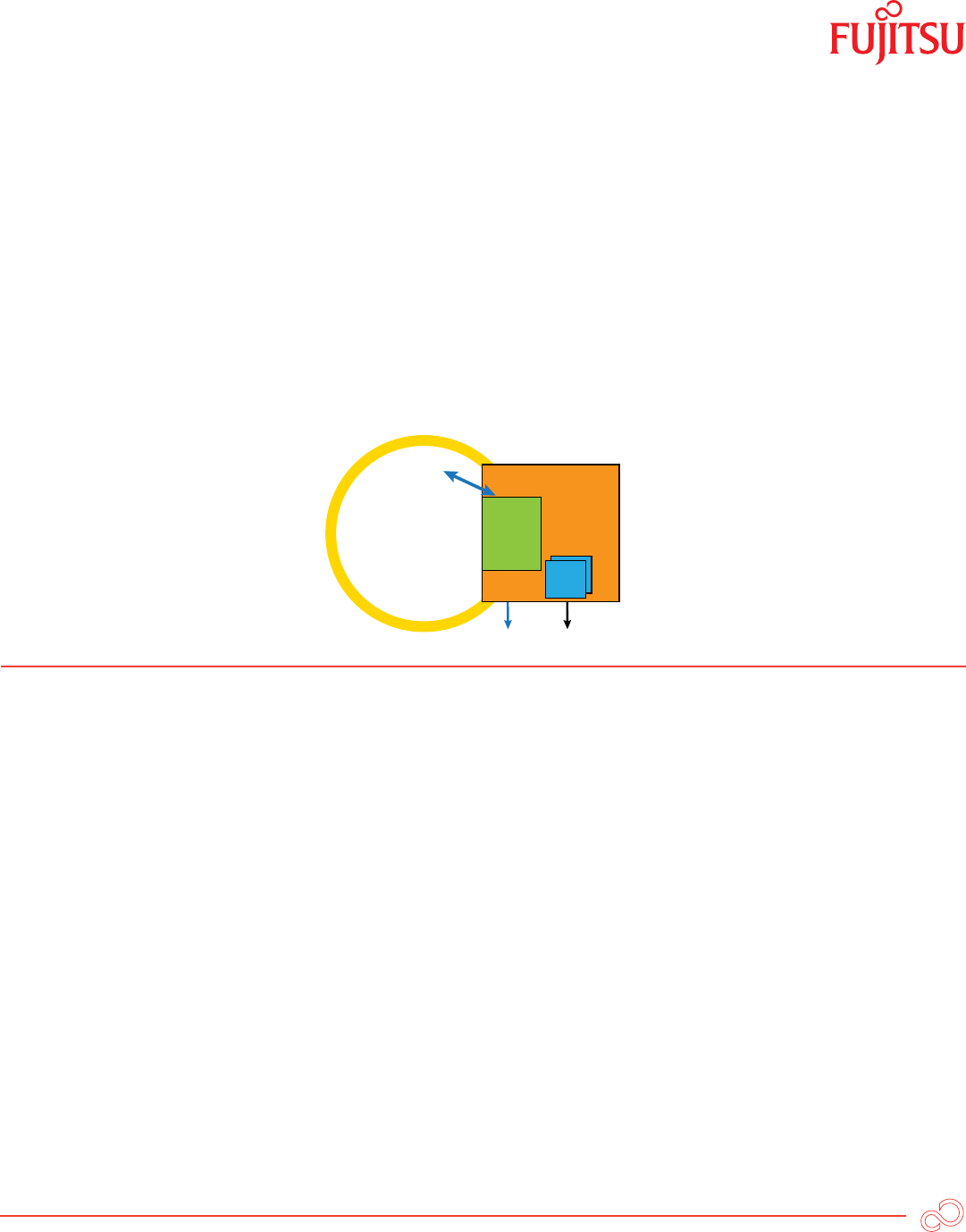
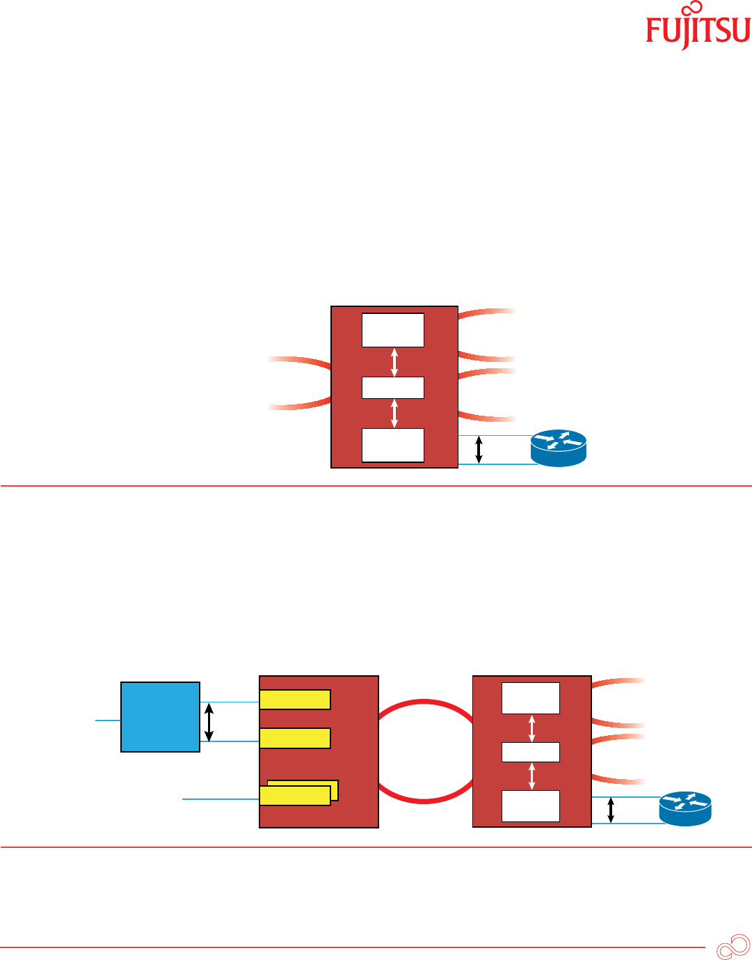
MSPP
DS1
OC-n
MxDS3 or
NxDS1
MxDS3 NxDS1
TMUX
Figure 1: Transmux DS1 Grooming to DS3 Over OC-n
The transmux card grooms the DS1s into a DS3 at the access point, satisfying the DS3 tariff while providing
an economic advantage of 28 DS1 capacity for the price of five to seven. Once groomed, an advanced MSPP
will transport the DS3 directly over the system bus to the OC-n optics, further saving capital expense and
additional equipment to break out and remultiplex the DS3.
As 4G technology becomes available, wireless service providers will upgrade their network for WiMAX and
LTE. Use of 4G radios at cell tower sites requires a transition from DS1 to Ethernet interfaces for backhaul.
OC-n rates at cell sites typically scale to OC-48 once Ethernet traffic is added. Wireless service providers will
transition their equipment over the course of the next several years. Therefore, the wireline service providers
must offer both DS1service for legacy providers and service-aware Ethernet for WiMAX/LTE upgraded
providers.
For your convenience, a list of acronyms can be found at the end of this document.
FUJITSU NETWORK COMMUNICATIONS INC.
2801 Telecom Parkway, Richardson, Texas 75082-3515
Telephone: (972) 690-6000
(800) 777-FAST (U.S.)
us.fujitsu.com/telecom
2
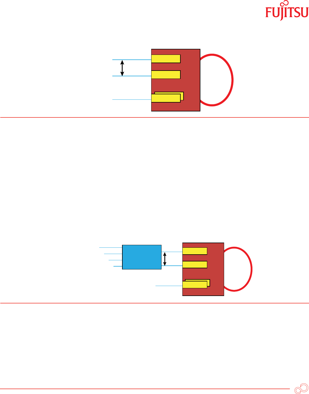
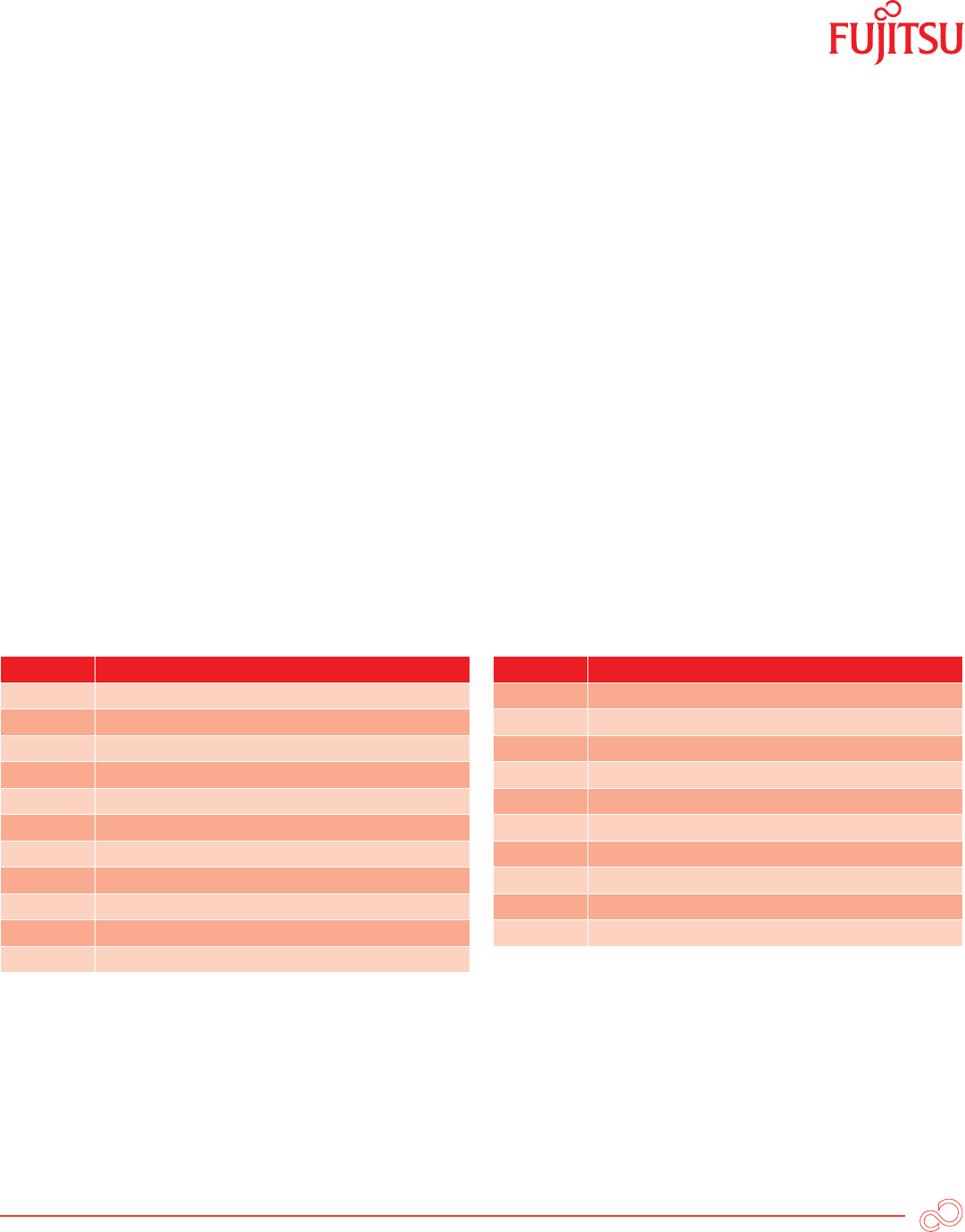
Ethernet
Ethernet
DS1
LAG
Cell Site MSPP
4G Wireless
Service Providers
Legacy Wireless
Service Providers
Figure 2: MSPP at Cell Site with LAG and DS1
Over time, DS1 demand will convert to Ethernet, but that transition period is unclear. To reduce risk, provide
flexibility and maintain installed base investment, wireline service providers will implement a platform
capable of supporting both traditional TDM and service-aware Ethernet through scaling, using GFP-F [1]
plug-in cards as needed. Otherwise, wireline service providers must install new Ethernet-centric equipment
at cell towers where footprint is at a premium, increasing both capital and operational expenses. The 4G
cell site contains a mix of CIR and EIR services and signals to be transported to the MSC. These services may
include VoIP, streaming video, Internet data and telemetry signals. Wireless service providers may use an
L2A [2] to efficiently consolidate these signals at the cell site using various classes of service and statistical
multiplexing. The consolidated L2A is the service port to be backhauled. Since Ethernet traffic at the cell site
is policed using the L2A, the MSPP service port will be all CIR service and transported over an EVC. The EVC
may be duplicated by the wireless service provider at the L2A. The duplicated EVCs are diversely mapped
across the WAN facility by the wireline service provider and service multiplexed at the MSC.
Ethernet
Ethernet
DS1
LAG
Cell Site MSPP
VoIP
High Priority HS Data
Second Priority HS Data
Telemetry
Legacy Wireless
Service Providers
L2A
Figure 3: Cell Site MSPP with L2A Interconnect
FUJITSU NETWORK COMMUNICATIONS INC.
2801 Telecom Parkway, Richardson, Texas 75082-3515
Telephone: (972) 690-6000
(800) 777-FAST (U.S.)
us.fujitsu.com/telecom
3
The MSPP service port interface should offer rate-limiting CIR to backhaul the L2A traffic efficiently.
Maintaining 99.999% reliability for Ethernet service at the cell site requires a similar level of redundancy to
the DS1 hardware method. Use of 802.3ad [3] LAG between the L2A and two service cards within the micro
packet-OTN ensures Ethernet resiliency, effectively providing a 1:1 hardware redundancy, as illustrated in
Figure 3. To ensure maximum end-to-end performance over the WAN, Connection-Oriented Ethernet (COE)
techniques are used within the MSPP or Micro Packet ONP. COE offers deterministic operation, consistently
delivering Ethernet services with the lowest latency, jitter and frame loss. Ethernet service delivered
using COE provides the same performance whether the network has few or many network elements and
regardless of WAN facility fault protection switching.
Maintaining SONET performance at brownfield sites provides carrier-class service capabilities in the access
network. Legacy TDM services are undisturbed, whereas circuit emulation using current techniques over
Layer 2/Layer 3 facilities oversubscribes network bandwidth and has unpredictably high latency and jitter.
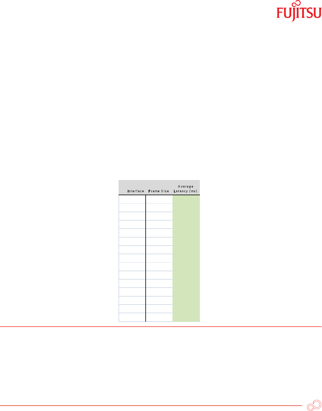
Ethernet CIR traffic over SONET provides COE operation using GFP-F, and realizes one-way latency in the
order of 1.3 milliseconds (worst case) using jumbo frames, as shown in Figure 4. Jitter and frame loss are less
than 125 microseconds and are therefore nonexistent, due to the predictable time-based nature of SONET.
I nt er f a c e F r ame S i z e
A v e r ag e
L a t enc y ( ms )
10 /10 0B ase-T 64 0.0 4
10 /10 0B ase-T 19 2 0.0 6
10 /10 0B ase-T 320 0.0 8
10 /10 0B ase-T 16 0 0 0.2 5
10 /10 0B ase-T 960 0 1.3 2
10 0 B ase-X 64 0.0 4
10 0 B ase-X 19 2 0.0 6
10 0 B ase-X 320 0.0 7
10 0 B ase-X 16 0 0 0.2 4
10 0 B ase-X 960 0 1.31
GigE 64 0.0 4
GigE 19 2 0.0 4
GigE 320 0.0 4
GigE 16 00 0.0 6
GigE 960 0 0 .19
Figure 4: Table of Latency Rates for Ethernet CIR Traffic over SONET using GFP-F
Greenfield networks used for 4G service use micro Packet ONPs at the cell site to transport data services
using COE over OC-48, point-to-point LAG or G.8031 VLAN protected ring topologies up to 10 GbE WAN
facilities. COE over OC-48 offers almost a 2.5 bandwidth increase over GbE access multiplexers.
FUJITSU NETWORK COMMUNICATIONS INC.
2801 Telecom Parkway, Richardson, Texas 75082-3515
Telephone: (972) 690-6000
(800) 777-FAST (U.S.)
us.fujitsu.com/telecom
4
At the MSC, the MSPP TDM traffic is aggregated to a DCS using DS3 or OC-n interconnects. Ethernet traffic
is service-multiplexed [3] providing EVPL [4] connectivity as per MEF-9 from the cell towers. Maintaining
multi-customer service separation and preventing multi-tag duplication in mixed in- and out-of-franchise
networks is solved using 802.1Q [4] VLAN tagging offering pushed, popped or swapped tag treatment.
Odd and even EVCs are service multiplexed on separate ports in dual EVC architectures. These separate
service multiplexed EVC ports presented from the wireline service provides Packet ONP to the wireless
service provider using 802.3ad LAG between two cards of the Packet ONP maintaining high service reliability
just as is used at cell sites.
SONET
Switch
Fabric
Packet
Switch
Fabric
Mapper
Advanced MSPP
SONET IOF
10G Packet
SONET to Cell Sites
LAG
Figure 5: Advanced MSPP Dual Fabric and Mapper
Packet ONPs at the hub and MSC sites have both TDM and packet switch fabric to optimize traffic treatment
with mapping processors to translate between the two. The mapping processor provides a smooth transition
for brownfield sites using SONET to and from packet facilities. This smooth transition allows Packet ONPs to
operate in a SONET network and terminate packet traffic, as well as forwarding to higher-order networks
using 10 Gbps facilities. The higher-order network provision enables gateway operation for future packet-
based network applications.
SONET
Switch
Fabric
Packet
Switch
Fabric
Mapper
Advanced MSPP
SONET IOF
SONET 10G Packet
LAG
Ethernet
Ethernet
DS1
LAG
Cell Site MSPP
4G
Services
Legacy Wireless
Service Providers
L2A
Figure 6: Next-Generation Mobile Backhaul Network
FUJITSU NETWORK COMMUNICATIONS INC.
2801 Telecom Parkway, Richardson, Texas 75082-3515
Telephone: (972) 690-6000
(800) 777-FAST (U.S.)
us.fujitsu.com/telecom
5
Summary
Packet ONPs offer multiservice operation to achieve 99.999% service availability for COE and TDM traffic
backhauling, while providing solutions for greenfield and brownfield backhaul applications. Smooth
transition from legacy SONET to packet functionality enables service providers to reuse legacy networks
to offer advanced data and maintain original TDM services. Packet ONPs with multiple switch fabrics
optimize operations for SONET and packet with mapping translation between them. These architectures
offer seamless migration from present-mode SONET to packet while preserving installed-base investments.
Access networks using Packet ONPs using GbE, OC-48 or 10 GbE for point-to-point or ring protection offer
in-service scaling to higher speed rates in an all industrial grade, temperature-hardened “five-nines” platform.
COE service delivery offers easy provisioning and deterministic low latency/jitter/frame loss performance
regardless of the number of network elements or whether a protection switch occurred. Finally, centralized
network management of the backhaul network simplifies operation and expedites fault mitigation.
References:
[1] GFP-F Generic Framing Procedure (GFP), ITU-T G.7041
[2] IEEE 802.3ad; Layer 2 aggregator
[3] IEEE 802.3ad Link Aggregation
[4] Metro Ethernet Forum; MEF-9; EVPL Ethernet Virtual Private Line; service multiplexed virtual connection
Term Definition
4G Fourth-generation wireless technology
CIR Committed Information Rate
DCS Digital Cross-connect System
EIR Excess Information Rate
EVPL Ethernet Virtual Private Line
GFP-F Frame-based Generic Framing Procedure
GigE Gigabit Ethernet
IEEE Institute of Electrical and Electronic Engineers
IOF Interoffice Facility
L2A Layer 2 Aggregation
LAG Link Aggregation
Term Definition
LTE Long-Term Evolution
MEF Metro Ethernet Forum
MSC Mobile Switching Center
MSPP Multiservice Provisioning Platform
SLA Service Level Agreement
SONET Synchronous Optical Networking
TDM Time-Division Multiplexing
UPSR Unidirectional Path Switched Ring
VLAN Virtual Local Area Network
VoIP Voice over IP
© Copyright 2010 Fujitsu Network Communications Inc.
FUJITSU (and design)® are trademarks of Fujitsu Limited.
All Rights Reserved. All other trademarks are the property of their respective owners.
Configuration requirements for certain uses are described in the product documentation.
