Fukuda Denshi Co DS7100 Patient Monitor User Manual DS71v1 1 FA 001 Preface 001
Fukuda Denshi Co Ltd Patient Monitor DS71v1 1 FA 001 Preface 001
UserManual.wiki
>
Fukuda Denshi Co
>
DS7100 User Manual
>
User manual 1
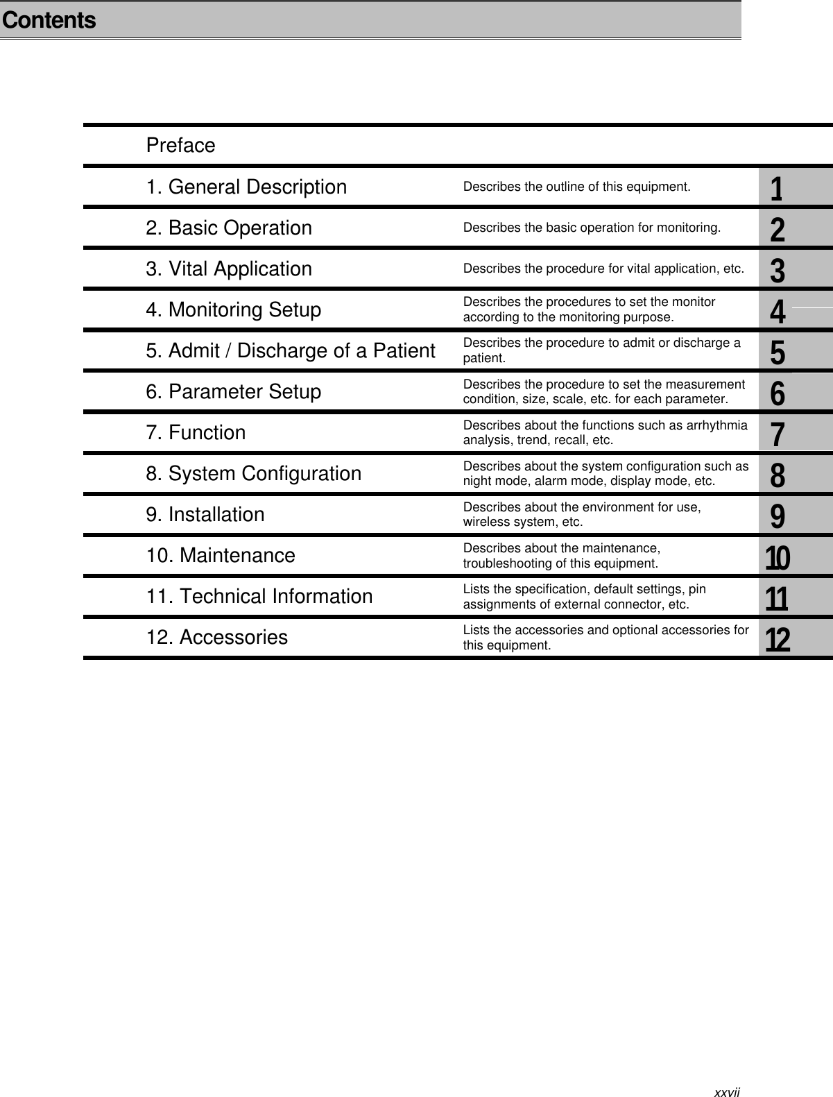
Contents
1.
User manual 1
2.
User manual 2
3.
User manual 3
4.
User manual 4
5.
Manual 5
6.
Manual 6
7.
Manual 7
8.
Manual 9
User manual 1
Navigation menu
Upload a User Manual
Namespaces
Wiki Guide
HTML
PDF
Info
Views
User Manual
Discussion / Help
Navigation
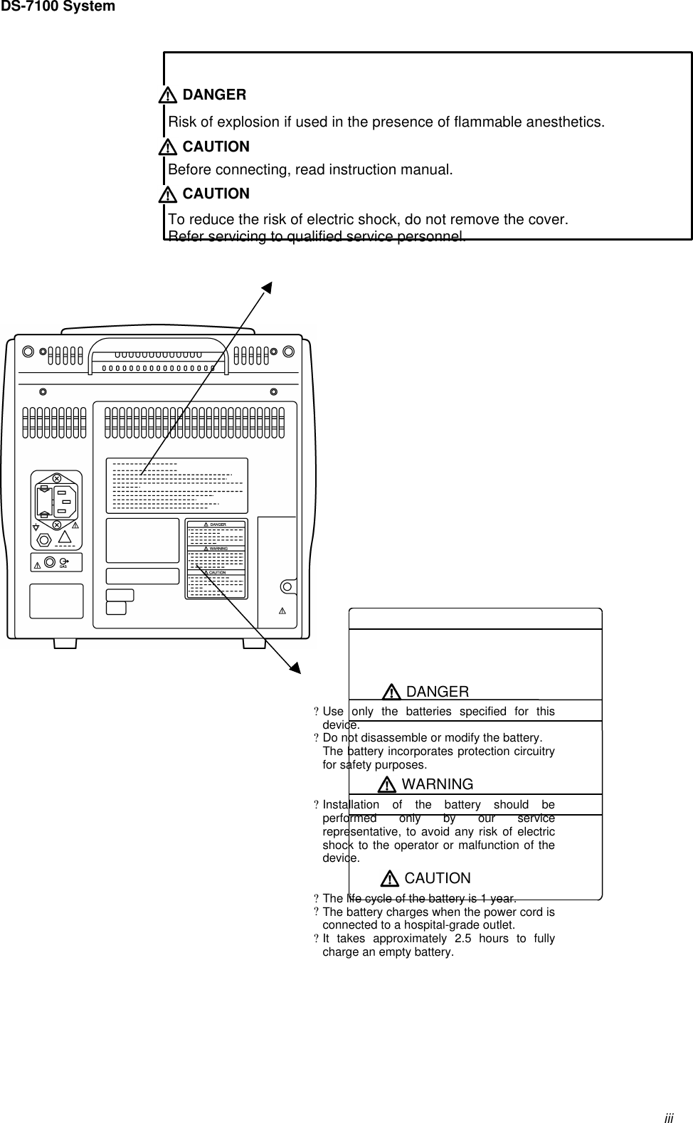
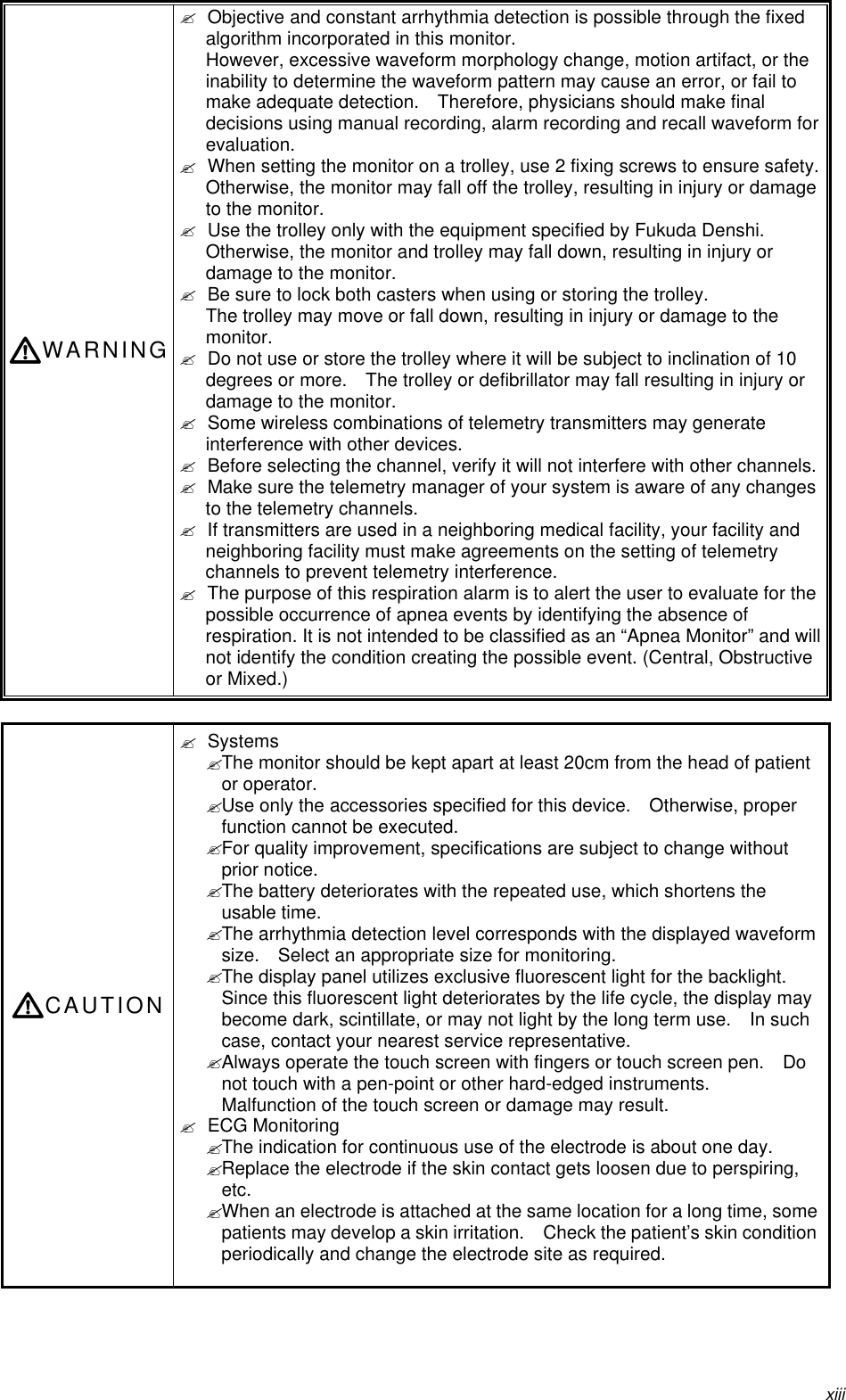
![ixPrecautions about the PacemakerWARNINGMinute ventilation rate-adaptive implantable pacemakers can occasionallyinteract with certain cardiac monitoring and diagnostic equipment, causingthe pacemakers to pace at their maximum programmed rate. The cardiacmonitoring and diagnostic equipment may possibly send wrong information.If such event occurs, please disconnect the cardiac monitoring anddiagnostic equipment, or follow the procedures described in the operationmanual of the pacemaker.(For more details, contact FUKUDA DENSHI personnel, your institution’sprofessionals, or your pacemaker distributors.)Reference“Minute Ventilation Rate-Adaptive Pacemakers”FDA alerts health professionals that minute ventilation rate-adaptive implantable pacemakers can occasionally interact withcertain cardiac monitoring and diagnostic equipment, causingpacemakers to pace at their maximum programmed rate.[October 14, 1998 (Letter: www .fda.gov/cdrh/safety.html) – FDA]Non-Explosion ProofDANGERNever operate the equipment in the presence of flammable anesthetics, highconcentration of oxygen, or inside hyperbaric chamber. Also, do notoperate the equipment in an environment in which there is a risk ofexplosion.Explosion or fire may result.Defibrillation SafetyWARNING? When defibrillating, keep away from the electrodes or medicamentapplied to the patient chest. If this is not possible, remove the electrodesor medicament before defibrillating.If the defibrillator paddles directly contact the electrodes or medicament,electrical shock may result by the discharged energy.? When defibrillating, make sure that the electrodes, sensor cables, or relaycables are firmly connected to the device.Contacting the metal part of the disconnected cable may result inelectrical shock by the discharged energy.? When defibrillating, do not touch the patient and the metal part of thedevice or cables. Electric shock may result by the discharged energy.](https://usermanual.wiki/Fukuda-Denshi-Co/DS7100.User-manual-1/User-Guide-380403-Page-9.png)