Fukuda Denshi Co LX5160 LX-5160 User Manual Manual
Fukuda Denshi Co Ltd LX-5160 Manual
User Manual
EXHIBIT D: User Manual
FCC ID DV8LX5160
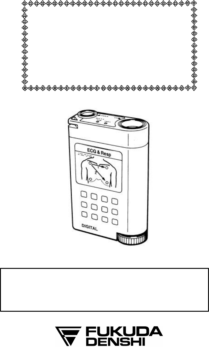
ECG & Respiration Transmitter
LX-5160
Operation Manual
Before using the LX-5160 you must first thoroughly read this
manual.
Remember to keep this operation manual in an easily
accessible place near the unit for future reference.
Only a physician or a person under the guidance of a
physician can use this product.
The information contained in this document is subject
to change without notice due to improvement in the
equipment.
CAUTION
Federal law restricts this device to sale by or on the order of a
physician.
CAUTION
Users are advised to periodically contact the FCC or specified
frequency coordinator and determine if other or your
transmitter frequencies that may cause interference.
CAUTION
The manufacturers, installers and users of Wireless Medical
Telemetry System equipment are cautioned that the operation
of this equipment could result in harmful interference to other
nearby medical devices.
Copyright © 2001 by Fukuda Denshi Co., Ltd.
No part of this document may be copied or transmitted in any form
without the prior written permission of Fukuda Denshi Co., Ltd.
Printed in Japan
Important Information
i
TELEMETRY PRECAUTIONS
For proper management of the telemetry installation, consult your
Fukuda Denshi representative concerning the following:
• Plan the installation of your telemetry system taking into account
your entire medical facility needs and plant requirements.
• Be sure the antenna system installed meets the facility and plant
requirements.
WARNING
This radio frequency device is susceptible to interference from
outside sources. Interference may prevent the monitoring of
patients connected to this devices. If a problems exists,
contact your local service representative.
To assure safe and reliable operation, observe the following
precautions:
• Be sure that no other devices are using the frequency assigned to this
transmitter.
• This device is susceptible to interference from electrosurgical knives
and other computerized equipment. If problems occur contact your
local Fukuda Denshi service representative.
• Any obstruction such as reinforced concrete or large metallic
surfaces between the receiver and the transmitter can affect reception.
If problems occur contact your local Fukuda Denshi service
representative.
• When the low battery alarm is present replace the battery.
CAUTION
The manufacturers, installers and users of WMTS equipment
are cautioned that the operation of this equipment could result
in harmful interference to other nearby medical devices.
ii
Thank you for purchasing this instrument from Fukuda Denshi.
Familiarize yourself with the correct operation of this instrument prior
to operation.
PRECAUTIONS FOR SAFE OPERATION AND HAZARD
PREVENTION
Installation and Storage
• Install or store the instrument where it is free from moisture,
splashed water, excessive dust, salt and direct sunlight.
• Avoid excessive vibration and shock during operation or transport.
• Do not store near chemicals, where gases are generated, or in a
highly sulfuric atmosphere.
Precautions before Operation
• Do not operate this instrument in the presence of flammable gases.
• Ensure the instrument is operating normally and safely.
• When using the instrument in conjunction with another instrument,
follow the appropriate instructions for both instruments.
Caution during Operation
Observe the instrument and patient for any abnormality. If abnormal
operation occurs, remove the instrument from use and have it checked
by the biomedical engineering department or contact your nearest
Fukuda Denshi service representative.
Cautions after Operation
• Turn off the power switch when operation is complete.
• Disconnect cables properly by holding the plug and pulling it out
gently.
• Clean the instrument prior to storing.
Non-explosion-proof
The instrument is not designed for operation in areas in which there
is a risk of explosion.
Be sure to perform a periodical inspection of the instrument and all
accessories.
iii
CLEANING AND DISINFECTION
Electrodes and electrode cables
For disinfection, the electrodes and electrode cables should be
rubbed with a swab or cloth moistened with a formaldehyde
solution, such as Cidex 5%.
Under no circumstances may the electrode cables be immersed in
any cleaning fluid, nor may they be subjected to heat sterilization
with water, steam, or air, or be subjected to ether sterilization.
Transmitter
The transmitter cabinet may be cleaned and disinfected in the
following manner.
Cleaning:
Rub the unit with a cleaning cloth moistened with water to which an
ordinary household cleaning agent can be added if necessary. But
never use ether or benzene.
Disinfection:
Thoroughly spray the cabinet with a 5% Cidex or a similar product.
Any and all modifications must be performed by an authorized
Fukuda Denshi service representative.
iv
CAUTION
Some pacemaker pulses are difficult or not possible to detect.
This is dependent on the amplitude and width of the
pacemaker pulse in addition to the type of pacemaker and
lead type used (unipolar, bipolar, etc.).
CAUTION
QRS detection allows for detection of low amplitude ECG.
But if excessive artifact is present on the ECG waveform, the
noise may be detected as QRS in error.
CAUTION
Make sure each receiving telemetry channel corresponds to
that of the transmitter worn by the patient.
Instruct the patient wearing a telemetry transmitter to remain
within the range of the antenna system.
To avoid interference from other transmitters in the adjacent
area or hospital, make sure the proper channel identification
and group codes are used.
Refer system settings to your Fukuda Denshi service
representative.
CONTENTS
1. GENERAL DESCRIPTION 1
2. CONTROLS AND INDICATORS 2
3. PREPARATION & OPERATION 4
1) Loading Battery 4
2) Turn the power switch to "ON" 5
3) Attaching Electrodes 6
4) Connecting lead wires 9
5) Connect the lead wire set firmly to the transmitter 9
4. SET THE GROUP CODE 10
5. SELECT THE CORRESPONDING
RECEIVER CHANNEL11
6. CLEANING AND DISINFECTION 12
7. MAINTENANCE AND INSPECTION 13
8. SPECIFICATIONS 15
9. ACCESSORIES 16
1
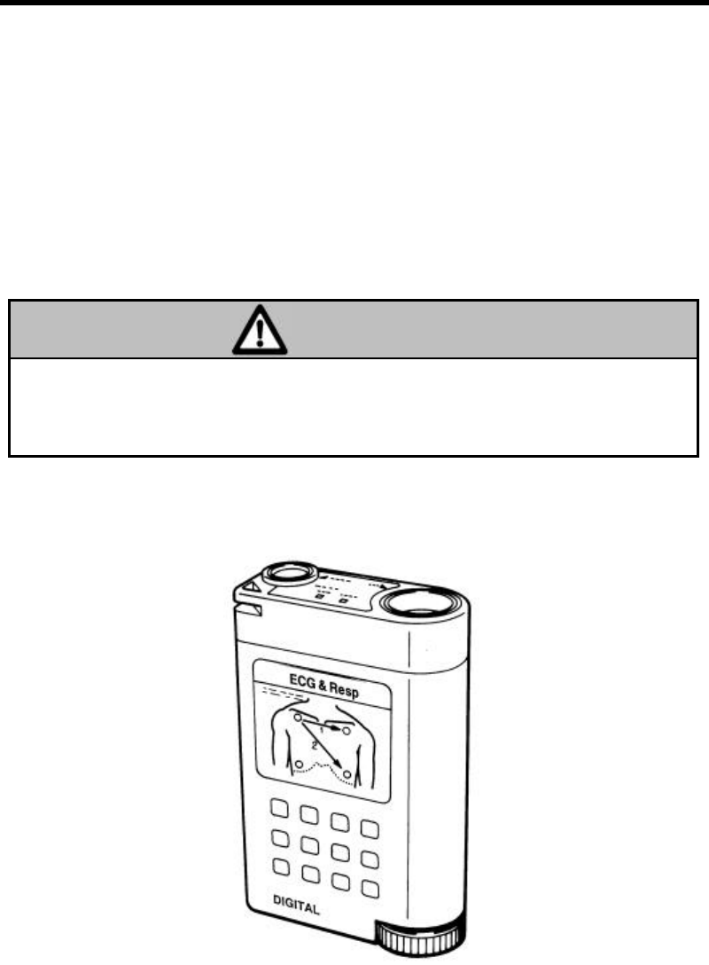
1. GENERAL DESCRIPTION
The LX-5160 is a radio telemetry transmitter designed for monitoring
the ECG and Respiration. The transmitter will operate 5 continuous
days from one "AA" size alkaline battery. On the top panel, battery
and electrodes status displays are provided.
The LX-5160 is transmitting a digitized code that includes the
transmitting channel number and group codes to prevent interference
by other radio apparatus. Read the receiver and display unit
operation manual before using this transmitter.
WARNING
Operation of this equipment requires the prior coordination
with a frequency coordinator designated by the FCC for the
Wireless Medical Telemetry Service.
EXTERNAL APPEARANCE
2
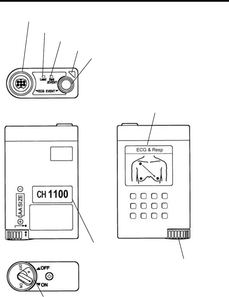
2. CONTROLS AND INDICATORS
ECG/Resp. Input Connector
Poor Electrode Display
Battery/Event Display
Hole for Security Strap
Event Switch
Electrode Position Label
Power Switch
Channel Number Label
Battery Cap
3
ECG/Resp. Input Connector
Connect the accessory patient cable.
Poor Electrode Display
This lamp will light for two minutes when the electrodes are making
poor contact or the patient cables are broken or disconnected.
Battery/Event Display
When the power switch is turned on, the battery check lamp will light
for about 10 seconds. If the battery is low, the lamp will not light
after turning on the power switch. The battery should be replaced
with a new one.
Also, when the Event switch is pressed, this lamp will light.
Hole for Security Strap
Attach the accessory security strap to prevent the transmitter from
dropping. Adjust the length of the strap to the appropriate length for
the patient.
Event Switch
When this switch is pressed, this function will be activated at the
receiver. This can be designated on or off at the receiver.
Channel Number label
The transmitter channel number is printed on this label. Select the
receiver channel to correspond to this channel number.
Battery Cap
This is the battery compartment cap. To close the battery
compartment, align the mark on the cap and arrow mark on the lower
part of the transmitter, then push and turn the cap clockwise to align
the dot-marks with each other.
Electrode Position Label
Typical electrode positions are shown on this label.
Power Switch
This is the power switch. When the switch is turned to the ON
position, the "Batt." lamp will be lit for about 10 seconds.
If the battery is weak or has no power, the "Batt." lamp will not light
even when the switch is turned to the ON position.
4
3. PREPARATION & OPERATION
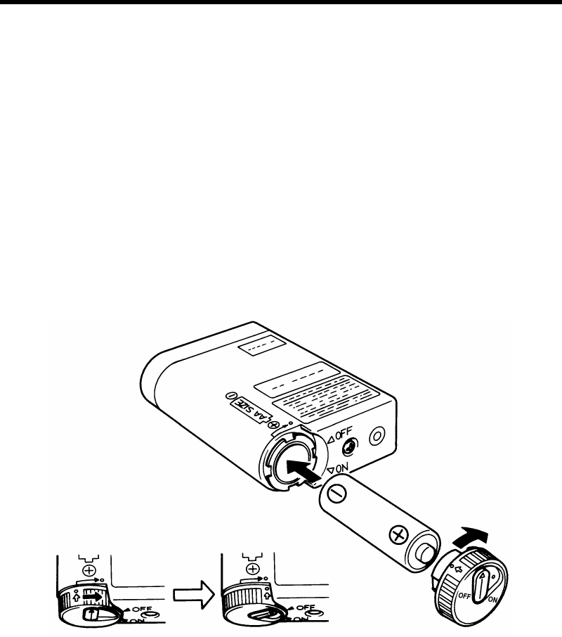
Loading a battery
The LX-5160 uses one "AA" size alkaline cell (LR-6) for its power
source.
When installing a battery taking note of the polarity. To close the
battery compartment, align the mark (yellow) on the cap and the mark
(yellow) on the lower part of the transmitter, then gently push in and
turn the cap clockwise to the mark (white) on the transmitter to align
the dot-marks (white & yellow) with each other.
If the transmitter is not in use for a long period of time, remove the
battery and store in an appropriate place.
5
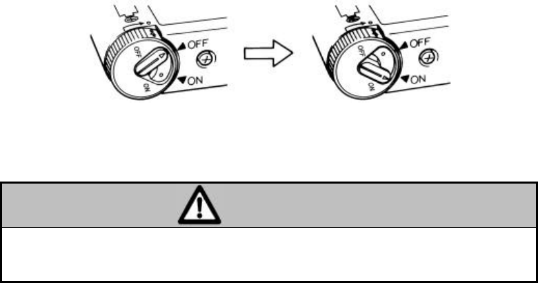
Turn the power switch to "ON"
Turn the power switch, which is located at the bottom of the
transmitter, on the battery cap, to the "ON" position.
The battery life will be approximately 5 days of continuous operation.
CAUTION
Do not use in high humidity or in areas of high oxygen
concentration.
6
Attaching the electrodes
Wipe the skin at the electrode site with alcohol. Then detach the
electrode from the electrode mount and attach it to the electrode site.
Color coding of the electrode positions are shown below.
Adhesive tape should be used to tape the electrode wire to the skin to
prevent the lead wire from moving on the electrode.
With the LX-5160 impedance measurements are used for respiration
monitoring. There is a possibility that a large amplitude ECG signal
will not always provide a large respiration signal. In general, lead
CC5, as illustrated below, will provide the best respiration waveform.
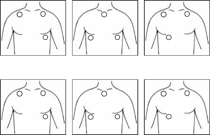
EXAMPLE OF ELECTRODE POSITIONS
For single lead ECG and respiration monitoring, use the CM-85B for
AHA color code or CM-86B for IEC color code patient cable (three
electrodes). AHA color code is applied in U.S.A. and IEC color code
is applied in Europe.
AHA color code electrode position Respiration sensing : White and Red
LEAD LEAD CC5 LEAD MCL1
IEC color code electrode position Respiration sensing : Red and Yellow
LEAD LEAD CC5 LEAD MCL1
White
White
White
Red
Red
Red
Black
Black Black
Red
Red
Red
Black
Black Black
Yellow Yellow
Yellow
7
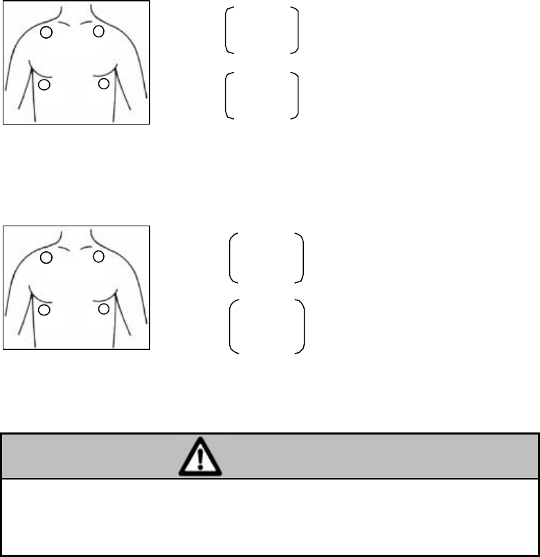
For two lead ECG and respiration monitoring, use the CM-85C for
AHA color code or CM-86C for IEC color code patient cable (four
electrodes).
AHA color code electrode position
LEAD and LEAD
IEC color code electrode position
LEAD and LEAD
CAUTION
The CM-85 and CM-86 series patient cable are designed for
ECG and Respiration monitoring. Other patient cables will
not measure the respiration signals.
Red
White
Black
Green
Red
Green
Black
Yellow
+
: Black
CH 1 LEAD
− : White
+ : Red
CH 2 LEAD
− : White
Reference : Green
Respiration sensing : White and Red
+
: Yellow
CH 1 LEAD
− : Red
+ : Green
CH 2 LEAD
− : Red
Reference : Black
Respiration sensing : Red and Green
8
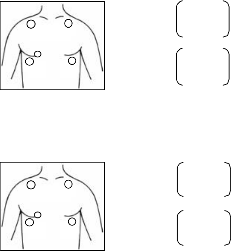
For dual channel ECG and respiration monitoring, use the CM-85D
for AHA color code or CM-86D for IEC color code patient cable (five
electrodes).
AHA color code electrode position
LEAD and LEAD MCL 1
IEC color code electrode position
LEAD and LEAD MCL 1
Red
White Black
Green
Brown
+
: Red
CH 1 LEAD
− : White
+ : Brown
CH 2 LEAD
− : Black
Reference : Green
Respiration sensing : White and Red
Red
Green
Black
Yellow
White
+
: Green
CH 1 LEAD
− :
+ : White
CH 2 LEAD MCL
− : Yellow
Reference : Black
Respiration sensing : Red and Green
9
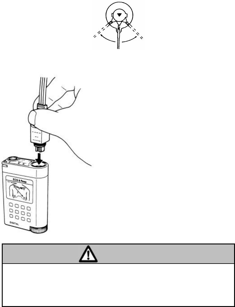
Connect the lead wires to the electrode.
Connect the tip of lead wire to the center of the electrode and gently
swing it right and left as shown below.
Connect the lead wire set firmly to the transmitter.
CAUTION
Confirm the direction of the keyed plug to match the
transmitter's guide key on the connector. Improper
connection will cause damage to the transmitter, patient cable,
and will not provide proper monitoring.
Connect the patient cable firmly to
the ECG/Resp. input connector of
the transmitter.
When disconnecting the patient
cable, do not disconnect the lead
wire set by pulling on the wires.

10
4. SET THE GROUP CODE
The LX-5160 transmits a digitized code which includes the
transmitting channel number and group code to prevent interference
from other radio apparatus or a neighboring hospital's transmitter.
There are 64 group codes. Zero ("0") is set for factory adjustment.
The receiver is required to set the group code to match the
transmitter's group code (The receiver group code's factory adjustment
is "0").
The receiver is continuously checking the incoming channel number
and group code versus the number and code programmed to the
receiver. If the transmitter's group code is required to be changed,
please contact Fukuda Denshi.
NOTE: The system function to prevent interference will not
work if the receiver does not incorporate this function.
11
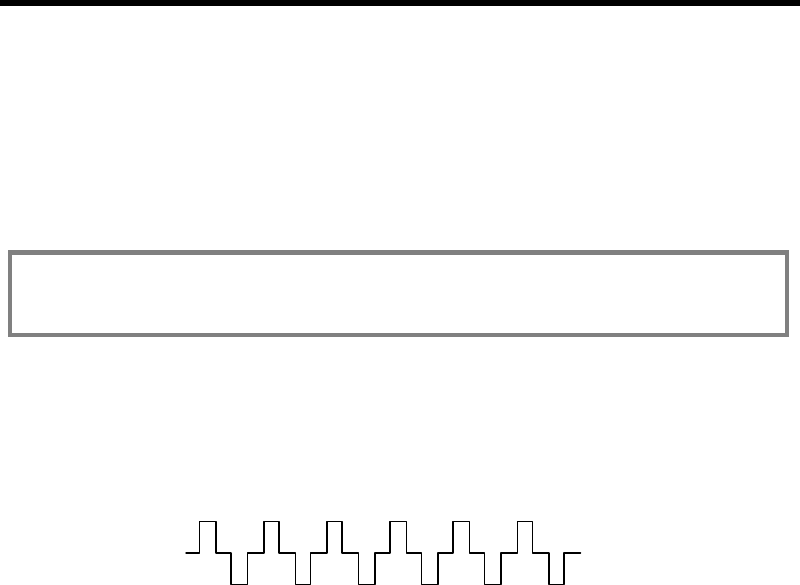
5. SELECT THE CORRESPONDING
RECEIVER CHANNEL
Select the receiver channel at the patient monitor to correspond to the
telemetry transmitter. The channel number will be displayed on the
screen display. If the receiver channel and transmitter channel do not
match, the monitor will display a caution and the unique waveform
shown below. This function will prevent telemetry channel
interference from other transmitters or external sources.
NOTE: This function will only be active if this has been
incorporated into the receiver.
Example of the DS-5800N telemetry patient's display when
interference is present.
This unique waveform will also be displayed when a group or channel
number mismatch occurs.

12
6. CLEANING AND DISINFECTION
Clean the transmitter and patient cable with gauze or sanitary cotton
dampened with alcohol or inert soap. Be sure not to get cleaning
liquid into the patient lead connector and battery compartment.
Do not use cleaner containing organic solution, thinners, toluene,
benzene. Do not autoclave or heat the unit and patient cable above
60°C.
When the room is disinfected by spraying, take proper measures so the
chemical solution does not get on the connector or enter into the inside
of the enclosure.
13
7. MAINTENANCE AND INSPECTION
Items in this section include routine daily and periodic checks of the
equipment to ensure it is operating properly.
It is recommended that to maintain the safety and reliability of
functions and performance of the unit, the daily and periodical checks
given in this section be followed.
CAUTION
Do not open the unit or attempt service. Refer service to
Fukuda Denshi.
Do not allow excessive moisture or cleaning agents into the
connectors or the inside of the housing.
Daily Check
Perform daily checks in accordance with the recommended daily
check list.
Periodical Check
Periodical checks of the equipment for safety and performance of
medical equipment is normally required by every institution at least
once or twice per year. Contact Fukuda Denshi for recommended
periodic maintenance.

14
Daily Check List
No.
Date Checker Installation Place
Unit LX-5160 S/No. Purchase Date
Items Details of the Check Criteria Judgement
Appearance
Visually check for any
damage, cracks, chink, chips
and peeled nameplate on the
outer enclosure.
No abnormality. OK
NG
Battery
Compart-
ment
Visually check the connecting
spring on the inside of the
device and battery cap.
No spring transformed,
deformed or rusted. OK
NG
Power Turn ON/OFF power to verify
proper switch
operation.
With battery in, the Batt.
lamp will be illuminated
for about 10 seconds.
OK
NG
ECG
Connector
Visually check for plug
connector of main unit and
patient cable.
No scratch and chips.
No dust attached. OK
NG
Patient
Cable Visually check for wire
coating of patient cable. No cracks, kinks, or
damage. OK
NG
Wireless
Channel
Visually verify the transmit
channel, and group No.
Follow instructions of the
wireless channel manager for
the receiver.
Must correspond with
wireless channel check
list.
OK
NG
Function Turn on the power and make
sure operation is normal. Waveform is received
without any problem. OK
NG
Periodic
Check Check the dates of previously
performed periodic checks. Should be within one
month. OK
NG

15
8. SPECIFICATIONS
Parameters : 1 or 2 channel ECG and respiration
ECG input impedance : More than 50 Meg-ohms
ECG max. input range : ±5 mV
ECG freq. response : 40 Hz (refer to the receiver filter also)
ECG time constant : 0.8 seconds (1.5 seconds for option)
Resp. measurement : Impedance pneumography
Resp. max. input range : ±5 ohms
Resp. meas. electrodes : RA & LL, ECG channel 1
Resp. freq. response : 0.3 to 3 Hz (refer to the receiver filter
also)
Defibrillator protection : By protection circuit in the patient cable
Status information : Electrode fail, Low battery (below 1 volt),
Event switch, Pacemaker detection,
Channel ID, 64 kinds of Group code
Transmission freq. : 608∼614 MHz
RF output power : 1.0 mW ±2 dB
Channel spacing : 12.5 kHz
Occupied band width : 8.5 kHz
Modulation mode : Digital, Frequency shift keying
Power source : One 1.5 V AA size alkaline battery
Battery polarity protection : Mechanical reverse polarity protection
Battery life : 5 days min.
Water immersion degree : Per IP-66
Weight : Approx. 110 g (including battery)
Dimensions : 54(W) × 86(H) × 22(D) mm
Operating temperature : 10 to 40 °C
Operating humidity : 30 to 85 % RH (no dew condition)
Storage temperature : -10 to 60 °C
Storage humidity : 10 to 95 % RH
CAUTION: Specifications are subject to change
without prior notice.
16
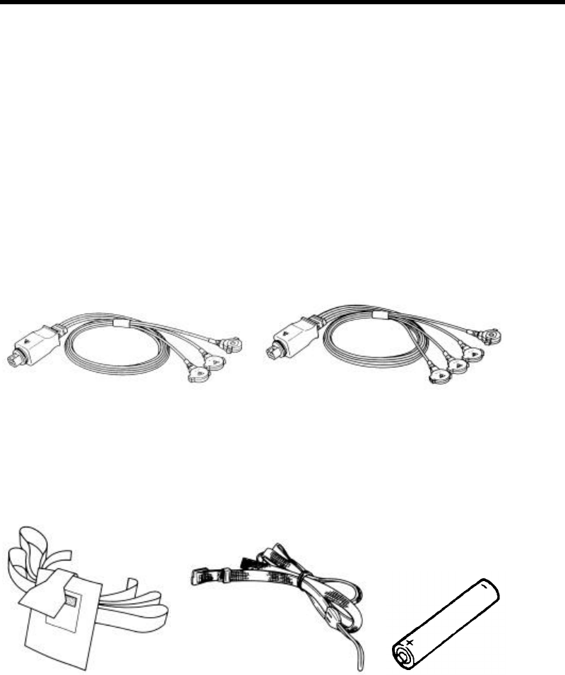
9. ACCESSORIES
Standard Accessories
Patient cable : One CM-85B or CM-86B, three electrodes
type or CM-85C or CM-86C, four electrodes
type. The type of the cable depends on the
destination.
Pouch : Two AB-95, disposable pouch
Security Strap : One OB-25 belt kit
Battery : One LR-6, 1.5 V alkaline AA battery
Instruction manual : One
Patient cable Patient cable
CM-85B(AHA color code) CM-85C(AHA color code)
CM-86B(IEC color code) CM-86C(IEC color code)
Pouch AB-95 Security Strap Battery
OA-25 LR-6
17
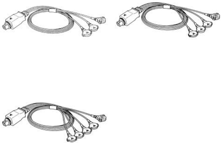
Optional Accessories
CM-85B or CM-86B, Patient cable for single ECG lead and
respiration.
CM-85C or CM-86C, Patient cable for two ECG lead , and
respiration.
CM-85D or CM-86D, Patient cable for dual ECG for any two
channel differential ECG and Respiration, five electrode type.
Patient cable Patient cable
CM-85B(AHA color code) CM-85C(AHA color code)
CM-86B(IEC color code) CM-86C(IEC color code)
Patient cable
CM-85D(AHA color code)
CM-86D(IEC color code)

Head office : 39-4, Hongo 3-chome, Bunkyo-ku, Tokyo, Japan
Phone : -81-3-3815-2121
Telex : 23498 FUKUMED J
Fax : -81-3-5684-3791
4L2870 200102
E